Olympus Medical Systems RU2020 Endoscope Reprocessor User Manual GT9883 0004 fm10
Olympus Medical Systems Corp. Endoscope Reprocessor GT9883 0004 fm10
Contents
Installation Manual 2
4.5 Connection of the drain hose
61
OER-Elite INSTALLATION MANUAL
Ch.4
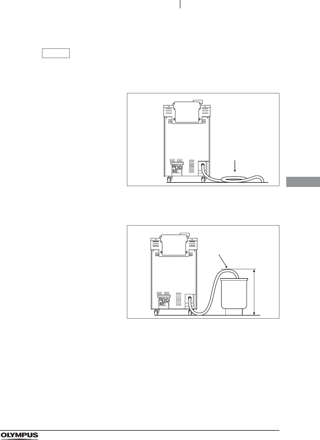
Connection of drain hose (Supplementary information)
NOTE
• Cut the drain hose to an optimum length by considering the length when it is pulled
out for maintenance. When pushing the equipment against the wall, make sure any
excess section of the hose is laid horizontally on the floor.
Figure 4.8
• The recommended drain pipe diameter is 100 mm (3.9 in). As this can vary for
different facilities, check with your facilities’ maintenance personnel or a plumber.
Figure 4.9
Example 1
No buckling.
Example 2
No buckling.
Hd 60 cm
(23 in)
62
4.5 Connection of the drain hose
OER-Elite INSTALLATION MANUAL
Ch.4
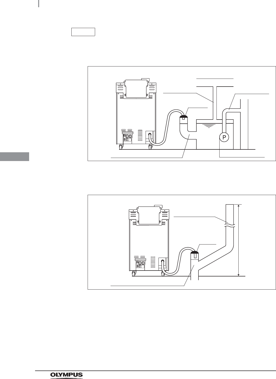
NOTE
• The drain hose connection examples below are intended to show different draining
concepts. When connecting the drain hose, be sure to check with your facility’s
maintenance personnel or a plumber.
Figure 4.10
• If you plan to exhaust air near the ceiling, the ceiling height should be 2 m or more
or the air discharge pipe should be connected to the building’s air vent.
Figure 4.11
(1) Reserve tank + Submersible pump
100 mm (3.9 in) pipe is desirable.
40 to 50 mm
pipe is enough.
Submersible pump
Air vent
Air discharger
Sealing
(2) Discharging air when discharging air from the floor drain opening is
insufficient
100 mm (3.9 in) pipe is desirable.
2m
100 mm (3.9 in)
pipe is desirable.
Sealing
4.5 Connection of the drain hose
63
OER-Elite INSTALLATION MANUAL
Ch.4
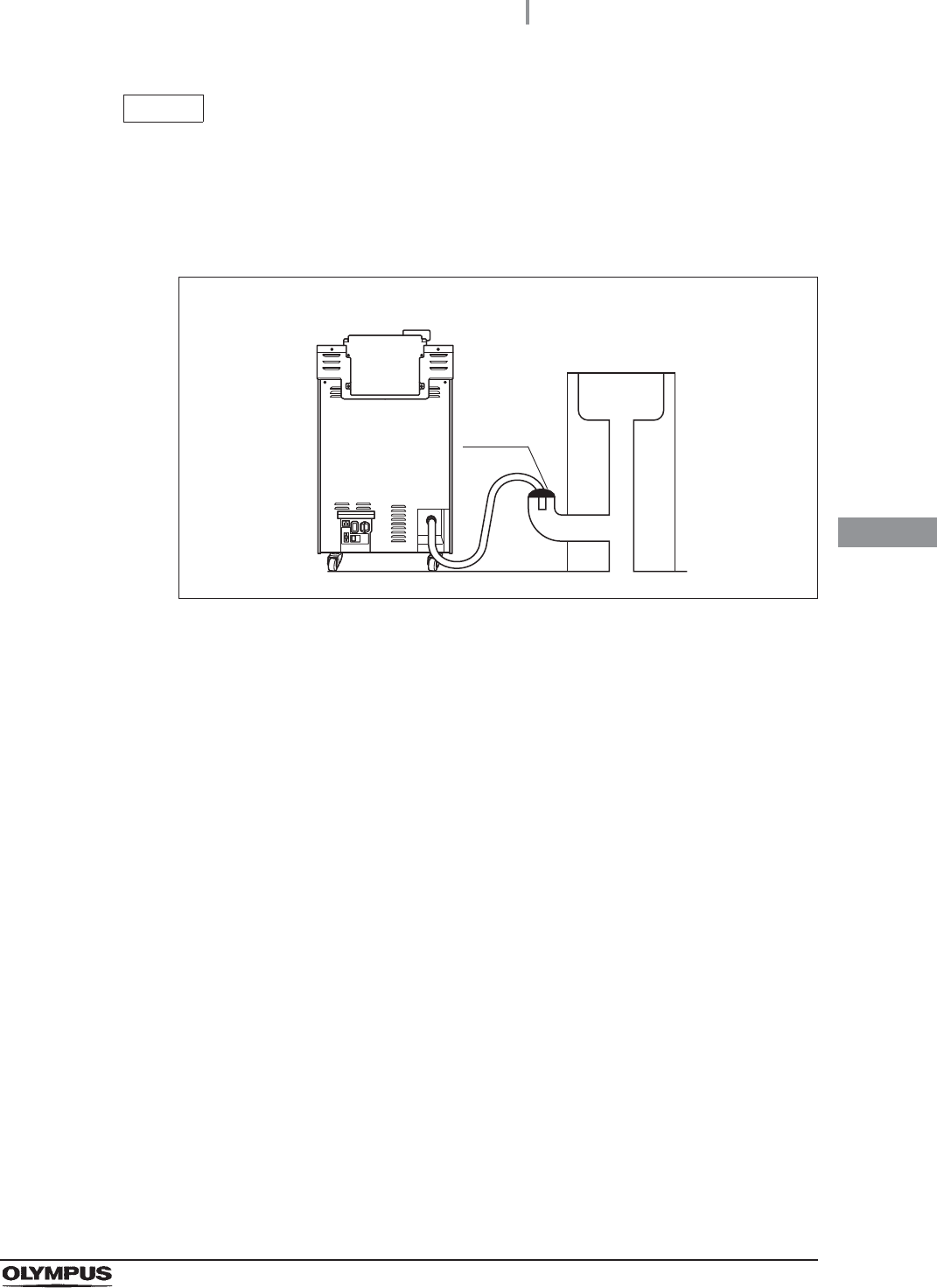
NOTE
• If you plan to use the drainage line of a sink, check the following:
The pipe diameter should be 100 mm (3.9 in) or more.
A backflow prevention structure should be provided.
An air discharge should be provided.
Figure 4.12
(3) Using a sink
Sealing
Sink
64
4.6 Connection of the power supply
OER-Elite INSTALLATION MANUAL
Ch.4
WARNING
• Always connect the power cord plug into a grounded, hospital-grade, wall mains
power outlet. Never use a multi-outlet tap. Always connect directly to a wall mains
power outlet. The equipment must be grounded via the power cord plug.
Connecting the equipment to anything but a grounded wall mains power outlet may
cause an electric shock or a fire.
• Do not allow the power cord plug to get wet. A wet plug can cause an electric
shock.
• To prevent an electric shock, do not touch the power cord plug with wet hands or
touch the power source directly.
• After connecting the power cord, do not to push the rear of the equipment against a
wall. The power cord could break and cause an electric shock or a fire.
• Make sure that the grounded wall mains power outlet meets the power
specifications required by this unit. Insufficient capacity may result in a fire or
activation of the facility’s circuit breakers, which will turn off the power to all other
equipment connected to the same power line.
• Always use the power cord provided with this equipment. Otherwise, equipment
failure or power cord burnout could result. Also, remember that the provided power
cord is for exclusive use with this equipment and should not be used with other
equipment.
4.6 Connection of the power supply
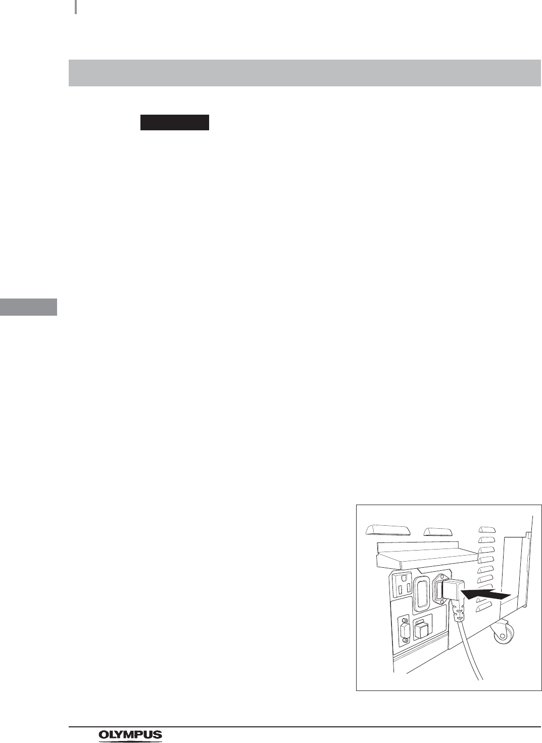
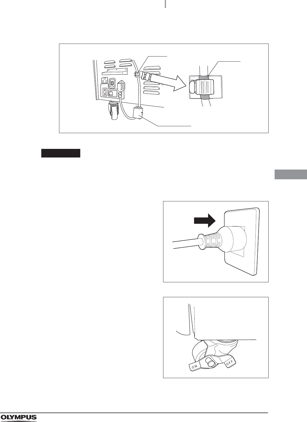
1Check that the power switch of the equipment is set to OFF (When you press the
power switch, you will feel a click when set to ON and no click when set to OFF).
2Insert the power cord all the way into the
connector on the rear (bottom left).
Figure 4.13
4.6 Connection of the power supply
65
OER-Elite INSTALLATION MANUAL
Ch.4
3Clip the marking on the power cord with the clamp.
Figure 4.14
CAUTION
Properly attach the power cord to the clamp so that the ferrite core of the power
cord does not touch the floor. Otherwise, the ferrite core may be caught between
the equipment and floor and break when you move the equipment.
4Connect the power cord plug into a
hospital-grade, wall mains power outlet that
meets the input power conditions indicated on
the rating plate.
Figure 4.15
5Press the ON side of each of the two casters on
the bottom front to lock them.
Figure 4.16
Marking
Clamp
Ferrite core
66
4.7 Confirmation of the power supply
OER-Elite INSTALLATION MANUAL
Ch.4
If the touch screen displays nothing or the power indicator does
not light up:
If the touch screen displays nothing or the power indicator does not light up, turn the power OFF,
wait at least 5 seconds and turn it ON again. If the problem persists, turn the power OFF and
contact Olympus.
4.7 Confirmation of the power supply
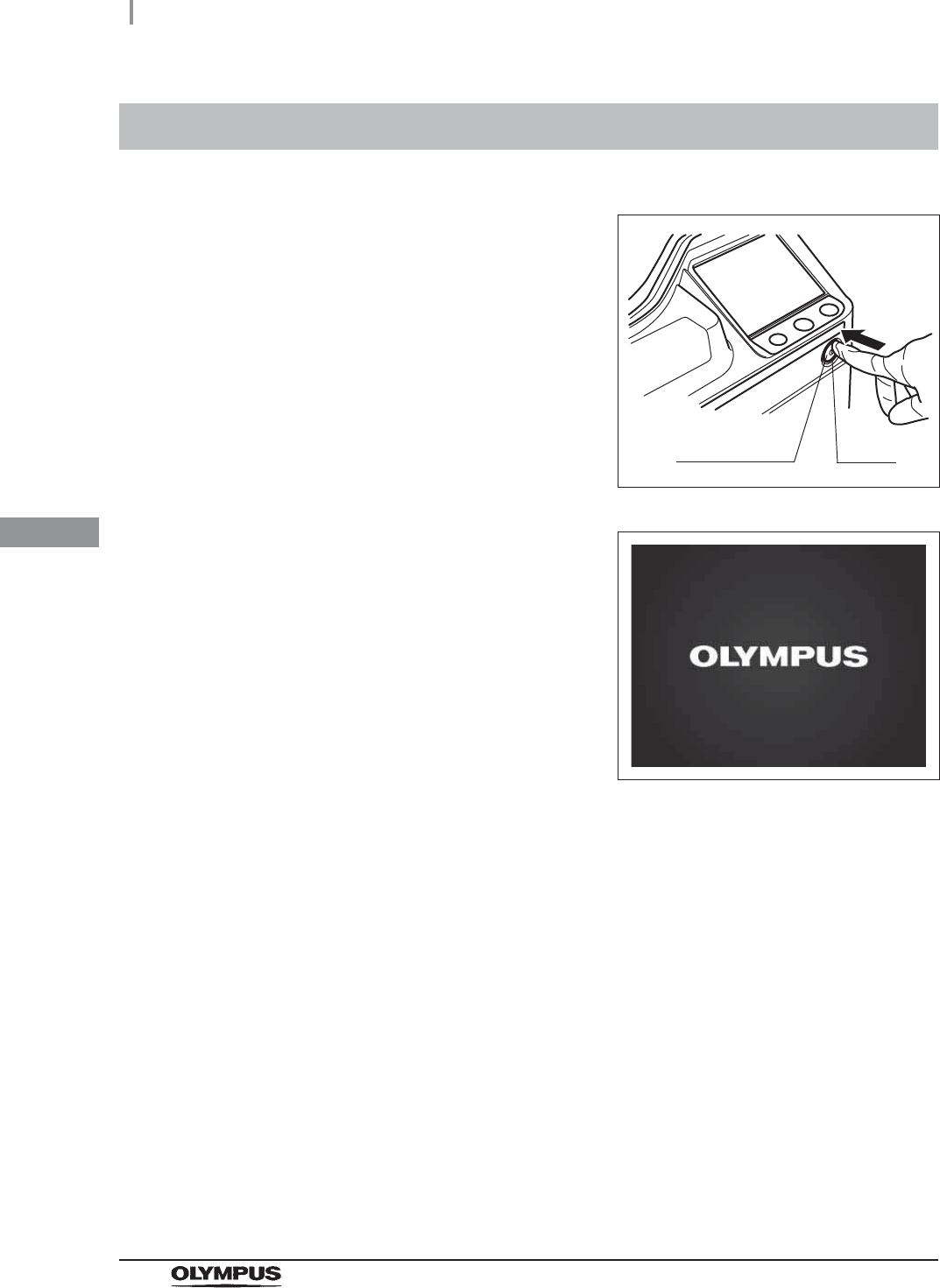
1Press the power switch ON.
Figure 4.17
2Make sure that the power indicator lights up
and the touch screen displays the Start screen
as shown in following figure.
Figure 4.18
Power switch Lamp
4.7 Confirmation of the power supply
67
OER-Elite INSTALLATION MANUAL
Ch.4
If the touch screen has no display and the power indicator does
not light up:
If the touch screen has no display and the power indicator does not light up, inspect the
equipment by following the procedure below. If the problem persists, turn the power OFF and
contact Olympus.
WARNING
• Before removing the fuse holder, be sure to turn the power switch OFF and unplug
the power cord from the equipment and power outlet. Otherwise, a fire or an
electric shock may result.
• To prevent an electric shock, do not replace the fuses with wet hands.
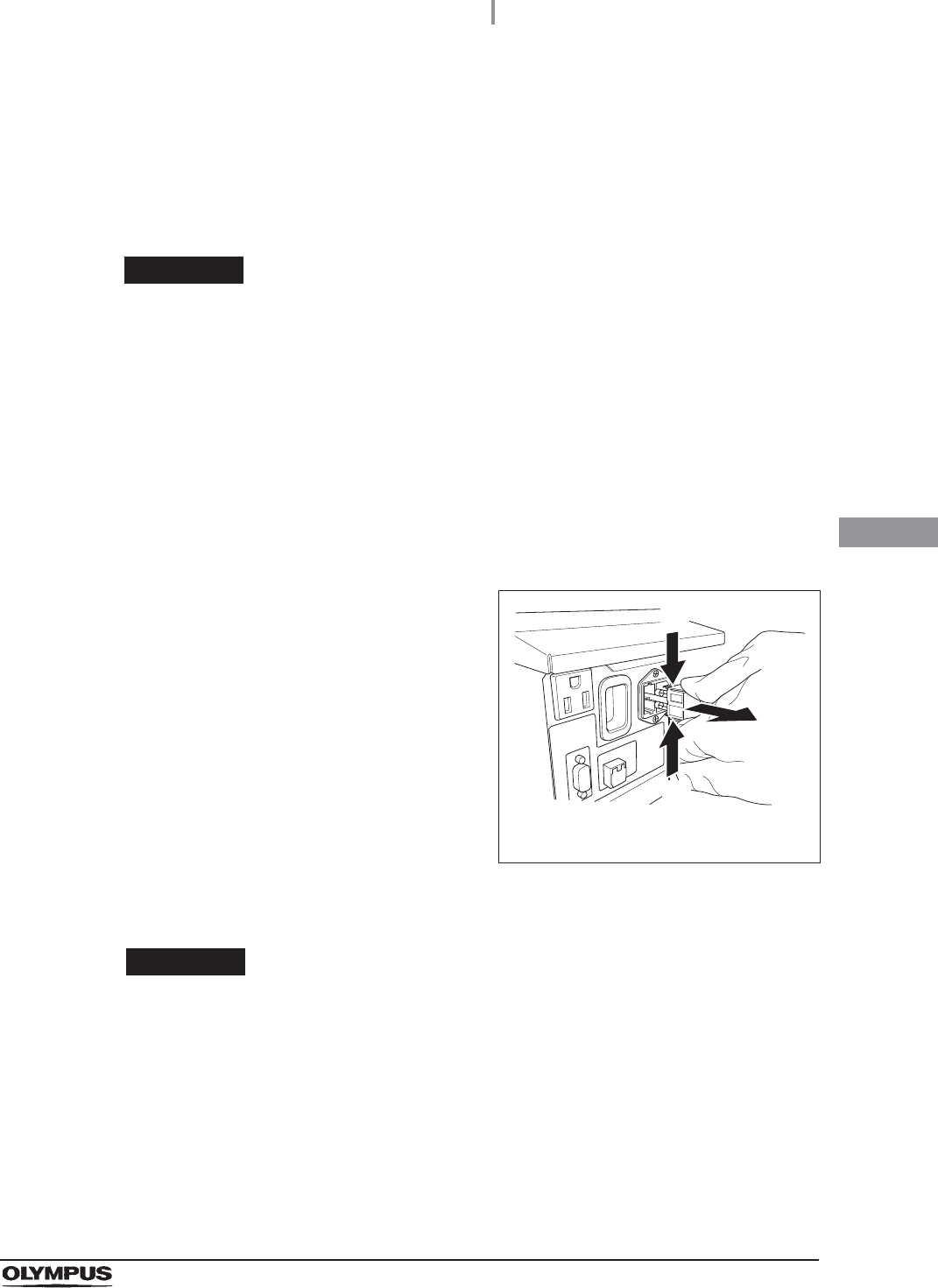
1Ensure that the power cord is connected securely to the connector on the equipment
and to a hospital-grade, wall mains power outlet.
2Turn power OFF and unplug the power cord from the power outlet.
3Unplug the power cord from the power cord receptacle on the equipment.
4Push the tabs on the fuse holder in the
directions shown and take out the fuses.
Figure 4.19
5Visually confirm that neither of the two fuses is blown.
WARNING
Always use the fuses specified below. Otherwise, malfunction or failure of the
equipment may cause a fire or an electric shock.
Spare fuses: DB181500
The numbers in the figure indicate the
fuse box removal sequence.
(1)
(2)
(1)
68
4.7 Confirmation of the power supply
OER-Elite INSTALLATION MANUAL
Ch.4
CAUTION
If the power indicator does not light up even if neither fuse is blown or after both
fuses are replaced, contact Olympus.
Figure 4.20
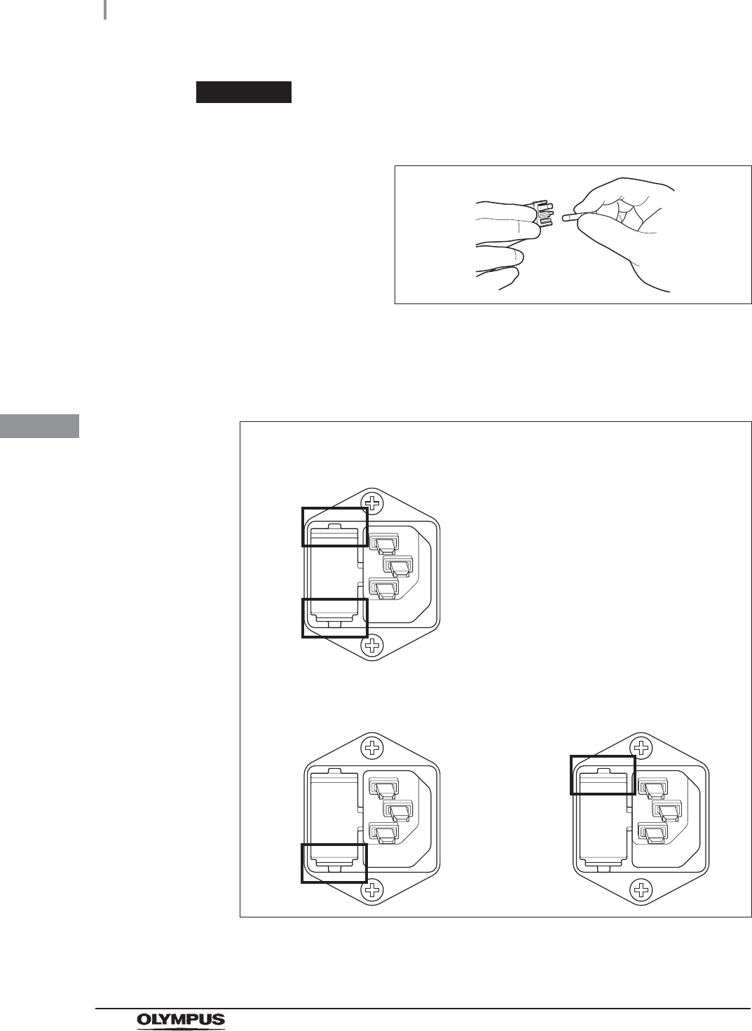
6Insert the fuse holder into the equipment until it clicks. Confirm that the fuse holder is
properly installed, referring to Figure 4.21.
Figure 4.21
7Connect the power cord, turn the power ON and make sure the power indicator lights
up.
The fuse holder is properly installed
(Both the top and bottom projections touch the surface of the fuse holder
cavity)
The fuse holder is not properly installed
(Both the top and bottom projections do not touch the surface of the fuse holder
cavity)

4.8 Inspection of the RFID function
69
OER-Elite INSTALLATION MANUAL
Ch.4
WARNING
If the power indicator does not illuminate even after the fuses have been replaced,
be sure to unplug the power cord from the power outlet. Otherwise, an electric
shock may result.
This equipment can store the scope ID, user ID, and physician ID entered by RFID in the log of each
process.
WARNING
Be aware that the radio waves emitted from the RFID reader of the equipment may
cause medical devices such as pacemakers to malfunction. If any interference with
the equipment is observed, immediately move away from the RFID reader or set
the power switch to OFF. Call your doctor if you do not begin to feel better.
CAUTION
Electromagnetic interference from other devices may shorten the communication
distance of the designated ID tag and cause signals to become unreadable. Try to
take mitigation measures such as keeping the affecting device far enough away
from this equipment to eliminate this type of interference.
NOTE
• In the step 4 below, if the endoscope is not any of 180 series, 190 series, or
endoscopes with the external ID tag, use the Scope ID master card (GT970700).
• If entering a user ID is not done by RFID in the reprocessing process or each
function, skip the steps 6 and 7 below.
• If entering a physician ID is not done by RFID in the reprocessing process or each
function, skip the steps 8 and 9 below.
Perform the inspection procedure described below. Also, use the following procedure to check if the
scope ID tag on each endoscope matches the actual scope information, if the user ID matches the
actual user information, and if the physician ID matches the actual physician information.
4.8 Inspection of the RFID function
70
4.8 Inspection of the RFID function
OER-Elite INSTALLATION MANUAL
Ch.4
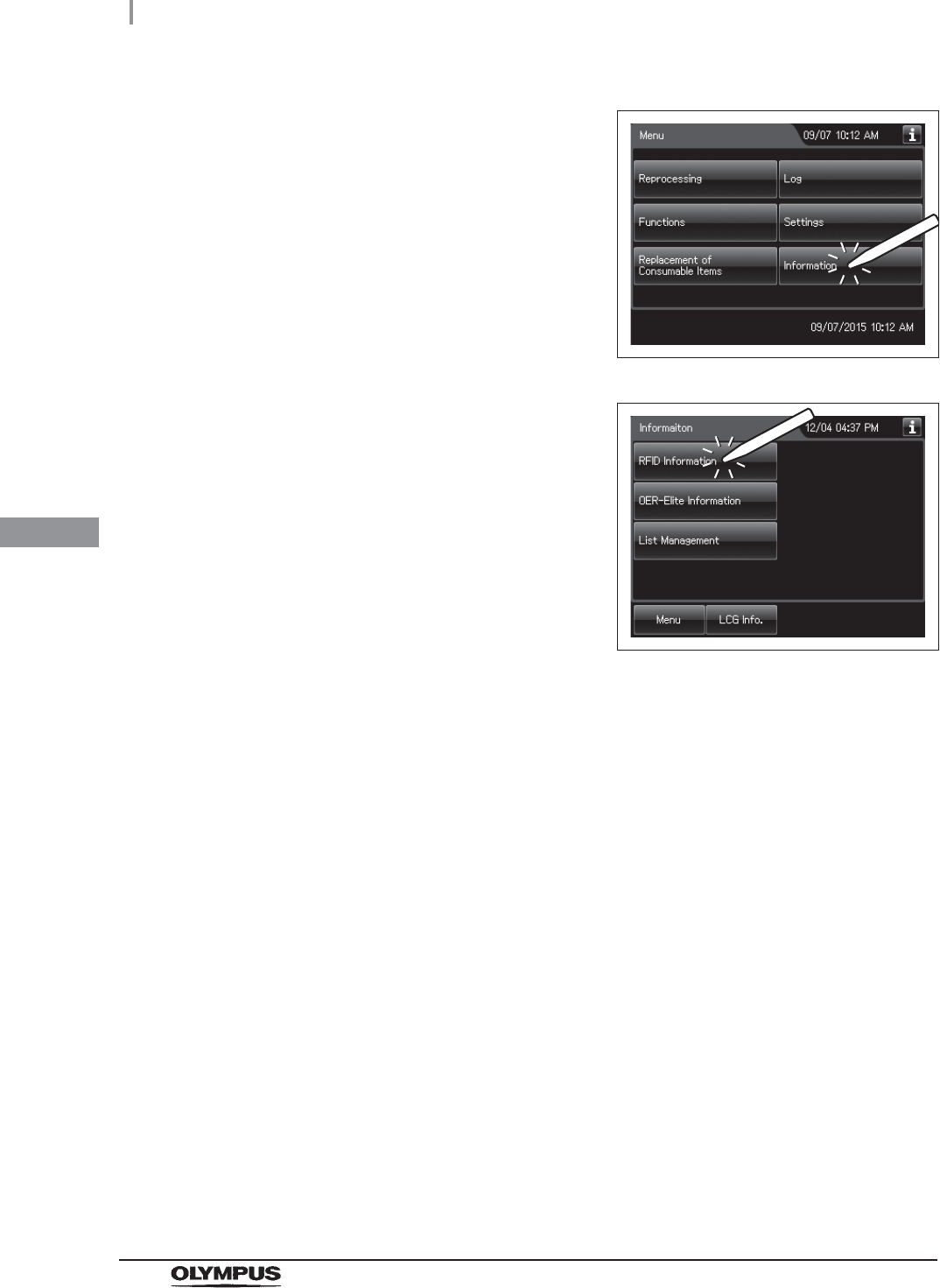
1Press the “Information” button on the menu
screen.
Figure 4.22
2Press the “RFID Information” button.
Figure 4.23
3Check that the scope ID tag is attached to each scope as defined in the instruction
manual for the scope ID tag.
4.8 Inspection of the RFID function
71
OER-Elite INSTALLATION MANUAL
Ch.4
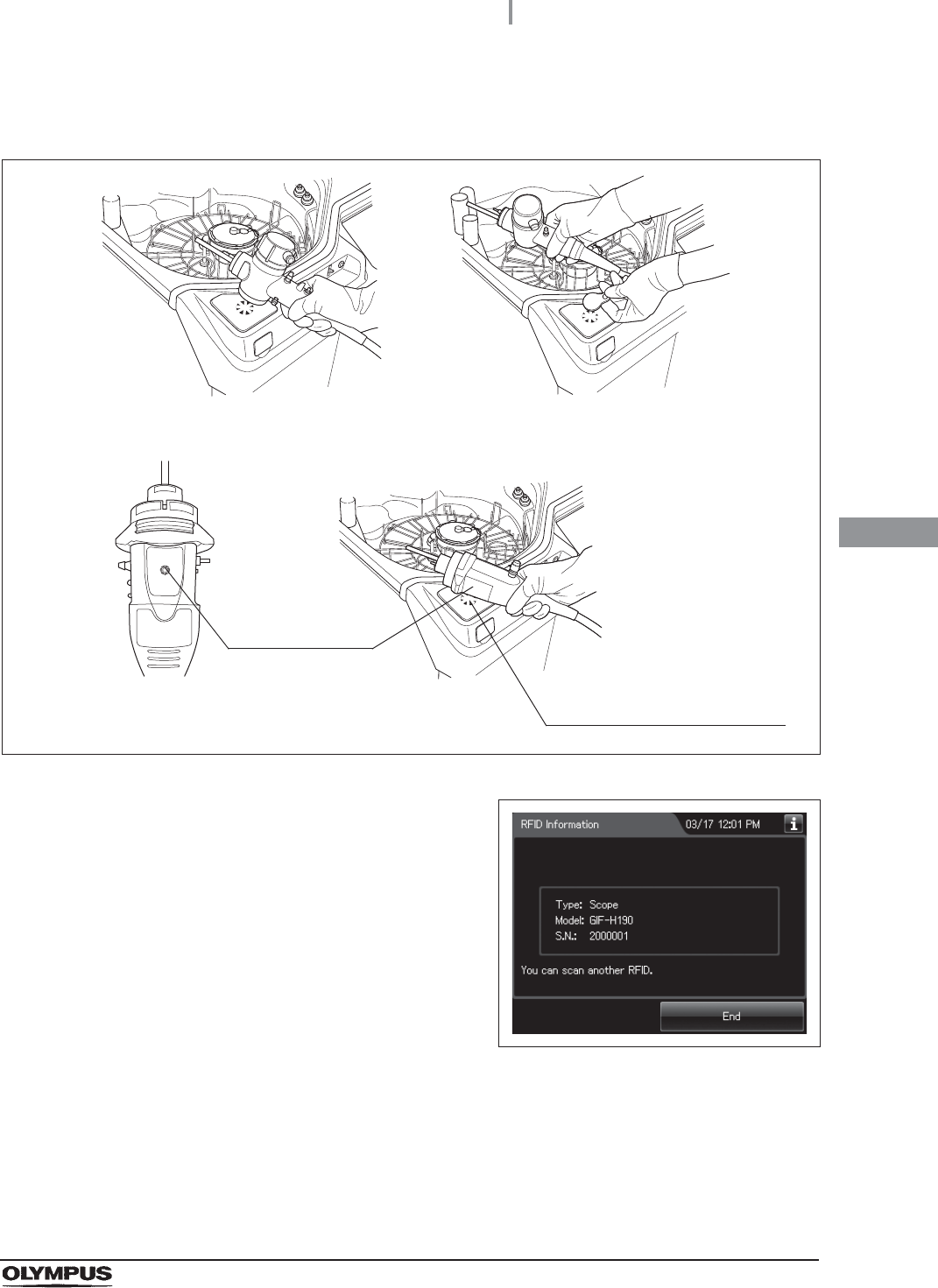
4Hold the internal ID-type endoscope connector or the external ID tag to the ID reader
section of the equipment and scan the tag with the reader until a short beep sounds.
Figure 4.24
5The information on the scope ID is displayed on
the touch screen.
Figure 4.25
For internal ID-type endoscope
(For example 180 series endoscope)
For external ID tag
For internal ID-type endoscope
(190 series endoscope1)
Approach the scope ID mark
on the endoscope connector of
190 series1 to the RFID
reader of the equipment.
Scope ID mark
1 190 series endoscopes may not be available in some areas.
72
4.8 Inspection of the RFID function
OER-Elite INSTALLATION MANUAL
Ch.4
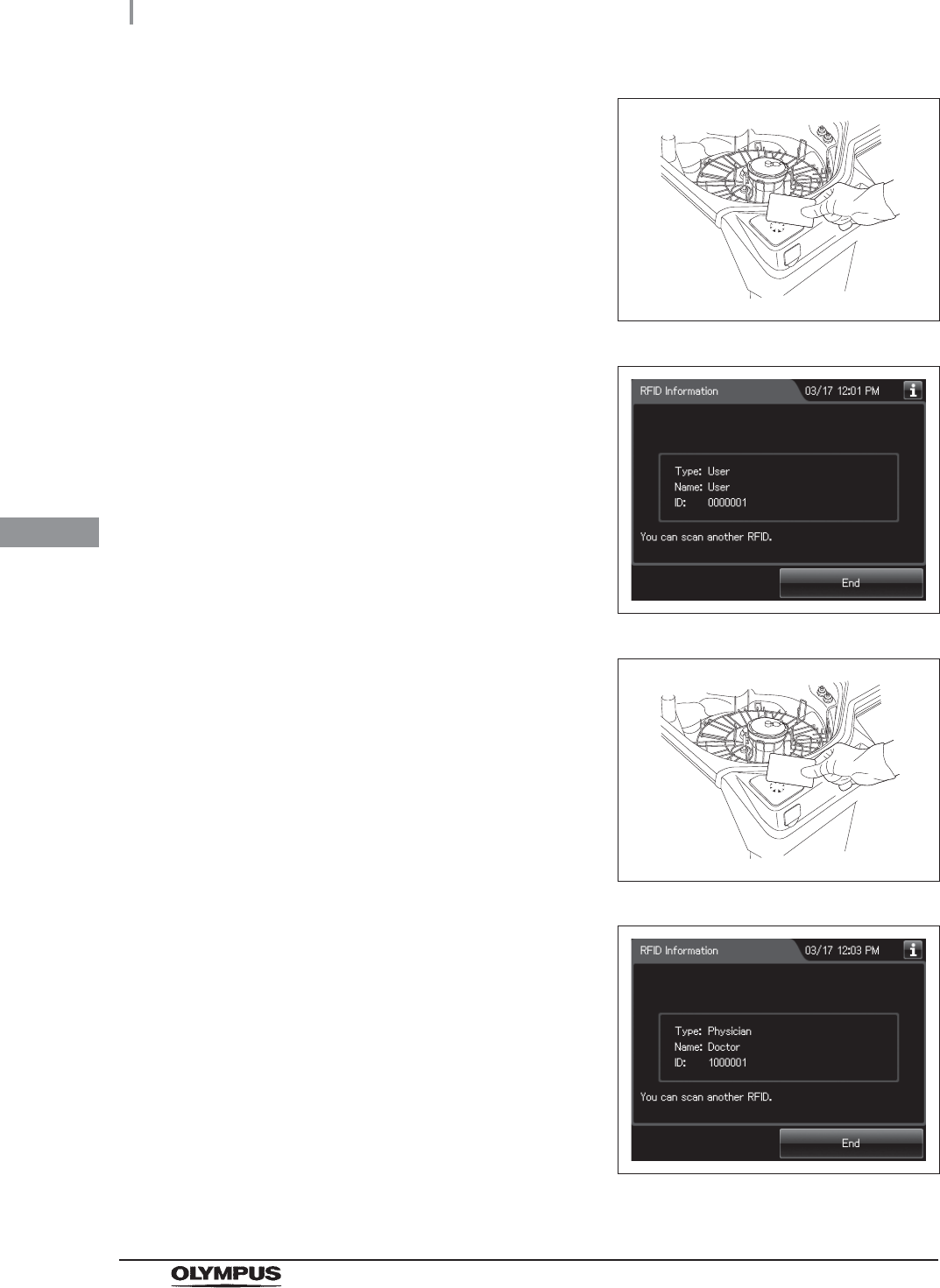
6Next, hold a User ID card parallel to the ID
reader and scan the card with the reader until
the equipment generates a short beep.
Figure 4.26
7The information on the User ID is displayed on
touch screen.
Figure 4.27
8Next, hold a physician ID card parallel to the ID
reader and scan the card with the reader until
the equipment generates a short beep.
Figure 4.28
9The information on the physician ID is
displayed the touch screen.
Figure 4.29
4.8 Inspection of the RFID function
73
OER-Elite INSTALLATION MANUAL
Ch.4
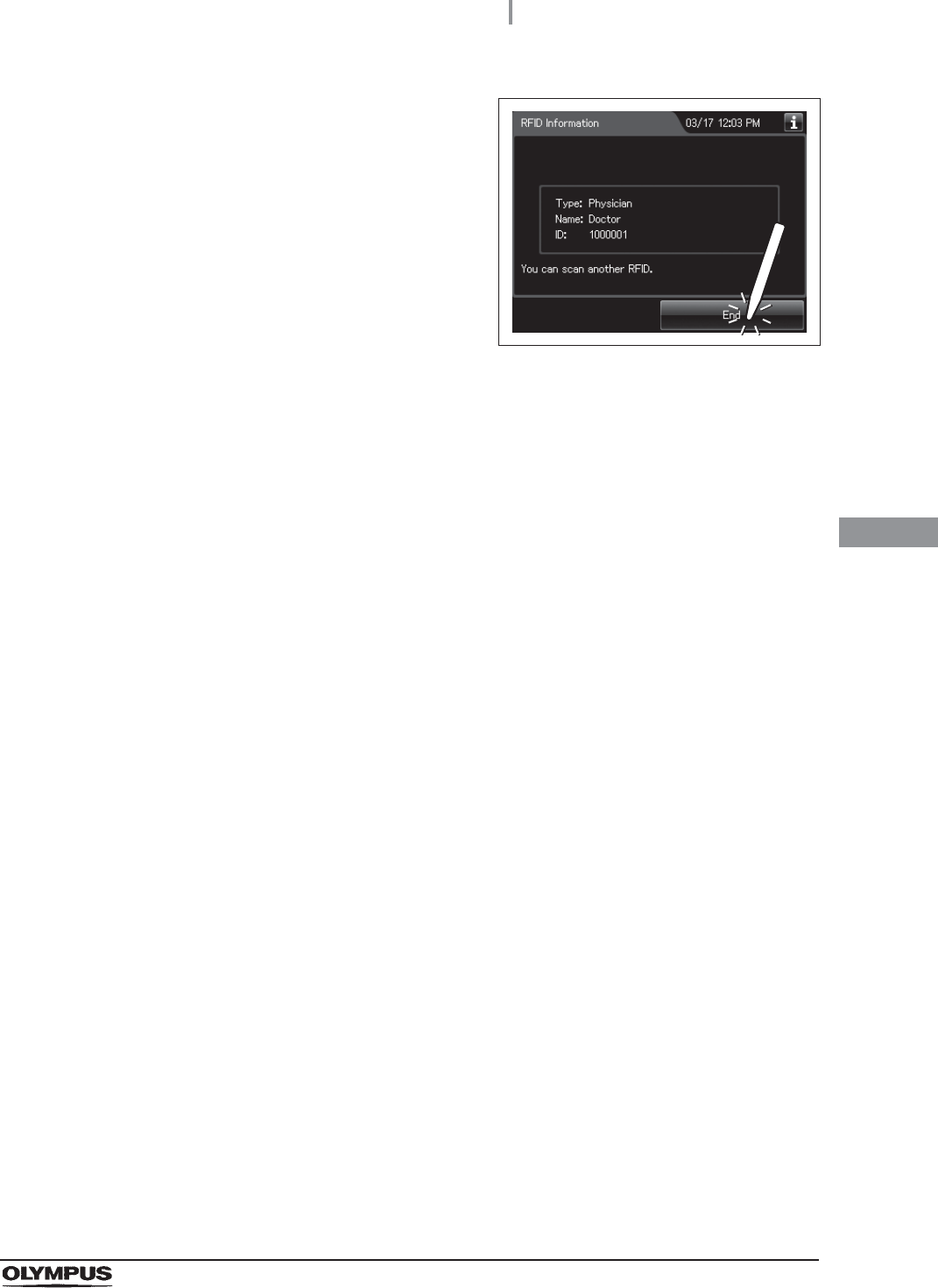
10 Press the “END” button to finish the RFID data
check.
Figure 4.30
74
4.9 Setting the date and time
OER-Elite INSTALLATION MANUAL
Ch.4
NOTE
• The built-in clock may gain or lose some time during use. In this case, adjust the
clock to the correct time using this function.
• Before changing the date setting, print records of the past stored in equipment by
using the print function.
• Records are stored according to the date and time.
• If there is the difference of date and time between that of equipment and that of
other connected equipment, adjust the clock to the correct time using this function.
Set the date and time on the built-in clock of the equipment.
4.9 Setting the date and time
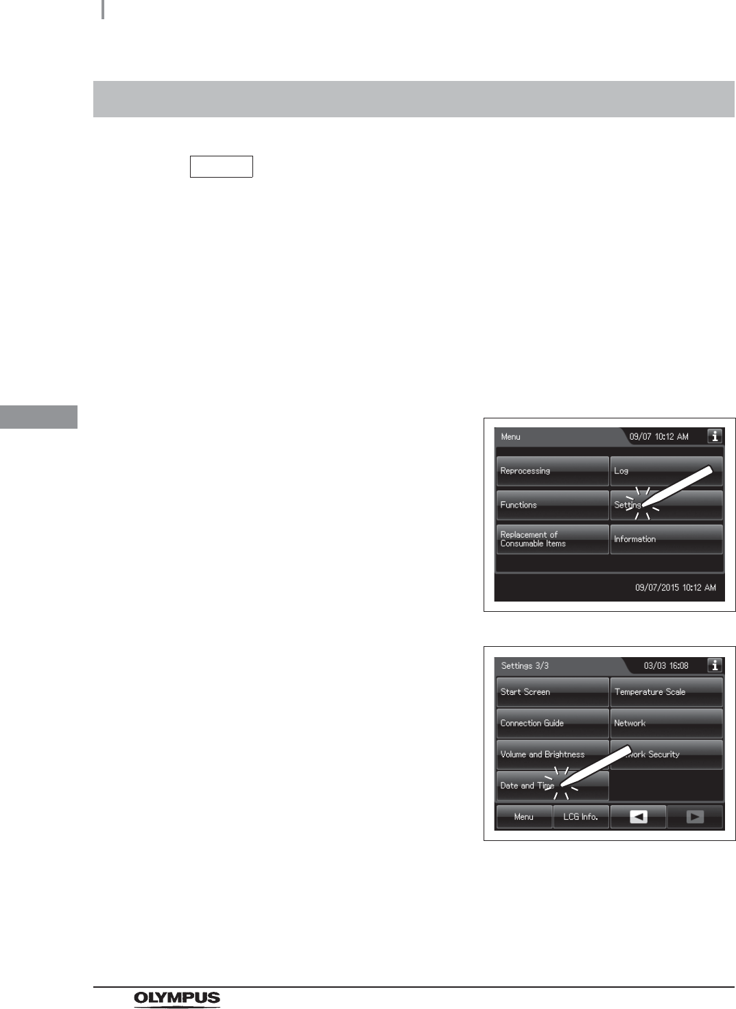
1Press the “Settings” button on the Menu
screen.
Figure 4.31
2Press the “Date and Time” button on the 3rd
page of the Settings menu.
Figure 4.32
4.9 Setting the date and time
75
OER-Elite INSTALLATION MANUAL
Ch.4
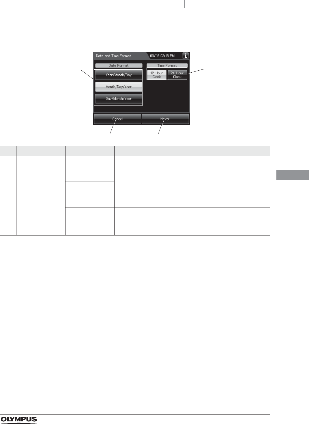
NOTE
The selected settings are displayed with white buttons.
3Select the date format and the time format, and then press the “Next” button.
No. Item/Button Setting options Description
1 Date Format Year/Month/Day Sets the format of the date display on the touch screen.
Month/Day/Year
(default)
Day/Month/Year
2 Time Format 12-hour clock
(default)
The hour is displayed in the 12-hour system, with “AM” for before
noon or “PM” for the afternoon.
24-hour clock The hour is displayed in the 24-hour system.
3 Cancel – Returns to the Setting menu without saving the edited information.
4 Next – Goes to the next setting.
1
3 4
2
76
4.9 Setting the date and time
OER-Elite INSTALLATION MANUAL
Ch.4
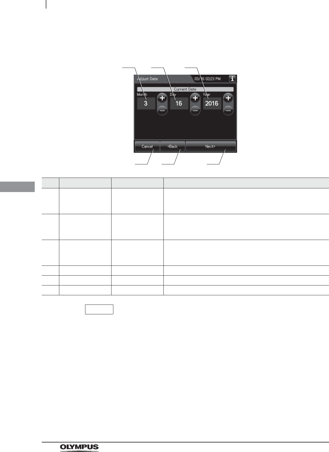
NOTE
The order of year, month, and day displayed on the screen depends on the date
format setting.
4Check and correct the date, and then press the “Next” button.
No. Item/Button Setting options Description
1 Month 1 – 12 Edit the figure of the current month.
Pressing the “+” button increments the setting and pressing the
“–” button decrements it.
2 Day 1 – 31 Edit the figure of the current day.
Pressing the “+” button increments the setting and pressing the
“–” button decrements it.
3 Year 2012 – 2087 Edit the figure of the current year.
Pressing the “+” button increments the setting and pressing the
“–” button decrements it.
4 Cancel – Returns to the Setting menu without saving the edited information.
5 Back – Returns to the previous screen.
6 Next – Goes to the next setting.
1
4 5 6
2 3
4.9 Setting the date and time
77
OER-Elite INSTALLATION MANUAL
Ch.4
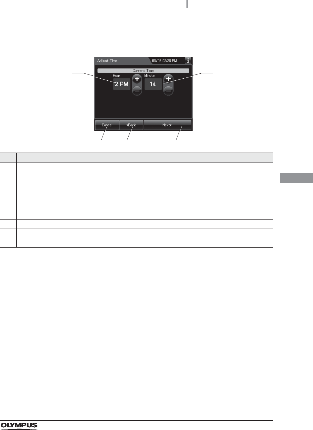
5Confirm or correct the time and press the “Next” button.
No. Item/Button Setting options Description
1 Hour 0 – 11
(12-hour clock)
0 – 23
(24-hour clock)
Edit the figure of the current hour.
Pressing the “+” button increments the setting and pressing the
“–” button decrements it.
2 Minute 0 – 59 Edit the figure of the current minute.
Pressing the “+” button increments the setting and pressing the
“–” button decrements it.
3 Cancel – Returns to the Setting menu without saving the edited information.
4 Back – Returns to the previous screen.
5 Next – Goes to the confirmation screen.
1
3 4
2
5
78
4.9 Setting the date and time
OER-Elite INSTALLATION MANUAL
Ch.4
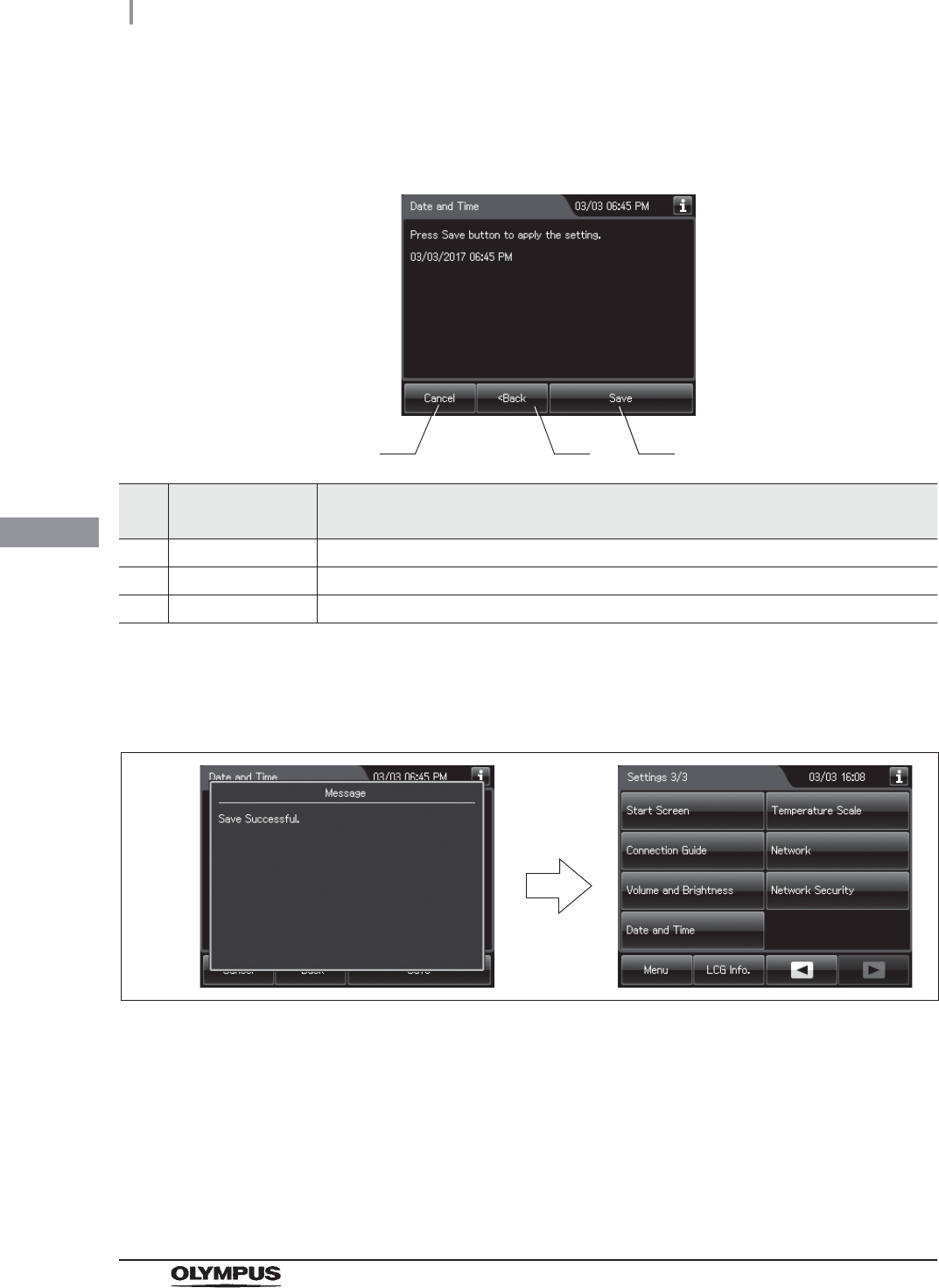
6Confirm the date and time and press the “Save” button to save the corrected date and
time.
No. Setting item/
Button Note
1 Cancel Returns to the Setting menu without saving the edited information.
2 Back Return to the previous screen.
3 Save Returns to the Setting menu after saving the edited information.
7When the date and time setting is completed, the touch screen displays the
completion message. The completion massage closes after a few seconds and the
Setting menu is displayed.
Figure 4.33
1 2 3
4.10 Installation of the gas filters (MAJ-822)
79
OER-Elite INSTALLATION MANUAL
Ch.4
The gas filter cases are designed to be attached to the lid and gas filter case mount for the disinfectant
tank. A gas filter (MAJ-822) should be placed in each of the two gas filter cases.
WARNING
• As individual reactions to the disinfectant solution may vary, Olympus recommends
the use of gas filters and enhanced protection by following the recommendations
on ventilation given in “Ensuring the safety of reprocessing personnel” on
page 11.
• Always be sure to attach the specified gas filter. Otherwise, the elimination of the
odor and vapor of the disinfectant solution may become insufficient.
CAUTION
Do not block the ventilation openings on the gas filter cases with the replacement
date indication sticker or any other label. Blocking the ventilation does not hinder
the deodorization effect but may cause the equipment to malfunction.
NOTE
The lot number of the gas filter can be recorded in the gas filter replacement
history. For changing the lot management of the gas filter, refer to Section 4.15,
“Filter lot number management” in “Instructions-Operation Manual”.
Required items
Table 4 . 1
4.10 Installation of the gas filters (MAJ-822)
Check Required items
Gas filter (MAJ-822) × 2
80
4.10 Installation of the gas filters (MAJ-822)
OER-Elite INSTALLATION MANUAL
Ch.4
Attachment of the gas filter case to the lid
1Prepare the gas filter
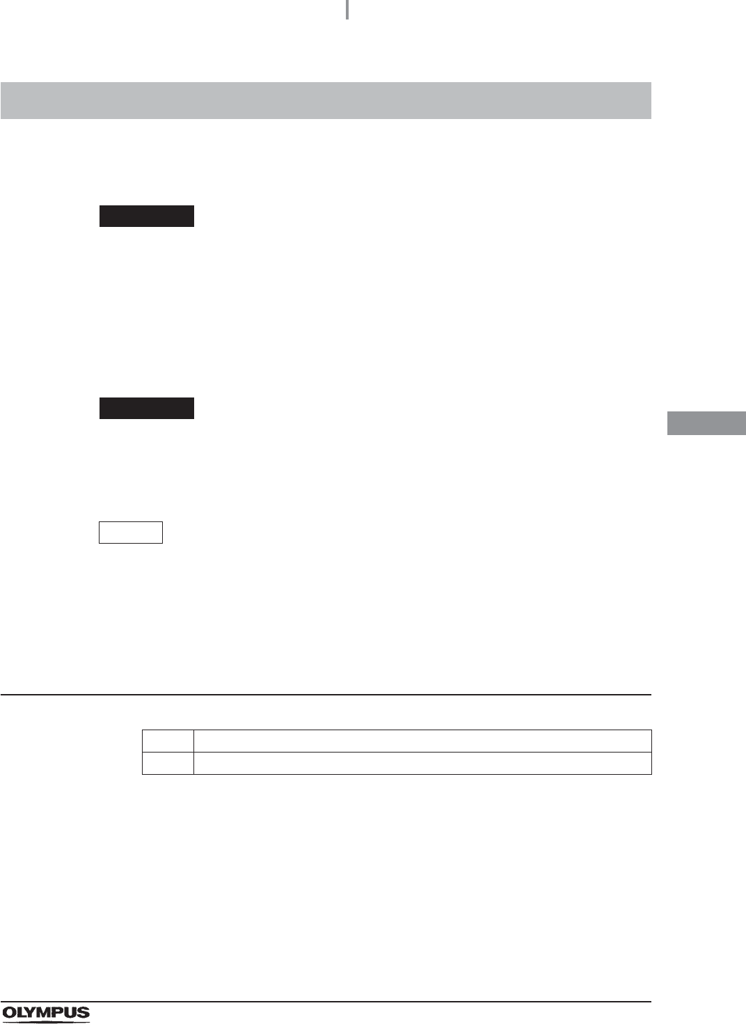
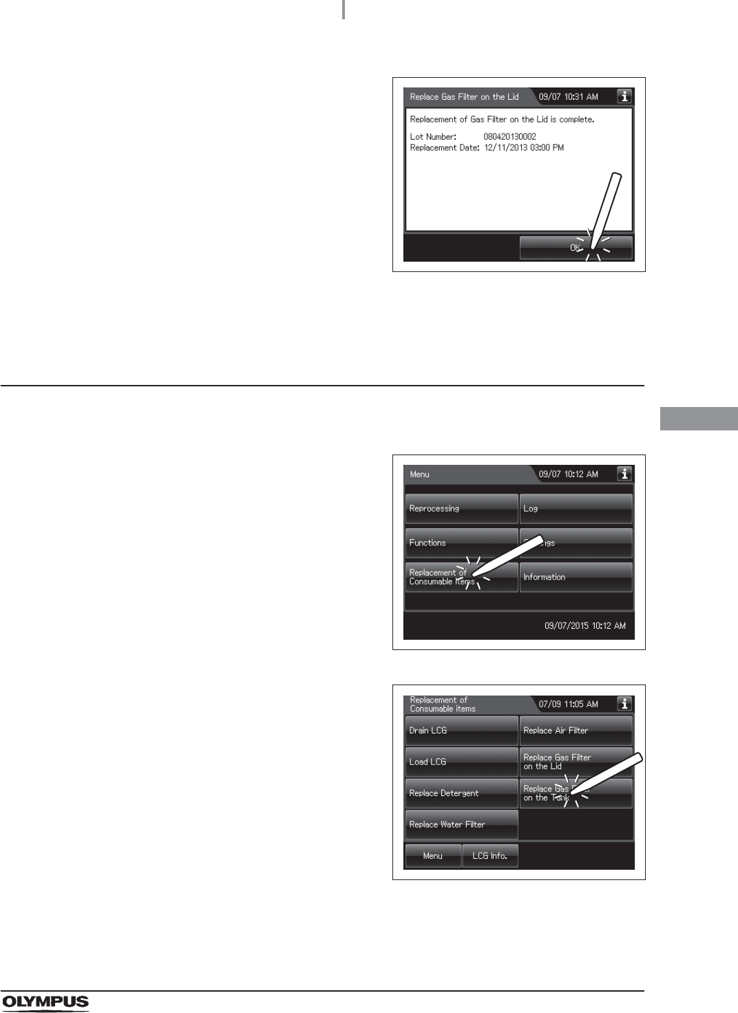
2Press the “Replacement of Consumable Items”
button on the Menu Screen.
Figure 4.34
3Press the “Replace Gas Filter on the Lid”
button.
Figure 4.35
4Enter the operator's user ID. For the detailed procedures, refer to Section 3.6,
“Entering ID” in “Instructions-Operation Manual” (If applicable).
Figure 4.36
When the User ID entered by RFID
When the User ID is entered by the
software keyboard or called from
registered users
4.10 Installation of the gas filters (MAJ-822)
81
OER-Elite INSTALLATION MANUAL
Ch.4
NOTE
• The input of the User ID can be omitted by modifying the User ID input setting. For
details, refer to Section 4.5, “User ID Setting” in “Instructions-Operation Manual”.
• If the “Delete” button is pressed, the entered ID can be deleted.
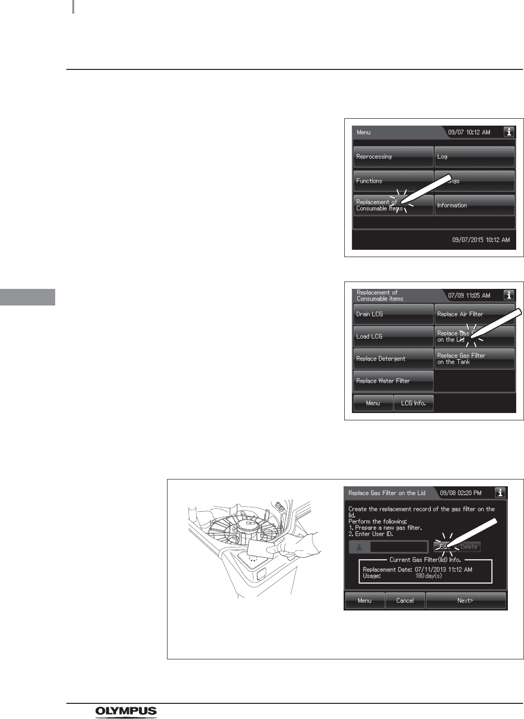
5Press the “Next” button.
Figure 4.37
NOTE
When the lot number management of the gas filter is activated, the lot number of
the gas filter is entered after Step 5. For details, refer to “When entering the lot
number of the gas filter” on page 87.
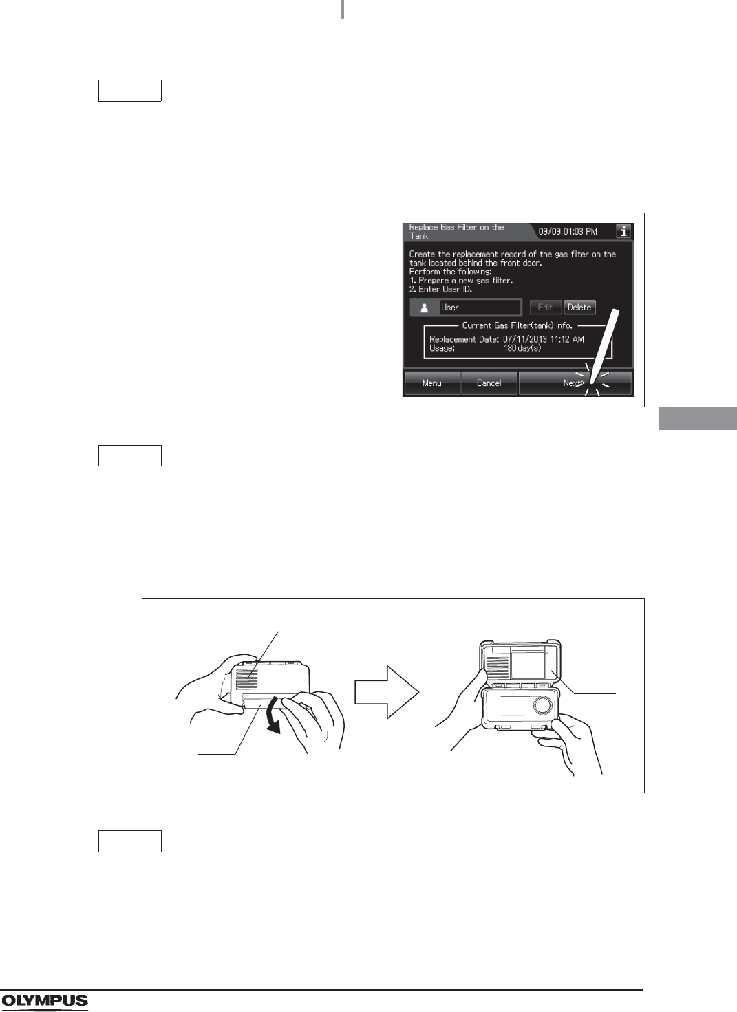
6Unlock each gas filter case cover and open it.
Figure 4.38
NOTE
The gas filters are not placed in the gas filter cases when the equipment is shipped
from the factory.
Ventilation opening
Lock
Cover
82
4.10 Installation of the gas filters (MAJ-822)
OER-Elite INSTALLATION MANUAL
Ch.4
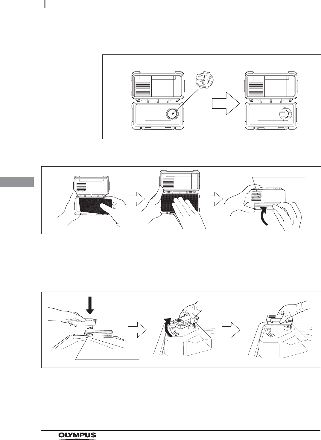
7Attach the gas filter adapter (splash guard) to the lid gas filter case as shown below so
that the water droplets from the reprocessing basin do not penetrate.
Figure 4.39
8Place a new gas filter in each gas filter case.
Figure 4.40
9Close and lock the cover. Do not to catch the gas filter when closing the cover.
10 Insert the gas filter case designed for the reprocessing basin (the one with gas filter
adapter (splash guard) attached to it) into the mount on the deep part of the lid, and
then turn it all the way in the direction shown below until it is stopped.
Figure 4.41
Gas filter adapter
(splash guard)
Ventilation opening
Gas filter case mount
4.10 Installation of the gas filters (MAJ-822)
83
OER-Elite INSTALLATION MANUAL
Ch.4
Attachment of the gas filter case to the disinfectant
solution tank
11 Press the “OK” button.
Figure 4.42
1Prepare the gas filter.
2Press the “Replacement of Consumable Items”
button on the Menu Screen.
Figure 4.43
3Press the “Replace Gas Filter on the Tank”
button.
Figure 4.44
84
4.10 Installation of the gas filters (MAJ-822)
OER-Elite INSTALLATION MANUAL
Ch.4
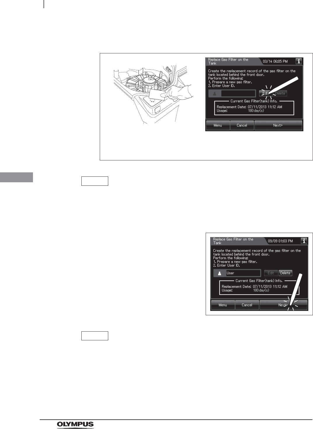
4Enter the operator's user ID. For the detailed procedures, refer to Section 3.6,
“Entering ID” in “Instructions-Operation Manual” (If applicable).
Figure 4.45
NOTE
• The input of the User ID can be omitted by modifying the User ID input setting. For
details, refer to Section 4.5, “User ID Setting” in “Instructions-Operation Manual”.
• If the “Delete” button is pressed, the entered ID can be deleted.
5Press the “Next” button.
Figure 4.46
NOTE
When the Lot management of the water filter is activated, the lot number of the
water filter is entered after Step 5. For details, refer to “When entering the lot
number of the gas filter” on page 87.
When the User ID entered by RFID
When the User ID is entered by the
software keyboard or called from
registered users
4.10 Installation of the gas filters (MAJ-822)
85
OER-Elite INSTALLATION MANUAL
Ch.4
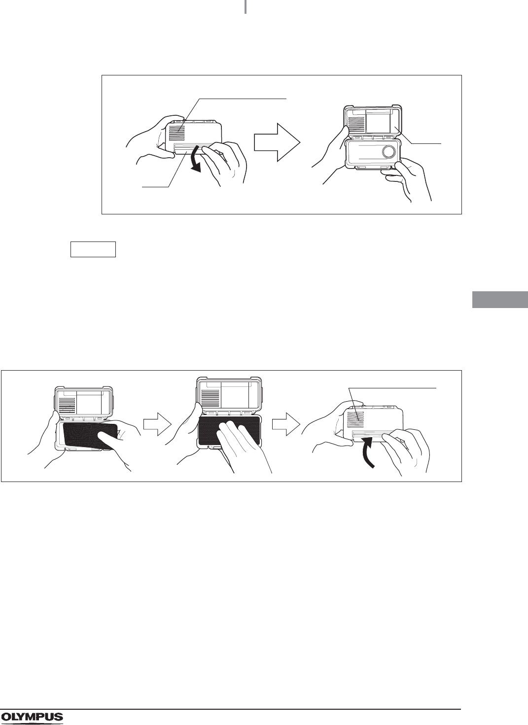
6Unlock each gas filter case cover and open it.
Figure 4.47
NOTE
• The gas filters are not placed in the gas filter cases when the equipment is shipped
from the factory.
• Do not attach the gas filter adapter (splash guard) to the disinfectant solution tank
gas filter case
7Place a new gas filter in each gas filter case.
Figure 4.48
8Close and lock the cover. Do not to catch the gas filter when closing the cover.
Ventilation opening
Lock
Cover
Ventilation opening
86
4.10 Installation of the gas filters (MAJ-822)
OER-Elite INSTALLATION MANUAL
Ch.4
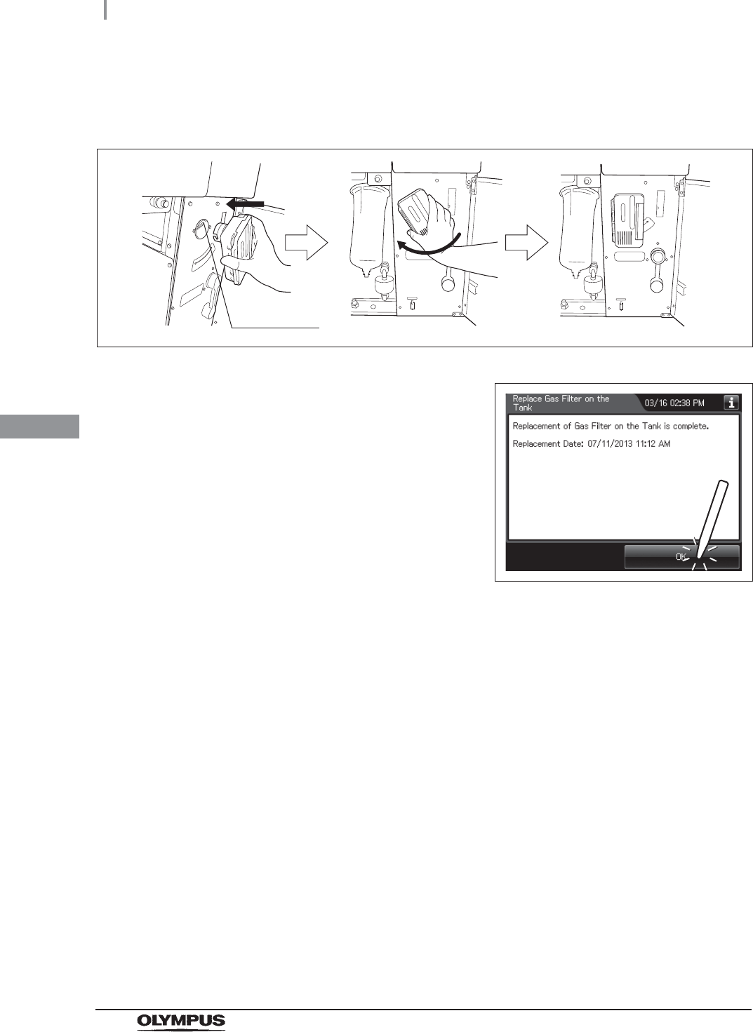
9Insert the gas filter case designed for the disinfectant solution tank into the gas filter
case mount at the top right of the inside of the front door, and then turn it all the way in
the direction shown below until it is stopped.
Figure 4.49
10 Press the “OK” button.
Figure 4.50
Gas filter
case mount
4.10 Installation of the gas filters (MAJ-822)
87
OER-Elite INSTALLATION MANUAL
Ch.4
When entering the lot number of the gas filter
If the Lot management is activated, enter the Lot number according to the following procedure.
NOTE
The Lot number is printed on a label affixed to the package containing the gas filter.
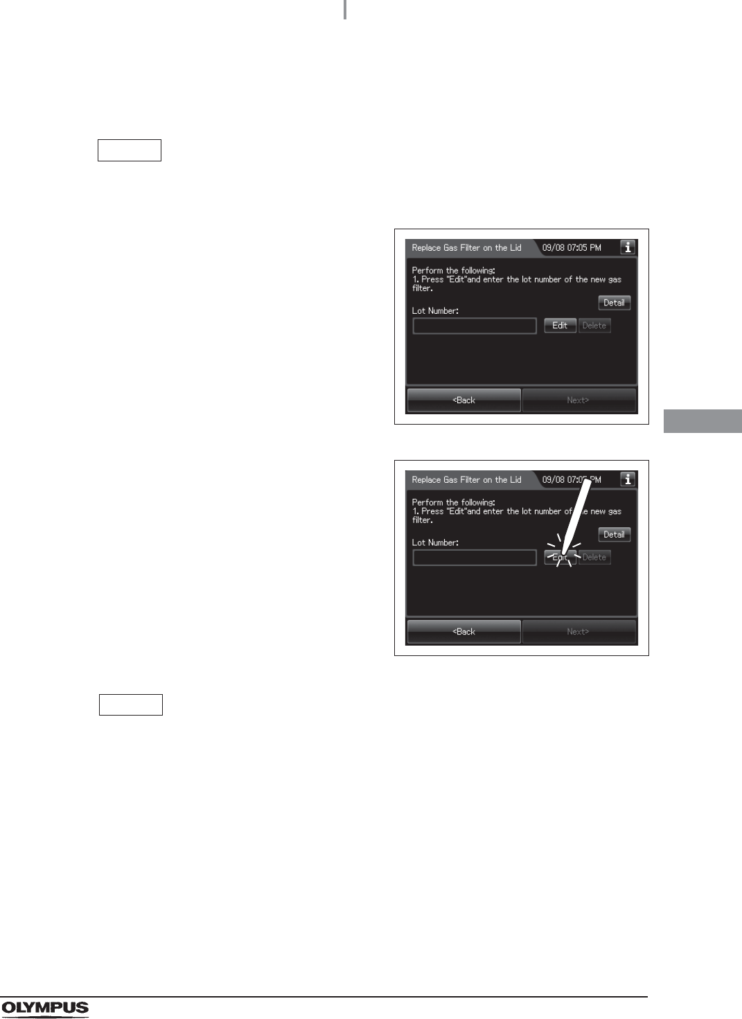
1If the filter lot number management of the gas
filter (Lid and/or Tank) is active, the touch
screen displays a screen as shown in following
figure after Step 6 in “Attachment of the gas
filter case to the lid” on page 81 or Step 5 in
“Attachment of the gas filter case to the
disinfectant solution tank” on page 84. Press the
“Next” button.
Figure 4.51
2Press the “Edit” button to display the lot entry
screen.
Figure 4.52
NOTE
If the “Delete” button is pressed, the entered Lot No can be deleted.
88
4.10 Installation of the gas filters (MAJ-822)
OER-Elite INSTALLATION MANUAL
Ch.4
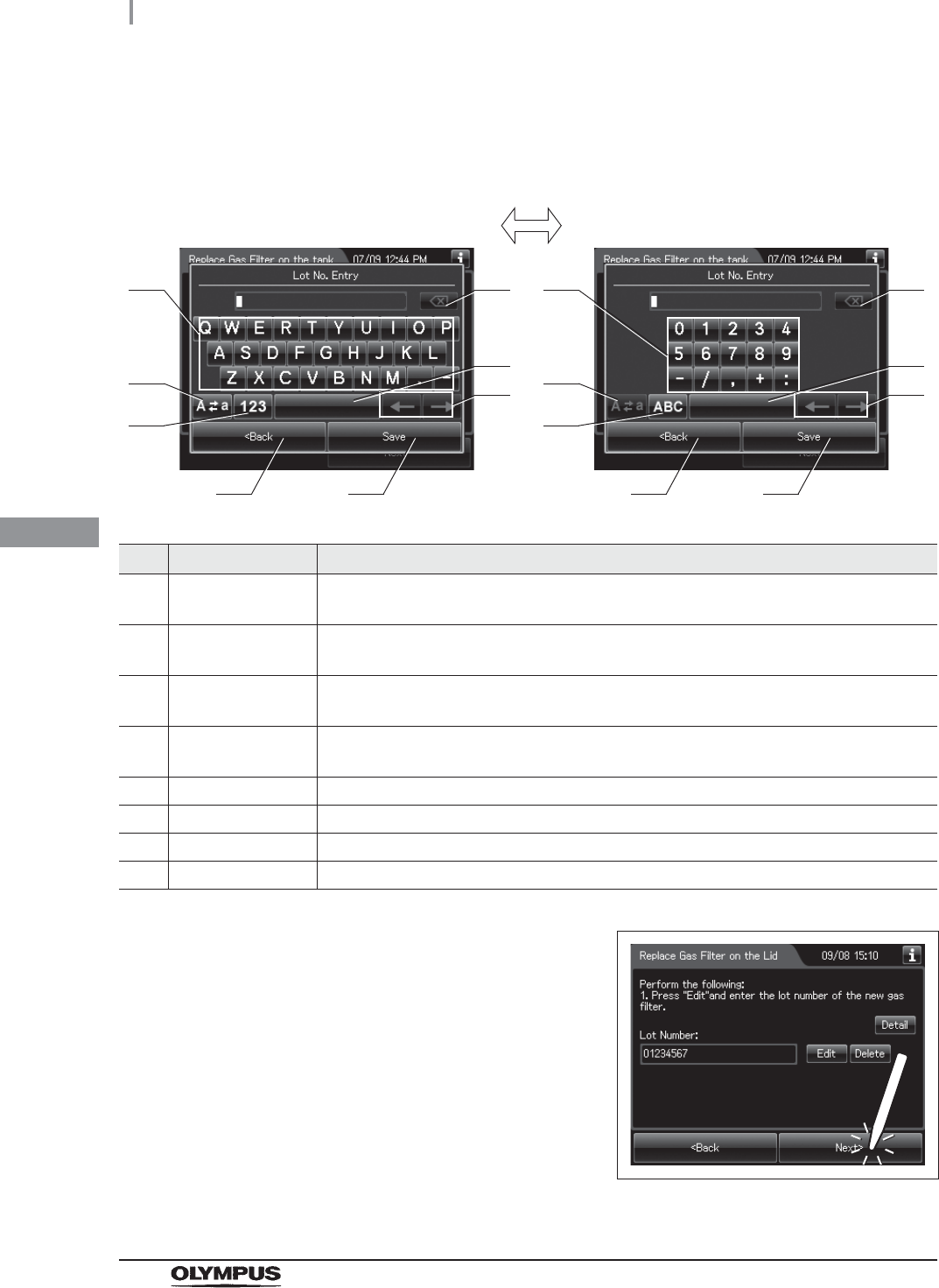
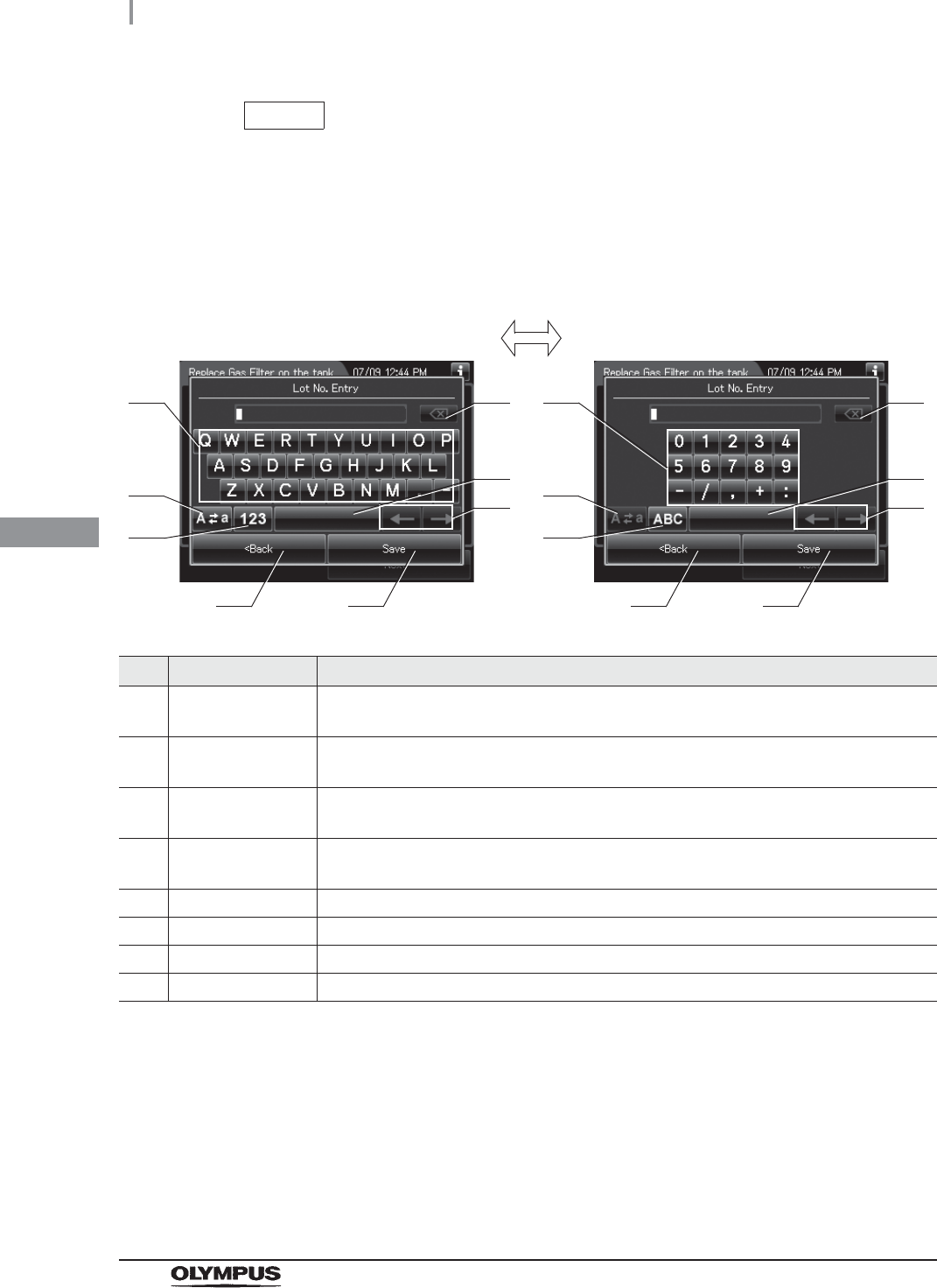
3Enter the lot number of the new gas filter by the software keyboard on the touch
screen and press the “Save” button.
No. Button Note
1 Alphabet/Numeral
key
Enter the alphabet or a numeral.
2 Uppercase/Lowerc
ase button
Press “Uppercase/lowercase button” to switch alphabet character on the soft keyboard
between uppercases character s and lowercase characters.
3 Numeric/Alphabetic
button
Press “Numeric or Alphabetic button” to switch the input mode between a numeral and
the alphabet.
4 Back space button Press the “Backspace button” to delete the left character of a cursor.
When a cursor is on the leftmost, this button becomes gray and cannot be pressed.
5 Space button Press to the “Space button” to insert a space character.
6 Cursor move button Press to the cursor move button to move a cursor to left or right.
7 Back button Return to the previous screen without saving the setting value.
8 Save button Return to the previous screen and save the entered value.
4Press the “Next” button.
Figure 4.53
41
2
3
5
6
7 8
41
2
3
5
6
7 8
Alphabet input Numeral input
4.10 Installation of the gas filters (MAJ-822)
89
OER-Elite INSTALLATION MANUAL
Ch.4
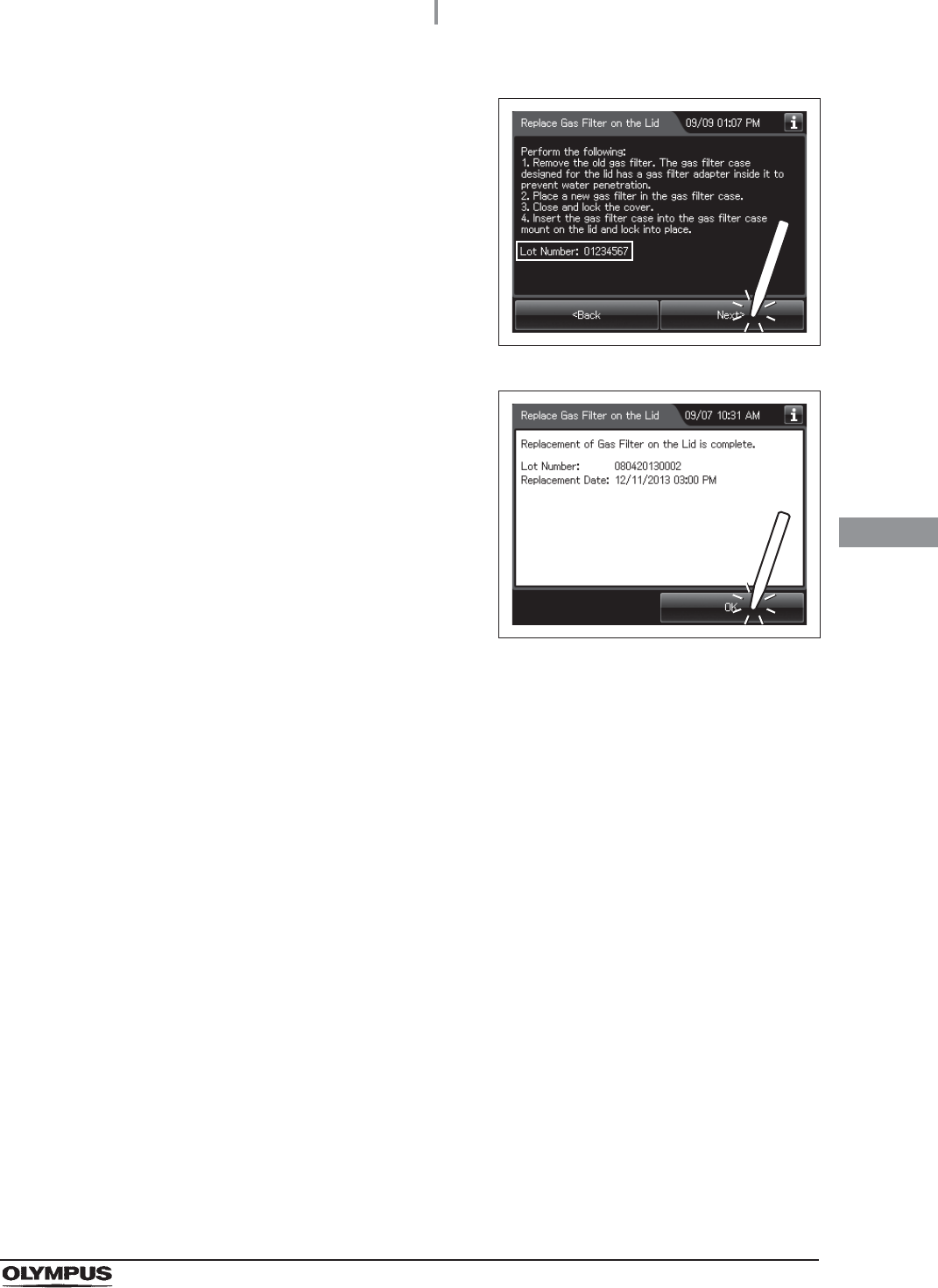
5Check the displayed lot number and press the
“Next” button.
Figure 4.54
6Press the “OK” button.
Figure 4.55
90
4.11 Installation of the air filter (MAJ-823)
OER-Elite INSTALLATION MANUAL
Ch.4
The air filter is used to remove miscellaneous bacteria and fine particles from the air.
When the air filter is installed in the following procedure, the record of air filter replacements can be
stored in memory.
WARNING
• Always be sure to attach the specified air filter. Otherwise, the air may contaminate
the equipment piping and/or the scope and prevent effective reprocessing.
• Replace the air filter at least every month. If the performance of the air filter drops,
insufficient elimination of miscellaneous bacteria in air may cause contamination of
the instrument and scopes and make the reprocessing insufficient.
NOTE
• When the air filter counter setting is activated, the filter replacement indicator can
be displayed on the top right of the touch screen and on the “Replace Air Filter”
button on the Replacement of Consumable Items menu when the counter setting
value is reached.
• The lot number of the air filter can be recorded in the air filter replacement history.
For changing the lot management of the air filter, refer to Section 4.15, “Filter lot
number management” in “Instructions-Operation Manual”.
Required items
Table 4.2
4.11 Installation of the air filter (MAJ-823)
Check Required items
Air filter (MAJ-823)
4.11 Installation of the air filter (MAJ-823)
91
OER-Elite INSTALLATION MANUAL
Ch.4
Installing the air filter
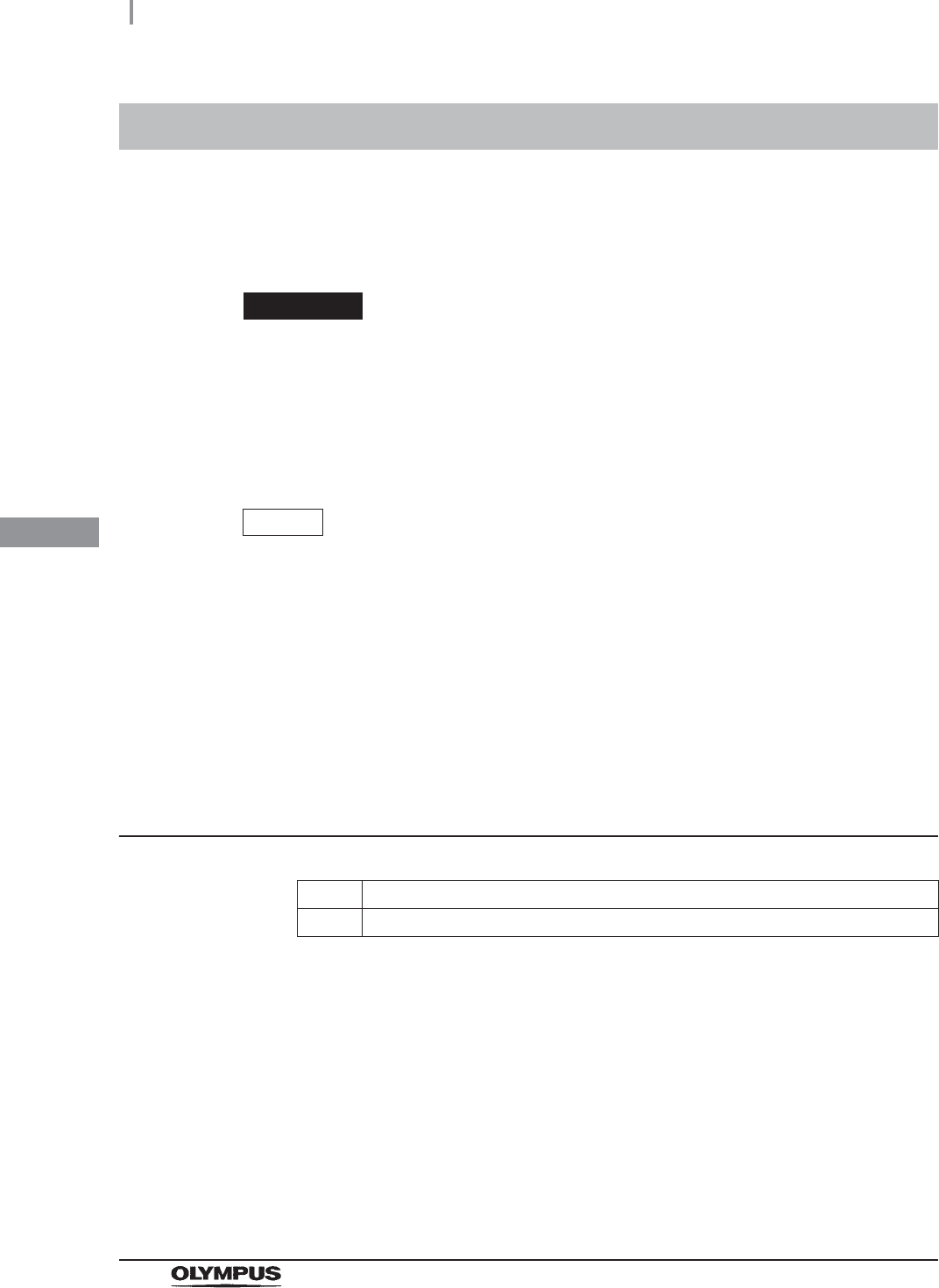
1Prepare the air filter.
2Press the “Replacement of Consumable items”
button on the Menu screen.
Figure 4.56
3Press the “Replace Air Filter on the Lid” button.
Figure 4.57
4Enter the operator's user ID. For the detailed procedures, refer to Section 3.6,
“Entering ID” in “Instructions-Operation Manual” (If applicable).
Figure 4.58
When the User ID entered by RFID
When the User ID is entered by the
software keyboard or called from
registered users
92
4.11 Installation of the air filter (MAJ-823)
OER-Elite INSTALLATION MANUAL
Ch.4
NOTE
• The input of the User ID can be omitted by modifying the User ID input setting. For
details, refer to Section 4.5, “User ID Setting” in “Instructions-Operation Manual”.
• If the “Delete” button is pressed, the entered ID can be deleted.
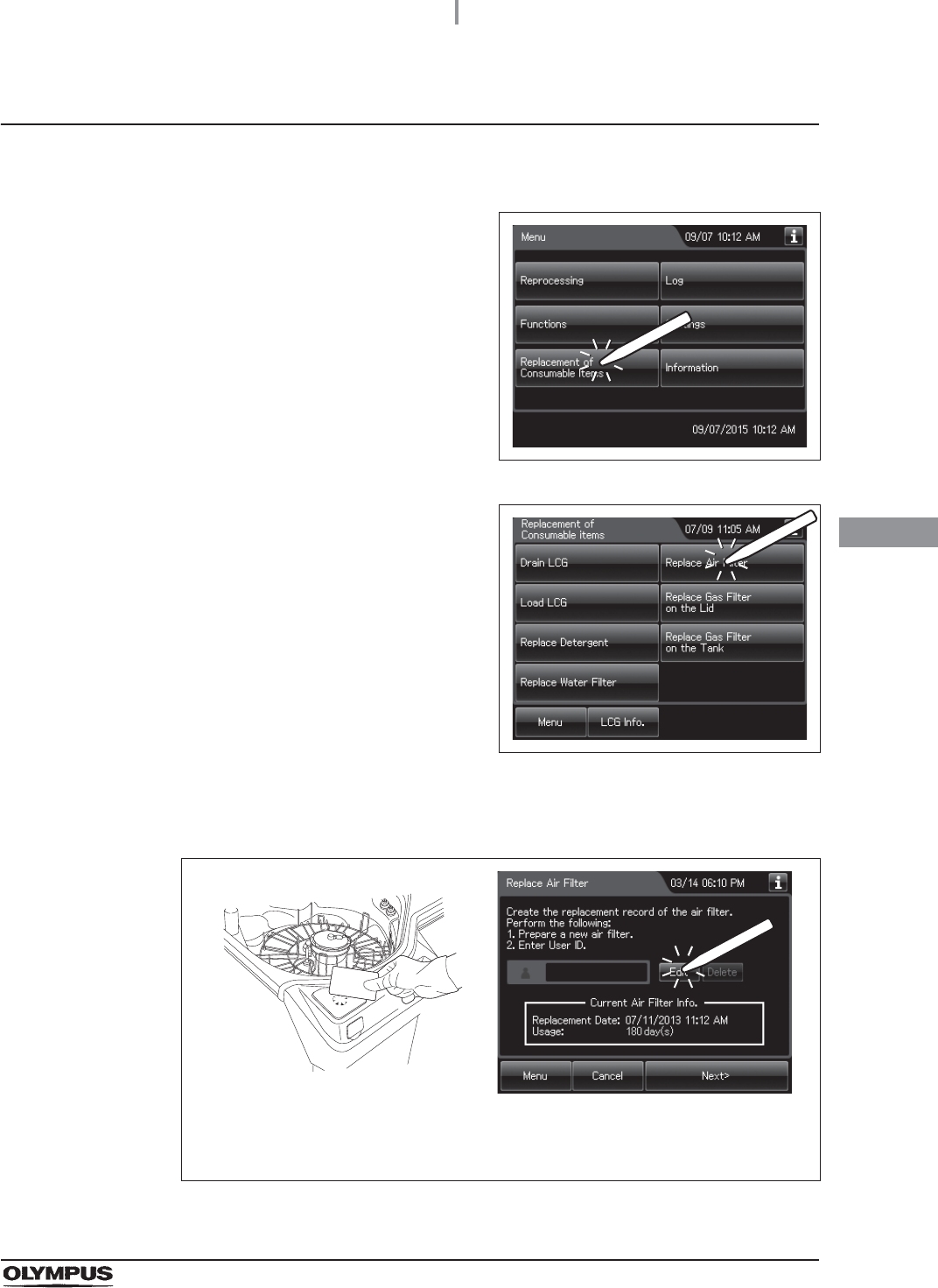
5Open the front door of the device.
NOTE
The air filter is not installed on the device when it is shipped from the factory.
6With the FLOW indicator pointing upwards,
attach a new air filter by fitting into the two
connectors until they click.
Figure 4.59
7Press the “Next” button.
Figure 4.60
NOTE
When the lot management of the air filter is activated, the lot number of the air filter
is entered after step 4. For details, refer to “When entering the lot number of the
air filter:” on page 93.
4.11 Installation of the air filter (MAJ-823)
93
OER-Elite INSTALLATION MANUAL
Ch.4
When entering the lot number of the air filter:
If the Lot management is activated, enter the Lot number according to the following procedure.
NOTE
The Lot number is printed on a label affixed to the package containing the air filter.
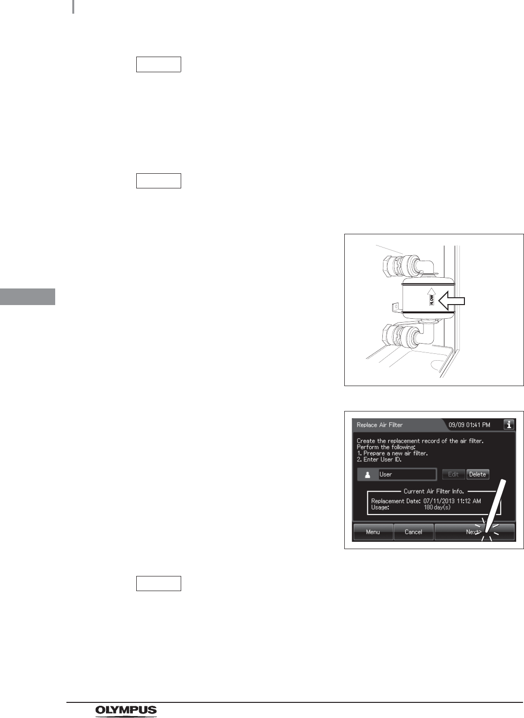
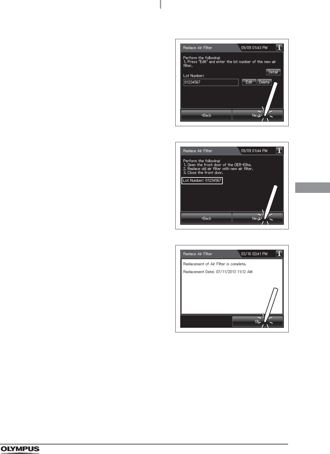
8Press the “OK” button to finish.
Figure 4.61
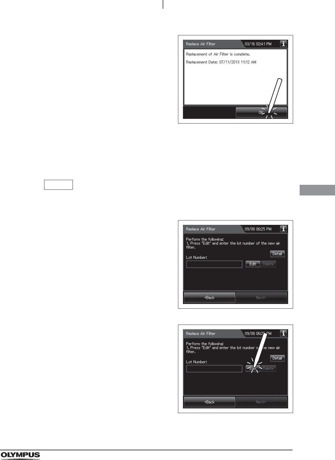
1If the filter lot number management of the air
filter is active, the touch screen displays a
screen as shown in following figure after Step 7
in “Installing the air filter” on page 91.
Figure 4.62
2Press the “Edit” button to display the lot entry
screen.
Figure 4.63
94
4.11 Installation of the air filter (MAJ-823)
OER-Elite INSTALLATION MANUAL
Ch.4
NOTE
If the “Delete” button is pressed, the entered Lot No can be deleted.
3Enter the lot number of the new air filter by the software keyboard on the touch screen
and press the “Save” button.
No. Button Note
1 Alphabet/Numeral
key
Enter the alphabet or a numeral.
2 Uppercase/Lowerc
ase button
Press “Uppercase/lowercase button” to switch alphabet character on the soft keyboard
between uppercases character s and lowercase characters.
3 Numeric/Alphabetic
button
Press “Numeric or Alphabetic button” to switch the input mode between a numeral and
the alphabet.
4 Back space button Press the “Backspace button” to delete the left character of a cursor.
When a cursor is on the leftmost, this button becomes gray and cannot be pressed.
5 Space button Press to the “Space button” to insert a space character.
6 Cursor move button Press to the cursor move button to move a cursor to left or right.
7 Back button Returns to the previous screen without saving the setting value.
8 Save button Returns to the previous screen and save the entered value.
41
2
3
5
6
7 8
41
2
3
5
6
7 8
Alphabet input Numeral input
4.11 Installation of the air filter (MAJ-823)
95
OER-Elite INSTALLATION MANUAL
Ch.4
4Press the “Next” button.
Figure 4.64
5Check the displayed lot number and press the
“Next” button.
Figure 4.65
6Press the “OK” button.
Figure 4.66
96
4.12 Inspection of air leakage from the air filter connectors
OER-Elite INSTALLATION MANUAL
Ch.4
Check that air is not leaking from the air filter connectors.
4.12 Inspection of air leakage from the air filter
connectors
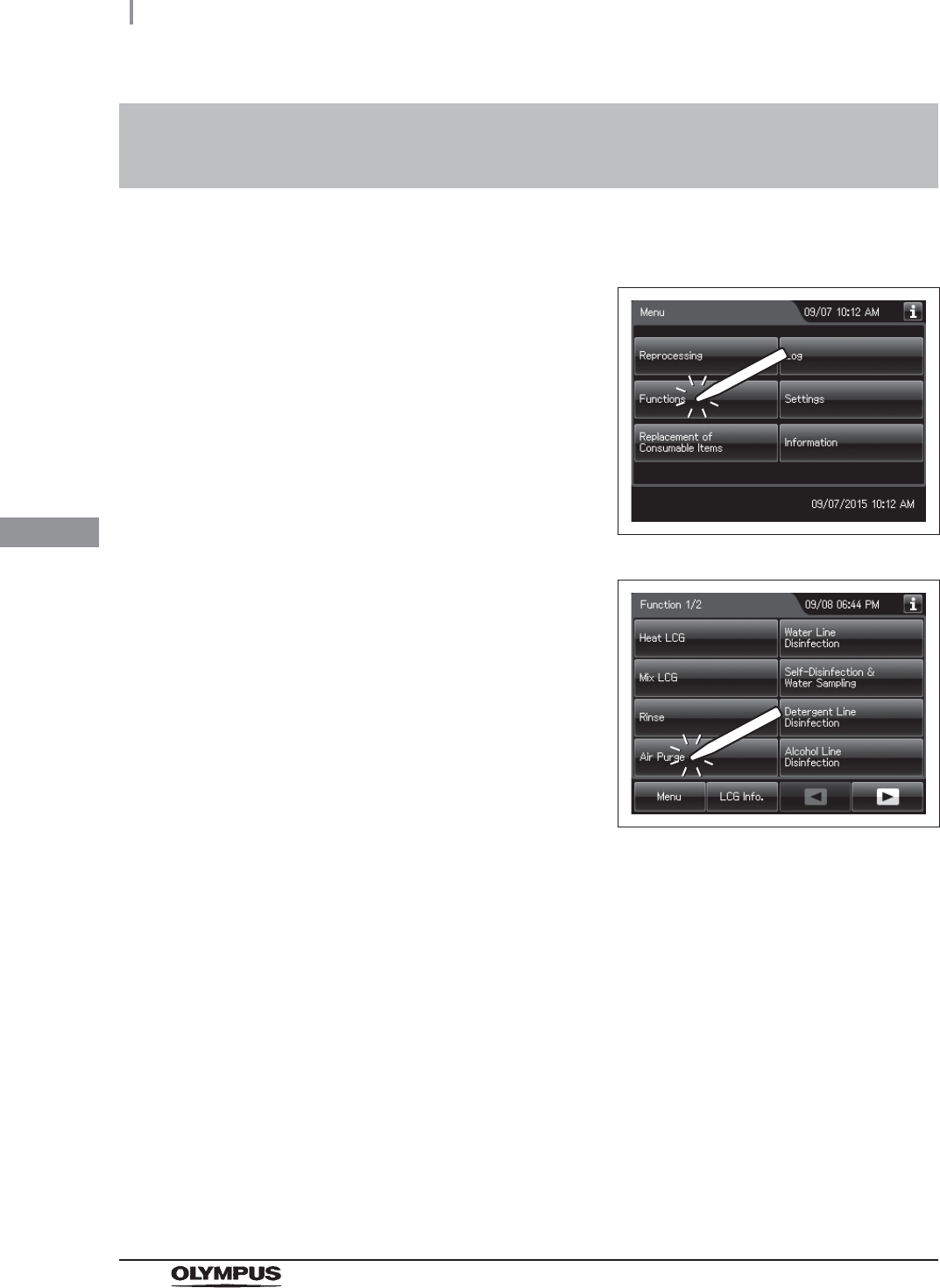
1Press the “Functions” button on the Menu
screen.
Figure 4.67
2Press the “Air Purge” button.
Figure 4.68
4.12 Inspection of air leakage from the air filter connectors
97
OER-Elite INSTALLATION MANUAL
Ch.4
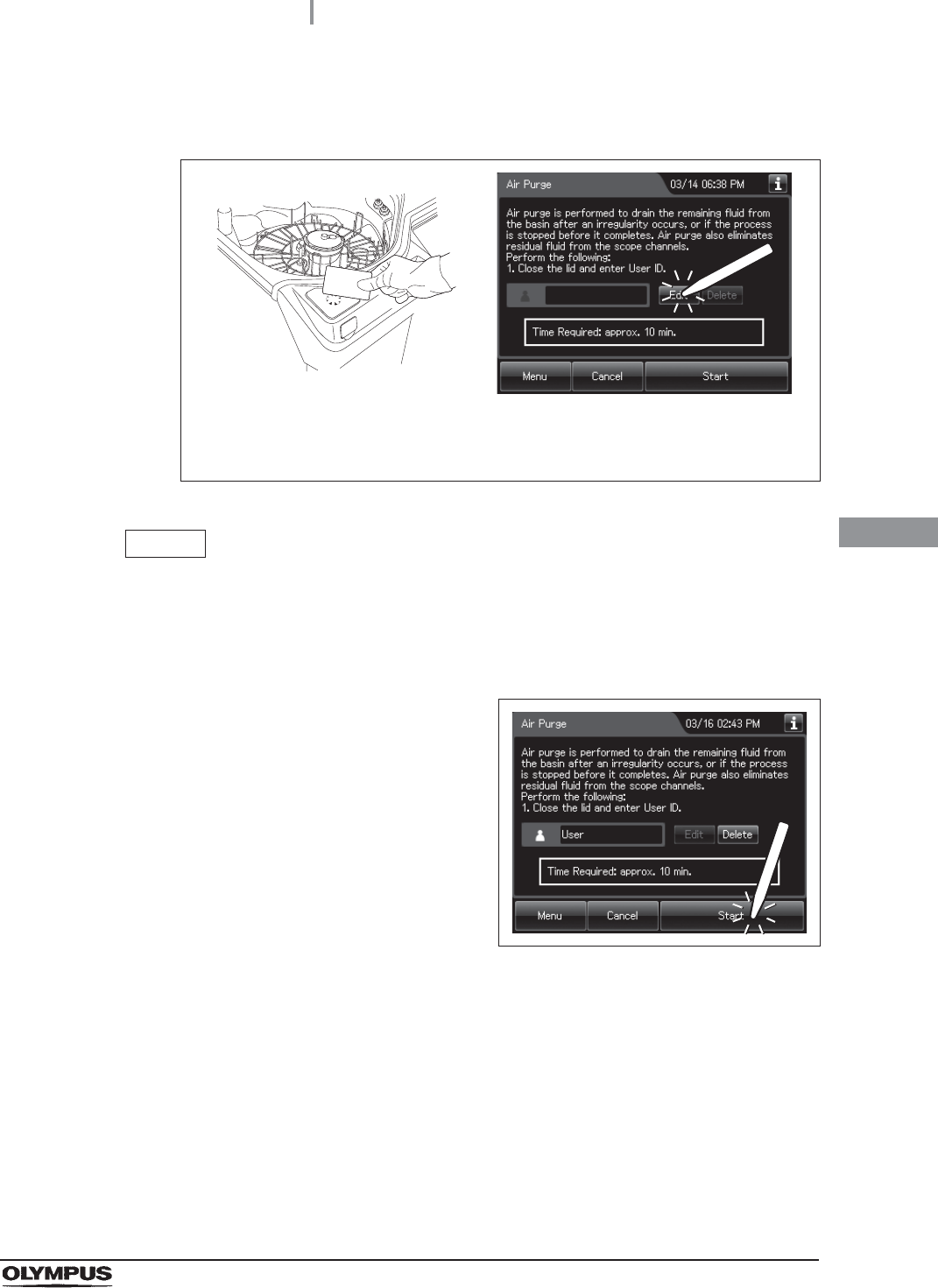
3Enter the operator's user ID. For the detailed procedures, refer to Section 3.6,
“Entering ID” in “Instructions-Operation Manual” (If applicable).
Figure 4.69
NOTE
• The input of the User ID can be omitted by modifying the User ID input setting. For
details, refer to Section 4.5, “User ID Setting” in “Instructions-Operation Manual”.
• If the “Delete” button is pressed, the entered ID can be deleted.
4Press the “Start” button.
Figure 4.70
5Open the front door of the equipment.
When the User ID entered by RFID
When the User ID is entered by the
software keyboard or called from
registered users
98
4.12 Inspection of air leakage from the air filter connectors
OER-Elite INSTALLATION MANUAL
Ch.4
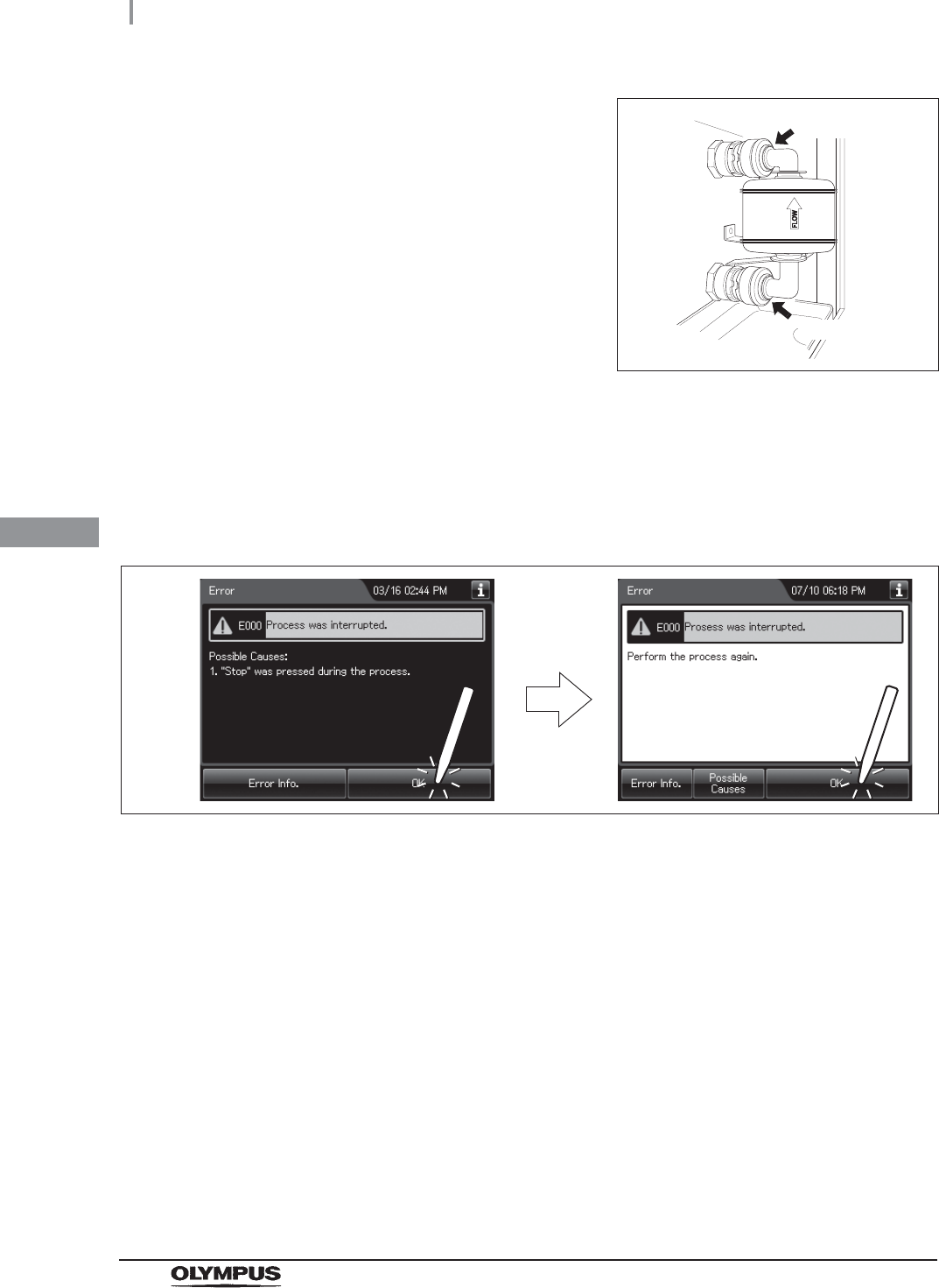
6When air purge has started, touch the air filter
connectors to ensure that air is not leaking out.
Also, ensure that the connectors do not
produce a whistling sound, which would mean
there is an air leak.
Figure 4.71
7Press the “Stop” button on the touch screen to end Air Purge. If an air Leak is
detected, reinstall the air filter as described in refer to “Replacing the air filter” in
Section 8.5, “Replacing the air filter (MAJ-823)” in “Instructions-Operation Manual”.
8The touch screen displays the error code [E000]. Press the “OK” button repeatedly
until the error screen is closed.
Figure 4.72
Connector
Connector
4.13 Installation of the water tray
99
OER-Elite INSTALLATION MANUAL
Ch.4
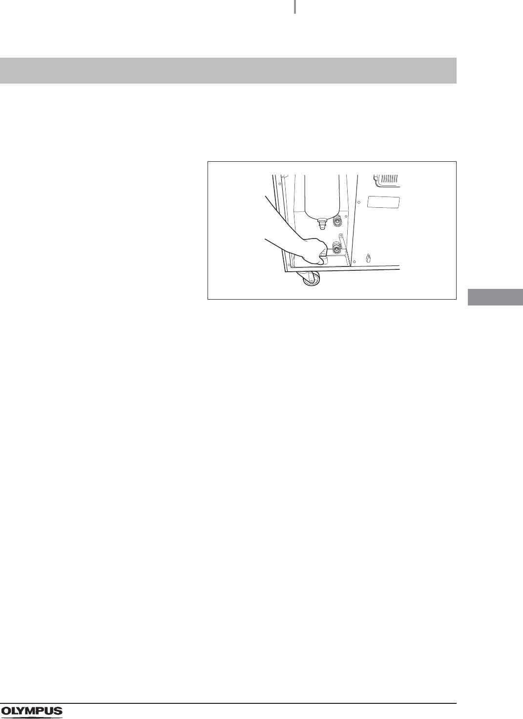
The water tray is used to receive and hold water during maintenance such as water filter replacement.
Push [PUSH] on the front door of the equipment to open the front door and place the water tray below
the water filter.
Figure 4.73
4.13 Installation of the water tray

100
4.14 Installation of the water filter (MAJ-824 or MAJ-2318)
OER-Elite INSTALLATION MANUAL
Ch.4
The water filter is bacteria-retentive.
When the water filter is installed in the following procedure, the record of water filter changes can be
stored in memory.
WARNING
• Attach the water filter under clean conditions. Do not touch the inner side of the
water filter. Otherwise, dust could get on it.
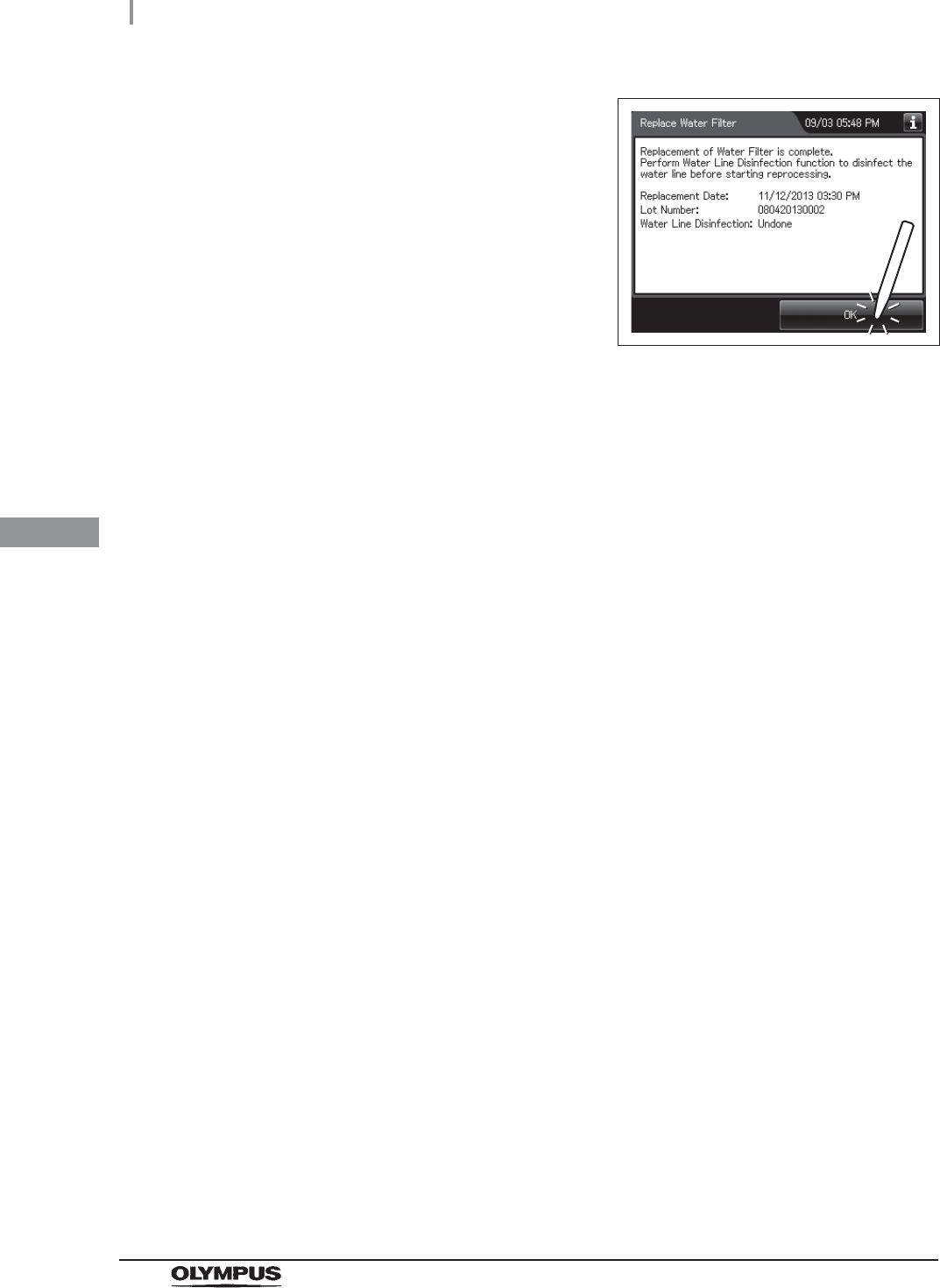
• After replacing the water filter, be sure to perform the operation described in
Section 4.22, “Water line disinfection” to prevent contaminating the water supply
pipes. Failure to perform this operation could result in contamination of the
equipment piping and/or the endoscope, preventing effective reprocessing.
• Always be sure to attach the water filter. Otherwise, the water may contaminate the
equipment piping and/or the endoscope and prevent effective reprocessing.
• Always be sure to use the specified water filter. Otherwise, the water may
contaminate the equipment piping and/or the endoscope and prevent effective
reprocessing.
CAUTION
• Hold the water filter wrench at a point below the projection on the grip. If you hold it
at a point closer to the water filter housing connector than the projection, you might
catch your finger in the equipment.
• After attaching the water filter, be sure to discharge air from the water filter housing
completely. If air is left in the water filter housing, the process time may be
extended. Check for air in the housing whenever the process time is extended or
other irregularities are noticed.
• Do not to drop the removed water filter housing. Otherwise, the water filter housing
and/or the connector below the water filter housing case may be cracked or
damaged and cause water leak.
• Make sure that the O-ring at the head of the water filter housing is free of
irregularities such as cracks, breaks, rips, scratches, or stains. Water leakage may
result if the O-ring is not attached or is abnormal.
4.14 Installation of the water filter (MAJ-824 or
MAJ-2318)
4.14 Installation of the water filter (MAJ-824 or MAJ-2318)
101
OER-Elite INSTALLATION MANUAL
Ch.4
NOTE
The lot number of the water filter can be recorded in the water filter replacement
history. For changing the lot management of the water filter, refer to Section 4.15,
“Filter lot number management” in “Instructions-Operation Manual”.
Required items
Table 4 . 3
Attachment of the water filter
Check Required items
Water filter (MAJ-824 or MAJ-2318)
Water filter wrench
Filter tubes (× 2)
Container with 2 L or larger capacity (wide-mouthed container such as a vat)
1Make sure that the water faucet is open.
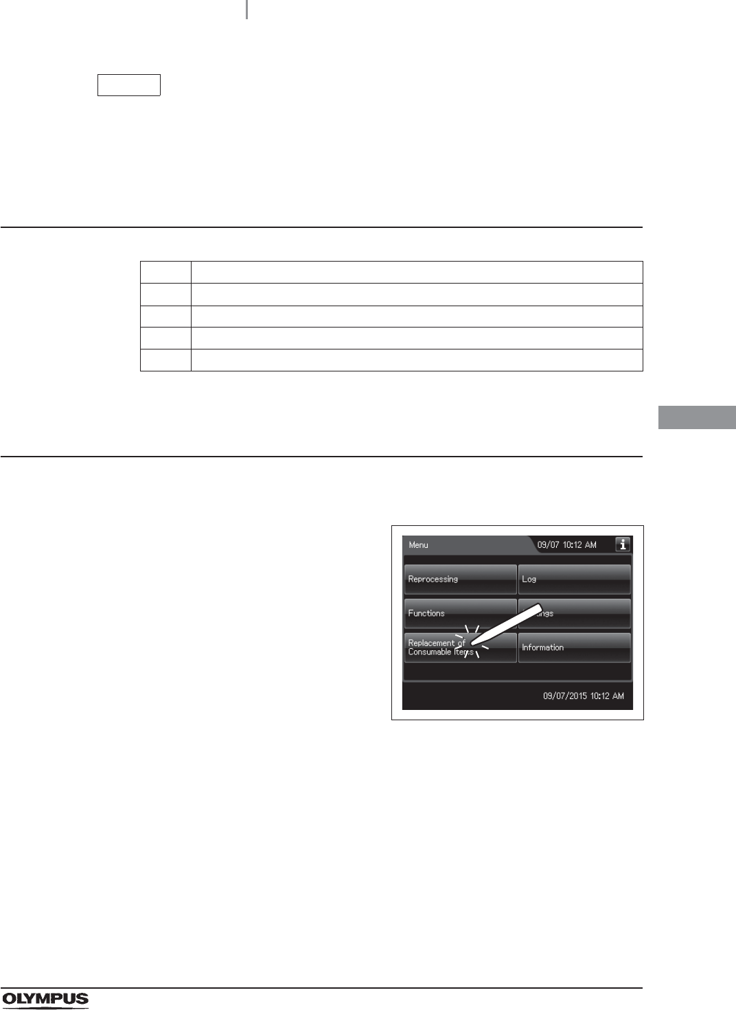
2Press the “Replacement of Consumable Items”
button on the Menu Screen.
Figure 4.74
102
4.14 Installation of the water filter (MAJ-824 or MAJ-2318)
OER-Elite INSTALLATION MANUAL
Ch.4
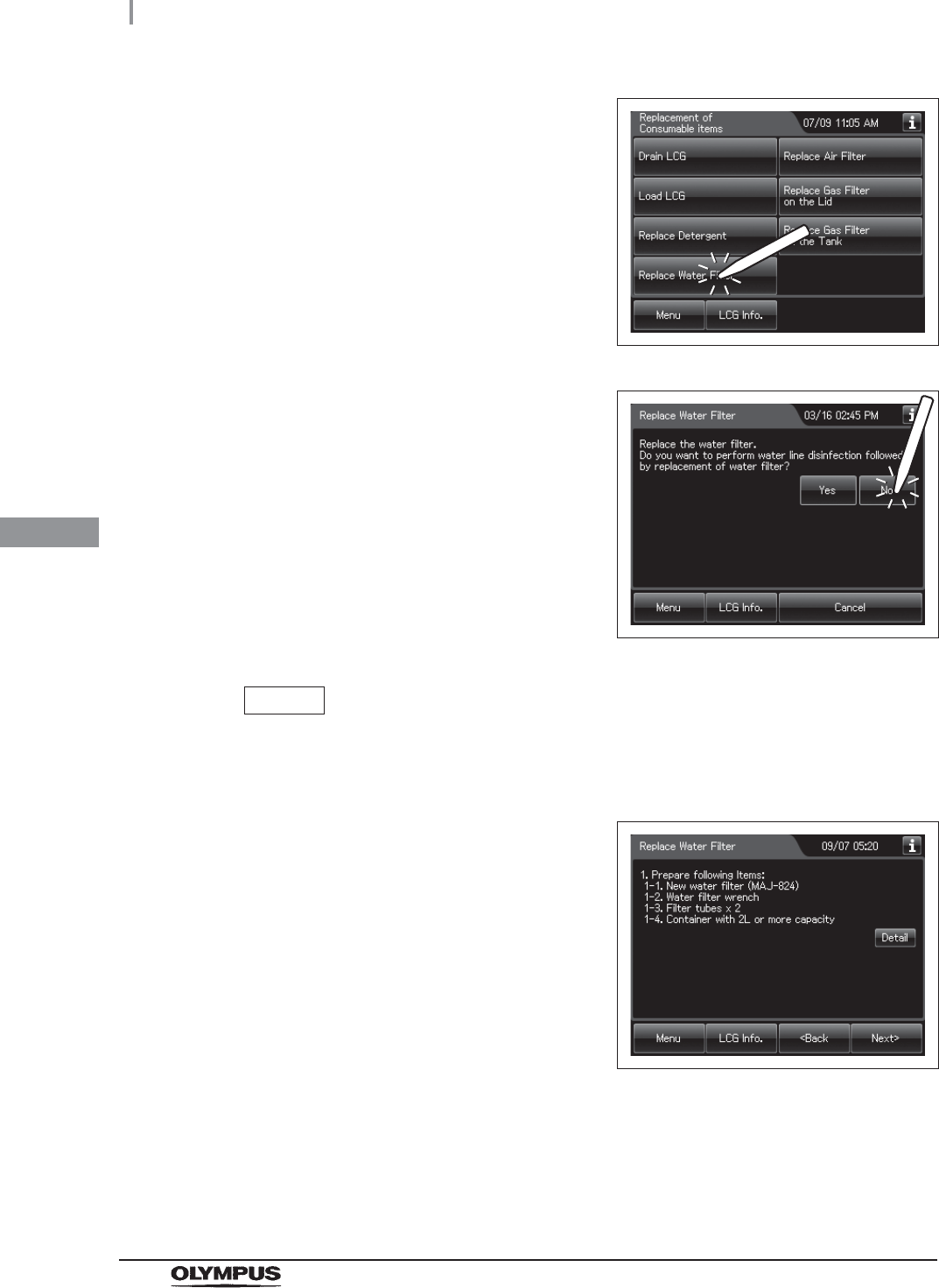
3Press the “Replace Water Filter” button.
Figure 4.75
4Press the “No” button.
Figure 4.76
NOTE
The disinfection of water supply piping is performed in Section 4.21, “Disinfection
of the water supply piping”.
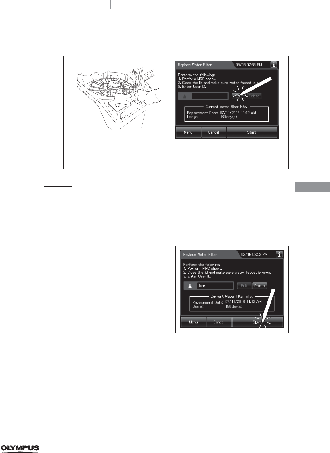
5Press the “Next” button repeatedly until the
touch screen display changes as shown below.
Figure 4.77
4.14 Installation of the water filter (MAJ-824 or MAJ-2318)
103
OER-Elite INSTALLATION MANUAL
Ch.4
6Enter the operator's user ID. For the detailed procedures, refer to Section 3.6,
“Entering ID” in “Instructions-Operation Manual” (If applicable).
Figure 4.78
NOTE
• The input of the User ID can be omitted by modifying the User ID input setting. For
details, refer to Section 4.5, “User ID Setting” in “Instructions-Operation Manual”.
• If the “Delete” button is pressed, the entered ID can be deleted.
7Press the “Start” button.
Figure 4.79
NOTE
When the Lot management of the water filter is activated, the lot number of the
water filter is entered after Step 7. For details, refer to “When entering the lot
number of the water filter” on page 111
When the User ID entered by RFID
When the User ID is entered by the
software keyboard or called from
registered users
104
4.14 Installation of the water filter (MAJ-824 or MAJ-2318)
OER-Elite INSTALLATION MANUAL
Ch.4
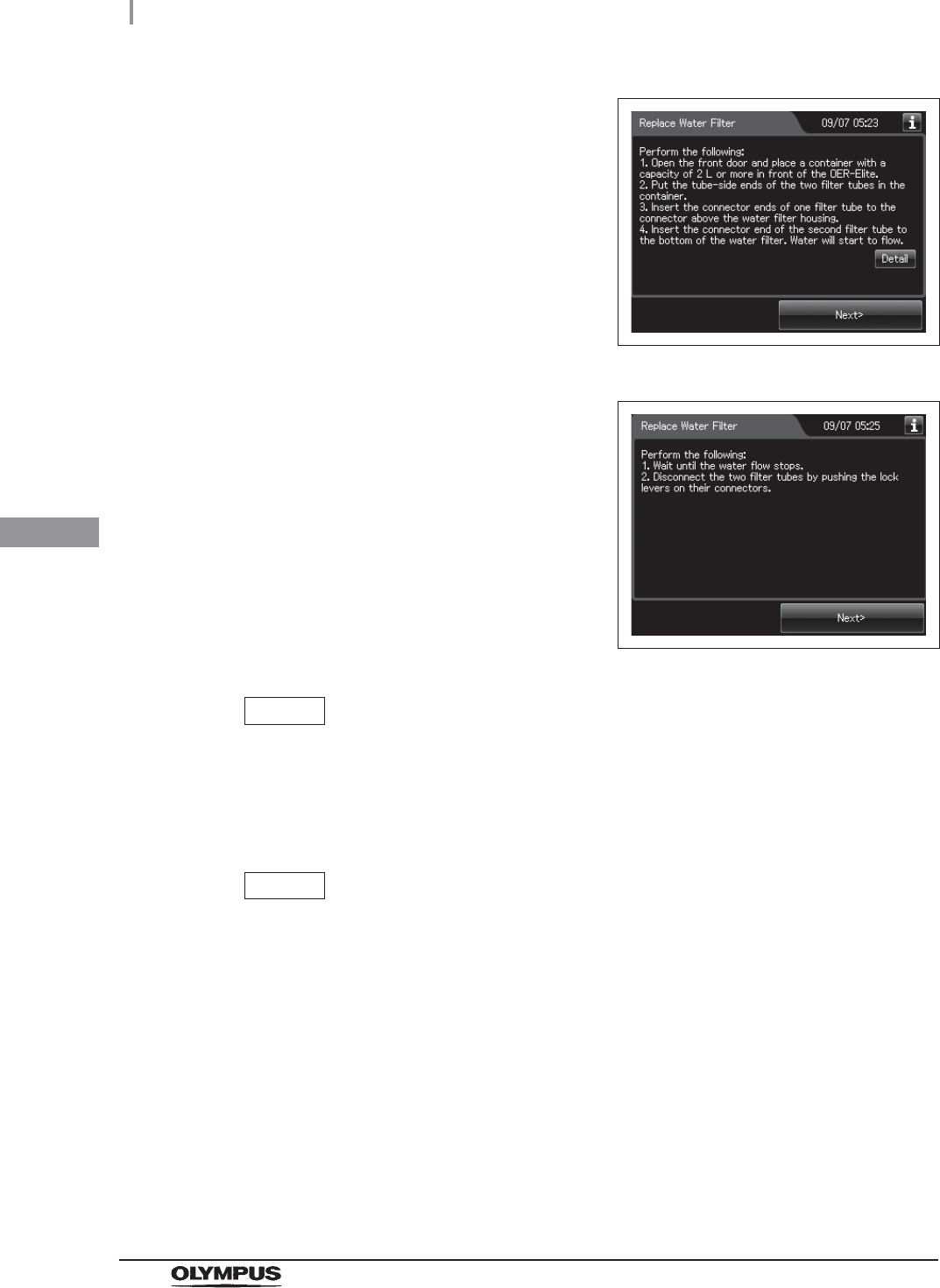
8Press the “Next” button repeatedly until the
touch screen display changes as shown below.
Figure 4.80
Figure 4.81
NOTE
If the “Detail” button is pressed, the details of work can be displayed on the touch
screen.
9Push the area marked “PUSH” on the front door to open it.
NOTE
Hold the water filter wrench at a point closer to you than to the projection on the
grip. If you hold it at a point closer to the water filter housing connector than the
projection, you might catch your finger in the mechanism.
4.14 Installation of the water filter (MAJ-824 or MAJ-2318)
105
OER-Elite INSTALLATION MANUAL
Ch.4
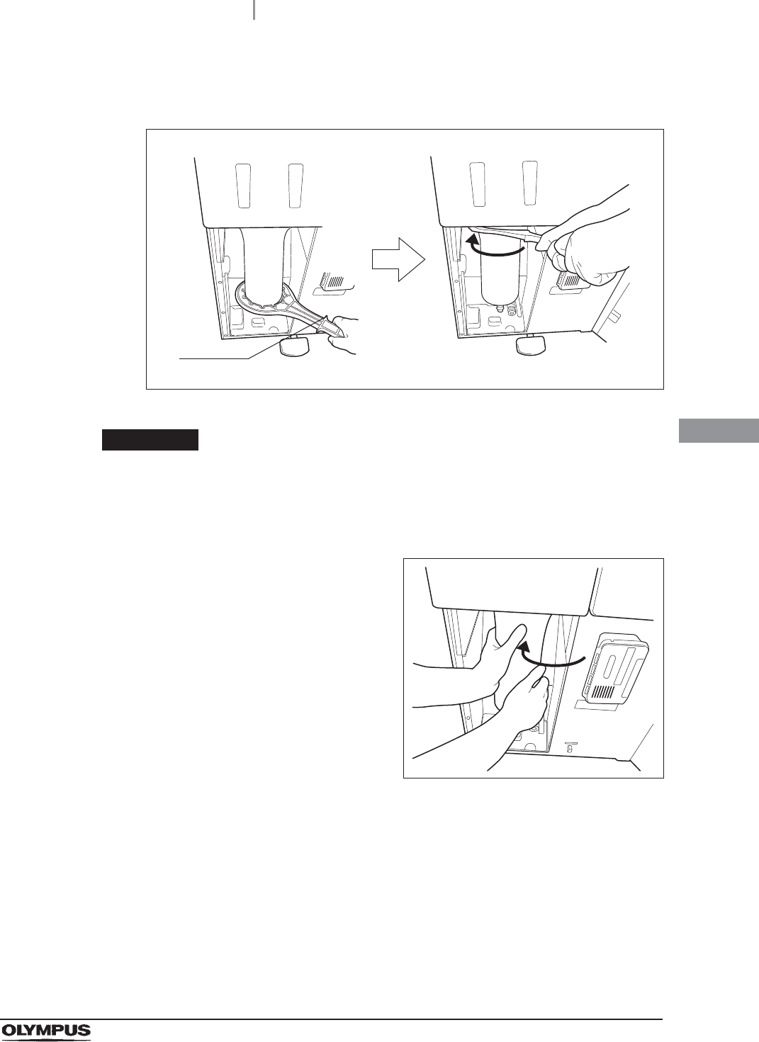
10 Insert the water filter wrench from below the water case and rotate the tool as shown
below to loosen the water filter housing.
Figure 4.82
CAUTION
After fully loosening the water filter housing with the attaching/detaching tool, hold
it with both hands and remove it. If the case is not fully loosened, your hands may
slip and you could be injured.
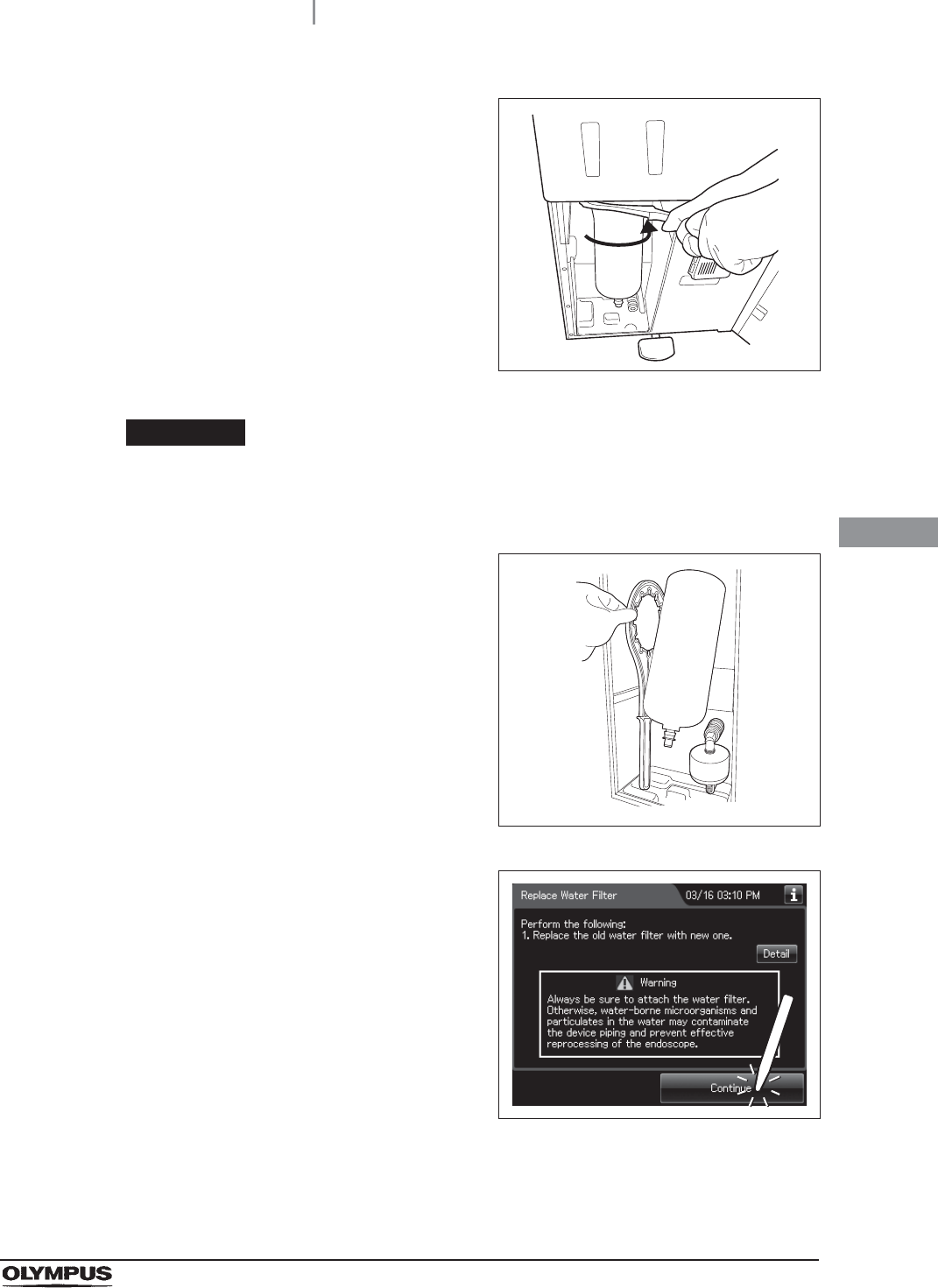
11 Hold the water filter housing with both hands
and rotate it in the direction shown to remove it.
Figure 4.83
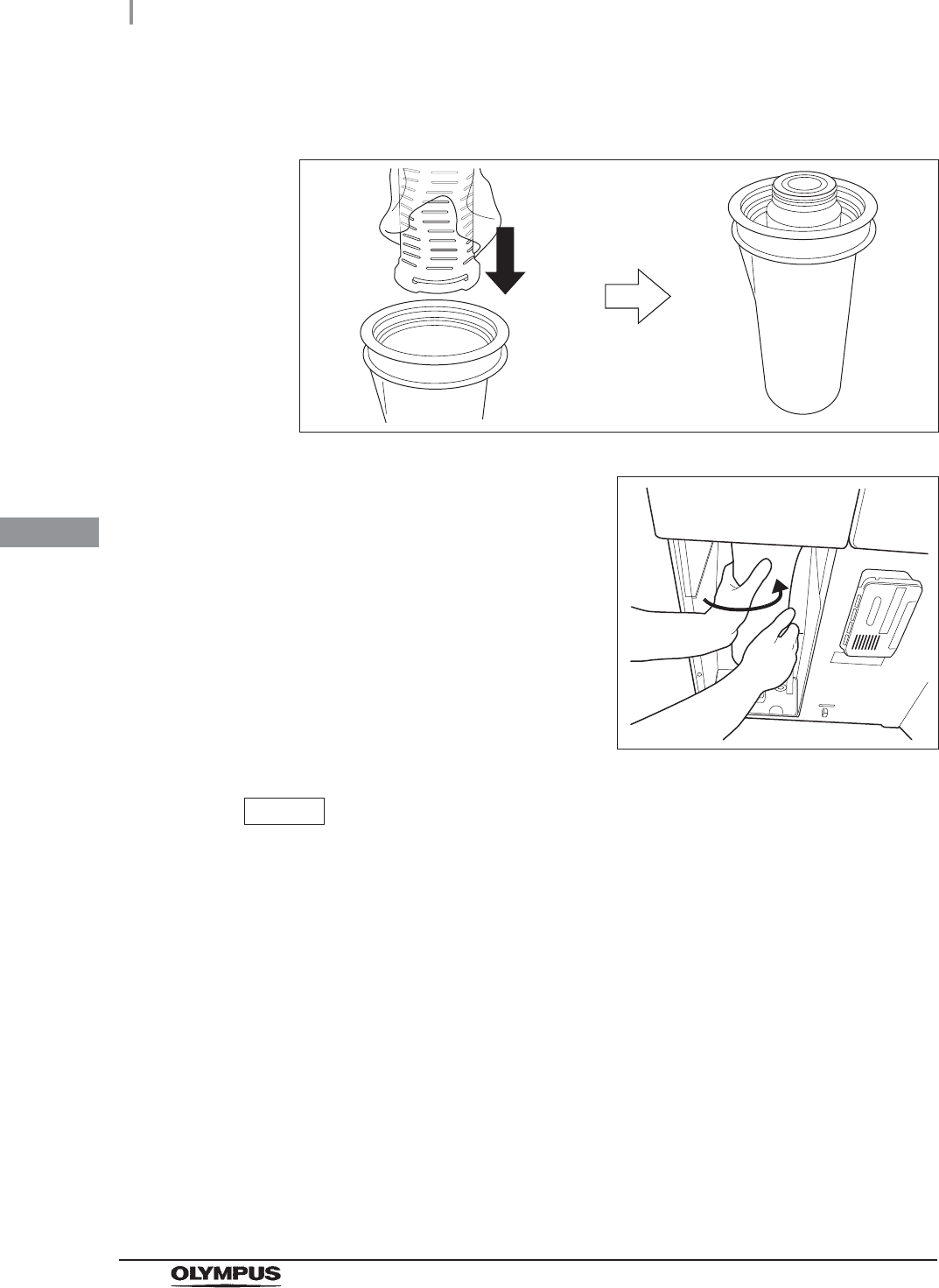
12 Open the bottom (the side without the O-ring) of the package containing the new
water filter.
Projection
106
4.14 Installation of the water filter (MAJ-824 or MAJ-2318)
OER-Elite INSTALLATION MANUAL
Ch.4
13 Hold the water filter housing and place the new water filter directly from the bag into
the water filter housing so that its O-ring will be positioned upward.
Figure 4.84
14 Attach and rotate the water filter housing in the
direction shown to secure it temporarily.
Figure 4.85
NOTE
• To ensure smooth installation, it is recommended to moisten the O-ring at the head
of the water filter with clean water or ethanol before securing it temporarily.
• The rotation drag increases during temporary securing, but rotate the case all the
way until it is stopped.
4.14 Installation of the water filter (MAJ-824 or MAJ-2318)
107
OER-Elite INSTALLATION MANUAL
Ch.4
15 Attach the water filter wrench and rotate it
slowly in the direction shown to tighten.
Figure 4.86
CAUTION
Tighten the water filter case securely. Insecure tightening may lead to a risk of
water leak.
16 Remove the water filter wrench and place it in
the space on the left of the water filter housing.
Figure 4.87
17 Press the “Continue” button.
Figure 4.88
18 Prepare a container with a capacity of at least 2 L and place it in front of the
equipment.
108
4.14 Installation of the water filter (MAJ-824 or MAJ-2318)
OER-Elite INSTALLATION MANUAL
Ch.4
NOTE
If the “Detail Info” button is pressed, the details of work can be displayed on the
touch screen.
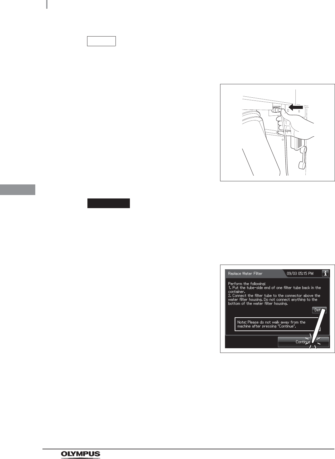
19 Put the tube-side end of the filter tube in the
container, and insert the connector end of the
filter tube into the connector above the water
filter housing until it clicks. Do not connect
anything to the connector below the water filter
housing.
Figure 4.89
CAUTION
Be sure to drain air from the newly attached water filter. If air gets in the water filter
housing, the process time may be extended. Air should also be drained from the
water filter housing whenever there is an irregularity such as extension of the
process time.
20 Press the “Continue” button.
Figure 4.90
4.14 Installation of the water filter (MAJ-824 or MAJ-2318)
109
OER-Elite INSTALLATION MANUAL
Ch.4
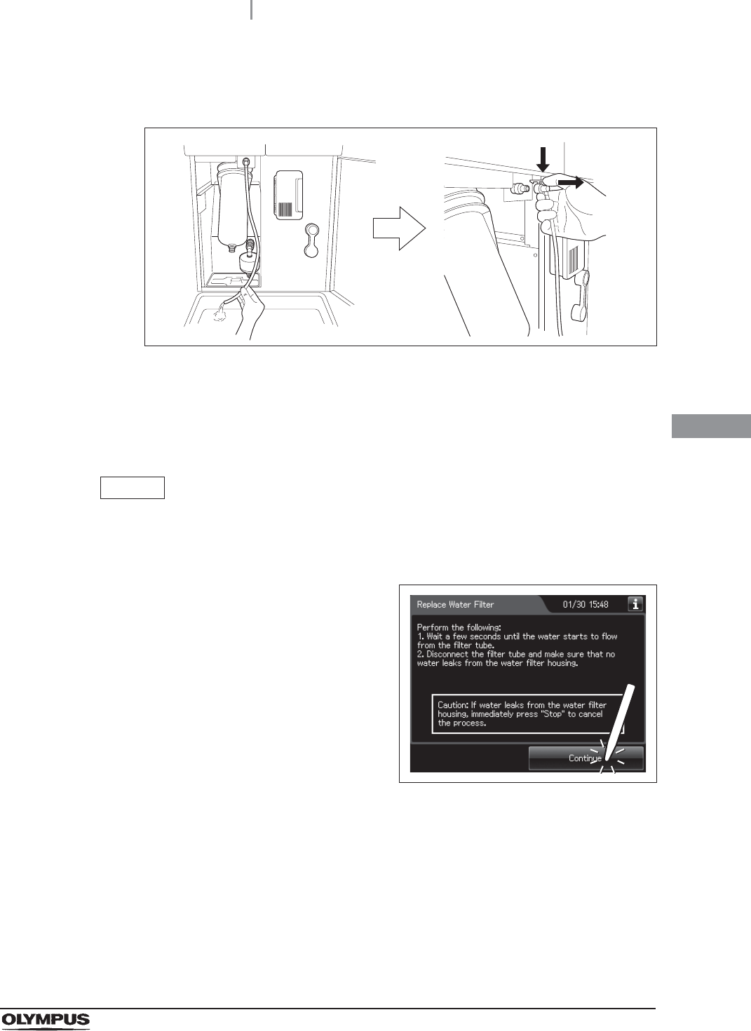
21 When water starts to flow continuously from the filter tube, disconnect the tube by
pushing its lock lever. Water flow should stop when the filter tube is disconnected.
Figure 4.91
22 Check that no water Leaks from the water filter housing. If a Leak is detected,
immediately press the “STOP” button to stop water supply and reinstall the water filter
(perform as described in Section 8.4, “Replacing the water filter (MAJ-824 or
MAJ-2318)” in the “Instructions-Operation Manual”).
NOTE
When the “Stop” button is pressed to stop the process, error code [E000] is
displayed and the auto processing is executed.
23 Press the “Continue” button.
Figure 4.92
110
4.14 Installation of the water filter (MAJ-824 or MAJ-2318)
OER-Elite INSTALLATION MANUAL
Ch.4
24 Press the “OK” button.
Figure 4.93
25 Close the front door.
26 Rinse the filter tube with running water, dry it completely and store in a clean place.

4.14 Installation of the water filter (MAJ-824 or MAJ-2318)
111
OER-Elite INSTALLATION MANUAL
Ch.4
When entering the lot number of the water filter
If the Lot management is activated, enter the Lot number according to the following procedure.
NOTE
The Lot number is printed on a label affixed to the box containing the water filter.
1If the filter lot number management of the water
filter is active, the touch screen displays a
screen as shown in following figure at Step 7 in
“Attachment of the water filter” on page 101.
Press the “Next” button.
Figure 4.94
2Press the “Edit” button to display the lot entry
screen.
Figure 4.95
NOTE
If the “Delete” button is pressed, the entered lot number can be deleted.

112
4.14 Installation of the water filter (MAJ-824 or MAJ-2318)
OER-Elite INSTALLATION MANUAL
Ch.4
3Enter the lot number of the new water filter by the software keyboard on the touch
screen and press the “Save” button.
No. Button Note
1 Alphabet/Numeral
key
Enter the alphabet or a numeral.
2 Uppercase/Lowerc
ase button
Press “Uppercase/lowercase button” to switch alphabet character on the soft keyboard
between uppercases character s and lowercase characters.
3 Numeric/Alphabetic
button
Press “Numeric or Alphabetic button” to switch the input mode between a numeral and
the alphabet.
4 Back space button Press the “Backspace button” to delete the left character of a cursor.
When a cursor is on the leftmost, this button becomes gray and cannot be pressed.
5 Space button Press to the “Space button” to insert a space character.
6 Cursor move button Press to the cursor move button to move a cursor to left or right.
7 Back button Returns to the previous screen without saving the setting value.
8 Save button Returns to the previous screen and save the entered value.
4Press the “Start” button. Go to Step 8 in
“Attachment of the water filter” on page 101.
Figure 4.96
41
2
3
5
6
7 8
41
2
3
5
6
7 8
Alphabet input Numeral input
4.15 Correction of equipment tilt
113
OER-Elite INSTALLATION MANUAL
Ch.4
Make sure that the equipment is not tilted. If it is, correct the tilt as follows.
CAUTION
To prevent fluid leakage, do not use the equipment if it is not level.
NOTE
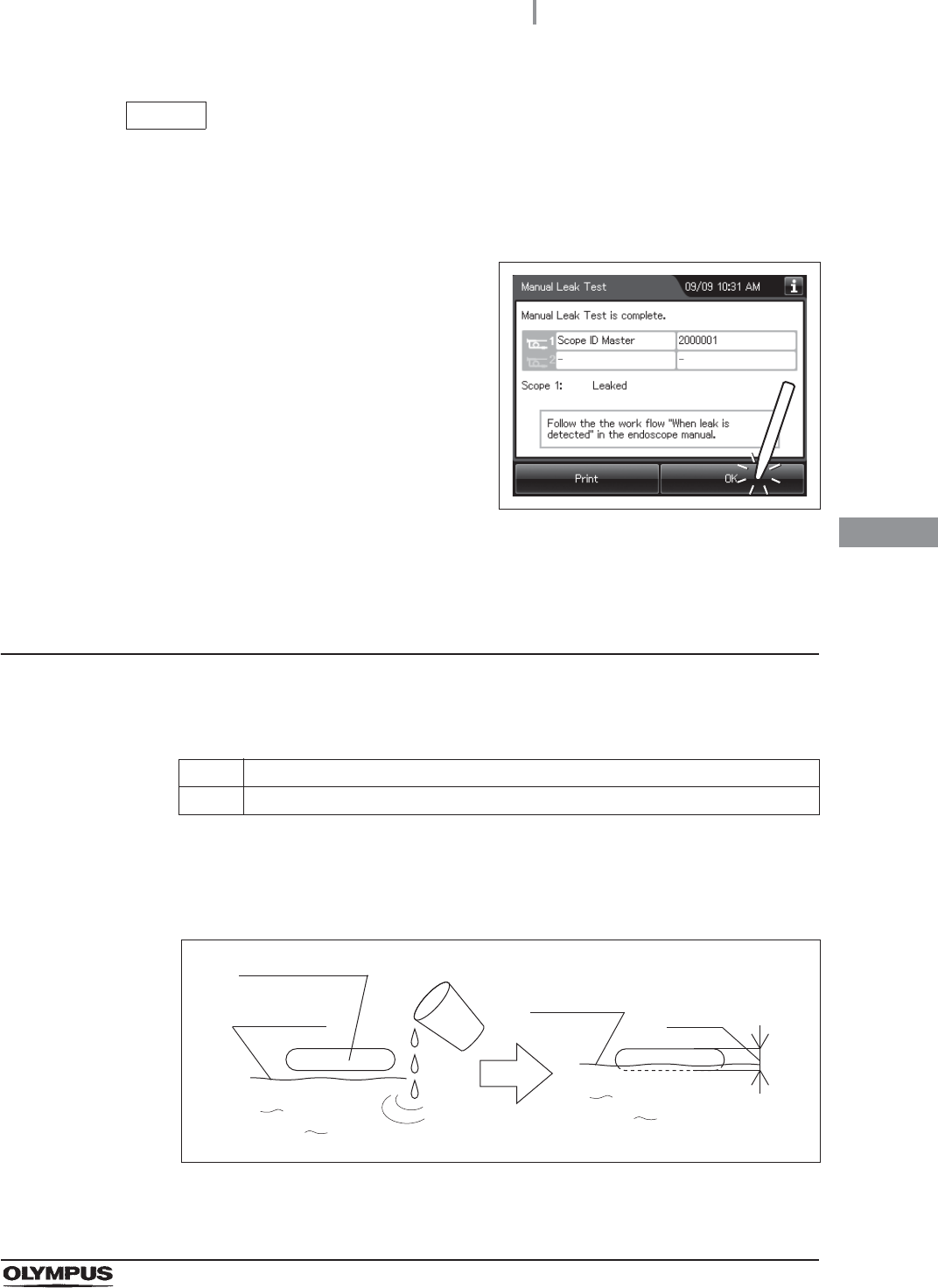
The Manual Leak Test function is performed to supply water to the reprocessing
basin. The work instruction of this section may differ from the instruction displayed
on the touch screen.
4.15 Correction of equipment tilt
1Make sure that the water faucet is open.
2Make sure power is ON.
3Close the lid.
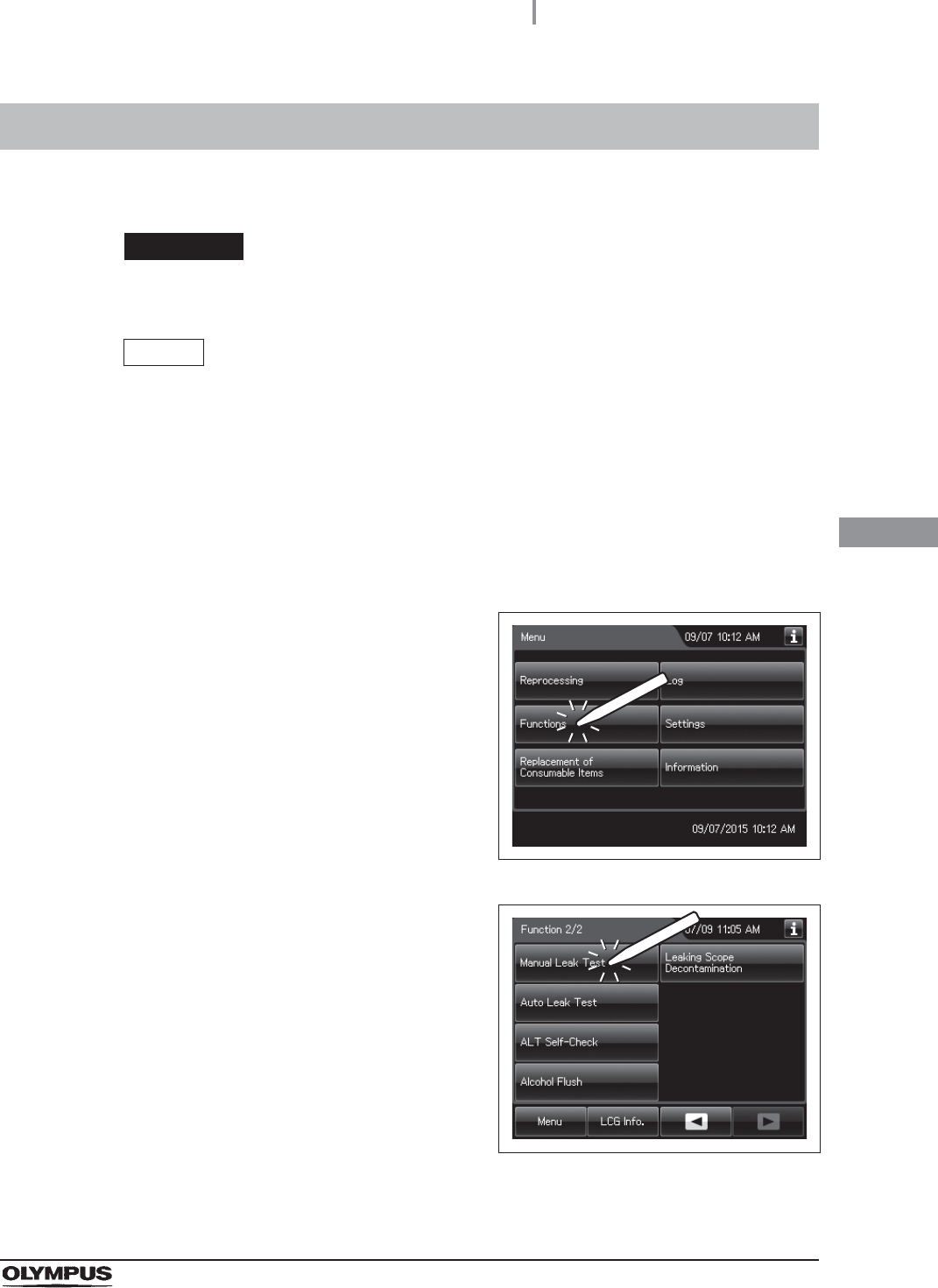
4Press the “Functions” button on the Menu
screen.
Figure 4.97
5Press the “Manual Leak Test” button on the 2nd
page of the functions menu screen.
Figure 4.98
114
4.15 Correction of equipment tilt
OER-Elite INSTALLATION MANUAL
Ch.4
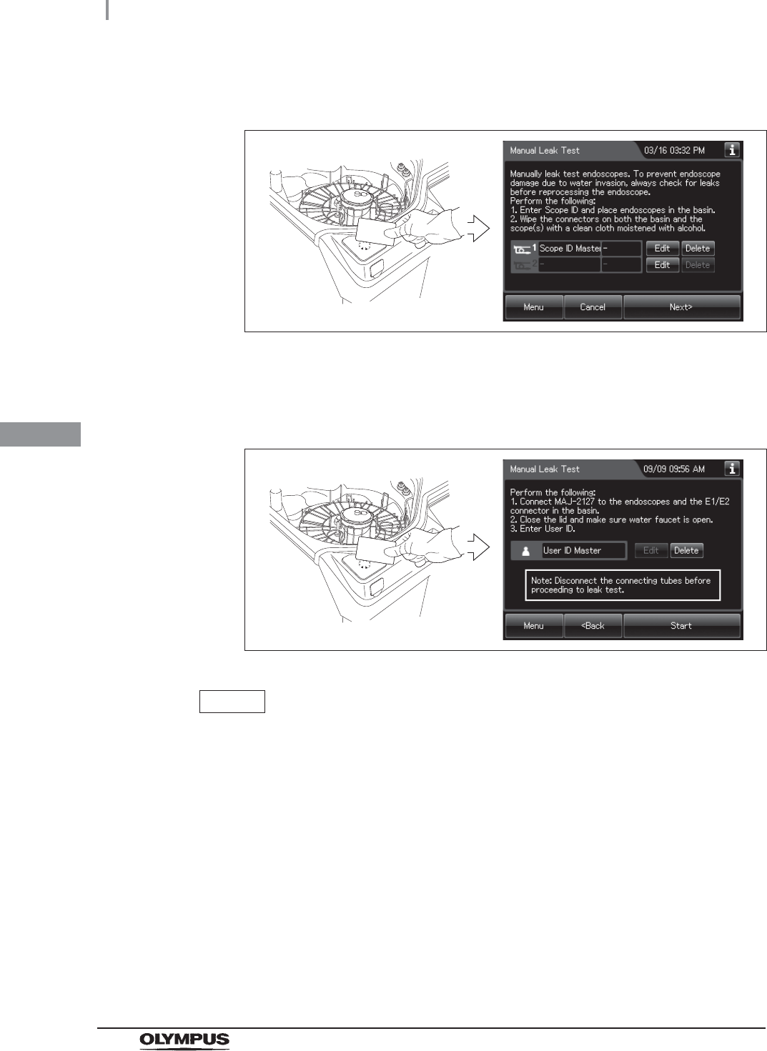
6Hold the scope ID master card parallel to the RFID reader and scan the card with the
reader until the equipment generates a short beep.
Figure 4.99
7Press the “Next” button.
8Hold the User ID master card parallel to the RFID reader and scan the card with the
reader until the equipment generates a short beep.
Figure 4.100
NOTE
• The input of the User ID can be omitted by modifying the User ID input setting. For
details, refer to Section 4.5, “User ID Setting” in “Instructions-Operation Manual”.
• If the “Delete” button is pressed, the entered ID can be deleted.
4.15 Correction of equipment tilt
115
OER-Elite INSTALLATION MANUAL
Ch.4
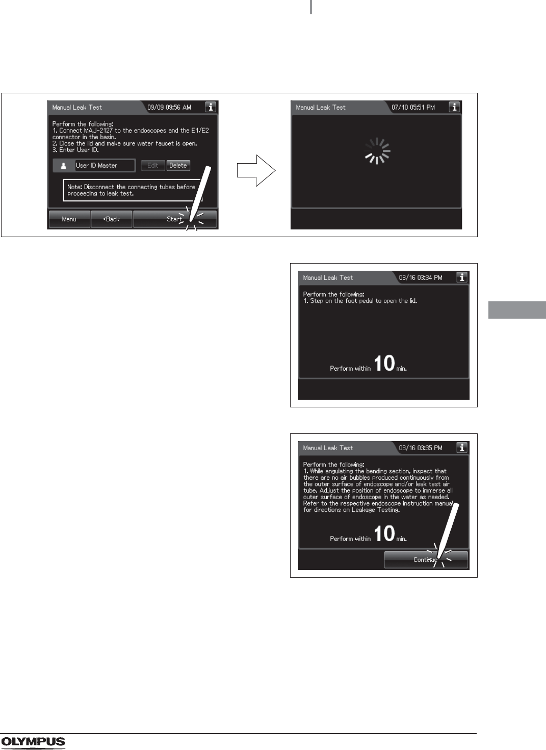
9Press the “Start” button. Water supply to the reprocessing basin starts and the touch
screen changes a screen.
Figure 4.101
10 When the water supply completes, the
equipment generates three buzzer beeps and
unlock the lid. Open the lid within 10 minutes.
Figure 4.102
11 Ensure that the water supply is stopped and
then step on the foot pedal to open the lid.
When the lid is opened, the touch screen
displays the following screen.
Figure 4.103
116
4.15 Correction of equipment tilt
OER-Elite INSTALLATION MANUAL
Ch.4
NOTE
• When the lid is opened, the remaining time displayed on the touch screen is reset
to 10 minutes and the countdown restarts.
• If the lid is not opened within 10 minutes, the fluid in the reprocessing basin is
drained automatically and the manual leak test stops. The touch screen will then
display the error code “E092”.
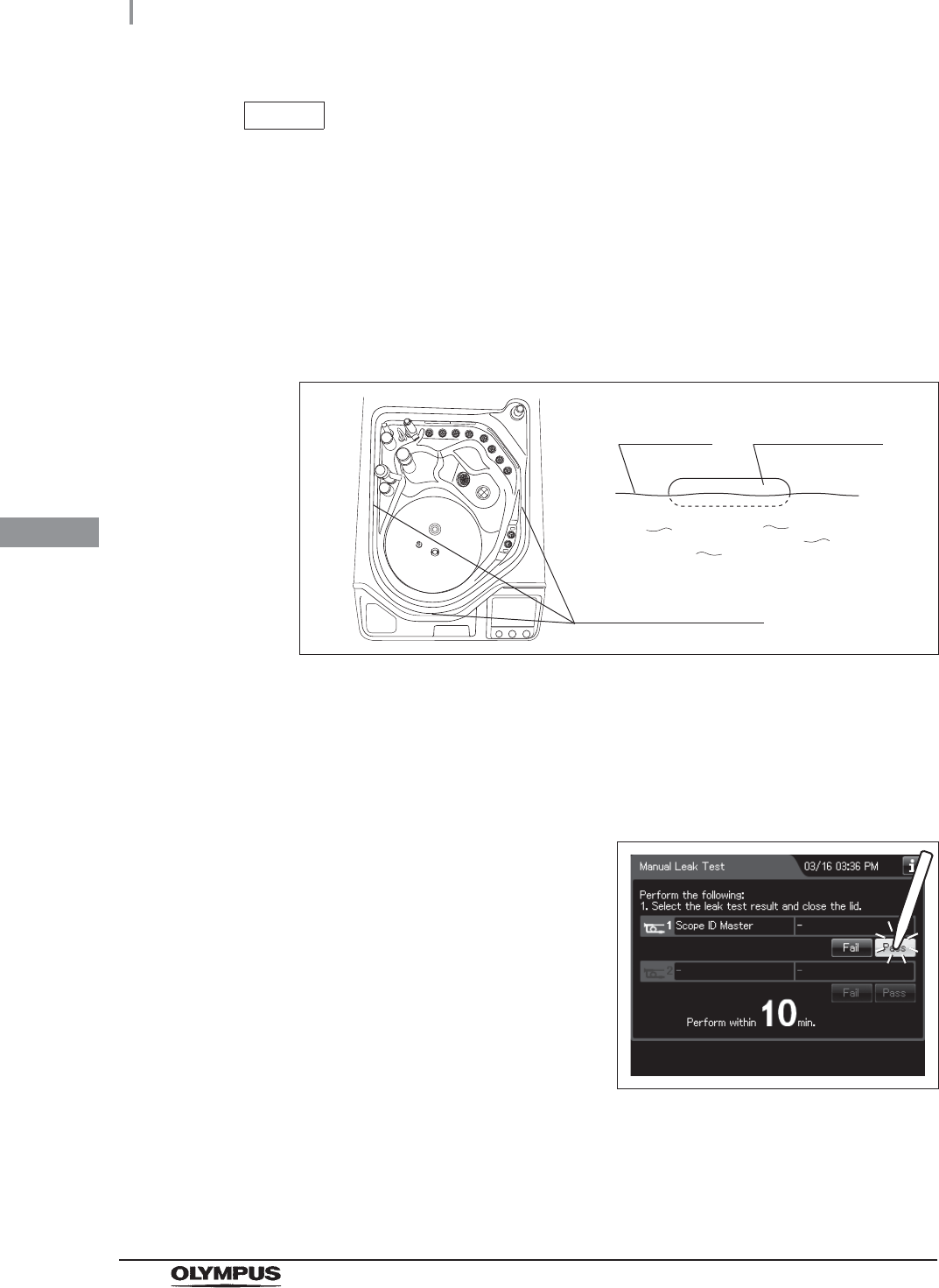
12 Check that the water level is located within the range of each of the three scale
indicators inside the reprocessing basin.
Figure 4.104
13 If the water level is located within all of the ranges of the three scale indicators, it is
not required to correct the equipment tilt.
If the water level is not located within even one of the ranges of the three scale
indicators, adjust according to “Adjustment if water level is not located within even
one of the three ranges” on page 117 and “Correcting the tilt” on page 118.
14 Press the “Pass” button.
Figure 4.105
15 Close the lid. Then the water inside the reprocessing basin is drained.
Scale indicator
Three scale indicators
Water level
4.15 Correction of equipment tilt
117
OER-Elite INSTALLATION MANUAL
Ch.4
Adjustment if water level is not located within even one of
the three ranges
Required items
Table 4 . 4
NOTE
Even if the process is not completed by closing the lid, the water is drained
automatically 10 minutes after the water supply stopped. The touch screen will
then display error code [E092].
16 When draining has completed, the equipment
generates three buzzer beeps and the
touchscreen shows the following screen. Press
the “OK” button to finish.
Figure 4.106
Check Required items
Container such as a cup
1Check the water level. Using a cup, add or remove water until the water level reaches
the scale indicator that had the largest deviation from the water level.
Figure 4.107
Water level
Scale indicator
Water level
Range
118
4.15 Correction of equipment tilt
OER-Elite INSTALLATION MANUAL
Ch.4
Correcting the tilt
The tilt of the equipment can be adjusted by turning the nuts on the four casters. After correcting the
tilt, push the caster lock levers down to stabilize the equipment.
Required items
Table 4.5
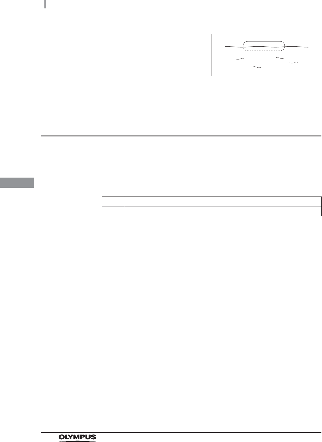
2Also, check the other scale indicators to ensure
that the water level is within their respective
ranges.
Figure 4.108
3If the water level is still out of the range of the other scale indicators, the equipment
may be tilted. Correct the tilt as described in “Correcting the tilt” on page 118 below.
Check Required items
Provided wrench
4.15 Correction of equipment tilt
119
OER-Elite INSTALLATION MANUAL
Ch.4
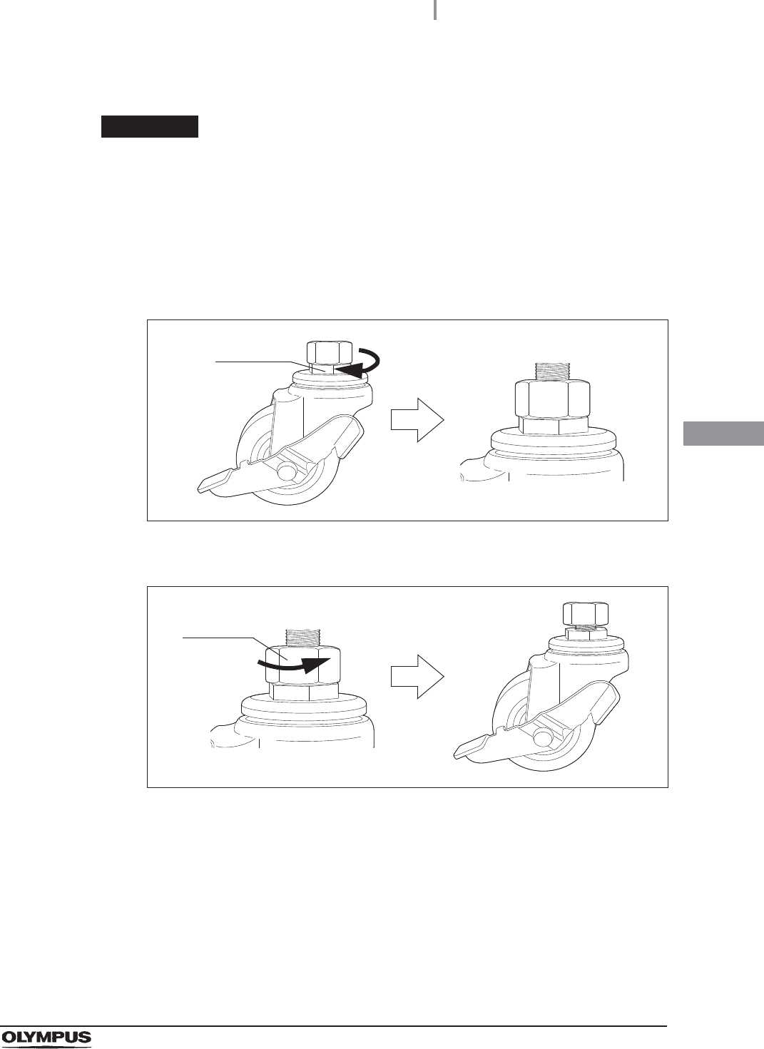
Raising the height
WARNING
The height is set to the lowest position at the factory. Therefore, the height cannot
be reduced below the factory shipped height. The height can be raised by up to
10 mm (0.4 in). If it is raised higher, the casters may separate, causing equipment
damage or injury.
1Using the provided wrench, turn the lower nut on each caster in the direction shown in
Figure 4.109 to set the desired height.
Figure 4.109
2Turn the upper nut on each caster in the direction shown in Figure 4.110 to tighten.
Figure 4.110
Lower nut
Upper nut
120
4.15 Correction of equipment tilt
OER-Elite INSTALLATION MANUAL
Ch.4
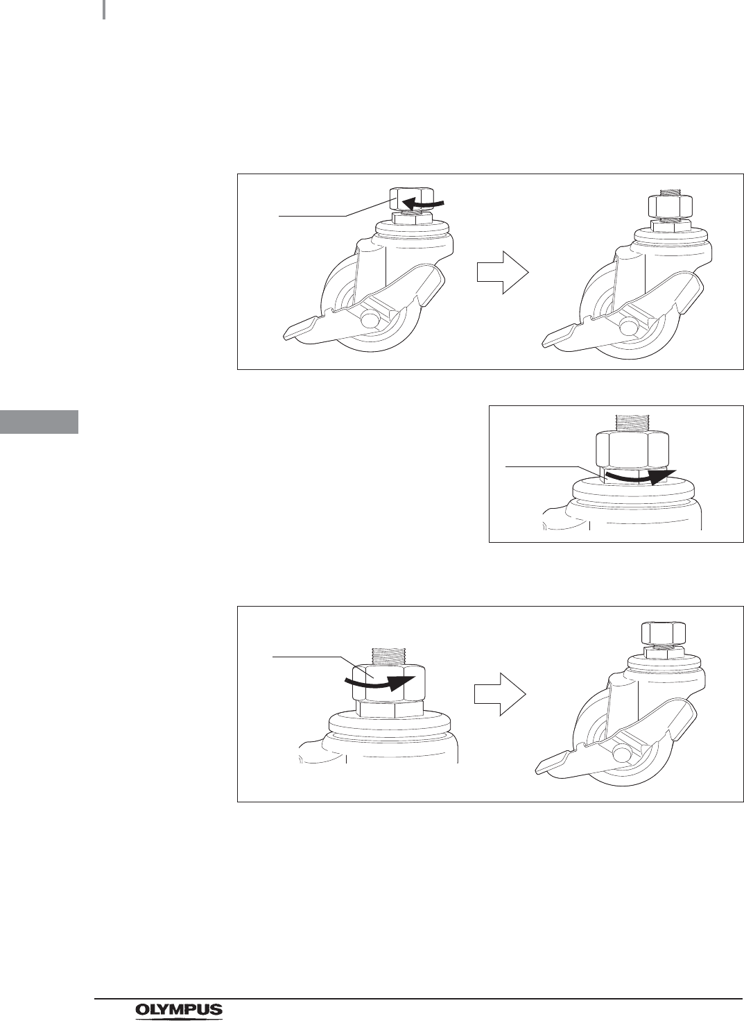
Lowering the height
1Using the provided wrench, turn the upper nut of each caster in the direction shown in
Figure 4.111 to loosen the current height setting.
Figure 4.111
2Turn the lower nut on each caster in the
direction shown in Figure 4.112 to set the
desired height.
Figure 4.112
3Turn the upper nut on each caster in the direction shown Figure 4.113 to tighten.
Figure 4.113
Upper nut
Lower nut
Upper nut
4.16 Inspecting the detergent/alcohol inner tray
121
OER-Elite INSTALLATION MANUAL
Ch.4
The detergent/alcohol inner tray is used to hold the detergent tank and alcohol tank in position so that
they will not fall over.
4.16 Inspecting the detergent/alcohol inner tray
1Hold the section marked “PULL” on the
detergent/alcohol drawer and pull it out.
Figure 4.114
2Check if the detergent/alcohol inner tray is
properly installed as shown in Figure 4.115.
Figure 4.115
Detergent/
alcohol inner
tray
122
4.17 Inspecting the alcohol tank
OER-Elite INSTALLATION MANUAL
Ch.4
The alcohol tank is used to store alcohol for use during alcohol flush.
CAUTION
Do not install the alcohol tank unless the ventilation tube is properly secured to the
side of the alcohol tank.
4.17 Inspecting the alcohol tank
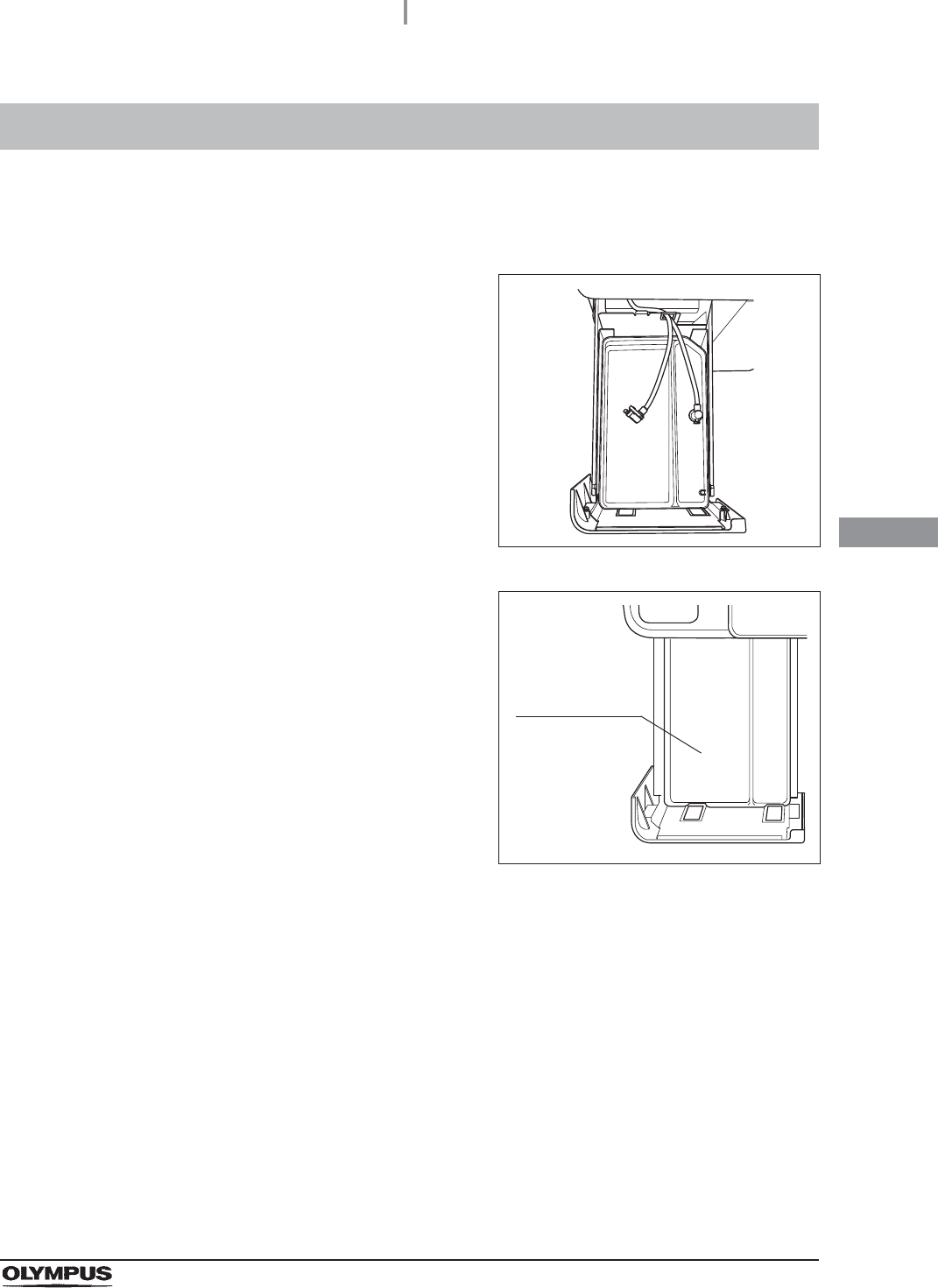
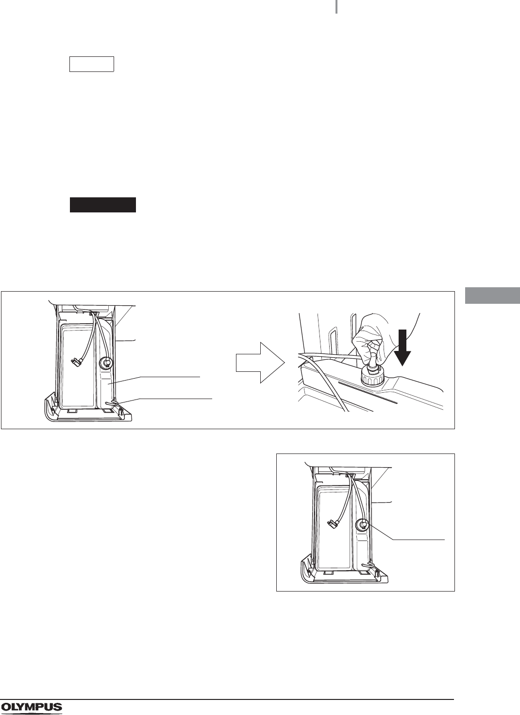
1Place the alcohol tank on the detergent/alcohol drawer so that the ventilation tube sits
on the front of the tray.
2Insert the blue connector into the connector on
the alcohol tank until it clicks.
Figure 4.116
3Rotate the connector and orientate the tube as
shown in Figure 4.117.
Figure 4.117
4Close the detergent/alcohol drawer.
Alcohol tank Ventilation tube
Connector
4.18 Addition of alcohol
123
OER-Elite INSTALLATION MANUAL
Ch.4
WARNING
• The alcohol used with the equipment must be 70% ethyl alcohol or 70% isopropyl
alcohol. Using any other kind of alcohol may result in malfunction of the equipment
or insufficient reprocessing of the endoscope, difficulty drying the endoscope, fire
hazard, or a hazard due to toxic vapor emitted from the alcohol.
• Alcohol is flammable and should be handled with extra care.
• Drain the alcohol in the alcohol tank and replace it with new alcohol at least once a
week. Otherwise, the alcohol in the tank may degrade.
• Before handling alcohol, read the cautions carefully and use as instructed.
NOTE
• If alcohol flush is initiated without alcohol in the tank, the message screen “Alcohol
cannot be supplied” will be displayed and the process will be stopped temporarily.
• When the reprocessing process is performed with newly-installed equipment or
with equipment after Section 9.9, “Preparing the reprocessor for long-term storage”
in “Instructions-Operation Manual” is performed, the reprocessing process may
stop temporarily with the message screen “Alcohol cannot be supplied” displayed
even though there is enough alcohol in the tank.
4.18 Addition of alcohol
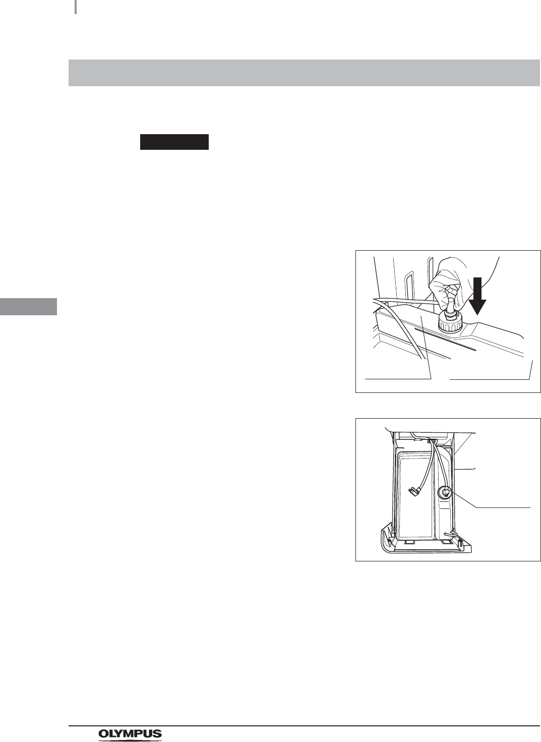
1Hold the section on the detergent/alcohol
drawer marked “PULL” and pull it out.
Figure 4.118
124
4.18 Addition of alcohol
OER-Elite INSTALLATION MANUAL
Ch.4
2Push the lock lever on the connector of the
tube connected to the cap on the alcohol tank
to detach the tube.
Figure 4.119
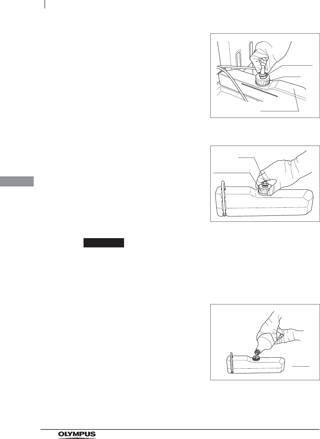
3Remove the alcohol tank and place it in a sink or other tub.
4Turn the cap on the alcohol inlet in the direction
shown in Figure 4.120 to remove it.
Figure 4.120
CAUTION
• Do not add alcohol while the tank is in the detergent/alcohol drawer. If alcohol is
spilled on the plate, it could damage the equipment.
• Do not knock over the alcohol tank while there is still alcohol inside. Otherwise, the
alcohol may spill.
5Carefully pour the 70% ethyl alcohol or 70%
isopropyl alcohol into the alcohol tank until it is
level with the line inside the tank. If any alcohol
is spilled from the tank, wipe it with a clean
cloth. Replace the cap on the alcohol tank,
making sure that it is tight.
Figure 4.121
Cap
Alcohol tank
Lock lever
Cap
Alcohol inlet
Line
4.18 Addition of alcohol
125
OER-Elite INSTALLATION MANUAL
Ch.4
NOTE
When the alcohol tank is filled to the line, it will hold about 1 L (33 ounces) of
alcohol (enough for about 20 alcohol flushes).
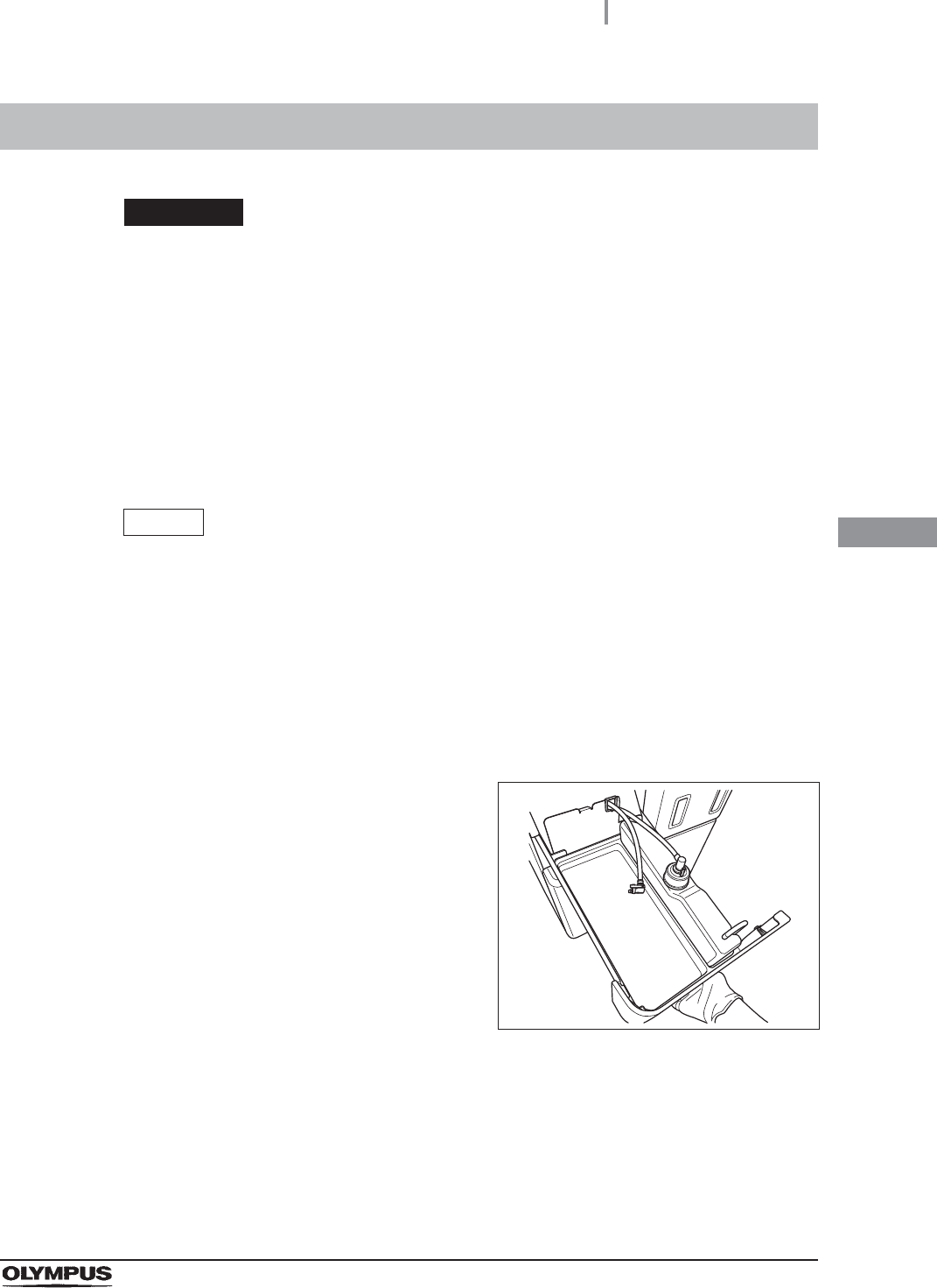
6Place the alcohol tank in the detergent/alcohol drawer so that the ventilation tube of
the alcohol tank sits on the front of the tray. Ensure that the vent tube is properly
attached to the side of the alcohol tank and then place the tank in the detergent
alcohol drawer.
CAUTION
Placing the alcohol tank so that the ventilation tube sits on the deeper side of the
tray could damage the alcohol tank.
7Connect the tube that was originally connected to the cap.
Figure 4.122
8Turn the connector to orientate the tube as
shown in Figure 4.123. Confirm that the tube is
not bent.
Figure 4.123
9Close the detergent/alcohol drawer.
Alcohol tank
Ventilation tube
Connector

126
4.19 Installation of the detergent tank
OER-Elite INSTALLATION MANUAL
Ch.4
Installation of the detergent tank as described below.
When the detergent tank is installed in the following procedure, the record of the detergent tank
replacements can be stored in memory.
WARNING
• Before handling the detergent, read the cautions and instructions for use carefully,
get fully accustomed to the content, and use the detergent as instructed. Make sure
that you fully understand what measures need to be taken if you get any detergent
on your skin.
• Always use an Olympus-validated detergent. Otherwise, the endoscopes may not
be properly cleaned and as a result, the endoscopes may not achieve high-level
disinfection.
• When handling the detergent, always wear appropriate personal protective
equipment, such as eyewear, face mask, moisture-resistant clothing, and
chemical-resistant gloves that fit properly and are long enough so that your skin is
not exposed. All personal protective equipment should be inspected before use
and replaced periodically before it is damaged.
• To prevent the detergent from leaking, do not tilt the detergent tank when there is
detergent inside.
NOTE
• If detergent has run out and the message screen “Detergent cannot be supplied” is
displayed, the equipment will stop the process. Refer to “When the “Message
093” is displayed” on page 159.
• For Olympus-validated detergents, Refer to Section 2.8 “Consumable accessories
(Optional)”.
• The detergent tank can hold about 2.8 L (95 ounces) of detergent (which can be
used for approximately 30 reprocessing operations).
• When the reprocessing process is performed with newly-installed equipment or
with equipment after Section 9.9, “Preparing the reprocessor for long-term storage”
in “Instructions-Operation Manual” is performed, the reprocessing process may
stop temporarily with the message screen “Detergent cannot be supplied”
displayed even though there is enough detergent in the tank.
• The shelf-life and/or lot number of the detergent can be recorded in the detergent
replacement history. For changing the shelf-life and lot management of the
detergent, refer to Section 4.11, “Detergent lot number and shelf-life management”
in “Instructions-Operation Manual”.
4.19 Installation of the detergent tank
4.19 Installation of the detergent tank
127
OER-Elite INSTALLATION MANUAL
Ch.4
Required items
Table 4 . 6
Installing the detergent tank
Check Required items
Olympus-validated detergent
1Close the lid.
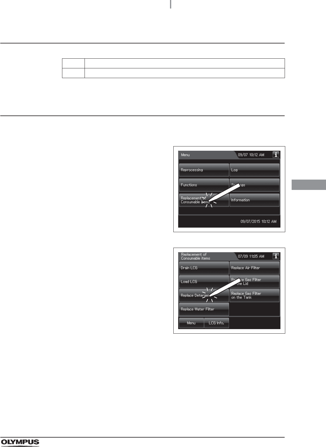
2Press the “Replacement of Consumable Items”
button on the Menu screen.
Figure 4.124
3Press the “Replace Detergent” on the
Replacement of Consumable Items menu.
Figure 4.125
128
4.19 Installation of the detergent tank
OER-Elite INSTALLATION MANUAL
Ch.4
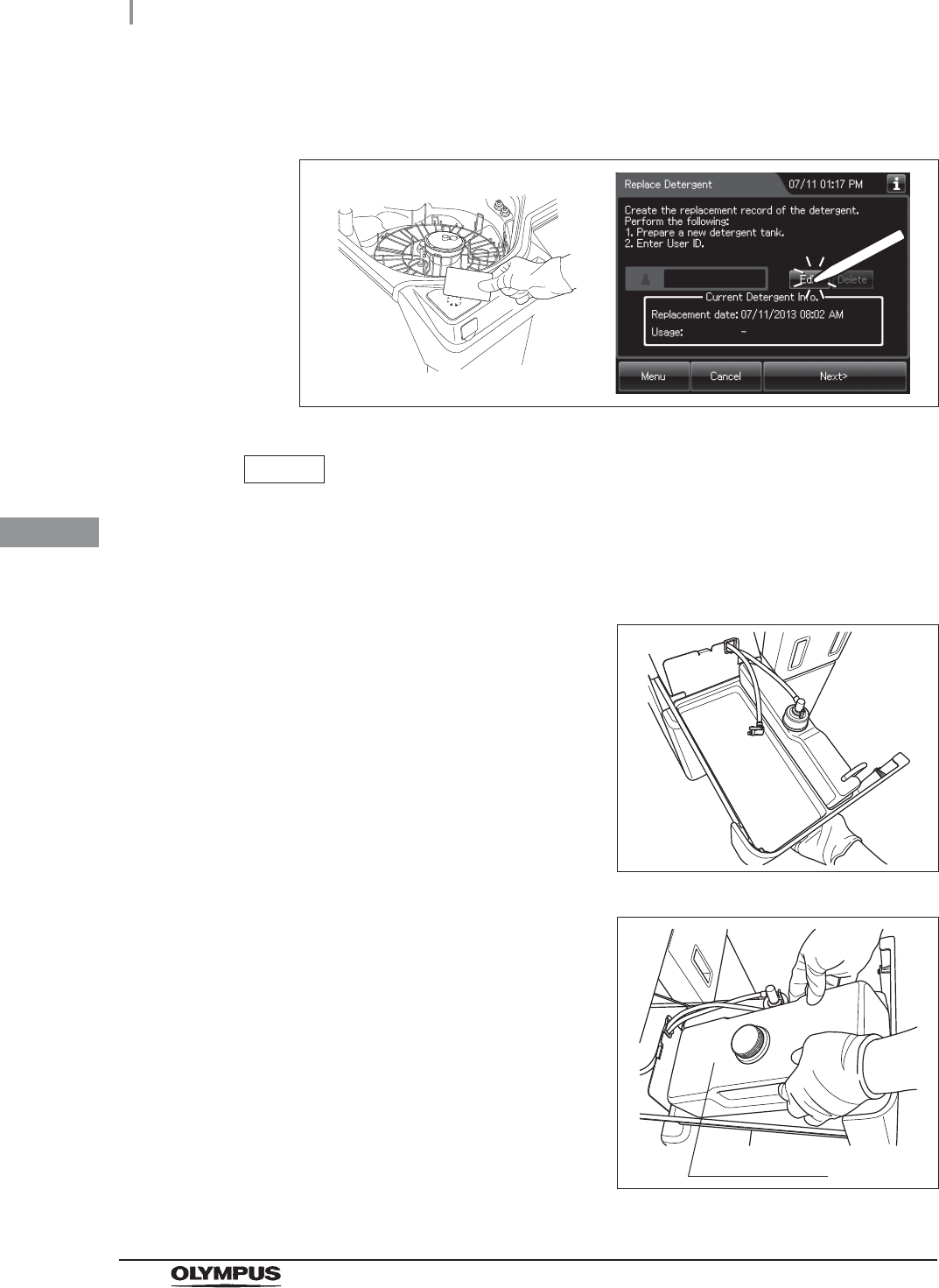
4Enter the operator's user ID. For the detailed procedures, refer to Section 3.6,
“Entering ID” in “Instructions-Operation Manual” (If applicable).
Figure 4.126
NOTE
• The input of the user ID can be omitted by modifying the user ID input setting. For
details, refer to Section 4.5, “User ID Setting” in “Instructions-Operation Manual”.
• If the “Delete” button is pressed, the entered ID can be deleted.
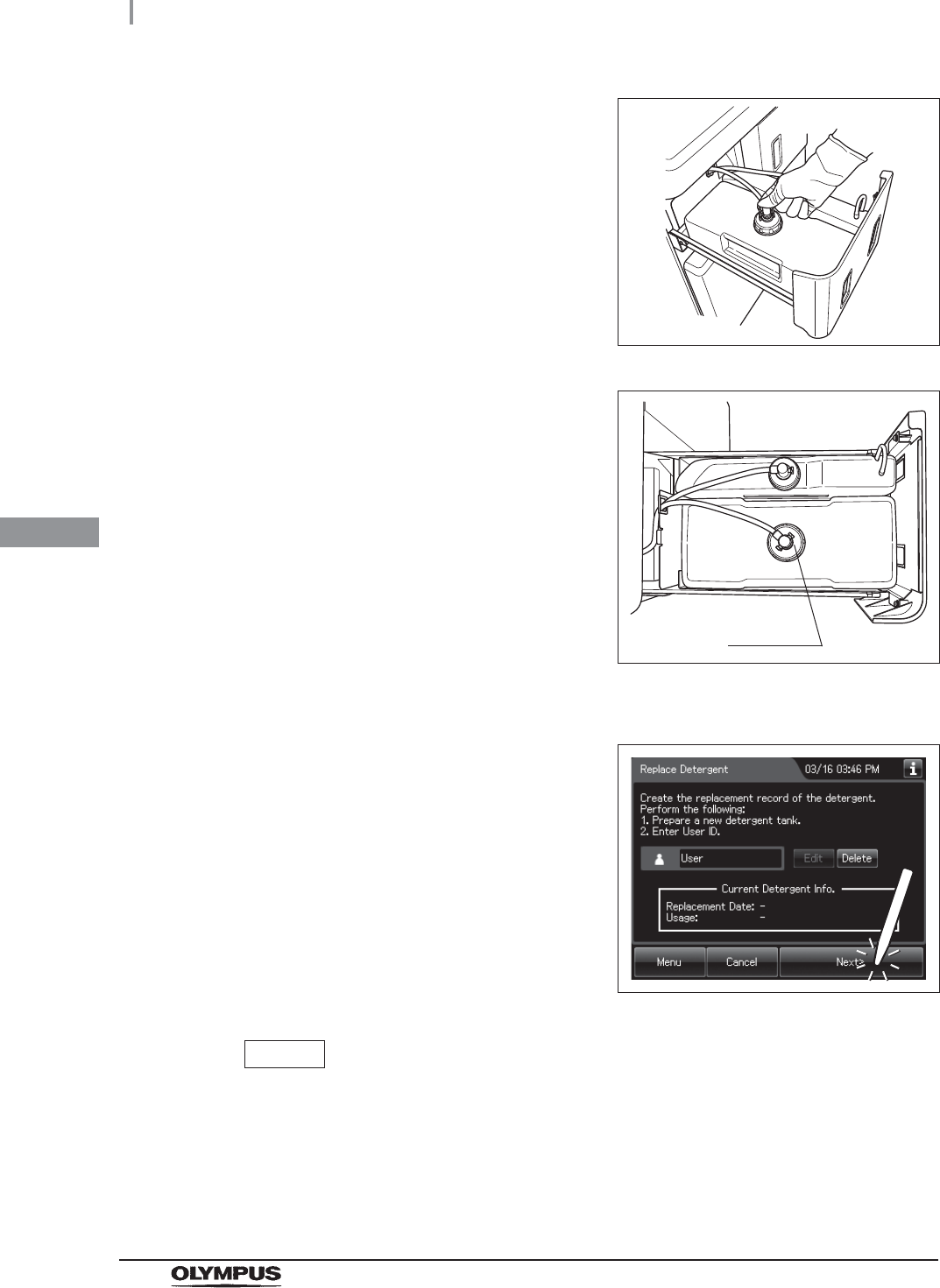
5Hold the section marked “PULL” on the
detergent/alcohol drawer and pull it out.
Figure 4.127
6Place the new detergent tank on the left side of
the detergent/alcohol drawer.
Figure 4.128
Detergent tank
4.19 Installation of the detergent tank
129
OER-Elite INSTALLATION MANUAL
Ch.4
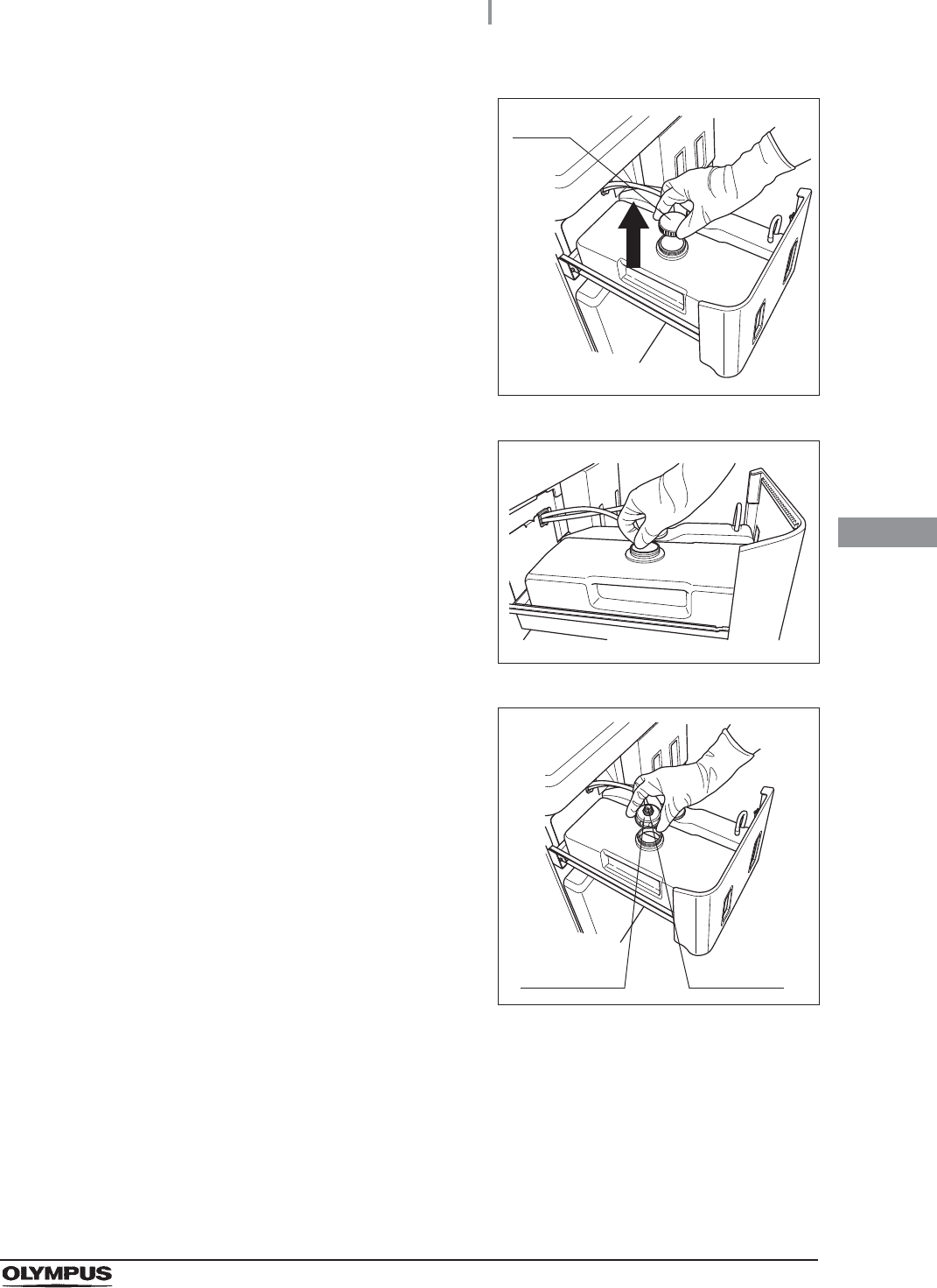
7Remove the detergent tank cap.
Figure 4.129
8Remove the seal on the detergent tank.
Figure 4.130
9Attach the cap with connector to the detergent
tank.
Figure 4.131
Cap
Attachment Connector
130
4.19 Installation of the detergent tank
OER-Elite INSTALLATION MANUAL
Ch.4
10 Insert the gray connector into the connector on
the detergent tank until it clicks.
Figure 4.132
11 Turn the connector to correct the tube
orientation as show in Figure 4.133. Confirm
that the tube is not bent.
Figure 4.133
12 Close the detergent/alcohol drawer.
13 Press the “Next” button.
Figure 4.134
NOTE
If the shelf-life and lot management of the detergent are activated, the shelf-life or
lot number of detergent can be entered after Step 13. For entering the shelf-life
and/or lot number of the detergent, refer to “When entering the shelf-life and/or
lot number of the disinfectant solution:” on page 142.
Connector
4.19 Installation of the detergent tank
131
OER-Elite INSTALLATION MANUAL
Ch.4
When entering the lot number of detergent and shelf life:
If the lot number of detergent and Shelf life management is activated, enter the lot number
and/or shelf life according to the following procedure.
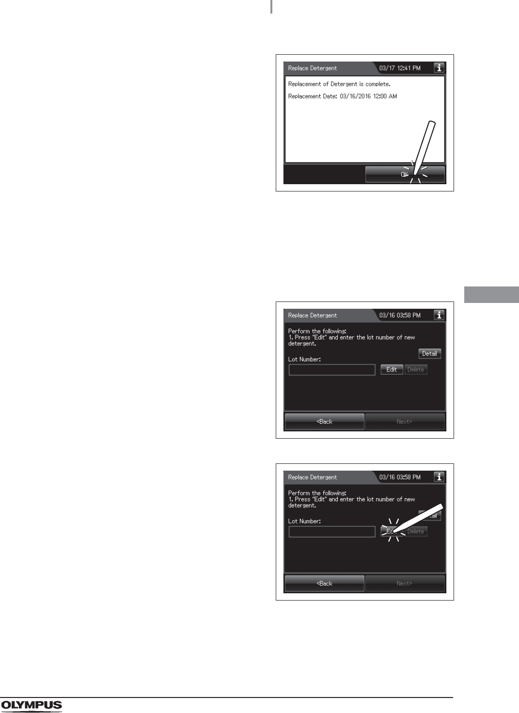
14 Press the “OK” button.
Figure 4.135
1If the lot number management of the detergent
is activated, the touch screen displays the
screen as shown in following figure after Step
13 in “Installing the detergent tank” on
page 127. If the lot number management of the
detergent is inactivated, go to Step 5.
Figure 4.136
2Press the “Edit” button to display the lot number
entry screen.
Figure 4.137
132
4.19 Installation of the detergent tank
OER-Elite INSTALLATION MANUAL
Ch.4
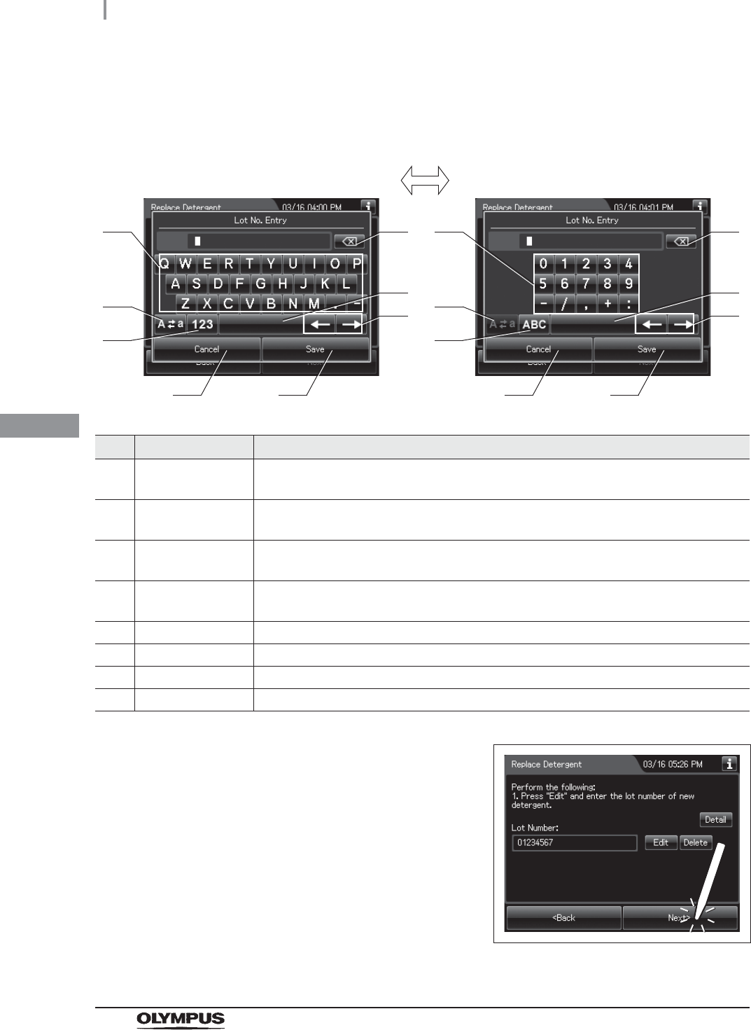
3Enter the lot number of the new detergent by the software keyboard on the touch
screen and press the “Save” button.
No. Button Note
1 Alphabet/
Numeral key
Enter the alphabet or a numeral.
2 Uppercase/
Lowercase button
Press the “Uppercase/Lowercase” button to switch alphabet character on the soft
keyboard between uppercase characters and lowercase characters.
3 Numeric/
Alphabetic button
Press the “Numeric/Alphabetic” button to switch the input mode between a numeral and
the alphabet.
4 Backspace button Press the “Backspace” button to delete the left character of a cursor.
When a cursor is on the left edge, this button becomes gray and unavailable.
5 Space button Press the “Space” button to insert a space character.
6 Cursor move button Press the “Cursor move” button to move a cursor to left or right.
7 Cancel button Return to the previous screen without saving the setting value.
8 Save button Return to the previous screen and save the entered value.
4Press the “Next” button. If the shelf-life
management of the detergent is activated, go
to Step 5. If the shelf-life management of the
detergent is inactivated, go to Step 6.
Figure 4.138
41
2
3
5
6
7 8
41
2
3
5
6
7 8
Alphabet input Numeral input
4.19 Installation of the detergent tank
133
OER-Elite INSTALLATION MANUAL
Ch.4
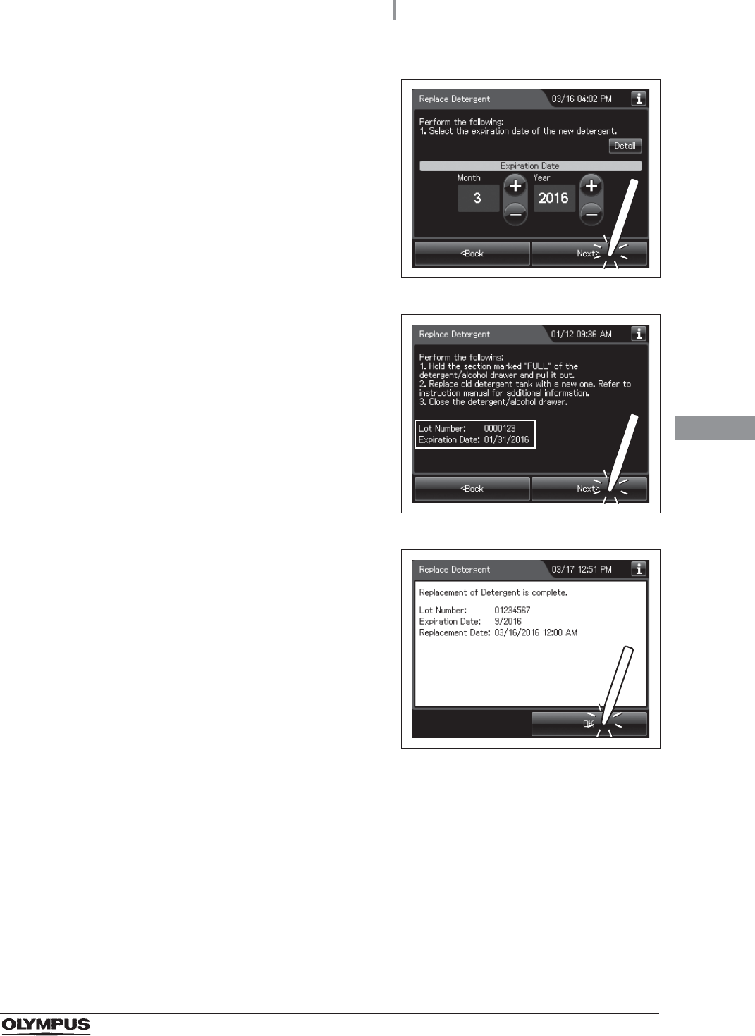
5Enter the Expiration Date of the detergent.
Press the “Plus” button to increase or the
“Minus” button to decrease. Then press the
“Next” button.
Figure 4.139
6Check the displayed lot number and the
expiration date, and press the “Next” button.
Figure 4.140
7Press the “OK” button.
Figure 4.141

134
4.20 Setup of the disinfectant solution
OER-Elite INSTALLATION MANUAL
Ch.4
WARNING
• Before handling the disinfectant solution, read the cautions carefully and use it as
instructed. It is especially important to know what to do if the disinfectant solution
comes in contact with your skin.
• Always use disinfectant that has been validated by Olympus. High-level
disinfectants that are not validated by Olympus for use in the OER-Elite may be
unsafe and ineffective due to improper dilution, incorrect contact time and
temperature, excessive foaming, inadequate rinse, and therefore may compromise
patient safety. Use of a high-level disinfectant that has not been validated by
Olympus may also damage internal OER-Elite components (e.g., seals, valves,
etc.) and the endoscopes being reprocessed.
• When handling the disinfectant solution, wear personal protective equipment to
prevent any disinfectant from getting on your skin or being inhaled. Avoid direct
physical contact and inhalation of vapors. If any disinfectant solution gets in your
eyes, immediately rinse with a large amount of fresh water and then consult a
medical specialist. Wear personal protective equipment, such as eyewear, face
mask, moisture-resistant clothing, and chemical-resistant gloves that fit properly
and are long enough so that your skin is not exposed. All personal protective
equipment should be inspected before use and replaced periodically before it is
damaged.
4.20 Setup of the disinfectant solution

4.20 Setup of the disinfectant solution
135
OER-Elite INSTALLATION MANUAL
Ch.4
WARNING
• When using the disinfectant solution and alcohol, Olympus recommends the use of
gas filters and running this equipment in well-ventilated areas.
Wear a face mask, gloves, and protective clothes to minimize aspiration and
skin contact.
Wear goggles for eye protection.
Refer to the following association’s guidelines related to ventilation:
If the person performing the inspection or maintenance exhibits an allergic reaction
or symptoms no matter how slight they should discontinue the task and vacate the
room.
• Effective reprocessing cannot be guaranteed when a non-validated disinfectant
solution is used. Equipment malfunction may also result.
• Follow the disinfectant manufacturer’s instructions for any preparation or activation
required prior to loading into the OER-Elite.
• If the disinfectant solution in the cassette bottles has not completely drained after
preparation of disinfectant solution, do not use the equipment and contact
Olympus. Inappropriate preparation of disinfectant solution will prevent proper
endoscope reprocessing.
• Do not touch inside the caps of cassette bottles. Do not push or apply strong
pressure to the bottle. Otherwise, disinfectant solution may leak from the bottle.
CAUTION
• To avoid malfunction, do not attempt to pull out the disinfectant bottle drawer while
it is locked.
• Do not put your hand into the disinfectant bottle drawer or near the cassette bottle
cutters. Irritation of skin due to contact with concentrated disinfectant solution,
injury by touching a projection, or malfunction of this equipment may result.
SGNA (Society of Gastroenterology Nurses and Associates)
ASGE (American Society of Gastroenterological Endoscopy)
APIC (Association for Professionals of Infection Control and Epidemiology)
AORN (Association of Preoperative Registered Nurses)
ASTM (American Society for Testing and Materials)
OSHA (Occupational Safety and Health Administration)
ACGIH (American Conference of Governmental Industrial Hygienists)
NIOSH (National Institute for Occupational Safety and Health)
AIA (American Institute of Architects)
136
4.20 Setup of the disinfectant solution
OER-Elite INSTALLATION MANUAL
Ch.4
Required items
Table 4.7
NOTE
For Acecide-C high level disinfectant solution, refer to Section 2.8, “Consumable
accessories (Optional)”.
Setup of the disinfectant solution
CAUTION
• To avoid malfunction, do not attempt to pull out the disinfectant bottle drawer while
it is locked.
• Do not put your hand into the disinfectant bottle drawer or near the cassette bottle
cutters. Irritation of skin due to contact with concentrated disinfectant solution,
injury by touching a projection, or malfunction of this equipment may result.
NOTE
For Acecide-C high level disinfectant solution, refer to Section 2.8, “Consumable
accessories (Optional)”.
Check Required items
Acecide-C high level disinfectant solution
1Make sure that the water faucet is open.
2Close the lid.
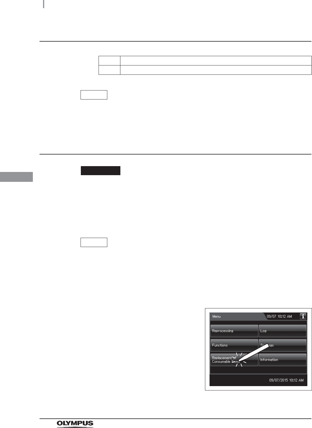
3Press the “Replacement of Consumable Items”
button on the Menu screen.
Figure 4.142
4.20 Setup of the disinfectant solution
137
OER-Elite INSTALLATION MANUAL
Ch.4
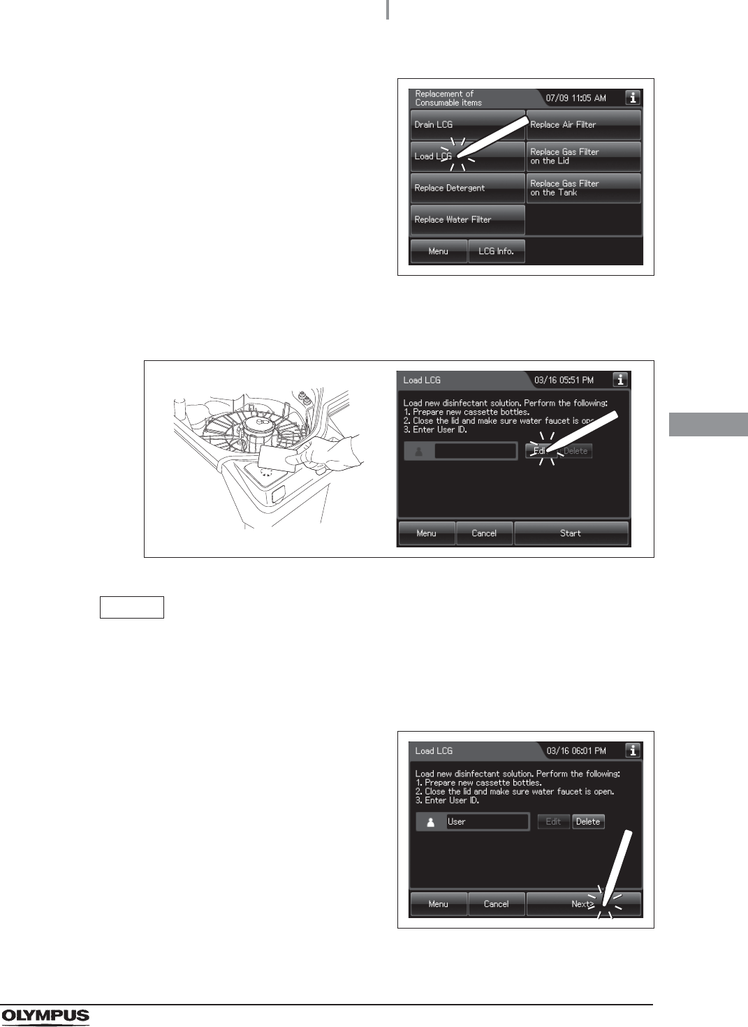
4Press the “Load LCG” button.
Figure 4.143
5Enter the operator's user ID. For the detailed procedures, refer to Section 3.6,
“Entering ID” in “Instructions-Operation Manual” (If applicable).
Figure 4.144
NOTE
• The input of the user ID can be omitted by modifying the user ID input setting. For
details, refer to Section 4.5, “User ID Setting” in “Instructions-Operation Manual”.
• If the “Delete” button is pressed, the entered ID can be deleted.
6Press the “Start” button to unlock the
disinfectant bottle drawer.
Figure 4.145
138
4.20 Setup of the disinfectant solution
OER-Elite INSTALLATION MANUAL
Ch.4
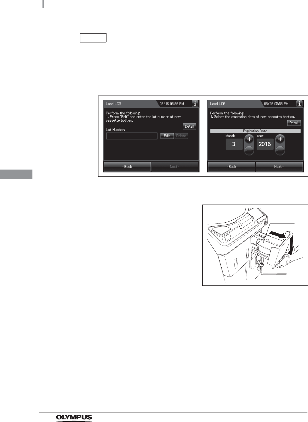
NOTE
• The Load LCG cannot be started unless the disinfectant solution tank is empty.
• If the shelf-life and/or lot management of the disinfectant solution are activated, the
touch screen displays a screen as shown in following figure. For entering the
shelf-life and/or lot number of the disinfectant solution, refer to “When entering
the shelf-life and/or lot number of the disinfectant solution:” on page 142.
Figure 4.146
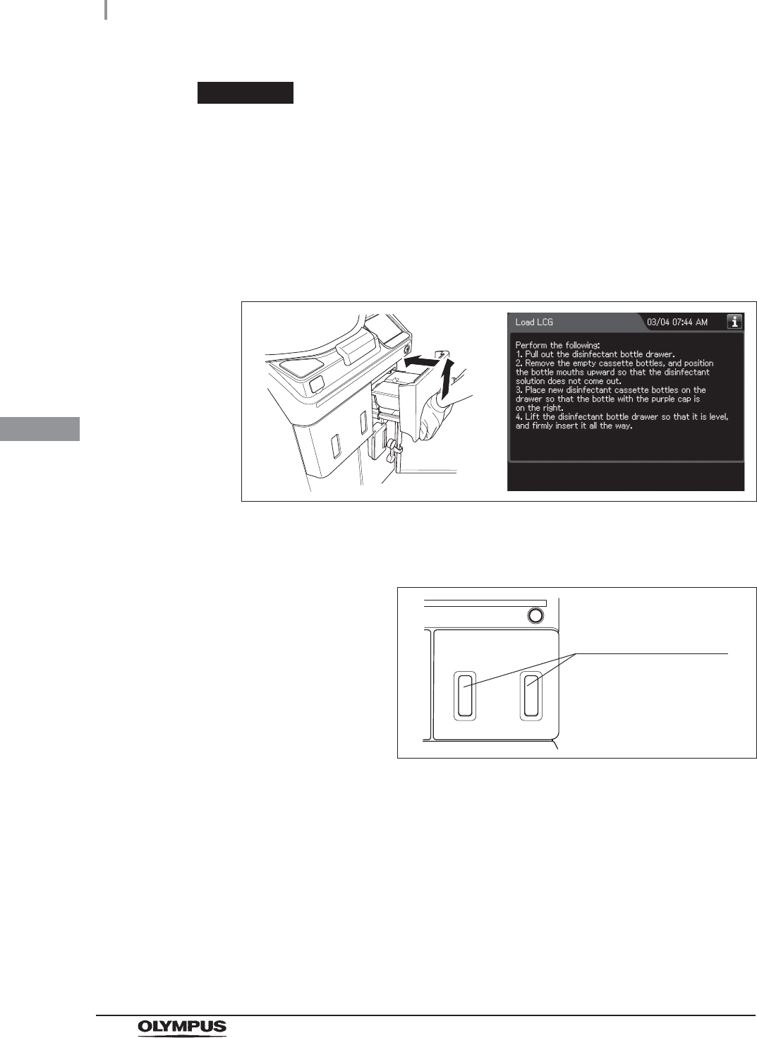
7Pull out the disinfectant bottle drawer.
Figure 4.147
8To remove the empty cassette bottles from the disinfectant bottle drawer, position the
bottle mouths upward so that residual disinfectant solution that might remain in the
bottles does not come out.
9If any disinfectant solution spills, wipe it away with a clean cloth. If the disinfectant
bottle drawer is dirty, clean using a clean cloth moistened with neutral detergent
solution and then wipe with a clean cloth.
Cassette
bottles
4.20 Setup of the disinfectant solution
139
OER-Elite INSTALLATION MANUAL
Ch.4
WARNING
• Do not put your hand behind the disinfectant bottle drawer. Irritation of skin due to
contact with concentrated disinfectant solution, injury by touching a projection, or
malfunction of this equipment may result.
• If the cassette cutters are abnormal, do not use the equipment and contact
Olympus. If the cassette cutters are abnormal, the disinfectant solution cannot be
properly prepared. This will prevent effective endoscope reprocessing and may
cause the equipment to malfunction.
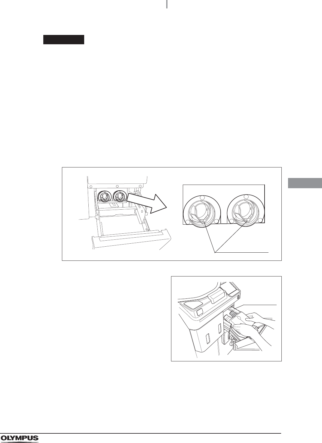
10 Check the two cassette cutters (blades for ripping caps on disinfectant cassette
bottles) placed at the back of the disinfectant bottle drawer. Compare the two blades
and make sure that neither cutter is bent, cracked, or deformed. Changes in color are
not a malfunction.
Figure 4.148
11 Hold the new disinfectant cassette bottles
together and place them on the disinfectant
bottle drawer so that the bottle with the purple
cap is on the right.
Figure 4.149
Cassette cutters
Purple cap
140
4.20 Setup of the disinfectant solution
OER-Elite INSTALLATION MANUAL
Ch.4
CAUTION
When pushing in the disinfectant bottle drawer, hold the disinfectant drawer
horizontally and push it all the way in. Otherwise, the disinfectant cassette bottle
would be unable to be opened and the disinfectant solution would be unable to be
prepared normally.
12 Lift the disinfectant bottle drawer slightly up, and insert it all the way. The buzzer
should beep, the drawer should lock, and the disinfectant cassette bottles should
open automatically.
Figure 4.150
13 Look at the disinfectant bottle drawer and check the windows to verify that the
disinfectant solution in both bottles has decreased.
Figure 4.151
Disinfectant bottle
drawer check windows
4.20 Setup of the disinfectant solution
141
OER-Elite INSTALLATION MANUAL
Ch.4
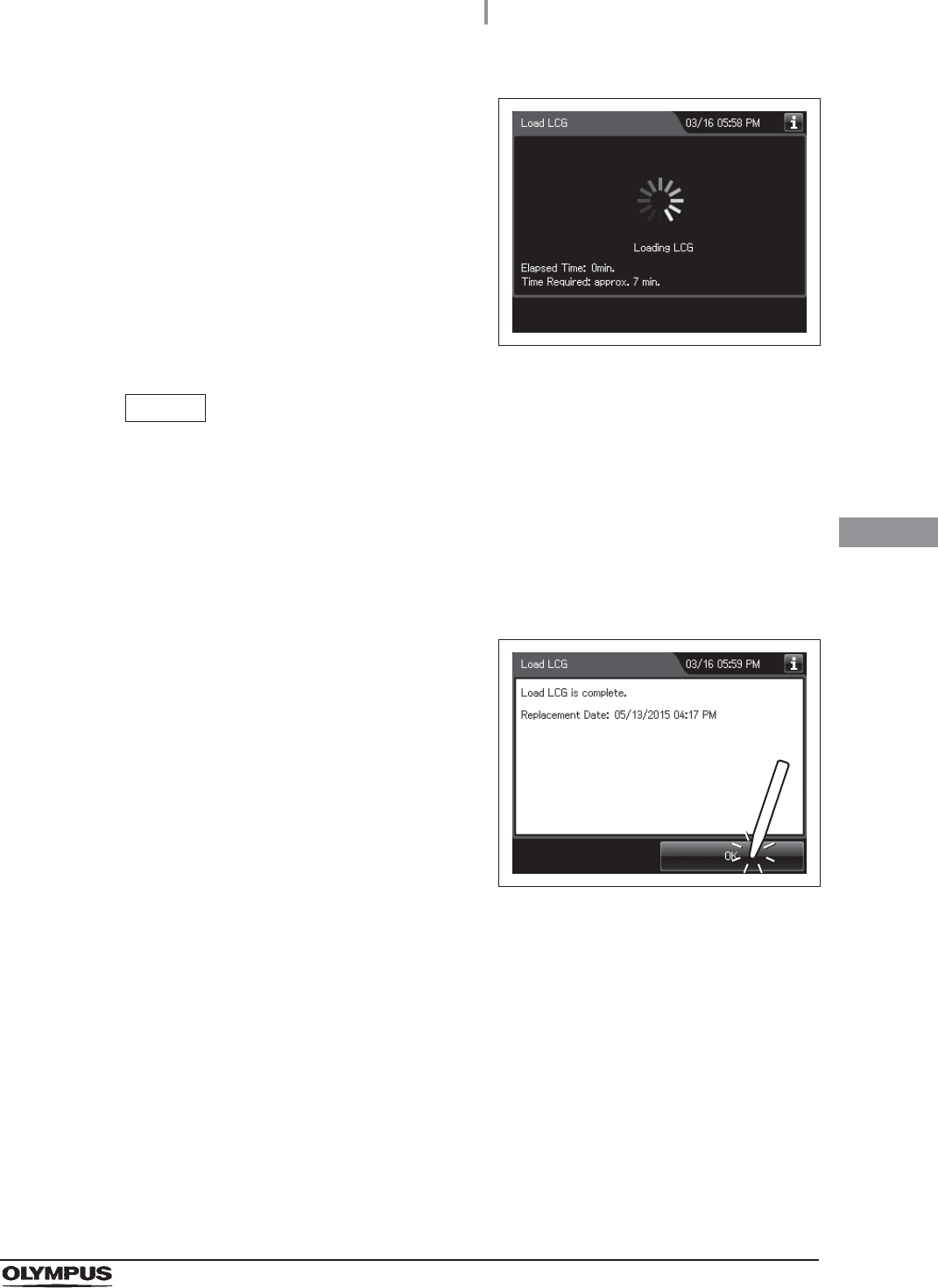
14 The buzzer generates short beeps and the
touch screen displays a screen indicating that
the disinfectant solution is being prepared.
Figure 4.152
NOTE
• Preparation of disinfectant solution includes single rinse process to rinse the
reprocessing basin. While executing the preparation of disinfectant solution,
buzzer beeps intermittently and the main control panel displays as shown in
Figure 4.152. STOP button is deactivated during the process.
• The required time for setup of disinfectant solution may vary depending on the
water supply condition.
15 The touch screen displays the following screen.
This screen indicates the process is completed.
Press the “OK” button.
Figure 4.153
142
4.20 Setup of the disinfectant solution
OER-Elite INSTALLATION MANUAL
Ch.4
When entering the shelf-life and/or lot number of the disinfectant
solution:
If the shelf-life and lot number management is activated, enter the shelf-life and/or lot number
according to the following procedure.
NOTE
The lot number and shelf-life are printed on the bottle.
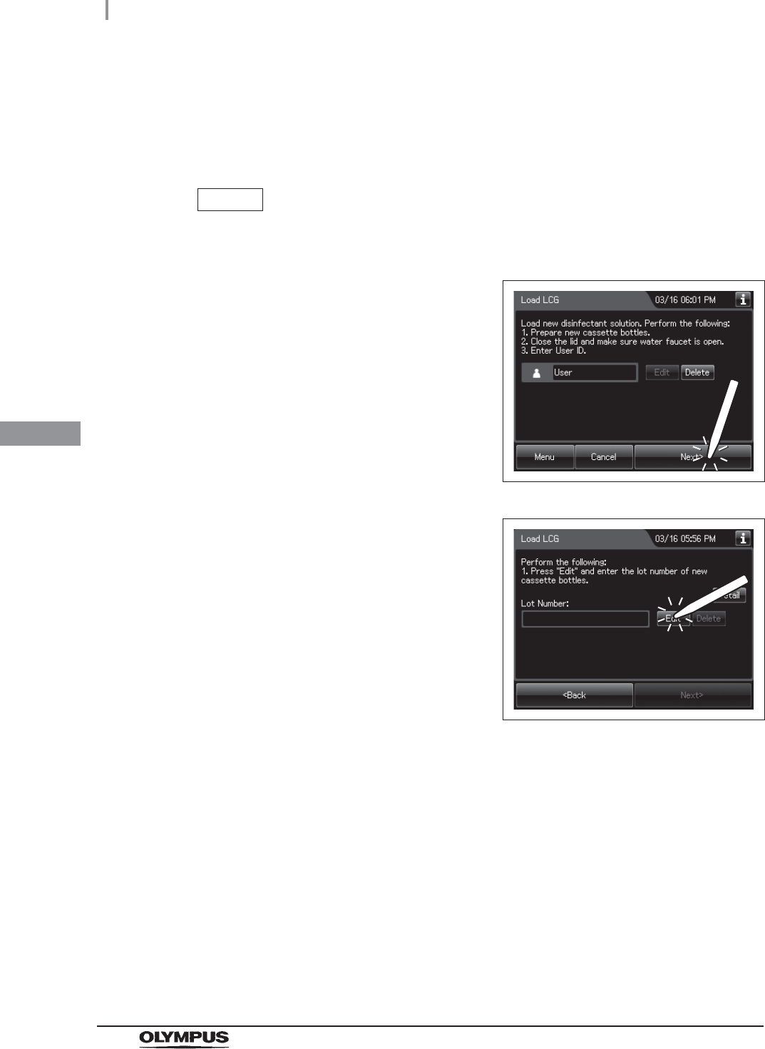
1If the shelf-life and/or lot number management
of the disinfectant solution are activated, the
touch screen displays a screen as shown in
following figure at Step 7 in “Setup of the
disinfectant solution” on page 136. Press the
“Next” button. If the lot number management of
the disinfectant solution is activated, go to Step
2. If the lot number management of the
disinfectant solution is inactivated, go to Step 5.
Figure 4.154
2Press the “Edit” button to display the lot entry
screen.
Figure 4.155
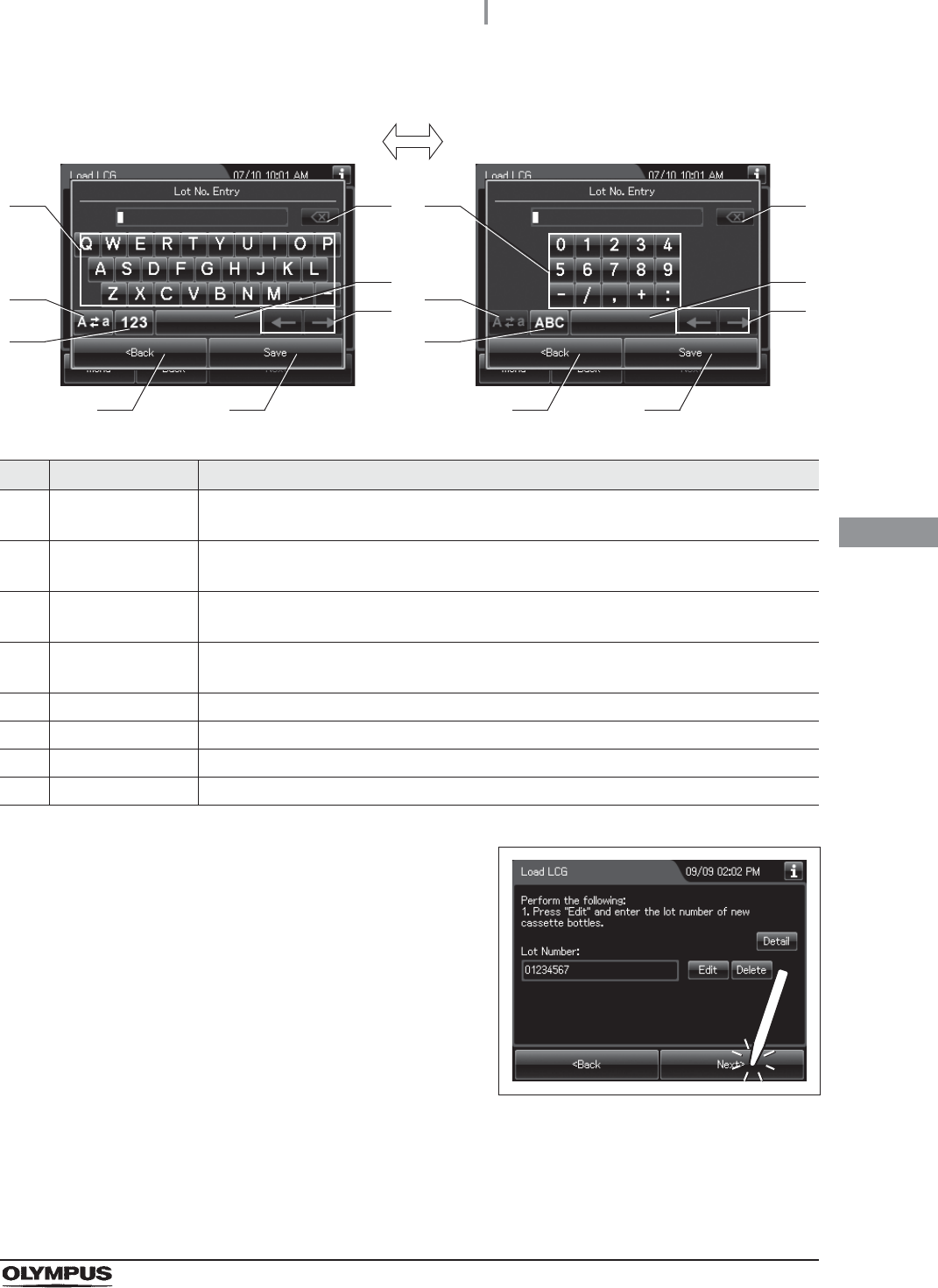
3Enter the lot number of the disinfectant solution by the software keyboard on the
touch screen and press the “Save” button.
4.20 Setup of the disinfectant solution
143
OER-Elite INSTALLATION MANUAL
Ch.4
No. Button Note
1 Alphabet/Numeral
key
Enter the alphabet or a numeral.
2 Uppercase/Lowerc
ase button
Press “Uppercase/lowercase button” to switch alphabet character on the soft keyboard
between uppercases character s and lowercase characters.
3 Numeric/Alphabetic
button
Press “Numeric or Alphabetic button” to switch the input mode between a numeral and
the alphabet.
4 Back space button Press the “Backspace button” to delete the left character of a cursor.
When a cursor is on the leftmost, this button becomes gray and cannot be pressed.
5 Space button Press to the “Space button” to insert a space character.
6 Cursor move button Press to the cursor move button to move a cursor to left or right.
7 Back button Return to the previous screen without saving the setting value.
8 Save button Return to the previous screen and save the entered value.
4Press the “Next” button. If the shelf-life
management of the disinfectant solution is
activated, go to Step 5. If the shelf-life
management of the disinfectant solution is
inactivated, go to Step 6.
Figure 4.156
41
2
3
5
6
7 8
41
2
3
5
6
7 8
Alphabet input Numeral input
144
4.20 Setup of the disinfectant solution
OER-Elite INSTALLATION MANUAL
Ch.4
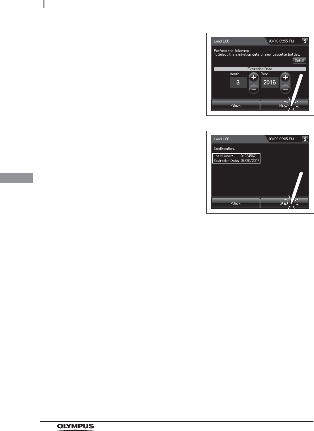
5Enter the Expiration Date of the disinfectant
solution. Press the “+” button to increase or the
“–” button to decrease. And then press the
“Next” button.
Figure 4.157
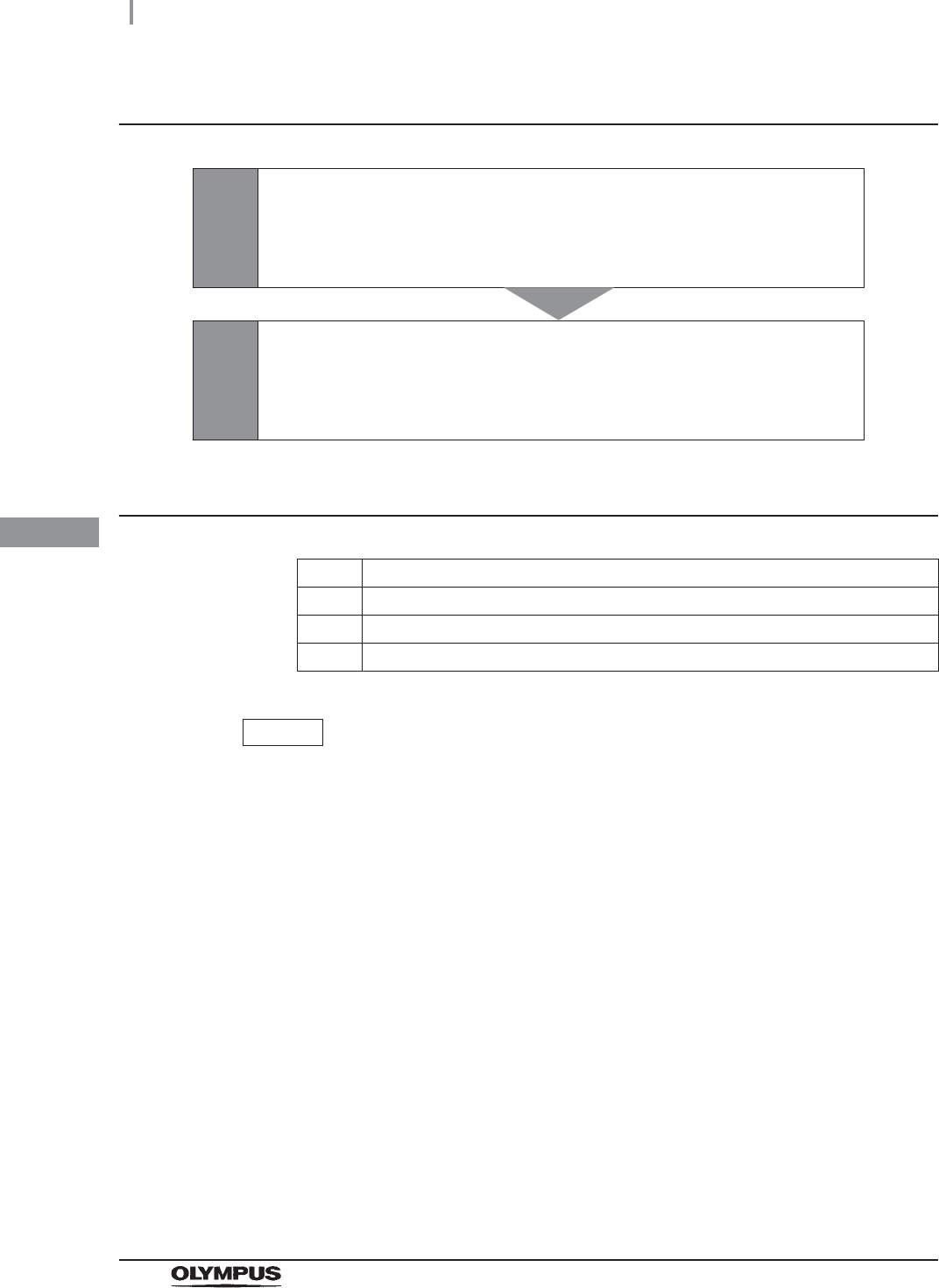
6Check the displayed lot number and press the
“Start” button. Go to Step 8 in “Setup of the
disinfectant solution” on page 136.
Figure 4.158

4.21 Self disinfection and check the operation
145
OER-Elite INSTALLATION MANUAL
Ch.4
This process is to disinfect the internal lines of the equipment and check the operation of the
equipment.
Before reprocessing, be sure to check that the disinfectant solution has an effective concentration by
using a test strip. (Refer to Section 3.7, “Checking the MRC level and entering the check result” in
“Instructions-Operation Manual”.) Be sure to replace the disinfectant solution when it fails to meet the
Minimum Recommended Concentration as specified by the manufacturer.
WARNING
• Before handling the disinfectant solution, read the cautions carefully and use as
instructed. It is especially important to know what to do if the disinfectant solution
comes into contact with your skin.
• When handling the disinfectant solution, wear personal protective equipment to
prevent any disinfectant from getting on your skin or being inhaled. To avoid
adverse physical effects, do not to touch the disinfectant solution directly or to
inhale too much vapor. If any disinfectant solution gets in your eyes, immediately
Rinse with a large amount of fresh water and then consult a medical specialist.
Personal protective equipment, such as eyewear, face mask, moisture-resistant
clothing, and chemical-resistant gloves that fit properly and are long enough so that
your skin is not exposed. All personal protective equipment should be inspected
before use and replaced periodically before it is damaged.
• If an OER-Elite pipe is clogged or another malfunction occurs, it can prevent fluid
from entering the endoscope channel and render the endoscope reprocessing
process ineffective. Be sure to confirm the fluid jet from the connecting tube
connector hits the dome of the lid.
CAUTION
Before starting the self disinfection and check the operation, always confirm that
there is no foreign material on the ventilation openings on the gas filter cases.
Blocking the ventilation not only hinders deodorization but may also cause the
device to malfunction.
4.21 Self disinfection and check the operation
146
4.21 Self disinfection and check the operation
OER-Elite INSTALLATION MANUAL
Ch.4
Self-disinfection and check the operation workflow
Required items
Table 4.8
NOTE
For the test strip, refer to Section 2.8, “Consumable accessories (Optional)”
1
Check the MRC level.
on page 164
• If the concentration is below the minimum effective level, replace the
disinfectant solution.
2
Check the function of this equipment.
on page 154
• Check if the equipment operates properly to complete the
Self-Disinfection.
Check Required items
FDA-cleared chemical indicator (test strip)
Connector jig
User ID card
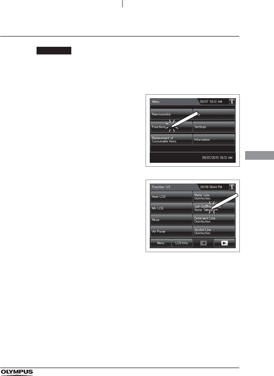
4.21 Self disinfection and check the operation
147
OER-Elite INSTALLATION MANUAL
Ch.4
Checking the MRC level and entering the check result
CAUTION
Do not collect the drained disinfectant solution from the disinfectant removal port to
check the MRC. Otherwise, the disinfectant solution in the disinfectant solution tank
would decrease, making it impossible to start the reprocessing.
1Press the “Functions” button on the Menu
screen.
Figure 4.159
2Press the “Self-Disinfection & Water Sampling”
button.
Figure 4.160
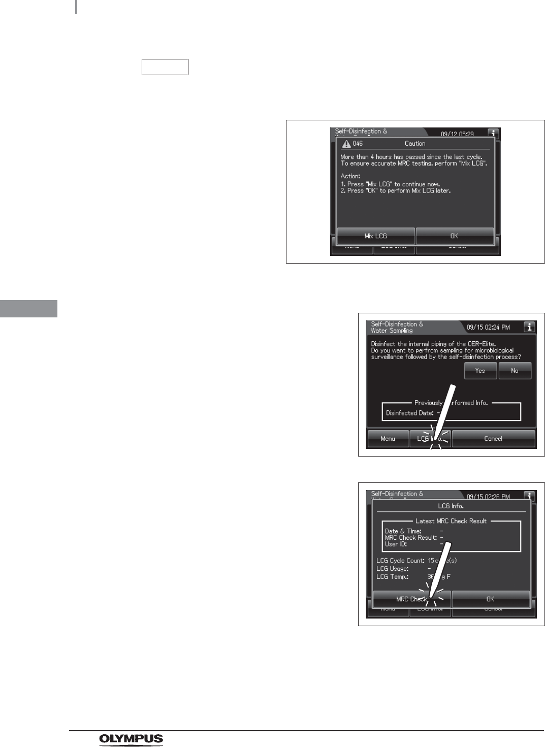
148
4.21 Self disinfection and check the operation
OER-Elite INSTALLATION MANUAL
Ch.4
NOTE
When a touch screen displays a screen as shown in the following figure, perform
the LCG Mixing. For details, refer to “Mix LCG” on page 152.
Figure 4.161
3Press the “LCG Info.” Button.
Figure 4.162
4Press the “MRC Check” button.
Figure 4.163
5Step on the foot pedal to open the lid.
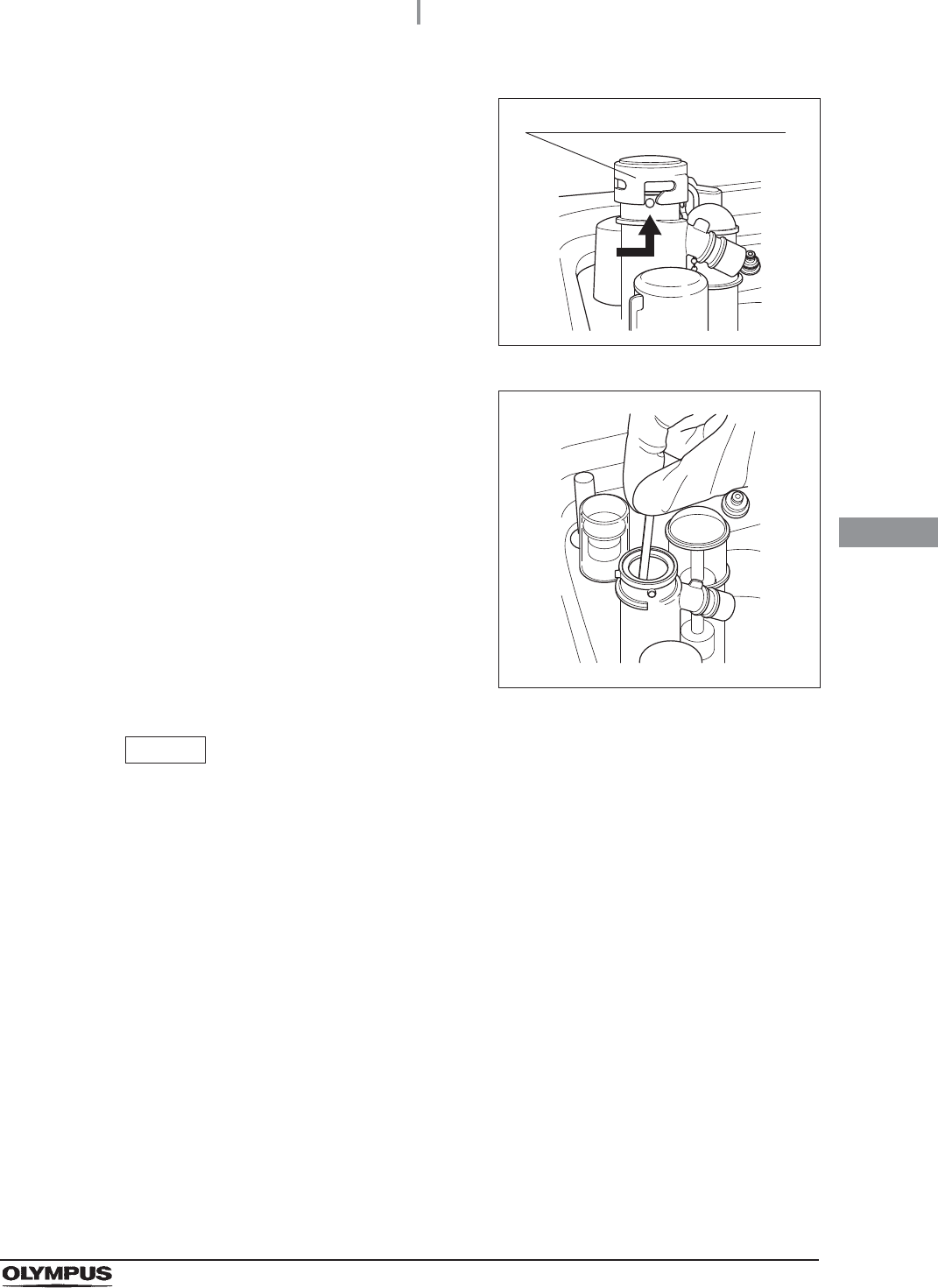
4.21 Self disinfection and check the operation
149
OER-Elite INSTALLATION MANUAL
Ch.4
6Uncap the disinfectant solution nozzle of the
reprocessing basin by turning the disinfectant
solution nozzle cap in the direction shown right.
Figure 4.164
7Insert a test strip all the way into the
disinfectant nozzle and check the concentration
as described in the instruction manual for the
test strip. If the concentration is below the
minimum effective level, replace the
disinfectant solution as described in Section
8.2, “Replacing the disinfectant solution” in
“Instructions-Operation Manual”.
Figure 4.165
NOTE
• Under high temperature and extreme temperature fluctuations, test strip may result
in fail. In such cases, Olympus recommends performing mix LCG and check the
MRC level again.
• Depending on conditions of internal valve, there is a possibility that no disinfectant
solution exist in the disinfectant solution nozzle. In the following cases, perform the
mix LCG, then check the MRC level again.
No reaction is observed on the chemical indicator after checking the MRC level.
Reaction is observed only from the edge parts of the chemical indicator after
checking the MRC level.
If the disinfectant solution in the disinfectant solution nozzle is found insufficient for
checking the MRC level on a regular basis, contact Olympus.
Disinfectant solution nozzle cap
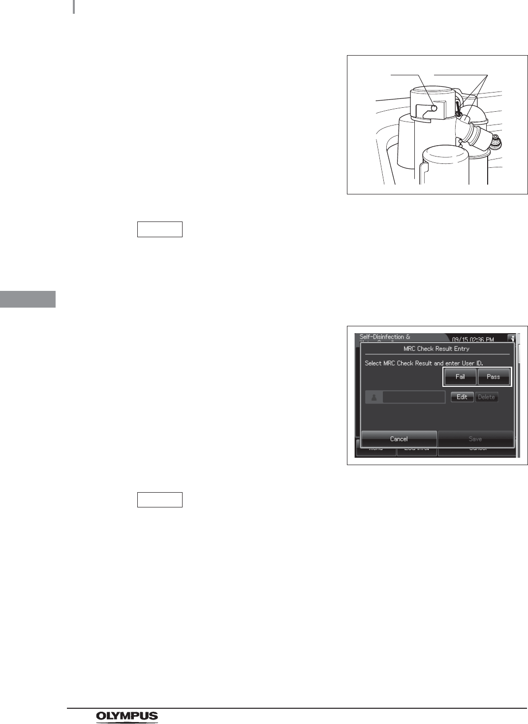
150
4.21 Self disinfection and check the operation
OER-Elite INSTALLATION MANUAL
Ch.4
8Attach the disinfectant solution nozzle cap to
the original position above the disinfectant
solution nozzle. Make sure that the pin backs in
original position, and the projection of the
disinfectant solution nozzle cap is aligned to the
projection of the disinfectant solution nozzle.
Figure 4.166
NOTE
Be sure to return the disinfectant solution nozzle cap in the original position.
Otherwise, the disinfectant solution inside the nozzle may be diluted in the next
process and next MRC check will be failed even if the concentration of LCG in the
tank is above its MRC. In this case, perform mix LCG, then check MRC again.
9Select the result of the MRC level.
Figure 4.167
NOTE
• The currently selected button is highlighted.
• If you select “Fail”, the process cannot be started.
Pin projection
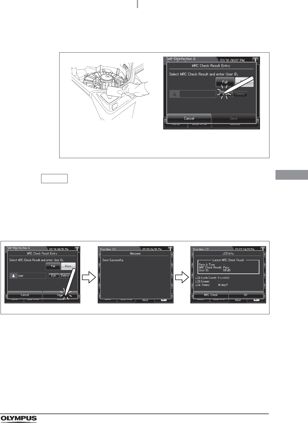
4.21 Self disinfection and check the operation
151
OER-Elite INSTALLATION MANUAL
Ch.4
10 Enter the operator's user ID. For the detailed procedures, refer to Section 3.6,
“Entering ID” in “Instructions-Operation Manual” (If applicable).
Figure 4.168
NOTE
• The input of the User ID can be omitted by modifying the User ID input setting. For
details, refer to Section 4.5, “User ID Setting” in “Instructions-Operation Manual”.
• If the “Delete” button is pressed, the entered ID can be deleted.
11 Press the “Save” button. The touch screen displays as shown in the following figure.
Figure 4.169
When the User ID entered by RFID
When the User ID is entered by the
software keyboard or called from
registered users
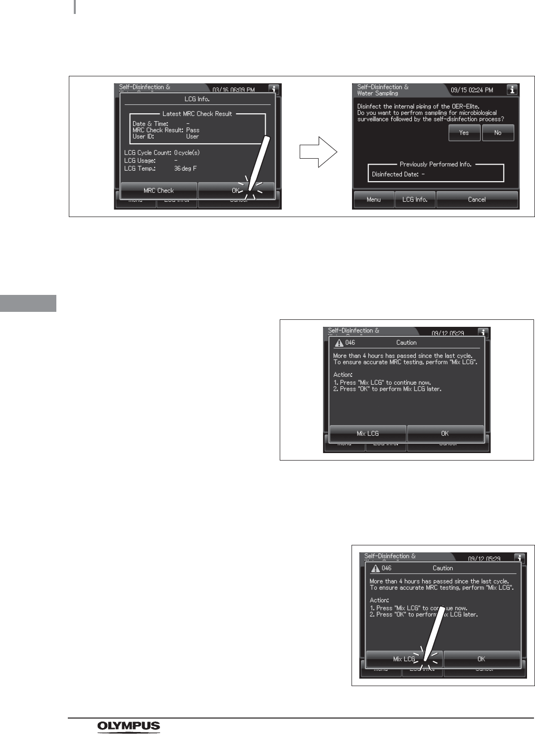
152
4.21 Self disinfection and check the operation
OER-Elite INSTALLATION MANUAL
Ch.4
Mix LCG
If the touch screen displays a screen as shown in following figure, perform the LCG Mixing by
using the following procedure.
Figure 4.171
12 Press the “OK” button.
Figure 4.170
1Make sure that the water faucet is open.
2Close the lid.
3Press the “Mix LCG” button to close the
message.
Figure 4.172
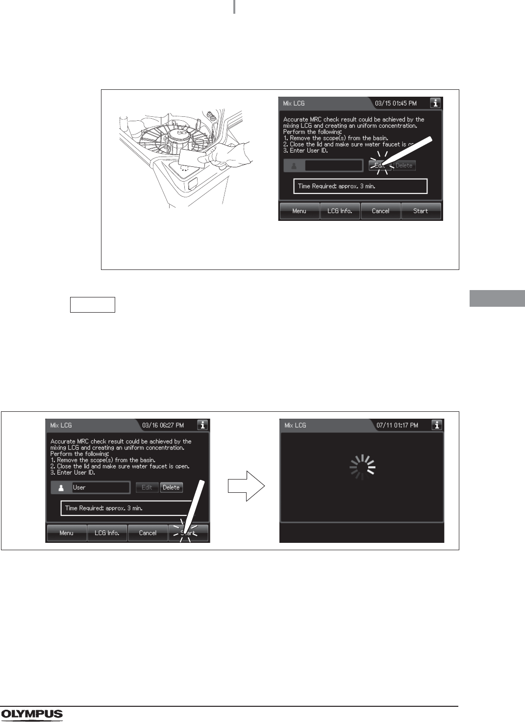
4.21 Self disinfection and check the operation
153
OER-Elite INSTALLATION MANUAL
Ch.4
4Enter the operator's user ID. For the detailed procedures, refer to Section 3.6,
“Entering ID” in “Instructions-Operation Manual” (If applicable).
Figure 4.173
NOTE
• The input of the User ID can be omitted by modifying the User ID input setting. For
details, refer to Section 4.5, “User ID Setting” in “Instructions-Operation Manual”.
• If the “Delete” button is pressed, the entered ID can be deleted.
5Press the “Start” button. The touch screen displays as shown in the following figure.
Figure 4.174
When the User ID entered by RFID
When the User ID is entered by the
software keyboard or called from
registered users
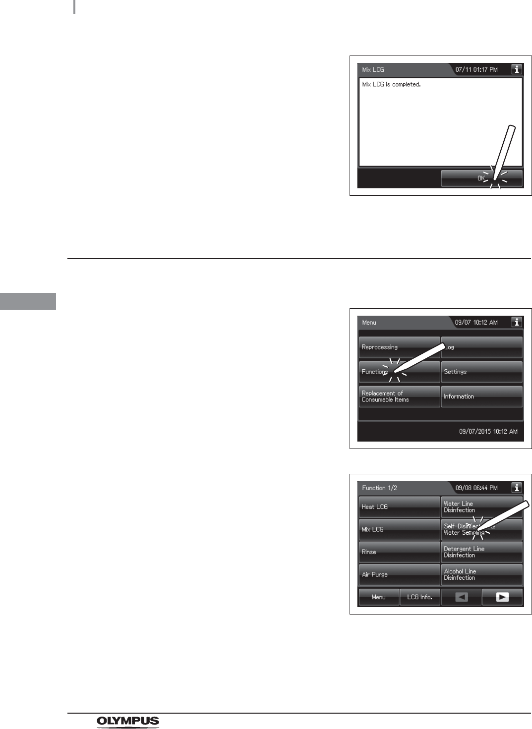
154
4.21 Self disinfection and check the operation
OER-Elite INSTALLATION MANUAL
Ch.4
Performing the self disinfection
6When the disinfectant solution mixing process
completes, the equipment generates a buzzer
beep and displays the following screen on the
touch screen. Press the “OK” button to finish.
Figure 4.175
1Make sure that the water faucet is open.
2Press the “Functions” button on the Menu
screen.
Figure 4.176
3Press the “Self-Disinfection & Water Sampling”
button.
Figure 4.177
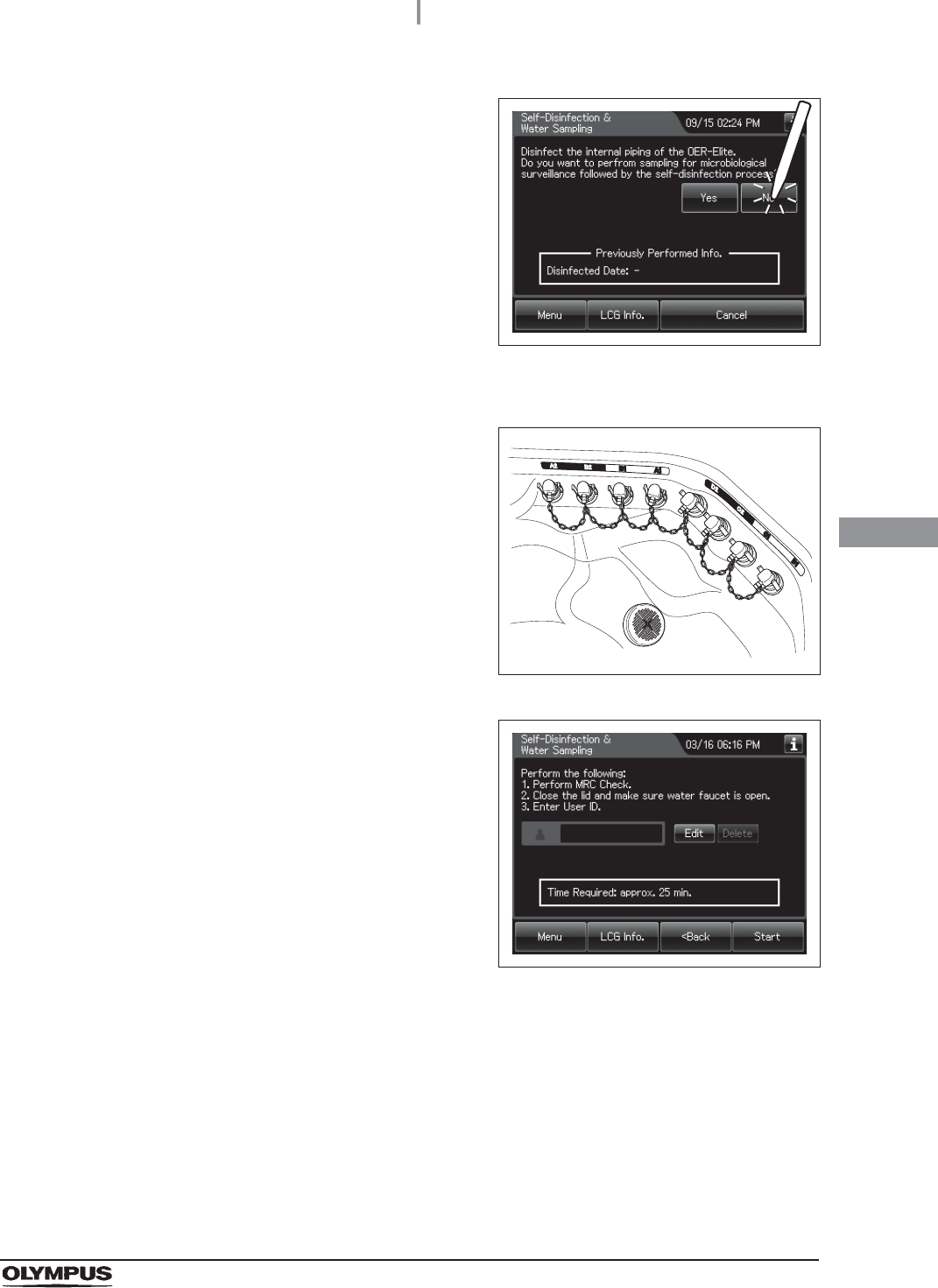
4.21 Self disinfection and check the operation
155
OER-Elite INSTALLATION MANUAL
Ch.4
4Press the “No” button.
Figure 4.178
5Step on the foot pedal to open the lid.
6Connect the connector jig to the same-colored
connector at the reprocessing basin by pushing
down on the connector jig until it clicks.
Figure 4.179
7Press the “Next” button repeatedly until the
touch screen display changes as shown below.
Figure 4.180
8Close the lid by pushing until it clicks.
9Make sure that the water faucet is open.
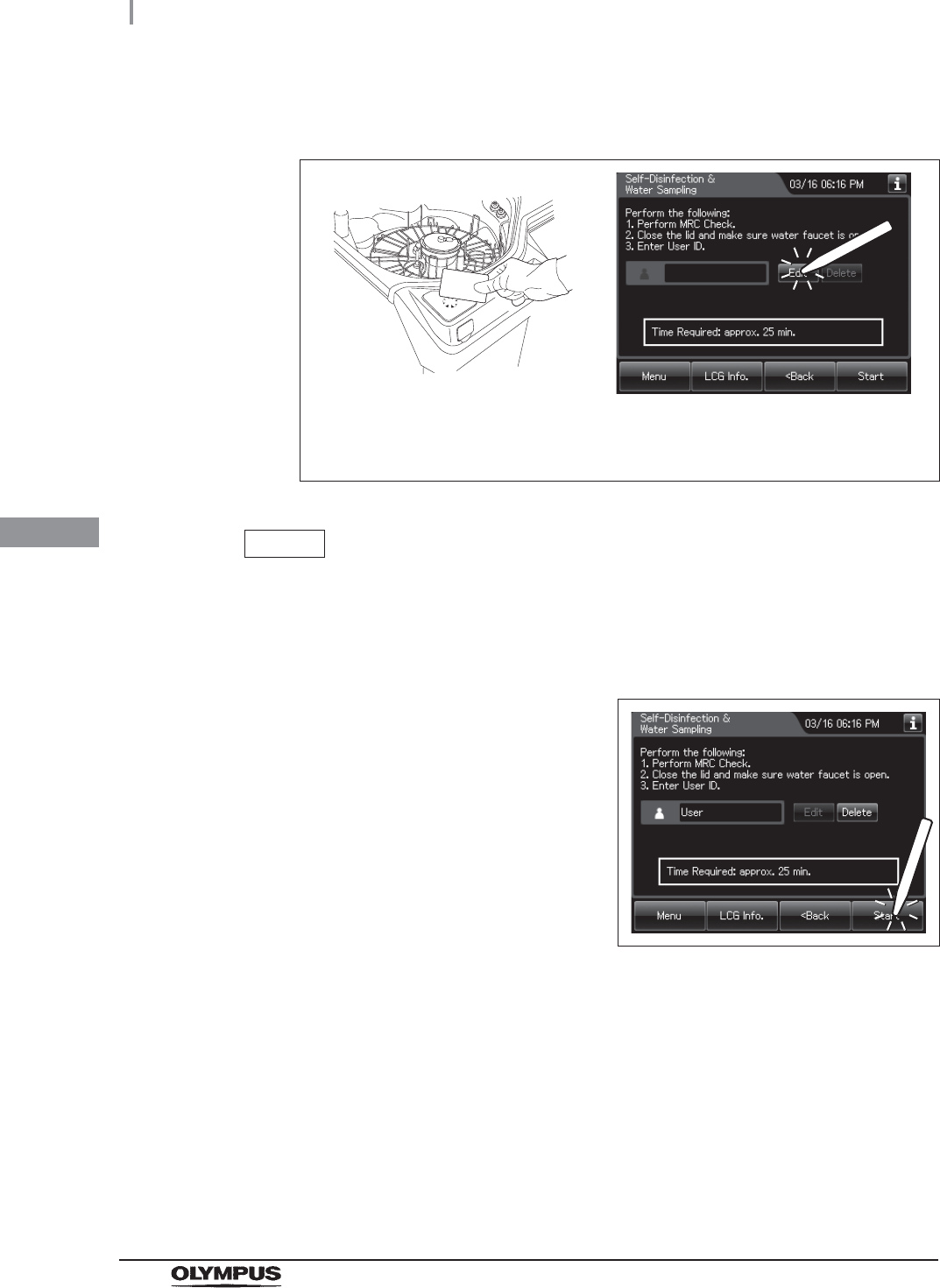
156
4.21 Self disinfection and check the operation
OER-Elite INSTALLATION MANUAL
Ch.4
10 Enter the operator's user ID. For the detailed procedures, refer to Section 3.6,
“Entering ID” in “Instructions-Operation Manual” (If applicable).
Figure 4.181
NOTE
• The input of the User ID can be omitted by modifying the User ID input setting. For
details, refer to Section 4.5, “User ID Setting” in “Instructions-Operation Manual”.
• If the “Delete” button is pressed, the entered ID can be deleted.
11 Press the “Start” button.
Figure 4.182
When the User ID entered by RFID
When the User ID is entered by the
software keyboard or called from
registered users
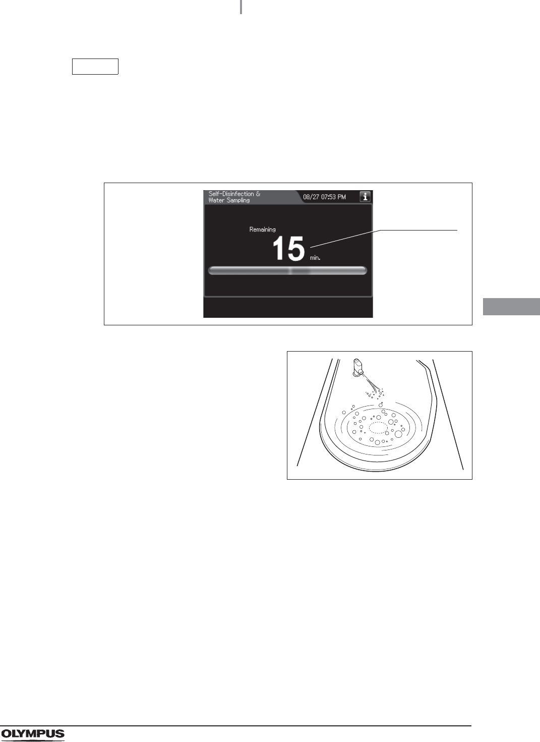
4.21 Self disinfection and check the operation
157
OER-Elite INSTALLATION MANUAL
Ch.4
NOTE
• The cleaning, disinfection and rinse are executed in the process.
• If the temperature of the disinfectant solution in the reprocessing basin is below
20qC (68qF), it will be heated to 20qC (68qF) before the disinfection process starts.
During heating, the remaining time countdown and the progress bar display stop
and turn gray. After the completion of heating, the remaining time countdown and
progress bar display resume.
Figure 4.183
12 Check that a jet of fluid is squirted from the
water supply/circulation nozzle to the dome of
lid (to check that the cleaning pump is not
clogged or abnormal).
Figure 4.184
13 Confirm the following points during reprocessing:
• That no water Leaks from the water supply hose connector.
• That no water Leaks from the drain hose connector.
• That no water Leaks from the water filter housing and the surroundings.
• That no water Leaks from the lid and surroundings.
• That no water Leaks from the lower part of the equipment.
• That there are no abnormal noises.
Displays the
remaining time
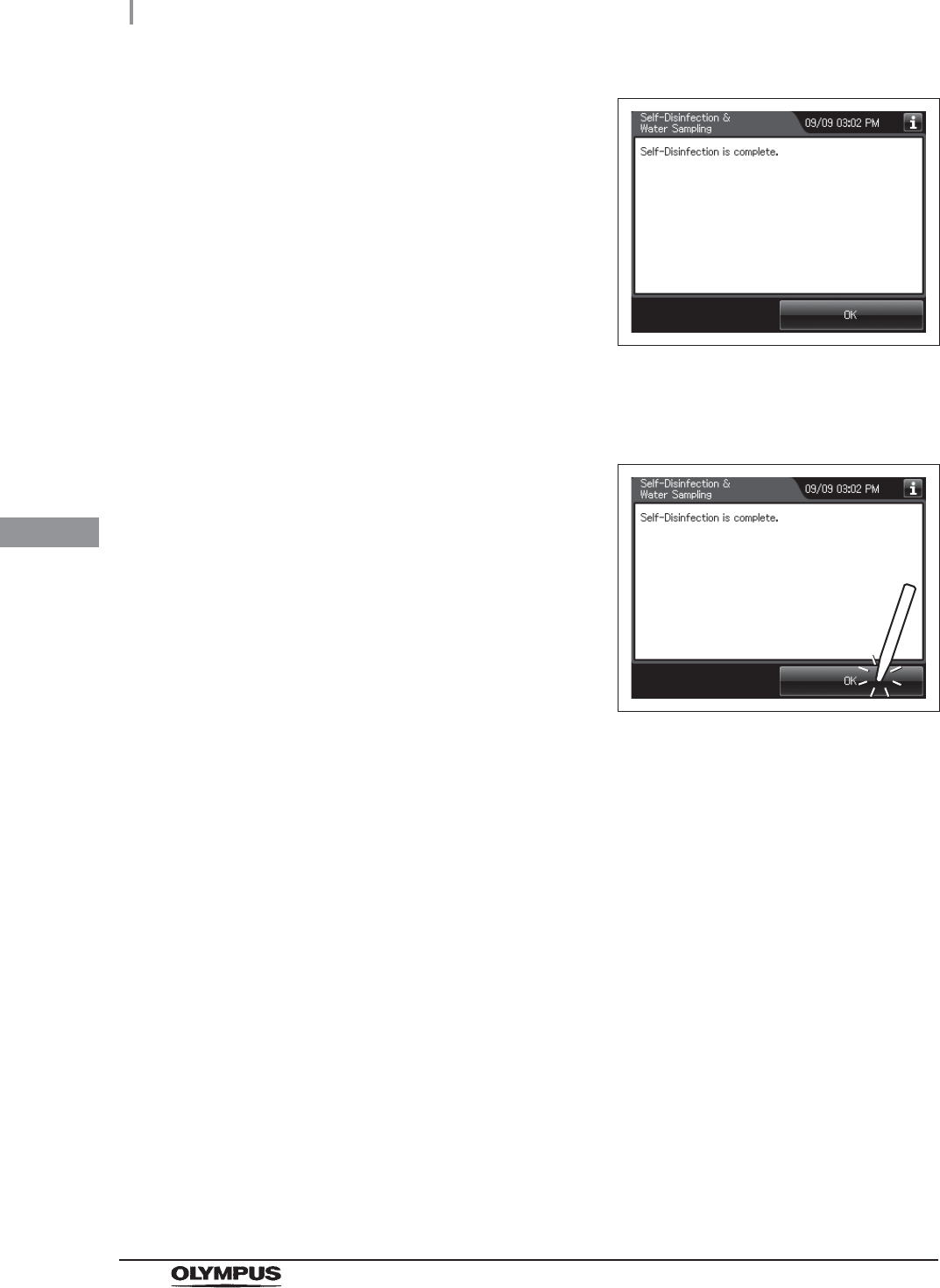
158
4.21 Self disinfection and check the operation
OER-Elite INSTALLATION MANUAL
Ch.4
14 When the self-disinfection is finished, the
buzzer beeps and the touch screen displays a
screen as shown in the following figure.
Figure 4.185
15 Step the foot pedal to open the lid.
16 Disconnect the connector jig and close the lid.
17 Press the “OK” button.
Figure 4.186
18 Rinse the connector jig thoroughly under running water, dry them well and store them
in a clean place.
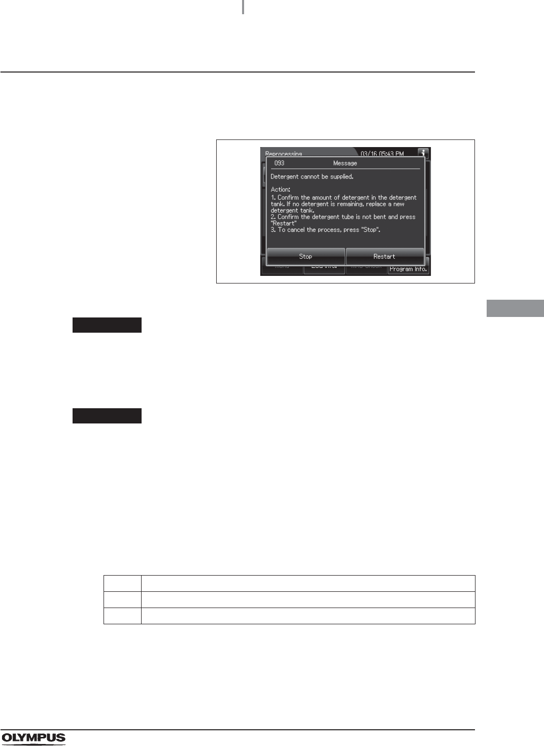
4.21 Self disinfection and check the operation
159
OER-Elite INSTALLATION MANUAL
Ch.4
When the “Message 093” is displayed
If detergent has run out and the message screen “Detergent cannot be supplied” is displayed,
the equipment will stop the process. In this case, you can restart the process from the cleaning
process by implementing the following procedure.
Figure 4.187
WARNING
When handling the detergent, read the cautions carefully and use as instructed. It
is especially important to know what measures to take if the disinfectant solution
comes into contact with your skin.
CAUTION
When handling the detergent, always wear appropriate personal protective
equipment, such as eyewear, face mask, moisture-resistant clothing, and
chemical-resistant gloves that fit properly and are long enough so that your skin is
not exposed. All personal protective equipment should be inspected before use
and replaced periodically before it is damaged.
Required items
Table 4 . 9
Solution
Refer to “When the “Message 093” is displayed” in Section 13.2, “Troubleshooting guide” in
“Instructions-Operation Manual”.
Check Required items
Syringe
Tube
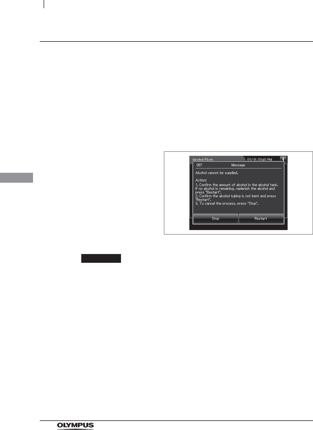
160
4.21 Self disinfection and check the operation
OER-Elite INSTALLATION MANUAL
Ch.4
When the “Message 087” is displayed
If the message screen “Alcohol cannot be supplied” is displayed and the equipment is stopped while
the detergent is still present in the detergent tank, check that there is no irregularity regarding the
following points.
• The tube connected to the alcohol tank is not kinked.
• The connector of alcohol tank is attached firmly.
If any irregularity is found by inspection, correct these points and press “Restart” button to restart the
alcohol flush process.
If any irregularity is not observed during an inspection or the message screen “Alcohol cannot be
supplied” is displayed again, internal problem with the equipment may be suspected. In this case,
follow the procedure below.
Figure 4.188
WARNING
• The alcohol used with the equipment must be 70% ethyl alcohol or 70% isopropyl
alcohol. Using any other kind of alcohol may result in malfunction of the equipment
or the endoscope, difficulty drying the endoscope, fire hazard, or a hazard due to
toxic vapor emitted from the alcohol.
• Alcohol is flammable and should be handled with extra care.
• Remove the alcohol in the alcohol tank and replace it with new alcohol at least once
a week. Otherwise, the alcohol in the alcohol tank may degrade.
• Before handling the alcohol, read the cautions carefully and use it as instructed.

4.21 Self disinfection and check the operation
161
OER-Elite INSTALLATION MANUAL
Ch.4
Required items
Table 4 . 1 0
Solution
Refer to “When the message screen “Message 087” is displayed” in Section 13.2,
“Troubleshooting guide” in “Instructions-Operation Manual”.
Check Required items
Connector jig
Syringe
Tube

162
4.22 Water line disinfection
OER-Elite INSTALLATION MANUAL
Ch.4
Disinfection of water supply piping is required in the following cases.
• Before using this equipment for the first time (after installation of the water filter).
• Immediately after replacing the water filter.
• Whenever contamination of the water supply piping has been determined.
• Before using the equipment when it has not been used for more than 14 days.
NOTE
• Olympus recommends performing microbiological sampling of the OER-Elite rinse
water quality immediately after performing the water supply piping disinfection if the
device has not been used for more than 14 days. For details on sampling rinse
water, refer to Section 7.9, “Self-disinfection” and water sampling in
“Instructions-Operation Manual”.
• When disinfection of water supply piping is required, Olympus recommends
performing it prior to replacement of the disinfectant solution. The disinfectant
solution must still meet the MRC using the test strip. After disinfection of water
supply piping, drain the disinfectant solution according to the instructions in the
instruction manual and the facility policy. Fill the OER-Elite with fresh disinfectant
solution prior to proceeding with endoscope reprocessing.
• There may be instances when the water supply lines are disinfected using fresh
disinfectant for the first time. Following disinfection of the water supply piping with
fresh disinfectant, the quantity of disinfectant solution might be reduced preventing
use of the fresh disinfectant for endoscope reprocessing. In this case, additional
fresh disinfectant can be added to the OER-Elite only when using the ready-to-use
disinfectant prepared by top loading. Adding fresh disinfectant to increase the
volume of the existing fresh disinfectant will achieve typical usage conditions.
The disinfectant solution stored in the equipment is used for disinfection of the water supply piping.
WARNING
• Before disinfecting the water supply piping, check the concentration of the
disinfectant solution with the Test Strip, and replace the disinfectant solution if the
disinfectant efficacy has been determined to be below the required level. If this
check is not applied, disinfection may be insufficient.
• Disinfection of the water supply piping is required each time the water filter is
replaced (at least once every month). Otherwise, the rinse water may be
contaminated.
4.22 Water line disinfection

4.22 Water line disinfection
163
OER-Elite INSTALLATION MANUAL
Ch.4
WARNING
• Disconnect the connecting tubes from the connectors on the equipment before
disinfecting the water supply piping. Otherwise, a jet of disinfectant solution may
squirt out from the connecting tubes and leak from a connector such as the gas
filter case connector.
• Before handling the disinfectant solution, read the cautions carefully and use as
instructed. It is especially important to know what to do if the disinfectant solution
comes into contact with your skin.
• When handling the disinfectant solution, wear personal protective equipment to
prevent any disinfectant from getting on your skin or being inhaled. To avoid
adverse physical effects, do not to touch the disinfectant solution directly or to
inhale too much vapor. If any disinfectant solution gets in your eyes, immediately
rinse with a large amount of fresh water and then consult a medical specialist. Such
protective equipment should include appropriate eyewear, face mask, cap,
moisture-resistant clothing, shoe covers, and chemical-resistant gloves that fit
properly and are long enough to prevent skin exposure. All personal protective
equipment should be inspected before use and replaced periodically before it is
damaged.
NOTE
• For details on replacing the disinfectant solution, refer to Section 4.20, “Setup of
the disinfectant solution”.
• Disinfecting the water supply piping also disinfects the water filter and other
components in the piping.
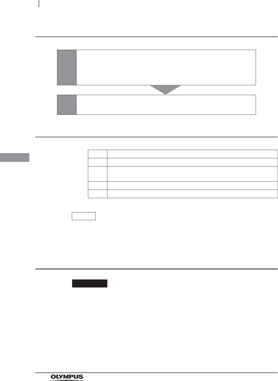
164
4.22 Water line disinfection
OER-Elite INSTALLATION MANUAL
Ch.4
Disinfection of water supply piping workflow
Required items
Table 4.11
NOTE
For details on the test strip, refer to Section 2.8, “Consumable accessories
(Optional)”.
Checking the MRC level and entering the check result
CAUTION
Do not collect the drained disinfectant solution from the disinfectant removal port to
check the MRC. Otherwise, the disinfectant solution in the disinfectant solution tank
would decrease, making it impossible to start the reprocessing.
1
Check the MRC level.
on page 164
• If the concentration is below the minimum effective level, replace the
disinfectant solution
2Disinfect the water supply piping.
on page 172
Check Required items
Chemical indicator (test strip)
Container with 2 L (67 ounces) or larger capacity (wide-mouthed container such
as a vat)
Filter tube (× 2)
Water supply piping disinfection hose
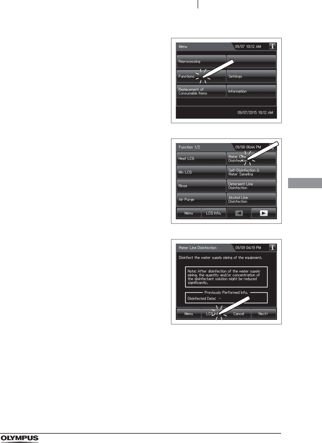
4.22 Water line disinfection
165
OER-Elite INSTALLATION MANUAL
Ch.4
1Press the “Functions” button on the Menu
screen.
Figure 4.189
2Press the “Water Line Disinfection”.
Figure 4.190
3Press the “LCG Info.” Button.
Figure 4.191
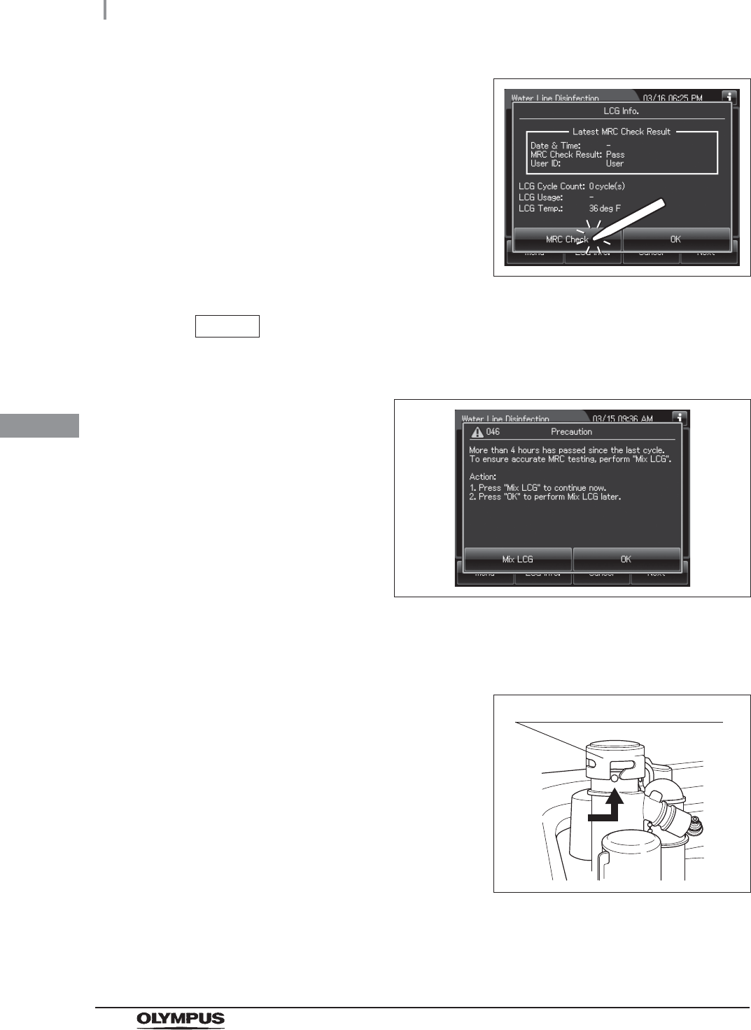
166
4.22 Water line disinfection
OER-Elite INSTALLATION MANUAL
Ch.4
4Press the “MRC Check Result” button to
display the MRC Check Result entry screen.
Figure 4.192
NOTE
When a touch screen displays a screen as shown in the following figure, perform
the LCG Mixing. For details, refer to “LCG Mixing” on page 169.
Figure 4.193
5Step on the foot pedal to open the lid.
6Turn the disinfectant solution nozzle cap in the
direction shown to remove, refer to the
Figure 4.194.
Figure 4.194
Disinfectant solution nozzle cap
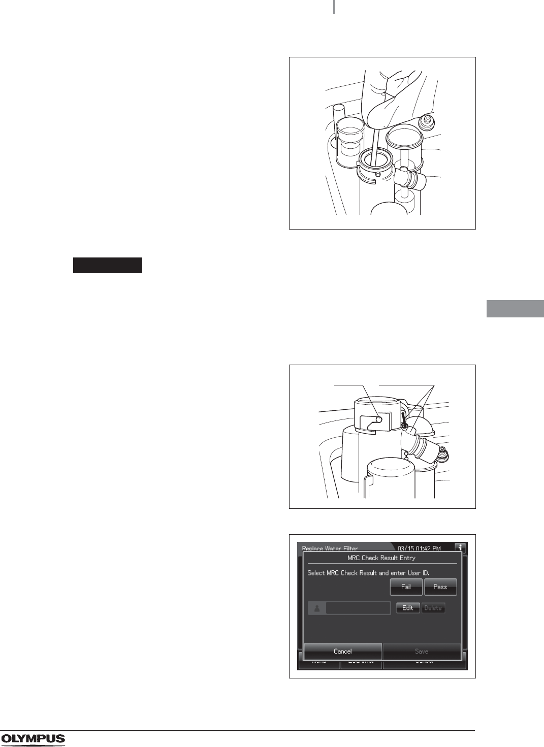
4.22 Water line disinfection
167
OER-Elite INSTALLATION MANUAL
Ch.4
7Insert a test strip all the way into the
disinfectant nozzle and check the MRC level
according to the instructions manual of the test
strip. If the concentration is below the minimum
effective level, replace the disinfectant solution
as described in Section 8.2, “Replacing the
disinfectant solution” in “Instructions-Operation
Manual”.
Figure 4.195
WARNING
Be sure to attach the disinfectant solution nozzle cap to the original position above
the disinfectant solution nozzle. There is a risk that water penetrates in the
disinfectant nozzle during the process, in which case the disinfectant concentration
cannot be checked correctly.
8Attach the disinfectant solution nozzle cap to
the original position above the disinfectant
solution nozzle. Make sure that the pin backs in
original position, and the projection of the
disinfectant solution nozzle cap is aligned to the
projection of the disinfectant solution nozzle.
Figure 4.196
9Select the result of the MRC level. If you select
“Fail”, the process cannot be started.
Figure 4.197
Pin projection

168
4.22 Water line disinfection
OER-Elite INSTALLATION MANUAL
Ch.4
NOTE
The currently selected button is highlighted.
10 Enter the operator's user ID. For the detailed procedures, refer to Section 3.6,
“Entering ID” in “Instructions-Operation Manual” (If applicable).
Figure 4.198
NOTE
• The input of the User ID can be omitted by modifying the User ID input setting. For
details, refer to Section 4.5, “User ID Setting” in “Instructions-Operation Manual”.
• If the “Delete” button is pressed, the entered ID can be deleted.
11 Press the “Save” button. The touch screen displays as shown in the following figure.
Figure 4.199
When the User ID entered by RFID
When the User ID is entered by the
software keyboard or called from
registered users
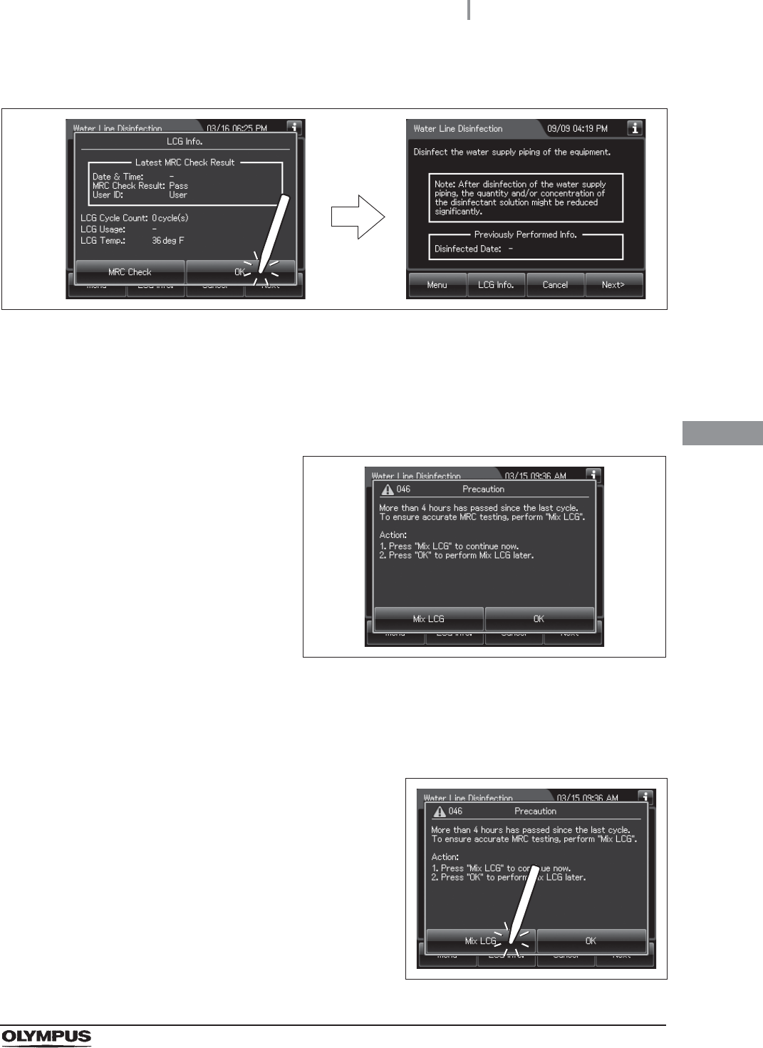
4.22 Water line disinfection
169
OER-Elite INSTALLATION MANUAL
Ch.4
LCG Mixing
If the touch screen displays a screen as shown in following figure, perform the LCG Mixing by
using the following procedure.
Figure 4.201
12 Press the “OK” button.
Figure 4.200
1Make sure the water faucet is open.
2Close the lid.
3Press the “Mix LCG” button to close the
message.
Figure 4.202
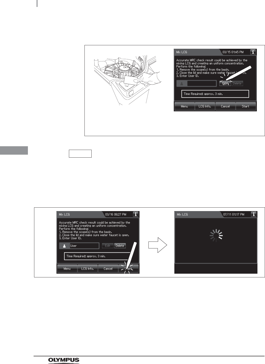
170
4.22 Water line disinfection
OER-Elite INSTALLATION MANUAL
Ch.4
4Enter the operator's user ID. For the detailed procedures, refer to Section 3.6,
“Entering ID” in “Instructions-Operation Manual” (If applicable).
Figure 4.203
NOTE
• The input of the User ID can be omitted by modifying the User ID input setting. For
details, refer to Section 4.5, “User ID Setting” in “Instructions-Operation Manual”.
• If the “Delete” button is pressed, the entered ID can be deleted.
5Press the “Start” button. Disinfectant solution mixing starts.
Figure 4.204
When the User ID entered by RFID
When the User ID is entered by the
software keyboard or called from
registered users
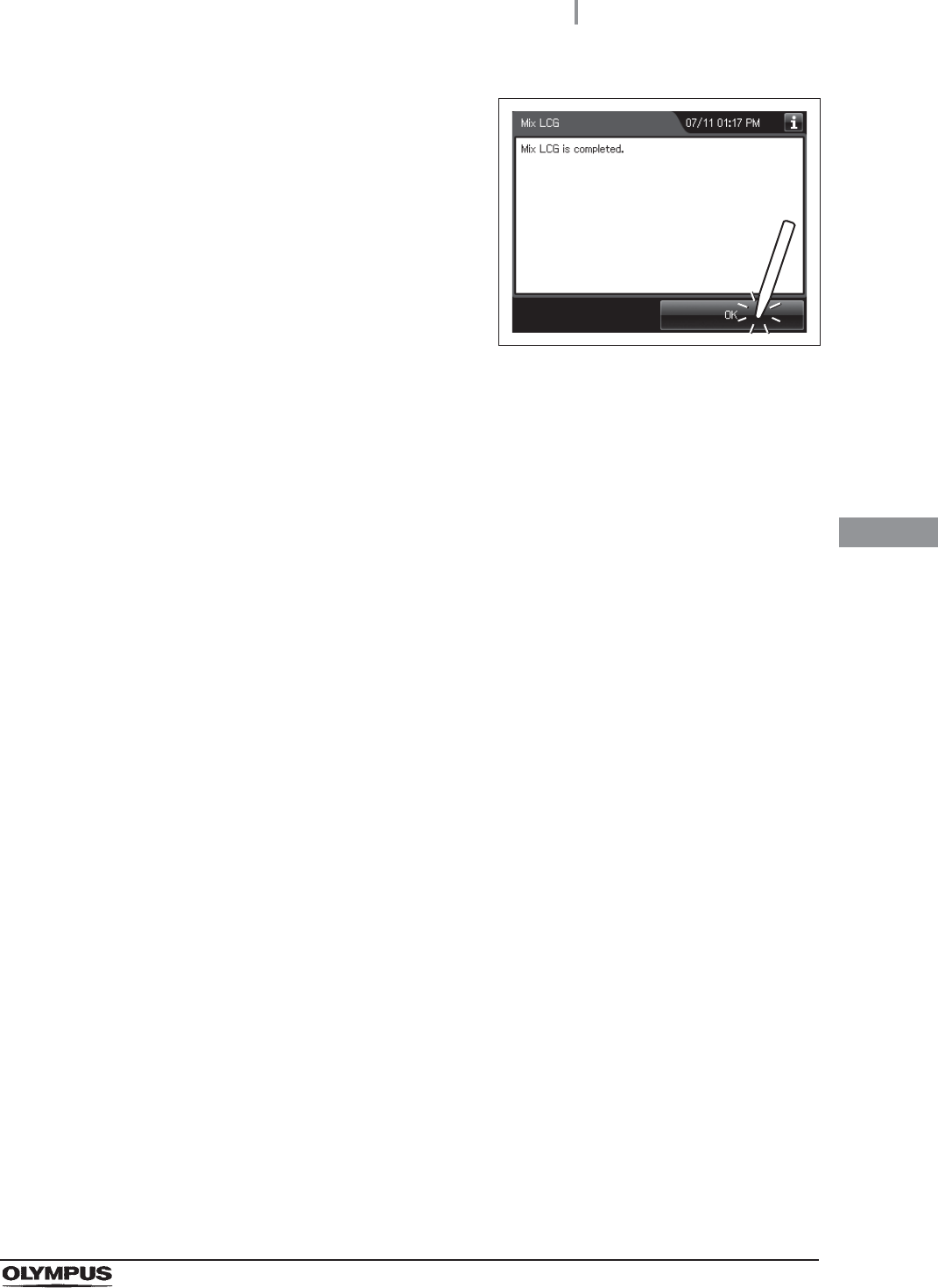
4.22 Water line disinfection
171
OER-Elite INSTALLATION MANUAL
Ch.4
6When the disinfectant solution mixing process
completes, the equipment generates a buzzer
beep and displays the following screen on the
touch screen. Press the “OK” button to finish.
Figure 4.205
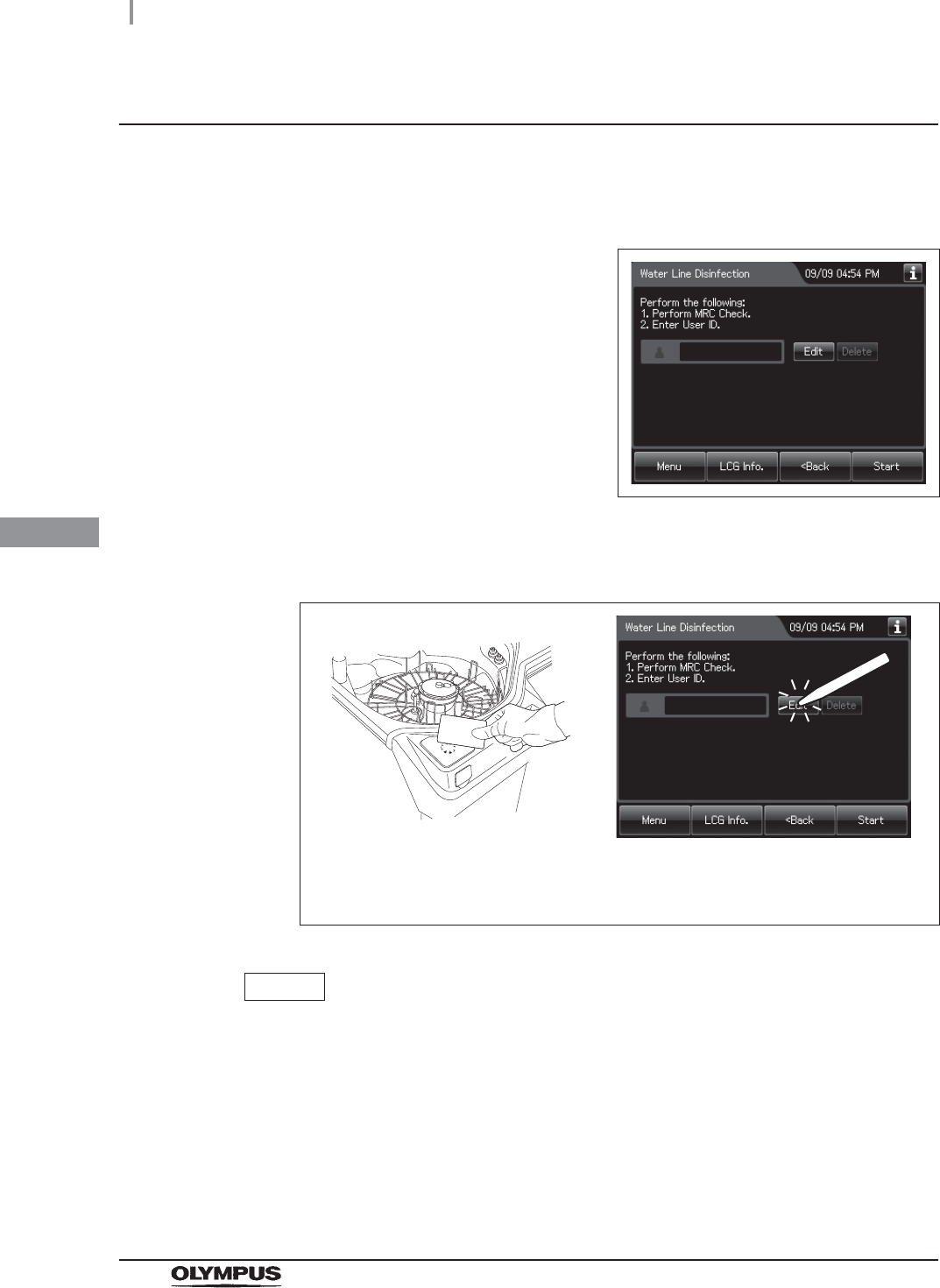
172
4.22 Water line disinfection
OER-Elite INSTALLATION MANUAL
Ch.4
Disinfecting the water line
1Make sure that the water faucet is open.
2Close the lid.
3Press the “Next” button repeatedly until the
touch screen display changes as shown below.
Figure 4.206
4Enter the operator's user ID. For the detailed procedures, refer to Section 3.6,
“Entering ID” in “Instructions-Operation Manual” (If applicable).
Figure 4.207
NOTE
• The input of the User ID can be omitted by modifying the User ID input setting. For
details, refer to Section 4.5 “User ID Setting” in “Instructions-Operation Manual”.
• If the “Delete” button is pressed, the entered ID can be deleted.
5Press the “Start” button.
6Push the area marked “PUSH” on the front door to open it.
When the User ID entered by RFID
When the User ID is entered by the
software keyboard or called from
registered users
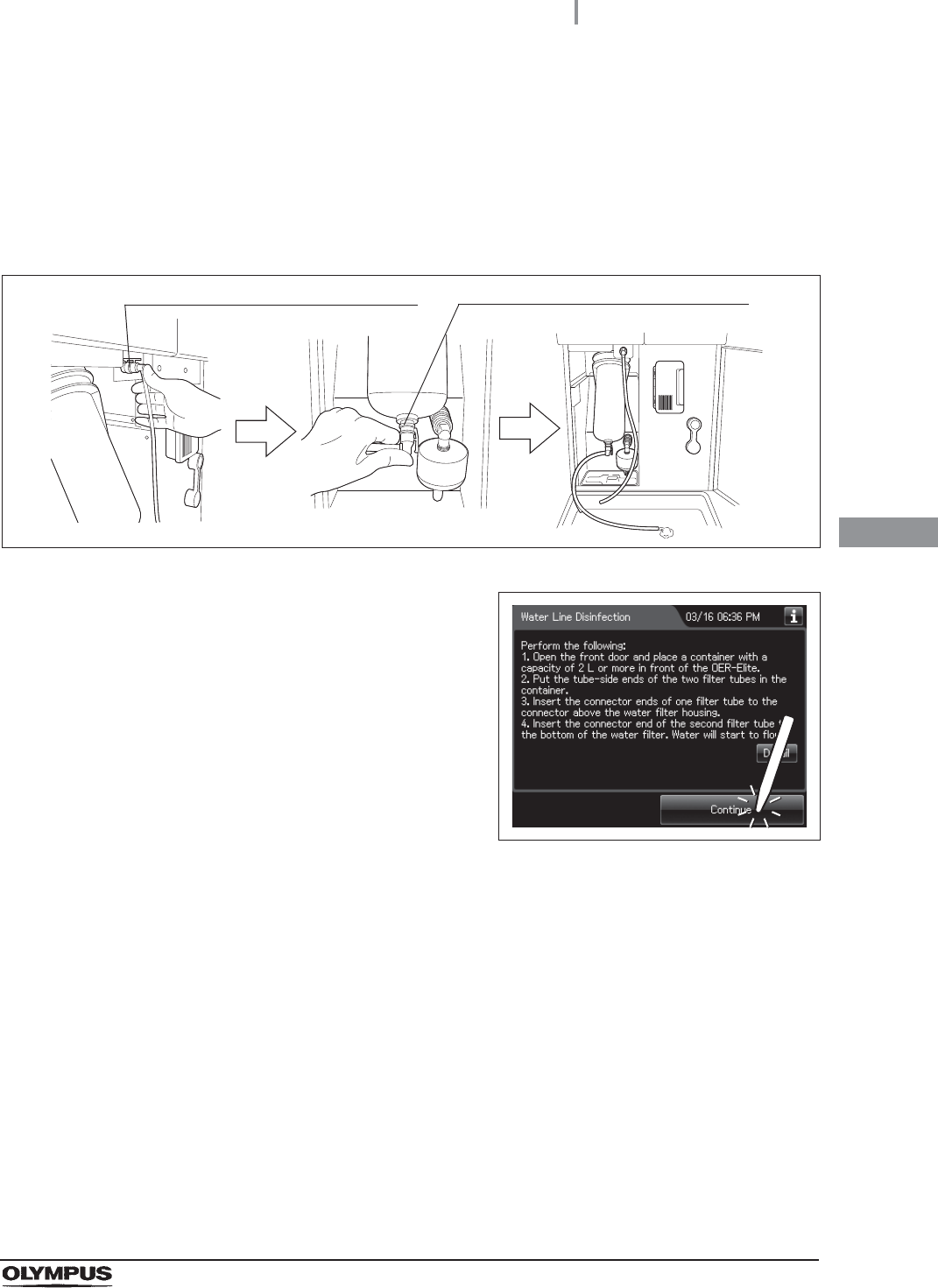
4.22 Water line disinfection
173
OER-Elite INSTALLATION MANUAL
Ch.4
7Prepare the container with a capacity of 2 L (67 ounces) or more in front of the
equipment.
8Put the tube-side ends of the two filter tubes in the container placed and insert the
connector ends of the two filter tubes into the connector above the water filter housing
and the connector below the water filter housing until they click. Water will start to flow
from the tube connected to the connector below the water filter housing.
Figure 4.208
9Press the “Continue” button.
Figure 4.209
Connector above water filter housing Connector below water filter housing
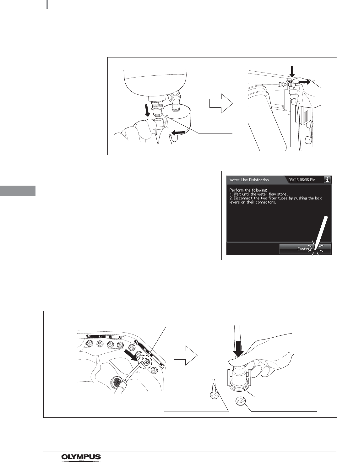
174
4.22 Water line disinfection
OER-Elite INSTALLATION MANUAL
Ch.4
10 When water flow stops, disconnect the two filter tubes by pushing the lock levers on
their connectors.
Figure 4.210
11 Press the “Continue” button.
Figure 4.211
12 Step on the foot pedal to open the lid.
13 Connect the water supply piping disinfection hose between the connector C1 in the
reprocessing basin and the water supply piping disinfection connector.
Figure 4.212
14 Close the lid.
Lock lever
Washing case mount
Temperature sensor
Connector C1
Water supply piping
disinfection connector
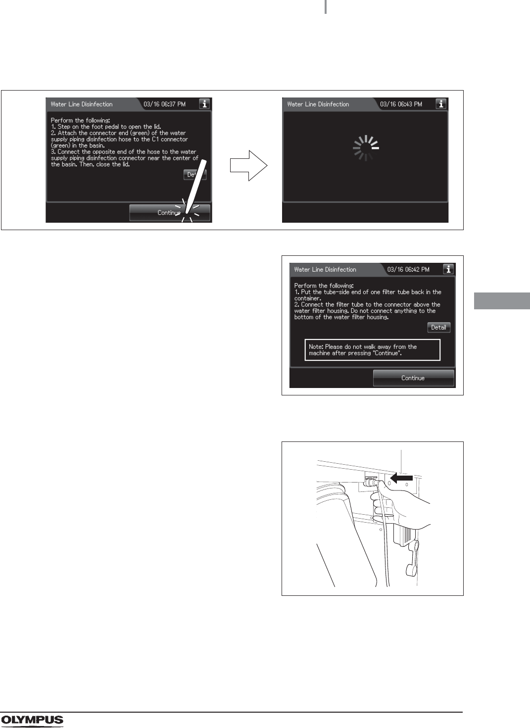
4.22 Water line disinfection
175
OER-Elite INSTALLATION MANUAL
Ch.4
15 Press the “Continue” button to supply the disinfectant solution in the reprocessing
basin.
Figure 4.213
16 When the reprocessing basin is filled with
disinfectant solution, a buzzer sounds three
times and the touch screen displays the
following screen.
Figure 4.214
17 Put the tube-side end of the filter tube and put it in the container.
18 Insert the connector end of the filter tube into
the connector above the water filter housing
until it clicks. Do not connect anything to the
connector below the water filter housing.
Figure 4.215
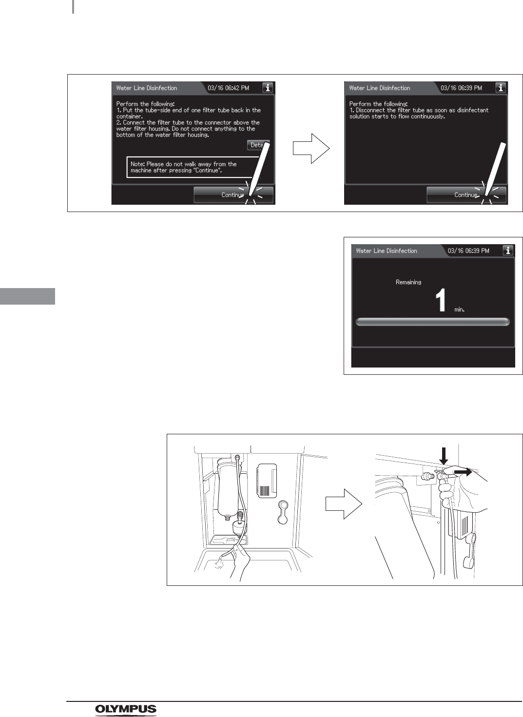
176
4.22 Water line disinfection
OER-Elite INSTALLATION MANUAL
Ch.4
19 Press the “Continue” button twice.
Figure 4.216
20 When the disinfection process starts, the touch
screen displays the remaining time and the
progress bar.
Figure 4.217
21 When water starts to flow continuously from the filter tube, disconnect the tube by
pushing its lock lever. Water flow should stop when the filter tube is disconnected.
Figure 4.218
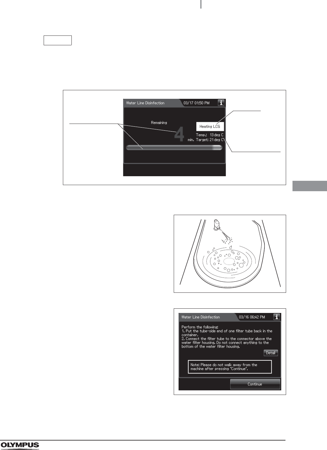
4.22 Water line disinfection
177
OER-Elite INSTALLATION MANUAL
Ch.4
NOTE
If the temperature of the disinfectant solution is less than 20qC (68qF), it will be
heated to 20qC (68qF). During heating, the remaining time countdown and the
progress bar display stop and turn gray. After the completion of heating, the
remaining time countdown and progress bar display resume.
Figure 4.219
22 Make sure that a jet of fluid is output from the
water supply/circulation nozzle to the dome of
lid during the process.
Figure 4.220
23 When the remaining time displayed on the
touch screen reaches 0 minutes, the buzzer
sounds and the touch screen displays the
following screen.
Figure 4.221
24 Put the tube-side end of the filter tube back in the container.
It blinks
Current and
target
temperature of
the disinfectant
solution
Progress stops
and turn gray
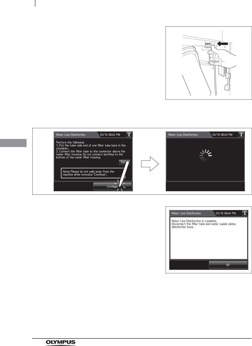
178
4.22 Water line disinfection
OER-Elite INSTALLATION MANUAL
Ch.4
25 Insert the connector end of the filter tube into
the connector above the water filter housing.
Do not connect a filter tube to the connector
below the water filter housing.
Figure 4.222
26 Press the “Continue” button. The touch screen displays a screen as shown in the
following figure and water will flow from the filter tube.
Figure 4.223
27 After several seconds, the buzzer sounds
indicating the end of the process and the touch
screen displays the following screen.
Figure 4.224
28 Disconnect the filter tube by pushing its lock lever.
29 Close the front door.
30 Step on the foot pedal to open the lid.
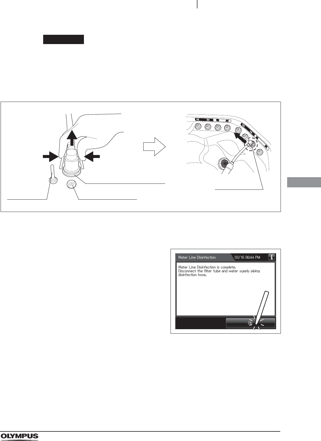
4.22 Water line disinfection
179
OER-Elite INSTALLATION MANUAL
Ch.4
WARNING
Disconnect the water supply piping disinfection hose from the connector, covering
the connector of the hose with hands in waterproof gloves. Otherwise, water
pooled inside of the hose may spill out.
31 Disconnect the water supply piping disinfection hose and close the lid.
Figure 4.225
32 Rinse the filter tube and water supply piping disinfection hose thoroughly in running
water, dry them thoroughly, and store in a clean place.
33 Press the “OK” button to complete the water
filter replacement process.
Figure 4.226
Water supply piping
disinfection hose connector
Washing case mount
Temperature
sensor
Connector C1

180
4.23 Checking the operation of optional accessories
OER-Elite INSTALLATION MANUAL
Ch.4
Checking the operation of the bar code reader (MAJ-2130)
To input the patient ID from a bar code, it is required to connect the optional MAJ-2130 bar code
reader.
For the installation of the bar code reader, refer to the Instructions - Installation Manual for this
equipment and the Instructions for the MAJ-2130 bar code reader.
CAUTION
Do not connect anything other than the designated bar code reader to the bar code
reader port. Otherwise, the IDs may not be read out correctly or the instrument may
malfunction.
NOTE
• A patient ID can be input by either bar code reader or software keyboard
(on-screen), but a patient name can be input by only software keyboard. It is
possible to input the patient name by software keyboard (on-screen) after entering
the patient ID by the bar code reader.
• The OER-Elite can read the top 23 characters of each bar code. When the bar
code contains data other than patient data, the equipment reads all of
23 characters including data other than the patient data that a bar code has.
• Do not alter the settings of the bar code reader. It has been set to the optimum
settings for combined use with this equipment. If the Settings are altered, it may be
impossible to read the bar codes, contact Olympus.
4.23 Checking the operation of optional accessories

4.23 Checking the operation of optional accessories
181
OER-Elite INSTALLATION MANUAL
Ch.4
Required items
Table 4 . 1 2
NOTE
The bar code that equipment can read is a bar code of the following standards.
UPC/EAN
Code 128
GS1-128
Code 39
Trioptic Code 39
Code 93
Code 11
Interleaved 2 of 5
Discrete 2 of 5
Codabar
MSI
Chinese 2 of 5
Matrix 2 of 5
Korean 3 of 5
Inverse 1D
GS1 DataBar
Composite Codes
Check Required items
Bar code
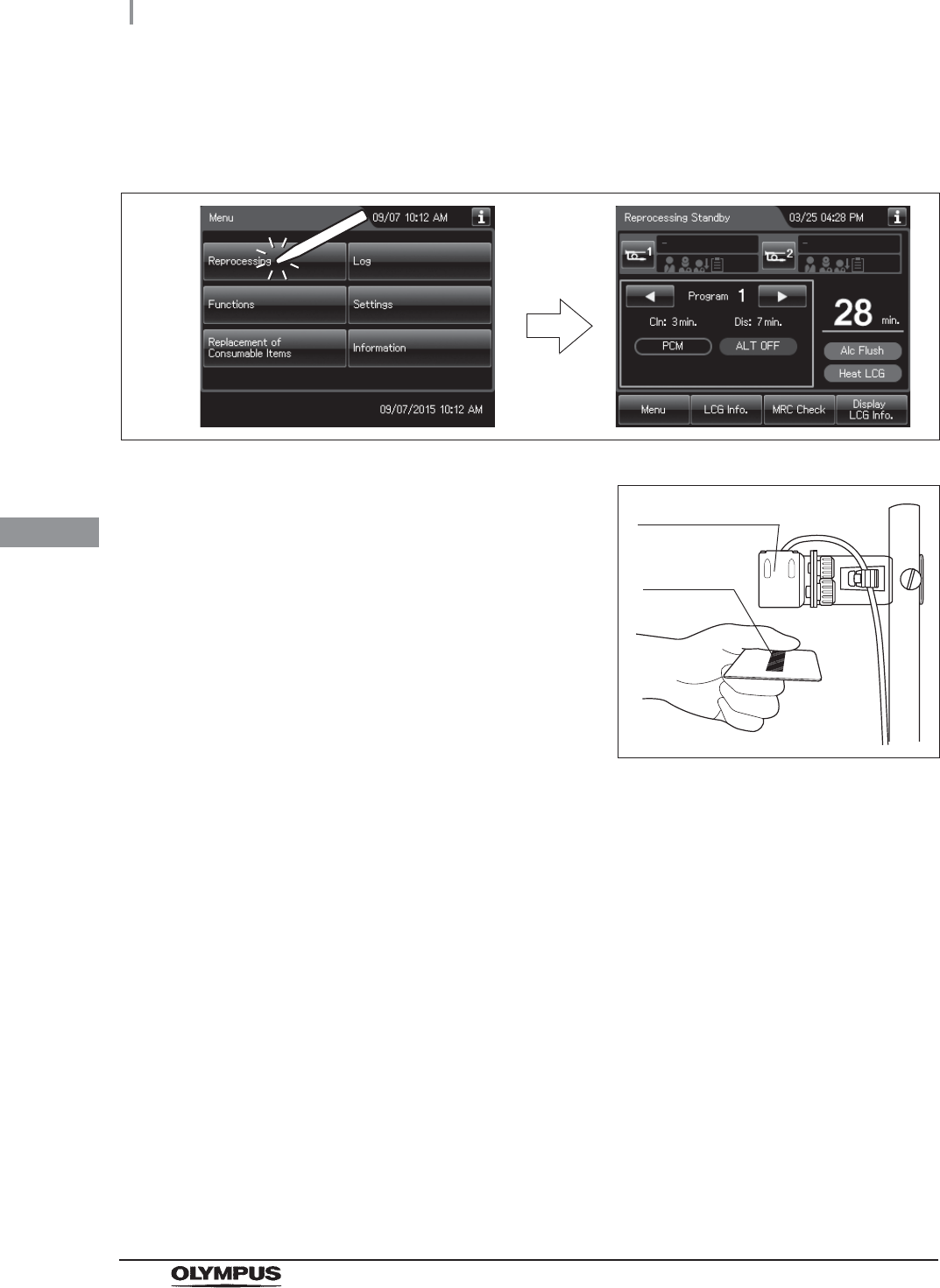
182
4.23 Checking the operation of optional accessories
OER-Elite INSTALLATION MANUAL
Ch.4
Checking the operation of the bar code reader
1Press the “Reprocessing” button to display the reprocessing standby screen.
Figure 4.227
2Place the bar code under the bar code reader
to read the bar code and adjust the distance
between them so that the entire bar code is
within the scanning area of the bar code reader.
When the bar code reader succeeds in
scanning of the bar code, the bar code reader
sounds a short beep. If the bar code reader
dose not sound a short beep, correct problems
in reference to the instruction manual for the
bar code reader MAJ-2130 or Section 13.2,
“Troubleshooting guide” in
“Instructions-Operation Manual”. Figure 4.228
Bar code reader
Bar code
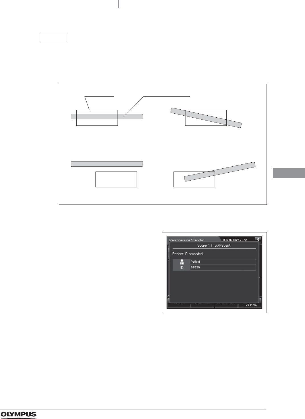
4.23 Checking the operation of optional accessories
183
OER-Elite INSTALLATION MANUAL
Ch.4
NOTE
When the bar code reader scans bar code, the bar code reader projects a green
aiming pattern. The scanning pattern of the bar code reader is formed by the
aiming pattern. When the entire bar code does not cross the scanning pattern, the
bar code reader cannot scan the entire bar code.
Figure 4.229
3Then the touch screen displays data scanning
form bar code as shown in the following figure.
Check the data of bar code on the touch
screen. If the touch screen does not display a
screen as shown in the following figure, or if the
displayed data has errors, correct problems in
reference to the instruction manual for the bar
code reader MAJ-2130 or Section 13.2,
“Troubleshooting guide” in
“Instructions-Operation Manual”.
Figure 4.230
Suitable examples
Unsuitable examples
Aiming pattern
Bar code
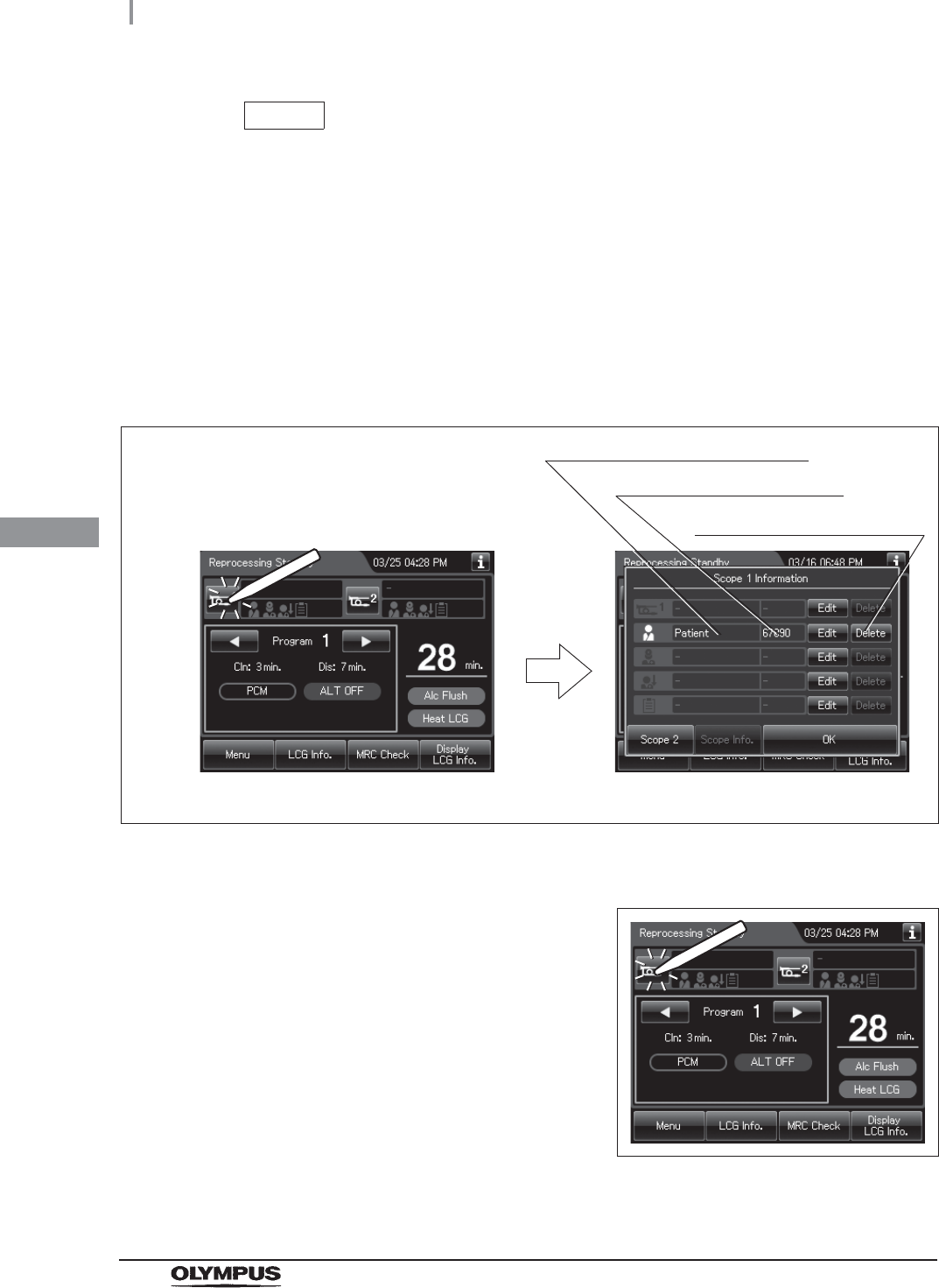
184
4.23 Checking the operation of optional accessories
OER-Elite INSTALLATION MANUAL
Ch.4
NOTE
• A patient ID can be input by either bar code reader or software keyboard
(on-screen), but a patient name can be input by only software keyboard. It is
possible to input the patient name by software keyboard (on-screen) after entering
the patient ID by the bar code reader.
• When the patient ID setting is inactivated, the touch screen does not display
information on bar code. For changing the patient ID setting, refer to Section 4.7,
“Patient ID setting” in “Instructions-Operation Manual”.
• The entered patient ID can be checked on the scope1 associated ID information
screen. Press the “Scope 1” button to display the scope1 associated ID information
screen.
Figure 4.231
4Press the “Scope 1” button on the reprocessing
standby screen to display the Scope1
associated ID information screen.
Figure 4.232
Displays ID of the patient ID
Press to delete the patient ID
Displays Name of the patient ID
Scope1 associated ID informationReprocessing standby screen
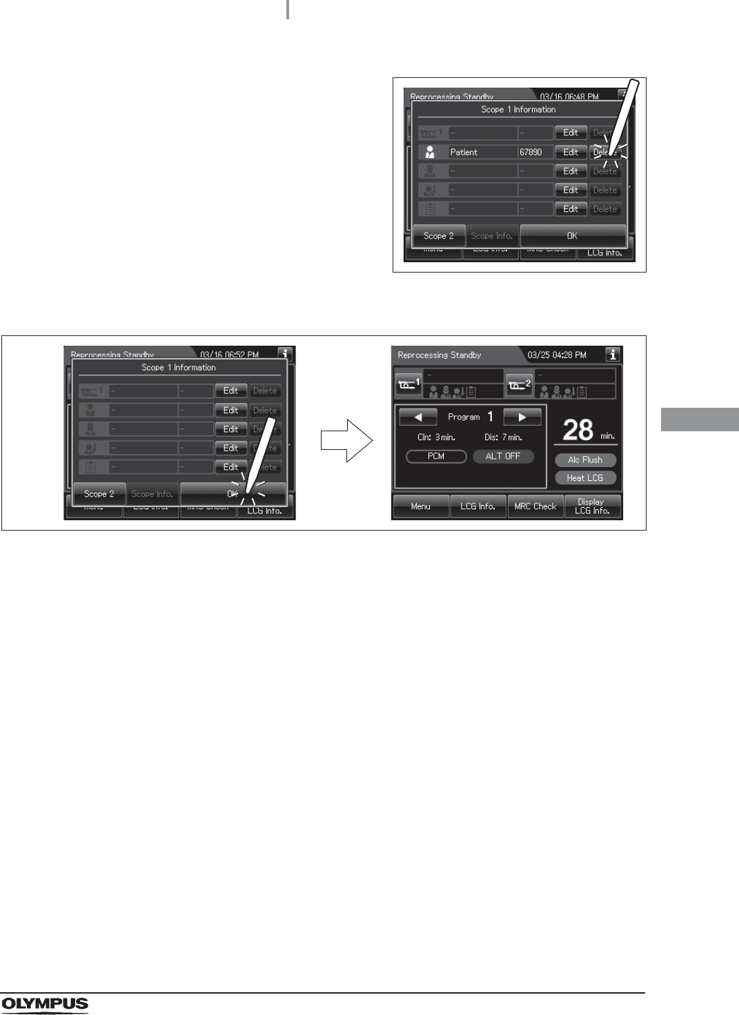
4.23 Checking the operation of optional accessories
185
OER-Elite INSTALLATION MANUAL
Ch.4
5Press the “Delete” button of the patient ID to
delete the patient ID.
Figure 4.233
6Press the “OK” button to return to the reprocessing standby screen.
Figure 4.234
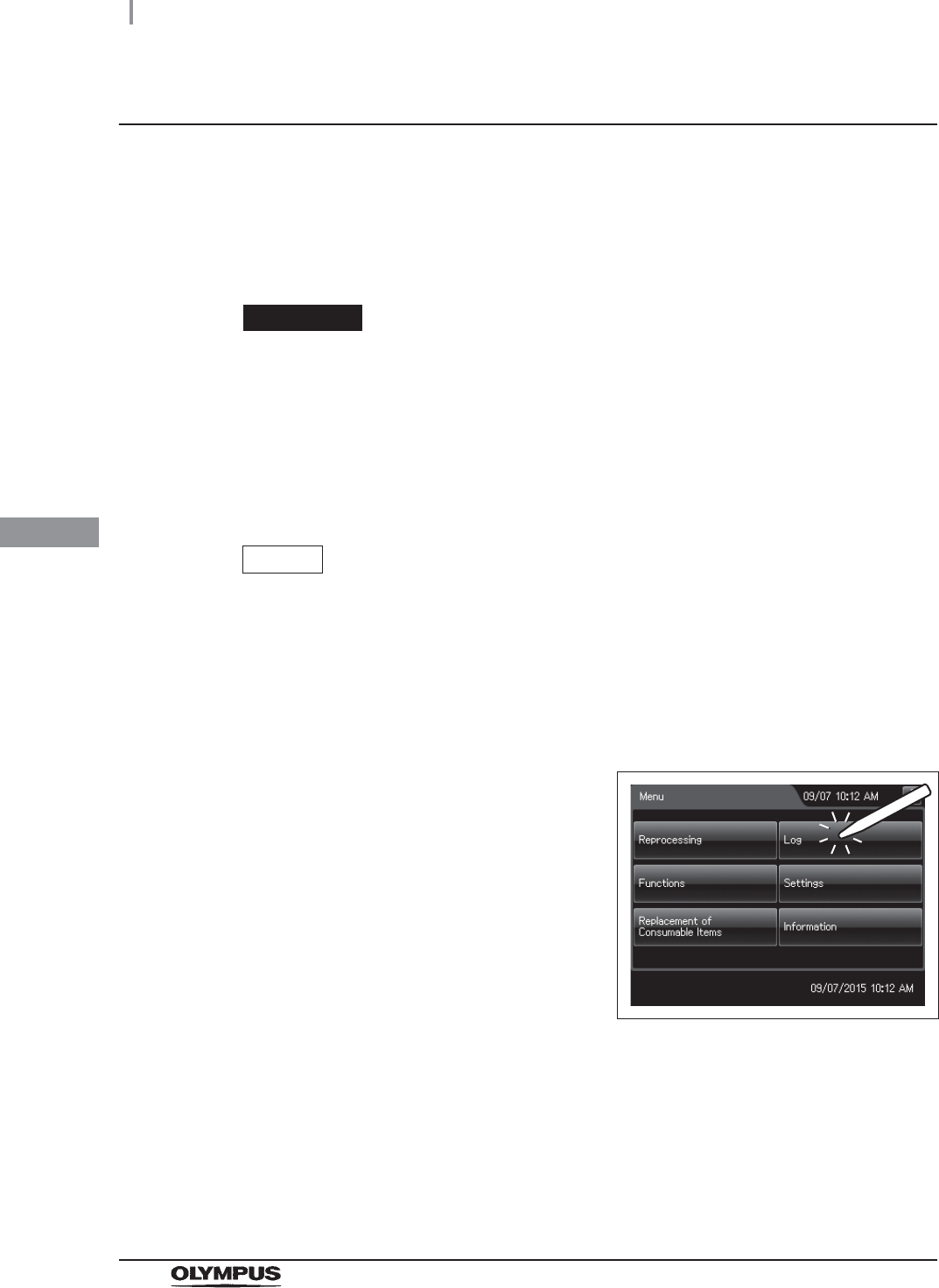
186
4.23 Checking the operation of optional accessories
OER-Elite INSTALLATION MANUAL
Ch.4
Checking the operation of the printer (MAJ-1937)
When the optional printer set MAJ-2144 is installed in the equipment, check the operation of the printer
MAJ-1937 by following procedure.
For the operation of the printer and the set of roll paper, refer to the instruction manual for the printer
set. Make sure that this checking exist record data of reprocessing record, leak test records, or leaking
scope decontamination records.
CAUTION
• Do not connect any other power cord to the printer (MAJ-1937) other than the
power cord which provided with the printer. Connecting any power cord except the
one specified may result in failure or burnout of the equipment.
• Do not connect any cables other than the interface cable of the printer MAJ-1937 to
the printer communication port. Connecting except the specified cable may result in
failure or burnout of the equipment.
NOTE
Make sure that this checking exist record data of reprocessing record, leak test
records, or leaking scope decontamination records. Otherwise, checking cannot
executed. Be sure to execute the reprocessing, leak test, or leaking scope
decontamination.
1Turn on the equipment and the printer MAJ-1937.
2Press the “Log” button on the Menu screen.
Figure 4.235
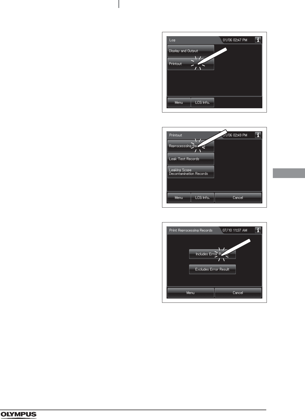
4.23 Checking the operation of optional accessories
187
OER-Elite INSTALLATION MANUAL
Ch.4
3Press the “Printout” button.
Figure 4.236
4Press the “Reprocessing Record” button.
Figure 4.237
5Press the “Include Error Result” button.
Figure 4.238
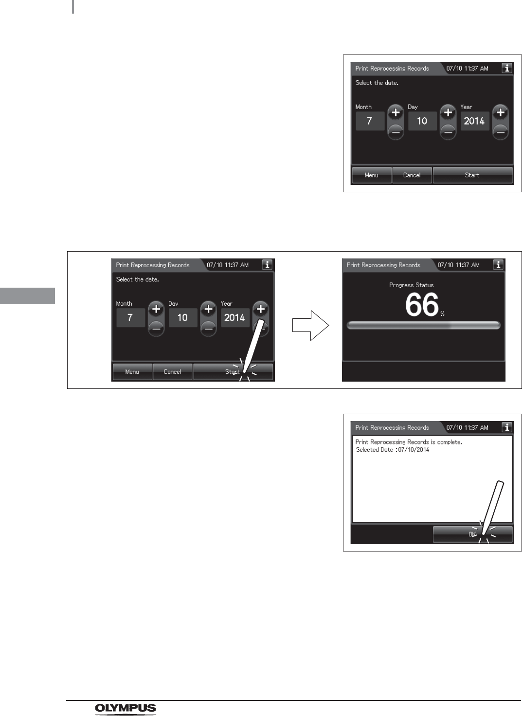
188
4.23 Checking the operation of optional accessories
OER-Elite INSTALLATION MANUAL
Ch.4
6Enter the date of select to be displayed. Press
the “+” button to increase or the “–” button to
decrease.
Figure 4.239
7Press the “Start” button to start printing the reprocessing records. During printing, the
touch screen displays a progress status of printing.
Figure 4.240
8When the screen as shown in Figure 4.241
appears, the printing process is complete.
Press the “OK” button.
Figure 4.241
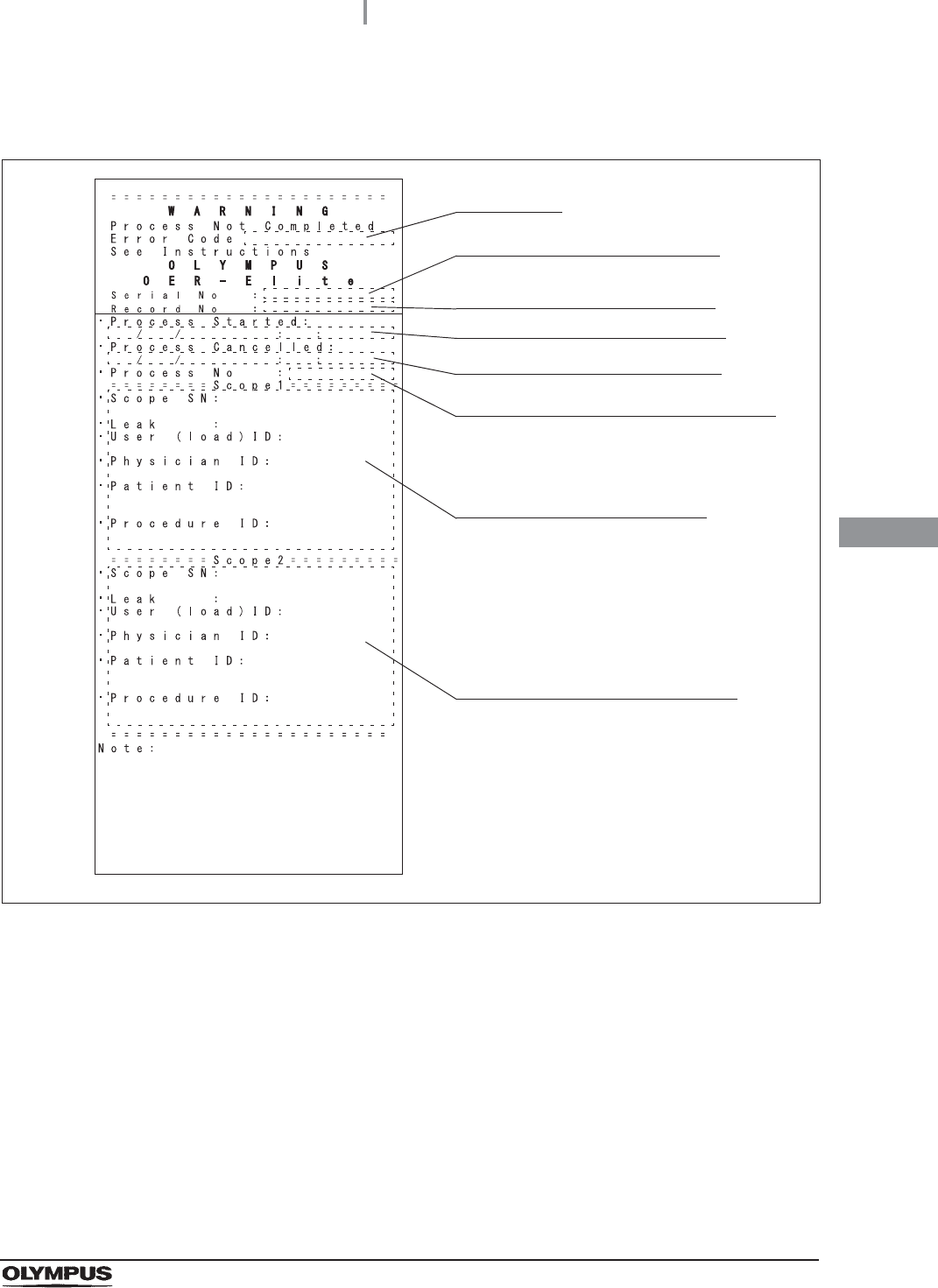
4.23 Checking the operation of optional accessories
189
OER-Elite INSTALLATION MANUAL
Ch.4
9Check that the printed information is correct. If no information is printed, or if the
printed information has errors, reference the instruction manual for the printer set.
Figure 4.242
Serial number of this equipment
Date and time of start of process
Date and time of end of process
Process number of occurrence of error
Information of first endoscope
Error code
Number given to each record in
the order of occurrence
Information of second endoscope

190
4.23 Checking the operation of optional accessories
OER-Elite INSTALLATION MANUAL
Ch.4
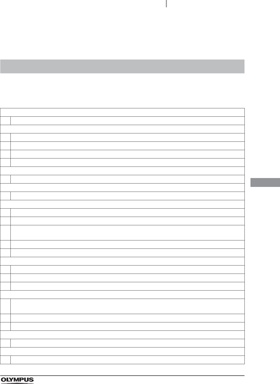
App.
Installation work check points
191
OER-Elite INSTALLATION MANUAL
Installation Work Check Points
To prevent problems due to improper installation, check the following during installation of the
equipment.
Installation work check points
Installation of buckling guard
The provided buckling guard should be attached to the rear of the equipment.
Installation of retaining rack, washing case and drain/circulation port mesh filters
The drain port mesh filter should be installed properly.
The retaining rack should be installed properly.
The washing case should be installed properly.
The two circulation port mesh filters should be installed properly.
Installation of water tray
The water tray should be installed properly.
Installation of stylus pen
The stylus pen holder should be attached to the right side of the equipment.
Connection of water supply hose
Packing should be present inside the water supply plug and the connection ring.
Pull the water supply hose lightly to ensure that there is no loose connection or buckle of the hose.
Tighten the water supply plug and the connection rings on the equipment end of the water supply hose. To
secure the water supply plug, use the provided wrench.
Pull the water faucet end of the water supply hose to ensure that it is not disconnected.
When the water faucet is open, no water should leak from the water supply hose connection area.
Connection of drain hose
The drain hose should not be buckled.
The drain height should be appropriate.
The hose should be cut to an appropriate length.
Connection of power supply
The hospital-grade wall mains mains power outlet should meet the rating (120 V AC/5.5 A) used for the
equipment.
The power cord should be plugged firmly into the equipment and the power outlet.
The power switch should be able to be set to ON.
Installation of equipment
The equipment should be fixed in place by locking the two front casters.
Check for RFID function
The scope IDs should be recognized properly.

App.
192
Installation work check points
OER-Elite INSTALLATION MANUAL
The user IDs should be recognized properly.
The physician IDs should be recognized properly.
Setting of date and time
The built-in clock should be set to the present date and the time.
Installation of gas filters
The gas filters should be installed in the gas filter cases.
The gas filter cases should be present in the two specified positions.
Installation of air filter
The filter should be installed properly.
Installation of water filter
The water filter should be installed with correct (up/down) orientation.
The water filter should be installed properly.
The water filter housing is secured without loosening by the water filter wrench.
No water should leak from the water filter housing.
Air should be drained properly from the water filter housing.
Correction of equipment tilt
The equipment should be level.
Addition of alcohol
70% ethyl alcohol or 70% isopropyl alcohol should be present in the alcohol tank.
Installation of the detergent tank
The detergent tank should be installed on the detergent/alcohol drawer.
The detergent/alcohol inner tray should be installed in position.
Setup of disinfectant solution
Confirm that a buzzer beeps at the end of the supplying process to indicate optimum supplying of disinfectant
solution.
The amount of disinfectant solution should be within the specified range.
Setting of self-disinfection and water sampling
Set the date and time of completion of Self disinfection and water sampling.
Checking Functions
No error code should be displayed.
A jet of fluid should be squirted from the water supply/circulation nozzle to the dome of lid.
Water should not leak from the following positions.
Water supply hose connector
Drain hose connector
Water filter housing and surrounding area
Lid and surrounding area
Lower part of the equipment
Disinfection of the water supply piping
No error code should be displayed.

©2017 OLYMPUS MEDICAL SYSTEMS CORP. All rights reserved.
No part of this publication may be reproduced or distributed without the
express written permission of OLYMPUS MEDICAL SYSTEMS CORP.
OLYMPUS is a registered trademark of OLYMPUS CORPORATION.
Trademarks, product names, logos, or trade names used in this
document are generally registered trademarks or trademarks of each
company.

Printed in Japan 20170303 *0000
GT9883 01
Manufactured by
2951 Ishikawa-cho, Hachioji-shi, Tokyo 192-8507, Japan
Fax: (042)646-2429 Telephone: (042)642-2111
(Premises/Goods delivery) Wendenstrasse 14-18, 20097 Hamburg, Germany
(Letters) Postfach 10 49 08, 20034 Hamburg, Germany
3500 Corporate Parkway, P.O. Box 610, Center Valley, PA
18034-0610, U.S.A.
Fax: (484)896-7128 Telephone: (484)896-5000
KeyMed House, Stock Road, Southend-on-Sea, Essex SS2 5QH, United Kingdom
Fax: (01702)465677 Telephone: (01702)616333
491B, River Valley Road #12-01/04, Valley Point Office Tower, Singapore 248373
Fax: 6834-2438 Telephone: 6834-0010
A8F, Ping An International Financial Center, No. 1-3, Xinyuan South Road,
Chaoyang District, Beijing, 100027 P.R.C.
Fax: (86)10-5976-1299 Telephone: (86)10-5819-9000
Elektrozavodskaya str. 27 bld.8, 107023 Moscow, Russia
Fax: (7)495-663-8486 Telephone: (7)495-926-7077
3 Acacia Place, Notting Hill, VIC 3168, Australia
Fax: (03)9543-1350 Telephone: (03)9265-5400
5301 Blue Lagoon Drive, Suite 290 Miami, FL 33126-2097, U.S.A.
Fax: (305)261-4421 Telephone: (305)266-2332
Distributed by
Olympus Tower 9F, 446, Bongeunsa-ro, Gangnam-gu, Seoul, Korea 135-509
Fax: (02)6255-3494 Telephone: (02)6255-3210
Fax: (040)23773-4656 Telephone: (040)23773-0