Olympus Medical Systems RU2020 Endoscope Reprocessor User Manual GT9882 0100 fm10
Olympus Medical Systems Corp. Endoscope Reprocessor GT9882 0100 fm10
Contents
Operation Manual 2
5.3 Inspecting the power activation
129
OER-Elite OPERATION MANUAL
Ch.5
Check that the reprocessor can be turned ON.
8Check that the mesh filters are not clogged.
Section 5.10 on page 143
9Check that the cleaning case is free of abnormality.
Section 5.11 on page 144
10 Check that the labels on the reprocessing basin are not peeled.
Section 5.12 on page 145
11 Check that the disinfectant vapor is not abnormal.
Section 5.13 on page 145
5.3 Inspecting the power activation
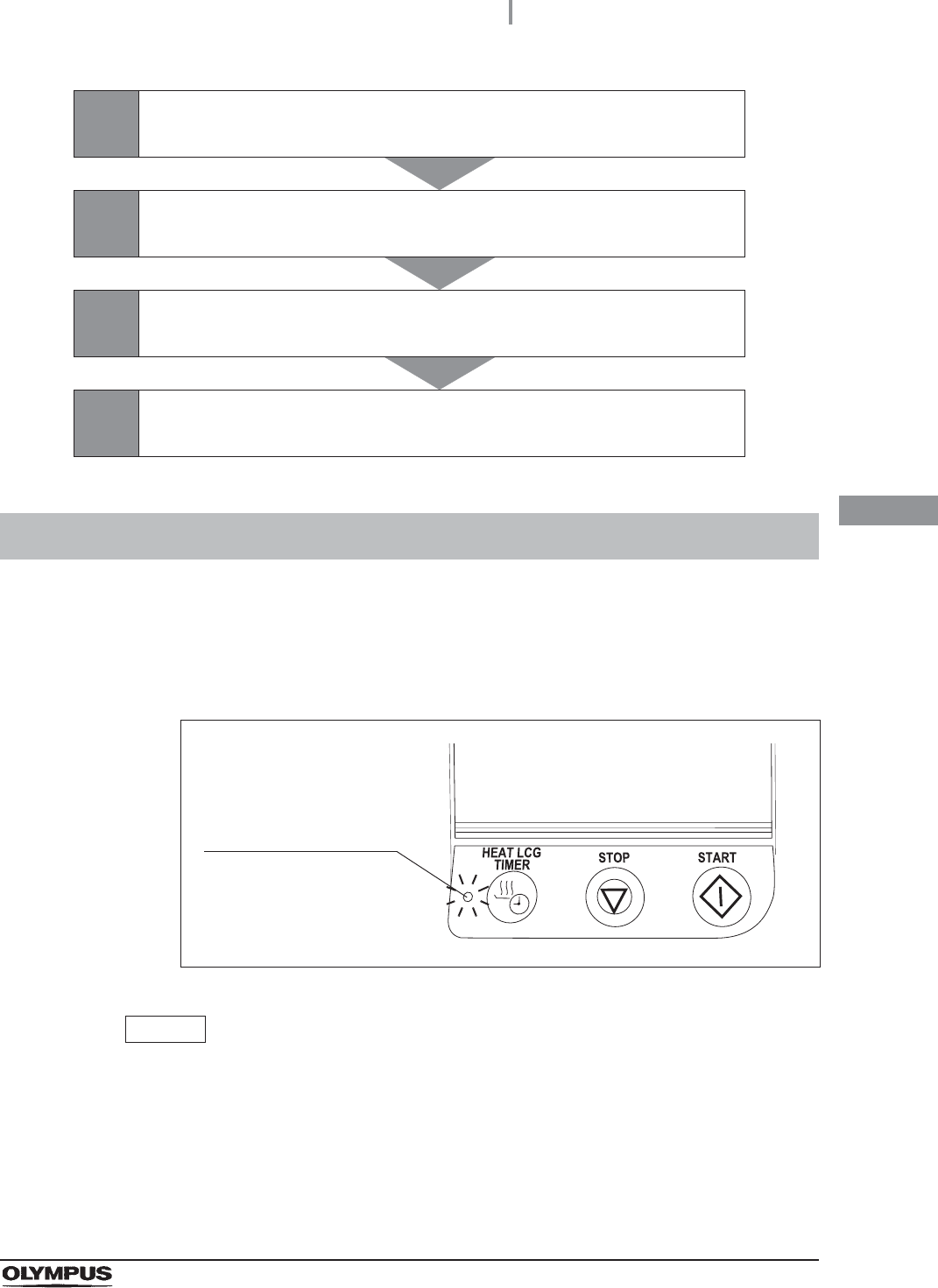
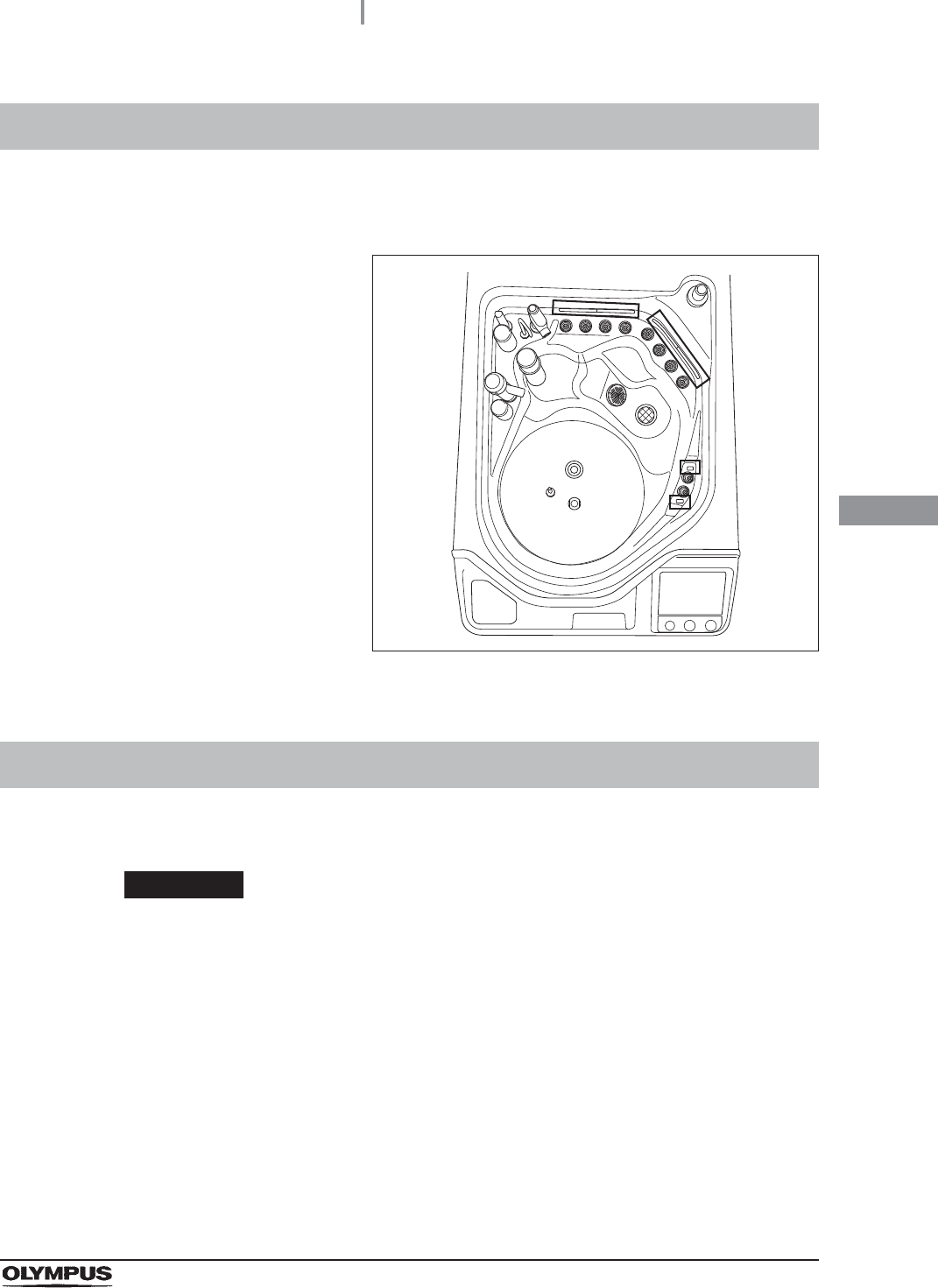
1Make sure that the disinfectant solution Heat LCG Timer indicator is not illuminated. If
it is lighting up, it is not necessary to inspect the reprocessor power switch again.
Figure 5.1
NOTE
The lighting of the disinfectant solution Heat LCG Timer indicator indicates that the
disinfectant solution Heat LCG Timer is running. For operation of the disinfectant
solution Heat LCG Timer process, refer to Section 7.3, “Heat LCG Timer”.
Disinfectant solution
Heat LCG Timer
indicator
130
5.3 Inspecting the power activation
OER-Elite OPERATION MANUAL
Ch.5
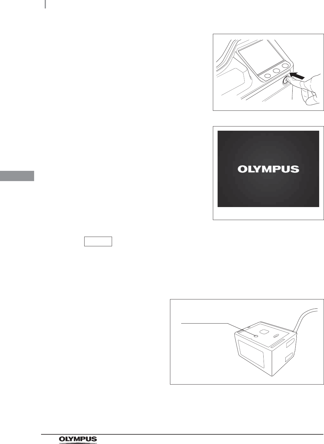
2When the disinfectant solution Heat LCG Timer
indicator does not light up, press the power
switch of the reprocessor.
Figure 5.2
3Make sure that the power indicator lights up
and the touch screen displays the following
initial screen.
Figure 5.3
NOTE
When the optional bar code reader MAJ-2130 is connected to the reprocessor and
the MAJ-2130 is turned ON, the indicator of the bar code reader will light up
alternating red and blue. If the indicator of the bar code reader is not lit, refer to the
instruction manual for bar code reader MAJ-2130 and Section 13.2,
“Troubleshooting guide”.
Figure 5.4
Initial screen
Indicator lights up
alternately red
and blue.
5.3 Inspecting the power activation
131
OER-Elite OPERATION MANUAL
Ch.5
If either the touch screen is blanking or the power indicator does
not light up
If the initial screen does not appear on the touch screen or the power indicator does not light up,
turn the printer OFF by pressing the power switch, wait for a few seconds and press the power
switch to ON again. If the problem is not corrected, press the power switch to OFF again, unplug
the power cord from the power outlet and contact Olympus.
If the touch screen is blank and the power indicator does not
light up
If the initial screen does not appear on the touch screen and the power indicator does not light
up, inspect the reprocessor in the procedure described in Section 9.8, “Replacing the fuse”. If
the problem is not corrected, press the power switch to OFF again, unplug the power cord from
the power outlet and contact Olympus.
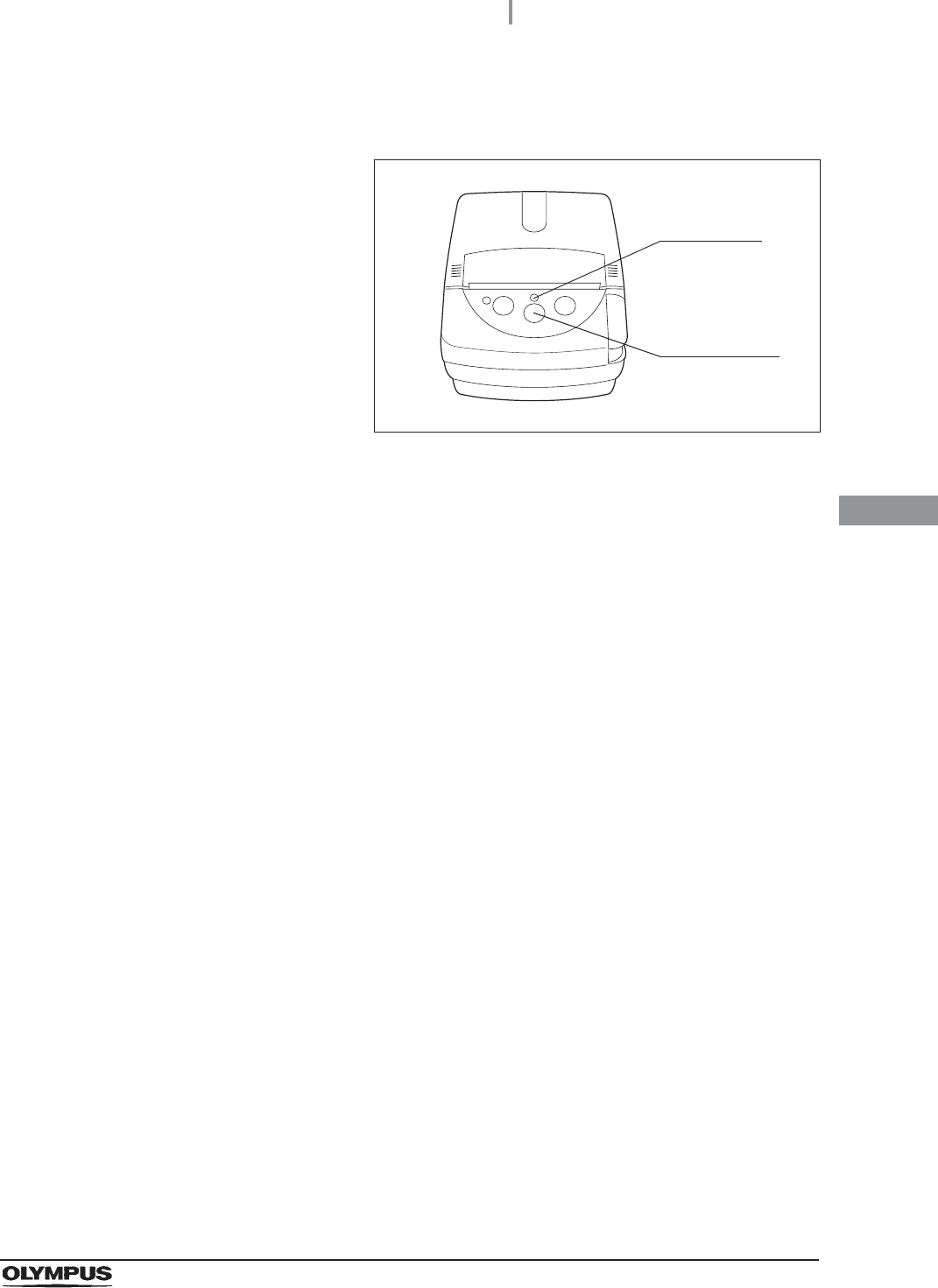
4When the optional printer MAJ-1937 is connected to the reprocessor, press the power
button of the printer until the power LED turns ON (about 1 second).
Figure 5.5
Power LED
Power button

132
5.4 Inspecting for fluid leaks
OER-Elite OPERATION MANUAL
Ch.5
Confirm that water or fluid does not leak from the water supply piping, inside the reprocessor, drain
hose connector, etc.
WARNING
• Do not continue using the reprocessor if it is leaking water. Doing so may result in
an electric shock or malfunction.
• If water or fluid leaks from inside the reprocessor, close the water faucet, set the
power switch to OFF, unplug the power cord, and contact Olympus.
If water leaks from the water supply hose connector
If water leaks from the water filter housing
If water or fluid leaks from inside the reprocessor
5.4 Inspecting for fluid leaks
1Slowly open the water faucet.
2Confirm that water is not leaking from where the water supply hose is connected to
the water faucet or reprocessor.
3Confirm there is no water or fluid on the floor underneath the reprocessor.
1Close the water faucet.
2Check the loading of the water supply devices by referring to Section 4.4, “Connection
of the water supply hose” in “Instructions-Installation Manual”.
1Close the water faucet.
2Check the loading of the water filter housing by referring to Section 4.14, “Installation
of the water filter (MAJ-824 or MAJ-2318)” in “Instructions-Installation Manual”.
1Close the water faucet.
2Set the power switch of the reprocessor to OFF.
3Unplug the power cord from the power outlet.
4Contact Olympus.
5.5 Inspecting the lid and lid packing
133
OER-Elite OPERATION MANUAL
Ch.5
If water leaks from the drain hose connector
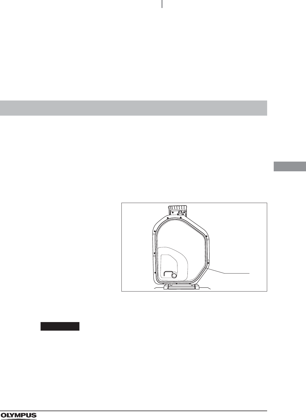
Before using the reprocessor, always check that there is no irregularity regarding the following points
on the lid and the lid packing. If there is any irregularity, cleaning fluid or disinfectant solution may leak
out.
• The lid is not cracked, broken, or otherwise damaged.
• The packing is not cracked, torn, or otherwise damaged.
• The packing is not separated or detached from the lid.
• The lid can be properly opened and closed without restriction or abnormal noise.
Figure 5.6
If any irregularity is found, do not use the reprocessor and contact Olympus.
WARNING
• Do not use the reprocessor if the lid or the lid packing seems to be damaged or
defective. Using the reprocessor when an irregularity has been detected may
interfere with reprocessing. Furthermore, fluid leakage may damage peripheral
devices or facilities near the equipment. If any irregularity is found with the lid or the
lid packing, contact Olympus.
• Do not remove the lid packing. Otherwise, disinfectant solution may leak and
damage for the reprocessor and areas near the equipment by reprocessing or
opening the lid.
1Close the water faucet.
2Check the drain hose loading by referring to Section 4.5, “Connection of the drain
hose” in “Instructions-Installation Manual”.
5.5 Inspecting the lid and lid packing
Packing

134
5.6 Inspecting the connectors
OER-Elite OPERATION MANUAL
Ch.5
WARNING
• If replacement or adjustment of the lid packing is required, please contact Olympus.
Only Olympus-trained personnel are permitted to replace the lid packing or adjust
its position. Improper installation or positioning of the lid packing may result in
leakage of water, detergent solution, or disinfectant solution. This may result in
injury to personnel and/or damage to the equipment.
Check the following for each connector.
The connector should be fixed firmly.
The O-rings should be free of irregularities such as cracks, tears, or dents.
If any irregularity is found, do not use the reprocessor and contact Olympus.
WARNING
Do not use the reprocessor if any connector seems to be damaged or defective.
Using the reprocessor when an irregularity has been detected may interfere with
reprocessing. Furthermore, fluid leakage may damage peripheral devices or
facilities near the equipment.
CAUTION
Connect each connector firmly by pushing until the connector clicks into place.
After connection, pull the connector gently to confirm that it cannot be disconnected
easily.
NOTE
After long-term using the OER-Elite, the color of O-rings on each connector may be
changed into whitish color. This case is not irregularity.
5.6 Inspecting the connectors
5.6 Inspecting the connectors
135
OER-Elite OPERATION MANUAL
Ch.5
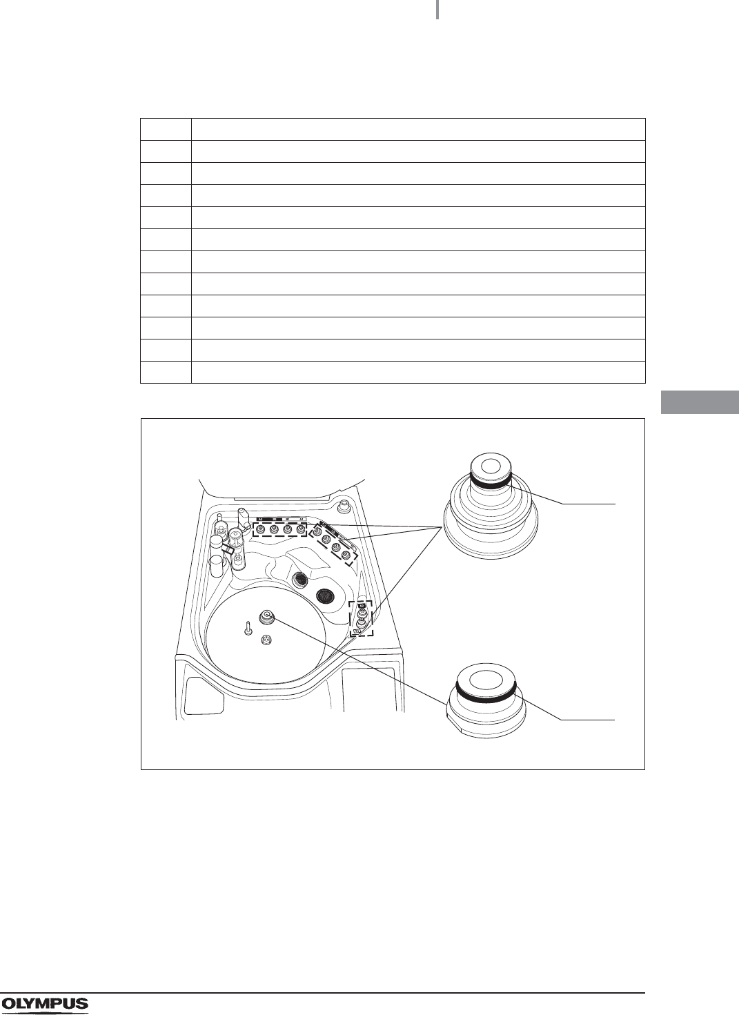
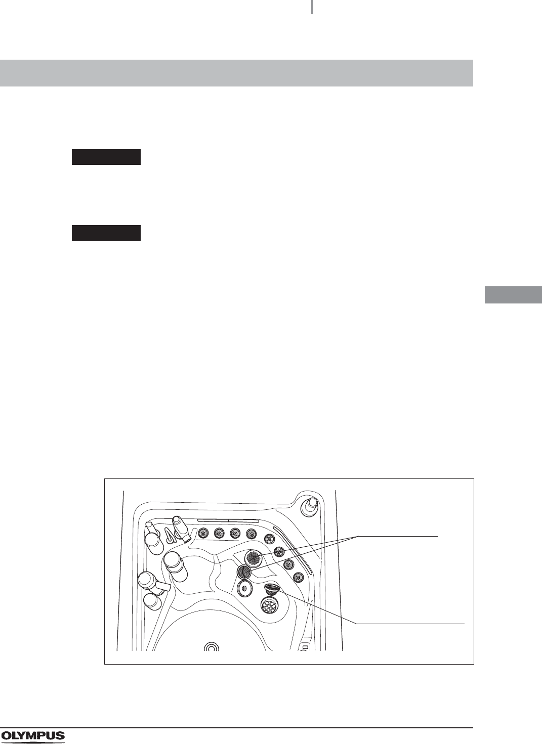
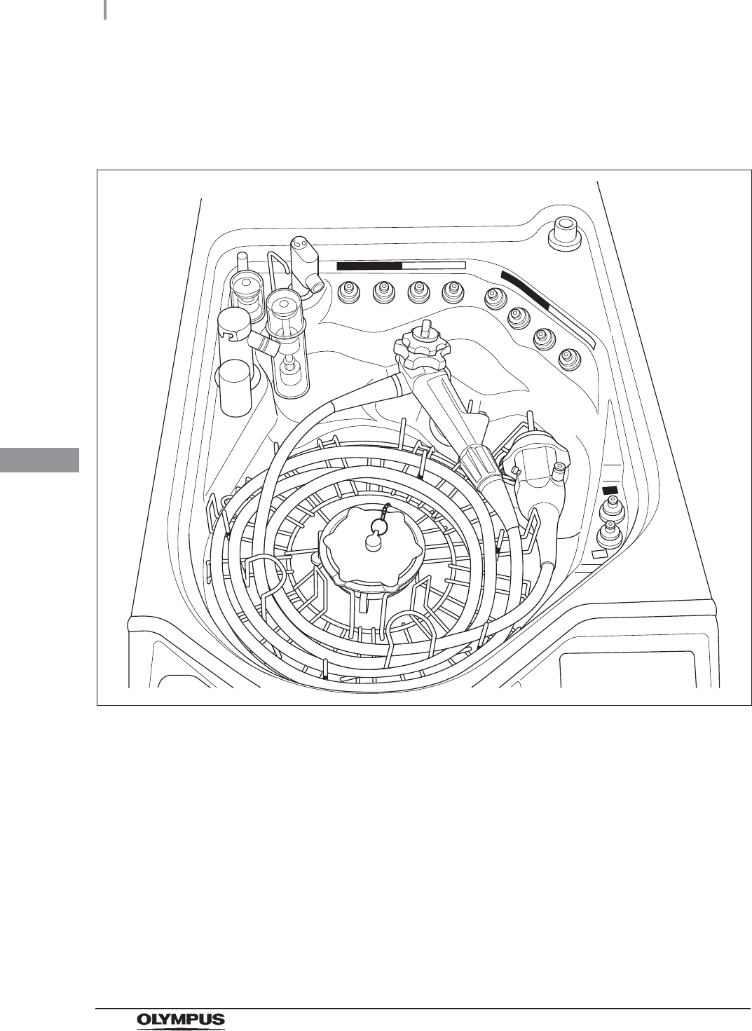
Connectors inside the reprocessing basin:
Table 5 . 1
Figure 5.7
Check Connectors inside the reprocessing basin:
Connector A1
Connector A2
Connector B1
Connector B2
Connector C1
Connector C2
Connector D1
Connector D2
Connector E1
Connector E2
Water supply piping disinfection connector
O-ring
O-ring
136
5.6 Inspecting the connectors
OER-Elite OPERATION MANUAL
Ch.5
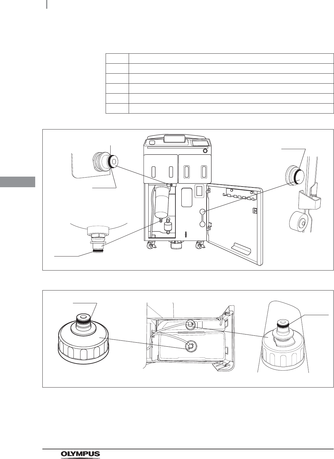
Other connectors
Table 5.2
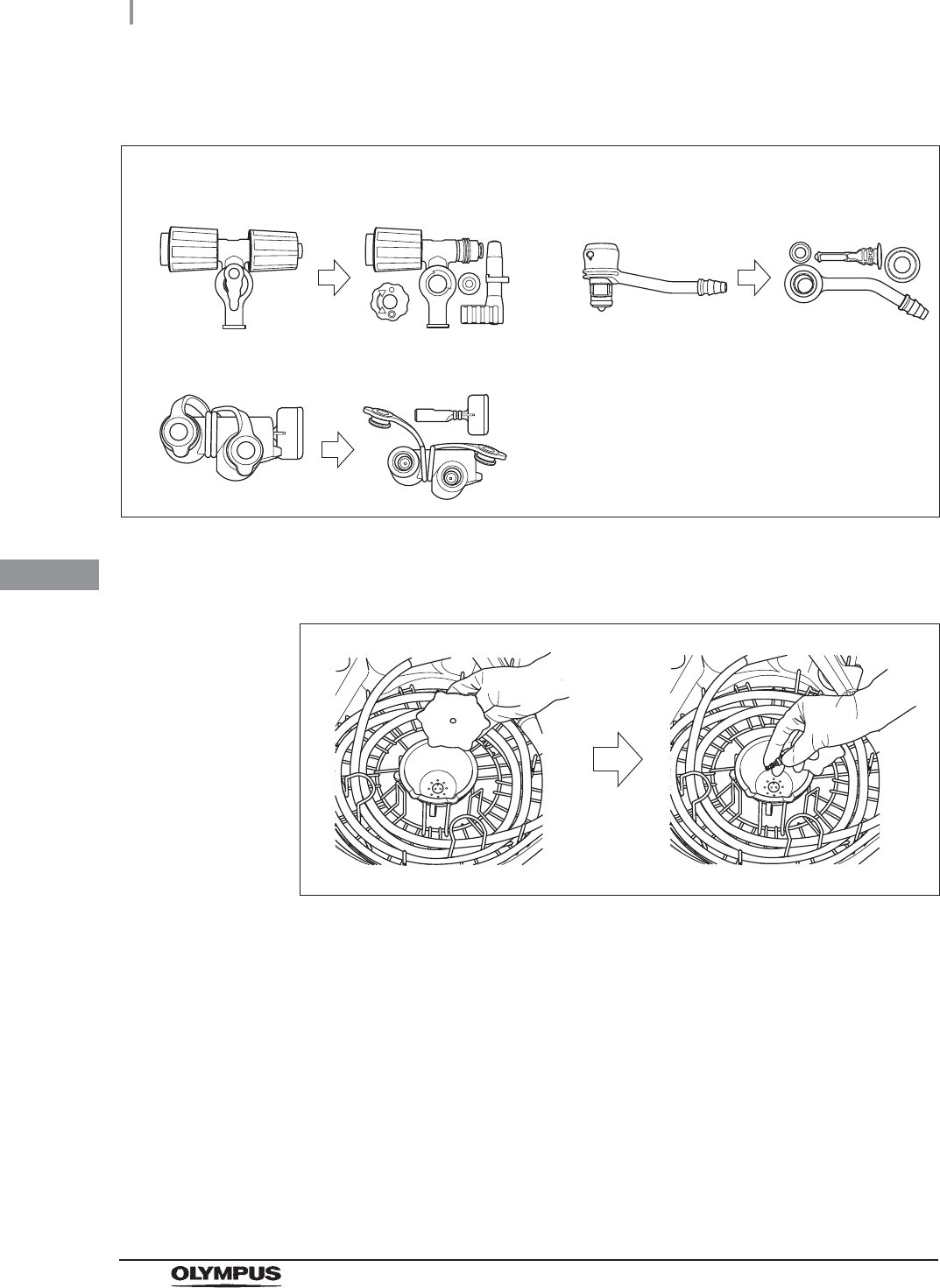
Figure 5.8
Figure 5.9
Check Other connectors
Connector above water filter housing
Connector below water filter housing
Disinfectant removal port
Tube connector on detergent tank
Tube connector on alcohol tank
O-ring
O-ring
O-ring
O-ring
O-ring
5.7 Inspecting the connecting tubes and leak test air tube
137
OER-Elite OPERATION MANUAL
Ch.5
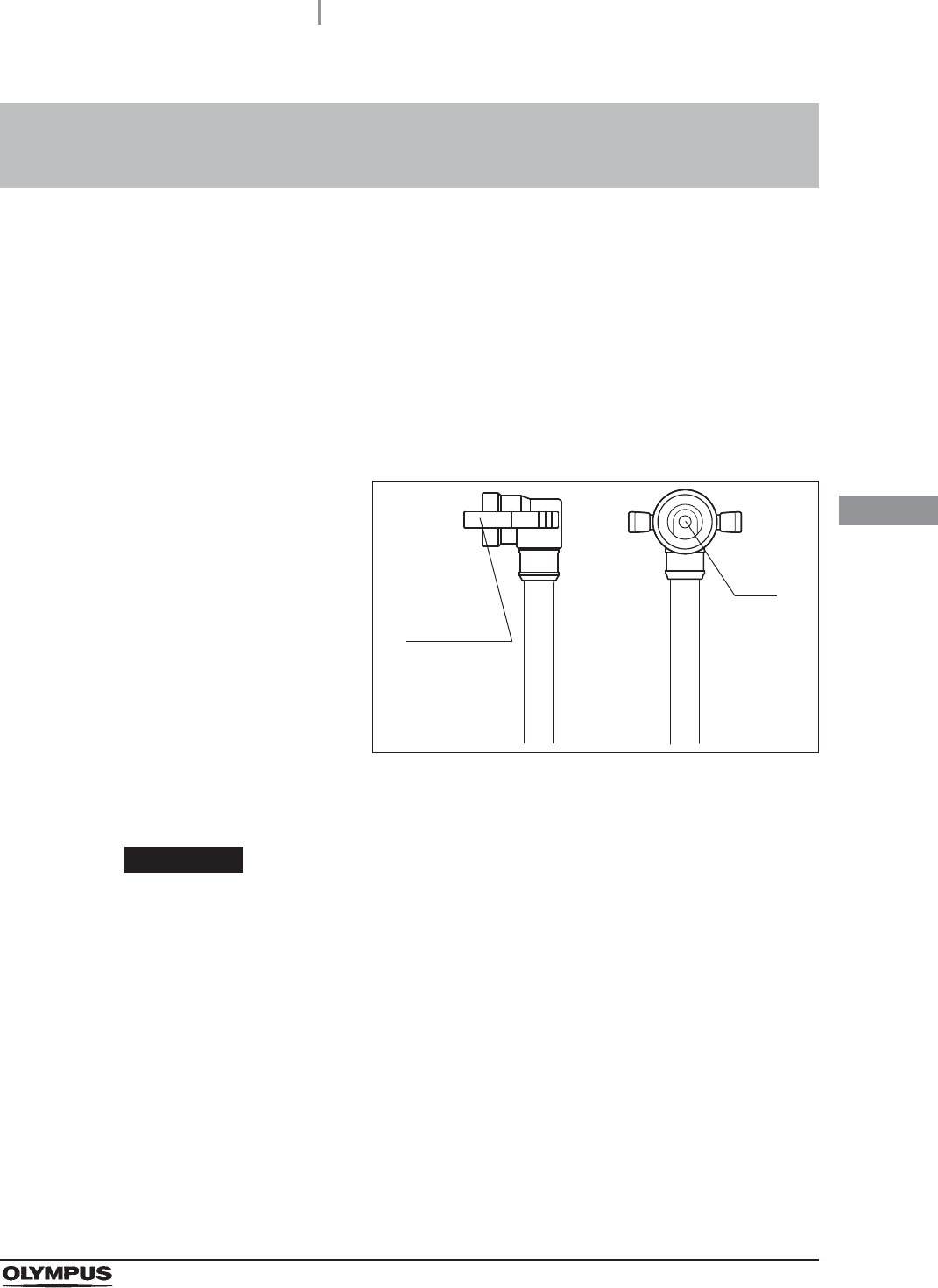
Before using the reprocessor, always check that there is no irregularity regarding the following points
on the connecting tubes and leak test air tube.
All tubes should be free of cracks, breaks, fissures, scratches, or stains.
There should be no cracks in the lock levers of connecting tube connectors and leak test
air tube connectors.
There should be no bends or breaks in the pin of connecting tubes connector and leak test
air tube connector.
The tube should not be easy to disconnect once connected.
Figure 5.10
If a tube has any irregularity, do not use it and replace with a new one.
WARNING
Do not use the connecting tubes or leak test air tubes if they have any irregularity.
Doing so could prevent effective reprocessing or damage the endoscope.
5.7 Inspecting the connecting tubes and leak test air
tube
Lock lever
Pin
138
5.8 Inspecting the remaining detergent
OER-Elite OPERATION MANUAL
Ch.5
Table 5.3
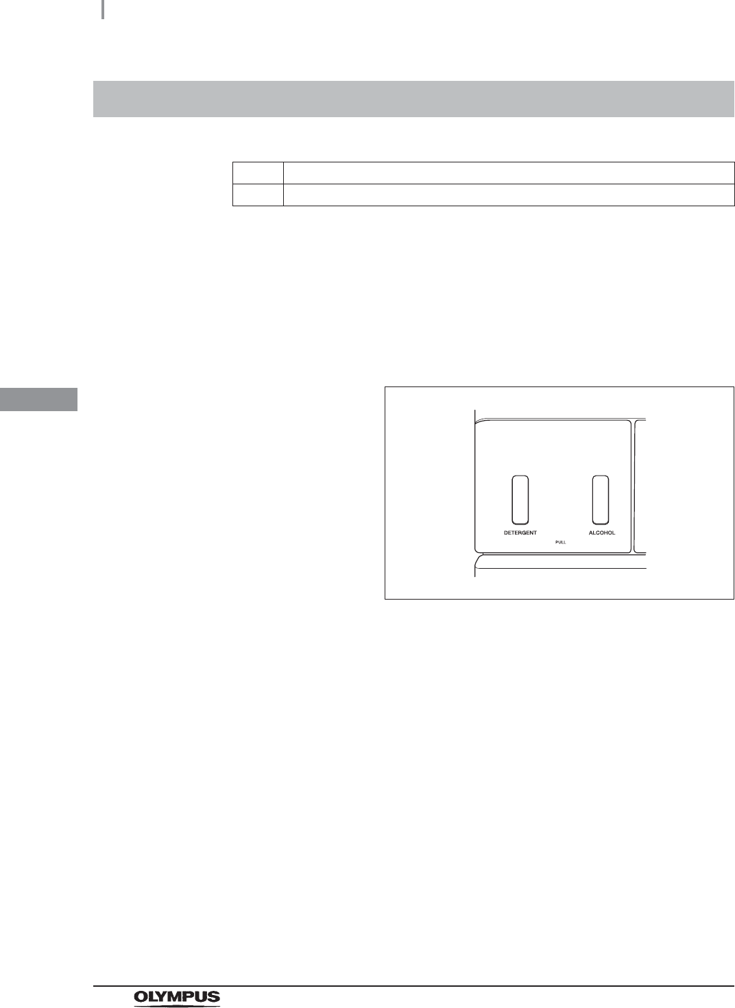
Check the amount of detergent remaining in the detergent tank through the detergent tank check
window on the detergent/alcohol drawer of the reprocessor. If the detergent level cannot be viewed
from the window, the detergent in the detergent tank should be replaced after executing the
reprocessing process for a few times. When the detergent level is not visible through the window or the
touch screen shows the detergent supply insufficiency message (together with the detergent
replacement indicator) after the start of a process, replace the detergent tank as described in
Section 8.3, “Replacing the detergent tank”.
Figure 5.11
5.8 Inspecting the remaining detergent
Check Required items
Olympus-validated detergent
5.9 Inspecting and replenishing alcohol
139
OER-Elite OPERATION MANUAL
Ch.5
Check how much alcohol is in the alcohol tank and add more as required.
Table 5 . 4
WARNING
• The alcohol used with the reprocessor must be 70% ethyl alcohol or 70% isopropyl
alcohol. Using any other kind of alcohol may result in malfunction of the
reprocessor or the endoscope, difficulty drying the endoscope, fire hazard, or a
hazard due to toxic vapor emitted from the alcohol.
• Alcohol is flammable and should be handled with extra care.
• Remove the alcohol in the alcohol tank and replace it with new alcohol at least once
a week. Otherwise, the alcohol in the alcohol tank may degrade.
• Before handling the alcohol, carefully read the cautions for use carefully, and use
the alcohol as instructed.
NOTE
• If alcohol flush is initiated without alcohol in the tank, the message screen “Alcohol
cannot be supplied” will be displayed and the process will be stopped temporality.
• When reprocessing is performed with newly-installed equipment or with
reprocessor after Section 9.9, “Preparing the reprocessor for long-term storage” is
performed, reprocessing may stop with the message screen “Alcohol cannot be
supplied during the process” displayed even though there is enough alcohol in the
tank. Refer to “When the message screen “Message 087” is displayed” on
page 627 to solve this problem.
5.9 Inspecting and replenishing alcohol
Check Required items
70% ethyl alcohol or 70% isopropyl alcohol
140
5.9 Inspecting and replenishing alcohol
OER-Elite OPERATION MANUAL
Ch.5
Inspection of the amount of alcohol
Ensure that the alcohol is present through the alcohol tank check window on the detergent/alcohol
drawer of the reprocessor. If the alcohol level cannot be viewed from the window, the alcohol in the
alcohol tank should be replaced after executing the reprocessing process for a few times. When the
alcohol level becomes invisible through the window, replenish the alcohol as described in
“Replenishing of alcohol” below.
NOTE
If alcohol flush is performed without alcohol, the touch screen shows the Alcohol
supply insufficiency message and the flushing pauses.
Replenishing of alcohol
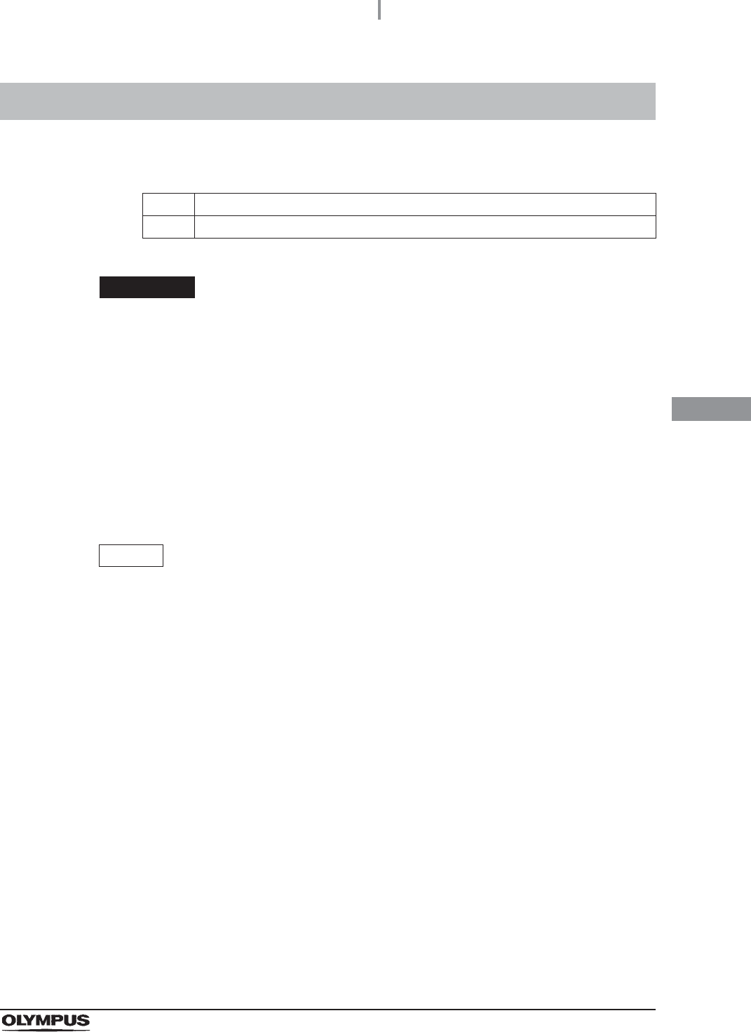
1Hold the section on the detergent/alcohol
drawer marked “PULL” and pull it out.
Figure 5.12
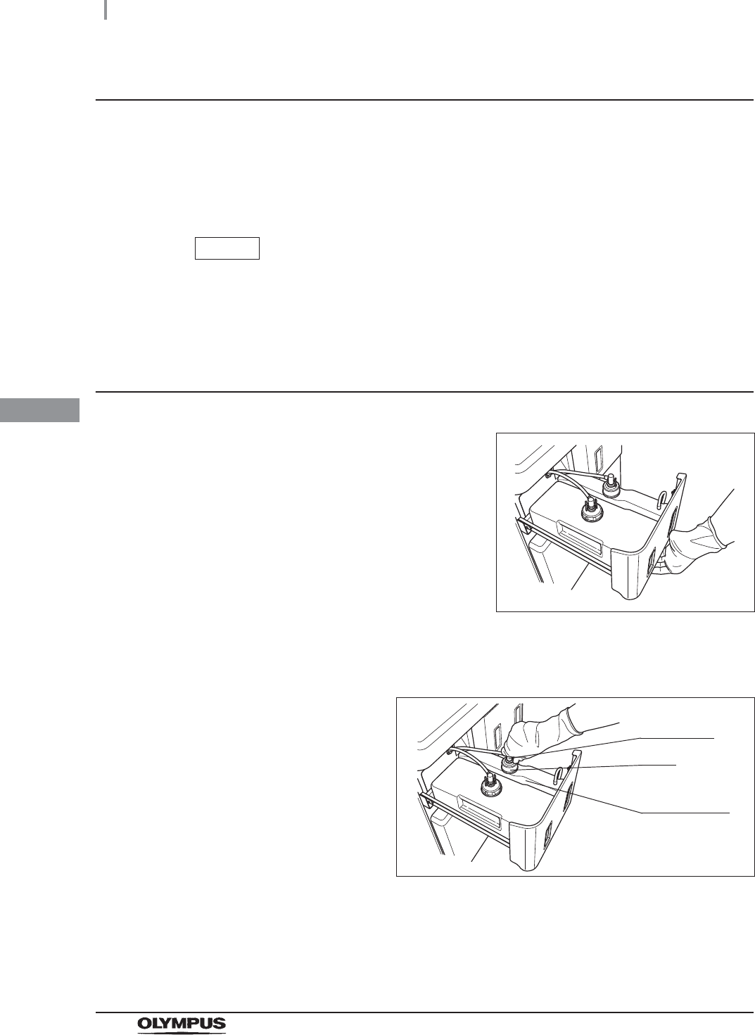
2Push the lock lever on the connector of the tube connected to the cap on the alcohol
tank to detach the tube.
Figure 5.13
3Remove the alcohol tank and put it in a sink or other tub.
Alcohol tank
Cap
Lock lever
5.9 Inspecting and replenishing alcohol
141
OER-Elite OPERATION MANUAL
Ch.5
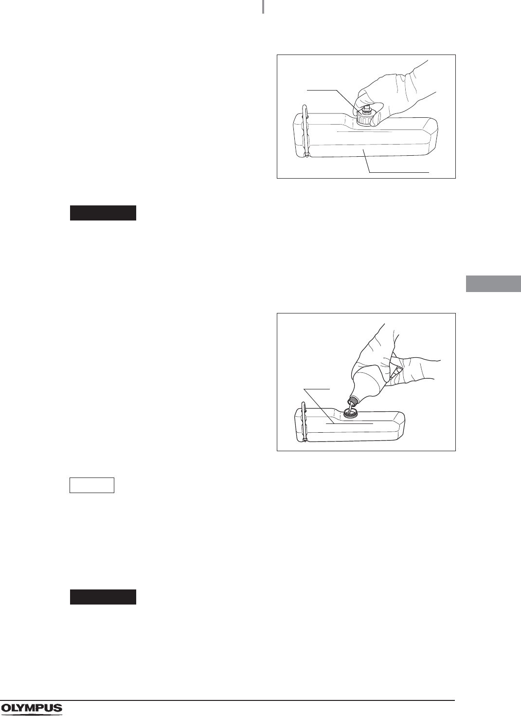
4Turn the cap on the alcohol inlet in the direction
shown to remove the cap.
Figure 5.14
CAUTION
• Do not add alcohol while the tank is in the detergent/alcohol drawer. If alcohol is
spilled on the tray, it could damage the reprocessor.
• Do not tilt the alcohol tank while there is still alcohol inside. Otherwise, the alcohol
may spill.
5Pour alcohol until it is level with the line inside
the alcohol tank. Do not to spill any. If any
alcohol spills from the tank, wipe it off with a
clean cloth. After adding the alcohol, replace
the cap on the alcohol tank.
Figure 5.15
NOTE
The amount of alcohol required to fill the tank up to the level line is about 1 L
(enough for about 20 alcohol flushes).
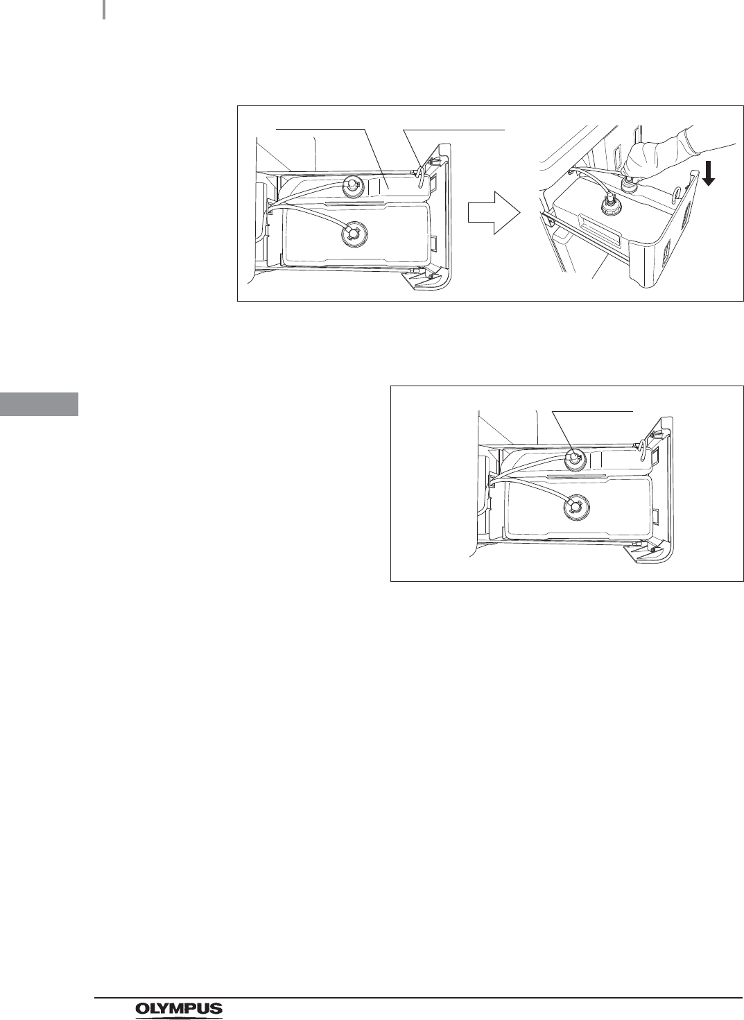
6Place the alcohol tank in the detergent/alcohol drawer so that the ventilation tube of
the alcohol tank sits on the front of the tray.
CAUTION
Placing the alcohol tank so that the ventilation tube sits on the deeper side of the
tray could damage the alcohol tank.
Alcohol inlet
Cap
Line
142
5.9 Inspecting and replenishing alcohol
OER-Elite OPERATION MANUAL
Ch.5
7Connect the tube that was originally connected to the cap.
Figure 5.16
8Turn the connector to correct the tube orientation as shown below. Confirm that the
tube is not bent.
Figure 5.17
9Close the detergent/alcohol drawer.
Alcohol tank Ventilation tube
Connector
5.10 Inspecting the mesh filters
143
OER-Elite OPERATION MANUAL
Ch.5
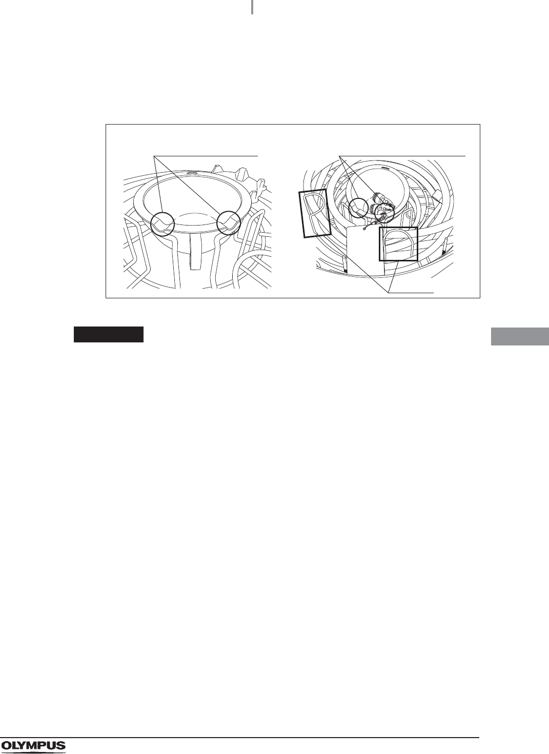
Make sure that the circulation port mesh filters (two types) and the drain port mesh filter are not
clogged.
WARNING
A clogged mesh filter not only prevents the reprocessor from functioning properly,
but may also result in ineffective reprocessing.
CAUTION
• If the mesh filters have been removed, be sure to put them back in their original
positions before using the reprocessor. If you forget to attach the mesh filters, the
pump may malfunction and/or foreign objects may clog the endoscope channels
including the nozzle.
• When cleaning the mesh filters, take care not to leave brush hair or cotton swab
fiber in the meshes. Otherwise, their filtering effectiveness may be reduced.
• If a mesh filter is dropped or subjected to an impact, make sure that the mesh
shape is not deformed. Otherwise, the filtering effect may degrade.
• Two-type mesh filters are installed on the outer and inner sides of the circulation
port. Be sure to remove, inspect, and clean both of them.
5.10 Inspecting the mesh filters
1Step on the foot pedal to open the lid.
2Remove the mesh filters from the reprocessing basin.
Figure 5.18
3Check that the mesh filters are not clogged by a foreign object.
Drain port mesh filter
Circulation port
mesh filters
144
5.11 Inspecting the washing case (MAJ-2121)
OER-Elite OPERATION MANUAL
Ch.5
Make sure that the washing case (with a gray cover) for exclusive use with this reprocessor is
attached. Also, check that the washing case is free of irregularity such as a crack or fissure. If any
irregularity is found, do not use the washing case and contact Olympus.
WARNING
• Do not use the washing case if any irregularity is found with it. If an abnormal
washing case is used, the reprocessing may be insufficient.
• Make sure that the washing case is located in correct position. Otherwise, the
reprocessing may be insufficient.
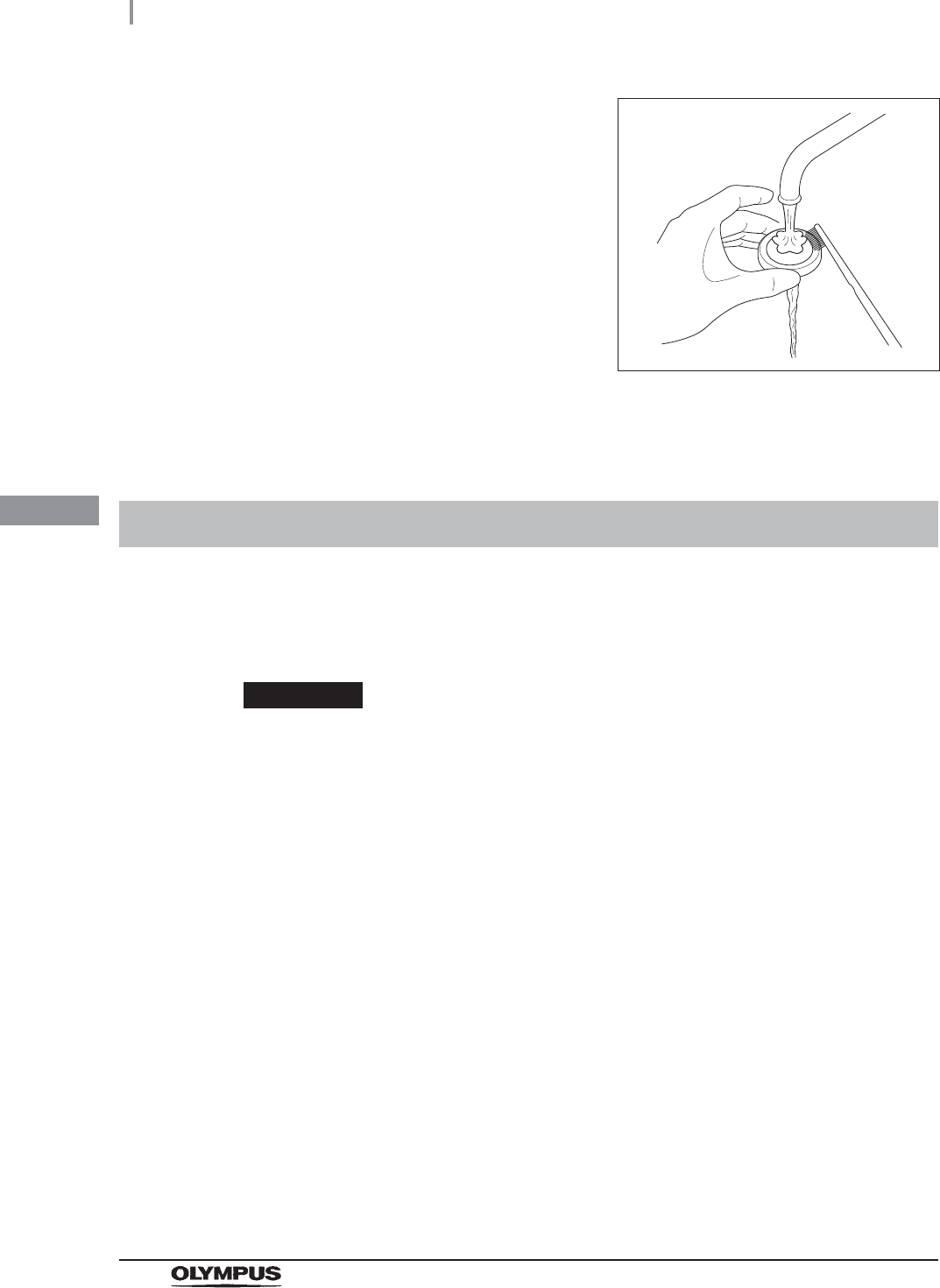
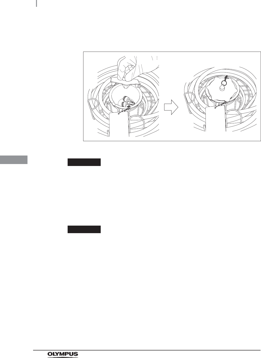
4If any foreign object is found to be clogging the
filter, clean the mesh filter in running water
using a brush.
Figure 5.19
5Attach the mesh filters in their original positions.
5.11 Inspecting the washing case (MAJ-2121)
5.12 Inspecting the labels on the reprocessing basin
145
OER-Elite OPERATION MANUAL
Ch.5
Check that the labels on the reprocessing basin are not peeled off.
If a label is peeled off, contact Olympus.
Figure 5.20
Check that the disinfectant solution is not producing an abnormal odor.
CAUTION
If the odor increases after replacement of the gas filters, contact Olympus.
5.12 Inspecting the labels on the reprocessing basin
5.13 Inspecting for disinfectant solution odor
1Check that the gas filter is placed properly in the gas filter case (tank).
2Check that the gas filter case (tank) is attached properly to the disinfectant solution
tank.
3Activate the room’s ventilation system.
4Check that there is no abnormal disinfectant solution odor coming from the
reprocessor or its surroundings.

146
5.13 Inspecting for disinfectant solution odor
OER-Elite OPERATION MANUAL
Ch.5
6.1 General flow of endoscope reprocessing using OER-Elite
147
OER-Elite OPERATION MANUAL
Ch.6
Chapter 6 Reprocessing Operations
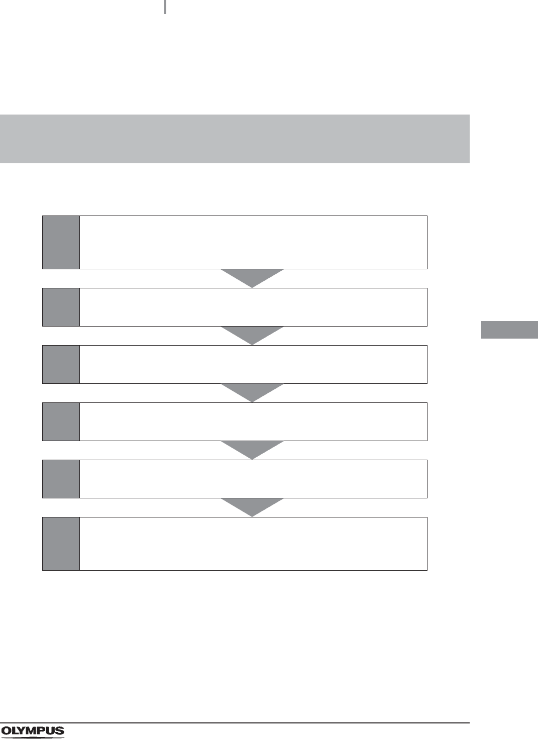
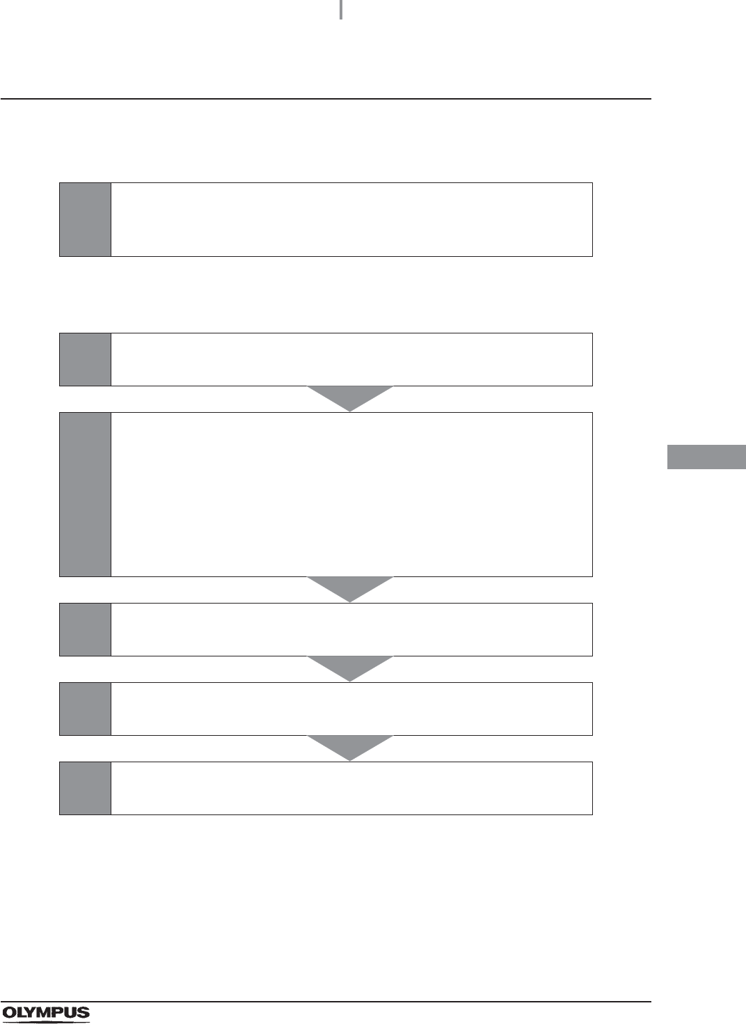
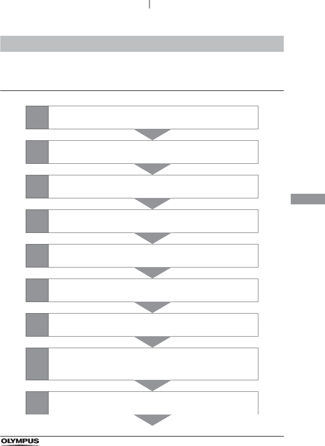
The endoscope reprocessing using OER-Elite is performed in the following flow.
6.1 General flow of endoscope reprocessing using
OER-Elite
1
Patient procedure.
Refer to reprocessing instructions
provided in the endoscope manual
2Precleaning.
Section 6.2 on page 148
3Leak testing.
Section 6.2 on page 148
4Manual cleaning.
Section 6.2 on page 148
5Reprocessing operation in the OER-Elite.
Section 6.3 on page 155
6
Storing the reprocessed endoscope and accessories.
Refer to reprocessing instructions
provided in the endoscope manual

148
6.2 Precleaning, leak testing, and manual cleaning
OER-Elite OPERATION MANUAL
Ch.6
Endoscopes must be first cleaned according to one of two ways, prior to reprocessing in the
OER-Elite:
Precleaning and manual cleaning
Immediately after each patient examination, perform bedside precleaning, clean the outer
surfaces of the endoscope, brush the suction channel, flush and rinse all channels according to
the step-by-step cleaning procedure described in the endoscope’s reprocessing manual.
Complete both the prescribed bedside and manual cleaning procedures. After the endoscope
undergoes full manual cleaning, it can be reprocessed in the OER-Elite. The OER-Elite then
provides supplemental cleaning and high-level disinfection.
Modified precleaning and manual cleaning
Immediately after each patient examination, perform the bedside-precleaning and
manual-cleaning procedures for the endoscope as described in the endoscope’s instruction
manual, but with the modifications described in this section. This section describes: 1) how
certain steps performed at the bedside can be performed using less fluid volume, and using
water in place of detergent, 2) how the manual steps for brushing the channels and the elevator
(if applicable), and for cleaning the outside surfaces of the endoscope are unchanged, and 3)
how the requirement to connect certain flushing tubes, and the need to manually flush detergent
and rinse water through the channels can be omitted. The functions of the modified/omitted
steps are covered by the cleaning process of the OER-Elite. After cleaning the endoscope
following this modified procedure, the endoscope can be placed in the OER-Elite. The
OER-Elite completes the cleaning process and follows this with high-level disinfection.
WARNING
Always preclean each endoscope immediately after the examination. If precleaning
is not executed promptly, debris will solidify and may prevent effective
reprocessing. Failure to preclean will leave excessive amounts of debris adhering
to the endoscope and may compromise the effectiveness of the reprocessing. It
may also result in debris accumulating in the endoscope, preventing the
endoscope from working correctly.
6.2 Precleaning, leak testing, and manual cleaning

6.2 Precleaning, leak testing, and manual cleaning
149
OER-Elite OPERATION MANUAL
Ch.6
Modified manual cleaning process for preparing
endoscopes for processing in the OER-Elite
Endoscopes must be subject to cleaning by the user prior to reprocessing in the OER-Elite. However,
when using the OER-Elite, the endoscope can be reprocessed according to the modified procedure
described below.
WARNING
• The cleaning steps for external surfaces and reusable parts must be performed
according to the reprocessing instructions provided in the endoscope manual.
Failure to preclean may compromise the effectiveness of the reprocessing.
• Valves and accessories must be manually cleaned as per the endoscope manual
prior to placement in the OER-Elite. Otherwise, effectiveness of the reprocessing
may be compromised.
• Ultrasonic probes must be manually cleaned as per the ultrasonic probe manual
prior to placement in the OER-Elite. Otherwise, effectiveness of the reprocessing
may be compromised.
• Even when modified precleaning is applied, need to perform the works according to
“Endoscope precleaning continued (Procedure performed at bedside
immediately after patient examination)” on page 150. Omitting the works according
to the “Endoscope precleaning continued (Procedure performed at bedside
immediately after patient examination)” may lead to insufficient reprocessing.
• Follow the modified manual cleaning procedure exactly as described in the
“Manual cleaning (procedure performed in reprocessing area)” on page 152.
Omitting any steps according to the “Manual cleaning (procedure performed in
reprocessing area)” may lead to insufficient reprocessing.
Endoscope precleaning
(Procedure performed at bedside immediately after patient
examination)
Perform the following precleaning procedure when reprocessing Olympus flexible endoscopes with the
OER-Elite.
Wipe down the insertion section
Wipe the entire insertion section with a clean, lint-free cloth soaked in clean water. Wipe from
the boot of the control section toward the distal end.

150
6.2 Precleaning, leak testing, and manual cleaning
OER-Elite OPERATION MANUAL
Ch.6
Endoscope precleaning continued
(Procedure performed at bedside immediately after patient
examination)
Based upon the Olympus endoscope model described below, suction and/or flush endoscope
channels as specified to confirm channels are not obstructed.
For endoscopes with an instrument and suction channel,
confirm that the instrument and suction channel is not
obstructed
For endoscopes with an air/water channel, confirm that the
air/water channel is not obstructed
For endoscopes with an auxiliary water channel, confirm that the
auxiliary water channel is not obstructed
1Aspirate or flush clean water into the instrument and suction channel to confirm that
the channel is not obstructed and to remove gross debris. If aspirating, confirm that a
continuous water flow to the suction container is observed. If flushing, confirm that
water is emitted from that channel at the distal end. Perform this procedure in
accordance with the reprocessing instructions provided in the endoscope manual.
2Aspirate or flush air into the instrument and suction channel in accordance with the
reprocessing instructions provided in the endoscope manual.
1Feed clean water through the air/water channels in accordance with the reprocessing
instructions provided in the endoscope manual. Remove the distal tip from the water.
Check for continuous water flow from the air/water nozzle to confirm that the channel
is not obstructed.
2Feed air through the air/water channels in accordance with the reprocessing
instructions provided in the endoscope manual.
1Slowly flush clean water through the auxiliary water channel in accordance with the
reprocessing instructions provided in the endoscope manual. In order to confirm that
the auxiliary water channel is not obstructed, check for a continuous flow of water
exiting from the channel.

6.2 Precleaning, leak testing, and manual cleaning
151
OER-Elite OPERATION MANUAL
Ch.6
For ultrasonic endoscopes with balloon channels, confirm that
the balloon channel is not obstructed
For ultrasonic endoscopes with de-aerated water supply
channel, confirm that the de-aerated water supply channel is not
obstructed
For endoscopes with an elevator wire
In accordance with the reprocessing instructions provided in the endoscope manual.
WARNING
When reprocessing the endoscope that has a forceps elevator using OER-Elite,
conduct precleaning and manual cleaning as detailed in each endoscope's
reprocessing manual. Otherwise, the effectiveness of the reprocessing may be
compromised.
2Slowly flush air through the auxiliary water channel several times in accordance with
the reprocessing instructions provided in the endoscope manual. Perform this
operation until a steady stream of air bubbles exits from the distal end.
1Aspirate or flush clean water through the balloon channel in accordance with the
reprocessing instructions provided in the endoscope manual. In order to confirm that
the balloon channel is not obstructed, check for a continuous flow of water exiting
from the channel.
2Aspirate or flush air through the balloon channel in accordance with the reprocessing
instructions provided in the endoscope manual.
1Aspirate clean water through the de-aerated water supply channel in accordance with
the reprocessing instructions provided in the endoscope manual. In order to confirm
that the de-aerated water supply channel is not obstructed, check for a continuous
flow of water exiting from the channel.
2Aspirate air through the de-aerated water supply channel in accordance with the
reprocessing instructions provided in the endoscope manual.
152
6.2 Precleaning, leak testing, and manual cleaning
OER-Elite OPERATION MANUAL
Ch.6
For all endoscopes – Disconnect the endoscope, reusable parts
and reprocessing equipment
Disconnect the endoscope, reusable parts and reprocessing equipment according to the
reprocessing instruction provided in the endoscope’s manual. Place the reusable parts such as
air/water valve, suction valve and biopsy valve in a container of clean water.
WARNING
Even when modified precleaning is applied, need to perform the works according to
“Endoscope precleaning continued (Procedure performed at bedside
immediately after patient examination)” on page 150. Omitting any steps according
to the “Endoscope precleaning continued (Procedure performed at bedside
immediately after patient examination)” may lead to insufficient reprocessing.
Leakage testing
Perform leakage testing on the endoscope according to the reprocessing instruction provided in the
endoscope’s manual.
NOTE
The OER-Elite can automatically detect whether or not the endoscopes leak in the
reprocessing process. The auto leak test supports the user by reducing mistakes
that may happen in the visual endoscope leak test leads to the improvement of
safety. In addition to this function, also be sure to perform a leak test when
performing manual cleaning.
Manual cleaning (procedure performed in reprocessing
area)
After completing the leakage test, perform manual cleaning according to the procedures described
below. If manual cleaning was not performed within 1 hour after removing the endoscope from the
patient or if you are not sure whether manual cleaning could be performed within 1 hour, perform
“Presoak for excessive bleeding and/or delayed reprocessing after each procedure” or “Presoaking the
endoscope” according to the reprocessing instructions provided in the endoscope’s manual. Refer
each endoscope's instruction manual for the procedure of presoaking.

6.2 Precleaning, leak testing, and manual cleaning
153
OER-Elite OPERATION MANUAL
Ch.6
Preparation
Fill a basin with detergent solution at the temperature and concentration recommended by the
detergent manufacturer. Use a basin that is at least 40 cm by 40 cm (16” by 16”) in size and
deep enough to completely immerse the endoscope.
Manual cleaning of the external surfaces
Perform manual cleaning of the external surfaces in accordance with the reprocessing
instructions provided in the endoscope manual.
Brushing the endoscope (i.e., channels, valve cylinders, and
other ports if present)
Brush the endoscope in accordance with the reprocessing instructions provided in the
endoscope manual, including the instrument and suction channels, balloon channels,
de-aerated water supply channel, suction cylinders, instrument channel ports, and distal end as
applicable.
Cleaning the endoscope’s accessories
Manually clean the reusable parts such as the air/water valve, suction valve and biopsy valve,
according to the instructions provided in the endoscope manual.
Inspection of no residual debris on the external surface of the
endoscope
Inspect the external surface of the endoscope for the residual debris. Should any debris remain,
repeat the manual cleaning procedure until all debris is removed.
WARNING
Follow the modified manual cleaning procedure exactly as described in the
“Manual cleaning (procedure performed in reprocessing area)” on page 152.
Omitting any steps according to the “Manual cleaning (procedure performed in
reprocessing area)” may lead to insufficient reprocessing.

154
6.2 Precleaning, leak testing, and manual cleaning
OER-Elite OPERATION MANUAL
Ch.6
Loading the endoscope and their accessories into the
OER-Elite
Carefully lift the endoscope out of the detergent solution, allowing excess fluid to drain into the basin.
Carry the endoscope to the reprocessing basin of the OER-Elite. Place the endoscope in the
reprocessing basin and connect the required connecting tube(s) to the endoscope. Place the valves in
the washing case in the center of the retaining rack according to the instruction manual for the
OER-Elite. Continue reprocessing, according to the instruction manual for the OER-Elite.
CAUTION
• Make sure that the detergent solution or water is not dripping from the endoscope
after pulling the endoscope out of the detergent solution or water. Otherwise,
unexpected interruption of reprocessing process by the OER-Elite may occur error
code [E005], etc.
• If detergent is used in the manual cleaning, rinse the endoscope thoroughly.
Otherwise, detergent used in manual cleaning remains in the endoscopes and
unexpected interruption of reprocessing process in the OER-Elite may occur.

6.3 Reprocessing operation in the OER-Elite
155
OER-Elite OPERATION MANUAL
Ch.6
Before using this reprocessor for the first time, full setup is required including installing accessories,
connecting power and water supplies, and disinfecting the reprocessor’s internal piping. Refer to
OER-Elite “Instructions-Installation Manual” for details.
When it has not been used for more than 14 days, refer to Section 9.10, “Care and maintenance after
long-term storage”.
Be sure to perform the preliminary checks before reprocessing endoscopes with this reprocessor.
Otherwise, the reprocessor may not function at optimal levels. Refer to Chapter 5, “Inspection and
Preparation before use” for details on the preliminary checks and Chapter 9, “End-of-Day Checks” for
details on the final checks at the end of the day.
Warnings
WARNING
• When using the disinfectant solution and alcohol, Olympus recommends the use of
gas filters and running this reprocessor in well-ventilated areas.
Wear a face mask, gloves, and protective clothes to minimize aspiration and
skin contact.
Wear goggles for eye protection.
Refer to the following association’s guidelines related to ventilation:
If the person operating the reprocessor exhibits an allergic reaction or symptoms,
no matter how slight, they should discontinue the task they are performing and
vacate the room.
6.3 Reprocessing operation in the OER-Elite
SGNA (Society of Gastroenterology Nurses and Associates)
ASGE (American Society of Gastroenterological Endoscopy)
APIC (Association for Professionals of Infection Control and Epidemiology)
AORN (Association of Preoperative Registered Nurses)
ASTM (American Society for Testing and Materials)
OSHA (Occupational Safety and Health Administration)
ACGIH (American Conference of Governmental Industrial Hygienists)
NIOSH (National Institute for Occupational Safety and Health)
AIA (American Institute of Architects)

156
6.3 Reprocessing operation in the OER-Elite
OER-Elite OPERATION MANUAL
Ch.6
WARNING
• All personal protective equipment should be inspected before use and replaced
periodically before it is damaged.
• Before using this reprocessor for the first time, after storage for 14 days or after the
integrity of the water system is compromised, such as water filter replacement,
disinfection of the reprocessor’s internal piping is required. If the reprocessor’s
internal piping is not properly disinfected, the endoscope will not be properly
reprocessed.
• For any endoscope that requires sterilization, always be sure to sterilize the
endoscope as instructed in its instruction manual after cleaning/disinfection in the
OER-Elite.
• Certain endoscopes cannot be reprocessed with this reprocessor. Refer to the
provided “List of compatible Endoscopes/Connecting Tubes <OER-Elite>” to see
which endoscopes are compatible. Accessories (e.g., valves) that can be
reprocessed with this reprocessor are accessories of endoscopes compatible with
this reprocessor. To reprocess accessories, be sure to put them in the washing
case. Do not attempt to reprocess an endoscope and its accessories that are not
designated as compatible with the OER-Elite or that are modified by a third party
repair company; not only will the reprocessor be unable to function at optimal
levels, the safety of the patient and operator may be endangered and this
reprocessor and/or the endoscope may be damaged. Without knowledge of the
materials used or the final quality of repair being provided by third party repair
companies, Olympus is unable to validate the compatibility or reprocessing efficacy
of the OER-Elite instructions manual.
6.3 Reprocessing operation in the OER-Elite
157
OER-Elite OPERATION MANUAL
Ch.6
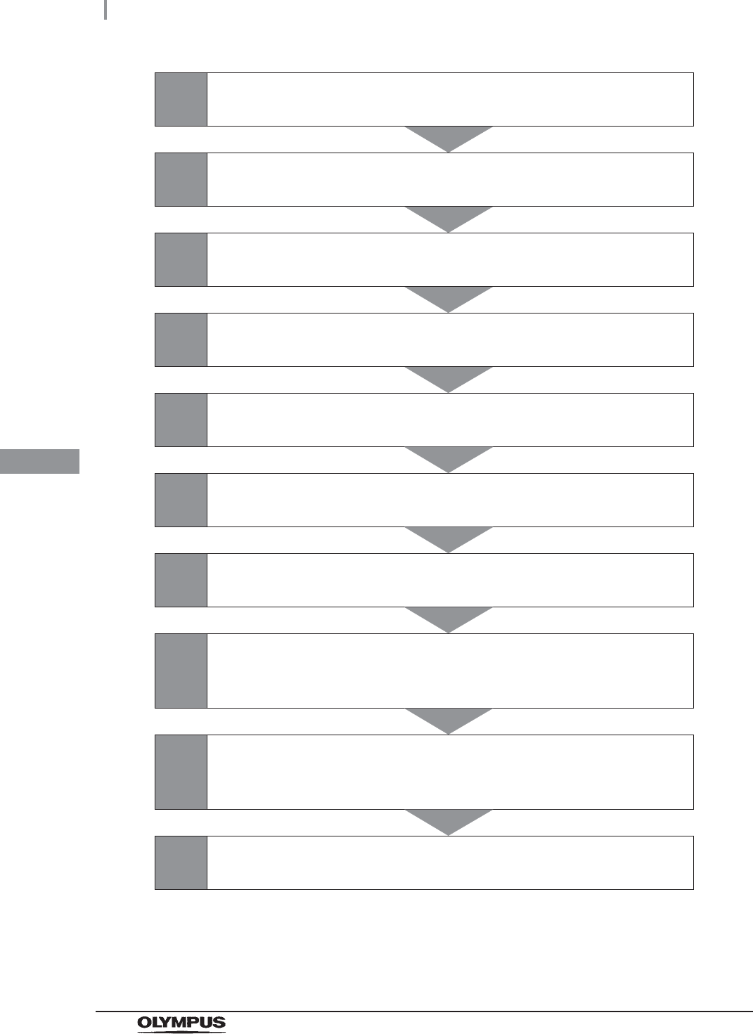
Outline of reprocessing operation in the OER-Elite
Inspection before reprocessing
Reprocessing operation in the OER-Elite
1
Checking the disinfectant solution concentration level and
entering the check result.
Section 3.7 on page 69
1Select the Reprocessing program.
Section 6.5 on page 160
2
Loading of endoscopes and accessories.
• Scope ID entry
• Loading endoscopes and accessories
• Attaching the connecting tubes
• Leak test air tube loading
• Other data entry
Section 6.6 on page 163
3Inspection before starting reprocessing process.
Section 6.7 on page 216
4Reprocessing.
Section 6.8 on page 220
5Removing the endoscopes and accessories.
Section 6.9 on page 228

158
6.4 Worst case load condition of endoscopes and accessories
OER-Elite OPERATION MANUAL
Ch.6
Before placing endoscopes and accessories, confirm that your endoscopes and accessories do not
exceed the worst case load condition.
For worst case load condition of endoscopes, see Table 6.1.
For worst case load condition of accessories, see Table 6.2.
CAUTION
Endoscopes that exceed the listed specification or present new features that may
create additional disinfection challenges should not be reprocessed in the
OER-Elite.
Worst case load condition of endoscopes
Table 6.1
6.4 Worst case load condition of endoscopes and
accessories
Item Condition Remarks column
Number of endoscopes Max 2 endoscopes Some endoscope can be
reprocessed simultaneously. For
details on combination of endoscope,
refer to the provided “List of
compatible Endoscopes/Connecting
Tubes <OER-Elite>”.
Channel length Max 1,680 mm
(Working length)
Working length of endoscope is
specified in the endoscope’s
instruction manual. This condition is
applied only when two endoscopes
are reprocessed at one time. For
details on combination of endoscope,
refer to the provided “List of
compatible Endoscopes/Connecting
Tubes” <OER-Elite>.
Channel inner diameter Min 1.2 mm
Max 6.0 mm
Channel inner diameter of the
endoscope is specified in the
endoscope’s instruction manual.
Number of channel (lumen) Max 2 instrument/suction channel
External shape/dimension Endoscope that is fully submerged is
acceptable.
For check point of “fully submerged”,
refer to Section 6.7, “Inspection
before starting reprocessing
process”.

6.4 Worst case load condition of endoscopes and accessories
159
OER-Elite OPERATION MANUAL
Ch.6
Worst case load condition of endoscope accessories
Table 6 . 2
NOTE
Stylus pen can be reprocessed under any condition.
Item Condition Remarks column
Compatible
accessories
Endoscope
accessories
reprocessed in the
washing case
All reusable endoscope accessories
(e.g., valves, plugs) except for
accessories written in remarks
column are compatible.
Following accessories cannot be
reprocessed in the OER-Elite.
• Cleaning brush, mouth piece and
other cleaning accessories except
for “AW channel cleaning adapter”
and “auxiliary water tube”. For
details on combination of
endoscope, refer to the provided
“List of compatible
Endoscopes/Connecting Tubes
<OER-Elite>”.
• All single-use accessories
• Injection adapter (MAJ-1235)
• Probe/Irrigation plug (MD-807)
• Balloon sheath connector
(MAJ-667)
• Connector section of MH-246
(Balloon sheath)
• Balloon applicator (MAJ-564,
MAJ-864)
• Light guide cable/adapter
• Camera head
• Endotherapy accessories except
for “Distal hood” and “Distal
attachment”
• Forceps Suction Plug (MH-405)
• Video converter
Endoscope
accessories
reprocessed in the
reprocessing basin.
Following accessories can be
reprocessed in the reprocessing
basin.
• Ultrasonic probe
• UPD probe
• Auxiliary water tube
Number and
combination of
accessories
Endoscope
accessories
reprocessed in the
washing case
All set of compatible accessories per
endoscopes installed in the
reprocessing basin can be
reprocessed at one time.
For details on combination of
endoscope, refer to the provided “List
of compatible
Endoscopes/Connecting Tubes
<OER-Elite>”.
Endoscope
accessories
reprocessed in the
outside of washing
case
Endoscope accessories reprocessed
in the outside of washing case should
be treated the same as endoscopes
reprocessed in the basin.
For details on combination of
endoscope, and/or endoscope
accessory refer to the provided “List
of compatible
Endoscopes/Connecting Tubes
<OER-Elite>”.
160
6.5 Basic operation for reprocessing
OER-Elite OPERATION MANUAL
Ch.6
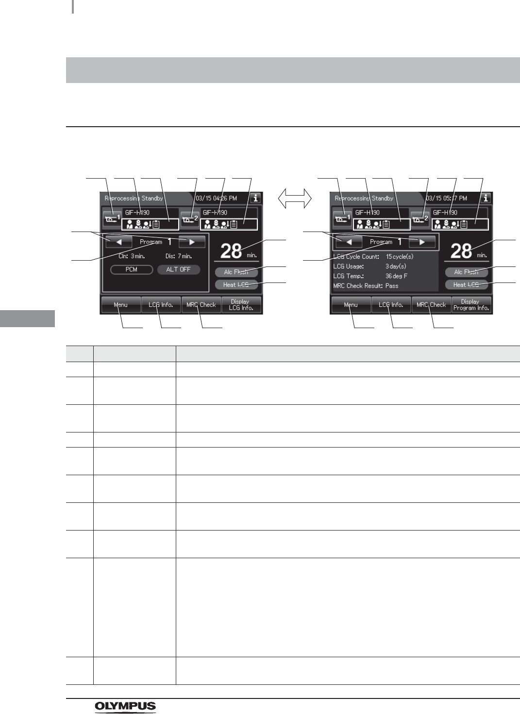
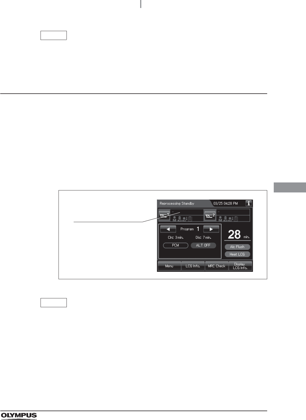
Reprocessing standby screen
Select the program by pressing the program selection buttons.
6.5 Basic operation for reprocessing
No. Nomenclature Description
1 Scope 1 button Goes to the ID information screen associated with the first endoscope.
2 Model number of
scope 1
Displays the model number of the first endoscope. It is blank when the Scope ID is not
entered.
3 ID status of scope 1 Displays the input status of patient ID, physician ID, user ID (load), and procedure ID
associated with the first scope.
4 Scope 2 button Goes to the ID information screen associated with the second endoscope.
5 Model number of
scope 2
Displays the model number of the second endoscope. It is blank when the Scope ID is
not entered.
6 ID status of scope 2 Displays the input status of patient ID, physician ID, user ID (load), and procedure ID
associated with the second scope.
7 Program selection
button
Press these buttons to select the reprocessing program.
8 Program number
display
Displays the selected reprocessing program number. For details of the reprocessing
program number, refer to “Reprocessing Program” on the next page.
9 Process time Displays the process time of the selected reprocessing program.
If any of the following methods are used to input the scope ID, the reprocessing time will
be extended by 3 minutes.
The scope ID master card is used
The scope ID is entered using the software keyboard
The pre-registered scope ID is recalled
Any endoscope with a forceps elevator will take an additional 3 minutes to reprocess.
10 Alcohol flush
indicator
Indicate that the Alcohol Flush is incorporated in the reprocessing program. Alcohol
flush cannot be eliminated from the reprocessing program.
1
7
810
11
12
2 3 4 5 6
9
13 14
1
7
810
11
12
2 3 4 5 6
9
13 14
6.5 Basic operation for reprocessing
161
OER-Elite OPERATION MANUAL
Ch.6
11 Heat LCG indicator Indicate that the Heat LCG is incorporated in the reprocessing program. Heat LCG
cannot be eliminated from the reprocessing program.
12 Menu button Returns to the Menu screen,
13 LCG Info. button Goes to the LCG info. screen.
14 MRC Check Result
button
Goes to the MRC Check Result entry screen.
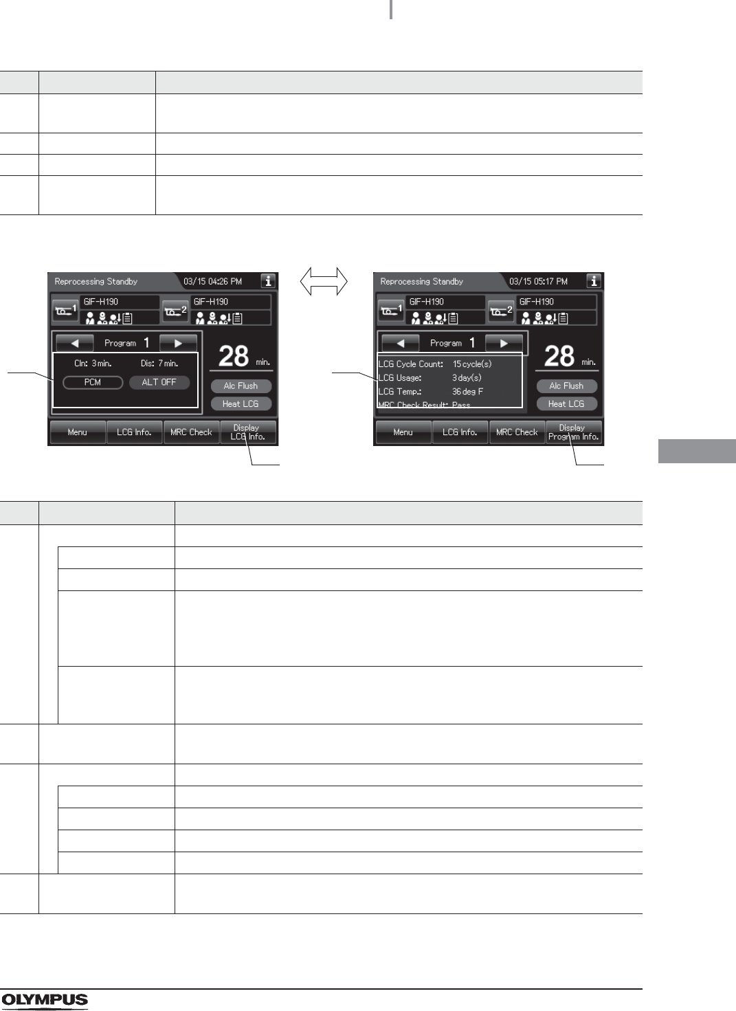
No. Nomenclature Description
1 Program information Displays information about the selected reprocessing program.
Cln. Displays the cleaning time
Dis. Displays the disinfecting time.
Channel Monitor
indicator
If “PCM” is displayed, channel monitor is executed in the cleaning and disinfection
process.
If “FCM” is displayed, channel monitor is executed in the cleaning, disinfection and
rinsing process.
Auto Leak Test
indicator
If “ALT ON” is displayed, auto leak test is incorporated in the reprocessing process.
If “ALT OFF” is displayed, auto leak test is not incorporated in the reprocessing
process.
2 Display LCG Info.
Button
Press to display the disinfectant solution information on the area of No.1.
Refer to No.3.
3 LCG information Displays information about the current disinfectant solution.
LCG Cycle Count Usage count of the disinfectant solution.
LCG Usage Number of days that have elapsed since preparation of the disinfectant solution.
LCG Temp. Temperature of disinfectant solution during reprocessing process.
MRC Check Result Input result of MRC check.
4 Display Program Info.
button
Press to display the information of the selected reprocessing program on the area of
No.3. Refer to No.1.
No. Nomenclature Description
1
2 4
3
162
6.5 Basic operation for reprocessing
OER-Elite OPERATION MANUAL
Ch.6
Reprocessing program
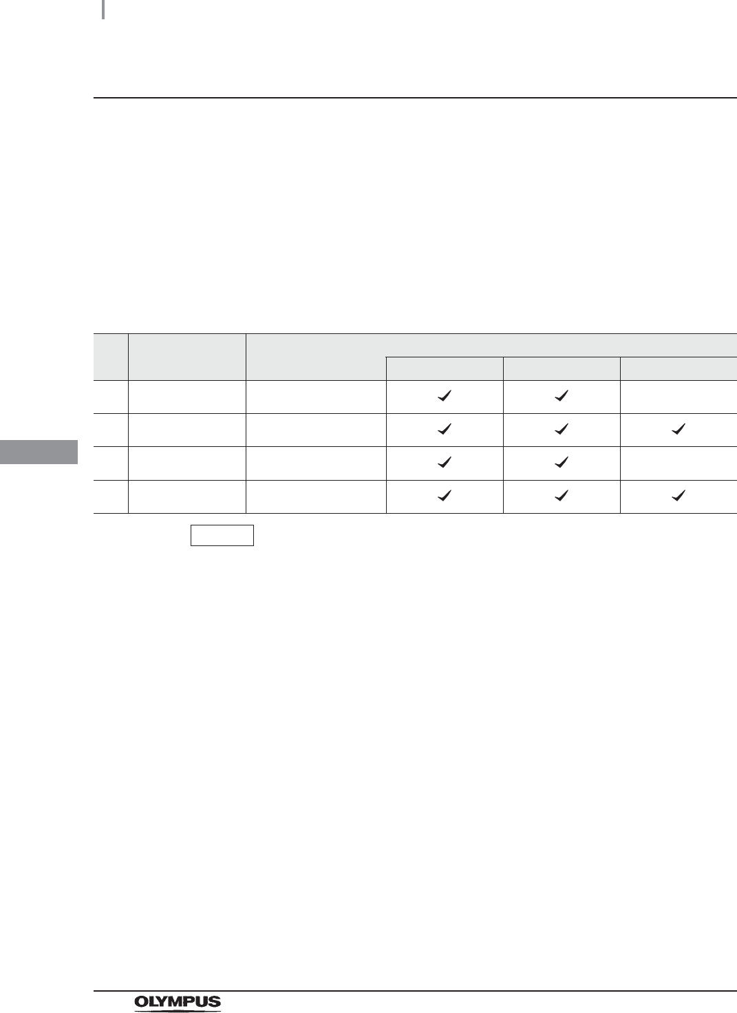
OER-Elite has four reprocessing programs. Selection of the reprocessing programs depends on the
settings of ALT and Channel monitoring. See the table below for the details of the programs.
If any of the following methods are used to input the scope ID, the reprocessing time will be extended
by 3 minutes.
The scope ID master card is used
The scope ID is entered using the software keyboard
The pre-registered scope ID is recalled
Any endoscope with a forceps elevator will take an additional 3 minutes to reprocess.
NOTE
• The program number to be displayed after turning the power ON the reprocessor is
the one which was executed just before turning the power OFF the reprocessor.
• The reprocessing time of the programs in which auto leak test is ON is
2 – 7 minutes longer than that of the programs in which Auto leak test is OFF.
• The reprocessing time of the programs in which Channel monitoring is Full is
approximately 8 minutes longer than that of the programs in which Channel
monitoring is Partial.
No. Auto Leak Test Channel Monitoring (Process that the channel monitoring executes.)
Cleaning Disinfection Rinse
1 OFF Partial (PCM)
2 OFF Full (FCM)
3 ON Partial (PCM)
4 ON Full (FCM)
6.6 Loading of endoscopes and accessories
163
OER-Elite OPERATION MANUAL
Ch.6
Outline of loading operation of endoscopes and
accessories
6.6 Loading of endoscopes and accessories
1Input scope ID of first endoscope.
on page 165
2Loading of first endoscope in the reprocessing basin
on page 166
3Loading of the accessories of first endoscope (valves, etc.).
on page 173
4Attaching the connecting tubes loading to first endoscope.
on page 177
5Attaching the Leak test air tube loading to first endoscope. (*)
on page 189
6Loading of auxiliary water tube of first endoscope. (*)
on page 186
7Input connection port of first endoscope. (*)
on page 194
8
Input results of manual cleaning and leak test on page of first
endoscope. (*)
on page 195
9Input user ID, physician ID, and patient ID of first endoscope. (*)
on page 196
164
6.6 Loading of endoscopes and accessories
OER-Elite OPERATION MANUAL
Ch.6
10 Input scope ID of second endoscope.
on page 197
11 Loading of second endoscope in the reprocessing basin.
on page 197
12 Loading of the accessories of second endoscope (valves, etc.).
on page 202
13 Attaching the connecting tubes loading to second endoscope.
on page 205
14 Attaching the Leak test air tube loading to second endoscope. (*)
on page 213
15 Loading of auxiliary water tube of second endoscope. (*)
on page 211
16 Input connection port of second endoscope. (*)
on page 214
17
Input results of manual cleaning and leak test on page of second
endoscope. (*)
on page 214
18
Input user ID, physician ID, and patient ID of second endoscope.
(*)
on page 214
19 Loading stylus pen.
on page 215
6.6 Loading of endoscopes and accessories
165
OER-Elite OPERATION MANUAL
Ch.6
NOTE
Operations marked with (*) may be skipped depending on the endoscope to be
reprocessed or the setting of the reprocessor.
Input scope ID of first endoscope
To maintain an endoscope reprocessing record, this reprocessor is capable of recognizing the
individual scope ID that identifies the endoscope being reprocessed.
The scope ID can be input with the following methods.
• Input from RFID
• Software keyboard input
• Input from pre-registered information
For details on the input methods, refer to Section 3.6, “Entering ID” (If applicable).
When the scope ID is input, the touch screen displays the model number of the first endoscope.
Figure 6.1
NOTE
Before entering scope ID of second endoscope, complete IDs entry associated with
first endoscope. If scope ID of second endoscope is entered without completing IDs
entry associated with first endoscope, the message is displayed on the touch
screen.
Displays the model number
of the first endoscope

166
6.6 Loading of endoscopes and accessories
OER-Elite OPERATION MANUAL
Ch.6
Loading of first endoscopes in the reprocessing basin
OER-Elite can reprocess up to two endoscopes at one time. For details on combination of endoscope
that can be reprocessed simultaneously, refer to “List of Compatible Endoscopes/Connecting Tubes
<OER-Elite>”.
Before placing endoscopes and accessories, thoroughly review the worst case load condition of
endoscopes and accessories instructed in Section 6.4, “Worst case load condition of endoscopes and
accessories”, and confirm that your endoscopes and accessories do not exceed the worst case load
condition.
The instruction below is compiled assuming the loading of standard-type gastroenterological
endoscopes. If a different type of endoscope(s) is to be reprocessed, refer to the provided “OER-Elite
Quick Reference Guide”.
WARNING
• The injection adapter (MAJ-1235) cannot be reprocessed with the reprocessor. If it
is placed in the washing case, reprocessing of this adapter will not be effective.
• When placing the endoscopes in the basin, make sure that the major parts such as
the insertion tube and universal cord are loaded correctly. If the endoscopes are
placed carelessly with many parts overlapping incorrectly reprocessing may be
ineffective.
• Do not attempt to reprocess an endoscope that is not designated for use with the
reprocessor. Do not reprocess two endoscopes that should not be reprocessed
simultaneously with each other. Doing so will prevent the reprocessor from
functioning properly and may endanger the safety of the patient and operator. In
this case, the durability of the reprocessor and its ancillary equipment cannot be
guaranteed.
• Place only the valves and other specified endoscope components in the washing
case in the reprocessing basin. If any object other than those specified is placed in
the washing case, reprocessing of the endoscope valves will not be effective.
• When reprocessing an endoscope with a forceps elevator, the connecting tube
must be connected to the distal end of the insertion tube. Otherwise, the
reprocessing may be insufficient. For the appropriate connecting tube, refer to the
“List of Compatible Endoscope/Connecting Tubes <OER-Elite>”. For the
connection method of the connecting tube, refer to the instruction manual for the
connecting tube.
• If the distal end cap of an endoscope is removable, remove the distal end cap
before putting the endoscope in the reprocessing basin. Otherwise, reprocessing
may be insufficient.
• Do not obstruct the circulation port inside the reprocessing basin. Otherwise, the
liquid feed pressure on the endoscopes will be decreased and reprocessing will be
insufficient.

6.6 Loading of endoscopes and accessories
167
OER-Elite OPERATION MANUAL
Ch.6
WARNING
• Before starting the reprocessing cycle, be sure to confirm that the endoscopes are
installed below the disinfectant solution level index line on the cover of float switch
(long) and the cover of float switch (long) is attached firmly. If the endoscope is not
fully submerged in the disinfectant solution, reprocessing may be insufficient.
• When loading endoscopes, always be sure to disconnect cleaning accessories
used for manual process from the endoscope. Otherwise, reprocessing may be
insufficient.
• Be sure to check that the whole of endoscope and accessories is installed below
the disinfectant solution level index line on the cover of float switch (long). If the
endoscope and accessories is installed above the disinfectant solution level index
line, the reprocessing may be insufficient. Refer to Figure 6.37.
CAUTION
• When installing an endoscope that requires water-resistant cap, attach
water-resistant cap by following the instructions for the endoscope. If a cap is not
attached or a cap with moisture inside is attached, the endoscope will fail or
malfunction.
• Ensure that each endoscope is free of noticeable damage before placing it in this
reprocessor. Otherwise, fluid leak may occur during the reprocessing. If damage is
noticed, perform the leaking scope decontamination and contact Olympus for
servicing. For details on the leaking scope decontamination, refer to Section 7.15,
“Leaking scope decontamination”.
• Do not let the distal end of an endoscope drop from the retaining rack or contact the
reprocessing basin directly. Otherwise, the endoscope may be damaged.
• When the leak test air tube is not used, disconnect it from the connector and be
sure to remove it from the reprocessing basin. If reprocessing is performed without
removing it, water or disinfectant solution may enter inside the tube and may cause
a failure of the tube. Also, if the water or disinfectant solution entering the leak test
air tube during the scope leak test enters inside the endoscope, endoscope failure
may result.
• When reprocessing is started without disconnecting the unused leak test air
tube(s), error code [E024] is generated and the process stops. For detail on this
error code, refer to “When the error code [E024] is displayed during the
reprocessing process” on page 614.
• When reprocessing endoscopes, always be sure to attach the retaining rack in the
reprocessing basin. Otherwise, external surface of endoscopes may contact the
heating portion of the reprocessing basin, resulting in possible damage to
endoscopes.
168
6.6 Loading of endoscopes and accessories
OER-Elite OPERATION MANUAL
Ch.6
NOTE
• In the ID inputs for each endoscope, there is no determined order for the inputs of
the scope ID, user ID (load), physician ID, patient ID, and procedure ID.
• To input the patient ID from a bar code, it is required to connect the optional
MAJ-2130 bar code reader.
• Be sure to place the endoscopes into the reprocessing basin in the correct
orientation. Otherwise, the water or the detergent solution feed from the endoscope
may enter the inside of the nozzle and dilutes disinfectant solution inside of the
nozzle. In this case, the next MRC check will be failed even if the concentration of
LCG in the tank is above its MRC.
Loading of first endoscope in the reprocessing basin
1
1Step on the foot pedal to open the lid.
2Gently place the control section of the first endoscope on the depressed part of the
reprocessing basin located on the left of the index pin 1, refer to Figure 6.2 image.
Figure 6.2
Depressed part
Index pin 2 Index pin 1Index pin 2 Index pin 1
6.6 Loading of endoscopes and accessories
169
OER-Elite OPERATION MANUAL
Ch.6
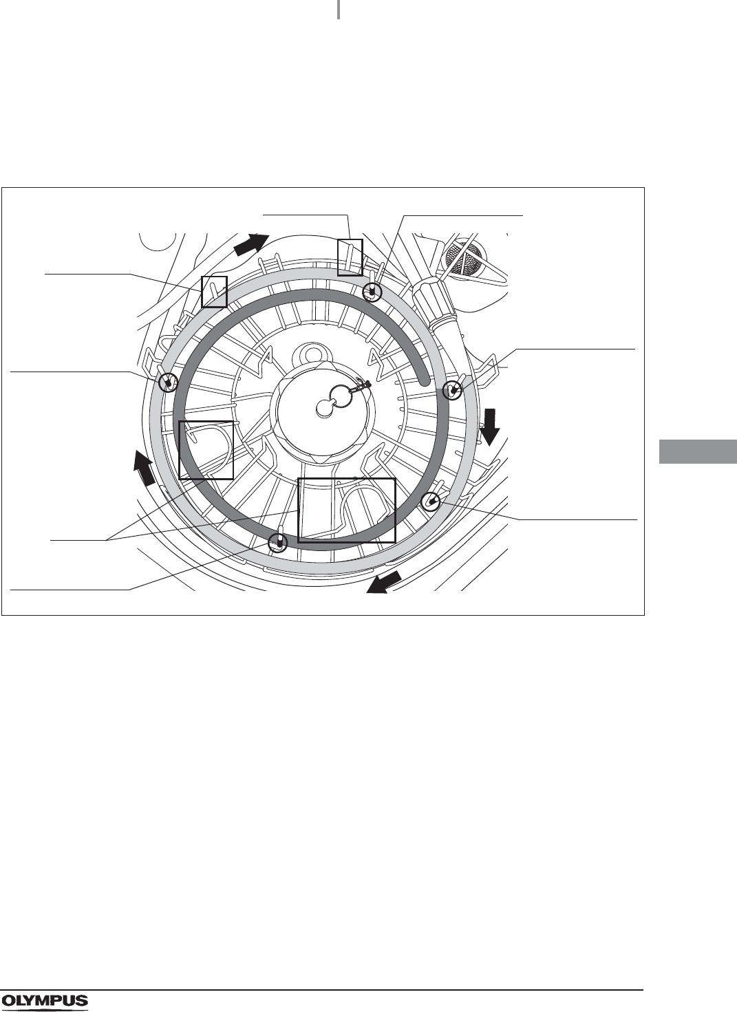
3Wrap the insertion tube clockwise around the retaining rack from the perimeter in.
Wrap the first turn of the insertion tube outside the black markings from M1 to M5 and
inside the index pin 2 and 3 (shown in light gray). Wrap the second turn inside the
black markings from M1 to M5 and outside the hooks (shown in dark gray). Refer to
Figure 6.3.
Figure 6.3
Black Marking M5
Black Marking M1
Black Marking M2
Black Marking M4
Black Marking M3
Index pin 3
Index pin 2
Hooks
170
6.6 Loading of endoscopes and accessories
OER-Elite OPERATION MANUAL
Ch.6
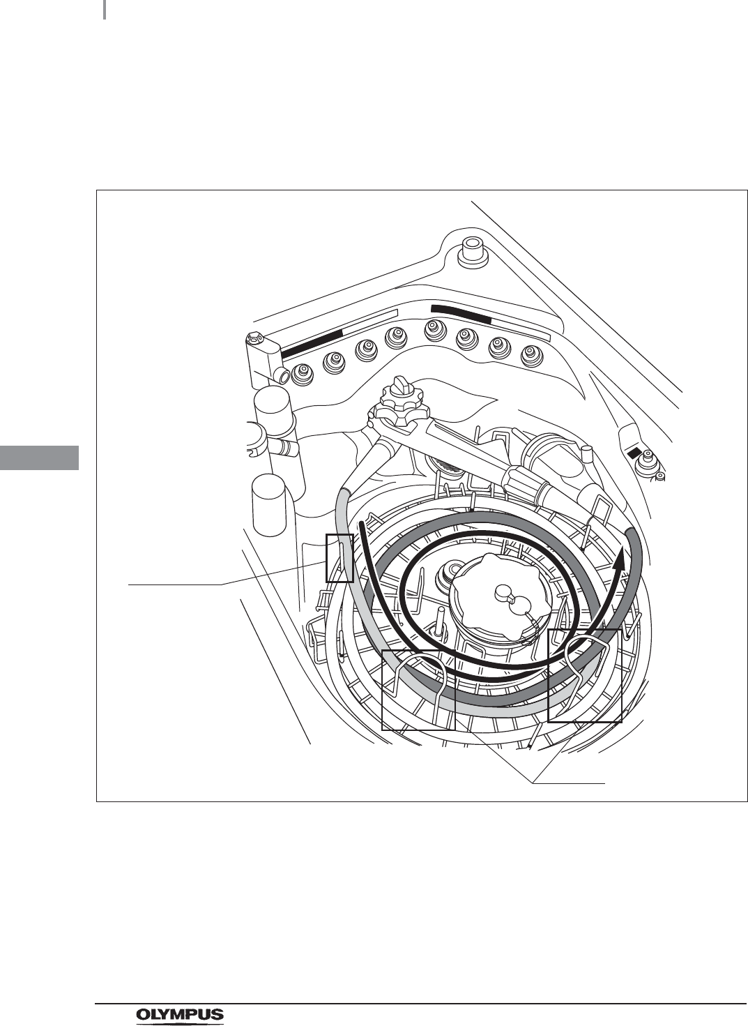
4Wrap the universal cord (light and dark gray) in a counterclockwise direction on the
right of index pin 3 in the inside section (for detail, refer to the Figure 6.4) on the
retaining rack by placing it under the hooks so that it will not move upward. If the
scope ID tag is attached to the endoscope, move the scope ID tag toward the
endoscope connector. Straighten the ID tag’s band if it is twisted.
Figure 6.4
Index pin 3
Hooks
6.6 Loading of endoscopes and accessories
171
OER-Elite OPERATION MANUAL
Ch.6
5Gently place the first endoscope connector on the specified position on the right side
of the reprocessing basin (above the drain port, and inside the Black Marking: M2).
Do not put the endoscope connector in the step area.
Figure 6.5
Step area
Black Marking: M2
(Do not put the endoscope on the
step area.)
Drain port
172
6.6 Loading of endoscopes and accessories
OER-Elite OPERATION MANUAL
Ch.6
6Adjust the positions of the insertion tube and universal cord to minimize overlapping.
Also, adjust the positioning of the insertion tube’s distal end by turning the angulation
control knobs (lever) on the control section. Again, make sure that the universal cord
is placed on the inside of the hooks.
Figure 6.6

6.6 Loading of endoscopes and accessories
173
OER-Elite OPERATION MANUAL
Ch.6
Loading of the accessories of first endoscope (valves,
etc.)
The valves and specified parts of the endoscopes installed in the reprocessing basin can be
reprocessed in the washing case together with forceps plugs and AW channel cleaning adapters.
Before placing endoscopes and accessories, thoroughly review the worst case load condition of
endoscopes and accessories instructed in Section 6.4, “Worst case load condition of endoscopes and
accessories”, and confirm that your endoscopes and accessories do not exceed the worst case load
condition.
WARNING
• Place only the valves and AW channel cleaning adapters of the endoscopes
installed in the reprocessing basin and the specified scope parts in the washing
case. If an item other than the valves of the installed endoscopes and specified
scope parts are installed, the valves and specified scope parts cannot be
reprocessed sufficiently.
• Be sure to clean the accessories manually before placing in the washing case.
Otherwise, the reprocessing may be ineffective.
• The biopsy valve should be opened before being placed in the reprocessing basin.
Also, other accessories that can be disassembled should be disassembled before
being placed in the washing case. Otherwise, they may not be sufficiently
reprocessed.
• Do not put endoscope accessories such as valves and plugs on outside of the
washing case. Otherwise, reprocessing of endoscope accessories may be
insufficient.
• Always be sure to close the lid of washing case before starting reprocessing.
Otherwise, reprocessing of endoscope accessories may be insufficient.
174
6.6 Loading of endoscopes and accessories
OER-Elite OPERATION MANUAL
Ch.6
1Check if the accessories that can be disassembled are disassembled completely.
Figure 6.7
2Open the washing case cover and put the accessories (e.g., biopsy valve, air/water
valve, suction valve, auxiliary water inlet cap) into the washing case.
Figure 6.8
Example
Forceps/Irrigation plug (MAJ-891) Suction valve (MAJ-207)
Biopsy valve (MAJ-419)
6.6 Loading of endoscopes and accessories
175
OER-Elite OPERATION MANUAL
Ch.6
3Put the AW channel cleaning adapter in the washing case and place the indicator
plate outside the washing case. Ensure the indicator plate is placed between both
hooks. Place the chain of the AW channel cleaning adapter in the designated grooves
on the rim of the washing case.
Figure 6.9
WARNING
• Do not pile up the chain of AW channel cleaning adapter. Otherwise, effectiveness
of the reprocessing of AW channel cleaning adapter may be compromised.
• Do not place more than two AW channel cleaning adapters in the case. Otherwise,
the reprocessing may be insufficient.
• When the chains of AW channel cleaning adapter are set on the rim, make sure
that the indicator plates of AW channel cleaning adapters are set between the
hooks by referring the Figure 6.43 and 6.53. Otherwise, the reprocessing of AW
channel cleaning adapter may be insufficient.
Groove on the rim of
the washing case.
Chains of the adapter placed
in the groove on the rim.
Hooks
176
6.6 Loading of endoscopes and accessories
OER-Elite OPERATION MANUAL
Ch.6
WARNING
• Do not place endoscope on the indicator plate of AW channel cleaning adapter.
Otherwise, reprocessing of AW channel cleaning adapter may be insufficient.
• The indicator plates of the AW channel cleaning adapters should not be placed in
an area other than specified. Otherwise, the adapters may encounter strong force
when the lid is closed which may cause damage to the endoscopes, AW channel
cleaning adapters, retaining rack and/or lid.
CAUTION
Place the AW channel cleaning adapters in the reprocessing basin without twisting
of the chains of the adapters. If a chain is twisted excessively, the chain may be
caught by the washing case and the adapter, washing case and/or lid may be
damaged.
4Close the washing case cover so that the chains of AW channel cleaning adapter are
not caught between the case and the cover. Place the indicator plate of AW channel
cleaning adapter on the endoscopes as shown in the Figure 6.10.
Figure 6.10

6.6 Loading of endoscopes and accessories
177
OER-Elite OPERATION MANUAL
Ch.6
Attaching the connecting tubes loading to first endoscope
The OER-Elite is shipped with two sets of four connecting tubes: MAJ-2110, MAJ-2111, MAJ-2112, and
MAJ-2113. Check the “List of Compatible Endoscopes/Connecting Tubes <OER-Elite>” to confirm
whether these connecting tubes are the correct connecting tubes for the particular model endoscope
that you are reprocessing. If the “List of Compatible Endoscopes/Connecting Tubes <OER-Elite>”
indicates that a different connecting tube is required, contact Olympus to obtain the necessary
connecting tube. Each Olympus endoscope requires a specific connecting tube (or tubes). Do not
attempt to reprocess any endoscope without the correct connecting tube.
Before using connecting tubes, be sure to inspect the connecting tubes as instructed in Section 5.7,
“Inspecting the connecting tubes and leak test air tube”.
WARNING
• Each connecting tube is supplied with an instruction manual that describes its
method of attachment. Follow these instructions to attach the connecting tube to
the OER-Elite and the endoscope. Incorrect attachment will result in insufficient
reprocessing.
• After attaching each connecting tube, visually confirm that there are no
irregularities such as kinking, accidental detachment or use of wrong connecting
tube and confirm that each connecting tube is firmly attached. If any irregularity is
observed, it must be corrected. Otherwise, the reprocessing may be insufficient.
• If you are reprocessing two endoscopes in the OER-Elite, and a problem is
observed with the connecting tubes on one of the endoscopes, correct the problem
and then reprocess both endoscopes again, starting from the beginning.
• Disconnect the connecting tubes from the connectors on the reprocessor whenever
the tubes are not used for reprocessing. If reprocessing is performed while the
unnecessary tubes are connected, the effectiveness of reprocessing may be
reduced.
• When closing the lid, do not get the connecting tube caught between the
reprocessing basin and lid and make sure the endoscopes and the washing case
are not touching the lid. Otherwise, the endoscopes, the connecting tubes, the
washing case and the reprocessor may be reprocessed insufficiently or get
damaged or water leakage from the reprocessing basin may occur.
• To confirm the correct connecting tubes are attached to the endoscope, always
refer to the instruction manuals for endoscope or the latest “List of Compatible
Endoscopes/Connecting Tubes <OER-Elite>”. Using incorrect connecting tubes
may result in ineffective reprocessing of endoscopes. If you do not have the latest
“List of Compatible Endoscopes/Connecting Tubes <OER-Elite>”, contact
Olympus.
178
6.6 Loading of endoscopes and accessories
OER-Elite OPERATION MANUAL
Ch.6
WARNING
• If two endoscopes are reprocessed simultaneously, connect the connecting tube to
the connector in the basin in order of number of the connector (e.g., connector A1
should be connected to the 1st endoscope, connector A2 should be connected to
the 2nd endoscope).
• If connecting tube is connected to the wrong connector, channel blockage
monitoring and channel connectivity monitoring cannot work properly (e.g.,
connecting tube for 1st endoscope is connected to the connector of 2nd
endoscope).
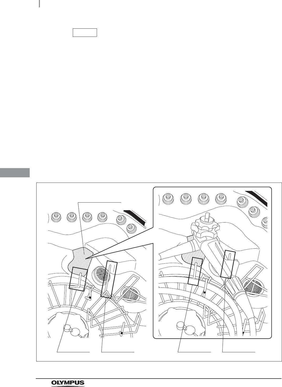
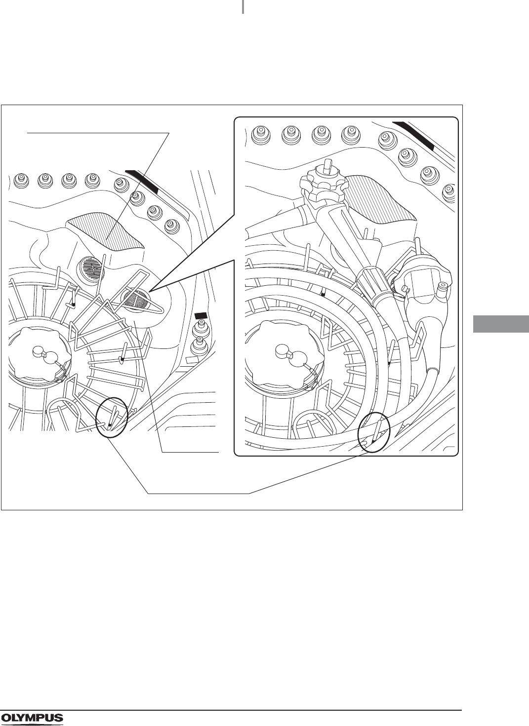
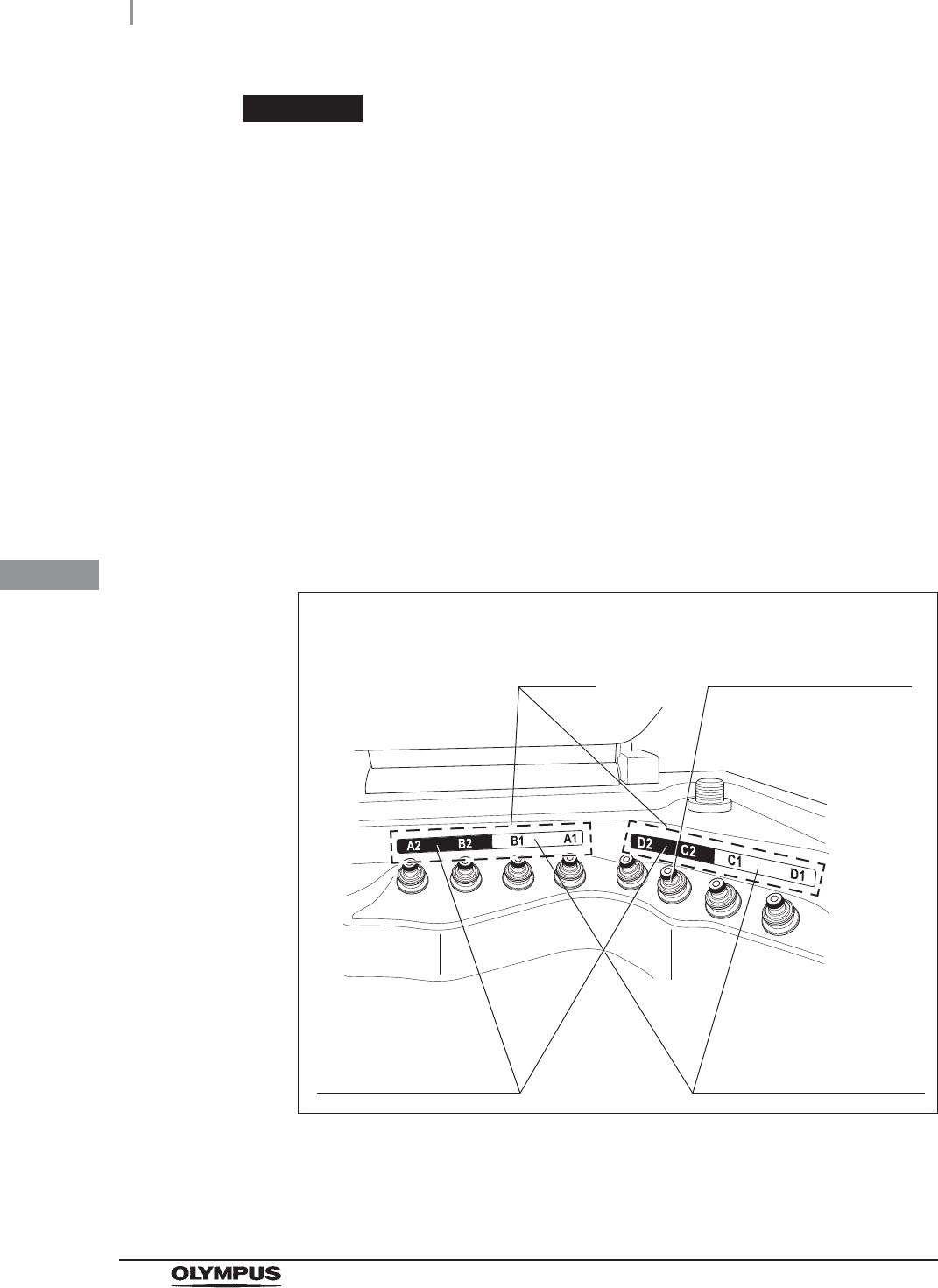
Labels and color of connector used for the first endoscope
Labels are provided in the reprocessing basin to distinguish each connector. It also provides
information about which connectors are used for the first endoscope and which are used for the
second endoscope.
Each connector has a specified color identical to the color of connecting tubes and leak test air
tubes that can connect to the connector.
Figure 6.11
Color of connector is
identical to the color of
connecting tubes that can
connect to the connector.
White colored label
means this connector is
used in most cases for
first endoscope.
Black colored label
mean this connector is
used in most cases for
second endoscope.
Labels
6.6 Loading of endoscopes and accessories
179
OER-Elite OPERATION MANUAL
Ch.6
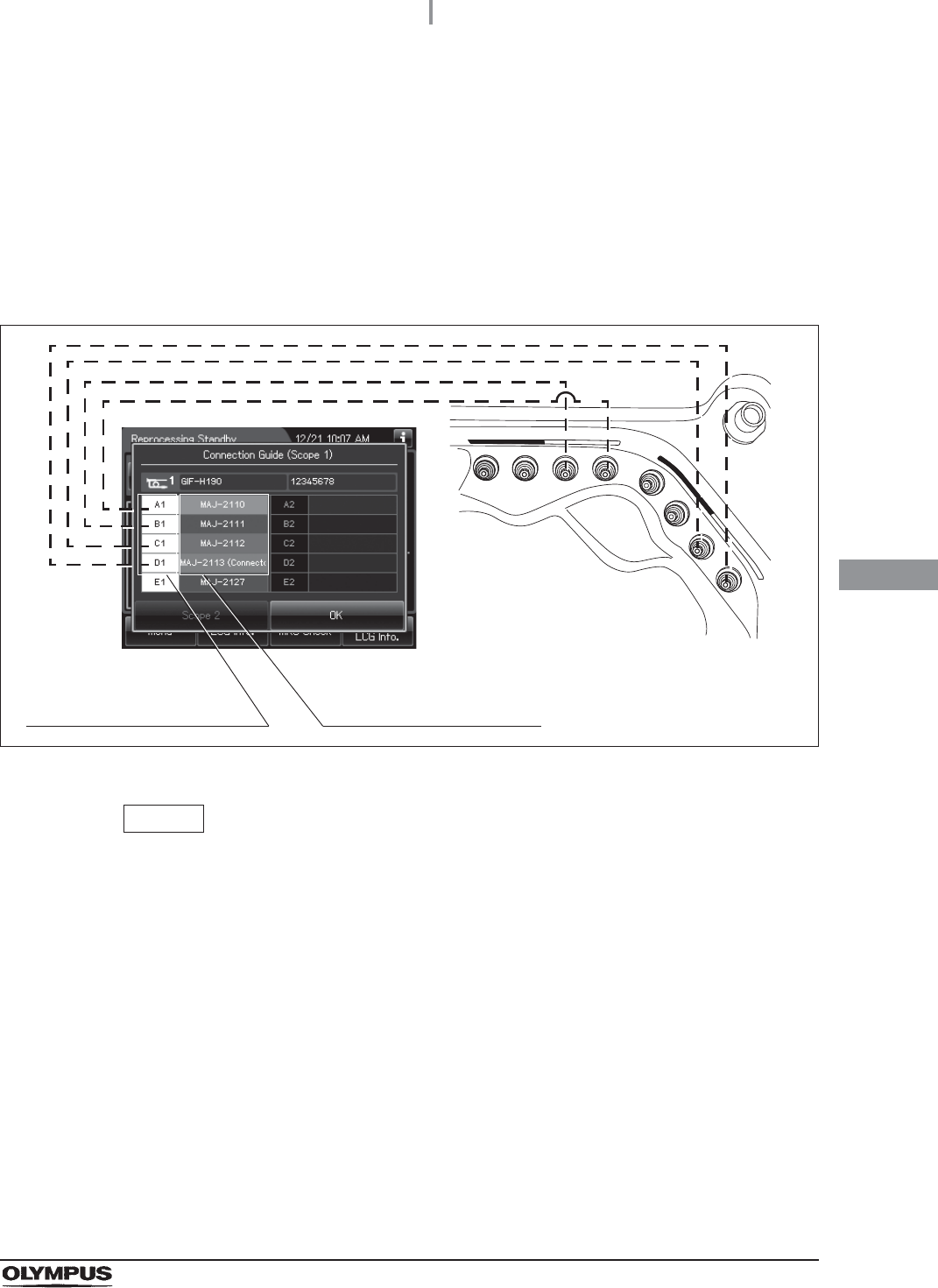
Connection guide of first endoscope
When connection guide setting is activated, connection guide screen is displayed after inputting
scope ID with RFID.
Connection Guide screen provides the information about the type of connecting tubes required
for the endoscope and the location of connectors that these connecting tubes are connected.
The below figure is example case. If endoscope with two instrument channel ports is set, it is
required to connect B2. Refer to the connection guide information and “List of Compatible
Endoscopes/Connecting Tubes <OER-Elite>”.
Figure 6.12
NOTE
When the scope ID is input using the master scope ID card or with the manual
input, the Connection Guide screen is not displayed. In this case, connect the
designated connecting tubes by referring to the “List of Compatible
Endoscopes/Connecting Tubes <OER-Elite>”.
Background colors identical
to the connector colors.
Identical colors to the
colors of labels attached
on the reprocessing basin.
180
6.6 Loading of endoscopes and accessories
OER-Elite OPERATION MANUAL
Ch.6
Connection of the connecting tubes of first endoscope
The instruction below is compiled assuming the loading of standard-type gastroenterological
endoscopes using standard-set of connecting tubes MAJ-2110, MAJ-2111, MAJ-2112, and
MAJ-2113.
WARNING
• If two endoscopes are reprocessed simultaneously, connect the connecting tube to
the connector in the basin in order of number of the connector (e.g., connector A1
should be connected to the 1st endoscope, connector A2 should be connected to
the 2nd endoscope).
• If connecting tube is connected to the wrong connector, channel blockage
monitoring and channel connectivity monitoring cannot work properly (e.g.,
connecting tube for 1st endoscope is connected to the connector of 2nd
endoscope).
NOTE
If reprocessing a different type of endoscope(s) requires different types of
connecting tubes, refer to the instruction manual for the connecting tube.
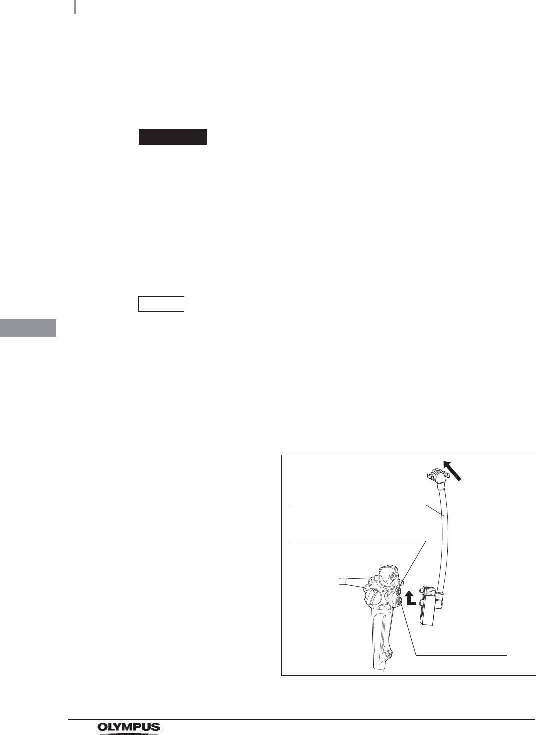
1Insert the endoscope side connector of the MAJ-2110 connecting tube all the way into
the suction cylinder and air/water supply cylinder of the endoscope. After the
endoscope side connector is inserted until it is stopped at the bottom, keep pushing
the connector and slide it toward the eyepiece/remote switch side to secure the
connection.
Figure 6.13
Air/water and
suction cylinders
Connecting tube (MAJ-2110)
To the light blue
connectors.
Eyepiece/remote switch side
6.6 Loading of endoscopes and accessories
181
OER-Elite OPERATION MANUAL
Ch.6
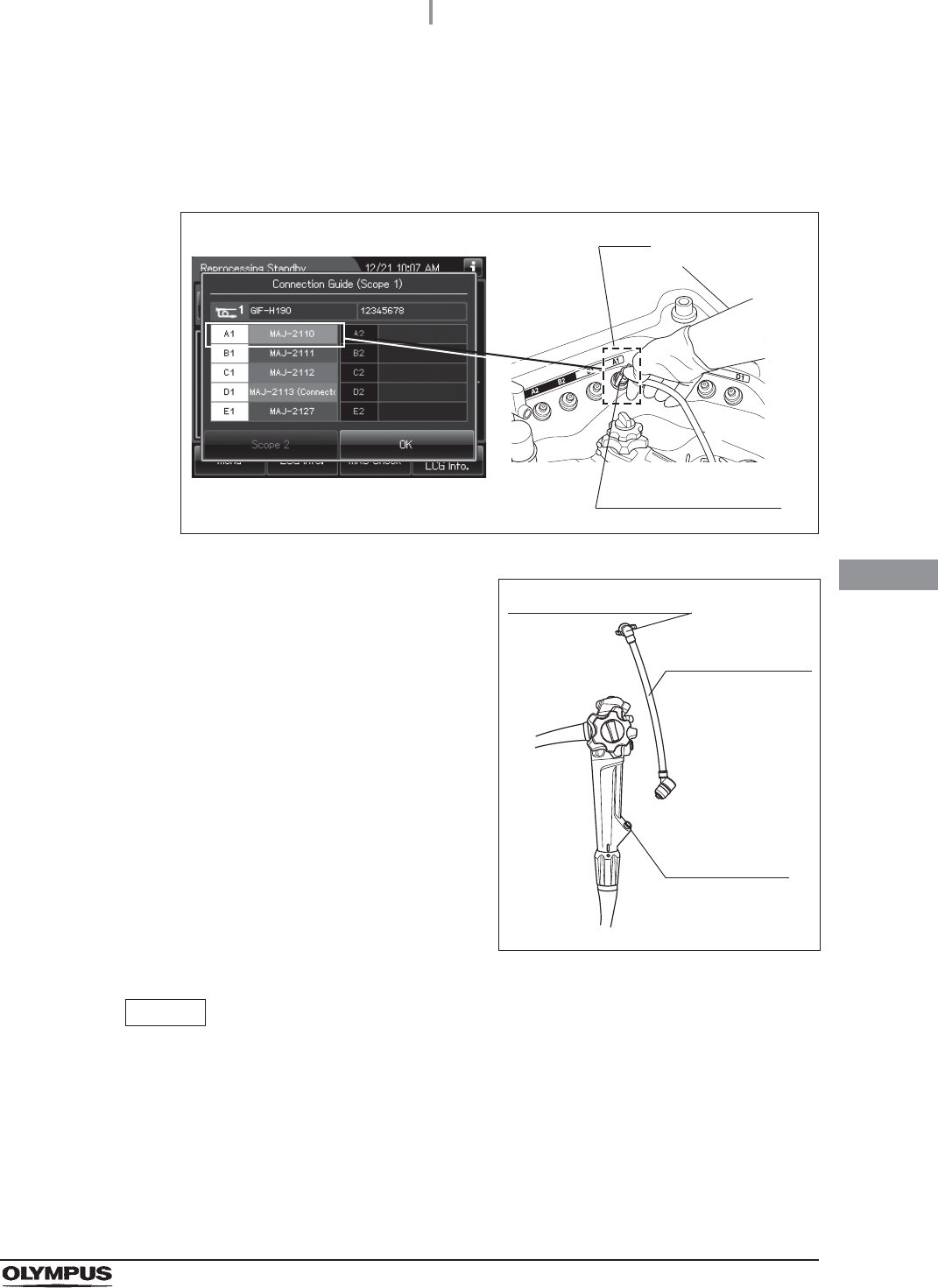
2Insert the reprocessor-side connector of the MAJ-2110 connecting tube into the
connector with the same color (refer to the Connection Guide screen) of the
reprocessing basin by pushing in until it clicks. In this case, connect to the connector
A1 for the first endoscope.
Figure 6.14
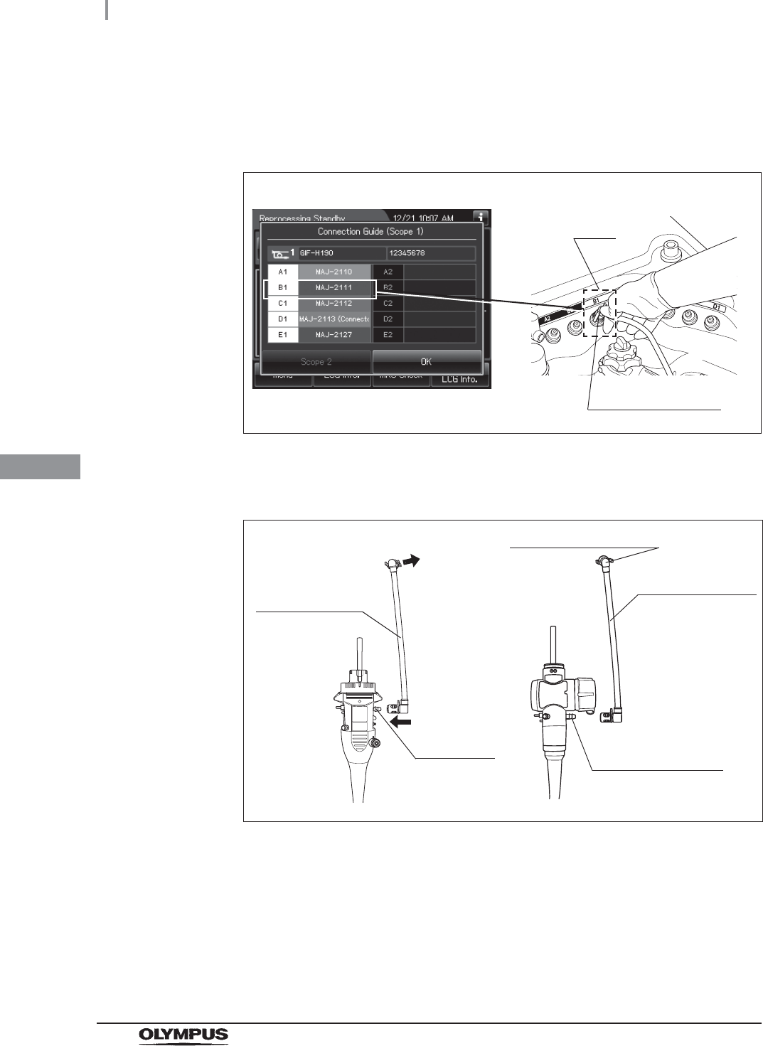
3Insert the MAJ-2111 connecting tube into the
instrument channel port of the endoscope until
it clicks.
Figure 6.15
NOTE
Conform the control section of the first endoscope on the depressed part of the
reprocessing basin located on the left of the index pin. For detail of image, refer to
Figure 6.15 and Figure 6.2.
Light blue connectors
For first endoscope A1
Instrument
channel port
Connecting tube
(MAJ-2111)
To the blue connectors.
182
6.6 Loading of endoscopes and accessories
OER-Elite OPERATION MANUAL
Ch.6
4Insert the reprocessor-side connector of the MAJ-2111 connecting tube into the
connector with the same color (refer to the Connection Guide screen) of the
reprocessing basin by pushing in until it clicks. In this case, connect to the connector
B1 for the first endoscope.
Figure 6.16
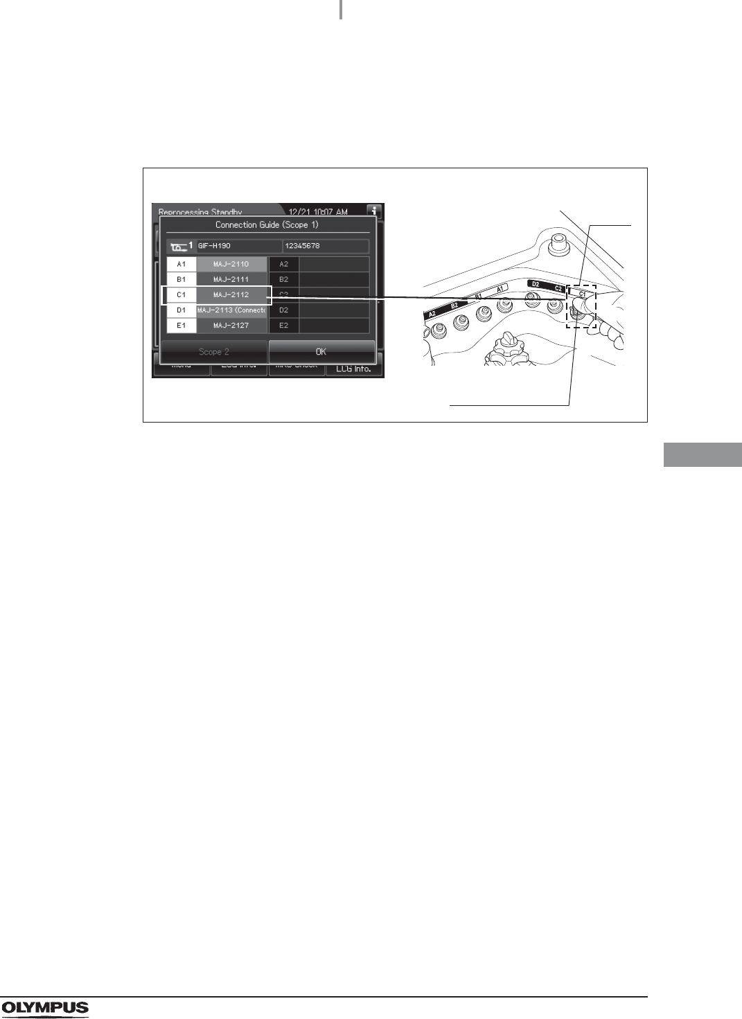
5Insert the MAJ-2112 connecting tube into the suction connector of the endoscope until
it clicks. For details, refer to Figure 6.17.
Figure 6.17
Blue connectors
For first endoscope
B1
Suction connector
Connecting tube
(MAJ-2112)
To the green connectors.
Connecting tube
(MAJ-2112)
Suction
connector
To the green connectors.
6.6 Loading of endoscopes and accessories
183
OER-Elite OPERATION MANUAL
Ch.6
6Insert the reprocessor-side connector of the MAJ-2112 connecting tube into
connector with the same color (refer to the Connection Guide screen) of the
reprocessing basin by pushing in until it clicks. In this case, connect to the connector
C1 for the first endoscope.
Figure 6.18
For first endoscope
Green connectors
C1
184
6.6 Loading of endoscopes and accessories
OER-Elite OPERATION MANUAL
Ch.6
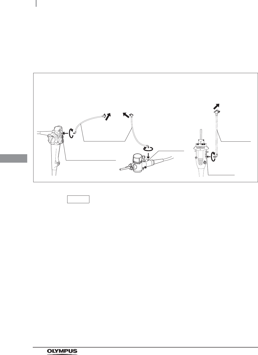
7Insert the MAJ-2113 connecting tube into the endoscope side connector straight into
the endoscope’s auxiliary water inlet/elevator channel plug, and turn the outer ring
clockwise to connect firmly. Refer to Figure 6.19 for the three options for mounting the
MAJ-2113.
When using the MAJ-2138 refer to “Loading of auxiliary water tube of first
endoscope” on page 186 and Figure 6.21 on page 186.
Figure 6.19
NOTE
If reprocessing the auxiliary water tube together with the endoscope, optional
MAJ-2138 connecting tube is used instead of MAJ-2113. Also, the auxiliary water
tube cleaning setting should be activated when using optional MAJ-2138
connecting tube. For details on setting, refer to Section 4.16, “Auxiliary water tube
cleaning setting”.
To the orange
connectors.
To the orange
connectors.
Connecting tube
(MAJ-2113)
Auxiliary water inlet/
Elevator channel plug
Auxiliary
water inlet
To the orange
connectors.
Connecting
tube
(MAJ-2113)
Auxiliary
water inlet
For scope with inlet on the
190 series scope connector
For scope with inlet on
the 180 series or older
scope connector
For scope with inlet/plug on
the control panel

6.6 Loading of endoscopes and accessories
185
OER-Elite OPERATION MANUAL
Ch.6
8Insert the reprocessor-side connector of the MAJ-2113 connecting tube into
connector with the same color (refer to the Connection Guide screen) of the
reprocessing basin by pushing in until it clicks. In this case, connect to the connector
D1 for the first endoscope.
Figure 6.20
NOTE
When reprocessing an endoscope with a forceps elevator, the connecting tube
must be connected to the distal end of the insertion tube.
For the appropriate connecting tube, refer to the “List of Compatible
Endoscope/Connecting Tubes <OER-Elite>”.
For the connection method of the connecting tube, refer to the instruction manual
for the connecting tube.
9If the auto leak test is not included in the reprocessing program, press the OK button
on the touch screen. If the auto leak test is programmed, perform the operation in
“Connection of the leak test air tubes of first endoscope” on page 192.
For first endoscope
Orange connectors
D1
186
6.6 Loading of endoscopes and accessories
OER-Elite OPERATION MANUAL
Ch.6
Loading of auxiliary water tube of first endoscope
When the auxiliary water tube cleaning setting is activated, an endoscope with the auxiliary
water supply function can be reprocessed together with the auxiliary water tube.
To reprocess the auxiliary water tube together with the endoscope, the optional MAJ-2138
connecting tube is required. For the setting change method, refer to Section 4.16, “Auxiliary
water tube cleaning setting”.
WARNING
If an endoscope incorporating the auxiliary water supply function is not
reprocessed together with the auxiliary water tube, do not use the MAJ-2138
connecting tube. Otherwise, the auxiliary water tube connection port is left open
and the fluid may not be supplied to the endoscope channels. When reprocessing
an endoscope incorporating the auxiliary water supply function alone without the
auxiliary water tube, be sure to use only the provided MAJ-2113 connecting tubes.
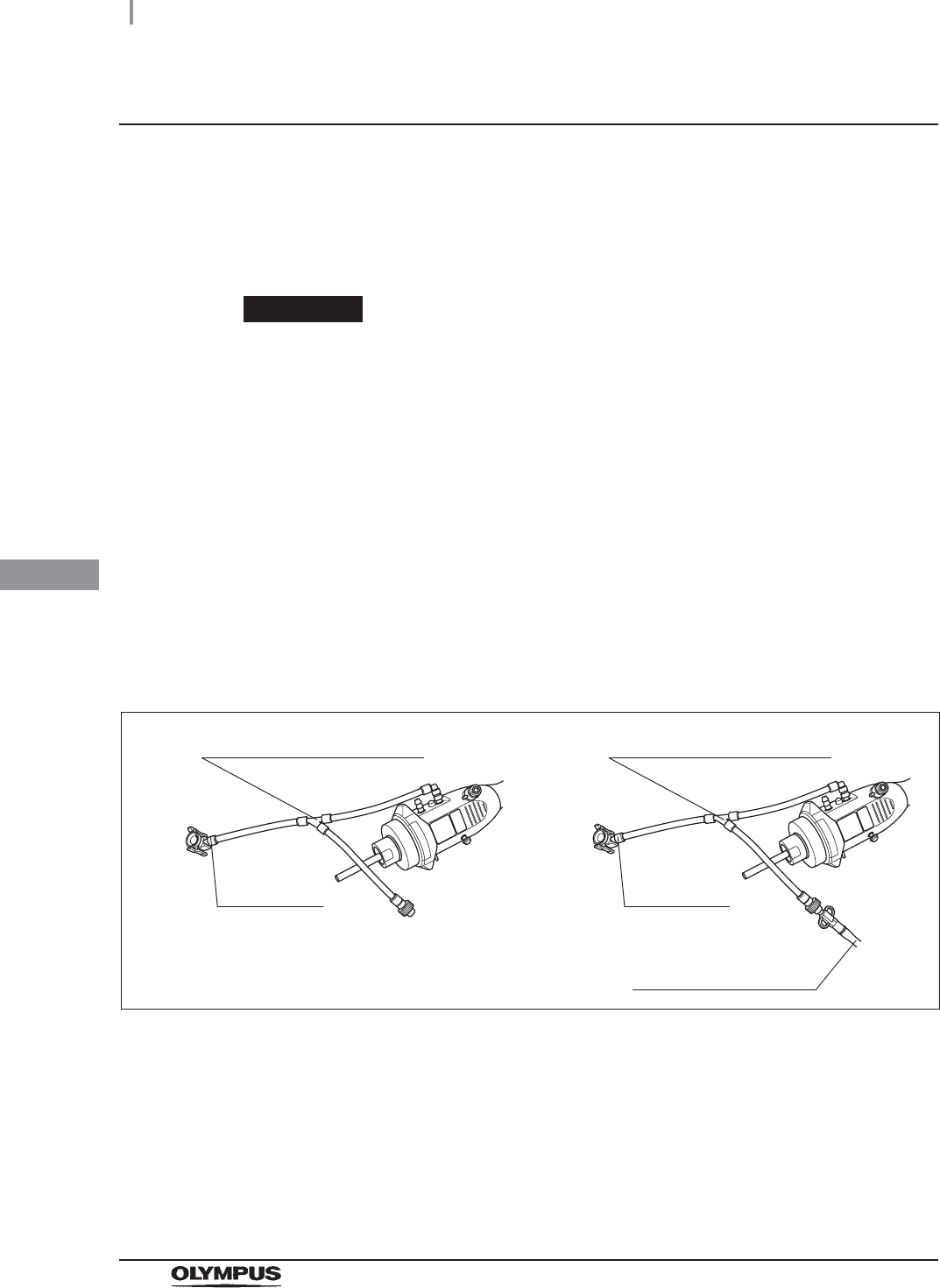
1Insert the endoscope side connector of the MAJ-2138 connecting tube into the
auxiliary water inlet of first endoscope. Turn the outer ring clockwise to connect firmly.
Refer to right of the Figure 6.21.
2Insert the auxiliary water tube side connector of the MAJ-2138 connecting tube into
the Luer port of the auxiliary water tube. Turn the outer ring clockwise to connect
firmly. Refer to left of the Figure 6.21.
Figure 6.21
Auxiliary water tube
(MAJ-855/MAJ-2021)
To the orange
connectors.
MAJ-2138 connecting tube
To the orange
connectors.
MAJ-2138 connecting tube

6.6 Loading of endoscopes and accessories
187
OER-Elite OPERATION MANUAL
Ch.6
3Insert the reprocessor-side connector of the MAJ-2138 connecting tube into the
connector of the same color (refer to the Connection Guide screen) of the
reprocessing basin by pushing in until it clicks. For detail, refer to Figure 6.22.
Figure 6.22
4Temporarily place the indicator plate of the AW channel cleaning adapter on the
washing case. Wrap the auxiliary water tube clockwise around on the inner section of
the retaining rack. Do not to place the first endoscope and auxiliary water tube on the
indicator plate of the AW channel cleaning adapter.
Figure 6.23
For first endoscope
Orange connectors
D1
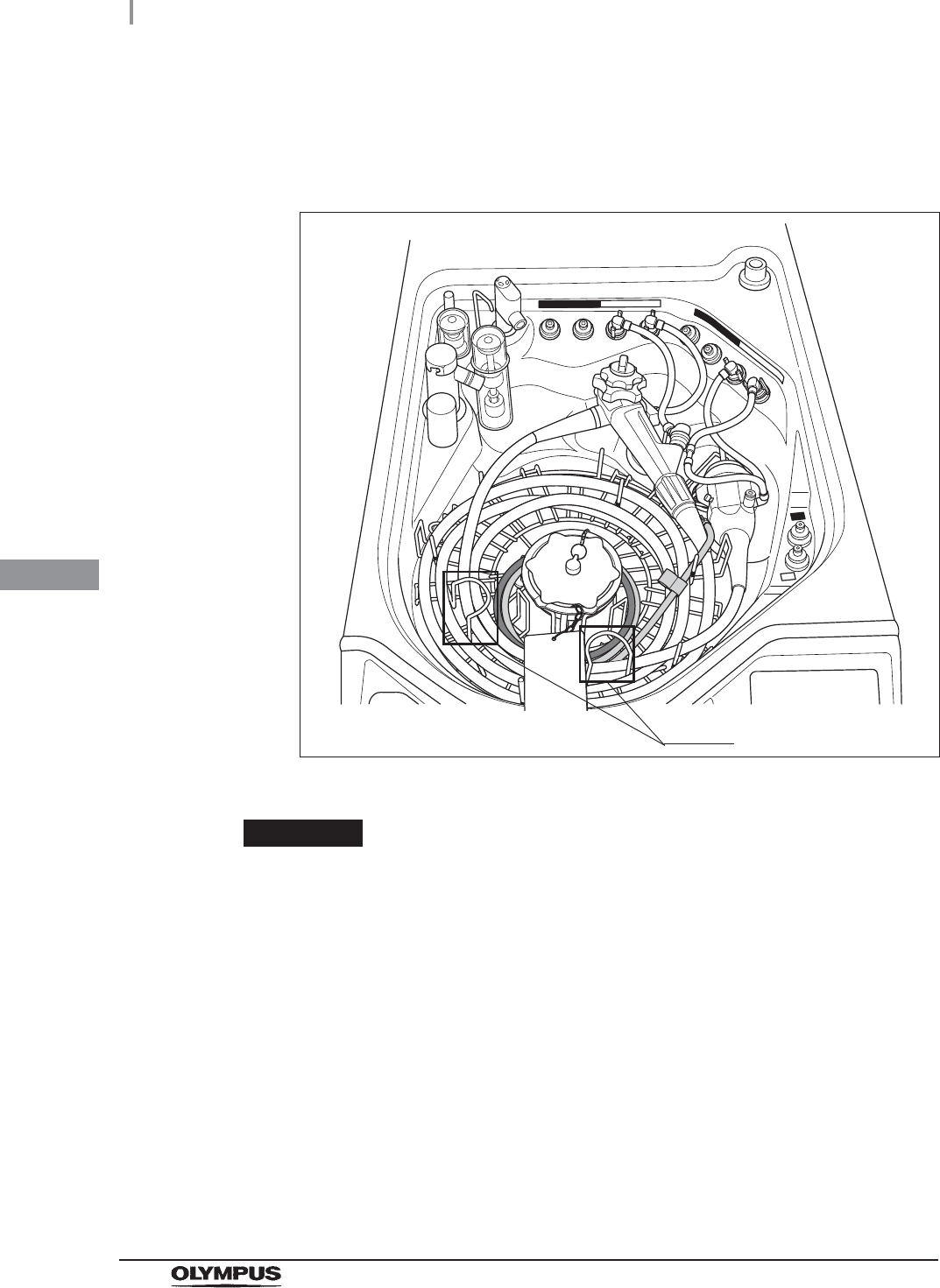
188
6.6 Loading of endoscopes and accessories
OER-Elite OPERATION MANUAL
Ch.6
WARNING
Do not wrap the auxiliary water tube on the AW channel cleaning adapters. If the
auxiliary water tubes are on the plate or the chain of the AW channel cleaning
adapters, the reprocessing of AW channel cleaning adapter may be insufficient.
5After loading the first endoscope and auxiliary water tube, place the indicator plate of
the AW channel cleaning adapter on the first endoscope and auxiliary water tube.
Make sure that the indicator plates of AW channel cleaning adapters are set between
hooks.
Figure 6.24
Hooks

6.6 Loading of endoscopes and accessories
189
OER-Elite OPERATION MANUAL
Ch.6
Attaching the Leak test air tube loading to first endoscope
When the auto leak test is included in the reprocessing program, connect the leak test air tube.
CAUTION
• Disconnect the leak test air tube from the connectors on the reprocessor whenever
the tubes are not used for leak test. If reprocessing is performed while the
unnecessary tubes are connected, fluid may get inside the leak test air tube and
could cause it to malfunction. The fluid inside the tube may also damage the
endoscope when the leak test is performed next time.
• The leak test air tube will disconnect easily if it is not attached properly or if the lock
lever is degraded. Air cannot be fed properly if the leak test air tube is bent. In
these cases, an accurate leak test is not possible.
• Make sure that there are no cracks, breaks, fissures, scratches, or stains on the
leak test air tube according to Section 5.7, “Inspecting the connecting tubes and
leak test air tube”. Using an abnormal or damaged leak test air tube may result in
an inaccurate leak test or cause the endoscope to malfunction. If an irregularity is
found with the leak test air tube, replace it with a new one and retry the leak test.
• Do not connect the leak test air tube if the inside of the tube, the endoscope’s
venting connector, or the reprocessor’s leak test connector is wet. Doing so could
allow water to get inside the endoscope and cause the endoscope to malfunction.
• When connecting the leak test air tube, ensure that the tube connector is fully and
properly attached. Improper connection will prevent the endoscope from being
pressurized, preventing an accurate leak test. This could also allow water to get
inside the endoscope and cause the endoscope to malfunction.
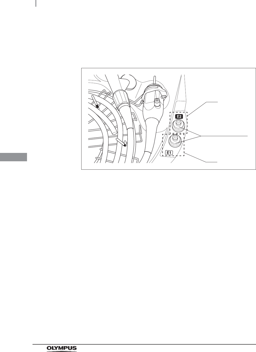
190
6.6 Loading of endoscopes and accessories
OER-Elite OPERATION MANUAL
Ch.6
Labels and color of connector used for the first endoscope
Labels are provided in the reprocessing basin to distinguish each connector. It also provides
information about which connector is used for the first endoscope or the second endoscope.
Each connector has a specified color identical to the color of the connecting tubes and leak test
air tubes that can connect to the connector.
Figure 6.25
Purple connectors
E2
E1
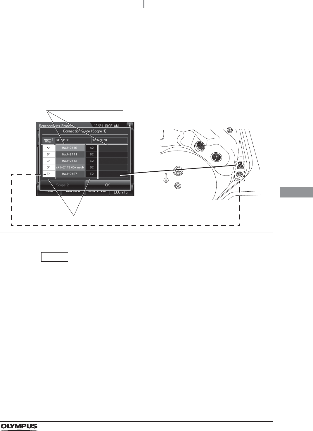
6.6 Loading of endoscopes and accessories
191
OER-Elite OPERATION MANUAL
Ch.6
Connection guide of first endoscope
When the scope ID was input by reading the ID tag with the RFID reader of the reprocessor,
connect the specified connecting tubes to the connectors on the endoscope and reprocessing
basin by following the instructions given by the Connection Guide screen displayed on the touch
screen. The position relationship between the connectors shown on the Connection Guide
screen and those in the reprocessing basin is shown below.
Figure 6.26
NOTE
When the scope ID is input using the master scope ID card or with the manual
input, the Connection Guide screen is not displayed.
Background colors identical to
the connector colors.
Identical colors to the colors of labels
attached on the reprocessing basin.
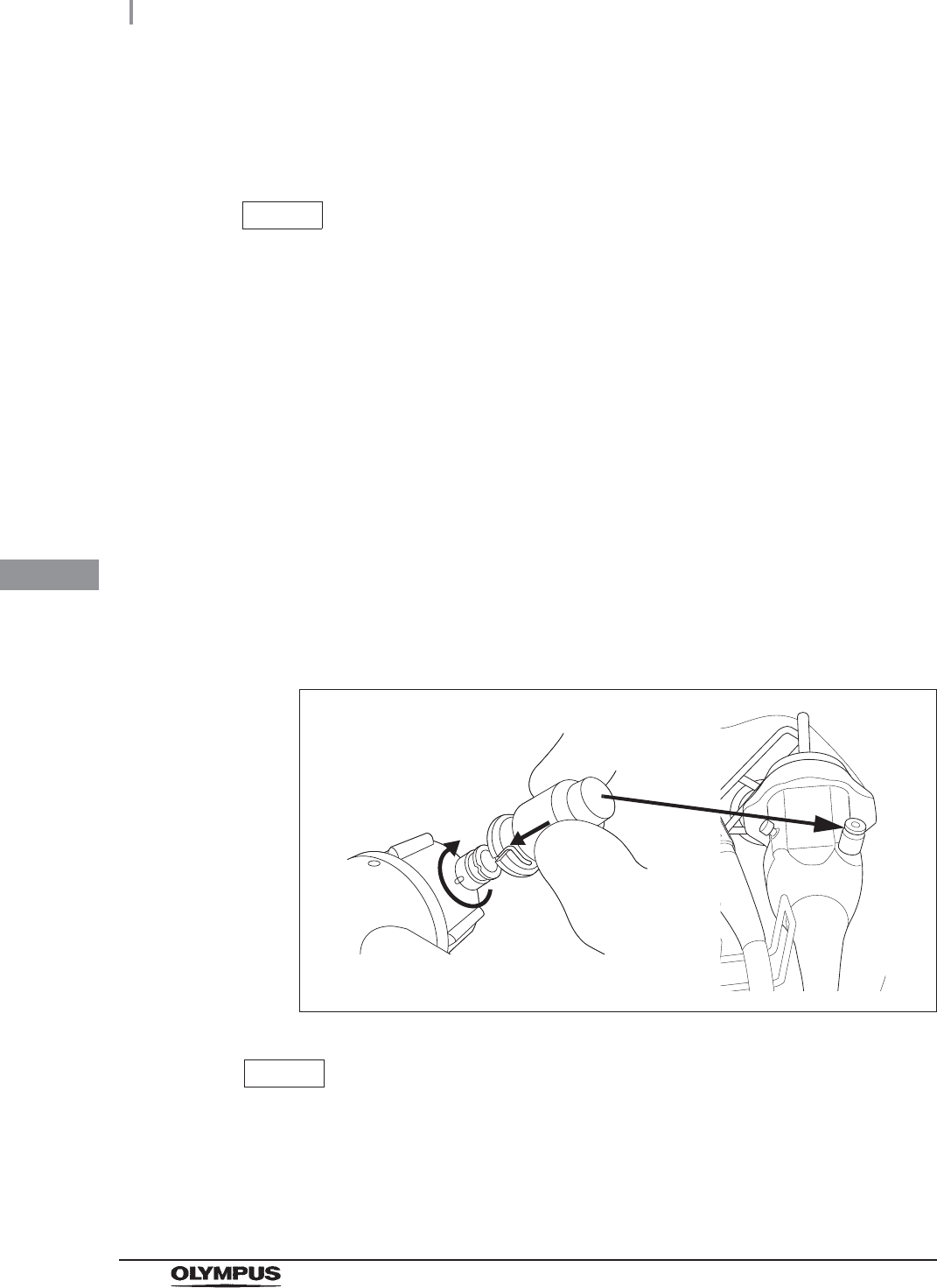
192
6.6 Loading of endoscopes and accessories
OER-Elite OPERATION MANUAL
Ch.6
Connection of the leak test air tubes of first endoscope
Connect the leak test air tube to connectors on the endoscope and reprocessing basin by
following the instructions.
NOTE
• Certain endoscopes are incapable of auto leak test. For the endoscopes which are
compatible with the auto leak test, refer to the “List of Compatible
Endoscopes/Connecting Tubes <OER-Elite>”.
• Do not connect the leak test air tube to the wrong connector (e.g., leak test air tube
for 1st endoscope is connected to the connector for 2nd endoscope). Otherwise,
auto leak testing cannot work properly since the error occurs.
1Wipe the venting connector of the first endoscope or that of the waterproof cap with a
clean cloth immersed in 70% ethyl alcohol or 70% isopropyl alcohol.
2If the leak test connector E1 in the reprocessing basin is wet, remove moisture by
wiping the whole connector with a clean cloth.
3Aligning the groove on the metal connector of the MAJ-2127 leak test air tube with the
pin on the venting connector of the first endoscope or that of the waterproof cap,
insert the connector into the port by turning the connector by 90° in the clockwise
direction while pushing it.
Figure 6.27
NOTE
Conform the first endoscope connector on the specified position on the right side of
the reprocessing basin (above the drain port). For detail of image, refer to
Figure 6.5 on page 171.
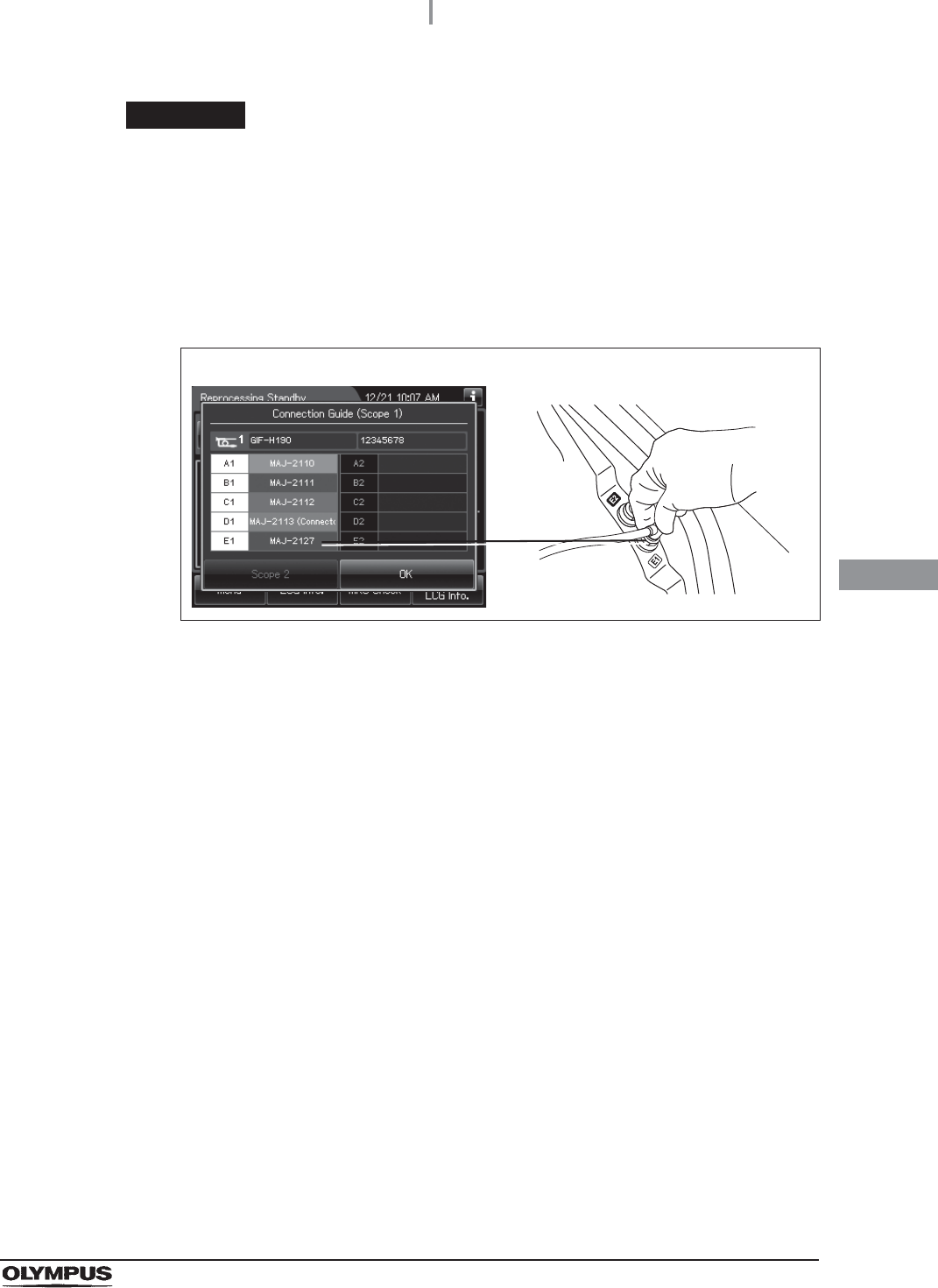
6.6 Loading of endoscopes and accessories
193
OER-Elite OPERATION MANUAL
Ch.6
CAUTION
Be sure to connect the leak test air tube to the specified leak test connector in the
reprocessing basin. If auto leak test is performed while the leak test air tube is
connected to a wrong connector, the auto leak test may become incapable of
correct leak detection.
4Insert the reprocessor-side connector of MAJ-2127 leak test air tube into the
connector E1 until its lock lever is securely engaged with a snap.
Figure 6.28
5Press the “OK” button on the touch screen to close the Connection Guide screen.
First endoscope
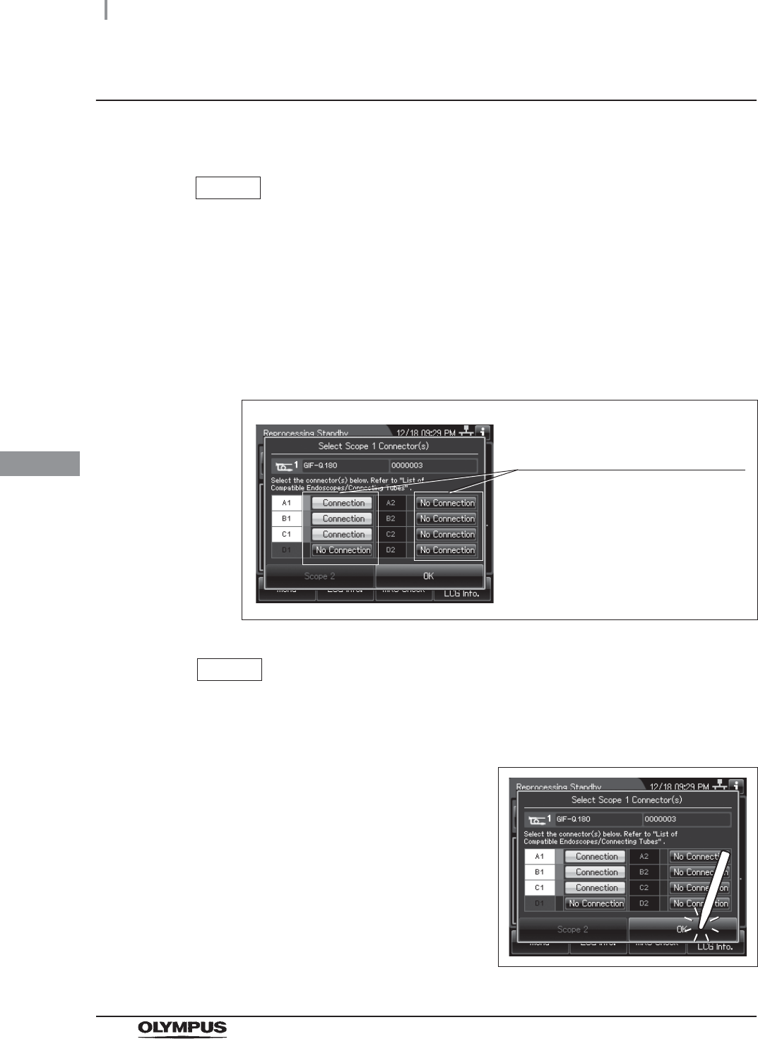
194
6.6 Loading of endoscopes and accessories
OER-Elite OPERATION MANUAL
Ch.6
Input connection information of first endoscope
When the scope ID is entered by method other than RFID, connection information screen described
below is displayed on the touch screen. In this case, input of connection information is required.
NOTE
According to the input of connection information, the OER-Elite monitors the
channel flow to check the internal valves are properly operated. This function does
not support the detection of channel blockage and disconnection of connecting
tube of endoscope side.
1On the Connection information screen, press the “No Connection” buttons
corresponding to the reprocessing basin connectors to which the connecting tubes
are connected. The “No Connection” indicator will now change to “Connection”.
Figure 6.29
NOTE
If status other than the actual connecting tube connection status is selected, error
code [E024] is generated during reprocessing and the reprocessing process stops.
2Press the “OK” button.
Figure 6.30
Each press of either button alternates
the displayed button name between
“Connection” and “No Connection”.
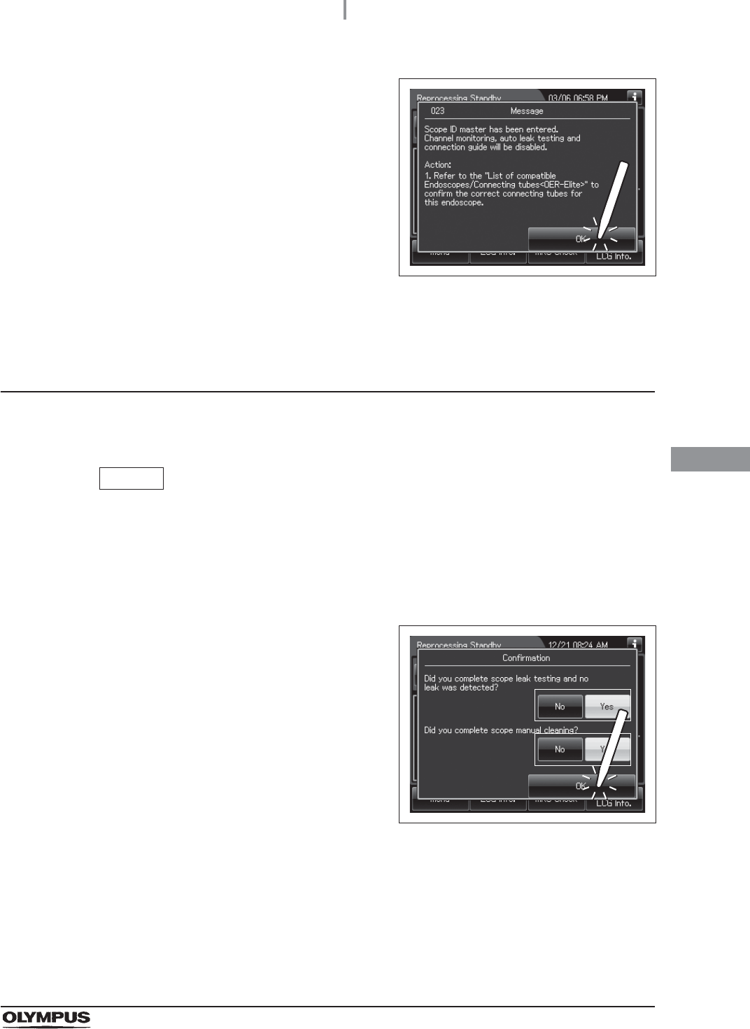
6.6 Loading of endoscopes and accessories
195
OER-Elite OPERATION MANUAL
Ch.6
Input results of manual cleaning and leak test of first
endoscope
When the manual cleaning and leak test setting is activated, result of manual cleaning and leak
test can be entered and associated with the endoscope.
NOTE
• The input of the result of manual cleaning and leak test can be disabled by
changing a setting. For details, refer to Section 4.4, “Manual cleaning and leak test
setting”.
• When No is selected either of them, reprocessing process cannot be started.
3When the “OK” button is pressed, the following
warning message is displayed. After reading
the message, press the “OK” button again.
Figure 6.31
Select whether or not the endoscope has been
cleaned manually and whether or not leak was
found during the leak testing, and press the
“OK” button.
Figure 6.32
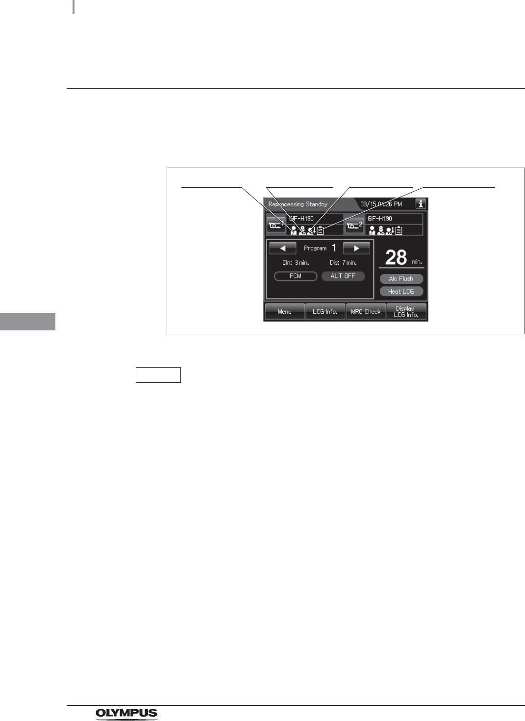
196
6.6 Loading of endoscopes and accessories
OER-Elite OPERATION MANUAL
Ch.6
Inputs user ID, physician ID, patient ID, and procedure ID
of first endoscope
User ID (load), physician ID, patient ID, and procedure ID can be entered and associated with
the endoscope. Each ID entry can be changed by settings, refer to Section 4.5 – 4.9. For details
on the input methods, refer to Section 3.6, “Entering ID” (If applicable). When ID is input, the
icon of input ID is displayed with a white icon.
Figure 6.33
NOTE
• Before entering user ID (load), physician ID, patient ID, or procedure ID of second
endoscope, complete IDs entry associated with first endoscope. If user ID (load),
physician ID, patient ID or procedure ID of second endoscope is entered without
completing IDs entry associated with first endoscope, message is displayed on the
touch screen.
• The user ID setting provides options of 2 users, 1 user and OFF as the number of
user IDs to be set. For the method of changing the use ID setting, refer to
Section 4.5, “User ID Setting”.
• The physician ID input can be omitted by changing the physician ID setting. For the
physician ID setting, refer to Section 4.6, “Physician ID setting”.
• The patient ID input can be omitted by changing the patient ID setting. For the
patient ID setting, refer to Section 4.7, “Patient ID setting”.
• The procedure ID input can be omitted by changing the procedure ID setting. For
the procedure ID setting, refer to Section 4.9, “Procedure ID setting”.
Patient ID Physician ID User ID (load) Procedure ID
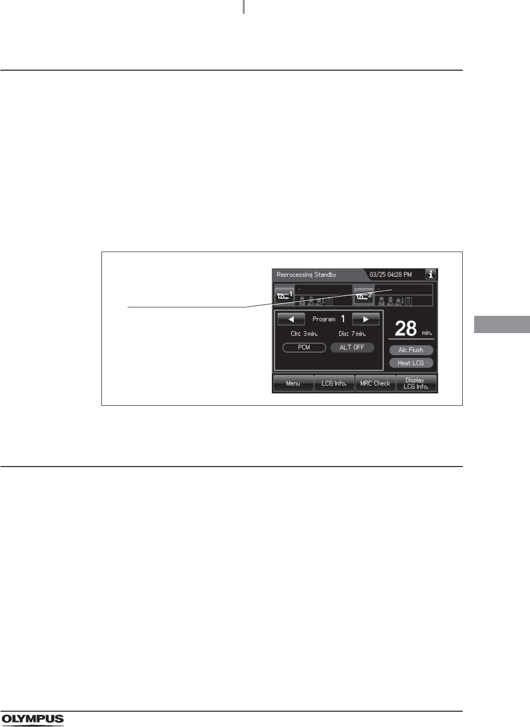
6.6 Loading of endoscopes and accessories
197
OER-Elite OPERATION MANUAL
Ch.6
Input scope ID of second endoscope
To maintain an endoscope reprocessing record, this reprocessor is capable of recognizing the
individual scope ID that identifies the endoscope being reprocessed.
The scope ID can be input with the following methods.
• Input from RFID
• Software keyboard input
• Input from pre-registered information
For details on the input methods, refer to Section 3.6, “Entering ID” (If applicable).
When the scope ID is input, the touch screen displays the model number of the second
endoscope.
Figure 6.34
Loading of second endoscopes in the reprocessing basin
For detail of warning and caution, refer to “Loading of first endoscopes in the reprocessing basin” on
page 166.
Loading of second endoscope in the reprocessing basin
1Confirm the lid is opened. If the lid is closed, step on the foot pedal to open the lid.
2Place the indicator plate of the first AW channel cleaning adapter on the washing case
(if applicable).
Displays the model number
of the second endoscope
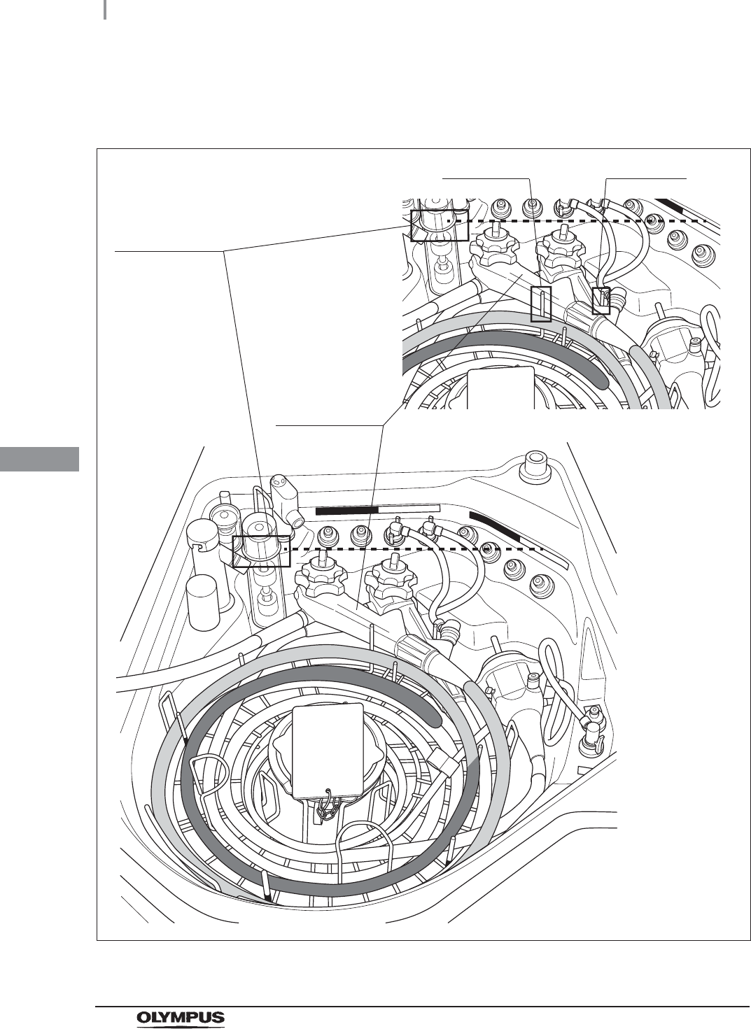
198
6.6 Loading of endoscopes and accessories
OER-Elite OPERATION MANUAL
Ch.6
3Place the control section of the second endoscope on the left of the control section of
the first endoscope between index pin1 and index pin 2. Adjust it to be below the
disinfectant solution level index line indicated in the float sensor protection cover.
Figure 6.35
Index pin 2
Control section
of the second
endoscope
Index pin 1
The disinfectant
solution level
index line
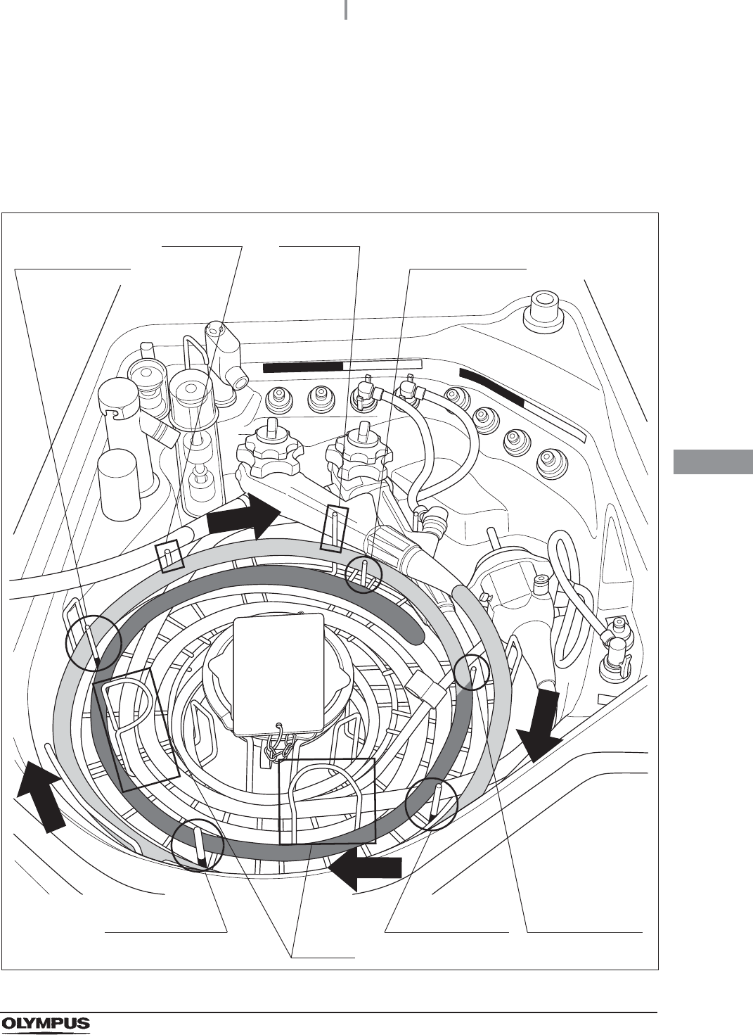
6.6 Loading of endoscopes and accessories
199
OER-Elite OPERATION MANUAL
Ch.6
4Wrap the insertion tube clockwise around the retaining rack from the perimeter in.
Wrap the first turn of the insertion tube outside the black markings from M1 to M5 and
inside the index pin 2 and 3 (shown in light gray).
Wrap the second turn inside the black markings from M1 to M5 and outside the hooks
(shown in dark gray). Refer to Figure 6.36. Do not wrap the insertion tube of second
endoscope on the AW channel cleaning adapters.
Figure 6.36
Black Marking M1
Black Marking M5
Black Marking M3 Black Marking M2
Index pin 2Index pin 3
Black Marking M4
Hooks
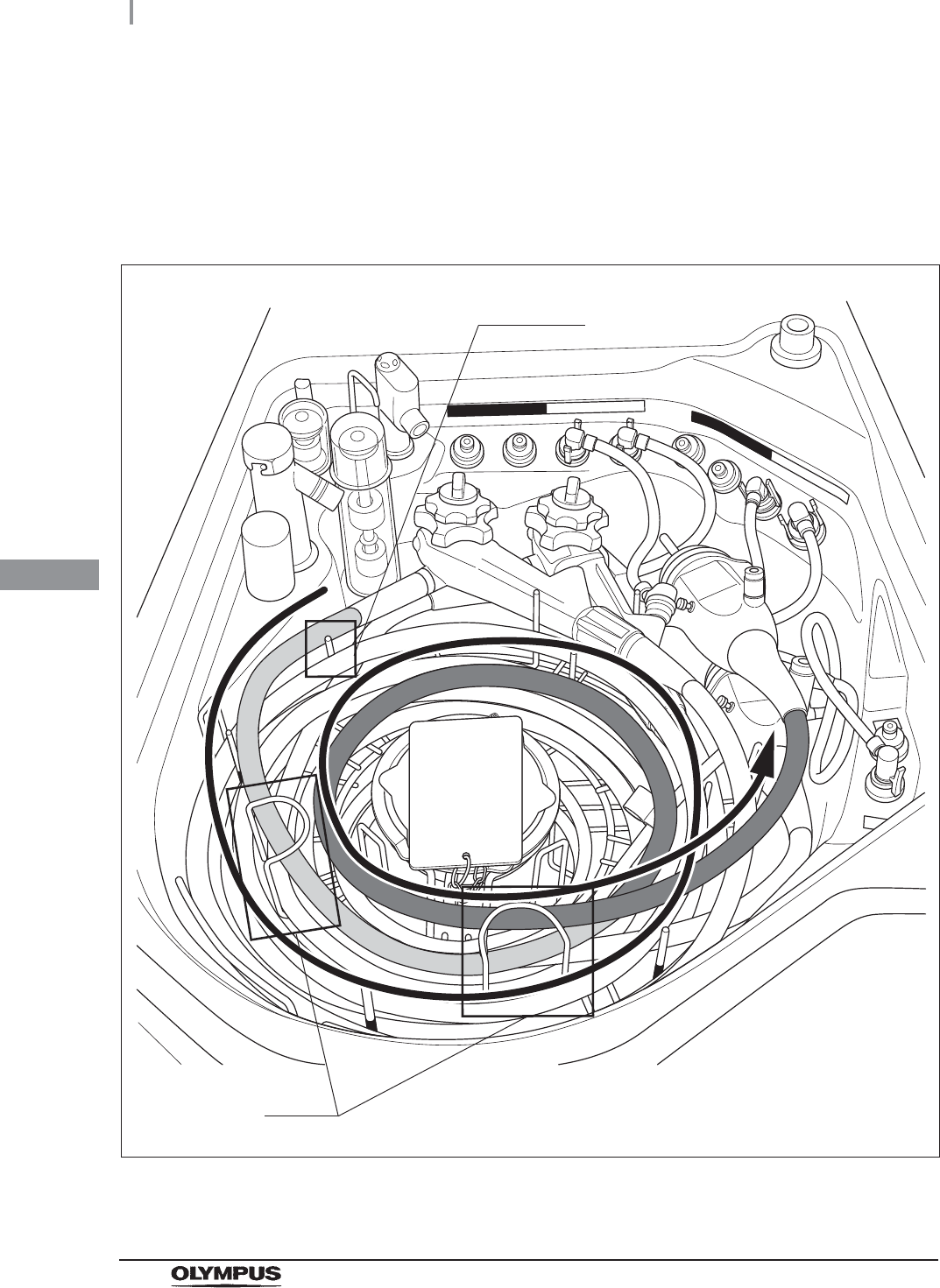
200
6.6 Loading of endoscopes and accessories
OER-Elite OPERATION MANUAL
Ch.6
5Wrap the universal cord (light and deep gray) in a counterclockwise direction on the
left of index pin 3 in the inside section (for detail, refer to the Figure 6.37) on the
retaining rack by placing it under the hooks so that it will not move upward.
If the scope ID tag is attached to the endoscope, move the scope ID tag toward the
endoscope connector. Straighten the ID tag’s band if it is twisted. Do not wrap the
universal cord of second endoscope on the AW channel cleaning adapters.
Figure 6.37
Hooks
Index pin 3
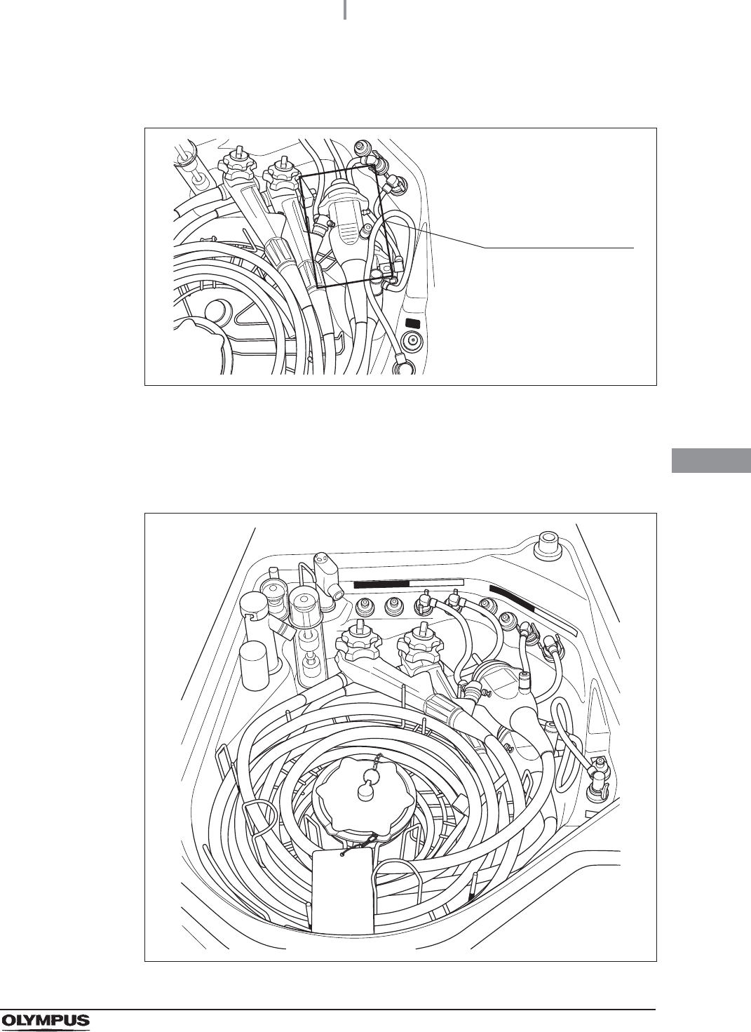
6.6 Loading of endoscopes and accessories
201
OER-Elite OPERATION MANUAL
Ch.6
6Gently place the second endoscope connector on the first endoscope connector as
shown in Figure 6.38.
Figure 6.38
7Adjust the positions of the insertion tube and universal cord to minimize overlapping.
Also, adjust the positioning of the insertion tube’s distal end by turning the angulation
control knobs (lever) on the control section. Again, make sure that the universal cord
is placed on the inside of the hooks.
Figure 6.39
The second endoscope
connector on the first
endoscope connector.
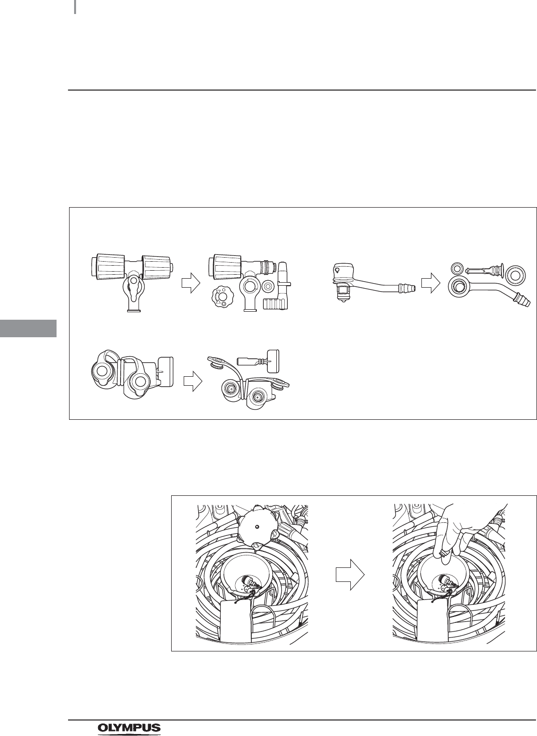
202
6.6 Loading of endoscopes and accessories
OER-Elite OPERATION MANUAL
Ch.6
Loading of the accessories of second endoscope (valves,
etc.)
The valves and specified parts of the endoscopes installed in the reprocessing basin can be
reprocessed in the washing case together with forceps plugs and AW channel cleaning adapters.
For detail of warning and caution, refer to “Loading of the accessories of first endoscope (valves,
etc.)” on page 173.
1Check if the accessories that can be disassembled are disassembled completely.
Figure 6.40
2Open the washing case cover and put the accessories (e.g., biopsy valve, air/water
valve, suction valve, auxiliary water inlet cap) into the washing case. Make sure that
the auxiliary inlet cap is removed from endoscope.
Figure 6.41
Example
Forceps/Irrigation plug (MAJ-891) Suction valve (MAJ-207)
Biopsy valve (MAJ-419)
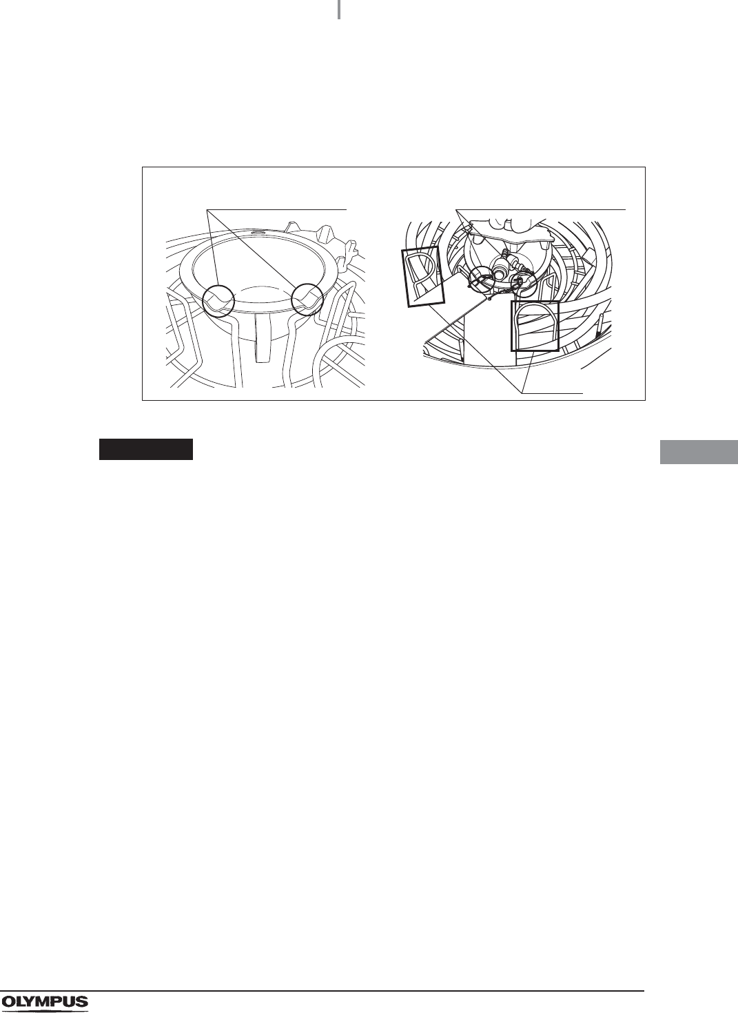
6.6 Loading of endoscopes and accessories
203
OER-Elite OPERATION MANUAL
Ch.6
3Put the AW channel cleaning adapters in the washing case and place the indicator
plates outside the washing case. Ensure the indicator plates is placed between both
hooks. Place the chain of the AW channel cleaning adapter in the designated grooves
on the rim of the washing case.
Figure 6.42
WARNING
• Do not pile up the chain of AW channel cleaning adapter. Otherwise, effectiveness
of the reprocessing of AW channel cleaning adapter may be compromised.
• Do not place three or more AW channel cleaning adapters in the case. Otherwise,
the reprocessing may be insufficient.
• When the chain of AW channel cleaning is set on the rim, make sure that the
indicator plates of AW channel cleaning adapters are set between the hooks by
referring the Figure 6.43 and 6.53. Otherwise, the reprocessing may be
insufficient.
Deep part of the rim of
the washing case.
Chains of the adapter place
on the deep part of the rim.
Hooks
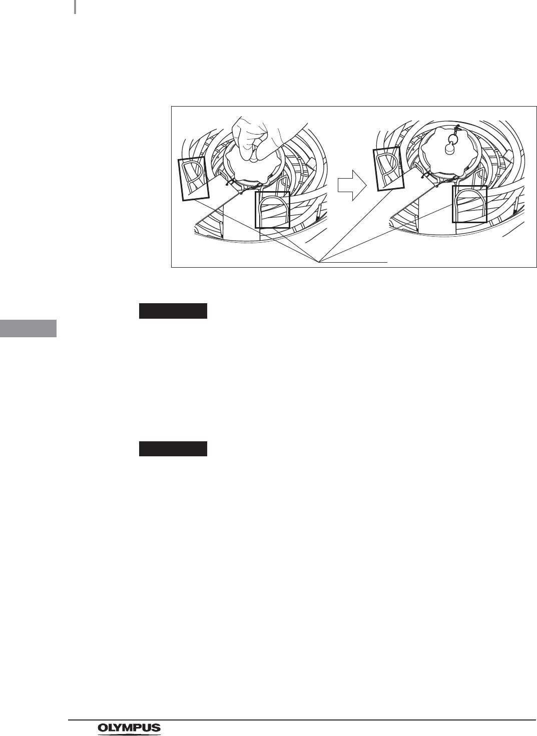
204
6.6 Loading of endoscopes and accessories
OER-Elite OPERATION MANUAL
Ch.6
WARNING
• Do not place endoscope on the indicator plate of AW channel cleaning adapter.
Otherwise, reprocessing of AW channel cleaning adapter may be insufficient.
• The indicator plates of the AW channel cleaning adapters should not be placed in
an area other than specified. Otherwise, the adapters may encounter strong force
when the cover is closed which may cause damage to the endoscopes, AW
channel cleaning adapters, retaining rack and/or lid.
CAUTION
Place the AW channel cleaning adapters in the reprocessing basin so that twisting
or overlapping of the chains of the adapters is minimized. If a chain is twisted or
overlapped excessively, the chain may be caught by the washing case and the
adapter, washing case and/or lid may be damaged.
4Close the washing case cover so that the chains of AW channel cleaning adapter are
not caught between the case and the cover. Ensure the indicator plates of AW
channel cleaning adapter between the hooks.
Figure 6.43
Hooks
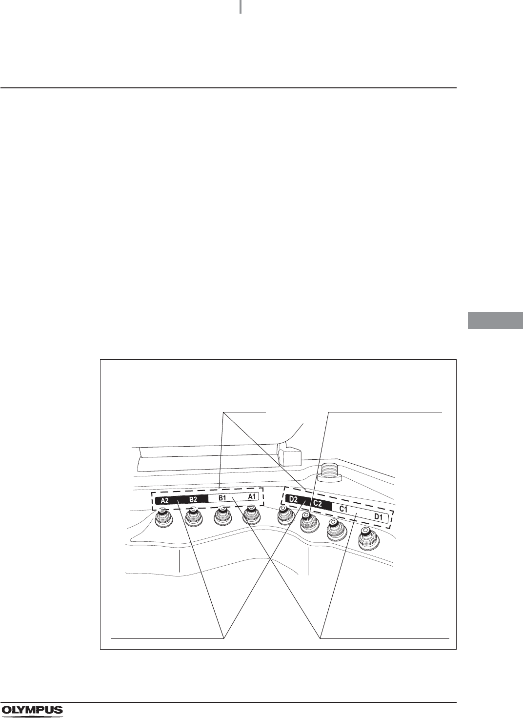
6.6 Loading of endoscopes and accessories
205
OER-Elite OPERATION MANUAL
Ch.6
Attaching the connecting tubes loading to second
endoscope
The OER-Elite is shipped with two sets of four connecting tubes: MAJ-2110, MAJ-2111, MAJ-2112, and
MAJ-2113. Check the “List of Compatible Endoscopes/Connecting Tubes <OER-Elite>” to confirm
whether these connecting tubes are the correct connecting tubes for the particular model endoscope
that you are reprocessing. If the “List of Compatible Endoscopes/Connecting Tubes <OER-Elite>”
indicates that a different connecting tube is required, contact Olympus to obtain the necessary
connecting tube. Each model Olympus endoscope requires a specific connecting tube (or tubes). Do
not attempt to reprocess any endoscope without the correct connecting tube.
For detail of warning and caution, refer to “Attaching the connecting tubes loading to first
endoscope” on page 177.
Labels and color of connector used for the second endoscope
Labels are provided in the reprocessing basin to distinguish each connector. It also provides
information about which connectors are used for the first endoscope and which are used for the
second endoscope.
Each connector has a specified color identical to the color of connecting tubes and leak test air
tubes that can connect to the connector.
Figure 6.44
Color of connector is
identical to the color of
connecting tubes that can
connect to the connector.
White colored label
means this connector is
used in most cases for
first endoscope.
Black colored label
mean this connector is
used in most cases for
second endoscope.
Labels
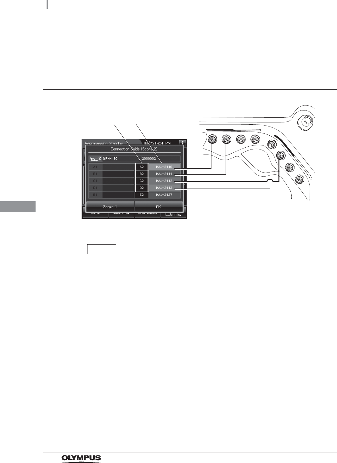
206
6.6 Loading of endoscopes and accessories
OER-Elite OPERATION MANUAL
Ch.6
Connection guide of second endoscope
When connection guide setting is activated, connection guide screen is displayed after inputting
scope ID with RFID.
Connection Guide screen provides the information about the type of connecting tubes required
for the endoscope and the location of connectors that these connecting tubes are connected.
Figure 6.45
NOTE
When the scope ID is input using the master scope ID card or with the manual
input, the Connection Guide screen is not displayed. In this case, connect the
designated connecting tubes by referring to the “List of Compatible
Endoscopes/Connecting Tubes <OER-Elite>”.
Identical colors to
the colors of labels
attached on the
reprocessing basin.
Background colors
identical to the
connector colors.

6.6 Loading of endoscopes and accessories
207
OER-Elite OPERATION MANUAL
Ch.6
Connection of the connecting tubes of second endoscope
The instruction below is compiled assuming the loading of standard-type gastroenterological
endoscopes using standard-set of connecting tubes MAJ-2110, MAJ-2111, MAJ-2112, and
MAJ-2113.
WARNING
• If two endoscopes are reprocessed simultaneously, connect the connecting tube to
the connector in the basin in order of number of the connector (e.g., connector A1
should be connected to the 1st endoscope, connector A2 should be connected to
the 2nd endoscope).
• If connecting tube is connected to the wrong connector, channel blockage
monitoring and channel connectivity monitoring cannot work properly (e.g.,
connecting tube for 1st endoscope is connected to the connector of 2nd
endoscope).
NOTE
If reprocessing a different type of endoscope(s) requires different types of
connecting tubes, refer to the instruction manual for the connecting tube.
1Insert the endoscope side connector of the MAJ-2110 connecting tube all the way into
the suction cylinder and air/water supply cylinder of the endoscope. After each
connector is inserted until it is stopped at the bottom, keep pushing the connector and
slide it toward the eyepiece/remote switch side to secure the connection.
For detail of MAJ-2110, refer to “Attaching the connecting tubes loading to first
endoscope” on Figure 6.13 on page 180.
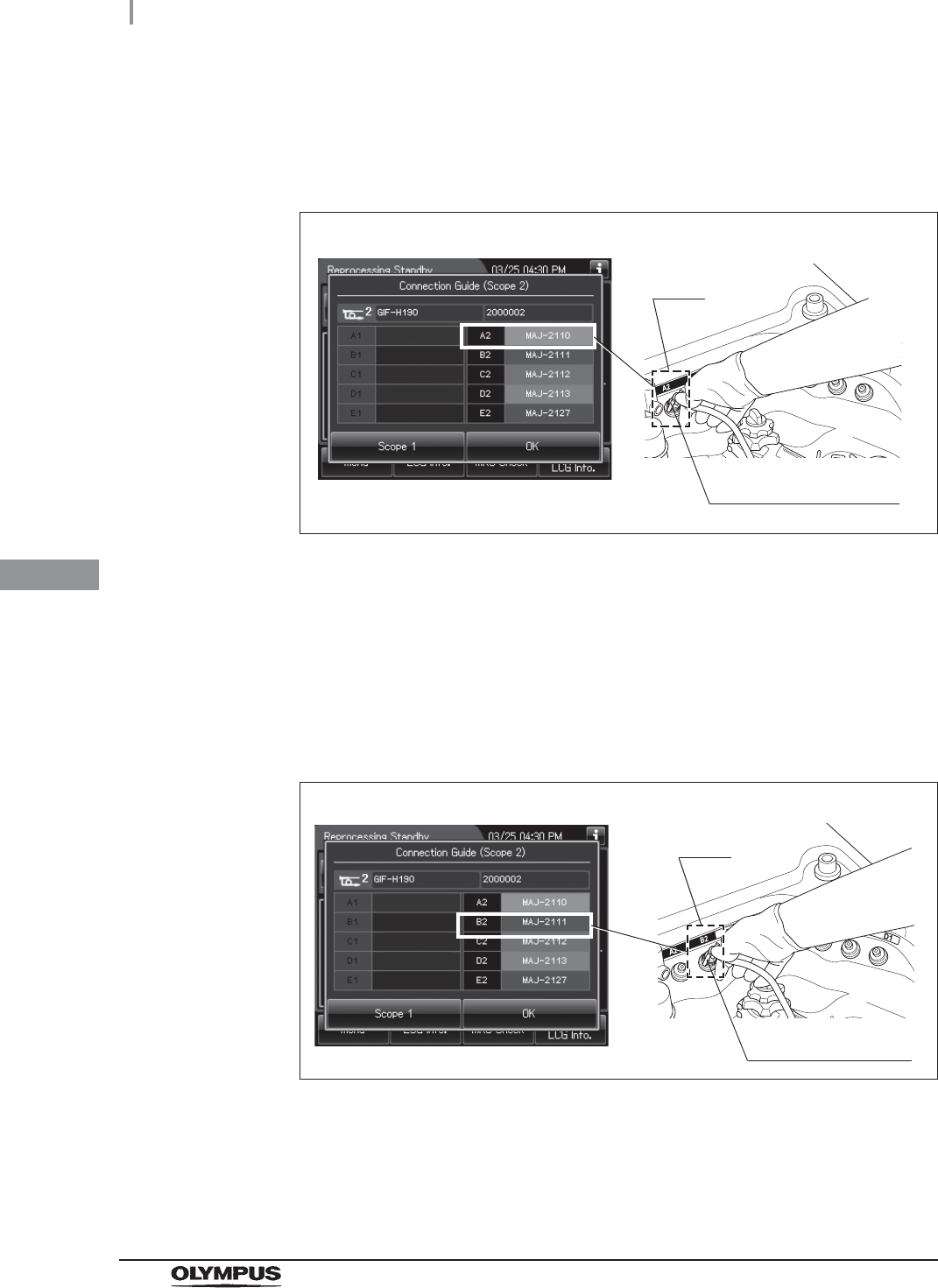
208
6.6 Loading of endoscopes and accessories
OER-Elite OPERATION MANUAL
Ch.6
2Insert the reprocessor-side connector of the MAJ-2110 connecting tube into the
connector with same color (refer to the Connection Guide screen) of the reprocessing
basin by pushing in until it clicks. In this case, connect to the connector A2 for the
second endoscope.
Figure 6.46
3Insert the MAJ-2111 connecting tube into instrument channel port of the endoscope
until it clicks. For detail of MAJ-2111, refer to “Attaching the connecting tubes
loading to first endoscope” on Figure 6.15 on page 181.
4Insert the reprocessor-side connector of the MAJ-2111 connecting tube into the
connector with the same color (refer to the Connection Guide screen) of the
reprocessing basin by pushing in until it clicks. In this case, connect to the connector
B2 for the second endoscope.
Figure 6.47
For second endoscope
A2
Light blue connectors
For second endoscope
Blue connectors
B2
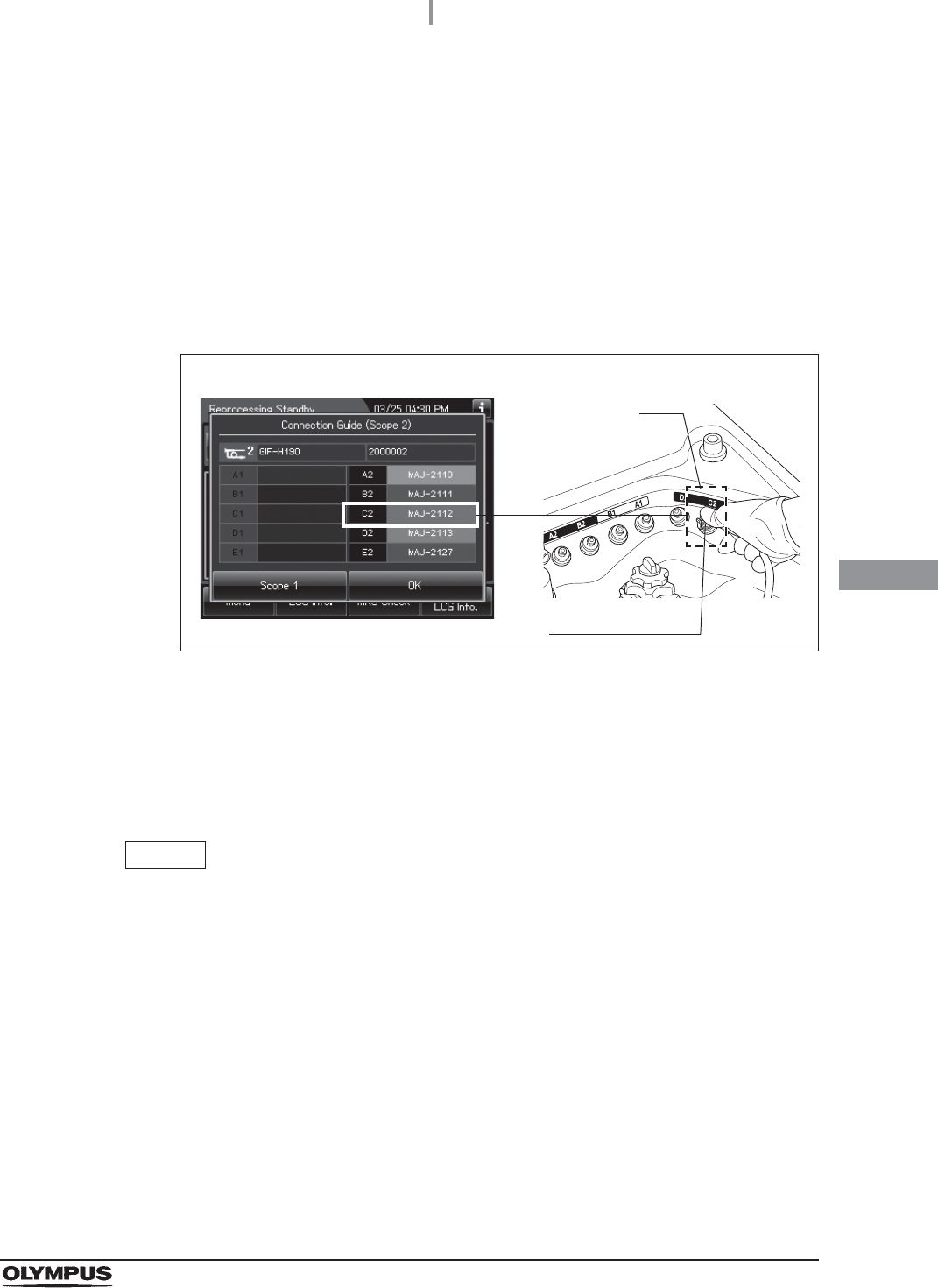
6.6 Loading of endoscopes and accessories
209
OER-Elite OPERATION MANUAL
Ch.6
5Insert the MAJ-2112 connecting tube into the suction connector of the endoscope until
it clicks. For details, refer the Figure 6.45 of “Connection guide of second
endoscope” on page 206.
For detail of MAJ-2112, refer to “Attaching the connecting tubes loading to first
endoscope” on Figure 6.17 on page 182.
6Insert the reprocessor-side connector of the MAJ-2112 connecting tube into
connector with the same color (refer to the Connection Guide screen) of the
reprocessing basin by pushing in until it clicks. In this case, connect to the connector
C2 for the second endoscope.
Figure 6.48
7Insert the MAJ-2113 connecting tube into the auxiliary water port of the endoscope
until it clicks.
For detail of MAJ-2113, refer to “Attaching the connecting tubes loading to first
endoscope” on Figure 6.19. When using the MAJ-2138 refer to “Loading of auxiliary
water tube of first endoscope” on page 186 and Figure 6.21 on page 186.
NOTE
If reprocessing the auxiliary water tube together with the endoscope, optional
MAJ-2138 connecting tube is used instead of MAJ-2113. Also, the auxiliary water
tube cleaning setting should be activated when using optional MAJ-2138
connecting tube. For details on setting, refer to Section 4.16, “Auxiliary water tube
cleaning setting”.
For second endoscope
Green connectors
C2
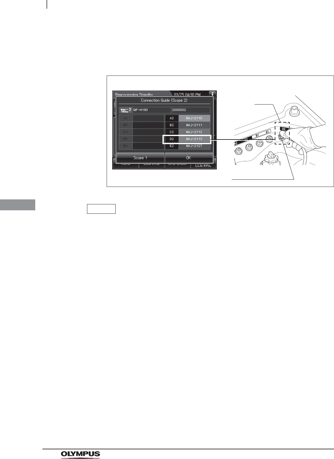
210
6.6 Loading of endoscopes and accessories
OER-Elite OPERATION MANUAL
Ch.6
8Insert the reprocessor-side connector of the MAJ-2113 connecting tube into
connector with the same color (refer to the Connection Guide screen) on the deeper
side of the reprocessing basin by pushing in until it clicks. In this case, connect to the
connector D2 for the second endoscope.
Figure 6.49
NOTE
When reprocessing an endoscope with a forceps elevator, the connecting tube
must be connected to the distal end of the insertion tube.
For the appropriate connecting tube, refer to the “List of Compatible
Endoscope/Connecting Tubes <OER-Elite>”.
For the connection method of the connecting tube, refer to the instruction manual
for the connecting tube.
9If the auto leak test is not included in the reprocessing program, press the OK button
on the touch screen. If the auto leak test is programmed, perform the operation in
“Connection of the leak test air tubes of second endoscope” on page 213.
For second endoscope
D2
Orange connectors
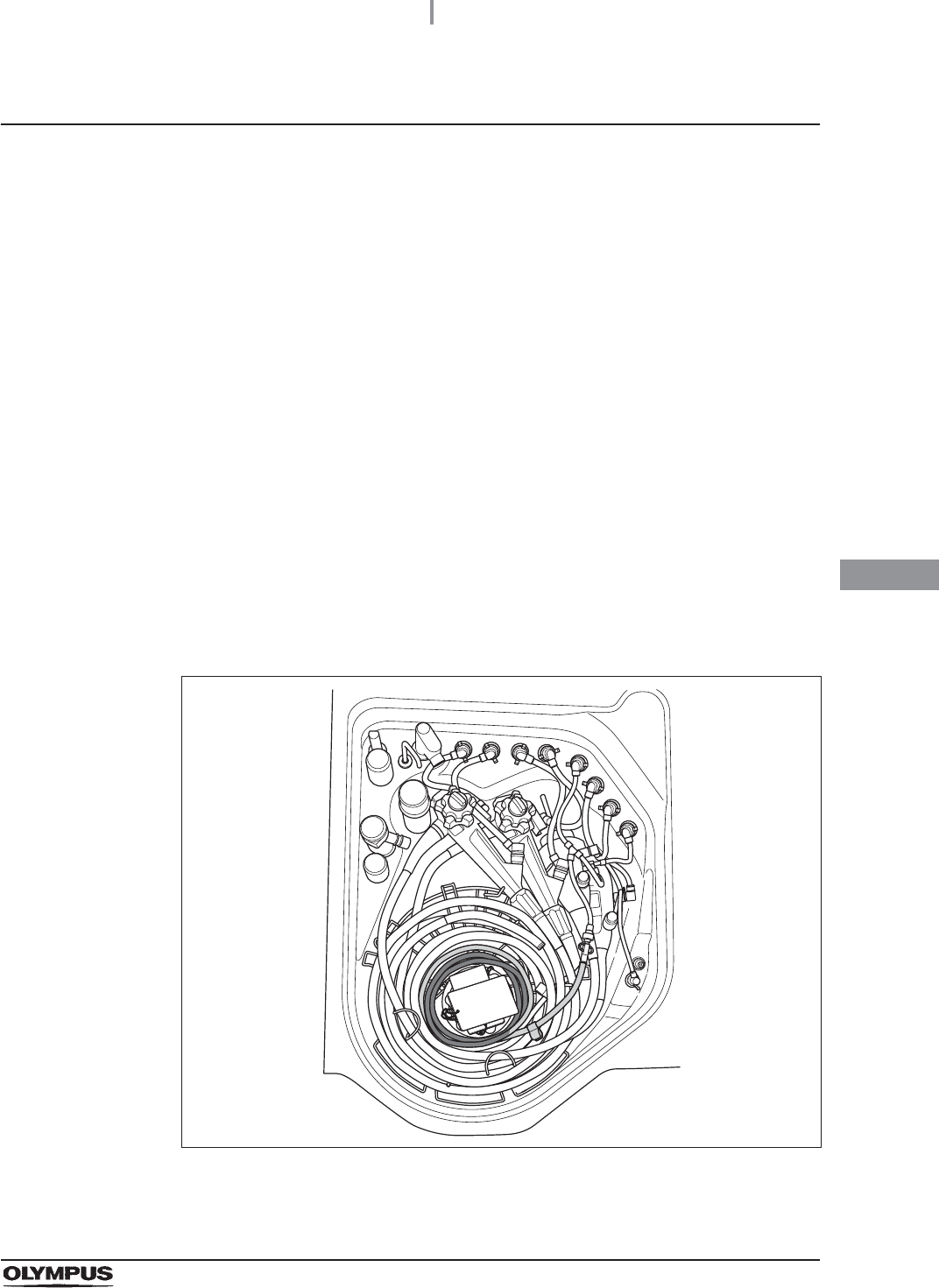
6.6 Loading of endoscopes and accessories
211
OER-Elite OPERATION MANUAL
Ch.6
Loading of auxiliary water tube of second endoscope
When the auxiliary water tube cleaning setting is activated, an endoscope with the auxiliary water
supply function can be reprocessed together with the auxiliary water tube.
For detail of warning and caution, refer to “Loading of auxiliary water tube of first endoscope” on
page 186.
1Insert the endoscope side connector of the MAJ-2138 connecting tube into the
auxiliary water inlet of second endoscope. Turn the outer ring clockwise to connect
firmly. Refer to Figure 6.21 on page 186.
2Insert the auxiliary water tube (MAJ-855) side connector of the MAJ-2138 connecting
tube into the Luer port of the auxiliary water tube. Turn the outer ring clockwise to
connect firmly. Refer to Figure 6.21 on page 186.
3Insert the reprocessor-side connector of the MAJ-2138 connecting tube into the
connector of the same color (refer to the Connection Guide screen) of the
reprocessing basin by pushing in until it clicks.
4Temporarily place the indicator plate of both AW channel cleaning adapters on the
washing case. Wrap the auxiliary water tube clockwise around on the inner section of
the retaining rack. Do not to place the second endoscope and auxiliary water tube on
the indicator plate of the AW channel cleaning adapter.
Figure 6.50
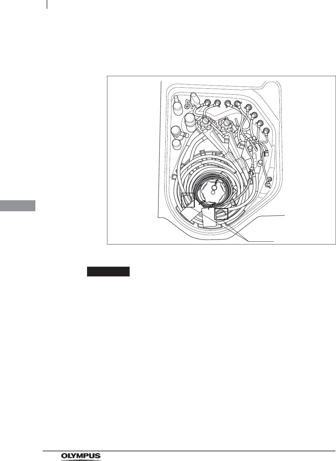
212
6.6 Loading of endoscopes and accessories
OER-Elite OPERATION MANUAL
Ch.6
WARNING
Do not wrap the auxiliary water tube on the AW channel cleaning adapters. If the
auxiliary water tubes are on the plate or the chain of the AW channel cleaning
adapters, the reprocessing of AW channel cleaning adapters may be insufficient.
5After loading the second endoscope and auxiliary water tube, place the indicator
plates of the AW channel cleaning adapter on the second endoscope and auxiliary
water tube. Make sure that the indicator plates of AW channel cleaning adapters are
set between the hooks.
Figure 6.51
Hooks

6.6 Loading of endoscopes and accessories
213
OER-Elite OPERATION MANUAL
Ch.6
Attaching the Leak test air tube loading to second
endoscope
When the auto leak test is included in the reprocessing program, connect the leak test air tube.
For detail of warning and caution, refer to “Attaching the Leak test air tube loading to first
endoscope” on page 189.
Connection of the leak test air tubes of second endoscope
NOTE
• Certain endoscopes are incapable of auto leak test. For the endoscopes which are
compatible with the auto leak test, refer to the “List of Compatible
Endoscopes/Connecting Tubes <OER-Elite>”.
• Do not connect the leak test air tube to the wrong connector (e.g., leak test air tube
for 1st endoscope is connected to the connector for 2nd endoscope). Otherwise,
auto leak testing cannot work properly.
1Wipe the venting connector of the second endoscope or that of the waterproof cap
with a clean cloth immersed in 70% ethyl alcohol or 70% isopropyl alcohol.
2If the leak test connector E2 in the reprocessing basin is wet, remove moisture by
wiping the whole connector with a clean cloth.
3Aligning the groove on the metal connector of the MAJ-2127 leak test air tube with the
pin on the venting connector of the second endoscope or that of the waterproof cap,
insert the connector into the port by turning the connector by 90° in the clockwise
direction while pushing it.
For detail of MAJ-2127, refer to “Connection of the leak test air tubes of first
endoscope” on Figure 6.28 on page 193.
CAUTION
Be sure to connect the leak test air tube to the specified leak test connector in the
reprocessing basin. If auto leak test is performed while the leak test air tube is
connected to a wrong connector, the auto leak test may become incapable of
correct leak detection.
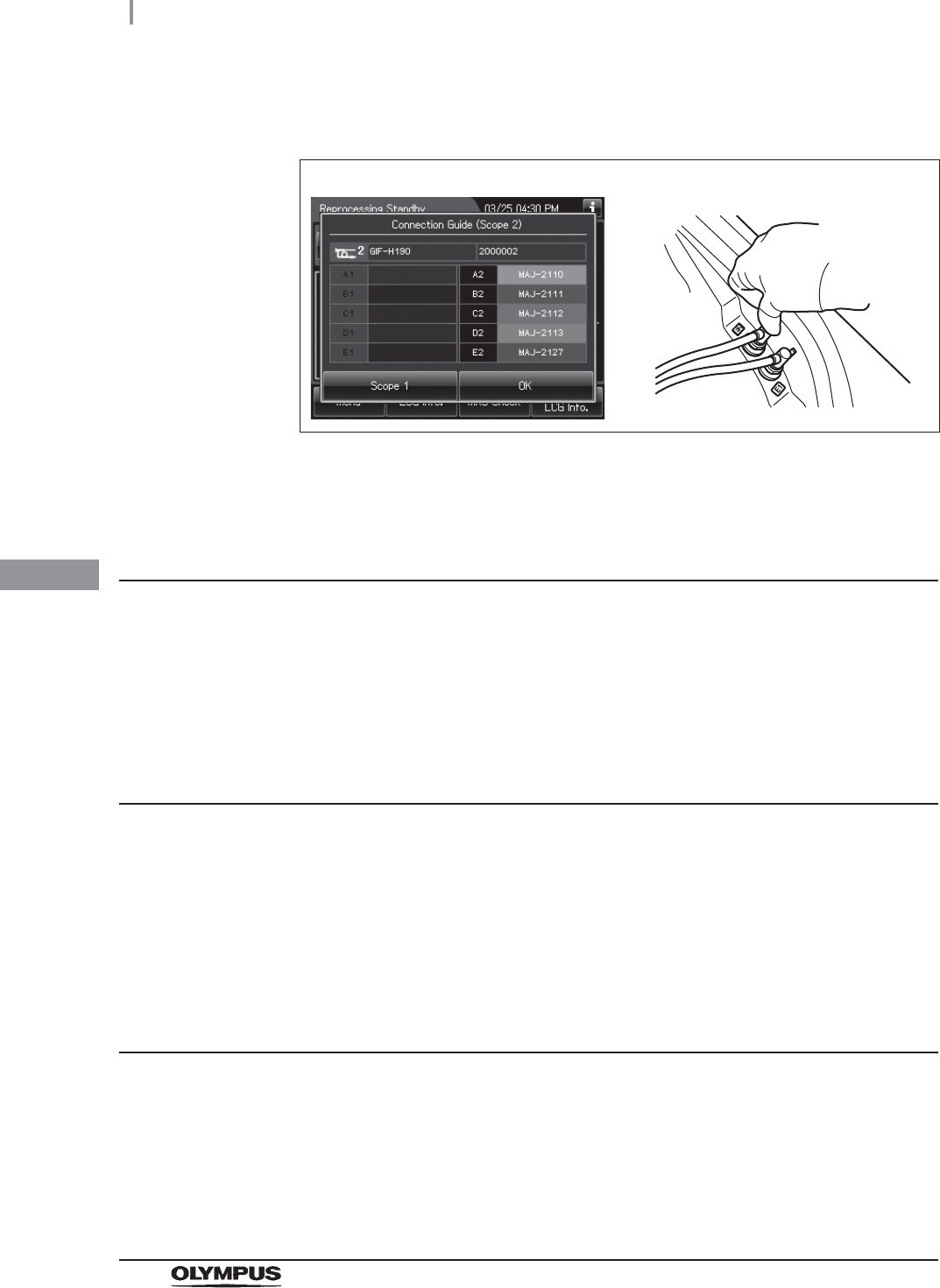
214
6.6 Loading of endoscopes and accessories
OER-Elite OPERATION MANUAL
Ch.6
Input connection information of second endoscope
When the scope ID is entered by method other than RFID, connection information screen described
below is displayed on the touch screen. In this case, input of connection information is required.
For detail, refer to “Input connection information of first endoscope” on page 194.
Input results of manual cleaning and leak test of second
endoscope
When the manual cleaning and leak test setting is activated, result of manual cleaning and leak test
can be entered and associated with the endoscope.
For detail of warning and caution, refer to “Input results of manual cleaning and leak test of first
endoscope” on page 195.
Inputs user ID, physician ID, patient ID, and procedure ID
of second endoscope
User ID (load), physician ID, patient ID, and procedure ID can be entered and associated with the
endoscope. Each ID entry can be changed by settings, refer to Section 4.5 – 4.9. For details on the
input methods, refer to Section 3.6, “Entering ID” (If applicable). When ID is input, the icon of input ID is
displayed with a white icon.
For detail of warning and caution, refer to “Inputs user ID, physician ID, patient ID, and procedure ID
of first endoscope” on page 196.
4Insert the reprocessor-side connector of MAJ-2127 leak test air tube into the
connector E2 until its lock lever is securely engaged with a snap.
Figure 6.52
5Press the “OK” button on the touch screen to close the Connection Guide screen.
Second endoscope
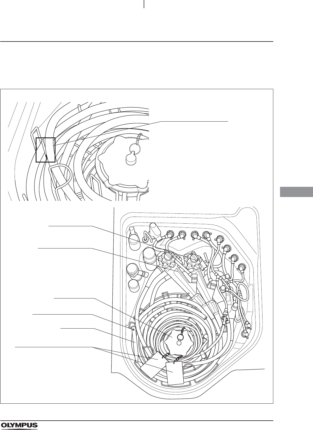
6.6 Loading of endoscopes and accessories
215
OER-Elite OPERATION MANUAL
Ch.6
Loading the stylus pen
The stylus pen can be reprocessed together with the endoscope. When reprocessing the stylus pen,
set the stylus pen by fitting the hole of the stylus pen around the Pin (Black marking M4) of the
retaining rack in the reprocessing basin. Make sure that the indicator plates of AW channel cleaning
adapters are set between the hooks by referring the Figure 6.53.
Figure 6.53
Pin (Black Marking M4)
Stylus pen
Hole of the stylus pen
AW channel cleaning adapter
Washing case
First endoscope
Second endoscope

216
6.7 Inspection before starting reprocessing process
OER-Elite OPERATION MANUAL
Ch.6
Before starting the reprocessing program, be sure to check all descriptions on page149 to page208 to
avoid process interruption and compromise of reprocessing efficacy.
6.7 Inspection before starting reprocessing process
1Check the connections between endoscope and the OER-Elite.
The connecting tubes and leak test air tube are not kinked and bent.
The unnecessary connecting tubes and leak test air tube are not connected to the
OER-Elite.
The wrong connecting tube is not used.
The connecting tube is not connected to the wrong connector in the basin (e.g., connector
B1 should be connected to the 1st endoscope, connector B2 should be connected to the
2nd endoscope).
The connecting tubes should be connected firmly to the connectors.
2Check the washing case.
The cover of the washing case should be closed.
The washing case should be located on the washing case mount.
Any accessories are placed only in the washing case.
The chains of AW channel cleaning adapter are not piled up.
The indicator plate of AW channel cleaning adapter should be located between the hooks.
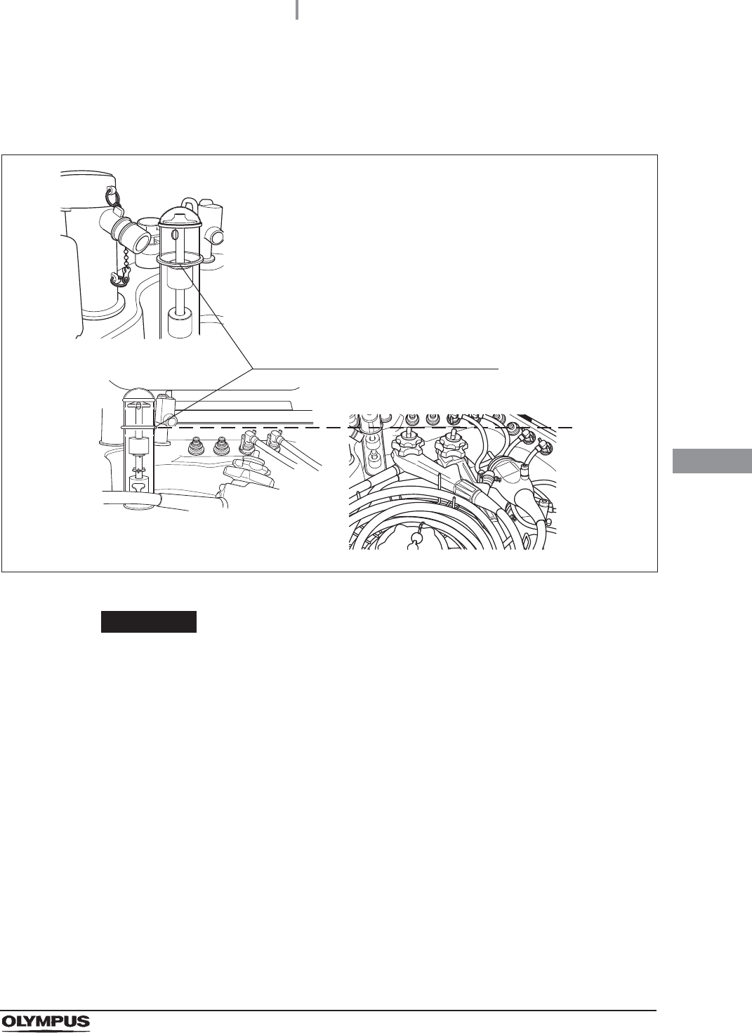
6.7 Inspection before starting reprocessing process
217
OER-Elite OPERATION MANUAL
Ch.6
3Check the endoscopes placed in the reprocessing basin.
The whole of endoscope is installed below the disinfectant solution level index line on the
cover of float switch (long). The cover of float switch (long) should be attached firmly.
Figure 6.54
WARNING
• Be sure to check that the entire endoscope and all accessories are installed below
the disinfectant solution level index line on the cover of float switch (long). If the
endoscope and all accessories are installed above the disinfectant solution level
index line, the reprocessing may be insufficient.
• When reprocessing an endoscope with a forceps elevator, the connecting tube
must be connected to the distal end of the insertion tube. Otherwise, the
reprocessing may be insufficient. For the appropriate connecting tube, refer to the
“List of Compatible Endoscope/Connecting Tubes <OER-Elite>”. For the
connection method of the connecting tube, refer to the instruction manual for the
connecting tube.
4Close the lid by pushing until it clicks and check that any parts of endoscopes do not
touch the lid. Figure 6.55 shows the case of the reprocessing one endoscope. Figure
6.58 shows the case of reprocessing two endoscopes.
Disinfectant solution level index line
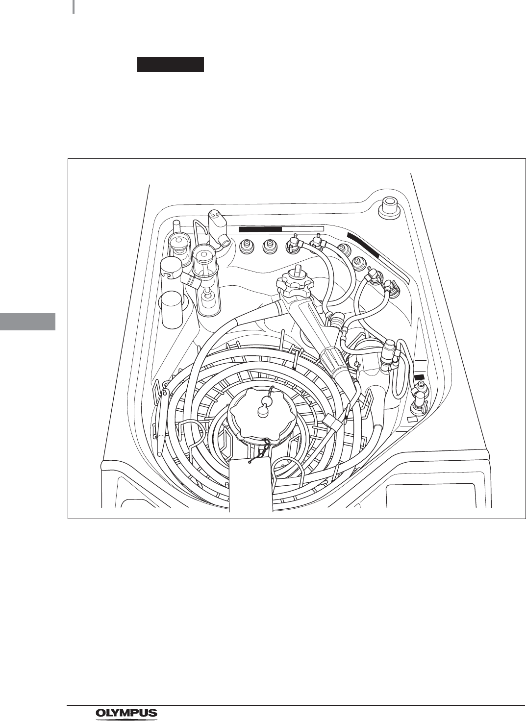
218
6.7 Inspection before starting reprocessing process
OER-Elite OPERATION MANUAL
Ch.6
WARNING
When closing the lid, do not get the connecting tube caught between the
reprocessing basin and lid and make sure the endoscopes and the washing case
are not touching the lid. Otherwise, the endoscopes, the connecting tubes, the
washing case and the reprocessor may be reprocessed insufficiently or get
damaged or water leakage from the reprocessing basin may occur.
Figure 6.55
When reprocessing one endoscope
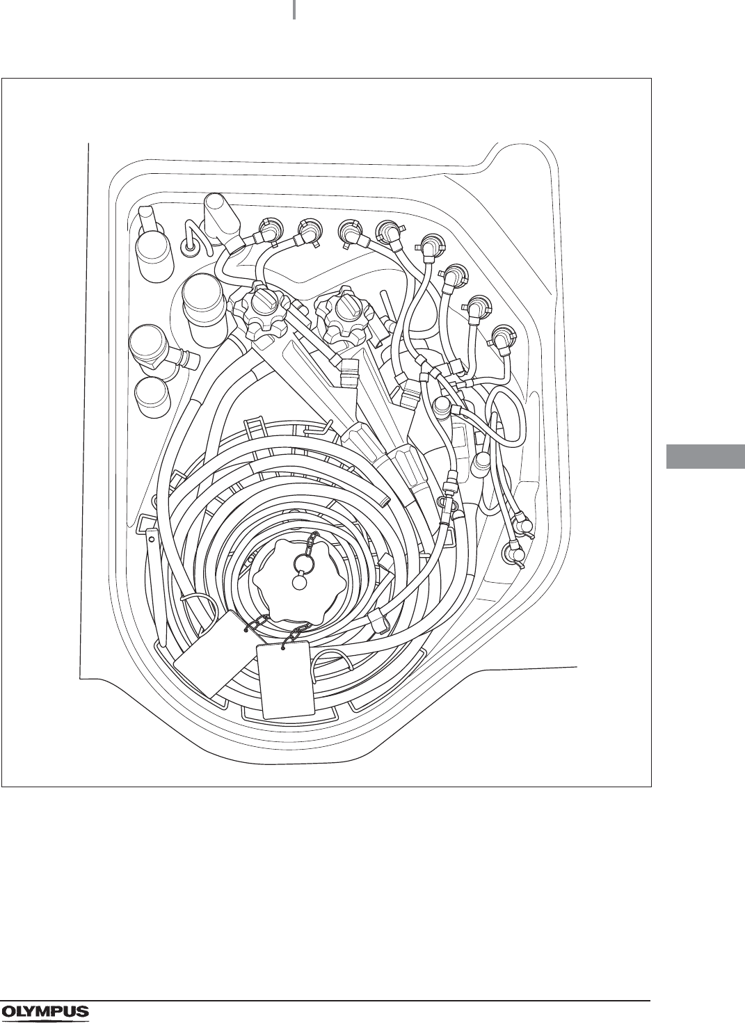
6.7 Inspection before starting reprocessing process
219
OER-Elite OPERATION MANUAL
Ch.6
Figure 6.56
When reprocessing two endoscopes
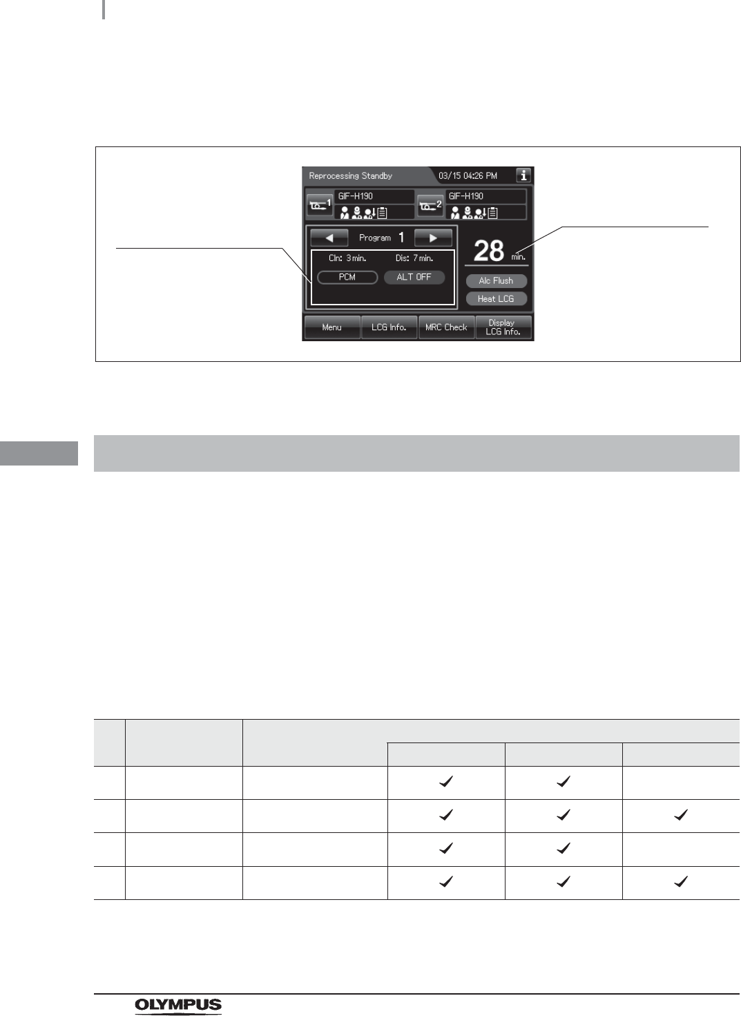
220
6.8 Reprocessing
OER-Elite OPERATION MANUAL
Ch.6
The reprocessing time can be selected from four reprocessing programs [1] to [4]. The auto leak test
and channel monitoring will be performed following the selected reprocessing program.
If any of the following methods are used to input the scope ID, the reprocessing time will be extended
by 3 minutes.
The scope ID master card is used
The scope ID is entered using the software keyboard
The pre-registered scope ID is recalled
Any endoscope with a forceps elevator will take an additional 3 minutes to reprocess.
Table 6.3
5Check the contents of the selected reprocessing program and status of IDs entry.
Confirm that the checking of concentration of disinfectant solution and MRC check
result entry is completed.
Figure 6.57
6.8 Reprocessing
No. Auto leak Test Channel Monitoring (Process that the channel monitoring executes.)
Cleaning Disinfection Rinse
1 OFF Partial (PCM)
2 OFF Full (FCM)
3 ON Partial (PCM)
4 ON Full (FCM)
Process time of
selected reprocessing
program
Contents of the selected
reprocessing program

6.8 Reprocessing
221
OER-Elite OPERATION MANUAL
Ch.6
Auto leak test
This reprocessor can automatically detect a leak in the endoscope during the reprocessing cycle. The
results can be recorded in the reprocessing record. The auto leak test can reduce the mistakes of
manual leak test. In addition to this function, also be sure to perform a leak test before performing
manual cleaning.
Not all endoscopes are capable of auto leak test. For the endoscopes with the auto leak test capability,
refer to the “List of Compatible Endoscopes/Connecting Tubes <OER-Elite>”.
If the scope ID is input by using the scope ID master card, input by the software keyboard or input by
recalling the pre-registered ID, the auto leak test is not available.
The timing of the auto leak test can be selected at the start of reprocessing or at the end of
reprocessing by ALT setting. Refer to Section 6.8, “Reprocessing”.
When the reprocessor detects disconnection of the leak test air tube during the reprocessing process,
it generates error code [E024] and stops the process.
For the related setting changes, refer to Section 4.2, “Auto leak test setting”.
At the start of reprocessing
When warm water is used in manual cleaning, the result of the auto leak test may be
erroneous because the internal pressure of endoscope(s) is unstable due to temperature
change. If the auto leak test is to be performed at the start of reprocessing, begin the
reprocessing process after the endoscope temperature has returned to the room
temperature. To return the room temperature, it takes 15 minutes for endoscopes other
than ultrasonic endoscopes and 30 minutes for ultrasonic endoscopes. When the auto
leak test is performed at the start of reprocessing, the reprocessing time is extended for
about 2 minutes. If leak is detected with an endoscope, follow the procedure for leaking
scope decontamination on it and contact Olympus for servicing. For details on the leaking
scope decontamination, refer to Section 7.15, “Leaking scope decontamination”.
At the end of reprocessing
When the auto leak test is performed at the end of reprocessing, the reprocessing time is
extended for about 2 – 7 minutes depending on the type of endoscopes and the
atmospheric temperature surrounding the reprocessor.
If there is a leak with an endoscope, water may enter the endoscope from the leakage
point.

222
6.8 Reprocessing
OER-Elite OPERATION MANUAL
Ch.6
WARNING
• When water leak is detected with one endoscope, the other endoscope without
water leak might be reprocessed insufficiently. In this case, perform the
reprocessing process again.
• Avoid exposure to direct sunlight or air conditioning vents. If there is drastic
temperature change due to the exposure to direct sunlight or air conditioning, the
leak test result may be erroneous.
• If the leak test result is “Fail”, do not execute reprocessing process. In this case,
perform the leaking scope decontamination process with the leaking endoscope
and contact Olympus for servicing. For details on the leaking scope
decontamination process, refer to Section 7.15, “Leaking scope decontamination”.
CAUTION
• Even if the auto leak test is incorporated in the reprocessing program, be sure to
perform manual leak test before manual cleaning. If water leaks occur with an
endoscope, fluid invasion and damage to the endoscope may occur during manual
cleaning.
• The touch screen may display error code [E114] (Leaked) due to the effect of the
temperature of the endoscope(s). If this happens, execute the auto leak detection
again after the endoscope temperature has returned to the room temperature. If
error code [E114] is displayed again, perform the leaking scope decontamination
process with the leaking endoscope and contact Olympus for servicing. For details
on the leaking scope decontamination, refer to Section 7.15, “Leaking scope
decontamination”.
NOTE
• The covering of the bending section of the endoscope may dilate slightly during the
leak test. This is not malfunction.
• The auto leak test may sometimes be incapable of detecting a very small hole.

6.8 Reprocessing
223
OER-Elite OPERATION MANUAL
Ch.6
Channel monitoring
This reprocessor has the channel monitoring function, which monitors the fluid flow of each endoscope
channel during the reprocessing process and checks clogging of the endoscope’s suction channel
(channel blockage monitoring) and the connection status of the connecting tubes (channel connectivity
monitoring).
The channel monitoring function can detect the following status during the reprocessing process.
Channel blockage monitoring
Complete blocking of the endoscope’s suction channel (stoppage by foreign object or
buckling of suction channel).
NOTE
• Channel blockage monitoring cannot detect a partial blockage of the endoscope's
suction channel.
• The “Channel Blockage Monitoring” is not available for some endoscopes. See
“List of Compatible Endoscopes/Connecting Tubes <OER-Elite>” for the
compatible endoscopes.
• If the scope ID is input by any of the following methods, the Channel blockage
monitoring is not available.
Using the scope ID master card,
Software keyboard.
Recalling the pre-registered ID.
Channel connectivity monitoring
(A) Disconnection of the necessary connecting tube from the connector on the endoscope.
(B) Disconnection of the necessary connecting tube from the connector on the
reprocessing basin.
(C) Connection of the unnecessary connecting tube to the connector on the reprocessing
basin.

224
6.8 Reprocessing
OER-Elite OPERATION MANUAL
Ch.6
NOTE
• Disconnection of the necessary connecting tube from the connector on the
endoscope cannot be detected for some endoscopes. See “List of Compatible
Endoscopes/Connecting Tubes <OER-Elite>” for the compatible endoscopes.
• If the scope ID is input in any of the following methods, the function (A) would not
work.
The scope ID master card is used
The scope ID is entered using the software keyboard
The pre-registered scope ID is recalled
• If a connecting tube is disconnected, the channel blockage monitoring may not
work properly and this reprocessor may detect disconnection of the other
connecting tubes from the connector on the endoscope despite the fact that they
are connected properly.
When the channel monitoring is detected during the reprocessing process, the reprocessor displays
error code [E024] on the touch screen and stops the process.
The detection timings can be selected from “PCM (partial channel monitoring)” for detection in the
cleaning and disinfection processes and “FCM (full channel monitoring)” for detection in the cleaning,
disinfection and rinsing processes. The selected detection timings are recorded in the reprocessing
process record. When “FCM (full channel monitoring)” is selected, the process time extends by about
8 minutes. For the setting change, refer to Section 6.5, “Basic operation for reprocessing”.
CAUTION
The following procedures must be performed. Otherwise, the channel monitoring
may not be able to detect clogged suction channel of the endoscope or improper
connection of the connecting tubes.
Clean the Circulation port mesh filters at the end of every working day.
Check that the connectors on the reprocessing basin are not damaged prior to
every use.
Check that the connecting tubes are not damaged prior to every use.
The endoscope(s) must be placed in the reprocessing basin in accordance with
the instructions in Chapter 6.
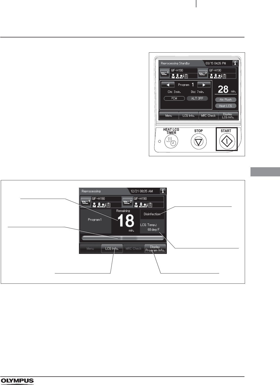
6.8 Reprocessing
225
OER-Elite OPERATION MANUAL
Ch.6
Reprocessing operation
1Press the “START” button. The reprocessing
process starts.
Figure 6.58
2When the reprocessing process starts, the touch screen displays the following.
Figure 6.59
Current process name
Temperature of
disinfectant solution in
reprocessing basin during
disinfection process and
water supply temperature
Remaining time
Process progress bar
Show the detail for
each LCG information
Show the detail for each
program information
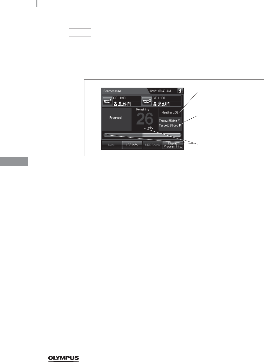
226
6.8 Reprocessing
OER-Elite OPERATION MANUAL
Ch.6
NOTE
• When the disinfectant solution temperature is below 20qC (68qF), it is heated to
20qC (68qF). During heating the disinfectant solution, the remaining time
countdown and progress bar on the touch screen stops and turns gray. The
remaining time countdown restarts after completion of heating the disinfectant
solution.
Figure 6.60
• It takes about 6 minutes to raise the temperature of the disinfectant solution by
1qC.
• To display the remaining time, the reprocessor measures the water supply time at
the first time the reprocessing process. During each reprocessing process, the
reprocessor measures the water flow and correct the remaining time.
Flashes during heating
Temperature of
disinfectant solution in
reprocessing basin
The countdown stops
and turns gray
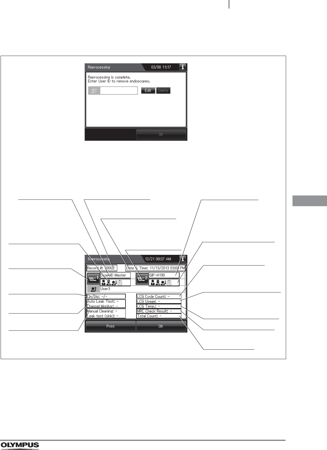
6.8 Reprocessing
227
OER-Elite OPERATION MANUAL
Ch.6
3When reprocessing process is complete, the buzzer beeps and the touch screen
shows the following.
Figure 6.61
When the user ID (remove) setting for
end of reprocessing is activated
When the user ID (remove) setting for
end of reprocessing is disabled
Number given to each
record in the order of
reprocessing
Date and time of completion
of reprocessing
Model number of
reprocessed first
endoscope
Press to check the
ID information
related to the
second endoscope
Model number of
reprocessed second
endoscope
Displays the input status
of patient ID, physician ID,
user ID (remove), and
procedure ID associated
with the second scope
Usage count of the
disinfectant solution
Number of days that have
elapsed since preparation of
the disinfectant solution
Temperature of disinfectant
solution during water line
disinfection
Input result of MRC check
Total count of the
reprocessor
Press to check the ID
information related to
the first endoscope
Displays the input status
of patient ID, physician ID,
user ID (remove), and
procedure ID associated
with the first scope
Cleaning time/
disinfection time
(minutes)
Setting of reprocessing
program
Input results of manual
cleaning and leak test

228
6.9 Removing the endoscopes and accessories
OER-Elite OPERATION MANUAL
Ch.6
This section describes how to take the endoscopes out of the reprocessing basin after disconnecting
the connecting tubes. Also, be sure to remove the valves and other items from the washing case.
WARNING
• If there is an irregularity of the connecting tube on either endoscope, it must be
corrected and both endoscopes must be reprocessed again. Otherwise, the
reprocessing of endoscopes may be insufficient.
• After reprocessing, maintain appropriate transportation and storage procedures to
keep reprocessed endoscopes and accessories away from contaminated
equipment. If the reprocessed endoscope or accessories become contaminated
before subsequent patient procedures, they could pose an infection control risk to
patients and/or operators who touch them.
• Wear sterilized gloves when taking reprocessed endoscopes out of the
reprocessor. Otherwise, the endoscopes may be contaminated and cause
infections. If this happens, you must reprocess the endoscopes again.
• After reprocessing, always confirm that no liquid has leaked from the outside
surface of lid and lid packing.
• Dry the external surface and all channels before storing the endoscope. Otherwise,
miscellaneous bacteria and other sources of contamination may contaminate the
endoscope.
• When taking the endoscopes out of the reprocessor, make sure the endoscopes do
not touch any parts of the reprocessor that has not been disinfected. This may
contaminate the endoscopes. If this happens, you must reprocess the endoscope
again.
CAUTION
Prevent water from getting into the leak test air tube. Otherwise, the endoscope
may be damaged the next time it is used.
NOTE
Disinfectant vapor may still be in the reprocessing basin immediately after the lid is
opened.
6.9 Removing the endoscopes and accessories
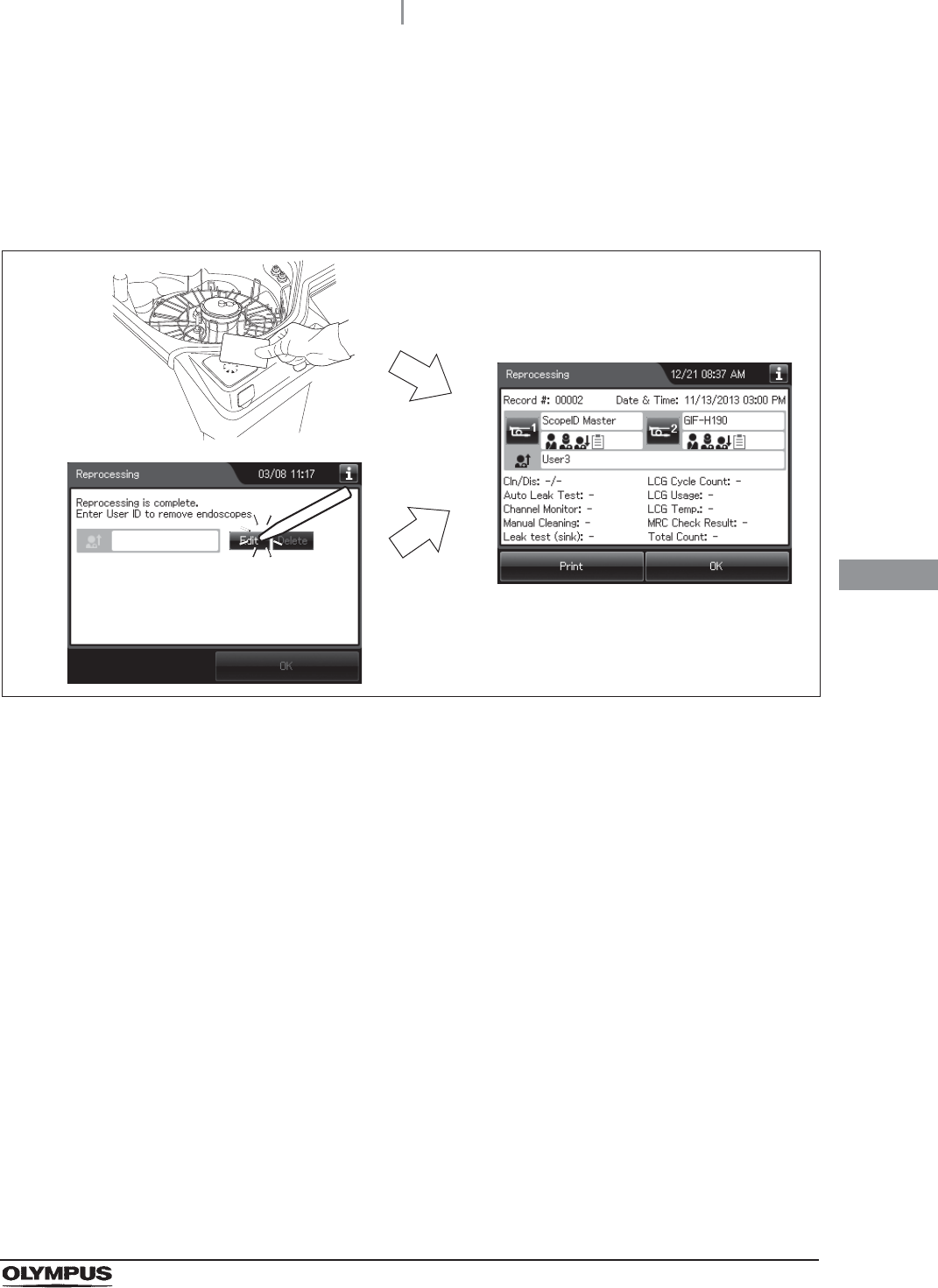
6.9 Removing the endoscopes and accessories
229
OER-Elite OPERATION MANUAL
Ch.6
1When the user ID (remove) setting for end of reprocessing is activated, enter the
operator’s user ID as instructed in Section 3.6, “Entering ID” (If applicable). When the
user ID (remove) is input from the RFID, the touch screen switches to the
Reprocessing Compete screen. When the input is performed manually or from the
previous registration, press the “OK” button to switch the screen.
Figure 6.62
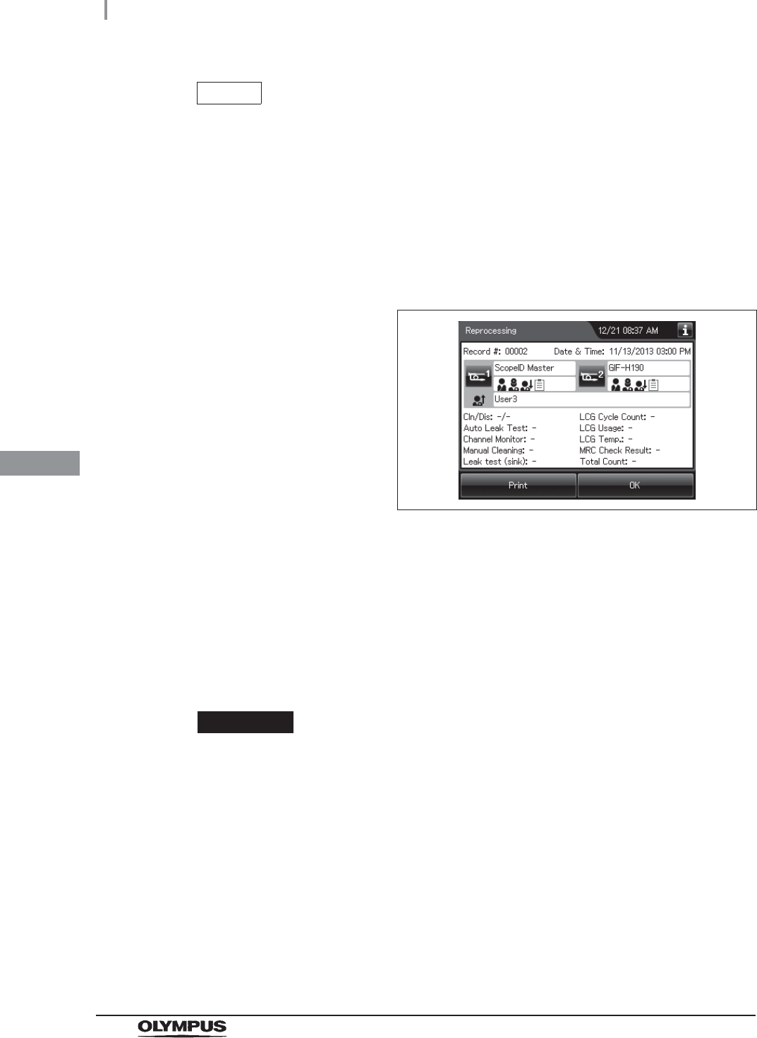
230
6.9 Removing the endoscopes and accessories
OER-Elite OPERATION MANUAL
Ch.6
NOTE
• When the MAJ-1937 printer included in the optional MAJ-2144 printer set is
connected and the auto print setting is activated, the result of reprocessing is
printed automatically. To set the auto print setting, refer to Section 4.17, “Print
option”.
• To print the result of reprocessing, press the “Print” button.
• The lid is locked until user ID (remove) entry is completed.
• When the user ID (remove) setting for end of reprocessing is disabled, completion
screen is displayed after the reprocessing is complete.
Figure 6.63
2Wear a face mask, gloves, and protective clothes. Step on the foot pedal to open the
lid.
3Check the condition of the connecting tubes.
The connecting tubes should not be bent.
The connecting tubes should be connected firmly to the connectors.
The connecting tubes should be free of irregularities including cracks, scratches, etc.
WARNING
Before disconnecting a connecting tube, visually confirm that there are no
irregularities such as kinking, accidental detachment or use of wrong connecting
tube and confirm that each connecting tube is firmly attached. If any irregularity is
observed, it must be corrected and the endoscope must be reprocessed again.
Otherwise, the reprocessing may be insufficient.

6.9 Removing the endoscopes and accessories
231
OER-Elite OPERATION MANUAL
Ch.6
NOTE
If the connecting tube is connected to the wrong connector in the reprocessing
basin (e.g. a connecting tube for the 1st endoscope is connected to the connector
for the 2nd endoscope), the endoscope does not have to be reprocessed again.
4Take out the stylus pen from the reprocessing basin.
5Take out the accessories from the washing case.
6If using the auxiliary water tube (MAJ-855/MAJ-2021), disconnect and take out the
auxiliary water tubes (MAJ-855/MAJ-2021) from connecting tube MAJ-2138.
7Disconnect and take out all connecting tubes and leak test air tubes from each
endoscope and reprocessor.
8Take out the endoscope(s) from the reprocessing basin. When taking out the
endoscope(s), make sure the endoscopes do not touch any parts of the reprocessor
that have not been disinfected.
9Wipe off any water on the endoscopes using a piece of sterile gauze.
10 If the endoscopes have the auxiliary water inlet, attach the auxiliary water inlet cap to
the auxiliary water inlet.
WARNING
After reprocessing, maintain appropriate transportation and storage procedures to
keep reprocessed endoscopes and accessories away from contaminated
equipment. If the reprocessed endoscope or accessories become contaminated
before subsequent patient procedures, they could pose an infection control risk to
patients and/or operators who touch them.
11 According to the endoscope’s instruction manual, store the endoscopes and valves in
a clean place.
12 Take the connecting tubes and leak test air tubes out of the reprocessing basin, wipe
off any water on the tubes using a piece of sterile gauze, and store them in a clean
place.
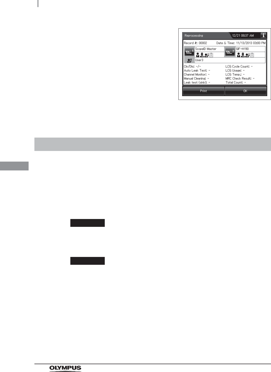
232
6.10 Printing of the reprocessing records
OER-Elite OPERATION MANUAL
Ch.6
When the MAJ-1937 printer included in the optional MAJ-2144 printer set is connected to this
reprocessor, the results of reprocessing and the information on the error code, if generated, after the
completion of reprocessing.
For how to install the printer set, refer to Section 3.11, “Loading of the optional accessories” in
“Instructions-Installation Manual” and to the instruction manual for the printer set.
Auto printing after the end of reprocessing or in the case of error generation is possible by a setting
change. For the setting change method, refer to Section 4.17, “Print option”.
WARNING
Do not touch the thermal head or its surroundings immediately after printing. They
will be very hot and cause burns.
CAUTION
• The printed information does not guarantee the reprocessing of endoscopes. Use
the printed sheets as a record of the reprocessor’s operations.
• Printed data may be lost as the paper ages and deteriorates. If you want to store
this information for a month or more, transfer it to a medium with long-term storage
capability.
• To prevent printer failure or printer paper roll discoloration, do not touch the printer
or printer paper roll with wet hands.
• To prevent the printer from malfunctioning, do not moisten it or printer paper roll.
• Be sure to attach the printer hood. Otherwise, the printer and/or printer paper roll
may get wet and cause a malfunction.
13 Press the “OK” button.
Figure 6.64
14 Reprocessed endoscopes are now ready for use.
6.10 Printing of the reprocessing records

6.10 Printing of the reprocessing records
233
OER-Elite OPERATION MANUAL
Ch.6
CAUTION
• To avoid damage to or deterioration of the printout, do not allow the paper to make
contact with the following:
Alcohol or detergent
Oil, fat, organic solvents, or chemicals (medical, industrial or cosmetic)
Stamp ink
Water
Materials containing plasticizer (PVC film, desk mat, leather products, journal
cover, etc.)
Certain stationery (plastic tape, mending tape, fluorescent-ink pen, oil-ink pen,
adhesives other than starchy paste)
• To prevent discoloration of unused paper, store unused printer paper rolls
according to the following conditions.
Dark, cool place
Not to exceed 25qC (77qF)
Not to exceed 65%RH
Not exposed to NOx (nitrogen oxide(s)), SOx (sulfur oxide(s)), or O3 (ozone)
• To prevent discoloration of paper after printing, store it in a place of the following
conditions. If it is required to store the printed results for a month or more, it is
recommended to copy the information printed on the paper to durable sheets and
store the copies.
Dark, cool place
Not exceed 25qC (77qF)
Not exceed 65%RH
Not exposed to NOx (nitrogen oxide(s)), SOx (sulfur oxide(s)), or O3 (ozone)
• When red lines appear on both sides of the printer paper roll during printing,
replace the printer paper roll.
• Do not touch the paper cutter of the printer when cutting the printed paper.
Otherwise, it may injure your hand.
• Cut the printed paper after every printing. Otherwise, the printer paper roll may jam
and/or be damaged.
• Pay attention to handle the portable memory and printed paper that include patient
information exported from the OER-Elite.
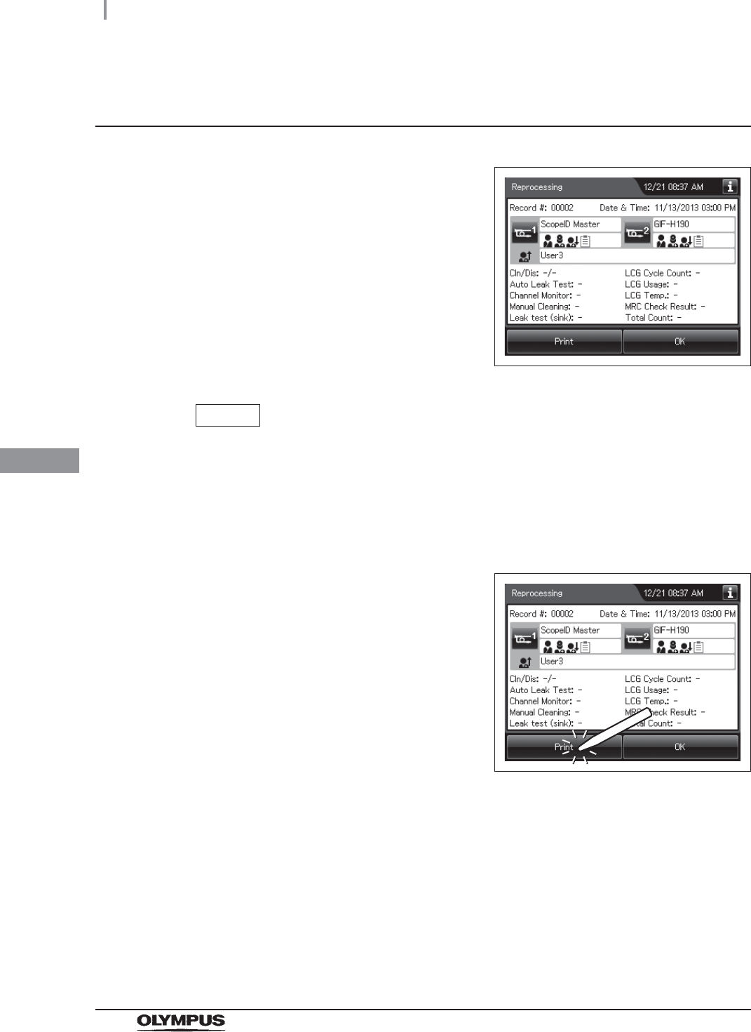
234
6.10 Printing of the reprocessing records
OER-Elite OPERATION MANUAL
Ch.6
Printing reprocessing results after completion of
reprocessing
Print format (reprocessing result)
The reprocessing result is printed in the following 2 options. To change the option, refer to
Section 4.17, “Print option”.
1After completion of the reprocessing process,
ensure that the following screen is shown on
the touch screen.
Figure 6.65
NOTE
If the “OK” button is pressed here, the touch screen switches to the Reprocessing
Standby screen. If the Reprocessing Standby screen appears, select “Log, Info”
from the menu to open the screen of each record and press the “Print” button to
start printing. For how to view a record, refer to Section 11.2, “Log display and
output”.
2Press the “Print” button.
Figure 6.66
3A buzzer beep and stopping of paper feed mean that the printing is complete. Cut the
printed paper and ensure that the required information is printed correctly.
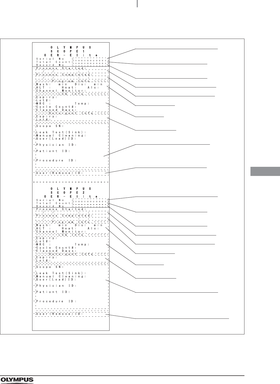
6.10 Printing of the reprocessing records
235
OER-Elite OPERATION MANUAL
Ch.6
(a) Separate
Figure 6.67
Serial number of this reprocessor
Date and time of start of process
Date and time of end of process
Information of first endoscope
User ID (remove) of the end of
process of first endoscope
Total accumulated of
reprocessing process count
Number given to each record
in the order of occurrence
Setting details
LCG Info.
Detergent Info.
Serial number of this reprocessor
Date and time of start of process
Date and time of end of process
Information of second endoscope
User ID (remove) of the end of process
Total accumulated of
reprocessing process count
Number given to each record
in the order of occurrence
Setting details
LCG Info.
Detergent Info.
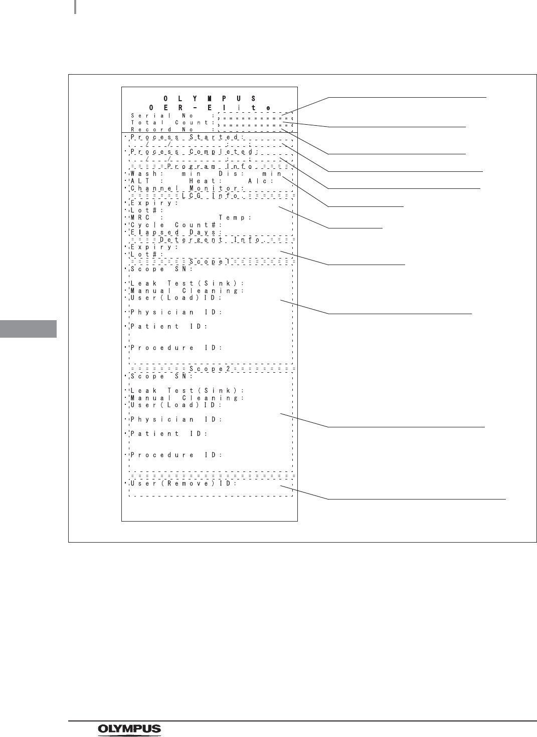
236
6.10 Printing of the reprocessing records
OER-Elite OPERATION MANUAL
Ch.6
(b) Combine
Figure 6.68
Serial number of this reprocessor
Date and time of start of process
Date and time of end of process
Total accumulated of
reprocessing process count
Number given to each record
in the order of occurrence
Setting details
LCG Info.
Detergent Info.
Information of first endoscope
Information of second endoscope
User ID (remove) of the end of process
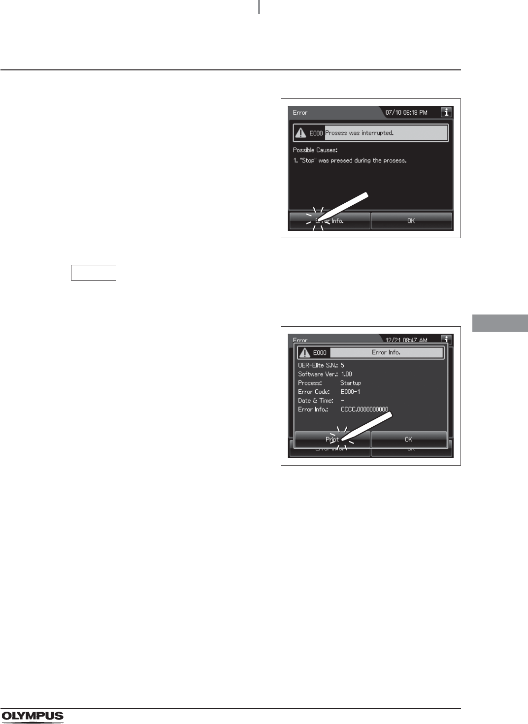
6.10 Printing of the reprocessing records
237
OER-Elite OPERATION MANUAL
Ch.6
Printing error code details in case of error
1The following screen appears after auto
processing of a generated error. On this
screen, press the “Error Info.” button.
Figure 6.69
NOTE
The displayed information varies depending on the generated error.
2Press the “Print” button.
Figure 6.70
3A buzzer beep and stopping of paper feed mean that the printing is complete. Cut the
printed paper and ensure that the required information is printed correctly.
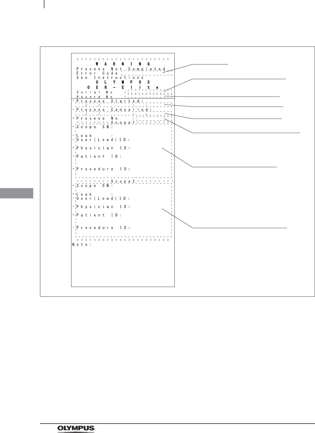
238
6.10 Printing of the reprocessing records
OER-Elite OPERATION MANUAL
Ch.6
Print format (error result)
Figure 6.71
Serial number of this reprocessor
Date and time of start of process
Date and time of end of process
Process number of occurrence of error
Information of first endoscope
Error code
Number given to each record in
the order of occurrence
Information of second endoscope

7.1 Function menu
239
OER-Elite OPERATION MANUAL
Ch.7
Chapter 7 Functions
Function menu
This menu is composed of two pages. To go between the pages, press the next page button or
previous page button.
NOTE
To set the Heat LCG Timer, press the “HEAT LCG TIMER” button on the control
panel. For details, refer to Section 7.3, “Heat LCG Timer”.
7.1 Function menu
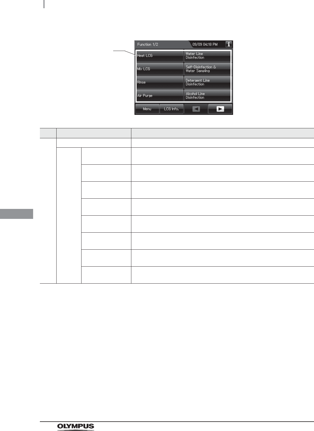
240
7.1 Function menu
OER-Elite OPERATION MANUAL
Ch.7
No. Button Description
1 Function item button Press to display the buttons for starting various functions.
Page 1 Heat LCG Press to heat the disinfectant solution.
oRefer to Section 7.2, “Heat LCG”.
Mix LCG Press to mix the disinfectant solution.
oRefer to Section 7.4, “Mix LCG”.
Rinse Press to rinse the disinfected articles.
oRefer to Section 7.5, “Rinse”.
Air Purge Press to perform air purge.
oRefer to Section 7.6, “Air purge”.
Water Line
Disinfection
Press to disinfect the water supply line.
oRefer to Section 7.7, “Water line disinfection”.
Self-Disinfection &
Water Sampling
Press to perform self-disinfection.
oRefer to Section 7.8, “Self-disinfection and water sampling”.
Detergent Line
Disinfection
Press to disinfect the detergent line.
oRefer to Section 7.9, “Detergent line disinfection”.
Alcohol Line
Disinfection
Press to disinfect the alcohol line.
oRefer to Section 7.10, “Alcohol line disinfection”.
1
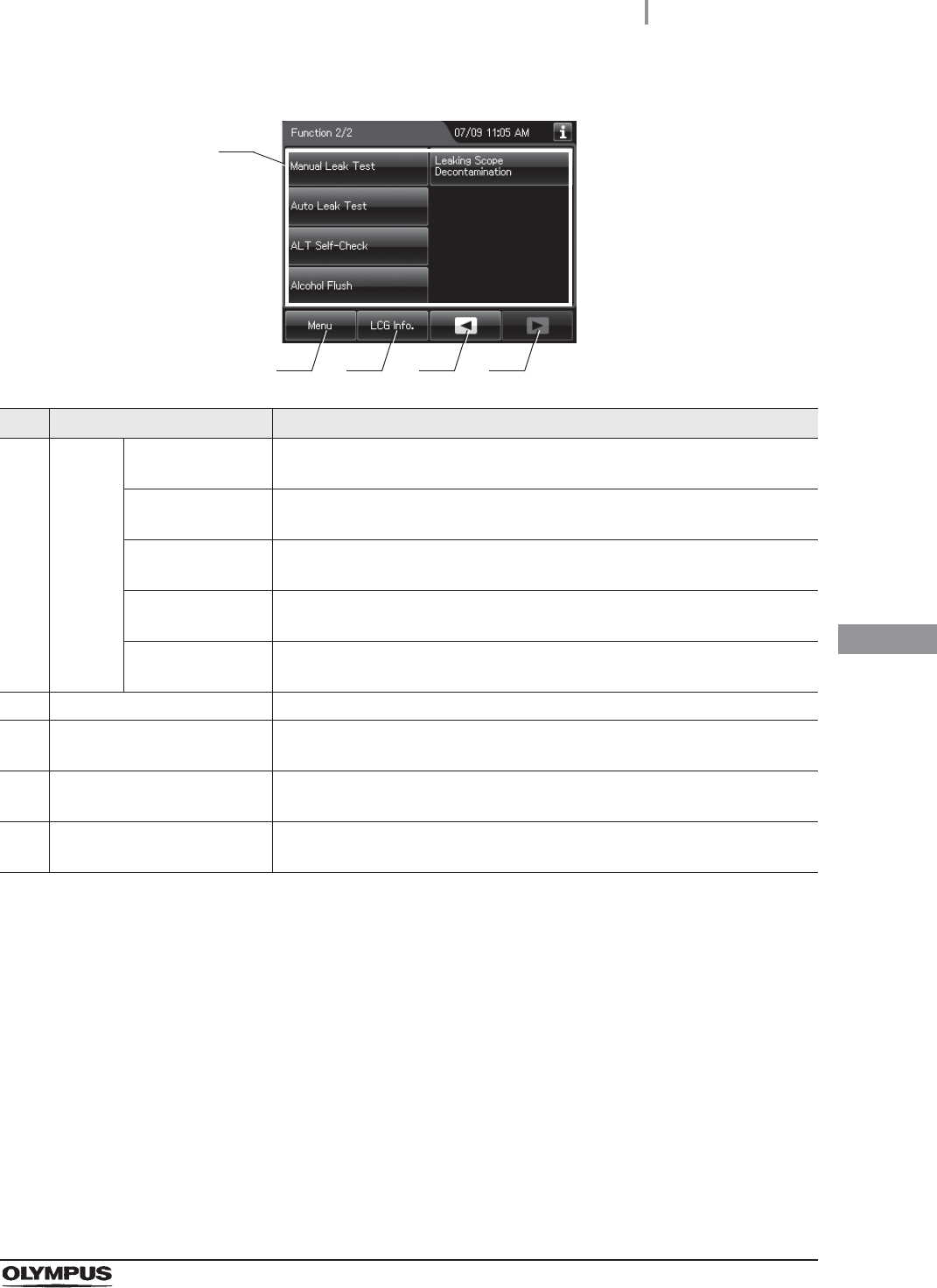
7.1 Function menu
241
OER-Elite OPERATION MANUAL
Ch.7
No. Button Description
1 Page 2 Manual Leak Test Press to perform manual leak test.
oRefer to Section 7.11, “Manual leak test”.
Auto Leak Test Press to perform the auto leak test.
oRefer to Section 7.12, “Auto leak test”.
ALT Self-Check Press to perform the self-check of the auto leak test function.
oRefer to Section 7.13, “Self-check of auto leak test”.
Alcohol Flush Press to perform alcohol flush.
oRefer to Section 7.14, “Alcohol flush”.
Leaking Scope
Decontamination
Press to perform the leaking scope decontamination.
oRefer to Section 7.15, “Leaking scope decontamination”.
2 Menu button Press to open the Menu screen.
3 LCG Info. button Press to open the LCG Info. screen.
oRefer to Section 3.5, “LCG Info. screen”.
4 Previous page button Press to return to the previous page. When there is no further page to go
forward to, the button turns gray and becomes unavailable.
5 Next page button Press to go to the next page. When there is no further page to turn back to,
the button turns gray and becomes unavailable.
1
2 3 4 5
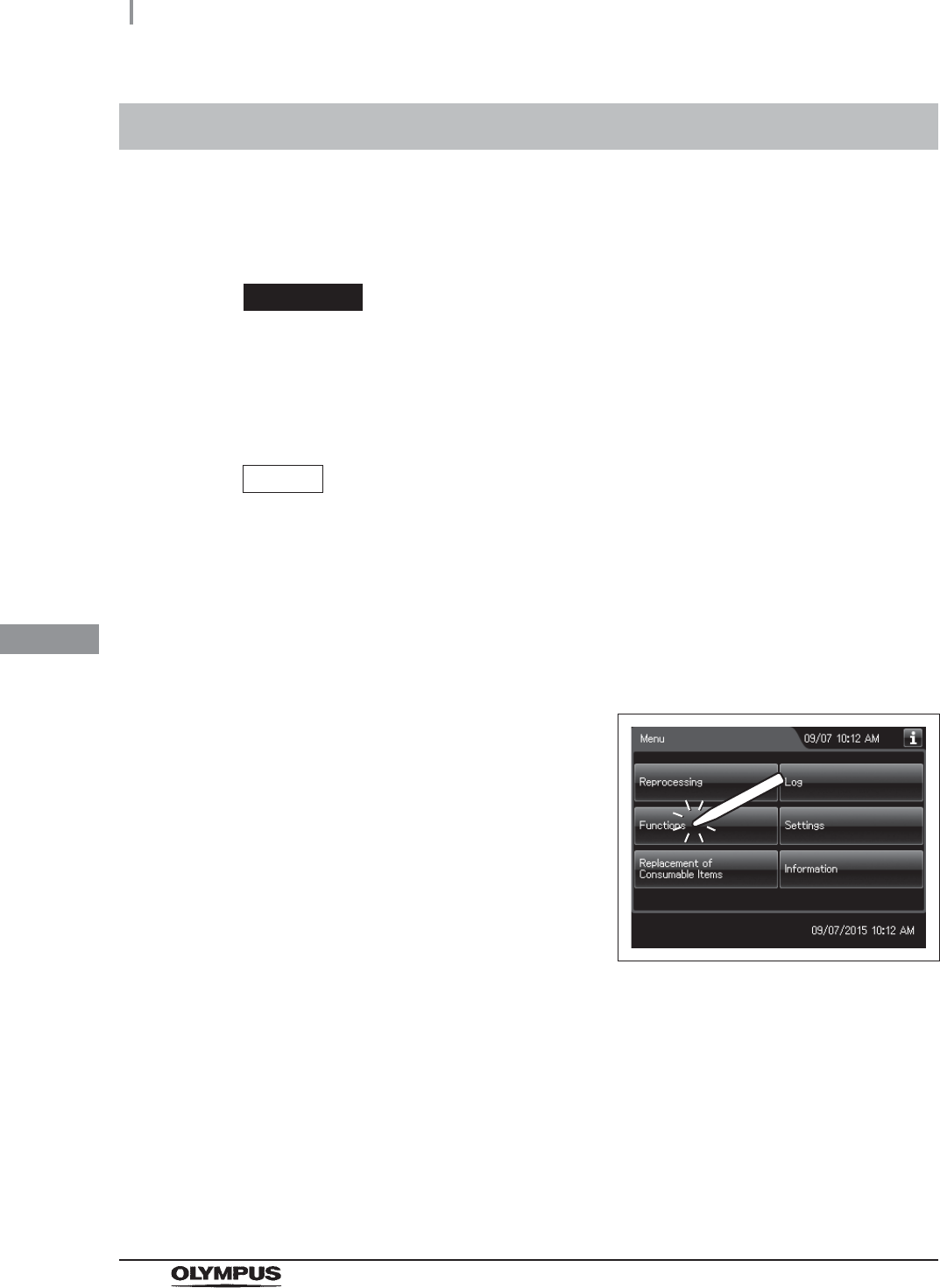
242
7.2 Heat LCG
OER-Elite OPERATION MANUAL
Ch.7
This section explains how to heat the disinfectant solution independently of the reprocessing
programs. The operation consists of heating disinfectant solution to 22qC (72qF) when the disinfectant
solution temperature is below 20qC (68qF).
CAUTION
Before starting heating the disinfectant solution, always confirm that there is no
foreign material on the ventilation openings on the gas filter cases. Blocking the
ventilation not only hinders deodorization but may also cause the reprocessor to
malfunction.
NOTE
• Before performing the Heat LCG, disconnect the leak test air tube from the
connector on the reprocessor and take the tube out of the reprocessing basin. If
leak test air tubes are left in the basin, it becomes wet through the Heat LCG
process.
• For how to check the disinfectant solution temperature, refer to Section 3.5, “LCG
Info. screen”.
7.2 Heat LCG
1Press the “Functions” button on the Menu
screen.
Figure 7.1
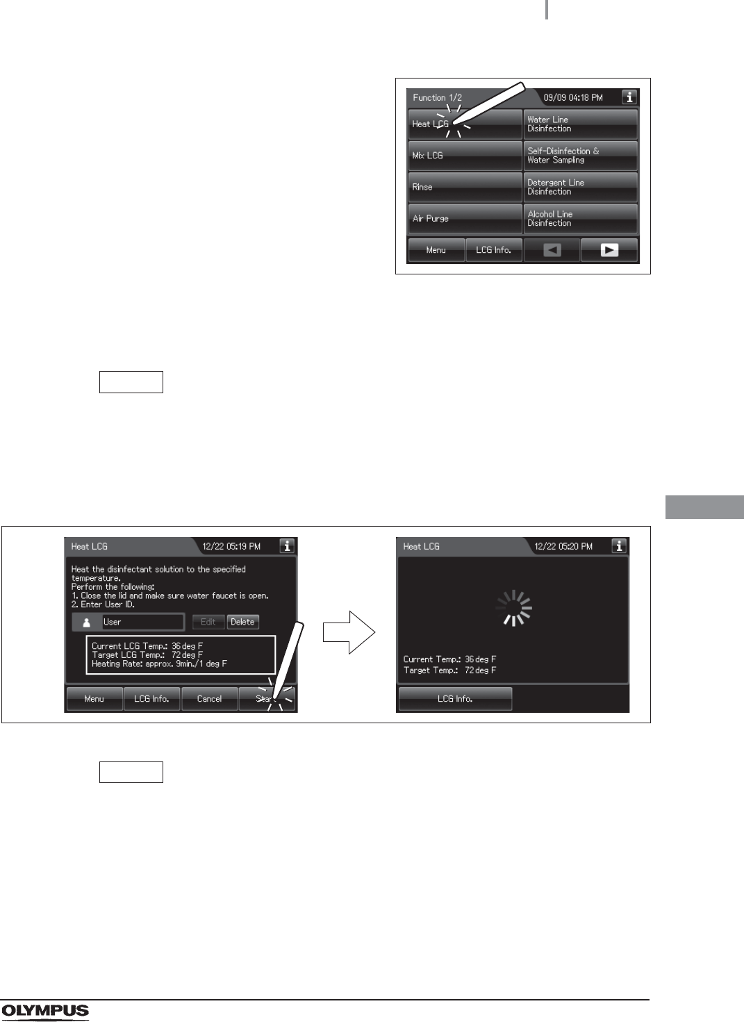
7.2 Heat LCG
243
OER-Elite OPERATION MANUAL
Ch.7
2Press the “Heat LCG” button on the 1st page of
the Function menu.
Figure 7.2
3Close the lid by pushing until it clicks and make sure water faucet is open.
4Enter the user ID. (If applicable)
NOTE
For the detailed procedure of ID entry, refer to Section 3.6, “Entering ID” (If
applicable).
5Press the “Start” button. The Heat LCG process will begin. Put the duration time on
the same page as this step.
Figure 7.3
NOTE
Heating normally takes approximately 5 minutes for every 1qC temperature rise.
6When the disinfectant solution is heated to the specified temperature, the disinfectant
solution is collected automatically and the reprocessing basin is rinsed.
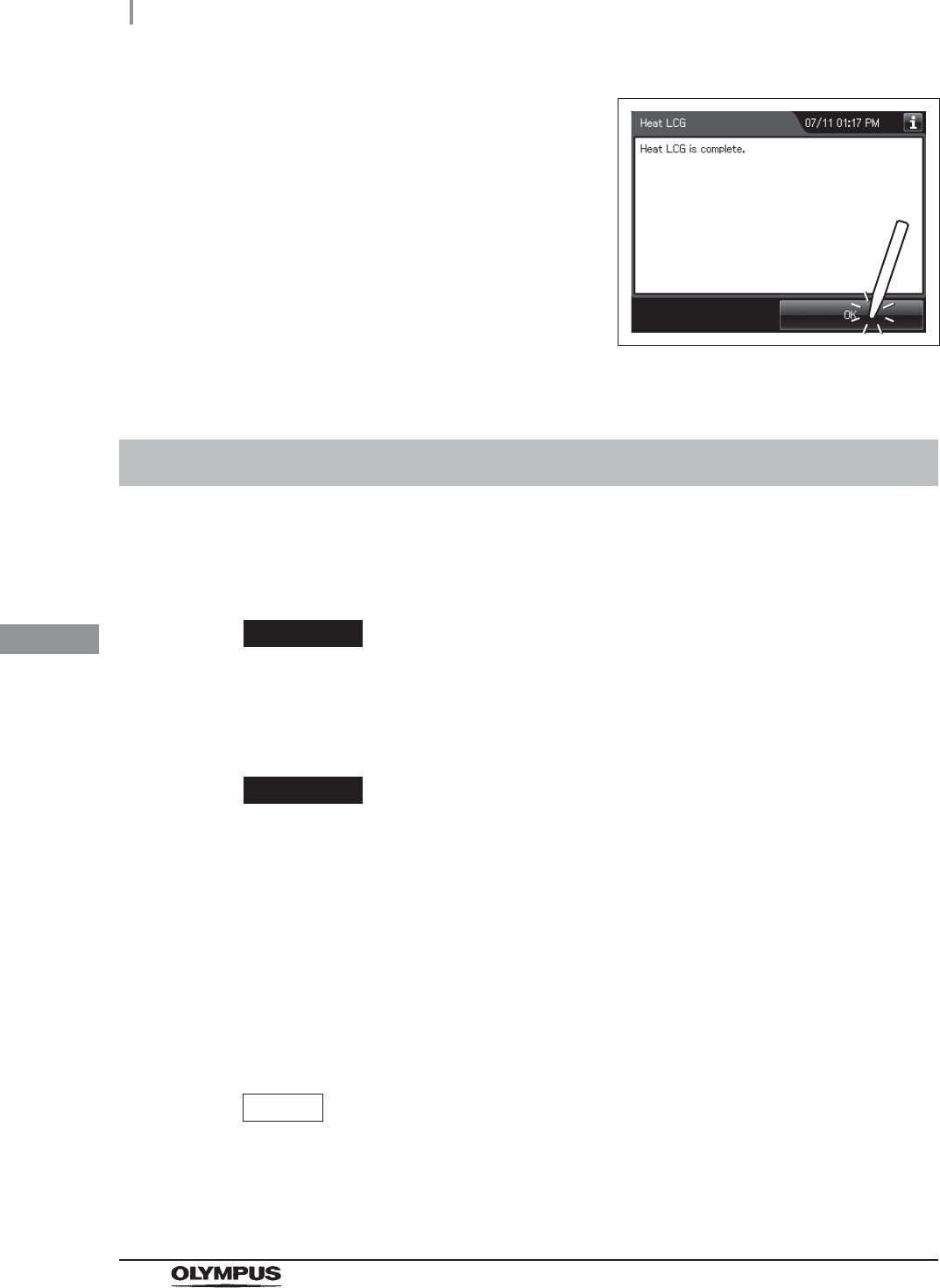
244
7.3 Heat LCG Timer
OER-Elite OPERATION MANUAL
Ch.7
This function heats the disinfectant solution to the appropriate temperature by a specified time. When
the temperature of the disinfectant solution is below 20°C (68°F), the OER-Elite will heat the
disinfectant solution to 22°C (72°F).
WARNING
Before performing the Heat LCG Timer, clean and inspect the reprocessor by
following the instructions in Chapter 10, “End-Of-Day Checks”. Otherwise, the
functions and performance of the reprocessor would be unable to be maintained.
CAUTION
• Before performing to Heat LCG Timer function, disconnect the leak test air tube
from the connector on the reprocessor and be sure to take the tube out of the
reprocessing basin. Otherwise, penetration of water or disinfectant solution inside
the leak test air tube may cause its failure. Also, the endoscope may also fail if the
water or disinfectant solution penetrating in the leak test air tube enters the
endoscope during the leak test.
• Keep the water faucet closed during standby of the Heat LCG Timer. Otherwise,
the change in the water pressure could disconnect the water supply hose and
cause water leak.
NOTE
• The user ID can be recorded in the Heat LCG record. For setting change of the
user ID input function, refer to Section 4.5, “User ID Setting”.
• Heating normally takes approximately 5 minutes for every 1qC temperature rise.
7When the Heat LCG process completes, the
reprocessor generates a buzzer beep and will
display the following screen on the touch
screen. Press the “OK” button to finish.
Figure 7.4
7.3 Heat LCG Timer
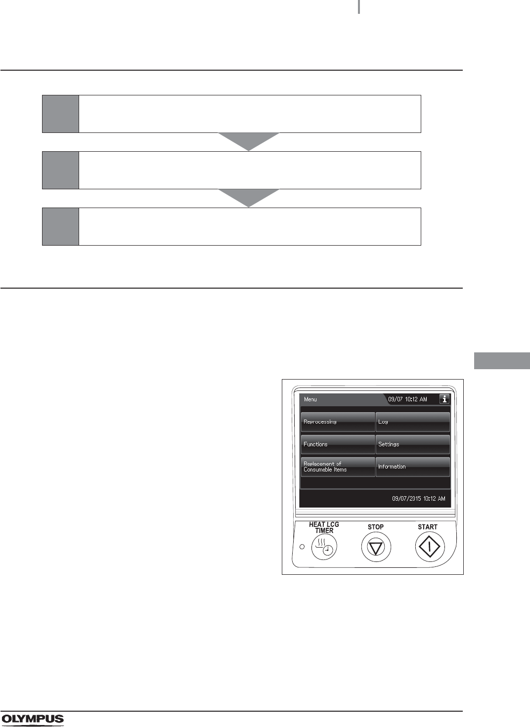
7.3 Heat LCG Timer
245
OER-Elite OPERATION MANUAL
Ch.7
Flow of Heat LCG Timer
Starting the Heat LCG Timer
1Starting the Heat LCG Timer.
on page 245
2Standing by and starting the Heat LCG Timer.
on page 253
3Finishing of the Heat LCG Timer.
on page 254
1Close the water faucet.
2Ensure that the reprocessor is ON.
3Close the lid by pushing until it clicks.
4Press the “HEAT LCG TIMER” button on the
control panel.
Figure 7.5
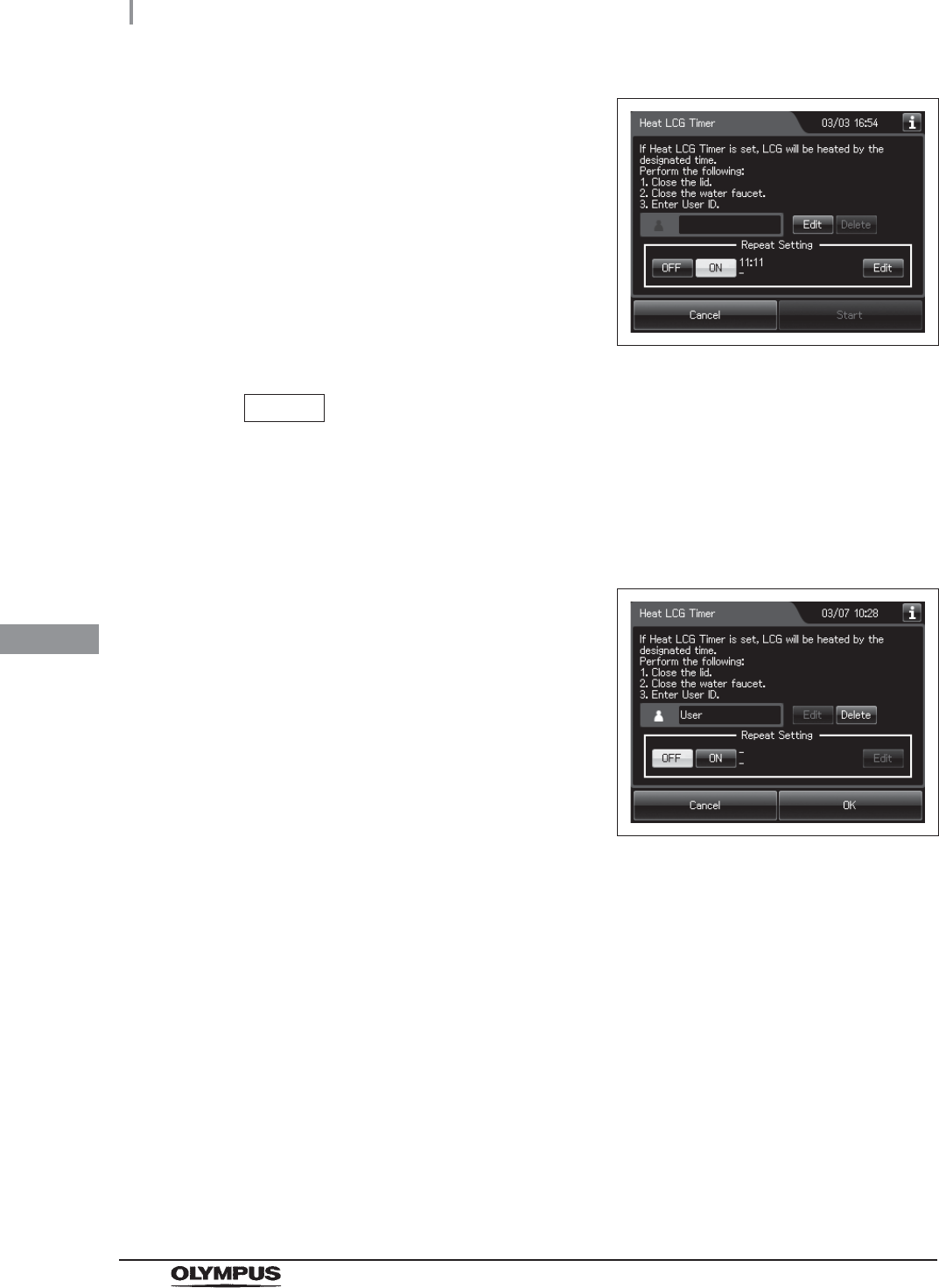
246
7.3 Heat LCG Timer
OER-Elite OPERATION MANUAL
Ch.7
5Input the user ID. For the detailed procedures,
refer to Section 3.6, “Entering ID” (If
applicable).
Figure 7.6
NOTE
• The user ID input can be omitted according to the user ID input setting. For details,
refer to Section 4.5, “User ID Setting”.
• When the user ID setting (Heat LCG Timer) is not activated, this screen is not
displayed. Skip this step.
6When set Heat LCG Timer just for one time,
press the “OFF” button in the repeat setting.
Then Press “OK” button. Refer to “(a) When
repeat setting is selected “OFF”” on page 248.
When you want to set Heat LCG Timer
repeatedly, press the “ON” button in the repeat
setting. Refer to “(b) When repeat setting is
selected “ON”” on page 250.
Figure 7.7
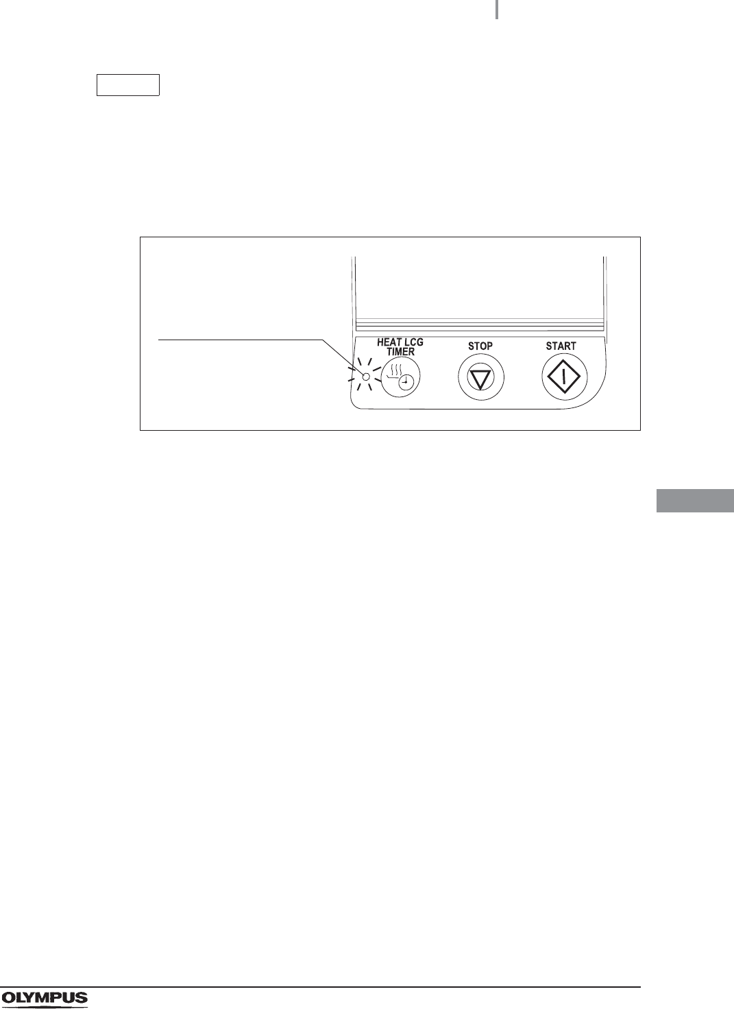
7.3 Heat LCG Timer
247
OER-Elite OPERATION MANUAL
Ch.7
NOTE
• Do not turn the main power off. Doing so disables the Heat LCG.
• To display the touch screen again, press the touch screen or any button on the
control panel.
• To stop the Heat LCG Timer setting, press “STOP” button on the reprocessor.
• The Heat LCG Timer Indicator light even when the touch screen displays nothing.
Figure 7.8
Heat LCG timer indicator
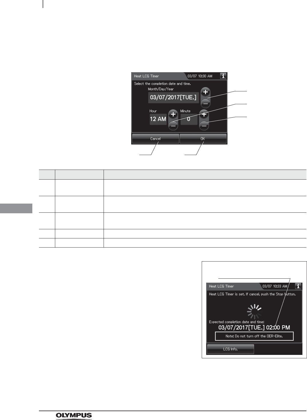
248
7.3 Heat LCG Timer
OER-Elite OPERATION MANUAL
Ch.7
(a) When repeat setting is selected “OFF”
1Change the completion date/time and press the “OK” button.
No. Item/Button Description
1 Change completion
date
Sets the date of Heat LCG Timer completion.
Pressing the + button increments the setting and pressing the – button decrements it.
2 Change completion
time (Hour)
Sets hour of Heat LCG Timer completion.
Pressing the + button increments the setting and pressing the – button decrements it.
3 Change completion
time (Min.)
Sets minute of Heat LCG Timer completion.
Pressing the + button increments the setting and pressing the – button decrements it.
4 Cancel Cancels the setting change.
5 OK Goes to the next screen page after saving the edited information.
2The touch screen display changes as shown
Figure 7.9 and appear to turn off after
5 minutes of inactivity, the touch screen
appears to turn off and the Heat LCG Timer
enters the standby mode.
Figure 7.9
1
4
2
3
5
Heat LCG Timer completion
date/time setting
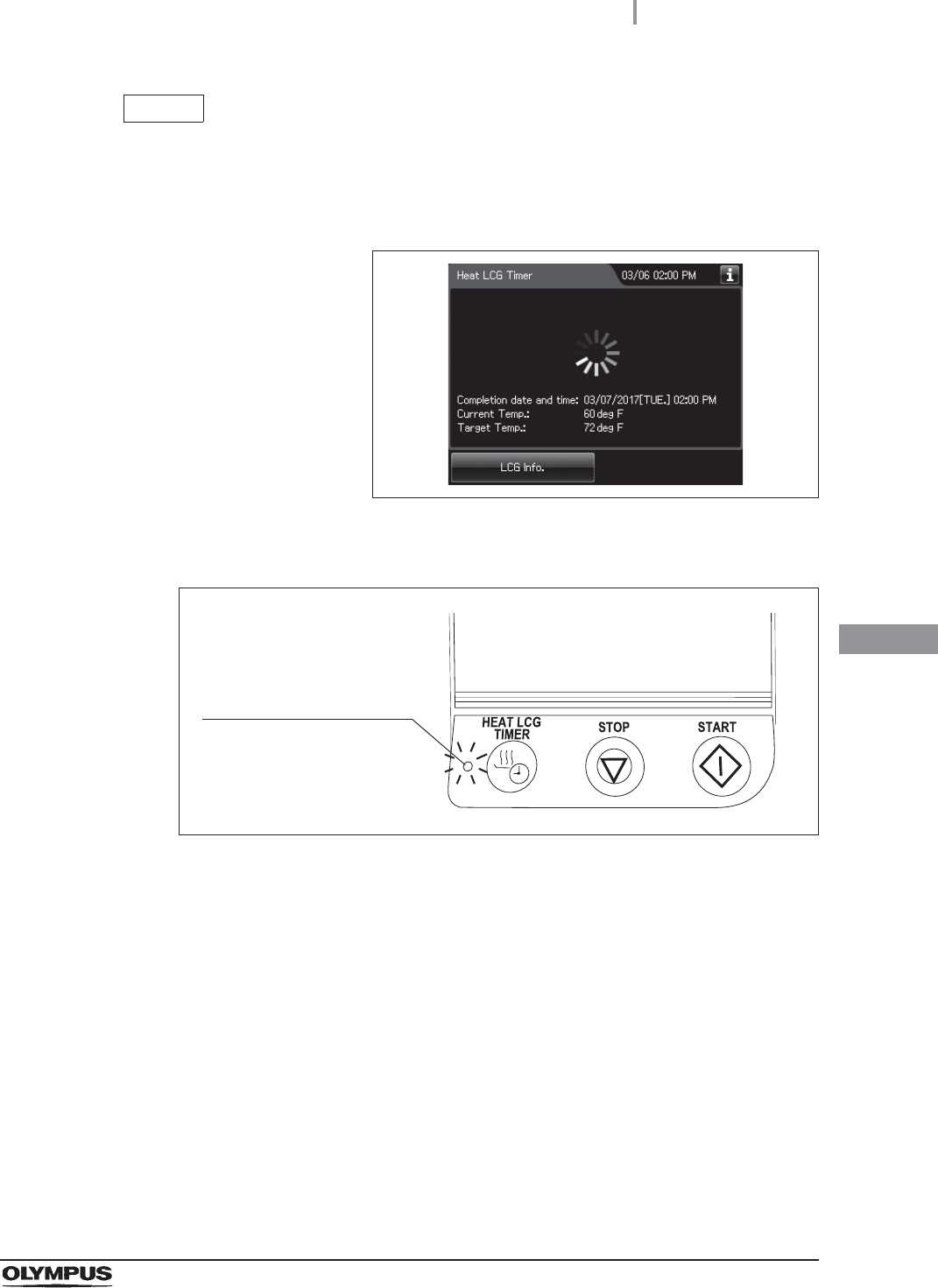
7.3 Heat LCG Timer
249
OER-Elite OPERATION MANUAL
Ch.7
NOTE
• If no operation is made more than 5 minutes, the touch screen appears to turn off.
To display the touch screen again, press the touch screen or the button on the
control panel. For detail of executing, the touch screen displays a screen as shown
Figure 7.10.
Figure 7.10
• The Heat LCG Timer Indicator light even when the touch screen displays nothing.
Figure 7.11
Heat LCG timer indicator
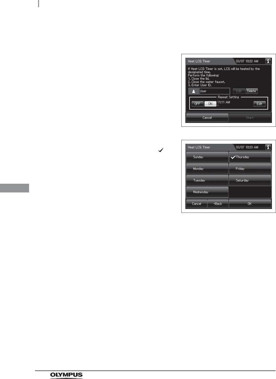
250
7.3 Heat LCG Timer
OER-Elite OPERATION MANUAL
Ch.7
(b) When repeat setting is selected “ON”
Under the repeat setting, the Heat LCG Timer is repeated weekly based on the specified day(s).
1Press the “Edit” button in the repeat setting.
Figure 7.12
2Select the day(s) of you want to run the Heat
LCG Timer and press the “OK” button. “ ” is
marked on the selected day(s).
Figure 7.13
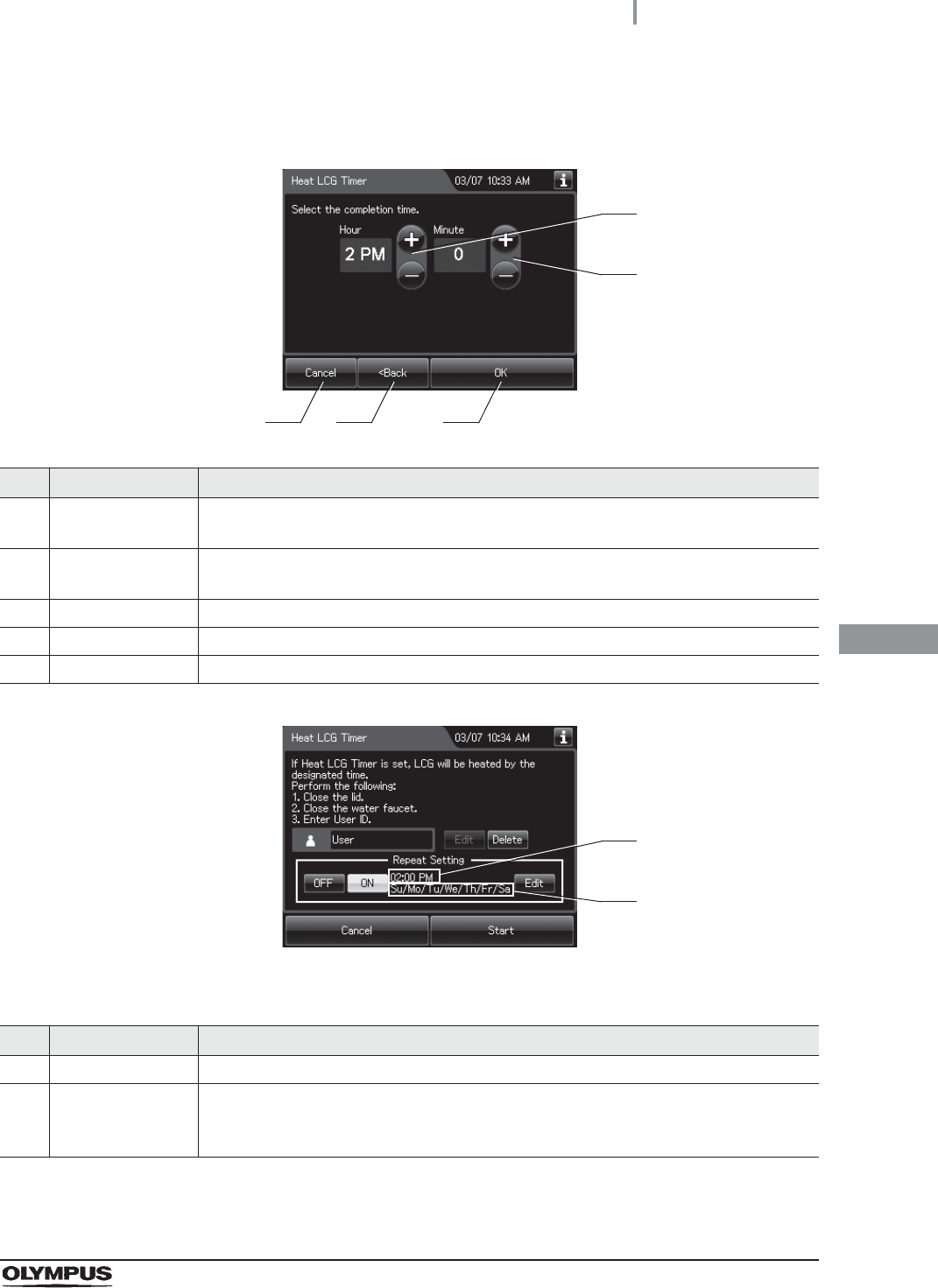
7.3 Heat LCG Timer
251
OER-Elite OPERATION MANUAL
Ch.7
3Set the Heat LCG Timer completion time and press the “OK” button.
No. Item/Button Description
1 Change completion
time (Hour)
Sets hour of Heat LCG Timer completion.
Pressing the + button increments the setting and pressing the – button decrements it.
2 Change completion
time (Min.)
Sets minute of Heat LCG Timer completion.
Pressing the + button increments the setting and pressing the – button decrements it.
3 Cancel Cancels the setting change.
4 Back Returns to the days of the week selection menu.
5 OK Returns to the setting menu of Heat LCG Timer after saving the edited information.
No. Item Description
1 Completion Time Sets the time of Heat LCG Timer completion.
2 Completion day of
week
Sets the day of week of Heat LCG Timer completion.
Su: Sunday, Mo: Monday, Tu: Tuesday, We: Wednesday, Th: Thursday, Fr: Friday,
Sa: Saturday
1
3 5
2
4
1
2
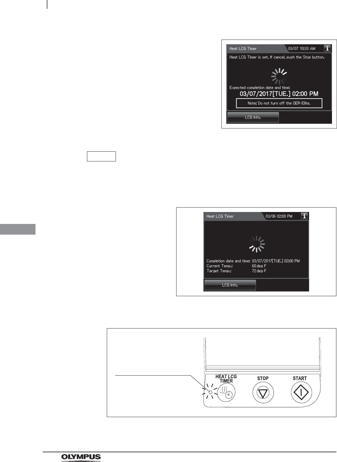
252
7.3 Heat LCG Timer
OER-Elite OPERATION MANUAL
Ch.7
NOTE
• If no operation is made more than 5 minutes, the touch screen appears to turn off.
To display the touch screen again, press the touch screen or the button on the
control panel. For detail of executing, the touch screen displays a screen as shown
Figure 7.15.
Figure 7.15
• The Heat LCG Timer Indicator light even when the touch screen displays nothing.
Figure 7.16
4Press the “Start” button on the touch screen.
Then, the Heat LCG Timer is started. The touch
screen display changes as shown Figure 7.14
and appear to turn off after 5 minutes of
inactivity, the touch screen appears to turn off
and the Heat LCG Timer enters the standby
mode.
Figure 7.14
Heat LCG timer indicator
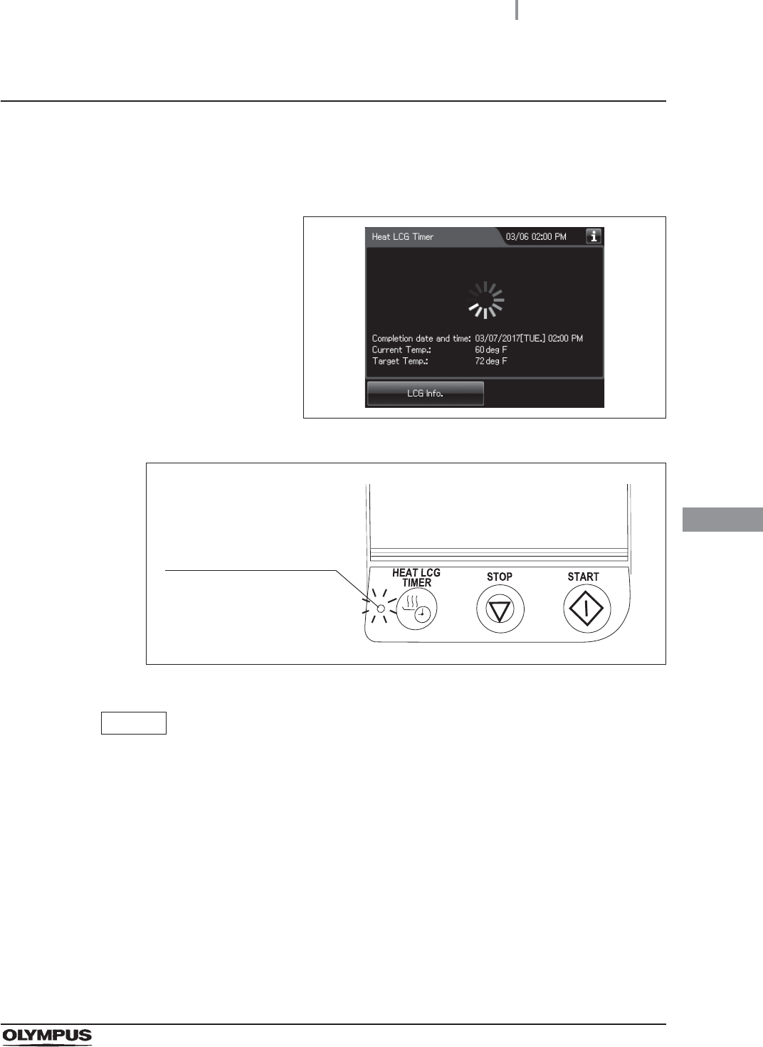
7.3 Heat LCG Timer
253
OER-Elite OPERATION MANUAL
Ch.7
Standing by and starting the Heat LCG Timer
During standby and the heating process, the Heat LCG indicator lights and the touch screen appears
to turn off.
If the touch screen or any button on the control panel is pressed during heating process, the touch
screen displays the following screen.
Figure 7.17
Figure 7.18
NOTE
Heating normally takes approximately 5 minutes for every 1qC temperature rise.
Heat LCG timer indicator
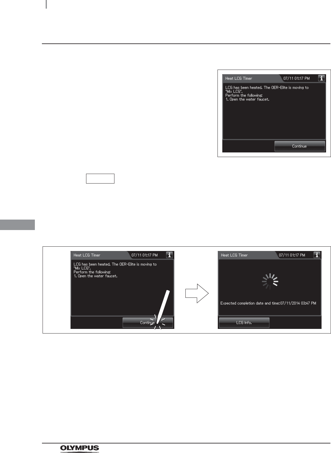
254
7.3 Heat LCG Timer
OER-Elite OPERATION MANUAL
Ch.7
Finishing the Heat LCG Timer
1When heating process completes, the touch
screen display changes as shown on the
Figure 7.19.
Figure 7.19
NOTE
When heating process completes, the reprocessor starts the mixing LCG process.
Because the MRC check result may become erroneous.
2Open the water faucet.
3Press the “Continue” button to start mixing the disinfectant solution.
Figure 7.20
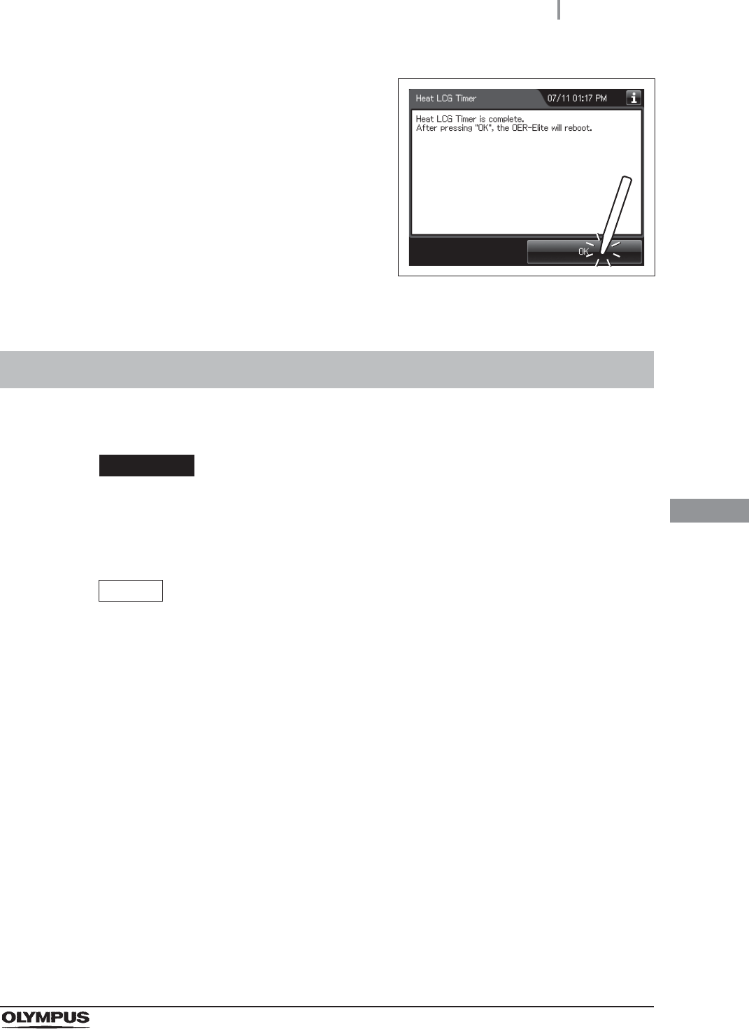
7.4 Mix LCG
255
OER-Elite OPERATION MANUAL
Ch.7
This function mixes the disinfectant solution to enable an accurate concentration check.
WARNING
If Mix LCG is performed while the endoscopes are placed in the reprocessing
basin, the endoscopes must be reprocessed after the Mix LCG. Otherwise, the
endoscopes cannot be reprocessed sufficiently.
NOTE
• To ensure accurate MRC check, mix LCG is generally required at the first use of
the day. Also, mix LCG is required when the interval of reprocessing operation is
beyond 4 hours. If the mix LCG is required, the message is automatically displayed
on the touch screen.
• If the MRC check is entered a long time (maximum 5 days) after the previous use of
the disinfectant, the touch screen may display the guidance for the request of the
Mix LCG.
4When the mixing the disinfectant solution
completes, the touch screen displays the
following screen. Press the “OK” button. Then,
the OER-Elite will reboot automatically.
Figure 7.21
7.4 Mix LCG
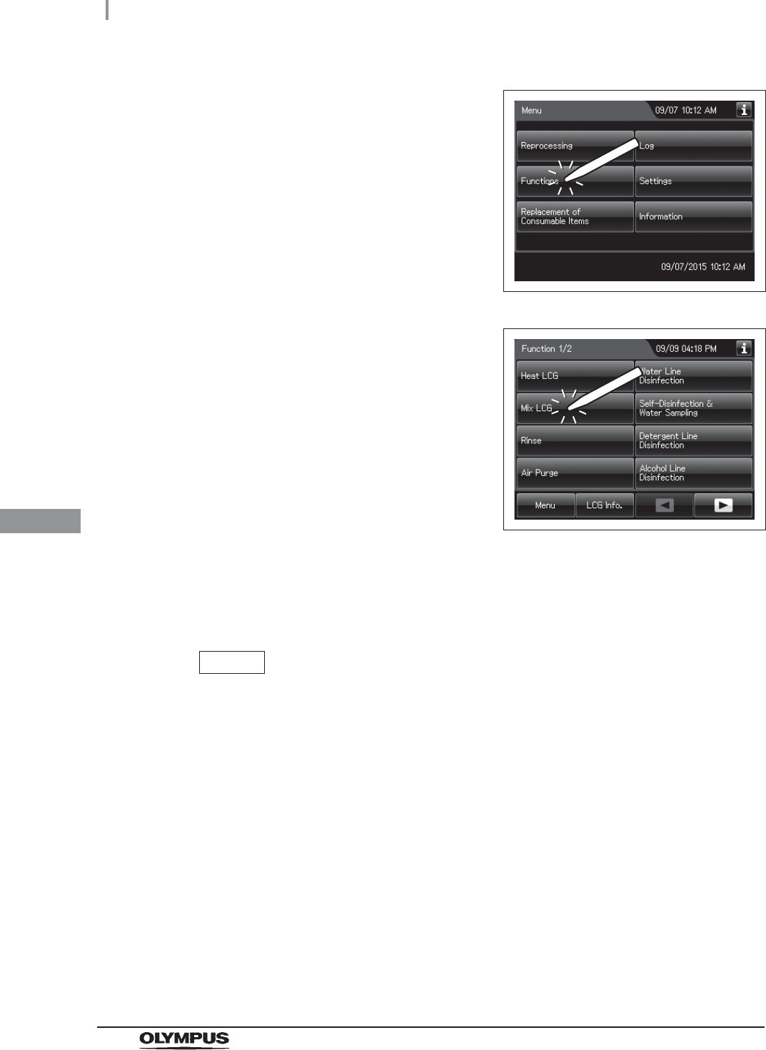
256
7.4 Mix LCG
OER-Elite OPERATION MANUAL
Ch.7
1Press “Functions” on the Menu screen.
Figure 7.22
2Press the “Mix LCG” button on the Function
menu.
Figure 7.23
3Follow the guide displayed on the touch screen. Close the lid by pushing until it clicks
and make sure the water faucet is open.
4Enter the user ID. (If applicable)
NOTE
The user ID input can be omitted according to the user ID input setting. For details,
refer to Section 4.5, “User ID Setting”.
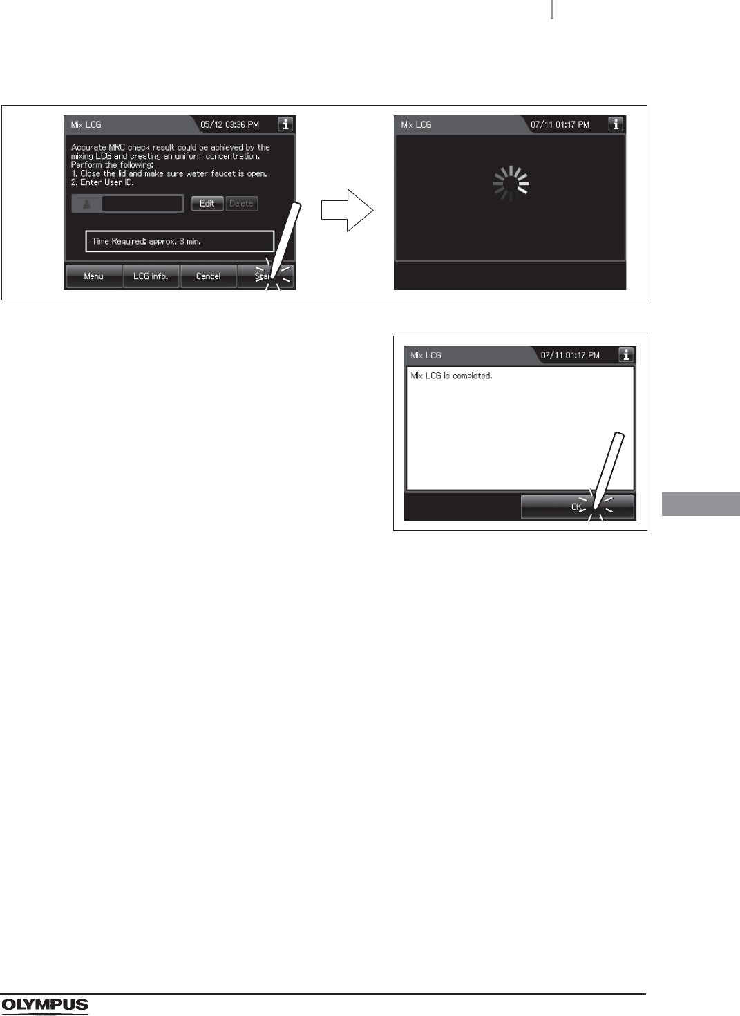
7.4 Mix LCG
257
OER-Elite OPERATION MANUAL
Ch.7
5Press the “Start” button. Mix LCG process starts.
Figure 7.24
6When the Mix LCG process completes, the
reprocessor generates a buzzer beep and
displays the following screen on the touch
screen. Press the “OK” button to finish.
Figure 7.25
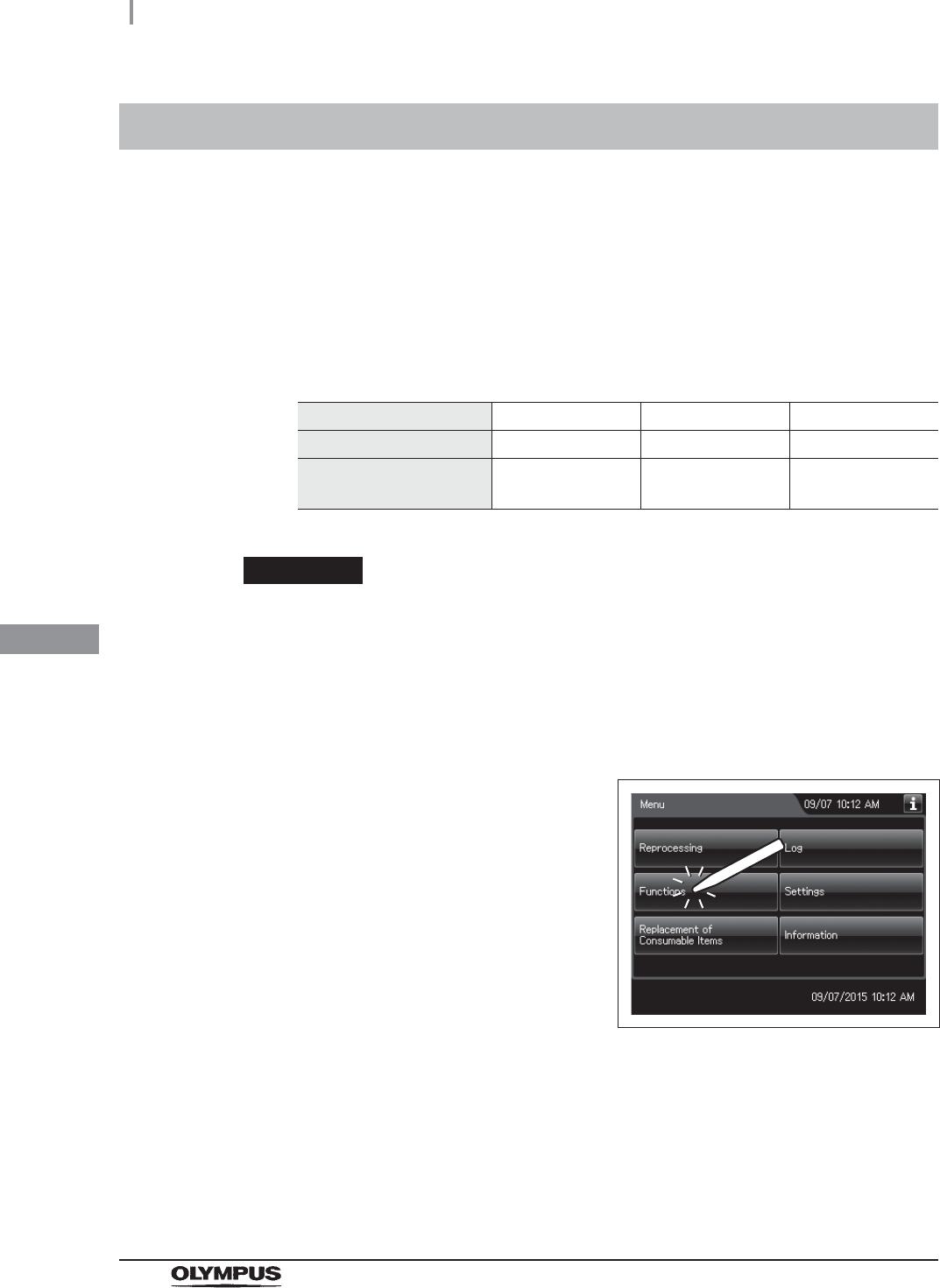
258
7.5 Rinse
OER-Elite OPERATION MANUAL
Ch.7
If cleaning fluid or disinfectant solution remains in the reprocessing basin or inside the lumens of the
endoscope after an irregularity occurs or if the process is stopped before it completes, please the rinse
process after the completion of the air purge process.
After disinfection, a water rinse is performed three times. Rinse conditions such as number of rinses
performed and rinse time cannot be changed. Worst case time and water volume of each rinse cycle
are shown below. Time and water volume can vary depending on endoscope models, number of
endoscopes loaded and water supply conditions.
Table 7.1
CAUTION
• Be sure to perform the air purge first if cleaning fluid or disinfectant solution is still in
the reprocessing basin or endoscopes. Otherwise, rinse may be insufficient.
• Before starting the rinse, always confirm that there is no foreign material on the
ventilation openings on the gas filter cases. Blocking the ventilation not only
hinders deodorization but may also cause the reprocessor to malfunction.
7.5 Rinse
Rinse cycle 1st cycle 2nd cycle 3rd cycle
Time 100 s 110 s 130 s
Rinse water volume 14.7 L
3.9 gallons
17.9 L
4.7 gallons
17.9 L
4.7 gallons
1Press the “Functions” button on the Menu
screen.
Figure 7.26
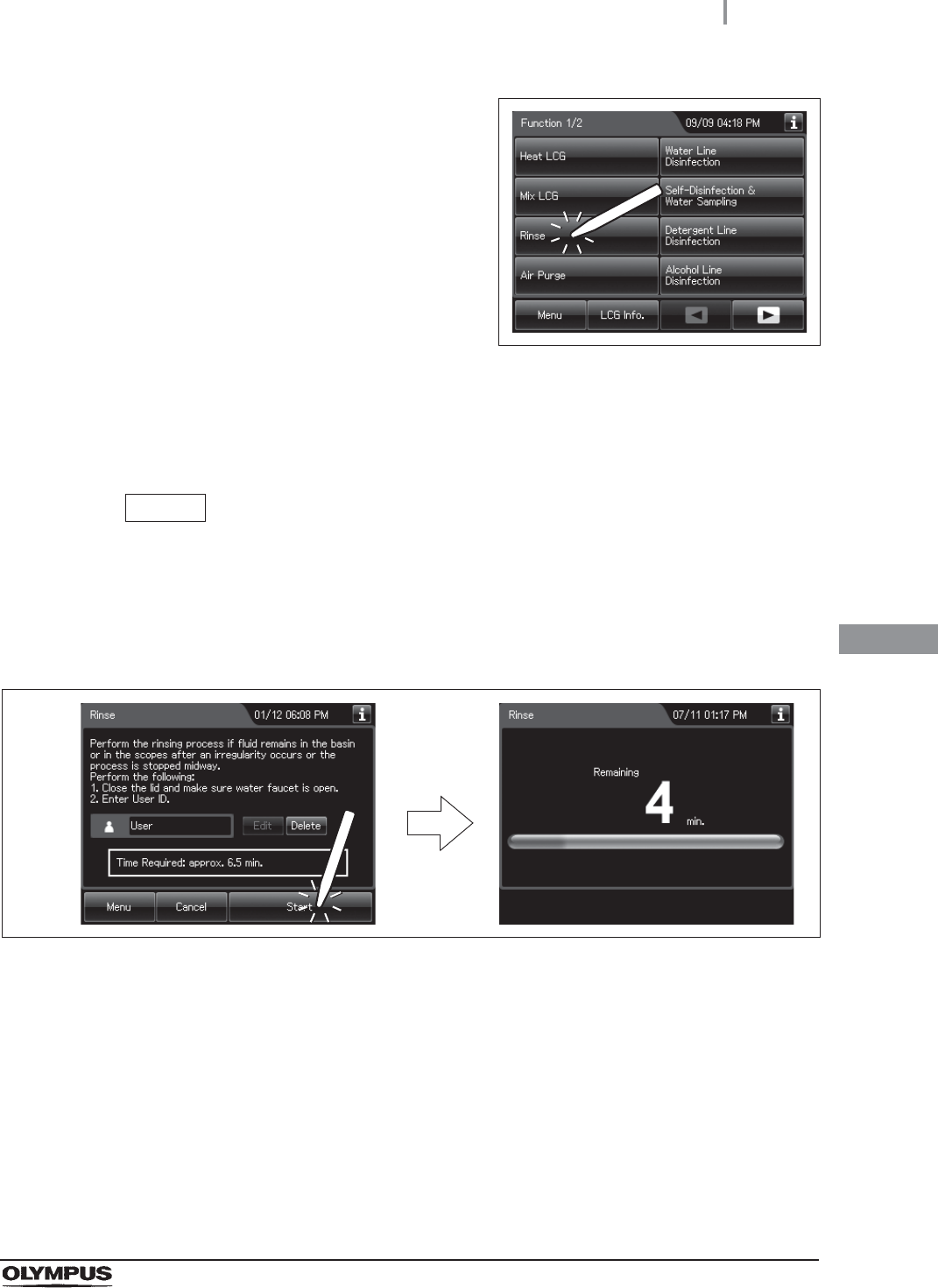
7.5 Rinse
259
OER-Elite OPERATION MANUAL
Ch.7
2Press the “Rinse” button on the Function menu.
Figure 7.27
3Follow the guide displayed on the touch screen. Close the lid by pushing until it clicks
and make sure water faucet is open.
4Enter the user ID. (If applicable)
NOTE
The user ID input can be omitted according to the user ID input setting. For details,
refer to Section 4.5, “User ID Setting”.
5Press the “Start” button. Rinse starts and the touch screen displays the remaining
time, which will count down every minute.
Figure 7.28
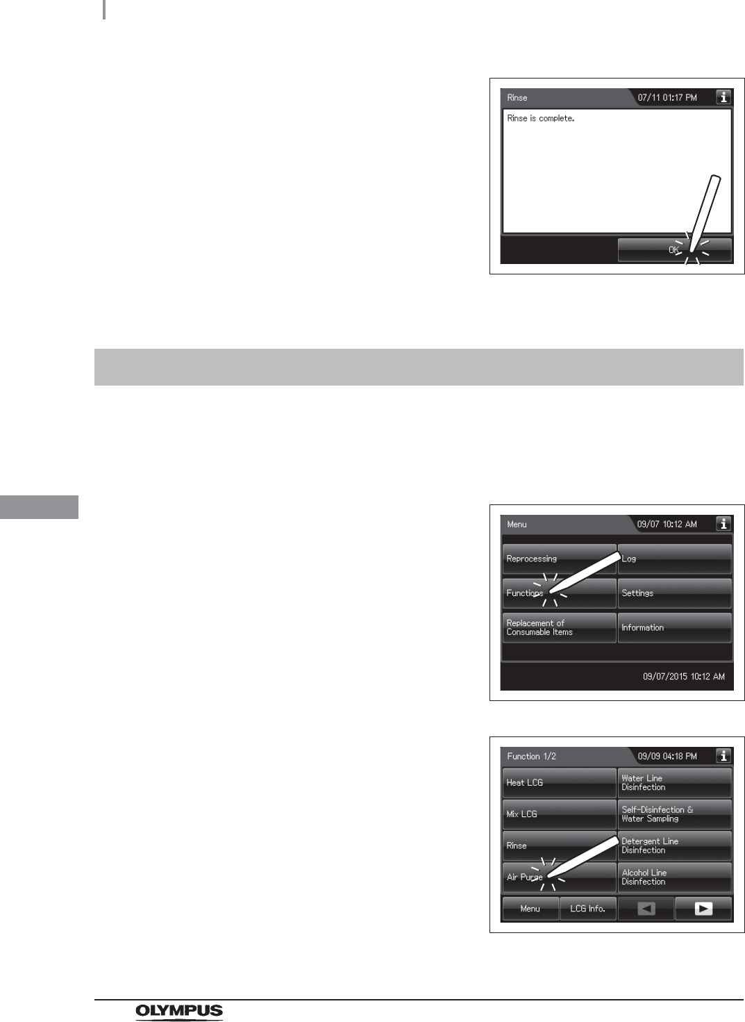
260
7.6 Air purge
OER-Elite OPERATION MANUAL
Ch.7
Air purge is performed to drain the remaining cleaning fluid and disinfectant solution from the basin
after an irregularity occurs, or if the process is stopped before it completes. Air purge also eliminates
residual fluid from the endoscope channels.
6When the rinse process completes, the
reprocessor generates a buzzer beep and
displays the following screen on the touch
screen. Press the “OK” button to finish.
Figure 7.29
7.6 Air purge
1Press the “Functions” button on the Menu
screen.
Figure 7.30
2Press the “Air Purge” button on the Function
menu.
Figure 7.31
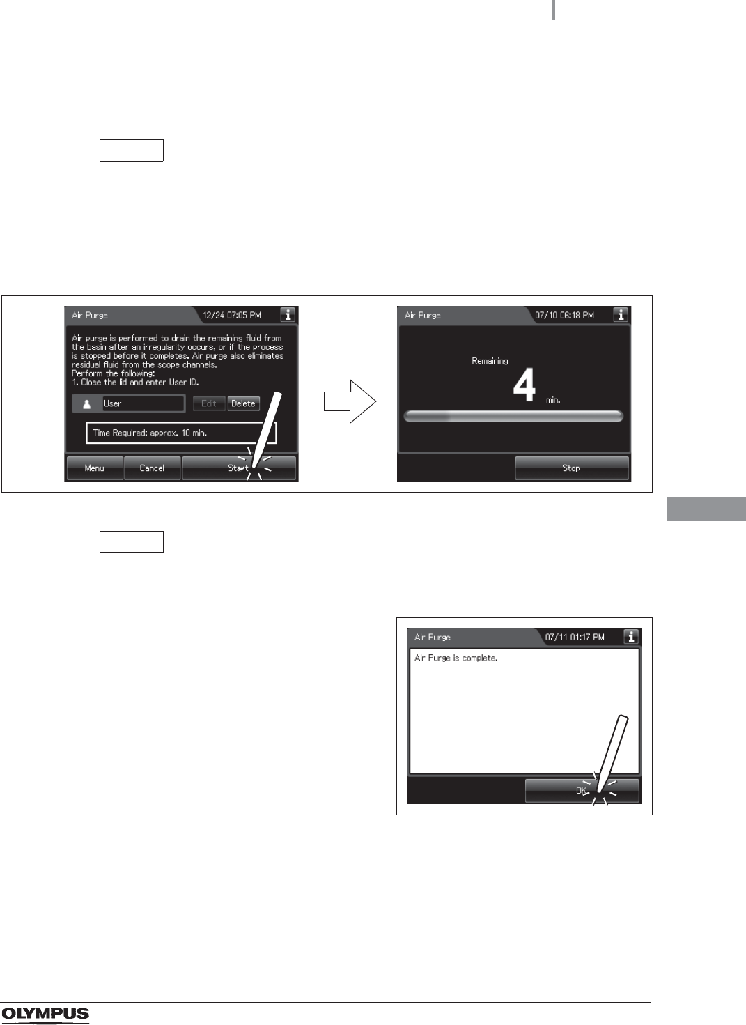
7.6 Air purge
261
OER-Elite OPERATION MANUAL
Ch.7
3Follow the guide displayed on the touch screen. Close the lid by pushing until it clicks.
4Enter the User ID (If applicable).
NOTE
The user ID input can be omitted according to the user ID input setting. For details,
refer to Section 4.5, “User ID Setting”.
5Press the “Start” button. Air purge starts and the touch screen displays the remaining
time, which will count down every minute.
Figure 7.32
NOTE
To finish the process in the middle, press the “Stop” button on the touch screen.
6When the air purge process completes, the
reprocessor generates a buzzer beep and
displays the following screen on the touch
screen. Press the “OK” button to finish.
Figure 7.33

262
7.7 Water line disinfection
OER-Elite OPERATION MANUAL
Ch.7
Disinfection of water supply piping is required in the following cases.
• Before using this reprocessor for the first time (after loading of the water filter).
• Immediately after replacement of water filter.
• Whenever bacteria in the water supply piping is identified.
• the water line disinfection at least every month.
• Before using the reprocessor if it has not been used for more than 14 days.
The disinfectant solution stored in the reprocessor is used for disinfection of the water supply piping.
WARNING
• Before disinfecting the water supply piping, check the concentration of the
disinfectant solution with the test strip, and replace the disinfectant solution if the
disinfectant concentration is below the required level. If this check is not performed,
disinfection may be insufficient.
• Disinfection of the water supply piping is required each time the water filter is
replaced (i.e., at least once a month). There may be other circumstances where
this is required, for example a flood or hurricane. Microbiological sampling of the
OER-Elite rinse water may indicate disinfection is required.
• Disconnect the connecting tubes from the connectors on the reprocessor before
disinfecting the water supply piping. Otherwise, a jet of disinfectant solution may be
output from the connecting tubes and leak from a connector such as the gas filter
case connector.
• Before handling the disinfectant solution, read the cautions carefully and use it as
instructed. It is especially important to know what to do if the disinfectant solution
comes in contact with your skin and eyes.
• When handling the disinfectant solution, wear personal protective equipment to
prevent any disinfectant from getting on your skin and eyes or being inhaled. Avoid
direct physical contact and inhalation of vapors. If any disinfectant solution gets in
your eyes, immediately rinse with a large amount of fresh water and then consult a
medical specialist. Personal protective equipment, such as eyewear, face mask,
moisture-resistant clothing, and chemical-resistant gloves that fit properly and are
long enough so that your skin and eyes is not exposed. All personal protective
equipment should be inspected before use and replaced periodically before it is
damaged.
7.7 Water line disinfection
7.7 Water line disinfection
263
OER-Elite OPERATION MANUAL
Ch.7
NOTE
• Olympus recommends performing microbiological sampling of the OER-Elite rinse
water quality right after performing the water supply piping disinfection if the
reprocessor has not been used for more than 14 days. For details on sampling
rinse water, refer to Section 7.8, “Self-disinfection and water sampling”.
• When disinfection of water supply piping is required, Olympus recommends
performing it prior to replacement of the disinfectant solution. The disinfectant
solution must still meet the MRC using the test strip. After disinfection of water
supply piping, drain the disinfectant solution according to the instructions in the
instruction manual and the facility policy. Fill the OER-Elite with fresh disinfectant
solution prior to proceeding with endoscope reprocessing.
• After disinfection of the water supply piping, the quantity and/or concentration of the
disinfectant solution might be reduced, which prevents additional reprocessing
cycles from being performed. Do not add fresh disinfectant solution to the used
disinfectant solution. Drain the disinfectant solution completely and replace with
fresh disinfectant solution after disinfection of the water supply piping. It is
recommended to perform disinfection of the water supply piping immediately before
routine replacement of the disinfectant solution.
• Disinfecting the water supply piping also disinfects the water filter and other
components in the piping.
Workflow of water line disinfection
1Checking the MRC level and entering the check result.
on page 264
2Water line disinfection.
on page 266
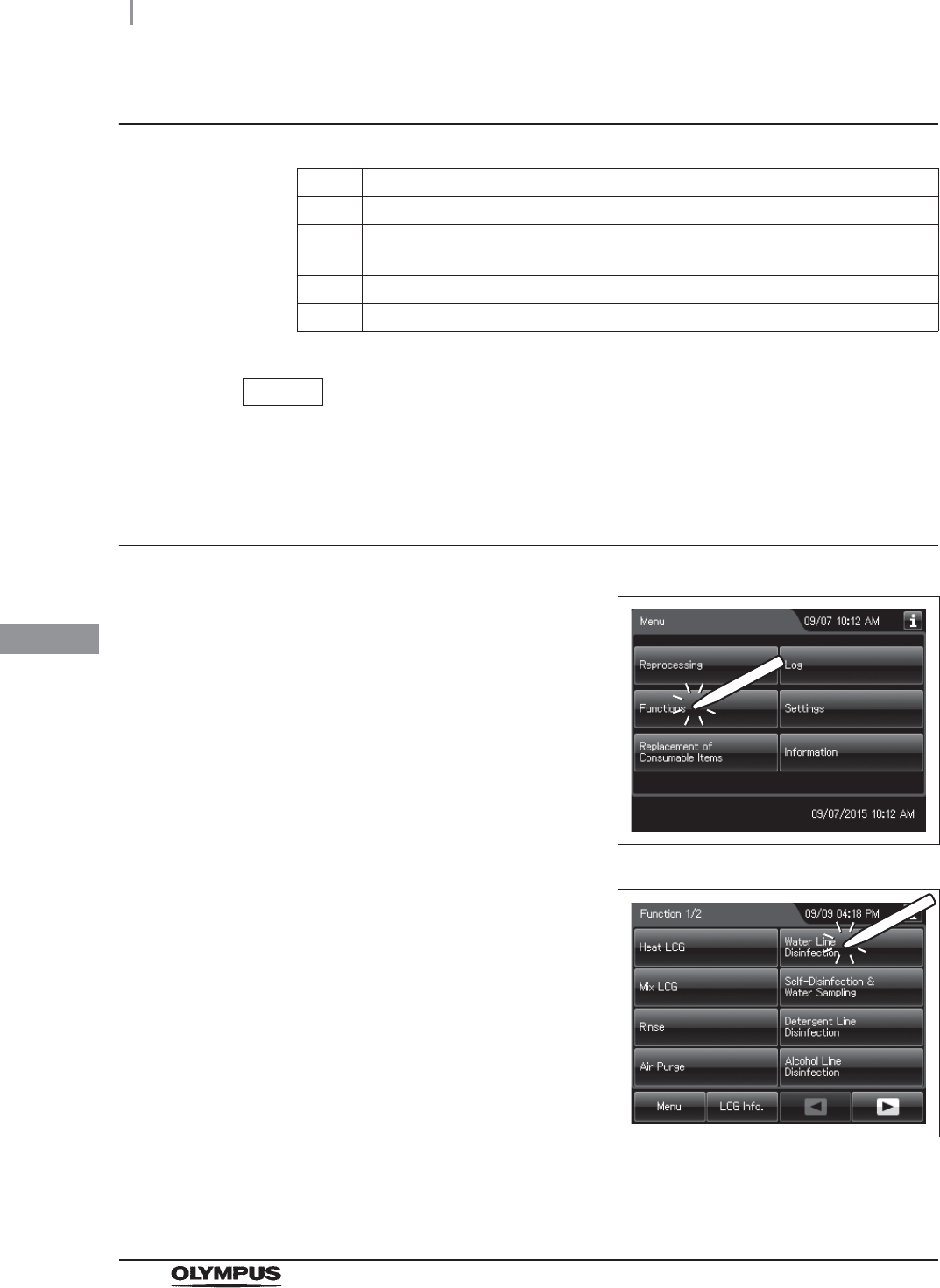
264
7.7 Water line disinfection
OER-Elite OPERATION MANUAL
Ch.7
Required items
Table 7.2
NOTE
For the test strip, refer to Section 2.8, “Consumable accessories (Optional)”.
Checking the MRC level and entering the check result
Check Required items
Chemical indicator (test strip)
Container with 2 L (67 ounces) or larger capacity (wide-mouthed container such
as a vat)
Filter tube (× 2)
Water supply piping disinfecting hose
1Press the “Functions” button on the Menu
screen.
Figure 7.34
2Press the “Water Line Disinfection”.
Figure 7.35
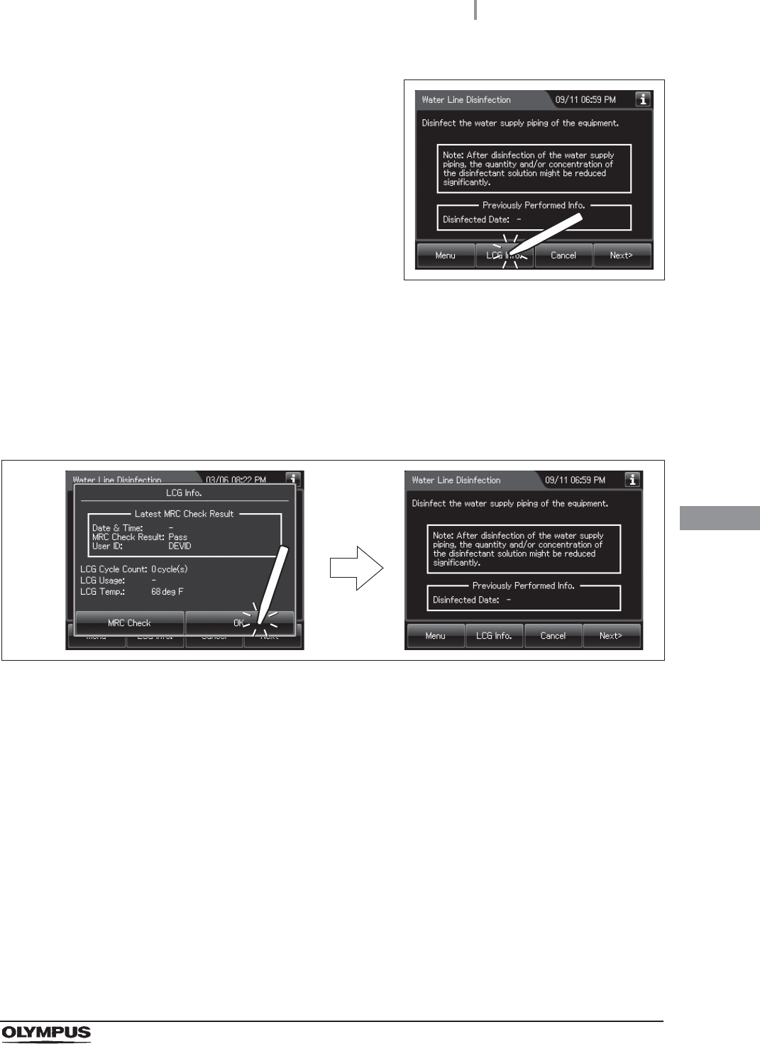
7.7 Water line disinfection
265
OER-Elite OPERATION MANUAL
Ch.7
3Press the “LCG Info.” button.
Figure 7.36
4Check the concentration of the disinfectant solution with a test strip, and enter the
result of the concentration of the disinfectant solution as described in Section 3.7,
“Checking the MRC level and entering the check result”. If the disinfectant
concentration is below required level and the disinfectant solution is beyond shelf-life
of disinfectant solution, replace the disinfectant solution.
5Press the “OK” button to close the LCG Info screen and press the “Next” button.
Figure 7.37
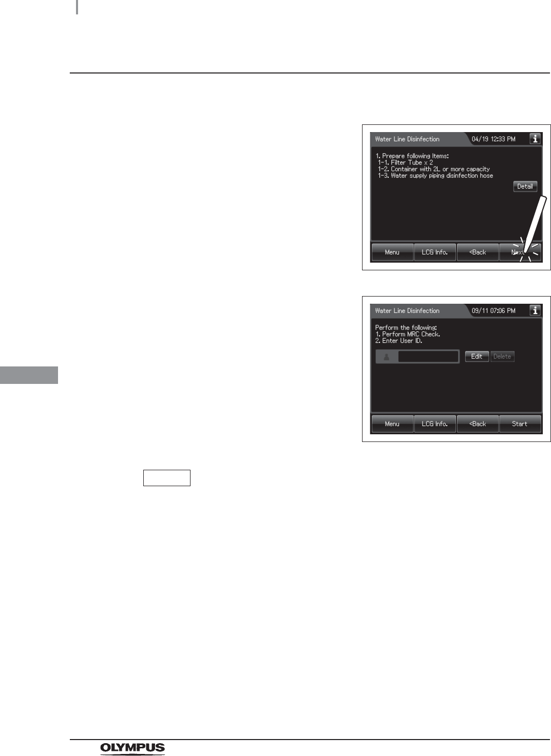
266
7.7 Water line disinfection
OER-Elite OPERATION MANUAL
Ch.7
Water line disinfection
1Make sure that the water faucet is open.
2Follow the guide displayed on the touch
screen. Press the “Next” button.
Figure 7.38
3Input the operator's user ID. For the detailed
procedures, refer to Section 3.6, “Entering ID”
(If applicable).
Figure 7.39
NOTE
• The input of the user ID can be omitted by modifying the user ID input setting. For
details, refer to Section 4.5, “User ID Setting”.
• If the “Delete” button is pressed, the entered ID can be deleted.
4Press the “Start” button.
5Push the area marked “PUSH” on the front door to open it.
6Prepare a container with a capacity of 2 L (67 ounces) or more in front of the
reprocessor.