Olympus Medical Systems RU2020 Endoscope Reprocessor User Manual GT9882 0100 fm10
Olympus Medical Systems Corp. Endoscope Reprocessor GT9882 0100 fm10
Contents
Operation Manual 3

7.7 Water line disinfection
267
OER-Elite OPERATION MANUAL
Ch.7
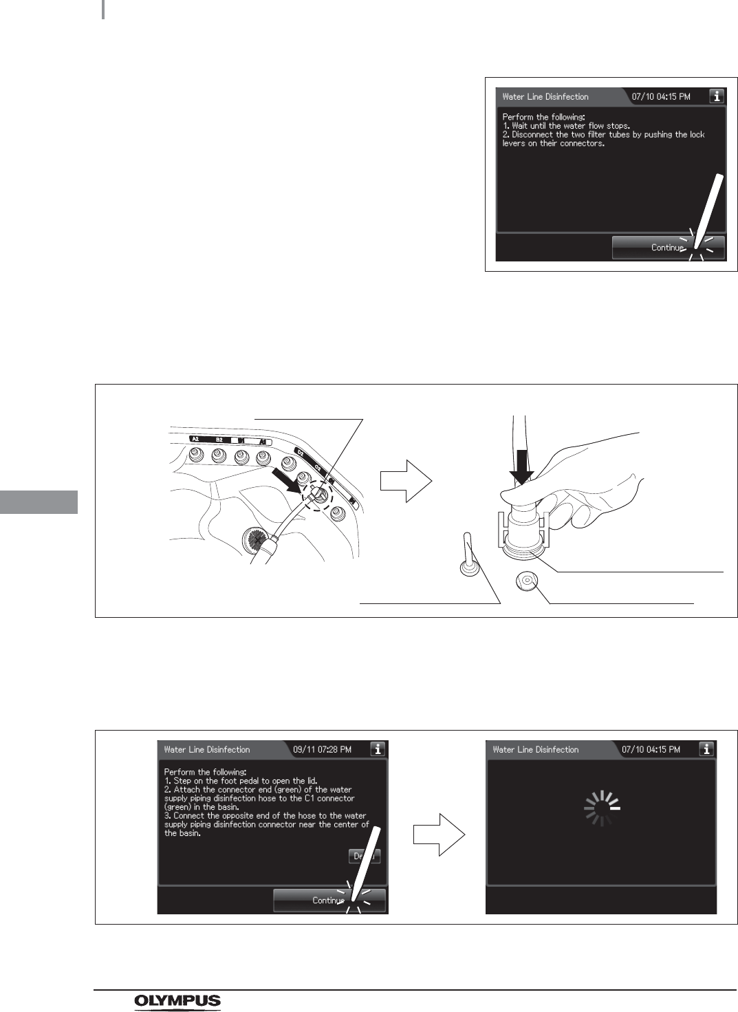
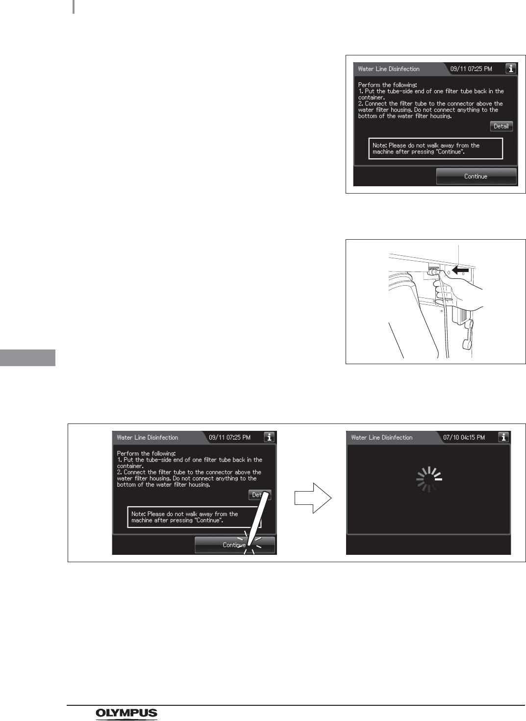
7Put the tube-side ends of the two filter tubes in the container placed and insert the
connector ends of the two filter tubes into the connector above the water filter housing
and the connector below the water filter housing until they click. Water will start to flow
from the tube connected to the connector below the water filter housing.
Figure 7.40
8Press the “Continue” button. If need more
information, press the “Detail” button.
Figure 7.41
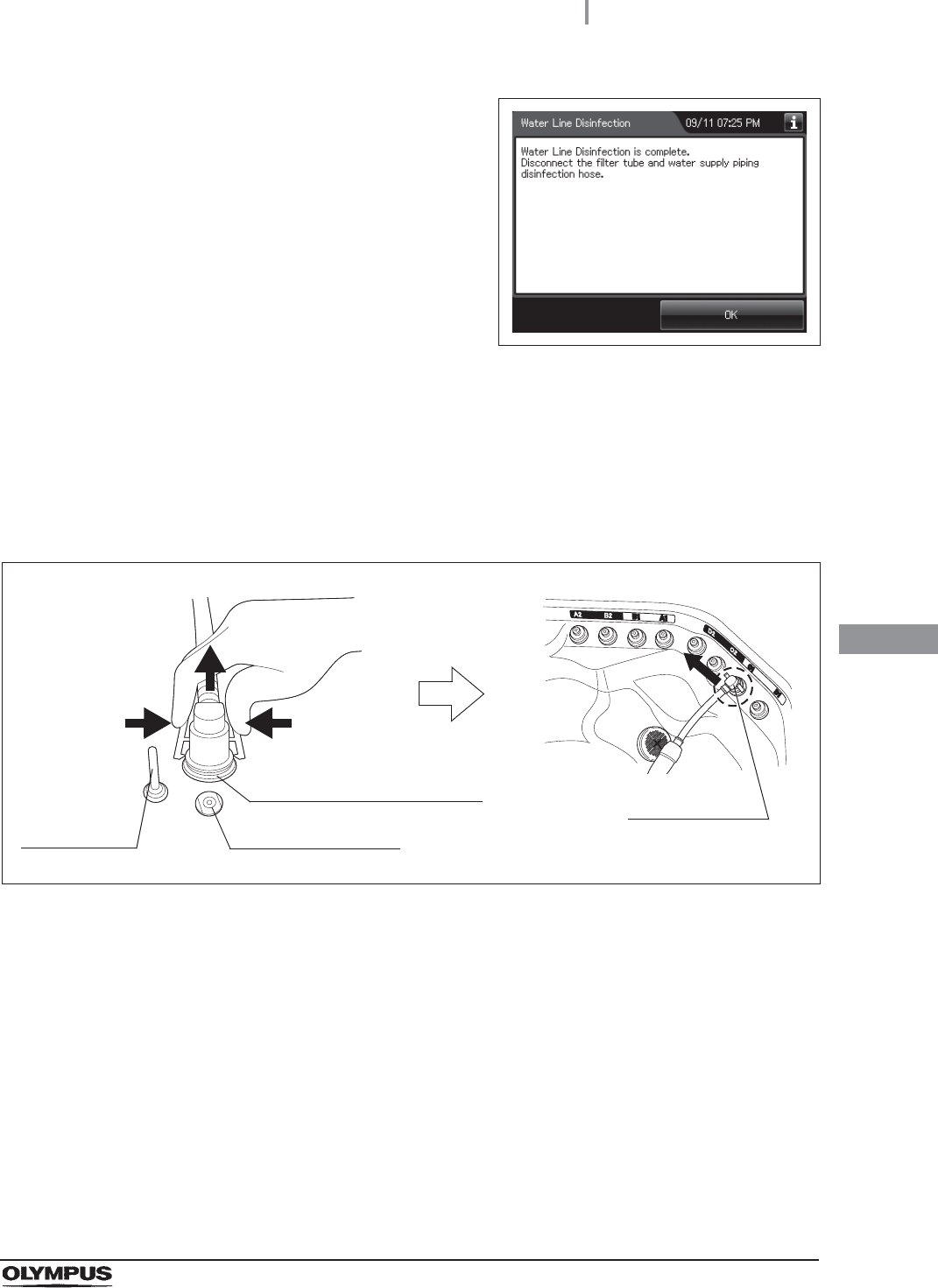
9When water flow stops, disconnect the two filter tubes by pushing the lock levers on
their connectors.
Figure 7.42
Connector below water
filter housing
Connector above water
filter housing
Lock lever
268
7.7 Water line disinfection
OER-Elite OPERATION MANUAL
Ch.7
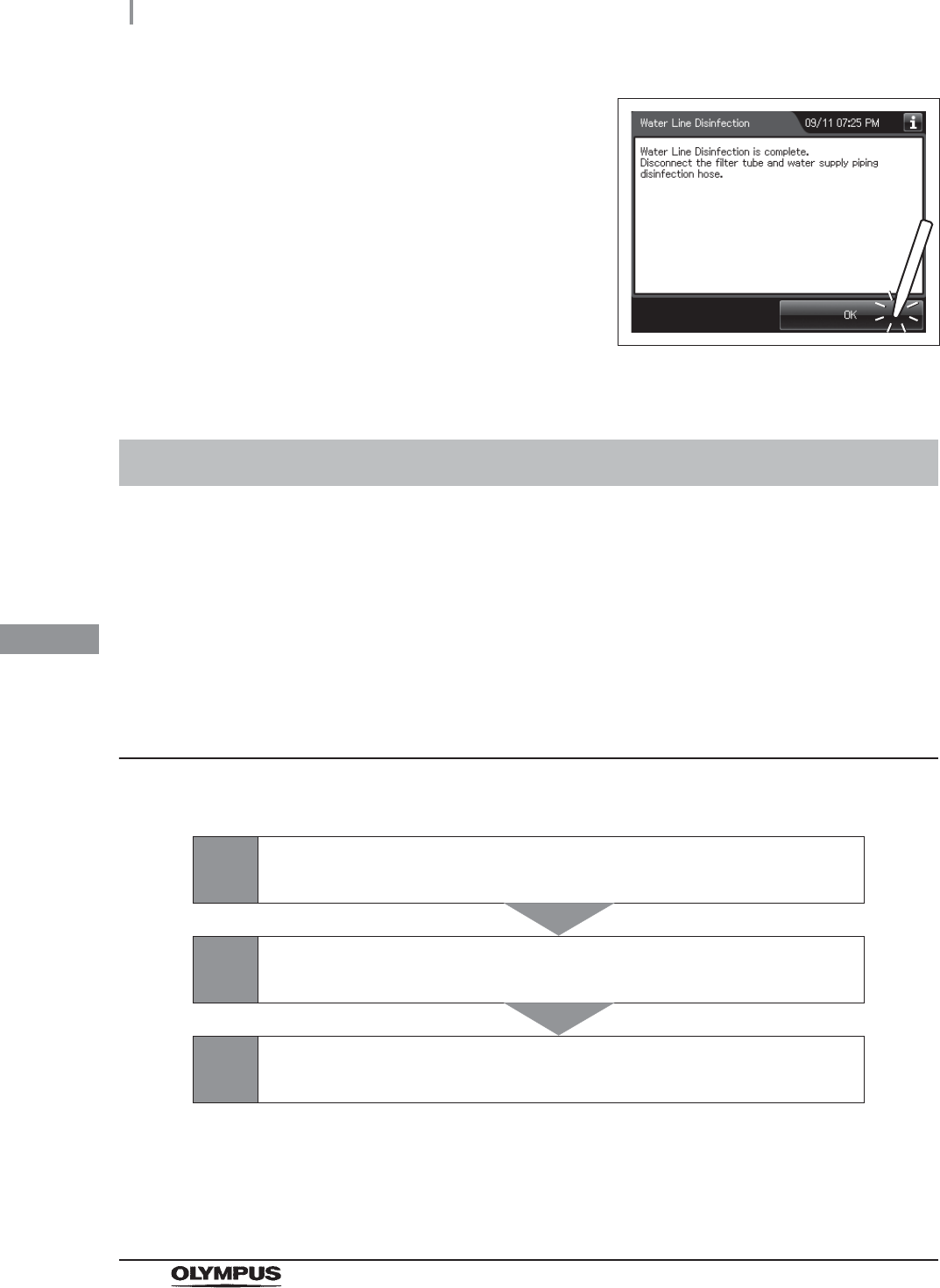
10 Press the “Continue” button.
Figure 7.43
11 Step on the foot pedal to open the lid.
12 Connect the water supply piping disinfection hose between the connector C1 in the
reprocessing basin and the water supply piping disinfection connector.
Figure 7.44
13 Close the lid by pushing until it clicks.
14 Press the “Continue” button to supply the disinfectant solution in the reprocessing
basin.
Figure 7.45
Washing case mount
Temperature sensor
Connector C1
Water supply piping
disinfection connector
7.7 Water line disinfection
269
OER-Elite OPERATION MANUAL
Ch.7
15 When the reprocessing basin is filled with
disinfectant solution, a buzzer sounds three
times and the touch screen displays the
following screen.
Figure 7.46
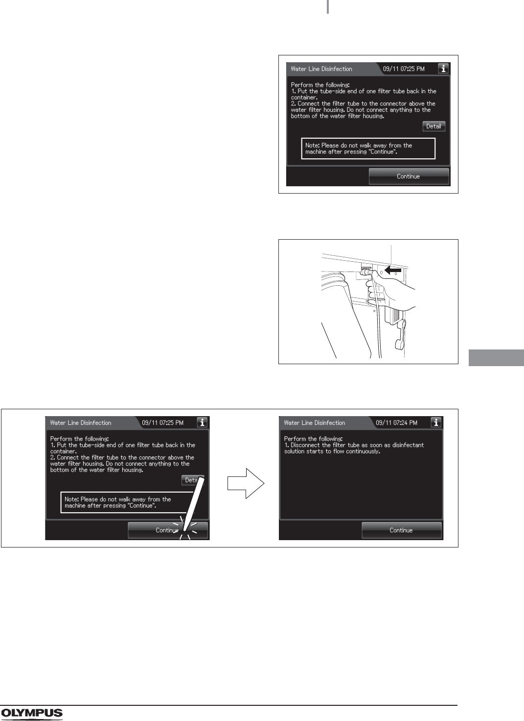
16 Put the tube-side end of the filter tube and put it in the container.
17 Insert the connector end of the filter tube into
the connector above the water filter housing
until it clicks. Do not connect anything to the
connector below the water filter housing.
Figure 7.47
18 Press the “Continue” button. Please do not walk away from the reprocessor.
Figure 7.48
270
7.7 Water line disinfection
OER-Elite OPERATION MANUAL
Ch.7
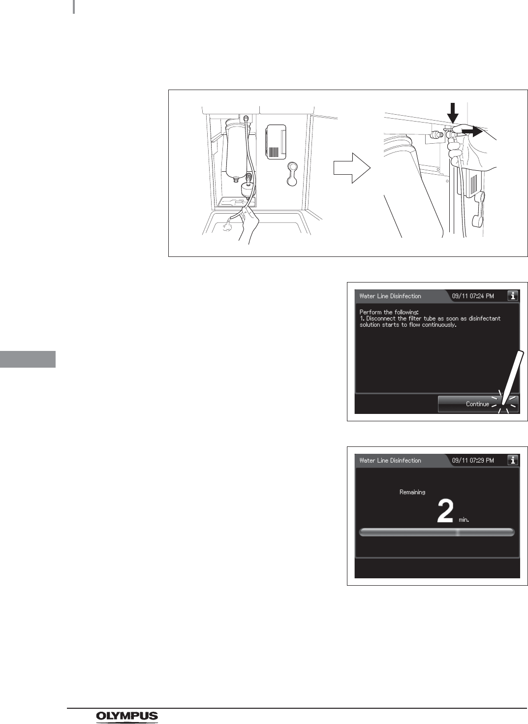
19 Disconnect the filter tube as soon as disinfectant solution starts to flow from it
continuously.
Figure 7.49
20 Press the “Continue” button.
Figure 7.50
21 When the disinfection process starts, the touch
screen displays the remaining time and the
progress bar.
Figure 7.51
7.7 Water line disinfection
271
OER-Elite OPERATION MANUAL
Ch.7
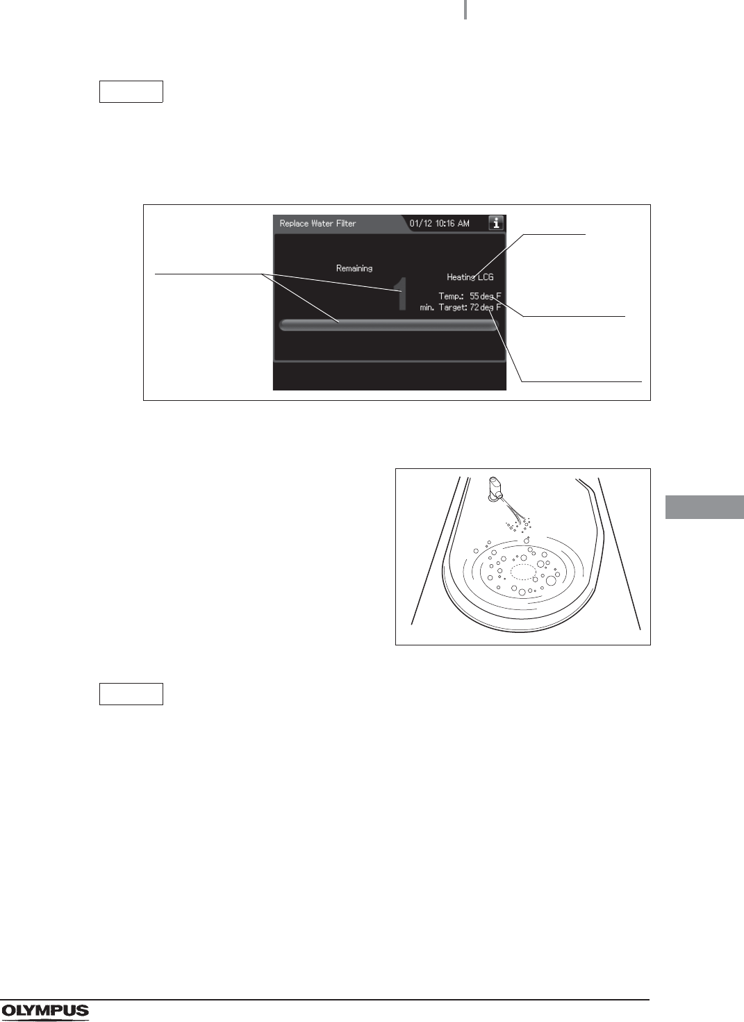
NOTE
If the temperature of the disinfectant solution is less than 20qC (68qF), it will be
heated to 20qC (68qF). During heating, the remaining time countdown and the
progress bar display stop and turn gray. After the completion of heating, the
remaining time countdown and progress bar display resume.
Figure 7.52
22 Make sure that a jet of fluid is output from the
water supply/circulation nozzle to the dome of
lid during the process.
Figure 7.53
NOTE
Fluid jet from the water supply/circulation nozzle of this process is gentler than
other processes such as the endoscope reprocessing process. As a result, fluid
spreads on less than half of dome part of the lid whereas the fluid jet of other
process spreads on entire dome part of the lid. This difference is due to use of a
different pump and therefore the gentle fluid flow of this process is adequate.
Progress stops
and turns gray.
It blinks
Current
temperature of
the disinfectant
solution
Target temperature
of the disinfectant
solution
272
7.7 Water line disinfection
OER-Elite OPERATION MANUAL
Ch.7
23 When the remaining time displayed on the
touch screen reaches 0 minutes, the buzzer
sounds and the touch screen displays the
following screen.
Figure 7.54
24 Put the tube-side end of the filter tube back in the container.
25 Connect the connector end of the filter tube into
the connector above the water filter housing.
Do not connect a filter tube to the connector
below the water filter housing.
Figure 7.55
26 Press the “Continue” button. The touch screen displays a screen as shown in the
following figure and water will flow from the filter tube.
Figure 7.56
7.7 Water line disinfection
273
OER-Elite OPERATION MANUAL
Ch.7
27 After several seconds, the buzzer sounds
indicating the end of the process and the touch
screen displays the following screen.
Figure 7.57
28 Disconnect the filter tube by pushing its lock lever.
29 Close the front door.
30 Step on the foot pedal to open the lid.
31 Disconnect the water supply piping disinfection hose and close the lid by pushing until
it clicks.
Figure 7.58
32 Rinse the filter tube and water supply piping disinfection hose thoroughly in running
water, dry them thoroughly, and store in a clean place.
Water supply piping
disinfection hose connector
Washing case mount
Temperature
sensor
Connector C1
274
7.8 Self-disinfection and water sampling
OER-Elite OPERATION MANUAL
Ch.7
Self-Disinfection is required in the following cases.
Before using this reprocessor for the first time.
Before using this reprocessor when it has not been used for more than 14 days.
In addition, it is recommended that sampling for microbiological surveillance is performed at the end of
self-disinfection process.
Workflow of self-disinfection
See the self-disinfection workflow below.
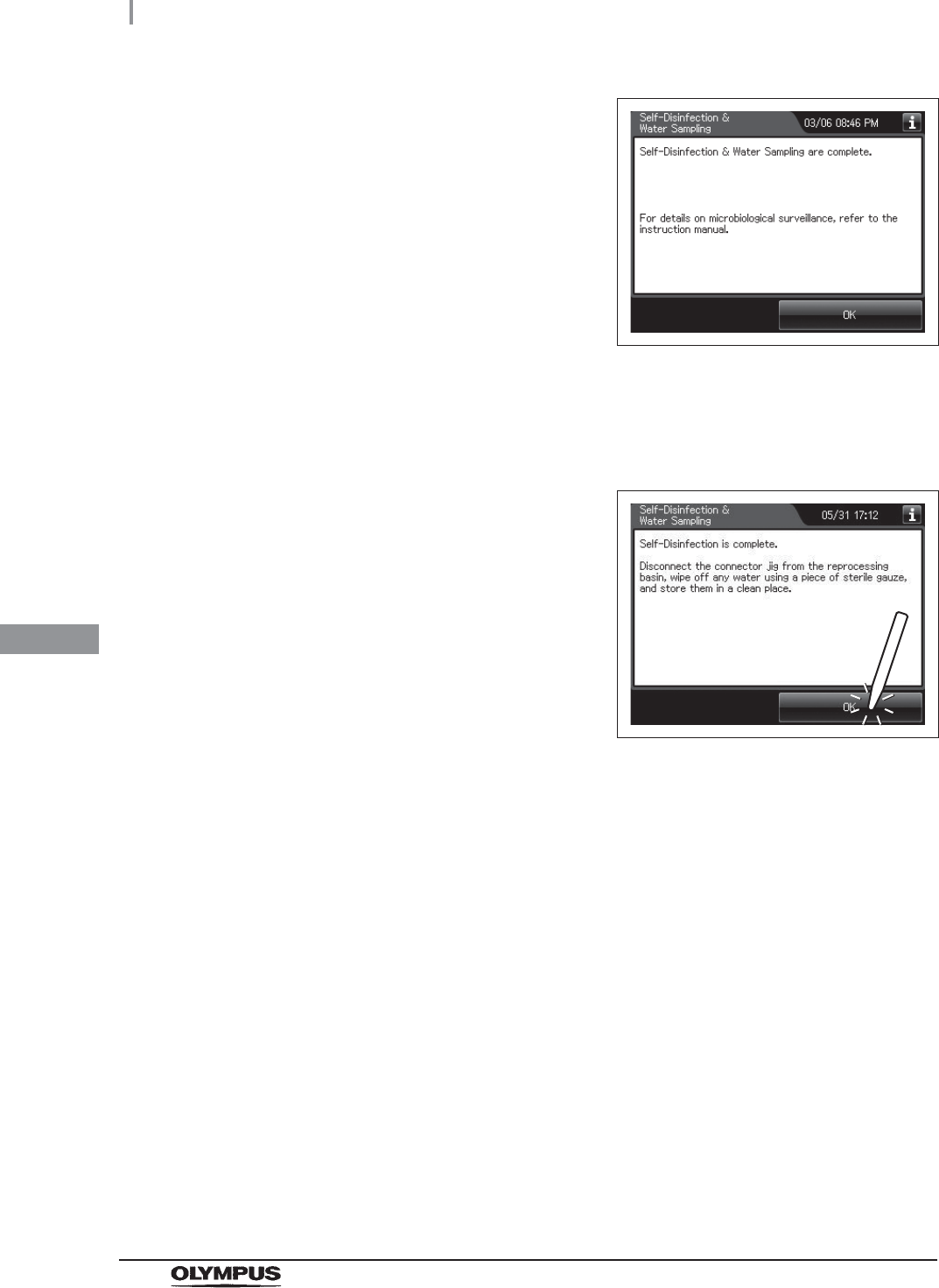
33 Press the “OK” button to complete the water
filter replacement process.
Figure 7.59
7.8 Self-disinfection and water sampling
1Checking the MRC level and entering the check result.
on page 275
2Performing the Self-disinfection and water sampling.
on page 277
3Performing the water sampling and microbiological surveillance.
on page 281
7.8 Self-disinfection and water sampling
275
OER-Elite OPERATION MANUAL
Ch.7
Required items
Table 7 . 3
NOTE
• Sterilized syringe and Sterilized bottle are needed to perform a microbiological
surveillance.
• Perform microbiological sampling of the OER-Elite rinse water quality as required
by your hospital’s policy. Also, Olympus recommends to perform microbiological
sampling of the rinse water right after performing the water supply piping
disinfection if the reprocessor has not been used for more than 14 days.
Checking the MRC level and entering the check result
Before performing the self-disinfection, check the concentration of the disinfectant solution with the test
strip, and replace the disinfectant solution if the disinfectant concentration is below the required level.
Check Required items
Sterilized syringe
Sterilized bottle
Connector jig
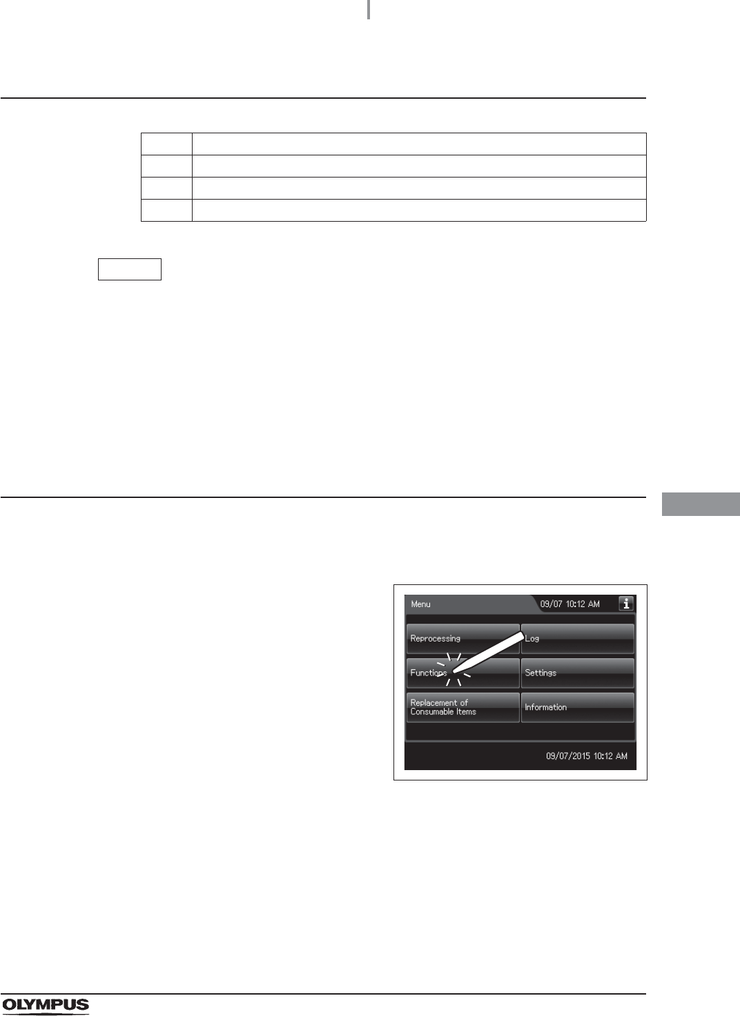
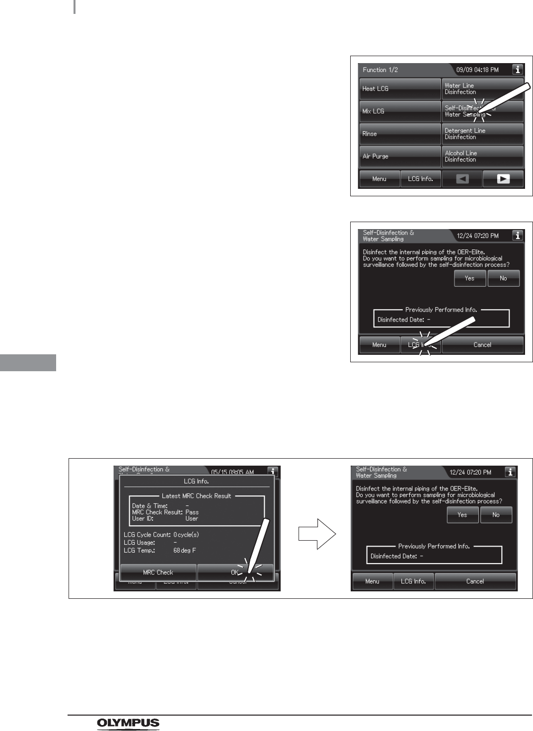
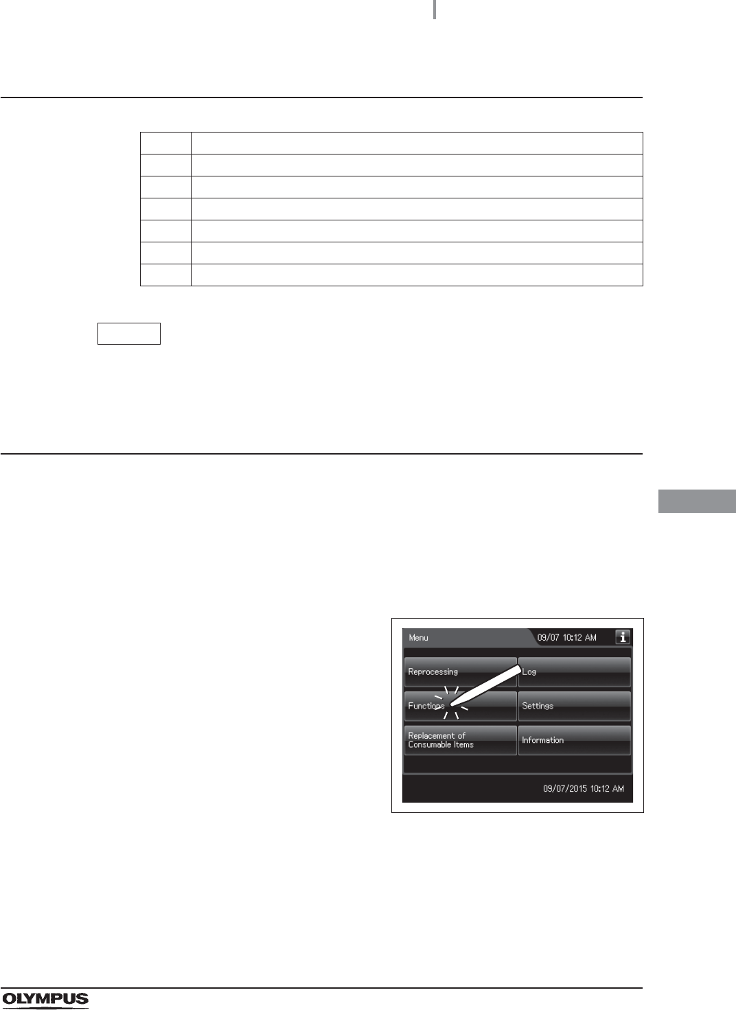
1Press the “Functions” button on the Menu
screen.
Figure 7.60
276
7.8 Self-disinfection and water sampling
OER-Elite OPERATION MANUAL
Ch.7
2Press the “Self-Disinfection & Water Sampling”
button on the Function menu.
Figure 7.61
3Press the “LCG Info.” button to display the LCG
Info. screen.
Figure 7.62
4Check the concentration of the disinfectant solution with the test strip, and enter the
check result as described in Section 3.7, “Checking the MRC level and entering the
check result”.
5Press the “OK” button to close the LCG Info screen.
Figure 7.63
7.8 Self-disinfection and water sampling
277
OER-Elite OPERATION MANUAL
Ch.7
Performing the self-disinfection
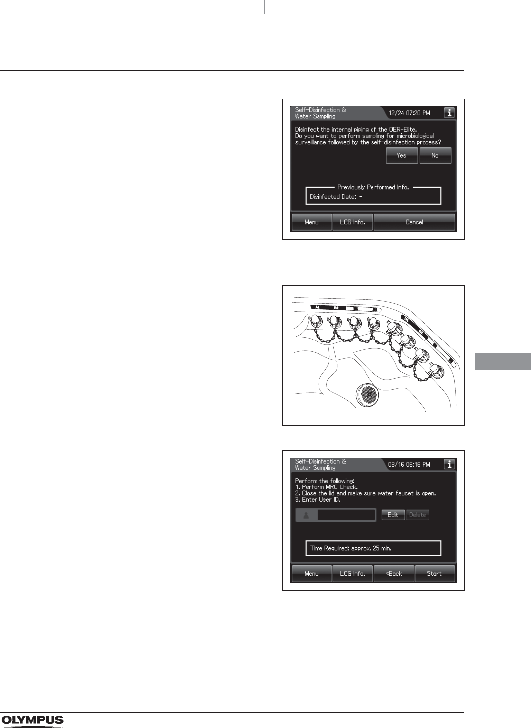
1If you want to perform sampling for
microbiological surveillance followed by the
self-disinfection process, press the “Yes”
button. Otherwise, press the “No” button.
Figure 7.64
2Step on the foot pedal to open the lid.
3Connect the connector jig to the same-colored
connector at the reprocessing basin by pushing
down on the connector jig until it clicks.
Figure 7.65
4Press the “Next” button repeatedly until the
touch screen display changes as shown
Figure 7.66.
Figure 7.66
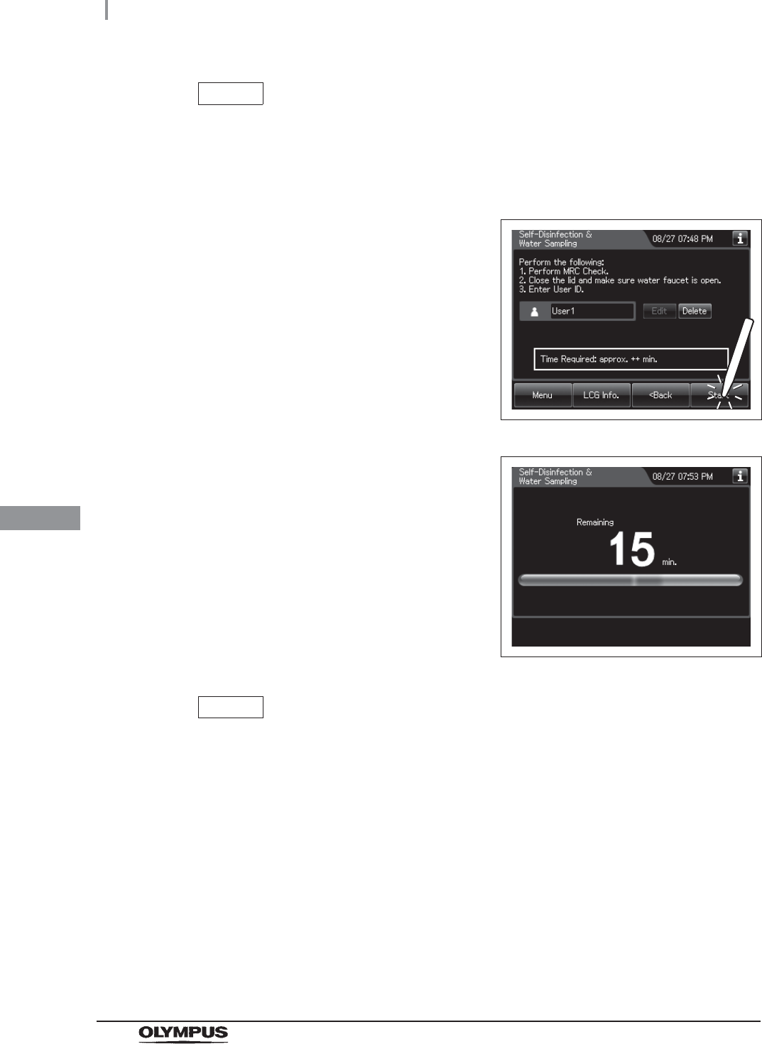
5Close the lid by pushing until it clicks.
6Make sure that the water faucet is open.
7Enter the operator's user ID. For the detailed procedures, refer to Section 3.6,
“Entering ID” (If applicable).
278
7.8 Self-disinfection and water sampling
OER-Elite OPERATION MANUAL
Ch.7
NOTE
• The input of the user ID can be omitted by modifying the user ID input setting. For
details, refer to Section 4.5, “User ID Setting”.
• If the “Delete” button is pressed, the entered ID can be deleted.
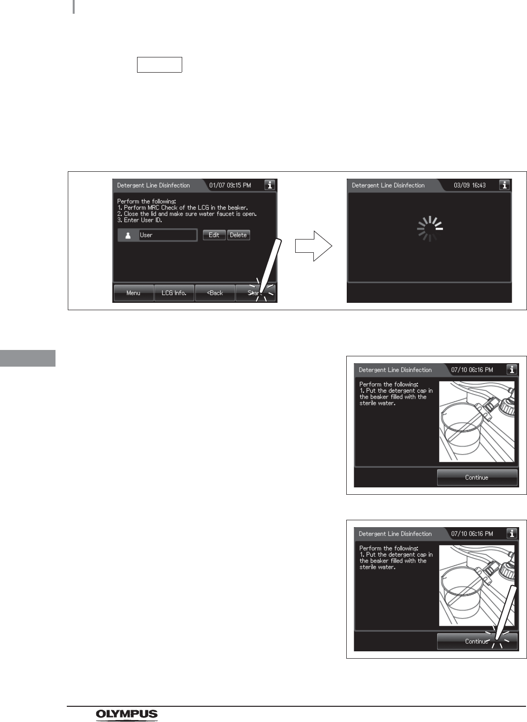
8Press the “Start” button.
Figure 7.67
9The touch screen displays the remaining time.
If sampling water was selected in the Step 1, go
to the Step 10. Otherwise, go to the step 17.
Figure 7.68
NOTE
• The cleaning, disinfection and rinse are executed in the process.
• If the temperature of the disinfectant solution is less than 20qC (68qF), it will be
heated to 20qC (68qF). During heating, the remaining time countdown and the
progress bar display stop and turn gray. After the completion of heating, the
remaining time countdown and progress bar display resume.
7.8 Self-disinfection and water sampling
279
OER-Elite OPERATION MANUAL
Ch.7
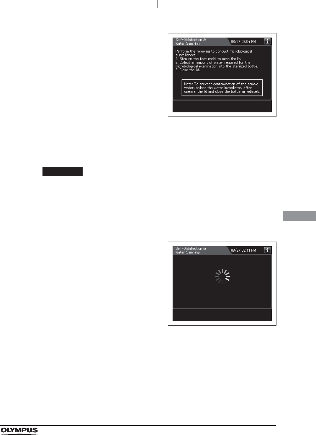
10 When the reprocessing basin is filled with
water, the buzzer beeps and the touch screen
displays the following screen.
Figure 7.69
11 Step on the foot pedal to open the lid.
12 Using a sterilized syringe, collect an amount of water for the microbiological
examination from the reprocessing basin.
CAUTION
Be sure to wear sterile gloves when collecting the water in the reprocessing basin
to prevent contamination. Do not touch the lid, the reprocessing basin, the bottle or
any area while wearing the sterile gloves. Otherwise, the collected water may
become contaminated.
13 Put the collected water in the sterile bottle.
14 Close the lid by pushing until it clicks to drain
the water in the reprocessing basin. During
draining the water, the touch screen displays
the following screen.
Figure 7.70
280
7.8 Self-disinfection and water sampling
OER-Elite OPERATION MANUAL
Ch.7
15 When discharge is completed, the buzzer
beeps and the touch screen displays the
following screen.
Figure 7.71
16 Step on the foot pedal to open the lid.
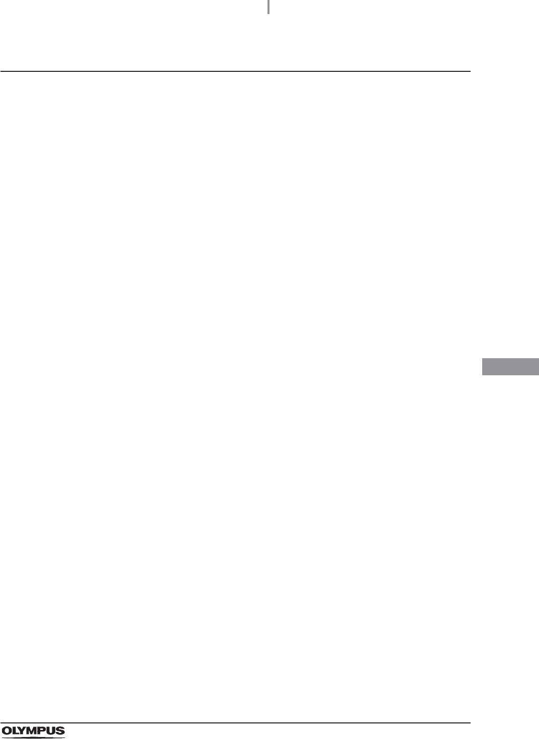
17 Disconnect the connector jig from the reprocessing basin, wipe off any water using a
piece of sterile gauze, and store them in a clean place.
18 Press the “OK” button.
Figure 7.72
7.8 Self-disinfection and water sampling
281
OER-Elite OPERATION MANUAL
Ch.7
Microbiological Surveillance
Methods for how to determine microbial level of rinse water
There are several methods for determining the microbial level. For further information on
determining the microbial level, consult other relevant guidelines or standards.
AAMI TIR34: 2014 is the latest edition of this TIR 34, one of the relevant guideline, includes the
information about available methods for how to determine microbial level of rinse water.
Acceptable microbial levels of rinse water
The acceptable microbial levels of rinse water are “bacteria-free”.
Action to be taken if microbial levels exceed acceptable level
If unacceptable bacterial levels are detected, the site should be sampled again to confirm that
unacceptable levels are a consistent finding.
If repeat testing confirms unacceptable levels, then perform decontamination process described
below to reduce the microbial level contamination.
(a) Decontamination process
If the microbial levels continue to exceed acceptable level despite the decontamination process,
an internal problem with the reprocessor or degradation of main water is suspected. In this case,
it is recommended to contact Olympus.
1Perform Self-Disinfection again. For detailed instruction, refer to Section 7.8,
“Self-disinfection and water sampling”.
2Perform Disinfection of the water supply piping. For detailed instruction, refer to
Section 4.20, “Disinfection of the water supply piping” in “Instructions-Installation
Manual”.
282
7.9 Detergent line disinfection
OER-Elite OPERATION MANUAL
Ch.7
WARNING
• When handling the disinfectant solution and detergent, carefully read the cautions
for its use to fully understand the given information and use as instructed. Particular
understanding is required for measures to be taken in case the disinfectant solution
comes into contact with your skin and eyes.
• When handling the disinfectant solution and detergent, wear appropriate personal
protective equipment to avoid direct contact with your skin and eyes or excessive
inhalation of its vapor. The disinfectant solution and its vapor may affect the human
body.
Wear personal protective equipment, such as eyewear, face mask,
moisture-resistant clothing, and chemical-resistant gloves that fit properly and are
long enough so that your skin and eyes is not exposed. All personal protective
equipment should be inspected before use and replaced periodically before it is
damaged.
• Do not block the disinfectant removal port with a finger or other objects when the
rubber cap is not attached. Otherwise, the disinfectant solution may flow out.
• To prevent peripheral devices and areas near the reprocessor from being damaged
by leaked disinfectant solution, do not leave the rubber cap off from the disinfectant
removal port.
• If disinfectant solution leaks out of the disinfectant removal port when the rubber
cap has been removed, immediately reattach the rubber cap and follow the
procedure in Section 13.2, “Troubleshooting guide”. For details, refer to “Fluid leak
the disinfectant removal port” of “Other problems and remedial actions” on
page 642. If leaking does not stop, contact Olympus.
CAUTION
To prevent spills, keep the detergent tanks upright.
7.9 Detergent line disinfection
7.9 Detergent line disinfection
283
OER-Elite OPERATION MANUAL
Ch.7
Required items
Table 7 . 4
NOTE
For the test strip, refer to Section 2.8, “Consumable accessories (Optional)”.
Detergent line disinfection
Before disinfecting, disinfectant solution temperature is confirmed. When disinfectant solution
temperature is below 20qC (68qF), execute the Heat LCG. For detail of Heat LCG, refer to Section 7.2,
“Heat LCG”.
Check Required items
FDA-cleared chemical indicator (test strip)
Drain connector (should be dry)
Clean cloth
Two beakers with 300 ml or larger capacity (e.g. beaker)
Disinfectant solution: approximately 120 ml
Sterile water: more than 300 ml
1Close the lid by pushing until it clicks.
2Make sure that the water faucet is open.
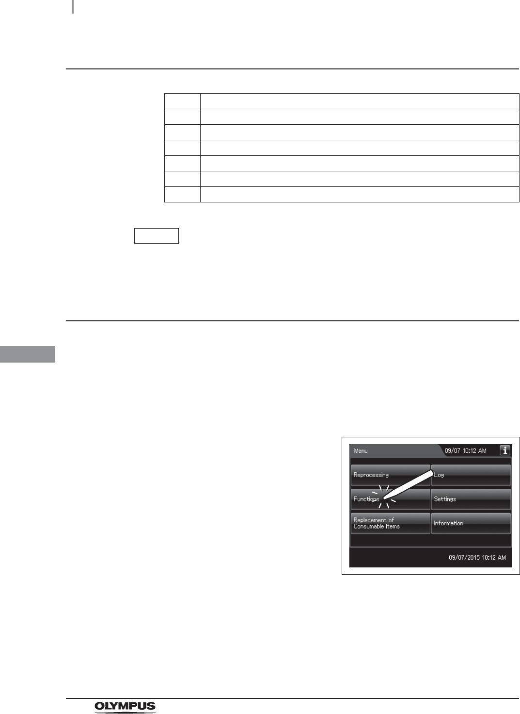
3Press the “Functions” button on the Menu
screen.
Figure 7.73
284
7.9 Detergent line disinfection
OER-Elite OPERATION MANUAL
Ch.7
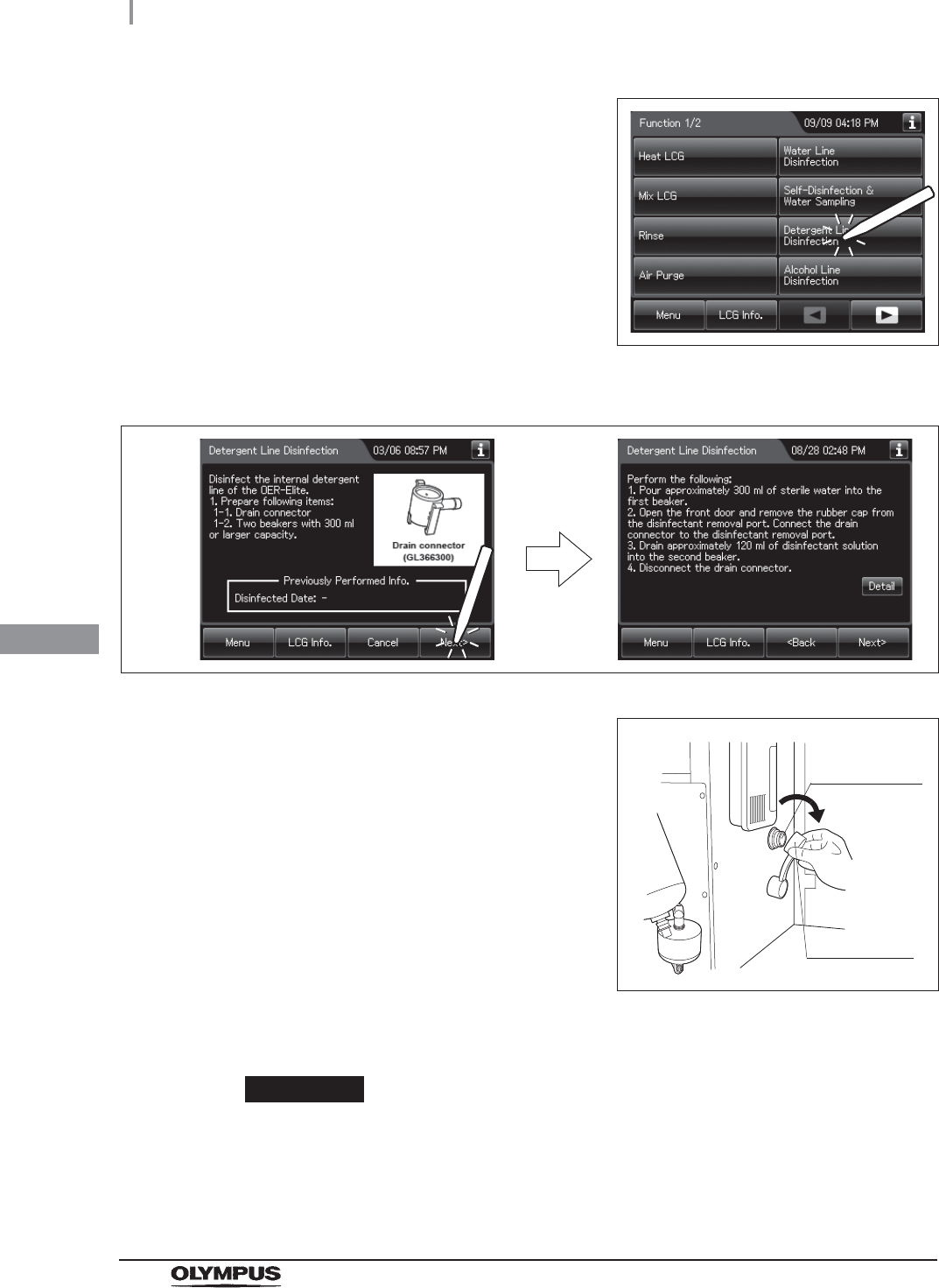
4Press the “Detergent Line Disinfection” button.
Figure 7.74
5Press the “Next” button.
Figure 7.75
6Push [PUSH] on the front door to open the front
door. Remove the rubber cap from the
disinfectant removal port.
Figure 7.76
7Push the drain connector into the disinfectant removal port until it clicks.
WARNING
When connecting the drain connector to the disinfectant removal port, do not push
on the connector’s valve. Otherwise, disinfectant solution will leak out of it.
Disinfectant
removal port
Rubber cap
7.9 Detergent line disinfection
285
OER-Elite OPERATION MANUAL
Ch.7
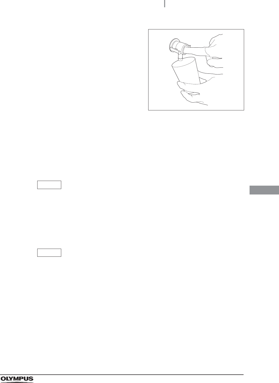
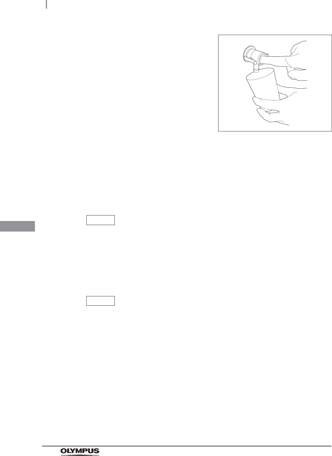
8Place a beaker below the drain connector, push
the connector’s valve, and collect
approximately 120 ml of disinfectant solution.
Figure 7.77
9Place the prepared cloth under the drain connector, hold the lock lever, and slowly
disconnect the connector. Wipe off any disinfectant solution if it leaks.
10 Wipe the disinfectant removal port with a clean cloth and put the rubber cap back on.
Rinse the drain LCG connector thoroughly in running water, dry it thoroughly and
store in a clean place.
11 Close the front door.
NOTE
The front door cannot be closed unless the rubber cap is attached.
12 Check the disinfectant solution concentration level in the beaker by using the test strip
while taking care not to inhale the disinfectant solution vapor. If the concentration is
below its MRC, replace the disinfectant solution as described in Section 8.2,
“Replacing the disinfectant solution”.
NOTE
In the detergent line disinfection, always check the disinfectant concentration level
in the beaker.
286
7.9 Detergent line disinfection
OER-Elite OPERATION MANUAL
Ch.7
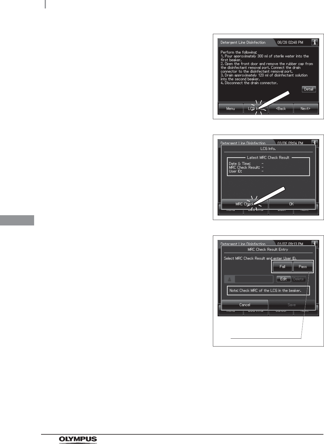
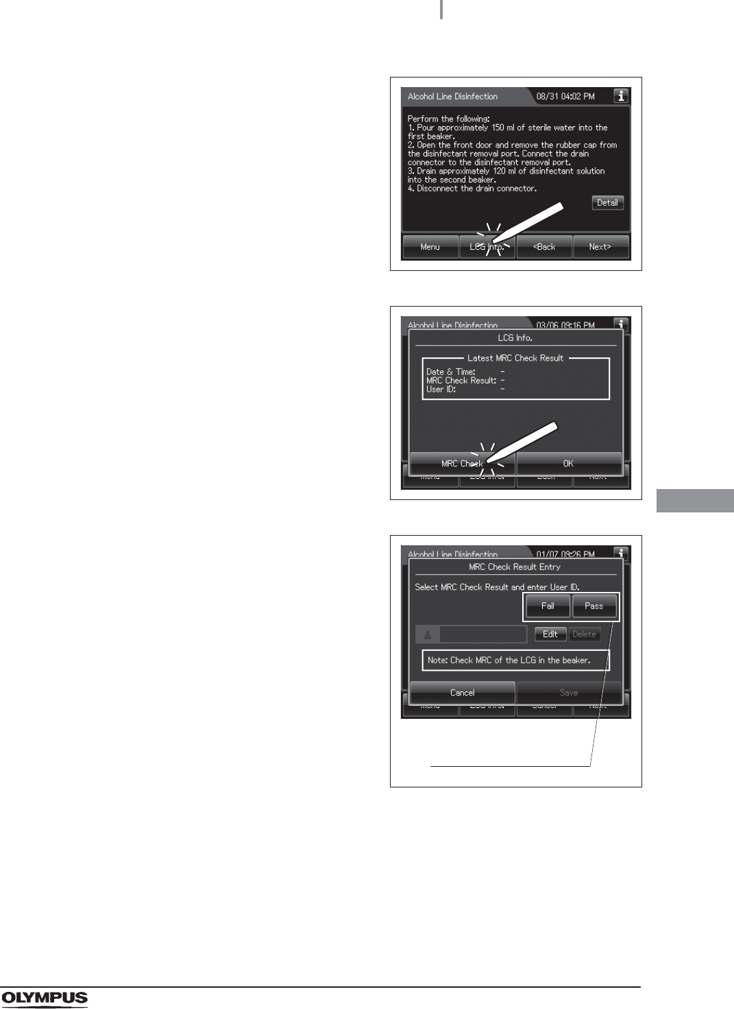
13 Press the “LCG Info” button.
Figure 7.78
14 Press the “MRC Check” button.
Figure 7.79
15 Input the MRC Check Result.
Figure 7.80
16 Input the operator’s user ID. For the detailed procedure, refer to Section 3.6, “Entering
ID” (If applicable).
Select the result of check
using the test strip.
7.9 Detergent line disinfection
287
OER-Elite OPERATION MANUAL
Ch.7
NOTE
• The input of the user ID can be omitted by modifying the user ID input setting. For
details, refer to Section 4.5, “User ID Setting”.
• If the “Delete” button is pressed, the entered ID can be deleted.
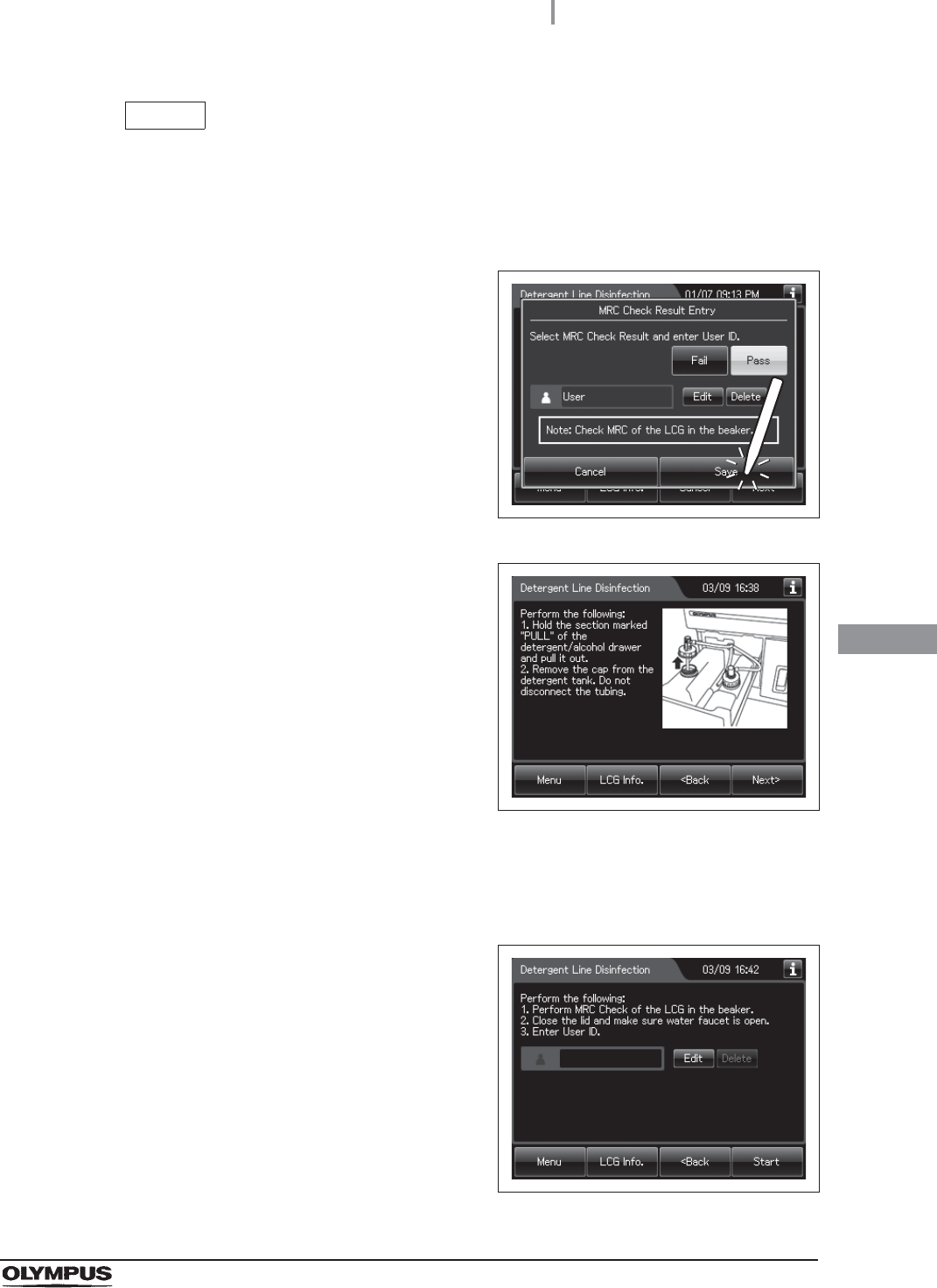
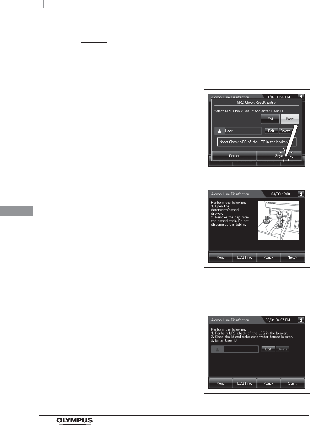
17 Press the “Save” button.
Figure 7.81
18 Press the “OK” button and the “Next” button
repeatedly until the touch screen display
changes as shown Figure 7.82.
Figure 7.82
19 Pull out the detergent/alcohol drawer.
Detach the detergent tank cap to which the tube is connected. (Do not disconnect the
connector.)
20 Press the “Next” button. Input the operator’s
user ID. For the detailed procedure, refer to
Section 3.6, “Entering ID” (If applicable).
Figure 7.83
288
7.9 Detergent line disinfection
OER-Elite OPERATION MANUAL
Ch.7
NOTE
• The input of the user ID can be omitted by modifying the user ID input setting. For
details, refer to Section 4.5, “User ID Setting”.
• If the “Delete” button is pressed, the entered ID can be deleted.
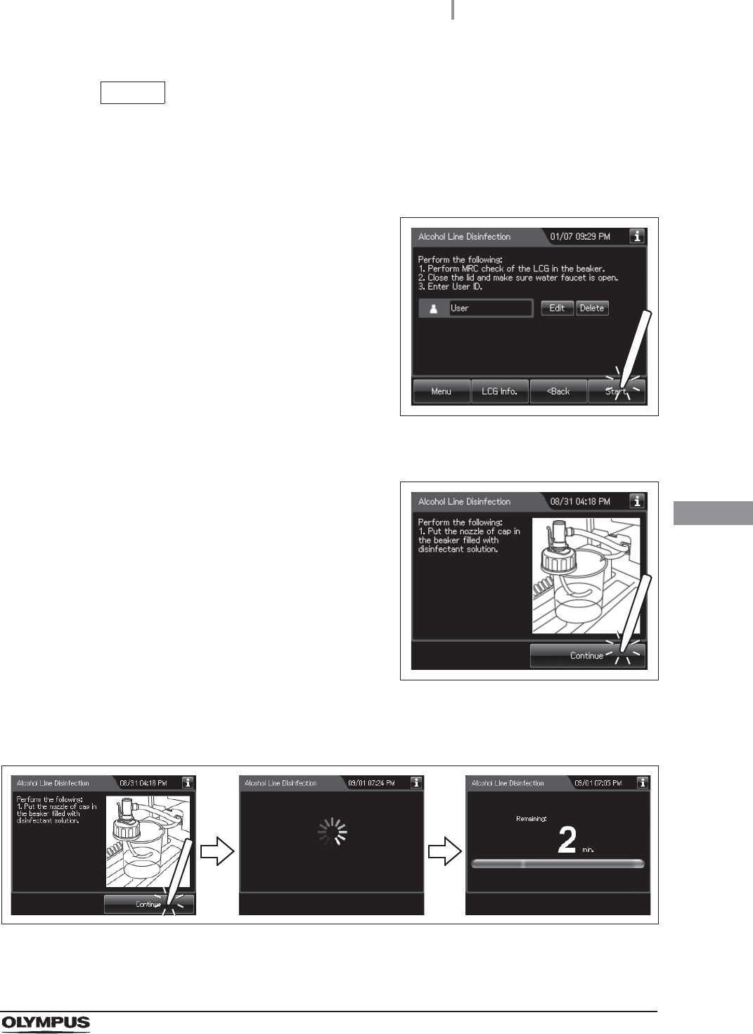
21 Press the “Start” button. The drain of detergent solution from the detergent line starts.
Figure 7.84
22 Pour approximately 150 ml of sterile water into another beaker.
23 When the touch screen display changes as
shown Figure 7.85, put the nozzle of detergent
cap in the beaker filled with the sterile water.
Figure 7.85
24 Press the “Continue” button. The rinse of the
detergent lines starts. Wait for a few seconds.
Figure 7.86
7.9 Detergent line disinfection
289
OER-Elite OPERATION MANUAL
Ch.7
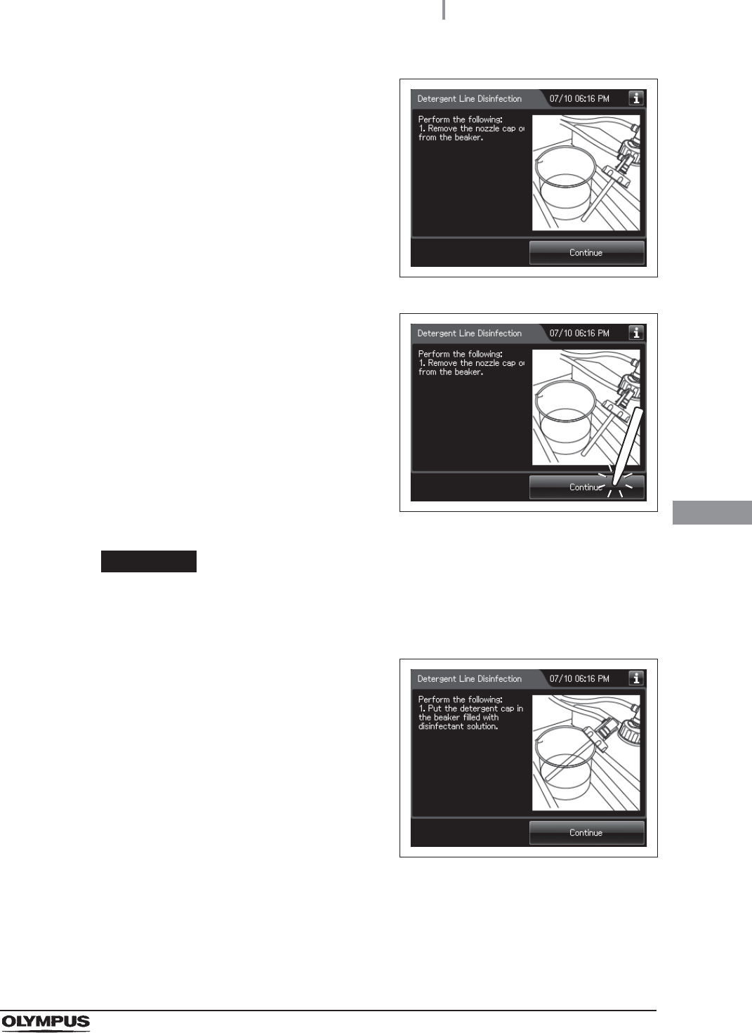
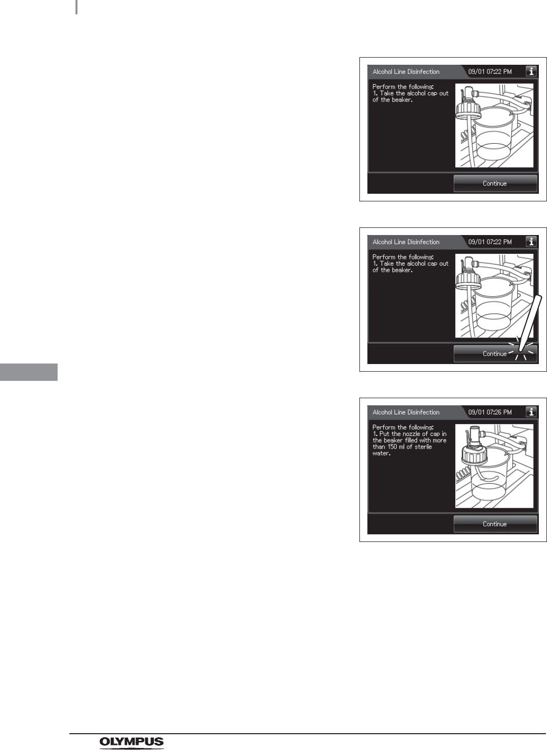
25 When the touch screen display changes as
shown Figure 7.87, take the nozzle of
detergent cap out of the beaker.
Figure 7.87
26 Press the “Continue” button and wait for a few
seconds.
Figure 7.88
CAUTION
Do not block the tube-shaped tip of the detergent tank cap. Otherwise, the fluid
inside the detergent line may not be able to be drained.
27 When the touch screen display changes as
shown Figure 7.89, put the nozzle of the
detergent cap in the beaker filled with the
disinfectant solution.
Figure 7.89
290
7.9 Detergent line disinfection
OER-Elite OPERATION MANUAL
Ch.7
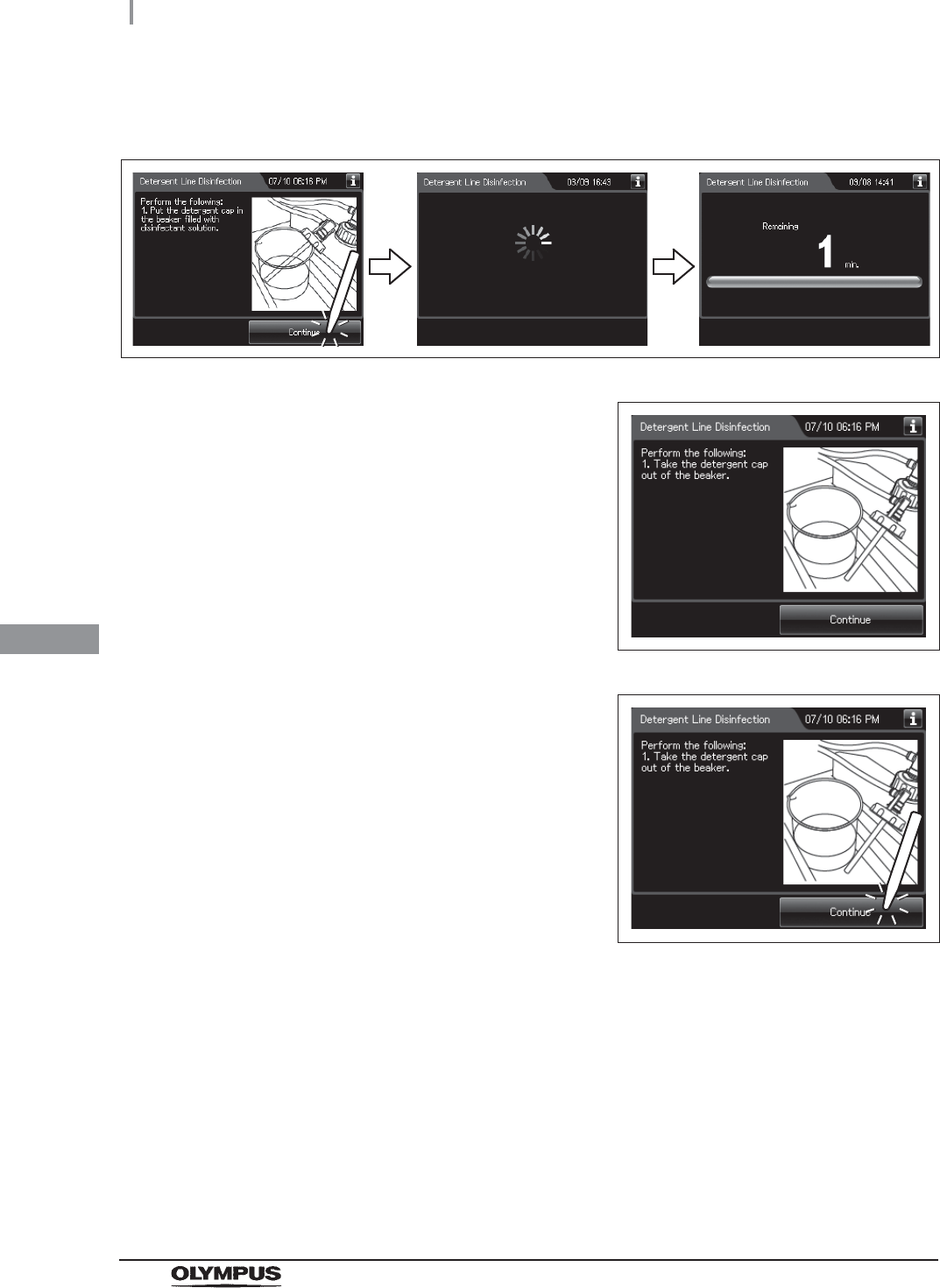
28 Press the “Continue” button. The disinfection of the detergent lines starts and the
touch screen displays the remaining disinfectant time. Wait a few minutes.
Figure 7.90
29 When the touch screen display changes as
shown Figure 7.91, take the nozzle of
detergent cap out of the beaker.
Figure 7.91
30 Press the “Continue” button and wait for a few
seconds.
Figure 7.92
7.9 Detergent line disinfection
291
OER-Elite OPERATION MANUAL
Ch.7
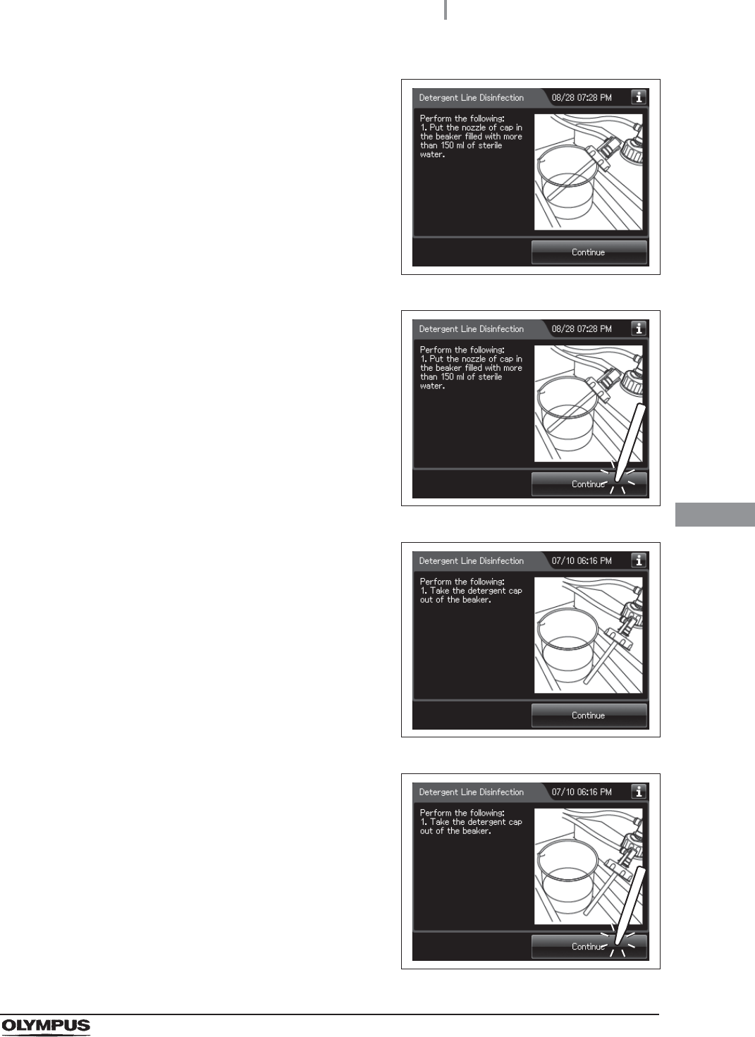
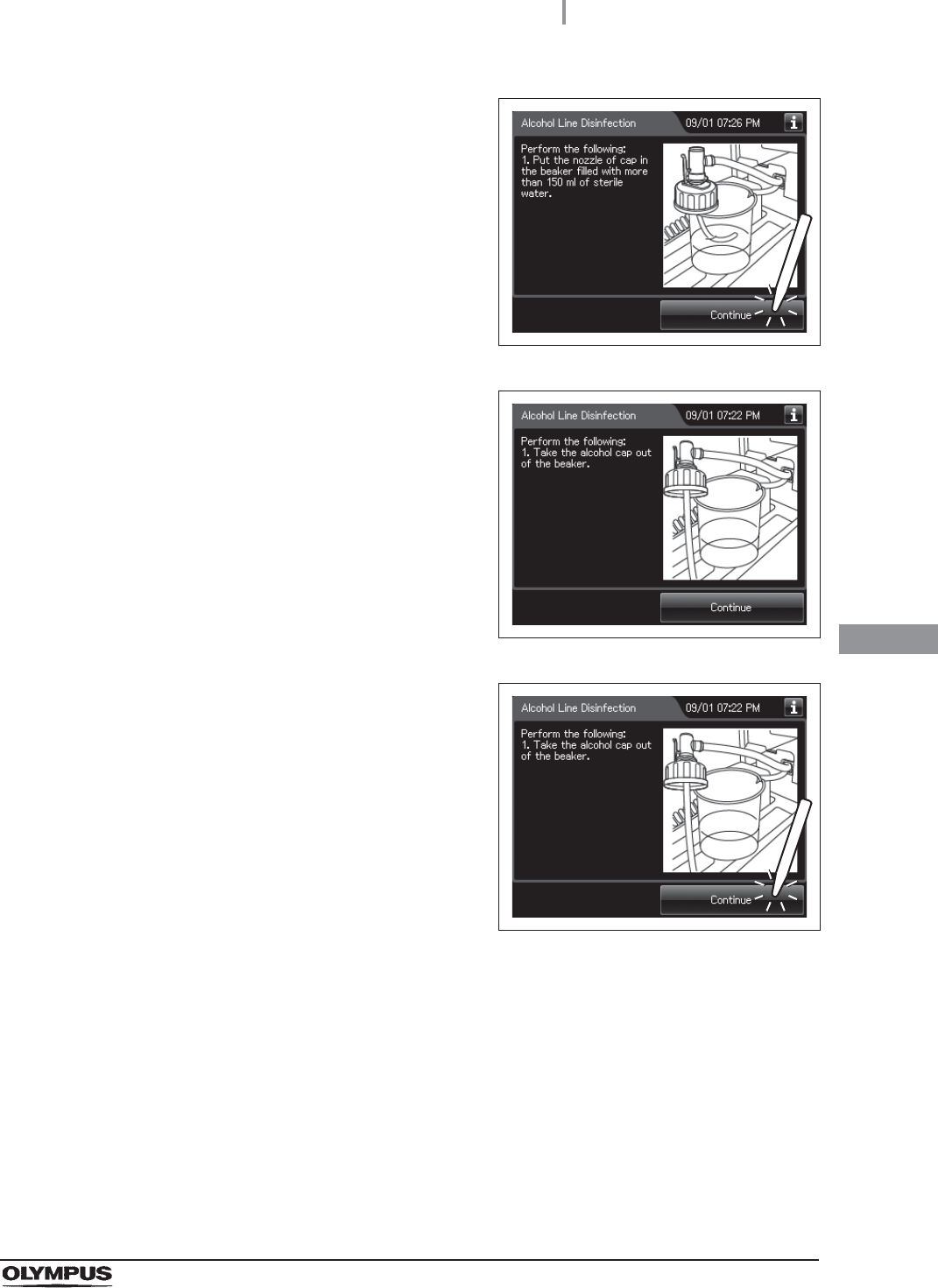
31 When the touch screen display changes as
shown Figure 7.93. Put the nozzle of detergent
cap in the beaker filled with more than 150 ml
of sterile water.
Figure 7.93
32 Press the “Continue” button. Rinse of the
detergent lines starts.
Figure 7.94
33 When the touch screen display changes as
shown Figure 7.95, take the nozzle of
detergent cap out of the beaker.
Figure 7.95
34 Press the “Continue” button. Draining of the
detergent lines starts.
Figure 7.96
292
7.9 Detergent line disinfection
OER-Elite OPERATION MANUAL
Ch.7
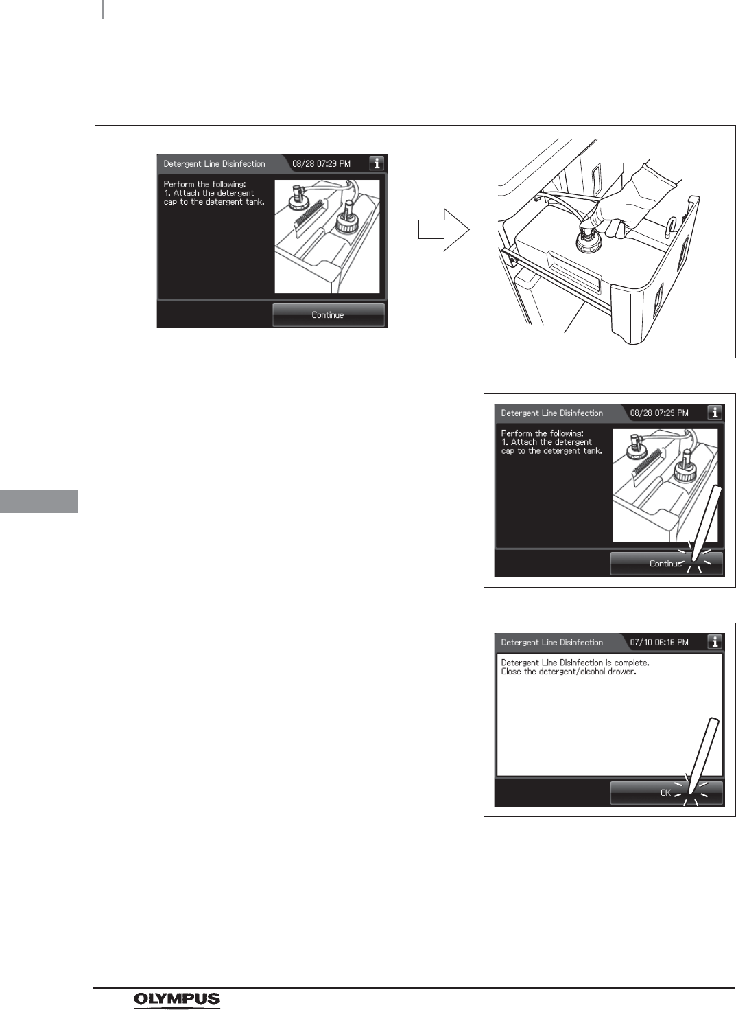
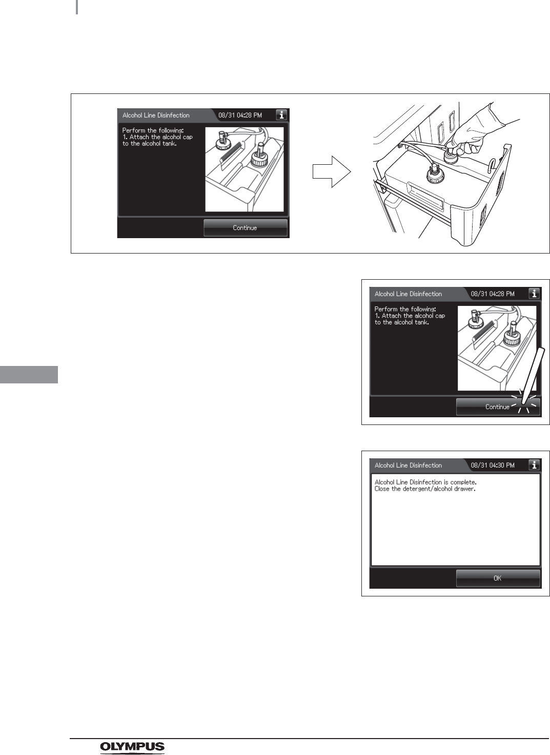
35 When the touch screen display changes as shown below, attach the detergent cap to
the detergent tank.
Figure 7.97
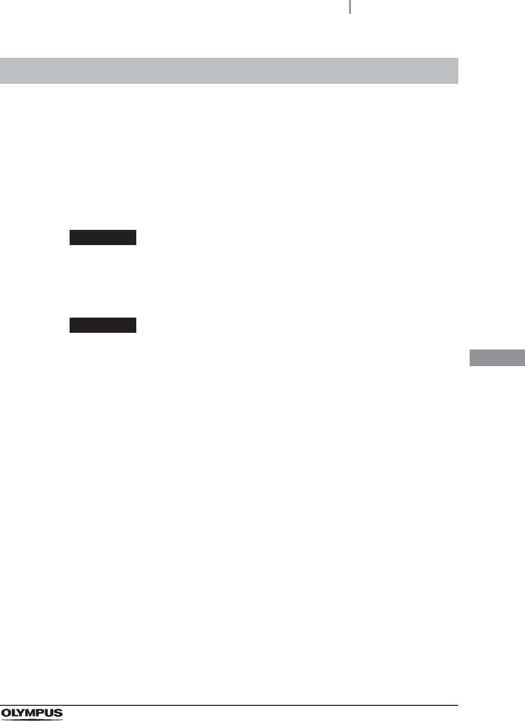
36 Press the “Continue” button. Injection of
detergent in the detergent lines starts and the
water in the reprocessing basin is drained.
Figure 7.98
37 Press the “OK” button to finish disinfection of
the detergent lines.
Figure 7.99
7.10 Alcohol line disinfection
293
OER-Elite OPERATION MANUAL
Ch.7
WARNING
• When handling the disinfectant solution and alcohol, carefully read the cautions for
its use to fully understand the given information and use as instructed. Particular
understanding is required for measures to be taken in case the disinfectant solution
comes into contact with your skin and eyes.
• When handling the disinfectant solution and alcohol, wear appropriate personal
protective equipment to avoid direct contact with your skin and eyes or excessive
inhalation of its vapor. The disinfectant solution and its vapor may affect the human
body.
Wear personal protective equipment, such as eyewear, face mask,
moisture-resistant clothing, and chemical-resistant gloves that fit properly and are
long enough so that your skin and eyes is not exposed. All personal protective
equipment should be inspected before use and replaced periodically before it is
damaged.
• Do not block the disinfectant removal port with a finger or other objects when the
rubber cap is not attached. Otherwise, the disinfectant solution may flow out.
• To prevent peripheral devices and areas near the reprocessor from being damaged
by leaked disinfectant solution, do not leave the rubber cap off from the disinfectant
removal port except when connecting the drain connector to the disinfectant
removal port.
• If disinfectant solution leaks out of the disinfectant removal port when the rubber
cap has been removed, immediately reattach the rubber cap and follow the
procedure in Section 13.2, “Troubleshooting guide”. For details, refer to “Fluid leak
the disinfectant removal port” of “Other problems and remedial actions” on
page 642. If leaking does not stop, contact Olympus.
• Make sure to attach the connector jigs. Otherwise, the disinfection of the alcohol
supply line may not be effective.
• After disinfecting the alcohol supply line, always rinse it thoroughly. Otherwise,
disinfectant solution may remain on the endoscope following reprocessing and
pose a patient safety risk.
CAUTION
To prevent spills, keep the alcohol tanks upright.
7.10 Alcohol line disinfection
294
7.10 Alcohol line disinfection
OER-Elite OPERATION MANUAL
Ch.7
Required items
Table 7.5
NOTE
For the test strip, refer to Section 2.8, “Consumable accessories (Optional)”.
Alcohol line disinfection
Before disinfecting, disinfectant solution temperature is confirmed. When disinfectant solution
temperature is below 20qC (68qF), execute the Heat LCG. For detail of Heat LCG, refer to Section 7.2,
“Heat LCG”.
Check Required items
FDA-cleared chemical indicator (test strip)
Drain connector (should be dry)
Clean cloth
Two beakers with 200 ml or larger capacity (e.g. beaker)
Disinfectant solution: approximately 120 ml
Sterile water: more than 150 ml
1Close the lid by pushing until it clicks.
2Make sure that the water faucet is open.
3Press the “Functions” button on the Menu
screen.
Figure 7.100
7.10 Alcohol line disinfection
295
OER-Elite OPERATION MANUAL
Ch.7
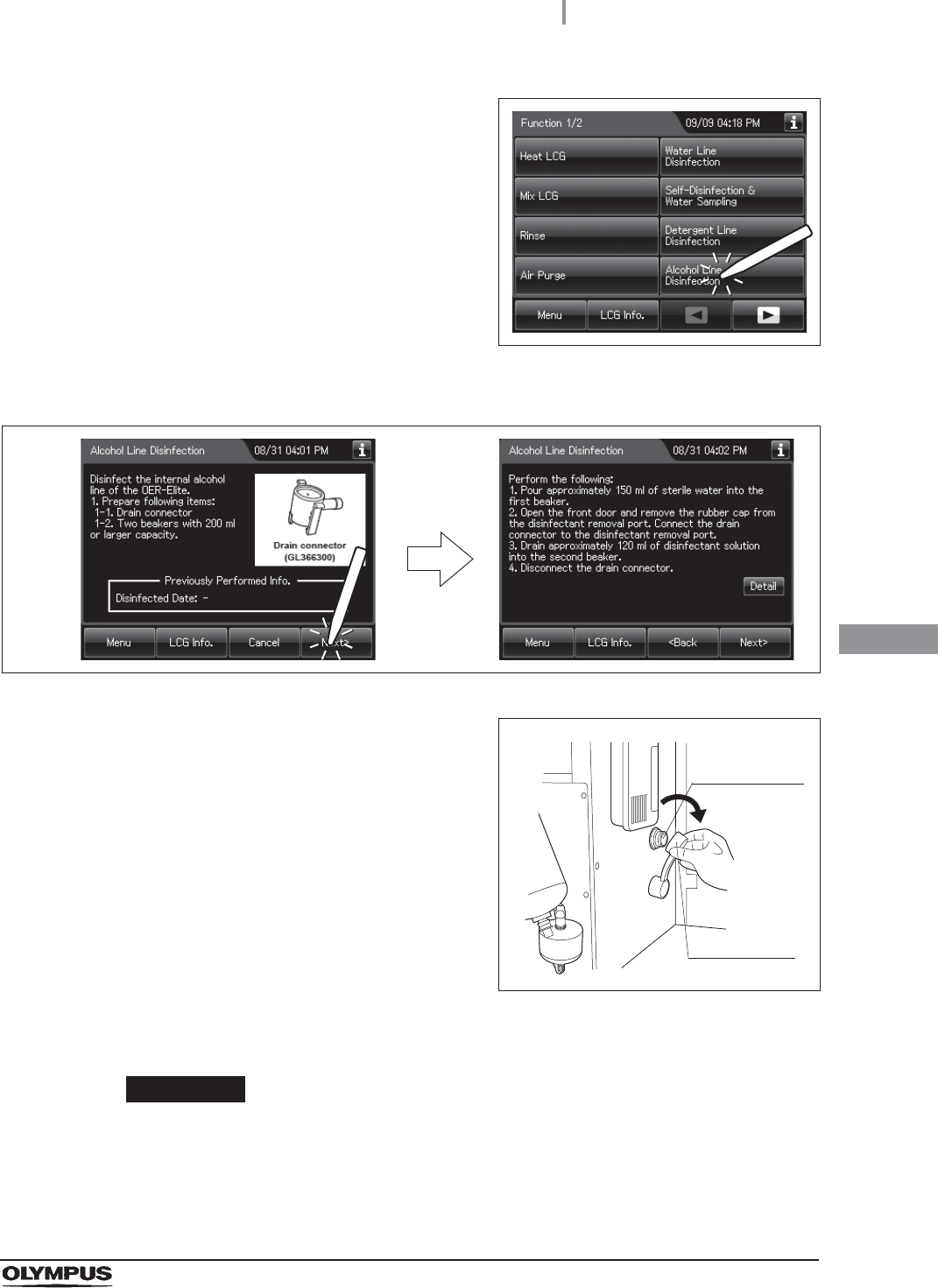
4Press the “Alcohol Line Disinfection” button.
Figure 7.101
5Press the “Next” button.
Figure 7.102
6Push [PUSH] on the front door to open the front
door. Remove the rubber cap from the
disinfectant removal port.
Figure 7.103
7Push the drain connector into the disinfectant removal port until it clicks.
WARNING
When connecting the drain connector to the disinfectant removal port, do not push
on the connector’s valve. Otherwise, disinfectant solution will leak out of it.
Disinfectant
removal port
Rubber cap
296
7.10 Alcohol line disinfection
OER-Elite OPERATION MANUAL
Ch.7
8Place a beaker below the drain connector, push
the connector’s valve, and collect
approximately 120 ml of disinfectant solution.
Figure 7.104
9Place the prepared cloth under the drain connector, hold the lock lever, and slowly
disconnect the connector. Wipe off any disinfectant solution if it leaks.
10 Wipe the disinfectant removal port with a clean cloth and put the rubber cap back on.
Rinse the drain LCG connector thoroughly in running water, dry it thoroughly and
store in a clean place.
11 Close the front door.
NOTE
The front door cannot be closed unless the rubber cap is attached.
12 Check the disinfectant solution concentration level in the beaker by using the test strip
while taking care not to inhale the disinfectant solution vapor. If the concentration is
below its MRC, replace the disinfectant solution as described in Section 8.2,
“Replacing the disinfectant solution”.
NOTE
In the alcohol line disinfection, always check the disinfectant concentration level in
the beaker.
7.10 Alcohol line disinfection
297
OER-Elite OPERATION MANUAL
Ch.7
13 Press the “LCG Info” button.
Figure 7.105
14 Press the “MRC Check” button.
Figure 7.106
15 Input the MRC Check Result.
Figure 7.107
16 Input the operator’s user ID. For the detailed procedure, refer to Section 3.6, “Entering
ID” (If applicable).
Select the result of check
using the test strip.
298
7.10 Alcohol line disinfection
OER-Elite OPERATION MANUAL
Ch.7
NOTE
• The input of the user ID can be omitted by modifying the user ID input setting. For
details, refer to Section 4.5, “User ID Setting”.
• If the “Delete” button is pressed, the entered ID can be deleted.
17 Press the “Save” button.
Figure 7.108
18 Press the “OK” button and the “Next” button
repeatedly until the touch screen display
changes as shown Figure 7.109.
Figure 7.109
19 Pull out the detergent/alcohol drawer.
Detach the alcohol tank cap to which the tube is connected. (Do not disconnect the
connector.)
20 Press the “Next” button. Input the operator’s
user ID. For the detailed procedure, refer to
Section 3.6, “Entering ID” (If applicable).
Figure 7.110
7.10 Alcohol line disinfection
299
OER-Elite OPERATION MANUAL
Ch.7
NOTE
• The input of the user ID can be omitted by modifying the user ID input setting. For
details, refer to Section 4.5, “User ID Setting”.
• If the “Delete” button is pressed, the entered ID can be deleted.
21 Press the “Start” button. The drain of alcohol
from the alcohol line starts.
Figure 7.111
22 Pour approximately 120 ml of disinfectant solution into another beaker.
23 When the touch screen display changes as
shown Figure 7.112, put the nozzle of alcohol
cap in the beaker filled the disinfectant solution.
Figure 7.112
24 Press the “Continue” button. The disinfection of the alcohol lines starts and the touch
screen displays the remaining disinfectant time. Wait a few minutes.
Figure 7.113
300
7.10 Alcohol line disinfection
OER-Elite OPERATION MANUAL
Ch.7
25 When the touch screen display changes as
shown Figure 7.114, take the nozzle of the
alcohol cap out of the beaker.
Figure 7.114
26 Press the “Continue” button and wait for a few
seconds.
Figure 7.115
27 When the touch screen display changes as
shown Figure 7.116, Put the nozzle of alcohol
cap in the beaker filled with more than 150ml of
sterile water.
Figure 7.116
7.10 Alcohol line disinfection
301
OER-Elite OPERATION MANUAL
Ch.7
28 Press the “Continue” button. Rinse of the
alcohol lines starts.
Figure 7.117
29 When the touch screen display changes as
shown Figure 7.118, take the nozzle of alcohol
cap out of the beaker.
Figure 7.118
30 Press the “Continue” button. Draining of the
alcohol lines starts.
Figure 7.119
302
7.10 Alcohol line disinfection
OER-Elite OPERATION MANUAL
Ch.7
31 When the touch screen display changes as shown Figure 7.120, attach the nozzle of
alcohol cap to the alcohol tank.
Figure 7.120
32 Press the “Continue” button. Injection of alcohol
in the alcohol lines starts and the water in the
reprocessing basin is drained.
Figure 7.121
33 Press the “OK” button to finish disinfection of
the alcohol lines.
Figure 7.122
7.11 Manual leak test
303
OER-Elite OPERATION MANUAL
Ch.7
The manual leak test confirmations are linked to the scope ID's reprocessing records or leaking scope
decontamination records. To prevent endoscope damage due to water invasion, always check for
leaks before reprocessing the endoscope to ensure that you discover any irregularity, such as small
holes, at an early stage. The leak test consists of filling the reprocessing basin with water and
observing the endoscope’s outer surfaces and the leak test air tube to ensure that air bubbles are not
produced continuously from any point and that there is no sound of air leakage. Refer to the “List of
Compatible Endoscopes/Connecting Tubes <OER-Elite>” for the necessary tubing required for proper
leakage testing.
WARNING
When reprocessing the endoscopes after the manual leak test, be sure to
straighten their bending sections. Otherwise, the reprocessing may become
insufficient.
CAUTION
• The leak test air tube will disconnect easily if it is not attached properly or if the lock
lever is degraded. Air cannot be fed properly if the leak test air tube is bent. In
these cases, an accurate leak test is not possible.
• Ensure that each leak test air tube is free of irregularity such as a crack, fissure,
scratch, or contamination. If an abnormal leak test air tube is used, the endoscope
may fail or the leak test will be erroneous. Replace it with a new tube and retry the
Manual Leak test.
• Do not connect the leak test air tube if the inside of the tube, the endoscope’s
venting connector, or the reprocessor’s leak test connector is wet. Doing so could
allow water to get inside the endoscope and cause the endoscope to malfunction.
• Do not perform the manual leak test while connecting tubes are connected.
Otherwise, irregularity in the endoscope may not be detected.
• Do not disconnect the leak test air tubes in the middle of the process or while the
water is remaining in the reprocessing basin. Otherwise, the endoscopes may fail
due to the fluid entering inside them or the retention of the pressurized status inside
them.
• Do not leave an unused leak test air tube in the basin. Otherwise, water penetrating
inside the leak test air tube may cause malfunctions of the reprocessor.
7.11 Manual leak test
304
7.11 Manual leak test
OER-Elite OPERATION MANUAL
Ch.7
CAUTION
• If air bubbles are produced continuously from an endoscope or leak test air tube
during a leak test, press the Stop button on the touch screen to discontinue the leak
test process, remove the scope or tube from the reprocessing basin and contact
Olympus. Otherwise, water may penetrate the scope via the area around where the
bubbles are exiting.
NOTE
During leak test, the angulating section’s covering may expand. This is not a
malfunction.
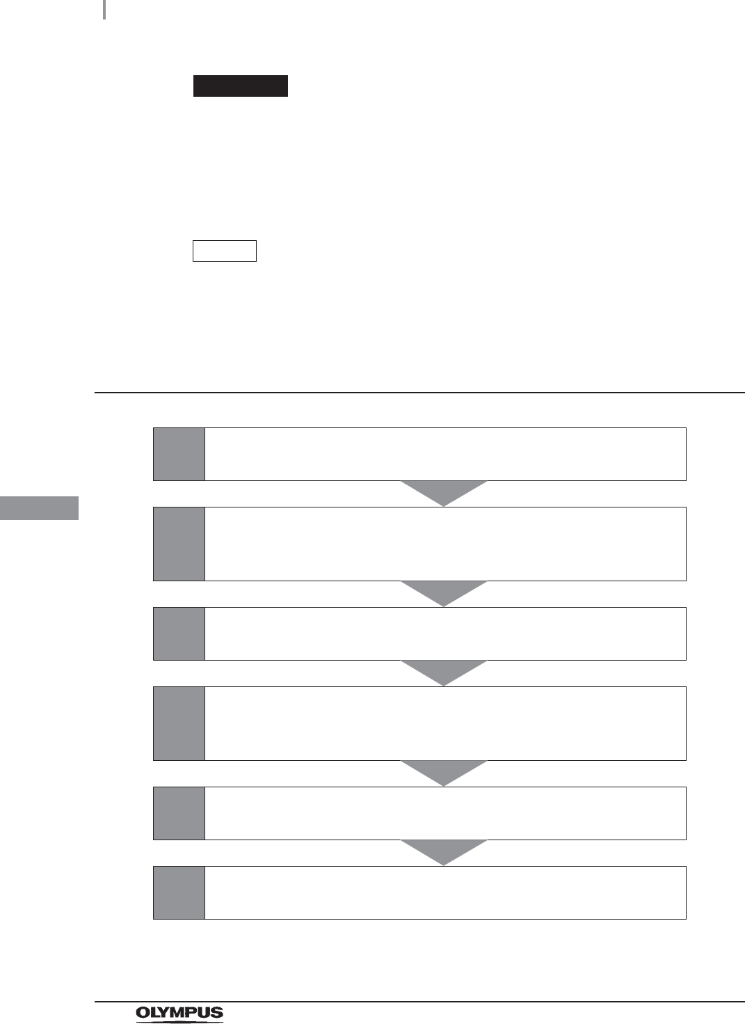
Workflow of manual leak test
1Input scope ID of first endoscope.
on page 305
2
Loading of first endoscope in reprocessing basin and attaching
the connecting tubes.
on page 306
3Input scope ID of second endoscope.
on page 307
4
Loading of second endoscope in reprocessing basin and
attaching the connecting tubes.
on page 307
5Performing manual leak test.
on page 307
6Print format.
on page 309
7.11 Manual leak test
305
OER-Elite OPERATION MANUAL
Ch.7
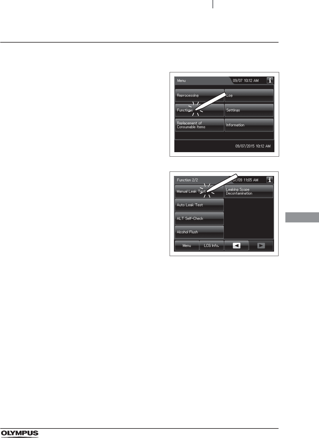
Performing manual leak test
1Make sure that the water faucet is open.
2Press the “Functions” on the Menu screen.
Figure 7.123
3Press the “Manual Leak Test” button on the 2nd
page of the Functions menu.
Figure 7.124
4Step on the foot pedal to open the lid.
5Input the Scope IDs. For the detailed procedures, refer to Section 3.6, “Entering ID” (If
applicable).
306
7.11 Manual leak test
OER-Elite OPERATION MANUAL
Ch.7
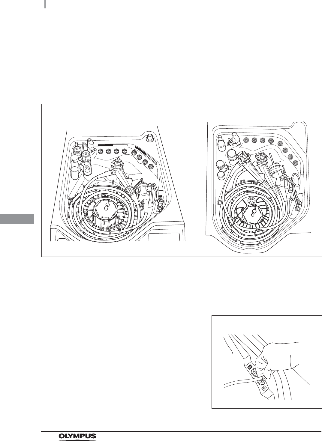
6Place the endoscope carefully, checking the following:
The distal end of the insertion tube is straight.
The distal end of the insertion tube is not on or beneath another object.
The leak test air tube is not twisted.
The endoscope is not contacting the lid.
The connecting tube is not connected.
Figure 7.125
7Wipe the venting connector of the endoscope or that of the waterproof cap with a
clean cloth immersed in 70% ethyl alcohol or 70% isopropyl alcohol.
8If the leak test connector E1/E2 in the reprocessing basin is wet, wipe the entire
connector with a clean cloth.
9Connect the MAJ-2127 leak test air tubes to the
venting connector or the water resistant cap of
the first endoscope and leak test connector E1
in the reprocessing basin. When placing the
second endoscope, connect the MAJ-2127
leak test air tubes to the second endoscope
and leak test connector E2 in the reprocessing
basin.
Figure 7.126
When reprocessing one endoscope When reprocessing two endoscope
First endoscope
7.11 Manual leak test
307
OER-Elite OPERATION MANUAL
Ch.7
10 Place the second endoscope, same as from Step 1 through 9 of the first endoscope.
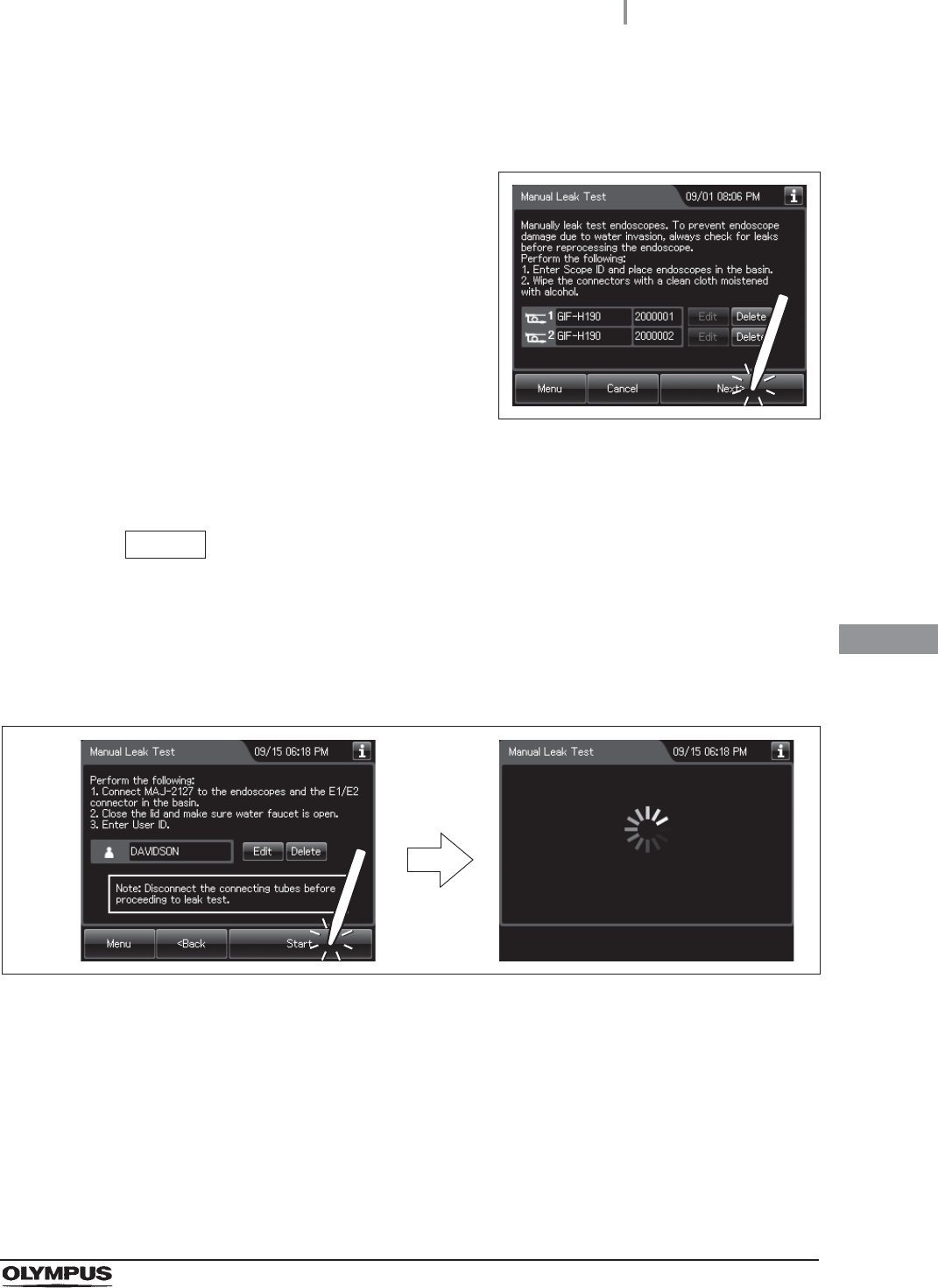
11 Close the lid by pushing until it clicks.
12 Press the “Next” button.
Figure 7.127
13 Input the operator’s user ID. For the detailed procedures, refer to Section 3.6,
“Entering ID”. (If applicable)
NOTE
The user ID input can be omitted according to the user ID input setting. For details,
refer to Section 4.5, “User ID Setting”.
14 Press the “Start” button. Water supply starts and the touch screen changes as shown
below.
Figure 7.128
308
7.11 Manual leak test
OER-Elite OPERATION MANUAL
Ch.7
15 When the water supply completes, the
reprocessor generates three buzzer beeps and
unlock the lid.
Figure 7.129
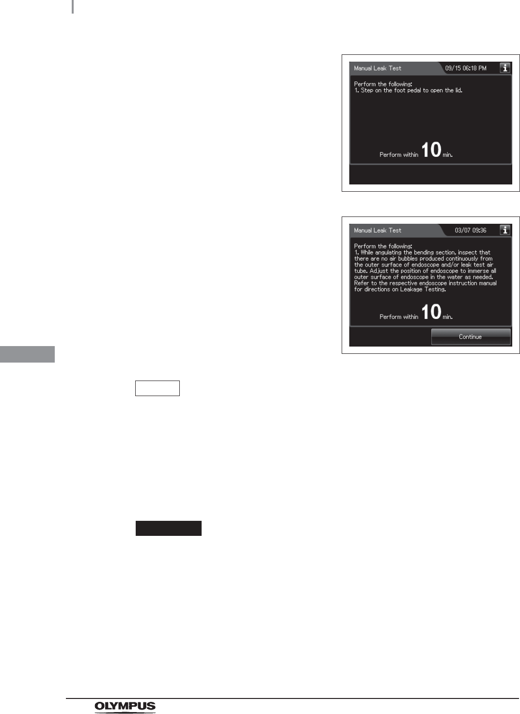
16 Ensure that the water supply is stopped and
then step on the foot pedal to open the lid.
When the lid is opened, the touch screen
displays the following screen. Perform from
Step 16 to Step 19 within 10 minutes after
opening the lid.
Figure 7.130
NOTE
If the lid is not opened within 10 minutes, the fluid in the reprocessing basin is
drained automatically and the manual leak test stops. The touch screen will then
display the error code [E092].
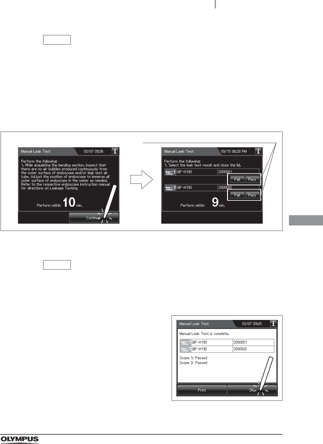
17 Check that there are not any bubbles produced continuously from the outer surface of
the endoscope and/or leak test air tube while angulating the bending section of the
endoscope. Check for leaks at least for 30 seconds.
CAUTION
• When angulating the endoscope’s bending section, do not to let the bending
section touch the reprocessing basin or retaining rack as this could damage the
endoscope. After bending, straighten the bending section and place it properly on
the retaining rack.
• During the manual leak test, be sure to angulate the bending section. Otherwise, it
would be impossible to find abnormalities in the endoscopes.
7.11 Manual leak test
309
OER-Elite OPERATION MANUAL
Ch.7
NOTE
• Adjust the position of endoscope to immerse all outer surface of endoscope in the
water as needed.
• If you set two endoscopes in the basin, it may be difficult to sufficiently immerse
endoscopes to inspect bubbles. In this case, perform the leakage test for each
endoscope separately.
18 Press the “Continue” button, and then input each manual leak test result on the touch
screen.
Figure 7.131
19 Close the lid by pushing until it clicks. The water starts to be drained.
NOTE
Even if the process is not completed by closing the lid, the water is drained
automatically 10 minutes after the water supply stopped. The touch screen will
then display error code [E092].
20 When draining has completed, the reprocessor
generates three buzzer beeps and the touch
screen shows the following screen. Press the
“OK” button to finish.
Figure 7.132
Selection of leak test Result for each endoscope
310
7.12 Auto leak test
OER-Elite OPERATION MANUAL
Ch.7
WARNING
When reprocessing the endoscopes after the manual leak test, be sure to
straighten their bending sections. Otherwise, the reprocessing may become
insufficient.
NOTE
• When the MAJ-1937 printer included in the optional MAJ-2144 printer set is
connected and the auto print setting is activated, the result of manual leak test is
printed automatically. For the setting changes of the auto print setting, refer to
Section 4.17, “Print option”.
• To print the manual leak test result without using the auto print setting, press the
“Print” button.
This function is used to perform auto leak test independently. Auto leak test is not available with certain
endoscopes. For detail unavailable of Auto leak test, refer to “Unavailable endoscope with the
functions of the OER-Elite” in “List of compatible Endoscopes/Connecting Tubes <OER-Elite>”.
A scope ID has to be input by an RFID. If a scope ID is input by using the scope ID master card, input
by the software keyboard or input by recalling the pre-registered ID, the auto leak test is not available.
CAUTION
• The leak test air tube may easily disconnect spontaneously if it is connected
insufficiently or, particularly if the lock lever is degraded. If the leak test air tube is
bent, sufficient air supply will not be possible. In both cases, the leak test of
endoscopes will be erroneous.
• Ensure that each leak test air tube is free of irregularity such as a crack, fissure,
scratch, or contamination. If an abnormal leak test air tube is used, the endoscope
may fail or the leak test will be erroneous.
• Before connecting a leak test air tube, ensure that the inner side of the tube, the
venting connector of the endoscope and the leak test connector of the reprocessor
are not wet. Otherwise, water penetrating inside the endoscope may cause a
failure of the endoscope.
• Be sure to connect the leak test air tubes securely. If the connection is insufficient,
the leak test may be abnormal because the inside of the endoscope cannot be
pressurized.
7.12 Auto leak test
7.12 Auto leak test
311
OER-Elite OPERATION MANUAL
Ch.7
CAUTION
• If an irregularity is found with a leak test air tube, replace it with a new tube and
retry the leak test.
• When a leak test air tube is not to be used, disconnect it from the connector and be
sure to remove it from the reprocessing basin. If reprocessing is performed without
removing it, the leak test may be erroneous.
• When the auto leak test gives a “Leaked” judgment to an endoscope do not
execute reprocessing program [1] to [4] on the endoscope. Otherwise, water may
penetrate inside the endoscope. The endoscope should be subjected to the leaking
scope decontamination and then serviced. For details on the leaking scope
decontamination, refer to Section 7.15, “Leaking scope decontamination”.
• The leak test result may become “Leaked” depending on the temperature of the
endoscope. To perform auto leak test with the ultrasonic endoscope, wait for more
than 30 minutes. To perform it with the other type of endoscope, wait for more than
15 minutes. Then, re-execute the auto leak test. If the result is “Leaked” again, the
scope should be subjected to the leaking scope decontamination and then
serviced. For details on the leaking scope decontamination, refer to Section 7.15,
“Leaking scope decontamination”.
NOTE
• The covering of the bending section of the endoscope may dilate slightly during the
leak test. This is not malfunction.
• The auto leak test may sometimes be incapable of detecting a very small hole.
312
7.12 Auto leak test
OER-Elite OPERATION MANUAL
Ch.7
Workflow of auto leak test
1Input scope ID of first endoscope.
on page 313
2
Loading of first endoscope in reprocessing basin and attaching
the leak test air tube.
on page 314
3Input scope ID of second endoscope.
on page 315
4
Loading of second endoscope in reprocessing basin and
attaching the leak test air tube.
on page 315
5Performing auto leak test.
on page 316
6Print format.
on page 316
7.12 Auto leak test
313
OER-Elite OPERATION MANUAL
Ch.7
Performing auto leak test
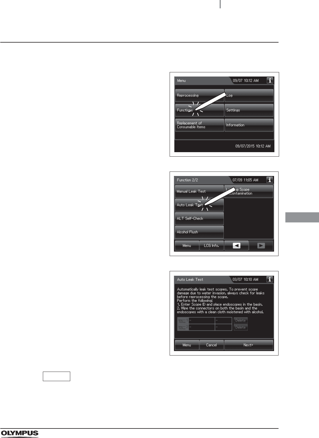
1Step on the foot pedal to open the lid.
2Press the “Functions” button on the Menu
Screen.
Figure 7.133
3Press the “Auto Leak Test” button on the 2nd
page of the Functions menu.
Figure 7.134
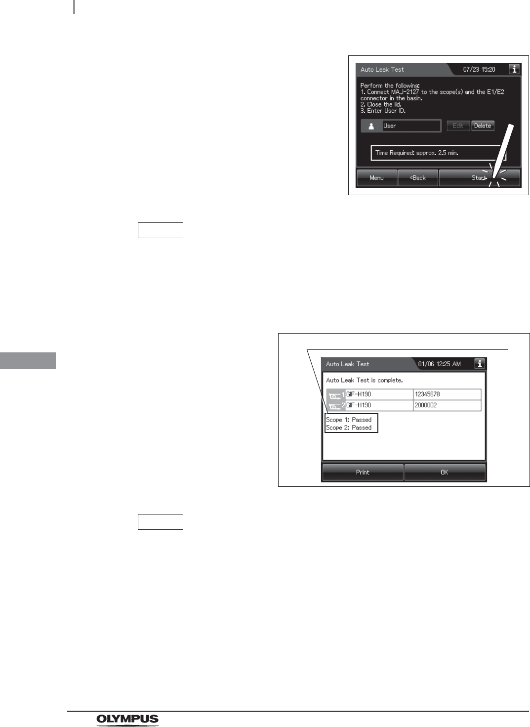
4Enter scope ID by RFID.
Figure 7.135
NOTE
To perform auto leak test, scope ID entry is allowed only by RFID. Other ID entry
method cannot be performed.
314
7.12 Auto leak test
OER-Elite OPERATION MANUAL
Ch.7
5Place the endoscope carefully, checking the following:
The distal end of the insertion tube is straight.
The distal end of the insertion tube is not on or beneath another object.
The leak test air tube is not twisted.
The leak test air tube is not contacting the lid.
6Wipe the venting connector of the endoscope or that of the waterproof cap with a
clean cloth immersed in 70% ethyl alcohol or 70% isopropyl alcohol.
Figure 7.136
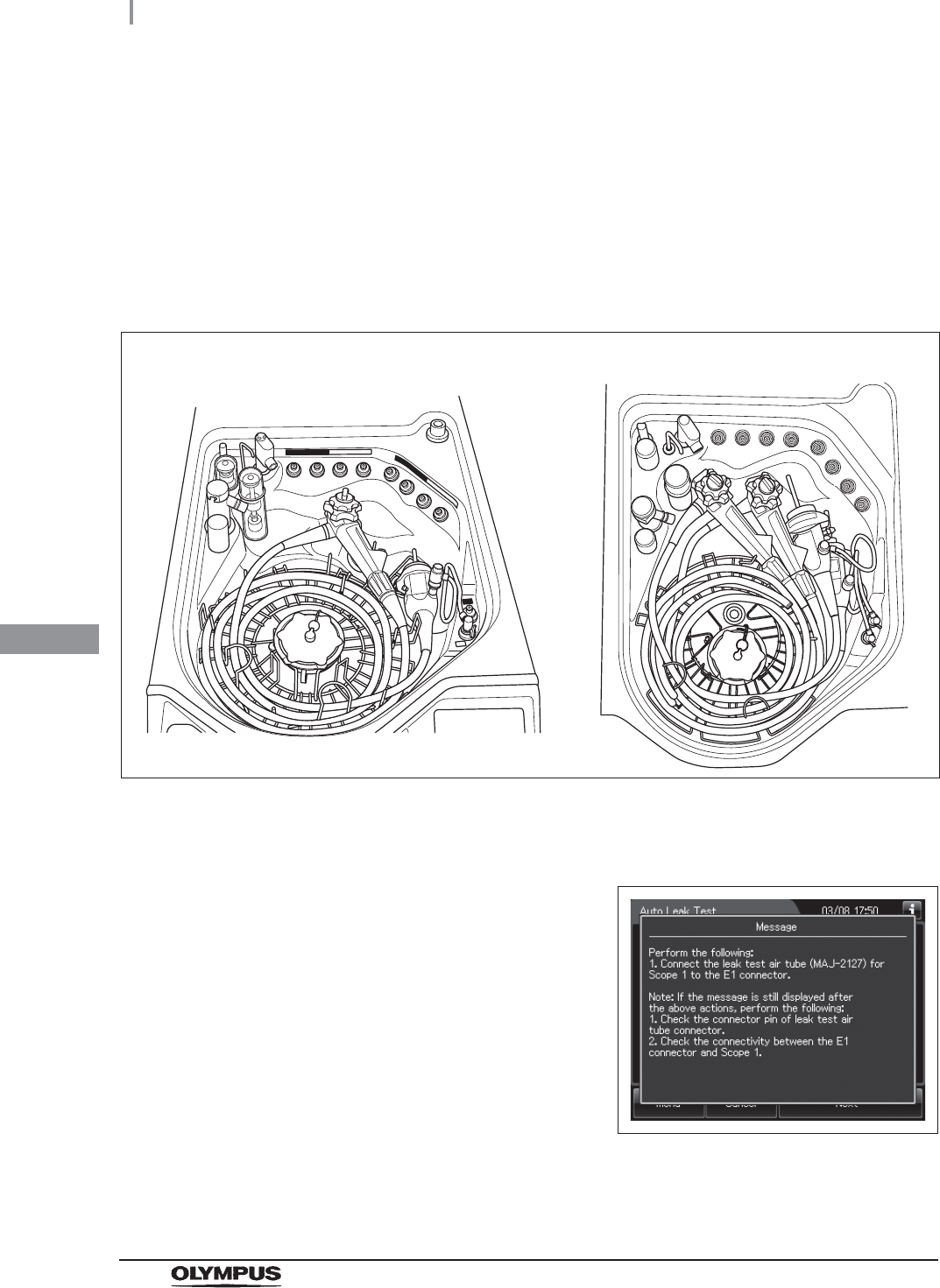
7If the leak test connector E1/E2 in the reprocessing basin is wet, wipe the entire
connector with a clean cloth.
8Entry the scope ID of the first endoscope, then
the message is displayed.
Figure 7.137
When reprocessing one endoscope When reprocessing two endoscope
7.12 Auto leak test
315
OER-Elite OPERATION MANUAL
Ch.7
9Connect the MAJ-2127 leak test air tubes to the
venting connector or the water resistant cap of
the first endoscope and leak test connector E1
in the reprocessing basin. When placing the
second endoscope, entry the scope ID of the
second endoscope, then connect the
MAJ-2127 leak test air tubes to the second
endoscope and leak test connector E2 in the
reprocessing basin.
Figure 7.138
CAUTION
Connect the first endoscope to the leak test connector E1 in the reprocessing
basin and the second endoscope to the leak test connector E2. If the endoscopes
are connected improperly, reconnect them by following the instructions displayed
on the touch screen. If the Auto leak Test is performed with wrong connections, the
leak test may be incorrect.
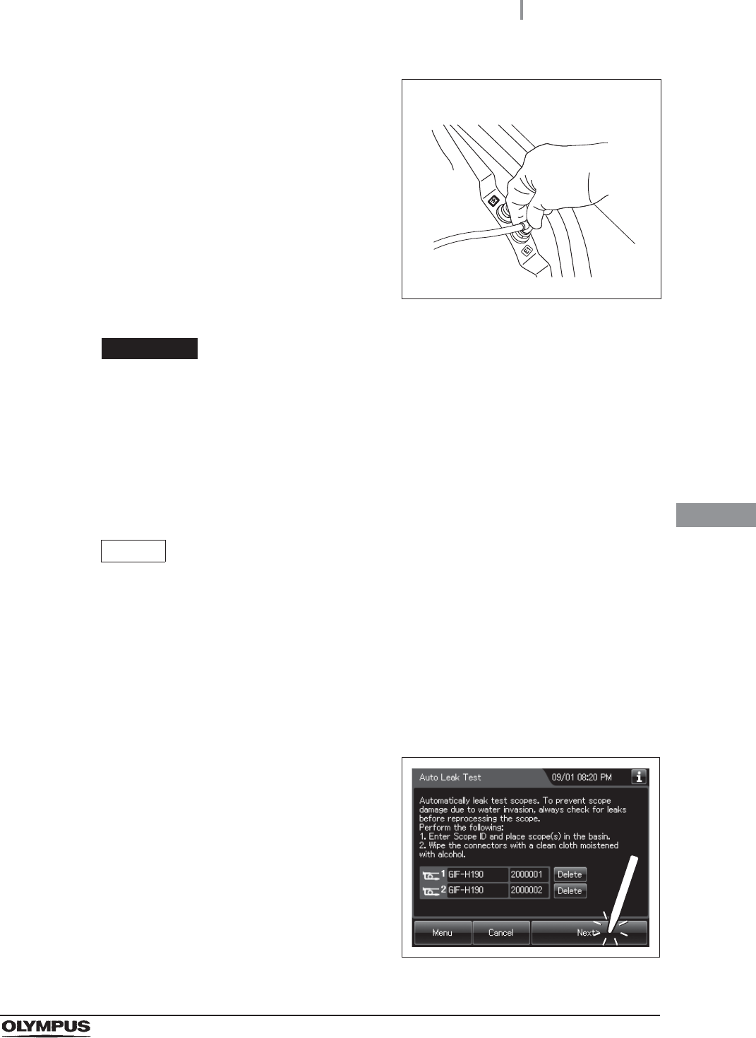
10 Place the second endoscope, same as from Step 2 through 9 of the first endoscope.
NOTE
• If the first endoscope is connected to connector E2 by mistake, the notification of
erroneous connection of the leak test air tube is displayed. Correct this by following
the instructions displayed on the touch screen.
• If the message is still displayed after connecting the MAJ-2127 leak test air tubes,
check the connector pin of leak test air tube connect and the connectivity between
the E1 connector and the first endoscope. If any irregularity is not found, contact
OLYMPUS.
11 Press the “Next” button.
Figure 7.139
First endoscope
316
7.12 Auto leak test
OER-Elite OPERATION MANUAL
Ch.7
12 Follow the guide displayed on the screen until
process starts. Enter user ID. For detailed
procedure, refer to Section 3.6, “Entering ID” (If
applicable).
Figure 7.140
NOTE
The user ID input can be omitted according to the user ID input setting. For details,
refer to Section 4.5, “User ID Setting”.
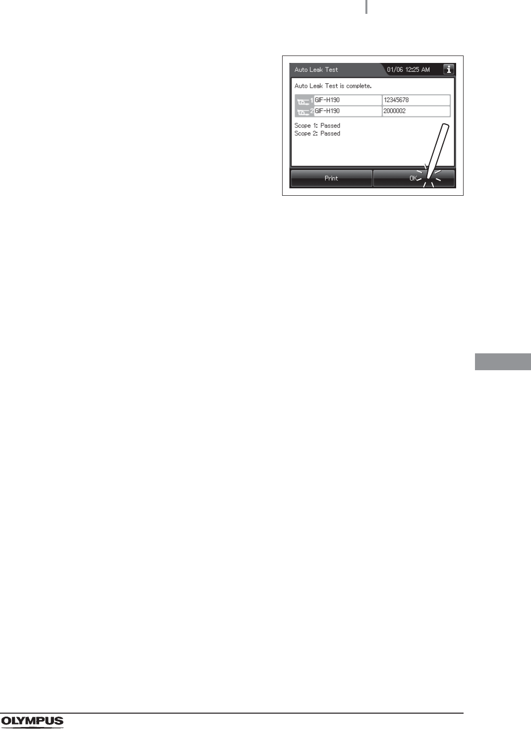
13 When the auto leak test process completes, the reprocessor generates a buzzer beep
and shows the following screen on the touch screen.
Figure 7.141
NOTE
• When the MAJ-1937 printer included in the optional MAJ-2144 printer set is
connected and the auto print setting is activated, the results of auto leak test are
printed automatically. For the setting changes of the auto print setting, refer to
Section 4.17, “Print option”.
• To print the auto leak test results without using the auto print setting, press the
“Print” button.
• If any leak were detected, refer to “When any leaks are detected” on page 617.
Results of auto leak test of each endoscope
7.12 Auto leak test
317
OER-Elite OPERATION MANUAL
Ch.7
14 Press the “OK” button to finish.
Figure 7.142
318
7.12 Auto leak test
OER-Elite OPERATION MANUAL
Ch.7
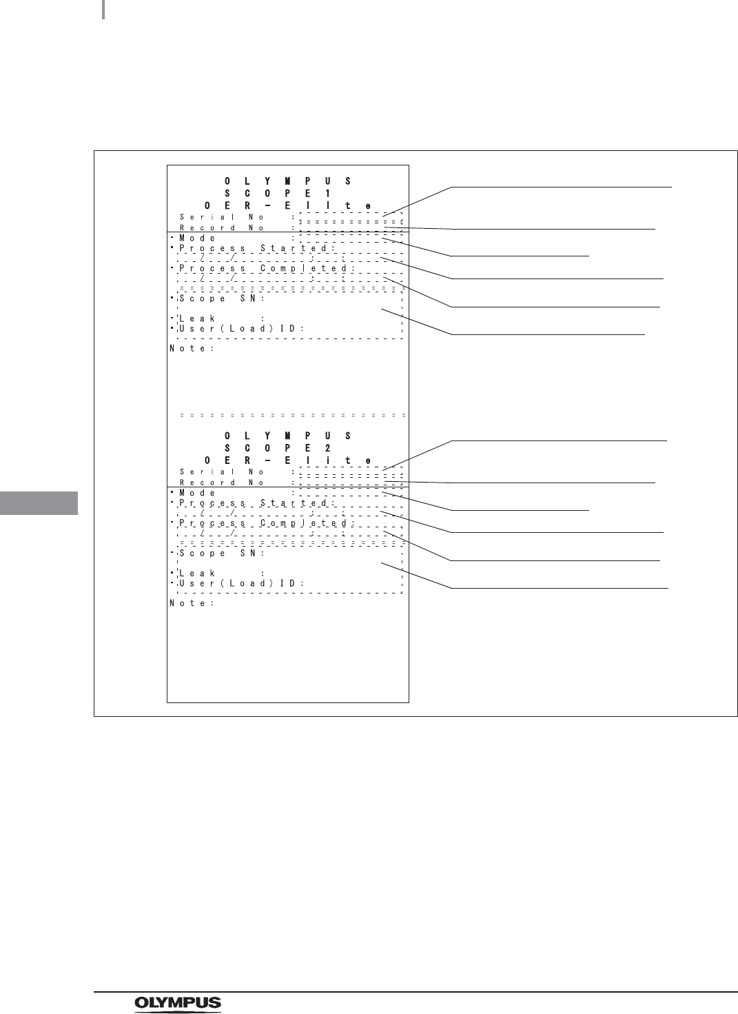
Print format
(a) When the print format setting is “Separated”:
Figure 7.143
Serial number of this reprocessor
Date and time of start of process
Date and time of end of process
Information of first endoscope
Number given to each record in
the order of occurrence
Type of the leak test
Serial number of this reprocessor
Date and time of start of process
Date and time of end of process
Information of second endoscope
Number given to each record in
the order of occurrence
Type of the leak test
7.12 Auto leak test
319
OER-Elite OPERATION MANUAL
Ch.7
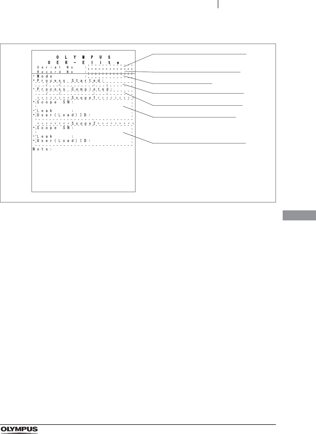
(b) When the print format setting is “Combine”:
Figure 7.144
Serial number of this reprocessor
Date and time of start of process
Date and time of end of process
Information of first endoscope
Number given to each record in
the order of occurrence
Type of the leak test
Information of second endoscope
320
7.12 Auto leak test
OER-Elite OPERATION MANUAL
Ch.7
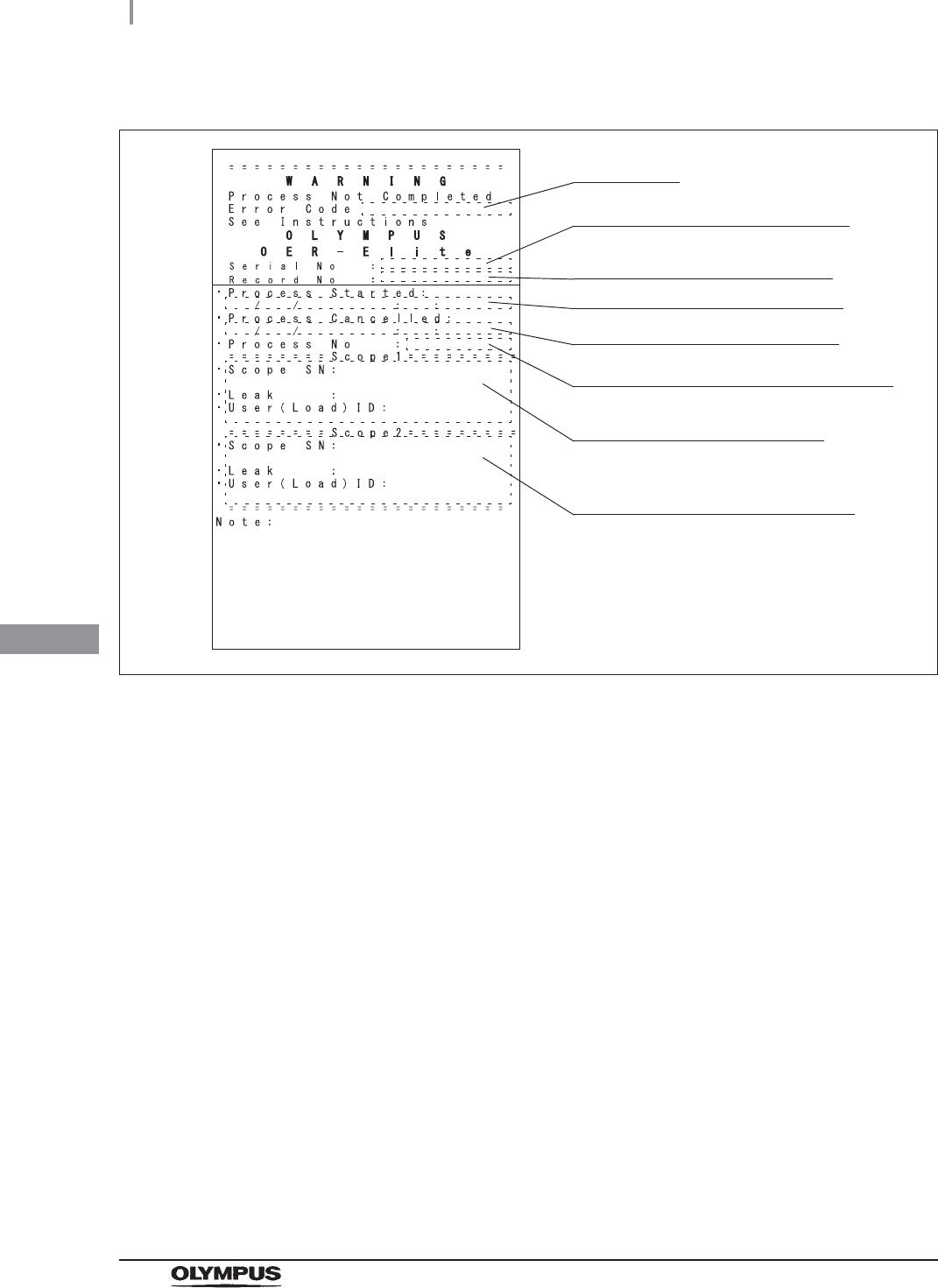
(c) When error occurs during auto leak test:
Figure 7.145
Serial number of this reprocessor
Date and time of start of process
Date and time of end of process
Process number of occurrence of error
Information of first endoscope
Error code
Number given to each record in
the order of occurrence
Information of second endoscope
7.13 Self-check of auto leak test
321
OER-Elite OPERATION MANUAL
Ch.7
This function is checked the operation of the auto leak test function.
The self-check of auto leak function is performed automatically during the load LCG process. However,
if the load LCG process stops and an error code ([E112], etc.) is generated, execute the Self-check of
auto leak test.
CAUTION
Do not connect any leak test air tubes to leak test connectors E1 or E2 on the
reprocessing basin. Otherwise, the self-check will not run properly and Auto Leak
Test function will not work properly.
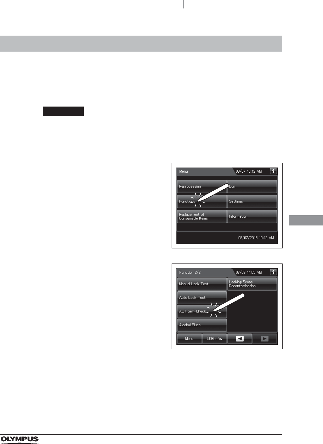
7.13 Self-check of auto leak test
1Press the “Functions” button on the Menu
screen.
Figure 7.146
2Press the “ALT Self-Check” button on the 2nd
page of the Function menu.
Figure 7.147
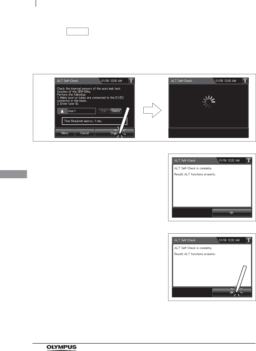
3Input the operator’s user ID. For the detailed procedure, refer to Section 3.6, “Entering
ID” (If applicable).
322
7.13 Self-check of auto leak test
OER-Elite OPERATION MANUAL
Ch.7
NOTE
The user ID input can be omitted according to the user ID input setting. For details,
refer to Section 4.5, “User ID Setting”.
4Press the “Start” button. The process starts.
Figure 7.148
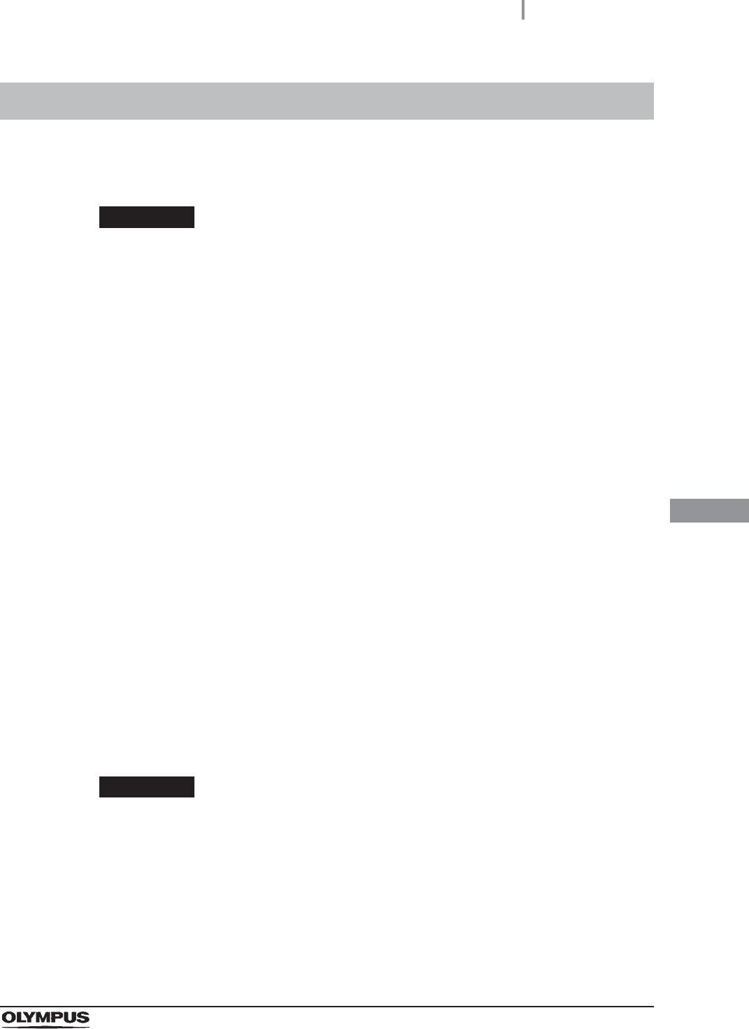
5When the process completes, the reprocessor
generates a buzzer beep and displays the
result.
Figure 7.149
6Press the “OK” button to finish.
Figure 7.150
7.14 Alcohol flush
323
OER-Elite OPERATION MANUAL
Ch.7
This process automates the flushing of the endoscope channels with alcohol followed by air to help dry
the channels.
WARNING
• When using the disinfectant solution and alcohol, Olympus recommends the use of
gas filters and running this reprocessor in well-ventilated areas.
Wear a face mask, gloves, and protective clothes to minimize aspiration and
skin contact.
Wear goggles for eye protection.
Refer to the following association’s guidelines related to ventilation:
If the person operating the reprocessor exhibits an allergic reaction or symptoms,
no matter how slight, they should discontinue the task they are performing and
vacate the room.
• When the alcohol flush process is stopped due to an reprocessor error, do not use
the endoscope and restart the alcohol flush process from the beginning. Otherwise,
alcohol may remain in the endoscope channel and pose a risk to patient safety.
CAUTION
Do not perform alcohol flush without connecting the connecting tubes. Otherwise,
excessive pressure on the pipes in the reprocessor may damage it.
7.14 Alcohol flush
SGNA (Society of Gastroenterology Nurses and Associates)
ASGE (American Society of Gastroenterological Endoscopy)
APIC (Association for Professionals of Infection Control and Epidemiology)
AORN (Association of Preoperative Registered Nurses)
ASTM (American Society for Testing and Materials)
OSHA (Occupational Safety and Health Administration)
ACGIH (American Conference of Governmental Industrial Hygienists)
NIOSH (National Institute for Occupational Safety and Health)
AIA (American Institute of Architects)
324
7.14 Alcohol flush
OER-Elite OPERATION MANUAL
Ch.7
1Check the alcohol tank check window on the reprocessor’s detergent/alcohol drawer
to confirm that the surface of alcohol is visible. If the alcohol has reduced, add more
alcohol as described in Section 5.9, “Inspecting and replenishing alcohol”.
NOTE
Alcohol flush includes the water feed and drain operations. These operations are
intended to drain alcohol while diluting it.
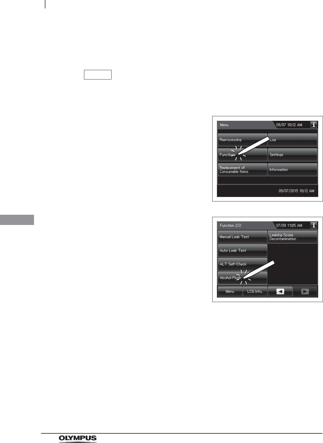
2Press the “Functions” button on the Menu
screen.
Figure 7.151
3Press the “Alcohol Flush” button on the 2nd
page of the Function menu.
Figure 7.152
4Follow the guide displayed on the touch screen. Firstly, step on the foot pedal to open
the lid.
5Place the endoscope(s) in the reprocessing basin.
6Connect connecting tubes to the endoscope(s) and the connectors on the
reprocessing basin according to the “List of Compatible Endoscopes/Connecting
Tubes <OER-Elite>”.
7Enter the user ID. (If applicable)
7.14 Alcohol flush
325
OER-Elite OPERATION MANUAL
Ch.7
NOTE
The user ID input can be omitted according to the user ID input setting. For details,
refer to Section 4.5, “User ID Setting”.
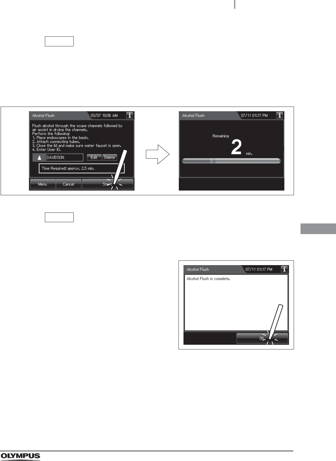
8Press the “Start” button. Alcohol flush starts and the touch screen displays the
remaining time, which will count down every minute.
Figure 7.153
NOTE
Water supply and draining are performed in this process. These operations are
intended to dilute the alcohol and drain the dilution.
9When the alcohol flush process completes, the
reprocessor generates a buzzer beep and
shows the following screen on the touch
screen. Press the “OK” button to finish.
Figure 7.154
326
7.15 Leaking scope decontamination
OER-Elite OPERATION MANUAL
Ch.7
If water leak of endoscope is detected in a leak test before manual cleaning or an auto leak test before
reprocessing, apply leaking scope decontamination for the endoscope before sending it for servicing
center. By using this function the endoscope can be immersed in the disinfectant solution while
preventing from influx of disinfectant solution into the internal of the endoscope.
In case error code [E115] is displayed during the auto leak test process, perform the manual leak test
and confirm area(s) of the leaking point(s). If a leaking point is found, thoroughly dry the identified
location of the leak on the outer area of the endoscope using alcohol and a clean lint-free cloth.
Carefully apply a piece of electrical tape or other waterproof tape over the location of the leak prior to
immersing the endoscope in detergent solution. Wrapping the tape too tightly may result in damage to
the endoscope. Then perform the Leaking scope decontamination with the endoscope. If error code
[E115] is generated again in Leaking scope decontamination, the leaking point cannot be stopped by
taping, or a leaking point is not found, do not perform this process but contact Olympus. For details,
refer to “Manual decontamination for leaking endoscope” on page 619.
WARNING
• The leaking scope decontamination process is intended to decontaminate a leaking
endoscope before sending it to a servicing center. It does not guarantee the
reprocessing of the endoscope and its accessories after this process. After
completing this process, do not use the endoscope and its accessories in
examination but send it to a servicing center.
• Do not subject an endoscope without leak (correctly functioning endoscope) in this
process.
• Do not perform the Leaking scope decontamination process with auxiliary water
tubes. This process is not capable of high-level disinfection of the auxiliary water
tubes. Even when the auxiliary water tube cleaning setting is activated, do not use
the MAJ-2138. Instead, be sure to use the provided MAJ-2113. Otherwise, the
reprocessing of the auxiliary water tubes may be insufficient.
• When handling the disinfectant solution, wear personal protective equipment to
prevent any disinfectant solution from getting on your skin and eyes or being
inhaled. Avoid direct physical contact and inhalation of vapors. If any disinfectant
solution gets in your eyes, immediately rinse with a large amount of fresh water and
then consult a medical specialist. Wear personal protective equipment, such as
eyewear, face mask, moisture-resistant clothing, and chemical-resistant gloves that
fit properly and are long enough so that your skin and eyes is not exposed. All
personal protective equipment should be inspected before use and replaced
periodically.
7.15 Leaking scope decontamination

7.15 Leaking scope decontamination
327
OER-Elite OPERATION MANUAL
Ch.7
WARNING
• Before proceeding to the leaking scope decontamination, always be sure to check
using a test strip that the concentration of the disinfectant solution is no less than
the minimum recommended concentration. If this check is not performed,
decontamination may be insufficient. The disinfectant solution should be replaced
when the concentration falls below the minimum recommended concentration or
the shelf life of the disinfectant solution has expired.
• Disinfectant vapor may still be in the reprocessing basin immediately after the lid is
opened. Wear appropriate personal protective gear to prevent excessive inhalation
of the vapor.
• Before disconnecting a connecting tube, visually confirm that there are no
irregularities such as kinking, accidental detachment or use of wrong connecting
tube and confirm that each connecting tube is firmly attached. If any irregularity is
observed, it must be corrected and the endoscope must be reprocessed again.
Otherwise, the reprocessing may insufficient.
• If any irregularity is found with the connection of the connecting tubes, connect
them correctly and retry leaking scope decontamination. Otherwise,
decontamination may be insufficient.
• Be sure to wear sterilized gloves when taking out the decontaminated endoscope.
Otherwise, attaching of dirt on the hand on the endoscope may cause infection.
• This process does not guarantee reprocessing of the endoscope. Pay attention to
in handling the endoscope by wearing protective gear, etc.
CAUTION
• Only one endoscope can be installed in the leaking scope decontamination.
Otherwise, more water may leak into the endoscope during leaking scope
decontamination.
• Always install only one endoscope. If two scopes are installed, water may
penetrate inside them.
NOTE
If water leak is detected in the auto leak test performed according to the setting for
the operation after reprocessing, send the endoscope to repair without performing
this process.
328
7.15 Leaking scope decontamination
OER-Elite OPERATION MANUAL
Ch.7
Workflow of leaking scope decontamination
Required items
Table 7.6
NOTE
• For the usable test strips, refer to Section 2.8, “Consumable accessories
(Optional)”.
• For connecting tubes required for leaking scope decontamintation, refer to the
Connection Guide screen or “List of Compatible Endoscopes/Connecting Tubes
<OER-Elite>”.
1Performing leaking scope decontamination
on page 329
2Print format
on page 337
Check Required Item
FDA-cleared chemical indicator (test strip)
Connector jig
Connecting tubes
Leak test air tube
7.15 Leaking scope decontamination
329
OER-Elite OPERATION MANUAL
Ch.7
Performing leaking scope decontamination
WARNING
Always use the connecting tube MAJ-2113 for endoscope with the auxiliary water
channel and do not use connecting tube MAJ-2138 in this process. Otherwise,
insufficient fluid supply to them may make their decontamination insufficient.
CAUTION
Before performing the leak scope decontamination, make sure that the leak test air
tubes and the connectors of reprocessing basin are free of irregularities such as
cracks, breaks, and so on. Otherwise, the endoscopes may malfunction.
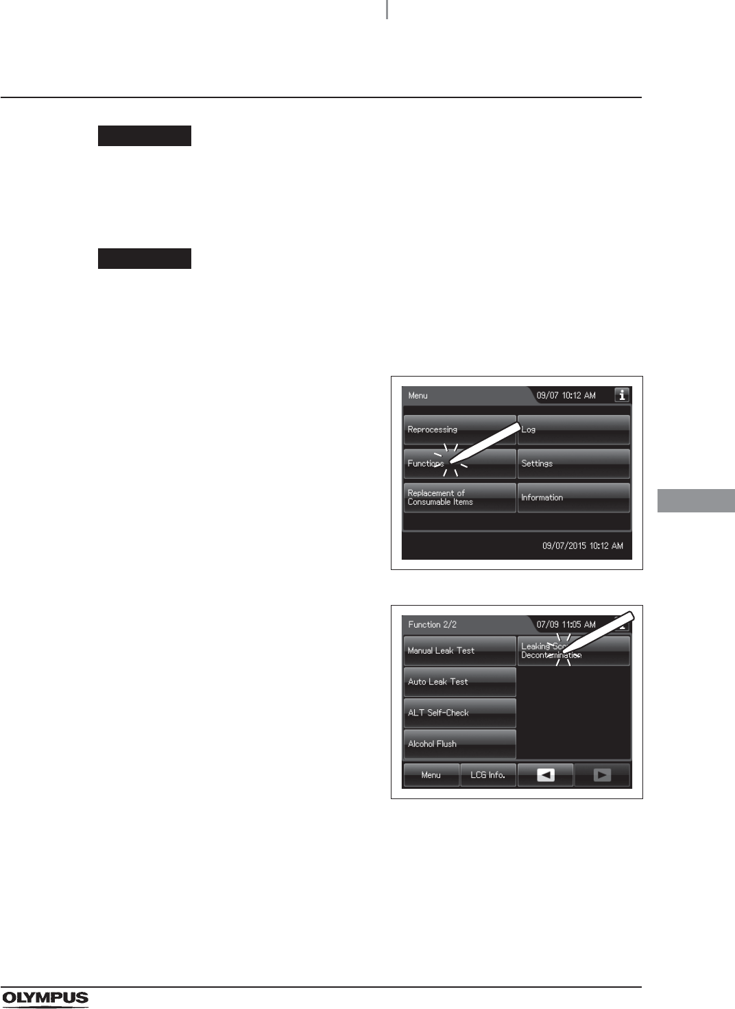
1Press the “Functions” button on the Menu
screen.
Figure 7.155
2Press the “Leaking Scope Decontamination”
button on the 2nd page of the functions menu
screen.
Figure 7.156
330
7.15 Leaking scope decontamination
OER-Elite OPERATION MANUAL
Ch.7
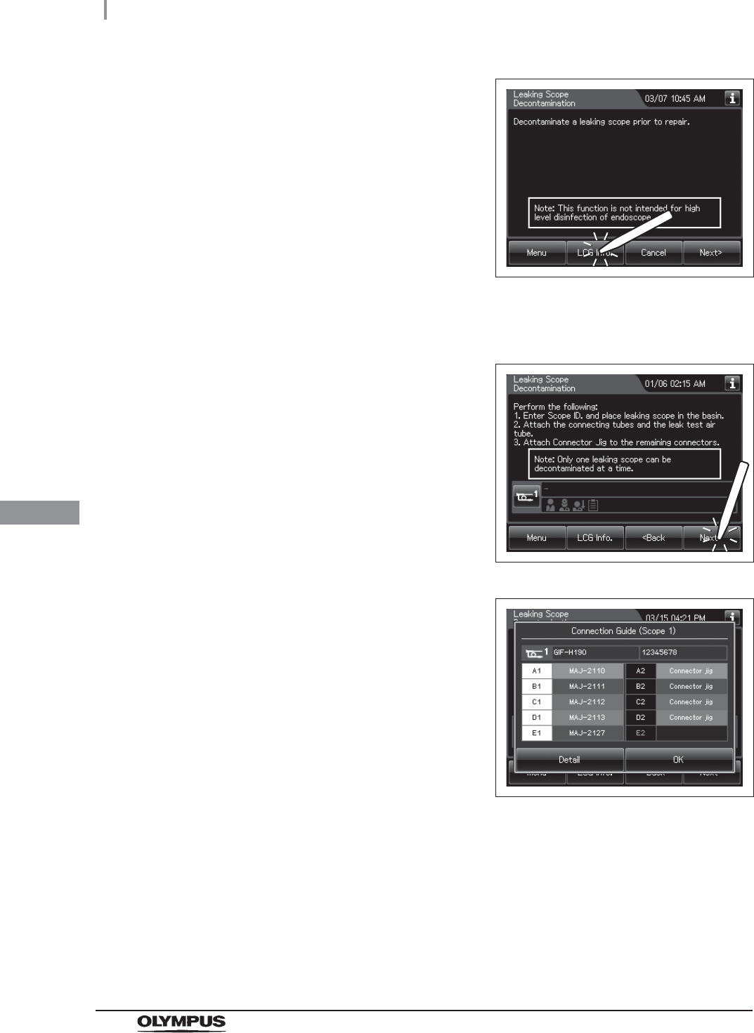
3Press the “LCG Info.” button to display the LCG
Info screen.
Figure 7.157
4Check the MRC and input the result by following the instructions given in Section 3.7,
“Checking the MRC level and entering the check result”.
5Press the “Next” button repeatedly until the
touch screen display changes as shown below.
Figure 7.158
6Input the scope ID of the leaking endoscope.
For the detailed procedures, refer to
Section 3.6, “Entering ID” (If applicable).
Figure 7.159
7Place the leaking endoscope in the reprocessing basin. For the detailed procedures,
refer to “Loading of second endoscopes in the reprocessing basin” on page 197.
8Connect the connecting tubes by following the instructions given on the connection
guide screen. For the connecting tube connection method, refer to “Loading of
second endoscopes in the reprocessing basin” on page 197.
7.15 Leaking scope decontamination
331
OER-Elite OPERATION MANUAL
Ch.7
CAUTION
If the scope ID is input by the software keyboard or input by recalling the
pre-registered ID, confirm the connecting tubes to be used in “List of Compatible
Endoscopes/Connecting Tubes <OER-Elite>” and connect all of them. Otherwise,
disinfectant solution cannot be fed into the scope channels.
9Wipe the venting connector of the endoscope or that of the waterproof cap with a
clean moistened with 70% ethyl alcohol or 70% isoproply alcohol.
10 If the leak test connector E1 in the reprocessing basin is wet, wipe the entire
connector with a clean cloth.
11 Connect the MAJ-2127 leak test air tubes to the venting connector or the water
resistant cap of the first endoscope and leak test connector E1 in the reprocessing
basin.
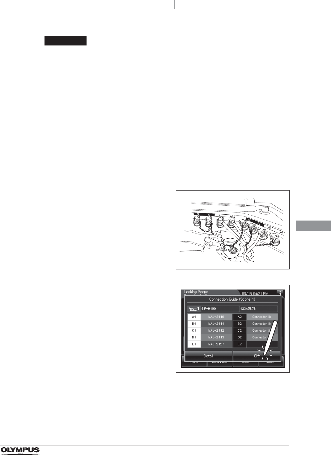
12 Connect the connector jig to remaining connectors in the reprocessing basin.
13 Place unused connectors of connector jig as
shown in the figure.
Figure 7.160
14 Press the “OK” button on the Connection Guide
screen.
Figure 7.161
332
7.15 Leaking scope decontamination
OER-Elite OPERATION MANUAL
Ch.7
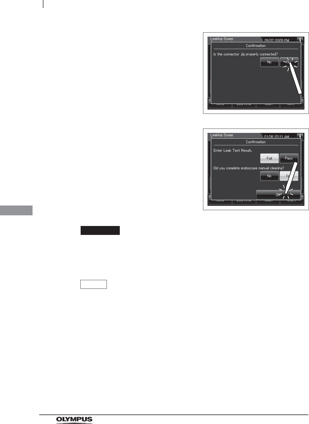
15 Check that connector jig is connected to
remaining connectors in the reprocessing basin
and then press the “Yes” button.
Figure 7.162
16 Select whether or not the endoscope has been
cleaned manually and whether or not leak was
found, and press the “OK” button.
Figure 7.163
CAUTION
Connect the connector jig to all of the reprocessing basin’s connectors to which the
connecting tubes are not connected except for connector E2. If the connector jig
are not connected or connected improperly, water may leak into the endoscope.
NOTE
The input of the result of manual cleaning and leak test can be disabled by
changing a setting. For details, refer to Section 4.4, “Manual cleaning and leak test
setting”.
17 Check the connection between endoscope and the OER-Elite.
The connecting tubes and leak test air tube are not kinked and bent.
The unnecessary connecting tubes are not connected to the OER-Elite except for the
connector jig.
7.15 Leaking scope decontamination
333
OER-Elite OPERATION MANUAL
Ch.7
18 When the touch screen display changes as
shown below, input the user ID (load),
physician ID and patient ID and procedure ID.
For the ID input procedure, refer to Section 3.6,
“Entering ID” (If applicable).
Figure 7.164
NOTE
• The user ID (load) input can be omitted by changing the user ID setting. For the
user ID setting, refer to Section 4.5, “User ID Setting”.
• The physician ID input can be omitted by changing the physician ID setting. For the
physician ID setting, refer to Section 4.6, “Physician ID setting”.
• The patient ID input can be omitted by changing the patient ID setting. For the
patient ID setting, refer to Section 4.7, “Patient ID setting”.
• The procedure ID input can be omitted by changing the procedure ID setting. For
the procedure ID setting, refer to Section 4.9, “Procedure ID setting”.
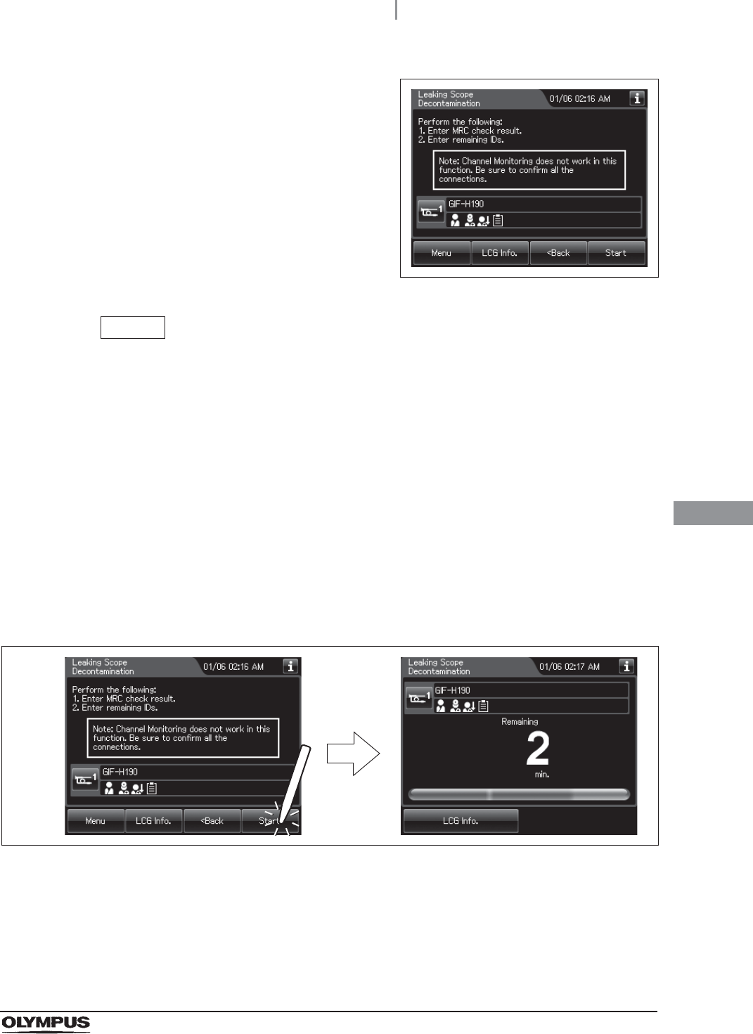
19 Close the lid by pushing until it clicks.
20 Press the “Start” button. The process starts and the touch screen displays the
remaining time, which will count down every minute.
Figure 7.165
334
7.15 Leaking scope decontamination
OER-Elite OPERATION MANUAL
Ch.7
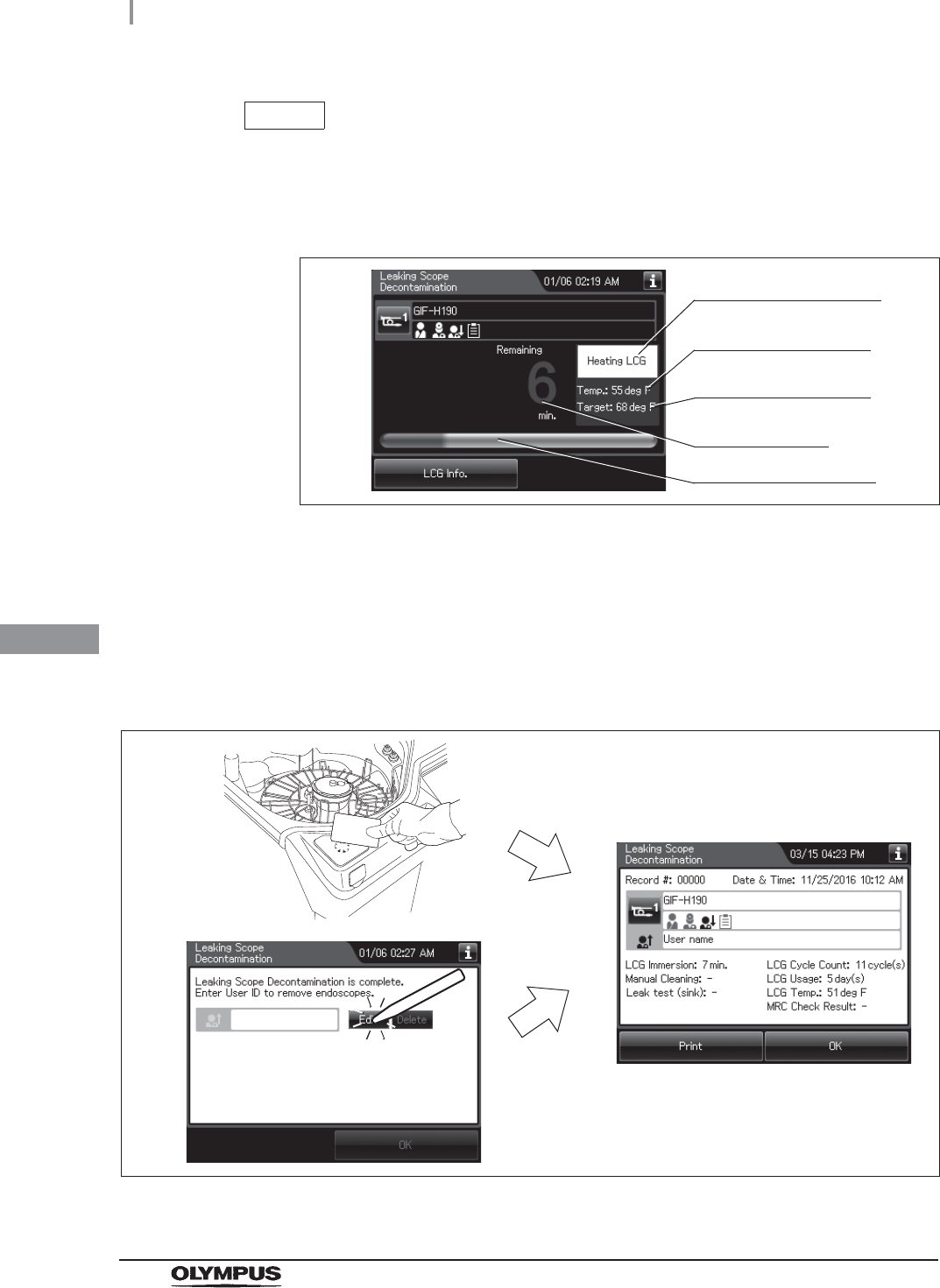
NOTE
When the disinfectant solution temperature is below 20°C (68°F), it is heated to
20°C (68°F). During heating, the remaining time countdown and progress bar on
the touch screen stops and turns gray. The remaining time countdown restarts after
completion of heating.
Figure 7.166
21 When the user ID (remove) setting for end of reprocessing is activated, enter the
operator’s user ID as instructed in Section 3.6, “Entering ID” (If applicable). When the
user ID (remove) is input from the RFID, the touch screen switches to the next screen.
When the input is performed manually or from the previous registration, press the
“OK” button to switch the screen.
Figure 7.167
Flashes during heating
Current temperature of
disinfectant solution
Target temperature of
disinfectant solution
Remaining time
Process progress bar
7.15 Leaking scope decontamination
335
OER-Elite OPERATION MANUAL
Ch.7
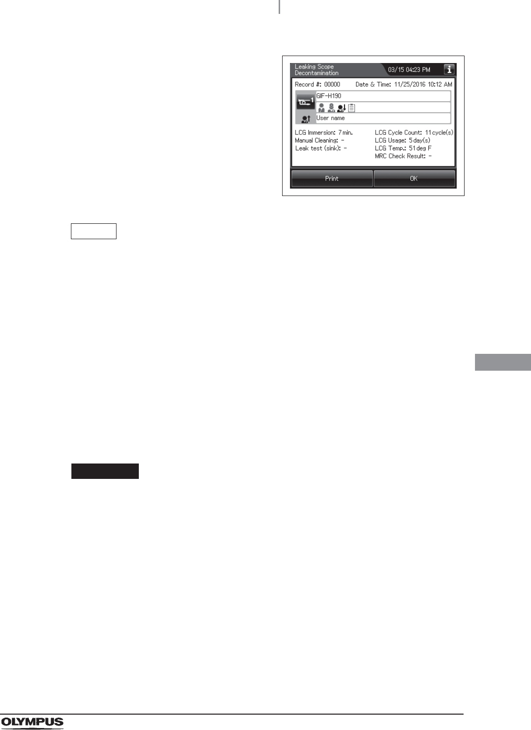
22 When this process completes, the reprocessor
generates three buzzer beeps and the touch
screen shows the following screen.
Figure 7.168
NOTE
• When the MAJ-1937 printer included in the optional MAJ-2144 printer set is
connected and the auto print setting is activated, the result of leaking scope
decontamination is printed automatically. For the setting changes of the auto print
setting, refer to Section 4.17, “Print option”.
• To print the leaking scope decontamination result without using the auto print
setting, press the “Print” button.
23 Press the foot switch to open the lid.
24 Check the connecting tubes and Leak test air tube status.
if the tubes are bent,
if they are connected securely to the connectors,
if they are free of abnormality such as a crack.
CAUTION
The endoscope may fail when the tube is used the next time.
25 Disconnect the connecting tubes and leak test air tube from the endoscope.
26 Take the endoscope out of the reprocessing basin. Wipe off any water using a piece
of clean gauze.
27 Take the connecting tubes, leak test air tube and connector jig out of the reprocessing
basin, wipe off any water using a piece of clean gauze, and store them in a clean
place.
336
7.15 Leaking scope decontamination
OER-Elite OPERATION MANUAL
Ch.7
NOTE
Be sure to have the decontaminated endoscope serviced.
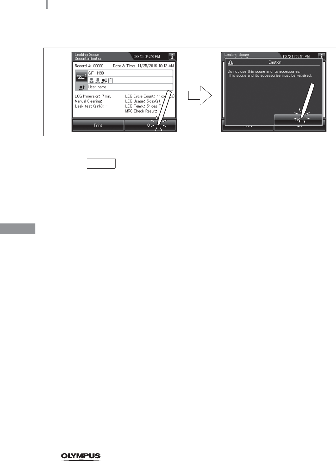
28 Press the “OK” button twice to finish.
Figure 7.169
7.15 Leaking scope decontamination
337
OER-Elite OPERATION MANUAL
Ch.7
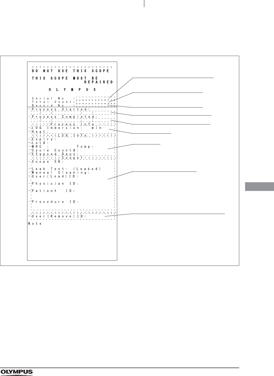
Print format
(a) Normal
Figure 7.170
Serial number of this reprocessor
Date and time of start of process
Date and time of end of process
Information of endoscope
User ID (remove) of the end of process
Total accumulated of
reprocessing process count
Number given to each record
in the order of occurrence
Setting details
LCG Info.
338
7.15 Leaking scope decontamination
OER-Elite OPERATION MANUAL
Ch.7
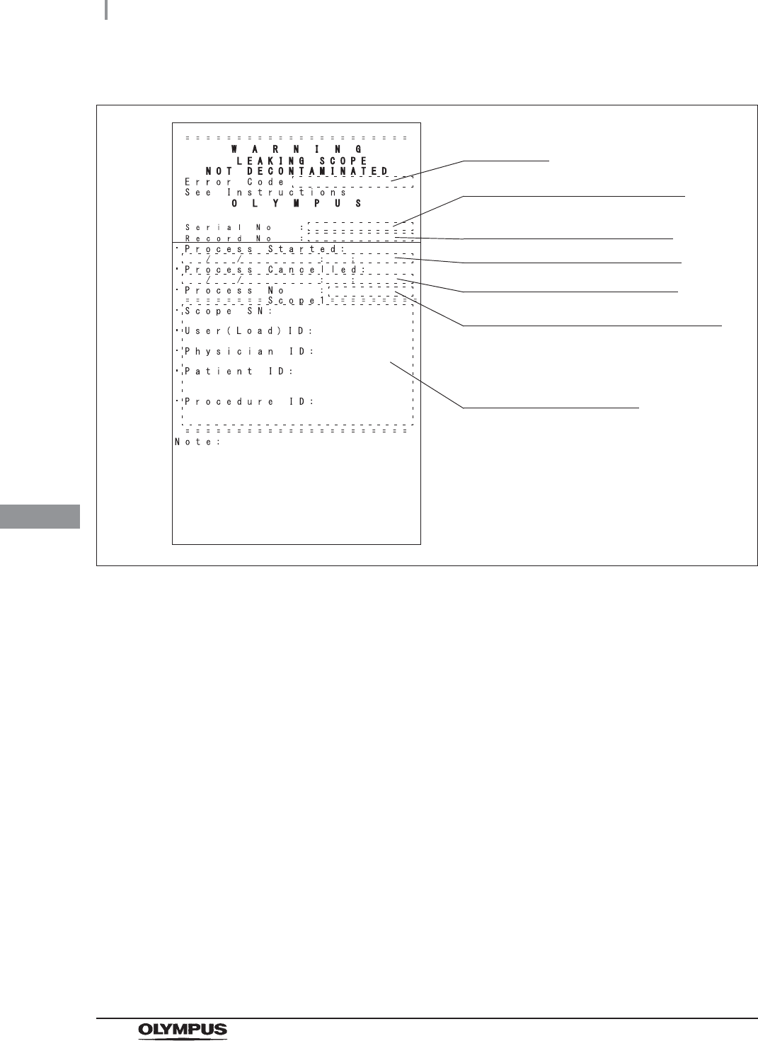
(b) Error
Figure 7.171
Serial number of this reprocessor
Date and time of start of process
Date and time of end of process
Process number of occurrence of error
Information of endoscope
Error code
Number given to each record in
the order of occurrence
8.1 Replacement of consumable items menu
339
OER-Elite OPERATION MANUAL
Ch.8
Chapter 8 Replacement of
Consumable Items
NOTE
There is no button for replenishing alcohol. For replenishing alcohol, refer to
Section 5.9, “Inspecting and replenishing alcohol”.
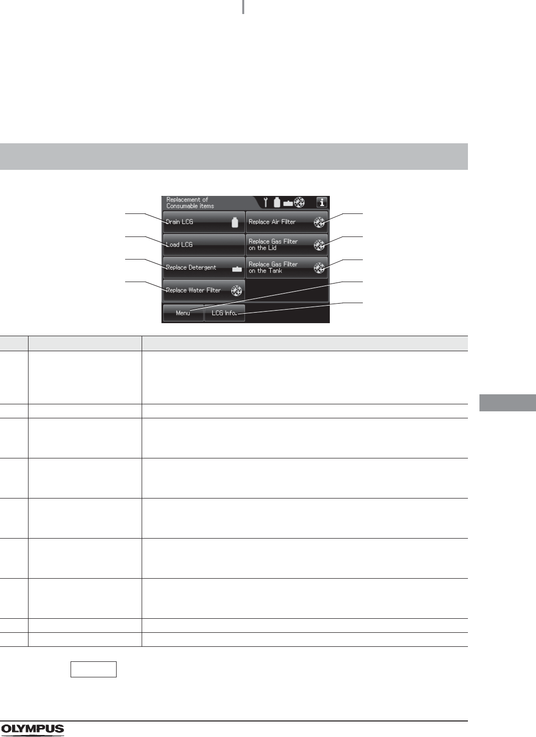
8.1 Replacement of consumable items menu
No. Button Description
1 Drain LCG button Press to drain the disinfectant solution in the disinfectant solution tank.
When the usage count setting of the disinfectant solution counter or the shelf life
of the disinfectant solution is reached, the disinfectant solution replacement
indicator appears in the button.
2 Load LCG button Press to prepare a new disinfectant solution.
3 Replace Detergent button Press to load the detergent tank.
When the usage count setting of the detergent counter or the shelf life of the
detergent is reached, the detergent replacement indicator appears in the button.
4 Replace Water Filter
button
Press to replace the water filter.
When the usage count setting of the water filter counter, the water filter
replacement indicator appears in the button.
5 Replace Air Filter button Press to replace the air filter.
When the usage count setting of the air filter counter, the air filter replacement
indicator appears in the button.
6 Replace Gas Filter on the
Lid button
Press to replace the gas filter on the lid.
When the usage count setting of the lid’s gas filter counter, the filter replacement
indicator appears in the button.
7 Replace the Gas Filter on
the Tank button
Press to replace the gas filter on the disinfectant solution tank.
When the usage count setting of the disinfectant solution tank’s gas filter counter,
the filter replacement indicator appears in the button.
8 Menu button Press to display the Menu screen.
9 LCG Info. button Press to display the LCG Info. screen.
1
2
3
4
5
6
7
8
9
340
8.2 Replacing the disinfectant solution
OER-Elite OPERATION MANUAL
Ch.8
When the disinfectant solution in the reprocessor is no longer effective, or beyond the specified use
life, drain the disinfectant solution completely and replace with fresh disinfectant solution. Expired
disinfectant solution should be treated as directed in the documents supplied with the disinfectant
solution.
WARNING
• Remove all endoscopes, valves, and connecting tubes from the reprocessing basin
before draining the disinfectant solution. Otherwise, the disinfectant solution cannot
be drained properly, it cannot be mixed sufficiently, and the endoscopes and valves
may be unable to be rinsed sufficiently.
• Before handling the disinfectant solution, read the cautions carefully and use it as
instructed. Be sure that you fully understand what measures need to be taken if you
get any disinfectant solution on your skin and eyes.
• Always use a disinfectant that has been validated by Olympus. High-level
disinfectants that are not validated by Olympus for use in the OER-Elite may be
unsafe and ineffective due to improper dilution, incorrect contact time and
temperature, excessive foaming, inadequate rinse, and therefore may compromise
patient safety. Use of a high-level disinfectant that has not been validated by
Olympus may also damage internal OER-Elite components (e.g., seals, valves,
etc.) and the endoscopes being reprocessed.
• When handling the disinfectant solution, wear appropriate personal protective
equipment to prevent direct contact with your skin and eyes or excessive inhalation
of the vapor. The disinfectant solution and its vapor may adversely affect the
human body. If you get disinfectant solution in your eyes, immediately rinse with a
large quantity of water and then call the doctor. Wear personal protective
equipment, such as eyewear, face mask, moisture-resistant clothing, and
chemical-resistant gloves that fit properly and are long enough so that your skin
and eyes is not exposed. All personal protective equipment should be inspected
before use and replaced periodically before it is damaged.
CAUTION
Expired disinfectant solution should be treated in accordance with the instructions
supplied with the disinfectant solution. It is recommended to treat the waste fluid
properly and to dispose of it according to local wastewater standards defined by
law, or temporarily collect and store the waste fluid and have it treated by a waste
disposal firm.
8.2 Replacing the disinfectant solution
8.2 Replacing the disinfectant solution
341
OER-Elite OPERATION MANUAL
Ch.8
NOTE
When the disinfectant solution counter setting and/or shelf life setting is activated,
the disinfectant solution replacement indicator can be displayed on the top right of
the touch screen and on the “Drain LCG” button on the Replacement of
Consumable Items menu when the counter setting value or shelf life setting value
is reached. For the disinfectant solution counter setting, refer to Section 4.12, “LCG
replacement indicator”. For the shelf life setting, refer to Section 4.13, “LCG lot
number and shelf-life management”.
Workflow of replacement the disinfectant solution
See the replacement of the disinfectant solution workflow below.
1
Drain the disinfectant solution.
• Draining through the disinfectant collection hoseon page 342
• Draining through the drain hoseon page 350
2Load the disinfectant solution.
on page 354
342
8.2 Replacing the disinfectant solution
OER-Elite OPERATION MANUAL
Ch.8
Draining the disinfectant solution
Table 8.1
Draining through the disinfectant collection hose
WARNING
• Do not push the disinfectant removal port when the rubber cap is not attached. To
do so may cause the disinfectant solution to flow out.
• To prevent peripheral device and areas near the reprocessor from being damaged
by leaking disinfectant solution, do not remove the rubber cap from the disinfectant
removal port except when the disinfectant removal tube is connected.
• When handling the disinfectant solution, wear appropriate personal protective
equipment to prevent it from making direct contact with your skin and eyes and to
prevent excessive inhalation of the vapor. The disinfectant solution and its vapor
may adversely affect the human body. If you get disinfectant solution in your eyes,
immediately rinse with a large quantity of water and then call the doctor. Wear
personal protective equipment, such as eyewear, face mask, moisture-resistant
clothing, and chemical-resistant gloves that fit properly and are long enough so that
your skin and eyes is not exposed. All personal protective equipment should be
inspected before use and replaced periodically before it is damaged.
• Be sure to disconnect the drain connector except when collecting the disinfectant
solution or checking its strength. Otherwise, disinfectant solution may leak and
damage the reprocessor and areas near the equipment.
• Be sure to attach the disinfectant solution nozzle cap on the disinfectant solution
nozzle. Otherwise, the disinfectant solution may spill out.
Drainage disinfectant solution
Drainage volume Approximately 24 L (6.4 gallons)
8.2 Replacing the disinfectant solution
343
OER-Elite OPERATION MANUAL
Ch.8
(a) Required item
Table 8 . 2
NOTE
Prepare more than one tank when using a tank of smaller capacity than that of the
containers (large) listed in Table 8.2 or a tank with some liquid inside. Pressing the
“Pause” button on the touch screen while draining LCG interrupts the process of
draining LCG. Then you can exchange the tanks. For details, refer to Step 11 of
“(b) Draining through the disinfectant collection hose” on page 344.
Check Required items
Disinfectant collection hose
Disinfectant removal tube
Containers (large) with 24 L (6.4 gallons) or larger capacity such as PVC tanks
(u2)
Beaker (small) with 200 ml or larger capacity (wide-mouthed beaker such as a
beaker)
Clean cloth
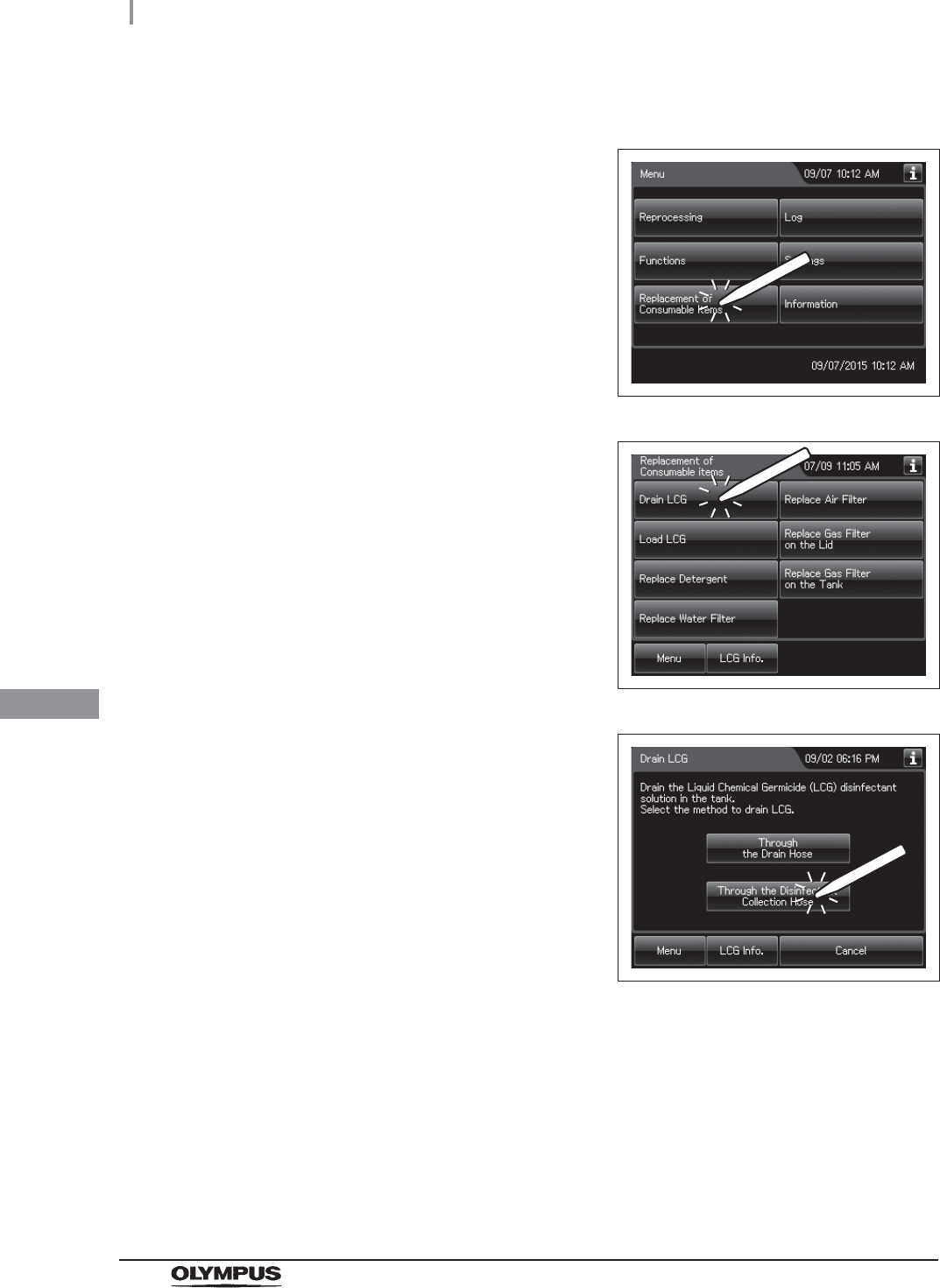
344
8.2 Replacing the disinfectant solution
OER-Elite OPERATION MANUAL
Ch.8
(b) Draining through the disinfectant collection hose
1Press the “Replacement of Consumable items”
button on the Menu screen.
Figure 8.1
2Press the “Drain LCG” button.
Figure 8.2
3Press the “Through the Disinfectant Collection
Hose” button.
Figure 8.3
4Step on the foot pedal to open the lid.
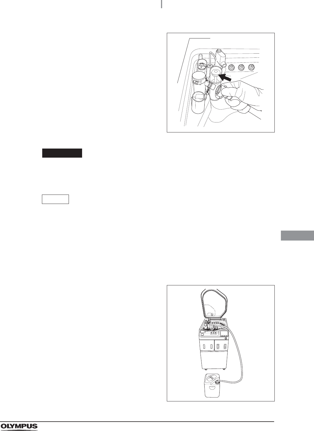
8.2 Replacing the disinfectant solution
345
OER-Elite OPERATION MANUAL
Ch.8
5While pulling the sleeve on the connector of the
disinfectant collection hose, connect the
connector into the disinfectant solution nozzle
inside the reprocessing basin. After connection,
pull the hose gently to make sure it is properly
attached.
Figure 8.4
WARNING
Be sure to attach the disinfectant solution nozzle cap to the original position.
Otherwise, the disinfectant solution will spatter.
NOTE
• If “DRAIN LCG” is selected and the FUNC START button is pressed without
connecting the disinfectant collection hose, the buzzer repeats short beeps,
disinfectant solution will fill the reprocessing basin and error code [E72] is
displayed. In this case, treat it by following the procedure in Section 13.2,
“Troubleshooting guide”.
• Make sure that the disinfectant collection hose is not kinked and the end of hose in
container is not clogged. Otherwise, the disinfectant solution will be spattered.
6Put the other end of the disinfectant collection
hose (the end without a connector) in a large
container that can hold up to 24 liters.
Figure 8.5
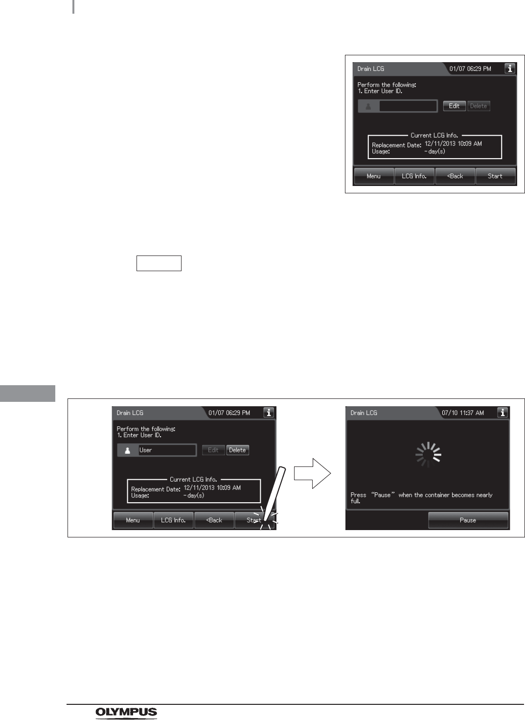
346
8.2 Replacing the disinfectant solution
OER-Elite OPERATION MANUAL
Ch.8
7Press the “Next” button repeatedly until the
touch screen display changes as shown below.
Figure 8.6
8Input the operator's user ID. For the detailed procedures, refer to Section 3.6,
“Entering ID” (If applicable).
NOTE
• The input of the user ID can be omitted by modifying the user ID input setting. For
details, refer to Section 4.5, “User ID Setting”.
• If the “Delete” button is pressed, the entered ID can be deleted.
9Press the “Start” button. The buzzer repeats short beeps to indicate that the
disinfectant solution drain process is underway, the touch screen changes the
following screen, and the disinfectant solution begins draining.
Figure 8.7
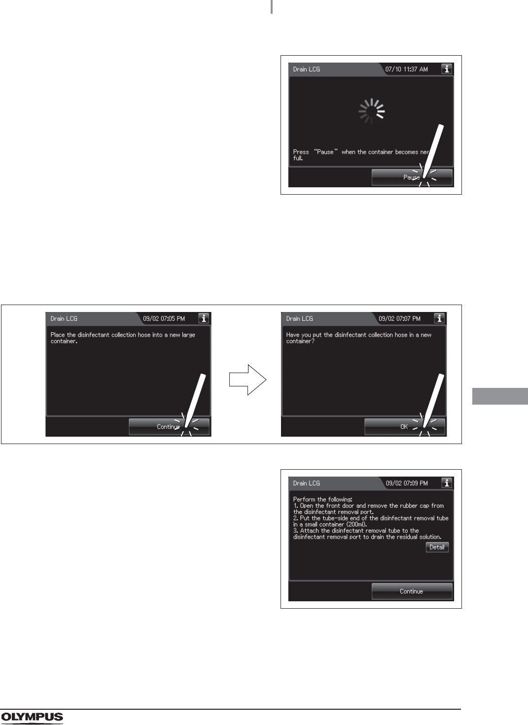
8.2 Replacing the disinfectant solution
347
OER-Elite OPERATION MANUAL
Ch.8
10 When the container (large) becomes nearly full,
press the “Pause” button on the touch screen to
interrupt the disinfectant solution collection.
Figure 8.8
11 Prepare a new container (large) and put the other end of the disinfectant collection
hose in it.
12 Hold the disinfectant collection hose so that it does not move, then press the
“Continue” button on the touch screen, and then press the “OK” button to restart
draining of the disinfectant solution.
Figure 8.9
13 When draining is stopped, the long buzzer
beeps, and the touch screen displays the
following screen.
Figure 8.10
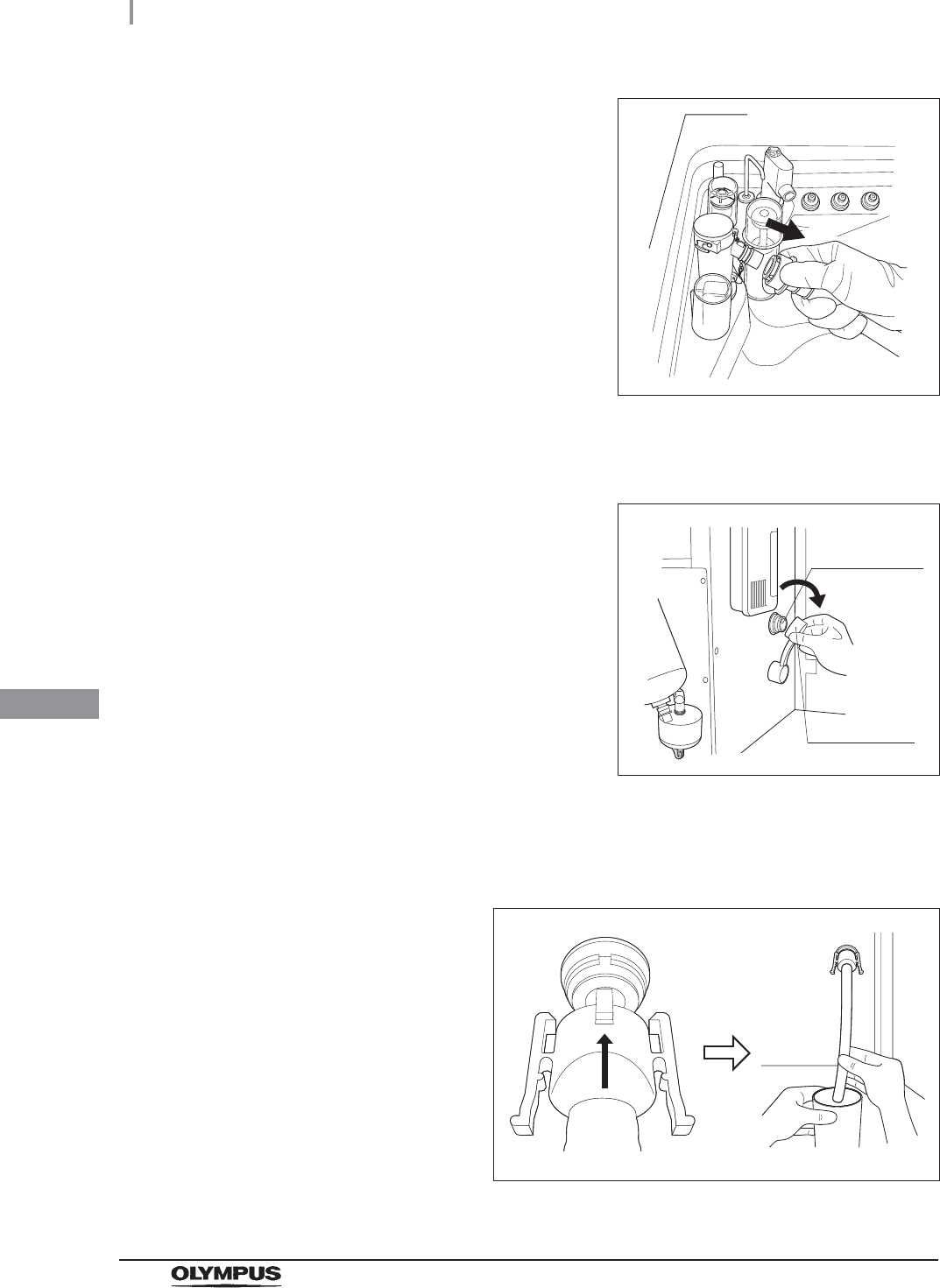
348
8.2 Replacing the disinfectant solution
OER-Elite OPERATION MANUAL
Ch.8
14 Pull the sleeve on the connector of the
disinfectant collection hose to disconnect it
from the disinfectant solution nozzle. Be sure to
drain the disinfectant solution that remains in
the disinfectant collection hose into the
container (large).
Figure 8.11
15 Rinse both the outside and inside of the disinfectant collection hose thoroughly in
running water, dry it thoroughly, and store it in a clean place.
16 Open the front door and remove the rubber cap
from the disinfectant removal port.
Figure 8.12
17 Put the tube-side end of the disinfectant removal tube in the beaker (small), and
connect the disinfectant removal tube to the disinfectant removal port to drain the
small amount of residual disinfectant solution from the disinfectant solution tank.
Figure 8.13
Disinfectant
removal port
Rubber cap
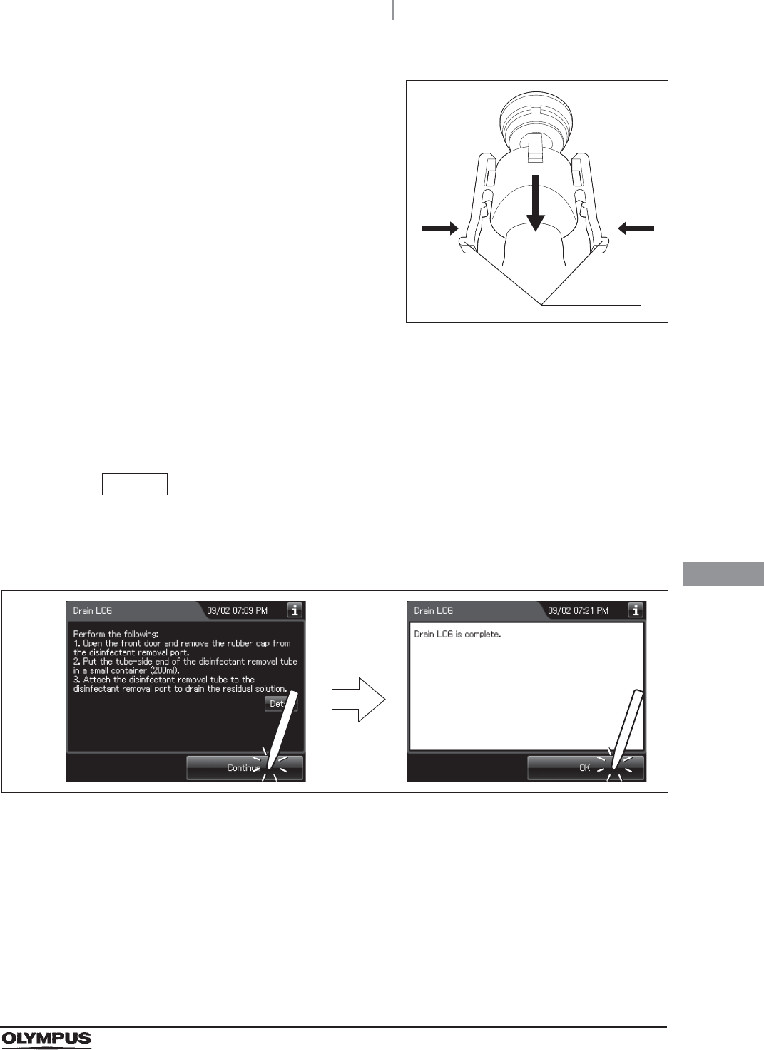
8.2 Replacing the disinfectant solution
349
OER-Elite OPERATION MANUAL
Ch.8
18 Hold the lock levers and slowly disconnect the
tube.
Figure 8.14
19 Rinse the disinfectant removal tube thoroughly under running water, dry it completely,
and store it in a clean place.
20 Wipe the disinfectant removal port with the clean cloth and attach the rubber cap to it.
21 Close the front door.
NOTE
The front door cannot be closed unless the rubber cap is attached.
22 Press the “Continue” button. Then, press the “OK” button.
Figure 8.15
Lock levers
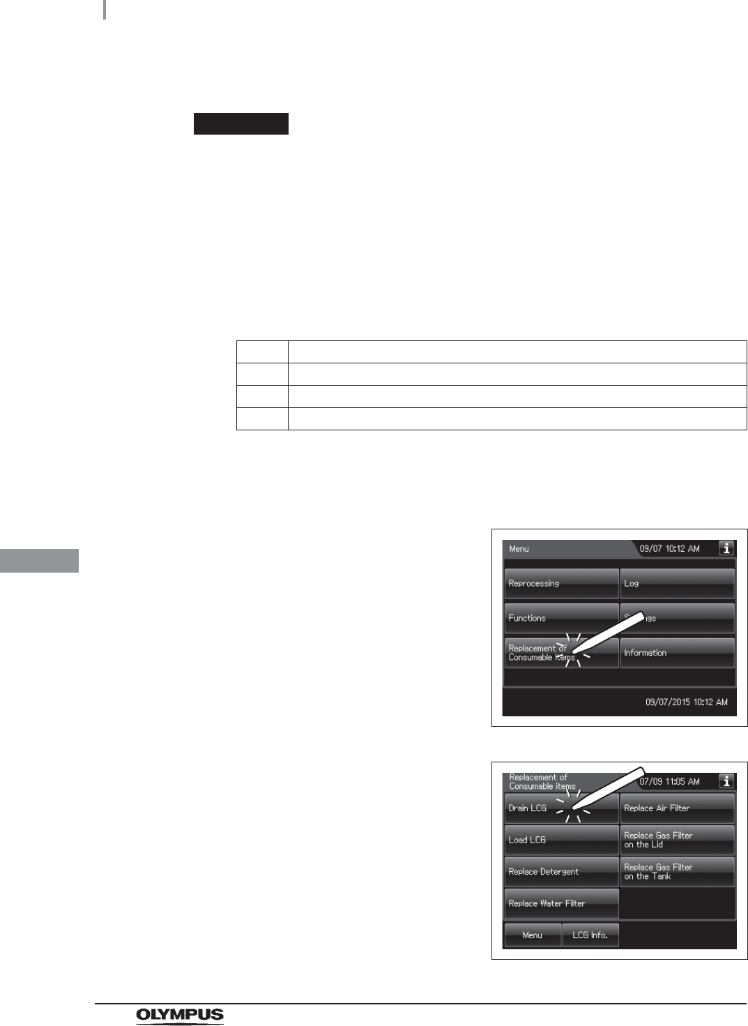
350
8.2 Replacing the disinfectant solution
OER-Elite OPERATION MANUAL
Ch.8
Draining through the drain hose
WARNING
• Do not push the disinfectant removal port with a finger while the rubber cap is not
attached. Otherwise, the disinfectant solution may flow out.
• To prevent peripheral device and facilities near the reprocessor from being
damaged by leaked disinfectant solution, do not remove the rubber cap from the
disinfectant removal port except when the disinfectant removal tube is connected.
(a) Required items
Table 8.3
(b) Draining through the disinfectant collection hose
Check Required items
Disinfectant removal tube
Beaker (small) with a capacity of about 200 ml, such as a beaker
Clean cloth
1Press the “Replacement of Consumable items”
button on the Menu screen.
Figure 8.16
2Press the “Drain LCG” button.
Figure 8.17
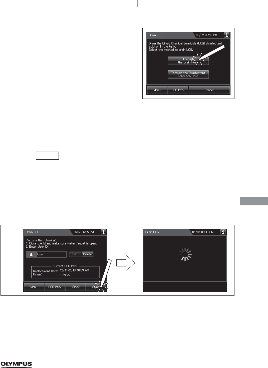
8.2 Replacing the disinfectant solution
351
OER-Elite OPERATION MANUAL
Ch.8
3Press the “Through the Drain Hose” button.
Figure 8.18
4Close the lid by pushing it until it clicks.
5Slowly open the water faucet.
6Input the operator's user ID. For the detailed procedures, refer to Section 3.6,
“Entering ID” (If applicable).
NOTE
• The input of the user ID can be omitted by modifying the user ID input setting. For
details, refer to Section 4.5, “User ID Setting”.
• If the “Delete” button is pressed, the entered ID can be deleted.
7Press the “Start” button. The buzzer beeps, the disinfectant solution begins draining,
and the reprocessing basin is rinsed. The touch screen displays the following screen
to indicate that the process is underway.
Figure 8.19
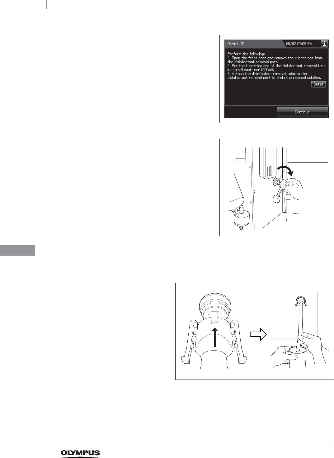
352
8.2 Replacing the disinfectant solution
OER-Elite OPERATION MANUAL
Ch.8
8When draining is stopped, the long buzzer
beeps, and the touch screen displays the
following screen.
Figure 8.20
9Open the front door and remove the rubber cap
from the disinfectant removal port.
Figure 8.21
10 Put the tube-side end of the disinfectant removal tube in the beaker (small), and
connect the disinfectant removal tube to the disinfectant removal port to drain the
small amount of residual disinfectant solution from the disinfectant solution tank.
Figure 8.22
Disinfectant
removal port
Rubber cap

8.2 Replacing the disinfectant solution
353
OER-Elite OPERATION MANUAL
Ch.8
11 Hold the lock levers and slowly disconnect the
tube.
Figure 8.23
12 Rinse the disinfectant removal tube thoroughly under running water, dry it completely,
and store it in a clean place.
13 Wipe the disinfectant removal port with the clean cloth and attach the rubber cap to it.
14 Close the front door.
NOTE
The front door cannot be closed unless the rubber cap is attached.
15 Press the “Continue” button, and then press the “OK” button.
Figure 8.24
Lock levers
354
8.2 Replacing the disinfectant solution
OER-Elite OPERATION MANUAL
Ch.8
Load the disinfectant solution
WARNING
• Before handling the disinfectant solution, read the cautions carefully and use as
instructed. It is especially important to know what to do if the disinfectant solution
comes in contact with your skin and eyes.
• Always use disinfectant that has been validated by Olympus. High-level
disinfectants that are not validated by Olympus for use in the OER-Elite may be
unsafe and ineffective due to improper dilution, incorrect contact time and
temperature, excessive foaming, inadequate rinse, and therefore may compromise
patient safety. Use of a high-level disinfectant that has not been validated by
Olympus may also damage internal OER-Elite components (e.g., seals, valves,
etc.) and the endoscopes being reprocessed.
• When handling the disinfectant solution, wear personal protective equipment to
prevent any disinfectant from getting on your skin and eyes or being inhaled. Avoid
direct physical contact and inhalation of vapors. If any disinfectant solution gets in
your eyes, immediately rinse with a large amount of fresh water and then consult a
medical specialist. Wear personal protective equipment, such as eyewear, face
mask, moisture-resistant clothing, and chemical-resistant gloves that fit properly
and are long enough so that your skin and eyes is not exposed. All personal
protective equipment should be inspected before use and replaced periodically
before it is damaged.
• When using the disinfectant solution and alcohol, Olympus recommends the use of
gas filters and running this reprocessor in well-ventilated areas.
Wear a face mask, gloves, and protective clothes to minimize aspiration and
skin contact.
Wear goggles for eye protection.
Refer to the following association’s guidelines related to ventilation:
If the person operating the reprocessor exhibits an allergic reaction or symptoms,
no matter how slight, they should discontinue the task they are performing and
vacate the room.
SGNA (Society of Gastroenterology Nurses and Associates)
ASGE (American Society of Gastroenterological Endoscopy)
APIC (Association for Professionals of Infection Control and Epidemiology)
AORN (Association of Preoperative Registered Nurses)
ASTM (American Society for Testing and Materials)
OSHA (Occupational Safety and Health Administration)
ACGIH (American Conference of Governmental Industrial Hygienists)
NIOSH (National Institute for Occupational Safety and Health)
AIA (American Institute of Architects)
8.2 Replacing the disinfectant solution
355
OER-Elite OPERATION MANUAL
Ch.8
WARNING
• Effective reprocessing cannot be guaranteed when a nonvalidated disinfectant
solution is used. Reprocessor malfunction may also result.
• Follow the disinfectant manufacturer’s instructions for any preparation or activation
required prior to loading into the OER-Elite.
• If the disinfectant solution in the cassette bottles has not completely drained after
preparation of disinfectant solution, do not use the reprocessor and contact
Olympus. Inappropriate preparation of disinfectant solution will prevent proper
endoscope reprocessing.
• Do not touch inside the caps of cassette bottles. Do not push or apply strong
pressure to the bottle. Otherwise, disinfectant solution may leak from the bottle.
CAUTION
• To avoid malfunction, do not attempt to pull out the disinfectant bottle drawer while
it is locked.
• Do not put your hand into the disinfectant bottle drawer or near the cassette bottle
cutters. Irritation of skin due to contact with concentrated disinfectant solution,
injury by touching a projection, or malfunction of this reprocessor may result.
Required items
Table 8 . 4
NOTE
For Acecide-C high level disinfectant solution, refer to Section 2.8, “Consumable
accessories (Optional)”.
Check Required items
Acecide-C high level disinfectant solution
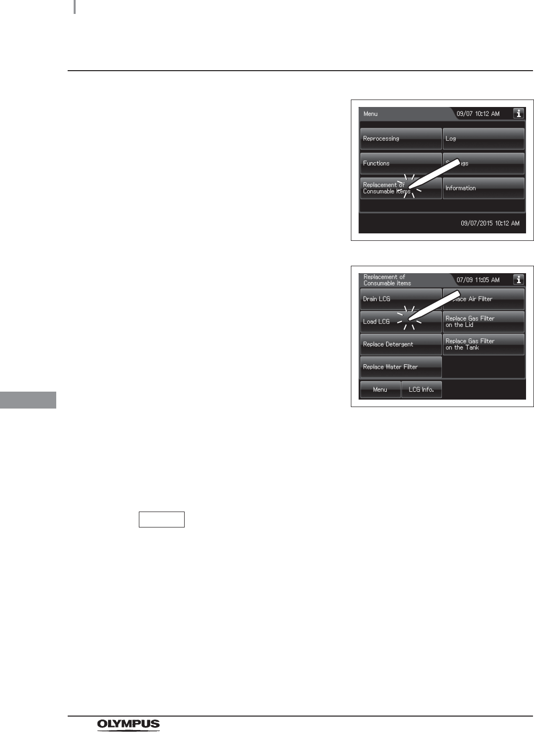
356
8.2 Replacing the disinfectant solution
OER-Elite OPERATION MANUAL
Ch.8
Setting the disinfectant solution
1Press the “Replacement of Consumable Items”
button on the Menu screen.
Figure 8.25
2Press the “Load LCG” button.
Figure 8.26
3Close the lid by pushing until it clicks.
4Make sure that the water faucet is open.
5Input the operator’s user ID. For the detailed procedures, refer to Section 3.6,
“Entering ID” (If applicable).
NOTE
• The input of the user ID can be omitted by modifying the user ID input setting. For
details, refer to Section 4.5, “User ID Setting”.
• If the “Delete” button is pressed, the entered ID can be deleted.
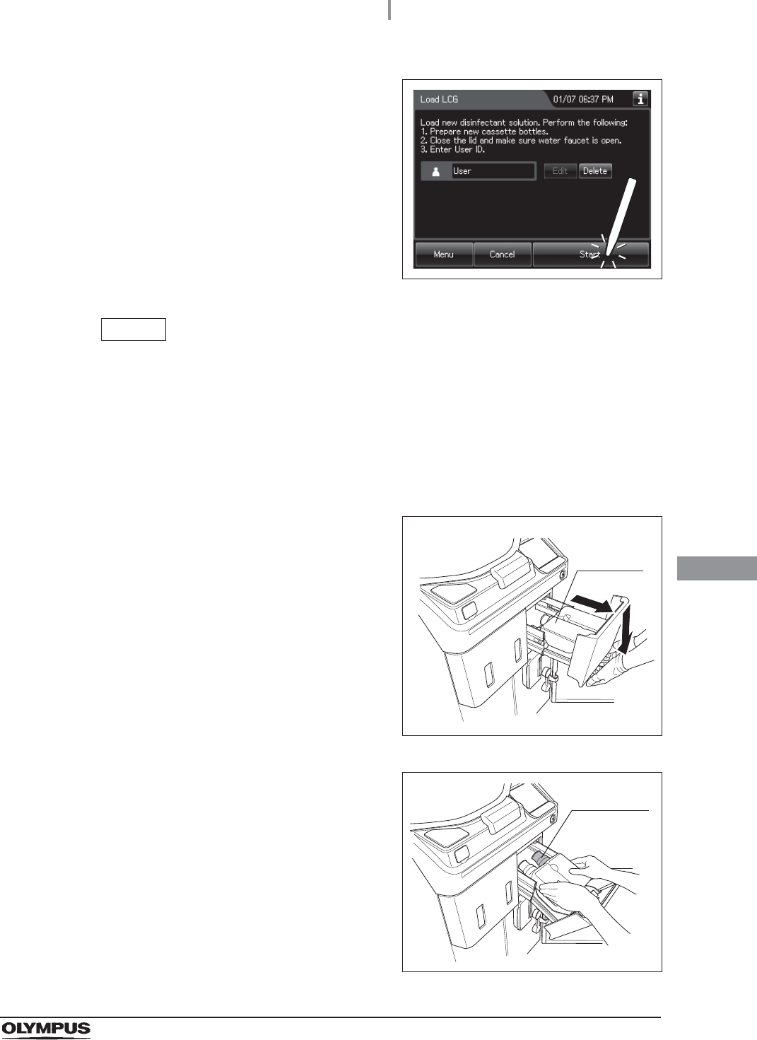
8.2 Replacing the disinfectant solution
357
OER-Elite OPERATION MANUAL
Ch.8
6Press the “Start” button to unlock the
disinfectant bottle drawer.
Figure 8.27
NOTE
• The Load LCG cannot be started unless the disinfectant solution tank is empty.
• If the shelf-life and/or lot number management of the disinfectant solution are
activated, the shelf-life and/or lot number of the disinfectant solution can be
entered after pressing the “Next” button. For entering the shelf-life and/or lot
number of the disinfectant solution, refer to “When entering the shelf-life and/or
lot number of the disinfectant solution:” on page 361.
7Pull out the disinfectant bottle drawer.
Figure 8.28
8To remove the empty cassette bottles from the
disinfectant bottle drawer, position the bottle
mouths upward so that the disinfectant solution
does not come out.
Figure 8.29
Cassette
bottles
Purple cap
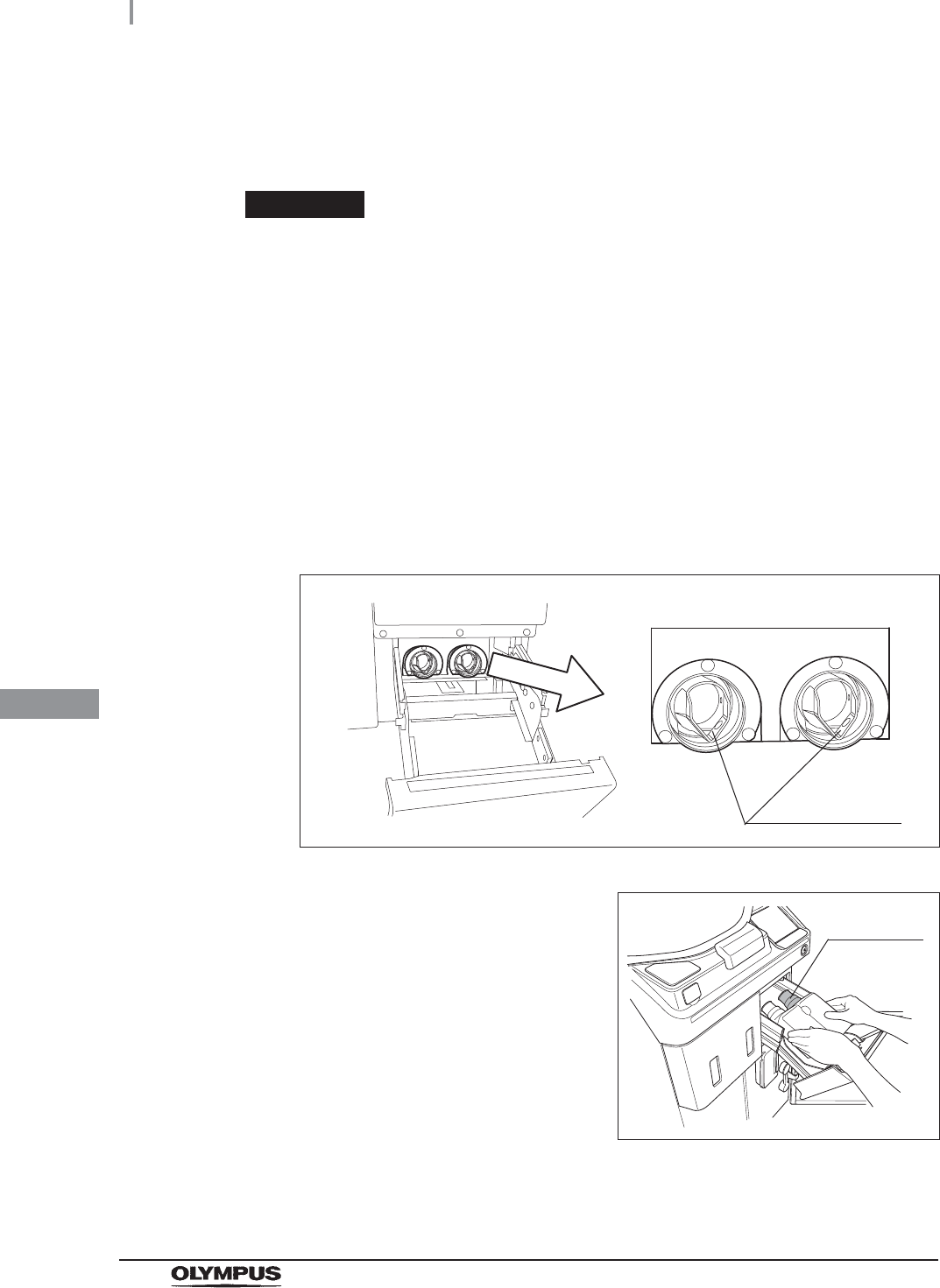
358
8.2 Replacing the disinfectant solution
OER-Elite OPERATION MANUAL
Ch.8
9If any disinfectant solution spills, wipe it away with a clean cloth. If the disinfectant
bottle drawer is dirty, clean using a clean cloth moistened with neutral detergent
solution and then wipe with a clean cloth.
WARNING
• Do not put your hand behind the disinfectant bottle drawer. Irritation of skin due to
contact with concentrated disinfectant solution, injury by touching a projection, or
malfunction of this reprocessor may result.
• If the cassette cutters are abnormal, do not use the reprocessor and contact
Olympus. If the cassette cutters are abnormal, the disinfectant solution cannot be
properly prepared. This will prevent effective endoscope reprocessing and may
cause the reprocessor to malfunction.
10 Check the two cassette cutters (blades for ripping caps on disinfectant cassette
bottles) placed at the back of the disinfectant bottle drawer. Compare the two blades
and make sure that neither cutter is bent, cracked, or deformed. Changes in color are
not a malfunction.
Figure 8.30
11 Hold the new disinfectant cassette bottles
together and place them on the disinfectant
bottle drawer so that the bottle with the purple
cap is on the right.
Figure 8.31
Cassette cutters
Purple cap
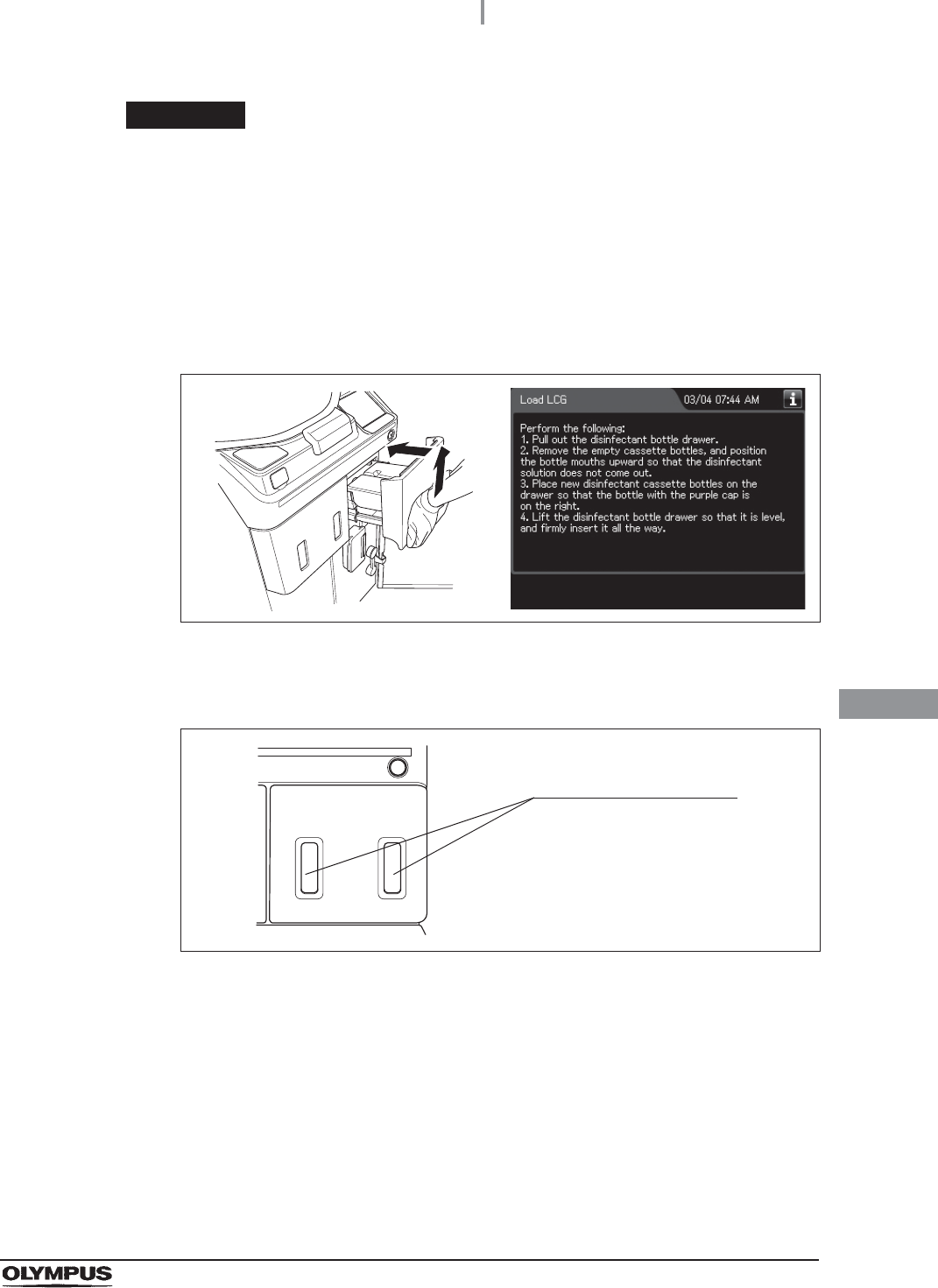
8.2 Replacing the disinfectant solution
359
OER-Elite OPERATION MANUAL
Ch.8
CAUTION
When pushing in the disinfectant bottle tray, hold the disinfectant drawer
horizontally and push it all the way in. Otherwise, the disinfectant cassette bottle
would be unable to be opened and the disinfectant solution would be unable to be
prepared normally.
12 Lift the disinfectant bottle drawer so that it is level, and insert it all the way. The buzzer
should beep, the drawer should lock, and the disinfectant cassette bottles should
open automatically.
Figure 8.32
13 Look at the disinfectant bottle drawer and check the windows to verify that the
disinfectant solution in both bottles has decreased.
Figure 8.33
Disinfectant bottle drawer
check windows
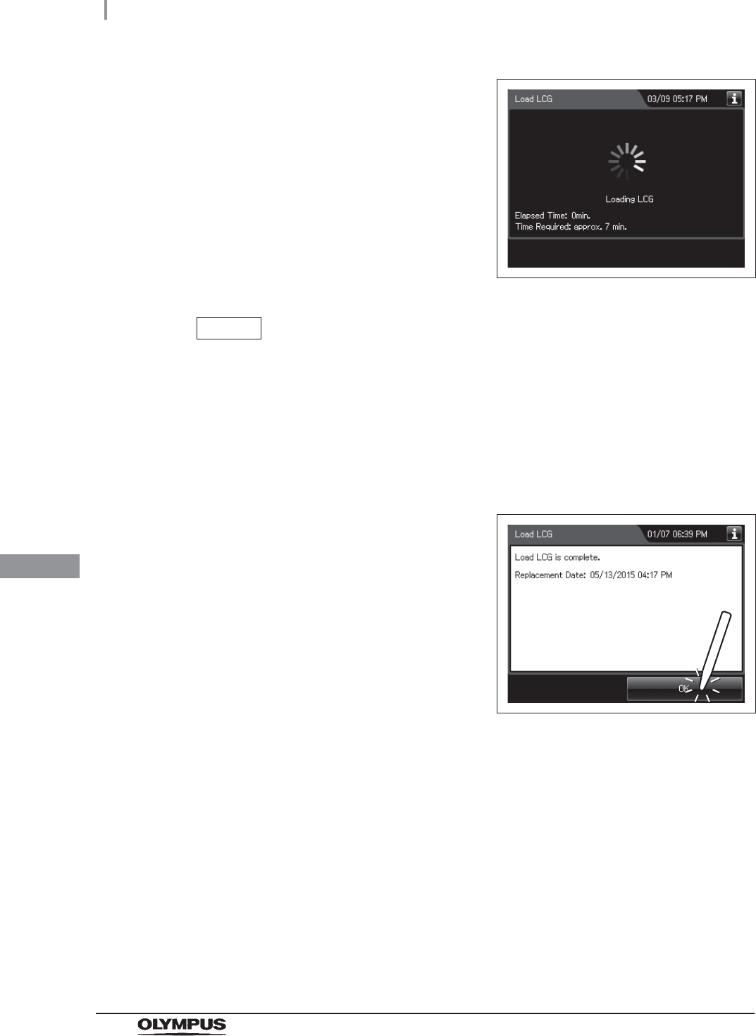
360
8.2 Replacing the disinfectant solution
OER-Elite OPERATION MANUAL
Ch.8
14 The buzzer generates short beeps and the
touch screen displays a screen indicating that
the disinfectant solution is being prepared.
Figure 8.34
NOTE
• Preparation of disinfectant solution includes single rinse process to rinse the
reprocessing basin. While executing the preparation of disinfectant solution,
buzzer beeps intermittently and the main control panel displays as shown in
Figure 8.34. STOP button is deactivated during the process.
• The required time for preparation of disinfectant solution may vary depending on
the water supply condition.
15 The touch screen displays the following screen.
This screen indicates the process is completed.
Press the “OK” button.
Figure 8.35
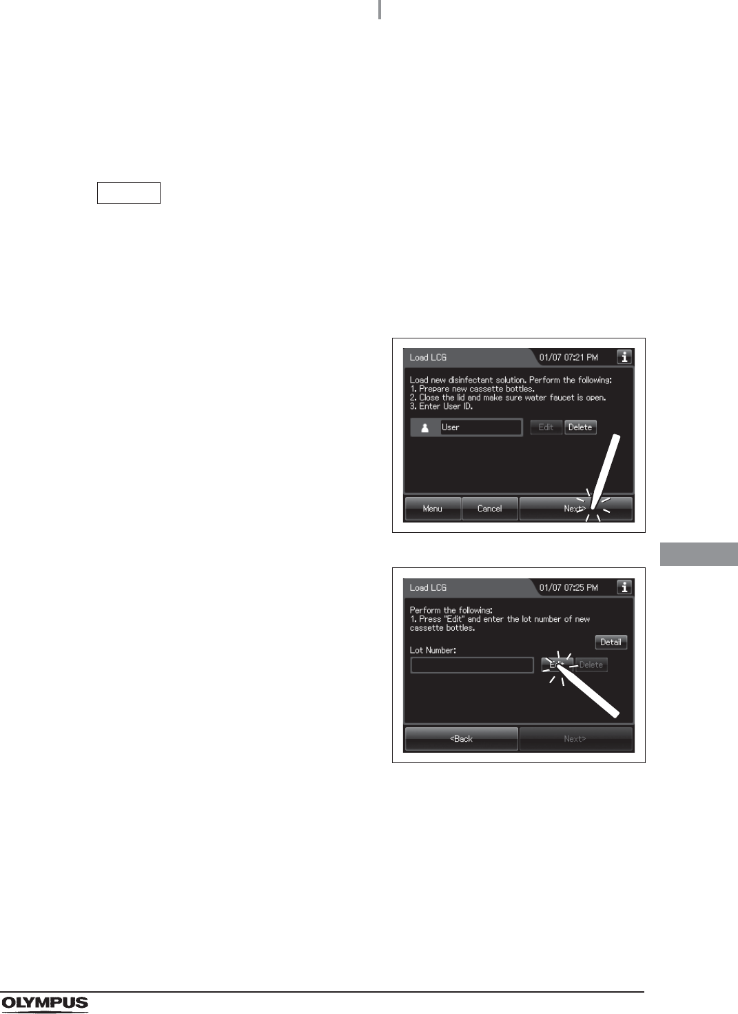
8.2 Replacing the disinfectant solution
361
OER-Elite OPERATION MANUAL
Ch.8
When entering the shelf-life and/or lot number of the disinfectant
solution:
If the shelf-life and lot number management is activated, enter the shelf-life and/or lot number
according to the following procedure.
NOTE
• The lot number and shelf-life are printed on the bottle.
• The shelf life and lot number of the disinfectant solution can be recorded. For the
setting change method, refer to Section 4.13, “LCG lot number and shelf-life
management”.
1If the shelf-life and/or lot number management
of the disinfectant solution are activated, the
touch screen displays a screen as shown in
following figure at Step 6 in “Setting the
disinfectant solution” on page 357. Press the
“Next” button. When the lot number
management of the disinfectant solution is
activated, go to Step 2. When the lot number
management of the disinfectant solution is
inactivated, go to Step 5.
Figure 8.36
2Press the “Edit” button to display the Lot No.
Entry screen.
Figure 8.37
3Enter the lot number of the disinfectant solution by operating the software keyboard
on the touch screen and press the “Save” button.
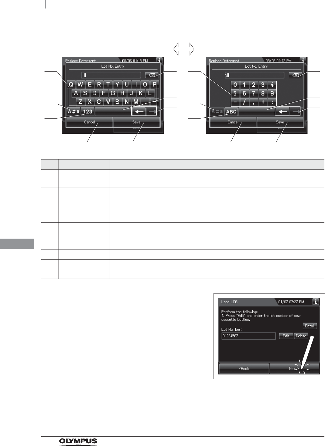
362
8.2 Replacing the disinfectant solution
OER-Elite OPERATION MANUAL
Ch.8
No. Button Note
1 Alphabet/
Numeral key
Enter an alphabet or a numeral.
2 Uppercase/
Lowercase button
Press “Uppercase/lowercase” button to switch alphabet character on the soft keyboard
between uppercase and lowercase characters.
3 Numeric/
Alphabetic button
Press “Numeric or Alphabetic” button to switch the input mode between numeric and
alphabetic.
4 Backspace button Press the “Backspace” button to delete the character to the left of the cursor.
When a cursor is on the left edge, this button turns gray and becomes unavailable.
5 Space button Press the “Space” button to insert a space character.
6 Cursor move button Press the cursor move button to move the cursor the left or right.
7 Cancel button Return to the previous screen without saving the setting value.
8 Save button Return to the previous screen and save the entered value.
4Press the “Next” button. If the Expiration Date
management of the disinfectant solution is
activated, go to Step 5. If the Expiration Date
management of the disinfectant solution is
inactivated, go to Step 6.
Figure 8.38
41
2
3
5
6
7 8
41
2
3
5
6
7 8
Alphabet input Numeral input
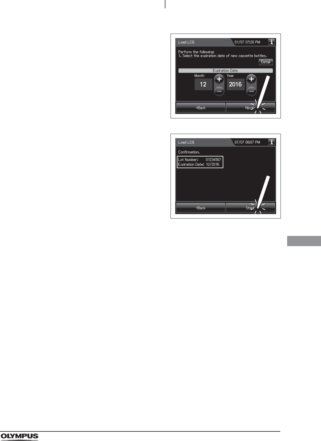
8.2 Replacing the disinfectant solution
363
OER-Elite OPERATION MANUAL
Ch.8
5Enter the Expiration Date of the disinfectant
solution. Press the “+” button to increase or the
“–” button to decrease. And then press the
“Next” button.
Figure 8.39
6Check the displayed lot number and the
expiration date, and press the “Start” button.
Go to Step 7 in “Setting the disinfectant
solution” on page 357.
Figure 8.40
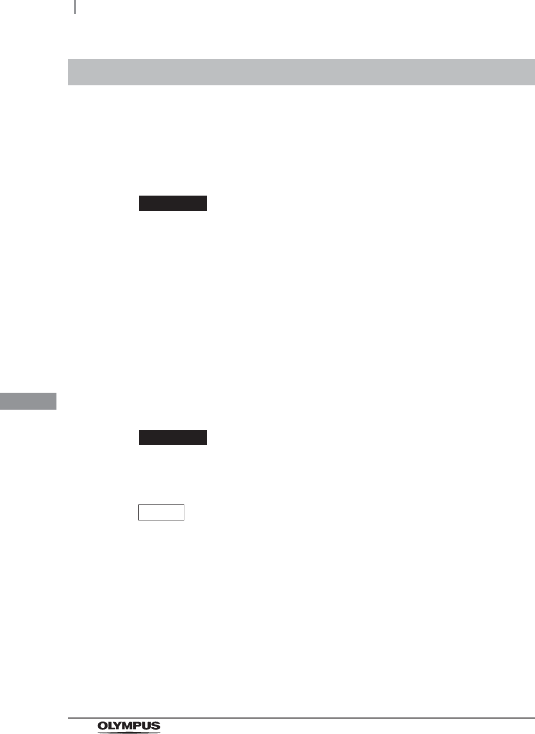
364
8.3 Replacing the detergent tank
OER-Elite OPERATION MANUAL
Ch.8
When the detergent level can no longer be visualized through the detergent tank check window or the
touch screen displays the message screen “Detergent cannot be supplied” after the start of a process,
replace the detergent tank.
To create the record of the replacement of the detergent tank, select “Replace Detergent” in the
Replacement of Consumable Items menu.
WARNING
• Before handling the detergent, read the cautions carefully and use it as instructed.
It is especially important to know what to do if the detergent solution comes in
contact with your skin and eyes.
• Always use an Olympus-validated detergent. Otherwise, the endoscope may not
be properly cleaned and as a result, the endoscope may not achieve reprocessing.
• When handling the detergent, always wear appropriate personal protective
equipment, such as eyewear, face mask, moisture-resistant clothing, and
chemical-resistant gloves that fit properly and are long enough so that your skin
and eyes is not exposed. All personal protective equipment should be inspected
before use and replaced periodically before it is damaged.
• To prevent the detergent from leaking, do not tilt the detergent tank when there is
detergent inside.
CAUTION
Do not attempt to detergent into the detergent tank. The detergent tank is
disposable and it is not intended to be reused.
NOTE
• When the detergent counter setting and/or detergent shelf life setting is activated,
the detergent replacement indicator can be displayed on the top right of the touch
screen and on the “Replace Detergent” button on the Replacement of Consumable
Items menu when the counter setting value or shelf life setting value is reached.
For the detergent counter setting, refer to Section 4.10, “Detergent replacement
indicator”. For the shelf life setting, refer to Section 4.11, “Detergent lot number and
shelf-life management”.
• If reprocessing is initiated without detergent, the reprocessing is stopped with
displaying the message and the detergent replacement indicator.
8.3 Replacing the detergent tank
8.3 Replacing the detergent tank
365
OER-Elite OPERATION MANUAL
Ch.8
NOTE
• The detergent tank can hold about 2.8 L (95 ounces) of detergent (which can be
used for approximately 30 reprocessing operations).
• When reprocessing is performed with newly-installed reprocessor or with
reprocessor after Section 9.9, “Preparing the reprocessor for long-term storage” is
performed, reprocessing may stop with the message screen “Detergent cannot be
supplied” even though there is enough detergent in the tank. To solve this problem,
refer to Section 13.2, “Troubleshooting guide”, “Message, caution, and warning
screens” on page 621.
• The shelf life and lot number of the detergent tank can be recorded. For the setting
change method, refer to Section 4.11, “Detergent lot number and shelf-life
management”.
• If reprocessing is initiated without detergent, error code [E095] is displayed and the
reprocessing is stopped. The detergent replacement indicator on the main panel
blinks.
• When reprocessing is performed with newly-installed reprocessor or with
reprocessor after Section 9.9, “Preparing the reprocessor for long-term storage” is
performed, reprocessing may stop with error code [E095] displayed even though
there is enough detergent in the tank. Refer to “When the “Message 093” is
displayed” on page 635 to solve this problem.
Required item
Table 8 . 5
NOTE
For Olympus-validated detergent, refer to Section 2.8, “Consumable accessories
(Optional)”.
Check Required items
Olympus-validated detergent
Clean gauze or similar cloth.
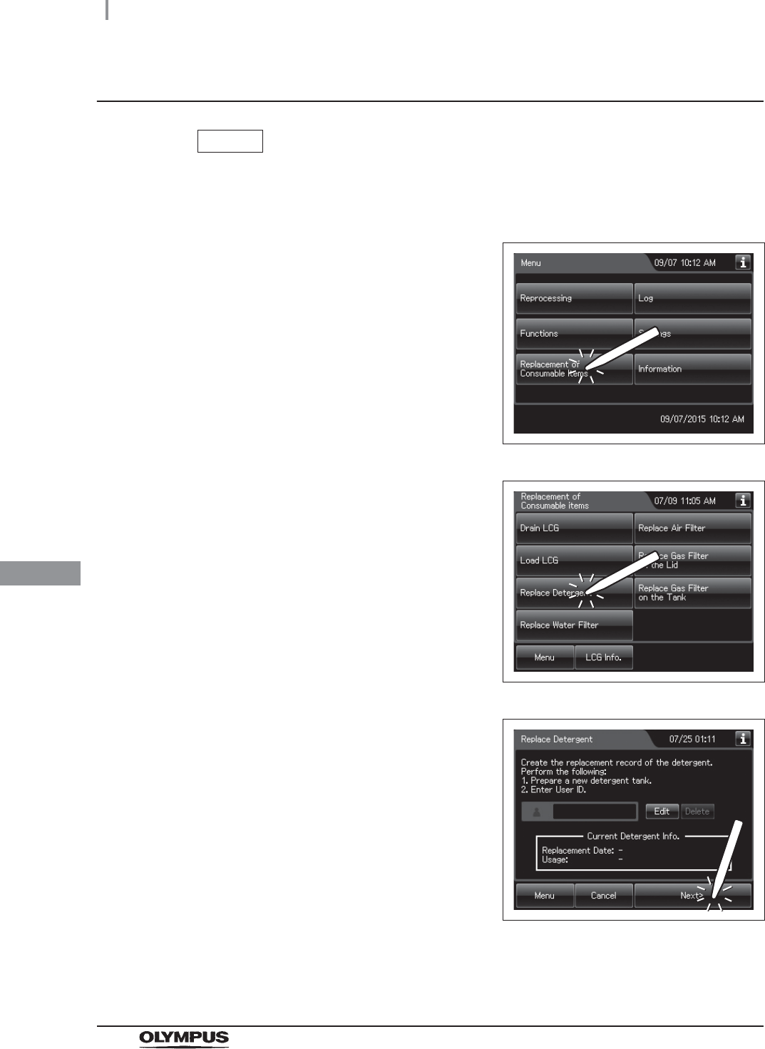
366
8.3 Replacing the detergent tank
OER-Elite OPERATION MANUAL
Ch.8
Replacing the detergent tank
NOTE
If you do not need to create the record of the replacement of the detergent tank, the
following operations of GUI can be skipped.
1Press the “Replacement of Consumable Items”
button on the Menu screen.
Figure 8.41
2Press the “Replace Detergent” button.
Figure 8.42
3Input the operator's user ID. For the detailed
procedures, refer to Section 3.6, “Entering ID”
(If applicable).
Figure 8.43
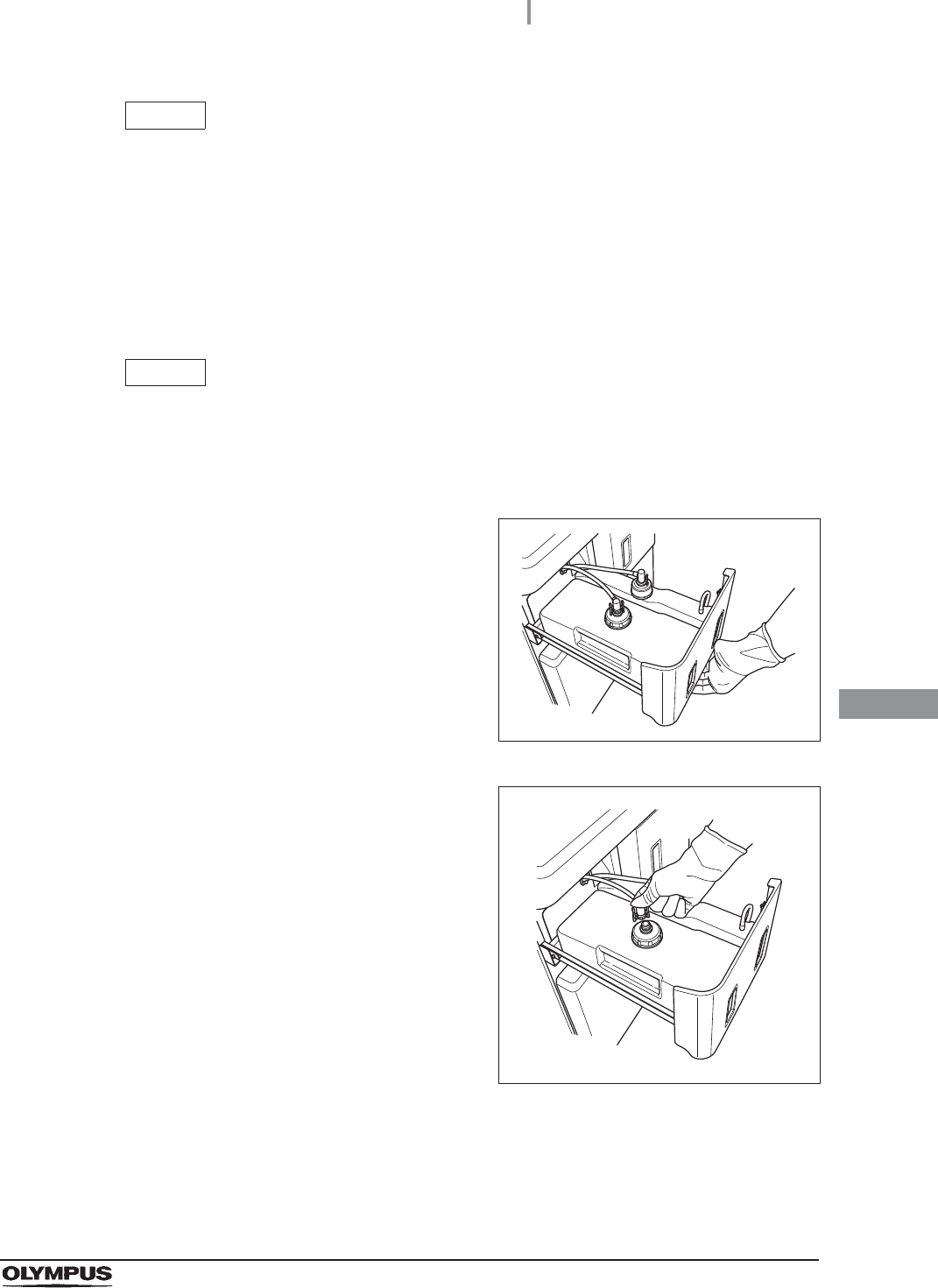
8.3 Replacing the detergent tank
367
OER-Elite OPERATION MANUAL
Ch.8
NOTE
• The shelf life and lot number of the detergent tank can be recorded. For the setting
change method, refer to Section 4.11, “Detergent lot number and shelf-life
management”.
• The input of the user ID can be omitted by modifying the user ID input setting. For
details, refer to Section 4.5, “User ID Setting”.
• If the “Delete” button is pressed, the entered ID can be deleted.
NOTE
When the detergent shelf life and lot number management is activated, the shelf
and lot number of detergent tank are entered after Step 14. For details, refer to
“When entering the lot number of detergent and shelf life:” on page 372.
4Hold the section marked “PULL” of the
detergent/alcohol drawer and pull it out.
Figure 8.44
5Push the lock lever on the connector of the
tube connected to the detergent tank to detach
the tube.
Figure 8.45
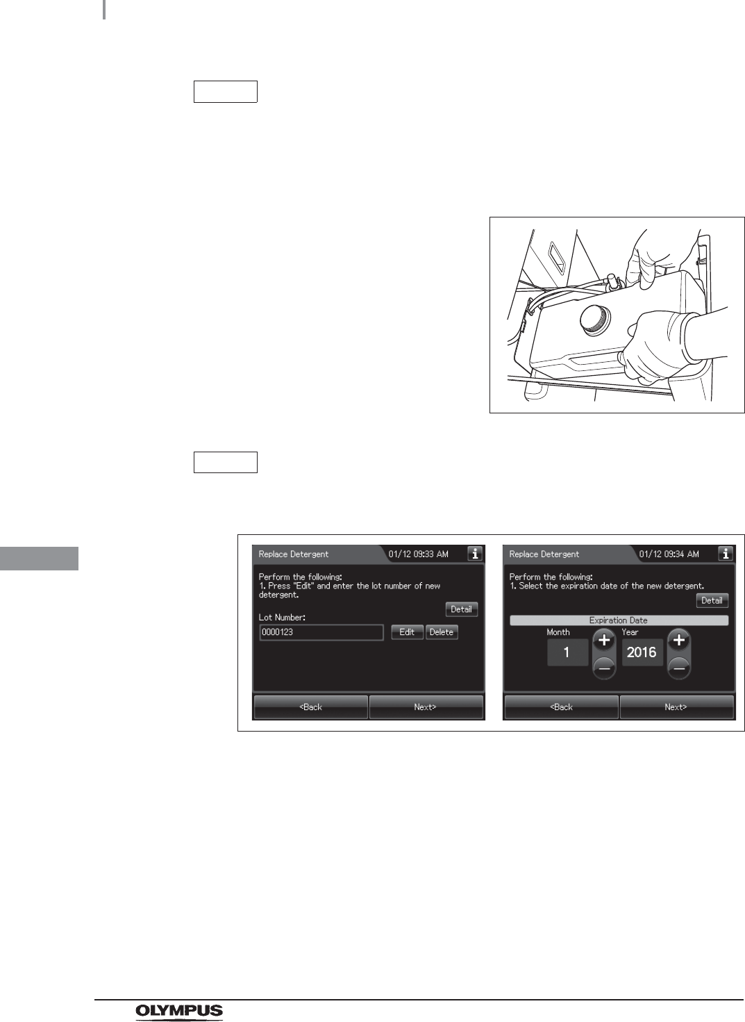
368
8.3 Replacing the detergent tank
OER-Elite OPERATION MANUAL
Ch.8
NOTE
If a few drops of detergent drip from the connector, wipe it with a piece of clean
gauze or similar cloth.
6Remove the detergent tank.
7Place a new detergent tank on the left side of
the detergent/alcohol drawer.
Figure 8.46
NOTE
Refer the lot number of new detergent tank. Press “Edit” and enter the lot number
and expiration date.
Figure 8.47
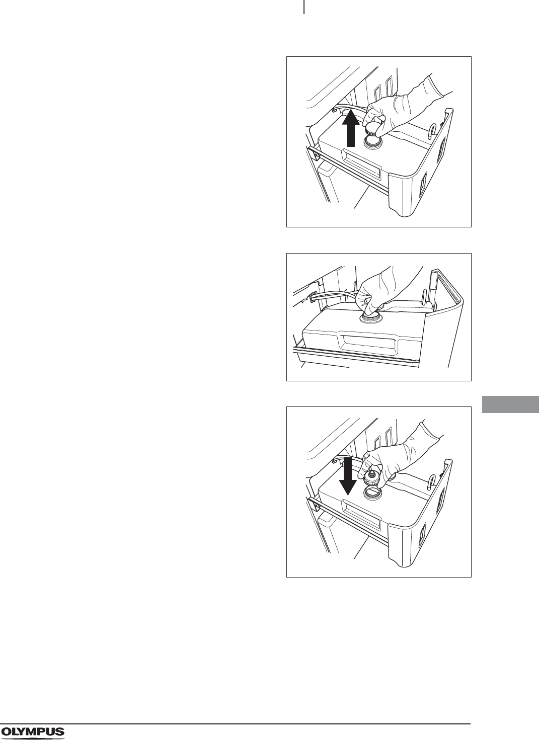
8.3 Replacing the detergent tank
369
OER-Elite OPERATION MANUAL
Ch.8
8Detach the cap of the new detergent tank.
Figure 8.48
9Remove the seal on the new detergent tank.
Figure 8.49
10 Attach the cap with connector to the new
detergent tank.
Figure 8.50
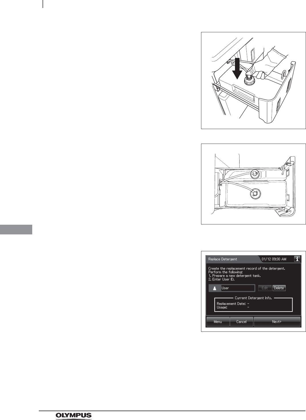
370
8.3 Replacing the detergent tank
OER-Elite OPERATION MANUAL
Ch.8
11 Insert the white connector into the connector on
the detergent tank until it clicks.
Figure 8.51
12 Turn the connector to correct tube orientation
as shown below. Confirm that the tube is not
bent.
Figure 8.52
13 Close the detergent/alcohol drawer.
14 Press the “Next” button on the touch screen.
Figure 8.53
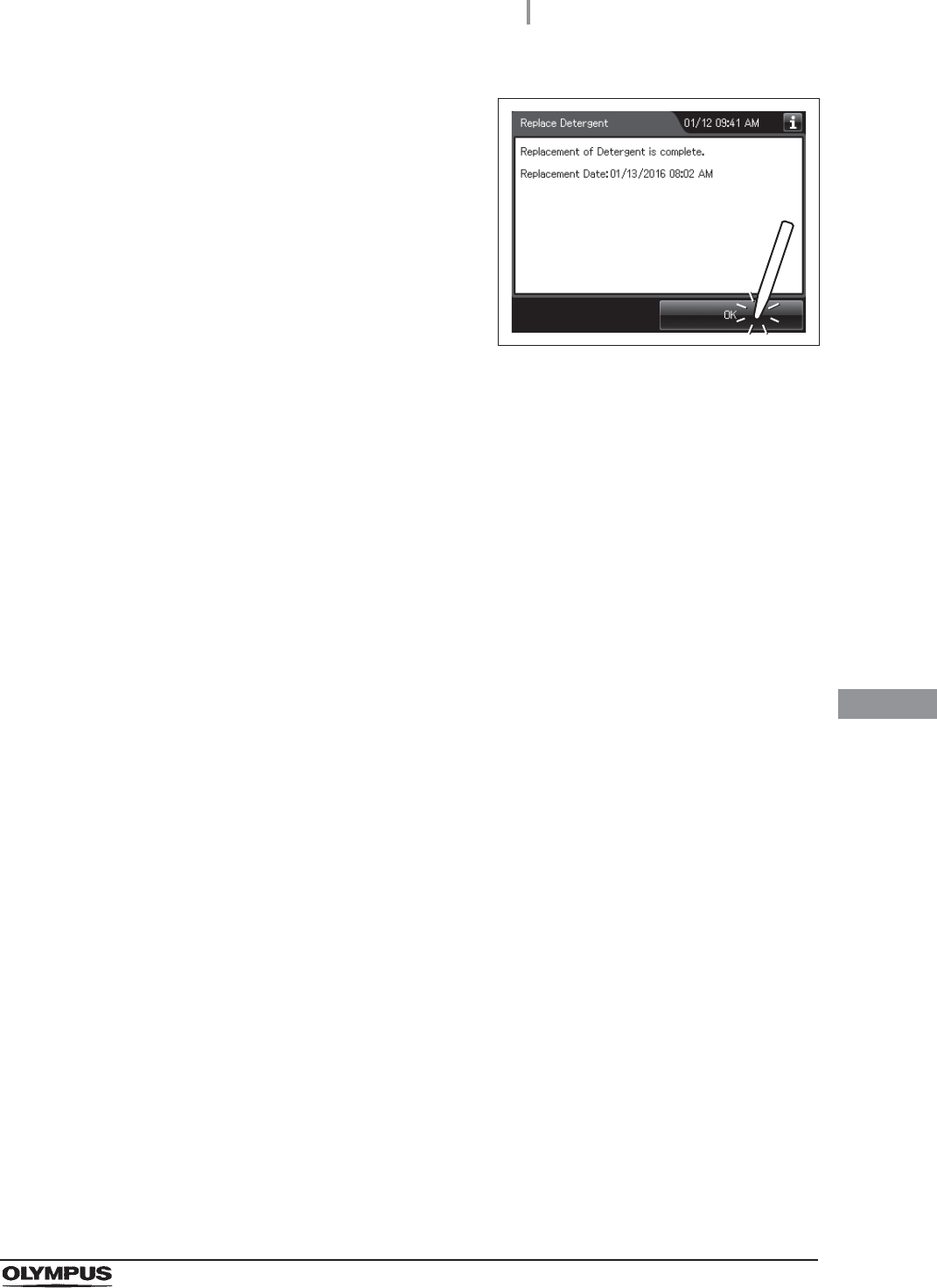
8.3 Replacing the detergent tank
371
OER-Elite OPERATION MANUAL
Ch.8
15 Press the “OK” button.
Figure 8.54
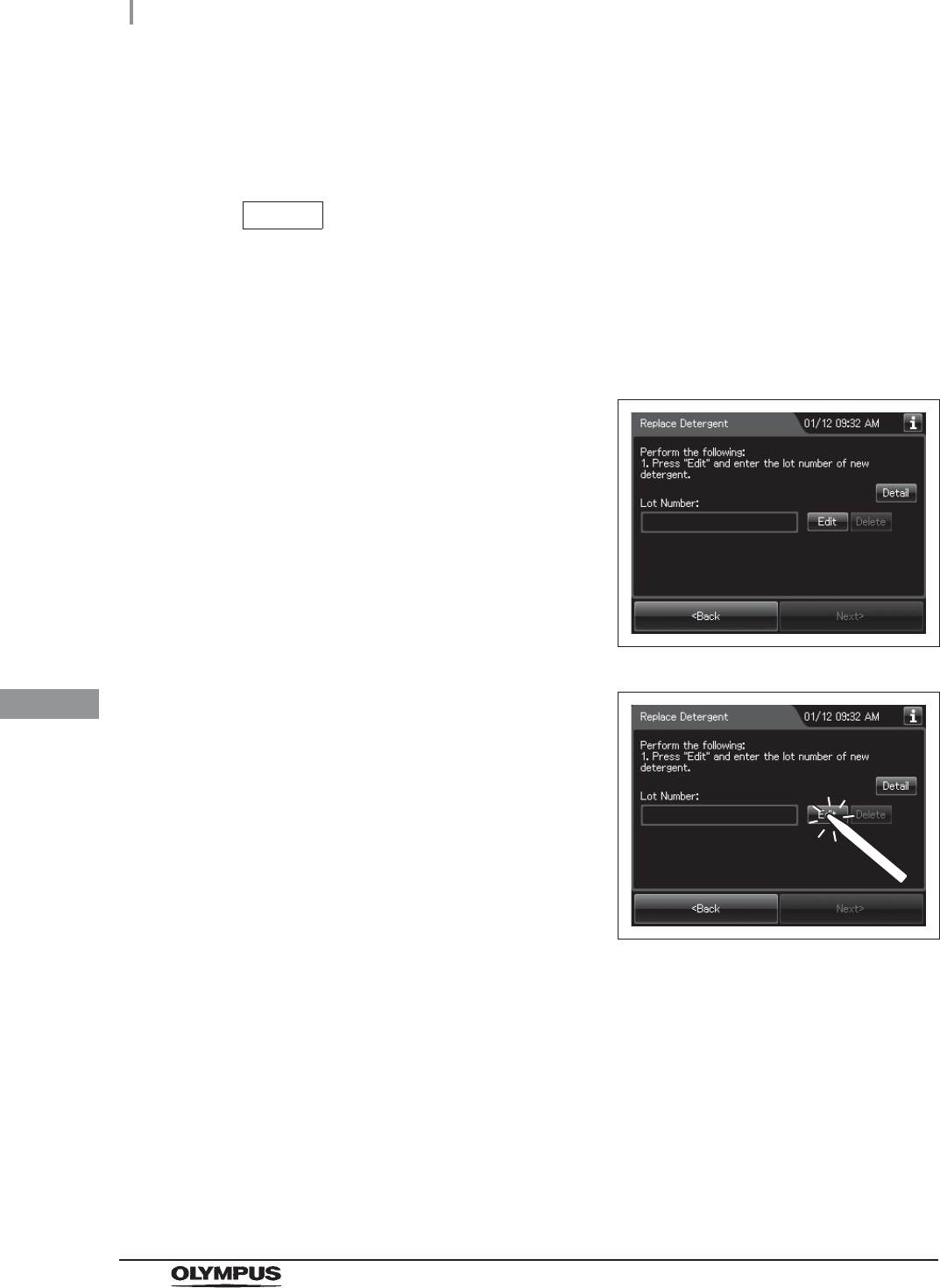
372
8.3 Replacing the detergent tank
OER-Elite OPERATION MANUAL
Ch.8
When entering the lot number of detergent and shelf life:
If the lot number of detergent and Shelf life management is activated, enter the lot number
and/or shelf life according to the following procedure.
NOTE
• The shelf life and lot number of the detergent tank can be recorded. For the setting
change method, refer to Section 4.11, “Detergent lot number and shelf-life
management”.
• The lot number and shelf life are printed on the detergent tank.
1If the lot number management of detergent is
activated, the touch screen displays the screen
as shown in following figure after Step 14 in
“Replacing the detergent tank” on page 370.
If the lot number management of the detergent
is inactivated, go to Step 5.
Figure 8.55
2Press the “Edit” button to display the lot number
entry screen.
Figure 8.56
3Enter the lot number of the new detergent by operating the software keyboard on the
touch screen and press the “Save” button.
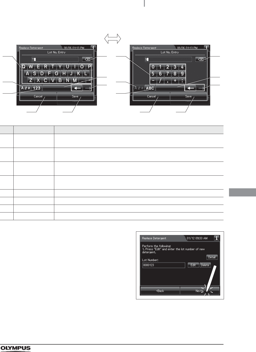
8.3 Replacing the detergent tank
373
OER-Elite OPERATION MANUAL
Ch.8
No. Button Note
1 Alphabet/
Numeral key
Enter the alphabet or a numeral.
2 Uppercase/
Lowercase button
Press “Uppercase/lowercase” button to switch alphabet character on the soft keyboard
between uppercase characters and lowercase characters.
3 Numeric/
Alphabetic button
Press “Numeric or Alphabetic” button to switch the input mode between a numeral and
the alphabet.
4 Backspace button Press the “Backspace” button to delete the left character of a cursor.
When a cursor is on the left edge, this button turns gray and becomes unavailable.
5 Space button Press the “Space” button to insert a space character.
6 Cursor move button Press the cursor move button to move the cursor left or right.
7 Cancel button Return to the previous screen without saving the setting value.
8 Save button Return to the previous screen and save the entered value.
4Press the “Next” button. If the Expiration Date
management of the detergent is activated, go
to Step 5. If the Expiration Date management of
the detergent is inactivated, go to Step 6.
Figure 8.57
41
2
3
5
6
7 8
41
2
3
5
6
7 8
Alphabet input Numeral input
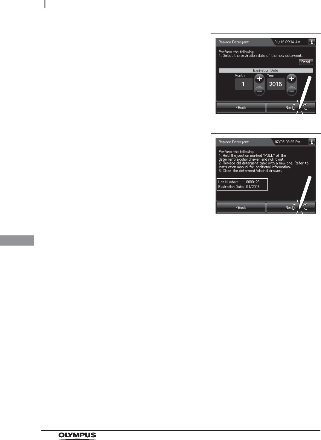
374
8.3 Replacing the detergent tank
OER-Elite OPERATION MANUAL
Ch.8
5Enter the Expiration Date of the detergent.
Press the “Plus” button to increase or the
“Minus” button to decrease. Then press the
“Next” button.
Figure 8.58
6Check the displayed lot number and the
expiration date, and press the “Next” button.
Then, press the “OK” button. For detail of GUI,
refer to Figure 8.54.
Figure 8.59

8.4 Replacing the water filter (MAJ-824 or MAJ-2318)
375
OER-Elite OPERATION MANUAL
Ch.8
To prevent contamination of the rinse water, the water filter should be replaced every month when the
prefilter is not used or every six months when the prefilter is used. The water filter should also be
replaced whenever an error code indicating water supply insufficiency [E001] is displayed.
To create the record of the replacement of the water filter, select “Replace Water Filter” in the
Replacement of Consumable Items menu.
WARNING
• Replace the water filter in a clean environment. Do not touch the inner side of the
water filter or allow dust to get in it.
• Replace the water filter at least every month and pre-water filter at least every six
month. If the performance of the water filter drops, insufficient elimination of
miscellaneous bacteria in the tap water may cause contamination of the instrument
and scopes and make the reprocessing insufficient.
• After replacing the water filter, be sure to perform the water line disinfection to
prevent the growth of water-borne microorganisms. Failure to perform this
operation could result in contamination of the reprocessor piping and ineffective
reprocessing of the endoscope.
• Always be sure to attach the specified water filter. Otherwise, water-borne
microorganisms and particulates in the water may contaminate the reprocessor
piping and prevent effective reprocessing of the endoscope.
• Before handling the disinfectant solution, read the SDS and instructions for use of
the disinfectant solution carefully, get fully accustomed to the contents, and use the
disinfectant solution as instructed. Be sure to fully understand what to do if the
disinfectant solution comes in contact with your skin and eyes.
• When handling the disinfectant solution, wear personal protective equipment to
prevent any disinfectant from getting on your skin and eyes or being inhaled. Avoid
direct physical contact and inhalation of vapors. If any disinfectant solution gets in
your eyes, immediately rinse with a large amount of fresh water and then consult a
medical specialist. Wear personal protective equipment, such as eyewear, face
mask, moisture-resistant clothing, and chemical-resistant gloves that fit properly
and are long enough so that your skin and eyes is not exposed. All personal
protective equipment should be inspected before use and replaced periodically
before it is damaged.
8.4 Replacing the water filter (MAJ-824 or
MAJ-2318)
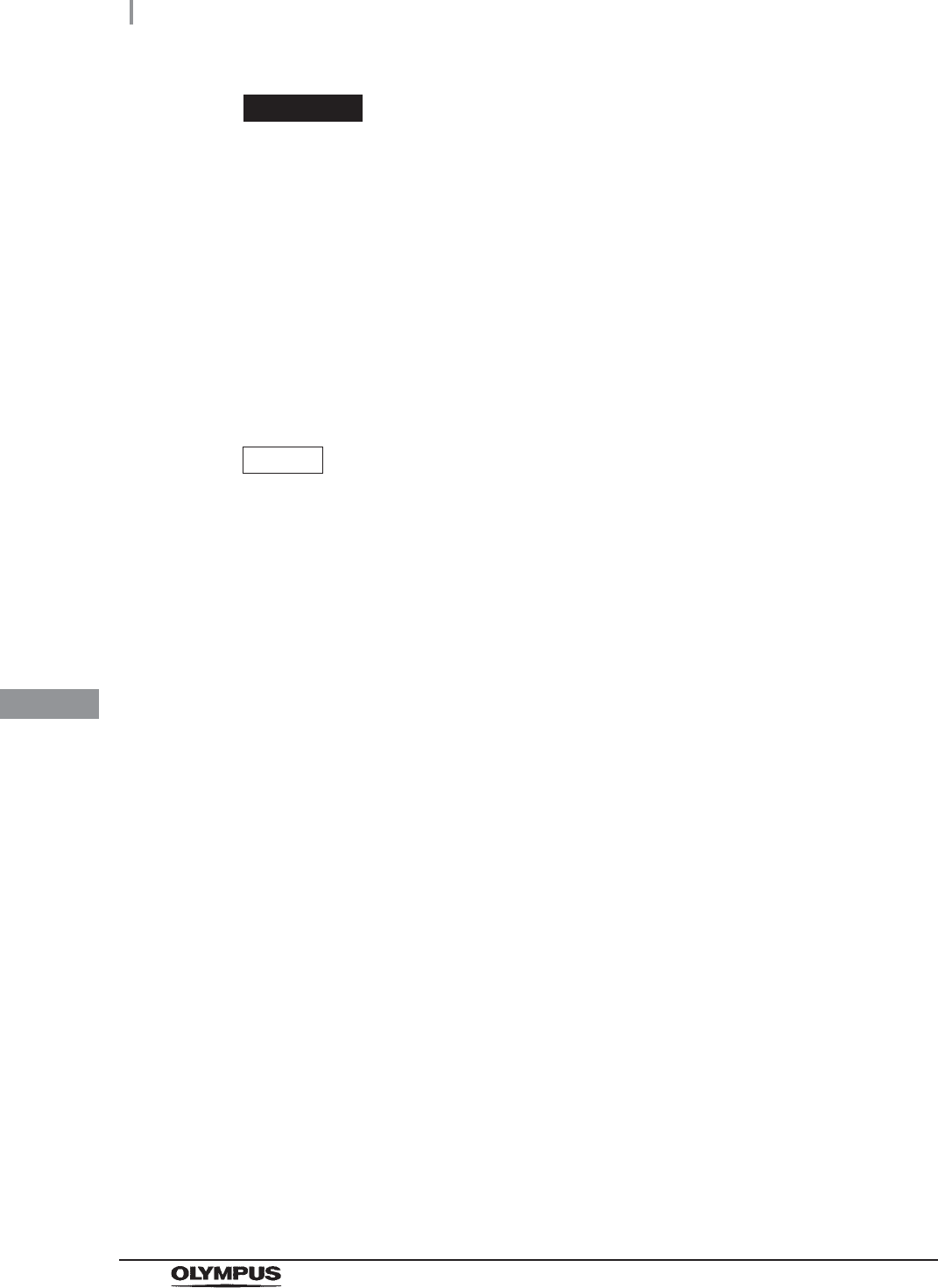
376
8.4 Replacing the water filter (MAJ-824 or MAJ-2318)
OER-Elite OPERATION MANUAL
Ch.8
CAUTION
• Hold the water filter wrench at a point below the projection on the grip. If you hold it
at a point closer to the water filter housing connector than the projection, you might
catch your finger in the reprocessor.
• If air gets in the water filter housing, it may extend the process time. In case of an
irregularity such as extension of the process time or lack of water supply, drain the
air as described in “Draining air in the water filter housing” on page 389.
• Do not to drop the removed water filter housing to avoid damaging the connector
below the water filter housing. Make sure that the O-ring at the head of the water
filter housing is free of irregularities such as cracks, breaks, rips, scratches, or
stains. Water leakage may result if the O-ring is not attached or is abnormal.
NOTE
• When replacing water filter, select the “Replace water filter” in the Replacement of
Consumable Items screen. Otherwise, the record of the replacement of the water
filter will not be created.
• Filter life varies depending on a number of factors including incoming water quality
and use volume.
• Using at least a prefilter (0.45 micron or less) can extend the life of the water filter.
If the prefilter is properly installed, the water filter and the prefilter should be
replaced at least once every 6 months. For information on the water pre-filtration
system, contact Olympus.
• After disinfection of the water supply piping, the quantity and/or concentration of the
disinfectant solution might be reduced, which prevents additional reprocessing
cycles from being performed. Do not add fresh disinfectant solution to the used
disinfectant solution. Except for the case of performing water line disinfection with
fresh new disinfectant solution, do not add fresh disinfectant solution to increase
the volume of the disinfectant solution in the OER-Elite. Drain the disinfectant
solution completely and replace with fresh disinfectant solution after disinfection of
the water supply piping. It is recommended to perform disinfection of the water
supply piping immediately before routine replacement of the disinfectant solution.
• Disinfecting the water supply piping also disinfects the water filter and other
components in the piping.
8.4 Replacing the water filter (MAJ-824 or MAJ-2318)
377
OER-Elite OPERATION MANUAL
Ch.8
Replacing the water filter workflow (when performing the
water line disinfection followed by the replacement of the
water filter)
See the replacement of the water filter workflow below.
Required items
Table 8 . 6
NOTE
• The test strip and water supply piping disinfection hose are required only when the
water line disinfection is performed after the water filter replacement.
• For the test strip, refer to Section 2.8, “Consumable accessories (Optional)”.
1MRC check, check result input.
on page 378
2Replacing the water filter.
on page 380
3Disinfecting the water line.
on page 392
Check Required items
FDA-cleared chemical indicator (test strip)
Water filter (MAJ-824 or MAJ-2318)
Water filter wrench
Water filter tubes (u 2)
Container with 2 L or larger capacity (wide-mouthed container such as a vat)
Water supply piping disinfection hose
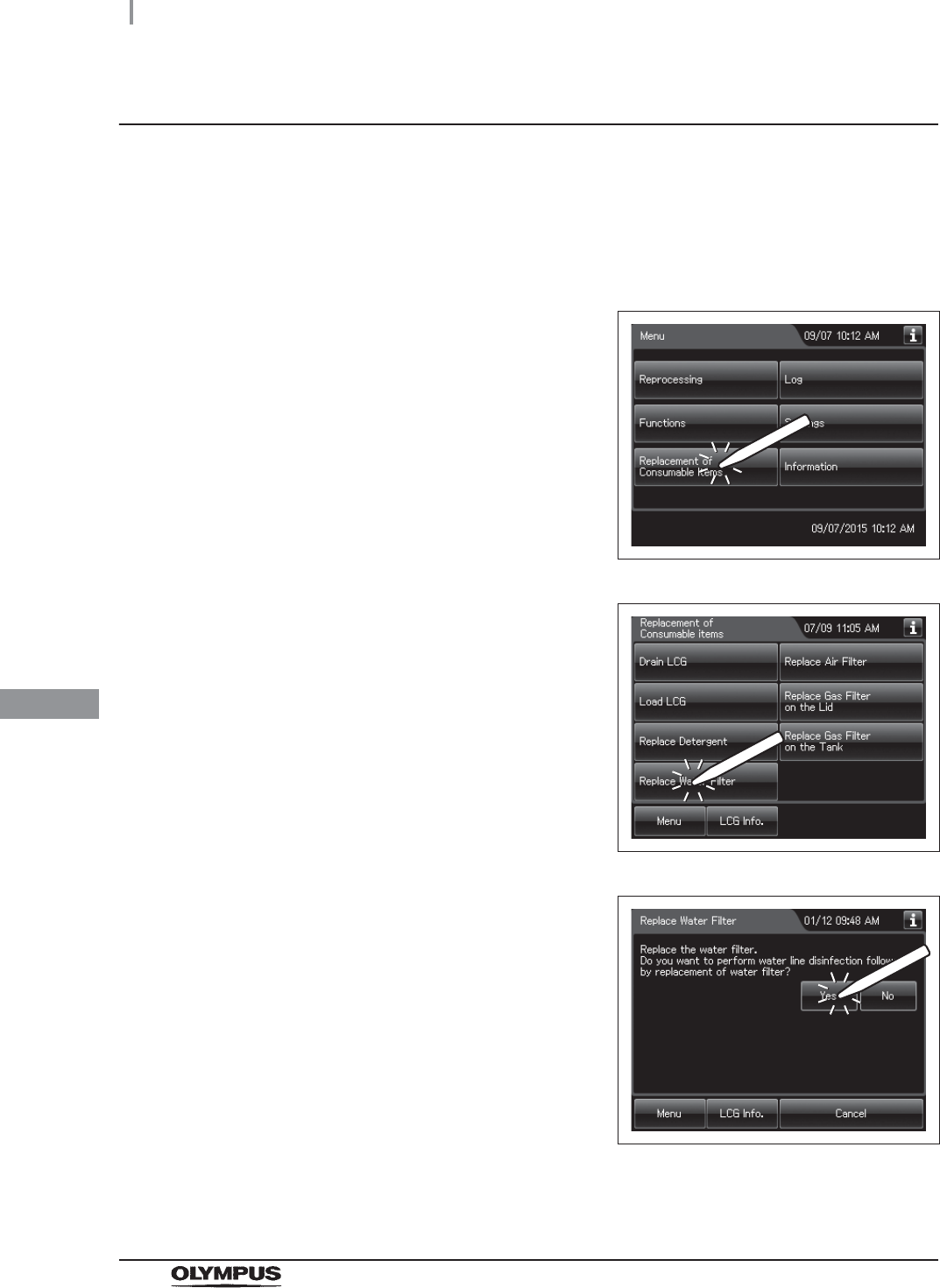
378
8.4 Replacing the water filter (MAJ-824 or MAJ-2318)
OER-Elite OPERATION MANUAL
Ch.8
MRC check, check result input
Before proceeding to the water line disinfection, always be sure to check using a test strip that the
concentration of the disinfectant solution is no less than the minimum recommended concentration.
For the MRC check, refer to Section 3.7, “Checking the MRC level and entering the check result”. The
disinfectant should be replaced when the concentration falls below the minimum recommended
concentration or the shelf life of the disinfectant has expired.
1Press the “Replacement of Consumable Items”
button on the Menu screen.
Figure 8.60
2Press the “Replace Water Filter” button on the
Replacement of Consumable Items menu.
Figure 8.61
3Press the “YES” button.
Figure 8.62
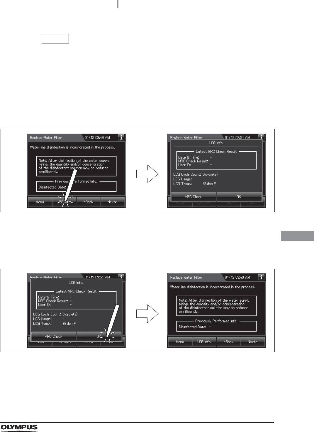
8.4 Replacing the water filter (MAJ-824 or MAJ-2318)
379
OER-Elite OPERATION MANUAL
Ch.8
NOTE
If water lines are not to be disinfected immediately after the water filter
replacement, press “No” and go to “Replacing the water filter” on page 380.
However, the water line disinfection must be executed even if it is not immediately
after the water filter replacement. Refer to Section 7.7, “Water line disinfection”.
4Press the “Next” button repeatedly until the touch screen display changes as shown
below.
5Press the “LCG Info.” button to display the LCG Info screen.
Figure 8.63
6Check the concentration of the disinfectant solution with the test strip, and entering
the result of the concentration of the disinfectant solution as described in Section 3.7,
“Checking the MRC level and entering the check result”.
7Press the “OK” button to close the LCG Info screen.
Figure 8.64
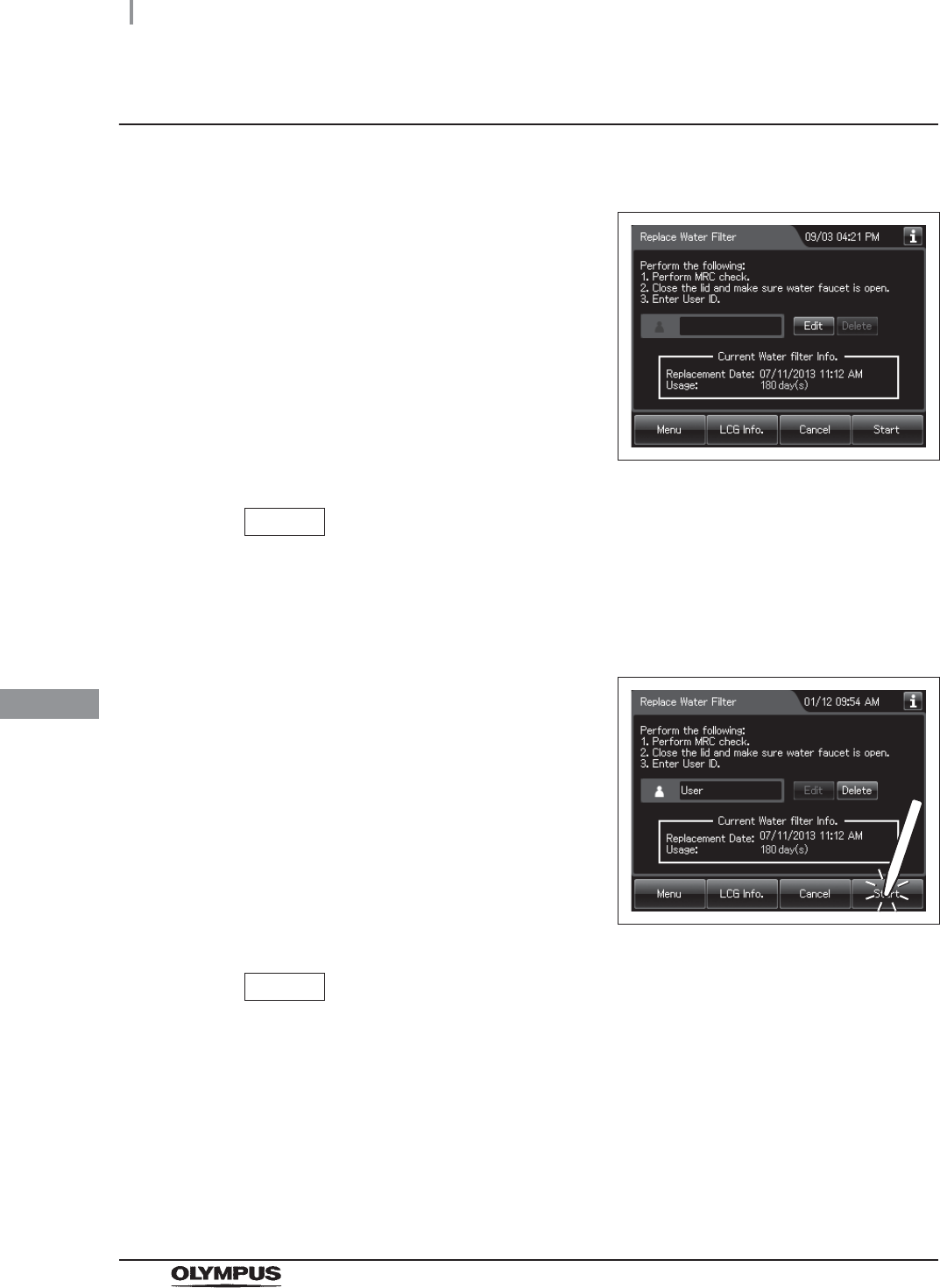
380
8.4 Replacing the water filter (MAJ-824 or MAJ-2318)
OER-Elite OPERATION MANUAL
Ch.8
Replacing the water filter
1Close the lid by pushing it until it clicks.
2Input the operator's user ID. For the detailed
procedures, refer to Section 3.6, “Entering ID”
(If applicable).
Figure 8.65
NOTE
• The input of the user ID can be omitted by modifying the user ID input setting. For
details, refer to Section 4.5, “User ID Setting”.
• If the “Delete” button is pressed, the entered ID can be deleted.
3Press the “Next” or “Start” button.
Figure 8.66
NOTE
When the lot number management of the water filter is activated, the lot number of
the water filter is entered after Step 3. For details, refer to “When entering the lot
number of the water filter” on page 400.
4Open the Front door. Place a container with a capacity of 2 L or more in front of the
reprocessor.
5Put the tube-side ends of the two filter tubes in the container placed above.
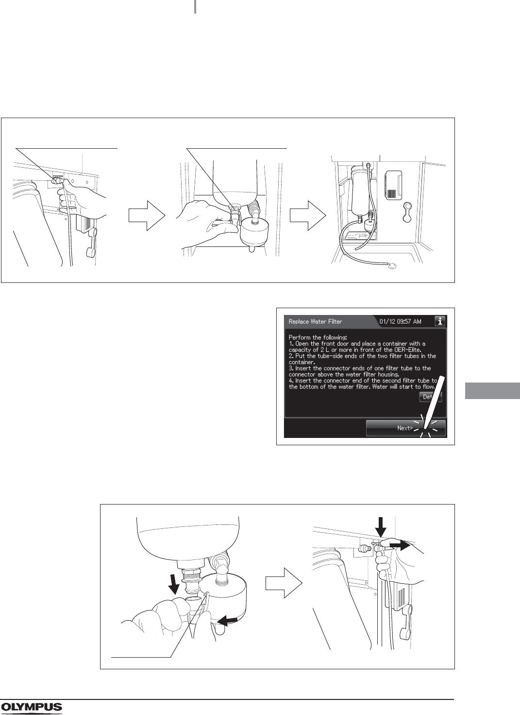
8.4 Replacing the water filter (MAJ-824 or MAJ-2318)
381
OER-Elite OPERATION MANUAL
Ch.8
6Insert the connector ends of the two filter tubes into the connector above the water
filter housing and the connector below the water filter housing until they click. Water
will start to flow from the tube connected to the connector below the water filter
housing.
Figure 8.67
7Press the “Next” button.
Figure 8.68
8When the water flow stops, disconnect the two filter tubes by pushing the lock levers
on their connectors.
Figure 8.69
Connector below water
filter housing
Connector above water
filter housing
Lock lever
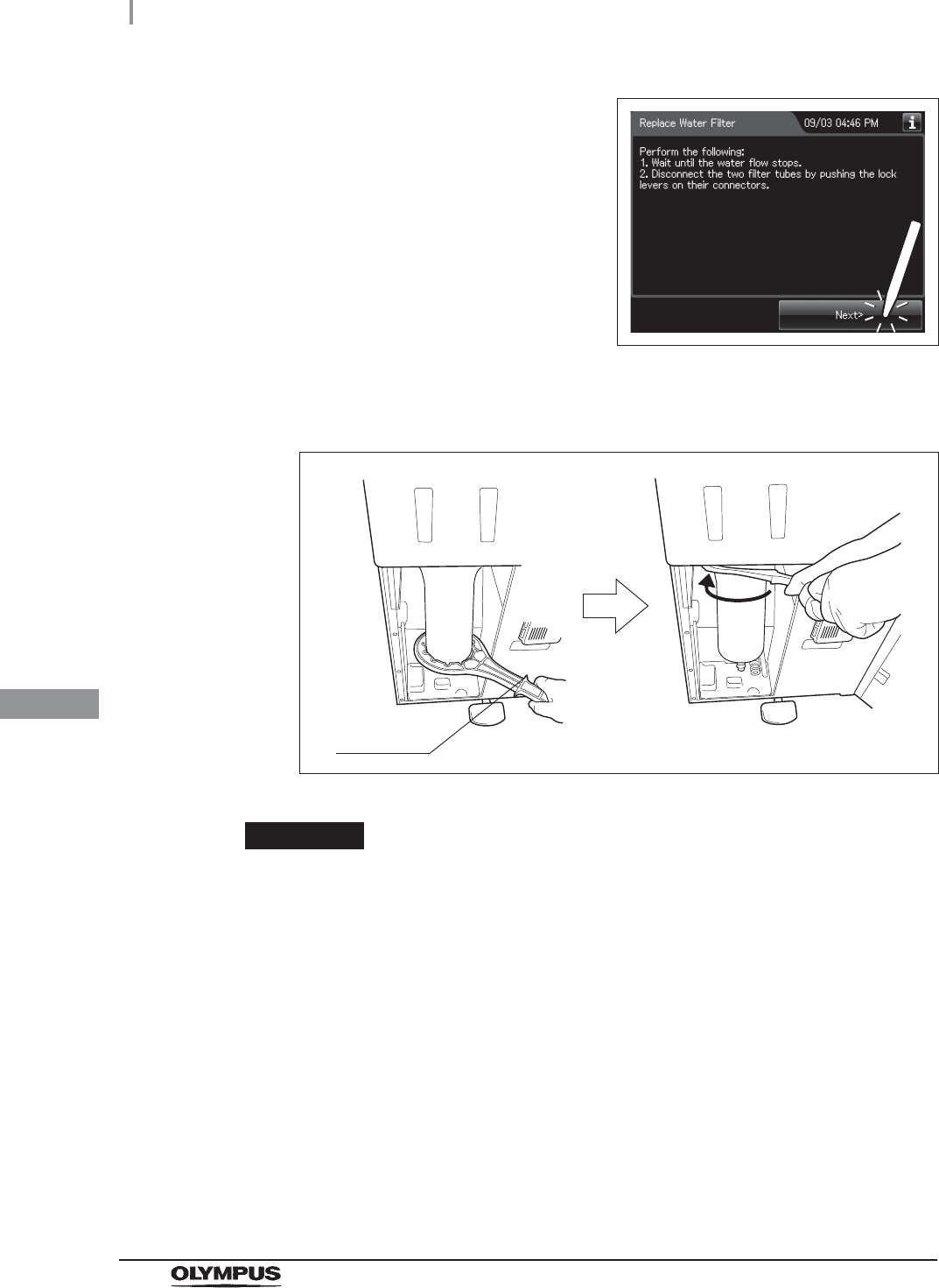
382
8.4 Replacing the water filter (MAJ-824 or MAJ-2318)
OER-Elite OPERATION MANUAL
Ch.8
9Press the “Next” button.
Figure 8.70
10 Insert the water filter wrench from below the water case and rotate the tool as shown
below to loosen the water filter housing.
Figure 8.71
CAUTION
Hold the water filter wrench at a point closer to you than to the projection on the
grip. If you hold it at a point closer to the water filter housing connector than the
projection, you might catch your finger in the mechanism.
Projection
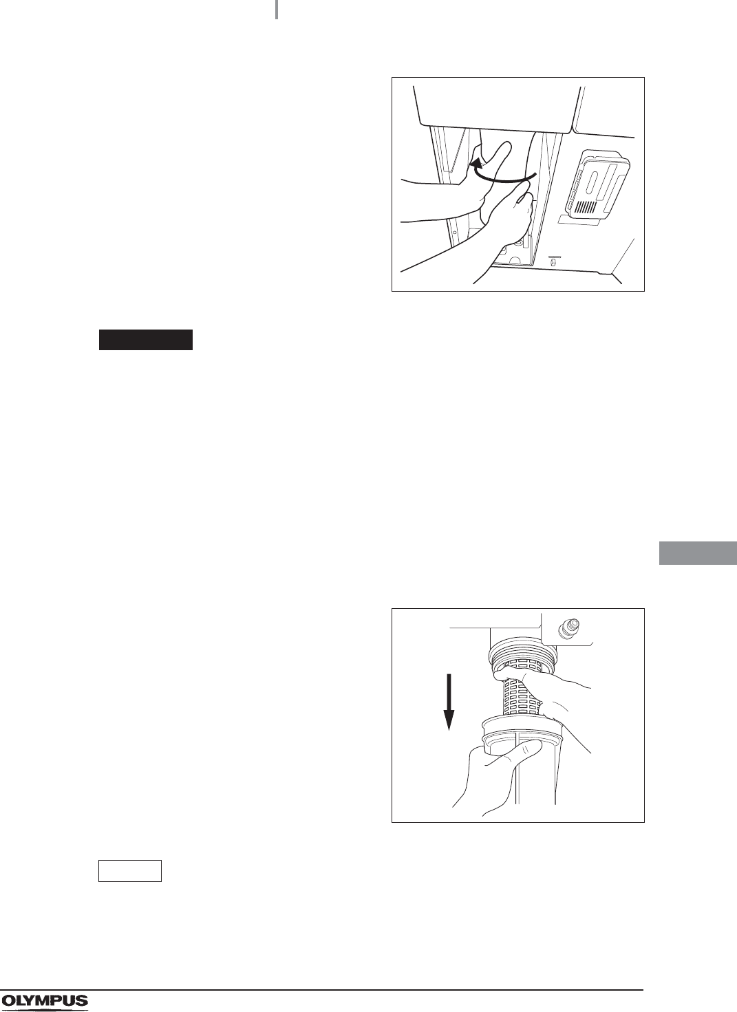
8.4 Replacing the water filter (MAJ-824 or MAJ-2318)
383
OER-Elite OPERATION MANUAL
Ch.8
11 Hold the water filter housing with both hands
and rotate it in the direction shown to remove it.
Figure 8.72
CAUTION
• Once the water filter housing has been fully loosened, hold it with both hands and
remove it. If the case is not fully loosened, your hands may slip and you could be
injured.
• When the water filter is removed, residual water flows from the connectors.
Therefore, you should cover the water filter with the water filter housing when
removing so that the residual water is caught in the case. If the water tray fills with
residual water, remove the water tray and drain it.
• Do not to drop the removed water filter housing to avoid damaging the water
housing. Water leakage may result if the water filter housing is cracked, broken, or
otherwise damaged.
12 Pull both the water filter housing and the old
water filter downward to remove.
Figure 8.73
NOTE
When the reprocessor is shipped from the factory, the water filter is not mounted in
the water filter housing.
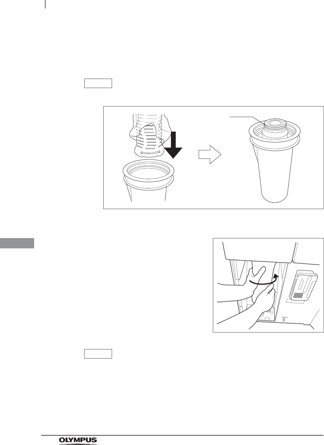
384
8.4 Replacing the water filter (MAJ-824 or MAJ-2318)
OER-Elite OPERATION MANUAL
Ch.8
13 Open the bottom (the side without the O-ring) of the package containing the new
water filter.
14 Place the new water filter directly from the bag into the water filter housing so that
O-ring will be positioned upward.
NOTE
Do not touch the inner side of the water filter or allow dust to get in it.
Figure 8.74
15 Rotate the water filter housing in the direction
shown.
Figure 8.75
NOTE
• To ensure smooth loading, it is recommended to moisten the O-ring at the head of
the water filter with clean water or 70% ethyl alcohol or 70% isopropyl alcohol
before securing it temporarily.
• The rotation drag increases during temporary securing, but rotate the case all the
way until it is stopped.
O-ring
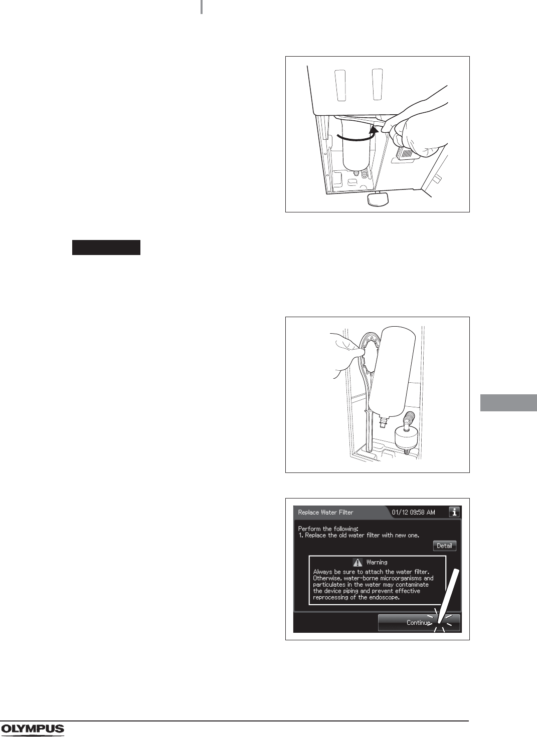
8.4 Replacing the water filter (MAJ-824 or MAJ-2318)
385
OER-Elite OPERATION MANUAL
Ch.8
16 Attach the water filter wrench and rotate it
slowly in the direction shown to tighten.
Figure 8.76
CAUTION
Tighten the water filter case securely. Insecure tightening may lead to a risk of
water leak.
17 Remove the water filter wrench and place it in
the space on the left of the water filter housing.
Figure 8.77
18 Press the “Continue” button.
Figure 8.78
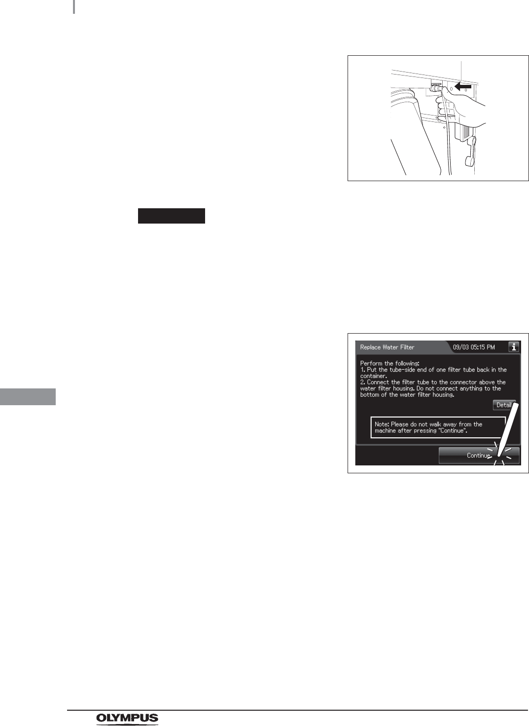
386
8.4 Replacing the water filter (MAJ-824 or MAJ-2318)
OER-Elite OPERATION MANUAL
Ch.8
19 Put the tube-side end of the filter tube in the
container, and insert the connector end of the
filter tube into the connector above the water
filter housing until it clicks. Do not connect
anything to the connector bottom of the water
filter housing.
Figure 8.79
CAUTION
Be sure to drain air from the newly attached water filter. If air gets in the water filter
housing, the process time may be extended. Air should also be drained from the
water filter housing whenever there is an irregularity such as extension of the
process time.
20 Make sure that the water faucet is open.
21 Press the “Continue” button.
Figure 8.80
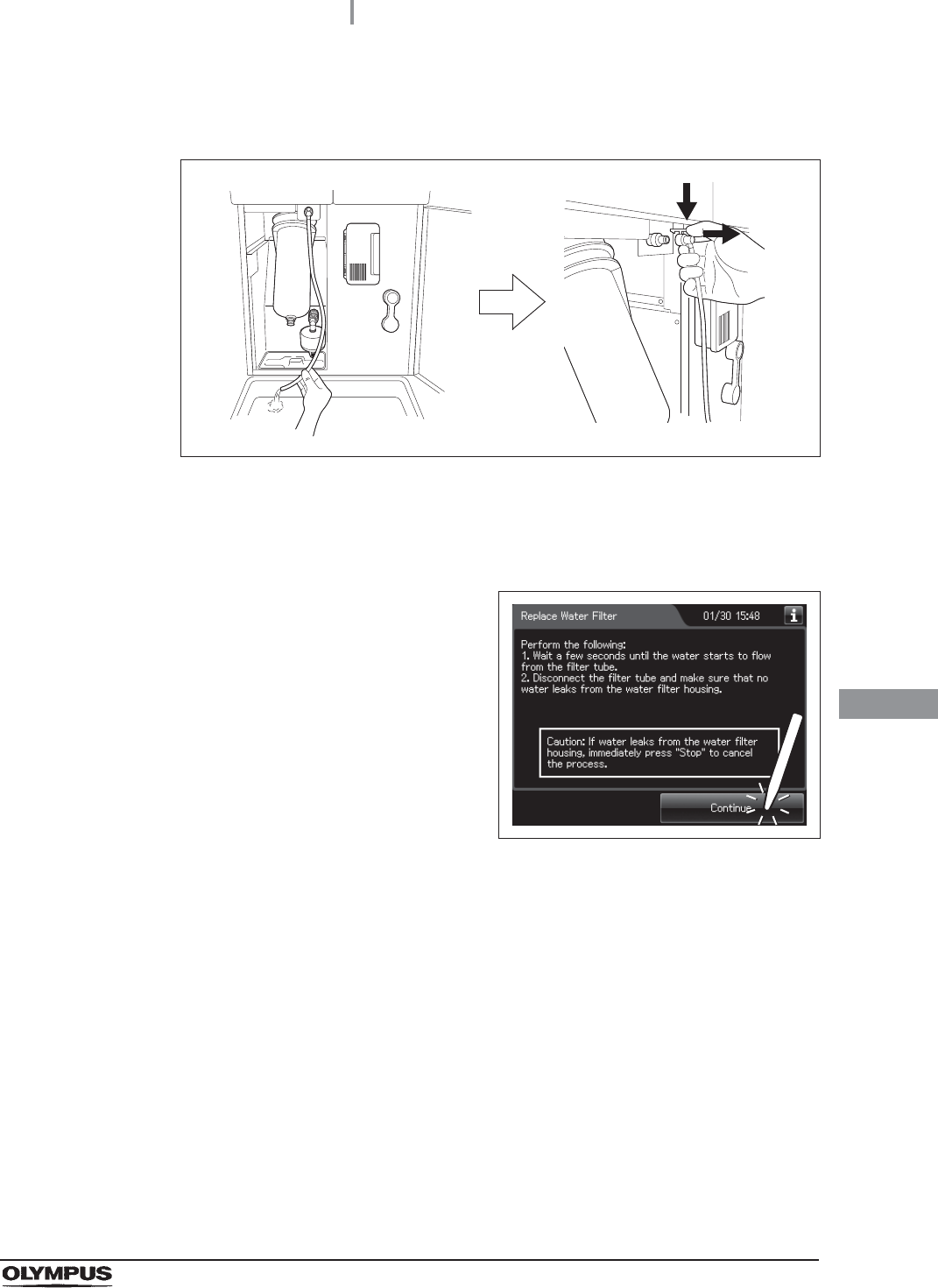
8.4 Replacing the water filter (MAJ-824 or MAJ-2318)
387
OER-Elite OPERATION MANUAL
Ch.8
22 When water starts to flow continuously from the filter tube, disconnect the tube by
pushing its lock lever. Water flow should stop when the filter tube is disconnected.
Figure 8.81
23 Make sure that no water leaks from the water filter housing. If no water leaks, press
the “Continue” button. If a water leak is observed, immediately press the “STOP”
button to stop water supply and reinstall the water filter.
24 Press the “Continue” button.
Figure 8.82
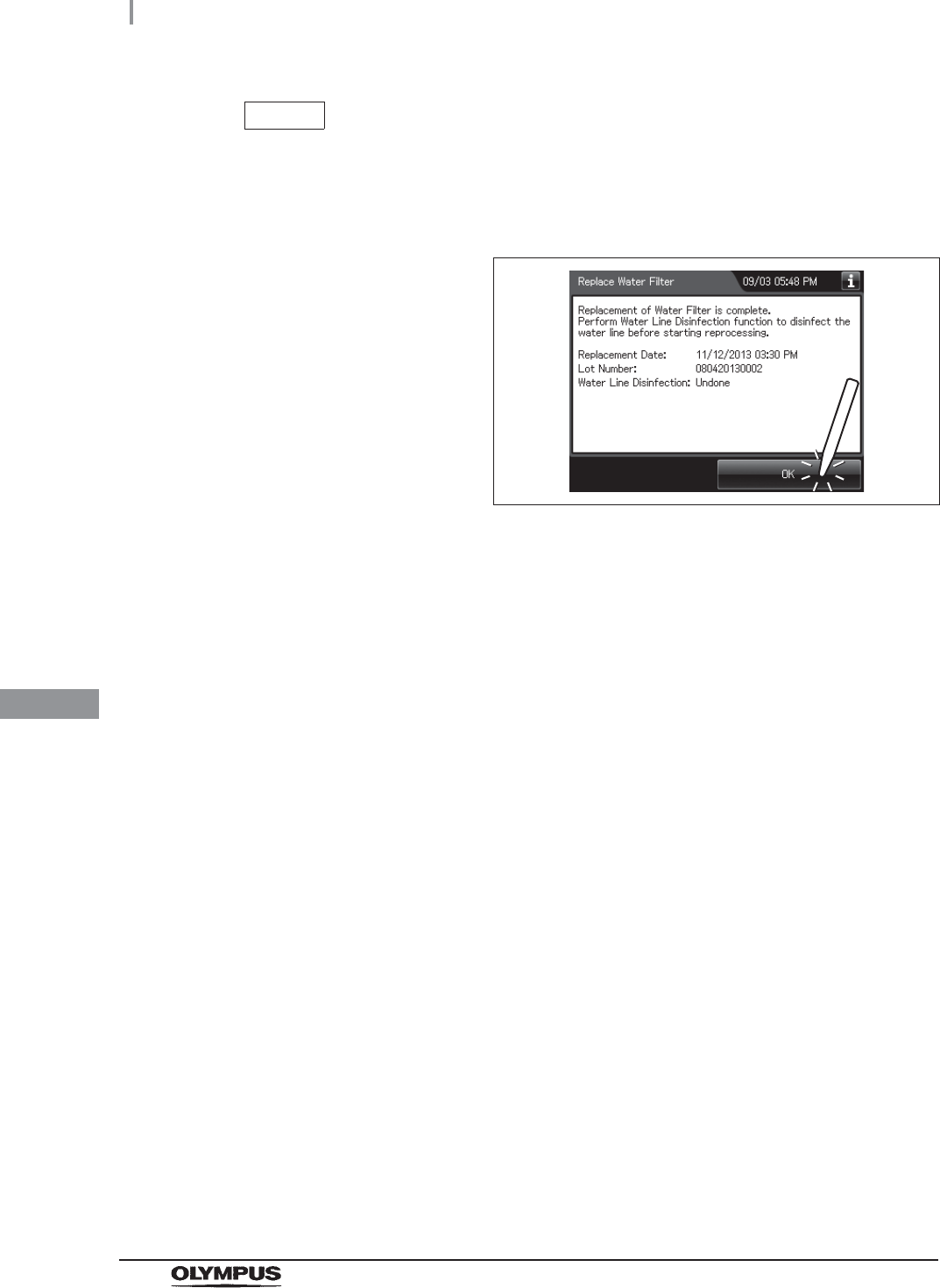
388
8.4 Replacing the water filter (MAJ-824 or MAJ-2318)
OER-Elite OPERATION MANUAL
Ch.8
NOTE
When disinfecting the water line later is not selected, the following screen is
displayed. Close the front door, Rinse the filter tubes with running water, dry it
completely and store in a clean place to complete the water filter replacement
procedure. In this case, the water lines should be disinfected later.
Figure 8.83
25 Press “OK” button to finish.
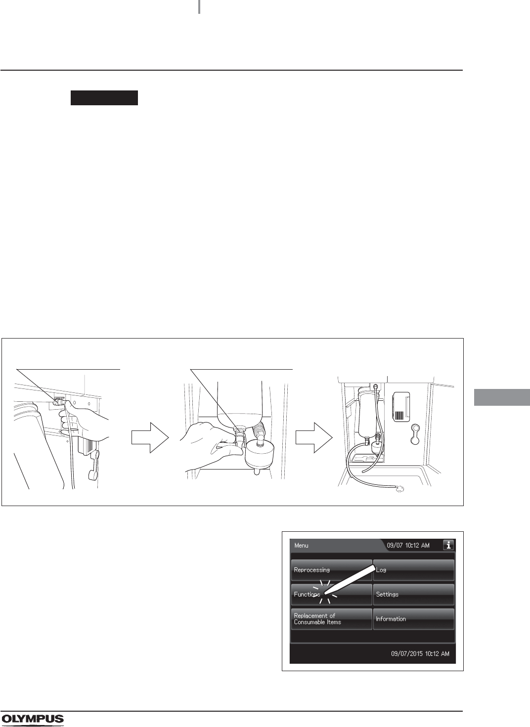
8.4 Replacing the water filter (MAJ-824 or MAJ-2318)
389
OER-Elite OPERATION MANUAL
Ch.8
Draining air in the water filter housing
CAUTION
Be sure to drain air from the newly attached water filter. If air gets in the water filter
housing, the process time may be extended. Air should also be drained from the
water filter housing whenever there is an irregularity such as extension of the
process time.
1Close the lid by pushing it until it clicks.
2Open the Front door. Place a container with a capacity of 2 L or more in front of the
reprocessor.
3Put the tube-side ends of the two filter tubes in the container placed above.
4Insert the connector ends of the two filter tubes into the connector above the water
filter housing and the connector below the water filter housing until they click. Water
will start to flow from the tube connected to the connector below the water filter
housing.
Figure 8.84
5Press the “Functions” button on the Menu
screen.
Figure 8.85
Connector below water
filter housing
Connector above water
filter housing
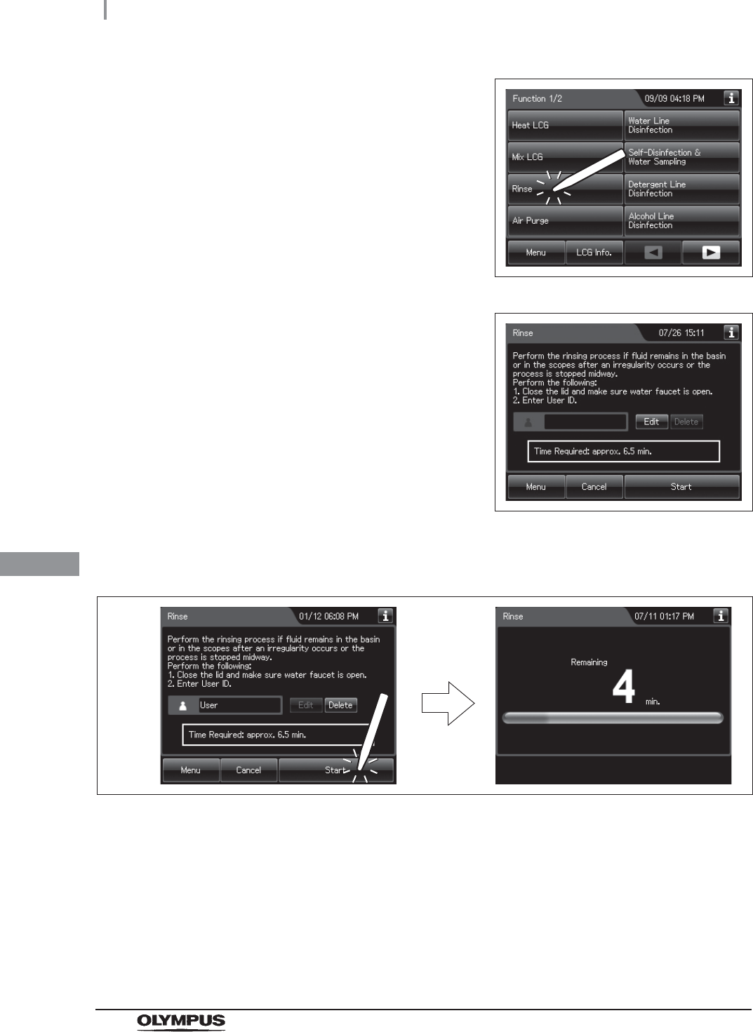
390
8.4 Replacing the water filter (MAJ-824 or MAJ-2318)
OER-Elite OPERATION MANUAL
Ch.8
6Press the “Rinse” button on the Function menu.
Figure 8.86
7Input the operator's user ID. For the detailed
procedures, refer to Section 3.6, “Entering ID”
(If applicable).
Figure 8.87
8Press the “Start” button. Rinse starts and the touch screen displays the remaining
time, which will count down every minute.
Figure 8.88
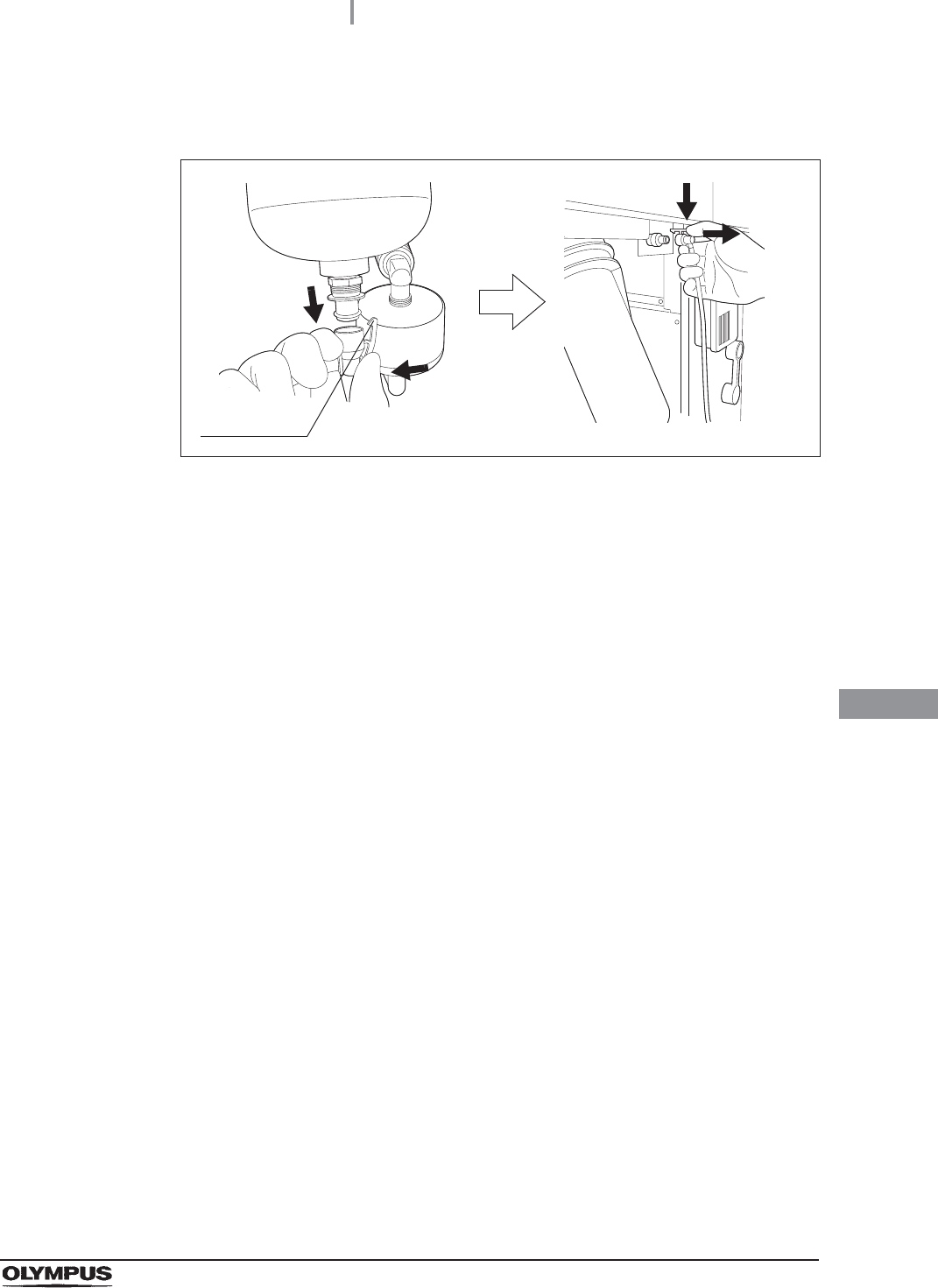
8.4 Replacing the water filter (MAJ-824 or MAJ-2318)
391
OER-Elite OPERATION MANUAL
Ch.8
9When water starts to flow continuously from the filter tube, disconnect the tube by
pushing its lock lever. Water flow should stop when the filter tube is disconnected.
Figure 8.89
10 Press the “STOP” button to drain water from the reprocessing basin.
11 Close the front door.
12 Rinse the filter tube with running water, dry it completely and store in a clean place.
Lock lever
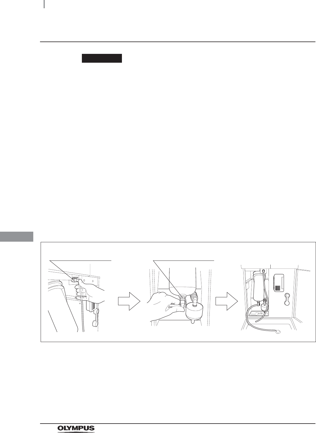
392
8.4 Replacing the water filter (MAJ-824 or MAJ-2318)
OER-Elite OPERATION MANUAL
Ch.8
Disinfecting the water line
WARNING
• Before disinfecting the water supply piping, check the concentration of the
disinfectant solution with the test strip, and replace the disinfectant solution if the
disinfectant concentration is below the required level. If this check is not performed,
disinfection may be insufficient.
• Disinfection of the water supply piping is required each time the water filter is
replaced (i.e., at least once a month). There may be other circumstances where
this is required, for example a flood or hurricane. Microbiological sampling of the
OER-Elite rinse water may indicate disinfection is required.
• Disconnect the connecting tubes from the connectors on the reprocessor before
disinfecting the water supply piping. Otherwise, a jet of disinfectant solution may be
output from the connecting tubes and leak from a connector such as the gas filter
case connector.
1Place as container with a capacity of 2 L or more in front of the reprocessor.
2Put the tube-side ends of the two filter tubes in the container placed and insert the
connector ends of the two filter tubes into the connector above the water filter housing
and the connector below the water filter housing until they click. Water will start to flow
from the tube connected to the connector below the water filter housing.
Figure 8.90
Connector below water
filter housing
Connector above water
filter housing
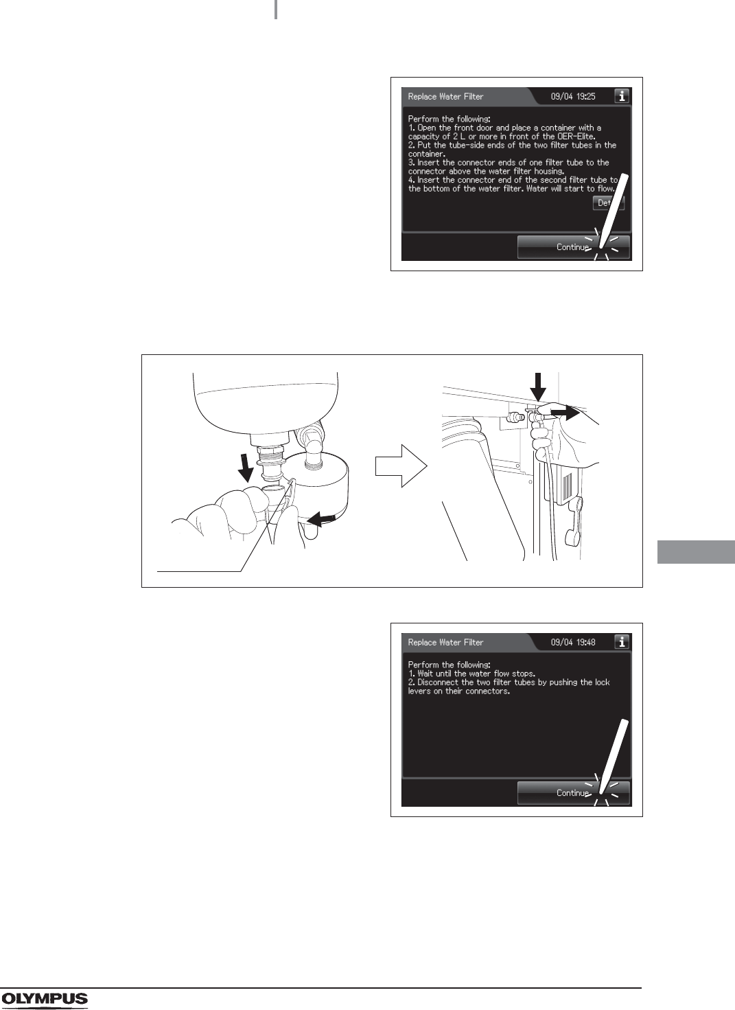
8.4 Replacing the water filter (MAJ-824 or MAJ-2318)
393
OER-Elite OPERATION MANUAL
Ch.8
3Press the “Continue” button.
Figure 8.91
4When water flow stops, disconnect the two filter tubes by pushing the lock levers on
their connectors.
Figure 8.92
5Press the “Continue” button.
Figure 8.93
6Step on the foot pedal to open the lid.
Lock lever
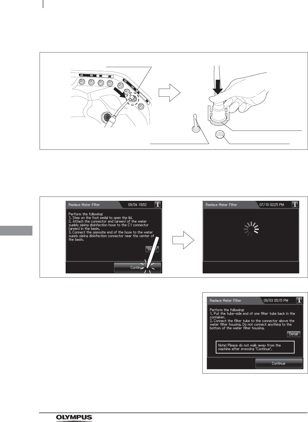
394
8.4 Replacing the water filter (MAJ-824 or MAJ-2318)
OER-Elite OPERATION MANUAL
Ch.8
7Connect the water supply piping disinfection hose between the connector C1 in the
reprocessing basin and the water supply piping disinfection connector.
Figure 8.94
8Close the lid by pushing until it clicks.
9Press the “Continue” button to supply the disinfectant solution in the reprocessing
basin.
Figure 8.95
10 When the reprocessing basin is filled with
disinfectant solution, a buzzer sounds three
times and the touch screen displays the follow
screen.
Figure 8.96
11 Put the tube-side end of the filter tube and put it in the container.
Washing case mount
Temperature sensor
Connector C1
Water supply piping
disinfection connector
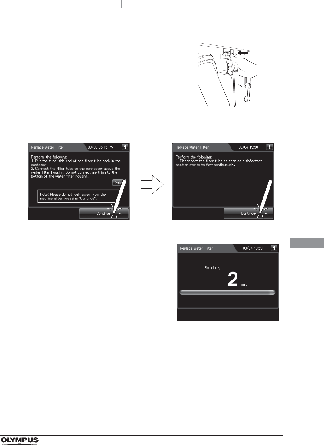
8.4 Replacing the water filter (MAJ-824 or MAJ-2318)
395
OER-Elite OPERATION MANUAL
Ch.8
12 Insert the connector end of the filter tube into
the connector above the water filter housing
until it clicks. Do not connect anything to the
connector below the water filter housing.
Figure 8.97
13 Press the “Continue” button twice.
Figure 8.98
14 When the disinfection process starts, the touch
screen displays the remaining time and the
progress bar.
Figure 8.99
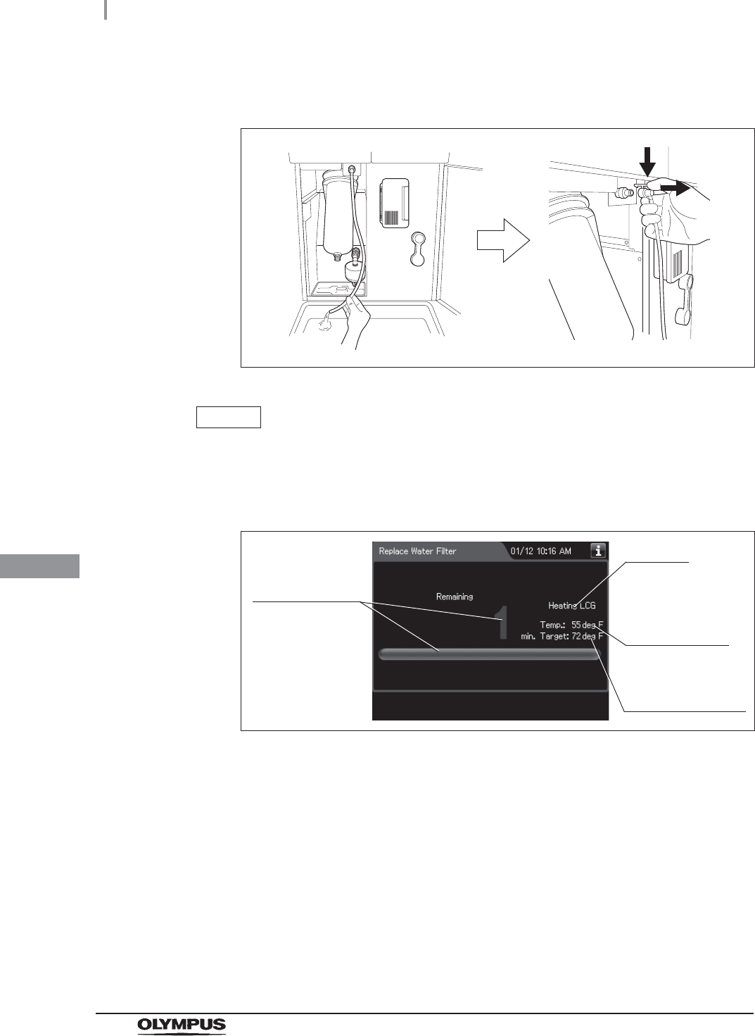
396
8.4 Replacing the water filter (MAJ-824 or MAJ-2318)
OER-Elite OPERATION MANUAL
Ch.8
15 When water starts to flow continuously from the filter tube, disconnect the tube by
pushing its lock lever. Water flow should stop when the filter tube is disconnected.
Figure 8.100
NOTE
If the temperature of the disinfectant solution is less than 20qC (68qF), it will be
heated to 20qC (68qF). During heating, the remaining time countdown and the
progress bar display stop and turn gray. After the completion of heating, the
remaining time countdown and progress bar display resume.
Figure 8.101
Progress stops
and turns gray.
It blinks
Current
temperature of
the disinfectant
solution
Target temperature
of the disinfectant
solution
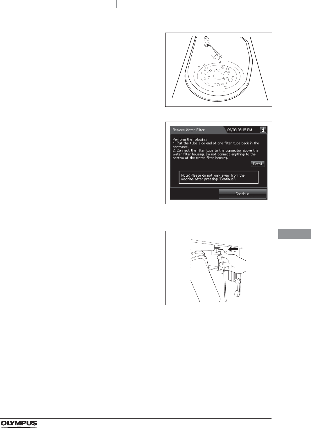
8.4 Replacing the water filter (MAJ-824 or MAJ-2318)
397
OER-Elite OPERATION MANUAL
Ch.8
16 Make sure that a jet of fluid is output from the
water supply/circulation nozzle to the dome of
lid during the process.
Figure 8.102
17 When the remaining time displayed on the
touch screen reaches 0 minute, the buzzer
sounds and the touch screen displays the
following screen.
Figure 8.103
18 Put the tube-side end of the filter tube back in the container.
19 Insert the connector end of the filter tube into
the connector above the water filter housing.
Do not connect a filter tube to the connector
below the water filter housing.
Figure 8.104
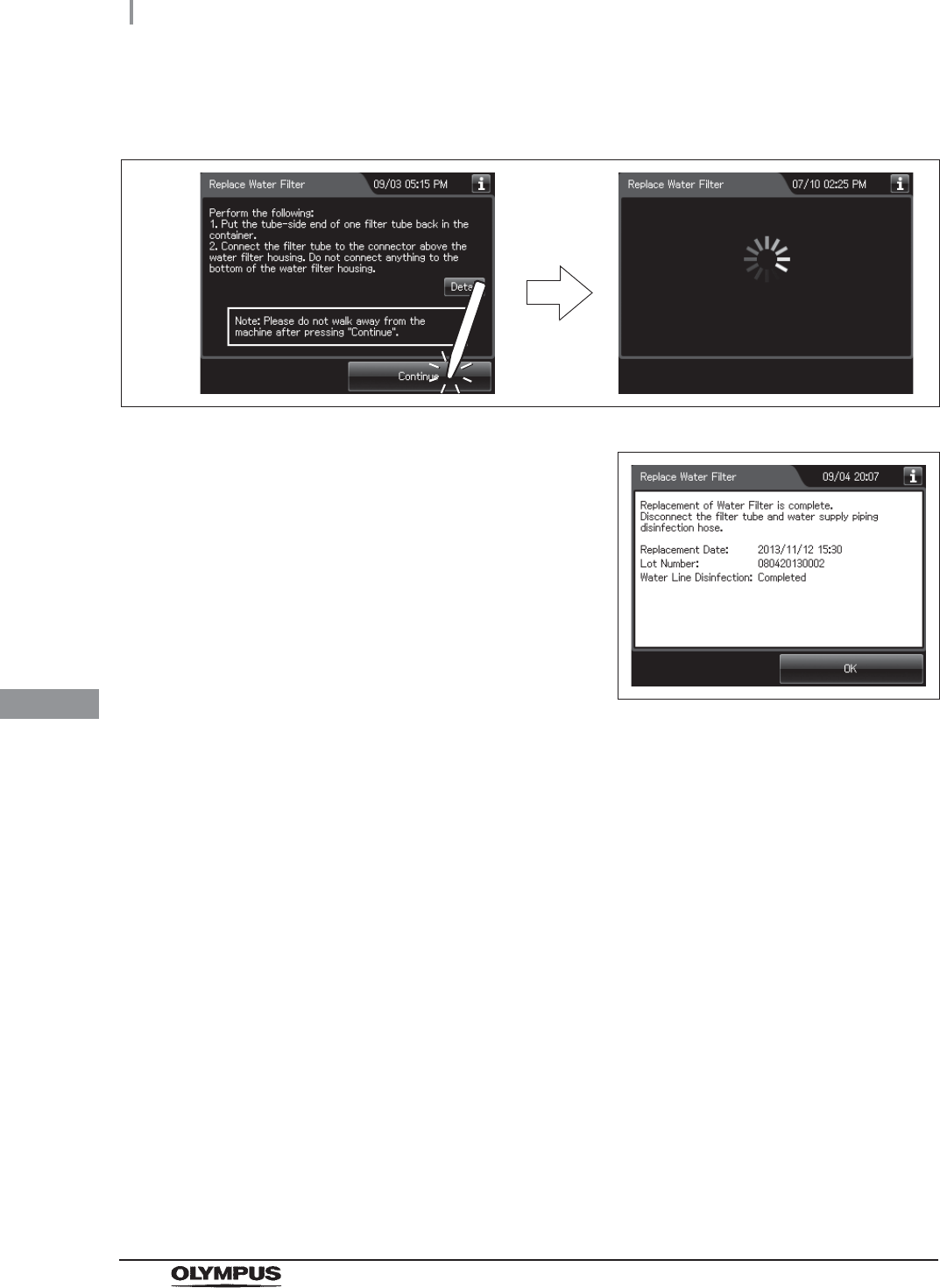
398
8.4 Replacing the water filter (MAJ-824 or MAJ-2318)
OER-Elite OPERATION MANUAL
Ch.8
20 Press the “Continue” button. The touch screen displays a screen as shown in the
following figure and water will flow from the filter tube.
Figure 8.105
21 After several seconds, the buzzer sounds
indicating the end of the process and the touch
screen displays the following screen.
Figure 8.106
22 Disconnect the filter tube by pushing its lock lever.
23 Close the front door.
24 Step on the foot pedal to open the lid.
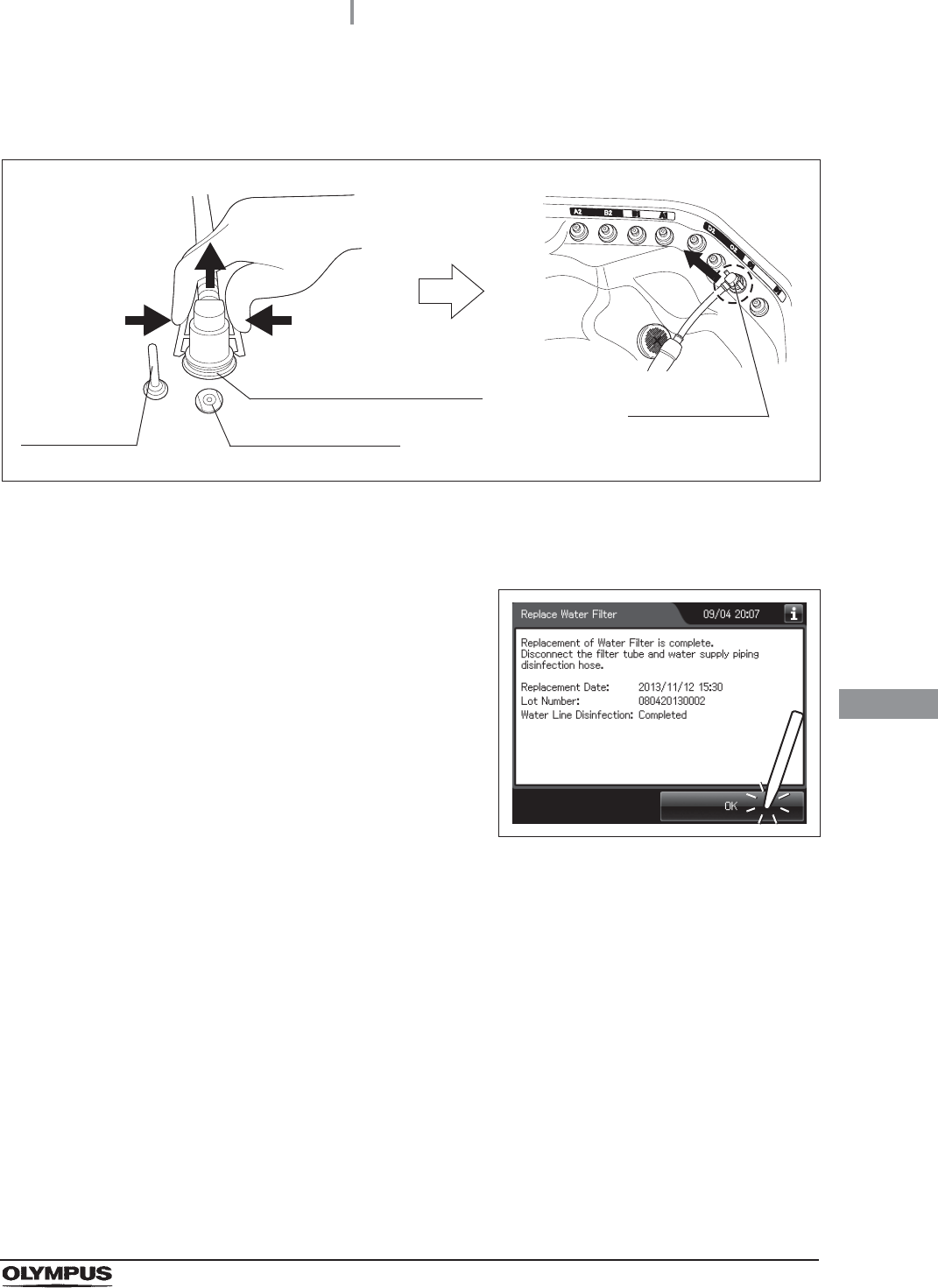
8.4 Replacing the water filter (MAJ-824 or MAJ-2318)
399
OER-Elite OPERATION MANUAL
Ch.8
25 Disconnect the water supply piping disinfection hose and close the by pushing until it
clicks.
Figure 8.107
26 Rinse the filter tube and water supply piping disinfection hose thoroughly in running
water, dry them thoroughly, and store in a clean place.
27 Press the “OK” button to complete the water
filter replacement process.
Figure 8.108
Water supply piping
disinfection hose connector
Washing case mount
Temperature
sensor
Connector C1
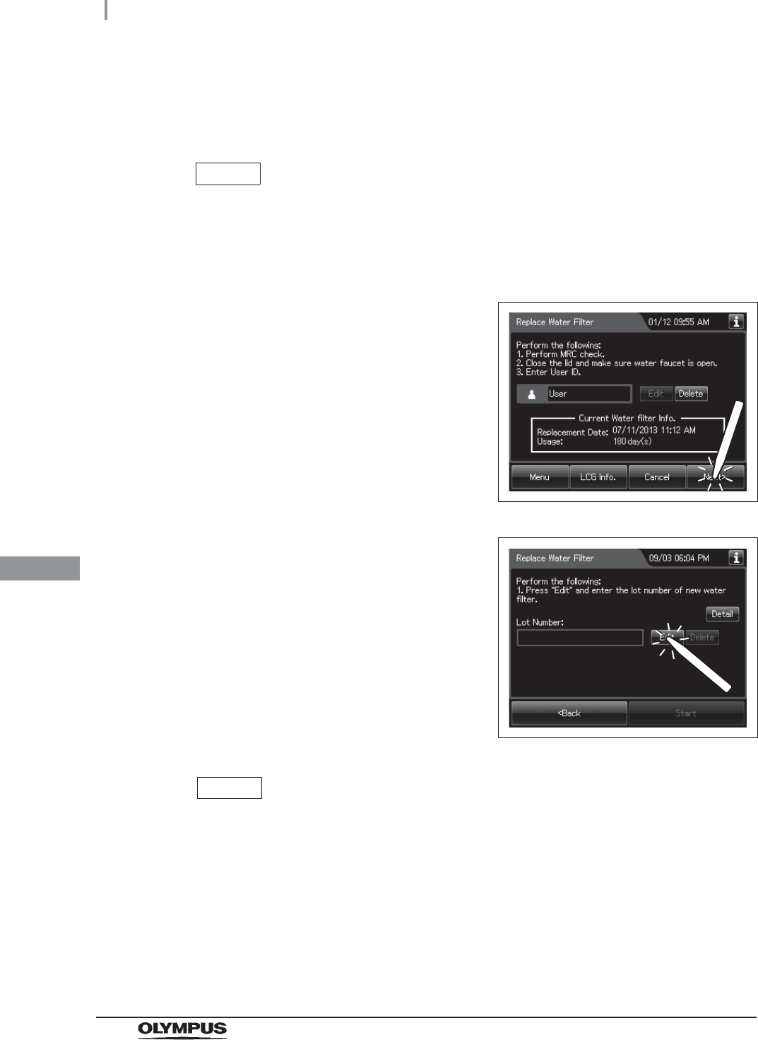
400
8.4 Replacing the water filter (MAJ-824 or MAJ-2318)
OER-Elite OPERATION MANUAL
Ch.8
When entering the lot number of the water filter
If the lot number management is activated, enter the lot number according to the following
procedure.
NOTE
• The lot number is printed on a label affixed to the box containing the water filter.
• The lot number of water filter can be recorded. For the setting change method, refer
to Section 4.15, “Filter lot number management”.
1If the filter lot number management of the water
filter is active, the touch screen displays a
screen as shown in following figure at Step 3 in
“Replacing the water filter” on page 380.
Press the “Next” button.
Figure 8.109
2Press the “Edit” button to display the lot entry
screen.
Figure 8.110
NOTE
If the “Delete” button is pressed, the entered lot number can be deleted.
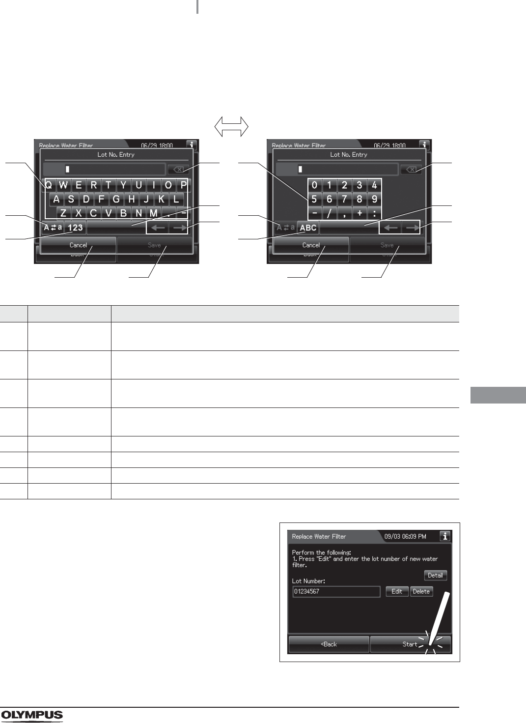
8.4 Replacing the water filter (MAJ-824 or MAJ-2318)
401
OER-Elite OPERATION MANUAL
Ch.8
3Enter the lot number of the new water filter by the software keyboard on the touch
screen and press the “Save” button.
No. Button Note
1 Alphabet/
Numeral key
Enter the alphabet or a numeral.
2 Uppercase/
Lowercase button
Press “Uppercase/lowercase” button to switch alphabet character on the soft keyboard
between uppercase characters and lowercase characters.
3 Numeric/
Alphabetic button
Press “Numeric or Alphabetic” button to switch the input mode between a numeral and
the alphabet.
4 Backspace button Press the “Backspace” button to delete the left character of a cursor.
When a cursor is on the left edge, this button turns gray and becomes unavailable.
5 Space button Press the “Space” button to insert a space character.
6 Cursor move button Press the cursor move button to move the cursor left or right.
7 Cancel button Return to the previous screen without saving the setting value.
8 Save button Return to the previous screen and save the entered value.
4Press the “Start” button. Go to Step 4 in
“Replacing the water filter” on page 380.
Figure 8.111
41
2
3
5
6
7 8
41
2
3
5
6
7 8
Alphabet input Numeral input
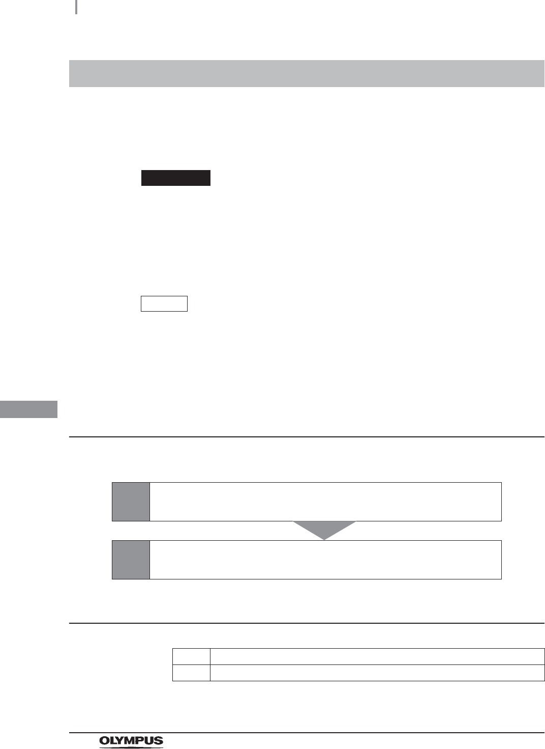
402
8.5 Replacing the air filter (MAJ-823)
OER-Elite OPERATION MANUAL
Ch.8
Replace the air filter every month.
To create the record of the replacement of the air filter, select “Replace Air Filter” in the Replacement of
Consumable Items menu.
WARNING
• Always be sure to attach the specified air filter. Otherwise, the air may contaminate
the reprocessor piping and/or the scope and prevent effective reprocessing.
• Replace the air filter at least every month. If the performance of the air filter drops,
insufficient elimination of miscellaneous bacteria in air may cause contamination of
the instrument and scopes and make the reprocessing insufficient.
NOTE
When the air filter counter setting is activated, the filter replacement indicator can
be displayed on the top right of the touch screen and on the “Replace Air Filter”
button on the Replacement of Consumable Items menu when the counter setting
value is reached.
Workflow of replacement of the air filter
See the replacement of air filter workflow below.
Required items
Table 8.7
8.5 Replacing the air filter (MAJ-823)
1Replacing the air filter.
on page 403
2Inspecting air leakage from the air filter connectors.
on page 408
Check Required items
Air filter (MAJ-823)
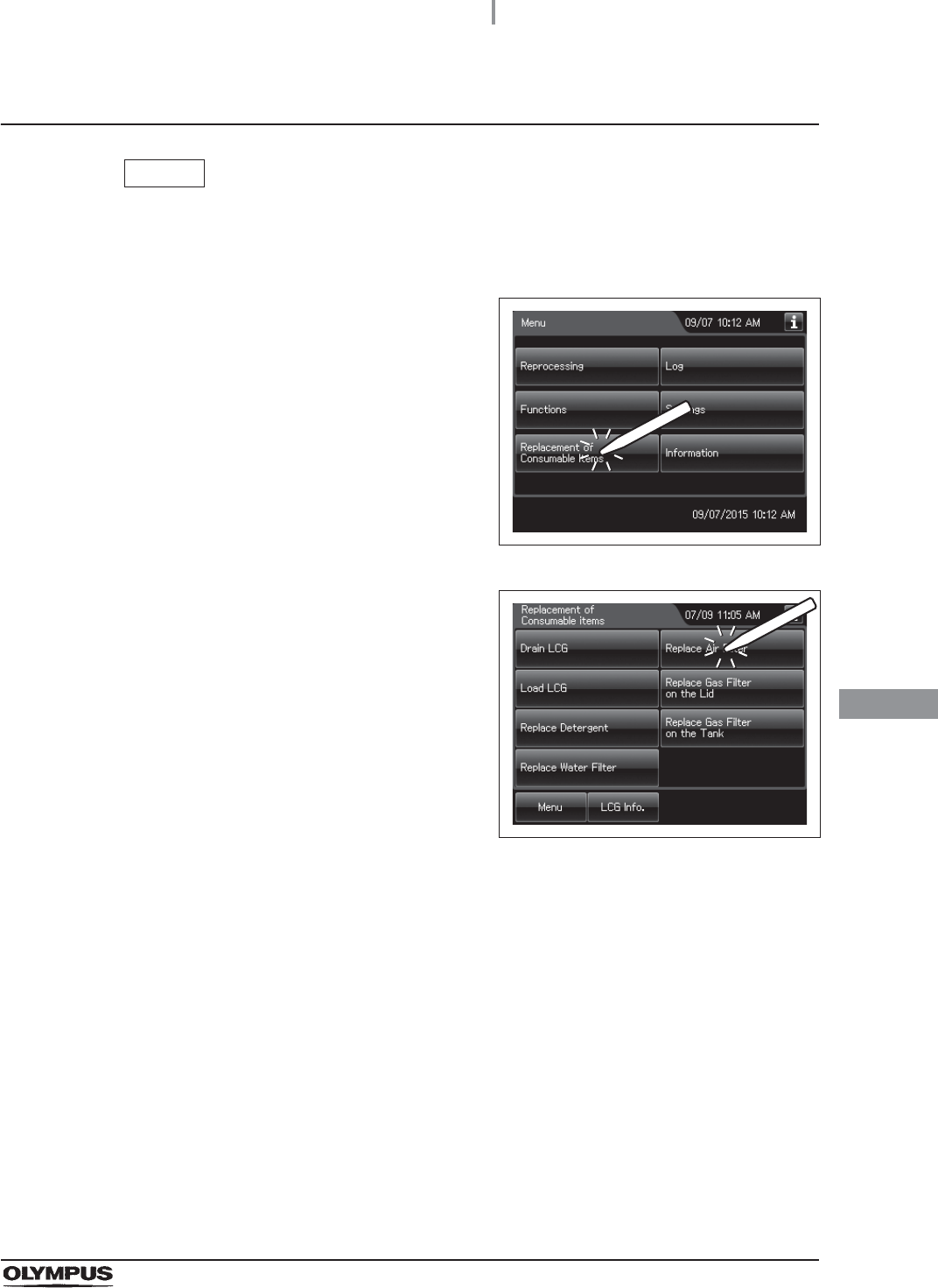
8.5 Replacing the air filter (MAJ-823)
403
OER-Elite OPERATION MANUAL
Ch.8
Replacing the air filter
NOTE
If you do not need to create the record of the replacement of the air filter, the
following operations of GUI can be skipped.
1Press the “Replacement of Consumable items”
button on the Menu screen.
Figure 8.112
2Press the “Replace Air Filter” button.
Figure 8.113
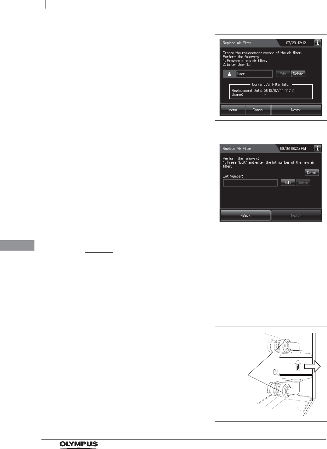
404
8.5 Replacing the air filter (MAJ-823)
OER-Elite OPERATION MANUAL
Ch.8
3Enter the operator's user ID. For the detailed
procedures, refer to Section 3.6, “Entering ID”
(If applicable). Then, press the “Edit” button to
display the lot entry screen.
Figure 8.114
Figure 8.115
NOTE
• The input of the user ID can be omitted by modifying the user ID input setting. For
details, refer to Section 4.5, “User ID Setting”.
• If the “Delete” button is pressed, the entered ID can be deleted.
• If the “Delete” button is pressed, the entered lot number can be deleted.
4Open the front door of the reprocessor.
5Remove the old air filter by pushing the sleeves
on the two connectors toward the device.
Figure 8.116
Sleeves