Olympus Medical Systems RU2020 Endoscope Reprocessor User Manual GT9882 0100 fm10
Olympus Medical Systems Corp. Endoscope Reprocessor GT9882 0100 fm10
Contents
Operation Manual 4
8.5 Replacing the air filter (MAJ-823)
405
OER-Elite OPERATION MANUAL
Ch.8
NOTE
The air filter is not installed on the reprocessor when it is shipped from the
factory.
When the lot number management of the air filter is activated, the lot number of
the air filter is entered after Step 7. For details, refer to “When entering the
Lot number of air filter” on page 406.
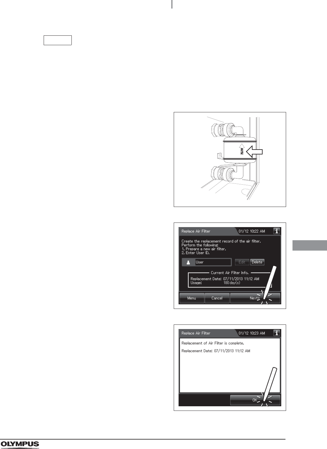
6With the FLOW indicator pointing upwards,
attach a new air filter by fitting into the two
connectors until they click. Then lightly pull the
air filter to confirm that the sleeves fit on the
connectors.
Figure 8.117
7Press the “Next” button.
Figure 8.118
8Press the “OK” button.
Figure 8.119
406
8.5 Replacing the air filter (MAJ-823)
OER-Elite OPERATION MANUAL
Ch.8
When entering the Lot number of air filter
If the lot number management is activated, enter the Lot number according to the following
procedure.
NOTE
• The Lot number is printed on a label affixed to the package containing the air filter.
• The lot number of the air filter can be recorded. For the setting change method,
refer to Section 4.15, “Filter lot number management”.
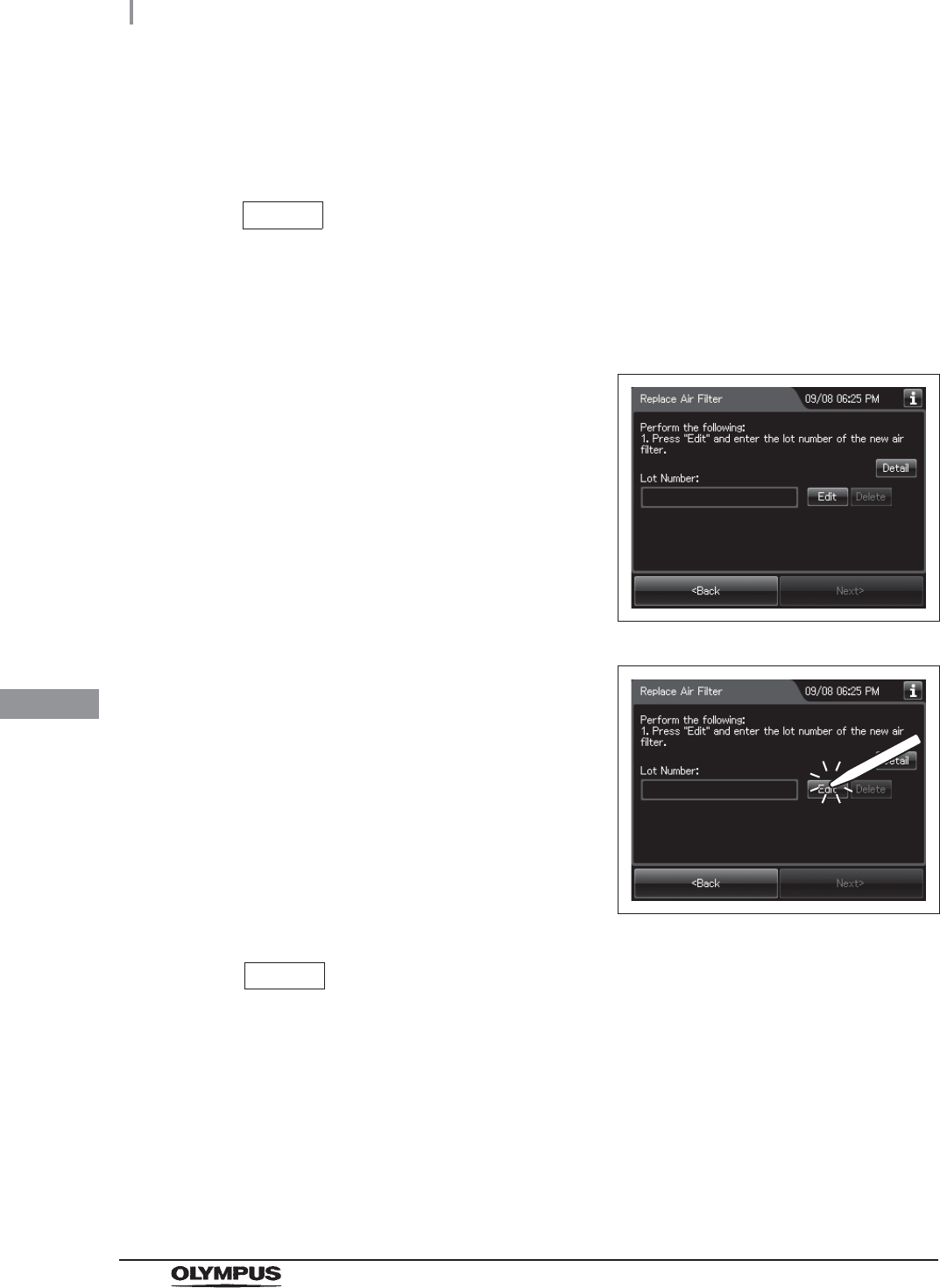
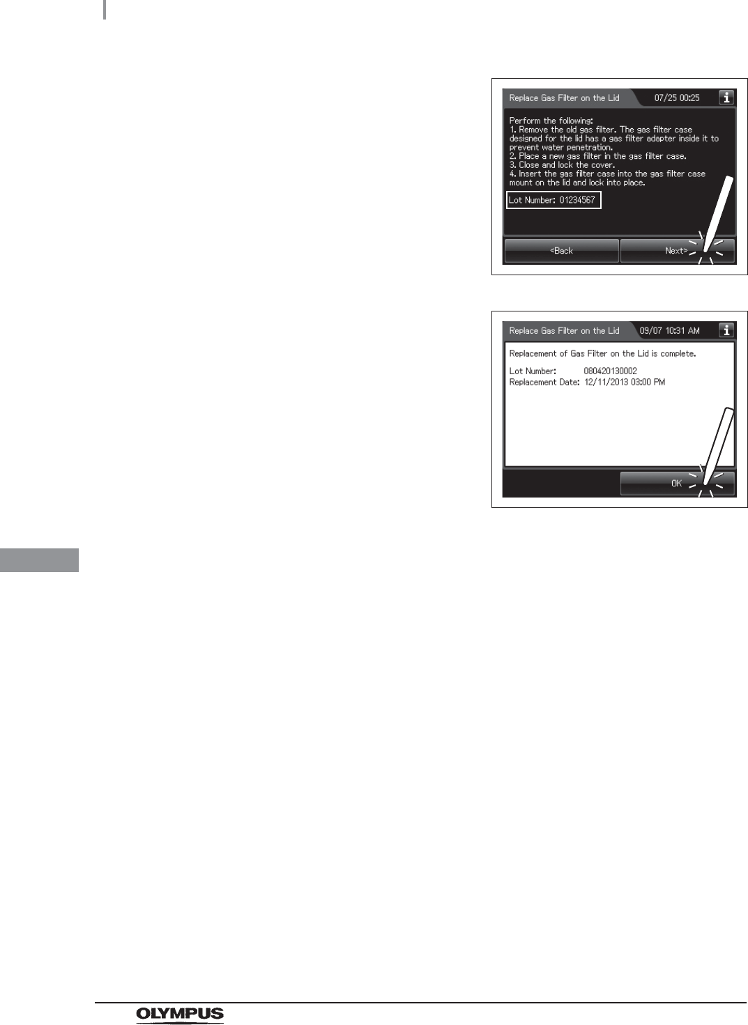
1If the filter lot number management of the air
filter is active, the touch screen displays a
screen as shown in following figure after Step 7
in “Replacing the air filter” on page 403.
Figure 8.120
2Press the “Edit” button to display the lot entry
screen.
Figure 8.121
NOTE
If the “Delete” button is pressed, the entered Lot No can be deleted.
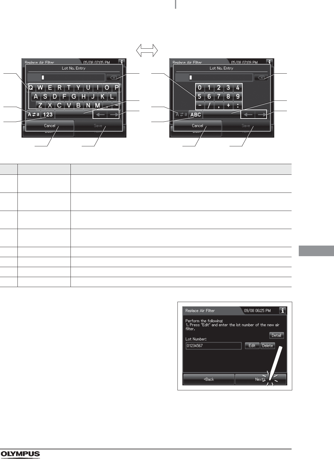
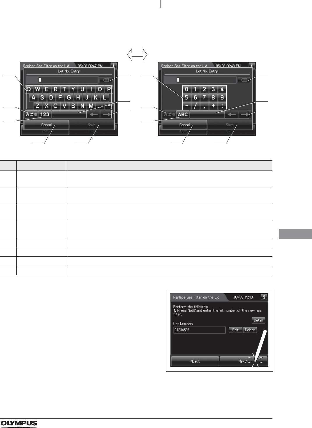
3Enter the Lot No of the new air filter by the software keyboard on the touch screen
and press the “Save” button.
8.5 Replacing the air filter (MAJ-823)
407
OER-Elite OPERATION MANUAL
Ch.8
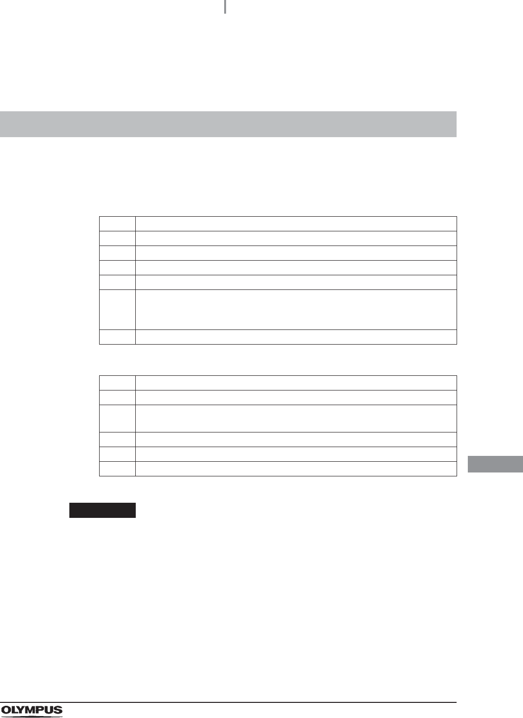
No. Button Note
Alphabet/
Numeral key
Enter the alphabet or a numeral.
2 Uppercase/
Lowercase button
Press “Uppercase/lowercase” button to switch alphabet character on the soft keyboard
between uppercase characters and lowercase characters.
3 Numeric/
Alphabetic button
Press “Numeric or Alphabetic” button to switch the input mode between a numeral and
the alphabet.
4 Backspace button Press the “Backspace” button to delete the left character of a cursor.
When a cursor is on the left edge, this button turns gray and becomes unavailable.
5 Space button Press the “Space” button to insert a space character.
6 Cursor move button Press the cursor move button to move the cursor left or right.
7 Cancel button Return to the previous screen without saving the setting value.
8 Save button Return to the previous screen and save the entered value.
4Press the “Next” button.
Figure 8.122
41
2
3
5
6
7 8
41
2
3
5
6
7 8
Alphabet input Numeral input
408
8.5 Replacing the air filter (MAJ-823)
OER-Elite OPERATION MANUAL
Ch.8
Inspecting air leakage from the air filter connectors
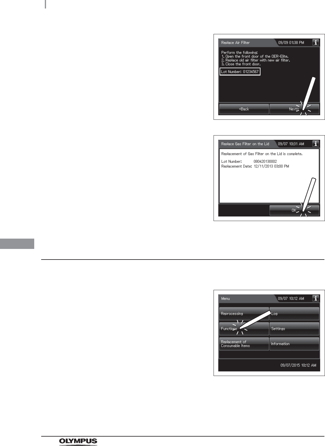
5Check the displayed lot number and press the
“Next” button.
Figure 8.123
6Press the “OK” button.
Figure 8.124
1Close the lid by pushing it until it clicks.
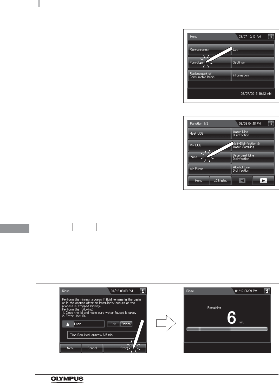
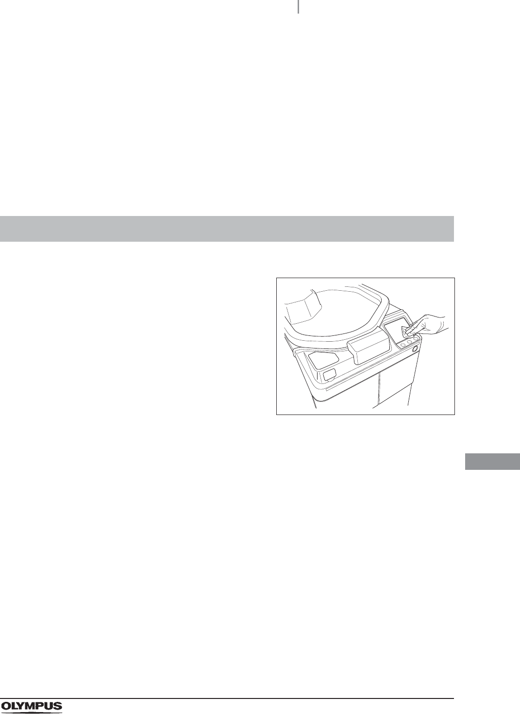
2Press the “Function” button on the Menu
screen.
Figure 8.125
8.5 Replacing the air filter (MAJ-823)
409
OER-Elite OPERATION MANUAL
Ch.8
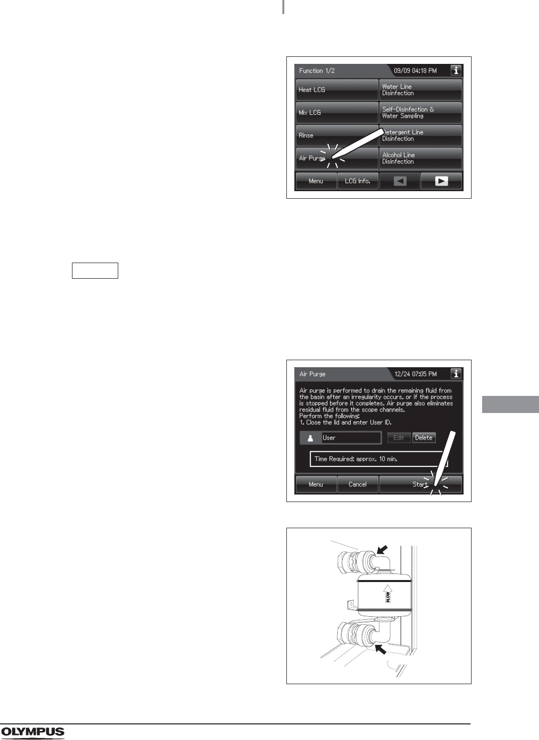
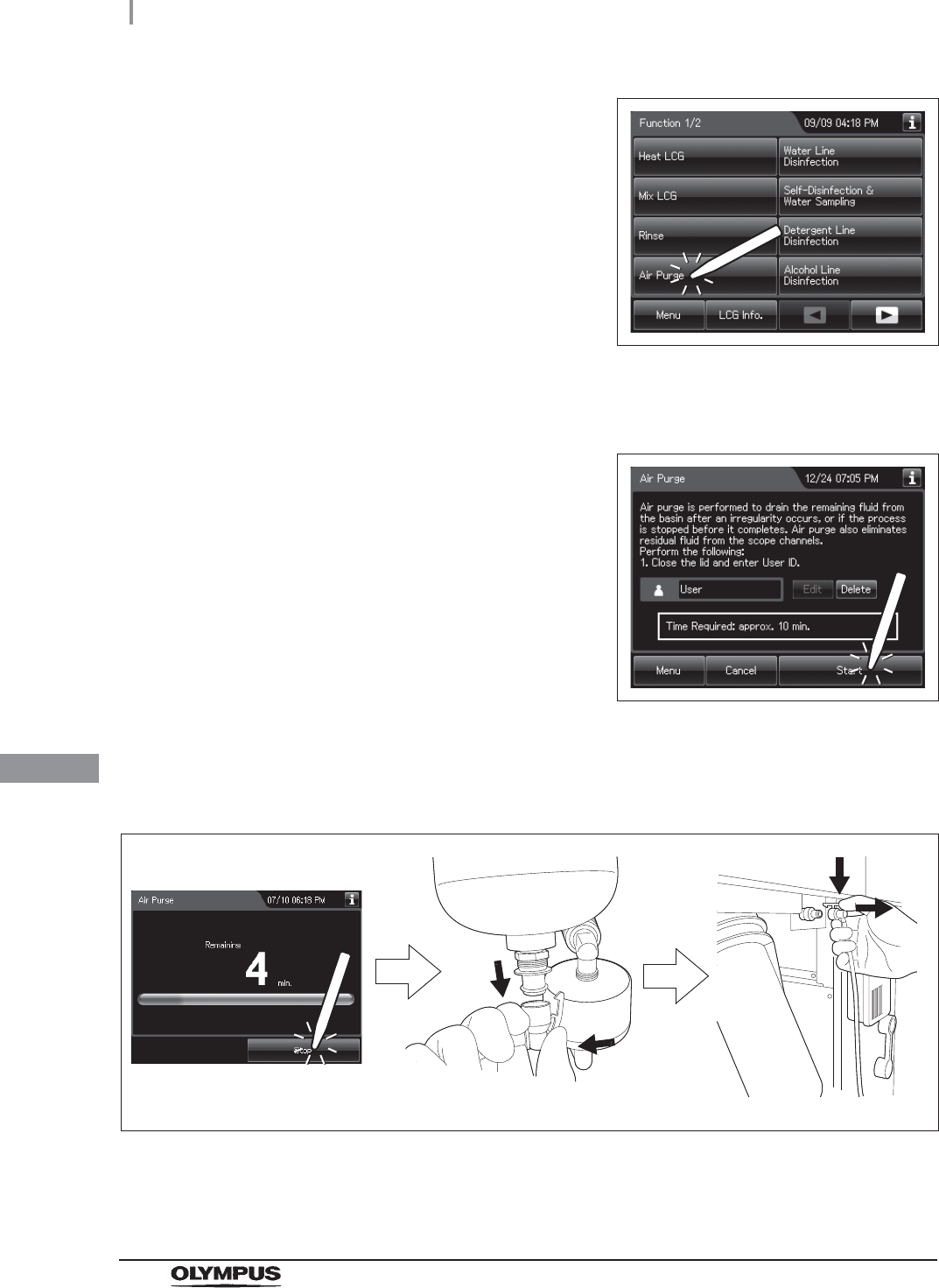
3Press the “Air Purge” button.
Figure 8.126
4Enter the operator's user ID. For the detailed procedures, refer to Section 3.6,
“Entering ID” (If applicable).
NOTE
• The input of the user ID can be omitted by modifying the user ID input setting. For
details, refer to Section 4.5, “User ID Setting”.
• If the “Delete” button is pressed, the entered ID can be deleted.
5Press the “Start” button.
Figure 8.127
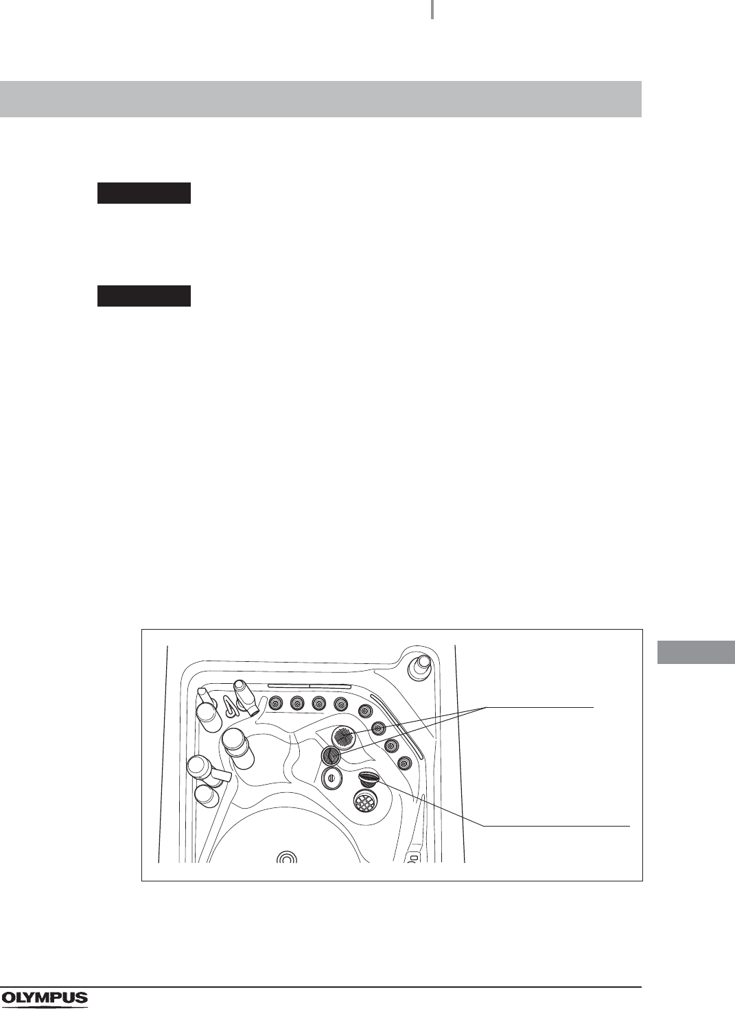
6When for about 40 seconds after air purge
started. Then, touch the air filter connectors to
ensure that air is not leaking out. Also, ensure
that the connectors do not produce a whistling
sound, which would mean there is an air leak.
Figure 8.128
Connector
Connector
410
8.5 Replacing the air filter (MAJ-823)
OER-Elite OPERATION MANUAL
Ch.8
NOTE
It takes about 40 seconds to feed air into the air filter.
7Press the “Stop” button on the touch screen to end Air Purge. If an air leak is detected
or the error code [E021] is displayed, reinstall the air filter as described in
͆Replacing the air filter” on page 403
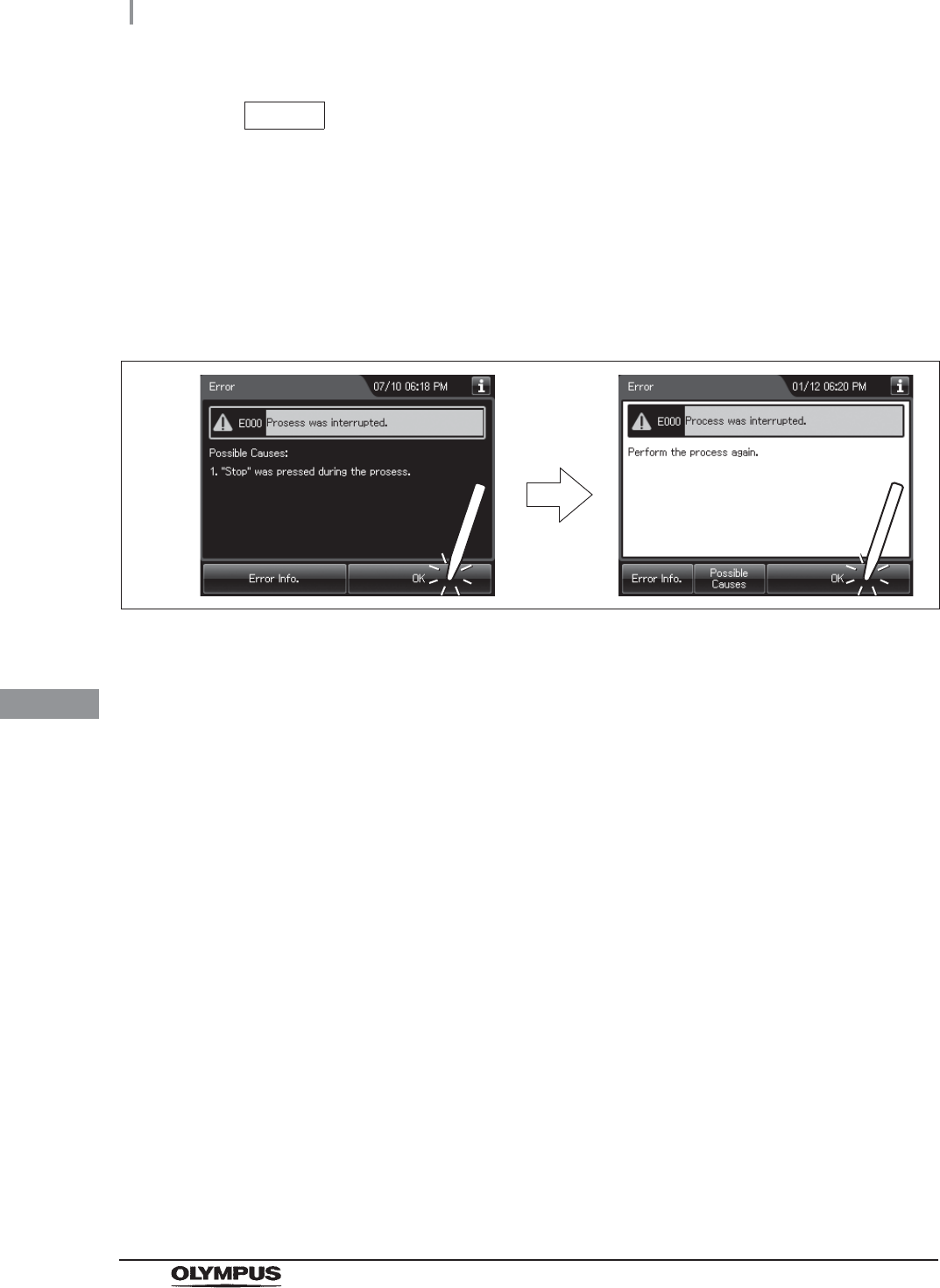
8The touch screen displays the error code [E000]. Press the “OK” button repeatedly
until the error screen is closed.
Figure 8.129
8.6 Replacing the gas filter (MAJ-822)
411
OER-Elite OPERATION MANUAL
Ch.8
Replace two gas filters every month or whenever the odor of the disinfectant solution seems to have
increased, whichever comes first.
To create the record of the replacement of the gas filter, select “Replace Gas Filter on the Lid” or
“Replace Gas Filter on the Tank” in the Replacement of Consumable Items menu.
WARNING
The disinfectant vapor generated by the reprocessor has been proven safe in
in-house testing. Nevertheless, as individual reactions to the disinfectant may vary,
Olympus recommends the use of gas filters and enhanced protection by observing
the ventilation conditions given in “Ensuring the safety of reprocessing
personnel” on page 12. The use of the gas filter does not replace the need for
proper room ventilation.
CAUTION
• Always be sure to attach the specified gas filter. Otherwise, the vapor of the
disinfectant may not be eliminated sufficiently.
• Do not block the ventilation openings on the gas filter cases with the replacement
date indication sticker or any other foreign material. Blocking the ventilation not
only hinders deodorization but may also cause the reprocessor to malfunction.
• If the odor of the disinfectant solution seems to have increased after replacement of
gas filters, contact Olympus.
• If the gas filter is expired, the performance of gas filter may decrease and cannot
remove the odor of disinfectant solution sufficiently.
NOTE
When the gas filter counter setting is activated, the filter replacement indicator can
be displayed on the top right of the touch screen and on the “Replace Gas Filter on
the lid” and/or “Replace Gas Filter on the Tank” button on the Replacement of
Consumable Items menu when the counter setting value is reached. For the gas
filter counter setting, refer to Section 4.14, “Filter replacement indicator”.
8.6 Replacing the gas filter (MAJ-822)
412
8.6 Replacing the gas filter (MAJ-822)
OER-Elite OPERATION MANUAL
Ch.8
Required items
Table 8.8
Replacing the gas filter on the lid
NOTE
If you do not need to create the record of the replacement of the gas filter, the
following operations of GUI can be skipped.
Check Required items
Gas filter (MAJ-822) (u 2 pieces)
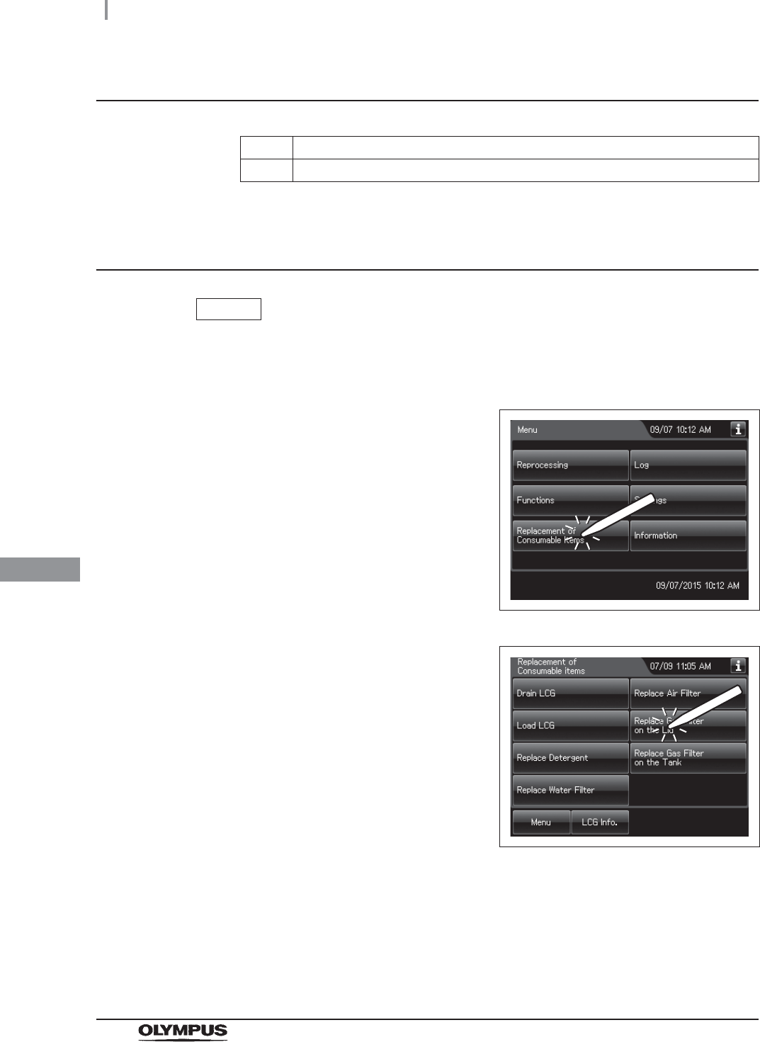
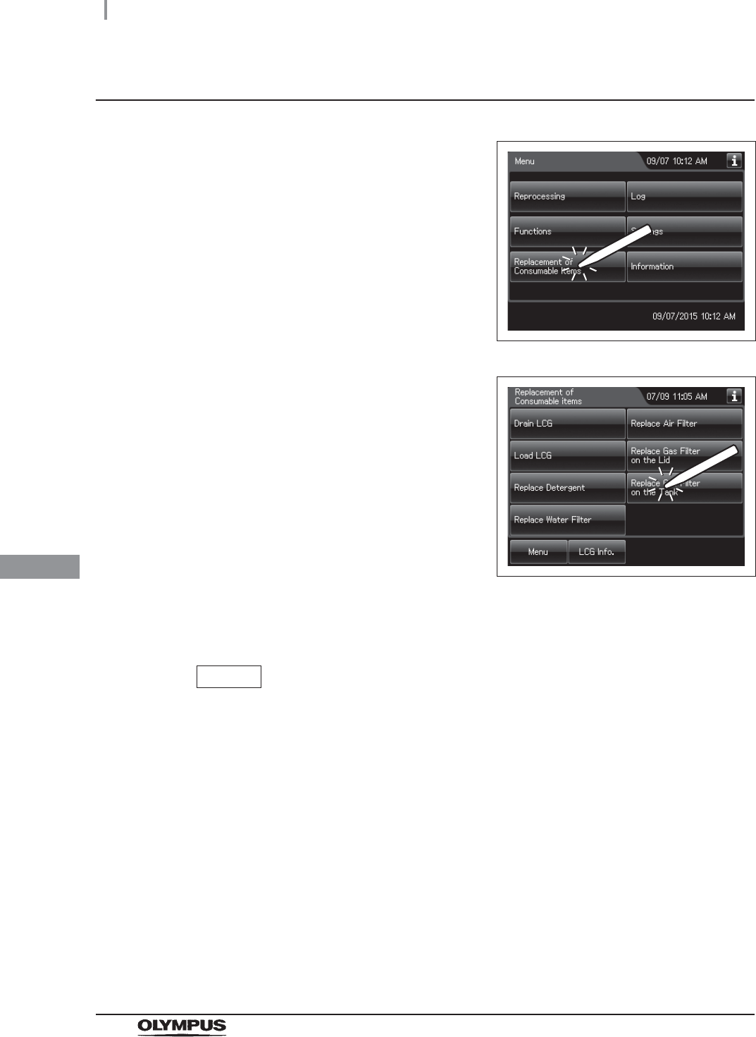
1Press the “Replacement of Consumable items”
button on the Menu screen.
Figure 8.130
2Press the “Replace Gas Filter on the Lid”
button.
Figure 8.131
3Enter the operator's user ID. For the detailed procedures, refer to Section 3.6,
“Entering ID” (If applicable).
8.6 Replacing the gas filter (MAJ-822)
413
OER-Elite OPERATION MANUAL
Ch.8
NOTE
• The input of the user ID can be omitted by modifying the user ID input setting. For
details, refer to Section 4.5, “User ID Setting”.
• If the “Delete” button is pressed, the entered ID can be deleted.
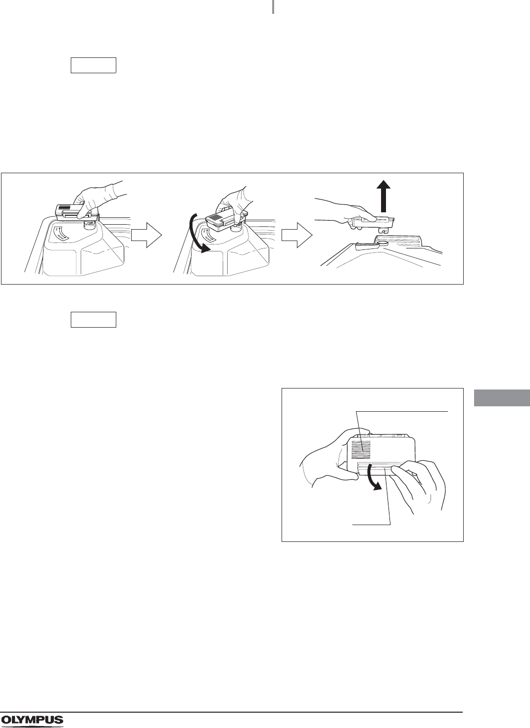
4Remove the gas filter case from the deep part of the lid.
Figure 8.132
NOTE
When the reprocessor is shipped from the factory, the gas filters are not installed in
the reprocessor.
5Unlock each gas filter case cover and open it.
Figure 8.133
Ventilation opening
Lock
414
8.6 Replacing the gas filter (MAJ-822)
OER-Elite OPERATION MANUAL
Ch.8
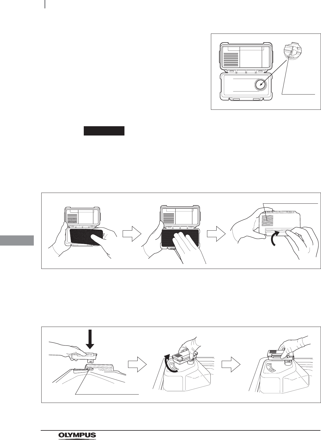
6Remove the old gas filter. The gas filter case
designed for the lid has a gas filter adapter
(splash guard) inside of it to prevent water
droplet penetration.
Figure 8.134
CAUTION
Do not discard the gas filter adapter (splash guard). If the adapter is not installed to
the gas filter case, disinfectant solution may adhere to the gas filter during
processes such as reprocessing process.
7Place a new gas filter in the gas filter case.
Figure 8.135
8Close and lock the cover. Do not to catch the gas filter when closing the cover.
9Insert the gas filter case designed for the reprocessing basin (the one with gas filter
adapter (splash guard) attached to it) into the mount on the deep part of the lid, and
then turn it all the way in the direction shown below until it is stopped.
Figure 8.136
Gas filter
adapter
(splash
guard)
Ventilation opening
Gas filter case mount
8.6 Replacing the gas filter (MAJ-822)
415
OER-Elite OPERATION MANUAL
Ch.8
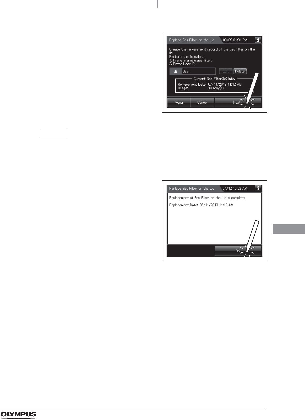
10 Press the “Next” button.
Figure 8.137
NOTE
When the lot number management of the gas filter is activated, the lot number of
the gas filter is entered after Step 10. For details, refer to “When entering the lot
number of the gas filter on the lid and tank” on page 419.
11 Press the “OK” button.
Figure 8.138
416
8.6 Replacing the gas filter (MAJ-822)
OER-Elite OPERATION MANUAL
Ch.8
Replacing the gas filter on the disinfectant solution tank
1Press the “Replacement of Consumable items”
button on the Menu Screen.
Figure 8.139
2Press the “Replace Gas Filter on the Tank”
button.
Figure 8.140
3Enter the operator's user ID. For the detailed procedures, refer to Section 3.6,
“Entering ID” (If applicable).
NOTE
• The input of the user ID can be omitted by modifying the user ID input setting. For
details, refer to Section 4.5, “User ID Setting”.
• If the “Delete” button is pressed, the entered ID can be deleted.
8.6 Replacing the gas filter (MAJ-822)
417
OER-Elite OPERATION MANUAL
Ch.8
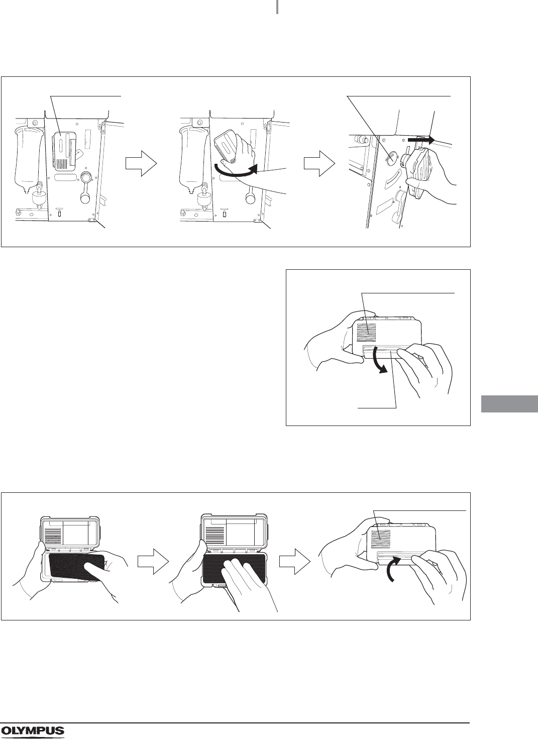
4Open the front door and remove the gas filter case from the top right position.
Figure 8.141
5Unlock each gas filter case cover and open it.
Figure 8.142
6Remove the old gas filter.
7Place the new gas filter in the gas filter case.
Figure 8.143
8Close and lock the cover. Do not catch the gas filter when closing the cover.
Gas filter case Gas filter case mount
Ventilation opening
Lock
Ventilation opening
418
8.6 Replacing the gas filter (MAJ-822)
OER-Elite OPERATION MANUAL
Ch.8
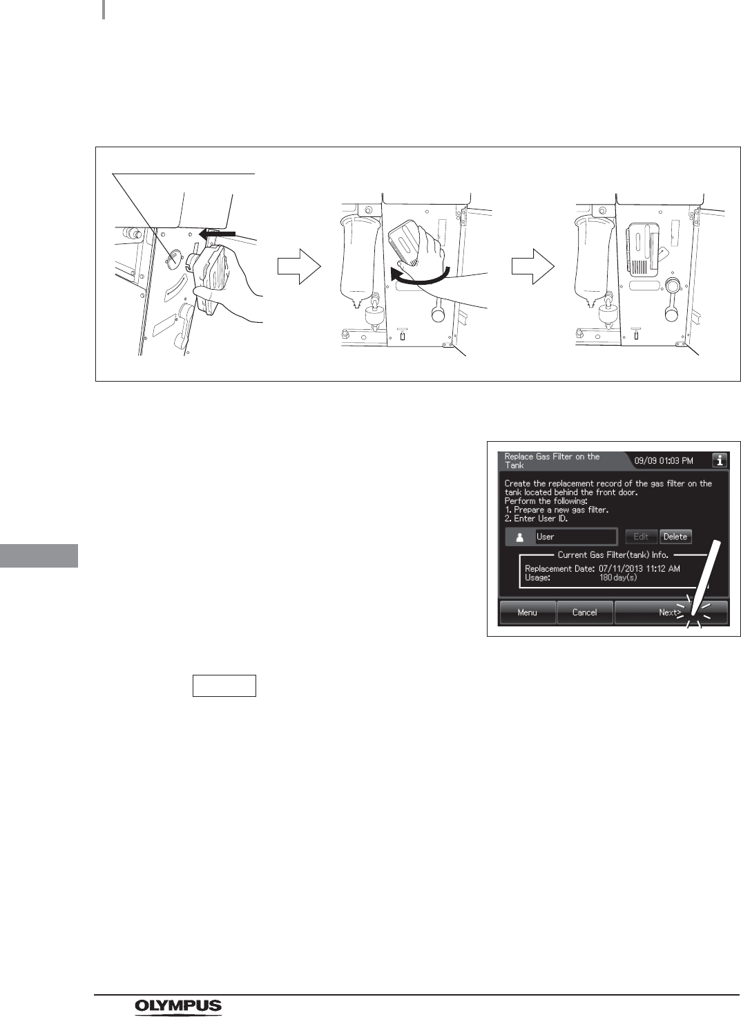
9Insert the gas filter case designed for the disinfectant solution tank into the gas filter
case mount at the top right of the inside of the front door, and then turn it all the way in
the direction shown below until it is stopped.
Figure 8.144
10 Close the front door.
11 Press the “Next” button.
Figure 8.145
NOTE
When the lot number management of the water filter is activated, the lot number of
the water filter is entered after Step 11. For details, refer to “When entering the
lot number of the gas filter on the lid and tank” on page 419.
Gas filter case mount
8.6 Replacing the gas filter (MAJ-822)
419
OER-Elite OPERATION MANUAL
Ch.8
When entering the lot number of the gas filter on the lid and tank
If the lot number management is activated, enter the Lot number according to the following
procedure.
NOTE
• The Lot number is printed on a label affixed to the package containing the gas filter.
• The lot number of the gas filter can be recorded. For the setting change method,
refer to Section 4.15, “Filter lot number management”.
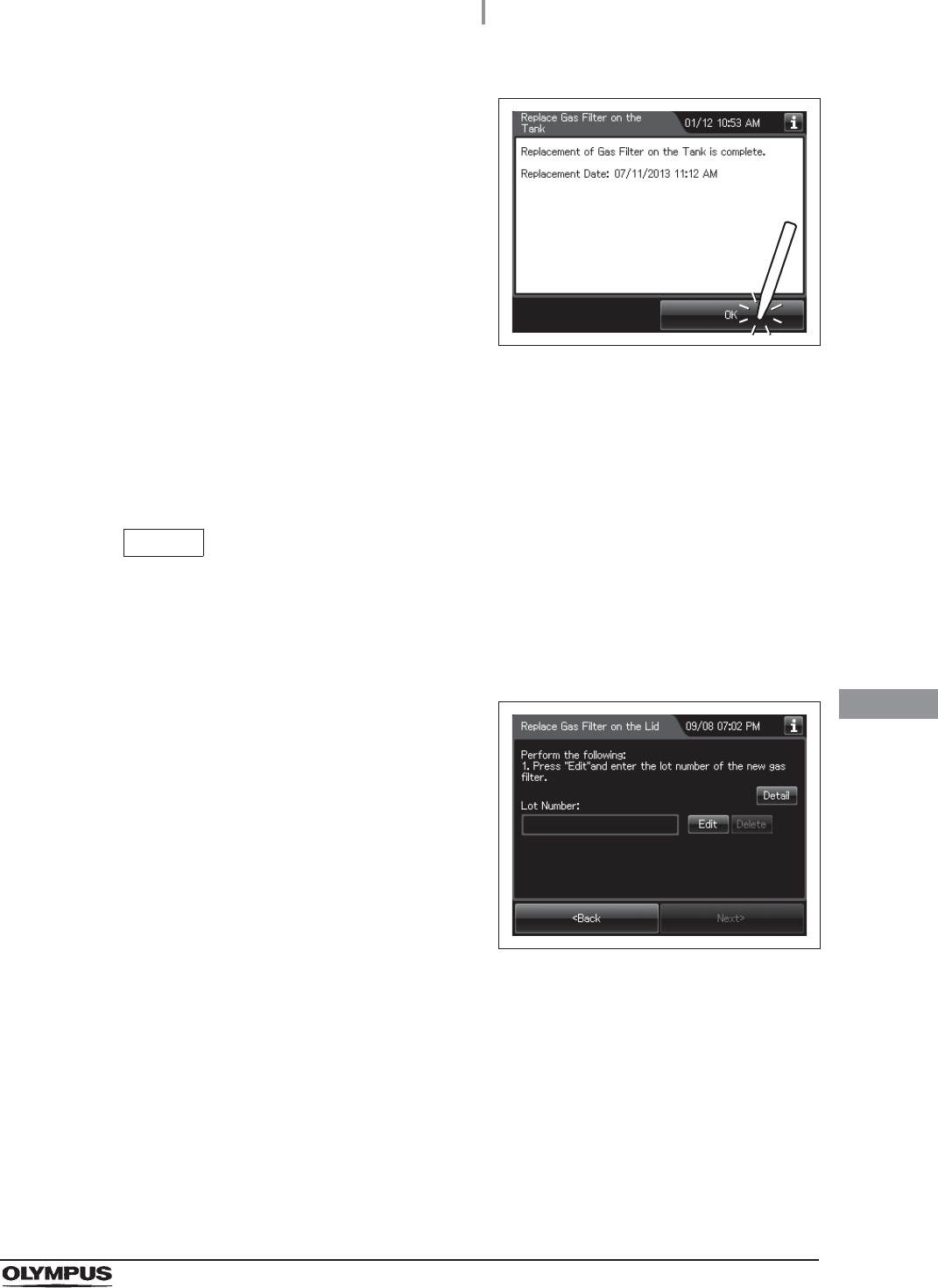
12 Press the “OK” button.
Figure 8.146
1If the filter lot number management of the gas
filter (Lid and/or Tank) is active, the touch
screen displays a screen as shown in following
figure after Step 10 in “Replacing the gas
filter on the lid” on page 415 or Step 11 in
“Replacing the gas filter on the disinfectant
solution tank” on page 418. Press the “Next”
button.
Figure 8.147
420
8.6 Replacing the gas filter (MAJ-822)
OER-Elite OPERATION MANUAL
Ch.8
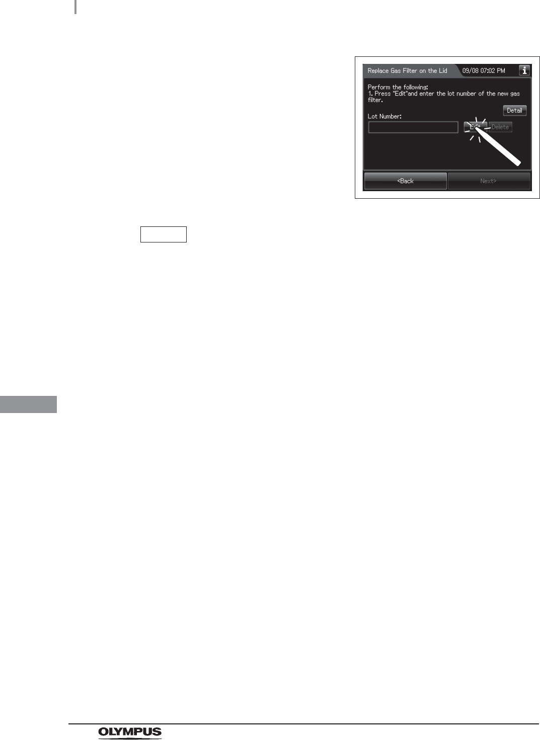
2Press the “Edit” button to display the lot entry
screen.
Figure 8.148
NOTE
If the “Delete” button is pressed, the entered Lot No can be deleted.
3Enter the lot number of the new gas filter by the software keyboard on the touch
screen and press the “Save” button.
8.6 Replacing the gas filter (MAJ-822)
421
OER-Elite OPERATION MANUAL
Ch.8
No. Button Note
1 Alphabet/Numeral
key
Enter the alphabet or a numeral.
2 Uppercase/
Lowercase button
Press “Uppercase/lowercase” button to switch alphabet character on the soft keyboard
between uppercase characters and lowercase characters.
3 Numeric/Alphabetic
button
Press “Numeric or Alphabetic” button to switch the input mode between a numeral and
the alphabet.
4 Back space button Press the “Backspace” button to delete the left character of a cursor.
When a cursor is on the leftmost, this button becomes gray and cannot be pressed.
5 Space button Press the “Space” button to insert a space character.
6 Cursor move button Press the cursor move button to move the cursor left or right.
7 Cancel button Return to the previous screen without saving the setting value.
8 Save button Return to the previous screen and save the entered value.
4Press the “Next” button.
Figure 8.149
41
2
3
5
6
7 8
41
2
3
5
6
7 8
Alphabet input Numeral input
422
8.6 Replacing the gas filter (MAJ-822)
OER-Elite OPERATION MANUAL
Ch.8
5Check the displayed lot number and press the
“Next” button.
Figure 8.150
6Press the “OK” button.
Figure 8.151

9.1 Periodic inspection
423
OER-Elite OPERATION MANUAL
Ch.9
Chapter 9 Routine Maintenance
To ensure safe operation of the reprocessor, it should be cleaned and inspected regularly. Parts and
consumables should be added or replaced as required.
WARNING
• When using the disinfectant solution and alcohol, Olympus recommends the use of
gas filters and running this reprocessor in well-ventilated areas.
Refer to the following association’s guidelines related to ventilation:
If the person performing the inspection or maintenance exhibits an allergic reaction
or symptoms, no matter how slight, they should discontinue the task and vacate the
room.
• Be sure to perform all the inspections, cleaning, replacement of consumables and
other tasks described in this chapter. Otherwise, this reprocessor may cease to
operate and perform as expected.
• When inspecting or cleaning this reprocessor, always wear appropriate personal
protective equipment, such as goggles, face mask, moisture-resistant clothing, and
chemical-resistant gloves that fit properly and are long enough so that your skin is
not exposed.
• If you find any problems or observe an irregularity, do not use the reprocessor and
contact Olympus. If the reprocessor is used when an irregularity is found, the
reprocessor may malfunction. Water leakage, electric shock, burns, and/or fire may
also result.
9.1 Periodic inspection
SGNA (Society of Gastroenterology Nurses and Associates)
ASGE (American Society of Gastroenterological Endoscopy)
APIC (Association for Professionals of Infection Control and Epidemiology)
AORN (Association of Preoperative Registered Nurses)
ASTM (American Society for Testing and Materials)
OSHA (Occupational Safety and Health Administration)
ACGIH (American Conference of Governmental Industrial Hygienists)
NIOSH (National Institute for Occupational Safety and Health)
AIA (American Institute of Architects)
424
9.1 Periodic inspection
OER-Elite OPERATION MANUAL
Ch.9
WARNING
• Alcohol is flammable. Before handling the alcohol, carefully read the cautions for
use, become fully acquainted with all safety materials, and use the alcohol as
instructed.
Table 9.2
Table 9.3
Check Monthly maintenance
Section 8.6, “Replacing the gas filter (MAJ-822)”
Section 8.4, “Replacing the water filter (MAJ-824 or MAJ-2318)”*1
*1 Using a prefilter of 0.45 micron or less can extend the life of the water filter
(MAJ-824 or MAJ-2318). If the prefilter is properly installed, and one of the prefilters
is 0.45 microns or less, it is recommended that the water filter (MAJ-824 or
MAJ-2318) be replaced at least once every 6 months. If there is no prefilter installed
then it is recommended that the water filter (MAJ-824 or MAJ-2318) be replaced at
least every 30 days. For information on the Water Pre-filtration system, contact
Olympus.
Section 7.7, “Water line disinfection”
Section 8.5, “Replacing the air filter (MAJ-823)”
Section 9.2, “Cleaning the detergent/alcohol drawer”
Section 9.3, “Cleaning the accessories and accessory holder”
Table 9.1
Check Weekly maintenance
Section 9.4, “Cleaning the alcohol tank”
Check Work to be performed as required
Section 8.3, “Replacing the detergent tank”
Section 9.5, “Checking cassette cutters”
Section 9.6, “Cleaning the disinfectant bottle drawer”
Section 8.2, “Replacing the disinfectant solution”
Section 9.7, “Cleaning the mesh filter in the water supply hose connector”
Section 9.8, “Replacing the fuse”
Section 7.9, “Detergent line disinfection”
Section 7.10, “Alcohol line disinfection”
Section 9.9, “Preparing the reprocessor for long-term storage”
Section 9.10, “Care and maintenance after long-term storage”
9.2 Cleaning the detergent/alcohol drawer
425
OER-Elite OPERATION MANUAL
Ch.9
Clean the detergent/alcohol drawer every month.
CAUTION
Pay attention to not to injure your hand by hitting the detergent/alcohol drawer.
9.2 Cleaning the detergent/alcohol drawer
1Pull out the detergent/alcohol drawer.
2Disconnect the tubes from the detergent tank and alcohol tank, and take both tanks
out of the drawer.
3Take the detergent/alcohol inner tray out of the detergent/alcohol drawer.
4Clean the detergent/alcohol inner tray in fresh running water.
5After cleaning, dry it thoroughly with a clean cloth.
6Place the detergent/alcohol inner tray back on the detergent/alcohol drawer.
7Place the detergent tank and alcohol tank on the detergent/alcohol drawer and
connect the tubes to the original positions on the tanks.
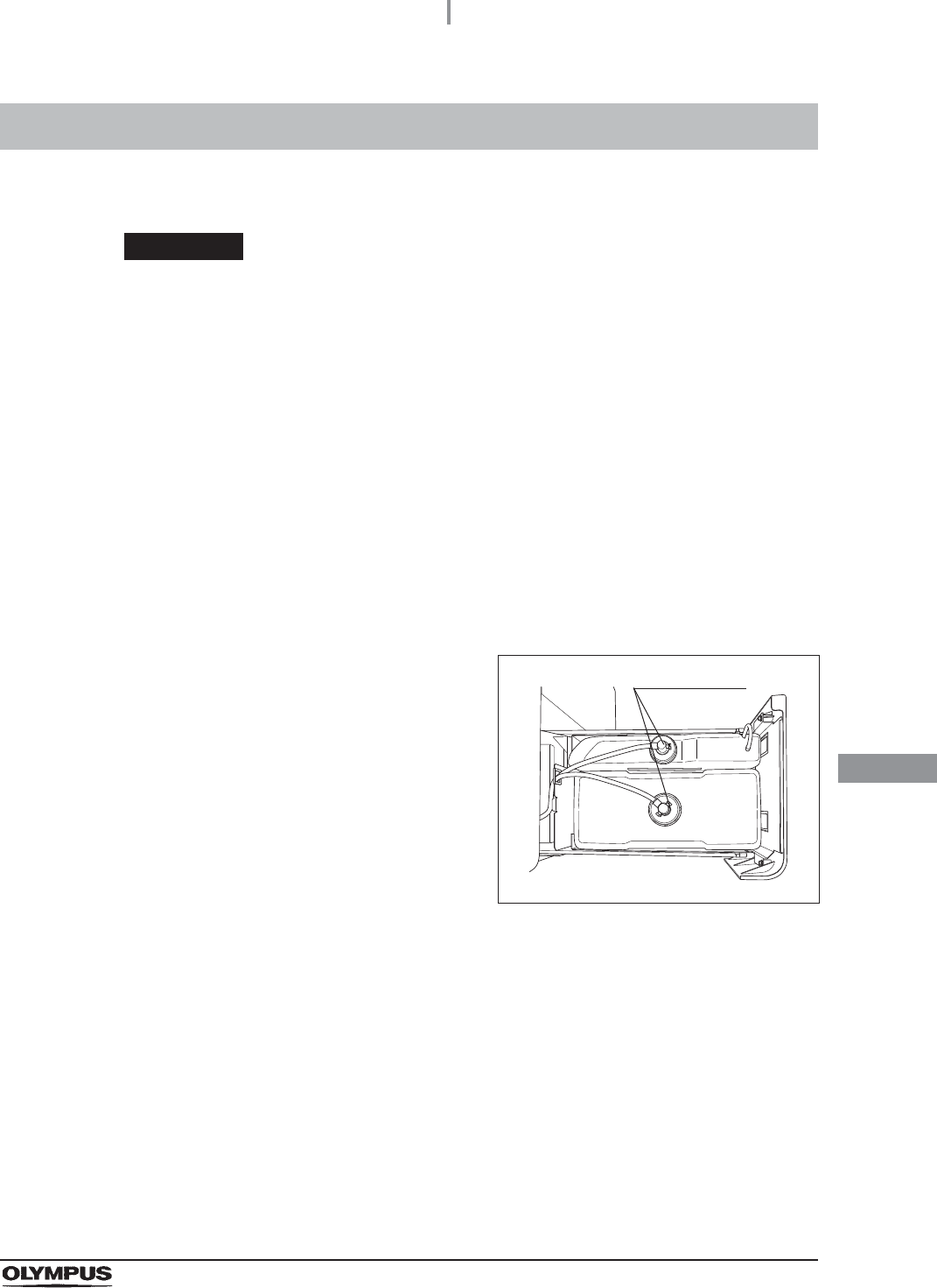
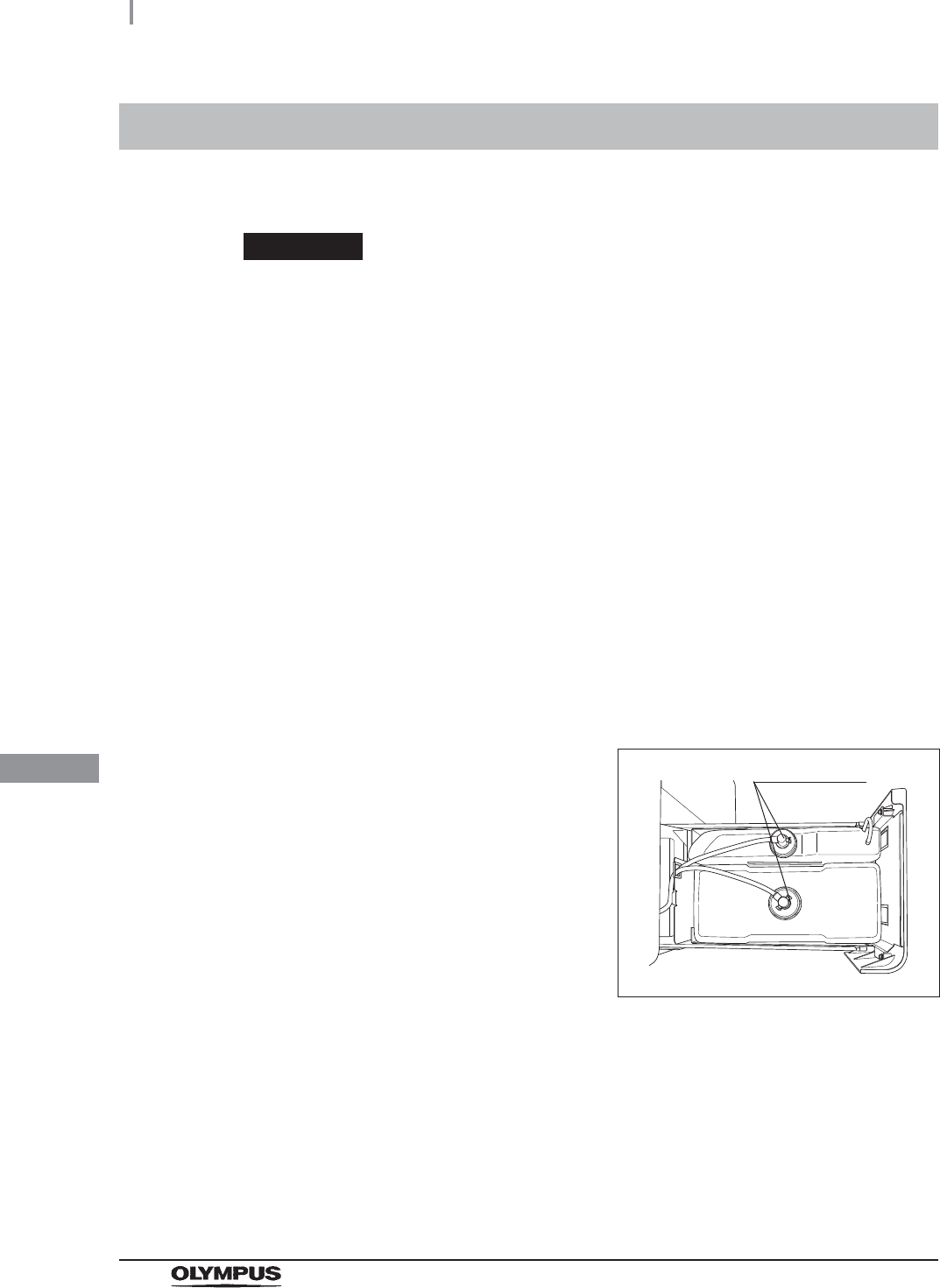
8Turn the connectors to correct the orientations
of the tubes as shown Figure 9.1.
Figure 9.1
9Close the detergent/alcohol drawer.
Connectors
426
9.3 Cleaning the accessories and accessory holder
OER-Elite OPERATION MANUAL
Ch.9
As the accessories listed below tend to attract dirt and dust, they should be cleaned at least every
month and stored in a clean environment. The accessory holder used for storage should also be kept
clean in the same way.
• Connecting tubes
• Filter tubes
• Hoses
• Gas filter case excluding the gas filter
• Gas filter adapter (splash guard), etc.
• Accessory holder
• Card holders
Required items
Table 9.4
Cleaning the accessories and accessory holder
9.3 Cleaning the accessories and accessory holder
Check Required items
70% ethyl alcohol or 70% isopropyl alcohol
Clean cloth
Neutral detergent
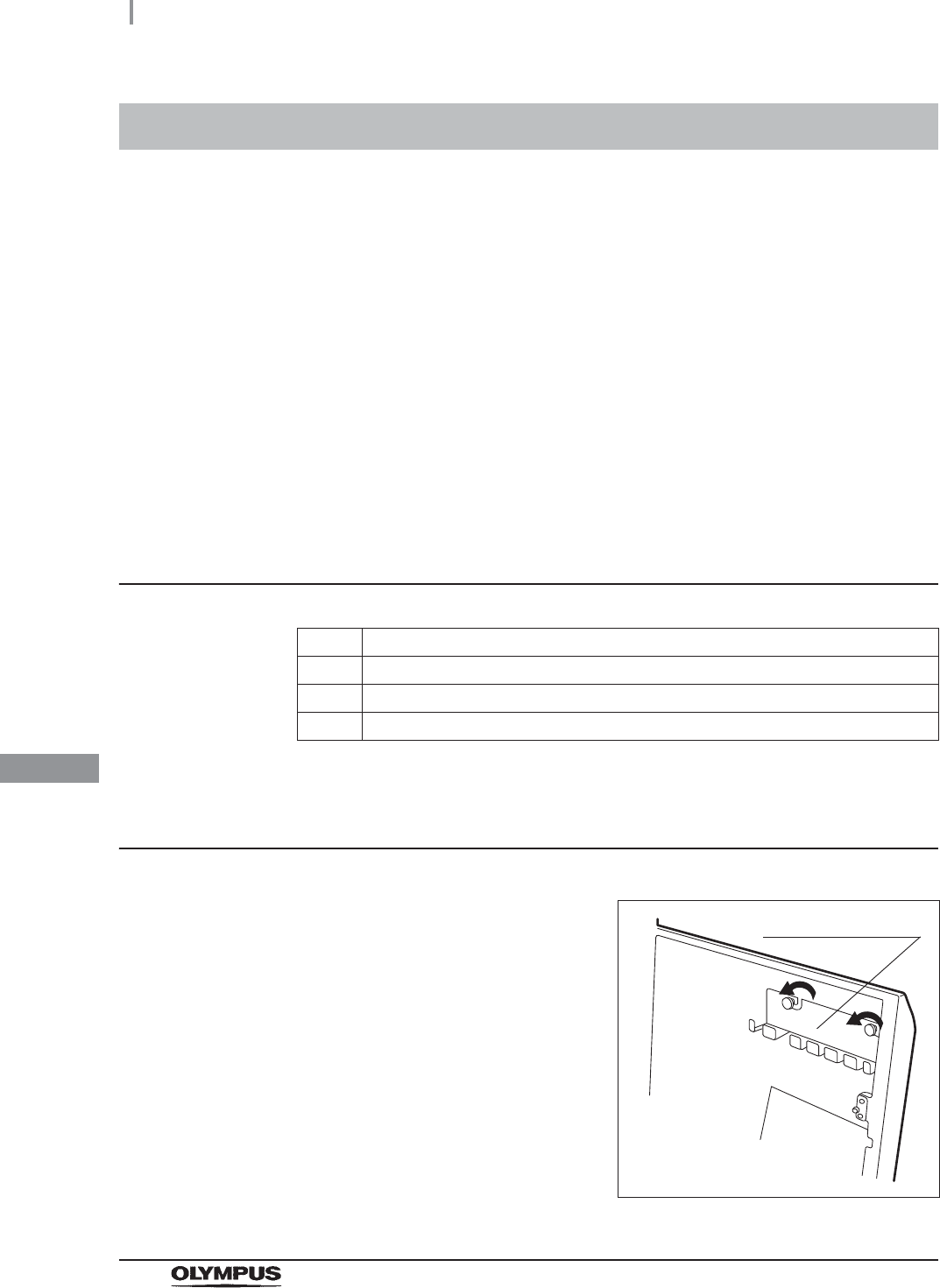
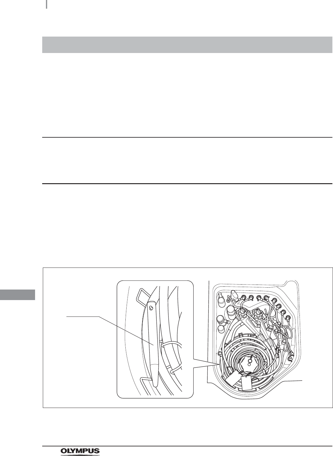
1Remove the accessory holder from the back
side of the front door by loosening the two
retaining screws.
Figure 9.2
Accessory holder
9.3 Cleaning the accessories and accessory holder
427
OER-Elite OPERATION MANUAL
Ch.9
CAUTION
Do not hook connector tubes on the accessory holder in a disorderly fashion as this
could make it difficult or impossible to open and close the front door and may also
damage the accessories.
2Using a cloth moistened with neutral detergent, clean the external surfaces of the
accessory holder and the accessories listed above, rinse them in running water, and
wipe them with a clean cloth. To prevent the growth of microorganisms, it is also
recommended to wipe the accessories and accessory holder with a cloth moistened
with 70% ethyl alcohol or 70% isopropyl alcohol.
3Dry the accessories and accessory holder thoroughly and store them in a clean place
near the device.
4Attach the accessory holder to the back side of the front door using the two retaining
screws.
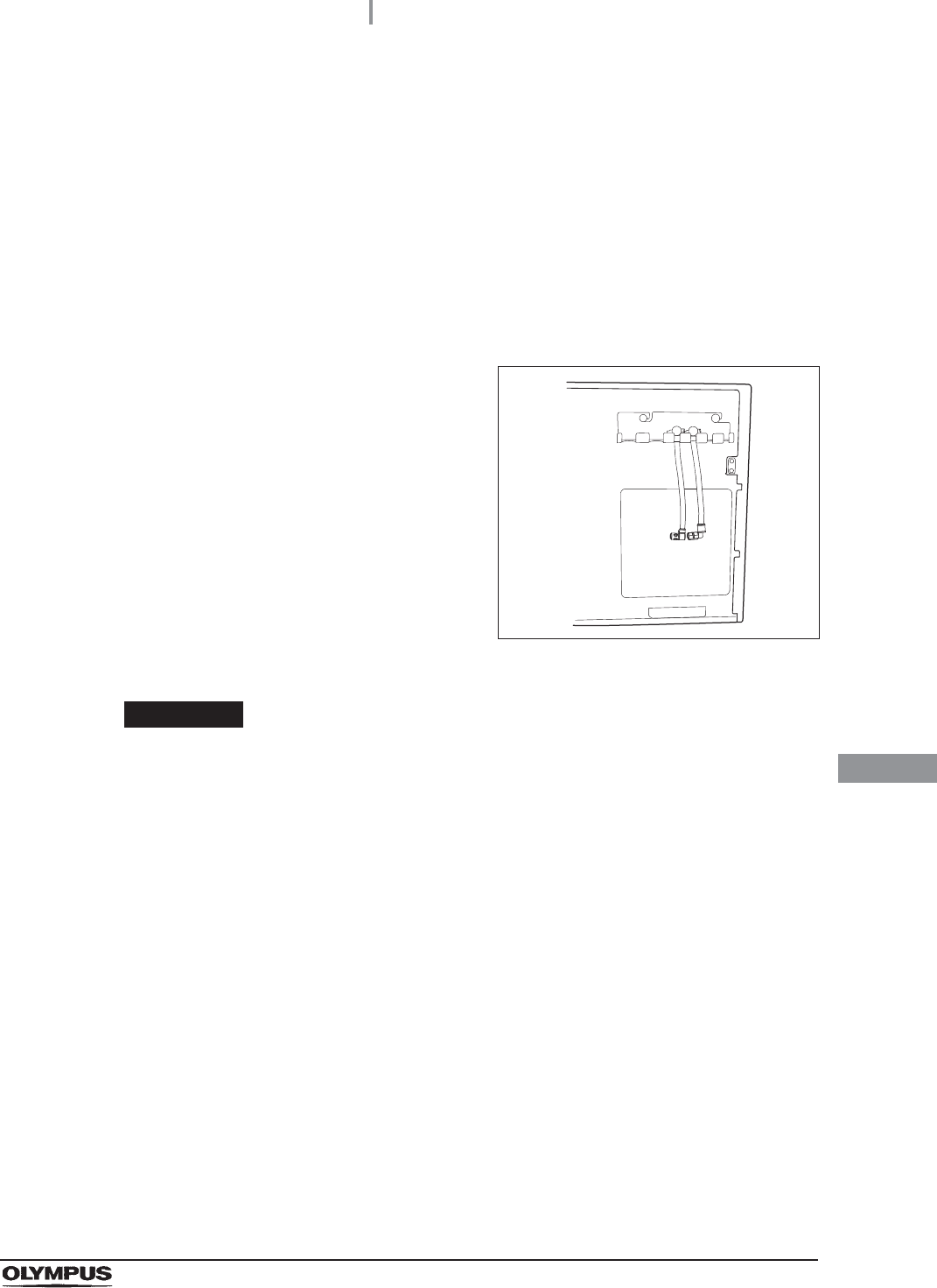
5Store the frequently used connector tubes in
the accessory holder. Note that the accessory
holder cannot accommodate all of the
connector tubes.
Figure 9.3
428
9.4 Cleaning the alcohol tank
OER-Elite OPERATION MANUAL
Ch.9
Clean the alcohol tank every week.
CAUTION
Do not tilt the alcohol or detergent tank while fluid is still inside. Otherwise, the fluid
may spill.
9.4 Cleaning the alcohol tank
1Pull out the detergent/alcohol drawer.
2Disconnect the tube from the alcohol tank and take the tank out of the
detergent/alcohol drawer.
3Empty the tank.
4Rinse inside of the tank with running water. Repeat this rinse process several times
with fresh water to rinse it thoroughly.
5Using a cloth moistened with neutral detergent, clean the external surface, rinse the
external surface of the tank in running water, and wipe it with a clean cloth. To prevent
growth of microorganisms, it is also recommended to wipe the outside of the tank with
a cloth moistened with 70% ethyl alcohol or 70% isopropyl alcohol.
6Drain out the water inside the tank, dry it thoroughly, put it back on the
detergent/alcohol drawer and attach the cap and tube to it.
7Turn the connectors to correct the orientations
of the tubes as shown below.
Figure 9.4
8Close the detergent/alcohol drawer.
Connectors

9.5 Checking cassette cutters
429
OER-Elite OPERATION MANUAL
Ch.9
Inspect the cassette cutters when replacing the disinfectant solution. For details, refer to Section 8.2,
“Replacing the disinfectant solution”.
It is necessary to clean the disinfectant bottle drawer if it is dirty or if any disinfectant solution spills into
the drawer. The disinfectant solution bottle drawer can be opened only when replacing the
concentrated disinfectant solution. For details, refer to Section 8.2, “Replacing the disinfectant
solution”.
CAUTION
Pay attention to not to injure your hand by hitting the disinfectant bottle drawer.
9.5 Checking cassette cutters
9.6 Cleaning the disinfectant bottle drawer
430
9.7 Cleaning the mesh filter in the water supply hose connector
OER-Elite OPERATION MANUAL
Ch.9
When the reprocessor stops with error code [E001], the water filter should be replaced first. However,
if the reprocessor stops again with error code [E001], clean the mesh filter as described below.
Required items
Table 9.5
Cleaning the mesh filter in the water supply hose
connector
NOTE
To relieve the incoming water, perform Rinse process and stop that.
9.7 Cleaning the mesh filter in the water supply
hose connector
Check Required items
User ID card
Clean tweezers
Brush
1Close the water faucet.
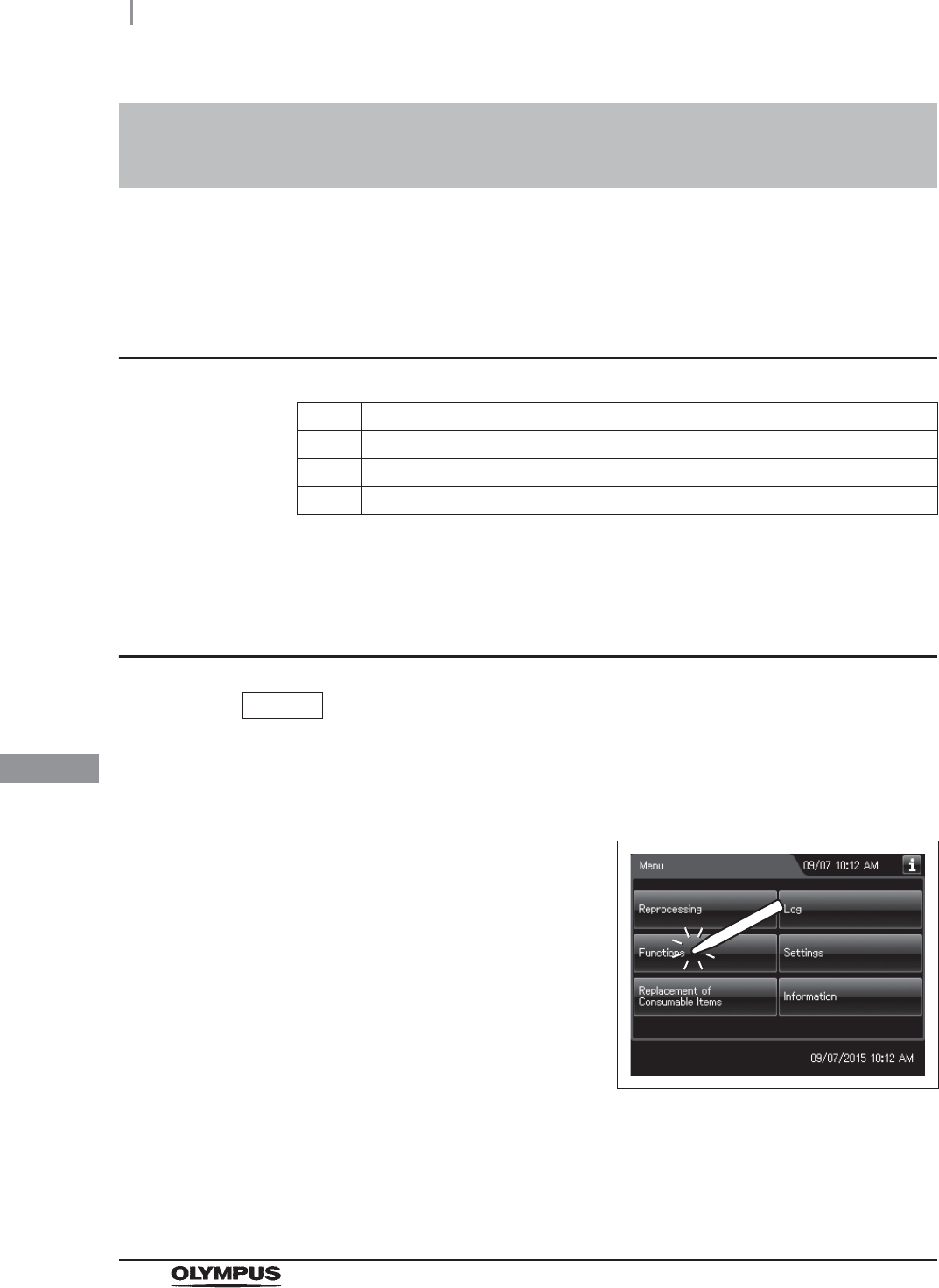
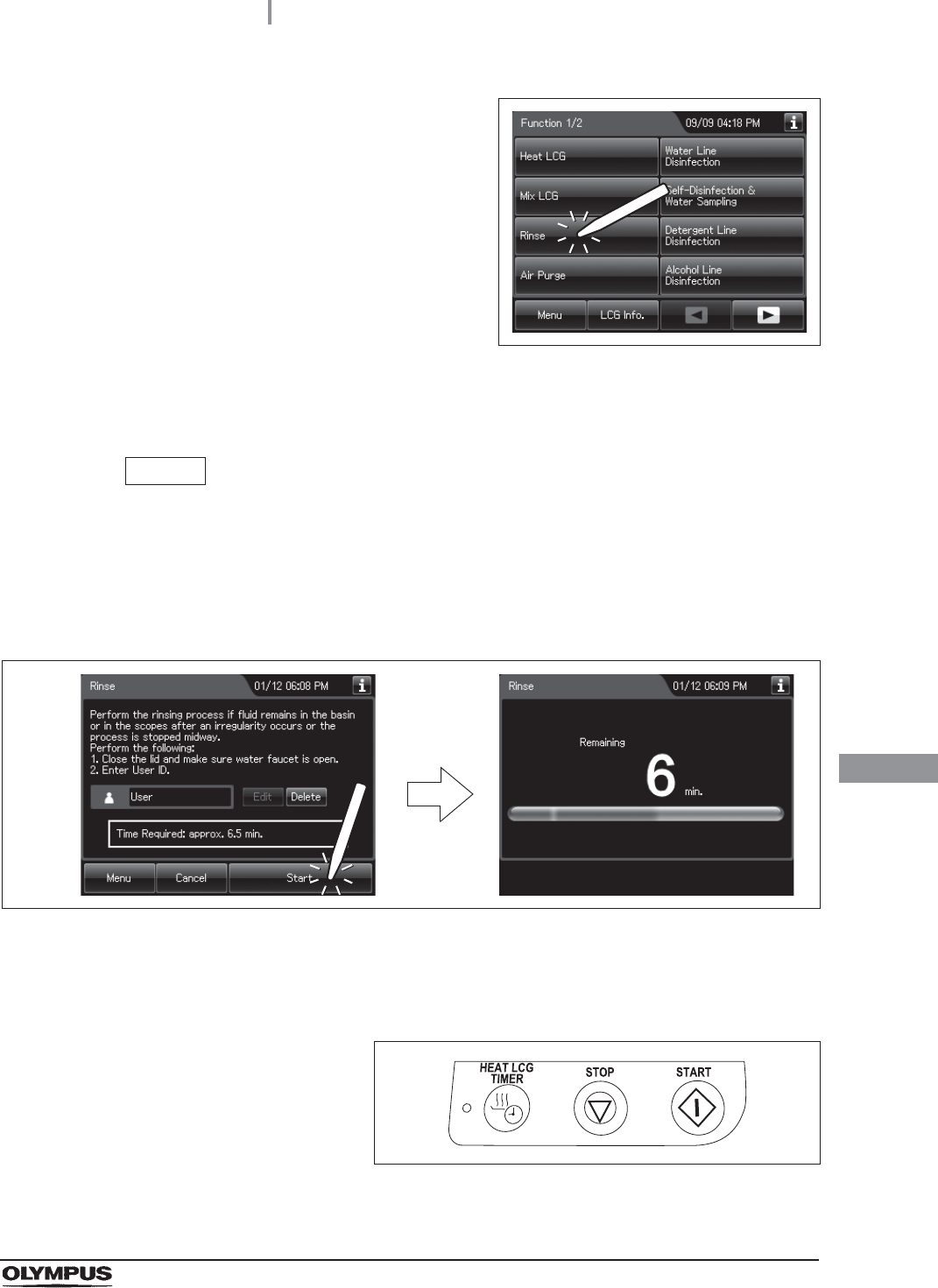
2Press the “Functions” button on the Menu
screen.
Figure 9.5
9.7 Cleaning the mesh filter in the water supply hose connector
431
OER-Elite OPERATION MANUAL
Ch.9
3Press the “Rinse” button.
Figure 9.6
4Enter the operator's user ID. For the detailed procedures, refer to Section 3.6,
“Entering ID” (If applicable).
NOTE
• The input of the user ID can be omitted by modifying the user ID input setting. For
details, refer to Section 4.5, “User ID Setting”.
• If the “Delete” button is pressed, the entered ID can be deleted.
5Press the “Start” button to relieve the incoming water pressure.
Figure 9.7
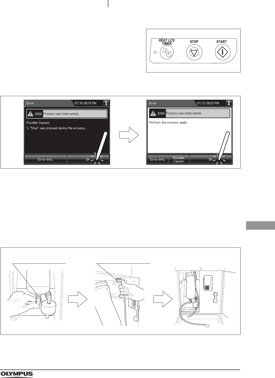
6After the pressure has been relieved (approximately 10 seconds), press the “STOP”
button on the control panel to stop the rinse. The touch screen displays the error code
[E000].
Figure 9.8
432
9.7 Cleaning the mesh filter in the water supply hose connector
OER-Elite OPERATION MANUAL
Ch.9
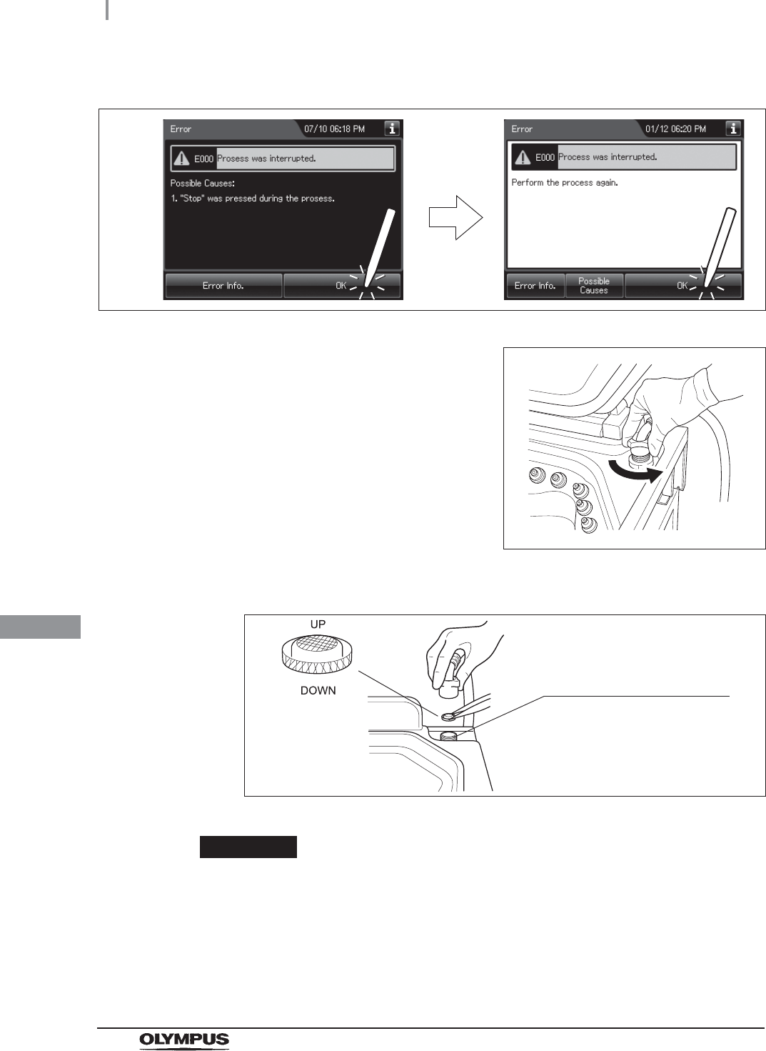
7Press the “OK” button repeatedly until the error screen is closed.
Figure 9.9
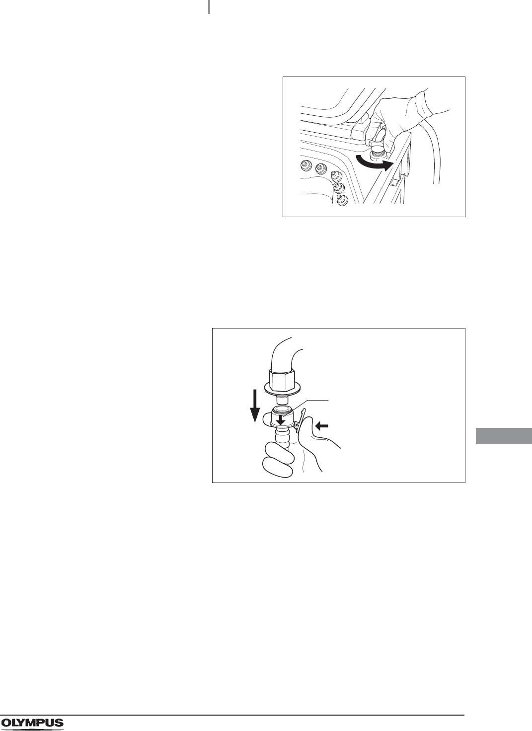
8Turn the connection ring on the reprocessor
side of the water supply hose in the direction
shown to disconnect the hose from the
reprocessor. If residual water is spilled from the
water supply hose, wipe it up with a clean cloth.
Figure 9.10
9Using clean tweezers, remove the mesh filter from the water supply hose connector.
Figure 9.11
CAUTION
Do not pinch the mesh filter in the water supply hose connector too hard. This
could deform the mesh filter or injure your fingers.
Water supply hose connector
9.7 Cleaning the mesh filter in the water supply hose connector
433
OER-Elite OPERATION MANUAL
Ch.9
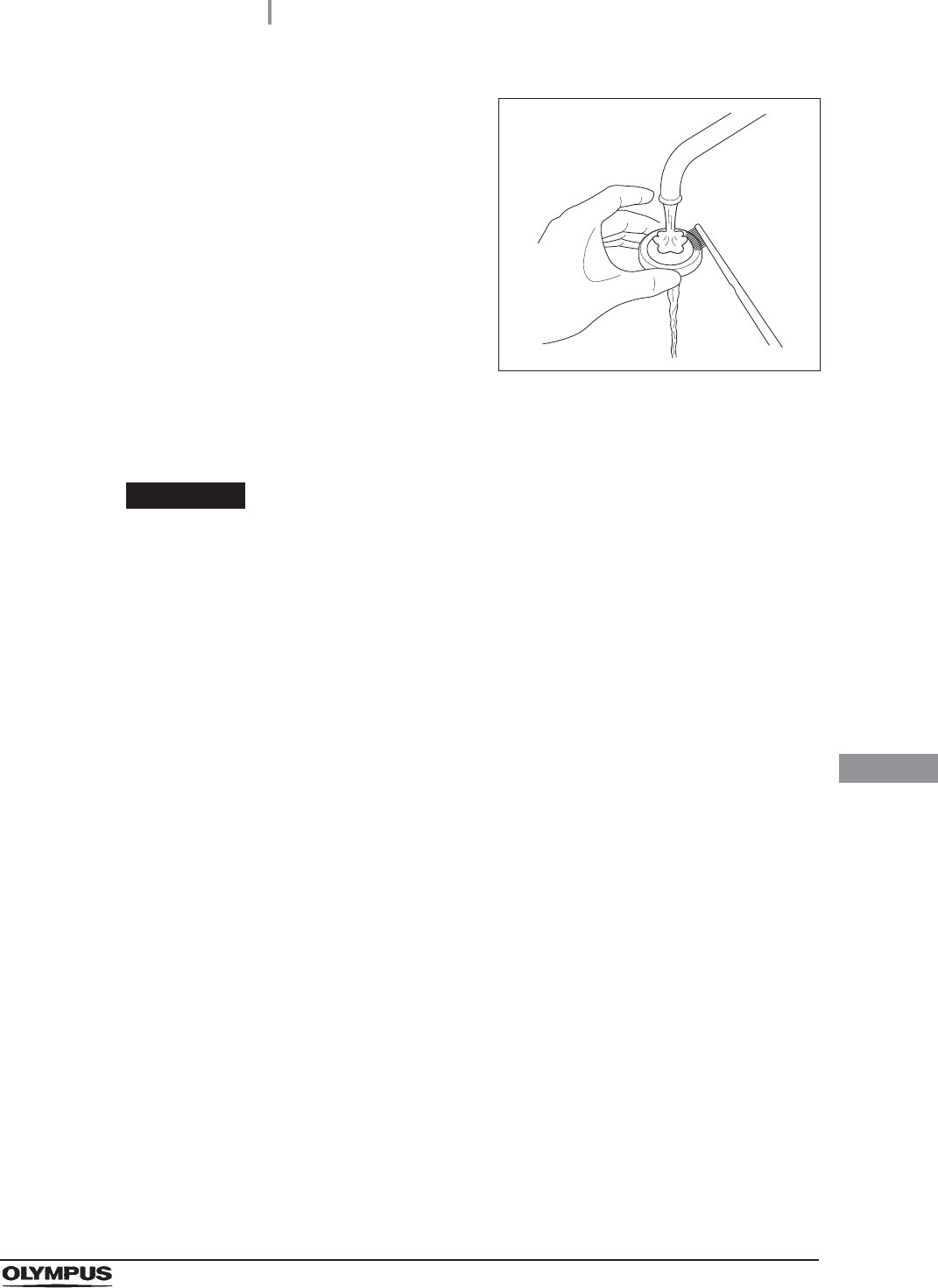
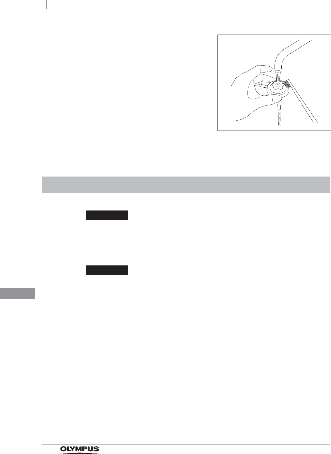
10 Clean the mesh filter in running water using a
brush.
Figure 9.12
11 Place the mesh filter in the original position in the water supply connector. Pay
attention to the up-down orientation.
CAUTION
Be sure to install the mesh filter in the water supply hose connector. Otherwise, dirt
and foreign matter in the water could enter the reprocessor and cause it to
malfunction.
12 Attach the connection ring of the water supply hose in the original position on the
reprocessor.
434
9.8 Replacing the fuse
OER-Elite OPERATION MANUAL
Ch.9
If the power switch does not turn on, replace the fuse with the following procedure.
WARNING
• Before removing the fuse box, be sure to set the power switch to OFF and unplug
the power cord from the connector on the reprocessor and the hospital-grade
power outlet. Otherwise, a fire or an electric shock may result.
• To prevent an electric shock, do not check or inspect the reprocessor with wet
hands.
9.8 Replacing the fuse
1Ensure that the power cord is connected securely to the connector on the reprocessor
and to the hospital-grade power outlet.
2Set the power switch to OFF and unplug the power cord from the hospital-grade
power outlet.
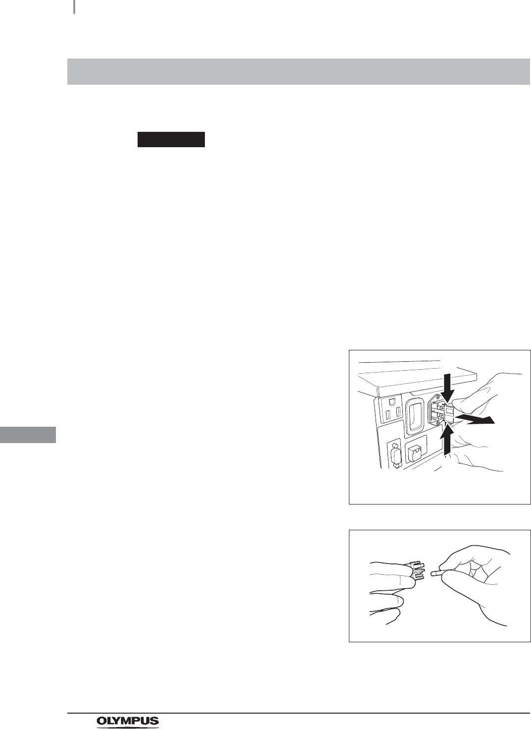
3Unplug the power cord from the power cord receptacle on the reprocessor.
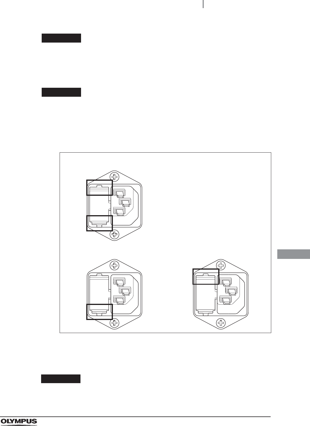
4Push the tabs on the fuse box in the directions
shown and take out the fuse holder
Figure 9.13
5Visually confirm that neither fuse is blown.
Figure 9.14
The numbers in the figure indicate the
fuse box removal sequence.
(1)
(2)
(1)
9.8 Replacing the fuse
435
OER-Elite OPERATION MANUAL
Ch.9
WARNING
If the power indicator does not light even after the fuses are replaced, be sure to
unplug the power cord from the power outlet. Otherwise, an electric shock may
result.
WARNING
Always use the fuses specified below. Otherwise, malfunction or failure of the
reprocessor may cause a fire or an electric shock.
Spare fuses: DB181500
CAUTION
If the power indicator does not light even when neither fuse is blown or after the
fuses are replaced, contact Olympus.
6Push the fuse holder into the reprocessor until it clicks. Confirm that the fuse holder is
fitted firmly into the reprocessor body.
Figure 9.15
7Connect the power cord, set the power switch to ON and confirm that the power
indicator lights up.
The fuse holder is properly installed
(Both the top and bottom projections touch the surface of the fuse holder cavity)
The fuse holder is not properly installed
(Both the top and bottom projections do not touch the surface of the fuse holder
cavity)

436
9.9 Preparing the reprocessor for long-term storage
OER-Elite OPERATION MANUAL
Ch.9
When the reprocessor will be stored for more than 14 days, follow the procedure described in this
section.
WARNING
• When handling the disinfectant solution and detergent and alcohol, carefully read
the cautions for its use to fully understand the given information and use as
instructed. Understanding the measures to be taken if the disinfectant solution
comes into contact with your skin and eyes is of paramount importance.
• When handling the disinfectant solution and detergent/alcohol, wear appropriate
personal protective equipment to avoid direct contact with your skin and eyes or
excessive inhalation of its vapor. The disinfectant solution and its vapor may have
effects on the human body. Personal protective equipment, such as goggles, face
mask, moisture-resistant clothing, and chemical-resistant gloves that fit properly
and are long enough so that your skin and eyes is not exposed. All personal
protective equipment should be inspected before use and replaced periodically
before it is damaged.
CAUTION
• Do not tilt the detergent tank while there is still detergent inside. If detergent is
spilled on the tray, it could damage the reprocessor.
• Do not tilt the alcohol tank while there is still alcohol inside. If alcohol is spilled on
the tray, it could damage the reprocessor.
9.9 Preparing the reprocessor for long-term storage
9.9 Preparing the reprocessor for long-term storage
437
OER-Elite OPERATION MANUAL
Ch.9
Workflow of Preparing the reprocessor for long-term
storage
Required items
Table 9 . 6
1
Suction the disinfectant solution from disinfectant solution
nozzle.
on page 438
2Suction the detergent solution from detergent nozzle inside.
on page 440
3Empty the detergent/alcohol tank.
on page 443
4Empty the water filter.
on page 445
5Remove the water supply hose.
on page 447
Check Required items
Syringe and tube
Connector jigs
70% ethyl alcohol or 70% isopropyl alcohol
Beaker (small) with a capacity of about 200 ml, such as a beaker
Provided wrench
Clean cloth
Sterile water: more than 50 ml
Filter tube (× 2)
Container with 2 L or larger capacity (wide-mouthed container such as a vat)
438
9.9 Preparing the reprocessor for long-term storage
OER-Elite OPERATION MANUAL
Ch.9
Preparing the reprocessor for long-term storage
1Discharge disinfectant solution from the reprocessor as described in “Draining the
disinfectant solution” on page 342.
2Step on the foot pedal to open the lid.
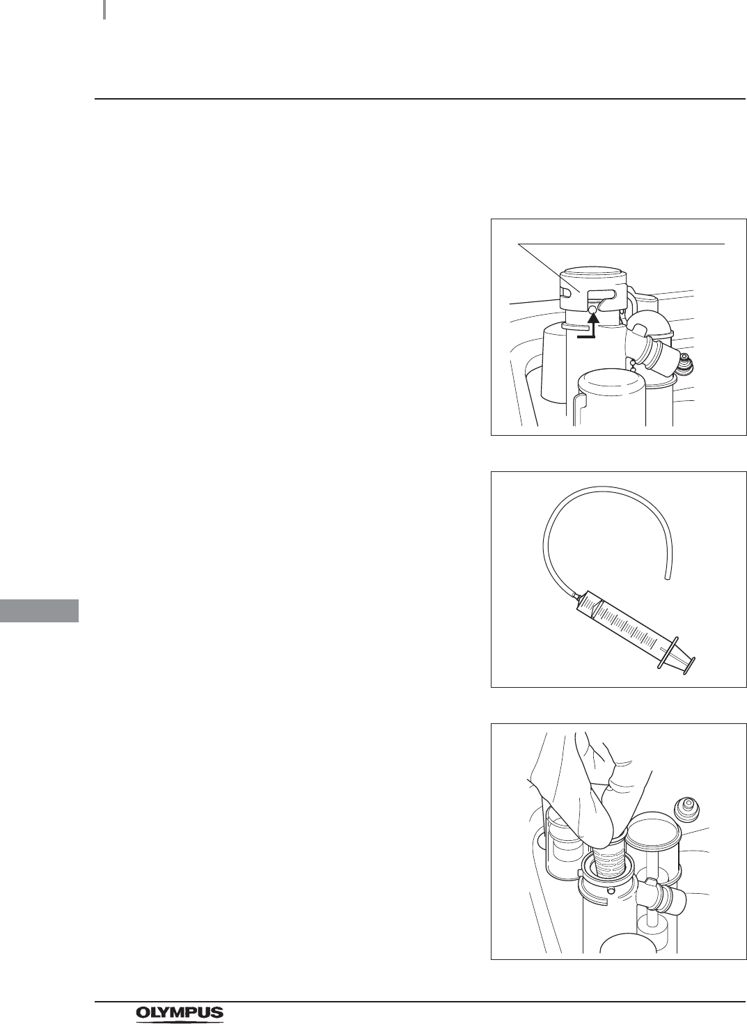
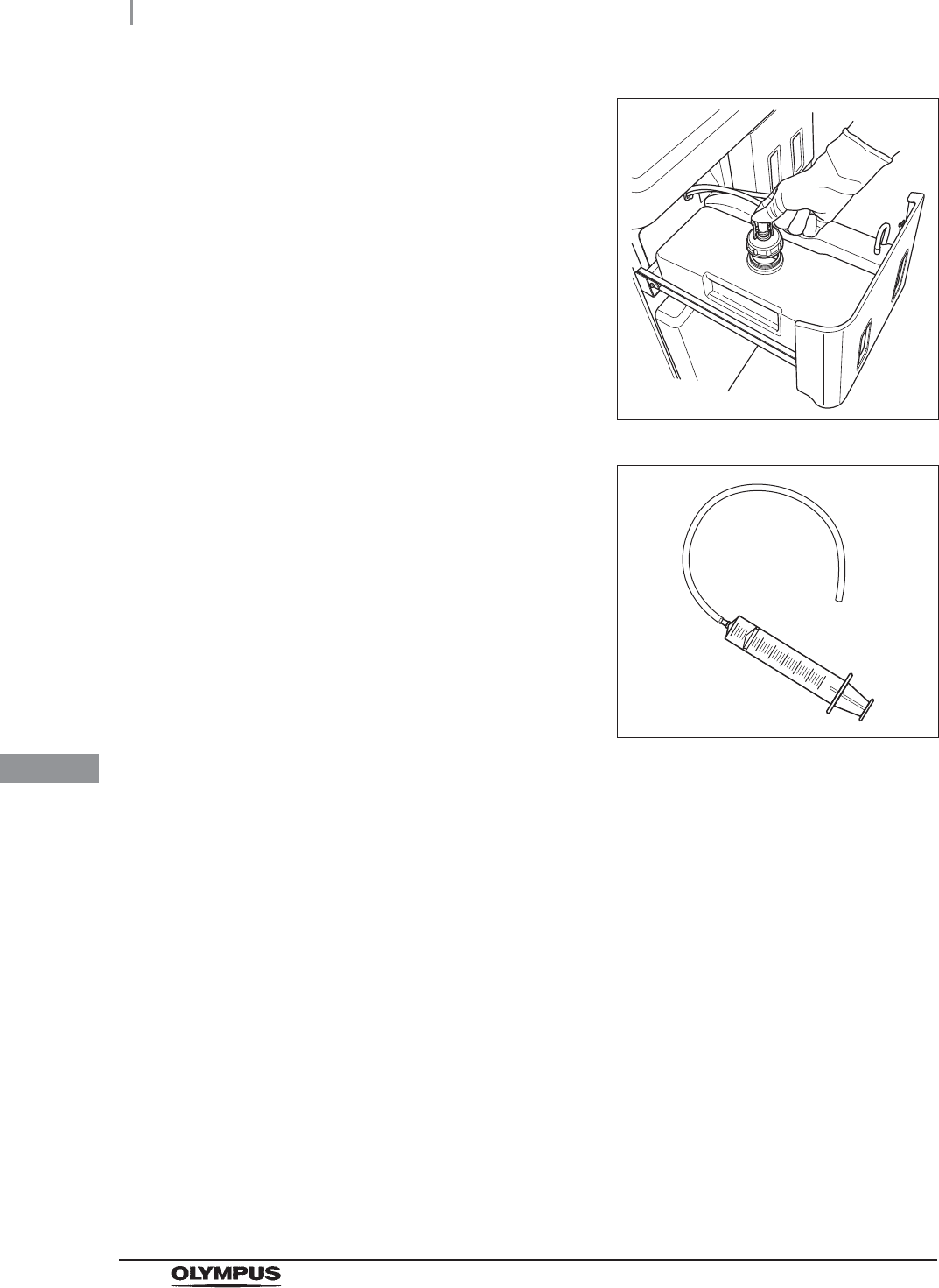
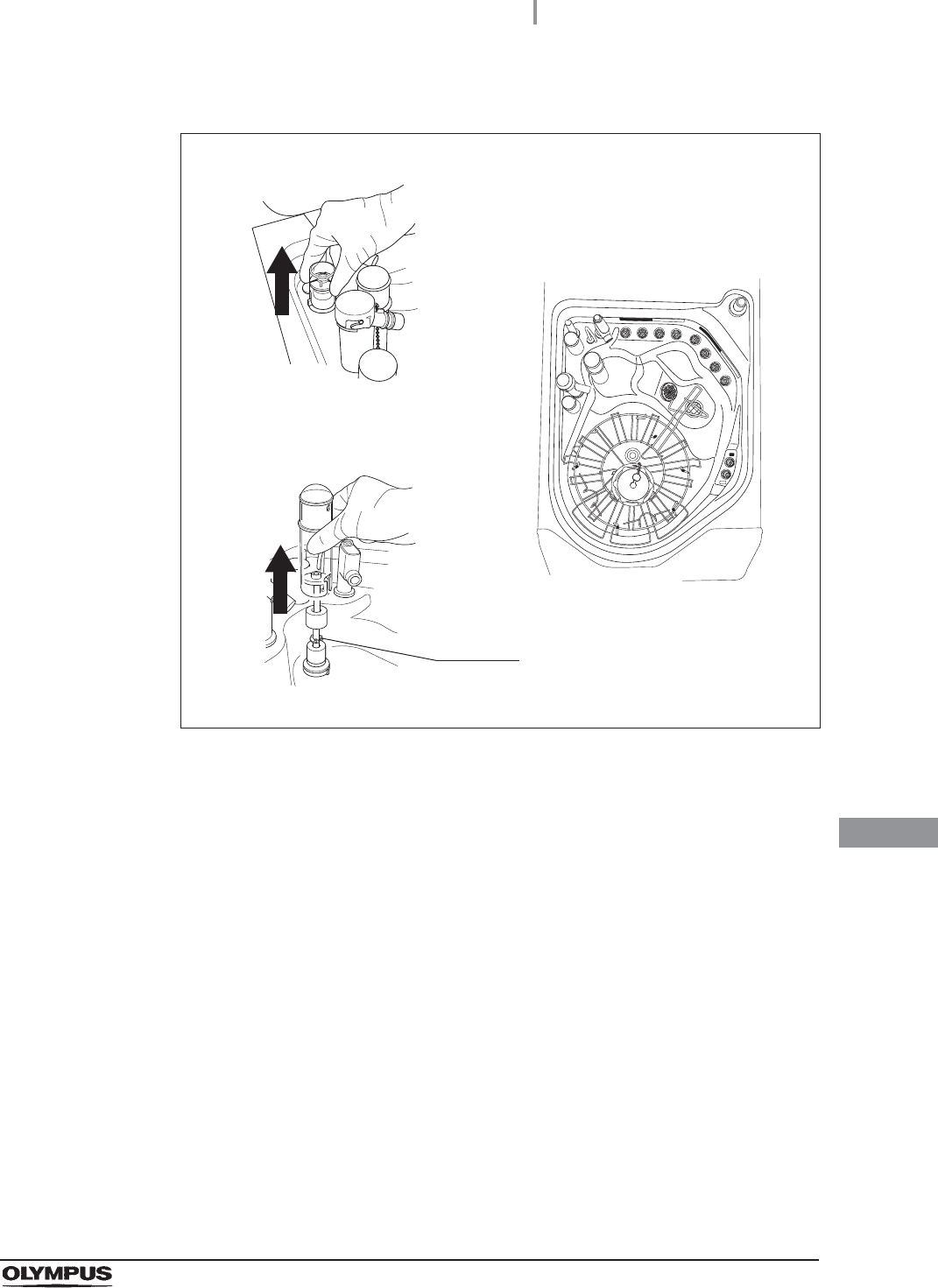
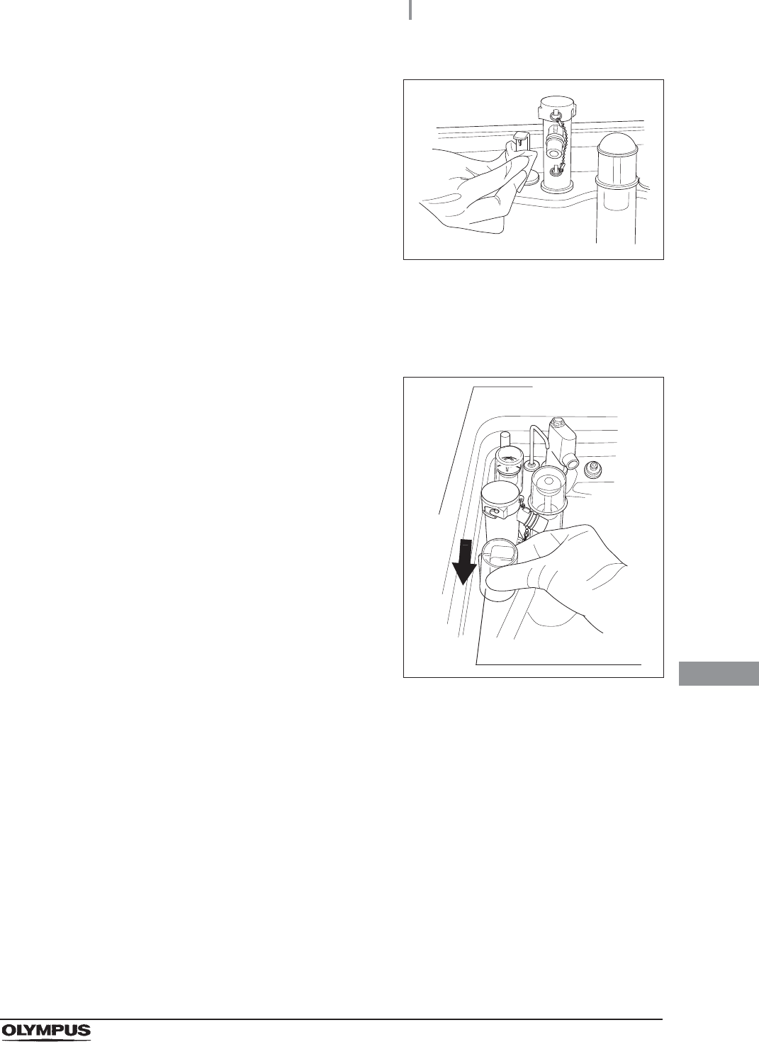
3Uncap the disinfectant solution nozzle of the
reprocessing basin by turning the disinfectant
solution nozzle cap. Refer to the Figure 9.16.
Figure 9.16
4Connect the provided syringe and tube.
Figure 9.17
5Remove the disinfectant solution nozzle filter
from the disinfectant solution nozzle.
Figure 9.18
Disinfectant solution nozzle cap
9.9 Preparing the reprocessor for long-term storage
439
OER-Elite OPERATION MANUAL
Ch.9
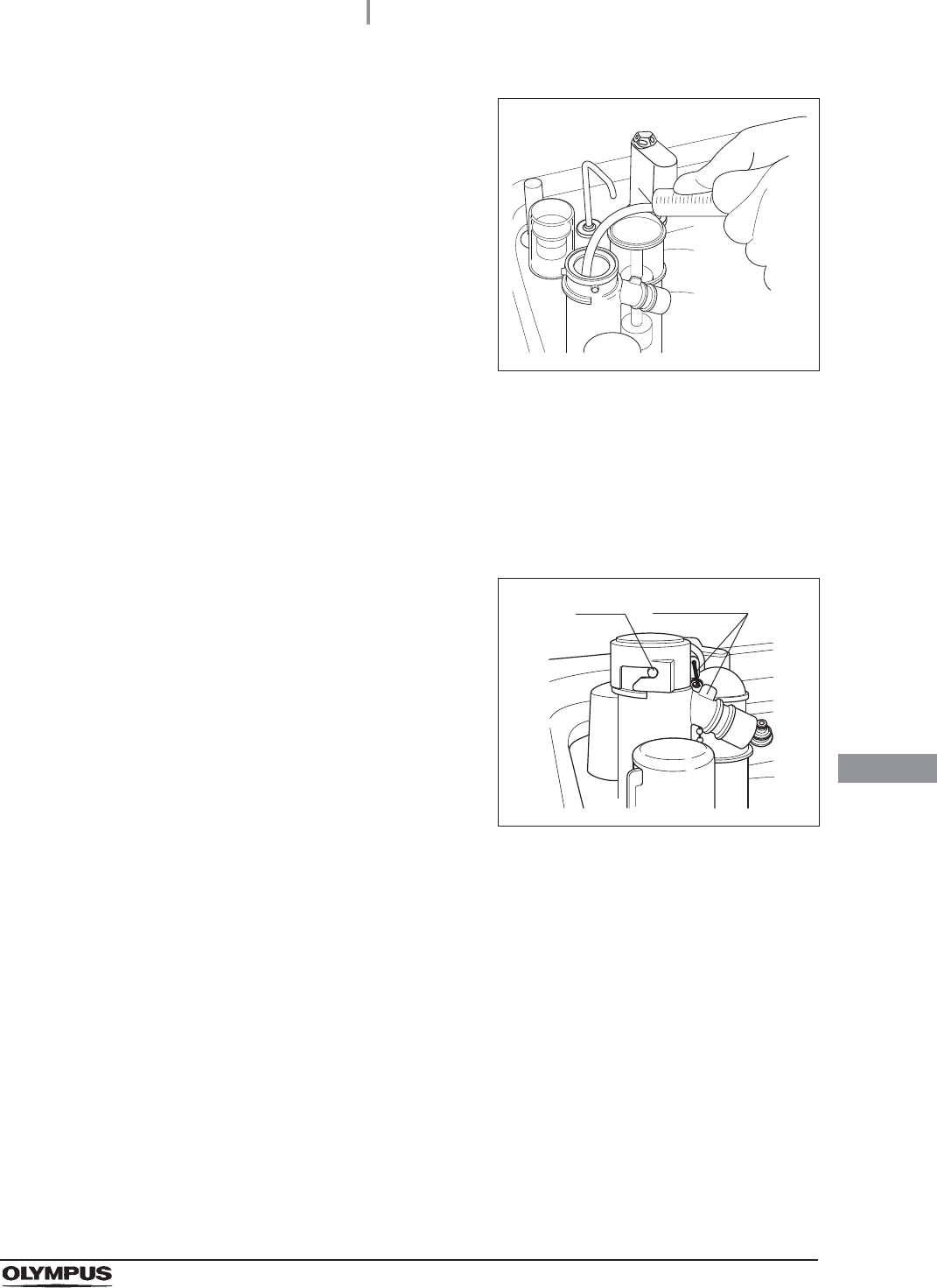
6Insert the tube attached to the syringe deeply
enough into the disinfectant solution nozzle.
Figure 9.19
7Suction the disinfectant solution with the syringe until no more disinfectant solution
comes out of the disinfectant solution nozzle.
8Remove the tube from the disinfectant solution nozzle.
9Dip alcohol to the O-ring of disinfectant solution nozzle filter, be sure to attach into the
disinfectant solution nozzle.
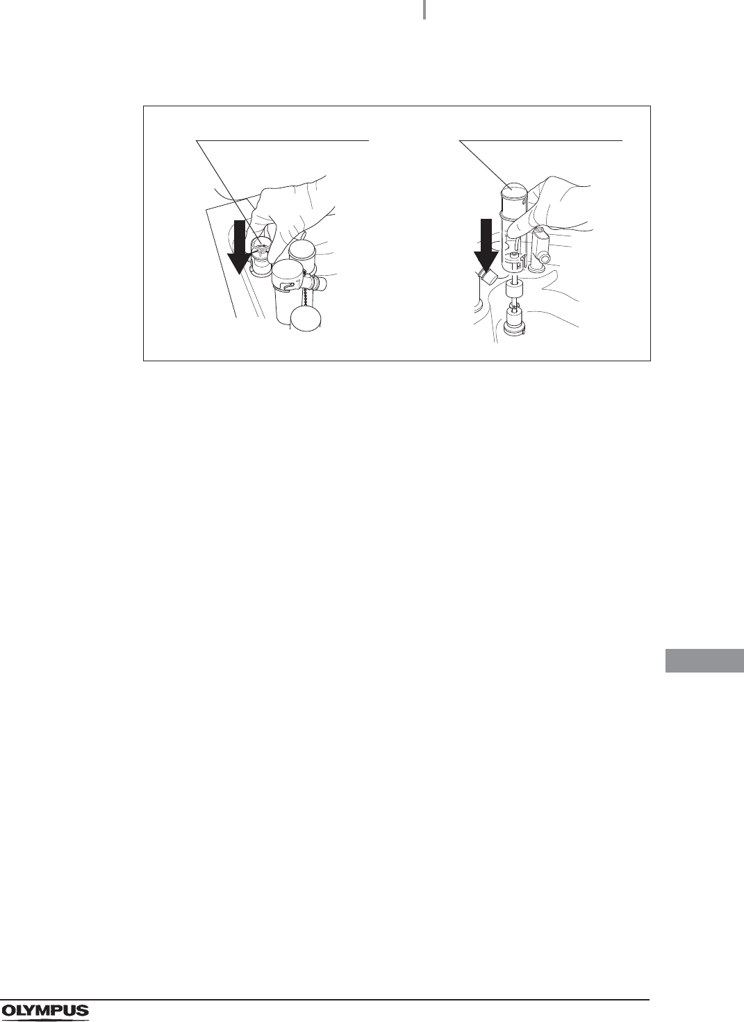
10 Attach the disinfectant solution nozzle cap to
the original position above the disinfectant
solution nozzle. Make sure that the pin returns
to the original position, and the projection of the
disinfectant solution nozzle cap is aligned to the
projection of the disinfectant solution nozzle.
Figure 9.20
11 Drain the disinfectant solution from syringe.
12 Pull out the detergent/alcohol drawer.
Pin projection
440
9.9 Preparing the reprocessor for long-term storage
OER-Elite OPERATION MANUAL
Ch.9
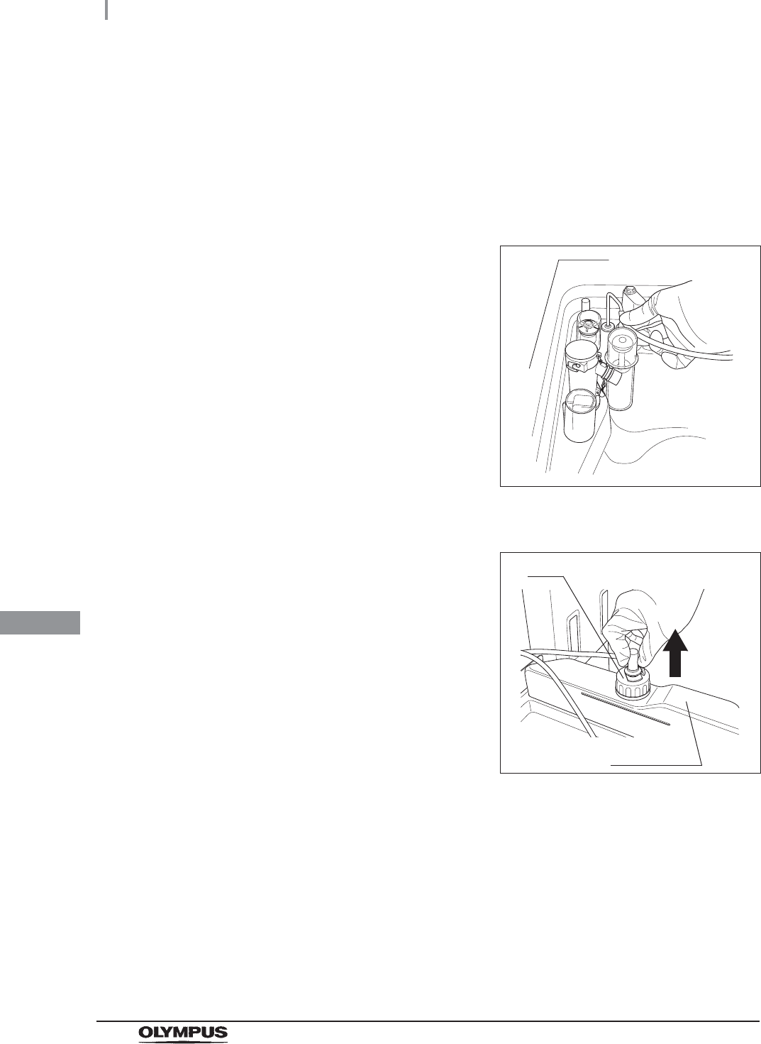
13 Turn the detergent tank cap to remove it. (Do
not disconnect the connector.)
Figure 9.21
14 Connect the provided syringe and tube.
Figure 9.22
15 Connect the tube attached to the syringe to the detergent nozzle inside the
reprocessing basin.
9.9 Preparing the reprocessor for long-term storage
441
OER-Elite OPERATION MANUAL
Ch.9
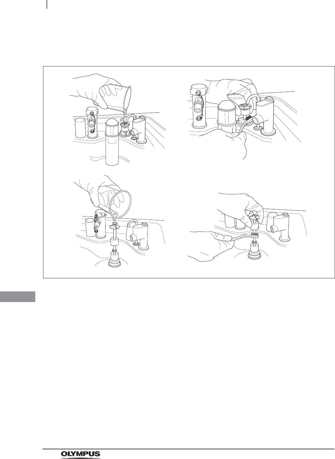
16 To remove detergent from inside the detergent line, connect the tube attached to the
syringe to the detergent nozzle inside the reprocessing basin. Suction the detergent
with the syringe until no more detergent comes out of the line.
Figure 9.23
17 Prepare a container or similar beaker and pour more than 50 ml of the sterile water
into it.
18 Put the cap and uptake tube in the beaker filled
with the sterile water.
Figure 9.24
19 To rinse the line with water, connect the tube attached to the syringe to the detergent
nozzle and suction more than 50 ml of sterile water with the syringe. (See
Figure 9.23)
20 To remove rinse water from inside the line, connect the tube attached to the syringe to
the detergent nozzle inside the reprocessing basin. Suction the water with the syringe
until no more water comes out of the line. (See Figure 9.23)
21 Prepare a container or similar beaker and pour about 50 ml of the 70% ethyl alcohol
or 70% isopropyl alcohol into it.
22 Put the detached cap and the uptake tube in the beaker of the 70% ethyl alcohol or
70% isopropyl alcohol. (See Figure 9.24)
442
9.9 Preparing the reprocessor for long-term storage
OER-Elite OPERATION MANUAL
Ch.9
23 To rinse the line with alcohol, connect the tube attached to the syringe to the
detergent nozzle and suction more than 50 ml of 70% ethyl alcohol or 70% isopropyl
alcohol with the syringe. (See Figure 9.23)
24 To remove 70% ethyl alcohol or 70% isopropyl alcohol from inside the line, connect
the tube attached to the syringe to the detergent nozzle inside the reprocessing basin.
Suction the alcohol with the syringe until no more alcohol comes out of the line. (See
Figure 9.23)
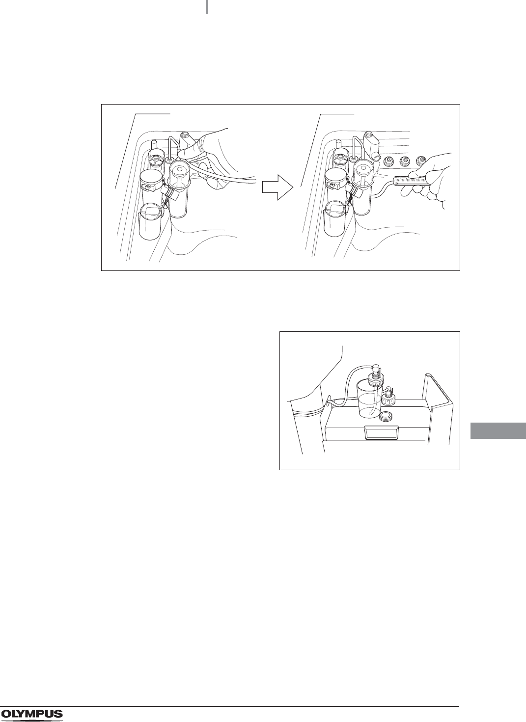
25 Remove the tube from the detergent nozzle.
Figure 9.25
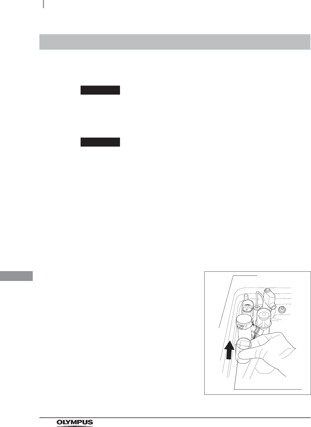
26 Remove the detergent tank.
27 To disconnect the tube connected to the
alcohol tank cap, push and hold the lock lever
on the connector and pull the tube.
Figure 9.26
28 Take the alcohol tank out of the reprocessor.
Cap
Alcohol tank
9.9 Preparing the reprocessor for long-term storage
443
OER-Elite OPERATION MANUAL
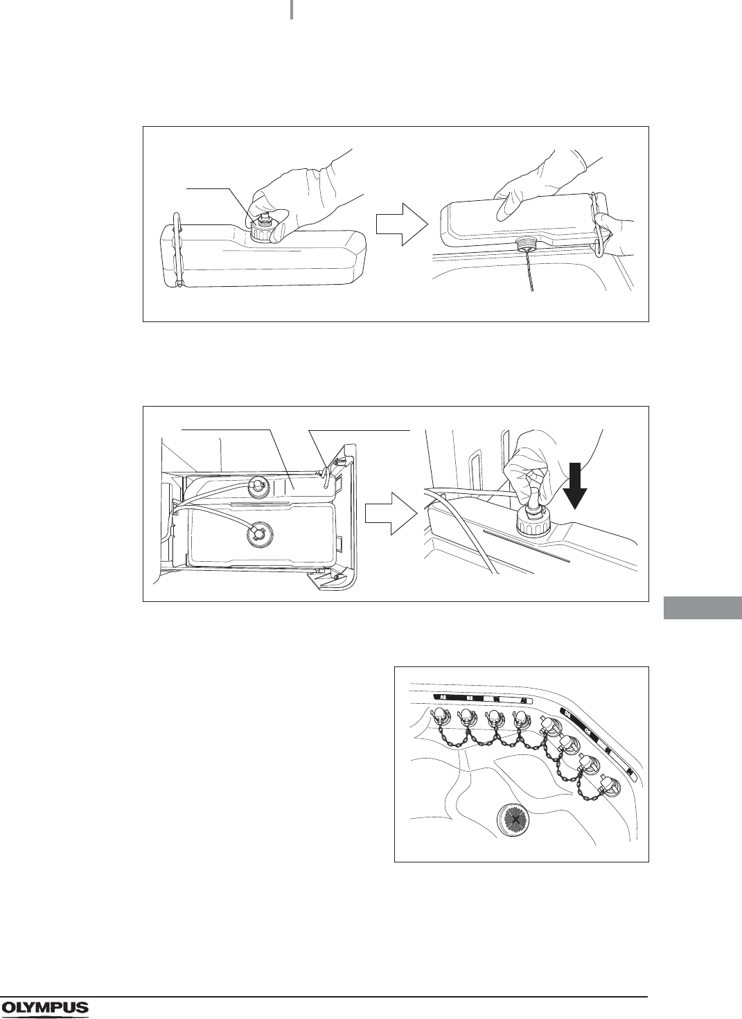
Ch.9
29 Turn the alcohol tank cap to remove it, empty the alcohol from the tank and dry the
inside.
Figure 9.27
30 Put the cap back on the tank, place the tank on the detergent/alcohol drawer, and
connect the tube to the cap again.
Figure 9.28
31 Close the detergent/alcohol drawer.
32 Attach the connector jigs to the connectors on
the reprocessing basin.
Figure 9.29
33 Close the lid by pushing until it clicks.
34 Perform the operation described in Section 7.6, “Air purge”.
35 Close the water faucet.
Cap
Alcohol tank Ventilation tube
444
9.9 Preparing the reprocessor for long-term storage
OER-Elite OPERATION MANUAL
Ch.9
36 Press the “Function” button on the Menu
Screen.
Figure 9.30
37 Press the “Rinse” button.
Figure 9.31
38 Enter the operator's user ID. For the detailed procedures, refer to Section 3.6,
“Entering ID” (If applicable).
NOTE
• The input of the user ID can be omitted by modifying the user ID input setting. For
details, refer to Section 4.5, “User ID Setting”.
• If the “Delete” button is pressed, the entered ID can be deleted.
39 Press the “Start” button to relieve the incoming water pressure.
Figure 9.32
9.9 Preparing the reprocessor for long-term storage
445
OER-Elite OPERATION MANUAL
Ch.9
40 Press the “STOP” button on the control panel to
stop the rinse. The touch screen displays the
error code [E000].
Figure 9.33
41 Press the “OK” button repeatedly until the error screen is closed.
Figure 9.34
42 Open the front door of the reprocessor.
43 Place a container with a capacity of 2 L or more in front of the reprocessor.
44 Put the tube-side ends of the two filter tubes in the container placed above.
45 Insert the connector ends of the two filter tubes into the connector below the water
filter housing and the connector above the water filter housing until they click. Water
will start to flow from the tube connected to the connector below the water filter
housing.
Figure 9.35
Connector below water
filter housing
Connector above water
filter housing
446
9.9 Preparing the reprocessor for long-term storage
OER-Elite OPERATION MANUAL
Ch.9
46 Press the “Air Purge” button on the first page of
the Function menu.
Figure 9.36
47 Hold the scope ID master card to the RFID reader of the reprocessor, and scan the
tag with the reader until a short beep (If applicable).
48 Press the “Start” button to start the air purge.
Figure 9.37
49 When the water flow stops, press the “Stop” button on the touch screen to end the air
purge process, and disconnect the two filter tubes by pushing the lock levers on their
connectors.
Figure 9.38
50 Step on the foot pedal to open the lid, disconnect the connector jigs, dry them
thoroughly, and store them in a clean place.
9.9 Preparing the reprocessor for long-term storage
447
OER-Elite OPERATION MANUAL
Ch.9
51 Press the power switch to set it to OFF.
52 Turn the connection ring on the reprocessor
side of the water supply hose in the direction
shown to disconnect the hose from the
reprocessor. If residual water spills from the
water supply hose, wipe it up with a clean cloth.
Figure 9.39
53 Put the reprocessor-side end of the hose in the wide-mouthed container to collect any
residual water that may flow from the water supply hose.
54 While holding the lock lever of the water supply socket of the water supply hose, pull
the sleeve toward the hose to disconnect the water supply socket from the water
faucet.
Figure 9.40
55 Step on the foot pedal to open the lid, dry the reprocessing basin thoroughly so that
no bacterial growth will occur inside it, and then close the lid by pushing until it clicks.
56 Disconnect the power cord plug from the hospital-grade power outlet.
(1)
The numbers in the figure
indicate the sequence for
disconnecting the water
supply socket.
(2)
(3)

448
9.10 Care and maintenance after long-term storage
OER-Elite OPERATION MANUAL
Ch.9
When using the reprocessor after it has been stored for more than 14 days without being used, setting
up the reprocessor, performing the reprocessing program, and performing the water supply piping
disinfection are required. Perform the following procedure.
Setting up the reprocessor
Performing the reprocess program
9.10 Care and maintenance after long-term storage
1Connect the water supply hose. For detailed instruction, refer to Section 4.4,
“Connection of the water supply hose” in “Instructions-Installation Manual”.
2Connect the power cord. For detailed instruction, refer to Section 4.6, “Connection of
the power supply” in “Instructions-Installation Manual”.
3Confirm the power supply. For detailed instruction, refer to Section 4.7, “Confirmation
of power to unit” in “Instructions-Installation Manual”.
4Install the detergent tank. For detailed instruction, refer to Section 4.18, “Installation of
the detergent tank” in “Instructions-Installation Manual”.
5Add alcohol into the alcohol tank. For detailed instruction, refer to Section 4.17,
“Addition of alcohol” in “Instructions-Installation Manual”.
6Replace the water filter (MAJ-824 or MAJ-2318). For detailed instruction, refer to
“Replacing the water filter” on page 380.
7Set up the disinfectant solution. For detailed instruction, refer to “Load the
disinfectant solution” on page 354 in this manual.
8Inspect and clean all parts before use. For detailed instruction, refer to Chapter 5,
“Inspection and Preparation Before Use” in this manual.
9Perform Self-Disinfection. For detailed instruction, refer to Section 4.20, “Checking
the functions” in “Instructions-Installation Manual”.

9.10 Care and maintenance after long-term storage
449
OER-Elite OPERATION MANUAL
Ch.9
Performing the water supply piping disinfection
NOTE
Be sure to perform routine maintenance as required depending on the length of
unused time. Otherwise, this reprocessor may cease to operate and/or perform as
expected. For details on routine maintenance, refer to Chapter 9, “Routine
Maintenance”.
10 Olympus recommends performing microbiological sampling of the OER-Elite rinse
water quality right after performing the water supply piping disinfection. For details on
sampling rinse water, refer to Section 7.8, “Self-disinfection and water sampling”.

450
9.10 Care and maintenance after long-term storage
OER-Elite OPERATION MANUAL
Ch.9
10.1 Inspection at the end of every working day
451
OER-Elite OPERATION MANUAL
Ch.10
Chapter 10 End-of-Day Checks
Inspect and clean all parts of the reprocessor regularly to ensure safe and reliable operation.
The Heat LCG Timer should be activated after completing the inspections and cleaning described in
this section.
Table 1 0 . 1
Table 1 0 . 2
WARNING
• Be sure to inspect and clean the reprocessor as described in this chapter.
Otherwise, the functions and performance of the reprocessor may not operate
properly.
• If any irregularity is found, do not use the reprocessor and contact Olympus. If the
reprocessor is used when an irregularity is found, the reprocessor may malfunction.
Water leakage, electric shock, burns, and/or fire may also result.
• When inspecting the reprocessor, always wear appropriate personal protective
equipment, such as eyewear, face mask, moisture-resistant clothing, and
chemical-resistant gloves that fit properly and are long enough so that your skin
and eyes is not exposed. All personal protective equipment should be inspected
before use and replaced periodically before it is damaged.
10.1 Inspection at the end of every working day
Check Checks at the end of every working day
Section 10.2, “Turning the power OFF and closing the water faucet”
Section 10.3, “Cleaning the mesh filters”
Section 10.4, “Cleaning the float switches”
Section 10.5, “Cleaning the fluid level sensor”
Section 10.6, “Cleaning the stylus pen”
If the stylus pen is reprocessed in every reprocessing cycle, it has not to be
cleaned at the end of every work day.
Section 10.7, “Cleaning the outer surface”
Check Required items
70% ethyl alcohol or 70% isopropyl alcohol
Clean cloth (Should clean up the Touch screen or any panel by using the lint-free
clean cloth.)
Filter cleaning brush
Neutral detergent
Sterile gauze
452
10.2 Turning the power OFF and closing the water faucet
OER-Elite OPERATION MANUAL
Ch.10
WARNING
• To prevent water leakage, be sure to close the water faucet at the end of the
working day.
• After using the reprocessor, dry it thoroughly (so that no water remains in the
reprocessing basin) and close the lid before storage. Otherwise, microorganisms
may proliferate in the reprocessor.
• If the reprocessor has been stored after closing the lid without drying the
reprocessing basin completely, thoroughly wipe the inside of the reprocessing
basin with a cloth moistened with 70% ethyl alcohol or 70% isopropyl alcohol
before the next use.
10.2 Turning the power OFF and closing the water
faucet
1Close the water faucet.
2Make sure that the Heat LCG indicator is not lit.
NOTE
When the Heat LCG Timer indicator lights up, the Heat LCG Timer is set.
3Press the power switch to OFF. If the Heat LCG Timer indicator is lit, stop the Heat
LCG Timer and turn the reprocessor OFF.
4Step on the foot pedal to open the lid, let the inside of the reprocessing basin dry
completely (so that no water remains in the basin), and close the lid by pushing until it
clicks. If the lid is open, the Heat LCG Timer cannot perform.
10.3 Cleaning the mesh filters
453
OER-Elite OPERATION MANUAL
Ch.10
Clean the two circulation port mesh filters and the drain port mesh filter.
WARNING
A clogged mesh filter not only prevents the reprocessor from functioning properly,
but may also result in ineffective reprocessing.
CAUTION
• If the mesh filters have been removed, be sure to put them back in their original
positions before using the reprocessor. If you forget to attach the mesh filters, the
pump may malfunction and/or foreign matter might get into the OER-Elite piping or
endoscope nozzles and channels clog them.
• When cleaning the mesh filters, take care not to leave brush hair or cotton swab
fiber in the mesh. Otherwise, their filtering effectiveness may be reduced.
• If a mesh filter is dropped or subjected to an impact, make sure that the mesh
shape is not deformed. Otherwise, the filtering effect may degrade.
• Two mesh filters are installed on the outer and inner sides of the circulation port. Be
sure to remove, inspect, and clean both of them.
10.3 Cleaning the mesh filters
1Step on the foot pedal to open the lid.
2Remove the mesh filters from the reprocessing basin.
Figure 10.1
Drain port mesh filter
Circulation port
mesh filters
454
10.4 Cleaning the float switches
OER-Elite OPERATION MANUAL
Ch.10
WARNING
Take care not to damage the float switches when cleaning it. If the float switch is
damaged, it may not be able to correctly detect the fluid level and the endoscope
reprocessing may be insufficient.
CAUTION
• Always press the power switch OFF before cleaning the float switch. Moving the
float switch while the power switch is ON will be detected as an error by the
reprocessor and result in error processing.
• Do not disassemble components of float switch (e.g., stopper). Otherwise it may
not be able to detect the fluid correctly and the process may stop due to erroneous
error detection.
3Clean each mesh filter in running water using a
brush.
Figure 10.2
4Attach the mesh filters in their original positions.
10.4 Cleaning the float switches
1Make sure that the power switch is OFF.
10.4 Cleaning the float switches
455
OER-Elite OPERATION MANUAL
Ch.10
2Lift two float switch cover up to remove.
Figure 10.3
Float switch (long) cover
Float switch (short) cover
Stopper
456
10.4 Cleaning the float switches
OER-Elite OPERATION MANUAL
Ch.10
3While applying clean water to the float switches, clean the stem using brush. Move
the float up and down manually and thoroughly clean around the stem. Rinse the float
switches by pouring clean water over it.
Figure 10.4
4Dry around the float switches using a lint-free clean cloth.
5Clean two float switch covers in running water and dry.
10.4 Cleaning the float switches
457
OER-Elite OPERATION MANUAL
Ch.10
6Reinstall the float switch covers.
Figure 10.5
Float switch (short) cover Float switch (long) cover
458
10.5 Cleaning the fluid level sensor
OER-Elite OPERATION MANUAL
Ch.10
After using the reprocessor, clean the fluid level sensor to ensure correct detection of the fluid level in
the reprocessing basin.
WARNING
Take care not to damage the fluid level sensor when cleaning it. If the sensor is
damaged, it may not be able to correctly detect the fluid level and the endoscope
reprocessing may be insufficient.
CAUTION
• Do not use detergent to clean the fluid level sensor. If any detergent is left on the
sensor, it may not be able to correctly detect the fluid level and the cycle may stop
due to erroneous error detection.
• Be sure to completely dry the fluid level sensor. Otherwise, the sensor may not be
able to correctly detect the fluid level.
• Be sure to turn the reprocessor OFF before cleaning the fluid level sensor.
Otherwise, the reprocessor may malfunction.
• Be sure to reinstall the fluid level sensor covers to the fluid level sensor after
cleaning. Otherwise, the sensor may not be able to correctly detect the fluid level
and the reprocessor may malfunction.
10.5 Cleaning the fluid level sensor
1Press the power switch to OFF.
2Lift the fluid level sensor cover up to remove as
shown with the arrow in Figure 10.6.
Figure 10.6
Fluid level sensor cover
10.5 Cleaning the fluid level sensor
459
OER-Elite OPERATION MANUAL
Ch.10
3Clean the fluid level sensor using a lint-free
clean cloth moistened with 70% ethyl alcohol or
70% isopropyl alcohol.
Figure 10.7
4Dry around the fluid level sensor using a lint-free clean cloth.
5Clean the fluid level sensor cover in running water and then completely dry the cover
using a lint-free cloth.
6Reinstall the fluid level sensor cover.
Figure 10.8
Fluid level sensor cover
460
10.6 Cleaning the stylus pen
OER-Elite OPERATION MANUAL
Ch.10
Clean the stylus pen.
There are two methods to clean the stylus pen:
• Wipe the stylus pen with a cloth moistened with 70% ethyl alcohol or 70% isopropyl alcohol.
• Reprocess the stylus pen together with endoscopes with the reprocessor.
Wiping the stylus pen with alcohol
Wipe the stylus pen with a cloth moistened with 70% ethyl alcohol or 70% isopropyl alcohol.
Reprocessing together with endoscopes
Setting the stylus pen
10.6 Cleaning the stylus pen
1Set endoscopes and accessories in the reprocessing basin. For the detailed
procedures, refer to Section 6.6, “Loading of endoscopes and accessories”.
2Set the stylus pen by fitting the hole of the stylus pen around the Pin (Black marking
M4) of the retaining rack in the reprocessing basin.
Figure 10.9
Stylus pen
10.7 Cleaning the outer surface
461
OER-Elite OPERATION MANUAL
Ch.10
Reprocessing
Start the reprocessing process. For details, refer to Section 6.8, “Reprocessing”.
Removing the stylus pen
1Take the stylus pen out of the reprocessing basin. Dry using a piece of sterile gauze.
2Place the stylus pen in the stylus pen holder.
10.7 Cleaning the outer surface
1Using a clean cloth moistened with neutral
detergent, clean the following parts of the
reprocessor the front and back of the lid, the lid
packing, the edge and inside of the
reprocessing basin, the RFID reader, and the
control panel. After using the neutral detergent,
rinse them with clean cloth moistened with
clean water.
Figure 10.10
2Then wipe them with a dry clean cloth. To prevent growth of microorganisms, it is also
recommended to wipe those areas with a cloth moistened with 70% ethyl alcohol or
70% isopropyl alcohol and then air-dry the alcohol.
3After completing the alcohol wipe down close the lid by pushing until it clicks. If the
reprocessor has been stored with the lid closed without drying the reprocessing basin
completely, wipe the inside of the reprocessing basin with a cloth moistened with 70%
ethyl alcohol or 70% isopropyl alcohol completely before the next use.
4Step on the foot pedal to open the lid, let the inside of the reprocessing basin dry
completely (so that no water remains in the basin), and close the lid by pushing until it
clicks. If the lid is open, the Heat LCG Timer cannot perform.

462
10.7 Cleaning the outer surface
OER-Elite OPERATION MANUAL
Ch.10
WARNING
• Do not use the reprocessor if the lid or the lid packing seems to be damaged or
defective. Using the reprocessor when an irregularity has been detected may
interfere with reprocessing. Furthermore, fluid leakage may damage peripheral
devices or facilities near the equipment. If any irregularity is found with the lid or the
lid packing, contact Olympus.
• Do not remove the lid packing. Otherwise, disinfectant solution may leak and
damage for the reprocessor and areas near the equipment by reprocessing or
opening the lid.
• If replacement or adjustment of the lid packing is required, please contact Olympus.
Only Olympus-trained personnel are permitted to replace the lid packing or adjust
its position. Improper installation or positioning of the lid packing may result in
leakage of water, detergent solution, or disinfectant solution. This may result in
injury to personnel and/or damage to the reprocessor.

11.1 Log menu
463
OER-Elite OPERATION MANUAL
Ch.11
Chapter 11 Log Management
Records of reprocessing, functions, and replacement of consumable items can be displayed on the
touch screen, output to a portable memory, or printed out.
11.1 Log menu
No. Button Description
1 Display and Output button Press to perform log display and output. For details, refer to page 464.
2 Printout button Press to perform log printout. For details, refer to page 575.
3 Menu button Press to display the Menu screen.
4 LCG Info. button Press to display the LCG Info. screen.
1
2
3 4
464
11.2 Log display and output
OER-Elite OPERATION MANUAL
Ch.11
The records below can be displayed on the touch screen. Reprocessing records and Logs can be also
outputted to a portable memory.
Table 11.1
11.2 Log display and output
Record type Description
Reprocessing Records The record of reprocessing process, including errors.
Error Records The record of errors occurred in the reprocessor.
Leak Test Records The record of auto and manual leak tests performed on the reprocessor.
MRC Check Records The record of MRC check result.
LCG Replacement Records The record of replacements of the disinfectant solution.
Detergent Replacement Records The record of replacements of the detergent.
Water Filter Replacement Records The record of replacements of the water filter.
Air Filter Replacement Records The record of replacements of air filter.
Gas Filter (Lid) Replacement Records The record of replacements of the gas filter on the lid.
Gas Filter (Tank) Replacement
Records
The record of replacements of the gas filter on the disinfectant solution tank.
Water Line Disinfection Records The record of water supply line disinfections.
Self Disinfection & Water Sampling
Records
The record of rinse water collections.
Detergent Line Disinfection Records The record of detergent line disinfections.
Alcohol Line Disinfection Records The record of alcohol line disinfections.
Heat LCG Records The record of Heat LCG operations.
Mix LCG Records The record of disinfectant solution mixing process.
Rinse Records The record of rinse process.
Air Purge Records The record of air purge process.
Alcohol Flush Records The record of alcohol flush process.
Leaking Scope Decontamination
Records
The record of leaking scope decontamination process.
ALT Self-Check Records The record of self-check of the auto leak test function.
Periodic Maintenance and Repair
Records
The record of periodic maintenance and servicing operations.
Portable Memory Records The record of portable memory outputs.
11.2 Log display and output
465
OER-Elite OPERATION MANUAL
Ch.11
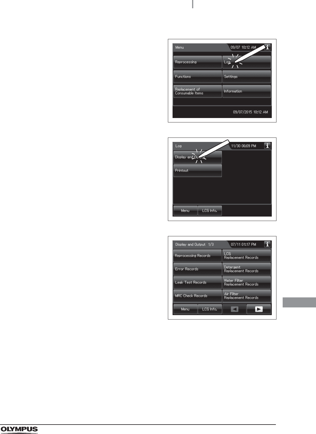
1Press the “Log” button on the Menu Screen.
Figure 11.1
2Press the Display and Output button.
Figure 11.2
3Select the type of the record to be displayed or
output to the portable memory by feeding
pages as required.
Figure 11.3

466
11.2 Log display and output
OER-Elite OPERATION MANUAL
Ch.11
4Press the Reprocessing Records button.
No. Button Description
1 Select Dates Press to specify the period that displays the records.
2 Select Month Press to specify the month that displays the records.
3 Data Since Last
Export
Press to display the records that have not been output to a portable memory.
4 All Records Press to display all records.
5 Menu Press to go to the Menu screen.
6 Cancel Press to returns to the previous screen.
5 6
1
2
3
4
11.2 Log display and output
467
OER-Elite OPERATION MANUAL
Ch.11
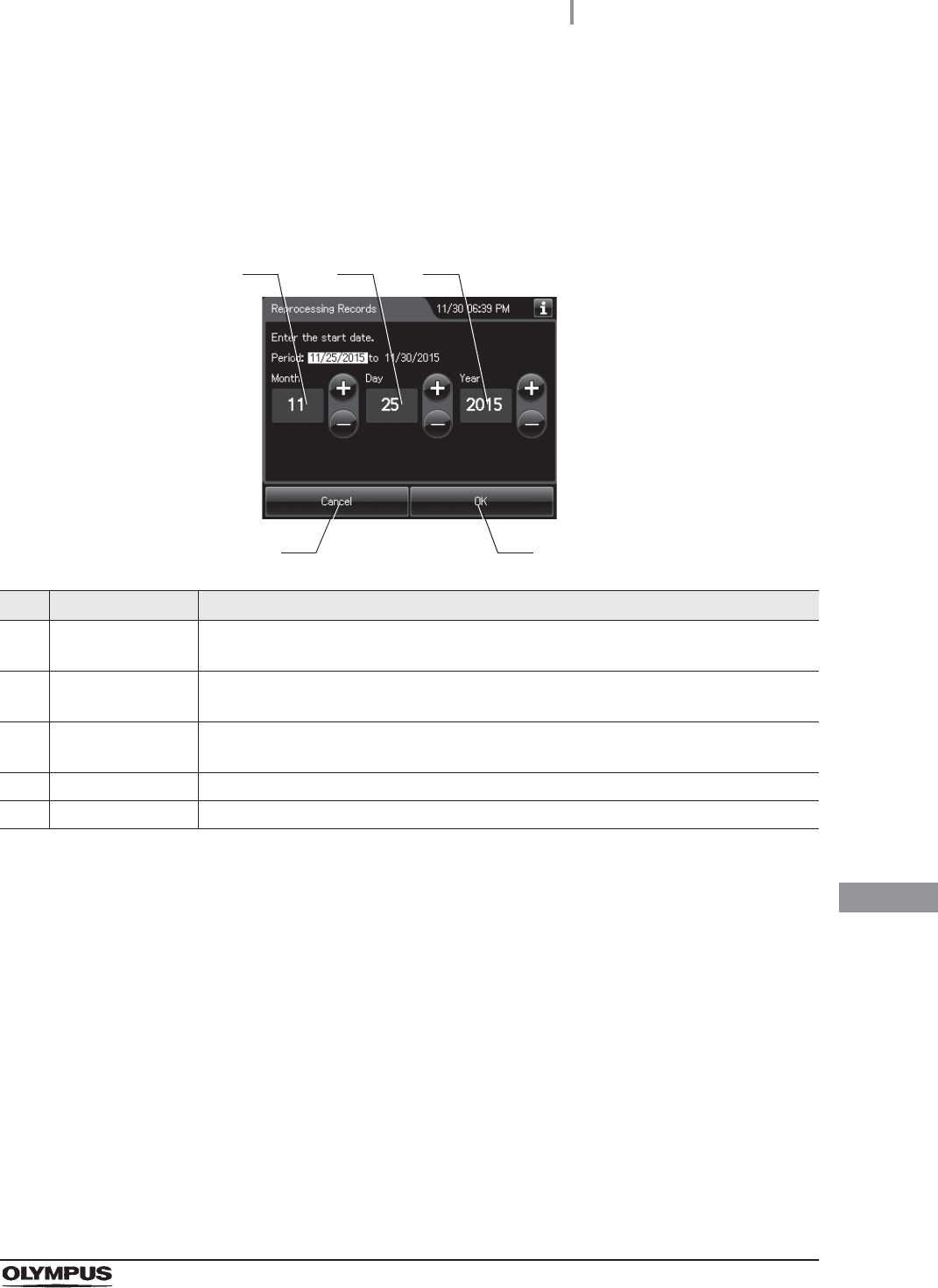
To display the records of “Select dates”:
1Press the “Select Dates” button.
2Enter the date of start of the period to be displayed. Press the “OK” button.
No. Item/Button Description
1 Month Set the month of the start date of the period to be viewed. Pressing the + button
increments the setting and pressing the – button decrements it.
2 Day Set the day of the start date of the period to be viewed. Pressing the + button increments
the setting and pressing the – button decrements it.
3 Year Set the year of the start date of the period to be viewed. Pressing the + button
increments the setting and pressing the – button decrements it.
4 Cancel Returns to the previous screen page.
5 OK Advances to the end date setting.
1
4 5
2 3
468
11.2 Log display and output
OER-Elite OPERATION MANUAL
Ch.11
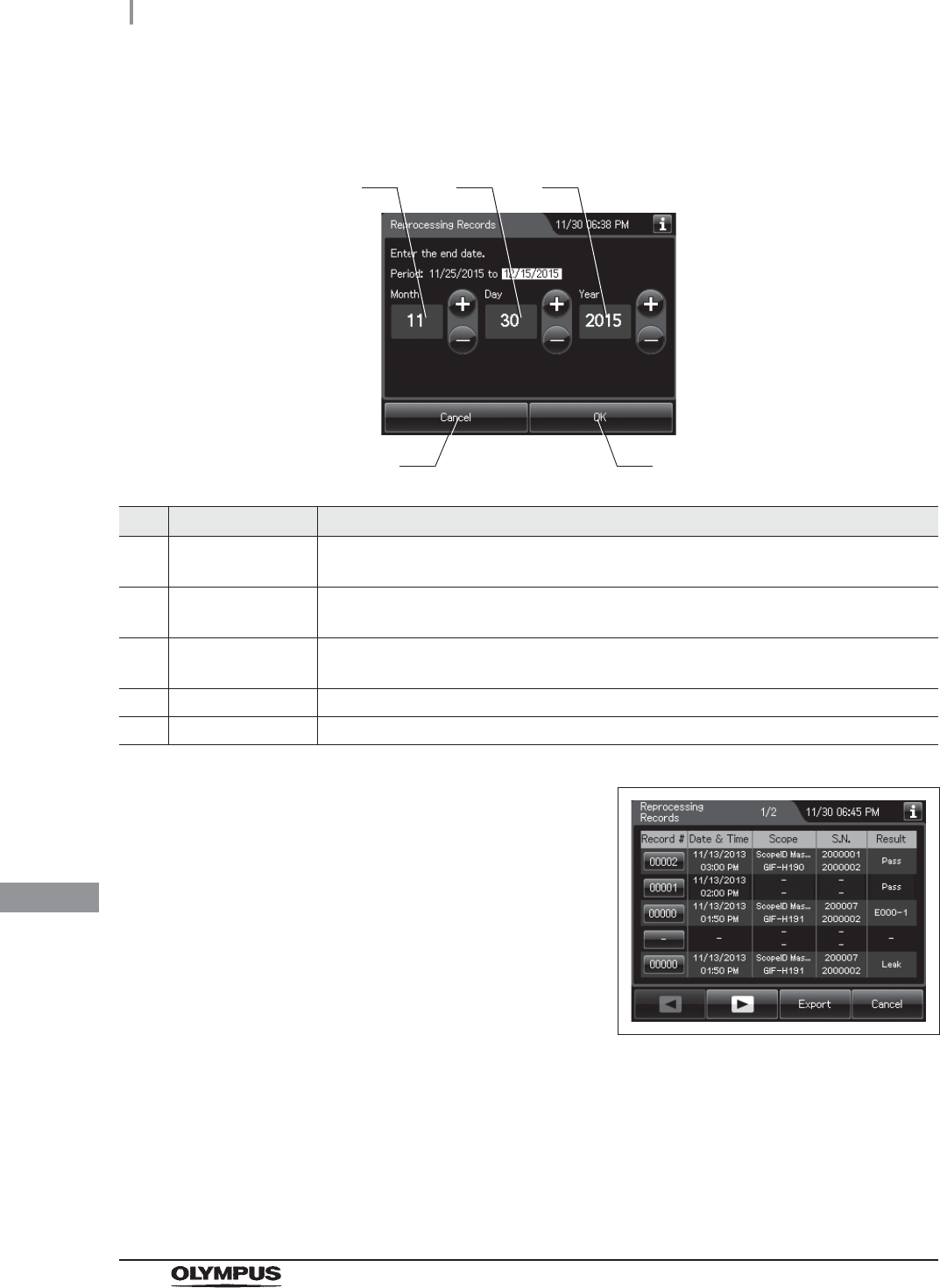
3Enter the end date of the desired period. Press the “OK” button.
No. Item/Button Description
1 Month Set the month of the start date of the period to be viewed. Pressing the + button
increments the setting and pressing the – button decrements it.
2 Day Set the day of the start date of the period to be viewed. Pressing the + button increments
the setting and pressing the – button decrements it.
3 Year Set the year of the start date of the period to be viewed. Pressing the + button
increments the setting and pressing the – button decrements it.
4 Cancel Returns to the previous screen page.
5 OK Advances to the end date setting.
4The list of the records in the selected period
appears.
Figure 11.4
1
4 5
2 3
11.2 Log display and output
469
OER-Elite OPERATION MANUAL
Ch.11
To display the records of “Select months”
When checking the records that have not been output to the
portable memory:
Press the “Data Since Last Export” button. The record list appears.
When checking all records:
Press the “All Records” button. The record list appears.
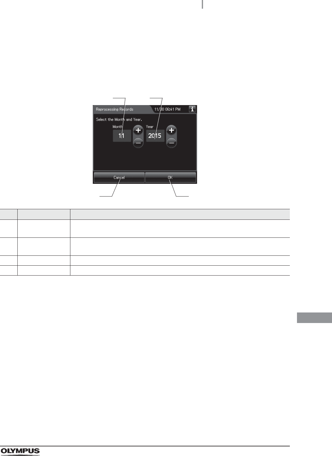
1Press the “Select Month” button.
2Enter the year and month.
No. Item/Button Description
1 Month Set the month of the start date of the period to be viewed. Pressing the + button
increments the setting and pressing the – button decrements it.
2 Year Set the day of the start date of the period to be viewed. Pressing the + button increments
the setting and pressing the – button decrements it.
3 Cancel Returns to the previous screen page.
4 OK Advances to the end date setting.
3Press the “OK” button. The list of the records in the selected month appears.
3 4
1 2
470
11.2 Log display and output
OER-Elite OPERATION MANUAL
Ch.11
Information recorded in each record
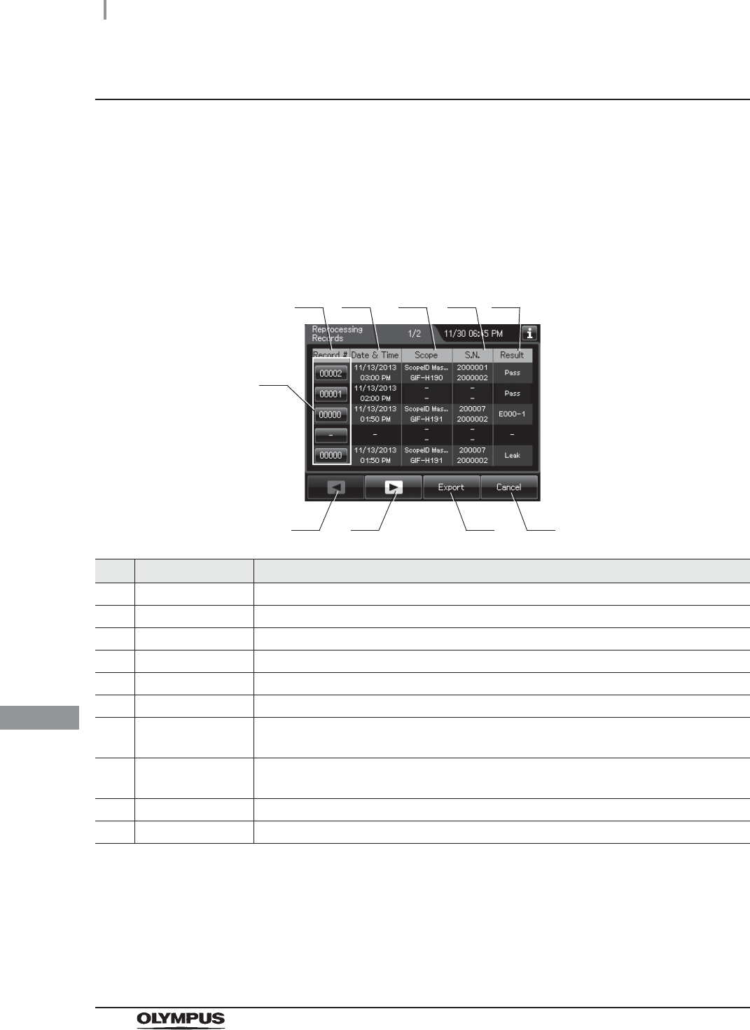
Reprocessing Records
(a) Records list
The list of entire data records of the selected range will be displayed. Five items of data items in
the records are displayed per a page.
Press the “Record number” button to check more information.
No. Item/Button Description
1 Record # Number given to each record in the order of reprocessing process.
2 Date & time Date and time of completion of reprocessing process.
3 Scope Model number of reprocessed endoscope(s).
4 S.N. Serial number(s) of reprocessed endoscope(s).
5 Result Result of reprocessing process.
6 Record # button Press to check the details of each record.
7 Previous page
button
Press to return to the previous page. When there is no further page to turn back to, the
button turns gray and becomes unavailable.
8 Next page button Press to go to the next page. When there is no further page to go forward to, the button
turns gray and becomes unavailable.
9 Export button Press to send the entire data records of the selected range to a portable memory.
10 Cancel button Returns to the viewing range selection screen.
1
7 9
2 3 4 5
6
810

11.2 Log display and output
471
OER-Elite OPERATION MANUAL
Ch.11
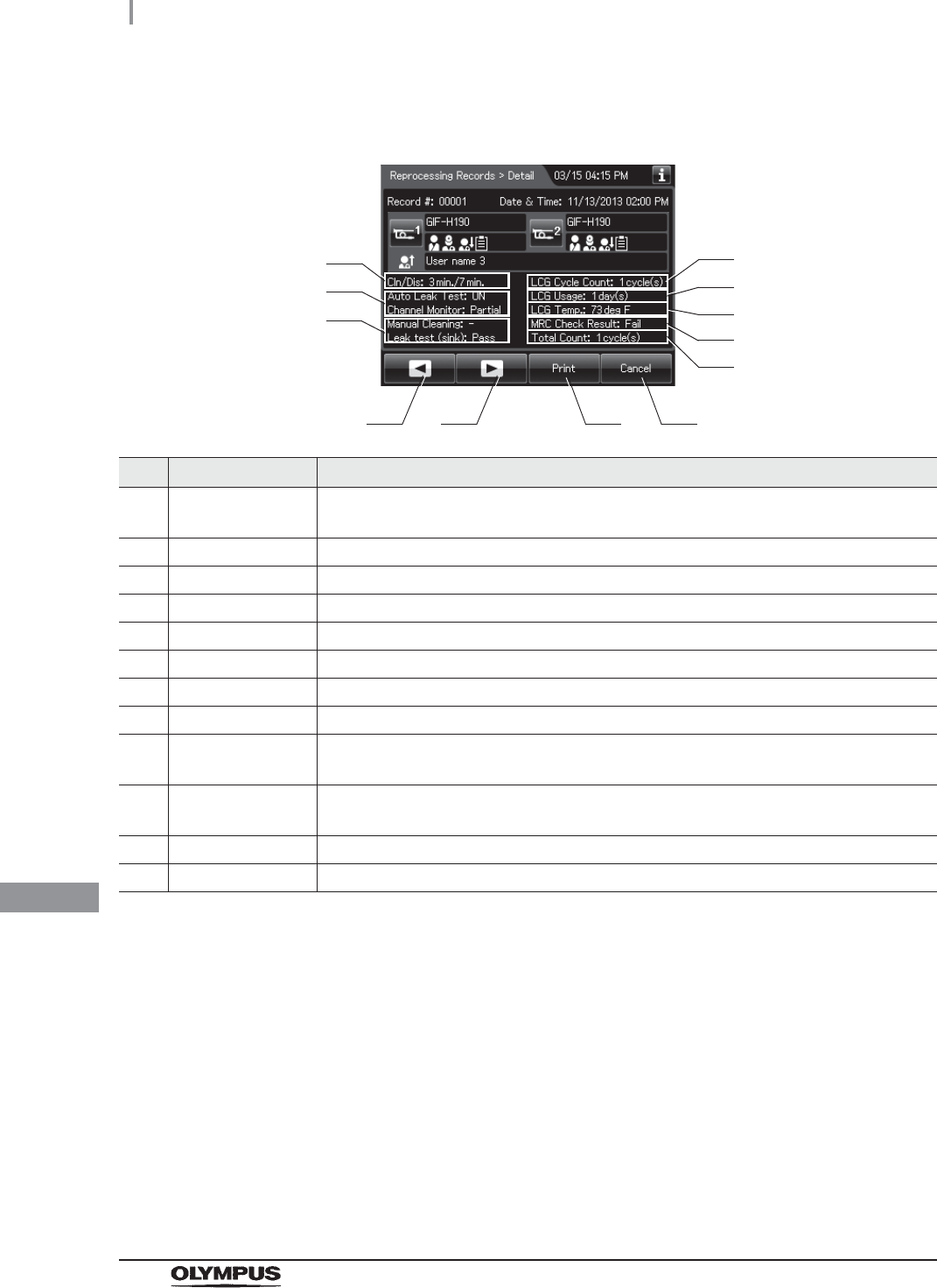
(b) Record details – Normal (When reprocessing completed successfully)
No. Item/Button Description
1 Record # Number given to each record in the order of occurrence.
2 Date & time Date and time of completion of reprocessing.
3 Scope 1 button Press to check the ID information related to the first endoscope. For detail, refer to
“Confirmation of the input ID” on page 64.
4 Scope 1 model
number
Model number of reprocessed first endoscope.
5 ID status of scope 1 Displays the input status of patient ID, physician ID, user ID (load), and procedure ID
associated with the first scope.
6 Scope 2 button Press to check the ID information related to the second endoscope. For detail, refer to
“Confirmation of the input ID” on page 64.
7 Scope 2 model
number
Model number of reprocessed second endoscope.
8 ID status of scope 2 Displays the input status of patient ID, physician ID, user ID (load), and procedure ID
associated with the second scope.
9 User name (End of
reprocessing)
Name of user who removed the endoscope(s) and the accessories.
1
3
2
4
5
6
7
8
9
472
11.2 Log display and output
OER-Elite OPERATION MANUAL
Ch.11
No. Item/Button Description
10 Cleaning/
disinfection time
Cleaning time/disinfection time (minutes).
11 Program Info. Setting of reprocessing program.
12 Input result Input results of manual cleaning and leak test.
13 LCG Cycle Count Usage count of the disinfectant solution.
14 LCG Usage Elapsed days since loading of the disinfectant solution.
15 LCG Temp. Temperature of disinfectant solution at the end of heating.
16 MRC Check Result Input result of MRC check.
17 Total Count Total count of the reprocessor.
18 Previous page
button
Press to show the former record. When there is no further page to turn back to, the
button turns gray and becomes unavailable.
19 Next page button Press to show the later record. When there is no further page to go forward to, the
button turns gray and becomes unavailable.
20 Print button Press to print the record by using an optional printer.
21 Cancel button Returns to record list.
18 20
10
19 21
13
15
11
12
14
16
17

11.2 Log display and output
473
OER-Elite OPERATION MANUAL
Ch.11
(c) Record details – Error (Except for E114)
No. Item/Button Description
1 Record # Number given to each record in the order of occurrence.
2 Date & time Date and time of occurrence of error.
3 Scope 1 button Press to check the ID information related to the first endoscope. For detail, refer to
“Confirmation of the input ID” on page 64.
4 Scope 1 model
number
Model number of reprocessed first endoscope.
5 ID status of scope 1 Displays the input status of patient ID, physician ID, user ID (load), and procedure ID
associated with the first scope.
6 Scope 2 button Press to check the ID information related to the second endoscope. For detail, refer to
“Confirmation of the input ID” on page 64.
7 Scope 2 model
number
Model number of reprocessed second endoscope.
8 ID status of scope 2 Displays the input status of patient ID, physician ID, user ID (load), and procedure ID
associated with the second scope.
9 Error code Error code, error details.
10 Error Info. Information required for contacting Olympus.
11 Previous page
button
Press to show the former record. When there is no further page to turn back to, the
button turns gray and becomes unavailable.
12 Next page button Press to show the later record. When there is no further page to go forward to, the
button turns gray and becomes unavailable.
13 Print button Press to print the record on the optional printer.
14 Cancel button Returns to record list.
11 1312 14
1 2
3
4
5
6
7
8
9
10
474
11.2 Log display and output
OER-Elite OPERATION MANUAL
Ch.11
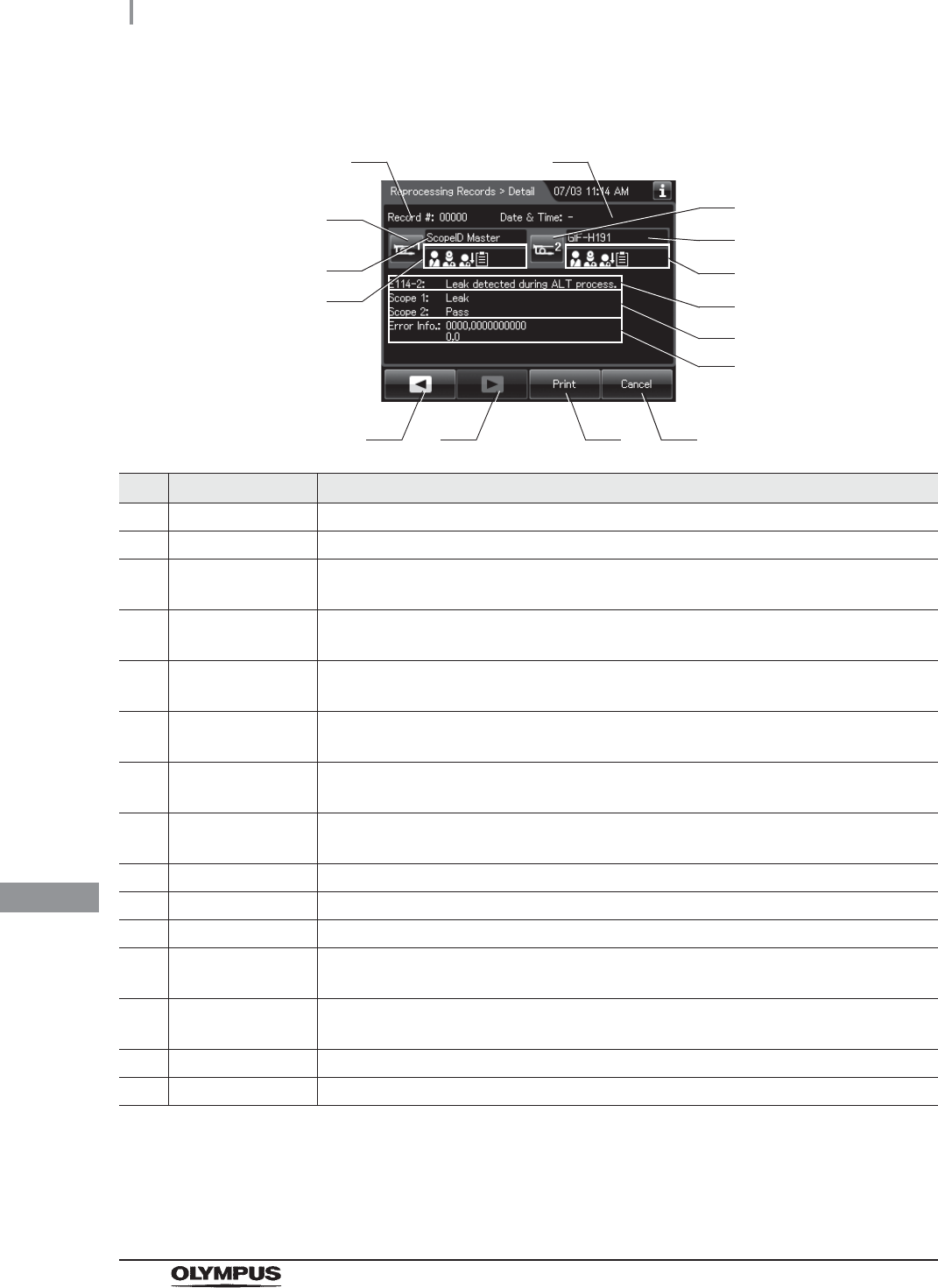
(d) Record details – Error (When leak was detected, E114)
No. Item/Button Description
1 Record # Number given to each record in the order of occurrence.
2 Date & time Date and time of occurrence of error.
3 Scope 1 button Press to check the ID information related to the first endoscope. For detail, refer to
“Confirmation of the input ID” on page 64.
4 Scope 1 model
number
Model number of reprocessed first endoscope.
5 ID status of scope 1 Displays the input status of patient ID, physician ID, user ID (load), and procedure ID
associated with the first scope.
6 Scope 2 button Press to check the ID information related to the second endoscope. For detail, refer to
“Confirmation of the input ID” on page 64.
7 Scope 2 model
number
Model number of reprocessed second endoscope.
8 ID status of scope 2 Displays the input status of patient ID, physician ID, user ID (load), and procedure ID
associated with the second scope.
9 Error code Error code, error details.
10 Result Results of auto leak test.
11 Error Info. Information required for contacting Olympus.
12 Previous page
button
Press to show the former record. When there is no further page to turn back to, the
button turns gray and becomes unavailable.
13 Next page button Press to show the later record. When there is no further page to go forward to, the
button turns gray and becomes unavailable.
14 Print button Press to print the record on the optional printer.
15 Cancel button Returns to record list.
12 1413 15
1 2
3
4
5
6
7
8
9
10
11

11.2 Log display and output
475
OER-Elite OPERATION MANUAL
Ch.11
Error Records
(a) Record list
No. Item/Button Description
1 Record # Number given to each record in the order of occurrence of error.
2 Date & Time Date and time of occurrence of error.
3 Error Code Error code.
4 Process Process in which error was generated.
5 Record # button Press to check the details of each record.
6 Previous page
button
Press to return to the previous page. When there is no further page to turn back to, the
button turns gray and becomes unavailable.
7 Next page button Press to go to the next page. When there is no further page to go forward to, the button
turns gray and becomes unavailable.
8 Export button Press to send the entire data items in the record of the selected range to a portable
memory.
9 Cancel button Returns to the viewing range selection screen.
1
6 8
2 3 4
5
7 9

476
11.2 Log display and output
OER-Elite OPERATION MANUAL
Ch.11
(b) Record details
No. Item/Button Description
1 Record # Number given to each record in the order of occurrence.
2 Date & time Date and time of occurrence of error.
3 Error Code Error code.
4 OER-Elite S.N. Reprocessor serial No.
5 Software Ver. Reprocessor software version.
6 Process Process in which error was generated.
7 Error Info. Information required for contacting Olympus.
8 Previous page
button
Press to show the former record. When there is no further page to turn back to, the
button turns gray and becomes unavailable.
9 Next page button Press to show the later record. When there is no further page to go forward to, the
button turns gray and becomes unavailable.
10 Cancel button Returns to record list.
8109
1 2
3
4
5
6
7
11.2 Log display and output
477
OER-Elite OPERATION MANUAL
Ch.11
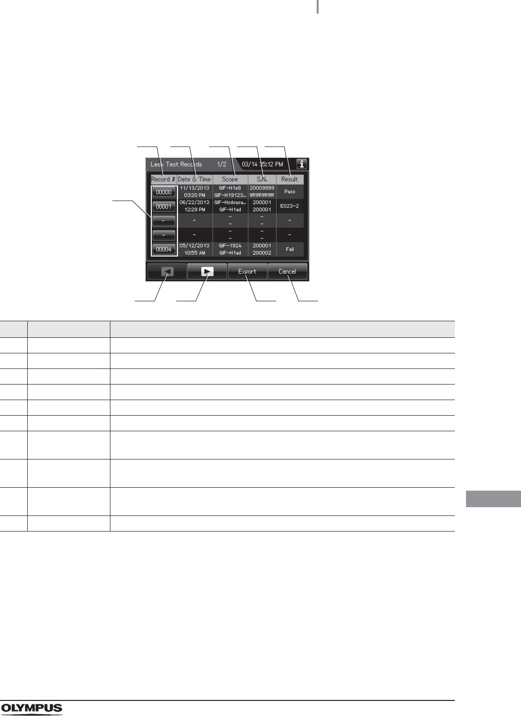
Leak Test Records
This section is defined the Auto Leak test records and Manual Leak test records.
(a) Record list
No. Item/Button Description
1 Record # Number given to each record in order of leak test.
2 Date & Time Date and time of completion of leak test.
3 Scope Model number of endoscope(s).
4 S.N. Serial number of endoscopes.
5 Result Result of each record.
6 Record # button Press to check the details of each record.
7 Previous page
button
Press to return to the previous page. When there is no further page to turn back to, the
button turns gray and becomes unavailable.
8 Next page button Press to go to the next page. When there is no further page to go forward to, the button
turns gray and becomes unavailable.
9 Export button Press to send the entire data items in the record of the selected range to the portable
memory.
10 Cancel button Returns to the viewing range selection screen.
1
7 9
2 3
6
810
54
478
11.2 Log display and output
OER-Elite OPERATION MANUAL
Ch.11
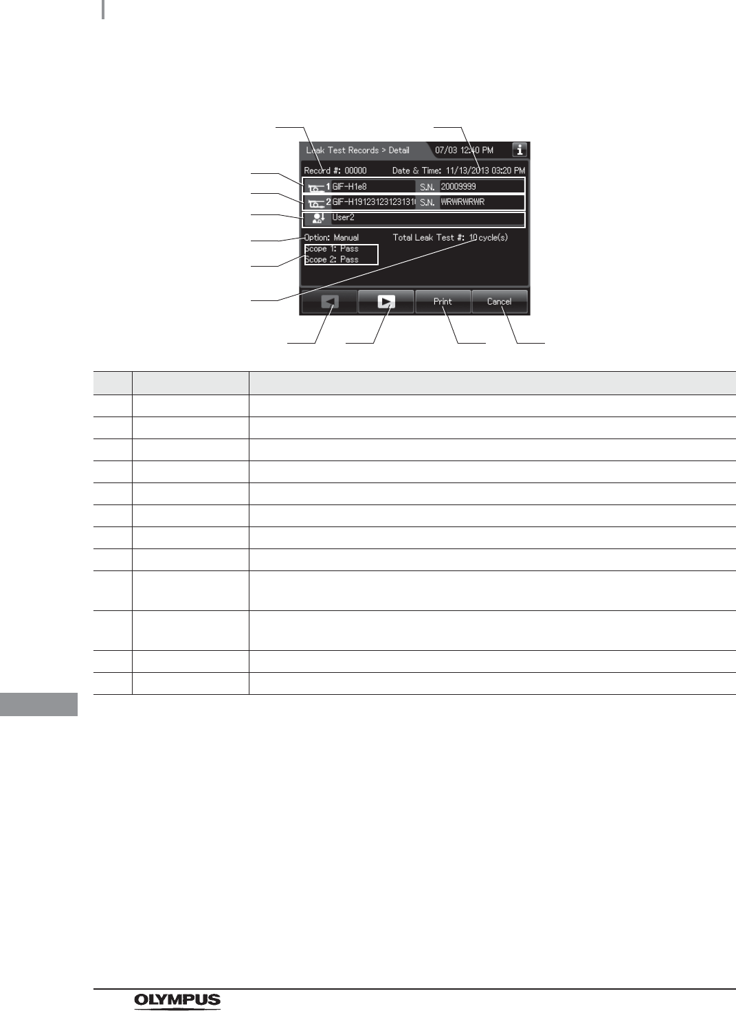
(b) Record details – Normal
No. Item/Button Description
1 Record # Number given to each record in the order of occurrence.
2 Date & time Date and time of occurrence of error.
3 Scope 1 Info. Model number and serial number of first endoscope.
4 Scope 2 Info. Model number and serial number of second endoscope.
5 User name Name of user who performed leak test.
6 Test type Type of leak test.
7 Result Results of leak test.
8 Total Leak Test Total counts of leak test of the reprocessor.
9 Previous page
button
Press to return to the previous page. When there is no further page to turn back to, the
button turns gray and becomes unavailable.
10 Next page button Press to go to the next page. When there is no further page to go forward to, the button
turns gray and becomes unavailable.
11 Print button Press to print the record on the optional printer.
12 Cancel button Returns to record list.
3
91210
4
5
6
8
11
7
1 2

11.2 Log display and output
479
OER-Elite OPERATION MANUAL
Ch.11
(c) Record details – Error
No. Item/Button Description
1 Record # Number given to each record in the order of occurrence.
2 Date & time Date and time of occurrence of error.
3 Scope 1 Info. Model number and serial number of the first endoscope.
4 Scope 2 Info. Model number and serial number of the second endoscope.
5 User name Name of user who performed leak test.
6 Test type Type of leak test.
7 Error code Error code, error details.
8 Error Info. Information required for contacting Olympus.
9 Previous page
button
Press to show the former record. When there is no further page to turn back to, the
button turns gray and becomes unavailable.
10 Next page button Press to show the later record. When there is no further page to go forward to, the
button turns gray and becomes unavailable.
11 Print button Press to print the record on the optional printer.
12 Cancel button Returns to record list.
91210
3
4
6
7
11
5
1 2
8
480
11.2 Log display and output
OER-Elite OPERATION MANUAL
Ch.11
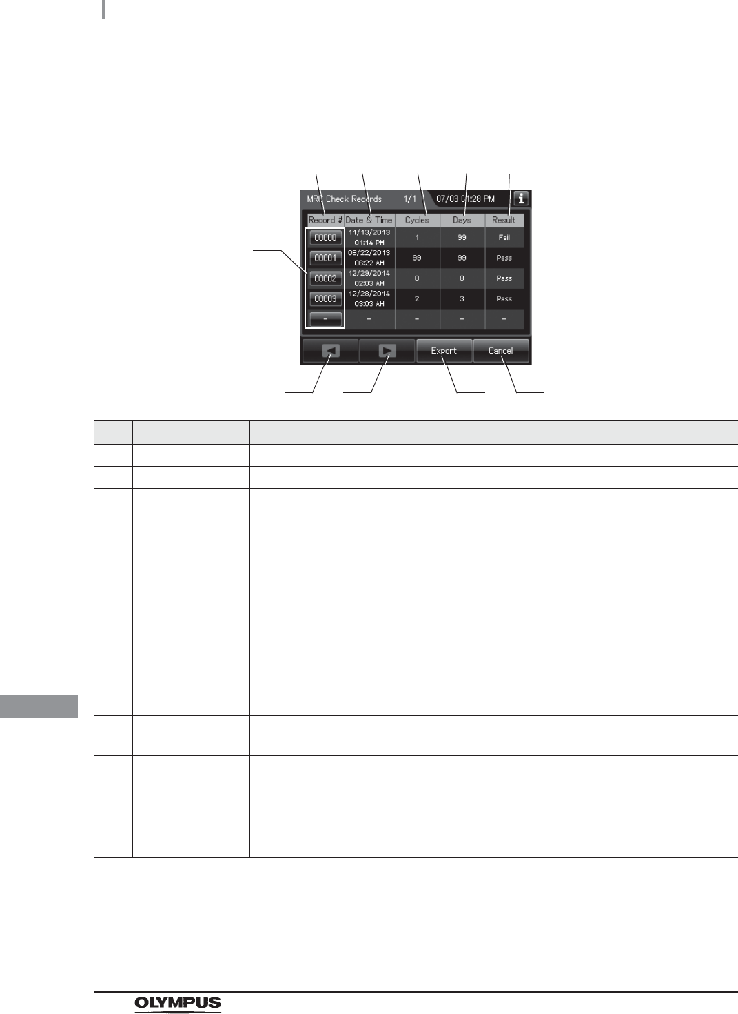
MRC Check Records
(a) Record list
No. Item/Button Description
1 Record # Number given to each record in order of MRC Check.
2 Date & Time Date and time of completion of MRC check.
3 Cycles Usage count of the disinfectant solution.
Disinfectant solution is used at following functions:
Reprocessing process
Water line disinfection
Self-disinfection & water sampling
Detergent line disinfection
Alcohol line disinfection
Leaking scope decontamination.
4 Days Elapsed days since loading of the disinfectant solution.
5 Result Result of MRC check.
6 Record # button Press to check the details of each record.
7 Previous page
button
Press to show the former record. When there is no further page to turn back to, the
button turns gray and becomes unavailable.
8 Next page button Press to show the later record. When there is no further page to go forward to, the
button turns gray and becomes unavailable.
9 Export button Press to send the entire data items in the record of the selected range to the portable
memory.
10 Cancel button Returns to the viewing range selection screen.
1
7 9
2 3 4 5
6
810
11.2 Log display and output
481
OER-Elite OPERATION MANUAL
Ch.11
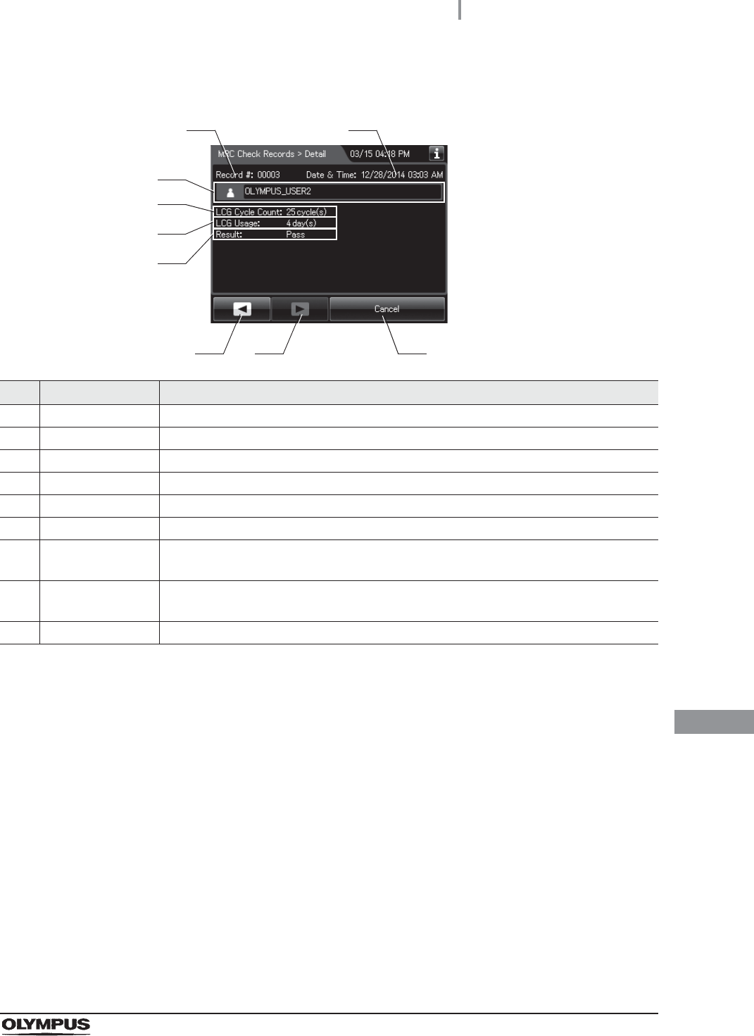
(b) Record details
No. Item/Button Description
1 Record # Number given to each record in the order of occurrence.
2 Date & time Date and time of completion of MRC Check.
3 User name Name of user who performed MRC check.
4 LCG Cycle Count Usage count of the disinfectant solution.
5 LCG Usage Elapsed days since loading of the disinfectant solution.
6 Result Input result of MRC check.
7 Previous page
button
Press to show the former record. When there is no further page to turn back to, the
button turns gray and becomes unavailable.
8 Next page button Press to show the later record. When there is no further page to go forward to, the
button turns gray and becomes unavailable.
9 Cancel button Returns to record list.
3
7 8
4
5
9
6
1 2
482
11.2 Log display and output
OER-Elite OPERATION MANUAL
Ch.11
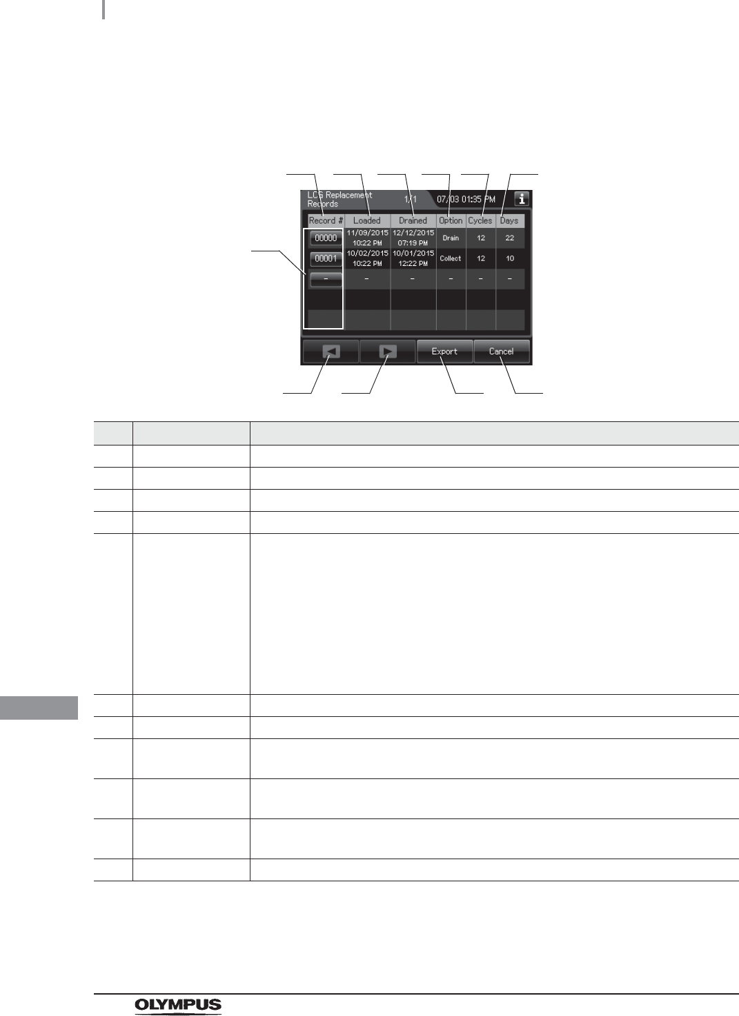
LCG Replacement Records
(a) Record list
No. Item/Button Description
1 Record # Number given to each record in the order of replacing LCG.
2 Loaded Date and time of completion of draining disinfectant solution.
3 Drained Date and time of completion of draining disinfectant solution.
4 Option Method of draining of disinfectant solution.
5 Cycles Usage count of the disinfectant solution.
Disinfectant solution is used at following functions:
Reprocessing process
Water line disinfection
Self-disinfection & water sampling
Detergent line disinfection
Alcohol line disinfection
Leaking scope decontamination.
6 Days Elapsed days since loading of the disinfectant solution.
7 Record # button Press to check the details of each record.
8 Previous page
button
Press to show the former record. When there is no further page to turn back to, the
button turns gray and becomes unavailable.
9 Next page button Press to show the later record. When there is no further page to go forward to, the
button turns gray and becomes unavailable.
10 Export button Press to send the entire data items in the record of the selected range to the portable
memory.
11 Cancel button Returns to the viewing range selection screen.
1
810
2 3 4 5
7
911
6
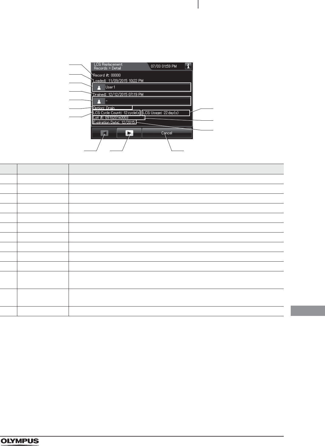
11.2 Log display and output
483
OER-Elite OPERATION MANUAL
Ch.11
(b) Record details
No. Item/Button Description
1 Record # Number given to each record in the order of occurrence.
2 Loaded date & time Date and time of completion of loading of disinfectant solution
3 Loaded user name Name of user who loaded disinfectant solution.
4 Drained date & time Date and time of completion of draining disinfectant solution
5 Drained user name Name of user who drained disinfectant solution.
6 Option Method of drain disinfectant solution.
7 LCG Cycle Count Usage count of the disinfectant solution.
8 LCG Usage Elapsed days from loaded date to drained date.
9 Lot # Lot number of the disinfectant solution.
10 Expiration Date Expiration date of the disinfectant solution.
11 Previous page
button
Press to show the former record. When there is no further page to turn back to, the
button turns gray and becomes unavailable.
12 Next page button Press to show the later record. When there is no further page to go forward to, the
button turns gray and becomes unavailable.
13 Cancel button Returns to record list.
11 12 13
1
2
3
4
5
6
7
8
9
10
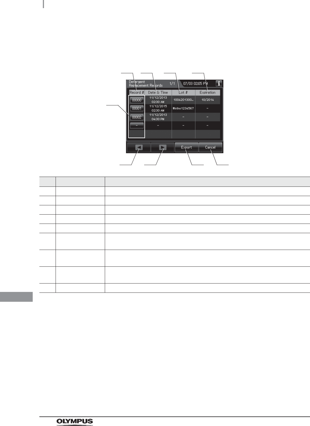
484
11.2 Log display and output
OER-Elite OPERATION MANUAL
Ch.11
Detergent Replacement Records
(a) Record list
No. Item/Button Description
1 Record # Number given to each record in the order of replacing detergent.
2 Date & Time Date and time of completion of replacement of detergent.
3 Lot # Lot number of detergent.
4 Expiration Expiration date of detergent.
5 Record # button Press to check the details of each record.
6 Previous page
button
Press to show the former record. When there is no further page to turn back to, the
button turns gray and becomes unavailable.
7 Next page button Press to show the later record. When there is no further page to go forward to, the
button turns gray and becomes unavailable.
8 Export button Press to send the entire data items in the record of the selected range to the portable
memory.
9 Cancel button Returns to the viewing range selection screen.
1
6 8
2 3 4
5
7 9
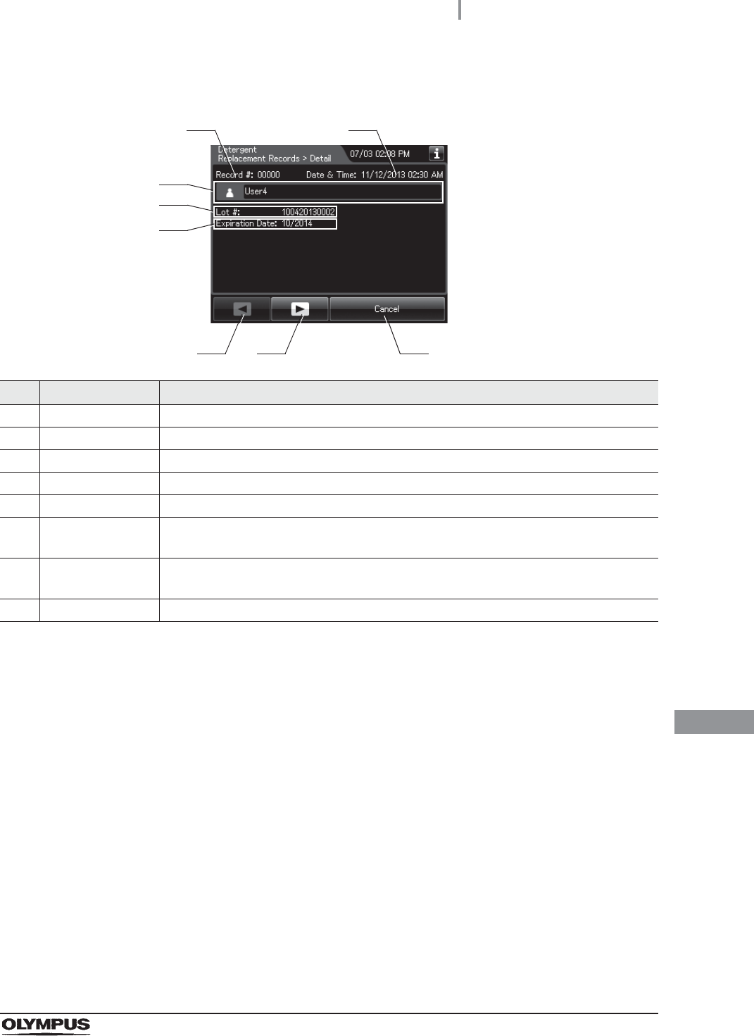
11.2 Log display and output
485
OER-Elite OPERATION MANUAL
Ch.11
(b) Record details
No. Item/Button Description
1 Record # Number given to each record in the order of occurrence.
2 Date & Time Date and time of completion of replacement of detergent.
3 User name Name of user who replaced detergent.
4 Lot Lot number of detergent.
5 Expiration date Expiration date of detergent.
6 Previous page
button
Press to show the former record. When there is no further page to turn back to, the
button turns gray and becomes unavailable.
7 Next page button Press to show the later record. When there is no further page to go forward to, the
button turns gray and becomes unavailable.
8 Cancel button Returns to record list.
6 7
3
8
1 2
4
5
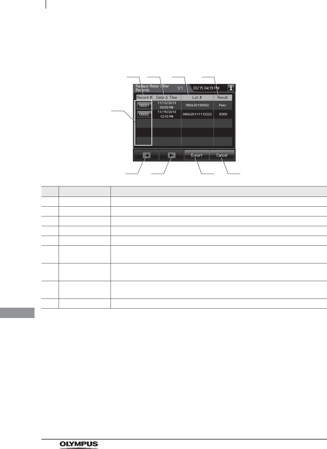
486
11.2 Log display and output
OER-Elite OPERATION MANUAL
Ch.11
Water Filter Replacement Records
(a) Record list
No. Item/Button Description
1 Record # Number given to each record in the order of replacing water filter.
2 Date & Time Date and time of completion of replacement of water filter.
3 Lot # Lot number of water filter.
4 Result Result of replacement of water filter.
5 Record # button Press to check the details of each record.
6 Previous page
button
Press to show the former record. When there is no further page to turn back to, the
button turns gray and becomes unavailable.
7 Next page button Press to show the later record. When there is no further page to go forward to, the
button turns gray and becomes unavailable.
8 Export button Press to send the entire data items in the record of the selected range to the portable
memory.
9 Cancel button Returns to the viewing range selection screen.
1
6 8
2 3 4
5
7 9

11.2 Log display and output
487
OER-Elite OPERATION MANUAL
Ch.11
(b) Record details – Normal
No. Item/Button Description
1 Record# Number given to each record in order of occurrence.
2 Date & Time Date and time of completion of replacement of water filter.
3 User name Name of user who replaced water filter.
4 Lot # Lot number of water filter.
5 Previous page
button
Press to show the former record. When there is no further page to turn back to, the
button turns gray and becomes unavailable.
6 Next page button Press to show the later record. When there is no further page to go forward to, the
button turns gray and becomes unavailable.
7 Cancel button Returns to record list.
5 6
3
4
7
1 2

488
11.2 Log display and output
OER-Elite OPERATION MANUAL
Ch.11
(c) Record details – Error
No. Item/Button Description
1 Record # Number given to each record in the order of occurrence.
2 Date & time Date and time of occurrence of error.
3 User name Name of user who replaced the water filter.
4 Error code Error code, error details.
5 Error Info. Information required for contacting Olympus.
6 Previous page
button
Press to show the former record. When there is no further page to turn back to, the
button turns gray and becomes unavailable.
7 Next page button Press to show the later record. When there is no further page to go forward to, the
button turns gray and becomes unavailable.
8 Cancel button Returns to record list.
6 7
3
8
4
1 2
5

11.2 Log display and output
489
OER-Elite OPERATION MANUAL
Ch.11
Air Filter Replacement Records
(a) Record list
No. Item/Button Description
1 Record # Number given to each record in the order of replacing air filter.
2 Date & Time Date and time of completion of replacement of air filter.
3 Lot # Lot number of air filter.
4 Record # button Press to check the details of each record.
5 Previous page
button
Press to show the former record. When there is no further page to turn back to, the
button turns gray and becomes unavailable.
6 Next page button Press to show the later record. When there is no further page to go forward to, the
button turns gray and becomes unavailable.
7 Export button Press to send the entire data items in the record of the selected range to the portable
memory.
8 Cancel button Returns to the viewing range selection screen.
1
5 7
2 3
4
6 8
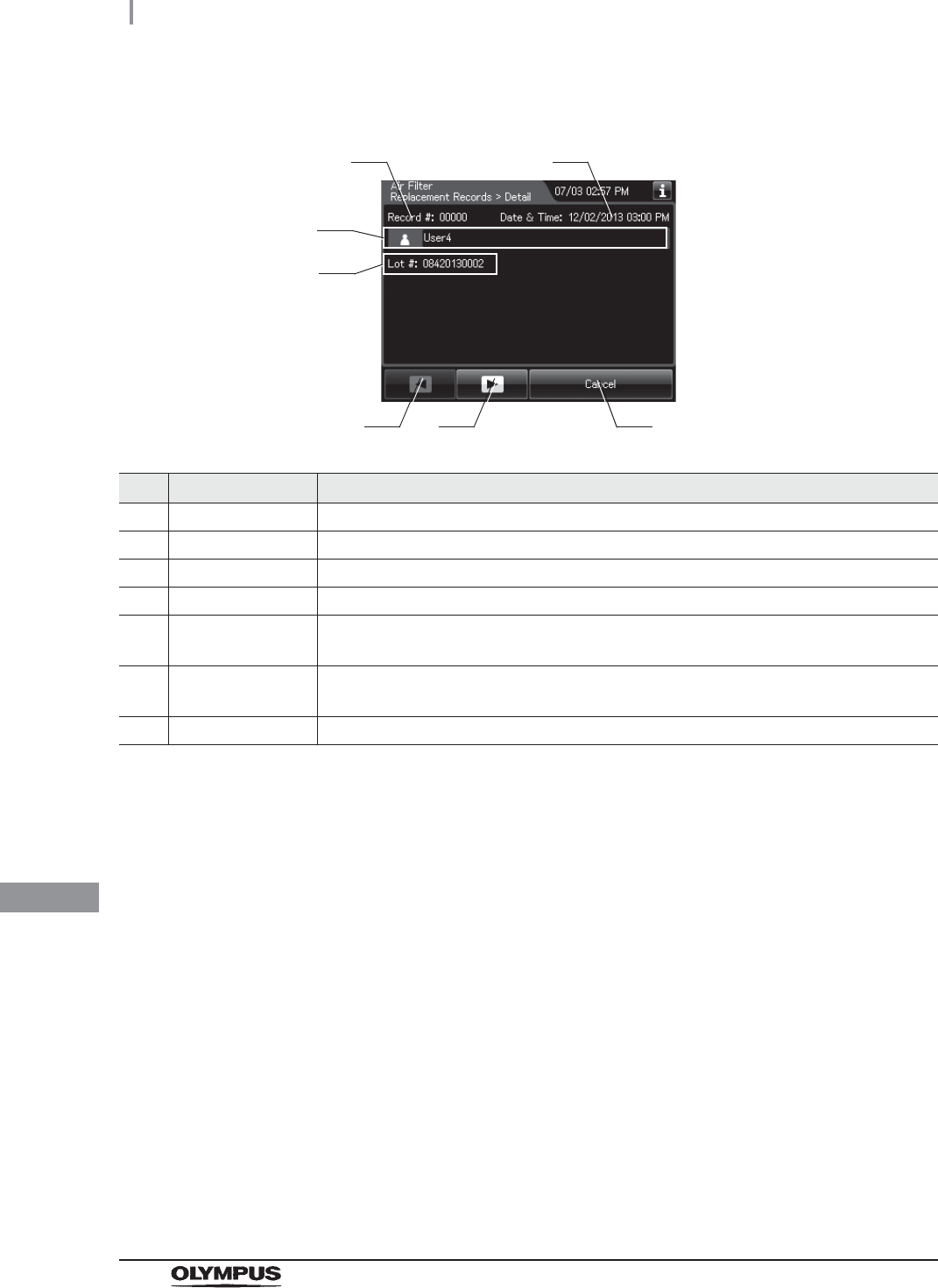
490
11.2 Log display and output
OER-Elite OPERATION MANUAL
Ch.11
(b) Record details
No. Item/Button Description
1 Record # Number given to each record in the order of occurrence.
2 Date & Time Date and time of completion of replacement of air filter.
3 User name Name of user who replaced air filter.
4 Lot # Lot number of air filter.
5 Previous page
button
Press to show the former record. When there is no further page to turn back to, the
button turns gray and becomes unavailable.
6 Next page button Press to show the later record. When there is no further page to go forward to, the
button turns gray and becomes unavailable.
7 Cancel button Returns to record list.
5 6 7
1 2
4
3

11.2 Log display and output
491
OER-Elite OPERATION MANUAL
Ch.11
Gas Filter (Lid) Replacement Records
(a) Record list
No. Item/Button Description
1 Record # Number given to each record in the order of replacing gas filter on the lid.
2 Date & Time Date and time of completion of replacement of gas filter on the lid.
3 Lot # Lot number of gas filter on the lid.
4 Record # button Press to check the details of each record.
5 Previous page
button
Press to show the former record. When there is no further page to turn back to, the
button turns gray and becomes unavailable.
6 Next page button Press to show the later record. When there is no further page to go forward to, the
button turns gray and becomes unavailable.
7 Export button Press to send the entire data items in the record of the selected range to the portable
memory.
8 Cancel button Returns to the viewing range selection screen.
1
5 7
2 3
4
6 8

492
11.2 Log display and output
OER-Elite OPERATION MANUAL
Ch.11
(b) Record details
No. Item/Button Description
1 Record # Number given to each record in the order of occurrence.
2 Date & Time Date and time of completion of replacement of gas filter on the lid.
3 User name Name of user who replaced gas filter on the lid.
4 Lot # Lot number of gas filter on the lid.
5 Previous page
button
Press to show the former record. When there is no further page to turn back to, the
button turns gray and becomes unavailable.
6 Next page button Press to show the later record. When there is no further page to go forward to, the
button turns gray and becomes unavailable.
7 Cancel button Returns to record list.
5 6 7
1 2
4
3

11.2 Log display and output
493
OER-Elite OPERATION MANUAL
Ch.11
Gas Filter (Tank) Replacement Records
(a) Record list
No. Item/Button Description
1 Record # Number given to each record in the order of replacing gas filter on the tank.
2 Date & Time Date and time of completion of replacement of gas filter on the tank.
3 Lot # Lot number of gas filter on the tank.
4 Record # button Press to check the details of each record.
5 Previous page
button
Press to show the former record. When there is no further page to turn back to, the
button turns gray and becomes unavailable.
6 Next page button Press to show the later record. When there is no further page to go forward to, the
button turns gray and becomes unavailable.
7 Export button Press to send the entire data items in the record of the selected range to the portable
memory.
8 Cancel button Returns to the viewing range selection screen.
1
5 7
2 3
4
6 8

494
11.2 Log display and output
OER-Elite OPERATION MANUAL
Ch.11
(b) Record details
No. Item/Button Description
1 Record # Number given to each record in the order of occurrence.
2 Date & Time Date and time of completion of replacement of gas filter on the tank.
3 User name Name of user who replaced gas filter on the tank.
4 Lot # Lot number of gas filter on the tank.
5 Previous page
button
Press to show the former record. When there is no further page to turn back to, the
button turns gray and becomes unavailable.
6 Next page button Press to show the later record. When there is no further page to go forward to, the
button turns gray and becomes unavailable.
7 Cancel button Returns to record list.
5 6
4
7
3
1 2

11.2 Log display and output
495
OER-Elite OPERATION MANUAL
Ch.11
Water Line Disinfection Records
(a) Record list
No. Item/Button Description
1 Record # Number given to each record in order of water line disinfection.
2 Date & Time Date and time of completion of water line disinfection.
3 Cycles Number of times the disinfectant solution has been used.
Disinfectant solution is used at following functions:
Reprocessing process
Water line disinfection
Self-disinfection & water sampling
Detergent line disinfection
Alcohol line disinfection
Leaking scope decontamination.
4 Days Number of days that have elapsed since preparation of the disinfectant solution.
5 Result Result of water line disinfection.
6 Record # button Press to check the details of each record.
7 Previous page
button
Press to show the former record. When there is no further page to turn back to, the
button turns gray and becomes unavailable.
8 Next page button Press to show the later record. When there is no further page to go forward to, the
button turns gray and becomes unavailable.
9 Export button Press to send the entire data items in the record of the selected range to the portable
memory.
10 Cancel button Returns to the viewing range selection screen.
1
7 9
2 3 4 5
6
810
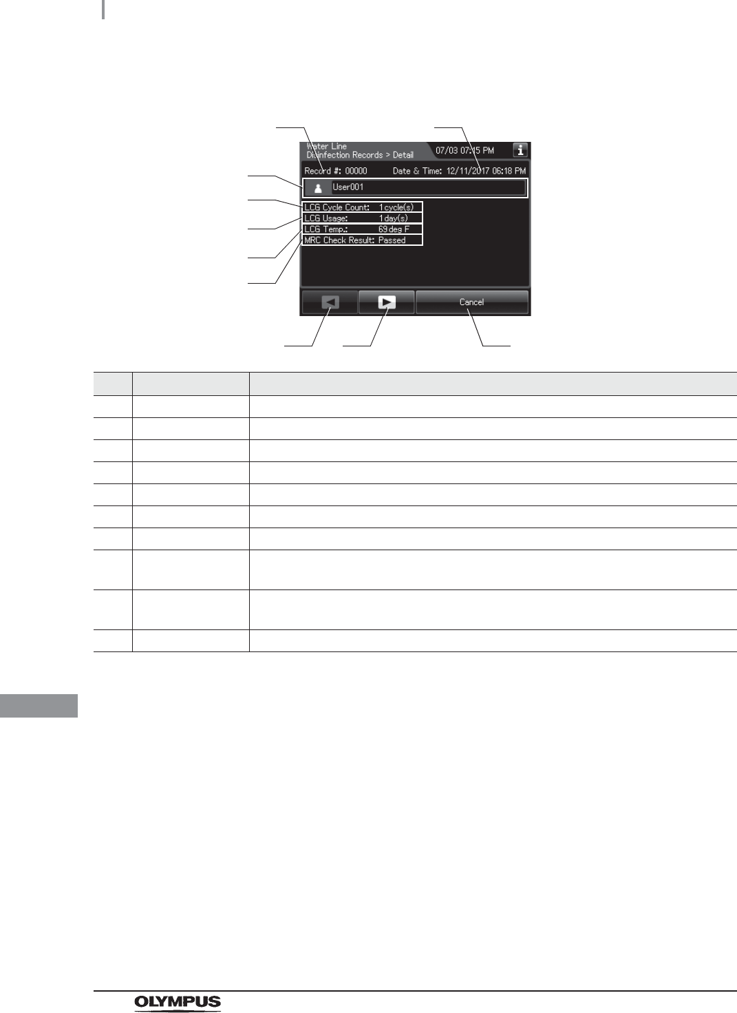
496
11.2 Log display and output
OER-Elite OPERATION MANUAL
Ch.11
(b) Record details – Normal
No. Item/Button Description
1 Record # Number given to each record in the order of occurrence.
2 Date & time Date and time of completion of water line disinfection.
3 User name Name of user who performed water line disinfection.
4 LCG Cycle Count Usage count of the disinfectant solution.
5 LCG Usage Number of days that have elapsed since preparation of the disinfectant solution.
6 LCG Temp. Temperature of disinfectant solution at the end of heating.
7 MRC Check Result Input result of MRC check.
8 Previous page
button
Press to show the former record. When there is no further page to turn back to, the
button turns gray and becomes unavailable.
9 Next page button Press to show the later record. When there is no further page to go forward to, the
button turns gray and becomes unavailable.
10 Cancel button Returns to record list.
3
8 9
4
5
10
6
1 2
7

11.2 Log display and output
497
OER-Elite OPERATION MANUAL
Ch.11
(c) Record details – Error
No. Item/Button Description
1 Record # Number given to each record in the order of occurrence.
2 Date & Time Date and time of occurrence of error.
3 User name Name of user who performed water line disinfection.
4 Error code Error code, error details.
5 Error info. Information required for contacting Olympus.
6 Previous page
button
Press to show the former record. When there is no further page to turn back to, the
button turns gray and becomes unavailable.
7 Next page button Press to show the later record. When there is no further page to go forward to, the
button turns gray and becomes unavailable.
8 Cancel button Returns to record list.
3
6 7
4
8
5
1 2
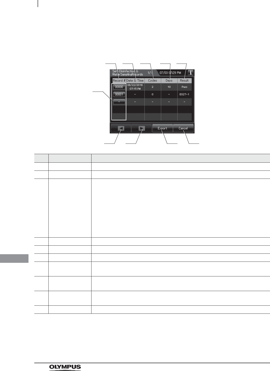
498
11.2 Log display and output
OER-Elite OPERATION MANUAL
Ch.11
Self-Disinfection & Water Sampling Records
(a) Record list
No. Item/Button Description
1 Record # Number given to each record in order of self disinfection and water sampling.
2 Date & Time Date and time of completion of self disinfection and water sampling.
3 Cycles Number of times the disinfectant solution has been used.
Disinfectant solution is used at following functions:
Reprocessing process
Water line disinfection
Self-disinfection & water sampling
Detergent line disinfection
Alcohol line disinfection
Leaking scope decontamination.
4 Days Number of days that have elapsed since preparation of the disinfectant solution.
5 Result Result of self disinfection and water sampling.
6 Record # button Press to check the details of each record.
7 Previous page
button
Press to show the former record. When there is no further page to turn back to, the
button turns gray and becomes unavailable.
8 Next page button Press to show the later record. When there is no further page to go forward to, the
button turns gray and becomes unavailable.
9 Export button Press to send the entire data items in the record of the selected range to the portable
memory.
10 Cancel button Returns to the viewing range selection screen.
1
7 9
2 3 4 5
6
810

11.2 Log display and output
499
OER-Elite OPERATION MANUAL
Ch.11
(b) Record details – Normal
No. Item/Button Description
1 Record # Number given to each record in the order of occurrence.
2 Date & time Date and time of completion of self-disinfection and water sampling.
3 User name Name of user who performed self-disinfection and water sampling.
4 LCG Cycle Count Usage count of the disinfectant solution.
5 LCG Usage Number of days that have elapsed since preparation of the disinfectant solution.
6 LCG Temp. Temperature of disinfectant solution at the end of heating.
7 MRC Check Result Input result of MRC check.
8 Previous page
button
Press to show the former record. When there is no further page to turn back to, the
button turns gray and becomes unavailable.
9 Next page button Press to show the later record. When there is no further page to go forward to, the
button turns gray and becomes unavailable.
10 Cancel button Returns to record list.
3
8 9
4
5
10
6
1 2
7

500
11.2 Log display and output
OER-Elite OPERATION MANUAL
Ch.11
(c) Record details – Error
No. Item/Button Description
1 Record # Number given to each record in the order of occurrence.
2 Date & Time Date and time of occurrence of error.
3 User name Name of user who performed self-disinfection & water sampling.
4 Error code Error code, error details.
5 Error info. Information required for contacting Olympus.
6 Previous page
button
Press to show the former record. When there is no further page to turn back to, the
button turns gray and becomes unavailable.
7 Next page button Press to show the later record. When there is no further page to go forward to, the
button turns gray and becomes unavailable.
8 Cancel button Returns to record list.
3
6 7
4
8
5
1 2
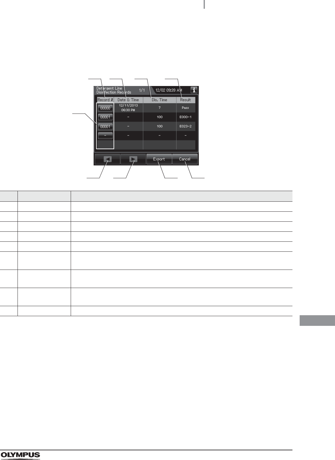
11.2 Log display and output
501
OER-Elite OPERATION MANUAL
Ch.11
Detergent Line Disinfection Records
(a) Record list
No. Item/Button Description
1 Record # Number given to each record in order of detergent line disinfection.
2 Date & Time Date and time of completion of detergent line disinfection.
3 Dis.Time Disinfection time.
4 Result Result of detergent line disinfection.
5 Record # button Press to check the details of each record.
6 Previous page
button
Press to show the former record. When there is no further page to turn back to, the
button turns gray and becomes unavailable.
7 Next page button Press to show the later record. When there is no further page to go forward to, the
button turns gray and becomes unavailable.
8 Export button Press to send the entire data items in the record of the selected range to the portable
memory.
9 Cancel button Returns to the viewing range selection screen.
1
6 8
2 3 4
5
7 9

502
11.2 Log display and output
OER-Elite OPERATION MANUAL
Ch.11
(b) Record details – Normal
No. Item/Button Description
1 Record # Number given to each record in the order of occurrence.
2 Date & Time Date and time of completion of detergent line disinfection.
3 User name Name of user who performed detergent line disinfection.
4 MRC Check Result Result of MRC check.
5 Disinfection Time Disinfection time.
6 Previous page
button
Press to show the former record. When there is no further page to turn back to, the
button turns gray and becomes unavailable.
7 Next page button Press to show the later record. When there is no further page to go forward to, the
button turns gray and becomes unavailable.
8 Cancel button Returns to record list.
3
6 7
4
5
8
1 2

11.2 Log display and output
503
OER-Elite OPERATION MANUAL
Ch.11
(c) Record details – Error
No. Item/Button Description
1 Record # Number given to each record in the order of occurrence.
2 Date & Time Date and time of occurrence of error.
3 User name Name of user who performed detergent line disinfection.
4 Error code Error code, error details.
5 Error info. Information required for contacting Olympus.
6 Previous page
button
Press to show the former record. When there is no further page to turn back to, the
button turns gray and becomes unavailable.
7 Next page button Press to show the later record. When there is no further page to go forward to, the
button turns gray and becomes unavailable.
8 Cancel button Returns to record list.
3
6 7
4
8
5
1 2
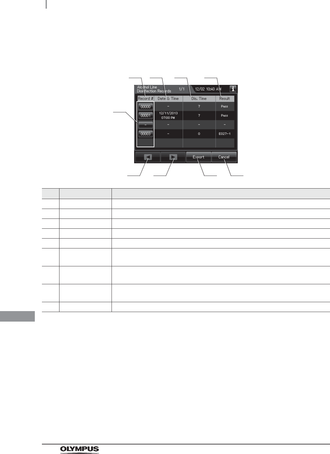
504
11.2 Log display and output
OER-Elite OPERATION MANUAL
Ch.11
Alcohol Line Disinfection Records
(a) Record list
No. Item/Button Description
1 Record # Number given to each record in order of alcohol line disinfection.
2 Date & Time Date and time of completion of alcohol line disinfection.
3 Dis. Time Disinfection time.
4 Result Result of alcohol line disinfection.
5 Record # button Press to check the details of each record.
6 Previous page
button
Press to show the former record. When there is no further page to turn back to, the
button turns gray and becomes unavailable.
7 Next page button Press to show the later record. When there is no further page to go forward to, the
button turns gray and becomes unavailable.
8 Export button Press to send the entire data items in the record of the selected range to the portable
memory.
9 Cancel button Returns to the viewing range selection screen.
1
6 8
2 3 4
5
7 9

11.2 Log display and output
505
OER-Elite OPERATION MANUAL
Ch.11
(b) Record details – Normal
No. Item/Button Description
1 Record # Number given to each record in the order of occurrence.
2 Date & Time Date and time of completion of alcohol line disinfection.
3 User name Name of user who performed alcohol line disinfection.
4 MRC Check Result Result of MRC check.
5 Disinfection Time Disinfection time.
6 Previous page
button
Press to show the former record. When there is no further page to turn back to, the
button turns gray and becomes unavailable.
7 Next page button Press to show the later record. When there is no further page to go forward to, the
button turns gray and becomes unavailable.
8 Cancel button Returns to record list.
3
6 7
4
5
8
1 2

506
11.2 Log display and output
OER-Elite OPERATION MANUAL
Ch.11
(c) Record details – Error
No. Item/Button Description
1 Record # Number given to each record in the order of occurrence.
2 Date & Time Date and time of occurrence of error.
3 User name Name of user who performed alcohol line disinfection.
4 Error code Error code, error details.
5 Error info. Information required for contacting Olympus.
6 Previous page
button
Press to show the former record. When there is no further page to turn back to, the
button turns gray and becomes unavailable.
7 Next page button Press to show the later record. When there is no further page to go forward to, the
button turns gray and becomes unavailable.
8 Cancel button Returns to record list.
3
6 7
4
8
5
1 2
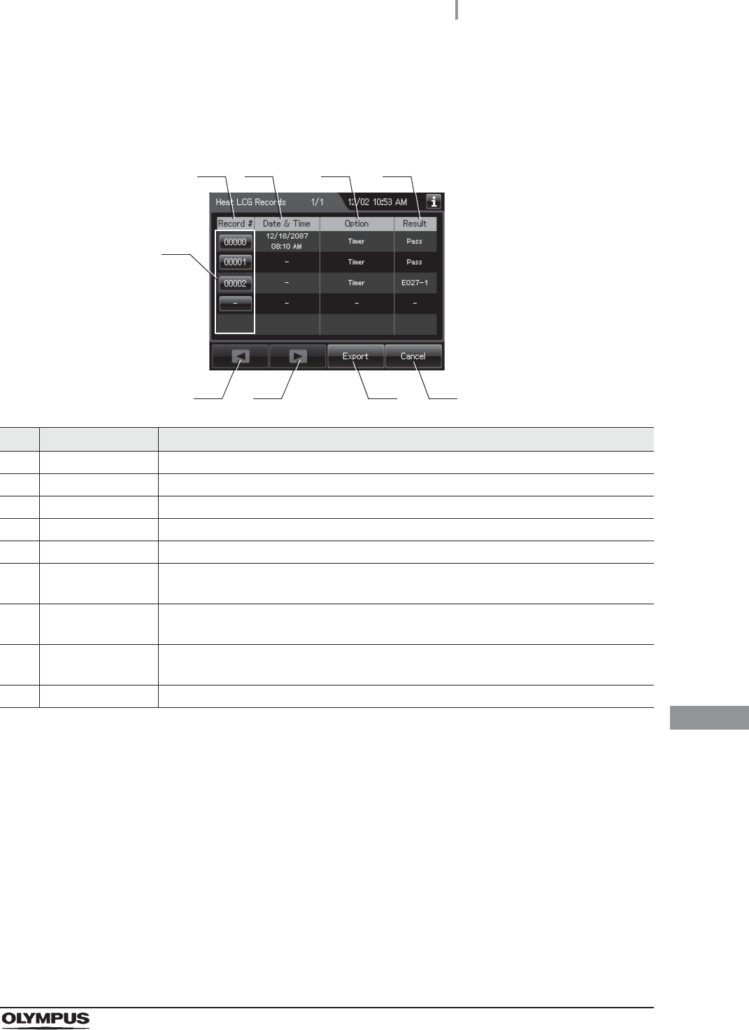
11.2 Log display and output
507
OER-Elite OPERATION MANUAL
Ch.11
Heat LCG Records
(a) Record list
No. Item/Button Description
1 Record # Number given to each record in the order of Heat LCG
2 Date & time Date and time of completion of Heat LCG.
3 Option Method of Heat LCG. “Timer” or “Manual” is represented.
4 Result Result of Heat LCG
5 Record # button Press to check the details of each record.
6 Previous page
button
Press to return to the previous page. When there is no further page to turn back to, the
button turns gray and becomes unavailable.
7 Next page button Press to go to the next page. When there is no further page to go forward to, the button
turns gray and becomes unavailable.
8 Export button Press to send the entire data items in the record of the selected range to the portable
memory.
9 Cancel button Returns to the viewing range selection screen.
1
6 8
2 3 4
5
7 9
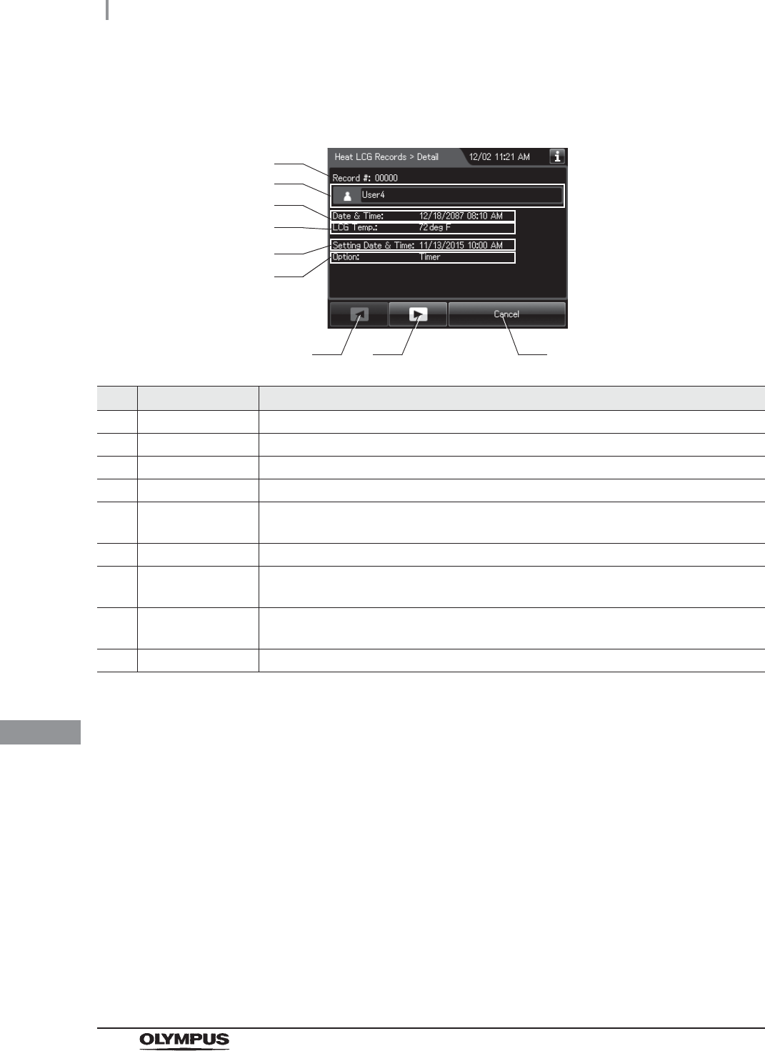
508
11.2 Log display and output
OER-Elite OPERATION MANUAL
Ch.11
(b) Record details – Normal
No. Item/Button Description
1 Record # Number given to each record in the order of occurrence.
2 User name Name of user who performed Heat LCG.
3 Date & time Date and time of completion of Heat LCG.
4 LCG Temp. Temperature of disinfectant solution at the end of heating.
5 Setting Date &
Time
Date and time that was set on Heat LCG Timer Setting. (“–” is represented if the option
is “Manual”).
6 Option Method of Heat LCG. “Timer” or “Manual” is represented.
7 Previous page
button
Press to show the former record. When there is no further page to turn back to, the
button turns gray and becomes unavailable.
8 Next page button Press to show the later record. When there is no further page to go forward to, the
button turns gray and becomes unavailable.
9 Cancel button Returns to record list.
1
7 8
3
9
4
5
6
2

11.2 Log display and output
509
OER-Elite OPERATION MANUAL
Ch.11
(c) Record details – Error
No. Item/Button Description
1 Record # Number given to each record in the order of occurrence.
2 Date & Time Date and time of occurrence of error.
3 User name Name of user who performed Heat LCG.
4 Error code Error code, error details.
5 Error info. Information required for contacting Olympus.
6 Previous page
button
Press to show the former record. When there is no further page to turn back to, the
button turns gray and becomes unavailable.
7 Next page button Press to show the later record. When there is no further page to go forward to, the
button turns gray and becomes unavailable.
8 Cancel button Returns to record list.
3
6 7
4
8
5
1 2

510
11.2 Log display and output
OER-Elite OPERATION MANUAL
Ch.11
Mix LCG Records
(a) Record list
No. Item/Button Description
1 Record # Number given to each record in the order of Mix LCG.
2 Date & Time Date and time of completion of Mix LCG.
3 Result Result of Mix LCG.
4 Record # button Press to check the details of each record.
5 Previous page
button
Press to show the former record. When there is no further page to turn back to, the
button turns gray and becomes unavailable.
6 Next page button Press to show the later record. When there is no further page to go forward to, the
button turns gray and becomes unavailable.
7 Export button Press to send the entire data items in the record of the selected range to the portable
memory.
8 Cancel button Returns to the viewing range selection screen.
1
5 7
2 3
4
6 8

11.2 Log display and output
511
OER-Elite OPERATION MANUAL
Ch.11
(b) Record details – Normal
No. Item/Button Description
1 Record # Number given to each record in the order of occurrence.
2 Date & Time Date and time of completion of Mix LCG.
3 User name Name of user who performed Mix LCG.
4 Previous page
button
Press to show the former record. When there is no further page to turn back to, the
button turns gray and becomes unavailable.
5 Next page button Press to show the later record. When there is no further page to go forward to, the
button turns gray and becomes unavailable.
6 Cancel button Returns to record list.
3
4 5 6
1 2

512
11.2 Log display and output
OER-Elite OPERATION MANUAL
Ch.11
(c) Record details – Error
No. Item/Button Description
1 Record # Number given to each record in the order of occurrence.
2 Date & Time Date and time of occurrence of error.
3 User name Name of user who performed Mix LCG.
4 Error code Error code, error details.
5 Error info. Information required for contacting Olympus.
6 Previous page
button
Press to show the former record. When there is no further page to turn back to, the
button turns gray and becomes unavailable.
7 Next page button Press to show the later record. When there is no further page to go forward to, the
button turns gray and becomes unavailable.
8 Cancel button Returns to record list.
3
6 7
4
8
5
1 2

11.2 Log display and output
513
OER-Elite OPERATION MANUAL
Ch.11
Rinse Records
(a) Record list
No. Item/Button Description
1 Record # Number given to each record in the order of performing rinse.
2 Date & Time Date and time of completion of rinse.
3 Result Result of rinse.
4 Record # button Press to check the details of each record.
5 Previous page
button
Press to show the former record. When there is no further page to turn back to, the
button turns gray and becomes unavailable.
6 Next page button Press to show the later record. When there is no further page to go forward to, the
button turns gray and becomes unavailable.
7 Export button Press to send the entire data items in the record of the selected range to the portable
memory.
8 Cancel button Returns to the viewing range selection screen.
1
5 7
2 3
4
6 8
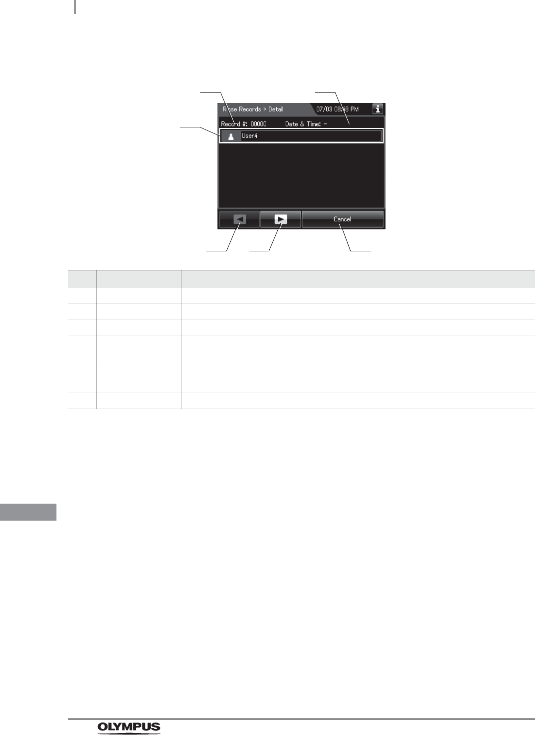
514
11.2 Log display and output
OER-Elite OPERATION MANUAL
Ch.11
(b) Record details – Normal
No. Item/Button Description
1 Record # Number given to each record in the order of occurrence.
2 Date & Time Date and time of completion of rinse.
3 User name Name of user who performed rinse.
4 Previous page
button
Press to show the former record. When there is no further page to turn back to, the
button turns gray and becomes unavailable.
5 Next page button Press to show the later record. When there is no further page to go forward to, the
button turns gray and becomes unavailable.
6 Cancel button Returns to record list.
3
4 5 6
1 2
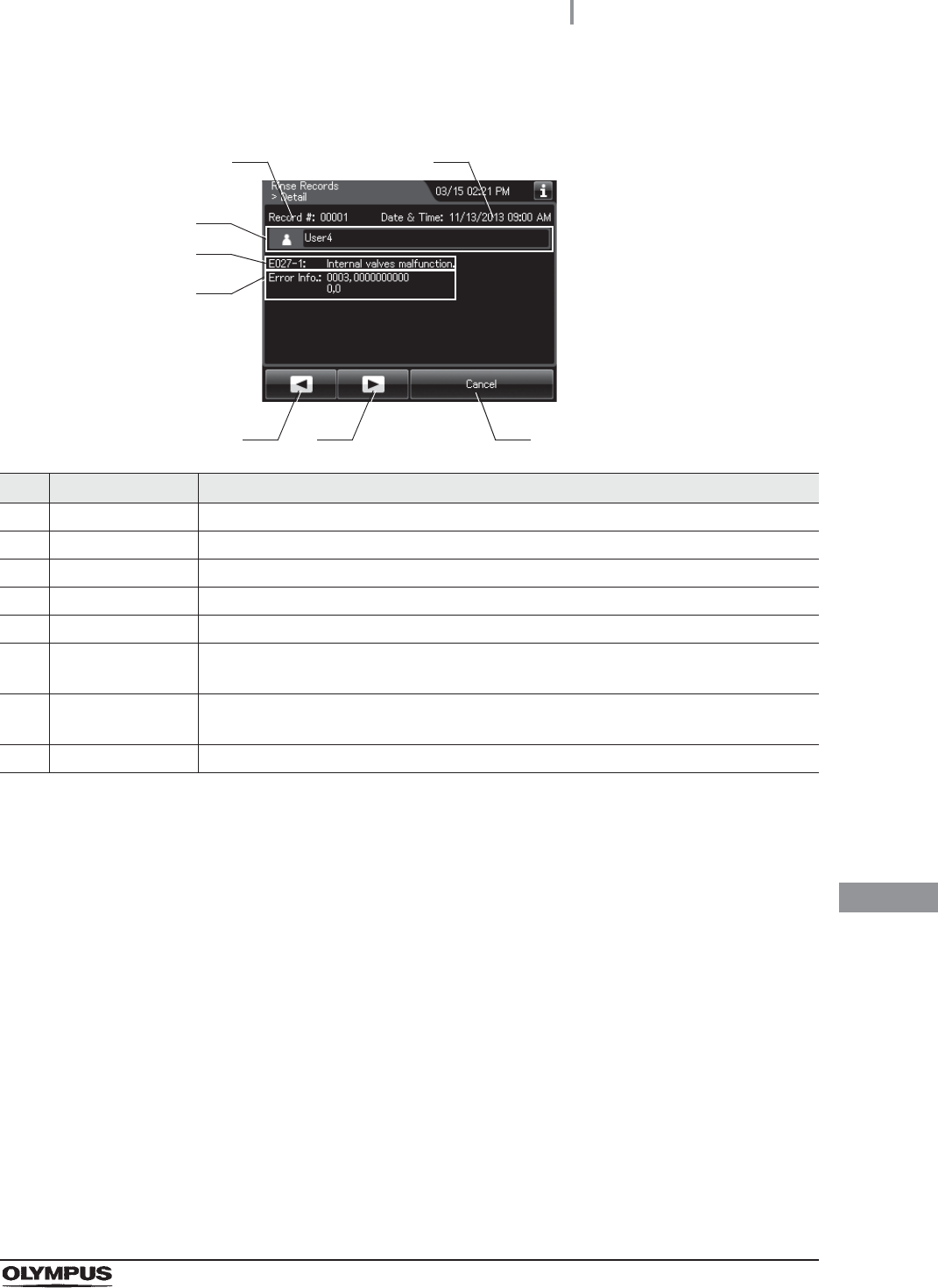
11.2 Log display and output
515
OER-Elite OPERATION MANUAL
Ch.11
(c) Record details – Error
No. Item/Button Description
1 Record # Number given to each record in the order of occurrence.
2 Date & Time Date and time of occurrence of error.
3 User name Name of user who performed rinse.
4 Error code Error code, error details.
5 Error info. Information required for contacting Olympus.
6 Previous page
button
Press to show the former record. When there is no further page to turn back to, the
button turns gray and becomes unavailable.
7 Next page button Press to show the later record. When there is no further page to go forward to, the
button turns gray and becomes unavailable.
8 Cancel button Returns to record list.
3
6 7
4
8
5
1 2

516
11.2 Log display and output
OER-Elite OPERATION MANUAL
Ch.11
Air Purge Records
(a) Record list
No. Item/Button Description
1 Record # Number given to each record in the order of performing air purge.
2 Date & Time Date and time of completion of air purge.
3 Result Result of air purge.
4 Record # button Press to check the details of each record.
5 Previous page
button
Press to show the former record. When there is no further page to turn back to, the
button turns gray and becomes unavailable.
6 Next page button Press to show the later record. When there is no further page to go forward to, the
button turns gray and becomes unavailable.
7 Export button Press to send the entire data items in the record of the selected range to the portable
memory.
8 Cancel button Returns to the viewing range selection screen.
1
5 7
2 3
4
6 8

11.2 Log display and output
517
OER-Elite OPERATION MANUAL
Ch.11
(b) Record details – Normal
No. Item/Button Description
1 Record # Number given to each record in the order of occurrence.
2 Date & Time Date and time of completion of air purge.
3 User name Name of user who performed air purge.
4 Previous page
button
Press to show the former record. When there is no further page to turn back to, the
button turns gray and becomes unavailable.
5 Next page button Press to show the later record. When there is no further page to go forward to, the
button turns gray and becomes unavailable.
6 Cancel button Returns to record list.
3
4 5 6
1 2

518
11.2 Log display and output
OER-Elite OPERATION MANUAL
Ch.11
(c) Record details – Error
No. Item/Button Description
1 Record # Number given to each record in the order of occurrence.
2 Date & Time Date and time of occurrence of error.
3 User name Name of user who performed air purge.
4 Error code Error code, error details.
5 Error info. Information required for contacting Olympus.
6 Previous page
button
Press to show the former record. When there is no further page to turn back to, the
button turns gray and becomes unavailable.
7 Next page button Press to show the later record. When there is no further page to go forward to, the
button turns gray and becomes unavailable.
8 Cancel button Returns to record list.
3
6 7
4
8
5
1 2

11.2 Log display and output
519
OER-Elite OPERATION MANUAL
Ch.11
Alcohol Flush Records
(a) Record list
No. Item/Button Description
1 Record # Number given to each record in the order of performing alcohol flush.
2 Date & Time Date and time of completion of alcohol flush.
3 Result Result of alcohol flush.
4 Record # button Press to check the details of each record.
5 Previous page
button
Press to show the former record. When there is no further page to turn back to, the
button turns gray and becomes unavailable.
6 Next page button Press to show the later record. When there is no further page to go forward to, the
button turns gray and becomes unavailable.
7 Export button Press to send the entire data items in the record of the selected range to the portable
memory.
8 Cancel button Returns to the viewing range selection screen.
1
5 7
2 3
4
6 8
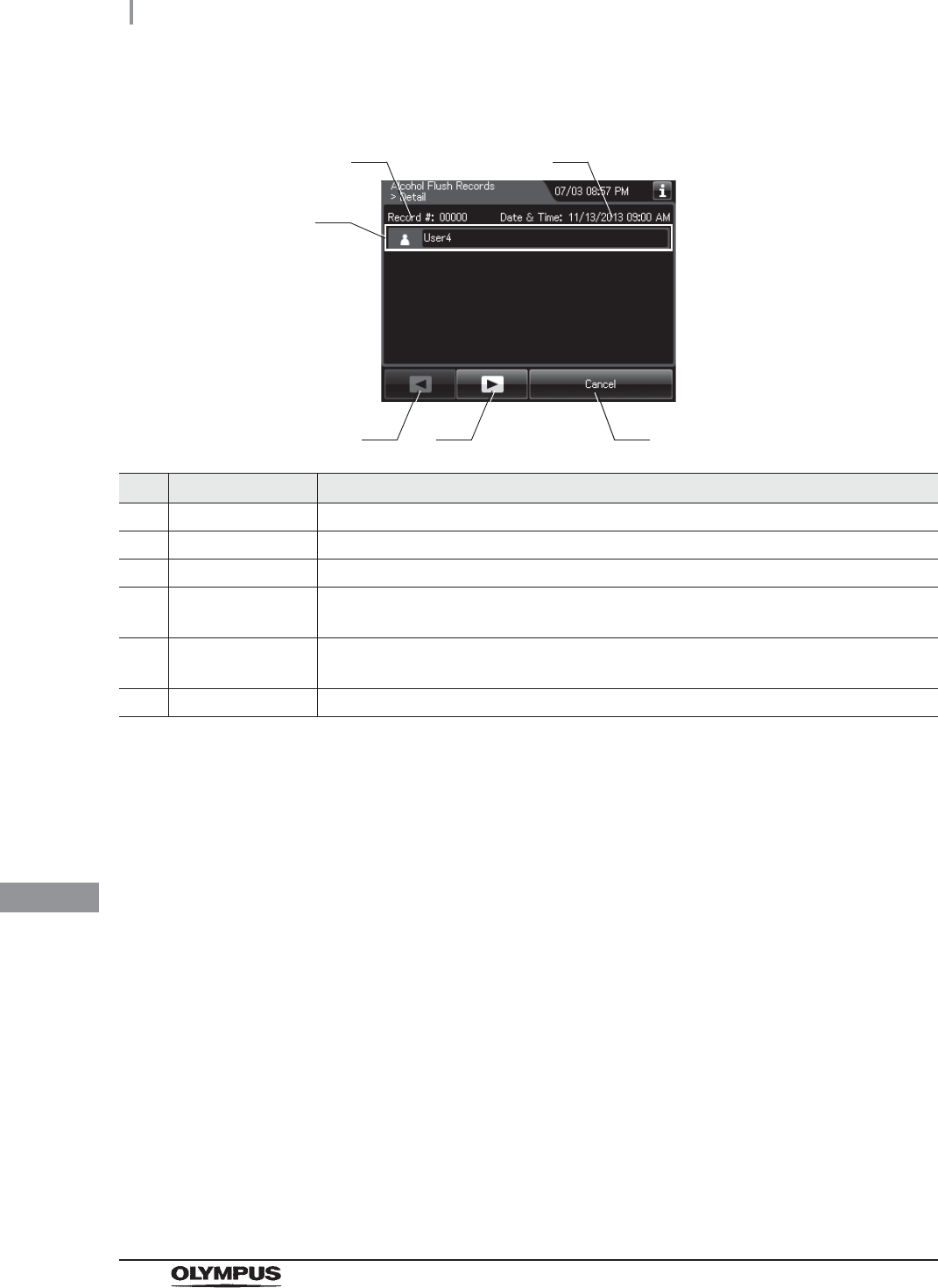
520
11.2 Log display and output
OER-Elite OPERATION MANUAL
Ch.11
(b) Record details – Normal
No. Item/Button Description
1 Record # Number given to each record in the order of occurrence.
2 Date & Time Date and time of completion of alcohol flush.
3 User name Name of user who performed alcohol flush.
4 Previous page
button
Press to show the former record. When there is no further page to turn back to, the
button turns gray and becomes unavailable.
5 Next page button Press to show the later record. When there is no further page to go forward to, the
button turns gray and becomes unavailable.
6 Cancel button Returns to record list.
3
4 5 6
1 2

11.2 Log display and output
521
OER-Elite OPERATION MANUAL
Ch.11
(c) Record details – Error
No. Item/Button Description
1 Record # Number given to each record in the order of occurrence.
2 Date & Time Date and time of occurrence of error.
3 User name Name of user who performed alcohol flush.
4 Error code Error code, error details.
5 Error info. Information required for contacting Olympus.
6 Previous page
button
Press to show the former record. When there is no further page to turn back to, the
button turns gray and becomes unavailable.
7 Next page button Press to show the later record. When there is no further page to go forward to, the
button turns gray and becomes unavailable.
8 Cancel button Returns to record list.
3
6 7
4
8
5
1 2
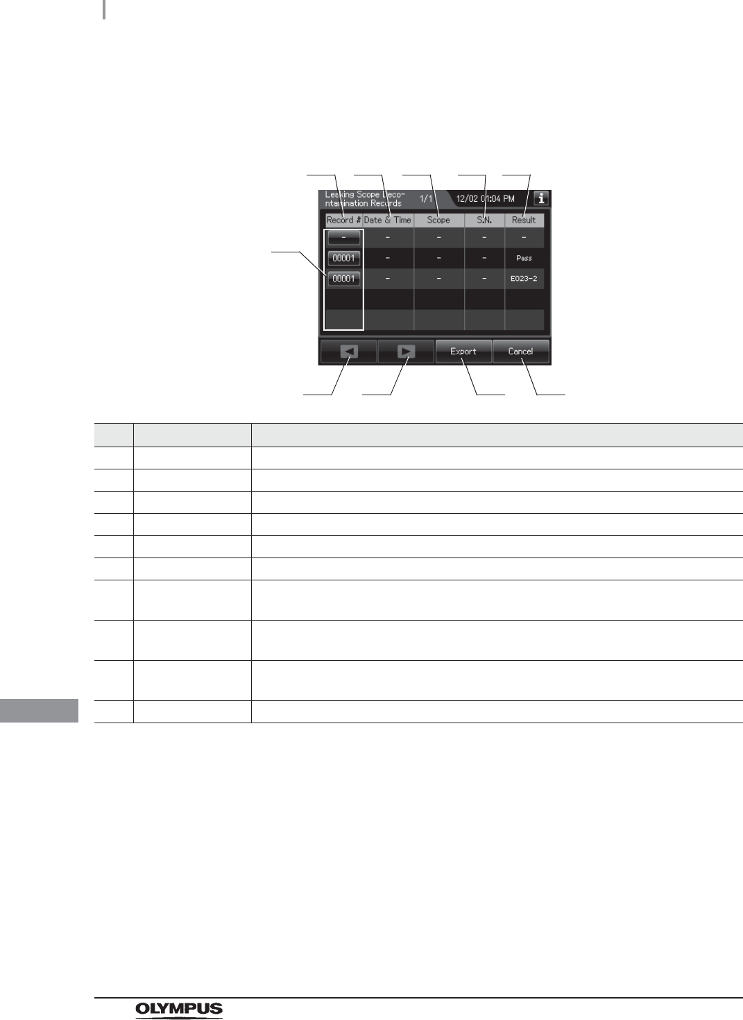
522
11.2 Log display and output
OER-Elite OPERATION MANUAL
Ch.11
Leaking Scope Decontamination Records
(a) Record list
No. Item/Button Description
1 Record # Number given to each record in the order of performed leaking scope decontamination.
2 Date & Time Date and time of completion of leaking scope decontamination.
3 Scope Model number of endoscopes.
4 S.N. Serial number of endoscopes.
5 Result Result of leaking scope decontamination.
6 Record # button Press to check the details of each record.
7 Previous page
button
Press to show the former record. When there is no further page to turn back to, the
button turns gray and becomes unavailable.
8 Next page button Press to show the later record. When there is no further page to go forward to, the
button turns gray and becomes unavailable.
9 Export button Press to send the entire data items in the record of the selected range to the portable
memory.
10 Cancel button Returns to the viewing range selection screen.
1
7 9
2 3 4 5
6
810
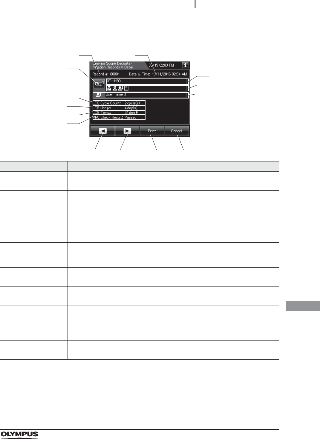
11.2 Log display and output
523
OER-Elite OPERATION MANUAL
Ch.11
(b) Record details – Normal
No. Item/Button Description
1 Record # Number given to each record in the order of occurrence.
2 Date & time Date and time of completion of leaking scope decontamination.
3 Scope button Press to check the ID information related to the endoscope. For detail, refer to
“Confirmation of the input ID” on page 64.
4 Scope model
number
Model number of endoscope.
5 ID status of scope Displays the input status of patient ID, physician ID, user ID (load), and procedure ID
associated with the scope.
6 User name (End of
leaking scope
decontamination)
Name of user who removed the endoscope.
7 LCG Cycle Count Usage count of the disinfectant solution.
8 LCG Usage Number of days that have elapsed since preparation of the disinfectant solution.
9 LCG Temp. Temperature of disinfectant solution at the end of heating.
10 MRC Check Result Input result of MRC check.
11 Previous page
button
Press to show the former record. When there is no further page to turn back to, the
button turns gray and becomes unavailable.
12 Next page button Press to show the later record. When there is no further page to go forward to, the
button turns gray and becomes unavailable.
13 Print button Press to print the record on the optional printer.
14 Cancel button Returns to record list.
3
11 12 13
1 2
14
4
7
8
5
6
9
10

524
11.2 Log display and output
OER-Elite OPERATION MANUAL
Ch.11
(c) Record details – Error
No. Item/Button Description
1 Record # Number given to each record in the order of occurrence.
2 Date & time Date and time of occurrence of error.
3 Scope button Press to check the ID information related to the endoscope.
4 Scope model
number
Model number of endoscope.
5 ID status of scope Displays the input status of patient ID, physician ID, user ID (load), and procedure ID
associated with the scope.
6 Error code Error code, error details.
7 Error Info. Information required for contacting Olympus.
8 Previous page
button
Press to show the former record. When there is no further page to turn back to, the
button turns gray and becomes unavailable.
9 Next page button Press to show the later record. When there is no further page to go forward to, the
button turns gray and becomes unavailable.
10 Print button Press to print the record on the optional printer.
11 Cancel button Returns to record list.
3
8 9 10
1 2
11
4
6
5
7

11.2 Log display and output
525
OER-Elite OPERATION MANUAL
Ch.11
ALT Self-Check Records
(a) Record list
No. Item/Button Description
1 Record # Number given to each record in the order of performing ALT self check.
2 Date & Time Date and time of completion of ALT self check.
3 Result Result of ALT self check.
4 Record # button Press to check the details of each record.
5 Previous page
button
Press to show the former record. When there is no further page to turn back to, the
button turns gray and becomes unavailable.
6 Next page button Press to show the later record. When there is no further page to go forward to, the
button turns gray and becomes unavailable.
7 Export button Press to send the entire data items in the record of the selected range to the portable
memory.
8 Cancel button Returns to the viewing range selection screen.
1
5 7
2 3
4
6 8

526
11.2 Log display and output
OER-Elite OPERATION MANUAL
Ch.11
(b) Record details – Normal
No. Item/Button Description
1 Record # Number given to each record in the order of occurrence.
2 Date & Time Date and time of completion of ALT self check.
3 User name Name of user who performed ALT self check.
4 Result Result of ALT self check.
5 Atmospheric
pressure
Atmospheric pressure during ALT self check.
6 Previous page
button
Press to show the former record. When there is no further page to turn back to, the
button turns gray and becomes unavailable.
7 Next page button Press to show the later record. When there is no further page to go forward to, the
button turns gray and becomes unavailable.
8 Cancel button Returns to record list.
3
6 7 8
1 2
4
5

11.2 Log display and output
527
OER-Elite OPERATION MANUAL
Ch.11
(c) Record details – Error
No. Item/Button Description
1 Record # Number given to each record in the order of occurrence.
2 Date & Time Date and time of occurrence of error.
3 User name Name of user who performed ALT self check.
4 Error code Error code, error details.
5 Error info. Information required for contacting Olympus.
6 Previous page
button
Press to show the former record. When there is no further page to turn back to, the
button turns gray and becomes unavailable.
7 Next page button Press to show the later record. When there is no further page to go forward to, the
button turns gray and becomes unavailable.
8 Cancel button Returns to record list.
3
6 7
4
8
5
1 2
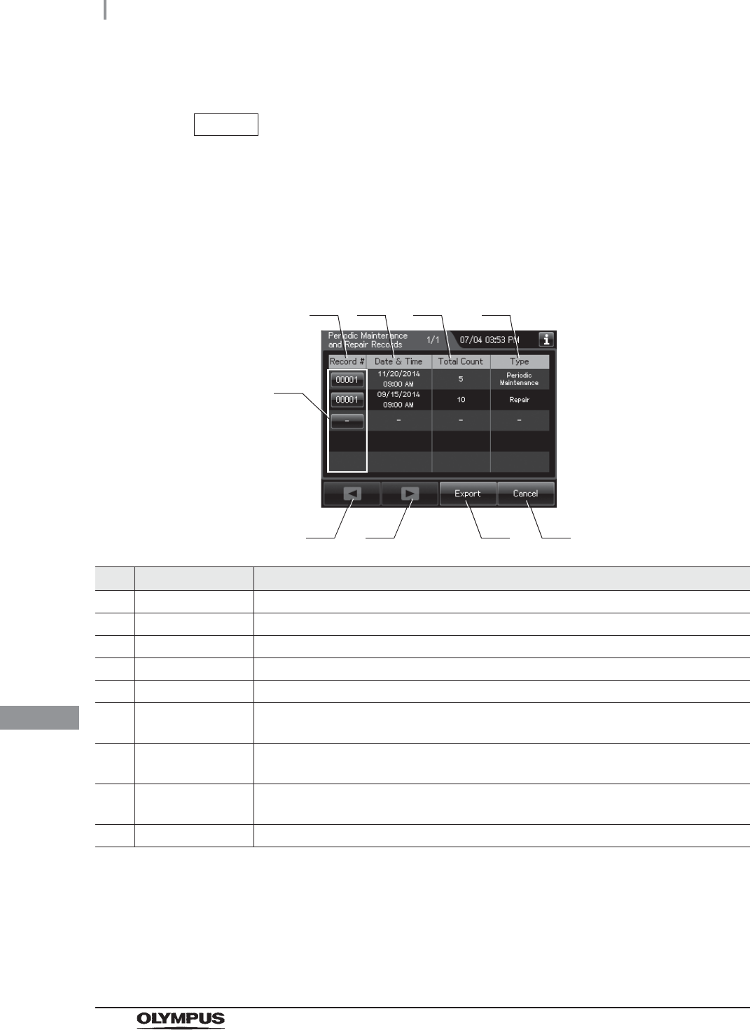
528
11.2 Log display and output
OER-Elite OPERATION MANUAL
Ch.11
Periodic Maintenance and Repair Records
NOTE
• These records are created when maintenance and repair is performed by
OLYMPUS service.
• There records are not matched the actual records in some cases.
(a) Record list
No. Item/Button Description
1 Record # Number given to each record in the order of periodic maintenance and repair.
2 Date & Time Date and time of completion of periodic maintenance and repair.
3 Total Count Total count of reprocessing process the reprocessor has performed.
4 Type Type (Periodic Maintenance or Repair).
5 Record # button Press to check the details of each record.
6 Previous page
button
Press to show the former record. When there is no further page to turn back to, the
button turns gray and becomes unavailable.
7 Next page button Press to show the later record. When there is no further page to go forward to, the
button turns gray and becomes unavailable.
8 Export button Press to send the entire data items in the record of the selected range to the portable
memory.
9 Cancel button Returns to the viewing range selection screen.
1
6 8
2 3 4
5
7 9

11.2 Log display and output
529
OER-Elite OPERATION MANUAL
Ch.11
(b) Record details
No. Item/Button Description
1 Record # Number given to each record in the order of occurrence.
2 Date & time Date and time of completion of periodic maintenance and repair.
3 Name Name who performed periodic maintenance and repair.
4 Type Type (Periodic Maintenance or Repair).
5 Total Cycle Count Total count of reprocessing process the reprocessor has performed.
6 Scheduled Schedule of next periodic maintenance (PM).
7 Previous page
button
Press to show the former record. When there is no further page to turn back to, the
button turns gray and becomes unavailable.
8 Next page button Press to show the later record. When there is no further page to go forward to, the
button turns gray and becomes unavailable.
9 Cancel button Returns to record list.
3
7 8
4
9
5
1 2
6

530
11.2 Log display and output
OER-Elite OPERATION MANUAL
Ch.11
Portable Memory Records
(a) Record list
No. Item/Button Description
1 Record # Number given to each record in the order of exporting to portable memory.
2 Date & Time Date and time of completion of exporting to portable memory.
3 Result Result of exporting to a portable memory.
4 Record # button Press to check the details of each record.
5 Previous page
button
Press to show the former record. When there is no further page to turn back to, the
button turns gray and becomes unavailable.
6 Next page button Press to show the later record. When there is no further page to go forward to, the
button turns gray and becomes unavailable.
7 Export button Press to send the entire data items in the record of the selected range to the portable
memory.
8 Cancel button Returns to the viewing range selection screen.
1
5 7
2 3
4
6 8
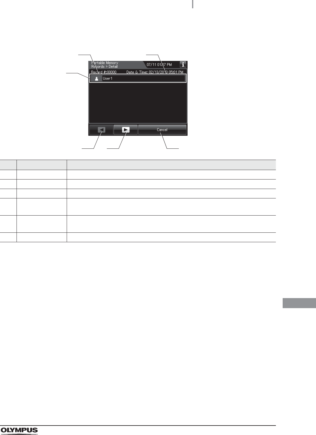
11.2 Log display and output
531
OER-Elite OPERATION MANUAL
Ch.11
(b) Record details – Normal
No. Item/Button Description
1 Record # Number given to each record in the order of occurrence.
2 Date & Time Date and time of completion of exporting to a portable memory.
3 User name Name of user who exported to a portable memory.
4 Previous page
button
Press to show the former record. When there is no further page to turn back to, the
button turns gray and becomes unavailable.
5 Next page button Press to show the later record. When there is no further page to go forward to, the
button turns gray and becomes unavailable.
6 Cancel button Returns to record list.
3
4 5 6
1 2

532
11.2 Log display and output
OER-Elite OPERATION MANUAL
Ch.11
(c) Record details – Error
No. Item/Button Description
1 Record # Number given to each record in the order of occurrence.
2 Date & Time Date and time of occurrence of error.
3 User name Name of user who exporting to a portable memory.
4 Error code Error code, error details.
5 Error info. Information required for contacting Olympus.
6 Previous page
button
Press to show the former record. When there is no further page to turn back to, the
button turns gray and becomes unavailable.
7 Next page button Press to show the later record. When there is no further page to go forward to, the
button turns gray and becomes unavailable.
8 Cancel button Returns to the viewing range selection screen.
3
6 7
4
8
5
1 2

11.3 Log management with PC
533
OER-Elite OPERATION MANUAL
Ch.11
The record data can be saved in a MAJ-1925 portable memory. The output data be opened with a PC
spreadsheet program supporting. CSV file formats.
CAUTION
• The portable memory must be formatted on this reprocessor. If it is formatted on a
PC, etc., recording and playback may be impossible.
• Handle the portable memory. Otherwise, the portable memory and/or the internal
data may be destroyed.
• Do not place the portable memory in a place subjected to strong static electricity,
electromagnetic wave, magnetism, high temperature, high humidity, or corrosive
atmosphere. Otherwise, the portable memory and/or the internal data may be
damaged.
• Do not touch the portable memory with a wet hand. Otherwise, the portable
memory may fail.
• Do not allow the portable memory to come in contact with water. Otherwise, the
portable memory may be damaged.
• Attention should be paid to handling of containing data of patient information.
Otherwise, data leak may result.
• Do not use a portable memory other than one validated by Olympus. Otherwise,
malfunction may result.
• The portable memory is projected slightly from this reprocessor when it is attached.
Do not to apply impact to it. Otherwise, the portable memory and/or data may be
destroyed. Also, remove the portable memory when it is not to be used.
• When malfunction of the internal memory of the reprocessor occurs, the reliability
and validity of the data cannot be guaranteed. It is recommended to export to the
portable memory on a daily basis.
• Pay attention to handle the portable memory and printed paper that include patient
information exported from the OER-Elite.
• It may take additional time to export (e.g.: several months). Also when malfunction
of the internal memory occurs, the reliability and validity of the data cannot be
guaranteed. It is recommended to perform the export to the PORTABLE MEMORY
on a daily basis.
11.3 Log management with PC
534
11.3 Log management with PC
OER-Elite OPERATION MANUAL
Ch.11
NOTE
• The portable memory is intended for temporary saving of records. If they are to be
stored for a long period, store the data in a PC (long term storage media).
• If there is a large quantity of data, it may take long time to export.
• If the patient ID security setting is activated, the patient data will not be exported to
the portable memory. Refer to Section 4.8, “Patient ID security setting”.
Flow of electronic log management
The electronic management of record data is performed in the flow shown below.
Required item
Table 11.2
1Output of record data to the portable memory.
on page 535
2Record management on PC.
on page 541
Check Required item
Portable memory (MAJ-1925)
PC
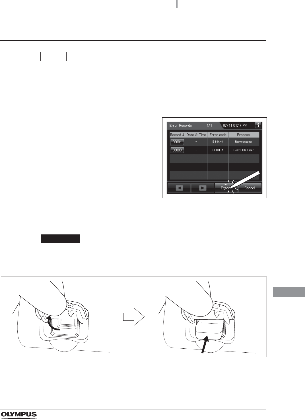
11.3 Log management with PC
535
OER-Elite OPERATION MANUAL
Ch.11
Output of recorded data to the portable memory
NOTE
At least 100 MB capacity is necessary for data export to the portable memory. The
required capacity depends on the data size to be exported.
1Select the record type and viewing range by referring to Section 11.2, “Log display
and output” and display the record list.
2Press the “Export” button on the each record
list screen.
Figure 11.5
3Remove the cover of the portable memory port on the front of the reprocessor and
insert the portable memory all the way into the portable memory port.
CAUTION
Do not remove the cover of the portable memory port on the front of the
reprocessor. Otherwise, water and foreign objects may penetrate the inside of the
portable memory port and cause malfunction of the reprocessor.
Figure 11.6
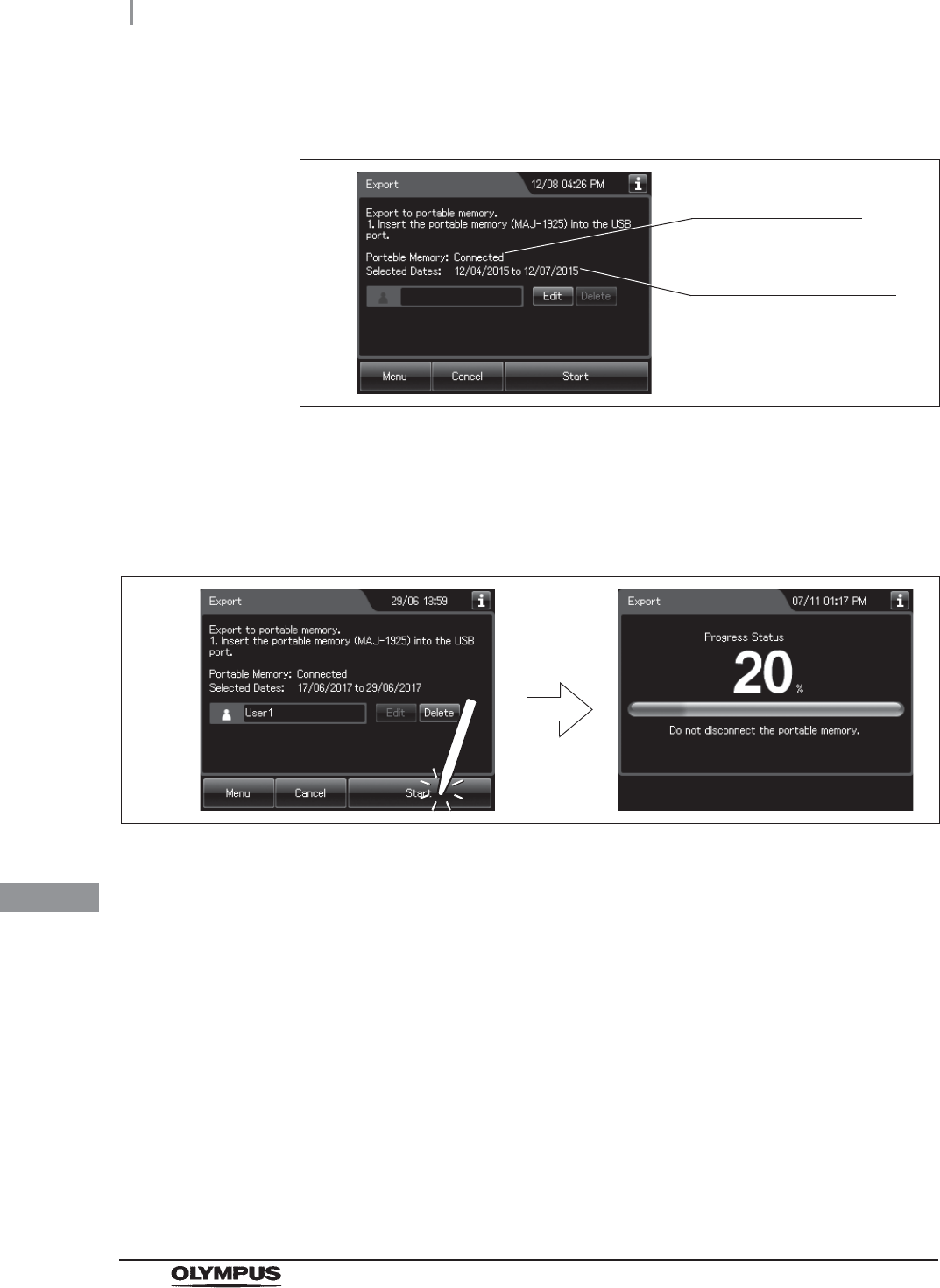
536
11.3 Log management with PC
OER-Elite OPERATION MANUAL
Ch.11
4Confirm that the portable memory connection status screen on the touch screen
changes from “Not Connected” to “Connected”.
Figure 11.7
5Input the user ID. For the detailed procedures, refer to Section 3.6, “Entering ID” (If
applicable).
6Press the “Start” button. The record save operation starts.
Do not disconnect the portable memory during export.
Figure 11.8
Portable memory
connection status
Range of data selected
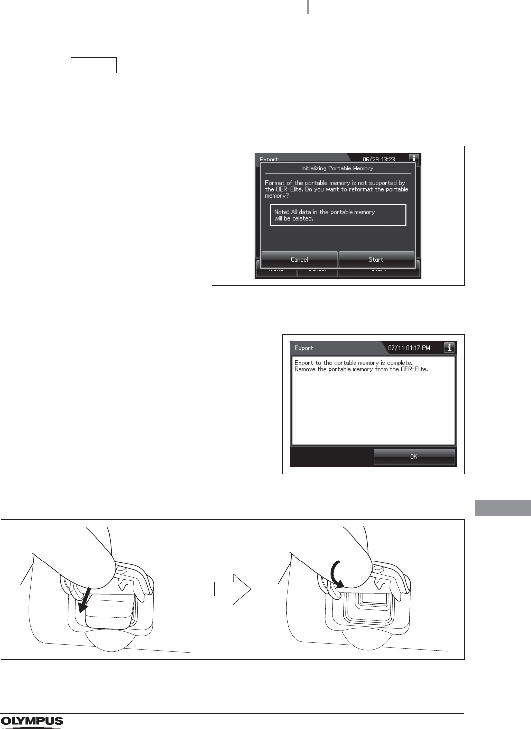
11.3 Log management with PC
537
OER-Elite OPERATION MANUAL
Ch.11
NOTE
If the portable memory has not been formatted, the portable memory formatting
confirmation screen displays a screen as shown in the following figure. To format
the portable memory, refer to “If portable memory has not been formatted” on
page 539.
Figure 11.9
7When the save operation completes, the
following screen appears.
Figure 11.10
8Remove the portable memory by pulling it straight and replace the cover.
Figure 11.11
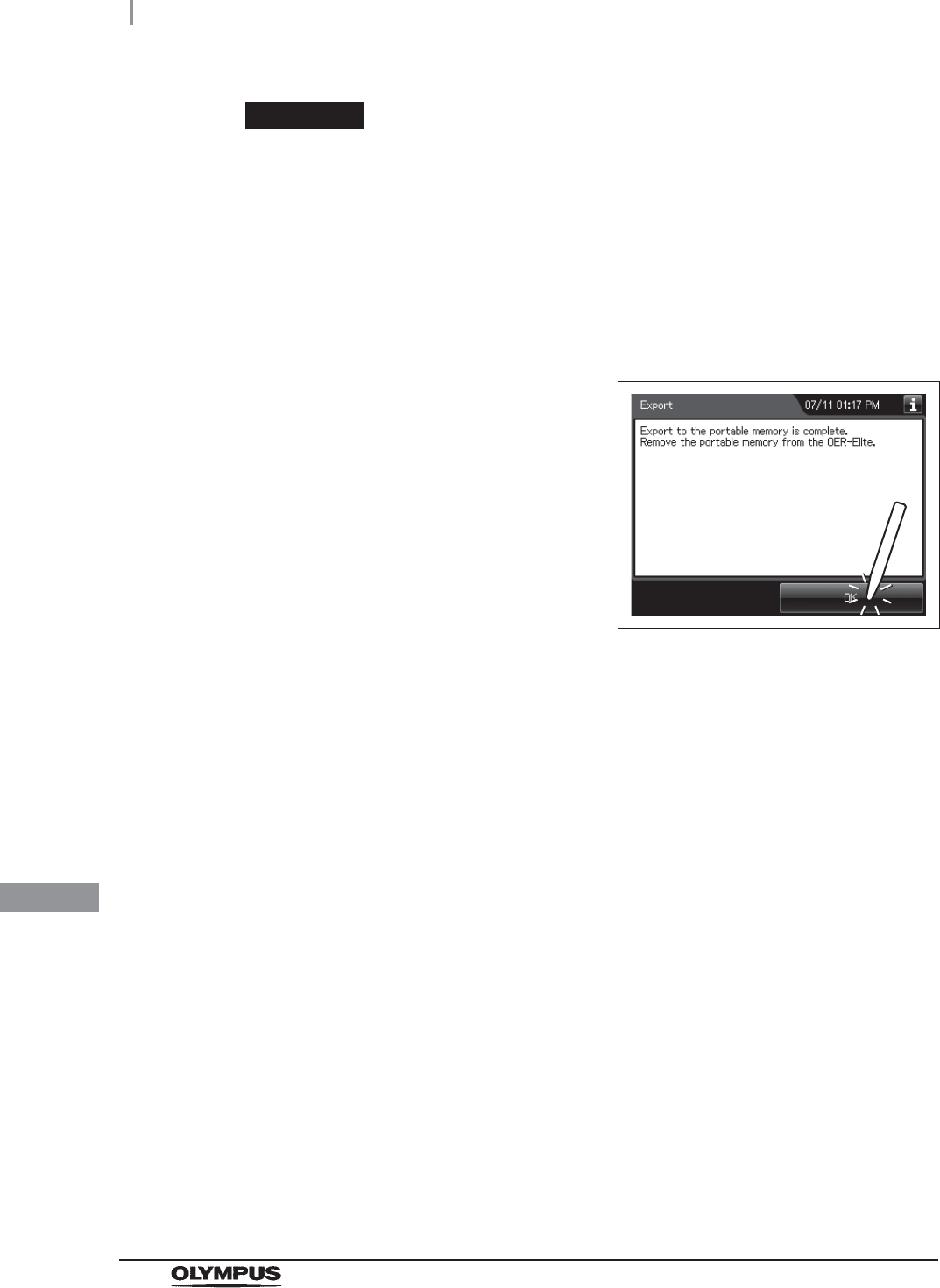
538
11.3 Log management with PC
OER-Elite OPERATION MANUAL
Ch.11
CAUTION
• Do not leave the potable port cover open after the potable memory is removed
from the reprocessor. Otherwise, water and foreign objects may penetrate the
inside of the portable memory port and cause malfunction of the reprocessor.
• Do not allow a foreign object to penetrate the inside of the portable memory port.
The reprocessor may be damaged.
• Do not drop or give any impact to the portable memory. The memory or data may
be damaged. Also, remove the portable memory when it is not used.
9Press the “OK” button to finish.
Figure 11.12
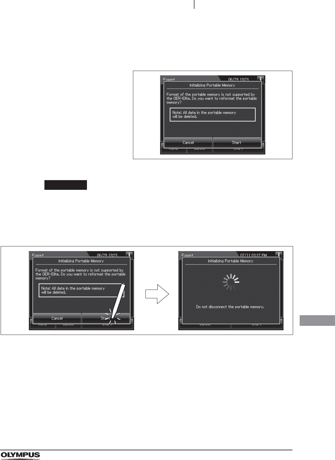
11.3 Log management with PC
539
OER-Elite OPERATION MANUAL
Ch.11
If portable memory has not been formatted
If a portable memory is not supported by OER-Elite, the following screen is displayed at the
moment the “Start” button is pressed to enable data saving in the portable memory.
Figure 11.13
CAUTION
Confirm that important data is not contained before performing the process.
Initializing portable memory delete all data in the portable memory.
1Press the “Start” button on the portable memory formatting confirmation screen. The
formatting starts.
Figure 11.14
540
11.3 Log management with PC
OER-Elite OPERATION MANUAL
Ch.11
2When the formatting completes, the following
screen appears.
Figure 11.15
3Press the “OK” button to close the portable
memory formatting confirmation screen.
Figure 11.16
4Go back to Step 6 in “Output of recorded data to the portable memory” on
page 535.
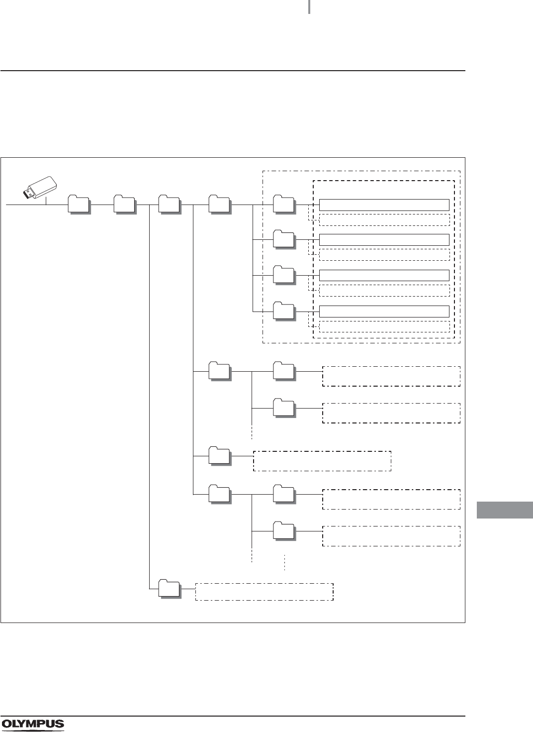
11.3 Log management with PC
541
OER-Elite OPERATION MANUAL
Ch.11
Log management on PC
Configuration of saved record data
The record data is saved in the portable memory in the hierarchical structure shown below. This
record data is sample information.
Figure 11.17
1st
Level
Reprocessing
Room
OER-Elite
BackUp
Reprocessing All
2nd
Level
3rd
Level
Work
Function (process name)
4th
Level
SetPeriod
5th
Level
All Data 7/4/2013
All Data 7/5/2013
Set Period From 7/4/2013 to 7/5/2013
Set Period From 7/5/2013 to 7/6/2013
SetMonth
Set Month From June, 2013.
Set Month From July, 2013.
Differential
USB memory unoutput 7/4/2013
Error
Replacement
of Consumable
Items
(Consumable Item)
USB memory unoutput 7/5/2013
Same as Reprocessing folder
(process name)
Same as Reprocessing folder
(Consumable Item)
Same as Reprocessing folder
Same as Reprocessing folder
Same as Reprocessing folder
Same as Work folder
CSV Files
542
11.3 Log management with PC
OER-Elite OPERATION MANUAL
Ch.11
CAUTION
Do not modify any data inside “BackUp” folder. It is defined as master data after it
transferred to PC. The master data inside “BackUp” folder is recommended in order
to maintain the reliability and validity of any data. To properly manage master data
inside “BackUp” folder so that the master data is not edited on PC.
NOTE
Two same files are recorded in “Back Up” folder and “Work” folder. The data inside
“Work” folder can be edited.
(a) Folder hierarchy
1st level: “Reprocessing Room”
The “Reprocessing Room” folder is created.
2nd level: “OER-Elite”
The folder for this reprocessor (“OER-Elite”) is created.
3rd level: “BackUp”, “Work”
The “BackUp” and “Work” folders are created.
The files in the “BackUp” and “Work” folders consist of identical downloaded data.
The files in the “Work” folders are used for the editing.
The files in the “BackUp” folders are master files that should not be altered.
4th level, 5th level: Process category
A folder is created for each process category. For detail of name of each folder, refer to the
following table.