Raytheon IIS ARTU Air-Ground Radio System User Manual installation manual part one
Raytheon Company Air-Ground Radio System installation manual part one
Contents
installation manual part one
FCC ill: CDG-ARTU EXHlBrrc
MAGNASTAR C-2000 DIGITAL AIRBORNE TELEPHONE
INSTAllATION MANUAL
Document Number: 481618
Original Release - September 16, 1994
Rev B August 9, 2000
Copyright @ 1994, 1996, 2000
Raytheon Company
All Rights Reserved
Reproduction of all or parts of this document by MagnaStar Dealers for use in sales, installation,
or maintenance of MagnaStar products is authorized.
FCC ID: CDG-ARTU
MAGNASTAR
EXHIBITC
C-2000 DIGITAL AIRBORNE TELEPHONE SYSTEM
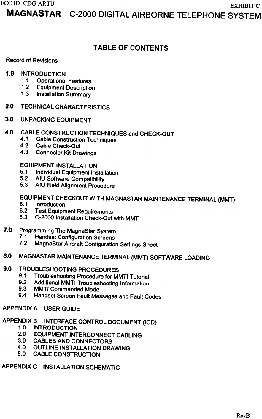
TABLE OF CONTENTS
Record of Revisions
1.0 INTRODUCTION
1.1 Operational Features
1.2 Equipment Description
1.3 Installation Summary
2.0 TECHNICAL CHARACTERISTICS
3.0 UNPACKING EQUIPMENT
4.0 CABLE CONSTRUCTION TECHNIQUES and CHECK-OUT
4.1 Cable Construction Techniques
4.2 Cable Check-Out
4.3 Connector Kit Drawings
EQUIPMENT INSTALLATION
5.1 Individual Equipment Installation
5.2 AIU Software Compatibility
5.3 AIU Field Alignment Procedure
EQUIPMENT CHECKOUT WITH MAGNASTAR MAINTENANCE TERMINAL (MMT)
6.1 Introduction
6.2 Test Equipment Requirements
6.3 C-2000 Installation Check-Out with MMT
7.0 Programming The MagnaStar System
7.1 Handset Configuration Screens
7.2 MagnaStar Aircraft Configuration Settings Sheet
8.0 MAGNASTAR MAINTENANCE TERMINAL (MMT) SOFTWARE LOADING
9.0 TROUBLESHOOTING PROCEDURES
9.1 Troubleshooting Procedure for MMTI Tutorial
9.2 Additional MMTI Troubleshooting Information
9.3 MMTI Commanded Mode
9.4 Handset Screen Fault Messages and Fault Codes
APPENDIX A USER GUIDE
APPENDIX B INTERFACE CONTROL DOCUMENT (ICD)
1.0 INTRODUCTION
2.0 EQUIPMENT INTERCONNECT CABLING
3.0 CABLES AND CONNECTORS
4.0 OUTLINE INSTALLATION DRAWING
5.0 CABLE CONSTRUCTION
APPENDIX C INSTALLATION SCHEMATIC
RevB
EXHIBITC
C-2000 DIGITAL AI RBORNE TELEPHONE SYSTEM
FCC ill: CDG-ARTU
MAGNASTAR
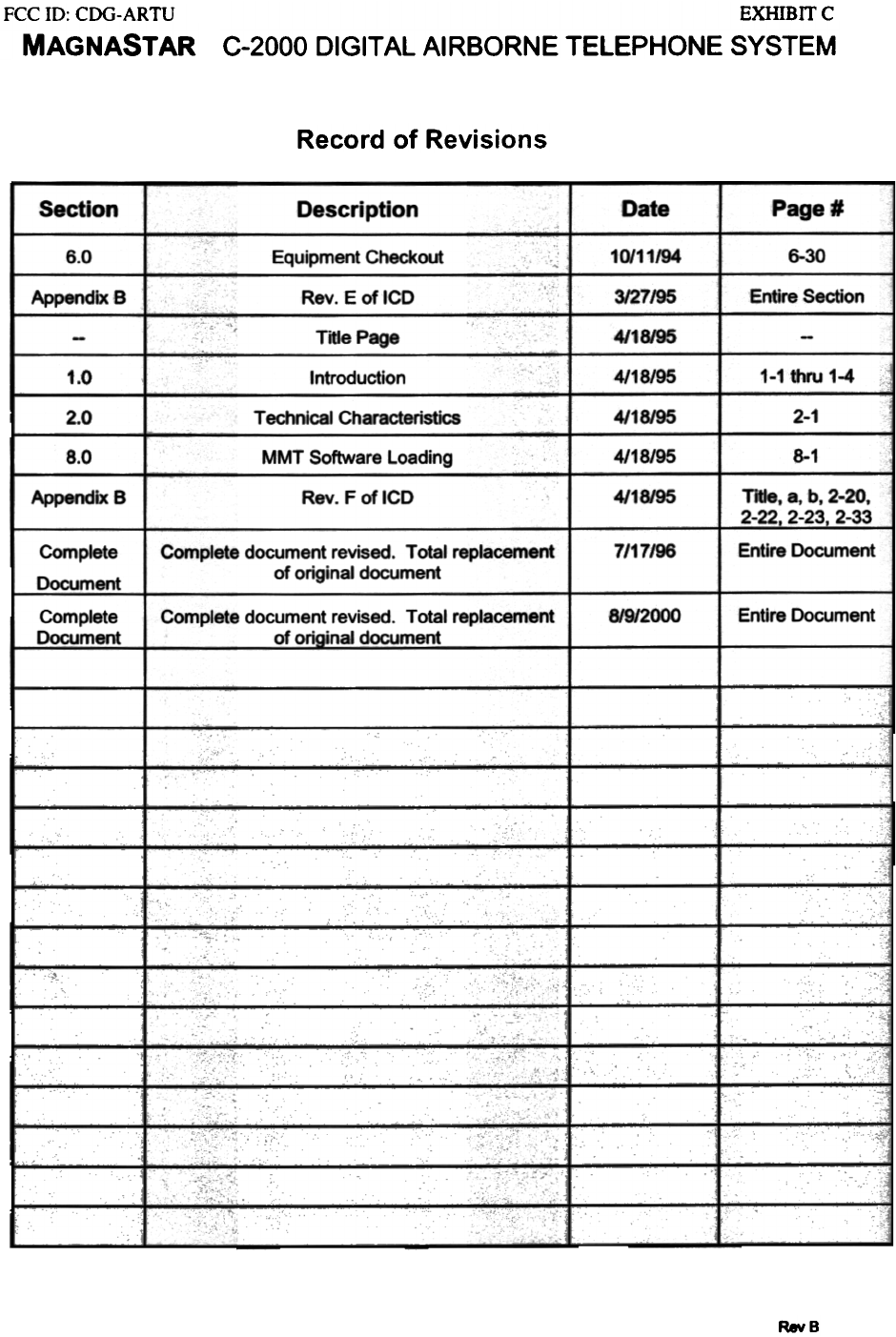
Record of Revisions
Date Page #
Section Description
10/11/94 6-30
6.0 Equipment Checkout
Appendix B Rev. E of ICD 3/27/95 Entire Section
Title Page 4/18/95
4/18/95 1-1 thru 1-4
1.0 Introduction
2.0 4/18/95 2-1
Technical Characteristics
4/18/95 8-1
8.0 MMT Software Loading
4/18/95 Title. 8, b. 2-20.
2-22, 2-23. 2-33
Appendix B Rev. F of ICD
7/17/96
Complete
Document
Complete document revised. Total replacement
of original document Entire Document.
8/9/2000 Entire Document
Complete
Document Complete document revised. Total replacement
of orioinaJ document
RevB
FCC ill: CDG-ARTU
MAGNASTAR
EXHIBITC
C-2000 DIGITAL AIRBORNE TELEPHONE SYSTEM
1.0 INTRODUCTION
The MagnaStar Digital Airborne Telephone System brings complete telephony service to business
and general aviation aircraft. From the GTE Airfone digital air-ground telephone system to SA TCOM
connections, the MagnaStar C-2000 offers a full-featured communications environment.
1.1 Operational Features
The C-2000 system brings the office to the sky. All the communication features required in the
office are made available in the airborne enviromnent. The system has been designed to provide these
features with high quality of service and ease of operation.
Direct Dialing - Callers can dial direct through the North American Public Switched Telephone
Network (PSTN) or to international destinations. Calls can be charged to the
corporate (MagnaStar equipment owner) account (I + dialing) or to major credit
cards (0 + dialing). Of course, operator assisted (0 +) calling is also available.
Continuous North
American Coverage
- The MagnaStar Digital Airborne Telephone operates over the GenStarTM digital
telephone system from GTE Airfone, which offers continuous North American
coverage with automatic cell-to-cell voice-call hand-off without call interruption.
Ground system covernge is available throughout the United States, southern
Canada, and Mexico.
SA TCOM Connection - The MagnaStar system connects to SA TCOM systems, on aircraft so equipped, to
provide easy access and choice of communication link to callers from any cabin
handset. The C-2000 supports both analog interfaces and the digital CEPT-EI
interface to multi-channel SA TCOM systems.
Cabin Management - MagnaStar air-ground communications can be provided to aircraft using
Connection separately supplied cabin management systems. Contact MagnaStar engineering
support on the StarLine at (888-246-ST AR) for further infonnation and specific
interface availability.
Cellular Connection
HF Connection
- The MagnaStar system connects to the Cellular Phone (Cell Phone) System
through the use of a Cell Phone Interface (CPI) to provide easy access to the
Cellular system whenever the aircraft is on the ground.
- The MagnaStar system connects to HF radios, on aircraft so equipped, to provide
easy access to that communication link from any cabin handset. Push-to-talk
(PTT) control is voice activated, eliminating the need for a PTT switch on the
handset.
Multiple Calls - The MagnaStar system allows two simultaneous phone calls of any type (voice,
data, FAX, TDD) over the GenStar system. Additionally, simultaneous calls can
be made through a HF radio and over as many SA TCOM channels as supported
by the appropriate equipment, if so configured.
Uplink Calls - Uplink telephone numbers (or SATCOM "Terminal IOlt numbers) can be
assigned to the aircraft or to each handset. For individuals with an AirCall
number from GTE Airfone and signed on to the system, calls will be routed
directly to their seats. When a call is received, the calling number is displayed
and the called party has the option of accepting the call or not.
MagnaSlar is a trademark of the Raytheon Systems Ccxnpany. GenSIar is a lJademark of GTE Airfone blcorporated.
RevB
FCC ill: CDG-ARTU
MAGNASTAR
EXHIBITC
C-2000 DIGITAL AIRBORNE TELEPHONE SYSTEM
Conference Calls Conferences can be set up between multiple parties on-board and on the ground,
over any of the available links (GenStar, SATCOM, HF).
Call Transfer Incoming and outgoing calls can be transferred to other handsets on-board the
aircraft.
In-Plane Calls Seat-to-seat (cabin-to-cockpit) calling is a standard feature.
Speed Dialing With the MagnaStar system. callers can store and quickly call frequently called
numbers as well as access services offered by GTE Airfone (hotel, car rental,
weather, etc.).
Multiple Phones The basic C-2000 system allows installation of up to nine independent (non-party-
line) telephone handsets. A system configuration allowing up to fifty handsets is
currently being developed.
Fax I Data Modem The MagnaStar system provides RJ.II jacks for connection of caller's fax or
personal computer modem equipment. The RJ.II jacks are integral to the handset;
they may be remoted so that the fax / modem cable does not interfere with use of
the handset. The system is designed to support high quality (low error rate) voice
band data transmissions at 2400 bps; 4800 bps, and 9600 bps. Higher rate
capabilities are in development by Raytheon and GTE Airfone engineering.
TOO Customer supplied TOO equipment is supported by the MagnaStar system, via the
handset itself or the RJ-II jack.
Call Charging Service charges for calls made with the MagnaStar system are billed directly to
the equipment owner's account (1 + calls) or to credit card accounts (0 + calls).
Direct charged (1 +) calls can be blocked, for example during charter use of the
aircraft.
Privacy The MagnaStar system uses an advanced modulation and signaling scheme which
offers inherent communications privacy. Your conversation is protected from
casual listening by others having 'scanners' or by even similarly equipped aircraft.
(This privacy is only limited by the normal private-line telephone service through
the PSTN. Additional security can be provided with optional features.)
1-2 RevB
FCC ill: CDG-ARTU
MAGNASTAR EXHIBITC
C-2000 DIGITAL AIRBORNE TELEPHONE SYSTEM
1.2 Equipment Description
The MagnaStar C-2<XX> system is designed with the business aircraft in mind. With two air-
ground voice channel operations as a standard feature, the C-2<XX> consists of an Airborne Radio
Telecommunications Unit (ARTU), an antenna, a duplexer, a mounting tray for the ARTU, one or more
Cabin Data Bus Repeaters (COBRs), and one to nine telephone handsets. Optional equipment includes one
to three Analog Interface Units (AlU), a Call Alerter Switch (CAS), Cell Phone Interface (CPI), Cockpit
Headset Interface Panel (CHIP), and other specialized devices.
A&JJ1: The ARTU provides the private automatic base exchange (P ABX) features, controls the C-2000
system. and contains the receiver-transmitter functions for radio transmission. This digital radio has been
implemented using state-of-the-art multiple digitaJ signal processor techniques to provide accurate
waveform control and noise-free, reliable communications in the noisy, fading. high-Doppler signal
environment seen in jet aircraft-to-ground communications. Reliability is further enhanced by the
automated assembly and test techniques used to manufacture the high density surface-mount-device circuit
cards. Should any problem occur, built-in-test identifies the source of the problem for quick circuit card
replacement and return of the unit to service.
Antenna / D~lexer: The antenna is a low drag, quarter wavelength design swtable for use on high
perforDJance jet aircraft. The duplexer is a passive signal filter-combiner that combines the receive and
transmit lines to the common antenna.
~: The data and control interface to the ARTU is by means of a high speed time division multiplexed
digital bus operating as a local area network (LAN). User interface devices such as handsets, fax machines,
modems, etc. connect to the system via this LAN. There are two different nx>dels of the CDBR. The
CDBR-l (~ell) provides for physical connection of up to two digital handsets (with their RJ-ll jacks
for the fax I modem connections) to the LAN bus. The CDBR-2 (model 2) provides two analog interface
connections, each of which can support either a four wire analog handset or two wire data for direct
connection of a fax machine or modem Additionally, the CDBR-2 provides a separate interface for
connection of a digital handset.
Di2ital Handset: The telephone handsets have been selected for performance and reliability. The handsets
contain noise-canceling microphones to overco~ the aircraft noise environment; audio is digitized at the
handset to further ensure clear communication. Special function keys and a liquid crystal display allow
easy use of all options available to the user. The digital handsets are offered with varied mounting
provisions to fit any installation requirement. Handsets are offered with a) a standard build-in style mount
to hold the handset when not in use, with a ratcheting cord reel, b) that version with a bulkhead mounting
adapter, c) the handset and cord reel without a mount, for custom mounting, and d) a "curly-cord" (like
standard office phones) with a plug for the ability to relocate the handset to various locations wired with the
matching jack. Variations a - c also are available with the RJ-ll jack remoted from the handset, to be
located where it best fits in the interior design of the aircraft. All variations come in four colors: white,
platinum, pepper dust, and black. Develop~nt is on-going for additional telephone handset options.
AllJ.: The AIU can be used to connect an analog SA TCOM unit, a Cel1 Phone Interface (CPI), a HF radio,
or a Public Address (P A) amplifier, and/or other communications devices to the MagnaStar system The
AIU bas been designed with electrical interfaces to optimize the connection to any analog-interface
SA TCOM system selected by the custo~. Separate connections are provided to accotmt for variations in
audio-line impedance and level and in the hook switch and status interfaces between SATCOM equip~nt.
HF radio connections can be made directly or through the aircraft audio control panel. The varying
requirements for the SA TCOM and HF interfaces led to an AIU design that offers the flexibility to connect
a wide variety of equip~nt and systems to the C-2000. AIUs interface to the ARTU over the LAN, like
the COORs.
RevB
1-3
FCC ID: CDG-ARTU
MAGNASTAR
EXHIBITC
C-2000 DIGITAL AIRBORNE TELEPHONE SYSTEM
~: The CAS provides ten switches to control call alerting devices (supplied by the installer) such as
bells, lights, cabin chime, etc. (Even in the relatively noise-quieted cabins of business jets, the ambient
noise can make it difficult to hear the electronic ringer of the standard handset. Increasing the volume of
the handset speaker could be annoying should the handset be close to a user's ear when it rang. A separate
alerter avoids this problem and allows for installation of the handsets in enclosed compartments.) Single or
multiple switches can be assigned to a handset and to multiple handsets; and the cadence of the "ring"
pattern can be controlled, giving a great deal of flexibility to customize uplink call notification. One CAS
is used per aircraft; it connects to a digital handset port of any of the CDBRs in the system. The CAS may
also be used to signal when Air-Ground, SA TCOM or HF services are available or when one or more
particular handsets are in use.
Miscellaneous: The MagnaStar system can interface to many other communications equipment. The
"-802" modification to the ARTU provides a CEPT -EI interface to connect directly to SA TCOM systems
or to cabin management equipment. The flexibility is built in to the system to accommodate customer-
unique requirements with minimum new development.
1.3 Installation Summary
The ARTU is installed in an ARINC style mounting tray using two type A hold downs. It is
designed for installation in pressurized or non-pressurized locations. The mounting tray provides an
air plenum and fan for cooling. The fan is quiet enough to allow cabin installation. The duplexer
can be mounted in any convenient location between the ARTU and the antenna. The antenna comes
with a standard six hole mounting flange. As an option, a four hole flange is available for direct
replacement of standard 450 MHz radio telephone antennas. The handsets are designed for
installation in any convenient area of the cabin. Custom mounting provisions can be readily
provided.
Installation information and equipment outline drawings are available in the Interface Control
Document (ICD) Appendix B.
ReYB
-4
FCC 10: CDG-ARTU
MAGNASTAR EXHIBITC
C-2000 DIGITAL AIRBORNE TELEPHONE SYSTEM
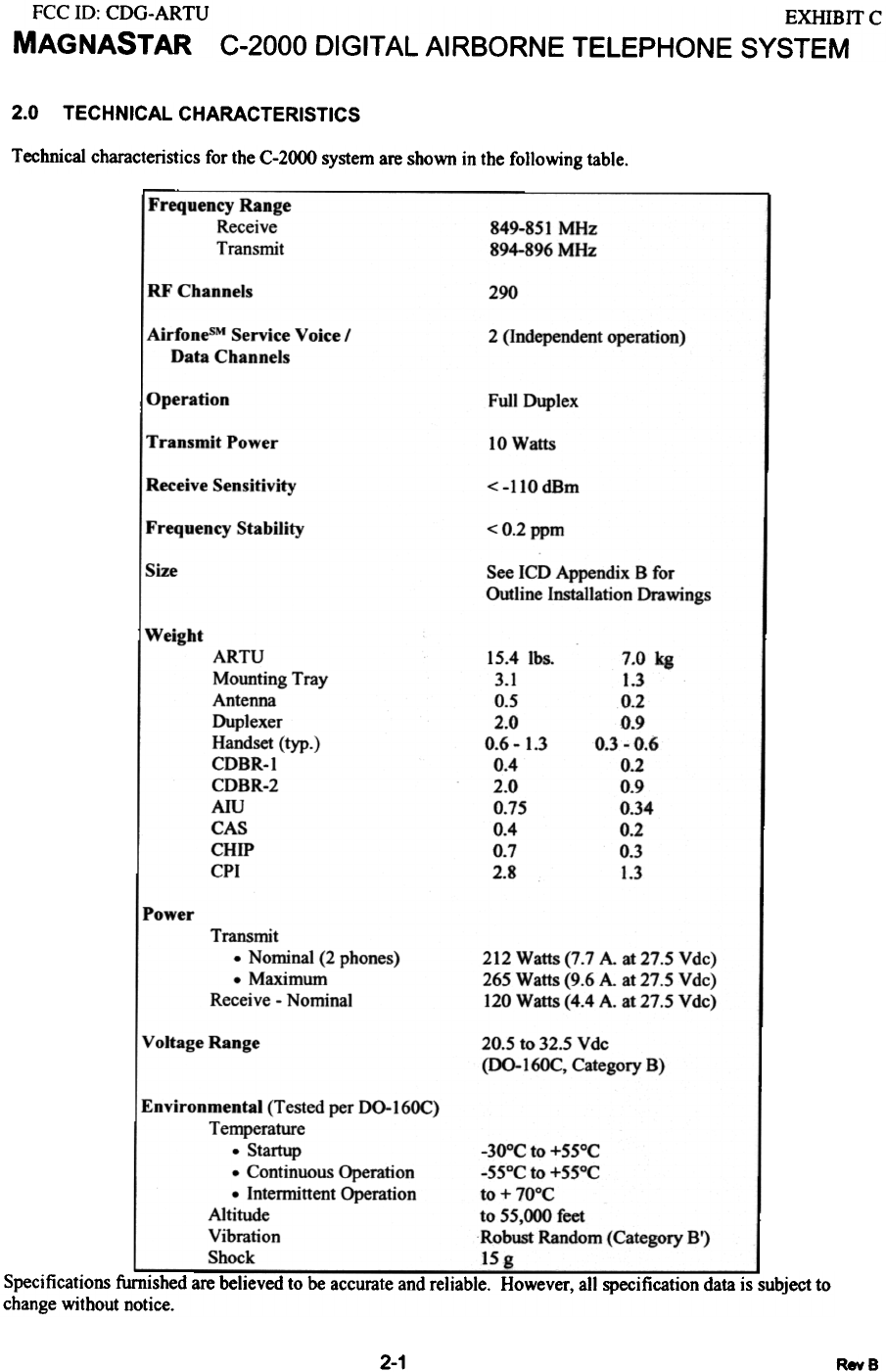
2.0 TECHNICAL CHARACTERISTICS
Technical characteristics for the C-2000 system are shown in the following table.
Frequency Range
Receive
Transmit 849-851 MHz
894-896 MHz
RF Channels 290
AirfonesM Service Voice I
Data Channels 2 (Independent operation)
Operation Full Duplex
Transmit Power 10 Watts
Receive Sensitivity < -110 dBm
Frequency Stability < 0.2 ppm
!Size See ICD Appendix B for
Outline Installation Drawings
Weight
7.0 kg
1.3
0.2
0.9
0.3 - 0.6
0.2
0.9
0.34
0.2
0.3
1.3
ARTU
Mounting Tray
Antenna
Duplexer
Handset (typ.)
CDBR-I
CDBR-2
AIU
CAS
CHIP
CPI
15.4 Ibs
3.1
0.5
2.0
0.6 - 1.3
0.4
2.0
0.75
0.4
0.7
2.8
Power Transmit
- Nominal (2 phones)
-Maximum
Receive - Nominal
212 Watts (7.7 A at 27.5 Vdc)
265 Watts (9.6 A. at 27.5 Vdc)
120 Watts (4.4 A. at 27.5 Vdc)
Voltage Range 20.5 to 32.5 Vdc
(00-16OC, Category B)
Environmental (Tested per 00-16OC)
Temperature
. Startup
. Continuous Operation
. Intemrittent Operation
Altitude
Vibration
Shock
-30°C to +55°C
-55°C to +55°C
to + 70°C
to 55,000 feet
Robust Random (Category Sf)
15 g
Specifications furnished are believed to be accurate and reliable. However, all specification data is subject to
change without notice.
2-1 RevS
.
.B
a
..
~
9
~
fI1
0
0
\D
8
~
!
.
*
R::C ill: CDG-ARTU
§
:I:
~
~~
~~
aJ
~~!:3-
o~
>
~~
~~
u
~~
~~
il
IIJ~
I
~~
I
~IIIJ~
f-< >
I
~!
I~
~
~
;)-
...~
~
-<
g
=-
NO
I ~
U .
<
~
u
-=
~
u
0 -
r"- U
+ on
~
..t
on
on
.
on 0
on E-
+ E-
rn
~
E-
U C
0 Z
~ ~
. -
=
~
~
=
'<
u
CD
3
-
~
3
-<
fI)
a
N
'<
U
?
<
I,;c
u
=
I,;c
u
<
CI)
~
Q
I";'
"'in
V\
...
Q
r;
m
~
CJ
=,.
~
-
~
-=
3
~
~
u
-
~
t:;;
u
N
5
;I~
~
0
~o
U~ .
<
3
=
~
to>
-=
~
u
"'0
1"--
+u on
~
.:t
on
on
I
"in 0
on""
+ CI)
~
- 0
QZ
f';Ie,
-=
~
u
=
~
u
ii5
'<
u
-<
V)
V)
~
u
N
~
CJ
>-
~~
<
f.<
u
-=
f.<
u
=
~
u
~
!(
u
-<
(/)
~
.oJ
U
N
3
-
'-
0
t;a on
~
.:t
on
on
I
onO
~~
~
~
uO
~~
=
'<
u
~
~
u
-0
'";'
~
V)
+
~
+
-~
'.:(
u
-=
~
-<
u
:,..
~
3
=
3
-<
~
<
~
u
s
~
-
~
'=
'<
u
N
~
U
=
'<
u
<
'<
u
~
I ~
0..><
;J~
Q.J
-
~
0
.,
it
g
+
co
8
=
8
=
~
u
-
~
8
N
~
N
5
..,.
-=
~
u
<
'<
u
~
=
Q
U
0
r--.
+
-<
~
(oJ
=
~
CJ
N
rn
j
U
~
.,.
-
~
+
u
3
~
~
u
N
!<
u
~
-.
~
=
~
CJ
<
'<
u
""?"
~
=
Q
U
~
~
+
u
3
<
~
u
=
~
u
~
~
(.)
N
~
~
U
N
3
~
-.
~
-=
~
-<
u
=
3
N
~
~
u
<
~
c.>
"?
0;)
-
-<
-
II..
'k
+
u
5
<
!(
u
N
~
~
~
~
+
~
+
~
-=
~
u
=
...
~
N
~
j
U
<
'.<
u
~
u
~
u
~
u
<
~
u
N
5
=
~
u
<
!:<;
(oJ
~
=
u
'<
VI
-
on
~
0
r-
+
u
3
-<
~
u
CD
~
u
N
CI1
j
U
N
~
"?
:-c;
o~
=
'<
u
=
~
u
<
rI)
a
<
3
~rrc
---
~~
E E
,-,'-'
=N
1-1-
«
UU
Q
~~
=(1)
~
=
~
u
u
5
~~
.s i
i'~
'-',-,
~~
"?"
~
j
~
-<
1
..
~
-
'C
~
's 'B
.- ...
C/) '3
>-g'
~~
~
i
f-
~
~
"8
to:
'u
~
0
f-
'0
u
Q
~
v.
i-
:a
.~
::
~
!)
~
u
~
+
'i
1
f-
~
:a
.~
::
t
>
u
cn
.. ..r
.~
>-
-;
~
~
'c
8
c
"6b
c
UJ
>-
~
..,
~
N
m
~
FCC ID: CDG-ARTU
MAGNASTAR
EXHIBIT C
C-2000 DIGITAL AIRBORNE TELEPHONE SYSTEM
Flammability
All materials used in the construction of the MagnaStar system meet the flammability requirements of at
least class VI ofUL-94 or has been tested per the requirements of FAR 25.853 appendix F.
PMA
For FAA-PMA applicability see Raytheon Document 481571
2-3 RevS
FCC ill: CDG-ARTU
MAGNASTAR EXHIBITC
C-2000 DIGITAL AIRBORNE TELEPHONE SYSTEM
3.0 UNPACKING AND INSPECTING EQUIPMENT
Physically compare the presence of each item in the shipment with that shown on the packing list. Exercise
care when unpacking each unit. Make a visual inspection of each unit for evidence of damage incurred
during shipment. If a claim for damage is to be made, save the shipping container to substantiate the claim
Antenna:
The Antenna will be marked with the manufacturer's part nwnber as follows:
MagnaStar
Part Number
Dorne & Margolin Inc.
Part Number Description
902131-1
902131-2 OM N124-19-1
OM N124-18-1 6 Hole Antenna
4 Hole Antenna
Digital Handsets:
MagnaStar digital handsets, part numbers 724866-805XX, -806XX, -808XX, and -81 OX:)(. are shipped
with a stronger spring and installation instructions. This spring is recommended for use in installations
where the handsets are mounted horizontally. The spring is a stronger spring which will make removing
the handset from the bezel easier. The part number for the spring is LC-O21AB-IOMW
Connector Kits:
The ARTU, AIU, CDBR-I, and CDBR-2 are shipped with connector kits. These connector kits are
contained within the unit shipping package. The connector kits provide most of the connectors required to
interface these units to other devices. Refer to section 3.3 of the Interface Control Document (ICD) in
Appendix B of the MagnaStar Installation Manual for a list of connector kit parts.
The connector kits are also accompanied by a connector kit drawing. This document provides assembly
instructions describing cable construction steps. Copies of these drawing can be found in section 4 of the
MagnaStar Installation Manual.
ARTU Shipping Items:
Within the ARTU packaging, several items are shipped with the unit. The items are as follows:
- ARTU Connector Kit (pIN 744319-802).
- C-2000 User Guide.
- GTE Airfone Service Agreement.
- GTE Airfone Equipment Exchange Form.
AEA Warranty Registration Form.
Contains mating connectors for the ARTU.
The C-2000 User Guide is to be provided to the
customer. For additional copies call the StarLine.
To be completed with the customer. See Dealers
Manual for detailed information.
Only required for ARTU equipment exchange after
customer takes delivery of system. See Dealers
Manual for detailed information.
To be filled out by the customer and sent to the
MagnaStar manufacturer.
3-1 RevB
FCC ill: CDG-ARTU
MAGNASTAR EXHIBIT C
C-2000 DIGITAL AIRBORNE TELEPHONE SYSTEM
CABLE CONSTRUCTION TECHNIQUES and CHECK-OUT
This section provides cable construction techniques for LAN (high speed data bus) cabling and gives
instructions for the inspection of MagnaStar C-2000 cables before the installation of the MagnaStar C-
2000 equipment. Cable fabrication and installation is very important for successful performance of the
system. The fabrication of these cables requires the skill and attention required for any modem digital
radio system installation. Therefore. special attention must be given to grounding and shield
concerns.
4.1 Cable Construction Techniques
Cable requirements and special fabrication instructions are included in the Interface Control Document
(ICD) in APPENDIX B of the MagnaStar Installation Manual. Also, connector kit drawings are included at
the end of this section. See paragraph 4.3. These drawings provide detailed cable construction
information for the ARTU, CDBR-1, CDBR-2 and AIU.
4.2 Cable Check-Out
This section provides some basic instructions for inspecting the cable prior to installation of the
MagnaStar equipment.
ARTU Data, Inter-CDBR/AIU and Handset Cables
These cables should be verified for correct wiring prior to installation of MagnaStar equipment. Cable
check-out should include a visual inspection for bent or damaged connector pins. These cables should
then be checked for proper interconnection. The required check list is:
SIGNAL CABLE INSTALLATION CHECK LIST
a) Visually inspect cables for bent or damaged connector pins.
b) Visually inspect for proper back shell installation.
c) Continuity check for proper pin-to-pin interconnection between cable connectors.
d) Check for open circuit condition between each pin and the back shell.
e) Check for open circuit condition between each pin and all other connector pins.
f) Continuity check from back shell to back shell for shield connection to connector back shells.
Notes:
1) An individual ARTU Data cable or Inter-CDBR cable cannot exceed a length of 50 feet.
2) The ARTU Data cable plus alllnter-CDBR cables cannot exceed 200 feet in total length.
3) The maximum length of the Handset cable cannot exceed 8 feet.
4) Reduce potential electrical interference problems by routing these cables away from high current
aircraft cables.
5) Do not attach an Inter-CDBR cable for "growth". Install such cables as desired but do not connect to
the last CDBR/AIU.
4.2.2 Coaxial RF Cables: Antenna, Transmit and Receive cables
RF cables should be visually inspected for proper construction as well as correct interconnection. The
required check list is:
RF CABLE CHECK LIST
a) Visual inspection of cables for bent or damaged pins.
b) Mechanically inspect cables to insure minimal movement between cable connector and coax
cable.
c) Continuity check for center conductor interconnect between coax cable connectors.
d) Continuity check for shield interconnection between coax cable connectors.
e) Check for open circuit between center conductor and shield braid.
4-1 RevB
FCC ID: CDG-ARTU
MAGNASTAR
EXHIBITC
C-2000 DIGITAL AIRBORNE TELEPHONE SYSTEM
f) Measure cable RF loss at 900 MHz if test equipment is available.
Note: The total RF cable path loss from the ARTU to the ANTENNA should not exceed 3 dB. The two
different RF paths include the combination of the Antenna and Receive cables or the Antenna and
Transmit cables. The lengths of the RF cables are limited by this requirement.
Aircraft Power Cable
Prior to installation of the ARTU. verify the power cable installation for proper interconnection and correct
voltages. Calculate the voltage drop based on wire gauge and rated system current. Required check list
for this cable is:
POWER CABLE CHECK LIST
a) Visually inspect cable for bent or damaged pins.
b) Continuity check for proper pin-to-pin interconnection between cable connectors.
c) Check for open circuit condition between each pin and the back shell.
d) Check for open circuit condition between each pin and all other connector pins.
e) Apply aircraft power to the Power Cable. Check for correct voltage on the proper pins.
f) Check for ground connection on the proper pins.
g) Check for the absence of ground or aircraft power on all other connector pins.
RJ-11 Cables
Prior to installation of a FAX or Modem to a Handset. check the RJ-11 cable for proper interconnection. A
required check list for this cable is:
a) Visually inspect cable for bent or damaged pins.
b) Continuity check for proper pin-to-pin interconnection between cable connectors.
c) Check for open circuit condition between each pin and all other connector pins.
MagnaStar Maintenance Terminal (MMT Cable)
Note: Do not permanently connect the MMT cable to the ARTU. This connector port is for
checkout and troubleshooting only. For normal operation, disconnect the MMT cable and replace
the dust cover on the ARTU MMT connector.
With the MMT cable connected. after power up. the ARTU will not start running its operational software
until instructed to do so by the MMT unit.
4.3 Connector Kit Drawings
The connector kit drawings provide detailed instructions for constructing the interface cabling using the
parts provided with an individual unit in the connector kit. The connector kit drawings are shipped with
each unit and are provided in the installation manual for reference. The connector kit drawings included
in the installation manual are as follows:
744434 - TMU Connector Kit. use:
ARTU Connector Kit Drawing - 744319
743425 - AIU Connector Kit Drawing
744319 - ARTU Connector Kit Drawing
744321 - CDBR-1 Connector Kit Drawing
744428 - CDBR-2 Connector Kit Drawing
4-2 ReYB
FCC ID: CDG-ARTU
MAGNASTAR
EXHIBIT C
C-2000 DIGITAL AIRBORNE TELEPHONE SYSTEM
5.0 EQUIPMENT INSTAllATION
5.1 INDIVIDUAL EQUIPMENT INSTAllATION
After cable check-out. the aircraft is ready for the installation of the MagnaStar C-2000
equipment. The following check-out must be followed prior to application of aircraft power.
ANTENNA
a) The Antenna should be mounted to a paint free metal grounded surface. Ensure that
the screw contact (countersink) surface of the Antenna is free of paint. The screw
threads must make metallic contact to the ground plane. The ground plane must
extend at least one foot radially from the Antenna.
b) After installing the Antenna, measure the DC resistance between the Antenna and the
airframe. Bonding resistance must be less than 2.5 milliohms.
c) Check that the antenna cable to Antenna connection is mechanically secure.
d) Ensure that the minimum distance between the C-2000 antenna and any antenna for
equipment operating in the 800 Mhz to 1200 Mhz frequency band (e.g. DME,
Transponder. TCAS) shall be 3 feet. minimum. The minimum distance between the
C-2000 and any other antenna shall be two feet.
e) It should be noted that the MagnaStar system is a line of sight system that operates
with equipment located on the ground. The MagnaStar antenna should not be located
in position that will be blocked by other mechanical devices in close proximity or easily
shadowed when the aircraft maneuvers during flight.
5.1.2 DUPLEXER
a) After installing the duplexer. measure the DC resistance between the duplexer and
the airframe. Bonding resistance must be less than 2.5 milliohms.
b) Check the antenna cable. transmit cable. and receive cable connections to the
duplexer.
These connections must be mechanically secure so they will not become loose
during aircraft
vibration. The SMA connectors (transmit and receive connectors) should be
tightened to 7
in-ibs of torque if using a 620317-1 duplexer.
ARTU MOUNTING TRAY
a) After ARTU Mounting Tray installation. measure DC resistance between the ARTU
Mounting
Tray and the airframe. Resistance must be less than 2.5 milliohms.
b) Check the input and exit airflow paths from the fan in the ARTU Mounting Tray.
Airflow paths
must be clear of any obstructions that could restrict cooling.
ARTU
a) When installing the ARTU on the ARTU Mounting Tray, insure that the ARTU sits flat
on the
tray and that the ARTU fully engages the guide pins in the rear of the tray.
b) Attach and tighten the turn-lock fasteners of the ARTU Mounting Tray to the ARTU.
c) Connect the ARTU Data, Power, Transmit and Receive cables to the ARTU. Insure
thateach of these connections is mechanically tight and secure to the ARTU. Connect
the ARTU
5-1 RevS
FCC ill: CDG-ARTU
MAGNASTAR
EXHIBIT C
C-2000 DIGITAL AIRBORNE TELEPHONE SYSTEM
Tray cable.
d) Check that the dust cap is properly secured to the J3 connector (MMT) of the ARTU.
e) Verify that there are no airflow restrictions at the top of the ARTU.
f) Verify that the Receive coaxial cable is connected from the Receive port (RCV - J4)
of the
ARTU to the Receive port (RCV - J3) of the Duplexer.
g) Verify that the Transmit coaxial cable is connected from the Transmit port (XMT - J5)
of the
ARTU to the Transmit port (XMT - J1) of the Duplexer.
5-2 RevS