Shin Chuan Computer SC600PDT-BW Portable Data Terminal User Manual SC600 revised by Joy
Shin Chuan Computer Co., Ltd. Portable Data Terminal SC600 revised by Joy
Contents
Manual Pt8

3
-
41
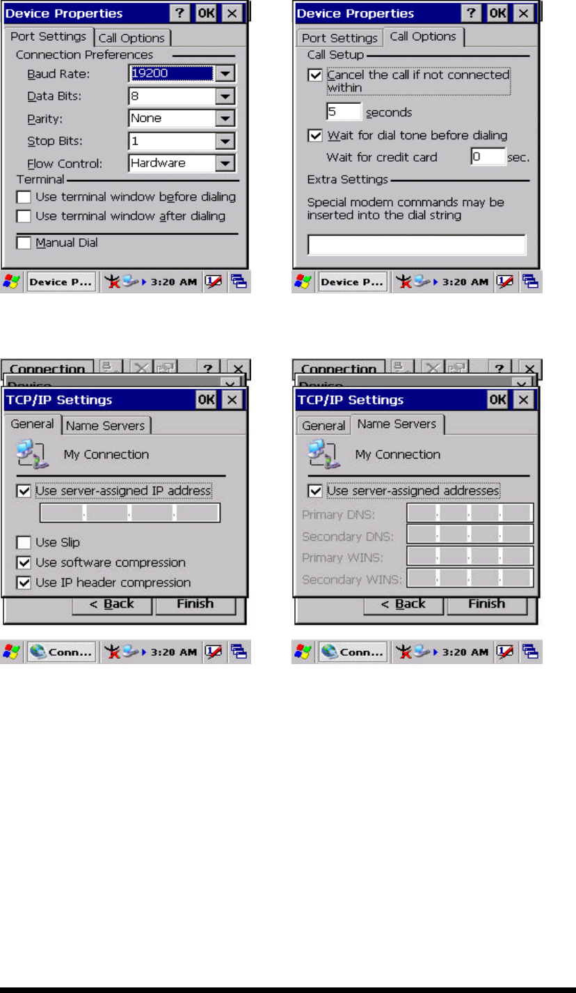
Ø Select “TCP/IP Settings”. In the “General” tab, ensure “Use
Server-assigned IP address” is selected. In the “Name
Servers” tab, ensure “Use Server-assigned addresses” is
selected, and select “OK”. If you are unable to connect with
these default settings, see your ISP or network administrator
for specific TCP/IP information.
Ø Select the “Next” button and type the telephone number.
Ø Select the “Finish” button.
The connection you just created appears as an icon in the “Network
and Dial-up Connections” folder.
ü Set up a point-to-Point Protocol(PPP) account with an ISP and
obtain the following information:
Ø Access telephone number
Ø User name
Ø Password
Once you have established an account, create a new connection on
your device. When creating this connection, you should be able to use
all of the default TCP/IP settings provided in the Make New
Connection Wizard. If you can’t connect using the default settings,
contact your ISP or access your ISP’s Web site for specific TCP/IP
information as well as primary and secondary DNS address.
ü Modify connection setting
Ø Select Start > Settings > Network and Dialup Connections
Ø Select the icon for connection settings you want to modify.
Ø Select File > Properties, or double- tap the appropriate icon.
Ø Select desired options. There may be additional settings that
depend on the connection. To modify, select the icon and
select the icon and select Advanced Settings… from the
menu.
3
-
42
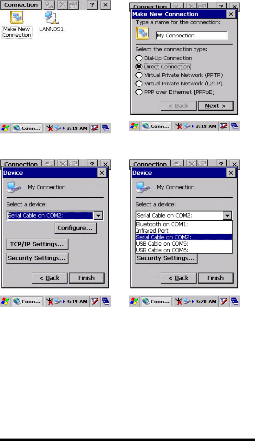
Figure 3-60 Network and Dial-up Connections
Figure 3-61 Network and Dial-up Connections
Figure 3-62 Network and Dial-up Connections
Figure 3-63 Network and Dial-up Connections
3
-
43
Figure 3-64 Network and Dial-up Connections
Figure 3-65 Network and Dial-up Connections
Figure 3-66 Network and Dial-up Connections
Figure 3-67 Network and Dial-up Connections
3
-
44
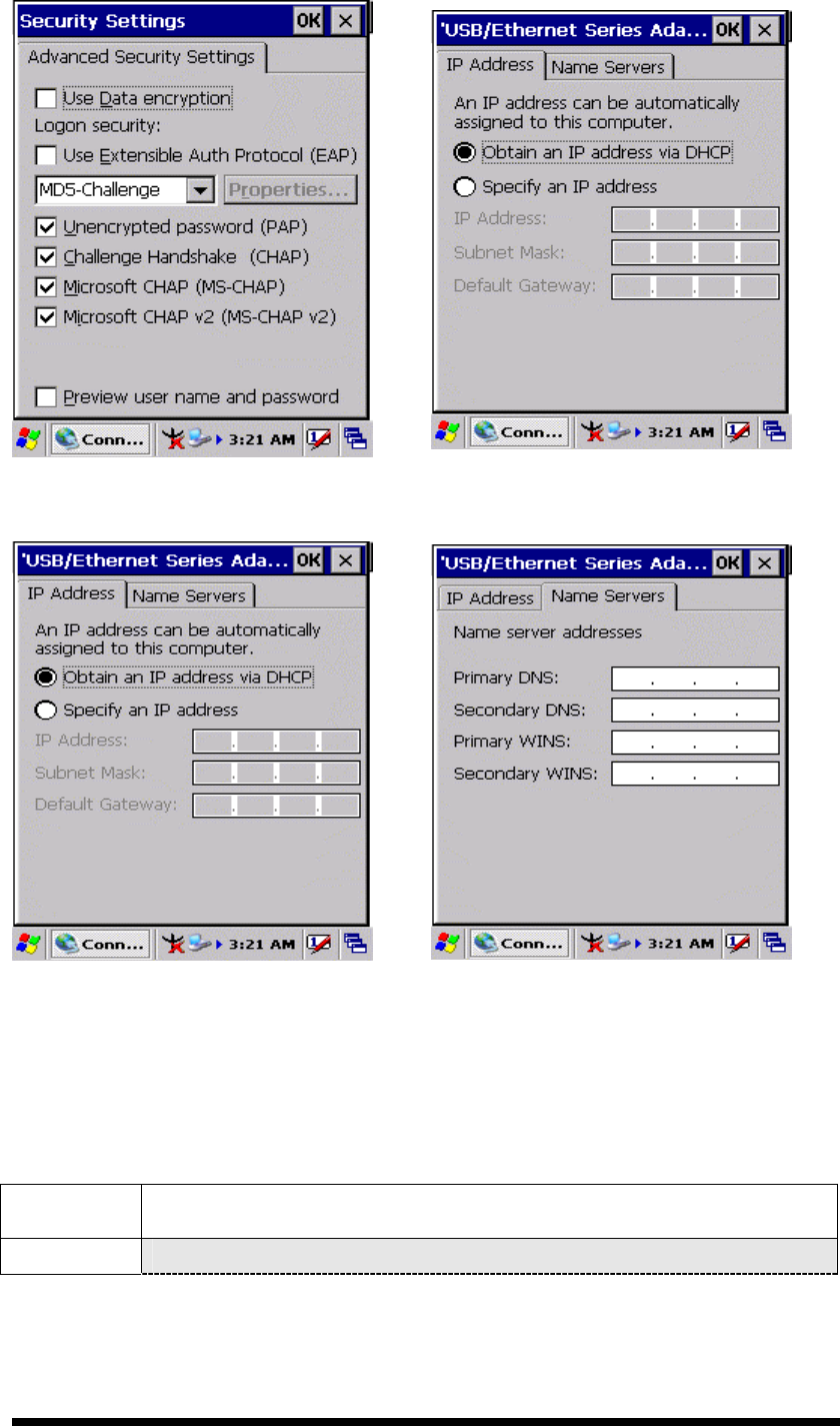
Figure 3-68 Network and Dial-up Connections
Figure 3-69 Network and Dial-up Connections
Figure 3-70 Network and Dial-up Connections
Figure 3-71 Network and Dial-up Connections
3.2.13 Owner
Table 3-32 Owner
ICON ITEM & FUNCTION
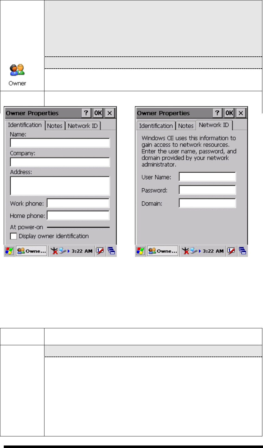
l “Identification” Tab : (Figure 3-74)
3
-
45
l “Identification” Tab : (Figure 3-74)
ü Fill in or edit the data as desired.
ü To have this information displayed when you start your device,
select “Display Owner Identification” at Power On.
ü To set up identification for remote networks, see Setting up
identification for remote networks.
l “Network ID” Tab: (Figure 3-75)
ü Enter the user name, password, and domain name you use to log
on to remote network.
Figure 3-72 Owner Properties Figure 3-73 Owner Properties
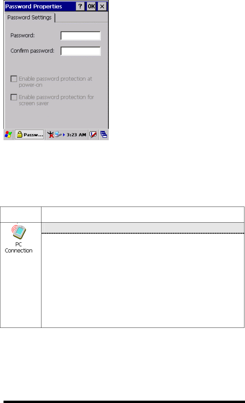
3.2.14 Password
Table 3-33 Password
ICON ITEM & FUNCTION
l “Password Setting” Tab : (Figure 3-76)
ü Enter the password
ü In the “Confirm password “box, enter the password again.
ü To require the password on startup, select “Enable password
protection at power- on“. and/or select “Enable password
protection for screen saver”
ü To exit the Password control panel, press “OK” from the
control bar, or press the <Enter> key on the keypad.
3
-
46
Figure 3-74 Password Properties
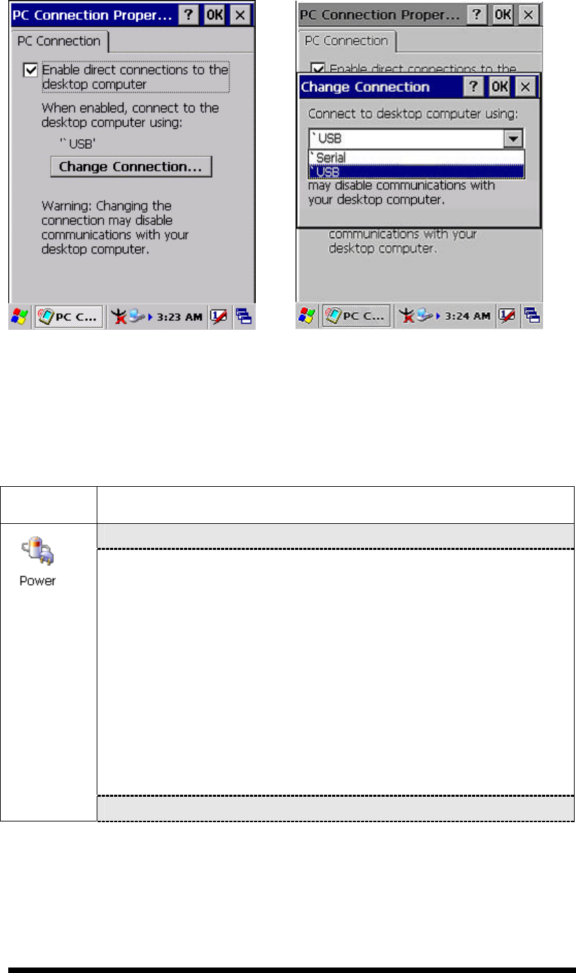
3.2.15 PC Connection
Table 3-34 PC Connection
ICON ITEM & FUNCTION
l “PC Connection” Tab : (Figure 3-77)
ü Select the first checkbox to enable direct connections to the
desktop computer. (Figure 3-77)
ü Tap the “Change Connection… ” button to modify the
connection method from USB or Serial. (Figure 3-78)
ü To exit the “Change Connection” dialog, press “OK” from the
control bar, or press the <Enter> key on the keypad.
ü To exit the “PC Connection” properties control panel, press
“OK” from the control bar, or press the <Enter> key on the
keypad.
3
-
47
Figure 3-75 PC Connection Figure 3-76 PC Connection
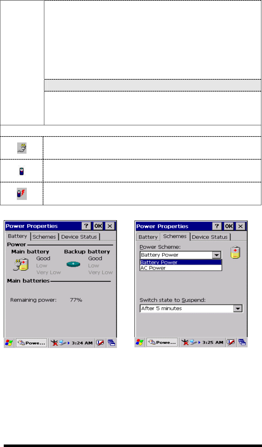
3.2.16 Power
Table 3-35 Power
ICON ITEM & FUNCTION
l “Battery” Tab : (Figure 3-79)
ü Provide change level indicators for Main battery and Backup
battery.
ü Provide remaining power capacity of main battery.
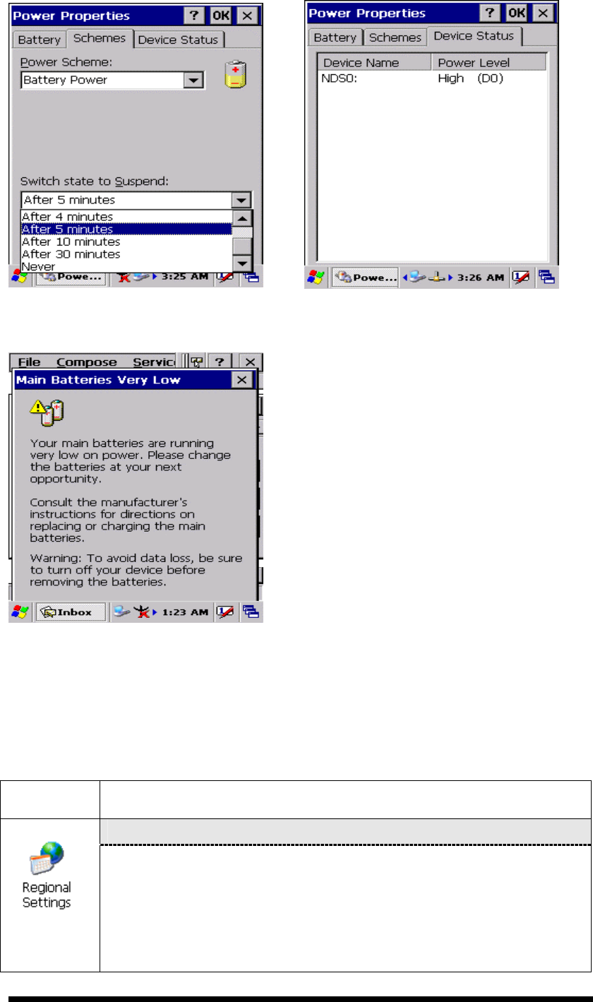
ü If a “Main Batteries very Low” warning message shows, the
remaining battery life is around 30 minutes to SC600 shuts
down. ( Figure 3-83)
ü The PDT will shutdown during the main batteries capacity is
around 0%
ü To exit Battery control panel, press “OK” from the command
bar, or press <Enter> key on keypad.
l “ Schemes” Tab: (Figure 3-80)
3
-
48
ü The Scheme Tab allows you to determine the time to switch
state to Suspend mode when using either Battery Power or AC
Power.
ü Select Battery Power or AC Power as the power scheme from
the pull-down list.( Figure 3-80)
ü Select the time to suspend mode from the pull-down list.
( Figure 3-81)
l “Device Status” Tab: ( Figure 3-82)
Provide power level of device – The power level ranges from
“ High(D0)” which means the device is at the highest power level to
“Off(D4)” which means the device is at the lowest power level.
Note:
This ICON inside the Task Bar shows that AC adapter provides power
to the PDT
The ICON inside the Task Bar shows that Main Batteries provides the
power to the PDT.
The ICON inside the Task Bar shows that AC adapter provides the
power to the PDT and is charging the main batteries..
Figure 3-77 Power Figure 3-78 Power
3
-
49
Figure 3-79 Power Figure 3-80 Power
Figure 3-81 Power
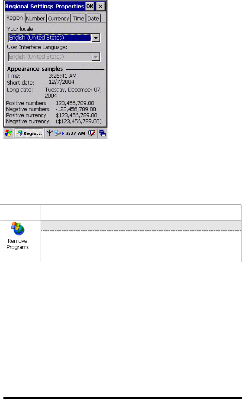
3.2.17 Regional Settings
Table 3-36 Regional Settings
ICON ITEM & FUNCTION
l “Region” Tab : (Figure 3-84)
ü Select the desired location/language.
ü Review the Appearance samples in the bottom half of the
screen.
ü Select the Tab at the top for any settings you wish to change,
Options to modify include Number, Currency, Time, and Date.
3
-
50
Figure 3-82 Regional Settings
3.2.18 Remove Programs
Table 3-37 Remove Programs
ICON ITEM & FUNCTION
l “Remove Programs” Tab :
ü Only user installed programs can be removed.
Ø Select the program you wish to remove from the list and press
“remove” button.