Welch Allyn FN802FH Propaq 802 LTRN User Manual part 4 of 10
Welch Allyn, Inc. Propaq 802 LTRN Users Manual part 4 of 10
Contents
Users Manual part 4 of 10
Directions for Use Overview of Monitor Operation 29
Assembling the Large Color Display
Refer to Figure 22, Figure 23 on page 30, or Figure 24 on page 31.
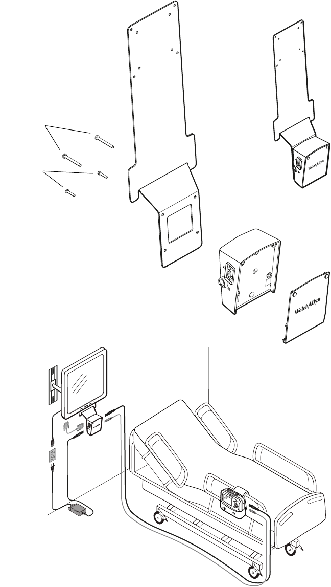
Figure 22. Mounting the Interface Box (with Face Plate) on the Large Display Mounting Bracket
60-mm screws
620-0431-00
40-mm screws
620-0432-00
Long cables between box and cradle:
008-0946-00 (USB)
008-0948-00 (Power)
30 Overview of Monitor Operation Welch Allyn Propaq LT Vital Signs Monitor
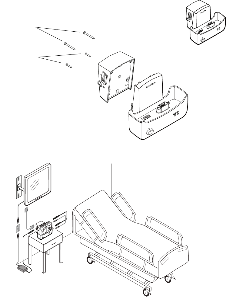
Figure 23. Mounting the Interface Box on the Cradle
40-mm screws
620-0432-00
18-mm screws
620-0433-00
Short cables between box and cradle:
008-0947-00 (USB)
008-0949-00 (AC Power)
Directions for Use Overview of Monitor Operation 31
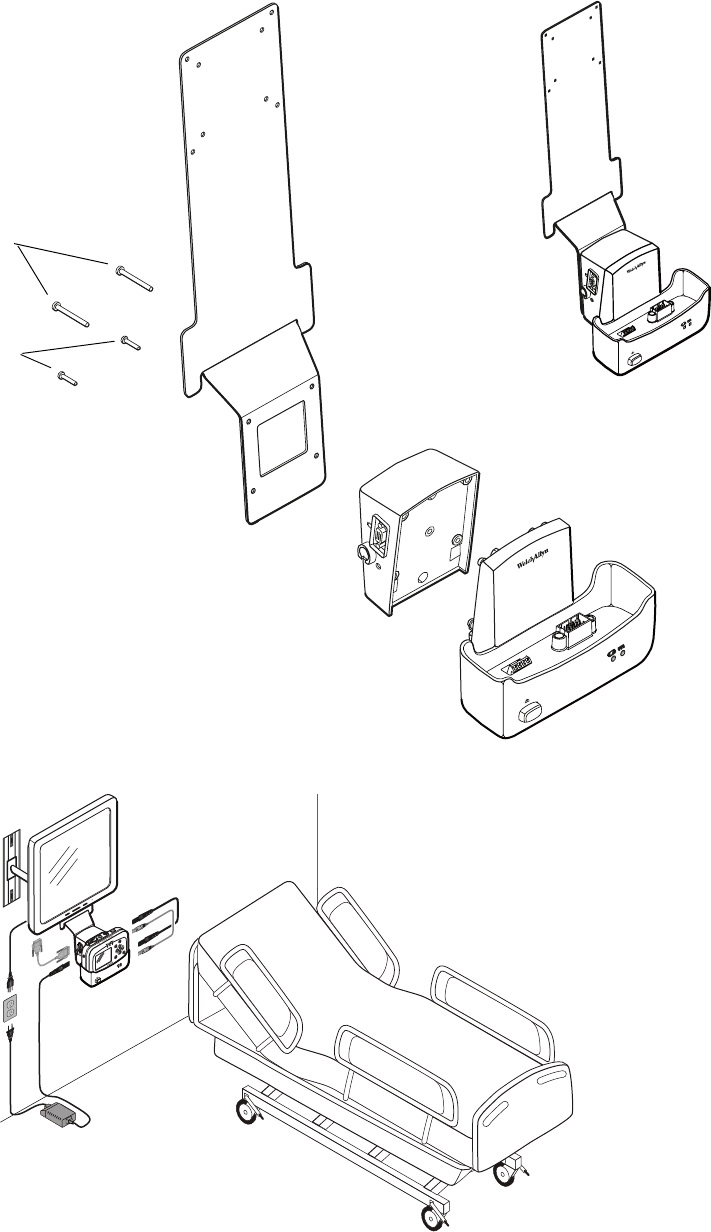
Figure 24. Mounting the Interface Box and the Cradle on the Large Display Mounting Bracket
40-mm screws
620-0432-00
60-mm screws
620-0431-00
Short cables between box and cradle:
008-0947-00 (USB)
008-0949-00 (AC Power)

32 Overview of Monitor Operation Welch Allyn Propaq LT Vital Signs Monitor
About Navigation
You navigate the monitor screens using , , and (arrow buttons), (action button),
and (display button).
Using the Arrow Buttons
Use , , and to do the following:
• Highlight an item on the display. (See “Using the Highlights” on page 33.)
• Select options from a control menu.
• Use and to select options from a pop-up menu.
• Use and to change the values of numeric parameters.
Using the Action Button
Use to do the following:
• Display the control menu for a blue-highlighted item.
• Return from a control menu to the primary display.
• Access the Setup menu when Setup is highlighted.
• Display tabular and graphical trends when Trends is highlighted.
• Display snapshots when Snapshot is highlighted.
• Turn on the display or the back light if either has been turned off by a time-out.
• Display a pop-up menu.
Using the Display Button
Use to do the following:
• Cycle through the configured display formats.
• Return from a control menu to the primary display.
• Close a pop-up menu.
Directions for Use Overview of Monitor Operation 33
Using the Highlights
Every screen contains a single element—the current context—highlighted by a blue field.
Some screens also contain elements—parameter values—highlighted by a green field.
About Blue Highlights
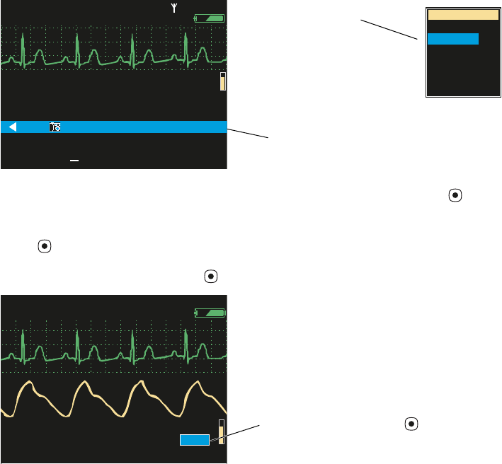
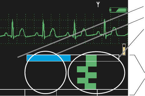
A blue highlight identifies the current context. For example, Figure 25 illustrates a
highlighted row in a trends display and a highlighted setting in the Waveform Size menu.
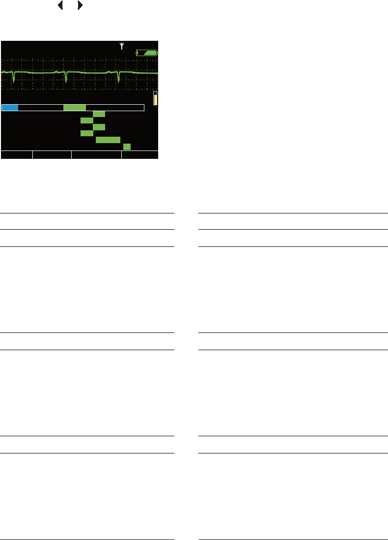
Figure 25. Examples of Highlighted Elements
In a display screen (see “About Display Formats” on page 21), pressing causes the
monitor to replace the current screen with another screen related to the current context.
For example, if SpO2 is highlighted in the Two Waveforms display (Figure 26) and you
press ...
Figure 26. Using the Action Button ( )
...the monitor presents the SpO2 control menu (Figure 27).
About Green Highlights
Green highlights identify the current values of multiple parameters within a given context.
For example, in the control menu shown in Figure 27, the current settings of the SpO2
parameters are highlighted in green.
II 1mV/cm
II 1mV/cm
%
12:41
12:41
12:40
12:40
12:39
12:39
12:38
12:38
12:37
12:37
12:38
12:38
12:36
12:36
125
125
122
122
100
100
75
75
50
50
25
25
130/65 (93)
130/65 (93)
112/87 (87)
112/87 (87)
192/110 (130)
192/110 (130)
n/a
n/a
n/a
n/a
n/a
n/a
n/a
n/a
22
22
18
18
16
16
17
17
19
19
19
19
98
98
98
98
99
99
99
99
98
98
100
100
n/a
n/a
12
12
SpO2
SpO2
SEARCH
SEARCH
Tabular
Tabular
Time
Time
80
80
140/78
140/78
HR/min
HR/min
NIBP mmHg
NIBP mmHg
Resp/min
Resp/min
n/a
n/a
HALL, ROBERT E.
HALL, ROBERT E.
3456187
3456187
12:41:32
12:41:32
Adult
Adult
Rm 239
Rm 239
Waveform Size
Waveform Size
0.2 mV/cm
0.2 mV/cm
0.5 mV/cm
0.5 mV/cm
1 mV/cm
1 mV/cm
2 mV/cm
2 mV/cm
4 mV/cm
4 mV/cm
8 mV/cm
8 mV/cm
Highlights
Drop-down menu
Vital-signs display
140/78
140/78
80
80
12
12
97
97 %
HALL, ROBERT E.
HALL, ROBERT E.
3456187
3456187
3:00:06P
3:00:06P
Adult
Adult
Rm 239
Rm 239
HR/min
HR/min
NIBP mmHg (102)
NIBP mmHg (102)
@2:47P Manual
@2:47P Manual
Resp/min
Resp/min
SpO2
SpO2
SpO2
SpO2
2x
2x
II 1mV/cm
II 1mV/cm
With SpO2 highlighted, press
(Two Waveforms display)
34 Overview of Monitor Operation Welch Allyn Propaq LT Vital Signs Monitor
Menus
Using Control Menus
Figure 27. SpO2 Control Menu (Example)
A control menu includes a topic name for the current context (for example, SpO2); a
column of parameters with one highlighted (for example, SpO2 Monitoring); and a
column of options, with one item in each set of options highlighted (for example,
Standby, On, 100, On, 90, Low).
The blue highlight indicates the parameter currently enabled for modification.
The green highlights indicate the current settings for all parameters in the menu.
At the bottom of the screen for all control menus are links to Exit, Trends, Snapshots,
and Setup.
Exit Return to the vital-signs display.
Trends View a tabular history.
Snapshots View a series of 21-second waveform snapshots of the current patient’s
vital signs.
Setup Access the setup menu. (See “To Access the Setup Menus” on page 38.)
%
HALL, ROBERT E.
HALL, ROBERT E.
3456187
3456187
3:00:06P
3:00:06P
Adult
Adult
Rm 239
Rm 239
II 1mV/cm
II 1mV/cm
Exit
Exit
Trends
Trends
Snapshots
Snapshots
Setup
Setup
SpO2 Monitoring
SpO2 Monitoring
Upper Alarm
Upper Alarm
Upper Limit
Upper Limit
Lower Alarm
Lower Alarm
Lower Limit
Lower Limit
HP/PR Tone
HP/PR Tone
SpO2
SpO2
Off
Off
Off
Off
Off
Off
Off
Off
On
On
On
On
On
On
Low
Low
Med
Med
High
High
100
100
90
90
Standby
Standby
80
80
HR/min
HR/min
140/78
140/78
NIBP mmHg (102)
NIBP mmHg (102)
Resp/min
Resp/min
SpO2
SpO2
12
12
97
97
Control menu
Control context
Parameters
Current settings

Directions for Use Overview of Monitor Operation 35
Example: Using a Control Menu
Using the example (Figure 27), you would do the following to raise the SpO2 lower alarm
limit to 95 (Step 1) and shut off the HR/PR tone (Step 2):
1. W i t h SpO2 Monitoring highlighted, scroll (using ) to highlight Lower Limit, and
press as many times as needed to raise this alarm limit to 95.
2. Scroll (using ) to HR/PR Tone, and press either or as many times as needed to
highlight Off.
3. Press or to exit the control screen and return to the vital-signs display.
About the HR/PR Control Menu
About the SpO2 Control Menu
Note If you decrease an upper alarm limit to a value almost as low as the lower limit,
the lower limit decreases so that it is always lower than the upper limit.
If you increase a lower alarm limit to a value almost as high as the upper limit, the
upper limit increases so that it is always higher than the lower limit.
Note When you change a setting (for example, by turning off an alarm limit or by
increasing or decreasing an alarm limit), the change takes effect immediately.
Note When you exit a control menu, the values displayed at the time you exit are the
values in effect for the monitor. If you change a parameter setting and then decide
before exiting the control menu to keep the previous setting values, you must
return the parameters to the original values before you exit the control menu.
Parameter Options Parameter Options
Upper Alarm Off On Lower Alarm Off On
Upper Limits Lower Limits
Adult
Pediatric
Neonate
27 - 300 beats/minute
27 - 300 beats/minute
27 - 300 beats/minute
Adult
Pediatric
Neonate
25 - 298 beats/minute
25 - 298 beats/minute
25 - 298 beats/minute
HR/PR Tone Off Low Med High Selected Source ECG SpO2
Parameter Options Parameter Options
SpO2 Monitoring Off On Standby HR/PR Tone Off Low Med High
Upper Alarm Off On Lower Alarm Off On
Upper Limit Lower Limit
Adult
Pediatric
Neonate
52% - 100%
52% - 100%
52% - 100%
Adult
Pediatric
Neonate
50% - 98%
50% - 98%
50% - 98%
36 Overview of Monitor Operation Welch Allyn Propaq LT Vital Signs Monitor
About the NIBP Control Menu
The NIBP control (Figure 28) has four submenus: Manometer, Systolic, Diastolic, and
Mean. Press or to select a submenu.
Figure 28. NIBP Control Menu
Note For manometer information, see “To Use the Digital Manometer” on page 73.
Parameter Options Parameter Options
Systolic Systolic
Upper Sys Alarm Off On Lower Sys Alarm Off On
Upper Sys Limit Lower Sys Limit
Adult
Pediatric
Neonate
32 - 260 mmHg
32 - 160 mmHg
27 - 120 mmHg
Adult
Pediatric
Neonate
30 - 258 mmHg
30 - 158 mmHg
25 - 118 mmHg
NIBP Mode Auto Manual Turbo Auto Interval (min) 123510153060
Diastolic Diastolic
Upper Dia Alarm Off On Lower Dia Alarm Off On
Upper Dia Limit Lower Dia Limit
Adult
Pediatric
Neonate
22 - 235 mmHg
17 - 130 mmHg
12 - 105 mmHg
Adult
Pediatric
Neonate
20 - 233 mmHg
15 - 128 mmHg
10 - 103 mmHg
NIBP Mode Auto Manual Turbo Auto Interval (min) 123510153060
MAP MAP
Upper MAP Alarm Off On Lower MAP Alarm Off On
Upper MAP Limit Lower MAP Limit
Adult
Pediatric
Neonate
22 - 255 mmHg
17 - 140 mmHg
12 - 110 mmHg
Adult
Pediatric
Neonate
20 - 253 mmHg
15 - 138 mmHg
10 - 108 mmHg
NIBP Mode Auto Manual Turbo Auto Interval (min) 123510153060
II 1mV/cm
II 1mV/cm
1
1
2
2
3
3
5
5
10
10
15
15
30
30
60
60
Exit
Exit
Trends
Trends
Snapshots
Snapshots
Setup
Setup
Auto
Auto
Manual
Manual
Turbo
Turbo
HR/min
HR/min
NIBP mmHg
NIBP mmHg
Resp/min
Resp/min
SpO2
SpO2
Off
Off
Off
Off
On
On
On
On
220
220
Lower Sys Limit
Lower Sys Limit
NIBP Mode
NIBP Mode
Auto Interval (min)
Auto Interval (min)
Upper Sys Alarm
Upper Sys Alarm
Upper Sys Limit
Upper Sys Limit
Lower Sys Alarm
Lower Sys Alarm
NIBP Manometer
NIBP Manometer
Systolic
Systolic
Diastolic
Diastolic
Mean
Mean
75
75
%
%
STEWART, ANN
STEWART, ANN
7762940
7762940
3:00:06P
3:00:06P
Adult
Adult
Rm 263
Rm 263
(102)
(102)
80
80
140/78
140/78
12
12
97
97

Directions for Use Overview of Monitor Operation 37
About the Resp Control Menu
Using Setup Menus
Use the Setup menus to define settings for monitor behavior.
Parameter Options Parameter Options
Resp Monitoring Off On Lower Alarm Off On
Upper Alarm Off On Lower Limit
Upper Limit Adult 2 - 148
Adult 4 - 150 Pediatric 2 - 148
Pediatric 4 - 150 Neonate 3 - 148
Neonate 5 - 150 Resp Lead Ld1 (RA-LA) Ld2 (RA-LL)
Setting Options Setting Options
Alarms NIBP
Suspend Audible Alarms Off, On (with a time value) NIBP Format SD, SD(m), sd(M)
Alarm Tone Low, Medium, High NIBP Units mmHg, kPa
ECG Smartcuf (available in 2006) Off, On
Resp Monitoring Off, On Timings
ECG Bandwidth Monitor, Extended Back Light Time Out (Min) 2, 5, 10, 15, 30, On, Off
Power Source Filter 60 Hz, 50 Hz, Off Display Time Out (Min) 2, 5, 10, 15, 30, On
Pacer Indicator Off, On Demo Mode Disabled, Low, High
38 Overview of Monitor Operation Welch Allyn Propaq LT Vital Signs Monitor
To Access the Setup Menus
From any main display screen (such as Large Numerics, Dual Waveform...):
1. Highlight , HR/PR, SpO2, NIBP, Resp, or .
2. Press .
3. Highlight Setup (at the bottom of the screen) and press .
Figure 29. Setup Menus
Note If you change parameter settings and then change the patient mode (from adult to
pediatric, for example):
•all parameters are reset to the configuration default values for the new
patient mode
•all stored patient data is lost
WARNING The Setup menus are also used to access the Service menu. Do not
enter the Service menu unless you are a qualified service person.
II 1mV/cm
II 1mV/cm
Exit
Exit
Trends
Trends
Snapshots
Snapshots
Setup
Setup
Low
Low
Med
Med
80
80
HR/min
HR/min
NIBP mmHg
NIBP mmHg
Resp/min
Resp/min
SpO2
SpO2
Off
Off
On
On
Alarm Tone
Alarm Tone
Suspend Audible Alarms
Suspend Audible Alarms
Setup
Setup
(90 sec)
(90 sec)
12
12
97
97 %
ID: 01018VDO9PBH
ID: 01018VDO9PBH
3:00:06P
3:00:06P
Adult
Adult
Rm 239
Rm 239
Alarms
Alarms
ECG
ECG
NIBP
NIBP
Timings
Timings
High
High
Service
Service
SIMULATION
SIMULATION
Setup
Directions for Use Overview of Monitor Operation 39
About Monitor Information Screens
Both the start-up information screen and the monitoring information screen provide
information about the monitor.
To View the Start Up Information Screen
From the power-on screen (Figure 7 on page 14), highlight Info.
Figure 30. Start-Up Information
The start-up information screen provides the following:
• Monitor type (LTRN=wireless, LT0N=standalone), serial #, and software version #
(V X.XX.XX)
• Medical facility name and department
• Configuration file name
• Contact person’s name and telephone number
• Current patient mode (Adult, Pediatric, Neonate)
• Number of data snapshots saved (0 - 20)
• Network communications status (Enabled, Disabled)
To exit the start-up information screen, do one of the following:
• Highlight Continue Patient or Start New Patient to start monitoring.
• Highlight Demo to enter Demo mode.
• Press to turn off the monitor.
Welch Allyn Propaq 802LTRN
Welch Allyn Propaq 802LTRN
Serial# F82C0DD5 V1.00.00
Serial# F82C0DD5 V1.00.00
Portland Westside
Portland Westside
Emergency Department
Emergency Department
PtldWstsdED10Jun05.mnt
PtldWstsdED10Jun05.mnt
Ann Jones, MD
Ann Jones, MD
503-530-0101 x9999
503-530-0101 x9999
Patient Mode
Patient Mode
Wireless Communications
Wireless Communications
Start New Patient
Start New Patient
Info
Info
Demo
Demo
Adult
Adult
Snapshots
Snapshots
none saved
none saved
Enabled
Enabled
Welch Allyn Propaq 802LT0N
Welch Allyn Propaq 802LT0N
Serial# AB72383-1 V1.00.00
Serial# AB72383-1 V1.00.00
Portland Westside
Portland Westside
Emergency Department
Emergency Department
PtldWstsdED10Jun05.mnt
PtldWstsdED10Jun05.mnt
Ann Jones, MD
Ann Jones, MD
503-530-0101 x9999
503-530-0101 x9999
Patient Mode
Patient Mode
Wireless Communications
Wireless Communications
Start New Patient
Start New Patient
Info
Info
Demo
Demo
Adult
Adult
Snapshots
Snapshots
14 of 20 saved
14 of 20 saved
Disabled
Disabled
Continue Patient
Continue Patient
40 Overview of Monitor Operation Welch Allyn Propaq LT Vital Signs Monitor
To View the Monitoring Information Screen
Highlight (in the upper right corner of the vital-signs display) and press .
Figure 31. Monitoring Information
The monitoring information screen provides the following information:
• Continuous numeric and waveform display of patient vital signs
• Medical facility name and unit
• Configuration file name.
• Contact person’s name and telephone number
To exit the monitoring information screen, do one of the following:
• To return to the primary display, press , or highlight Exit and press .
• To see a tabular display of vital signs, highlight Tre n d s and press .
• To view saved snapshots of vital signs, highlight Snapshots and press .
• To view the Setup menu, highlight Setup and press .
• To turn off the monitor, press .
II 1mV/cm
II 1mV/cm
Exit
Exit
Trends
Trends
Snapshots
Snapshots
Setup
Setup
80
80
HR/min
HR/min
(100)
(100)
NIBP mmHg (148-86)
NIBP mmHg (148-86)
Resp/min
Resp/min
SpO2
SpO2
503-530-0101 x9999
503-530-0101 x9999
Emergency Department
Emergency Department
PtldWstsdED10Jun05.mnt
PtldWstsdED10Jun05.mnt
Ann Jones, MD
Ann Jones, MD
Portland Westside
Portland Westside
12
12
97
97 %
HALL, ROBERT E.
HALL, ROBERT E.
3456187
3456187
12:41:32
12:41:32
Adult
Adult
Rm 239
Rm 239

Directions for Use Overview of Monitor Operation 41
Using Demo Mode
In Demo mode, the monitor displays simulated patient data for all vital signs. You can use
Demo mode to practice taking vital-signs measurements, modifying alarm limits and
other settings, cycling through display formats, and responding to alarm conditions.
To start Demo mode, all of the following must be true:
• The power-on screen is displayed.
• The monitor is not in NIBP Auto mode.
• Patient data was deleted when the monitor was last shut down; that is, the
monitor contains no stored patient data.
•The SpO
2 and ECG cables are not connected to the monitor.
To Enter Demo Mode Low
1. Verify that the SpO2 and ECG cables are not connected to the monitor.
2. Cycle the monitor off (deleting any saved data) and then on again.
3. When the main screen appears, highlight Demo (Figure 32) and press .
Figure 32. Power-On Screen: Demo Highlighted
Demo mode is indicated by the message ‘SIMULATION’ in the upper left corner of
the screen (Figure 33). If the monitor is connected to Acuity, ‘SIMULATION’ also
appears on the Acuity display.
Note If you enter Demo mode with an SpO2 or ECG cable connected, the monitor
enters Demo mode for only a second or two before shutting down and powering
up in monitor mode.
If you are in Demo mode and you connect an SpO2 or ECG cable or select NIBP
auto mode, the monitor shuts down and powers up to the start-up screen.
Select ( ) to enter Demo Mode
Select ( ) to enter Demo Mode
No data saved.
No data saved.
Start New Patient
Start New Patient
Info
Info
Demo
Demo
(unplug patient cables)
(unplug patient cables)
42 Overview of Monitor Operation Welch Allyn Propaq LT Vital Signs Monitor
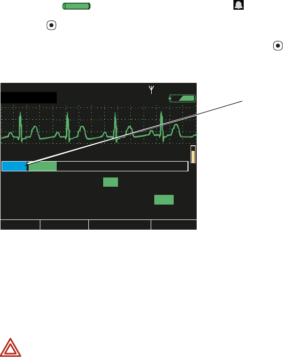
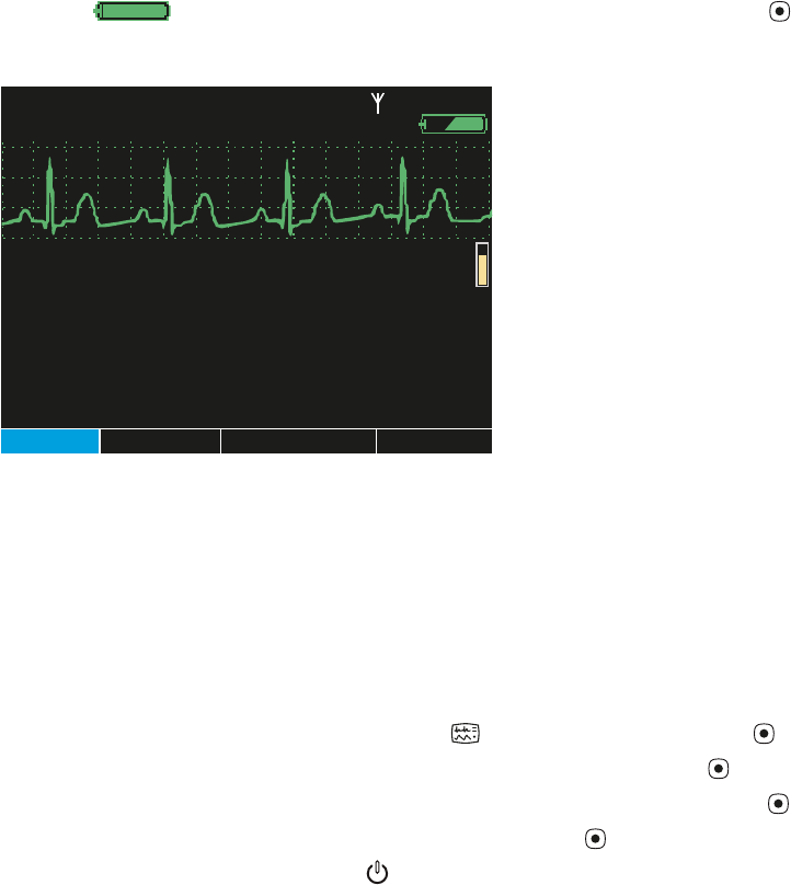
Figure 33. Demo Mode: Initial Display
When you enter Demo mode, the monitor is in ‘Demo Mode Low’. The simulated vital
signs of the patient are steady and do not cause any alarms at the default alarm limit
settings. You can explore the monitor displays and menus, and you can change the same
settings and values in Demo mode that you can change in normal mode.
In Demo Mode Low, if you adjust the alarm limits to put the simulated patient’s vital signs
out of limits, the monitor simulates an alarm condition. Another way to simulate an alarm
condition is to switch the monitor to Demo Mode High, which uses higher numeric
values.
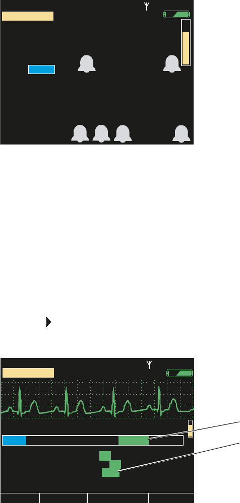
To Switch to Demo Mode High
1. Access the Setup menu. (“To Access the Setup Menus” on page 38.)
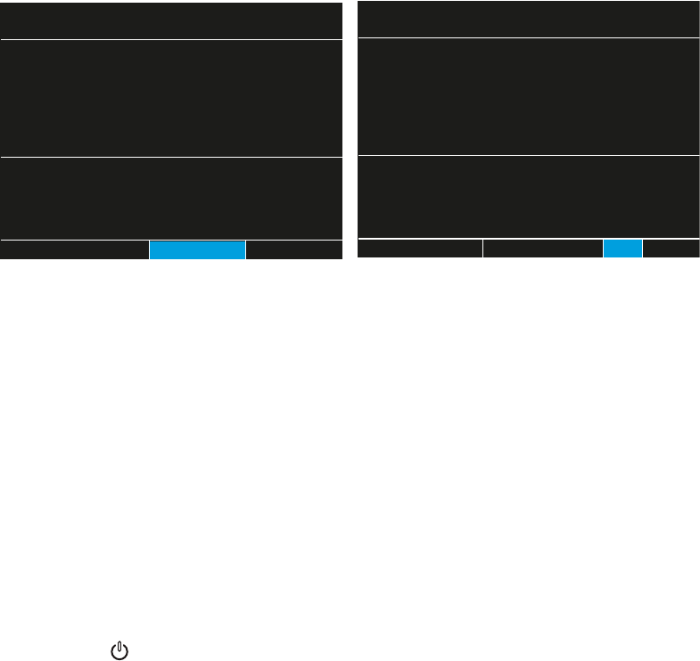
2. Press to highlight Timings (Figure 34).
Figure 34. Setup: Timings
80
80
97
97
12
12
ID: 01018VDO9PBH
ID: 01018VDO9PBH
3:00:06P
3:00:06P
Adult
Adult
Rm 239
Rm 239
NIBP mmHg
NIBP mmHg
Resp/min
Resp/min
HR/min
HR/min
SpO2
SpO2
%
SIMULATION
SIMULATION
S D M
10
10
15
15
30
30
On
On
Off
Off
II 1mV/cm
II 1mV/cm
Exit
Exit
Trends
Trends
Snapshots
Snapshots
Setup
Setup
80
80
HR/min
HR/min
NIBP mmHg
NIBP mmHg
Resp/min
Resp/min
SpO2
SpO2
Demo Mode
Demo Mode
Backlight Timeout (min)
Backlight Timeout (min)
Setup
Setup
12
12
97
97 %
ID: 01018VDO9PBH
ID: 01018VDO9PBH
3:00:06P
3:00:06P
Adult
Adult
Rm 239
Rm 239
Alarms
Alarms
ECG
ECG
NIBP
NIBP
Timings
Timings
Service
Service
Display Timeout (min)
Display Timeout (min) 2
Low
Low
5
10
10
15
15
30
30
On
On
Off
Off25
SIMULATION
SIMULATION
High
High
Timings
Default Demo mode (Low)
Directions for Use Overview of Monitor Operation 43
The Timings menu specifies the Demo mode—Demo Mode Low, which simulates
normal vital signs, and Demo Mode High, which simulates a higher heart rate (HR),
higher respiration rate (Resp), and lower oxygen saturation (SpO2).
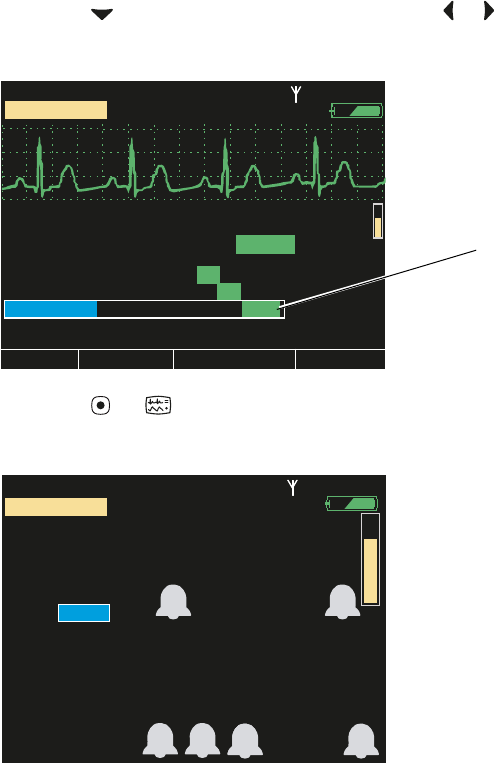
3. Press to highlight Demo Mode, and press or to highlight High (Figure 35).
Figure 35. Setup: Timings: Demo Mode High
4. Press or to return to the main display (Figure 36).
Figure 36. Demo Mode High: Initial Display
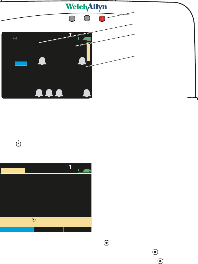
The monitor generates an alarm within seconds of reading this new set of simulated
vital signs. The red alarm indicator (Figure 37) illuminates and flashes, the numerics
for all violating vital signs—HR, SpO2, and Resp—turn red and flash, and the highlight
moves to the most recent alarming numeric.
10
10
15
15
30
30
On
On
Off
Off
II 1mV/cm
II 1mV/cm
Exit
Exit
Trends
Trends
Snapshots
Snapshots
Setup
Setup
80
80
HR/min
HR/min
NIBP mmHg
NIBP mmHg
Resp/min
Resp/min
SpO2
SpO2
Demo Mode
Demo Mode
Backlight Timeout (min)
Backlight Timeout (min)
Setup
Setup
12
12
97
97 %
ID: 01018VDO9PBH
ID: 01018VDO9PBH
3:00:06P
3:00:06P
Adult
Adult
Rm 239
Rm 239
Alarms
Alarms
ECG
ECG
NIBP
NIBP
Timings
Timings
Service
Service
Display Timeout (min)
Display Timeout (min) 2
Low
Low
5
10
10
15
15
30
30
On
On
Off
Off25
SIMULATION
SIMULATION
High
High
Demo Mode: High
80
80
97
97
12
12
ID: 01018VDO9PBH
ID: 01018VDO9PBH
3:00:06P
3:00:06P
Adult
Adult
Rm 239
Rm 239
NIBP mmHg
NIBP mmHg
Resp/min
Resp/min
HR/min
HR/min
SpO2
SpO2
%
SIMULATION
SIMULATION
S D M
44 Overview of Monitor Operation Welch Allyn Propaq LT Vital Signs Monitor
Figure 37. Demo Mode High: Simulated Alarm Condition
With the monitor simulating an alarm, you can practice responding to alarms. (See
“Responding to an Alarm” on page 90.)
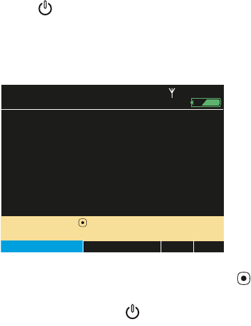
To Exit Demo Mode
Press . The Demo Mode Power Off screen appears (Figure 38).
Figure 38. Demo Mode Power Off
• To shut down the monitor, press . (No data can be saved from Demo mode.)
• To resume Demo mode, highlight Cancel and press .
• To access the Setup menu, highlight Setup and press .
1
40
40/
78
78
80
80
12
12
97
97%
HALL, ROBERT E.
HALL, ROBERT E.
3456187
3456187
3:00:06P
3:00:06P
Adult,
Adult,
Rm 239
Rm 239
HR/min
HR/min
NIBP mmHg (102)
NIBP mmHg (102)
@2:47P Manual
@2:47P Manual
Resp/min
Resp/min
SpO2
SpO2
SpO2
SpO2
2x
2x
II 1mV/cm
II 1mV/cm
125
125
88
88
31
31
ID: 01018VDO9PBH
ID: 01018VDO9PBH
3:00:06P
3:00:06P
Adult
Adult
Rm 239
Rm 239
NIBP mmHg
NIBP mmHg
Resp/min
Resp/min
HR/min
HR/min
SpO2
SpO2
%
Select ( ) for controls
Select ( ) for controls
S D M
HR limit violation (red)
SpO2 limit violation (red)
Resp limit violation (red)
Flashing red: patient alarm
Select ( ) to delete patient data
Select ( ) to delete patient data
You have pressed the Power Off button.
You have pressed the Power Off button.
Delete & Shut Down
Delete & Shut Down
Cancel
Cancel
Setup
Setup
and shut down.
and shut down.
ID: 01018VDO9PBH
ID: 01018VDO9PBH
15:01:24
15:01:24
Adult
Adult
Rm 239
Rm 239
SIMULATION
SIMULATION
Directions for Use Overview of Monitor Operation 45
Power Saving
To maximize battery life, the monitor display shuts off when the following conditions are
all true:
• No button press for a period of n seconds. (n is configurable.) See “Timing Out
the Display and the Back Light” on page 23.
• No active alarms or alerts
• No Acuity Message window
• No Patient ID entry window
Turning Off the Monitor
To Tu rn O ff t h e M o n i t o r
Press .
The Power Off screen appears (Figure 39):
Figure 39. Power Off Screen
Highlight the desired action and press .
Communicating with an Acuity Central Station
See “Monitoring in Communication with Acuity” on page 77, and see Acuity Directions
for Use.
About Error Detection
The monitor can detect conditions that prevent it from operating properly. If this occurs, it
displays an error message and number. Follow the directions displayed on the screen.
Note If you press to power down before leaving the power-on screen (Figure 7 on
page 14), the monitor shuts down without presenting the screen shown above.
Select ( ) to delete patient data
Select ( ) to delete patient data
You have pressed the Power Off button.
You have pressed the Power Off button.
Delete & Shut Down
Delete & Shut Down
Cancel
Cancel
Setup
Setup
and shut down.
and shut down.
15:01:24
15:01:24
Adult
Adult
Rm 239
Rm 239
There is patient data stored for
There is patient data stored for
Hall, Robert E. ID: 3456187
Hall, Robert E. ID: 3456187
Save & Shut Down
Save & Shut Down
HALL, ROBERT E.
HALL, ROBERT E.
3456187
3456187
46 Overview of Monitor Operation Welch Allyn Propaq LT Vital Signs Monitor
Transporting the Monitor with the Patient
An ambulatory patient can wear or carry the monitor using the Wearable Strap or the
Patient Carry Strap (optional accessories). Medical personnel can use the Transport
Stretcher Carry Strap to keep the monitor with a patient during stretcher transport.
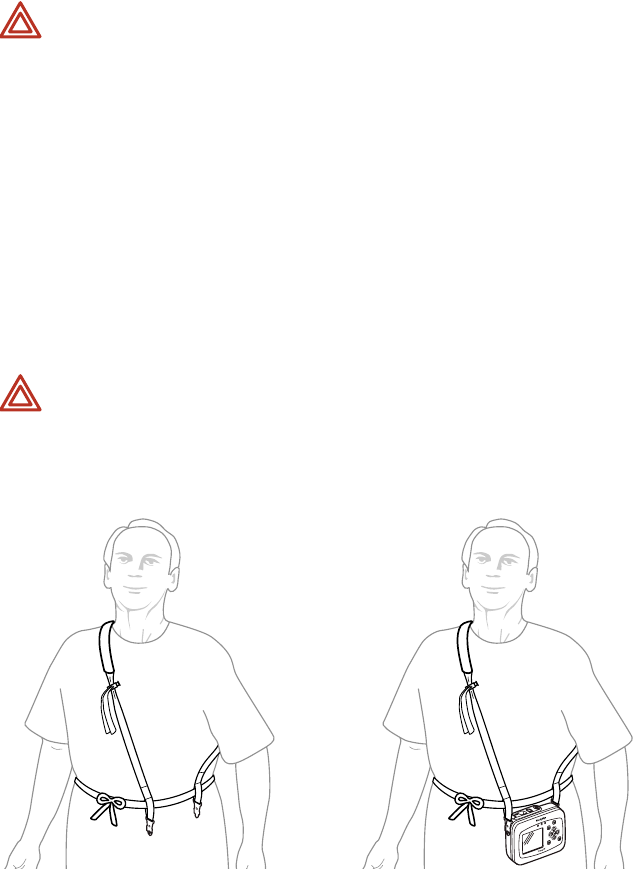
To Attach the Wearable Strap
Figure 40. Patient-Wearable Strap
1. Place the wearable strap on the sitting or standing patient and adjust all components
for a comfortable, secure fit (Figure 40 left).
2. Connect the wearable strap securely to the monitor strap mounts (Figure 40 right).
3. Carefully arrange the strap and the monitor on the patient to avoid bruising or other
skin injuries.
WARNING When the patient is wearing or carrying the monitor, carefully route
any patient cabling to reduce the possibility of patient entanglement or
strangulation. Use the supplied garment clips to secure the cable properly.
WARNING When positioning straps on the patient, make sure the straps do not
entangle the patient’s neck or cause choking.
WARNING Make sure the straps do not restrict the movement of the patient’s
limbs or create a hazard for the patient when the patient is walking or moving.
WARNING Never use a strap to carry or pick up both the monitor and the cradle.
The straps are not intended to support, and cannot support, the combined weight
of the monitor and the cradle.
WARNING Do not put the wearable strap on the patient while the patient is in
bed. The intended use of the wearable strap is to keep the monitor—without the
cradle—with the patient when the patient is ambulatory.

Directions for Use Overview of Monitor Operation 47
To Use the Patient Carry Strap (Figure 41)
1. Remove the monitor from the cradle.
2. Detach any monitor cables from such accessories as an IV pole.
3. Verify that all cables are disentangled from the bed and any bedside tables.
4. Connect the ends of the carry strap to the strap mounts on the monitor.
Figure 41. Patient Carry Strap
To Use the Transport Stretcher Carry Strap (Figure 42)
1. With the monitor facing away from the stretcher and the patient, attach one end of
the strap to a monitor strap mount.
2. Run the monitor strap under the stretcher restraint straps, near the patient’s waist.
3. Attach the other end of the strap to the other strap mount.
Figure 42. Monitor Secured to the Patient During Stretcher Transport
4. Before transporting the patient, verify that all monitor cables are clear.
WARNING Do not use the patient carry strap to lift or carry both the monitor and
the cradle. The patient carry strap is not intended to support (and cannot support)
the weight of both the monitor and the cradle. Attempting to carry both the
monitor and the cradle with a patient carry strap could lead to patient injury and to
damage to the monitor and the cradle.
48 Overview of Monitor Operation Welch Allyn Propaq LT Vital Signs Monitor