Welch Allyn FN802FH Propaq 802 LTRN User Manual part 7 of 10
Welch Allyn, Inc. Propaq 802 LTRN Users Manual part 7 of 10
Contents
Users Manual part 7 of 10

5
85
Alarms and Alerts
Overview . . . . . . . . . . . . . . . . . . . . . . . . . . . . . . . . . . . . . . . . . . . . . . . . . . . . . . .85
Responding to an Alarm . . . . . . . . . . . . . . . . . . . . . . . . . . . . . . . . . . . . . . . . . . .90
Silencing an Alarm or Alert Tone . . . . . . . . . . . . . . . . . . . . . . . . . . . . . . . . . . . . .86
Suspending the Alarm Tone. . . . . . . . . . . . . . . . . . . . . . . . . . . . . . . . . . . . . . . . .87
Customizing Alarm Limits . . . . . . . . . . . . . . . . . . . . . . . . . . . . . . . . . . . . . . . . . .89
About ParamSet. . . . . . . . . . . . . . . . . . . . . . . . . . . . . . . . . . . . . . . . . . . . . . . . . .90
Responding to an Alert . . . . . . . . . . . . . . . . . . . . . . . . . . . . . . . . . . . . . . . . . . . .90
About Battery Charge Status . . . . . . . . . . . . . . . . . . . . . . . . . . . . . . . . . . . . . . . .91
Alert Messages and Status Messages . . . . . . . . . . . . . . . . . . . . . . . . . . . . . . . .92
Overview
An Alarm warns of a patient condition, such as a vital-sign reading that is outside of
acceptable limits. When an alarm occurs, the red light on the monitor flashes and the
numerics of the violating alarm limits on the display turn red. If tones are not suspended,
the alarm tone sounds.
An Alert warns of an equipment condition, such as a low battery or a detached lead.
When an alert occurs, the yellow light on the monitor flashes and a message describing
the error condition appears on the display. If tones are not suspended, the alert tone
sounds.
Alarms have priority over alerts. If an alarm and an alert are detected simultaneously, the
monitor notifies you of the alarm. It then notifies you of the alert only if the alert condition
still exists after the alarm condition is removed.
86 Alarms and Alerts Welch Allyn Propaq LT Vital Signs Monitor
Silencing an Alarm or Alert Tone
A tone sounds whenever the monitor detects an alarm or alert condition.
To Silence the Currently Sounding Tone for 90 Seconds
1. P r e s s .
• The red light (alarm) or the yellow light (alert) flashes.
• After 90 seconds, if the condition is not corrected, the tone starts again.
• If the condition is corrected within 90 seconds of silencing the tone, the monitor
resets the tones for the next alarm or alert.
If a new alarm or alert condition occurs while an earlier alarm or alert is silenced, the
tone sounds again.
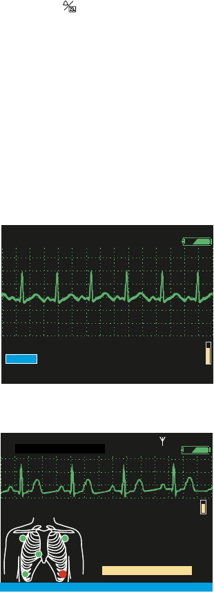
Figure 84. Sample Alarm Screen
Figure 85. Sample Alert Screen
2. Check the patient and provide appropriate care.
Note Silencing the tone does not affect the other alarm or alert indicators.
%
140/78
140/78
125
125
31
31
88
88
HALL, ROBERT E.
HALL, ROBERT E.
3456187
3456187
3:00:06P
3:00:06P
Adult
Adult
Rm 239
Rm 239
HR/min
HR/min
NIBP mmHg (102)
NIBP mmHg (102)
@2:47P Manual
@2:47P Manual
Resp/min
Resp/min
SpO2
SpO2
II 1mV/cm
II 1mV/cm
X
Resp/min
Resp/min
SpO2
SpO2
I 1mV/cm
I 1mV/cm
HALL, ROBERT E.
HALL, ROBERT E.
3456187
3456187
12:41:32
12:41:32
Adult
Adult
Rm 239
Rm 239
Audible Alarms Silenced
Audible Alarms Silenced
80
80
140/78
140/78
12
12
97
97 %
HR/min
HR/min
NIBP mmHg (102)
NIBP mmHg (102)
@2:47P Manual
@2:47P Manual
EQUIPMENT ALERT
EQUIPMENT ALERT
ECG Fault
ECG Fault
LL Lead Failed
LL Lead Failed
ACKNOWLEDGE
ACKNOWLEDGE

Directions for Use Alarms and Alerts 87
3. Press to silence the audible tone for 90 seconds at the monitor and at Acuity.
• Silencing the audible tone does not remove visual alarm or alert indications.
• Silencing the audible tone causes an alarm or alert suspend at Acuity.
• When the alarm or alert condition is corrected, all alarm or alert indicators cease
and all alarms are immediately rearmed.
4. After caring for the patient, verify that alarm limits are enabled and correctly set.
Suspending the Alarm Tone
If this feature is enabled in the monitor configuration (See “Monitor Configuration” on
page 111), you can suspend all alarm tones for all parameters—preventing the alarm tone
from sounding if an alarm condition occurs—while monitoring a patient. If an alarm
condition occurs while the alarm tones ars suspended, the monitor presents visual alarm
indicators but does not sound the tone.
In the monitor configuration, the alarm tone suspension period can be set to Disabled, to
Always On, or to a period: 90 sec or 2, 3, 4, 5, 10, 15, 30, or 60 minutes.
• If it is configured to Disabled, you cannot suspend the alarm tone at the monitor.
• If it is configured to Always On and you set Suspend Audible Alarms to On,
then the alarm tone remains suspended until:
•you set Suspend Audible Alarms to Off or
• monitor power is turned off and then turned on again or
• the monitor is reconfigured
To Suspend the Alarm Tone
1. Access the Setup menu. (See “To Access the Setup Menus” on page 38.)
2. Highlight Suspend Audible Alarms (Figure 86).
The configured suspension period—90 seconds in this example—is displayed to the
right of the line.
WARNING If you turn off or modify any alarm limits while responding to an
alarm, restore the appropriate alarm limits before you resume monitoring.
Note The factory default suspension period is 4 minutes.
Note Suspend Audible Alarms does not affect the behavior of the alarm silence/
reset feature ( ). Pressing always either silences a sounding alarm tone for 90
seconds or resets the audible alarm if it was already silenced.
88 Alarms and Alerts Welch Allyn Propaq LT Vital Signs Monitor
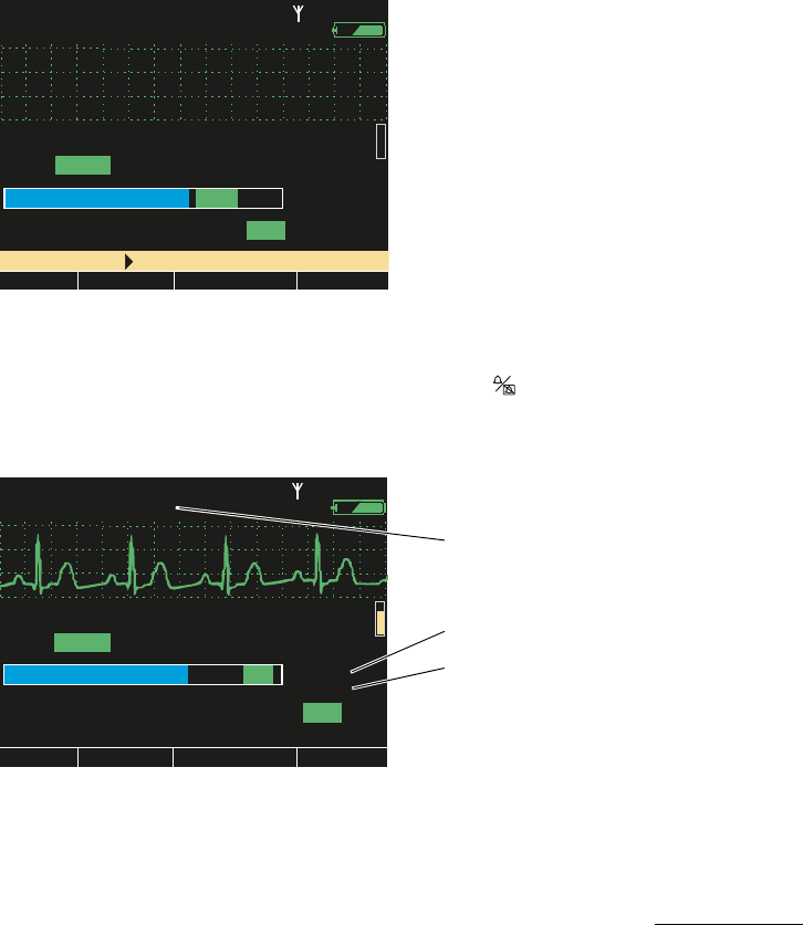
Figure 86. Suspend Audible Alarms: Off
3. Highlight On (Figure 87).
Figure 87. Suspend Audible Alarms: On
• The alarm tone is suspended immediately.
If an alarm condition occurs during the suspension period, the alarm tone does
not sound.
• A count-down timer appears below the line to indicate the time remaining in the
suspension period.
• ‘Audio alarms suspended’ appears in yellow in the upper left corner of the screen.
• When the suspension period elapses, the alarm tone is again enabled.
Note If audible alarms are suspended, pressing cancels the suspension.
II 1mV/cm
II 1mV/cm
Exit
Exit
Trends
Trends
Sna
p
shots
Snapshots
Setu
pSetup
Low
Low
Med
Med
HR/min
HR/min
NIBP mmHg
NIBP mmHg
Resp/min
Resp/min
SpO2
SpO2
Off
Off
On
On
Alarm Tone
Alarm Tone
Suspend Audible Alarms
Suspend Audible Alarms
Setup
Setup
(90 sec)
(90 sec)
%
3:00:06P
3:00:06P
Adult
Adult
Rm 239
Rm 239
Alarms
Alarms
ECG
ECG
NIBP
NIBP
Timings
Timings
High
High
Service
Service
HALL, ROBERT E.
HALL, ROBERT E.
3456187
3456187
Right ( ) to suspend audible alarms.
Right ( ) to suspend audible alarms.
II 1mV/cm
II 1mV/cm
Exit
Exit
Trends
Trends
Snapshots
Snapshots
Setup
Setup
Low
Low
Med
Med
80
80
HR/min
HR/min
NIBP mmHg
NIBP mmHg
Resp/min
Resp/min
SpO2
SpO2
Off
Off
On
On
Alarm Tone
Alarm Tone
Suspend Audible Alarms
Suspend Audible Alarms
Setup:
Setup:
(90 sec)
(90 sec)
12
12
97
97
%
8765432
8765432
3:00:06P
3:00:06P
Adult
Adult
Rm 239
Rm 239
Alarms
Alarms
ECG
ECG
NIBP
NIBP
Timings
Timings
High
High
Service
Service
0:01:30 remaining
0:01:30 remaining
Audio alarms suspended
Audio alarms suspended
ID: 01018VDO9PBH
ID: 01018VDO9PBH
‘Tone suspended’ indicator
Suspension time remaining
Configured suspension period

Directions for Use Alarms and Alerts 89
Customizing Alarm Limits
At the Monitor
Typically, each institution defines the patient alarm limits for adult, pediatric, and neonatal
patients, and then configures the monitor with those alarm limits before putting the
monitor into service.
Alarm limits can be temporarily customized for an individual patient while the monitor is in
use. Later, when the monitor is turned off in preparation for monitoring another patient,
the temporary alarm limits are lost and the configured alarm limits are restored.
To Temporarily Customize Alarm Limits for the Current Patient
1. Highlight the vital sign for which you want to set custom limits.
2. Press .
3. Highlight the limit you want to change.
4. Set a new alarm limit.
Figure 88. Customizing Alarm Limits for the Current Patient
5. Press .
At Acuity
For a wireless monitor, patient alarm limits can also be customized from Acuity. (See the
user manual for any Acuity Central Monitoring Station.)
II 1mV/cm
II 1mV/cm
1
1
2
2
3
3
5
5
10
10
15
15
30
30
60
60
Exit
Exit
Trends
Trends
Snapshots
Snapshots
Setup
Setup
Auto
Auto
Manual
Manual
Turbo
Turbo
HR/min
HR/min
NIBP mmHg
NIBP mmHg
Resp/min
Resp/min
SpO2
SpO2
Off
Off
Off
Off
On
On
On
On
220
220
Lower Sys Limit
Lower Sys Limit
NIBP Mode
NIBP Mode
Auto Interval (min)
Auto Interval (min)
Upper Sys Alarm
Upper Sys Alarm
Upper Sys Limit
Upper Sys Limit
Lower Sys Alarm
Lower Sys Alarm
NIBP Manometer
NIBP Manometer
Systolic
Systolic
Diastolic
Diastolic
Mean
Mean
75
75
%
%
STEWART, ANN
STEWART, ANN
7762940
7762940
3:00:06P
3:00:06P
Adult
Adult
Rm 263
Rm 263
125
125
140/78
140/78
31
31
88
88
(102)
(102)
II 1mV/cm
II 1mV/cm
1
1
2
2
3
3
5
5
10
10
15
15
30
30
60
60
Exit
Exit
Trends
Trends
Snapshots
Snapshots
Setup
Setup
Auto
Auto
Manual
Manual
Turbo
Turbo
HR/min
HR/min
NIBP mmHg
NIBP mmHg
Resp/min
Resp/min
SpO2
SpO2
Off
Off
Off
Off
On
On
On
On
210
210
Lower Sys Limit
Lower Sys Limit
NIBP Mode
NIBP Mode
Auto Interval (min)
Auto Interval (min)
Upper Sys Alarm
Upper Sys Alarm
Upper Sys Limit
Upper Sys Limit
Lower Sys Alarm
Lower Sys Alarm
NIBP Manometer
NIBP Manometer
Systolic
Systolic
Diastolic
Diastolic
Mean
Mean
65
65
%
%
STEWART, ANN
STEWART, ANN
7762940
7762940
3:00:06P
3:00:06P
Adult
Adult
Rm 263
Rm 263
(102)
(102)
125
125
140/78
140/78
31
31
88
88

90 Alarms and Alerts Welch Allyn Propaq LT Vital Signs Monitor
About ParamSet
Using ParamSet, you can quickly widen the alarm limits by a configured percentage
(relative to the patient’s alarming reading) for any vital sign.
For information about ParamSet, see “ParamSet” on page 154.
Responding to an Alarm
An alarm condition is indicated on the monitor in the following ways:
• The RED indicator (rightmost of three) above the display screen flashes.
• The numerics for the vital sign in alarm are displayed in RED.
• The alarm-tone sequence sounds repeatedly—3 short tones, a short pause, 2 short
tones, and a long pause.
Responding to an Alert
An alert condition (“Over view” on page 85) is indicated on the monitor in the following
ways:
• A flashing yellow light above the monitor display.
• A yellow alert message on the monitor display (for example, NO ECG CABLE
DETECTED).
• Repeated sounding of the alert-tone sequence (if tones are not suspended): 3 long
tones and a pause.
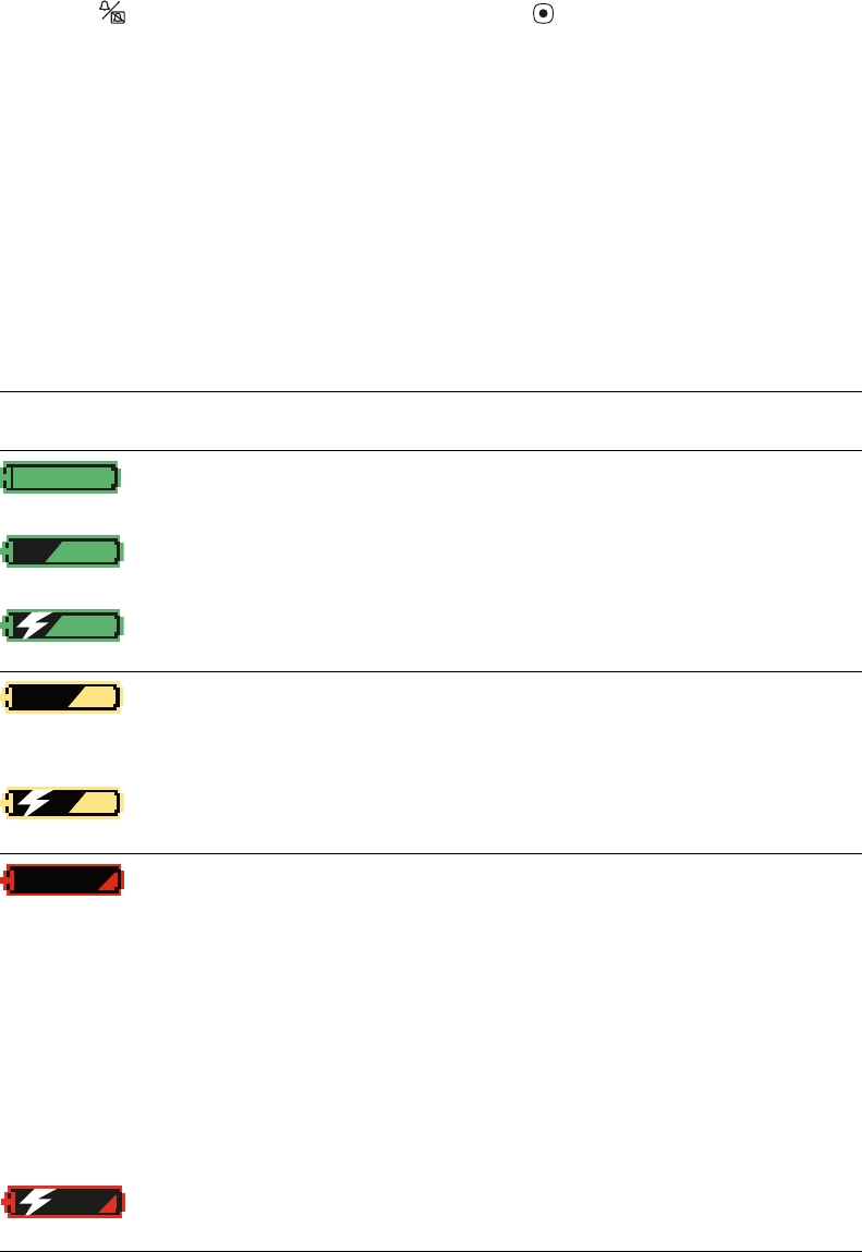
Figure 89. Example Alert Screen
1
40
40/
78
78
80
80
12
12
97
97%
HALL, ROBERT E.
HALL, ROBERT E.
3456187
3456187
3:00:06P
3:00:06P
Adult,
Adult,
Rm 239
Rm 239
HR/min
HR/min
NIBP mmHg (102)
NIBP mmHg (102)
@2:47P Manual
@2:47P Manual
Resp/min
Resp/min
SpO2
SpO2
SpO2
SpO2
2x
2x
II 1mV/cm
II 1mV/cm
Propaq LT
The yellow light flashes during an alert
and while the alert is silenced.
Press to silence the alert tone for
90 seconds.
Text on a yellow field identifies the
alert condition.
X
Resp/min
Resp/min
SpO2
SpO2
II 1mV/cm
II 1mV/cm
HALL, ROBERT E.
HALL, ROBERT E.
3456187
3456187
12:41:32
12:41:32
Adult
Adult
Rm 239
Rm 239
Audible Alarms Silenced
Audible Alarms Silenced
80
80
140/78
140/78
12
12
97
97 %
HR/min
HR/min
NIBP mmHg (102)
NIBP mmHg (102)
@2:47P Manual
@2:47P Manual
EQUIPMENT ALERT
EQUIPMENT ALERT
ECG Fault
ECG Fault
LL Lead Failed
LL Lead Failed
ACKNOWLEDGE
ACKNOWLEDGE
Directions for Use Alarms and Alerts 91
To Respond at the Monitor to an Alert
1. Press to silence the tone for 90 seconds; press to clear the alert.
2. Troubleshoot and correct the problem. (See “Alert Messages and Status Messages”
on page 92.)
To Respond at Acuity to an Alert
For a monitor in communication with Acuity, alarms and alerts can be detected by either
the monitor or Acuity, and are displayed in both places. See Acuity Directions For Use.
About Battery Charge Status
Table 8. Battery Status Indicators
Display Status/Alert
Text
Battery Monitor Recommended
Action
Green
(none) Fully charged Okay None
Green
Partially full Okay None
Green
Partially full; charging Okay None
Yellow
EQUIPMENT ALERT
Low Battery.
Charge battery soon.
Low Can function for up to
30 minutes, but NIBP
is disabled.
Prepare to discontinue
monitoring. If possible,
insert the monitor into a
cradle.
Yellow
Low; charging Normal function. Do not remove the
monitor from the cradle.
Red
EQUIPMENT ALERT
Battery Too Low.
Shutting down.
Almost completely
discharged
Shutting down soon.
Can function for up to
5 minutes, but NIBP is
disabled.
Prepare to discontinue
monitoring. If possible,
insert the monitor into a
cradle.
If this indicator appears
when the monitor is in a
powered cradle, then
the battery is damaged
and must be replaced.
In this case, all stored
patient data will be
deleted when the
monitor is removed
from the cradle.
Red
Almost completely
discharged; charging
Normal function. Do not remove the
monitor from the cradle.

92 Alarms and Alerts Welch Allyn Propaq LT Vital Signs Monitor
Alert Messages and Status Messages
Table 9. Alert Messages and Status Messages
Alert Type Message Possible Cause and Suggested Response
ECG ECG Fault.
XX lead failed.
Lead XX (LA, LL, RA, C, or RL) has very poor contact or no
contact with the patient. Check for proper connection and
replace the electrode if needed.
ECG Fault.
XX, XX leads failed.
Leads XX and XX (any two leads on a 5-lead cable) have very
poor contact or no contact with the patient. Check for proper
connection; replace electrodes if needed.
ECG Fault.
Multiple lead fail.
At least three leads of a 5-lead cable or at least two leads
of a 3-lead cable have very poor contact or no contact with
the patient. Check for proper connection; replace electrodes
if needed.
ECG Fault.
Excessive offset.
At least one channel has excessive offset. At least one
electrode is old, contaminated, or defective. Replace the
electrodes.
ECG Fault.
Cable disconnected.
The ECG cable is unplugged.
NIBP NIBP Fault.
Air leak.
Check hose.
The monitor could not properly inflate the cuff. Check the
hose and cuff for leaks.
NIBP Fault.
Kinked hose.
Check hose.
The monitor could not properly inflate the cuff. Check for a
hose kink between the monitor and the patient.
NIBP Fault.
Overpressure condition.
The pressure in the cuff exceeded the acceptable limits for
the current patient mode. Check the hose and retry the
measurement.
NIBP Fault.
Weak Pulses.
Can’t find Sys/Dia.
Not enough pulses to determine the systolic or diastolic
pressures, but a mean pressure is available. Squeeze all air
from the cuff and reapply it.
NIBP Fault.
Artifact.
Can’t find Sys/Dia.
The systolic or diastolic pressures are unreliable due to
artifact, but a mean pressure is available. Usually caused by
patient motion.
NIBP Fault.
No pulses detected.
The cuff might not be properly applied to the patient, or the
patient might not have detectable pulses due to shock or
arrhythmias.
WARNING The monitor cannot determine whether
this alert has a physiologic cause or a cuff
application cause. Always evaluate the patient for
presence of life-threatening conditions when this
message occurs.
NIBP Fault.
Connect ECG to reduce NIBP artifact.
NIBP artifact prevents a valid reading. Connect ECG
electrodes to improve NIBP measurements. (See “Improving
NIBP Accuracy with Smartcuf” on page 71.)

Directions for Use Alarms and Alerts 93
NIBP Fault.
No valid blood pressure found.
The patient mode setting is incorrect or the wrong hose or
cuff is being used for the current patient mode.
NIBP Fault.
Calibrating.
Please wait.
The monitor periodically calibrates (zeroes) the NIBP
channel to make sure it can properly make NIBP
measurements. No NIBP monitoring can be done until the
calibration is completed. Other normal monitor operation
continues during NIBP calibration.
NIBP Fault.
Calibrating.
Minimize motion.
Motion is detected during a periodic NIBP calibration.
Minimize patient motion or motion on the cuff, or
disconnect the cuff. Motion-generated noise on the
pressure transducer can cause the calibration to continue
indefinitely.
NIBP Fault.
Low battery.
NIBP disabled.
The battery is too far discharged to operate the NIBP
channel. Insert the monitor into a powered cradle.
NIBP Fault.
Service required.
NIBP disabled.
Have the monitor serviced.
NIBP Fault.
Kinked or neonate hose.
A hose is kinked or a neonate hose is detected in the adult
patient mode. Check the hose and the patient mode
selection.
NIBP Fault.
Artifact present.
Minimize motion.
The monitor has detected too much artifact to allow
accurate readings. Take steps to reduce artifact. Position
the patient’s limb away from the body so the applied cuff is
not in contact with the patient’s body or any other object
such as a bed rail.
Network
Communication
Comms Fault.
Check Acuity/network connection.
The monitor detects a network communication problem.
Comms Fault.
Check USB connection.
The monitor detects a problem in communication with the
cradle. Detach and reattach the USB cable.
Not on Network.
Patient info entry not allowed.
You attempted to select the Name, ID, or Rm field on an
Acuity-enabled monitor that is not connected to the
network.
Battery Low Battery.
Charge battery soon.
The monitor battery charge is low, and the monitor will shut
down in 30 minutes or less. Insert the monitor into the
cradle. If no cradle is available, find an alternative method
of monitoring the patient before the monitor shuts down.
Very Low Battery.
Charge battery now.
The monitor battery charge is very low; the monitor will shut
down in 5 minutes or less. Insert the monitor into a cradle or
find another way to monitor the patient before the monitor
shuts down.
Battery Too Low.
Shutting down.
The monitor battery charge is too low to support monitor
function. Monitor operation can continue only after the
battery is recharged or replaced or until the monitor is
inserted in a powered cradle.
Table 9. Alert Messages and Status Messages (continued)
Alert Type Message Possible Cause and Suggested Response

94 Alarms and Alerts Welch Allyn Propaq LT Vital Signs Monitor
Charger Charger Fault.
Service charger.
Service required.
Charger Disabled.
Battery temperature too high or low.
The battery is too cold or too hot to charge. Normalize the
battery temperature before attempting to charge it.
Battery Fault.
Replace battery.
The battery is missing; the battery is discharged too far to
be charged; the charger has timed out; a cell in the battery
pack is overcharged due to cell imbalance; the fuse is
blown. Service required.
SpO2SpO2 Fault.
No sensor detected.
An SpO2 sensor has been disconnected from the monitor
after being connected for more than a few seconds.
SpO2 Fault.
Defective SpO2 sensor.
Replace the sensor.
Resp Resp Fault.
Lead fail.
One or more electrodes have very poor or no contact. Check
for proper connection; replace electrodes if needed.
Resp Fault.
Noisy signal.
Check electrodes.
Electrodes have poor contact and might be dried out.
Replace electrodes.
Resp Fault.
Inappropriate ECG cable.
The ECG cable does not contain 1 kΩ current-limiting
resistors, which are required for Resp operation and to
protect the monitor from damage during defibrillation.
Replace the cable with one of the proper type.
General Multiple Faults. Multiple equipment alerts have been triggered
simultaneously.
WARNING If you acknowledge this alert message
before determining which alerts are triggered, you
cannot identify individual alerts.
Table 9. Alert Messages and Status Messages (continued)
Alert Type Message Possible Cause and Suggested Response