Yaesu Musen 20445X20 AMATEUR RADIO WITH SCANNING RECEIVER User Manual 2
Yaesu Musen Co., Ltd. AMATEUR RADIO WITH SCANNING RECEIVER 2
Contents
User Manual 2
8
Read this information first
Safety Precautions (Be Sure to Read)
Do not perform transmission in a
crowded place for the safety of per-
sons using a medical device such as
a cardiac pacemaker.
The radio wave emitted from this prod-
uct can cause the medical device to mal-
function and result in an accident.
Do not touch any material leak-
ing from the battery pack with bare
hands.
The chemical that has stuck to your skin
or entered your eye can cause chemical
burns. In such a case, consult the doctor
immediately.
Do not solder or short-circuit the ter-
minal of the battery pack.
A fire, leak, overheating, explosion, or igni-
tion can result.
Do not carry the battery pack together
with a necklace, hair pin, or small metal
objects. A short circuit can result.
If it starts thundering when the exter-
nal antenna is used, immediately turn
off this product and disconnect the
external antenna from it.
A fire, electrical shock, or damage may
result.
WARNING
Do not power this transceiver with a
voltage other than the specified pow-
er supply voltage.
A fire, electric shock, or damage may
result.
Do not use the battery pack for any
model other than the specified trans-
ceiver.
A fire, leak, overheating, explosion, or
ignition can result.
This product has a waterproof struc-
ture and conforms to “IPX5” when
the included antenna and battery
pack are installed and rubber caps
are securely attached to the MIC/SP
jack, EXTDC IN jack, DATA terminal,
and micro SD slot. If this transceiver
gets wet, wipe it with a dry cloth, etc.
do not leave it exposed to the mois-
ture.
Leaving this product in a wet condition
can degrade its performance, shorten its
life, or cause a failure or electrical shock.
Do not make very long transmissions.
The main body of the transceiver may
overheat, resulting in a failure or burns.
Do not disassemble or make any al-
teration to this product.
An injury, electric shock, or failure can
result.
Do not handle the battery pack or
charger with wet hands. Do not insert
or remove the power plug with wet
hands.
An injury, leak, fire, or failure can result.
If smoke or strange odor is emitted
from the main body, battery pack,
or battery charger, immediately turn
the transceiver off; remove the bat-
tery pack, and remove the power plug
from the outlet.
A fire, leak, overheating, damage, igni-
tion, or failure can result. Contact the
dealer from which you purchased this
product or Yaesu Amateur Customer
Support.
Do not use the battery pack which is
externally damaged or deformed.
A fire, leak, heating, explosion, or igni-
tion can result.
Do not use any battery charger which
is not specified by Yaesu.
A fire or failure can result.
Application for FCC / IC
FCC ID: K6620445X20
IC: 511B-20445X20
9
Read this information first
Safety Precautions (Be Sure to Read)
Keep the terminals of the battery
pack clean.
If terminal contacts are dirty or corroded,
a fire, leak, overheating, explosion, or
ignition can result.
If charging of the battery pack can-
not be completed within the specified
charging time, immediately remove
the power plug of the battery charger
from the outlet.
A fire, leak, overheating, explosion, or
ignition can result.
CAUTION
Do not dangle or throw this product
by holding its antenna.
This product can hit and injure some-
one. In addition, doing so can result in a
transceiver failure or damage.
Do not use transceiver in a crowded
place.
The antenna can hit someone, resulting
in a injury.
Do not place this transceiver in a
place subject to direct sunlight or
near a heater.
The transceiver can deform or discolor.
Do not place this transceiver in a hu-
mid or dusty place.
A fire or failure can result.
During transmission, keep the anten-
na as far from you as possible.
Long-time exposure to electromagnetic
waves can have a negative impact on
your health.
Do not clean the case with thinner or
benzene.
Use a soft, dry cloth to clean the case.
If you do not use this transceiver for a
long period, turn it off and remove the
battery pack for safety.
Do not drop, strike, or throw the
transceiver.
A failure or damage may result.
Keep magnetic cards and video tape
away from the transceiver.
The data recorded on cash cards or
video tape can be erased.
Do not use the earpiece microphone,
earphones, or headphones at an ex-
tremely high volume level.
Hearing impairment can result.
Keep this product out of reach of chil-
dren.
An injury, etc. can result.
Install the hand strap and belt clip
securely.
If they are installed improperly, the
FT1XDR/DE may fall or drop, resulting
in an injury or damage.
Do not place a heavy object on the
power cord of the battery charger.
The battery cord can be damaged, re-
sulting in a fire or electric shock.
Do not use the included battery char-
ger to charge any battery pack which
is not specified for use with the char-
ger.
A fire can result.
Do not operate the transmitter near
the TV or radio.
Radio disturbance can occur in the
transceiver, the TV, or the radio.
Do not use any products other than
the specified options and accesso-
ries.
A failure can result.
When the battery charger is not in
use, remove its power plug from the
outlet
Application for FCC / IC
FCC ID: K6620445X20
IC: 511B-20445X20

10
Read this information first
Safety Precautions (Be Sure to Read)
Charge the battery pack within the
temperature range from +5 °C to
+35 °C (+41 °F to +95 °F).
Charging the battery pack outside this
temperature range can cause leak,
overheating, decrease in performance,
or reduction in service life can result.
When unplugging the power cord of
the battery charger, be sure to hold
the power plug.
Pulling the power cord can damage it
and cause a fire or electronic shock.
Before discarding the worn battery
pack, affix tape or the like to its ter-
minals.
Before using this transceiver in a
hybrid or fuel-saving car, be sure to
check with the automobile manufac-
turer regarding use of the transceiver
in that car.
Noise generated by an onboard electri-
cal device (inverter, etc.) can disrupt the
normal operation of the transceiver.
Application for FCC / IC
FCC ID: K6620445X20
IC: 511B-20445X20

11
Read this information first
Safety Precautions (Be Sure to Read)
About Waterproong Feature Conforming to IPX5
When the included antenna and battery pack are installed and the MIC/SP jack, EXT
DC IN jack, DATA terminal, and micro SD slot are securely covered with rubber caps,
this product is moisture and splash resistant. To ensure continued waterproofing pro-
tection, be sure to check the following points before use.
m Check for damages, deterioration, and dirt.
Antenna rubber, key switch rubber, MIC/SP jack, EXT DC IN jack, DATA terminal, micro SD
slot rubber cap, and battery pack joint.
m Cleaning
When this product is contaminated with seawater, sand, or dirt, rinse with fresh water, and then
wipe with a dry cloth immediately.
m Recommended maintenance interval
It is recommended that you ask for maintenance of this product when one year has passed
since purchase or previous maintenance or when any damage or deterioration is found. Note
that the maintenance service is subject to fees.
m Do not immerse this product in the following liquids:
Sea, pool, hot spring, water containing soap, detergent, or bath additive, alcohol, or chemicals
m Do not leave this product for a long time in the following places:
Bathroom, kitchen, or humid place
m Other precautions
Since this product is not totally waterproof, it cannot be used in water.
Before Transmitting Radio Waves
If you are informed that the radio waves emitted from your amateur station are interfering
with the TV, radio reception, etc., of a neighbor, you should stop emitting the radio waves,
and determine whether any problem of interference exists, and if necessary resolve the
interference problem.
Application for FCC / IC
FCC ID: K6620445X20
IC: 511B-20445X20
12
Read this information first
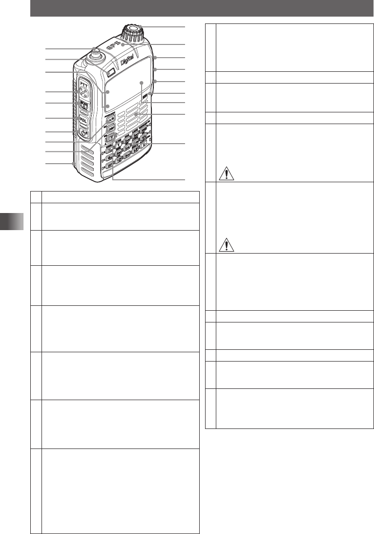
Names and Functions of Controls
①
②
③
④
⑤
⑥
⑦
⑧
⑨
⑩
⑪
⑫
⑬
⑭
⑮
⑯
⑰
⑱
⑲
⑳
①Antenna terminal (SMA)*
②Flashlight (White LED)
• This LED can be used as a small flashlight in a
dark place.
③A-band BUSY/TX lamp
B-band BUSY/TX lamp
These lamps light green during reception and red
during transmission.
④p PTT switch
• While p switch is being pressed: Transmission.
• The Set mode ends when p switch is pressed
during the Set mode.
⑤T switch
USA/EXP version
While T is being pressed: Squelch OFF
European version
While T is being pressed: T.CALL (1750 Hz)
⑥v switch
• While pressing v, turn O: Volume level ad-
justment
• Pressing v during the sound is being muted
cancels the Mute function.
⑦P Power switch
• Press and hold P over 1 second: Power on.
• Press and hold P over 1 second again: Power
off.
• Press P : Key lock
⑧A key (switching between operating bands)
• Pressing A each time switches between A-
band and B-band.
• Press and hold A over 1 second: Changes
the Dual Band Reception mode to the Mono
Band Reception mode.
• While operating the transceiver in the Mono
Band Reception mode, press F and then
A: Zooms in the display view.
⑨M key
• Pressing M each time switches between the
Frequency and BACKTRACK screen.
• Press and hold M over 1 second: Enters the
Set mode.
⑩Battery pack*
⑪O
Turn this dial to change the reception frequency or
select a memory channel.
⑫GPS antenna
⑬MIC/SP jack*
Connect a speaker microphone or earpiece micro-
phone to this jack.
It is not waterproofed when an external micro-
phone is connected.
Do not connect any microphone which is not
specified by Yaesu. A failure can result.
⑭EXT DC IN jack*
• When charging the battery pack, connect the bat-
tery charger (PA-48 or SAD-11B) to this jack.
• In the USA/EXP market, connect an external
power supply adapter with a cigarette lighter
plug (SDD-13) or an external power cable
(E-DC-6) to this jack.
Do not connect any battery charger which is
not specified by Yaesu. A failure can result.
⑮DATA terminal*
• Use this terminal when using a clone function or
updating the firmware.
• Connect the optional camera-equipped micro-
phone (MH-85A11U).
• For how to update the firmware, access our
home page.
⑯Microphone
⑰Display
This LCD displays reception frequencies and vari-
ous settings.
⑱Speaker
⑲15 keys
These keys are used to specify reception/transmis-
sion frequency or select a function.
⑳F switch
• Press F Function switch
• Press and hold F over 1 second: Registers a
frequency to a memory channel.
* When the included antenna and battery pack
are installed and the MIC/SP jack, EXT DC IN
jack, DATA terminal, and micro SD slot are se-
curely covered with rubber caps, the FT1XDR/
DE meets the waterproofing performance con-
forming to IPX5 (See page 11).
Application for FCC / IC
FCC ID: K6620445X20
IC: 511B-20445X20

13
Read this information first
Names and Functions of Controls
KEY
When pressed
When pressed and held
over 1 second
The key is pressed
after F pressed
When entering a
frequency or recalling
a memory CH
When inputting a tag
%Switches between
radio wave types.
— Starts WiRES-X —
DTurns on/off the GM
function.
———
HDetermines the func-
tion selection
Moves the cursor to
the right.
— —
1Number “1” Number “1” — Enables transmission
power level switch-
ing.
2
Number “2” Number “2”, or Upper
or Lower case char-
acters “A”, “B”, “C”,
“a”, “b”, or “c”
—Enables scan opera-
tion.
3
Number “3” Number “3”, or Upper
or Lower case char-
acters “D”, “E”, or “F”,
“d”, “e”, or “f”
—Recalls a preset re-
ceiver memory chan-
nel
4
Number “4” Number “4”, or Upper
or Lower case char-
acters “G”, “H”, or “I”
, “g”, “h”, or “i”
—Enables home chan-
nel selection.
5
Number “5” Number “5”, or Upper
or Lower case char-
acters “J”, “K”, or “L”,
“j”, “k”, or “l”
—Enables reversal
function.
6
Number “6” Number “6” , or Up-
per or Lower case
characters “M”, “N”,
or “O”, “m”, “n”, or “o”
—Enables AF DUAL
function.
7
Number “7” Number “7”, or Upper
or Lower case char-
acters “P”, “Q”, “R”,
or “S”, “p”, “q”, or “r”,
or “s”
—Displays QSO LOG
data.
8
Number “8” Number “8”, or Upper
or Lower case char-
acters “T”, “U”, or “V”,
“t”, “u”, or “v”
— —
9
Number “9” Number “9” , or Up-
per or Lower case
characters “W”, “X”,
or “Y”, “Z”, “w”, “x”,
“y”, or “z”
—Transmits APRS
beacon.
0Number “0” Number “0” — Displays APRS sta-
tions/APRS Message
LIST.
BIncreases the fre-
quency band.
— Enables band scope
function.
Decreases the fre-
quency band.
V
Switches between
the VFO mode and
Memory Channel
mode.
— — Enables dual watch
function.
F—Erases a character
and the cursor moves
to the left.
Enters the Memory
Channel Registration
mode.
—
Application for FCC / IC
FCC ID: K6620445X20
IC: 511B-20445X20
14
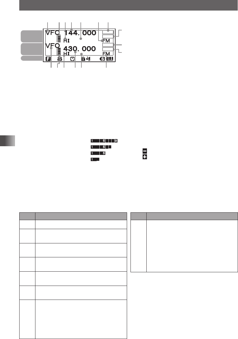
Read this information first
Names and Functions of Controls
①
①②③④⑤⑥
②③④⑤ ⑥⑦
⑧
⑦
⑧
A-band
display area
B-band
display area
Icons
①Displays choice of the VFO mode or MR
(memory channel) mode.
②Displays a sound volume bar graph.
③Displays a transmission power level icon.
④Displays an operating frequency.
⑤S meter: Displays the radio wave strength in
9 steps.
PO meter: Displays the transmission power
level in 4 steps.
H I: High power (5 W)
L 3: LOW 3 power (2.5 W)
L 2: LOW 2 power (1 W)
L 1: LOW 1 power (0.1 W)
⑥Displays the operating mode (radio wave
type).
FM FM (Analog) mode
FM Auto mode (automatic switching
among Analog AM, Analog FM, and
Digital)
DN Wide digital mode (digital communi-
cation using C4FM modulation)
VW Wide digital mode (High quality digi-
tal communication)
⑦Displays a squelch type (See page 84).
TN: Lights up when the tone encoder
function is enabled.
TSQ: Lights up when the tone squelch
function is enabled.
DCS: Lights up when the DCS function is
enabled
RTN: Lights up when the reverse tone
function is enabled.
PR: Lights up when the idle signal
squelch function is enabled.
PAG: Lights up when the pager is en-
abled.
Displays the APRS baud rate (APRS function
instruction manual).
⑧Displays a shift direction during repeater
operation (See page 40).
: Minus shift
: Plus shift
@: Split operation
b appears when the bell alarm function is
active (See page 89).
Description of Icons
Icon Description of operation
f
Lights when a function key is pressed.
dLights when the DTMF function is
enabled (See page 79).
[Lights when the APO function is active
(See page 127).
lLights when the LOCK function is active
(See page 39).
]Lights when the MUTE function is active
(See page 35).
sLights when a micro SD memory card is
inserted.
H I
Displays the transmission power level
(See page 36).
H I: High power (5 W)
L 3: LOW 3 power (2.5 W)
L 2: LOW 2 power (1 W)
L 1: LOW 2 power (0.1 W)
Icon Description of operation
<
Displays battery condition.
<: Full battery power
>: Enough battery power
?: Low battery power
_: Poor battery power. Charge
battery.
_ : Charge battery immediately
(blink).
Application for FCC / IC
FCC ID: K6620445X20
IC: 511B-20445X20