Yaesu Musen 20445X20 AMATEUR RADIO WITH SCANNING RECEIVER User Manual 5
Yaesu Musen Co., Ltd. AMATEUR RADIO WITH SCANNING RECEIVER 5
Contents
User Manual 5

60
Scanning Function
Using the Scanning Function
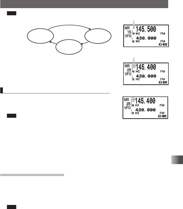
Tips • Turn O clockwise.: Scanning is performed toward higher memory channel numbers.
Turn O counterclockwise: Scanning is performed toward lower memory channel numbers.
• When a signal is received during scanning, scanning stops for 5 seconds and this frequency
is received.
• When scanning is suspended, the decimal point blinks and the LCD stays lit.
• After receiving the frequency for 5 seconds, scanning resumes.
• To stop scanning, press p.
Tips
• Even during scanning, you can adjust the squelch in the following procedure:
Press F → Press T. → Turn O to adjust the squelch.
• During scanning, you can finish the squelch adjustment in the following procedure:
Press F → Press T.
• When a memory channel is recalled, the regular memory channels (memory channel numbers 1-900)
are scanned.
• When a memory bank is recalled, only the memory channels in the memory bank are scanned.
• For the operation to perform when scanning stops, see [Selecting a Reception Method When Scan-
ning Stops] on page 59.
• Press and hold M over 1 second to select the Set mode option, and then select the following setting
items for more convenient use:
[8 CONFIG] → [3 BEEP] → [EDGE]: Emits a beep when the frequency band edge is reached.
[8 CONFIG] → [3 BEEP] → [SELECT]: Prevents a beep from being emitted when scanning stops.
[5 SCAN] → [2 SCAN LAMP]: Prevents the LCD from being lit when scanning stops.
[5 SCAN WIDTH] → [5 SCAN]: Range for scanning can be selected.
Specifying a Skip/Selected Memory Channel
You can specify two types of memory channels, a skip memory channel and a selected
memory channel, for effective memory channel scanning.
Skip memory channel: You can specify a memory channel that need not be scanned dur-
ing memory channel scanning.
Selected memory channel: You can specify selected memory channels so that only the
specific memory channels are scanned during memory scan-
ning.
1 Switch to the Memory mode, and then recall the memory
channel you want to specify as a skip memory channel or a
selected memory channel.
2 Press and hold M over 1 second.
Enters the Set mode.
3 Turn O to select [3 MEMORY].
4 Press H.
5 Turn O to select [5 MEMORY SKIP].
6 Press H.
7 Turn O to select [OFF], [SKIP], or [SELECT].
8 Press p to save the setting and exit from the Set mode.
Application for FCC / IC
FCC ID: K6620445X20
IC: 511B-20445X20
61
Scanning Function
Using the Scanning Function
Tips To cancel a skip/selected memory channel, select [OFF].
When it is canceled, the ◄ icon on the LCD disappears.
Scanning Only the Selected Memory Channel
1 Switch to the Memory mode, and then recall the selected
memory channel.
2 Press F and then 2.
Tips • Scanning (SCAN) is performed toward higher memory chan-
nel numbers.
• Only the selected memory channel is scanned.
• If a signal is received during scanning, a beep is emitted and scanning stops for 5 seconds to
receive the current frequency.
• When scanning is suspended, the decimal point blinks and the LCD stays lit.
• After receiving the frequency for 5 seconds, scanning resumes.
• To cancel scanning, press p.
• You can select the range for scanning by selecting [5 SCAN] → [5 SCAN WIDTH] in the Set
mode.
Scanning a Memory Bank
Only the memory channels in the recalled memory bank can be scanned.
1 Press V to enter the Memory mode.
2 Press B to enter Recall a memory bank.
Pressing B each time toggles between [MEMORY NO] and [BANK (No.)].
Tips To recall another memory bank, press F and then B.
3 Turn O to select a memory bank.
Select a memory bank from BANK1 through BANK 24.
4 Press B.
The selected memory bank is determined.
5 Press F and then 2.
Scanning (SCAN) is performed toward higher memory channel numbers.
Lights when a skip memory
channel is specified
Blinks when a select
memory channel is specified
Skip memory
channel
[SKP]
Selected memory
channel
[SELECT]
O
OFF
Application for FCC / IC
FCC ID: K6620445X20
IC: 511B-20445X20
62
Scanning Function
Using the Scanning Function
Tips • Turn O clockwise: Scanning is performed toward higher memory channel numbers.
Turn O counterclockwise: Scanning is performed toward lower memory channel numbers.
• When a signal is received during scanning, scanning stops for 5 seconds and this frequency
is received.
• When scanning is suspended, the decimal point blinks and the LCD stays lit.
• After receiving the frequency for 5 seconds, scanning resumes.
• To stop scanning, press p.
• You can select the range for scanning by selecting [5 SCAN] → [5 SCAN WIDTH] in the Set
mode.
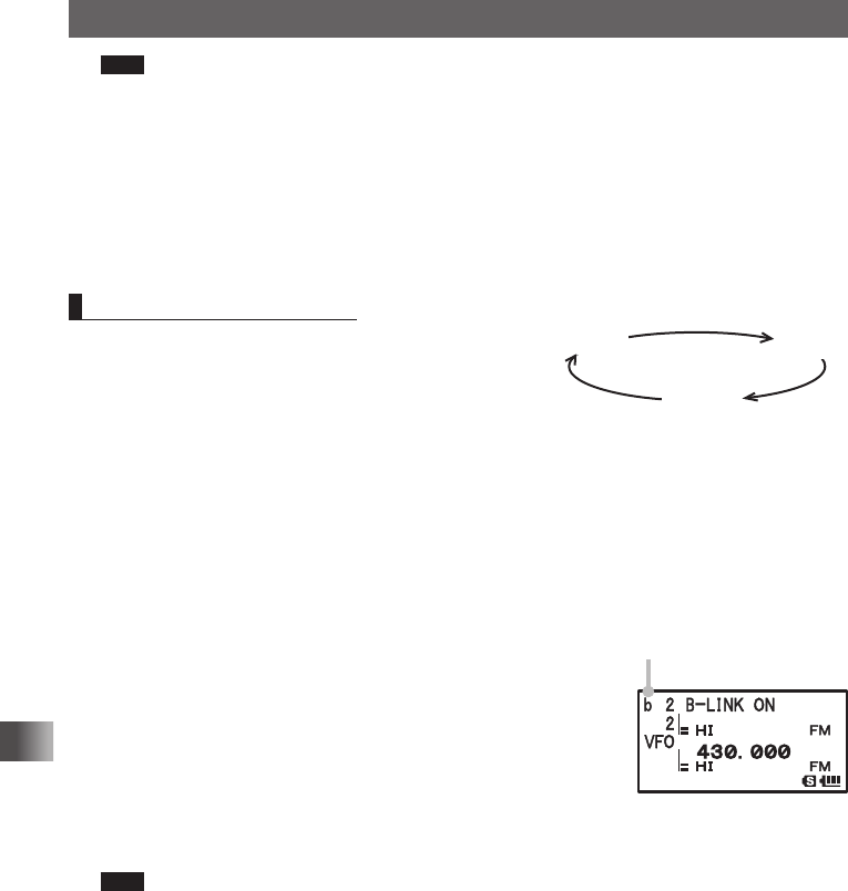
Memory Bank Link Scan
During regular memory bank scanning, only the
memory channels assigned to the recalled memory
bank are scanned. During memory bank link scan-
ning, memory channels registered in two or more
previously specified banks can be scanned.
1 Press V to enter the Memory mode.
2 Press B to enter Recall a memory bank.
3 Press F and then B.
4 Turn O to select a memory bank.
Select a memory bank subject to memory bank link scanning.
5 Press V to select a Memory bank link.
The memory bank number changes from [B] to [b], indicat-
ing that the bank link has been activated
6 Repeat steps 4 to 5 to select another memory bank.
7 Press B.
The memory banks subject to memory bank link scanning
are determined.
8 Press F and then [2].
Scanning (SCAN) is performed toward higher memory channel numbers.
Tips • Turn O clockwise.: Scanning is performed toward higher memory channel numbers.
Turn O counterclockwise: Scanning is performed toward lower memory channel numbers.
• When a signal is received during scanning, scanning stops for 5 seconds and this frequency
is received.
• When scanning is suspended, the decimal point blinks and the LCD stays lit.
• After receiving the frequency for 5 seconds, scanning resumes.
• To stop scanning, press p.
• You can select the range for scanning by selecting [5 SCAN] → [5 SCAN WIDTH] in the Set
mode.
BANK1 BANK10
BANK24
The memory bank number
changes from [B] to [b].
Application for FCC / IC
FCC ID: K6620445X20
IC: 511B-20445X20
63
Scanning Function
Using the Scanning Function
Canceling Bank Link Scanning
1 Press F and then B.
2 Recall the memory bank for which bank link scanning was specified.
3 Press V.
The memory bank number changes from [b] to [B], indicating that the bank link has
been deactivated.
Programmable Memory Channel Scan (PMS)
Registering to a Programmable Memory Channel
50 sets of PMS memory channels (L1/U1 to L50/U50) are available.
Specify the lower limit frequency of the frequency range you want to scan for memory
channel [L], and the upper limit frequency for [U].
Enter a number between 1 and 50 for . Use the same number for the lower and upper
limit memory channels.
Specify the lower limit frequency and upper limit frequency for the PMS memory channel
(See page 43).
PMS memory channels are located next to the last memory channel.
Pressing M scans PMS memory channels quickly in steps of 100 memory channels.
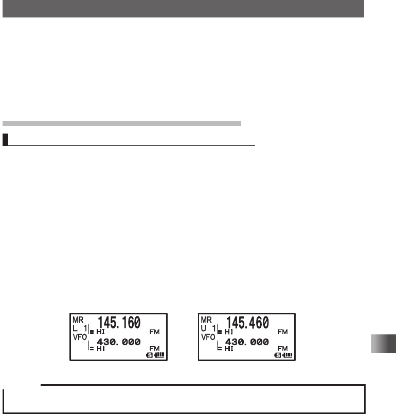
Example: When registering the lower limit frequency 145.160 MHz and the upper limit
frequency 145.460 MHz to a PMS memory channel.
Lower limit frequency L1 Upper limit frequency U1
Caution
When the upper and lower limit frequencies have been set in different step, be sure to set 100 kHz or
more in between.
Application for FCC / IC
FCC ID: K6620445X20
IC: 511B-20445X20
64
Scanning Function
Using the Scanning Function
Performing Programmable Memory Channel Scan
The programmable memory channel scan allows you to scan a specified frequency range
within the same frequency band.
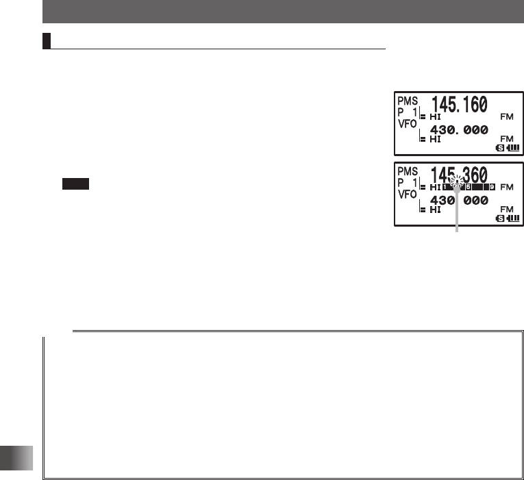
1 Switch to the Memory mode.
Recall a PMS memory channel to which the lower limit fre-
quency or upper limit frequency is registered.
2 Press F and then 2.
Programmable memory channel scanning starts.
Tips • Turn O clockwise: Scanning is performed toward higher fre-
quencies.
Turn O counterclockwise: Scanning is performed toward
lower frequencies.
• When a signal is received during scanning, scanning stops for
5 seconds and this frequency is received.
• When scanning is suspended, the decimal point blinks and the LCD stays lit.
• After receiving the frequency for 5 seconds, scanning resumes.
• To stop scanning, press p.
Tips
• When a skip memory channel is specified for [L] or [U] or when the lower/upper limit frequency is
not properly specified, program memory channel scanning is not performed properly.
• Press and hold M over 1 second to select the Set mode option and then select the following setting
items for more convenient use:
[8 CONFIG] → [3 BEEP] →[EDGE]: Emits a beep when the frequency band edge is reached.
[5 SCAN] → [2 SCAN LAMP]: Prevents the LCD from being lit when scanning stops.
• Even during scanning, you can adjust the squelch in the following procedure:
Press F → Press T → Turn O to adjust the squelch.
• During scanning, you can finish the squelch adjustment in the following procedure:
Press F → Press T.
Decimal point blinks.
Application for FCC / IC
FCC ID: K6620445X20
IC: 511B-20445X20
65
Using the Digital GM Function
Using the Digital GM Function
(Digital Group Monitor Function)
What is the GM function?
The Digital GM (Group Monitor) Function automatically checks if there is another trans-
ceiver operating on the same frequency with the GM function within transmission range,
and displays the direction, distance and other information for each detected callsign on
the LCD. This convenient function not only lets you know if a friend is within transmission
range, but also enables instant confirmation of position information between group mem-
bers. Furthermore, by using this function, you can send messages and images between
group members.
Caution
The GM function does not function in the analog mode. Using the % key, switch the communication
mode to AMS (Auto Mode Select Function) or digital mode.
Tip
When transmitting image data while GM function is active, the transmission mode automatically switches
to FR mode (High Speed Data Communication Mode).The transmission mode will automatically return
to the previous V/D mode (Voice/Data Simultaneous Communication Mode).
Standard Operation of the GM Function
Using the GM Function
There are 2 ways of using the Digital GM Function.
(1) Show all stations (up to 24 stations) operating with the GM function.
(2) Register IDs of friends in a group and use it only between registered members.
Displaying all stations (up to 24 stations) operating with the GM function.
1 Adjust frequency to A band.
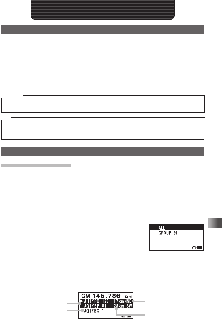
2 Press D to open the group list.
3 Turn O to select [ALL].
4 Press H.
The ID, distance, and direction of all stations (up to 24) with-
in communication range operating with the GM function on
the same frequency are displayed.
If there are more than 3 stations, turn O to scroll through
the display.
When the GM function is active, not only can you verify if a station is in or out of com-
munication range but the position (direction and distance) information as well.
Directio
n
In range
Out of rang
e
Distanc
e
Example of display when ALL is selected
Group List Screen
Application for FCC / IC
FCC ID: K6620445X20
IC: 511B-20445X20
66
Using the Digital GM Function
Standard Operation of the GM Function
Registering IDs of friends in a group and using GM function only between regis-
tered members
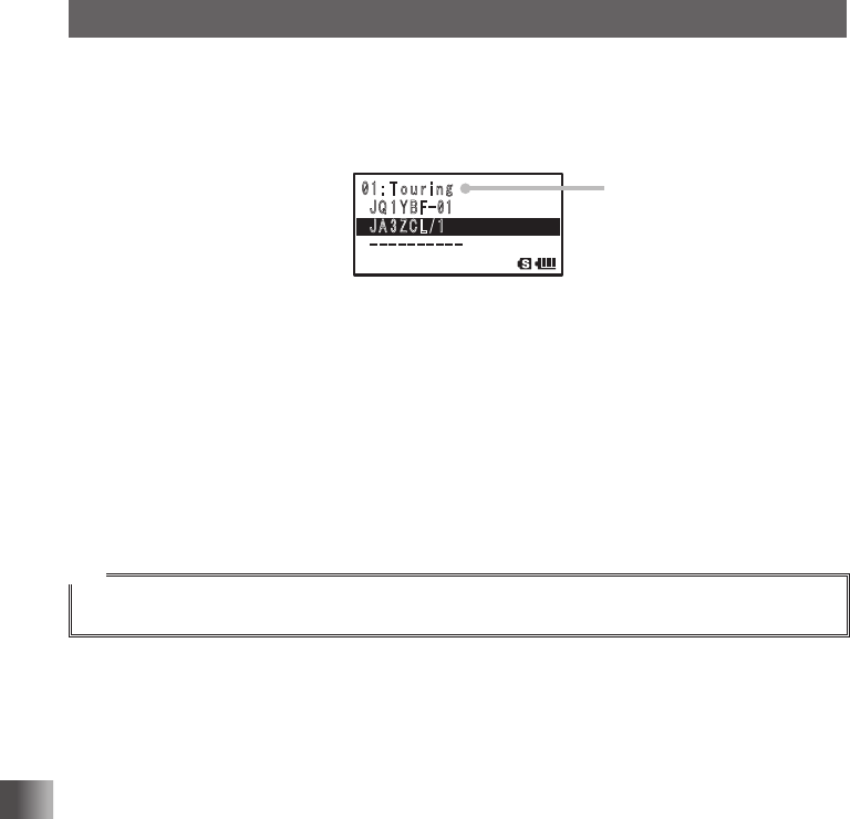
Set a group with a name such as [Touring] or [Camp], and only show members registered
to that group.
䎓 䎔 䎝䫹䎷
䏒 䏘 䏕 䏌 䏑 䏊
䎃䎭 䎴 䎔 䎼 䎥 䎩
䙵
䎓 䎔
䎃䎭 䎤 䎖 䎽 䎦 䎯
䎒
䎔
䎐䎐䎐䎐䎐䎐䎐䎐䎐䎐䎐䎐䎐
䎃䎕
Group Name
Example of display when Group is set
For group setting and instruction on how to register members to a group, refer to the GM
function instruction manual (please download it from our company website).
Turning the GPS Function OFF
Press D.
The GM function is deactivated and the transceiver returns to the state previous to when
GM function was activated.
Tip
With the GM function, data such as messages and images can be transmitted between members.
For details, refer to the GM function instruction manual (please download it from our company website).
Application for FCC / IC
FCC ID: K6620445X20
IC: 511B-20445X20
67
Using the APRS Function
Using the APRS Function
What is the APRS (Automatic Packet Reporting System)?
Although there are several functions that display position information using GPS in ama-
teur radios, the APRS is data communication system that transmits data such as position
information and messages using a format proposed by Bob Bruninga of WB4APR.
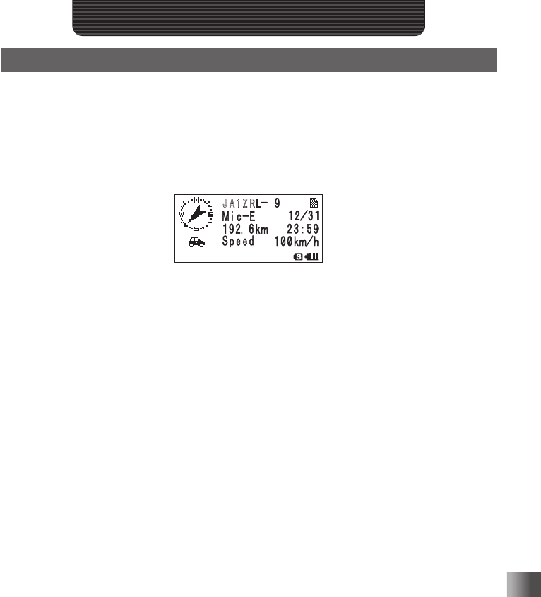
Upon receiving an APRS signal from the remote station, information such as direction and
distance to the remote station from your station and speed of the remote station appear
on the LCD of your transceiver.
䎭 䎤 䎔 䎽 䎵 䎯
Example of display when APRS signal is received
The settings (initial settings) such as callsign and symbol for your station must be applied
before using the APRS function.
For details, refer to the APRS function instruction manual (please download it from our
company website).
Application for FCC / IC
FCC ID: K6620445X20
IC: 511B-20445X20
68
Using the GPS Function
Using the GPS Function
What is GPS?
GPS (Global Positioning System) is a space-based satellite navigation system that pro-
vides location and time information anywhere on the earth. It was developed by the U.S.
Department of Defense as a military system. It receives signals from three or more of
about 30 GPS satellites flying at an altitude of about 20,000 km, and displays the current
position (latitude, longitude, and altitude) within a tolerance of several meters. In addition,
GPS can receive the exact time from the satellite’s onboard atomic clock.
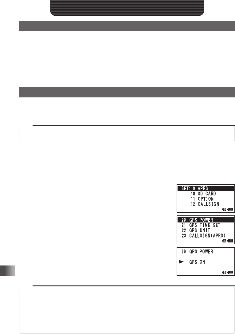
Activating the GPS Function
To activate the GPS function, select [9 APROS] → [23GPS POWER], and then select
[GPS ON] in the Set mode.
Tips
• Default: ON
When the GPS function on the transceiver is turned ON, internal clock settings and posi-
tion settings for your station are automatically obtained from the GPS data.
1 Press and hold M for over 1 second to enter the Set mode.
2 Turn O to select [9 APRS].
3 Press H.
4 Turn O to select [20 GPS POWER].
5 Press H.
6 Turn O to select [GPS ON].
7 Press p to set the GPS Function to ON, and exit the Set
mode.
Tips
• Tip Information about the current positions of radio stations provided by GPS can be registered to
10 memory channels (P1 to P10). Registered position information can be used to set the position of
your station.
• When the GPS function is active, the power consumption increases by about 40 mA. As a result, the
battery life is reduced by about 20% compared to when the GPS function is deactivated.
• To use the GPS function during APRS operation, be sure to select [9 APRS] → [24MY POSITION],
and then select [GPS] in the Set mode.
Application for FCC / IC
FCC ID: K6620445X20
IC: 511B-20445X20
69
Using the GPS Function
Method of Positioning by GPS
Displaying Current Position Information of Your Station
1 Turn on the transceiver.
2 Press and hold M for over 1 second to enter the Set mode.
3 Turn O to select [1 DISPLAY].
4 Press H.
5 Turn O to select [1 GPS POWER].
6 Press H.
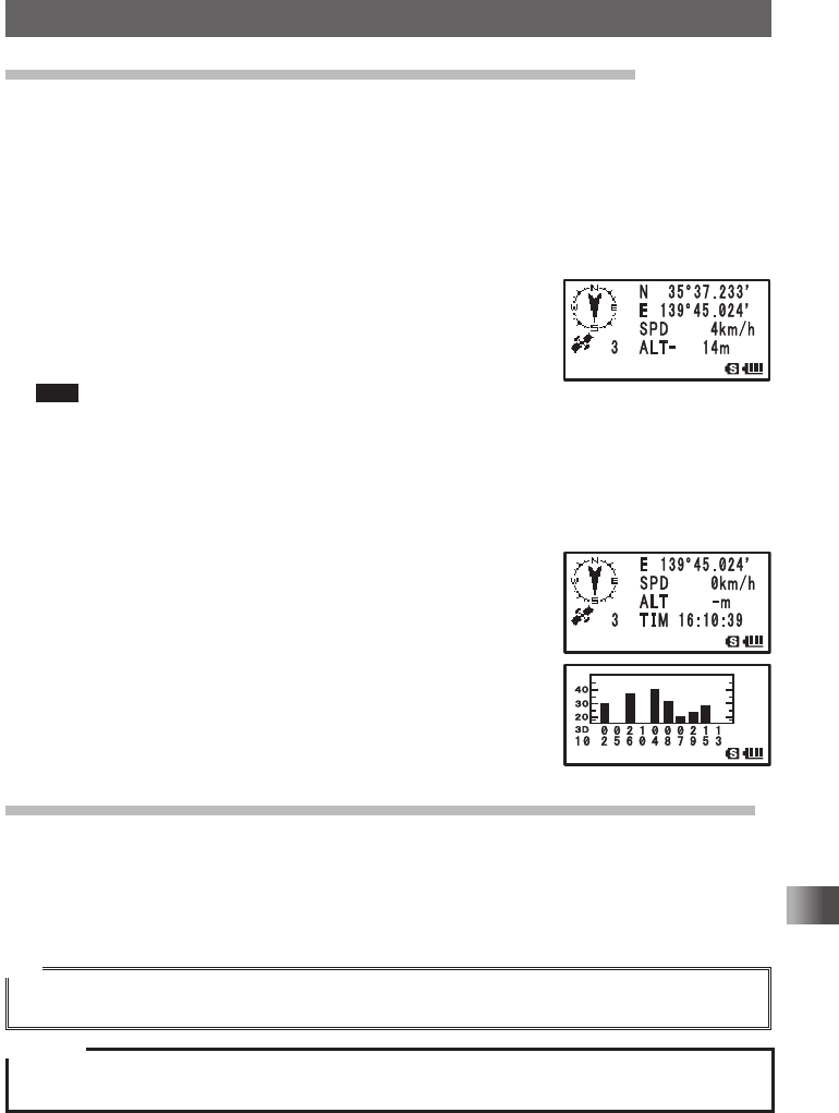
7 GPS data appears on the LCD.
An arrow icon (the direction in which you are heading), your
current position, number of satellites, longitude, latitude,
and altitude appear on the LCD.
Tips • The arrow icon (the direction in which you are heading) will not
appear and the latitude/altitude blinks until GPS satellite data is acquired.
• When GPS satellite data has been acquired, the arrow icon (the direction in which you are
heading) will appear, the latitude/altitude will change from blinking to lit, and your current posi-
tion will be displayed.
• If acquisition of GPS satellite data is interrupted due to an obstacle, such as a building or tun-
nel, only the arrow icon (the direction in which you are heading) disappears.
8 Press O to scroll the screen, and display the current time.
Pressing O again displays GPS data.
The GPS screens will transition each time H is pressed.
9. Press p.
The screen returns from the GPS screen to the normal fre-
quency display. (Not return to the transmission state)
Displaying Position Information of Remote Station in Digital Mode
With the V/D mode C4FM digital, because GPS position information is transmitted si-
multaneously with voice signals, the direction and position of the remote station can be
displayed in real-time even while communicating.
For details, see “Real-Time Navigation Function” on page 73.
Tip
• Even if the GPS function of your station is set to OFF, position information of the remote station can
be displayed in V/D mode.
Caution
If the GPS function is not active, the remote station will not be able to acquire position information for
your station.
Application for FCC / IC
FCC ID: K6620445X20
IC: 511B-20445X20