Yaesu Musen 20445X20 AMATEUR RADIO WITH SCANNING RECEIVER User Manual 6
Yaesu Musen Co., Ltd. AMATEUR RADIO WITH SCANNING RECEIVER 6
Contents
User Manual 6

70
Using the GPS Function
Method of Positioning by GPS
About Positioning by GPS
“Positioning” refers to calculation of your current position from the satellite orbit
information and radio propagation time. At least three satellites need to be acquired for
successful positioning. If positioning fails, move away from buildings as far as possible
and stand in an area with open sky.
● About errors
A positioning error by several hundred meters can occur due to the environmental
conditions. Under favorable conditions, positioning can be performed successfully
using only three satellites. However, under the following poor conditions, the positioning
accuracy can decrease or positioning can fail.
- Between tall buildings
- Narrow paths between buildings
- Indoors or in close vicinity to large buildings
- Beneath bridges or high-voltage lines
- Between trees such as in forests or woods
- Inside tunnel or underground
- Usage behind heat reflective glass
- Areas with strong magnetic fields.
● Searching for satellites when using the GPS function for the first time each
day
When you use the GPS function for the first time after purchase or the first time in the
day, a few minutes are required to search for satellites. Also, when using the GPS
function after turning off the transceiver for several hours, a few minutes may be
required to search for satellites.
Application for FCC / IC
FCC ID: K6620445X20
IC: 511B-20445X20

71
Using the GPS Function
Method of Positioning by GPS
Saving GPS Information (GPS Log Function)
Position information from the GPS can be saved periodically to the microSD memory
card.
Using the saved data and a personal computer, tracks can be displayed with commer-
cially sold map software*.
* Map software, and methods of use are not supported by YAESU.
1 Check that the GPS function is active.
If it is not active, refer to page 68 and enable the GPS function.
2 Press M for over 1 second.
3 Turn O to select [8 CONFIG].
4 Press H.
5 Turn O to select [6 GPS LOG].
6 Press H.
7 Turn O to select the interval for saving data.
OFF / 1 sec / 2 sec / 5 sec / 10 sec / 30 sec / 60 sec
Position information is not saved if OFF is selected.
8 Press p to enable the GPS log function and exit from the Set mode.
Tip
• Position information will continue to be saved unless “OFF” is selected in step 7, shown above, or the
power of the transceiver is turned off.
• If “ON” is selected again in step 7, shown above, or the power for the transceiver is turned on, position
information will start being saved to a differently named file.
Checking Tracks on a PC
1 Turn the transceiver off.
2 Remove the microSD.
3 Connect the microSD card to a PC using a commercially sold memory card reader.
4 Open the folder named [FT1D] within the microSD memory card.
5 Open the folder named [GPSLOG].
Data is saved with the name [GPSyymmddhhmmss.log].
The [yymmddhhmmss] part of the name represents year (yy), month (mm), day (dd),
hour (hh), minute (mm), and second (ss).
Tip
• Tracks can be displayed on a personal computer using commercially sold map software by importing
the GPS data.
• For information on importing and using the GPS data, please refer to the operation manual for the
map software being used.
Application for FCC / IC
FCC ID: K6620445X20
IC: 511B-20445X20
72
Using the GPS Function
Explanation of GPS Screen and Operation
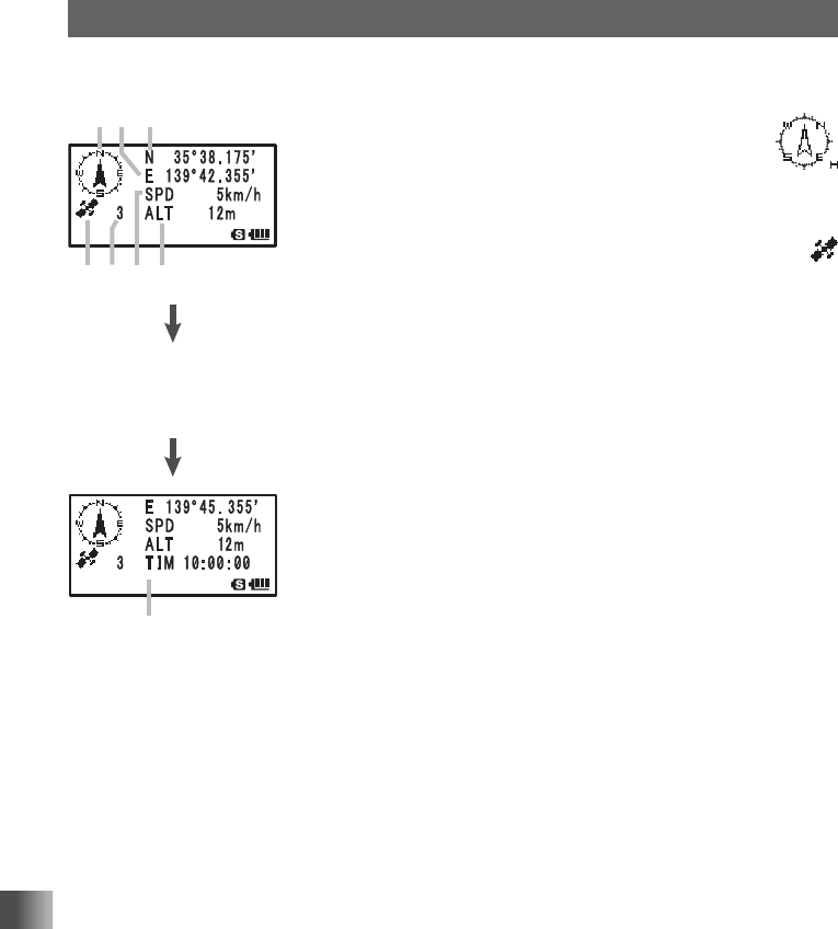
Activating the GPS function displays the following information on the LCD.
①
②
⑧
③ ⑥ ⑦
⑤ ④
Press A to scroll the
screen until the current
time appears.
① Compass: North-UP (North is always up)
Heading-UP: Heading-UP: (When B is
pressed, the direction in which
you are heading is always up. A
white arrow icon appears. [H] ap-
pears at the lower right of the
compass icon.
② Positioning: When at least three satellites have been acquired,
appears.
This icon does not appear on the LCD if the transceiver
cannot acquire at least three satellites.
③ Number of
satellites:
Displays the number of acquired satellites.
④ Latitude: The current position appears using north (N) or south (S)
latitude.
Display format: X DD° MM. MMM
X: X=N: North latitude, X=S: South latitude
DD: Degree
MM.MMM: Minute
Example: N 35° 38.250 (35 degrees, 38 minutes, 15 sec-
onds north latitude)
⑤ Longitude: The current position appears using east (E) or west (S)
longitude.
Format: X DDD° MM. DMMM
X: X=E: East longitude, X=W: West longitude
DDD: Degree
MM.MMM: Minute
Example: E 139° 42.500 (139 degrees, 42 minutes, 30
seconds east latitude)
⑥ Speed: The speed at which you are moving appears.
Format: SPD aaakm/h
Example: SPD 5 km/h
⑦ Altitude: The altitude of the current position of your radio station
appears.
Format: ALT aaaaam
Example: ALT 20m
⑧ Time: The current time set by GPS appears.
Format: aa (hour): bb (minute): cc (second)
Example: 23:59:59 (23 hours 59 minutes 59 seconds)
* When an external GPS device is connected to
the data terminal, the time appears as follows:
aa (hour): bb (minute)
Application for FCC / IC
FCC ID: K6620445X20
IC: 511B-20445X20

73
Using the GPS Function
Explanation of GPS Screen and Operation
Tips
• You can change the unit of GPS data by selecting [9 APRS] → [22 GPS UNIT] in the Set mode.
• When the GPS function is used, the accurate time data (date and time) obtained from GPS appears
on a 24 hour basis. This time data is reflected in the time data displayed on the GPS and APRS
screens.
• You can change the geodetic system of the built-in GPS unit by selecting [9 APRS] → [19 GPS
DATUM] in the Set mode. However, since APRS uses the geodetic system of WGS-84, it is recom-
mended not to change it.
• You can set the time zone by units of 30 minutes by selecting [9 APRS] → [28 TIME ZONE] in the
Set mode (Default: UTC +0:00).
• When the GPS function is active, the power consumption increases by about 30 mA. As a result, the
battery life is reduced by about 20% compared to when the GPS function is deactivated.
• You can obtain position information from a external GPS device by selecting [9 APRS] → [17 COM
PORT SETTING] and then setting [INPUT] to [GPS] in the Set mode. In this case, the data obtained
from the internal GPS is disabled.
• When using an external GPS device, keep it away from the transceiver.
Smart Navigation Function
Using the Smart Navigation Function
There are 2 methods of navigation with the Smart Navigation function.
(1) Real-time navigation function
(2) Backtrack function
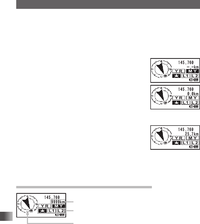
Real-Time Navigation Function
GPS position information and voice signals are simultaneously transmitted in the V/D
mode of C4FM digital.
For this reason, the position and direction of the remote station can be displayed in real-
time even during communication.
1 Press M to open the GPS screen.
2 Turn O to select [YR].
The distance and direction to the remote station operating on the same frequency in
the V/D mode is displayed.
Display of remote station position
Distance to remote statio
n
Direction display
3 Press M.
The screen returns from the navigation screen to the normal frequency display.
Application for FCC / IC
FCC ID: K6620445X20
IC: 511B-20445X20
74
Using the GPS Function
Smart Navigation Function
Backtrack Function
By registering a point of departure beforehand, the distance and direction to the regis-
tered position from your current position can be displayed in real-time.
Registering your current position (point of departure) (up to 3 positions can be
registered)
1 Press M to open the Backtrack screen.
2 Turn O to select [MY].
3 Press H to display the position information of your station.
4 Turn O to select a mark to register from [I], [L1], and [L1].
5 Press H to register the position information to the select-
ed mark and return to the BACK TRACK function screen.
6 Press M to return from the backtrack screen to the normal
frequency display.
Using the Backtrack Function
1 Press M to open the Backtrack screen.
2 Turn O to select [I], [L1] or [L2].
Select the mark with the registered position you would like to
backtrack.
The registered position (departure point) is in the direction
of the arrow within the circle. Walk forward so that the arrow
stays pointing up on the screen.
3 Press M to return from the backtrack screen to the normal frequency display.
To verify the position again, press [DISP] to open the backtrack screen.
Description of the BACK TRACK Function Screen
Distance to the registered position
Registered position mark
Direction to the registered position
Application for FCC / IC
FCC ID: K6620445X20
IC: 511B-20445X20
75
Convenient Functions
Convenient Functions
Dual Reception (DW) Function
The FT1XDR/DE is equipped with the following 3 types of Dual Reception Functions:
(1) VFO Dual Reception
(2) Memory Channel Dual Reception
(3) Home Channel Dual Reception
The transceiver checks the standby side signal reception over the frequency registered
to the selected memory channel (Priority Memory Channel) once approximately every 5
seconds. When the transceiver detects signal reception on the standby side, it starts sig-
nal reception over the frequency registered to the selected memory channel.
Even while receiving a signal over the frequency registered to a priority memory channel
on the standby side, pressing p disables the Dual Reception function and allows for
transmission over the former active side frequency.
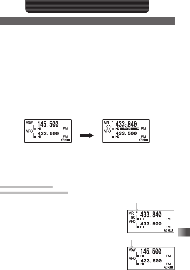
Example: Checking signal reception over a frequency registered to the priority memory
channel [90] (standby side), while receiving signal over [145.500 MHz] (active
side).
Frequency over which a signal is
being received.
The transceiver monitors signal re-
ception over the frequency registered
to the Priority Memory Channel [90]
(standby) and checks it in intervals of
approximately 5 seconds.
When the transceiver receives a signal
over the frequency registered to the pri-
ority memory channel [90], dual recep-
tion stops and signal reception switches
to [90] (standby).
VFO Dual Reception
VFO mode → Priority memory channel
1 Switch to the Memory mode.
2 Press and hold F for over 1 second to enter the Write
mode; F and the channel number blink on the LCD.
3 Turn O to select a memory channel, then press and hold
B for over 1 second.
Select a memory channel to prioritize for signal reception
(Priority Memory Channel). The “P” appears on the LCD.
4 Turn O to select a frequency for signal reception.
Select a frequency for continual signal reception in VFO
mode (active side).
5 Press F and then V to start Dial Dual Reception, and
[VDW] appears on the LCD.
6 Press V stop the Dial Dual Reception.
“P” is displayed.
“VDW” is displayed.
Application for FCC / IC
FCC ID: K6620445X20
IC: 511B-20445X20
76
Convenient Functions
Dual Reception (DW) Function
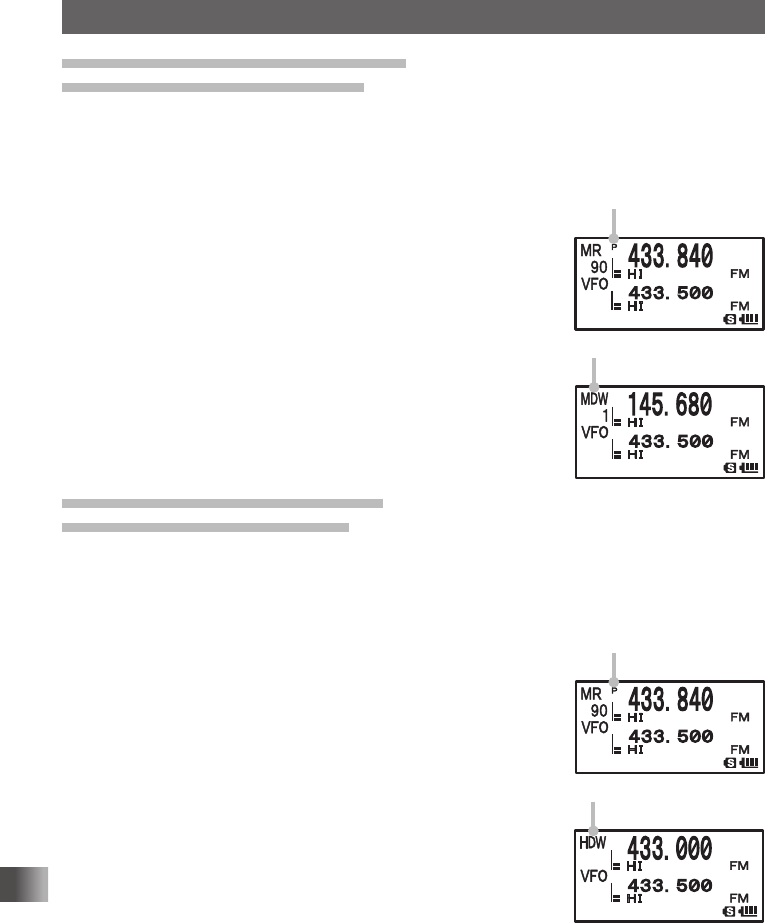
Memory Channel Dual Reception
Memory channel → Priority memory channel
1 Switch to the Memory mode.
2 Press and hold F over 1 second to enter the Write mode;F and the channel num-
ber blink on the LCD.
3 Turn O to select a memory channel and press B.
Select a memory channel to prioritize for signal reception
(Priority Memory Channel) (standby side). The “P” appears
on the LCD.
4 Select a memory channel for signal reception.
Select a memory channel for signal reception at all times
(active side).
5 Press F and then V to start Memory Channel Dual Re-
ception; and [MDW] appears on the LCD.
6 Press V to stop the memory channel dual reception.
Home Channel Dual Reception
Home channel → Priority memory channel
1 Switch to the Memory mode.
2 Press and hold F over 1 second to enter the Write mode.
F and the channel number blink on the LCD.
3 Turn O to select a memory channel and press B.
Select a memory channel to prioritize for signal reception
(Priority Memory Channel) (standby side). The “P” appears
on the LCD.
4 Press F and then 4 to recall a HOME channel (active
side).
5 Press F and then V.
HOME Channel Dual Reception starts and [MDW] appears
on the LCD.
6 Press V to turn home channel dual reception OFF.
“P” is displayed.
“MDW” is displayed.
“P” is displayed.
“HDW” is displayed.
Application for FCC / IC
FCC ID: K6620445X20
IC: 511B-20445X20

77
Convenient Functions
Dual Reception (DW) Function
Caution
Be sure to set a memory channel as the Priority Memory Channel for standby before using this function.
Tips
• The Priority Memory Channel is set to the Memory Channel number 1 by default.
• Pressing and holding M over 1 second and changing the Set mode option allows you to use this
function more conveniently.
[5 SCAN] → [1 DW TIME]: The interval for monitoring the Priority Memory Channel can be changed.
[5 SCAN] → [4 SCAN RESUME]: The resumption conditions for Dual Reception can be changed.
• The combination of the frequency bands and modes of the frequency for the Priority Memory Channel
(standby side) and the frequency for continual signal reception (active side) can be freely changed.
AF-DUAL Function for simultaneous signal reception over the oth-
er frequency while listening to the radio
The AF-DUAL Reception Function allows reception of a radio broadcast, while standby
reception of A-band or B-band frequency (or frequency registered to a memory channel)
is active. When standby reception is active, voice received over that frequency cannot
be heard, however if a voice signal is detected, the reception of the radio broadcast will
be paused and voice will be heard. Although there is a similar function in Dual Reception
(See page 76), because a signal reception over the frequency registered to the priority
memory channel is checked approximately every 5 seconds in Dual Reception, the recep-
tion for radio broadcast is interrupted every time this happens. With the AF-DUAL Recep-
tion Function, the reception of radio broadcast is interrupted only when there is a calling
signal from another transceiver.
Listening Radio Broadcast with AF-DUAL Reception Function
1 Set the A-band or B-band frequency (or Memory Channel/Home Channel) for stand-
by. Set the standby reception frequency for A-band or B-band (or Memory Channel/
Home Channel) to monitor for calls while receiving radio broadcast.
Tips • You can listen to radio broadcast while scanning the standby signal reception frequencies.
• Radio broadcast can be listened to while monitoring the standby signal reception frequency in
the dual reception mode.
2 Press A to set the operating band to A-band.
3 Press F and then 6 to activate the AF-Dual function.
4 Press B and select [AM] or [WFM].
The broadcast band is toggled in the following order every
time B is pressed:
AM broadcast (middle wave band) ⇔ FM broadcast ⇔ AM
broadcast (middle wave band)
On the LCD, AM (AM broadcast) or WFM (FM broadcast) is
displayed.
5 Turn O to tune in to the frequency of broadcast station.
Application for FCC / IC
FCC ID: K6620445X20
IC: 511B-20445X20
78
Convenient Functions
Dual Reception (DW) Function
Tips
• For broadcast station frequencies, refer to “Preset Broadcast Station Frequencies List (See page 54)”
or a commercially sold frequencies list.
• AF-DUAL reception function can be used for the radio frequency registered to the memory bank.
• Pressing T while a signal is being received, will switch to receiving the standby reception frequency.
• With the AF-DUAL Function, an A Band or B Band registered with a AM broadcast (middle wave
frequency) or a FM broadcast frequency, set for standby reception, cannot be simultaneously received
while listening to the radio.
• To disable the AF-DUAL Function, press F and then 6.
The frequency registered to the standby (memory channel) appears on the LCD.
Setting the resumption time of radio reception
While receiving radio broadcast (active side) and ham radio band (A-band or B-band) on
standby side, the transceiver may be set to resume receiving the broadcast audio [After
loss of receive signal] or [After transmission].
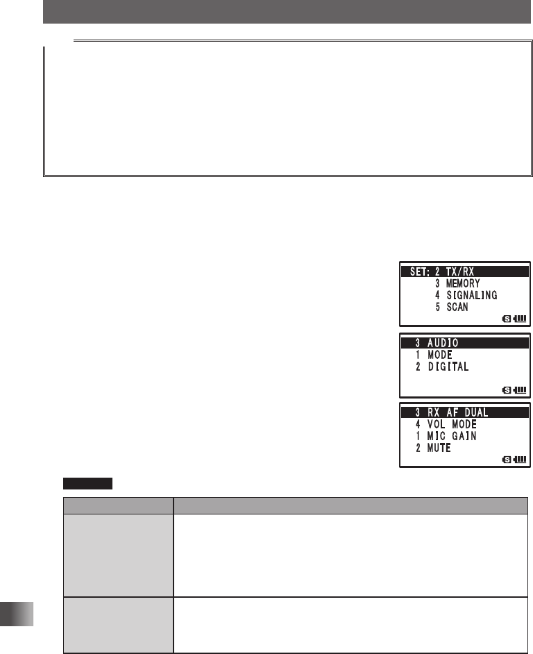
1 Press and hold M for over 1 second to enter the Set
mode.
2 Turn O to select [2 TX/RX].
3 Press H.
4 Turn O to select [3 AUDIO].
5 Press H.
6 Turn O to select [3 RX AF DUAL].
7 Press H.
8 Turn O to select reception time.
Set transmission time as well.
Transmission and reception for 1 second to 10 seconds,
HOLD (Fixed), or transmission for 1 second to 10 seconds.
Remarks Default setting: transmission and reception for 2 seconds
Display Operation
Transmission and re-
ception: 1 second to
10 seconds
While receiving radio broadcast and ham radio band frequencies (A-band
and B-band) on standby simultaneously with [AF-DUAL Reception Func-
tion], resumption of receiving radio broadcast can be set to [After loss of
receive signal] or [After transmission]. For example, if 5 seconds is selected,
radio reception resumes after 5 seconds after reception (or transmission)
ends.
Fixed While receiving radio broadcast and ham radio band frequencies (A-band
and B-band) on standby simultaneously with [AF-DUAL Reception Func-
tion], the transceiver will continue to receive a signal over that frequency
after signal detection without switching back to radio broadcast.
Application for FCC / IC
FCC ID: K6620445X20
IC: 511B-20445X20
79
Convenient Functions
Dual Reception (DW) Function
Display Operation
Transmission: 1 sec-
ond to 10 seconds
While receiving radio broadcast and ham radio band frequencies (A-band
and B-band) on standby simultaneously with [AF-DUAL Reception Func-
tion], the transceiver switches signal reception to the standby upon detect-
ing it. After the user transmits signal for response and transmission ends,
the transceiver switches signal reception back to radio broadcast after the
specified time from the end of transmission. If a signal is received before
transmitting it, [AF-DUAL Reception Function] is disabled and the transceiv-
er continually receives a signal over that frequency.
9 Press p to set the radio broadcast resumption time for
reception and Transmission, and exit the Set mode.
Using the DTMF Function
DTMF (Dual Tone Multi Frequencies) is the tone signal sent for making a call through
DTMF telephone line. The maximum of 16 digit DTMF code can be registered (up to 10
channels) for telephone numbers to make a call through the public telephone line from a
phone patch.
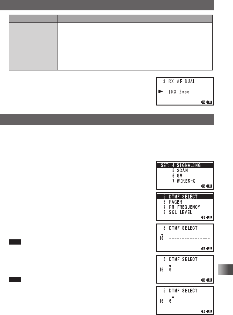
1 Press and hold M for over 1 second to enter the Set
mode.
2 Turn O to select [4 SIGNALING].
3 Press H.
4 Turn O to select [5 DTMF SELECT].
5 Press H.
6 Turn O to select a memory channel to register the DTMF
code (1 to 10).
7 Press H.
8 Input the DTMF code with O.
Tips • DTMF code can also be entered with the numeric keys.
• To delete a code, press F. When F is pressed, a code is
deleted and the cursor moves to left.
9 Press H to move the cursor.
10
Repeat steps 8 and 9 to enter the DTMF code.
Tips The maximum of 16 digits for DTMF code can be entered.
䎃 䎖 䎃 䎵 䎻 䎃 䎤 䎩 䎃 䎧 䎸䎤䎯
䎃䎃䎃䎃 䎃 䎷 䎵 䎻 䎃 䎕
䏖 䏈 䏆
䎃
䎶䎨䎷䎝䎃䎃䎕 䎃 䎷 䎻 䎒 䎵 䎻
䎃䎃䎃䎃䎃䎃䎃䎃䎖 䎃䎰䎨䎰䎲䎵䎼
䎃䎃䎃䎃䎃䎃䎃䎃䎗 䎃 䎶 䎬 䎪 䎱 䎤 䎯 䎬 䎱䎪
䎃䎃䎃䎃䎃䎃䎃䎃䎘 䎃 䎶䎦䎤䎱
䎖 䎃 䎤 䎸 䎧 䎬 䎲
䎔䎃䎰䎲䎧䎨
䎃 䎕 䎃䎧 䎬 䎪 䎬 䎷 䎤 䎯
䎖 䎃 䎵 䎻 䎃䎤 䎩 䎃䎧䎸䎤䎯
䎗䎃䎹䎲䎯䎃䎰䎲䎧䎨
䎃 䎔 䎃䎰 䎬 䎦 䎃 䎪 䎤 䎬 䎱
䎃䎕䎃䎃䎰䎸䎷䎨
Application for FCC / IC
FCC ID: K6620445X20
IC: 511B-20445X20
80
Convenient Functions
Using the DTMF Function
11
Press p to set the DTMF code and exit from the Set
mode.
Confirming the entered DTMF code by the sound
1 Press and hold M for over 1 second to enter the Set mode.
2 Turn O to select [4 APRS].
3 Press H.
4 Turn O to select [5 SCAN].
5 Press H.
6 Turn O to select the memory channel to which the DTMF
code was registered.
7 Press F to confirm the registered DTMF code by the audio
tones.
8 Press p to exit from the Set mode.
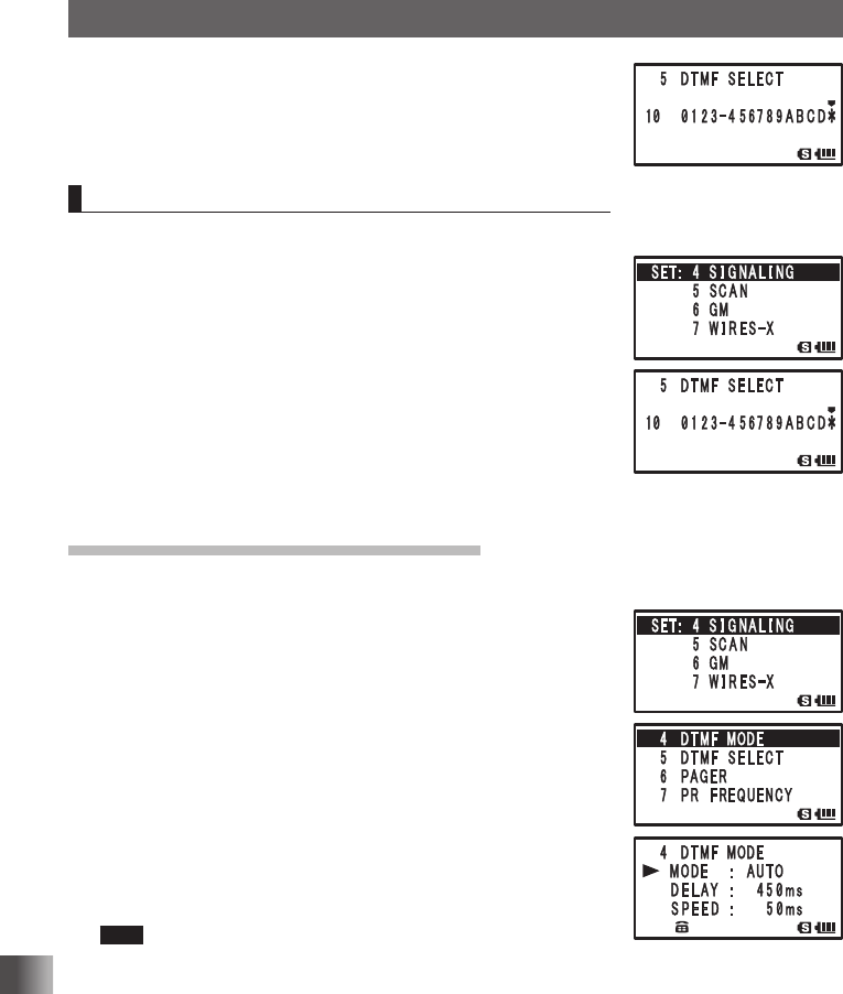
Sending the Registered DTMF Code
1 Press and hold M over 1 second to enter the Set mode.
2 Turn O to select [4 SIGNALING].
3 Press H.
4 Turn O to select [4 DTMF MODE].
5 Press H.
6 Turn O to select [MODE].
7 Press H.
8 Turn O to select [AUTO].
9 Press M.
10
Press p to set the auto dialer.
11
While pressing p key, press 1 to 0 to select the
DTMF memory channel to transmit with the numeric keys.
Tips • The registered DTMF code is transmitted.
• The transmitted DTMF tone can be heard from the speaker.
12
Release p.
Even if p is released, the DTMF tone signal will continue to be transmitted until trans-
mission of the signal is complete.
Application for FCC / IC
FCC ID: K6620445X20
IC: 511B-20445X20
81
Convenient Functions
Using the DTMF Function
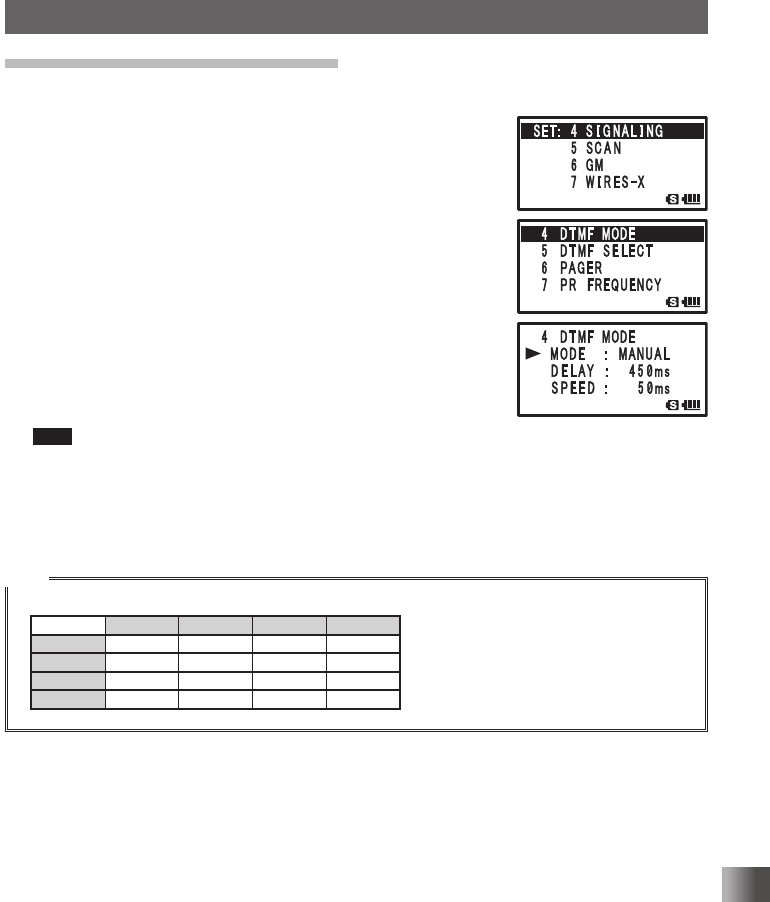
Sending a DTMF Code Manually
1 Press and hold M for over 1 second to enter the Set mode.
2 Turn O to select [4 SIGNALING].
3 Press H.
4 Turn O to select [4 DTMF MODE].
5 Press H.
6 Turn O to select [MODE].
7 Press H.
8 Turn O to select [MANUAL].
9 Press M.
10
Press p to set [MANUAL].
11
While pressing p, select the DTMF code to transmit by
pressing 1 to 0, A, B, C, , and # on the numeric
keys.
Tips • The DTMF code selected by pressing the keys is transmitted (refer to chart below).
• The transmitted DTMF tone can be heard from the speaker.
12
Release p.
Even if p is released, the DTMF tone signal will continue to be transmitted until trans-
mission of the signal is complete.
Tips
• The DTMF code is a combination of 2 frequencies.
1209Hz 1336Hz 1477Hz 1633Hz
697Hz 1 2 3 A
770Hz 4 5 6 B
852Hz 7 8 9 C
941Hz 0 # D
Application for FCC / IC
FCC ID: K6620445X20
IC: 511B-20445X20

82
Convenient Functions
Searching for signals with the signal strength graph.
Band Scope Function
While in VFO mode, the Band Scope Function is available that will graphically display
the strength of the signals on up to ±50 channels, centered on the current main band
frequency.
1 Turn O to tune in to your desired center frequency.
2 Press and hold B for over 1 second.
With the current frequency as the center, the strengths of
any signals of each of the higher and lower 16 channels are
shown on a graph.
3 Turn O to adjust the ▼ to point to any of the displayed
channels, and the signal on the indicated frequency can be
received.
4 Press B to exit the band scope function.
Tips
• You can change the number of band scope channels setting by selecting [1 DISPLAY] → [4 BAND
SCOPE] in the Set mode. The band scope channel setting can be changed to ±5 channels, ±9
channels, ±16 channels, ±24 channels, and ±50 channels, instead of ±16 channels.
• The band scope channel interval is the same as the VFO frequency step.
• When band scope is active, the numeric keys will not function.
• The audio of A/B common frequency band can be heard simultaneously while scanning.
• FULL: Continualy scans(scoops).
1Time: Scans(scoops) only once.
If the frequency is changed with O, scan will resume.
* FULL is only selected in the analog mode.
* 1Time is only selected in the digital mode.
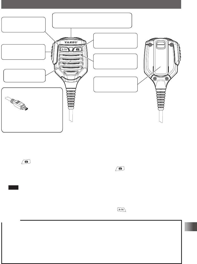
Taking picture with the optional camera mounted on speaker
microphone
Pictures can be taken by connecting the speaker microphone with optional camera (MH-
85A11U).
Captured image data can be saved to a microSD memory card placed in the transceiver.
Saved image data can be sent to another transceiver in the digital mode or using the GM
function.
In addition, image data can be transmitted to other transceivers* by pressing the
(Send Image Button] on the camera mounted on speaker microphone.
* Refer to the Yaesu homepage or catalog for the models of transceiver to which images
can be transferred.
* Only the picture just taken can be sent to another transceiver. For methods to send other
image data, refer to the GM Function instruction manual.
Application for FCC / IC
FCC ID: K6620445X20
IC: 511B-20445X20
83
Convenient Functions
Taking picture with the optional camera mounted on speaker microphone.
Send Image Button
A picture just taken can be
sent.
Lens
Aim this lrns towards the object to photograph.
Do not touch the lens with fingers or other objects.
PTT Switch
Press this button to transmit,
and release it for reception.
Speaker
Sound is emitted from here.
Shutter Button
Press this button to take a
picture.
Microphone
Speak into here with a
normal voice.
Clip
Securely clip the microphone
to belt or other objects.
Connector
Connector to connect
the speaker microphone
with camera to the
transceiver
Pay attention to the alignment of connector
when connecting the speaker microphone
with camera to the ranceiver.
Connecting it forcibly to the transceiver
may cause damage.
1 Connect the speaker microphone with camera (MH-85A11U) to the DATA terminal of
the transceiver.
2 Press P to turn the transceiver on.
3 Press .
Point the lens towards the object to shoot and press .
Make sure to have at least 50cm between the lens and the object. If the object is too
close, the picture will be out of focus, resulting in a blurred picture.
Tips • You can set the picture size (resolution) and image quality (compression rate) of the image, by
selecting [11 OPTION] → [1 USB CAMERA] in the Set mode.
• Captured images are saved to the microSD memory card installed in the transceiver.
• If your transceiver and another compatible transceiver are both in digital mode, a picture just
taken may be sent to the other transceiver by pressing .
Caution
Do not directly photograph objects with strong light, such as the sun or other bright objects. Such
operation can lead to malfunction.
If the lens or the microphone gets dirty, use a dry, soft cloth to wipe off the contaminants.
Do not place the MH-85A11U near heat emitting equipment or where it is exposed to direct sunlight.
Doing so can lead to fire or a malfunction.
Do not drop the MH-85A11U. Applying a strong shock to the MH-85A11U may result in damages or
failure.
Application for FCC / IC
FCC ID: K6620445X20
IC: 511B-20445X20
84
Communicating with a Specific Remote Station
Communicating with a Specific Remote Station
Using the Tone Squelch Function
The tone squelch opens the squelch only when a signal containing the specified frequen-
cy tone is received. Use of the digital code squelch (DCS) opens the squelch only when a
signal containing the specified DCS code is received. The tone squelch
function mutes monitoring the communications between other stations, even when listen-
ing for a call by a specific station for a long time.
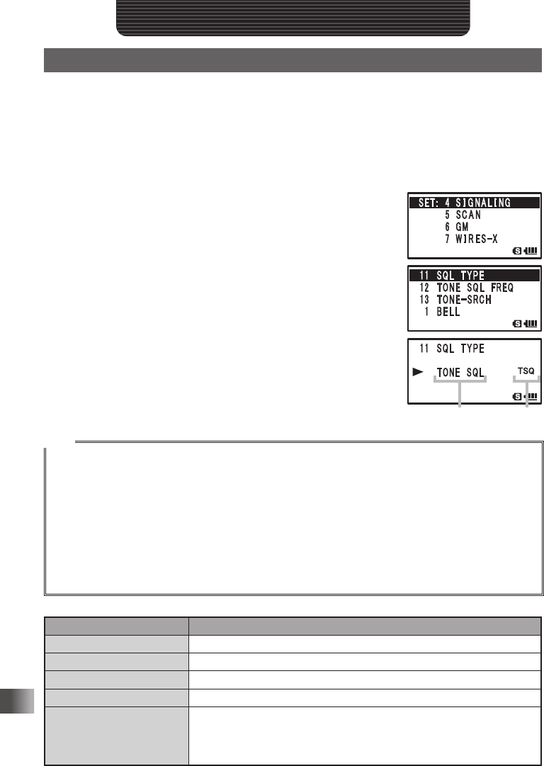
1 Press and hold M over 1 second.
2 Turn O to select [4 SIGNALING].
3 Press H.
4 Turn O to select [11 SQL TYPE].
5 Press H.
The Set mode option [11 SQL TYPE] is selected.
6 Turn O to select a squelch type.
Select a squelch type with reference to the table shown be-
low.
7 Press p to set the squelch type and exit the Set mode.
Tips
• The tone squelch and DCS setting are also active during scanning. If scanning is performed with the
tone squelch or the DCS function turned on, it stops only when a signal containing a tone of the speci-
fied frequency or a signal containing the specified DCS code is received.
• Pressing the Monitor switch allows you to hear signals that do not contain a tone or DCS code, and
signals with different tones or DCS code.
• Pressing and holding M for 1 second, and then changing the Set mode option allows you to use this
function more conveniently.
[4 SIGNALING] → [3 DCS INVERSION]: Allows you to receive the DCS code of the inverted phase.
[4 SIGNALING] → [10 SQL EXPANTION]: Allows you to specify different squelch types for transmis-
sion and reception respectively.
Display Operation
OFF Turns off the tone sending function, tone squelch function, etc.
TONE Just sends tones ([TN] appears).
TONE SQL Turns on the tone squelch function ([TSQ] appears).
DCS Turns on the digital code squelch ([DCS] appears).
REV TONE
Turns on the reverse tone ([RTN] appears). Used to monitor communi-
cations based on the squelch control system in which a tone signal is
contained when communication is not performed and the tone signal dis-
appears when communication starts.
Displays squelch
type
Displays
logo
Application for FCC / IC
FCC ID: K6620445X20
IC: 511B-20445X20
85
Communicating with a Specific Remote Station
Using the Tone Squelch Function
Display Operation
PR FREQ
Turns on the no-communication squelch function for radios ([PR] ap-
pears.). You can specify no-communication signal tone frequencies within
the range from 300 Hz to 3000 Hz in steps of 100 Hz.
PAGER (See page 90)
Turns on a new pager function ([PAG] appears). When using transceivers
with your friends, specifying personal codes (each code is composed of
two tones) allows only a specific station to be called.
D CD* Sends a DCS code only in case of transmission ([DC] appears).
TONE-DCS* Sends a tone signal in case of transmission, and waits for a DCS code in
case of reception ([T-D] appears).
D CD-TONE SQL* Sends a DCS code in case of transmission, and waits for a tone signal in
case of reception ([D-T] appears).
* Pressing and holding M over 1 second and selecting [4 SIGNALING] → [10 SQL EXPANTION] and then
[ON] will add the setting items of D CD, ONE-DCS, and D CD TONESQ to [10 SQL TYPE] of the Set mode
option [4 SIGNALING], allowing you to select different types of squelches for transmission and reception.
Selecting a Tone Frequency
You can select a tone frequency from among 50 frequencies (67.0 Hz to 254.1 Hz).
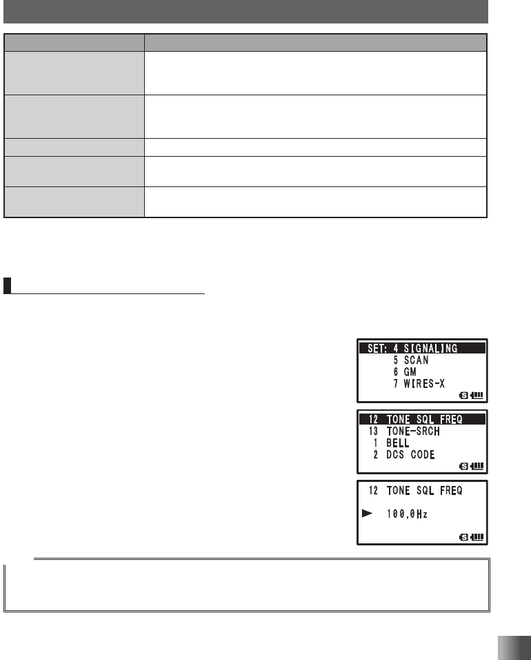
1 Specify the operating frequency.
2 Press and hold M over 1 second.
Enters the Set mode.
3 Turn O to select [4 SIGNALING].
4 Press H.
5 Turn O to select [12 TONE SQL FREQ].
6 Press H.
7 Turn O to select a tone frequency.
8 Quickly press M 3 times to save the tone frequency setting
and exit the Set mode.
Tips
• The tone frequency selected using the above-described procedure is also effective when only the
tone is sent out.
• By default, the tone frequency is set to 88.5 Hz.
Application for FCC / IC
FCC ID: K6620445X20
IC: 511B-20445X20
86
Communicating with a Specific Remote Station
Using the Tone Squelch Function
Searching for the Frequency of the
Tone Squelch Used by the Remote Station
The frequency of the tone squelch used by the remote station can be searched for and
displayed.
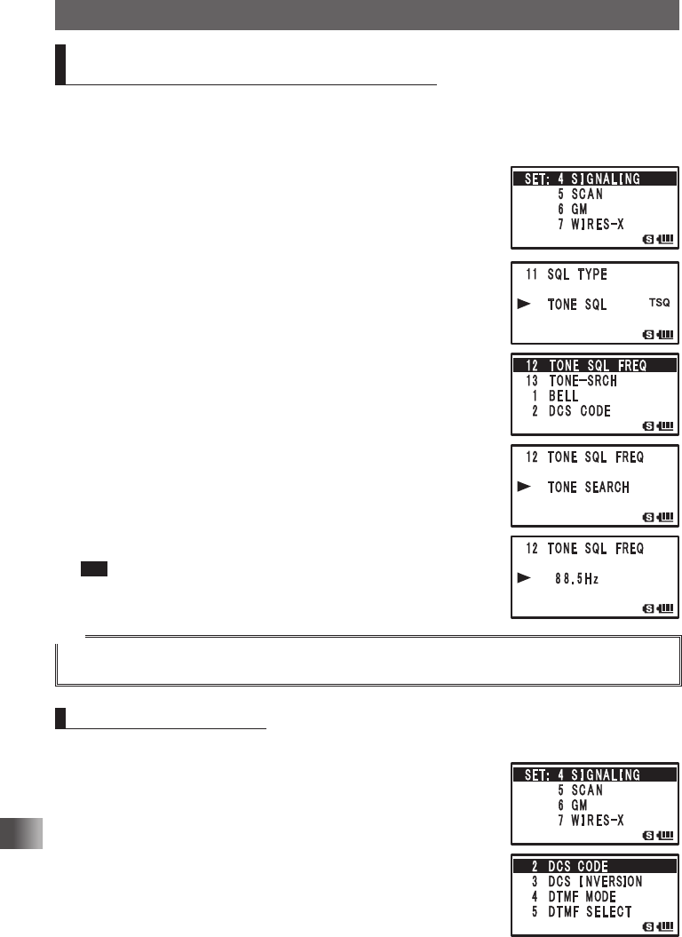
Enter the Set mode:
1 Press and hold M for over 1 second.
2 Turn O to select [4 SIGNALING].
3 Press H.
4 Turn O to select [11 SQL TYPE].
5 Press H.
6 Turn O to select [TONE SQL].
7 Press M.
8 Turn O to select [12 TONE SQL FREQ].
9 Press H.
10
Receive the signal from the remote station.
11
Press and hold B over 1 second.
[TONE SEARCH] appears.
12
Release B.
Search for the tone frequency starts.
When a corresponding tone frequency is detected, a beep
is emitted and search stops temporarily. The detected tone
frequency blinks.
Tip To set the searched tone frequency and exit from the Set mode:
Press B → a beep is emitted. → Quickly press M 3 times.
Tip
For the operation to perform when scan stops, refer to “Selecting a Reception Method When Scanning
Stops” on page 59.
Selecting a DCS Code
You can select a DCS code from among 104 DCS codes (023 to 754).
1 Specify the operating frequency.
2 Press and hold M over 1 second to enter the Set mode.
3 Turn O to select [4 SIGNALING].
4 Press H.
5 Turn O to select [2 DCS CODE].
6 Press H.
Application for FCC / IC
FCC ID: K6620445X20
IC: 511B-20445X20
87
Communicating with a Specific Remote Station
Using the Tone Squelch Function
7 Turn O to select a DCS code.
8 Quickly press M 3 times to set the DCS code and exit from
the Set mode.
Tip
By default, the DCS code is set to [023].
Searching for the Frequency of the DCS Used by the Remote Station
The DCS code used by the remote station can be searched for and displayed.
Enter the Set mode:
1 Press and hold M over 1 second.
2 Turn O to select [4 SIGNALING].
3 Press H.
4 Turn O to select [11 SQL TYPE].
5 Press H.
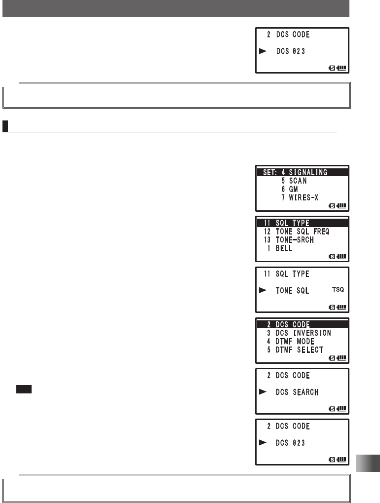
6 Turn O to select [DCS].
Sets the DCS.
7 Press M.
8 Turn O to select [2 DCS CODE].
9 Press H.
10
Receive the signal from the remote station.
11
Press and hold B over 1 second.
[DCS SEARCH] appears.
12
Release B.
Searching for the DCS code begins. When a correspond-
ing DCS code is heard, a beep is emitted and search stops
temporarily. The found DCS code blinks.
Tip To set the searched DCS code:
Press B → a beep is emitted. → Quickly press M 3 times to
set the DCS code and exit from the Set mode.
Tip
To perform the operation when scan stops, refer to “Selecting a Reception Method When Scanning
Stops” on page 59.
Application for FCC / IC
FCC ID: K6620445X20
IC: 511B-20445X20
88
Communicating with a Specific Remote Station
Using the Tone Squelch Function
Notification of Call from the Remote Station by
Vibration of the Vibrator
Set the vibrator to alert you of a call from a remote station containing a corresponding
CTCSS tone or DCS code.
Enter the Set mode:
1 Press and hold M over 1 second.
2 Turn O to select [8 CONFIG].
3 Press H.
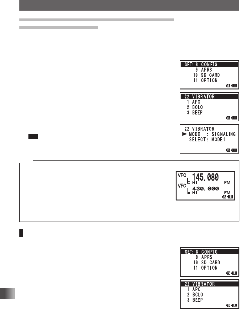
4 Turn O to select [22 VIBRATOR].
5 Press H.
6 Turn O to select [MODE].
7 Press H.
8 Turn O to select [SIGNALING].
9 Press p to set the Vibrator mode and exit the Set mode.
Tip To turn off the Vibrator function, select [OFF] in step 7.
Tips
• The vibrator function can be set for all frequency bands belonging to A-band (Main) and B-band (Sub).
• Selecting [8 CONFIG] → [22 VIBRATOR] → [MODE] and
then [BUSY] for [MODE] in the Set mode will cause the vibrator to
start vibrating when the BUSY LED lights upon reception of a signal.
• If the BUSY state is not held continuously over 5 seconds, the sus-
pended state is canceled.
If the p switch is operated to change the communication mode from
transmission to reception when the vibrator is turned ON, the vibrator function is turned off for 5 sec-
onds.
Selecting Vibrator Operation Mode
Enter the Set mode:
1 Press and hold M over 1 second.
2 Turn O to select [8 CONFIG].
3 Press H.
4 Turn O to select [22 VIBRATOR].
5 Press H.
Application for FCC / IC
FCC ID: K6620445X20
IC: 511B-20445X20
89
Communicating with a Specific Remote Station
Using the Tone Squelch Function
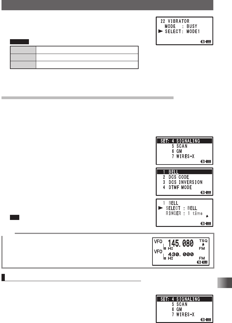
6 Turn O to select [SELECT].
7 Press H.
8 Turn O to select a vibrator operation mode.
Remark Default: MODE1
MODE1 The vibrator vibrates continuously.
MODE2 The vibrator operates at long intervals.
MODE3 The vibrator operates at short intervals.
9 Press p.
Sets the Vibrator mode and exits from the Set mode.
Notification of a Call from a Remote Station by the Bell
Set the Bell sound and the blinking b icon on the LCD, to alert you of a call from a remote
station containing a corresponding CTCSS tone or DCS code.
Enter the Set mode:
1 Press and hold M over 1 second.
2 Turn O to select [4 SIGNALING].
3 Press H.
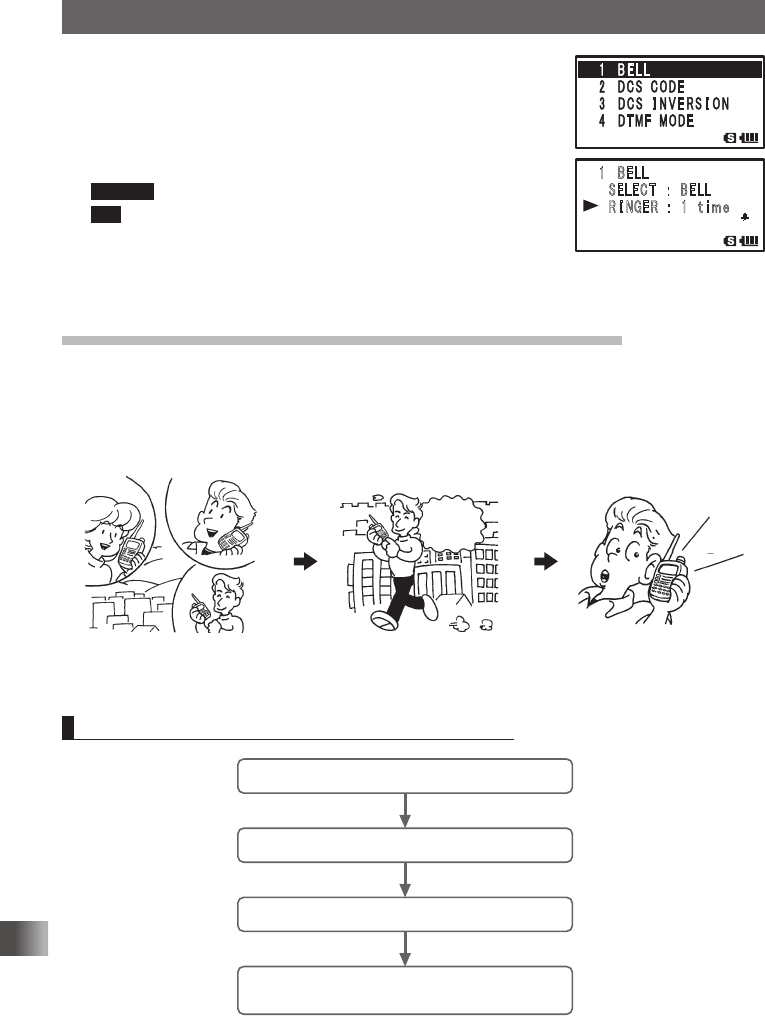
4 Turn O to select [1 BELL].
5 Press H.
6 Turn O to select [SELECT].
7 Press H.
8 Turn O to select [BELL].
When the tone squelch or DCS function is turned on, the b
icon appears.
9 Press p to set the bell function and exit Set mode.
Tip To turn off the bell function, select [OFF] in step 6.
Tips
• To use the bell function, turn on the tone squelch or DCS
function.
• The bell function cannot be used via the repeater.
• The b icon appears when the bell function is turned on.
Upon receipt of a signal from a remote station, the b icon blinks.
Changing the Number of Times the Bell Rings
Enter the Set mode:
1 Press and hold M over 1 second.
2 Turn O to select [4 SIGNALING].
3 Press H.
䎔䎃䎃䎥䎨䎯䎯
䎃 䎃 䎶䎨䎯䎨䎦䎷䎃䎃䎃䎝䎃䎃䎥䎨䎯䎯
䎃 䎃 䎵 䎬 䎱 䎪 䎨 䎵 䎃 䎝䎃䎃 䎔 䎃 䎃
䏗 䏌 䏐䏈
䎔䎃䎃䎥䎨䎯䎯
䎃 䎃 䎶䎨䎯䎨䎦䎷䎃䎃䎃䎝䎃䎃䎥䎨䎯䎯
䎃 䎃 䎵 䎬 䎱 䎪 䎨 䎵 䎃 䎝䎃䎃 䎔 䎃 䎃
䏗 䏌 䏐䏈
Application for FCC / IC
FCC ID: K6620445X20
IC: 511B-20445X20
90
Communicating with a Specific Remote Station
Using the Tone Squelch Function
4 Turn O to select [1 BELL].
5 Press H.
6 Turn O to select [RINGER].
7 Press H.
8 Turn O to select the number of times the bell rings.
Remark Default: Once
Tip You can select the number of times the bell rings from among 1 to
20 times, or continuous.
9 Press p to set the selected number of times the bell rings
and exit from the Set mode.
Calling Only a Specific Station New Pager Function
When using the transceivers with your friends, specifying personal codes (each code
composed of two CTCSS tones) allows you to call only a specific station. Even if the
called person is not near his or her transceiver, the information on the LCD indicates that
he or she has been called.
A
C
B
Mr. C sends the personal
code of Mr. B.
Three persons
A, B, and C
are using the transceiver
.
Only Mr. B is called.
I’m going
to call
Mr. B. Ring,
ring,
ring
Flow of Operation to Use the Pager Function
Set the same code as that of the remote station.
Determine a frequency.
Perform transmission/reception.
Confirm reception according to the information
on the LCD and the bell sound.
䎔䎃䎃䎥䎨䎯䎯
䎃 䎃 䎶䎨䎯䎨䎦䎷䎃䎃䎃䎝䎃䎃䎥䎨䎯䎯
䎃 䎃 䎵 䎬 䎱 䎪 䎨 䎵 䎃 䎝䎃䎃 䎔 䎃 䎃
䏗 䏌 䏐䏈
Application for FCC / IC
FCC ID: K6620445X20
IC: 511B-20445X20
91
Communicating with a Specific Remote Station
Using the Tone Squelch Function
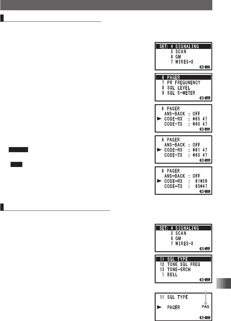
Setting the Code of Your Station
Set the personal code (your code) to be called by other stations.
Enter the Set mode:
1 Press and hold M over 1 second.
2 Turn O to select [4 SIGNALING].
3 Press H.
4 Turn O to select [6 PAGER].
5 Press H.
6 Turn O to select [CODE-RX].
7 Press H.
8 Turn O to select a code.
Select the first code from among 1 to 50.
9 Press H.
The cursor [] moves.
10
Turn O to select a code.
Select the second code from among 1 to 50.
Caution The second code must be different from the first code.
11
Press p to set your station code and exit from the Set mode.
Tips • Default: 05 47
• The first and second codes contained in your personal code
may be reversed, i.e., [47 05] from [05 47] but recognized as
the same code.
• If the same personal code (group code) is specified for all per-
sons, all persons can be called at the same time.
Turning on the New Pager Function
Enter the Set mode:
1 Press and hold M over 1 second.
2 Turn O to select [4 SIGNALING].
3 Press H.
4 Turn O to select [11 SQL TYPE].
5 Press H.
6 Turn O to select [PAGER].
7 Press p to set the new pager function and exit from the Set
mode.
You can make a call, or wait for a call from a remote station,
using the new pager function.
PAG appears.
Application for FCC / IC
FCC ID: K6620445X20
IC: 511B-20445X20
92
Communicating with a Specific Remote Station
Using the Tone Squelch Function
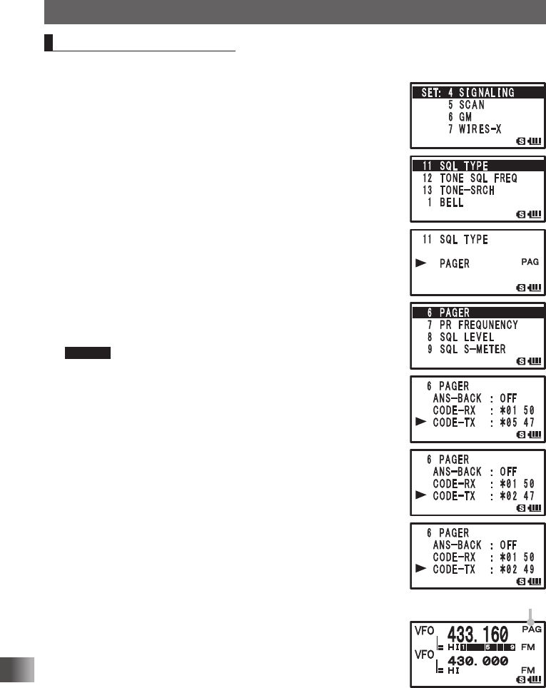
Calling a Specific Station
Enter the Set mode:
1 Press and hold M over 1 second.
2 Turn O to select [4 SIGNALING].
3 Press H.
4 Turn O to select [11 SQL TYPE].
5 Press H.
6 Turn O to select [PAGER].
Set the new pager function:
7 Press M.
8 Turn O to select [6 PAGER].
9 Press H.
10
Turn O to select [CODE-TX].
11
Press H.
12
Turn O to select the code of the remote station.
Select the first code of the remote station.
Caution Register the pager code of the remote station in advance.
13
Press H.
The cursor [] moves.
14
Turn O to select the code of the remote station.
Select the second code of the remote station.
15
Press p to set the code of the remote station and exit from
the Set mode.
16
Press p to call the remote station.
PAG appears.
Application for FCC / IC
FCC ID: K6620445X20
IC: 511B-20445X20
93
Communicating with a Specific Remote Station
Using the Tone Squelch Function
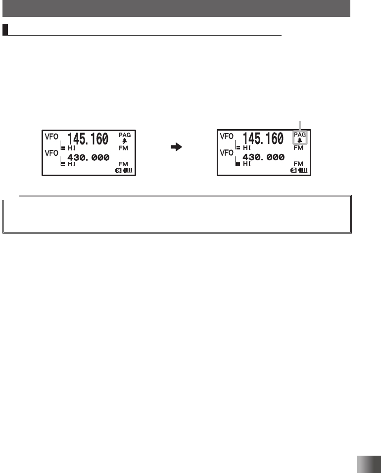
Being Called by the Remote Station (Standby Operation)
If you use the new pager function on the same frequency as the remote station, the [PAG]
icon displayed on the LCD changes to [PIN], alerting that you have been called by the
remote station. In addition, if you turn on the “bell function” (See page 89), you can con-
firm a call from the remote station by the [PAG] display, the blinking [b] icon, and the bell
sound. Also, if you turn on the “vibrator function” (See page 88), the vibrator will confirm
a call from the remote station.
Tip
Selecting [4 SIGNALING] → [9 PAGER ANS-BACK] → [ON] in the Set mode automatically places the
transceiver in the transmission mode (for about 2.5 seconds) when called by the remote party, and noti-
fies the remote party to get ready for communication.
When called
Blinks
Application for FCC / IC
FCC ID: K6620445X20
IC: 511B-20445X20
94
Functions Used As Needed
Functions Used As Needed
Set Mode
Using the Set Mode
The Set mode allows you to select various functions from a list so you can use your
transceiver more conveniently.
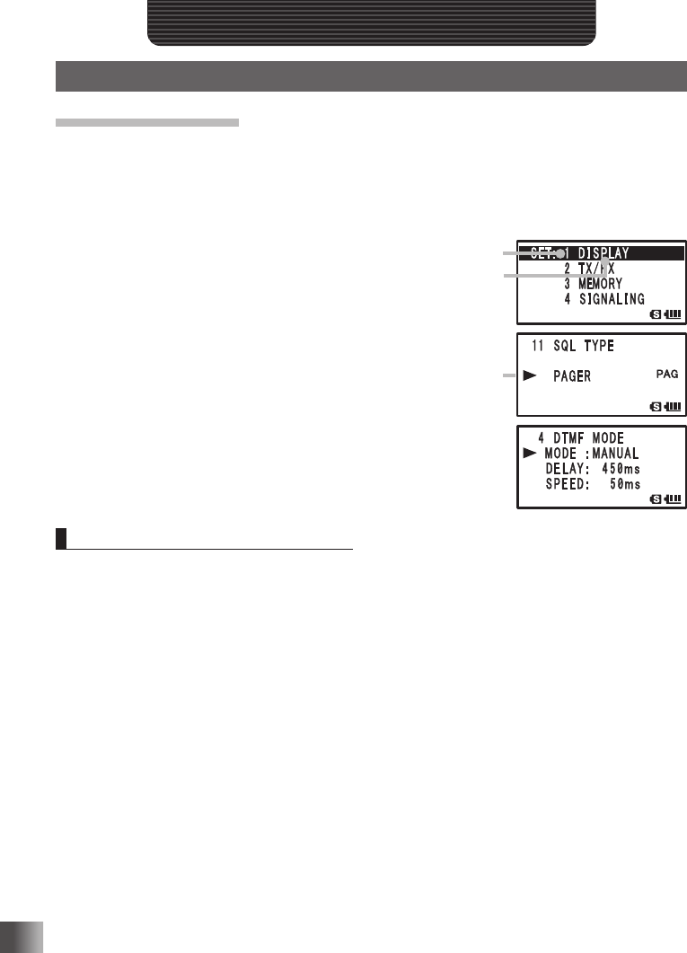
Enter the Set mode:
1 Press and hold M for over 1 second.
2 Turn O to select a Set mode option.
3 Press H.
4 Turn O to choose a setting item.
Select a setting item:
5 Press H.
[If there is no lower layer of setting items
Proceed to step 8.]
[If there is lower layer of setting items
continue with step 6.]
6 Turn O to select a setting item.
7 Press p to exit the Set mode.
Resetting the Set Mode Options
The Set mode options you have set can be restored to the defaults by following the
procedure described below. However, to restore the following setting items to the defaults,
“ALL RESET” (See page 39) is required.
2-1-2 ANTENNA ATT
2-1-4 RX MODE
3-3 MEMORY NAME
4-2 DCS CODE
4-6 PAGER (CODE-RX/CODE-TX)
4-9 SQL S-METER
4-12 TONE SQL FREQ
8-5 CLOCK TYPE
8-15 RPT SHIFT
9-7 APRS MSG TXT
9-18 DIGI PATH
9-24 MY POSITION
12 CALLSIGN
2-1-3 HALF DEVIATION
3-2 BANK NAME
3-5 MEMORY SKIP
4-3 DCS INVERSION
4-7 PR FREQUENCY
4-11 SQL TYPE
7-4 EDIT CATEGORY TAG
8-12 PASSWORD
8-16 RPT SHIFT FREQ
9-15 BEACON STATS TXT
9-23 CALLSIGN (APRS)
9-25 MY SYMBOL (4:User)
Set mode option No.
Set mode option
Setting item
Application for FCC / IC
FCC ID: K6620445X20
IC: 511B-20445X20

95
Functions Used As Needed
Set Mode
1 Press % while pressing V, and P.
Then turn the transceiver on. When a beep is heard, release the keys.
2 When [SET MODE RESET PUSH F KEY] appears, press F.
A beep is emitted.
Tip To cancel resetting, press any key other than F.
Set Mode Option List
Set mode option No./
setting Item Description of function Setting Item
(Bold letters: Default)
Reference
page
1 DISPLAY
1-1 GPS INFO Press H to open the GPS
screen.
– 103
1-2 TARGET LOCATION Set the display method for the
BACKTRACK screen that ap-
pears when using the GM Func-
tion.
COMPASS / NUMERIC 104
1-3 COMPASS Set the display method for BACK-
TRACK Compass.
HEADING UP / NORTH UP 104
1-4 BAND SCOPE Switch the Search Channel for the
BAND SCOPE operation mode.
11ch / 19ch / 33ch / 49ch / 101ch 105
1-5 LAMP Set the duration time of backlight
and keys to be lit.
OFF / 2 to 10 SEC (KEY) /
CONTINUOUS KEY 5sec
105
1-6 LANGUAGE Select Japanese or English as the
display language for Set mode
options, setting items, etc.
JAPANESE / ENGLISH 106
1-7 LCD CONTRAST Set the LCD contrast level. LEVEL 1 to LEVEL 15 Level 7 106
1-8 LCD DIMMER Set the brightness level of the
LCD backlight and keypad key
light.
LEVEL 1 to LEVEL 6 Level 6 107
1-9 OPENING
MESSAGE
Select an opening message type. NORMAL / OFF / DC /
MESSAGE / CALLSIGN
107
1-10 SENSOR INFO Display function for electrical volt-
age and temperature.
Voltage & Temperature 108
1-11 S-METER SYMBOL Select a S/PO meter symbol dis-
play type.
4 types 109
2 TX / RX
2-1 MODE
2-1-1 ANTENNA AM Select an AM radio antenna type. BAR & EXT / Bar Antenna 33
2-1-2 ANTENNA ATT Set the attenuator to ON or OFF. OFF / ON 109
2-1-3 HALF DEVIATION Set the transmission modulation
level.
OFF / ON 110
2-1-4 RX MODE Select a reception mode. AUTO / FM / AM 38
2-2 DIGITAL
2-2-1 DIGITAL MODE Select DIGITAL to switch to DIGI-
TAL mode
MODE: DIGITAL / AMS / ANALOG
DIG TX: DN / VW
AMS MODE: TX M / TX FM /
TX DN / TX VW / AUTO
111
Application for FCC / IC
FCC ID: K6620445X20
IC: 511B-20445X20

96
Functions Used As Needed
Set Mode
Set mode option No./
setting Item Description of function Setting Item
(Bold letters: Default)
Reference
page
2-2-2 SQL TYPE Select SQL Type in the DIGITAL
mode.
SQL TYPE: OFF / CODE /
BREAK
CODE: 001 to 126
113
2-2-3 DIGI POP UP Set the POP UP time. OFF BND2s / BND4s / BND6s /
BND8s / BND10s / BND20s /
BND30s / BND60s / BNDCNT
113
2-2-4 LOCATION
SERVICE
Set whether or not to display the
current location of your own sta-
tion in the digital mode.
ON / OFF
* For more details of this function, refer to
the GM Function Instruction Manual.
2-2-5 STANDBY BEEP STANDBY BEEP setting ON / OFF 114
2-2-6 DSP Ver DSP version display Version display 115
2-3 AUDIO
2-3-1 MIC GAIN Adjust the microphone gain level. LEVEL 1 to LEVEL 9 LEVEL 5 115
2-3-2 MUTE Set the muting level on the non-
operating side when a signal is
received on the operating band
side.
OFF / MUTE30% / MUTE50% /
MUTE 100%
35
2-3-3 RX AF DUAL Set the resumption time of radio
reception in the AF Dual mode.
Transmission and reception 1
second to 10 seconds, Fixed, or
transmission 1 second to 10 sec-
onds.
Transmission 2 seconds
78
2-3-4 VOL MODE Set v key. NORMAL / AUTO BACK 116
3 MEMORY
3-1 BANK LINK Set memory bank link. BANK 1 to BANK 24, BANK LINK
ON / OFF
117
3-2 BANK NAME Assign a name to a memory bank. BANK1 to BANK24 49
3-3 MEMORY NAME Enter a memory channel tag. Up to 16 characters 47
3-4 MEMORY PROTECT Allow or prohibit memory channel
registration.
OFF / ON 118
3-5 MEMORY SKIP Set memory channels or selected
memory channels to skip.
OFF / SKIP / SELECT 60
3-6 MEMORY WRITE Set the automatic increment to
display memory channel to be
registered.
NEXT / LOWER 118
4 SIGNALING
4-1 BELL Set the number of bell ring. SELECT: OFF / BELL
RINGER: 1 time to 20 times /
Continuous
89
4-2 DCS CODE Set the DCS code. DCS 023 to DCS 754 86
Application for FCC / IC
FCC ID: K6620445X20
IC: 511B-20445X20

97
Functions Used As Needed
Set Mode
Set mode option No./
setting Item Description of function Setting Item
(Bold letters: Default)
Reference
page
4-3 DCS INVERSION Select a combination of DCS in-
version codes in terms of commu-
nication direction.
RX (Reception):
-NORMAL (Homeomorphic) /
INVERT (Inversion) /
BOTH (Both Phase) /
NORMAL (Homeomorphic)
TX (Transmission):
-NORMAL (Homeomorphic) /
NORMAL (Homeomorphic)
NORMAL (Homeomorphic)
INVERT (Inversion)
119
4-4 DTMF MODE Set the transmission of DTMF
code registered to a DTMF mem-
ory channel, DTMF code trans-
mission delay time, and DTMF
code transmission speed.
MODE: MANUAL / AUTO
DELAY: 50ms / 250ms / 450ms /
750ms / 1000ms
SPEED: 50ms / 100ms
81
4-5 DTMF SELECT Set a DTMF auto dialer channel
and code (16 characters).
1 to 10 79
4-6 PAGER Turn on/off the pager answerback
function and specify a personal
code (transmission/reception).
ANS-BACK: OFF / ON
CODE-RX: 01 02 to 50 49 05 47
CODE-TX: 01 02 to 50 49 05 47
90
4-7 PR FREQUENCY Set a non-communication
squelch.
300 Hz to 3000 Hz 1600 Hz 120
4-8 SQL LEVEL Select a squelch level. Level 0 to Level 15 Level 1 121
4-9 SQL S-METER Select an S-meter squelch level. OFF / LEVEL 1 to LEVEL 9 121
4-10 SQL
EXPLANATION
Set a separate squelch type for
reception and transmission.
OFF / ON 122
4-11 SQL TYPE Select a squelch type. OFF / TONE / TONE SQL / DCS /
REV TONE / PR FREQ / PAGER
84
4-12 TONE SQL FREQ Set a tone frequency. 67.0 Hz to 254.1 Hz 100 Hz 85
4-13 TONE-SRCH Set the audio output during tone
search.
Turn the muting function on/off
and select a tone search speed.
MUTE: ON / OFF
SPEED: FAST / SLOW
123
4-14 WX ALERT Enables/Disables the Weather
Alert Feature.
OFF / ON 124
5 SCAN
5-1 DW TIME Set the priority memory channel
monitoring interval.
0.1 SEC to 10 SEC 5 SEC 124
5-2 SCAN LAMP Set the scan lamp to light or not
when scanning stops.
ON / OFF 125
5-3 SCAN RE-START Set the scanning restart time. 0.1 SEC to 10 SEC 2 SEC 125
5-4 SCAN RESUME Set the scan stop mode. SCAN:
BUSY / HOLD / 2sec to 10sec
5sec
DW:
BUSY / HOLD / 2sec to 10sec
59
5-5 SCAN WIDTH Set the scan mode. VFO: ALL / BAND
MEMORY: ALL CH / BAND
126
Application for FCC / IC
FCC ID: K6620445X20
IC: 511B-20445X20

98
Functions Used As Needed
Set Mode
Set mode option No./
setting Item Description of function Setting Item
(Bold letters: Default)
Reference
page
6 GM
6-1 LANGUAGE Select the language to use for
writing a message, etc.
JAPANESE
ENGLISH
–
6-2 DELETE GROUP Delete a registered group. – –
6-3 DELETE MEMBER Delete a registered member. – –
6-4 RADIO ID Transceiver specific number(ID)
appears. (This cannot be edited)
– –
* For more details of this function, refer to the GM Function Instruction Manual.
7 WIRES-X
7-1 LANGUAGE Select the language to use for
writing a message, etc.
JAPANESE
ENGLISH
–
7-2 RPT/WIRES FREQ Set a frequency to be used for Re-
peater/WIRES.
MANUAL / PRESET –
7-3 SERCH SETUP Set the WIRES ROOM selection
method.
HISTORY / ACTIVITY –
7-4 EDT CATEGORY
TAG
Edit a category tag. C1 to C5 –
7-5 REMOVE ROOM/
NODE
Delete a registered Category
ROOM.
C1 to C5 –
* For more details of this function, refer to the WIRES-X Function Instruction Manual.
8 CONFIG
8-1 APO Set the APO operating time. OFF / 0.5 HOUR /
1 HOUR to 12 HOURS
127
8-2 BCLO Turn on/off the busy channel lock-
out function.
OFF / ON 128
8-3 BEEP Set the beep output function and
the function of emitting a beep
when a band edge/CH1 is en-
countered.
SELECT:
KEY&SCAN / KEY / OFF
EDGE: OFF / ON
128
8-4 BUSY LED Turn on/off the BUSY LED. A BAND: ON / OFF
B BAND: ON / OFF
RADIO: ON / OFF
129
8-5 CLOCK TYPE Set the clock shift function. A / B 129
8-6 GPS LOG Set the GPS access time. OFF / 1 SEC / 2 SEC / 5 SEC /
10 SEC / 30 SEC / 60 SEC
130
8-7 HOME VFO ENABLE/DISABLE of VFO trans-
mission in Home Channel.
ENABLE / DISABLE 130
8-8 LED LIGHT Turn on/off the white LED flash-
light.
– 131
8-9 LOCK Select a lock mode. KEY&DIAL / PTT / KEY&PTT /
DIAL&PTT / ALL / KEY / DIAL
131
8-10 MONI/T-CALL Select a monitor switch or T-CALL
switch.
MONI / T-CALL *1132
8-11 TIMER Set the power ON/OFF timer. ON: 00:00 to 23:59 ON / OFF
OFF: 00:00 to 23:59 ON / OFF
132
8-12 PASSWORD Turn on/off the password function. ON / OFF [ – – – – ] 133
*1: Depends on the transceiver version.
Application for FCC / IC
FCC ID: K6620445X20
IC: 511B-20445X20

99
Functions Used As Needed
Set Mode
Set mode option No./
setting Item Description of function Setting Item
(Bold letters: Default)
Reference
page
8-13 PTT DELAY Set the PTT delay time. OFF / 20ms / 50ms / 100ms /
200ms
134
8-14 RPT ARS Turn the ARS function on/off. ON / OFF 134
8-15 RPT SHIFT Select a repeater shift direction. Differs depending on frequency 135
8-16 RPT SHIFT FREQ Select a repeater shift width. Differs depending on frequency 135
8-17 SAVE RX Set the reception save time. OFF / 0.2 SEC (1:1) to 60.0 SEC
(1:300)
136
8-18 STEP Select a channel step. AUTO / 5.0 kHz to 100 kHz 37
8-19 DATE & TIME ADJ Set up the built-in clock function. – 34
8-20 TOT Set the timeout timer. OFF / 30 SEC to 10 MIN 3.0min 136
8-21 VFO MODE Select the frequency selection
range in the VFO mode.
ALL / BAND 137
8-22 VIBRATOR Select a vibrator mode and set up
the vibrator function.
MODE:
OFF / BUSY / SIGNALING
SELECT:
MODE1 / MODE2 / MODE3
88
9 APRS
9-1 APRS AF DUAL Turn on/off the muting function
when both the APRS function and
AF dual function are active.
ON / OFF –
9-2 APRS
DESTINATION
Displaying Model Code APY01D (Cannot be edited.) –
9-3 APRS FILTER Select filter function Mic-E: ON / OFF
POSITION: ON / OFF
WEATHER: ON / OFF
OBJECT: ON / OFF
ITEM: ON / OFF
STATUS: ON / OFF
OTHER: OFF / ON
ALTNET: OFF / ON
–
9-4 APRS MODEM Set the APRS baud rate OFF / 1200bps / 9600bps –
9-5 APRS MSG FLASH Set the strobe to flash when there
is an incoming message.
MSG:
OFF / 2-4-10 (2sec interval) /
20sec / 30sec / 60sec /
CONTINUOUS /
EVERY 2s-10s (1sec interval) /
EVERY 10s-EVERY 50s
(10sec interval) / EVERY
1m-EVERY 10m (1min interval)
GRP:
OFF / 2-4-10 (2sec interval) /
20sec / 30sec / 60sec /
CONTINUOUS
BLN:
OFF / 2-4-10 (2sec interval) /
20sec / 30sec / 60sec /
CONTINUOUS
–
Application for FCC / IC
FCC ID: K6620445X20
IC: 511B-20445X20