Yaesu Musen 20445X20 AMATEUR RADIO WITH SCANNING RECEIVER User Manual 8
Yaesu Musen Co., Ltd. AMATEUR RADIO WITH SCANNING RECEIVER 8
Contents
User Manual 8
125
Functions Used As Needed
Set Mode
Turning illumination off when scanning stops
SCAN LAMP Function
You can set the backlight of LCD to turn ON or OFF when a signal is received during
scanning.
Enter the Set mode:
1 Press and hold M for over 1 second.
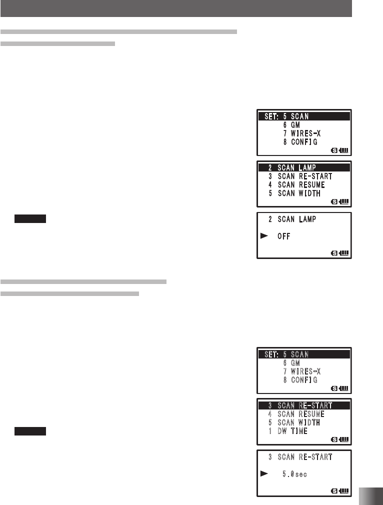
2 Turn O to select [5 SCAN].
3 Press H.
4 Turn O to select [2 SCAN LAMP].
5 Press H.
6 Turn O to select [OFF].
ON: The LCD backlight will light when a signal is received.
OFF: The LCD backlight will not light when a signal is
received.
Remark Default: ON
7 Press p to save the backlight ON or OFF setting when
scanning stops, and exit the Set mode.
Setting the time to resume scan
SCAN RE-START Function
You can set the time to resume scanning after a signal is received during scanning.
Enter the Set mode:
1 Press and hold M for over 1 second.
2 Turn O to select [5 SCAN].
3 Press H.
4 Turn O to select [3 SCAN RE-START].
5 Press H.
6 Turn O to select the time to resume scanning.
Select from 0.1 SEC to 10 SEC.
Remark Default: 2 seconds
7 Press p to set the resume scanning time, and exit the Set
mode.
䎃䎖 䎃䎶䎦䎤䎱䎃 䎃䎵 䎨
䙵
䎶 䎷 䎤 䎵 䎷
䎃䎃䎃䎃 䎃 䎘 䎑 䎓
䏖䏈䏆
䎃
䎖 䎃 䎶䎦䎤䎱䎃 䎃䎵 䎨
䙵
䎶 䎷 䎤 䎵 䎷
䎗䎃䎶䎦䎤䎱䎃 䎃䎵 䎨䎶䎸䎰䎨
䎃䎘 䎃䎶䎦䎤䎱䎃 䎃䎺 䎬 䎧䎷䎫
䎃 䎔 䎃 䎧䎺䎃 䎃䎷 䎬 䎰䎨
䎶䎨䎷䎝䎃䎃䎘䎃 䎶 䎦 䎤 䎱
䎃䎃䎃䎃䎃䎃䎃䎃䎙 䎃䎪䎰
䎃䎃䎃䎃䎃䎃䫹䎚 䎃䎺 䎬 䎵 䎨 䎶
䙵
䎻
䎃䎃䎃䎃䎃䎃䎃䎃䎛 䎃 䎦䎲䎱 䎩 䎬 䎪
䎃䎖 䎃䎶䎦䎤䎱䎃 䎃䎵 䎨
䙵
䎶 䎷 䎤 䎵 䎷
䎃䎃䎃䎃 䎃 䎘 䎑 䎓
䏖䏈䏆
䎃
䎖 䎃 䎶䎦䎤䎱䎃 䎃䎵 䎨
䙵
䎶 䎷 䎤 䎵 䎷
䎗䎃䎶䎦䎤䎱䎃 䎃䎵 䎨䎶䎸䎰䎨
䎃䎘 䎃䎶䎦䎤䎱䎃 䎃䎺 䎬 䎧䎷䎫
䎃 䎔 䎃 䎧䎺䎃 䎃䎷 䎬 䎰䎨
䎶䎨䎷䎝䎃䎃䎘䎃 䎶 䎦 䎤 䎱
䎃䎃䎃䎃䎃䎃䎃䎃䎙 䎃䎪䎰
䎃䎃䎃䎃䎃䎃䫹䎚 䎃䎺 䎬 䎵 䎨 䎶
䙵
䎻
䎃䎃䎃䎃䎃䎃䎃䎃䎛 䎃 䎦䎲䎱 䎩 䎬 䎪
Application for FCC / IC
FCC ID: K6620445X20
IC: 511B-20445X20
126
Functions Used As Needed
Set Mode
Selecting a reception method when scanning stops
Set the reception method for when scanning stops.
For more details, see “Selecting a Reception Method When Scanning Stops” on page
P. 59.
Setting the range for SCAN
You can set the frequency range for scanning with the SCAN Function.
Enter the Set mode:
1 Press and hold M for over 1 second.
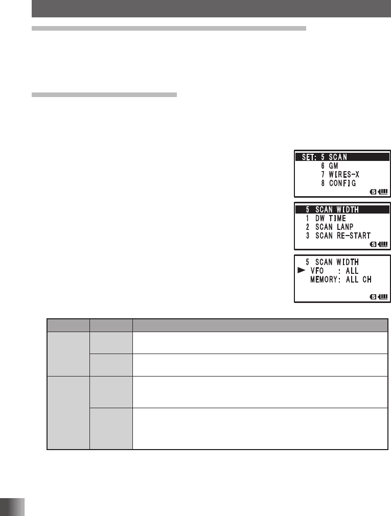
2 Turn O to select [5 SCAN].
3 Press H.
4 Turn O to select [5 SCAN WIDTH].
5 Press H.
6 Turn O to select [VFO].
7 Press H.
8 Turn O to select the range for scanning.
Specify the scanning range with reference to the next list.
9 Press M.
10
Turn O to select [MEMORY].
11 Press H.
12
Turn O to select the range for scanning.
Mode Display* Operation Status
VFO Mode
ALL Scans all bands within the range from the current frequency to 108-999
MHz.
BAND Scans the current band (see the table on the next page) starting with the
current frequency.
Memory
Mode
ALL CH
Scans all memory channels (1-900) of the currently selected memory
channel. When selected memory channels are specified, all of them are
scanned (See page 59).
BAND
Scans only the memory channels to which frequencies in the same fre-
quency band*1 are registered. When the selected memory channels are
specified, scans only the selected memory channels to which frequencies
in the same frequency band*1 are registered (See page 61).
*1 For the relationship between frequency bands and reception frequencies, see the table at the
bottom of page 28.
13
Press p to save the range for scanning, and exit the Set mode.
Application for FCC / IC
FCC ID: K6620445X20
IC: 511B-20445X20
127
Functions Used As Needed
Set Mode
Turning off the power automatically
APO Function
The transceiver may be set to turn off automatically if there is no operation for a certain
period of time.
Enter the Set mode:
1 Press and hold M for over 1 second.
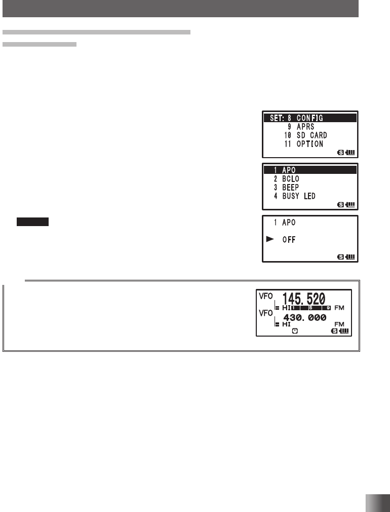
2 Turn O to select [8 CONFIG].
3 Press H.
4 Turn O to select [1 APO].
5 Press H.
6 Turn O to set the time.
Set the time for the transceiver to turn off automatically in
steps of 30 minutes.
OFF/30 MIN/1 HOUR to 12 HOURS
Remark Default: OFF
7 Press p to save the auto power-off function setting, and
exit the Set mode. The transceiver will be automatically
turned off if there is no operation for the set period of time.
Tips
• When the auto power-off function is active, the [ icon appears on
the LCD.
• Once the time for automatic power-off is set, it is retained until “OFF” is
selected in step 6 of the above-mentioned procedure. (The next time
you turn the transceiver on, if you perform no operation for the set pe-
riod of time, the transceiver will automatically turn itself off.)
Application for FCC / IC
FCC ID: K6620445X20
IC: 511B-20445X20
128
Functions Used As Needed
Set Mode
Preventing accidental transmission
Busy Channel Lockout (BCLO) Function
You can prevent accidental transmission during signal reception.
Enter the Set mode:
1 Press and hold M for over 1 second.
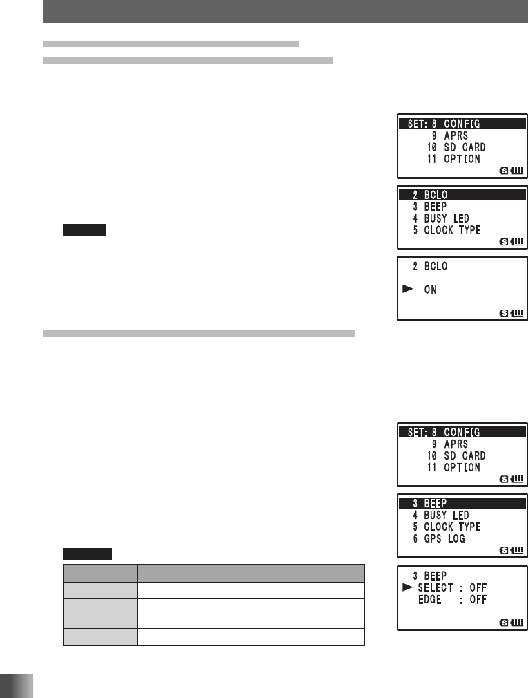
2 Turn O to select [8 CONFIG].
3 Press H.
4 Turn O to select [2 BCLO].
5 Press H.
6 Turn O to select [ON].
Remark Default: OFF
7 Press p to save the BCLO function setting, and exit the Set
mode.
Muting the key operation confirmation tone
The operation confirmation sound (beep sound) that is heard when keys are operated, or
when scanning reaches the end of a frequency band, can be turned off.
Enter the Set mode:
1 Press and hold M for over 1 second.
2 Turn O to select [8 CONFIG].
3 Press H.
4 Turn O to select [3 BEEP].
5 Press H.
6 Turn O to select [SELECT].
7 Press H.
8 Turn O to select [OFF].
Remarks Default: KEY&SCAN
Display Description
OFF Mutes the beep.
KEY&SCAN Emits a beep when a key is operated or scan-
ning stops.
KEY Emits a beep when a key is pressed.
9 Press M.
10
Turn O to select [EDGE].
11 Press H.
12
Turn O to select [OFF].
13
Press p to exit from the Set mode.
Application for FCC / IC
FCC ID: K6620445X20
IC: 511B-20445X20
129
Functions Used As Needed
Set Mode
Turning off the BUSY Indicator
When you listen to the radio continuously or when the remaining battery level has become
low, you can turn off the BUSY indicator to save battery power consumption.
Enter the Set mode:
1 Press and hold M for over 1 second.
2 Turn O to select [8 CONFIG].
3 Press H.
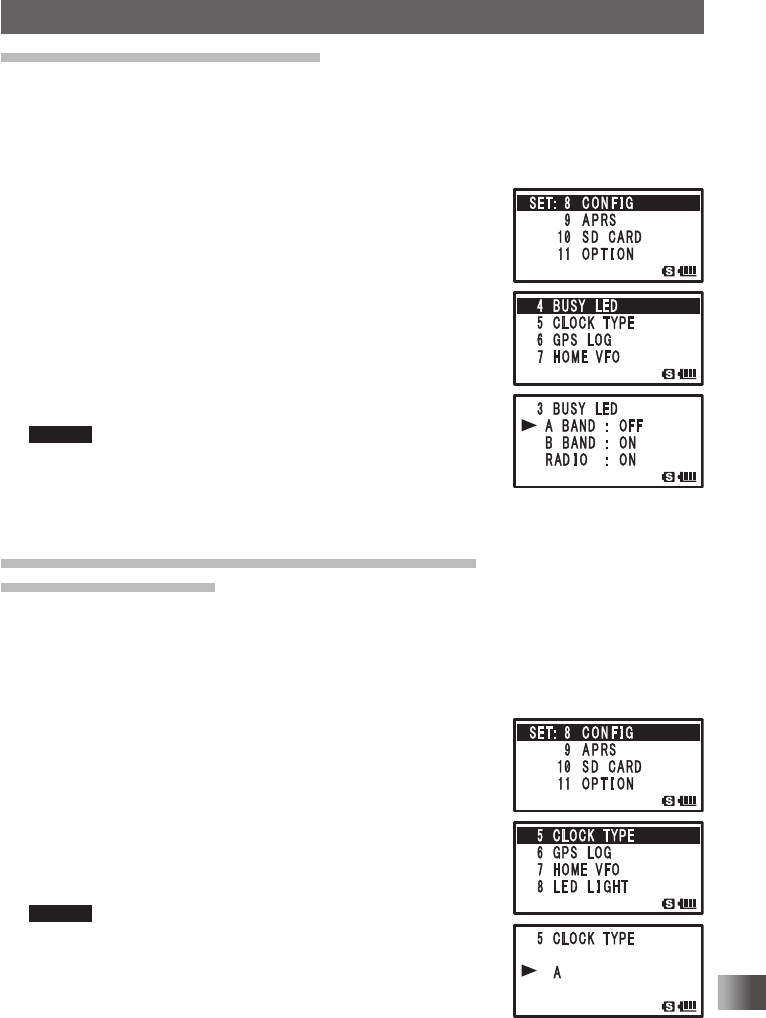
4 Turn O to select [4 BUSY LED].
5 Press H.
6 Turn O to select a band.
Select a band from among [A BAND], [B BAND], and
[RADIO].
7 Press H.
8 Turn O to select [OFF].
Remark Default: ON
9 Press p.
The BUSY indicator is turned off, and exits from the Set
mode.
Setting the clock shift for the micro computer
Clock Type Function
The micro computer Clock Shift function may be set to reduce internal high frequency
spurious interference signals. Select [A] for normal use.
Enter the Set mode:
1 Press and hold M for over 1 second.
2 Turn O to select [8 CONFIG].
3 Press H.
4 Turn O to select [5 CLOCK TYPE].
5 Press H.
6 Turn O to select a clock type.
A: The Clock Shift function is automatically turned on or off.
B: The Clock Shift function is continually active.
Remark Default: A
7 Press p to save the Clock Type setting, and exit the Set
mode.
Application for FCC / IC
FCC ID: K6620445X20
IC: 511B-20445X20
130
Functions Used As Needed
Set Mode
Setting interval to save GPS position information
Set the interval at which the GPS information of your current position is saved to the
microSD memory card.
Enter the Set mode:
1 Press and hold M for over 1 second.
2 Turn O to select [8 CONFIG].
3 Press H.
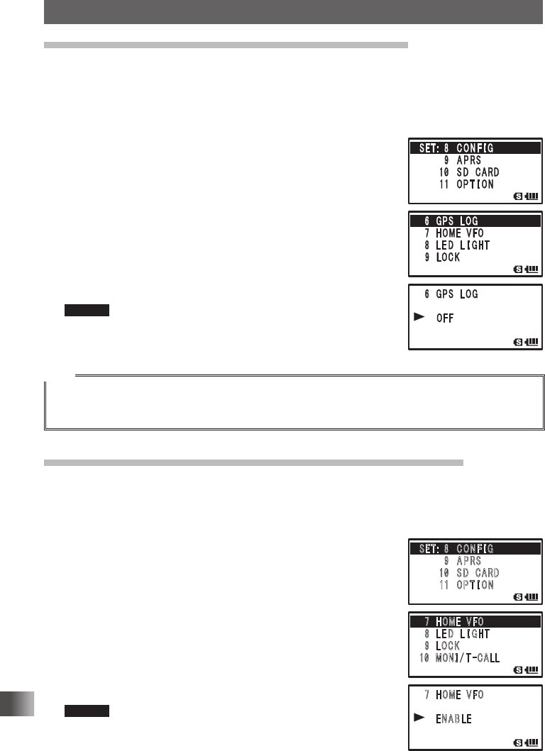
4 Turn O to select [6 GPS LOG].
5 Press H.
6 Turn O to select an interval to save GPS position
information.
OFF / 1 SEC / 2 SEC / 5 SEC /10 SEC / 30 SEC / 60 SEC
Information is not recorded to the microSD memory card if
OFF is selected.
Remark Default: OFF
7 Press p to save the GPS information saving interval
setting, and exit the Set mode.
Tips
• Data saved to the microSD memory card is saved in xxx.LOG format.
• Saved data can be viewed with PC applications*.
* PC applications are not supported by our company.
Permitting Transfer of Home Channel Frequency to VFO
You can use the set operation to transfer home channel frequency information to the VFO.
Enter the Set mode:
1 Press and hold M for over 1 second.
2 Turn O to select [8 CONFIG].
3 Press H.
4 Turn O to select [7 HOME VFO].
5 Press H.
6 Turn O to select Unlock or Lock.
ENABLE: Turning O in home channel transfers the home
channel frequency to VFO.
DISABLE: The home channel frequency cannot be
transferred.
Remark Default: ENABLE
7 Press p to save the frequency transfer ENABLE/DISABLE/
Unlock setting, and exit the Set mode.
䎃䎚䎃䎃䎫䎲䎰䎨䎃䎃䎹䎩䎲
䎃䎛䎃䎃䎯 䎨 䎧 䎃䎃 䎯 䎬 䎪䎫䎷
䎃 䎜 䫹 䎯 䎲 䎦 䎮
䎔䎓䫹 䎰 䎲䎱 䎬 䎒 䎷
䙵
䎦䎤䎯䎯
䎃䎚䎃䎃䎫䎲䎰䎨䎃䎃䎹䎩䎲
䎃 䎃䎃
䎃 䎃䎃 䎃䎨䎱䎤䎥䎯䎨
䎃䎃䎃
䎶䎨䎷䎝䎃 䎃䎛 䫹 䎦 䎲 䎱 䎩 䎬 䎪
䎃䎃䎃䎃䎃䎃䎃䎃䎜 䫹 䎤 䎳 䎵䎶
䎃䎃䎃䎃䎃䎃䫹䎔䎓䫹 䎶 䎧䎃䎃䎦䎤䎵䎧
䎃䎃䎃䎃䎃 䎃䎔䎔䫹 䎲 䎳 䎷 䎬 䎲 䎱
Application for FCC / IC
FCC ID: K6620445X20
IC: 511B-20445X20
131
Functions Used As Needed
Set Mode
Using the White LED as a Flashlight
The white LED may be used as a flashlight.
Enter the Set mode:
1 Press and hold M for over 1 second.
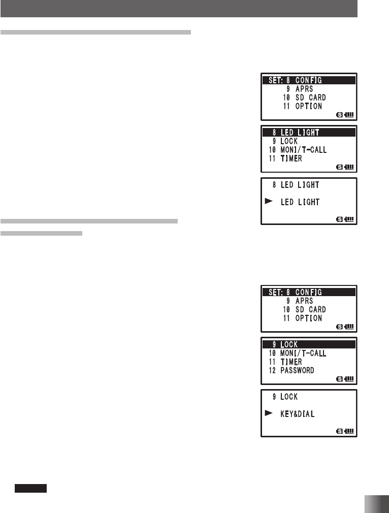
2 Turn O to select [8 CONFIG].
3 Press H.
4 Turn O to select [8 LED LIGT].
5 Press H.
The white LED lights as a flashlight.
6 Press M.
The LED goes out.
7 Press p to exit from the Set mode.
Setting the conditions for locking
LOCK Function
Conditions for activating Lock Function, such as keys, O, and p, can be set.
Enter the Set mode:
1 Press and hold M for over 1 second.
2 Turn O to select [8 CONFIG].
3 Press H.
4 Turn O to select [9 LOCK].
5 Press H.
6 Turn O to select the keys and switches to lock.
KEY & DIAL: Locks the keys and O on the front of the
transceiver.
PTT: Locks p.
KEY & PTT: Locks the keys and p on the front of the
transceiver.
DIAL & PTT: Locks O and p.
ALL: Locks the keys, O, and p on the front of the
transceiver.
KEY: Locks the keys on the front of the transceiver.
DIAL: Locks O.
Remark Default: KEY&DIAL
7 Press p.
The keys and switches to lock are set, and exits from the Set mode.
Application for FCC / IC
FCC ID: K6620445X20
IC: 511B-20445X20
132
Functions Used As Needed
Set Mode
Setting the operation of
The function for when T is pressed can be set.
Enter the Set mode:
1 Press and hold M for over 1 second.
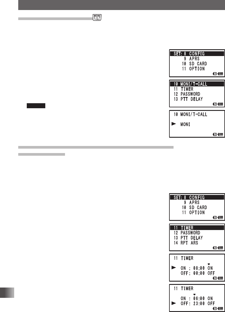
2 Turn O to select [8 CONFIG].
3 Press H.
4 Turn O to select [10 MONI/T-CALL].
5 Press H.
6 Turn O to select the function.
MONI: Pressing T monitors frequency.
T-CALL: Pressing T functions as tone call.
Remark Default: Depends on the transceiver version.
7 Press H.
The function for T is set.
8 Press p to save the setting and exit the Set mode.
Turning on/off the transceiver at the specified time
Timer Function
You can turn the transceiver to turn on/off at the set time. Before using this function, adjust
the clock. See “Setting clock time” on page 34.
Enter the Set mode:
1 Press and hold M over 1 second.
2 Turn O to select [8 CONFIG].
3 Press H.
4 Turn O to select [11 TIMER].
5 Press H.
6 Turn O to select [ON] or [OFF].
ON: Turns on the transceiver at the specified time.
OFF: Turns off the transceiver at the specified time.
7 Press H.
8 Turn O to specify hours.
9 Press H.
10
Turn O to specify minutes.
11 Press H.
12
Turn O to switch between ON/OFF of the timer.
13
Press M.
The timer function is turned on.
14
Press p to exit from the Set mode.
Application for FCC / IC
FCC ID: K6620445X20
IC: 511B-20445X20
133
Functions Used As Needed
Set Mode
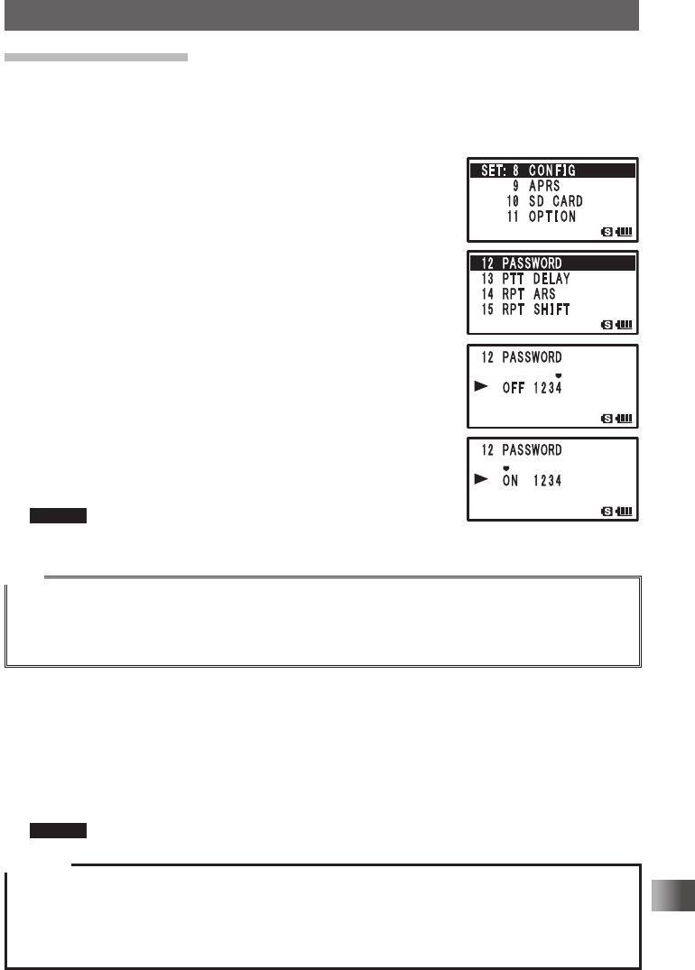
Password Function
You can enter a 4-character password to prevent a third party from using your transceiver
without permission. Once a password is entered, the transceiver cannot be turned on until
the valid password is entered.
Enter the Set mode:
1 Press and hold M for over 1 second.
2 Turn O to select [8 CONFIG].
3 Press H.
4 Turn O to select [12 PASSWORD].
5 Press H.
6 Press H.
7 Turn O to enter the first character of the password.
Enter the first character (0-9. A to D, , and #) of the
password.
8 Press H.
The cursor moves to the next character position.
9 Repeat steps 7 and 8 to enter the remaining three characters.
10
Press H.
11 Turn O to select [ON].
Remark Default: OFF
12
Press p to save the password setting, and exit the Set mode.
Tips
• To cancel the password function, execute the above-mentioned steps 1 to 5, select “OFF” with O,
and then press p over 1 second.
• Keypad keys cannot be used to enter the password.
• When the on-timer function is active, the password function is ineffective.
Turning on the transceiver using a password
1 Press and hold P for over 1 second.
The password entry screen appears.
2 Enter the password using keypad keys.
Enter the registered 4-character password.
When the valid password is entered, the frequency display screen appears.
Remark When an invalid password is entered, the transceiver is turned off automatically.
Caution
If you’ve forget the registered password, carrying out all resetting allows you to turn on the transceiver
without entering the password.
It should be noted that performing all resetting resets (initializes) all information such as the information
registered to memory channels and various setting values.
It is recommended that the password be written down on paper.
Application for FCC / IC
FCC ID: K6620445X20
IC: 511B-20445X20
134
Functions Used As Needed
Set Mode
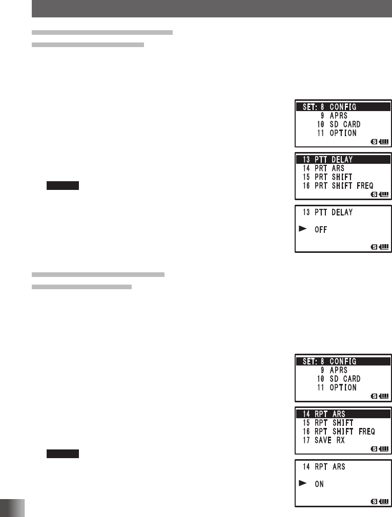
Setting the PTT delay time
PTT DELAY Function
You can set the time for actual transmission to start after p is pressed.
Enter the Set mode:
1 Press and hold M for over 1 second.
2 Turn O to select [8 CONFIG].
3 Press H.
4 Turn O to select [13 PTT DELAY].
5 Press H.
6 Turn O to select the time.
OFF/20ms/50ms/100ms/200ms
Remark Default: OFF
7 Press p to save the PTT delay time setting, and exit the
Set mode.
Setting the ARS function
RPT ARS Function
You can set the operation of ARS (Tuning in to the repeater frequency automatically
enables the repeater).
Enter the Set mode:
1 Press and hold M for over 1 second.
2 Turn O to select [8 CONFIG].
3 Press H.
4 Turn O to select [14 RPT ARS].
5 Press H.
6 Turn O to select ON/OFF.
ON: ARS is functional.
OFF: ARS is not functional.
Remark Default: ON
7 Press p to save the ARS function ON/OFF setting, and exit
the Set mode.
Application for FCC / IC
FCC ID: K6620445X20
IC: 511B-20445X20
135
Functions Used As Needed
Set Mode
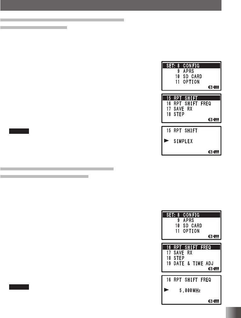
Setting the direction for repeater shift
RPT SHIFT Function
You can set the direction of repeater shift.
Enter the Set mode:
1 Press and hold M for over 1 second.
2 Turn O to select [8 CONFIG].
3 Press H.
4 Turn O to select [15 RPT SHIFT].
5 Press H.
6 Turn O to select the shift direction.
SIMPLEX: Does not shift.
–RPT: Shifts toward lower frequencies.
+RPT: Shifts toward higher frequencies.
Remark Default setting differs depending frequency
7 Press p to save the repeater shift direction setting, and exit
the Set mode.
Setting the range for repeater shift
RPT SHIFT FREQ Function
You can set the repeater shift range.
Enter the Set mode:
1 Press and hold M for over 1 second.
2 Turn O to select [8 CONFIG].
3 Press H.
4 Turn O to select [16 RPT SHIFT FREQ].
5 Press H.
6 Turn O to select shift range.
The range can be set in steps of 50 kHz between 0.0000
MHz and 150.000 MHz.
Pressing F and then turning O allows you to set
frequencies in steps of 1 MHz.
Remark Default setting differs depending frequency
7 Press p to save the repeater shift range setting, and exit
the Set mode.
Application for FCC / IC
FCC ID: K6620445X20
IC: 511B-20445X20
136
Functions Used As Needed
Set Mode
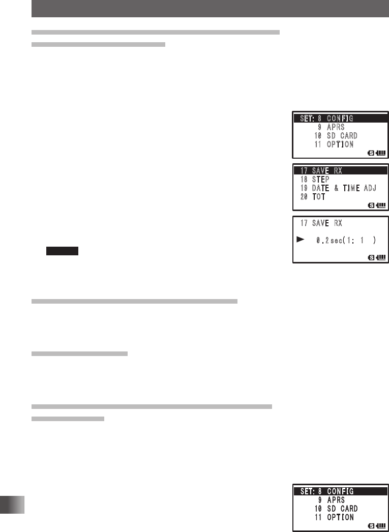
Disabling reception while no signal is received
Reception Save Function
To reduce power consumption, the reception function can be turned off when not receiving
a signal.
Enter the Set mode:
1 Press and hold M for over 1 second.
2 Turn O to select [8 CONFIG].
3 Press H.
4 Turn O to select [17 SAVE RX].
5 Press H.
6 Turn O to select the time.
Select the time for the reception to be turned off automatically.
0.2 SEC (1:1) to 1.0 SEC (1:5) (Step: 0.1 sec)
to 1.0 SEC (1:5) to 10 SEC (1:50) (Step: 0.5 sec)
to 1.0 sec (1:50) to 60 sec (1:300 sec) step 5 sec
OFF
Remark Default: 0.2 sec (1:1)
7 Press p to save the Reception Save function setting, and
exit the Set mode.
Changing the frequency step manually
Frequency step can be set so that it can be changed manually.
For more details, see “Changing the Frequency Step Manually” on page 37.
Setting clock time
Set the time for the internal clock of this transceiver.
For details, see “Setting clock time” on page 34.
Restricting the continuous transmission time
TOT Function
Set the transceiver to automatically return to the receive mode after transmitting
continuously for a certain period of time. Accidental transmission of unnecessary signals,
and unwanted battery power consumption can be prevented (time-out timer function).
Enter the Set mode:
1 Press and hold M for over 1 second.
2 Turn O to select [8 CONFIG].
3 Press H.
䎔䎚䎃 䎃䎶䎤䎹䎨䎃䎃䎵䎻
䎔䎛䎃 䎃䎶 䎷 䎨 䎳
䎔䎜䫹䎧䎤䎷 䎨 䎃䎃 䎉䎃 䎃 䎷 䎬 䎰 䎨 䎃 䎃䎤䎧䎭
䎕䎓䫹䎷䎲䎷
䎔䎚䎃 䎃䎶䎤䎹䎨䎃䎃䎵䎻
䎃 䎃䎃
䎃 䎃䎃 䎃䎃䎃䎓 䎑 䎕
䏖䏈䏆
䎋 䎔 䎝 䎃䎔䎃 䎃 䎃䎌
䎃
䎶䎨䎷䎝䎃 䎃䎛 䫹 䎦 䎲 䎱 䎩 䎬 䎪
䎃䎃䎃䎃䎃䎃䎃䎃䎜 䫹 䎤 䎳 䎵䎶
䎃䎃䎃䎃䎃䎃䫹䎔䎓䫹 䎶 䎧䎃䎃䎦䎤䎵䎧
䎃䎃䎃䎃䎃 䎃䎔䎔䫹 䎲 䎳 䎷 䎬 䎲 䎱
Application for FCC / IC
FCC ID: K6620445X20
IC: 511B-20445X20
137
Functions Used As Needed
Set Mode
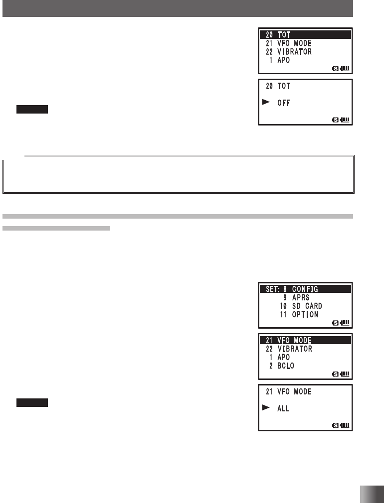
4 Turn O to select [20 TOT].
5 Press H.
6 Turn O to select the time.
Set the time for the transceiver to automatically return to the
reception state in steps of 30 seconds.
OFF/30 SEC to 10 MIN
Remark Default: OFF
7 Press p to save the TOT function setting, and exit the Set
mode.
Tips
• When the time-out timer function is active, a beep is emitted when it comes near the set time. About
10 seconds later, the transceiver returns to the reception state.
• Once the time is set, it is retained until “OFF” is selected in step 6 of the above-mentioned procedure.
Setting the frequency selection range for operation in the VFO mode
VFO MODE Function
You can set the frequency selection range for operating in the VFO mode.
Enter the Set mode:
1 Press and hold M over 1 second.
2 Turn O to select [8 CONFIG].
3 Press H.
4 Turn O to select [21 VFO MODE].
5 Press H.
6 Turn O to select a frequency range.
ALL: Switches to the next band when the end of a band is
reached.
BAND: Moves to the other end of the band when the end of
that band is reached.
Remark Default: BAND
7 Press p to save the frequency selection range setting, and
exit the Set mode.
Application for FCC / IC
FCC ID: K6620445X20
IC: 511B-20445X20
138
Functions Used As Needed
Set Mode
Notification of a call from a remote station by vibration
The vibrator function may be set to notify you of a call from a remote station.
For details, see “Notification of Call from the Remote Station by Vibration of the Vibrator”
on page 88.
Saving/ Loading data to/from microSD memory card
Settings information can be saved to a microSD memory card, also the saved information
can be loaded to the transceiver.
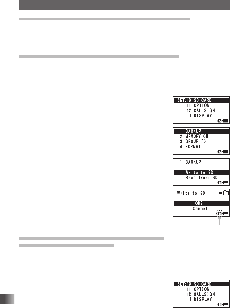
Enter the Set mode:
1 Press and hold M over 1 second.
2 Turn O to select [10 SD CARD].
3 Press H.
4 Turn O to select [1 BACKUP].
5 Press H.
6 Turn O to select [Write to SD] or [Read from SD].
Write to SD: Saves the setting information of your transceiver
to the microSD memory card.
Read from SD: Loads the setting information to your
transceiver from the microSD memory card.
Cancel: Stops save or load.
7 Press H.
[OK?] appears on the LCD.
8 Press H.
The write or read is performed and [Completed] appears
when finished.
9 Press p to exit from the Set mode.
Saving/ Loading memory channel information
to/from microSD memory card
Memory channel setting information can be saved to a microSD memory card, or saved
information can be loaded to this transceiver.
Enter the Set mode:
1 Press and hold M for over 1 second.
2 Turn O to select [10 SD CARD].
3 Press H.
Blinks when writing
Blinks when writing
Application for FCC / IC
FCC ID: K6620445X20
IC: 511B-20445X20
139
Functions Used As Needed
Set Mode
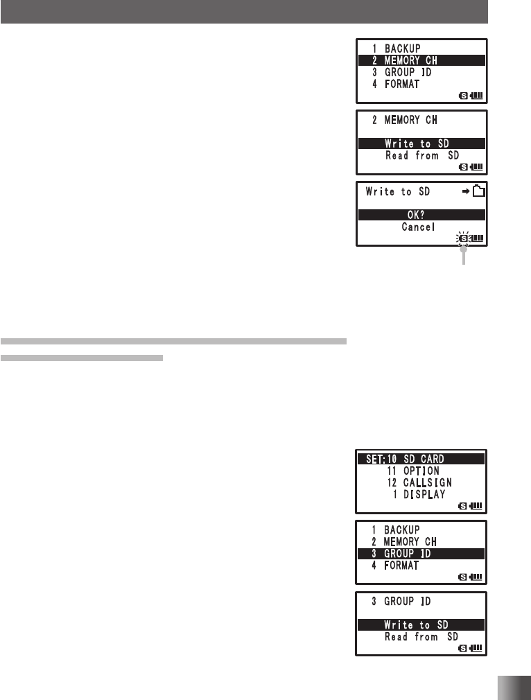
4 Turn O to select [2 MEMORY CH].
5 Press H.
6 Turn O to select [Write to SD] or [Read from SD].
Write to SD: A beep is heard and [Completed] appears when
writing to SD finished.
Read from SD: A beep is heard when loading from SD finished
and the transceiver restarts with the settings
read from the microSD memory card. (The
operation in step 9 is not required.)
Cancel: Stops save or load.
7 Press H.
[OK?] appears on the LCD.
8 Press H.
The write or read is performed and [Completed] appears
when finished.
9 Press p to exit from the Set mode.
Saving/ Loading GROUP ID information to/from
microSD memory card
Group ID setting information can be saved to a microSD memory card, or saved informa-
tion can be loaded to this transceiver.
Enter the Set mode:
1 Press and hold M for over 1 second.
2 Turn O to select [10 SD CARD].
3 Press H.
4 Turn O to select [3 GROUP ID].
5 Press H.
6 Turn O to select [Write to SD] or [Read from SD].
Write to SD: Saves the Group ID information to your
transceiver to the microSD memory card.
Read from SD: Loads the Group ID information to your
transceiver from the microSD memory card.
Cancel: Stops save or load.
7 Press H.
[OK?] appears on the LCD.
Blinks when writing
Blinks when writing
Application for FCC / IC
FCC ID: K6620445X20
IC: 511B-20445X20

140
Functions Used As Needed
Set Mode
8 Press H.
Write to SD: A beep is heard and [Completed] appears when
writing to SD finished.
Read from SD: A beep is heard when loading from SD
finished and the transceiver restarts with
the settings read from the microSD memory
card. (The operation in step 9 is not required.)
9 Press p to exit from the Set mode.
Formatting a microSD memory card
Format a new microSD.
For more details, see “Formatting a microSD memory card” on page 24.
Setting the optional microphone with camera for use
Image size and quality can be set for the optional microphone with camera (MH-85A11U).
Enter the Set mode:
1 Press and hold M for over 1 second.
2 Turn O to select [11 OPTION].
3 Press H.
4 Turn O to select [1 USB CAMERA].
5 Press H.
6 Turn O to select [SIZE].
7 Press H.
8 Turn O to select an image size.
320×240
160×120
9 Press H.
10
Turn O to select [QUALITY].
11 Press H.
12
Turn O to select an image quality.
LOW: Low image quality
NORMAL: Intermediate image quality
HIGH: High image quality
13
Press p to exit from the Set mode.
Caution
If image size is set to large or image quality is set to high, the data transmission time becomes longer.
The transmission time varies depending on the content of an image.
Blinks when writing
Application for FCC / IC
FCC ID: K6620445X20
IC: 511B-20445X20
141
Functions Used As Needed
Set Mode
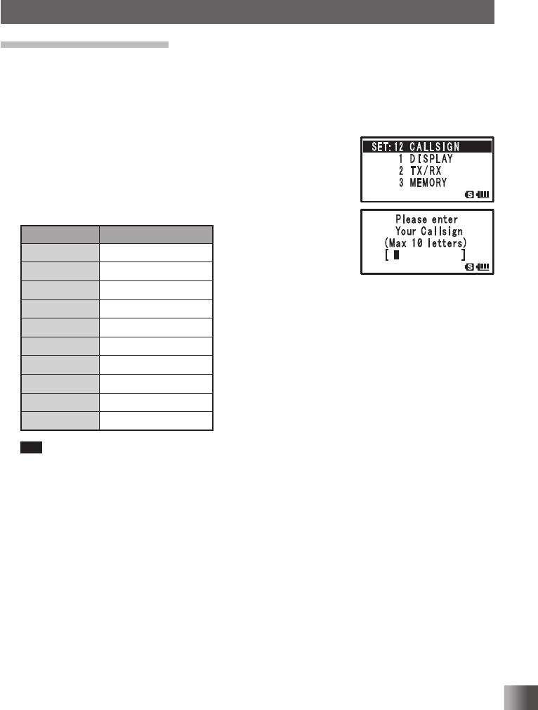
Registering CALLSIGN
The CALLSIGN used in the digital mode can be registered with up to 10 alphanumeric
characters.
Enter the Set mode:
1 Press and hold M for over 1 second.
2 Turn O to select [12 CALLSIGN].
3 Press H.
4 Enter the characters using keypad keys.
Enter a callsign using keypad keys with reference to the
following table.
Numeric key A, 0 (Alphanumeric)
11
2ABC2
3DEF3
4GHI4
5JKL5
6MNO6
7PQRS7
8TUV8
9WXYZ9
00
Tip • Pressing H moves the cursor to the right.
• Press the % to move the corsor back to the left.
• Press the F to delete the letter or number at the current cursor position.
5 Press H.
The cursor moves.
6 Repeat steps 4 and 5 to enter the CALLSIGN.
7 Press p to save the CALLSIGN setting and exit the Set mode.
Application for FCC / IC
FCC ID: K6620445X20
IC: 511B-20445X20
142
Functions Used As Needed
Set Mode
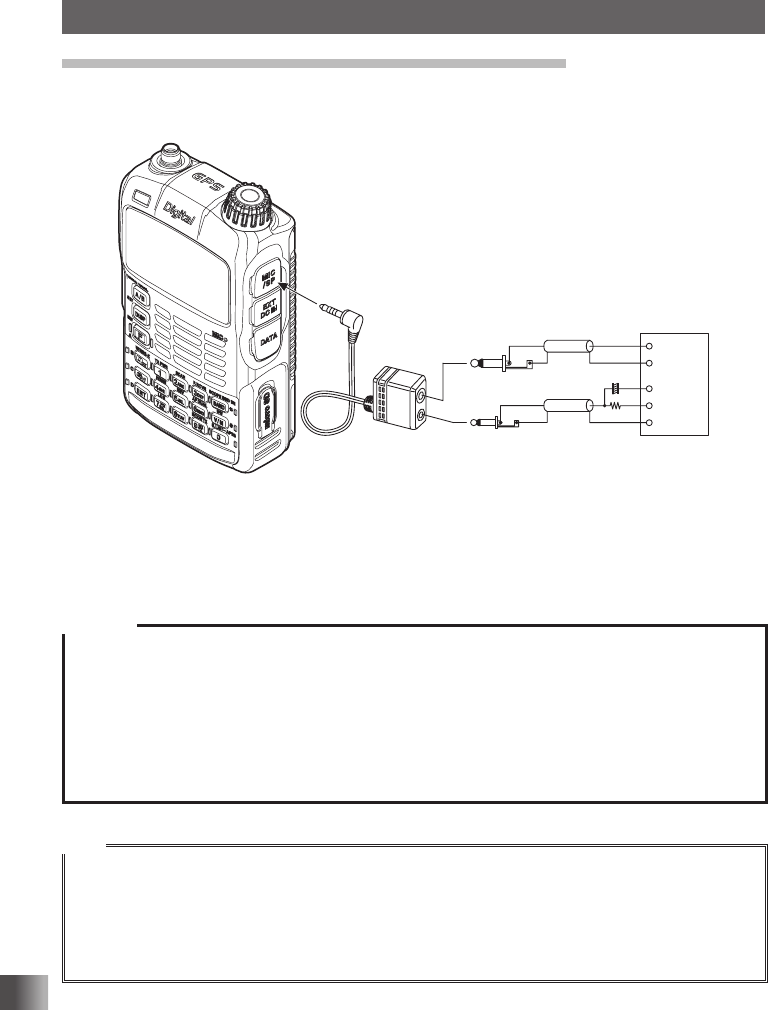
Using the transceiver for packet communication
You can perform packet communication with your transceiver by connecting TNC
(Terminal Node Controller) using an optional connection cable (CT-44).
TNC
SP
GND
GND
2 kΩ
10 F
Ǵ
MIC
MIC
EAR
PTT
After TNC is connected, set the level of output to TNC by adjusting the sound volume level
of your transceiver.
Also adjust the level of input to your transceiver using the output level adjustment volume
on the TNC (Input level cannot be adjusted on your transceiver)
Caution
When sending a vast volume of data, the transmission takes a longer time and the transceiver may be
overheated.
If the transmission is continued for a long time, the overheat prevention circuit will operate and the
transmission power decreases. If the transmission is continued further, the transmission will be au-
tomatically stopped to prevent the transceiver from overheating and consequently malfunctioning.
The transceiver will return to the receive mode.
When the transceiver returns to the receive mode after the overheat prevention circuit has operated,
turn the transceiver off, or keep it in the receive mode until the temperature cools.
Tips
• Set the Receive Battery Save function to OFF during packet communication by selecting
[8 CONFIG] → [17 SAVE RX] in the Set mode.
• The reception can be interfered with a noise generated from PC.
If the transceiver can not receive normally, disconnect it from the PC and reconnect it to the PC using
a photocoupler or noise filter.
• To connect the TNC and PC, refer to the TNC instruction manual.
Application for FCC / IC
FCC ID: K6620445X20
IC: 511B-20445X20
143
Functions Used As Needed
Set Mode
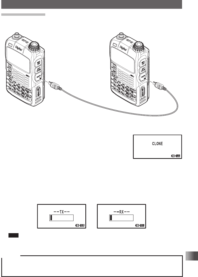
Clone Operation
Data and various settings saved in your transceiver can be copied to another FT1XDR/
DE transceiver.
1 Turn off the power of both FT1XDR/DE transceivers and connect an optional clone
cable (CT-168) to the DATA terminal of each transceiver.
2 Press P while pressing F on each transceiver.
The two transceivers are turned on and placed in the clone
mode.
3 Press % on the receiving side transceiver and B on
the transmission side.
Copying data starts.
When copying starts, the display on the receiving transceiver changes from
[--WAIT--] to [--RX--]. When data transmission begins from the sending transceiver,
the data transmission indicator appears on the LCD, indicating the data transfer is
in progress. The indicator appears on the receiving transceiver, as well when data
reception starts.
Tips When copying is completed, the reception side transceiver returns to the normal mode. The
indication on the LCD of the transmission side transceiver returns from [--TX--] to [CLONE].
4 Turn off the power of both transceivers and disconnect the clone cable.
Caution
When the [ERROR] appears on the LCD during data transfer, copying cannot be completed. Check
the clone cable connection, and redo the clone operation from the beginning.
Time data cannot be copied.
Application for FCC / IC
FCC ID: K6620445X20
IC: 511B-20445X20
144
Functions Used As Needed
Set Mode
Connecting an external device
Using the DATA terminal, the transceiver can support various functions by setting “GPS”,
the internal GPS unit begins outputting the position information data. The position
information of the transceiver can be transferred at approximately 1 second intervals
to the computer so that the position of the transceiver can be displayed in real-time on
programs such as map software.
Tips
• For properties such as communication speed and Input/Output between COM ports.
• For more details, see the Set mode option, [9 APRS] → [17 COM PORT SETTING].
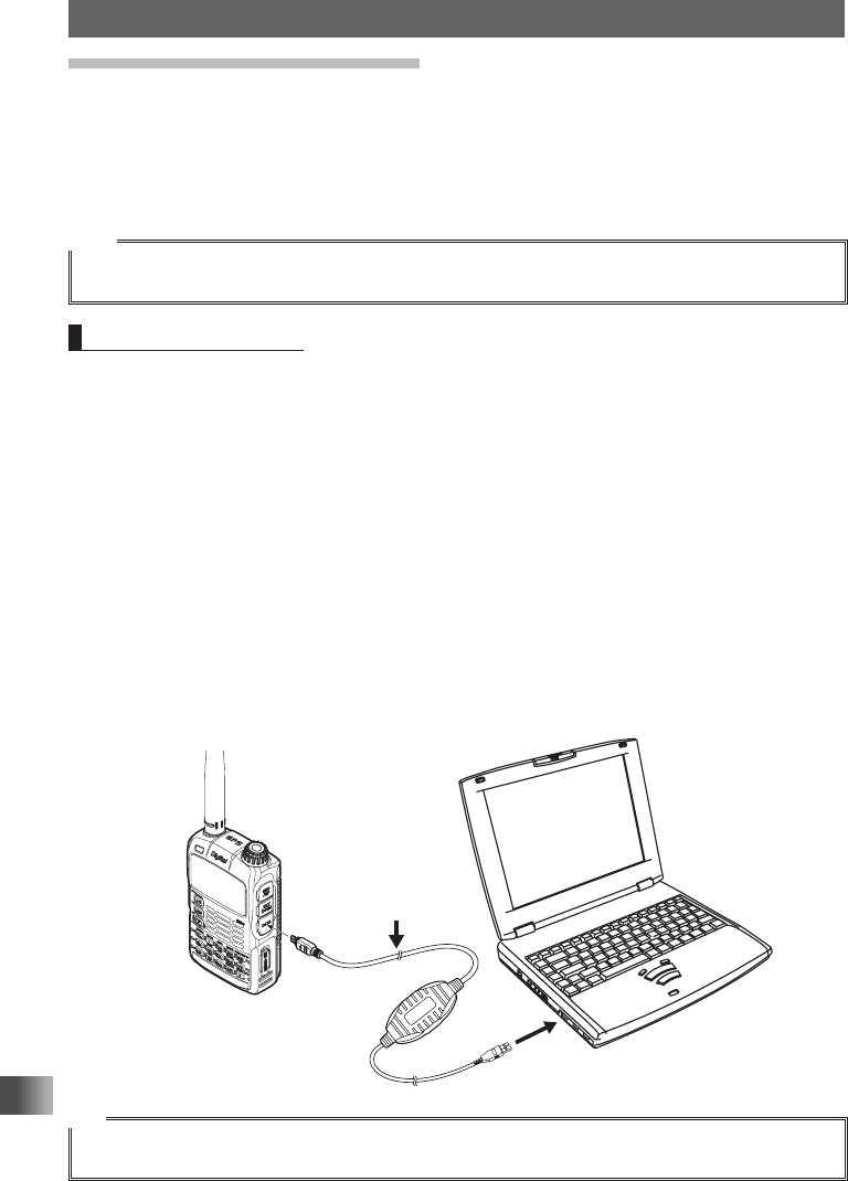
Connecting to a PC
Connecting a PC to the data terminal of the FT1XDR/DE using the PC Connection Cable
(SCU-19) accessory will enable data transmission or updating firmware as described
below.
a. Transmit position location information received by the FT1XDR/DE internal GPS
unit.
By setting [OUTPUT] in [17 COM PORT SETTING] of Set mode option [9 APRS] to details
on settings, see Set mode option [17 COM PORT SETTING] in the APRS Instruction
Manual.
• To show information, software operating with NMEA-0183 specified GGA and RMC
sentence is required.
b. FT1XDR/DE Firmware Updates
When a new firmware update for the FT1XDR/DE is available, go to the YAESU homepage
to download the programming data and update the FT1XDR/DE to its newest state.
SCU-19
(accessory)
Tip
To use the SCU-19, install a dedicated driver to the PC. For downloading the dedicated driver and
installation manual, please go to the YAESU website homepage (http://www.yaesu.com).
Application for FCC / IC
FCC ID: K6620445X20
IC: 511B-20445X20
145
Functions Used As Needed
Set Mode
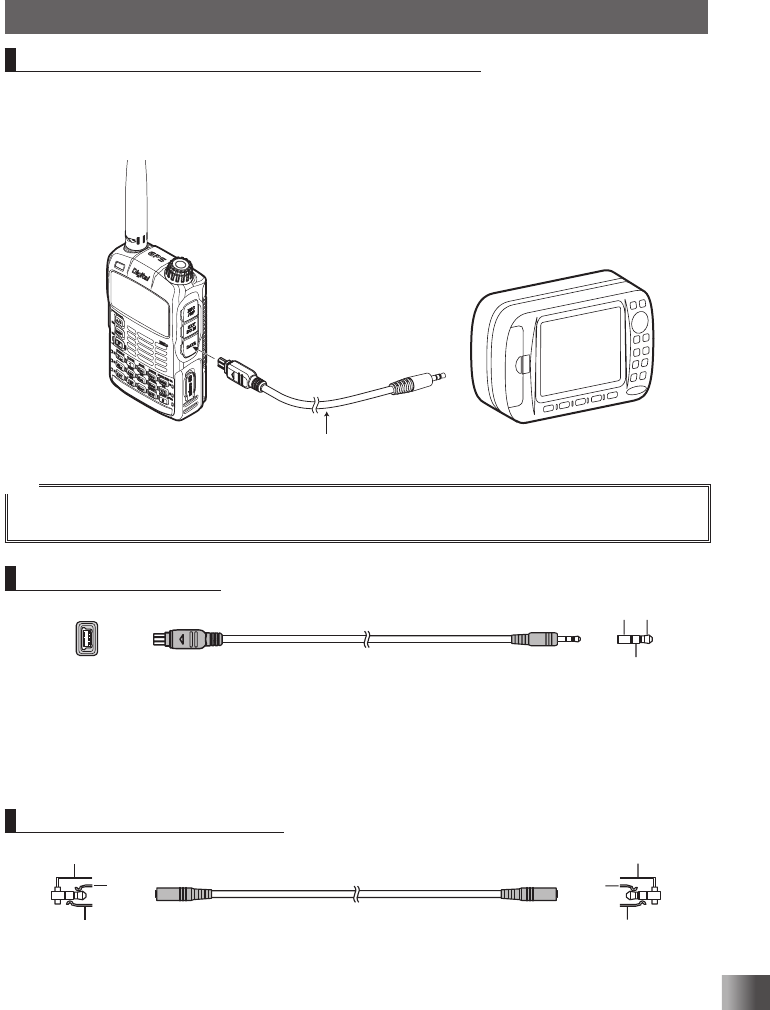
Connecting the FT1XDR/DE to external devices
Position information data can be exchanged between commercially sold GPS receivers
or other external devices by using the optional Data Cable (CT-170) or the Data Cable
2.5Φ (CT-176).
CT-170 (option)
Tip
Connect the Data Cable (CT-170) and the Data Output Cable (CT-176) by referring to the instruction
manual for the GPS device to be used, and cable specifications on the next page.
Data Cable (CT-170)
①
↓
⑤
⑥
↓
⑪
①
②
③
⑦ RXD (Serial data input [FT1XDR/DE ← External
Equipment])
① RXD (Serial data input [FT1XDR/DE ← External
Equipment])
⑧ TXD (Serial data output [FT1XDR/DE → External
Equipment])
② TXD (Serial data output [FT1XDR/DE → External
Equipment])
⑪ GND ③ GND
Data Cable (2.5Φ) (CT-176)
③
①
②
③
①
②
① RXD (Serial data input [FT1XDR/DE ← External
Equipment])
① TXD (Serial data output [FT1XDR/DE → External
Equipment])
② TXD (Serial data output [FT1XDR/DE → External
Equipment])
② RXD (Serial data input [FT1XDR/DE ← External
Equipment])
③ GND ③ GND
Application for FCC / IC
FCC ID: K6620445X20
IC: 511B-20445X20
146
Appendix
Appendix
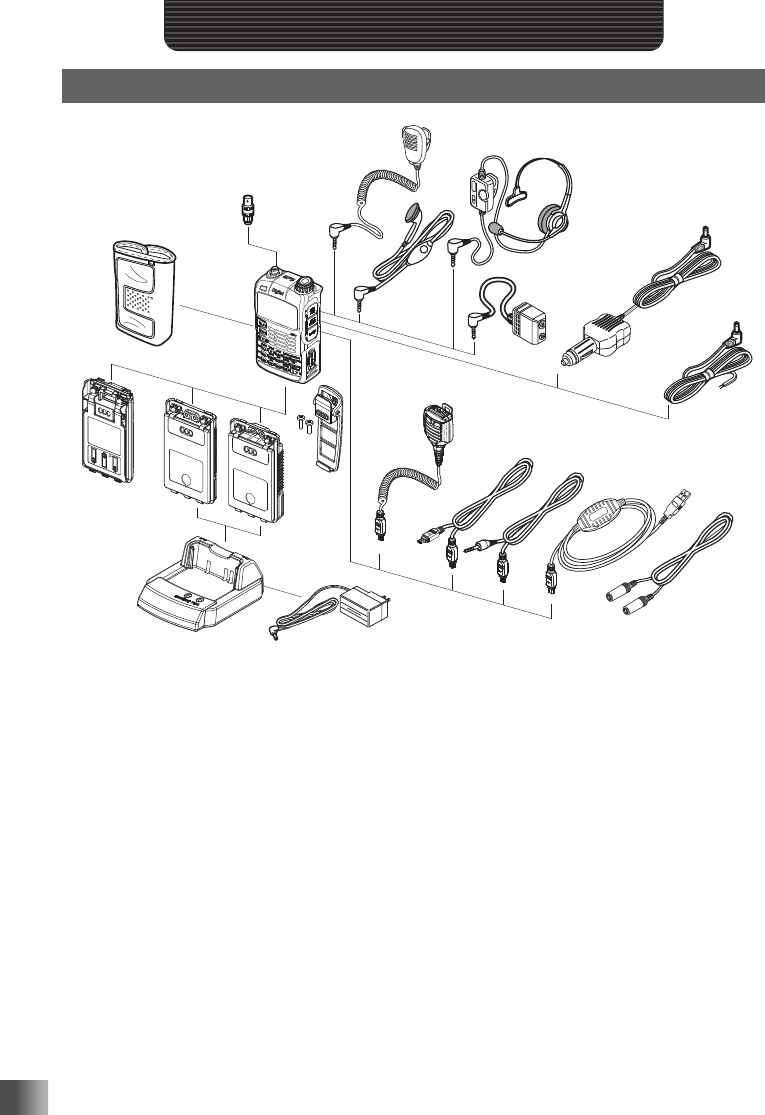
Optional Parts
⑧
⑦
①
②
③
④
⑤
⑥
⑨
⑩
⑫
⑪
⑭
⑮⑯
⑰
⑱
⑬
⑲
① Speaker / Microphone (MH-34B4B)
② Earpiece Microphone (MH-37A4B)
③ VOX Headset (SSM-63A)
④ Microphone Adapter (CT-44)
⑤ DC Cable w/ Noise Filter (SDD-13)
(USA/EXP market only)
⑥ DC Cable (E-DC-6) (USA/EXP market only)
⑦ BNC-to-SMA Adapter (CN-3)
⑧ Soft Case (CSC-97)
⑨ 3x “AA” Cell Battery Case (FBA-39)
⑩ Lithium Ion Battery Packs (FNB-101LI, 7.4 V,
1100 mAh)
⑪ Lithium Ion Battery Packs
(SBR-14LI, 7.2 V, 2200 mAh)
⑫ Rapid Charger (CD-41)
⑬ Battery Charger (PA-48B/C/U*)
Battery Charger (SAD-11B; for USA market)
⑭ Speaker Microphone with Snapshot camera
(MH-85A11U)
⑮ Clone Cable (CT-168)
⑯ Data Cable (CT-170)
⑰ PC Connection Cable (SCU-19)
⑱ Data Cable (2.5Φ) (CT-176)
⑲ Belt Clip (SBH-13)
* “B” suffix is for use with 120 VAC (Type-A plug), “C” suffix is for use with 230-240 VAC (Type-C plug), and
“U” suffix is for use with 230 VAC (Type-BF plug).
Availability of accessories may vary. Some accessories are supplied as standard per local requirements,
while others may be unavailable in some regions. Consult your Yaesu Dealer for details regarding these
and any newly-available options. Connection of any non-Yaesu approved accessory, should it cause dam-
age, may void the Limited Warranty on this apparatus.
Application for FCC / IC
FCC ID: K6620445X20
IC: 511B-20445X20

147
Appendix
If you suspect malfunction Check the following items before requesting for repair.
The transceiver does not turn on.
Is the battery is depleted?
Charge the battery pack after purchase, and when the transceiver has not been used for a long time.
Is the battery pack properly set?
Refer to “Mounting the battery pack” and securely mount the battery pack.
Is the external power supply properly connected?
When using a external power supply, connect an external power supply adapter with a cigarette lighter
plug (SDD-13) or an external power cable (E-DC-6) to this jack.
Is the voltage of the battery pack or the SDD-13 correct?
Be sure that there is a charge left in the battery pack (do not completely discharge). Check that the
output voltage of the SDD-13 is approximately 12V.
There is no sound
Is the level of squelch (or S meter squelch) set too high?
Press the Monitor Switch and check that you can hear white noise.
Adjust the level of squelch (or S meter squelch) when receiving a weak signal.
Is the volume low?
Turn O clockwise while pressing v to increase the sound volume.
Is the tone squelch or DCS on?
When the tone squelch or DCS is on, the sound is not output until the transceiver receives a signal
containing the same tone frequency or DCS code set.
There is no transmission of radio waves.
Are you pressing the p switch properly?
Is the PTT lock on?
Is the Busy TX Block (BCLO function) on?
When the Busy TX Block (BCLO Function) is on, transmission cannot be done when receiving a signal
even if p is pressed. Wait until signal being received stops and then press p.
Is the transmission frequency on an ham radio band?
Transmission cannot be performed on the AM Radio Broadcast Band/ Short Wave Radio Band/ FM
Radio Broadcast Band/ Air Band/ Information Radio Band.
Is the voltage of the battery pack or external power source correct?
Check the remaining charge on the battery pack.
In addition, using a power supply where voltage drops during transmission will prevent the FT1XDR/DE
from operating on full capability.
The keys or O does not respond.
Is the Key Lock or DIAL Lock on?
Application for FCC / IC
FCC ID: K6620445X20
IC: 511B-20445X20

148
Appendix
If you suspect malfunction
The battery pack cannot be charged or battery
power depletes immediately after charging.
Is the battery pack being charged with a charger specified by Yaesu?
Charge the battery pack using the accessory battery charger (PA-48B or SAD-11B) or the rapid charge
cradle (CD-41).
When using a external power supply, use the external power supply adapter with a cigarette lighter plug
(SDD-13) or an external power cable (E-DC-6).
Is the battery pack in use exhausted?
If the “Charging Error” appears on the LCD when charging, there is a chance the battery pack is over
discharged. If the error is repetitively displayed after charging the battery pack several times, the battery
pack may have reached its service life or defective. Battery packs are consumables. Please replace the
battery pack with a new one immediately. Battery packs can be charged and reused up to approximately
300 times.
Depending on the combination for simultaneous reception, there may be internal beats from high frequen-
cies caused by the internal oscillator. This is not a malfunction. (See the calculation formula below: “n” is for
the arbitrary integer). Depending on the combination for simultaneous reception, there may be fluctuations
in reception sensitivity.
Reception Frequency = 16 MHz × n multiplicative
Reception Frequency = 15.6 MHz × n multiplicative
Reception Frequency = 4.9152 MHz × n multiplicative
Reception Frequency = 15.6 MHz × n multiplicative
Reception Frequency = 18.432 MHz × n multiplicative
Upper Side (A-Band) Frequency = (Lower Side (B-band) Frequency ± 46.35 MHz) × n multiplicative
Upper Side (A-Band) Frequency = (Lower Side (B-band) Frequency ± 47.25 MHz) × n multiplicative @
Upper Side (A-band) Mode = NFM
Application for FCC / IC
FCC ID: K6620445X20
IC: 511B-20445X20

149
Appendix
Index
Symbol
A key ................................................................................12
B key ................................................................................12
D key ...................................................................................12
F key ....................................................................................12
H key ...................................................................................12
p switch .................................................................................12
P switch ..............................................................................12
T key ...................................................................................12
A
Activating the GPS function .....................................................68
Adjusting the LCD backlight and
keypad key light brightness level ...107
Adjusting the LCD contrast level ...........................................106
Adjusting the microphone sensitivity .....................................115
Adjusting the squelch level ..............................................37, 121
Adjusting the volume level .......................................................26
AF-DUAL function ....................................................................77
All reset....................................................................................39
AMS .........................................................................................32
AMS transmission mode........................................................112
Analog FM mode .....................................................................32
Antenna .....................................................................................6
Antenna terminal .....................................................................12
APO function .........................................................................127
APRS function .........................................................................67
*web
Assigning a name to a memory channel .................................47
Assigning name to memory bank ............................................49
ATT function ..........................................................................109
Attaching a hand strap.............................................................16
Attaching the belt clip ..............................................................15
Attaching the protective cap ....................................................15
Attenuator function ................................................................109
B
BACK TRACK function screen ................................................74
Backtrack function ...................................................................74
Band scope function ................................................................82
Battery approximate operating time.........................................19
Battery case (FBA-39) .............................................................16
Battery Case 3x “AA” Cell (FBA-39) ......................................146
Battery charger (PA-48B/C/U*) .............................................. 146
Battery charger (SAD-11B; for USA market) .........................146
BCLO function .......................................................................128
Before transmitting radio waves ..............................................11
Being called by the remote station (standby operation) ..........93
Bell...........................................................................................89
Belt clip ......................................................................................6
BNC-to-SMA adapter (CN-3) .................................................146
Bundled items ............................................................................6
Busy Channel Lockout function .............................................128
BUSY/TX lamp ........................................................................12
C
Calling a specific station ..........................................................92
Calling only a specific station (new pager function).................90
Callsign ....................................................................................25
Canceling memory channel registration in memory bank........49
Canceling scanning .................................................................57
Changing home channel frequency ......................................... 45
Changing the display pattern of the PO meter ......................109
Changing the frequency step manually ...................................37
Changing the lighting condition .............................................105
Changing the mode manually .................................................. 38
Changing the number of times the bell rings ...........................89
Changing the opening message displayed
immediately after power-on ...107
Changing the sound volume setting method ......................... 116
Changing the transmission power level ................................... 36
Charging the battery pack .......................................................17
Clock Type function ...............................................................129
Clone cable (CT-168) ............................................................146
Clone operation .....................................................................143
Communicating via the repeater..............................................40
Communicating with a apecific remote station ........................84
Communication mode..............................................................32
Confirming the entered DTMF code by the sound...................80
Connecting the FT1XDR/DE to external devices ..................145
D
Data Cable (2.5Φ) (CT-176) ..................................................146
Data cable (CT-170) ..............................................................146
Data FR mode .........................................................................32
DATA terminal ..........................................................................12
DC cable (E-DC-6) ................................................................146
DC cable w/ noise filter (SDD-13)..........................................146
DCS .........................................................................................84
DCS code ................................................................................86
DCS INVERSION function.....................................................119
Deleting a frequency registered to the
skip search memory channel ...58
Deleting memory channel ........................................................46
Digital communication .............................................................32
Digital mode.............................................................................32
Disabling reception while no signal is received .....................136
Dismounting microSD memory card ........................................ 23
Displaying memory tag ............................................................47
Displaying the GPS screen....................................................103
Displaying the version of the DSP program ...........................115
DTMF function .........................................................................79
Dual reception function ............................................................75
DW ...........................................................................................75
DW TIME function .................................................................124
E
Earpiece microphone (MH-37A4B)........................................146
Enabling no-communication squelch function .......................120
Enter the Set mode..................................................................94
EXT DC IN jack .......................................................................12
External power supply .............................................................21
External power supply for use in vehicle .................................20
F
Flashlight (white LED) .............................................................12
Flow of operation to use the pager function ............................90
FM mode .................................................................................32
Formatting a microSD memory card........................................24
Frequencies of international VHF (marine) radio.....................53
Frequency band for the A-band ............................................... 29
Frequency band for the B-band ...............................................29
FT1XDR/DE ...............................................................................6
FT1XDR/DE Firmware Updates ............................................144
*web: Please download the instruction manuals for GM function and APRS from our home page.
Application for FCC / IC
FCC ID: K6620445X20
IC: 511B-20445X20

150
Appendix
Index
G
GM function .............................................................................65
*web
GPS .........................................................................................68
Group monitor function ............................................................65
*web
H
Home channel .........................................................................45
Home channel dual reception .................................................. 76
HOME VFO ...........................................................................130
I
Input a callsign.........................................................................25
Installing the antenna ..............................................................15
Installing the battery pack ........................................................17
International VHF (marine) radio .............................................52
IPX5 .........................................................................................11
L
Listen to the international VHF (marine) radio ......................... 52
Listening radio broadcast with AF-DUAL reception function ...77
Lithium ion battery packs (FNB-101LI, 7.4 V, 1100 mAh) ...... 146
Lithium ion battery packs (SBR-14LI, 7.2 V, 2200 mAh) .......146
LOCK function .......................................................................131
Locking keys ............................................................................39
Locking switches .....................................................................39
M
Measuring the battery voltage and the transceiver
temperature ...........................................................................108
Memory bank link scan ............................................................62
Memory channel dual reception ..............................................76
Memory channel protect function ..........................................118
Memory channel scanning.......................................................59
Memory channel write function ..............................................118
Memory functions ....................................................................42
Memory tag..............................................................................46
Method of positioning by GPS .................................................70
Microphone adapter (CT-44) .................................................146
Microphone gain .................................................................... 115
microSD memory card .............................................................22
Mounting microSD memory card .............................................22
Mute.........................................................................................35
Muting audio ............................................................................35
Muting the key operation confirmation tone...........................128
N
New pager function..................................................................90
Notification of a call from a remote station by the bell .............89
Notification of call from the remote station by
vibration of the vibrator ....88
O
Operating band ........................................................................27
Optional parts ........................................................................146
P
Packet communication ..........................................................142
Password function .................................................................133
PC connection cable (SCU-19) .........................................6, 146
Performing communication ................................................25, 31
Performing programmable memory channel scan...................64
Permitting transfer of home channel frequency to VFO ........130
PMS .........................................................................................63
PMS memory channel .............................................................63
Positioning by GPS..................................................................70
Power cable .............................................................................20
Power supply voltage measurement function ........................ 108
PR FREQUENCY function ....................................................120
Preset receiver memory channel ............................................. 51
Preventing accidental transmission .......................................128
Priority memory channel ..........................................................75
Programmable memory channel .............................................63
Programmable memory channel scan ..................................... 63
Prohibiting registration to memory channel ........................... 118
Protective plate for battery pack ................................................6
PTT DELAY function ..............................................................134
R
Rapid charger (CD-41) ..........................................................146
Real-time navigation function ..................................................73
Recalling a memory channel ...................................................44
Recalling home channel ..........................................................45
Recalling memory bank ...........................................................49
Reception frequencies .............................................................28
Reception mode (radio wave type) .......................................... 38
Reception Save function........................................................136
Reducing receiver sensitivity .................................................109
Register to a memory channel.................................................43
Registering a memory channel in a memory bank ..................48
Registering CALLSIGN..........................................................141
Registering to a memory channel with the
lowest memory channel number....118
Registering to a programmable memory channel....................63
Registering your current position ............................................. 74
Registering your favorite preset receiver
memory channels in memory bank.....51
Removing the battery pack ......................................................17
Repeater operation ..................................................................40
Resetting the Set mode options ..............................................94
Restoring deleted memory channel ......................................... 46
Restoring to defaults................................................................39
Restricting the continuous transmission time ........................136
RPT ARS function ..................................................................134
RPT SHIFT FREQ function ...................................................135
RPT SHIFT function ..............................................................135
S
S meter squelch function .......................................................121
Safety precautions .....................................................................7
Saving/ Loading data to/from microSD memory card ............ 138
Saving/ Loading GROUP ID information to/from
microSD memory card .......139
Saving/ Loading memory channel information
to/from microSD memory card .......138
SCAN LAMP function ............................................................125
SCAN RE-START function ....................................................125
Scanning a memory bank ........................................................61
Scanning function ....................................................................56
Scanning only the selected memory channel ..........................61
*web: Please download the instruction manuals for GM function and APRS from our home page.
Application for FCC / IC
FCC ID: K6620445X20
IC: 511B-20445X20

151
Appendix
Index
Searching for signals with the signal strength graph ...............82
Searching for the frequency of the DCS used by the
remote station .....87
Searching for the frequency of the
tone squelch used by the remote station ...... 86
Select a tone squelch type ......................................................84
Selected memory channel .......................................................60
Selecting a band ......................................................................29
Selecting a DCS code .............................................................86
Selecting a display language .................................................106
Selecting a frequency band .....................................................29
Selecting a reception method when scanning stops ...............59
Selecting a tone frequency ......................................................85
Selecting an operating band ....................................................27
Selecting communication mode...............................................32
Selecting vibrator operation mode ........................................... 88
Sending a DTMF code manually .............................................81
Sending the registered DTMF code.........................................80
Set mode .................................................................................94
Set mode option list .................................................................95
Setting clock time ....................................................................34
Setting interval to save GPS position information .................130
Setting memory bank link ......................................................117
Setting the ARS function........................................................134
Setting the clock shift for the micro computer........................129
Setting the code of your station ...............................................91
Setting the conditions for locking ...........................................131
Setting the direction for repeater shift....................................135
Setting the display method for BACKTRACK ........................104
Setting the display method of the remote station
information .............................................................................104
Setting the DTMF code............................................................79
Setting the frequency selection range for
operation in the VFO mode ....137
Setting the operation of T .................................................132
Setting the operation of Monitor key ......................................132
Setting the optional microphone with camera for use............140
Setting the pop up time of the remote station information ..... 112
Setting the PTT delay time ....................................................134
Setting the range for repeater shift ........................................135
Setting the range for SCAN ...................................................126
Setting the resumption time of radio reception ........................78
Setting the search channels for the BAND SCOPE
function ..................................................................................105
Setting the signal strength to output sound ...........................121
Setting the sound and speed during tone search ..................123
Setting the squelch type for the digital mode.........................112
Setting the squelch type for transmission and reception .......122
Setting the surveillance interval time for priority channels.....124
Setting the time signal .............................................................34
Setting the time to resume scan ............................................124
Setting the transmission modulation level ............................. 110
Simultaneous radio broadcast reception .................................77
Simultaneous signal reception over the other frequency
while listening to the radio .......................................................77
Skip memory channel ..............................................................60
Skip search memory ................................................................57
Smart navigation function ........................................................73
Soft case (CSC-97) ...............................................................146
Speaker / microphone (MH-34B4B) ......................................146
Speaker Microphone with
Snapshot camera (MH-85A11U) .......82, 146
Specifying a selected memory channel ...................................60
Specifying a skip memory channel ..........................................60
Specifying the frequency you do not want to scan ..................58
Split memory............................................................................44
SQL EXPANTION function ....................................................122
SQL LEVEL function .............................................................. 121
Squelch level ...........................................................................37
STANDBY BEEP setting ........................................................ 114
Switching between AM antennas.............................................33
Switching between digital and analog mode ......................... 111
T
Taking picture ..........................................................................82
Taking picture with the optional camera
mounted on speaker microphone .........82
Temperature measurement function ...................................... 108
Time signal tone ......................................................................34
Timer function ........................................................................132
Tone Calling (1750 Hz) ............................................................40
Tone Search function ............................................................. 123
Tone squelch ...........................................................................84
TOT function ..........................................................................136
Transmission power level ........................................................36
Transmit and receive a DCS code with a inverted phase ......119
Transmitting GPS data ..........................................................144
Tuning in to a frequency ..........................................................30
Turning illumination off when scanning stops ........................ 125
Turning off the BUSY indicator ..............................................129
Turning off the power automatically ....................................... 127
Turning on the transceiver .......................................................25
Turning on/off the transceiver at the specified time ............... 132
U
Usable microSD memory card.................................................22
Using memory bank.................................................................48
Using the memory ...................................................................42
Using the scanning function ....................................................56
Using the white LED as a flashlight .......................................131
V
V/D mode.................................................................................32
VFO dual reception..................................................................75
VFO MODE function ..............................................................137
VFO scan.................................................................................56
Vibrator ....................................................................................88
Vibrator operation mode ..........................................................88
Voice FR mode ........................................................................32
VOX headset (SSM-63A) ......................................................146
W
Worldwide short wave broadcast .............................................54
Application for FCC / IC
FCC ID: K6620445X20
IC: 511B-20445X20

152
Appendix
Specifications
General
Frequency Range
A (Main) Band RX: 0.5 ~ 1.8 MHz (AM Radio)
1.8 ~ 30 MHz (SW Radio)
30 ~ 76 MHz (50 MHz HAM: USA version)
30 ~ 88 MHz (50 MHz HAM: EXP/EU version)
76 ~ 108 MHz (FM Radio: USA version)
88 ~ 108 MHz (FM Radio: EXP/EU version)
108 ~ 137 MHz (Air Band)
137 ~ 174 MHz (144 MHz HAM)
174 ~ 222 MHz (VHF Band)
222 ~ 420 MHz (GEN1)
420 ~ 470 MHz (430 MHz HAM)
470 ~ 774 MHz (UHF Band: USA version)
470 ~ 800 MHz (UHF Band: EXP/EU version)
803 ~ 999 MHz (GEN2, Cellular Blocked: USA version)
800 ~ 999 MHz (GEN2: EXP/EU version)
B (Sub) Band RX: 108 ~ 137 MHz (Air Band)
137 ~ 174 MHz (144 MHz HAM)
174 ~ 222 MHz (VHF Band)
222 ~ 420 MHz (GEN1)
420 ~ 470 MHz (430 MHz HAM)
470 ~ 580 MHz (UHF Band)
TX: 144 ~ 146 MHz or 144 ~ 148 MHz
430 ~ 440 MHz or 430 ~ 450 MHz
Channel Steps: 5/6.25/8.33/9/10/12.5/15/20/25/50/100 kHz
Frequency Stability: ±2.5 ppm (–20 °C to +60 °C [–4 °F to +140 °F])
Emission Type: F1D, F2D, F3E, F7W
Supply Voltage: Nominal: 7.4 V DC (Negative Ground)
Operating: 4 – 14 V (Negative Ground, EXT DC JACK)
11 – 16 V (Negative Ground, EXT DC JACK with SDD-13)
7.4 V DC (Negative Ground)
Current Consumption: 150 mA (Mono band Receive)
220 mA (Dual band Receive)
100 mA (Mono band Receive, Standby)
150 mA (Dual band Receive, Standby)
45 mA (Mono band Receive, Standby, Saver On “Save Ratio 1:5”)
45 mA (Dual band Receive, Standby, Saver On “Save Ratio 1:5”)
+30 mA (GPS On)
+65 mA (Digital)
600
μ
A (Auto Power Off)
1.7 A (5 W TX, 144 MHz 7.4 V DC)
2.0 A (5 W TX, 430 MHz 7.4 V DC)
Operating Temperature: –20 °C to +60 °C [–4 °F to +140 °F]
Case Size (W × H × D): 60 × 95 × 32.5 mm (2.4″ × 3.7″ × 1.28″) w/o knob & antenna
Weight (Approx.): 290 g (10.23 oz) with SBR-14LI & Antenna
Application for FCC / IC
FCC ID: K6620445X20
IC: 511B-20445X20

153
Appendix
Specifications
Transmitter
RF Power Output: 5 W (@ 7.4 V or EXT DC)
Modulation Type: F1D, F2D, F3E: Variable Reactance modulation
F7W: 4 FSK (C4FM)
Spurious Emission: At least 60 dB below (@TX Power Hi, L3, L2)
At least 50 dB below (@TX Power L1)
Receiver
Circuit Type: AM, NFM: Double-Conversion Super heterodyne
AM/FM Radio: Single-Conversion Super heterodyne
Intermediate Frequencies: 1st: 47.25MHz (AM, NFM A Band)
1st: 46.35MHz (AM, NFM B Band)
2nd: 450 kHz (AM, NFM)
1st: 130 kHz (AM/FM Radio)
Sensitivity: 3
μ
V for 10 dB SN (0.5 ~ 30 MHz, AM)
0.35
μ
V TYP for 12 dB SINAD (30 ~ 54 MHz, NFM)
1
μ
V TYP for 12 dB SINAD (54 ~ 76 (88) MHz, NFM)
1.5
μ
V TYP for 12 dB SINAD (76 (88) ~ 108 MHz, WFM)
1.5
μ
V TYP for 10 dB SN (108 ~ 137 MHz, AM)
0.2
μ
V for 12 dB SINAD (137 ~ 140 MHz, NFM)
0.16
μ
V for 12 dB SINAD (140 ~ 150 MHz, NFM)
0.2
μ
V for 12 dB SINAD (150 ~ 174 MHz, NFM)
1
μ
V for 12 dB SINAD (174 ~ 222 MHz, NFM)
0.5
μ
V for 12 dB SINAD (300 ~ 350 MHz, NFM)
0.2
μ
V for 12 dB SINAD (350 ~ 400 MHz, NFM)
0.16
μ
V for 12 dB SINAD (400 ~ 470 MHz, NFM)
1.5
μ
V for 12 dB SINAD (470 ~ 540 MHz, NFM)
3
μ
V TYP for 12 dB SINAD (540 ~ 800 MHz, NFM)
1.5
μ
V TYP for 12 dB SINAD (800 ~ 999 MHz, NFM, Cellular Blocked)
0.19
μ
V TYP for BER 1% (Digital Mode)
Selectivity: NFM, AM 12 kHz / 35 kHz (–6 dB / –60 dB)
AF Output: 200 mW (8 Ω for 10 % THD 7.4 V)
400 mW (8 Ω for 10 % THD 13.8 V)
Specifications are subject to change without notice, and are guaranteed within the 144/222 (USA ver-
sion)/430 MHz amateur bands only.
Application for FCC / IC
FCC ID: K6620445X20
IC: 511B-20445X20
154
1. Changes or modifications to this device not expressly approved by YAESU
MUSEN could void the user’s authorization to operate this device.
2. This device complies with part 15 of the FCC Rules. Operation is subject to the
following two conditions: (1) This device may not cause harmful interference, and
(2) this device must accept any interference including received, interference that
may cause undesired operation.
3. The scanning receiver in this equipment is incapable of tuning, or readily being
altered, by the User to operate within the frequency bands allocated to the
Domestic public Cellular Telecommunications Service in Part 22.
Part 15.21: Changes or modifications to this device not expressly approved by
YAESU MUSEN could void the user’s authorization to operate this device.
DECLARATION BY MANUFACTURER
The Scanner receiver is not a digital scanner and is incapable of being converted or
modified to a digital scanner receiver by any user.
WARNING: MODIFICATION OF THIS DEVICE TO RECEIVE CELLULAR
RADIOTELEPHONE SERVICE SIGNALS IS PROHIBITED UNDER FCC RULES
AND FEDERAL LAW.
Disposal of your Electronic and Electric Equipment
Products with the symbol (crossed-out wheeled bin) cannot be disposed as household
waste.
Electronic and Electric Equipment should be recycled at a facility capable of
handling these items and their waste by products.
In EU countries, please contact your local equipment supplier representative or
service center for information about the waste collection system in your coun-
try.
This transceiver works on frequencies which are not
generally permitted.
As for the actual usage, the user has to possess an
amateur radio licence.
Usage is allowed only in the frequency bands which
are allocated for amateur radios.
Attention in case of use
List of national codes
AT BE BG CY CZ DE
DK ES EE FI FR GB
GR HR HU IE IT LT
LU LV MT NL PL PT
RO SK SI SE CH IS
LI NO – – – –
Application for FCC / IC
FCC ID: K6620445X20
IC: 511B-20445X20

1505X-FO
YAESU MUSEN CO., LTD.
Tennozu Parkside Building
2-5-8 Higashi-Shinagawa, Shinagawa-ku, Tokyo
140-0002 Japan
YAESU USA
6125 Phyllis Drive, Cypress, CA 90630, U.S.A.
YAESU UK
Unit 12, Sun Valley Business Park, Winnall Close
Winchester, Hampshire, SO23 0LB, U.K.
Printed in Japan
Copyright 2015
YAESU MUSEN CO., LTD.
All rights reserved.
No portion of this manual
may be reproduced
without the permission of
YAESU MUSEN CO., LTD.
Application for FCC / IC
FCC ID: K6620445X20
IC: 511B-20445X20