Yaesu Musen 20445X20 AMATEUR RADIO WITH SCANNING RECEIVER User Manual 7
Yaesu Musen Co., Ltd. AMATEUR RADIO WITH SCANNING RECEIVER 7
Contents
User Manual 7

100
Functions Used As Needed
Set Mode
Set mode option No./
setting Item Description of function Setting Item
(Bold letters: Default)
Reference
page
9-6 APRS MSG GROUP Set group filter for receiving mes-
sages.
G1: ALL******
G2: CQ*******
G3: QST******
G4: YAESU****
G5:
B1: BLN******
B2: BLN*
B3: BLN*
–
9-7 APRS MSG TXT Enter standard message text 1 to
7ch
1 to 8 ch –
9-8 APRS MUTE Turn on/off the B-band AF muting
function when APRS is set.
ON / OFF –
9-9 APRS POPUP Set such as a beacon type, mes-
sage type and time for pop-up
display.
Mic-E:
OFF / ALL2s to ALL60s /
ALLCNT / BND2s to BND60s /
BNDCNT ALL10s
POSITION:
OFF / ALL2s to ALL60s /
ALLCNT / BND2s to BND60s /
BNDCNT ALL10s
WEATHER:
OFF / ALL2s to ALL60s /
ALLCNT / BND2s to BND60s /
BNDCNT ALL10s
OBJECT:
OFF / ALL2s to ALL60s /
ALLCNT / BND2s to BND60s /
BNDCNT ALL10s
ITEM:
OFF / ALL2s to ALL60s /
ALLCNT / BND2s to BND60s /
BNDCNT ALL10s
STATUS:
OFF / ALL2s to ALL60s /
ALLCNT / BND2s to BND60s /
BNDCNT ALL10s
OTHER:
OFF / ALL2s to ALL60s /
ALLCNT / BND2s to BND60s /
BNDCNT ALL10s
MY PACKET:
OFF / ALL2s to ALL60s /
ALLCNT / BND2s to BND60s /
BNDCNT ALL10s
MSG:
OFF / ALL2s to ALL60s /
ALLCNT / BND2s to BND60s /
BNDCNT ALL10s
–
Application for FCC / IC
FCC ID: K6620445X20
IC: 511B-20445X20

101
Functions Used As Needed
Set Mode
Set mode option No./
setting Item Description of function Setting Item
(Bold letters: Default)
Reference
page
9-9 APRS POPUP Set the beacon type, the message
type and the time of the popup
display.
GRP:
OFF / ALL2s to ALL60s /
ALLCNT / BND2s to BND60s /
BNDCNT ALL10s
BLN:
OFF / ALL2s to ALL60s /
ALLCNT / BND2s to BND60s /
BNDCNT ALL10s
MY MSG:
OFF / BND2s to BND60s /
BND10s
DUP.BCN:
OFF / BND2s to BND60s /
BND10s
DUP.MSG:
OFF / BND2s to BND60s /
BND10s
ACK.REJ:
OFF / BND2s to BND60s /
BND10s
OTHER MSG:
OFF / BND2s to BND60s /
BND10s
–
9-10 APRS RINGER Turn on/off the bell when a bea-
con is received.
Mic-E: ON / OFF
POSITION: ON / OFF
WEATHER: ON / OFF
OBJECT: ON / OFF
ITEM: ON / OFF
STATUS: ON / OFF
OTHER: ON / OFF
MY PACKET: ON / OFF
MSG: ON / OFF
GRP: ON / OFF
BLN: ON / OFF
MY MSG: ON / OFF
DUP.BCN: ON / OFF
DUP.MSG: ON / OFF
ACK.REJ: ON / OFF
OTHER MSG: ON / OFF
TX BCN: ON / OFF
TX MSG: ON / OFF
–
9-11 APRS UNIT Select the units for APRS display. Position: MM.MM' / MM'SS'
Distance: km / mile
Speed: km/h / knot / mph
Altitude: m / ft
Temp: °C / °F
Rain: mm / inch
Wind: m/s / mph
–
9-12 APRS TX DELAY Set the data sending delay time. 100ms / 150ms / 200ms /
250ms / 300ms / 400ms /
500ms / 750ms / 1000ms
–
Application for FCC / IC
FCC ID: K6620445X20
IC: 511B-20445X20

102
Functions Used As Needed
Set Mode
Set mode option No./
setting Item Description of function Setting Item
(Bold letters: Default)
Reference
page
9-13 BEACON INFO Set the transmission beacon in-
formation.
AMBIGUITY:
OFF / 1 dig to 4dig
SPD / CSE: ON / OFF
ALTITUDE: ON / OFF
–
9-14 BEACON
INTERVAL
Set a beacon automatic sending
interval.
30sec / 1min / 2min / 3min /
5min / 10min / 15min / 20min /
30min / 60min
–
9-15 BEACON STATS
TXT
Input setting for status text. S.TXT: ON / OFF
TX RATE: 1/1 to 1/8
1 to 5 CH
–
9-16 BEACON TX Select automatic or manual send-
ing of beacon.
AUTO / MANUAL / SMART –
9-17 COM PORT
SETTING
Set the COM port. STATUS: ON / OFF
SPEED:
4800 / 9600 / 19200 / 38400
INPUT: OFF / GPS
OUTPUT: OFF / GPS / WAY.P
WAYPOINT:
NMEA9 / NMEA6 / NMEA7 /
NMEA8
Mic-E: ON / OFF
POSIT: ON / OFF
WEATHER: ON / OFF
OBJECT: ON / OFF
ITEM: ON / OFF
–
9-18 DIGI PATH Select a digital repeater route. P1 OFF
P2 1 WIDE1-1
P3 1 WIDE1-1 / 2 WIDE2-1
P4 1 · · · · · · – · · / 2 · · · · · · – · ·
P5 1 · · · · · · – · · / 2 · · · · · · – · ·
P6 1 · · · · · · – · · / 2 · · · · · · – · ·
P7 1 · · · · · · – · · / 2 · · · · · · – · ·
P8 1 · · · · · · – · · to 8 · · · · · · – · ·
–
9-19 GPS DATUM Select a datum used for the GPS
function.
WGS-84 / Tokyo Mean /
Tokyo Japan / Tokyo Korea /
Tokyo Okinawa
–
9-20 GPS POWER Turn on/off the GPS function. GPS ON / GPS OFF –
9-21 GPS TIME SET Turn on/off the GPS time and date
automatic acquisition function.
AUTO / MANUAL –
9-22 GPS UNIT Select the units for GPS display. Position: .MMM' / 'SS''
Speed: km/h / Knot / mph
Altitude: m / ft
–
9-23 CALLSIGN (APRS) Specify the callsign of your sta-
tion.
– –
9-24 MY POSITION Set the position for your station. GPS / Lat N * **°**.**' /
LON* **°**.**'
P1 to P10
–
9-25 MY SYMBOL Set the symbol for your station. 45 Icon –
Application for FCC / IC
FCC ID: K6620445X20
IC: 511B-20445X20
103
Functions Used As Needed
Set Mode
Set mode option No./
setting Item Description of function Setting Item
(Bold letters: Default)
Reference
page
9-26 POSITION
COMMENT
Set up the position comment func-
tion.
Off Duty / En Route /
In Service / Returning /
Committed / Special / Priority /
Custom 0 to 6 / EMERGENCY!
–
9-27 SmartBeaconing Set the smart beaconing function. STATUS:
OFF / TYPE1 / TYPE2 / TYPE3
LOW SPD: 2mph to 30mph
HIGH SPD: 31mph to 90mph
SLOW RATE: 1min to 100min
FAST RATE: 10sec to 180sec
TURN ANGL: 5° to 90°
TURN SLOP: 1 to 255
TURN TIME: 5sec to 180sec
–
9-28 TIME ZONE Set the time zone. UTC ±13.0 H / UTC+0:00 –
* For more details of functions, refer to the APRS Section in the instruction manual.
10 SD CARD
10-1 BACKUP Write or read the information
about your transceiver into or
from the micro SD memory card.
Write to SD / Read from SD 138
10-2 MEMORY CH Write or read the memory channel
information into or from the micro
SD memory card.
Write to SD / Read from SD 138
10-3 GROUP ID Write or read GROUP ID infor-
mation into or from the micro SD
memory card.
Write to SD / Read from SD 139
10-4 FORMAT Format the micro SD memory
card.
Format 24
11 OPTION
11-1 USB CAMERA Set the USB CAMERA image size
and resolution.
SIZE: 160×120 / 320×240
QUALITY: LOW / NORMAL /
HIGH
140
12 CALLSIGN Set the CALLSIGN. – 141
Displaying the GPS screen.
When using the GPS function, you can display the GPS information on the LCD.
Enter the Set mode:
1 Press and hold M for over 1 second.
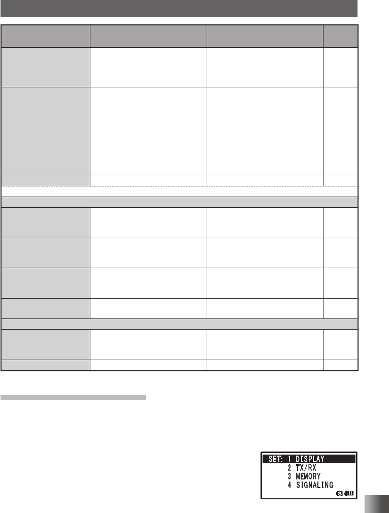
2 Turn O to select [1 DISPLAY].
3 Press H.
4 Turn O to select [1 GPS INFO].
5 Press H to display the GPS information on the LCD.
Application for FCC / IC
FCC ID: K6620445X20
IC: 511B-20445X20
104
Functions Used As Needed
Set Mode
Setting the display method of the remote station information
Set the display method of the remote station information when using the GM Function.
Enter the Set mode:
1 Press and hold M for over 1 second.
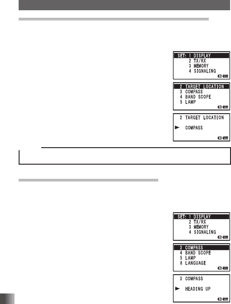
2 Turn O to select [1 DISPLAY].
3 Press H.
4 Turn O to select [2 TARGET LOCATION].
5 Press H.
6 Turn O to select the display method.
COMPASS: Compass appears.
NUMERIC: Longitude and latitude appear.
7 Press p to set the selected display method, and exit from
the Set mode.
Caution
When the NUMERIC is selected, only the location information of the remote station appears on the
LCD. The BACKTRACK function is not activated.
Setting the display method for BACKTRACK
You can set the BACKTRACK screen display method.
Enter the Set mode:
1 Press and hold M for over 1 second.
2 Turn O to select [1 DISPLAY].
3 Press H.
4 Turn O to select [3 COMPASS].
5 Press H.
6 Turn O to select the display method.
HEADING UP: Heading direction is indicated upward.
NORTH UP: North direction is indicated upward.
7 Press p to save the selected display setting and exit the
set mode.
Application for FCC / IC
FCC ID: K6620445X20
IC: 511B-20445X20
105
Functions Used As Needed
Set Mode
Setting the search channels for the BAND SCOPE function
You can set the number of channels to be displayed for the band scope when the BAND
SCOPE function is used.
Enter the Set mode:
1 Press and hold M for over 1 second.
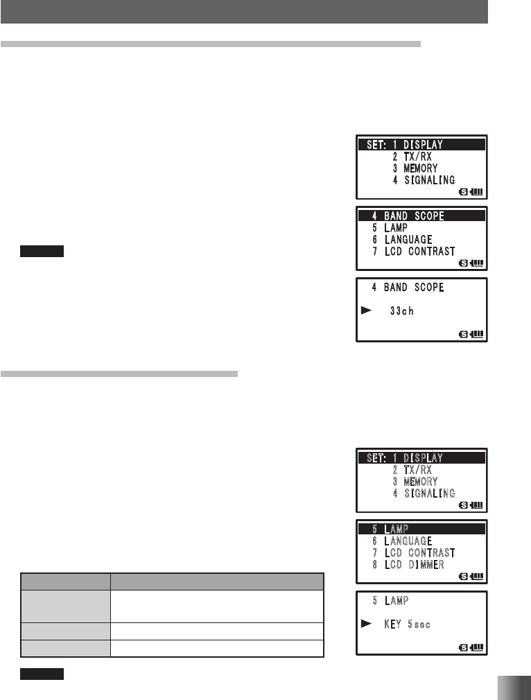
2 Turn O to select [1 DISPLAY].
3 Press H.
4 Turn O to select [4 BAND SCOPE].
5 Press H.
6 Turn O to select the number of channels to search for.
11ch / 19ch / 33ch / 49ch / 101ch
Remark Default: 33ch
7 Press p to set the number of channels to search for, and
exit the Set mode.
Changing the Lighting Condition
You can change the LCD and key lighting condition.
Enter the Set mode:
1 Press and hold M for over 1 second.
2 Turn O to select [1 DISPLAY].
3 Press H.
4 Turn O to select [5 LAMP].
5 Press H.
6 Turn O to select a lighting condition.
Select a lighting condition with reference to the following
table:
Display Lighting Condition
2 SEC (KEY) to
10 SEC (KEY)
When O dial or a key is pressed, the LCD
and keys light up for the set time.
CONTINUOUS The LCD and keys light up continuously.
OFF The LCD and keys do not light.
Remark Default: Key, 5 seconds
7 Press p to save the lighting condition, and exit the Set mode.
䎃 䎘 䎃 䎯 䎤䎰䎳
䎃䎃䎃䎃 䎃 䎮 䎨 䎼 䎃䎘
䏖䏈䏆
䎃
䎶䎨䎷 䎝 䎃䎃䎔䎃 䎧 䎬 䎶 䎳䎯䎤䎼
䎃䎃䎃䎃䎃䎃䎃䎃䎕 䎃䎷 䎻 䎒 䎵 䎻
䎃䎃䎃䎃䎃䎃䫹䎃 䎖 䎃䎰䎨䎰䎲䎵䎼
䎃䎃䎃䎃䎃䎃䎃䎃䎗 䎃 䎶 䎬 䎪 䎱 䎤 䎯 䎬 䎱䎪
䎘 䎃 䎯 䎤䎰䎳
䎃䎙 䎃䎯 䎤 䎱 䎪 䎸 䎤 䎪 䎨
䎃 䎚 䎃䎯 䎦 䎧 䎃䎦䎲䎱䎷䎵䎤䎶䎷
䎃 䎛 䎃䎯 䎦 䎧 䎃䎧 䎬 䎰䎰䎨䎵
Application for FCC / IC
FCC ID: K6620445X20
IC: 511B-20445X20
106
Functions Used As Needed
Set Mode
Selecting a Display Language
You can select a display language from Japanese and English.
Enter the Set mode:
1 Press and hold M for over 1 second.
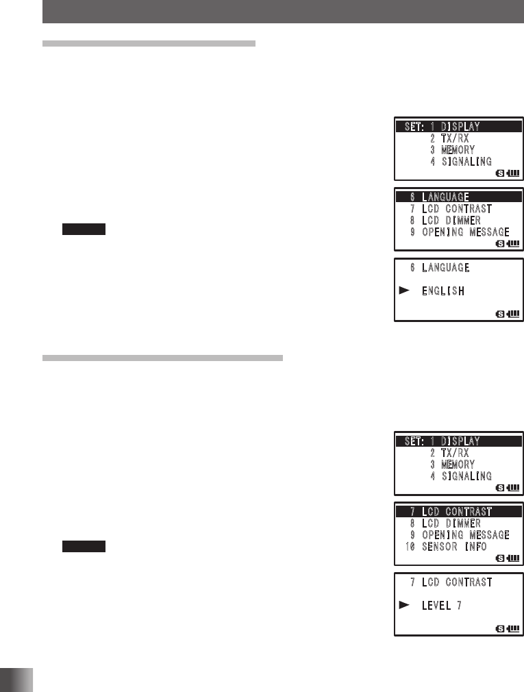
2 Turn O to select [1 DISPLAY].
3 Press H.
4 Turn O to select [6 LANGUAGE].
5 Press H.
6 Turn O to select a language.
Select [JAPANESE] or [ENGLISH].
Remark Default: Japanese
7 Press p to save the selected display language, and exit
the Set mode.
Adjusting the LCD Contrast Level
You can adjust the LCD contrast level.
Enter the Set mode:
1 Press and hold M for over 1 second.
2 Turn O to select [1 DISPLAY].
3 Press H.
4 Turn O to select [7 LCD CONTRAST].
5 Press H.
6 Turn O to select a contrast level.
Select from among LEVEL 1 (LIGHT) to LEVEL 15 (DARK).
Remark Default: LEVEL 7
7 Press p to save the selected contrast, and exit the Set
mode.
䎃 䎙 䎃 䎯 䎤 䎱 䎪 䎸 䎤 䎪 䎨
䎃䎃䎃䎃 䎃 䎨 䎱 䎪 䎯 䎬 䎶 䎫
䎃
䎶䎨䎷 䎝 䎃䎃䎔䎃 䎧 䎬 䎶 䎳䎯䎤䎼
䎃䎃䎃䎃䎃䎃䎃䎃䎕 䎃䎷 䎻 䎒 䎵 䎻
䎃䎃䎃䎃䎃䎃䫹䎃 䎖 䎃䎰䎨䎰䎲䎵䎼
䎃䎃䎃䎃䎃䎃䎃䎃䎗 䎃 䎶 䎬 䎪 䎱 䎤 䎯 䎬 䎱䎪
䎙 䎃 䎯 䎤 䎱䎪 䎸 䎤 䎪 䎨
䎃䎚 䎃䎯 䎦 䎧 䎃䎦䎲䎱䎷䎵䎤䎶䎷
䎃 䎛 䎃䎯 䎦 䎧 䎃䎧 䎬 䎰䎰䎨䎵
䎃 䎜 䎃䎲䎳䎨 䎱 䎬 䎱䎪䎃䎰 䎨䎶䎶䎤䎪䎨
䎃 䎚 䎃 䎯 䎦 䎧 䎃 䎦 䎲䎱䎷䎵䎤䎶䎷
䎃䎃䎃䎃 䎃 䎯 䎨 䎹 䎨 䎯 䎃 䎚
䎃
䎶䎨䎷 䎝 䎃䎃䎔䎃 䎧 䎬 䎶 䎳䎯䎤䎼
䎃䎃䎃䎃䎃䎃䎃䎃䎕 䎃䎷 䎻 䎒 䎵 䎻
䎃䎃䎃䎃䎃䎃䫹䎃 䎖 䎃䎰䎨䎰䎲䎵䎼
䎃䎃䎃䎃䎃䎃䎃䎃䎗 䎃 䎶 䎬 䎪 䎱 䎤 䎯 䎬 䎱䎪
䎚 䎃 䎯 䎦 䎧 䎃 䎦 䎲䎱䎷䎵䎤䎶䎷
䎃䎛 䎃䎯 䎦 䎧 䎃䎧 䎬 䎰䎰䎨䎵
䎃 䎜 䎃䎲䎳䎨 䎱 䎬 䎱䎪䎃䎰 䎨䎶䎶䎤䎪䎨
䎔䎓䎃䎶 䎨 䎱 䎶 䎲 䎵 䎃䎬 䎱 䎩䎲
Application for FCC / IC
FCC ID: K6620445X20
IC: 511B-20445X20
107
Functions Used As Needed
Set Mode
Adjusting the LCD Backlight and Keypad Key
Light Brightness Level
You can adjust the brightness level of the LCD backlight and keypad key light.
Enter the Set mode:
1 Press and hold M for over 1 second.
2 Turn O to select [1 DISPLAY].
3 Press H.
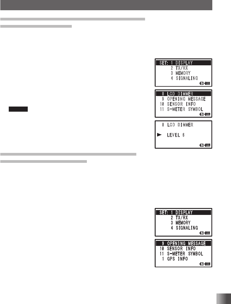
4 Turn O to select [8 LCD DIMMER].
5 Press H.
6 Turn O to select a brightness level.
You can select from LEVEL 1 (DARK) to LEVEL 6 (BRIGHT).
Remark Default: LEVEL 6
7 Press p to save the selected display brightness level, and
exit the Set mode.
Changing the Opening Message Displayed
Immediately after Power-on
You can select the message displayed under the “YAESU” logo from among four types:
“no message”, “power supply voltage”, “message comprising up to 16 characters”, and
“callsign”.
Enter the Set mode:
1 Press and hold M for over 1 second.
2 Turn O to select [1 DISPLAY].
3 Press H.
4 Turn O to select [9 OPENING MESSAGE].
5 Press H.
䎃 䎛 䎃 䎯 䎦 䎧 䎃 䎧 䎬 䎰䎰䎨䎵
䎃䎃䎃䎃䎃䎃䎯 䎨 䎹 䎨 䎯 䎃 䎙
䎃
䎶䎨䎷 䎝 䎃䎃䎔䎃 䎧 䎬 䎶 䎳䎯䎤䎼
䎃䎃䎃䎃䎃䎃䎃䎃䎕 䎃䎷 䎻 䎒 䎵 䎻
䎃䎃䎃䎃䎃䎃䫹䎃 䎖 䎃䎰䎨䎰䎲䎵䎼
䎃䎃䎃䎃䎃䎃䎃䎃䎗 䎃 䎶 䎬 䎪 䎱 䎤 䎯 䎬 䎱䎪
䎛䎃 䎯 䎦 䎧 䎃 䎧 䎬 䎰䎰䎨䎵
䎃䎜 䎃䎲䎳䎨 䎱 䎬 䎱䎪䎃䎰 䎨䎶䎶䎤䎪䎨
䎔䎓䎃䎶 䎨 䎱 䎶 䎲 䎵 䎃䎬 䎱 䎩䎲
䎔 䎔 䎃䎃䎶 䙵 䎰 䎨 䎷 䎨 䎵 䎃䎶䎼䎰䎥䎲䎯
Application for FCC / IC
FCC ID: K6620445X20
IC: 511B-20445X20
108
Functions Used As Needed
Set Mode
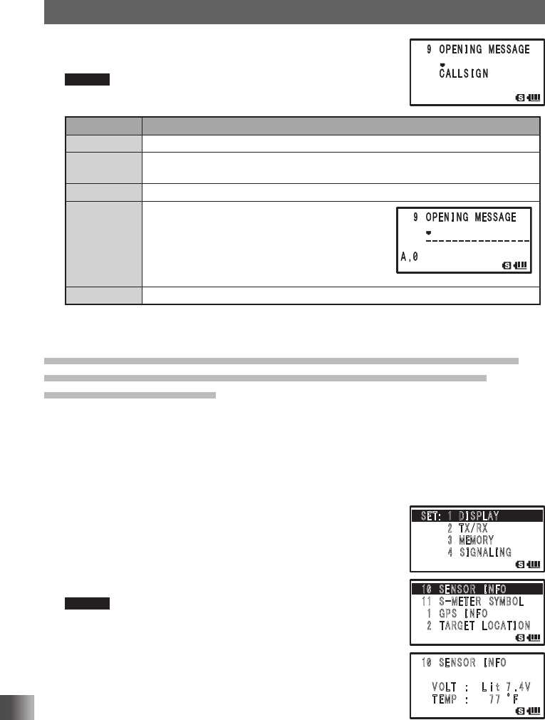
6 Turn O to select the display method.
Select a message type with reference to the following table:
Remark Default: CALLSIGN
Display Display Condition
NORMAL The YAESU logo appears immediately after power-on.
OFF Immediately after power-on, the reception frequency, etc. appear without display-
ing an opening message.
DC The power supply voltage and time appear immediately after power-on.
MESSAGE A message comprising up to 16 characters ap-
pears immediately after power-on.
Pressing H displays the message registration
screen. Enter a message to be displayed following
the procedure described in “Assigning a Name to a
Memory Channel” (See page 47).
CALLSIGN Your callsign appears immediately after power-on.
7 Press p to save the selected display method, and exit from the Set mode.
Measuring the Battery Voltage and the Transceiver Temperature
Power Supply Voltage Measurement Function/Temperature
Measurement Function
You can measure the battery voltage and the temperature inside the transceiver. When
the optional external power supply adapter with a cigarette plug (SDD-13) is connected,
the power supply voltage of this adapter is measured.
Enter the Set mode:
1 Press and hold M for over 1 second.
2 Turn O to select [1 DISPLAY].
3 Press H.
4 Turn O to select [10 SENSOR INFO].
5 Press H.
The voltage and temperature appear on the LCD.
Remark When the temperature appears on the LCD, pressing V
toggles the unit of temperature display between °C and °F.
7 Press M.
8 Press p to exit from the Set mode.
䎔 䎓 䎃 䎶 䎨 䎱 䎶 䎲 䎵 䎃 䎬 䎱 䎩䎲
䎃䎃䎃䎃 䎹 䎲 䎯䎷䫹䎝䎃䎃䎃䎃 䎯 䏌 䏗䎃䎃䎚 䎑 䎗 䎹
䎃䎃䎃䎃䎃䎷 䎨䎰䎳 䫹 䎝䎃䎃䎃䎃䎃 䎃 䎚 䎚 䫹 q䎩
䎃
䎶䎨䎷 䎝 䎃䎃䎔䎃 䎧 䎬 䎶 䎳䎯䎤䎼
䎃䎃䎃䎃䎃䎃䎃䎃䎕 䎃䎷 䎻 䎒 䎵 䎻
䎃䎃䎃䎃䎃䎃䫹䎃 䎖 䎃䎰䎨䎰䎲䎵䎼
䎃䎃䎃䎃䎃䎃䎃䎃䎗 䎃 䎶 䎬 䎪 䎱 䎤 䎯 䎬 䎱䎪
䎔 䎓 䎃 䎶 䎨 䎱 䎶 䎲 䎵 䎃 䎬 䎱 䎩䎲
䎔 䎔 䎃䎃䎶䙵 䎰 䎨䎷 䎨 䎵 䎃䎶䎼䎰䎥䎲䎯
䎃 䎔 䎃䎪 䎳 䎶 䎃 䎬 䎱 䎩 䎲
䎃 䎕 䎃䎷䎤䎵䎪 䎨 䎷 䎃䎯 䎲 䎦䎤䎷 䎬 䎲䎱
Application for FCC / IC
FCC ID: K6620445X20
IC: 511B-20445X20
109
Functions Used As Needed
Set Mode
Tips
• The display changes as follows depending on the type of the power supply used.
Battery pack: “Lit”
Battery case: “Dry”
External power supply adapter: “Ext”
• During mono band reception, the voltage can be displayed on the LCD constantly (See page 27).
• This function displays the temperature inside the transceiver.
• In a situation where the temperature inside of the transceiver does not rise (e.g., standby reception),
you can know the approximate outside temperature from the temperature displayed on the LCD.
Changing the Display Pattern of the PO Meter
You can select a display pattern of the S/PO meter from among four types.
Enter the Set mode:
1 Press and hold M for over 1 second.
2 Turn O to select [1 DISPLAY].
3 Press H.
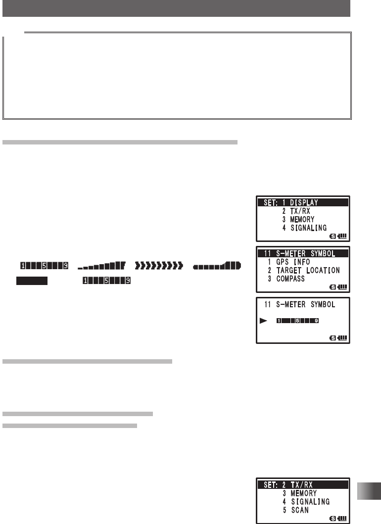
4 Turn O to select [11 S-METER SYMBOL].
5 Press H.
6 Turn O to select a display pattern.
///
Remark Default:
///
7 Press p to save the selected display pattern, and exit from
the Set mode.
Switching between AM Antennas
You can switch antennas when listening to AM broadcast stations.
For details, see “Switching between AM Antennas” on page 33.
Reducing receiver sensitivity
Attenuator (ATT) Function
If the signal from the remote station is too strong or, a strong signal is present nearby that
interferes with reception, use the attenuator (ATT) function.
Enter the Set mode:
1 Press and hold M for over 1 second.
2 Turn O to select [2 TX/RX].
3 Press H.
Application for FCC / IC
FCC ID: K6620445X20
IC: 511B-20445X20
110
Functions Used As Needed
Set Mode
4 Turn O to select [1 MODE].
5 Press H.
6 Turn O to select [2 ANTENNA ATT].
7 Press H.
8 Turn O to select [ON].
Remark Default: OFF
9 Press p to save the attenuator function setting, and exit
the Set mode.
Tip
• The amount of attenuation by the attenuator (ATT) is about 10 dB.
Setting the transmission modulation level
You can set the transmission modulation level to half of its usual level.
Set [OFF] for normal amateur operation.
Enter the Set mode:
1 Press and hold M for over 1 second.
2 Turn O to select [2 TX/RX].
3 Press H.
4 Turn O to select [1 MODE].
5 Press H.
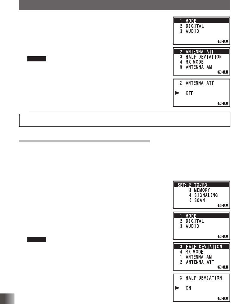
6 Turn O to select [3 HALF DEVIATION].
7 Press H.
8 Turn O to select [ON]
Remark Default: OFF
9 Press p to save the transmission modulation level is set,
and exit the Set mode.
Application for FCC / IC
FCC ID: K6620445X20
IC: 511B-20445X20
111
Functions Used As Needed
Set Mode
Changing the mode manually
Manually switch to an optimum mode (radio wave type) according to the frequency band.
For more details, see “Changing the Mode Manually” on page 38.
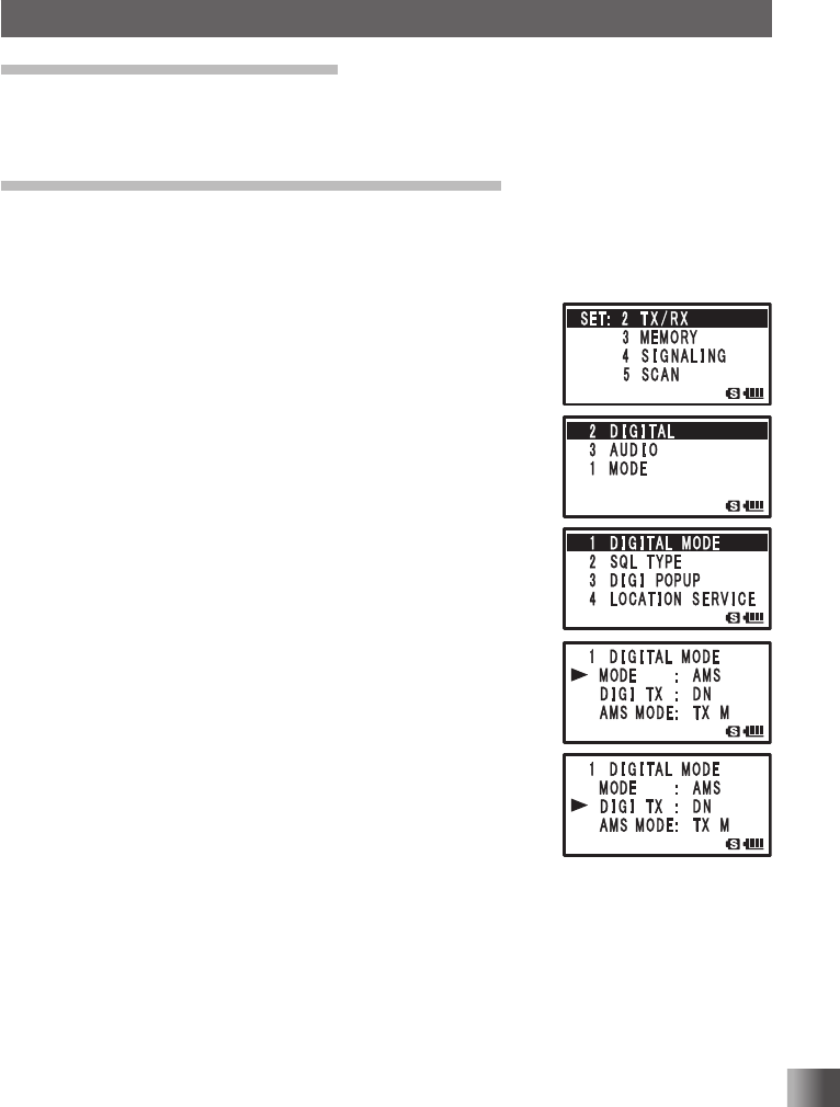
Switching between digital and analog mode
You can set digital and analog mode switching and digital transmission mode.
Enter the Set mode:
1 Press and hold M for over 1 second.
2 Turn O to select [2 TX/RX].
3 Press H.
4 Turn O to select [2 DIGITAL].
5 Press H.
6 Turn O to select [1 DIGITAL MODE].
7 Press H.
8 Turn O to select [MODE].
9 Press H.
10
Turn O to select your desired mode.
DIGITAL: Transmit and receive in the digital mode.
ANALOG: Transmit and receive in the analog mode.
AMS (Automatic Mode Select):
Tune to the transmission and reception mode of the remote
station from which a signal is automatically received.
11 Press M.
12
Turn O to select [DIGI TX].
13
Press H.
14
Turn O to select a reception mode.
DN: Usual digital communication mode. Conversation is
infrequently interrupted even under low power level.
VW: (Voice Wide) Full rate high quality sound mode This is the transmission function
to prioritize the sound quality when the communication condition of the remote
station is relatively good.
15
Press p to save the setting and exit the Set mode.
Application for FCC / IC
FCC ID: K6620445X20
IC: 511B-20445X20
112
Functions Used As Needed
Set Mode
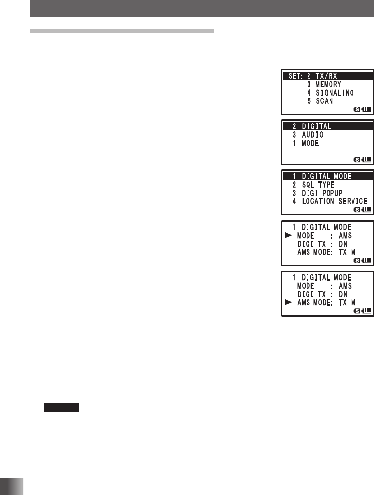
Setting the AMS transmission mode
When operating in the AMS function, the transmit mode may be selected:
1 Press and hold M for over 1 second.
2 Turn O to select [2 TX/RX].
3 Press H.
4 Turn O to select [2 DIGITAL].
5 Press H.
6 Turn O to select [1 DIGITAL MODE].
7 Press H.
8 Turn O to select [AMS MODE].
9 Press H.
10
Turn O to select the AMS transmit mode.
TX M: The operating mode is automatically selected
from four communication modes to match the
received signal. Pressing the Microphone [PTT]
momentarily, toggles between the Digital and
Analog communication modes.
TX FM: The RX mode is automatically selected from the
four communication modes to match the received
signal. The TX mode is automatically changed to
the “FM” mode.
TX DN: The RX mode is automatically selected from the
four communication modes to match the received
signal. The TX mode is automatically changed to
the “DN” mode.
TX VW: The RX mode is automatically selected from the four communication modes
to match the received signal. The TX mode is automatically changed to the
“VW” mode.
AUTO: The RX and TX operating mode is automatically selected from the four
communication modes to match the received signal.
Remarks • Default: TX M
• Blink “ ▎” : TX M
Blink “ ▎
OO” : TX FM / TX DN / TX VW
The OO symbol display differs according to the received signal.
11
Press p to save the setting and exit the Set mode.
Application for FCC / IC
FCC ID: K6620445X20
IC: 511B-20445X20
113
Functions Used As Needed
Set Mode
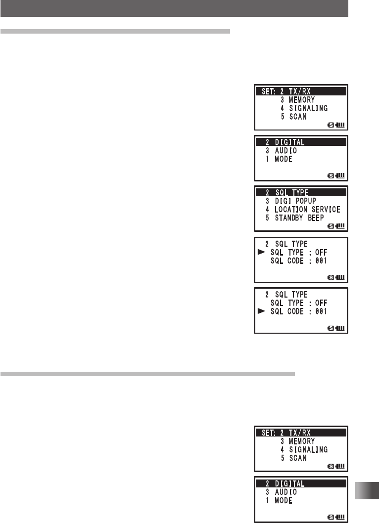
Setting the squelch type for the digital mode
You can set the squelch type for the digital mode.
Enter the Set mode:
1 Press and hold M for over 1 second.
2 Turn O to select [2 TX/RX].
3 Press H.
4 Turn O to select [2 DIGITAL].
5 Press H.
6 Turn O to select [2 SQL TYPE].
7 Press H.
8 Turn O to select [SQL TYPE].
9 Press H.
10
Turn O to select a squelch type.
OFF: Voice is always output upon receiving a digital signal
from a Yaesu transceiver.
CODE: Voice is output only when receiving a signal with a
corresponding SQL CODE.
BREAK: Voice is output regardless of any squelch code
when the remote station transmits with BREAK set.
11 Press M.
12
Turn O to select [SQL CODE].
13
Press H.
14
Turn O to enter a code.
You can enter SQL CODE of 126 types from 001 to 126.
15
Press p to save the SQL CODE setting and exit the Set mode.
Setting the pop up time of the remote station information
You can set the time duration to display the remote station information, such as callsign,
on the LCD.
Enter the Set mode:
1 Press and hold M for over 1 second.
2 Turn O to select [2 TX/RX].
3 Press H.
4 Turn O to select [2 DIGITAL].
5 Press H.
Application for FCC / IC
FCC ID: K6620445X20
IC: 511B-20445X20
114
Functions Used As Needed
Set Mode
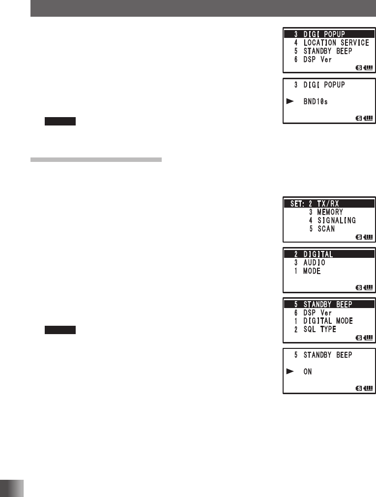
6 Turn O to select [3 DIGI POPUP].
7 Press H.
8 Turn O to select the display method.
OFF: Does not display the remote station information.
BND2s to 60s: Set the time to display the remote station
information (2 to 60 seconds).
BNDCNT: Always display the remote station information.
Remark Default: 10 seconds
9 Press p to save the pop up time setting and exit the Set mode.
Setting the Standby Beep
When communicating in a digital mode, a beep is sounded after the end of the other
stations transmission.
1 Press and hold M for over 1 second.
2 Turn O to select [2 TX/RX].
3 Press H.
4 Turn O to select [2 DIGITAL].
5 Press H.
6 Turn O to select [5 STANDBY BEEP].
7 Press H.
8 Turn O to select [OFF]/[ON].
OFF: Disable the STANDBY BEEP feature.
ON: Enable the STANDBY BEEP feature.
Remark Default: ON
9 Press p to exit from the Set mode.
Application for FCC / IC
FCC ID: K6620445X20
IC: 511B-20445X20
115
Functions Used As Needed
Set Mode
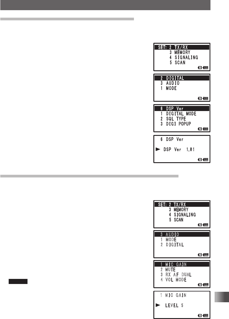
Displaying the version of the DSP program
You can check the DSP program version of the built in digital unit of the transceiver.
First enter the digital mode, and then enter the Set mode:
1 Press and hold M for over 1 second.
2 Turn O to select [2 TX/RX].
3 Press H.
4 Turn O to select [2 DIGITAL].
5 Press H.
6 Turn O to select [6 DSP Ver].
7 Press H.
The version of the DSP program appears on the LCD.
8 Press p to exit from the Set mode.
Adjusting the microphone sensitivity Microphone Gain
You can adjust the input level of the built-in microphone or an optional external microphone.
Enter the Set mode:
1 Press and hold M for over 1 second.
2 Turn O to select [2 TX/RX].
3 Press H.
4 Turn O to select [3 AUDIO].
5 Press H.
6 Turn O to select [1 MIC GAIN].
7 Press H.
8 Turn O to select a microphone sensitivity level.
Select a microphone gain level from the following:
LEVEL 1 (Lowest sensitivity) to LEVEL 9 (Highest sensitivity)
Remark Default: LEVEL 5
9 Press M twice.
The selected microphone gain level is set.
䎶䎨䎷䎝䎃䎃䎕 䎃 䎷 䎻 䎒 䎵 䎻
䎃䎃䎃䎃䎃䎃䎃䎃䎖 䎃䎰䎨䎰䎲䎵䎼
䎃䎃䎃䎃䎃䎃䎃䎃䎗 䎃 䎶 䎬 䎪 䎱 䎤 䎯 䎬 䎱䎪
䎃䎃䎃䎃䎃䎃䎃䎃䎘 䎃 䎶䎦䎤䎱
䎖 䎃 䎤 䎸 䎧 䎬 䎲
䎔䎃䎰䎲䎧䎨
䎃 䎕 䎃䎧 䎬 䎪 䎬 䎷 䎤 䎯
䎔 䎃 䎰 䎬 䎦䎃䎃䎪 䎤 䎬 䎱
䎕䎃䎰䎸䎷 䎨
䎃 䎖 䎃䎵 䎻 䎃䎤 䎩 䎃 䎧䎸䎤䎯
䎃䎗䎃䎃䎹䎲䎯 䎃 䎰 䎲 䎧 䎨
䎃 䎔 䎃 䎰 䎬 䎦 䎃 䎪 䎤 䎬 䎱
䎃䎃䎃䎃䎃䎃䎯 䎨 䎹 䎨 䎯 䎃 䎘
Application for FCC / IC
FCC ID: K6620445X20
IC: 511B-20445X20
116
Functions Used As Needed
Set Mode
10
Press p to exit the Set mode.
Tips
• Increasing the microphone gain excessively can distort the sound or pick up the surrounding noise,
impairing intelligibility.
• Be sure to adjust the microphone gain whenever you change microphones.
Muting Voice
In the dual reception mode, the audio being received on the non-operating band is muted
when a signal is herd on the operating band.
For more details, see “Muting Audio” on page 35.
Simultaneously radio broadcast reception
Set the mute time of the simultaneous broadcast reception.
For more details, see “AF-DUAL Function” for simultaneously monitoring the amateur
frequency while listening to the broadcast radio.
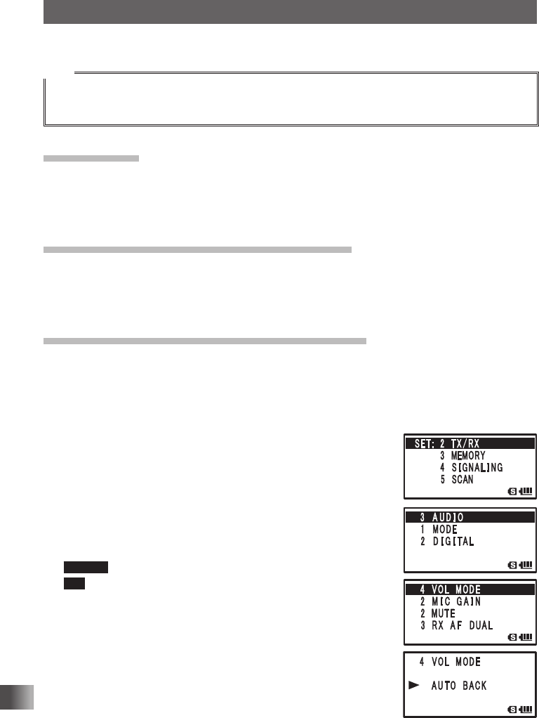
Changing the sound volume setting method
You can set the sound volume adjustment mode to be automatically canceled after about
3 seconds, after pressing v and then adjusting the sound volume with O.
Enter the Set mode:
1 Press and hold M for over 1 second.
2 Turn O to select [2 TX/RX].
3 Press H.
4 Turn O to select [3 AUDIO].
5 Press H.
6 Turn O to select [4 VOL MODE].
7 Press H.
8 Turn O to select [AUTO BACK].
Remark Default: NORMAL
Tip Usually adjust the sound volume by turning O while pressing
v. If the [AUTO BACK] is selected, the sound volume
adjustment mode will be automatically canceled after you have
pressed v to enter the sound volume adjustment mode and
return to the frequency display screen.
9 Press p to exit the Set mode.
Application for FCC / IC
FCC ID: K6620445X20
IC: 511B-20445X20
117
Functions Used As Needed
Set Mode
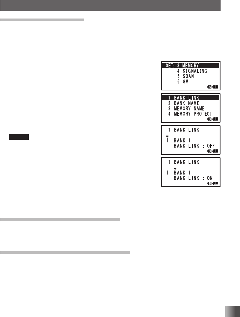
Setting memory bank link
You can link multiple registered memory banks, and also recall a frequently used memory
bank immediately
Enter the Set mode:
1 Press and hold M for over 1 second.
2 Turn O to select [3 MEMORY].
3 Press H.
4 Turn O to select [1 BANK LINK].
5 Press H.
6 Turn O to select a memory bank to link.
7 Press B.
The cursor moves to the position (such as BANK1) to set
link.
8 Turn O to select [ON].
Remark Default: OFF
9 Press B.
10
Also set link to other memory banks.
Set link to each memory bank from memory bank 1 through
memory bank 24 by repeating step 6 to 9.
11 Press H.
The memory bank link is set.
12
Press p.
Exits from the Set mode.
Assigning a name to a memory bank
A memory bank can be assigned a name with up to 16 characters.
For more details, see “Assigning Name to Memory Bank” on page 49.
Assigning a name to a memory channel
Memory channels and home channels may be assigned a name (memory tag) such as a
callsign or broadcast station name.
For more details, see “Using Memory Tag” on page 46.
Application for FCC / IC
FCC ID: K6620445X20
IC: 511B-20445X20
118
Functions Used As Needed
Set Mode
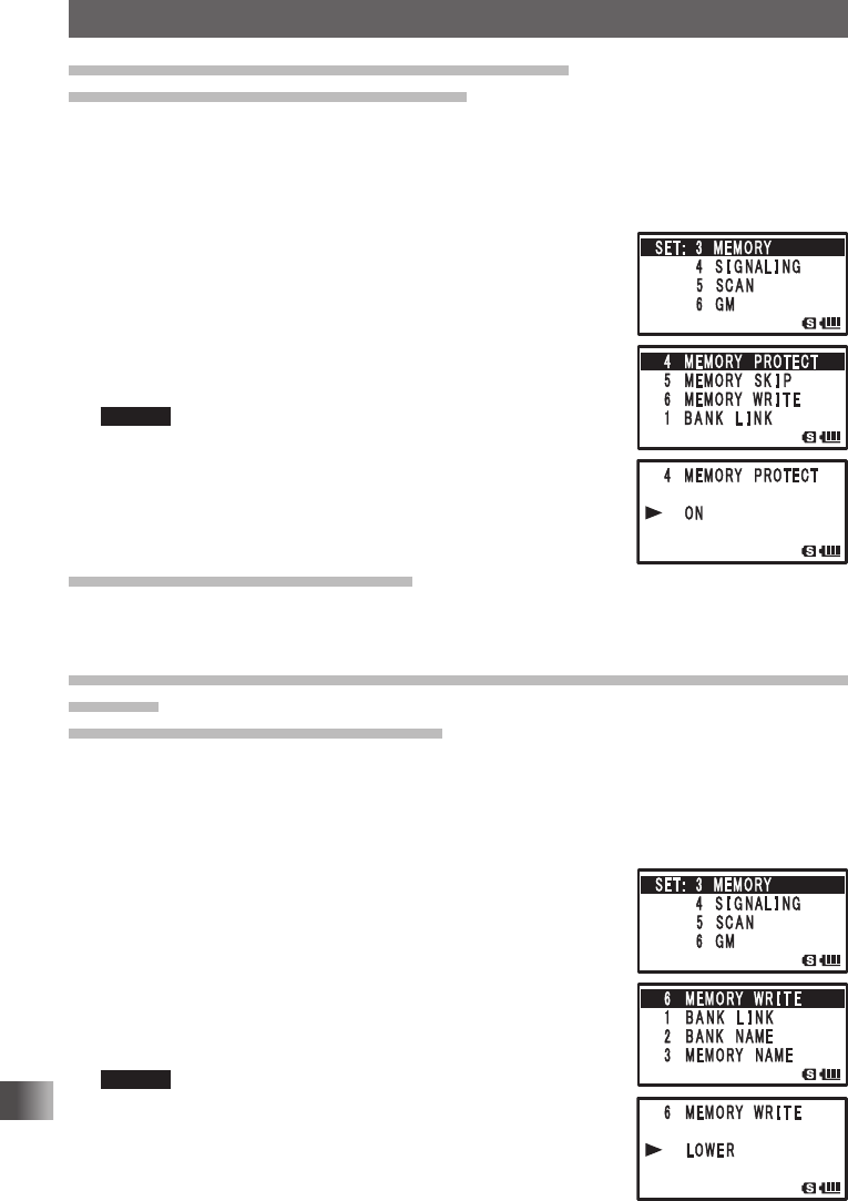
Prohibiting registration to memory channel
Memory Channel Protect Function
A memory channel may be protected so that a new frequency or memory channel tag
name cannot be registered to it.
Enter the Set mode:
1 Press and hold M for over 1 second.
2 Turn O to select [3 MEMORY].
3 Press H.
4 Turn O to select [4 MEMORY PROTECT].
5 Press H.
6 Turn O to select [ON].
Any registration to the memory channel is prohibited.
Remark Default: OFF
7 Press p to save the memory channel protect, and exit the
Set mode.
Setting memory skip function
Set the scan method for scanning memory channels.
For more details, see “Specifying a Skip/Selected Memory Channel” on page 60.
Registering to a memory channel with the lowest memory channel
number
Memory Channel Write Function
When registering to a memory channel. you can display an unregistered memory channel
with the lowest memory channel number.
Enter the Set mode:
1 Press and hold M for over 1 second.
2 Turn O to select [3 MEMORY].
3 Press H.
4 Turn O to select [6 MEMORY WRITE].
5 Press H.
6 Turn O to select [LOWER].
A memory channel with the lowest memory channel number
appears on the LCD.
Remark Default: NEXT
7 Press p to set the memory channel registration to the
lowest unregistered memory channel number, and exit from
the Set mode.
Application for FCC / IC
FCC ID: K6620445X20
IC: 511B-20445X20
119
Functions Used As Needed
Set Mode
Notifying a call from a remote station by the bell
Notifies you of a call from a remote station by the bell.
See “Notification of a Call from a Remote Station by the Bell” on page 89.
Selecting a DCS code
Select the DCS code from 104 codes from 023 to 754.
For more details, see “Setting a DCS Code” on page 86.
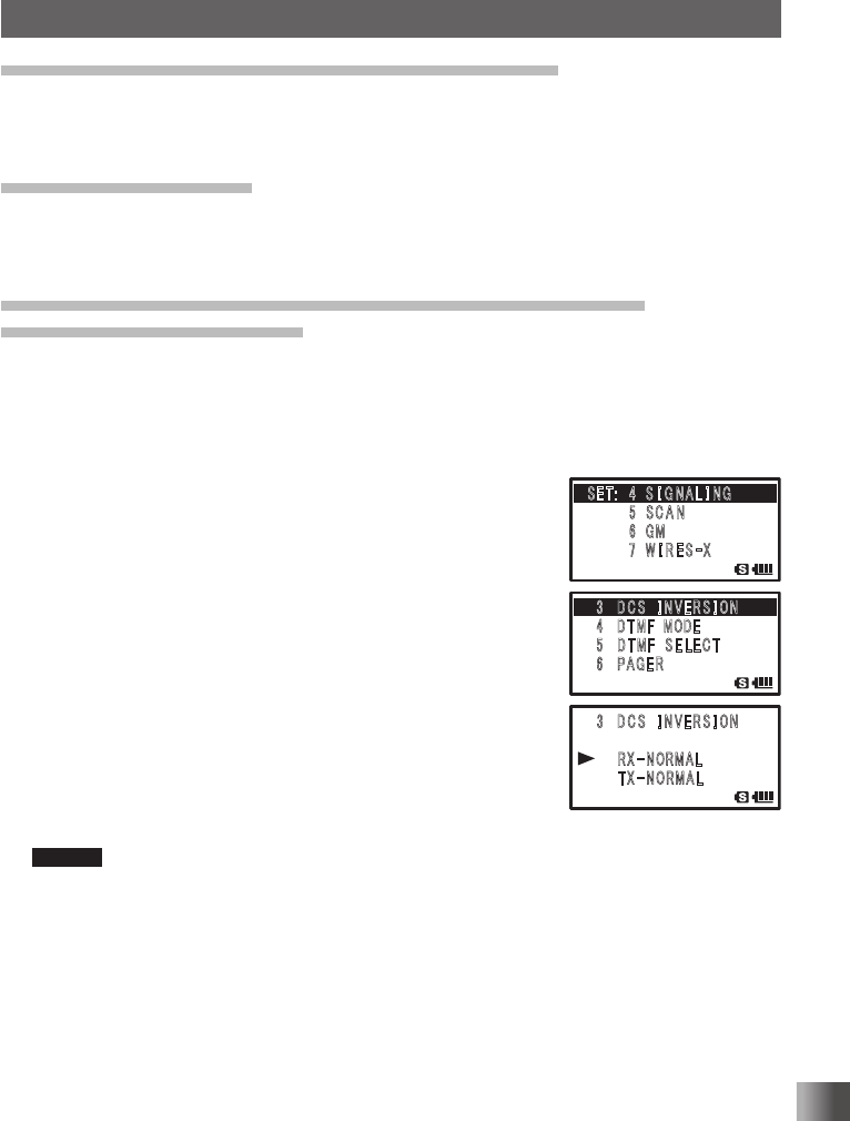
Transmit and receive a DCS Code with a inverted phase
DCS INVERSION Function
You can transmit and receive a DCS code with an inverted phase when using the digital
code squelch function.
Enter the Set mode:
1 Press and hold M for over 1 second.
2 Turn O to select [4 SIGNALING].
3 Press H.
4 Turn O to select [3 DCS INVERSION].
5 Press H.
6 Turn O to select a phase.
When a phase is selected for the reception side, the phase
for transmission side is automatically determined.
Reception: [Homeomorphic], [Both Phase],
[Inverted Phase], [Homeomorphic],
[Both Phase], [Inverted Phase]
Transmission: [Homeomorphic], [Inverted Phase],
[Inverted Phase], [Inverted Phase],
[Homeomorphic], [Homeomorphic]
Remark Default: Reception [Homeomorphic], Transmission [Homeomorphic]
7 Press p.
The phase of DCS code is set, and exits from the Set mode.
䎖䎃䎃 䎧 䎦 䎶䎃䎃 䎬 䎱 䎹 䎨 䎵 䎶 䎬 䎲䎱
䎗䎃䎃 䎧 䎷 䎰䎩䎃 䎃䎰䎲 䎧 䎨
䎘 䫹 䎧 䎷 䎰䎩䎃 䎃䎶 䎨 䎯 䎨 䎦 䎷
䎙 䫹 䎳 䎤 䎪 䎨 䎵
䎃 䎖 䎃 䎧 䎦 䎶䎃䎃 䎬 䎱 䎹 䎨 䎵 䎶 䎬 䎲䎱
䎃䎃䎃䎃䎃䎃 䎵 䎻
䙵
䎱 䎲䎵䎰䎤䎯
䎃䎃䎃䎃䎃䎃䎃䎷 䎻
䙵
䎱 䎲䎵䎰䎤䎯
䎶䎨䎷䎝䎃䎃䎗䎃 䎶 䎬 䎪 䎱 䎤 䎯 䎬 䎱䎪
䎃䎃䎃䎃䎃䎃䎃䎃䎘 䎃䎶 䎦 䎤 䎱
䎃䎃䎃䎃䎃䎃䫹䎙 䎃䎪䎰
䎃䎃䎃䎃䎃䎃䎃䎃䎚 䎃 䎺 䎬 䎵 䎨 䎶
䙵
䎻
䎖䎃䎃 䎧 䎦 䎶䎃䎃 䎬 䎱 䎹 䎨 䎵 䎶 䎬 䎲䎱
䎗䎃䎃 䎧 䎷 䎰䎩䎃 䎃䎰䎲 䎧 䎨
䎘 䫹 䎧 䎷 䎰䎩䎃 䎃䎶 䎨 䎯 䎨 䎦 䎷
䎙 䫹 䎳 䎤 䎪 䎨 䎵
䎃 䎖 䎃 䎧 䎦 䎶䎃䎃 䎬 䎱 䎹 䎨 䎵 䎶 䎬 䎲䎱
䎃䎃䎃䎃䎃䎃 䎵 䎻
䙵
䎱 䎲䎵䎰䎤䎯
䎃䎃䎃䎃䎃䎃䎃䎷 䎻
䙵
䎱 䎲䎵䎰䎤䎯
䎶䎨䎷䎝䎃䎃䎗䎃 䎶 䎬 䎪 䎱 䎤 䎯 䎬 䎱䎪
䎃䎃䎃䎃䎃䎃䎃䎃䎘 䎃䎶 䎦 䎤 䎱
䎃䎃䎃䎃䎃䎃䫹䎙 䎃䎪䎰
䎃䎃䎃䎃䎃䎃䎃䎃䎚 䎃 䎺 䎬 䎵 䎨 䎶
䙵
䎻
Application for FCC / IC
FCC ID: K6620445X20
IC: 511B-20445X20
120
Functions Used As Needed
Set Mode
Setting the transmission method of the DTMF code
Set the transmission method of the registered DTMF code.
For more details, see “Sending the Registered DTMF Code” on page 80.
Setting DTMF code
The maximum of 16 digit DTMF code can be registered for a telephone number to make
a call through the public telephone line from a phone patch.
For more details, see “Using DTMF Function” on page 79.
Calling only a specific station
New Pager Function
When using transceivers with your friends, specifying personal codes allows only a
specific station to be called.
For more details, see “Calling Only a Specific Station New Pager Function” on page 90.
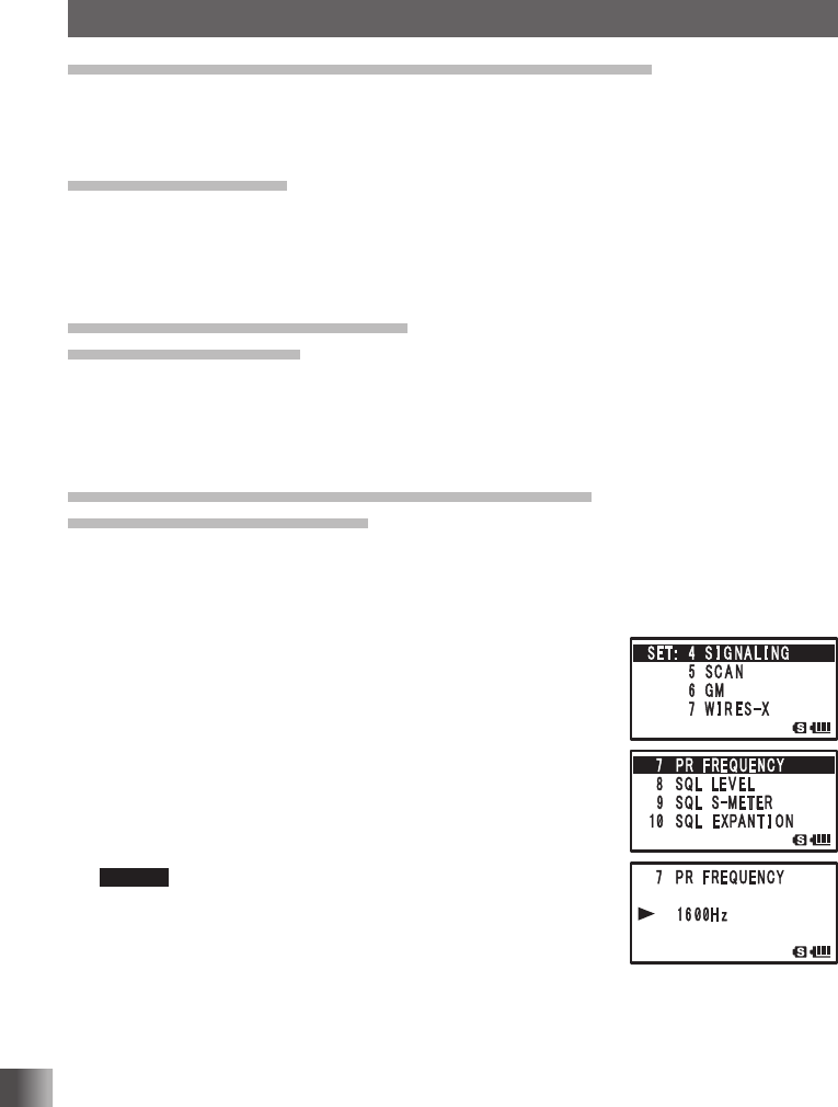
Enabling no-communication squelch function
PR FREQUENCY Function
You can set a no-communication squelch frequency in steps of 100 Hz within the range
from 300 Hz to 3000 Hz.
Enter the Set mode:
1 Press and hold M for over 1 second.
2 Turn O to select [4 SIGNALING].
3 Press H.
4 Turn O to select [7 PR FREQUENCY].
5 Press H.
6 Turn O to tune in to a frequency.
Select no-communication squelch frequency in steps of 100
Hz.
Remark Default: 1600 Hz
7 Press p to set the no-communication squelch function,
and exit the Set mode.
Application for FCC / IC
FCC ID: K6620445X20
IC: 511B-20445X20
121
Functions Used As Needed
Set Mode
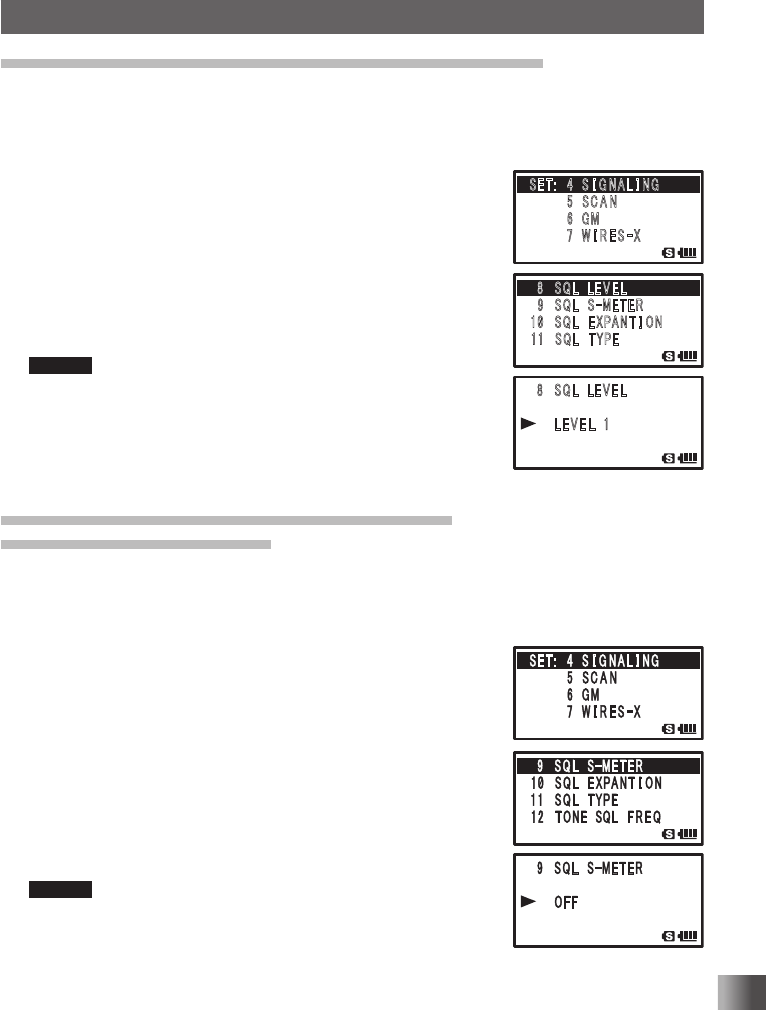
Adjusting the squelch level SQL LEVEL Function
You can set squelch level to mute the raspy noise heard.
Enter the Set mode:
1 Press and hold M for over 1 second.
2 Turn O to select [4 SIGNALING].
3 Press H.
4 Turn O to select [8 SQL LEVEL].
5 Press H.
6 Turn O to select a squelch level.
Select from among LEVEL 0 to LEVEL 15.
The higher the squelch level, the greater the noise reduction.
Remark Default: LEVEL 1
7 Press p to save the selected squelch type, and exit the Set
mode.
Setting the signal strength to output sound
S Meter Squelch Function
You can set A-Band and B-Band individually to output the sound only when receiving a
signal stronger than signal strength level set to the S-Meter Level.
1 Select a band as an operating band.
2 Press and hold M for over 1 second to enter the Set
mode.
3 Turn O to select [4 SIGNALING].
4 Press H.
5 Turn O to select [9 SQL S-METER].
6 Press H.
7 Turn O to select a setting value.
Select a S-Meter level with reference to the table shown
below.
Remark Default: OFF
8 Press p to save the selected S-Meter level, and exit the
Set mode.
䎛 䎃 䎶䎴䎯䎃䎃䎯 䎨 䎹 䎨 䎯
䎜䎃䎶䎴䎯 䎃 䎶
䙵
䎰䎨䎷䎨䎵
䎔䎓䎃䎶䎴䎯䎃䎃䎨 䎻䎳䎤䎱䎷 䎬 䎲䎱
䎔䎔䎃䎶䎴䎯䎃䎃䎷 䎼 䎳䎨
䎃 䎛 䎃 䎶 䎴䎯䎃䎃䎯 䎨 䎹 䎨 䎯
䎃䎃䎃䎃 䎯 䎨 䎹 䎨 䎯 䎃 䎔
䎃
䎶䎨䎷䎝䎃䎃䎗䎃 䎶 䎬 䎪 䎱 䎤 䎯 䎬 䎱䎪
䎃䎃䎃䎃䎃䎃䎃䎃䎘 䎃䎶 䎦 䎤 䎱
䎃䎃䎃䎃䎃䎃䫹䎙 䎃䎪䎰
䎃䎃䎃䎃䎃䎃䎃䎃䎚 䎃 䎺 䎬 䎵 䎨 䎶
䙵
䎻
Application for FCC / IC
FCC ID: K6620445X20
IC: 511B-20445X20
122
Functions Used As Needed
Set Mode
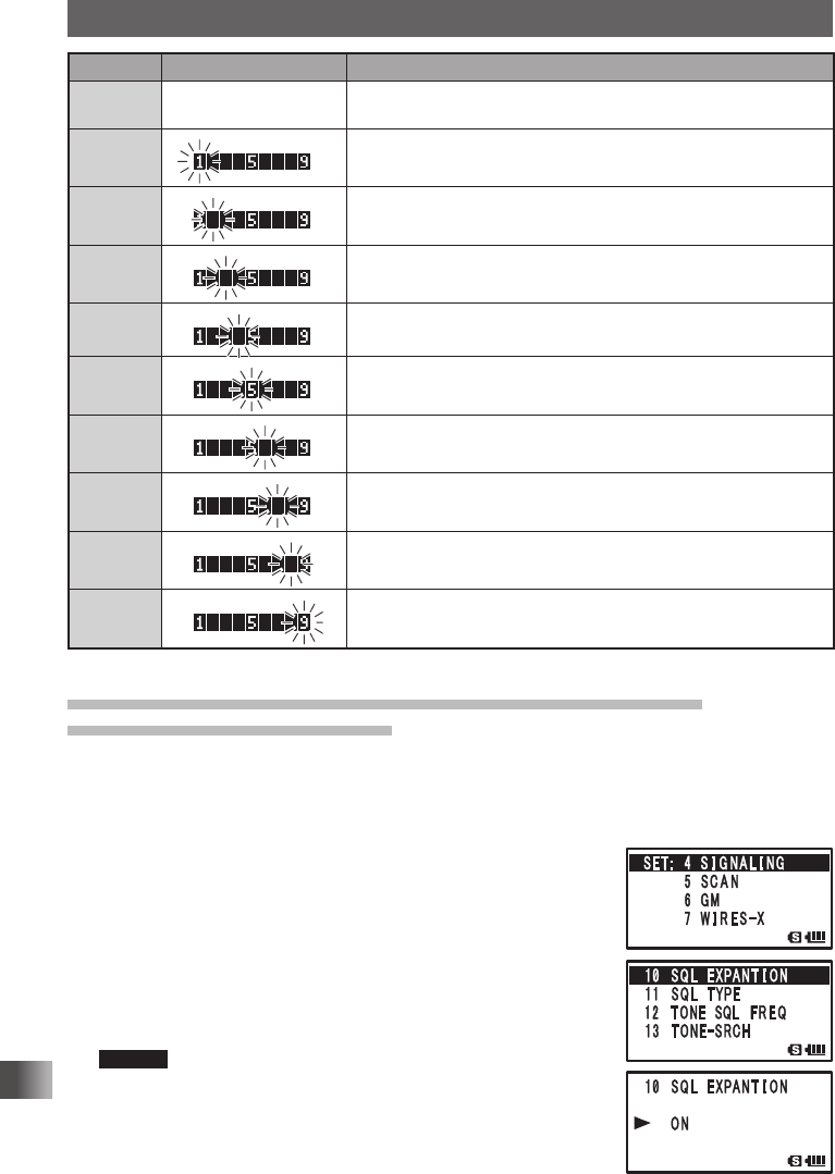
Display S-Meter Display Operating Status
OFF No display S-Meter squelch function is OFF.
(By default, S-Meter squelch function is set to OFF.)
Level 1 Outputs the sound of signal stronger than the S-Meter level 1.
Level 2 Outputs the sound of signal stronger than the S-Meter level 2.
Level 3 Outputs the sound of signal stronger than the S-Meter level 3.
Level 4 Outputs the sound of signal stronger than the S-Meter level 4.
Level 5 Outputs the sound of signal stronger than the S-Meter level 5.
Level 6 Outputs the sound of signal stronger than the S-Meter level 6.
Level 7 Outputs the sound of signal stronger than the S-Meter level 7.
Level 8 Outputs the sound of signal stronger than the S-Meter level 8.
Level 9 Outputs the sound of signal stronger than the S-Meter level 9.
Setting the squelch type for transmission and reception
SQL EXPANTION FUNCTION
Squelch types set beforehand can function separately for transmission and reception.
Enter the Set mode:
1 Press and hold M for over 1 second.
2 Turn O to select [4 SIGNALING].
3 Press H.
4 Turn O to select [10 SQL EXPANTION].
5 Press H.
6 Turn O to select [ON].
ON: Use separate squelch for transmission and reception.
OFF: Use the same squelch for transmission and reception.
Remark Default: OFF
7 Press p to save the separate squelch setting, and exit the
Set mode.
Application for FCC / IC
FCC ID: K6620445X20
IC: 511B-20445X20
123
Functions Used As Needed
Set Mode
Setting the type of tone squelch
Set the tone squelch to open the squelch only when a signal containing the specified
frequency tone is received.
For more details, see “Using the Tone Squelch Function” on page 84.
Selecting a tone frequency
Select the tone frequency from 50 types between 67.0 MHz and 254.1 MHz.
For more details, see “Setting a Tone Frequency” on page 85.
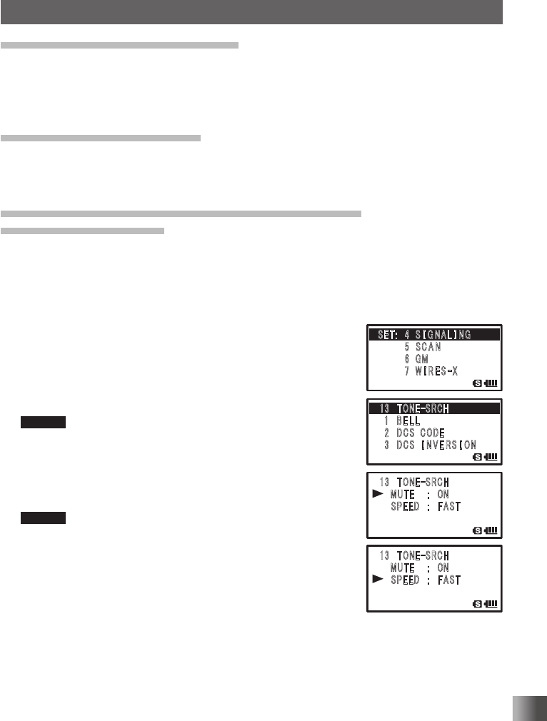
Setting the sound and speed during tone search
Tone Search Function
Sound can be muted during tone search. The operation speed of the tone search can
also be changed.
Enter the Set mode:
1 Press and hold M for over 1 second.
2 Turn O to select [4 SIGNALING].
3 Press H.
4 Turn O to select [13 TONE-SRCH].
5 Press H twice.
6 Turn O to select MUTE to [ON].
Remark Default: ON
7 Press M.
8 Turn O to select [SPPED].
9 Press H.
10
Turn O to select SPEED to [Rapid].
Remark Default: FAST
11
Press p to save the Tone Search setting and exit the Set
mode.
䎔䎖䎃 䎷 䎲 䎱 䎨
䙵
䎶 䎵 䎦 䎫
䎃䎔䎃䎃 䎥 䎨 䎯 䎯
䎃䎕䎃䎃䎧䎦䎶䎃䎃䎦䎲䎧䎨
䎃 䎖 䫹 䎧䎦䎶䎃䎃䎬 䎱 䎹 䎨 䎵 䎶 䎬 䎲䎱
䎔䎖䎃 䎷 䎲 䎱 䎨
䙵
䎶 䎵 䎦 䎫
䎃 䎃䎃 䎰䎸䎷䎨䎃䎃䎃䎝䎃䎃 䎲䎱
䎃 䎃 䎃 䎶䎳䎨䎨䎧䎃䎃䎃䎝䎃䎃 䎩 䎤䎶䎷
䎔䎖䎃 䎷 䎲 䎱 䎨
䙵
䎶 䎵 䎦 䎫
䎃 䎃䎃 䎰䎸䎷䎨䎃䎃䎃䎝䎃䎃 䎲䎱
䎃 䎃 䎃 䎶䎳䎨䎨䎧䎃䎃䎃䎝䎃䎃 䎩 䎤䎶䎷
䎶䎨䎷䎝䎃䎃䎗䎃 䎶 䎬 䎪 䎱 䎤 䎯 䎬 䎱䎪
䎃䎃䎃䎃䎃䎃䎃䎃䎘 䎃䎶 䎦 䎤 䎱
䎃䎃䎃䎃䎃䎃䫹䎙 䎃䎪䎰
䎃䎃䎃䎃䎃䎃䎃䎃䎚 䎃 䎺 䎬 䎵 䎨 䎶
䙵
䎻
䎔䎖䎃 䎷 䎲 䎱 䎨
䙵
䎶 䎵 䎦 䎫
䎃䎔䎃䎃 䎥 䎨 䎯 䎯
䎃䎕䎃䎃䎧䎦䎶䎃䎃䎦䎲䎧䎨
䎃 䎖 䫹 䎧䎦䎶䎃䎃䎬 䎱 䎹 䎨 䎵 䎶 䎬 䎲䎱
䎔䎖䎃 䎷 䎲 䎱 䎨
䙵
䎶 䎵 䎦 䎫
䎃 䎃䎃 䎰䎸䎷䎨䎃䎃䎃䎝䎃䎃 䎲䎱
䎃 䎃 䎃 䎶䎳䎨䎨䎧䎃䎃䎃䎝䎃䎃 䎩 䎤䎶䎷
䎔䎖䎃 䎷 䎲 䎱 䎨
䙵
䎶 䎵 䎦 䎫
䎃 䎃䎃 䎰䎸䎷䎨䎃䎃䎃䎝䎃䎃 䎲䎱
䎃 䎃 䎃 䎶䎳䎨䎨䎧䎃䎃䎃䎝䎃䎃 䎩 䎤䎶䎷
䎶䎨䎷䎝䎃䎃䎗䎃 䎶 䎬 䎪 䎱 䎤 䎯 䎬 䎱䎪
䎃䎃䎃䎃䎃䎃䎃䎃䎘 䎃䎶 䎦 䎤 䎱
䎃䎃䎃䎃䎃䎃䫹䎙 䎃䎪䎰
䎃䎃䎃䎃䎃䎃䎃䎃䎚 䎃 䎺 䎬 䎵 䎨 䎶
䙵
䎻
Application for FCC / IC
FCC ID: K6620445X20
IC: 511B-20445X20
124
Functions Used As Needed
Set Mode
ON/OFF for the Weather Alert Feature
Setting the Weather Alert Feature, used for notifying storms and hurricanes, ON or OFF.
Enter the Set mode:
1 Press and hold M for over 1 second.
2 Turn O to select [4 SIGNALING].
3 Press H.
4 Turn O to select [14 WX ALERT].
5 Press H.
6 Turn O to select [ON].
ON: Enables the Weather Alert Feature.
OFF: Disables the Weather Alert Feature.
Remark Default: OFF
7 Press p to save the Weather Alert ON or OFF setting, and exit the Set mode
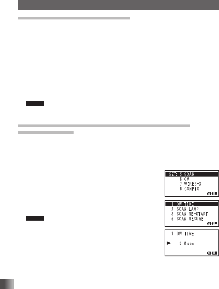
Setting the surveillance interval time for priority channels
DW TIME Function
When the dual reception function is active, the interval for monitoring the signal of the
priority channel can be set.
Enter the Set mode:
1 Press and hold M for over 1 second.
2 Turn O to select [5 SCAN].
3 Press H.
4 Turn O to select [1 DW TIME].
5 Press H.
6 Turn O to select the monitoring interval.
Interval can be selected from 0.1 SEC to 10 SEC.
Remark Default: 5 seconds
7 Press p to save the priority memory channel monitoring
interval setting and exit the Set mode.
䎔 䎃 䎧䎺䎃 䎃䎷 䎬 䎰 䎨
䎃䎃䎃䎃 䎃 䎘 䎑 䎓
䏖䏈䏆
䎃
䎶䎨䎷䎝䎃䎃䎘䎃 䎶 䎦 䎤 䎱
䎃䎃䎃䎃䎃䎃䎃䎃䎙 䎃䎪䎰
䎃䎃䎃䎃䎃䎃䫹䎚 䎃䎺 䎬 䎵 䎨 䎶
䙵
䎻
䎃䎃䎃䎃䎃䎃䎃䎃䎛 䎃 䎦䎲䎱 䎩 䎬 䎪
䎔 䎃 䎧䎺䎃 䎃䎷 䎬 䎰 䎨
䎕䎃䎶䎦䎤䎱䎃 䎃䎯 䎤䎰䎳
䎃䎖 䎃䎶䎦䎤䎱䎃 䎃䎵 䎨
䙵
䎶 䎷 䎤 䎵 䎷
䎃 䎗 䎃 䎶䎦䎤䎱䎃 䎃䎵 䎨䎶䎸䎰䎨
䎔 䎃 䎧䎺䎃 䎃䎷 䎬 䎰䎨
䎃䎃䎃䎃 䎃 䎘 䎑 䎓
䏖䏈䏆
䎃
䎶䎨䎷䎝䎃䎃䎘䎃 䎶 䎦 䎤 䎱
䎃䎃䎃䎃䎃䎃䎃䎃䎙 䎃䎪䎰
䎃䎃䎃䎃䎃䎃䫹䎚 䎃䎺 䎬 䎵 䎨 䎶
䙵
䎻
䎃䎃䎃䎃䎃䎃䎃䎃䎛 䎃 䎦䎲䎱 䎩 䎬 䎪
䎔 䎃 䎧䎺䎃 䎃䎷 䎬 䎰 䎨
䎕䎃䎶䎦䎤䎱䎃 䎃䎯 䎤䎰䎳
䎃䎖 䎃䎶䎦䎤䎱䎃 䎃䎵 䎨
䙵
䎶 䎷 䎤 䎵 䎷
䎃 䎗 䎃 䎶䎦䎤䎱䎃 䎃䎵 䎨䎶䎸䎰䎨
Application for FCC / IC
FCC ID: K6620445X20
IC: 511B-20445X20