Yaesu Musen 20445X20 AMATEUR RADIO WITH SCANNING RECEIVER User Manual 3
Yaesu Musen Co., Ltd. AMATEUR RADIO WITH SCANNING RECEIVER 3
Contents
User Manual 3
15
Basic Operation
Basic Operation
Preparation
Installing the Antenna
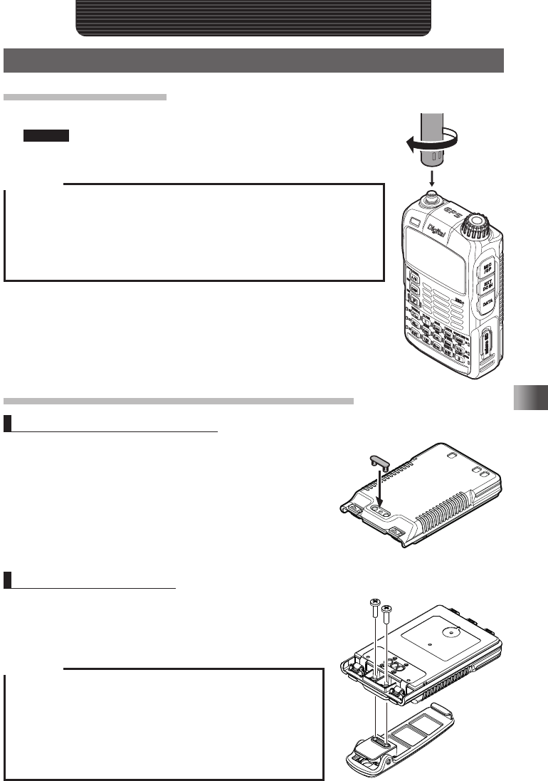
1 Align the antenna with the antenna terminal on the transceiver.
Caution Be sure to hold the thick base of the antenna when installing it.
2 Turn the antenna clockwise until it is secured.
Cautions
Do not hold the upper part of the antenna when installing or removing it.
To do so, the wire inside the antenna may break.
Do not transmit without installing the antenna. The transmitter circuit can
be damaged.
When using an antenna other than the accessory or any other external
antenna, ensure that its SWR is adjusted to 1.5 or lower.
Attaching the Accessory Belt Clip/Protective Cap
Attaching the Protective Cap
1 Attach the protective cap
If you do not use the belt clip, attach the protective cap
to the belt clip attaching screw holes on the battery
pack.
Attaching the Belt Clip
1 Turn over the battery pack.
2 Attach the belt clip to the battery pack using the sup-
plied screws (two).
Cautions
Be sure to use the supplied screws when attaching the
belt clip. If any other screws are used. the belt clip cannot
be secured firmly to the battery pack and the transceiver
may drop off together with the battery pack, causing injury,
breakage and other troubles.
Be sure to attach the protective cap when the belt clip is not
used.
Application for FCC / IC
FCC ID: K6620445X20
IC: 511B-20445X20
16
Basic Operation
Preparation
Attaching a Hand Strap
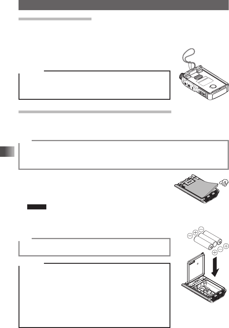
If you attach a hand strap to the transceiver, its string which is inserted in and secured to
the strap hole of the transceiver must have a diameter of 1 mm.
* The hand strap is not an accessory.
1 Remove the battery pack.
2 Attach the hand strap.
Cautions
Use a hand strap which can withstand the weight of the transceiver. If
you use a hand strap which is not strong enough, the hand strap can
break and the transceiver fall down, causing injury, breakage and other
troubles.
How to Use the Battery Case (FBA-39) Optional
The optional battery case (FBA-39) allows three (size) AA Alkaline batteries to be used
for the power supply.
Tips
When the battery case (FBA-39) is used, you can select a power output level from:
Low Power (L1): 0.1W
Low Power (L2): Approximately 0.8W
Note that Low Power (L3) and High Power are not available.
1 Open the cover.
Lift up the lower right corner indicated by the hand pointer in
the illustration.
2 Put alkaline batteries in the battery case.
Caution Use three alkaline batteries. Pay attention to polarities (+ and
–) of the alkaline batteries.
3 Close the cover.
Push the four corners of the cover firmly to close it tightly.
Tips
• When the battery charge is low, _ lights on the LCD. When the bat-
teries are almost exhausted, _ blinks on the LCD.
Cautions
Manganese batteries cannot be used. Rechargeable AA batteries
cannot be used, either.
Do not mix new and old batteries. The service life of new batteries
may decrease.
If you do not use the transceiver for a long period, remove the batter-
ies from the battery case.
If the terminal or electrode of the battery case is dirty, the transceiver
can malfunction due to poor contact, resulting in overheating or explo-
sion. If the terminal or electrode gets dirty, clean it using a dry cloth or
cotton swab.
Application for FCC / IC
FCC ID: K6620445X20
IC: 511B-20445X20
17
Basic Operation
Preparation
Installing/Removing the Battery Pack
Installing the Battery Pack
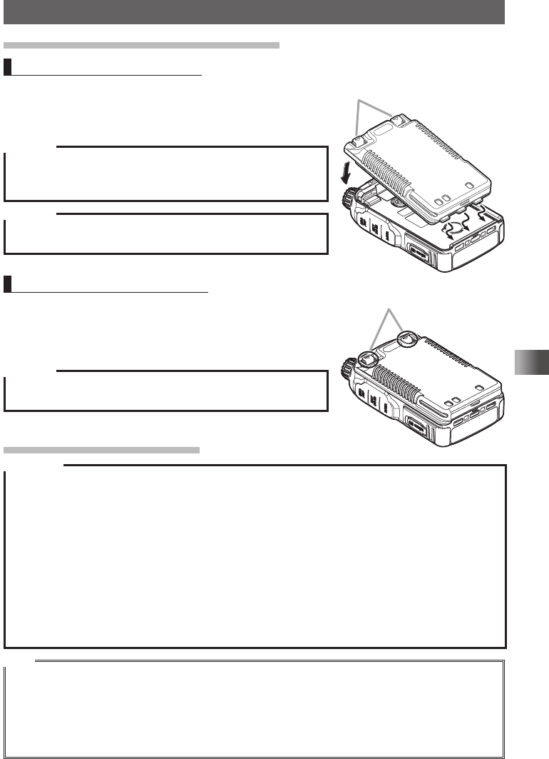
1 Insert the bottom tabs of the battery pack in the slots
at the bottom of the transceiver.
2 Push the battery in until the latches click securely.
Caution
When you use the transceiver for the first time after purchase
or you have not used it for a long period, charge the battery
pack before use.
Caution
Risk of explosion if battery is replaced by an incorrect type.
Dispose of used batteries according to the instructions..
Removing the Battery Pack
1 While pushing down and releasing the latches, re-
move the battery pack, as shown in the battery pack
removal illustration.
Caution
When releasing the battery latches, be careful not to hurt your
fingers and nails.
Charging the Battery Pack
Cautions
The battery pack is rechargeable about 300 times. However, improper use such as overcharge or
over-discharge can shorten its service life.
The battery pack is a consumable item. Recharging the battery pack repeatedly will gradually short-
en the duration of its usage.
If the transceiver is not used for a long period with the battery pack installed, deterioration of the
battery pack can accelerate.
If you do not use the transceiver for a long period, be sure to store it with the battery pack removed.
Even if you do not use the transceiver for a long period, install the battery pack biannually and re-
charge the battery pack about 50% to prevent it from over-discharging.
Storing the battery pack in a high-temperature place can deteriorate it faster than usual. Store the
battery pack in a place where the ambient temperature is –20 °C to +50 °C (–4 °F to +122 °F).
Do not drop or give a strong shock to the battery pack. It can break.
Tips
The battery pack contains lithium-ion batteries that can be recharged for repetitive use.
The transceiver can be used with either of the following battery packs:
(1) Accessory: SBR-14LI (7.2 V, 2,200 mAh)
(2) Option: FNB-101LI (7.4 V, 1,100 mAh)
When the battery pack is recharged, its output voltage (about 8 V) becomes higher than the speci-
fied value (7.4 V). This is not a failure.
Push down on the latches in the
direction of the arrow
.
Lock dials
Application for FCC / IC
FCC ID: K6620445X20
IC: 511B-20445X20
18
Basic Operation
Preparation
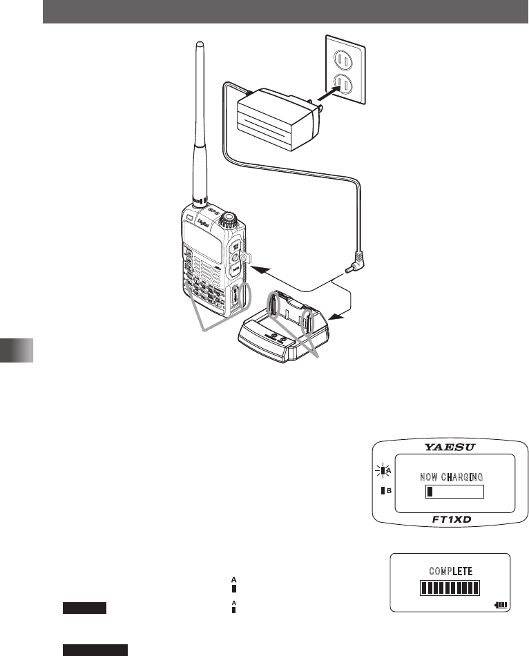
Battery charger
PA-48 or SAD-11B
(accessory)
Grooves in
battery pack
Rails
Rapid Charger CD-41
(option)
1 Install the Battery Pack
2 Turn off the transceiver.
3 Insert the plug of the battery charger (PA-48 or
SAD-11B) in the EXT DC IN jack of the transceiver.
Charging starts.
While the battery is being charged, the display will indi-
cate “NOW CHARGING”.
The charge level is indicated by a bar graph.
It takes about 8 hours to charge the battery pack fully.
When charging is completed, the display will change to
indicate “COMPLETE” and the lamp will glow green.
Remark In the USA Version, the lamp is not lit when charg-
ing or when charging is complete. When the charge is
complete, the transceiver turns off after 3 minutes.
Supplement • It takes about 5 hours to charge the FNB-101LI (option).
• The optional Rapid Charger (CD-41) requires about 4 hours to charge the supplied battery pack
(about 2.5 hours to charge the optional battery pack FNB-101LI).
Place the battery pack on the CD-41 so that the rails of the CD-41 fit into the grooves on the battery
pack.
When charging the battery pack using the CD-41, the LED on the CD-41 indicates the state of charging.
During charging: Lights red → Fast blink → Slow blink
Completion of charging: Lights green
䎱䎲䎺䎃䎦䎫䎤䎵䎪䎬䎱䎪
䎦䎲䎰䎳䎯䎨䎷䎨
Application for FCC / IC
FCC ID: K6620445X20
IC: 511B-20445X20
19
Basic Operation
Preparation
4 When charging is complete, remove the plug of the battery charger from the jack of
the transceiver.
Cautions
Neither transmission nor reception can be performed while charging the battery pack using the sup-
plied battery charger.
Charging may cause noise in the nearby TV or radio. Charge the battery pack with the battery char-
ger as far away as possible from a TV or radio.
If “BATTERY NOT INSTALLED” appears on the LCD and the battery pack cannot be charged after
lapse of 11 or more hours, stop charging the battery pack immediately. If the same message ap-
pears again, the battery pack is presumably at the end of its service life or defective. If so, replace
the battery pack with a new one.
While charging the battery pack, protect the transceiver from water.
Charge the battery pack in a place where the ambient temperature is +5 °C to +35 °C (+41 °F to
+95 °F).
If the terminal or electrode of the battery case is dirty, this transceiver can malfunction due to poor
contact, resulting in overheating or rupture. If the terminal or electrode gets dirty, clean it using a dry
cloth or cotton swab.
Tips
• The battery charger may become hot during charging. This is not a malfunction.
• If _ starts blinking, the battery pack charge is depleted. Charge it immediately.
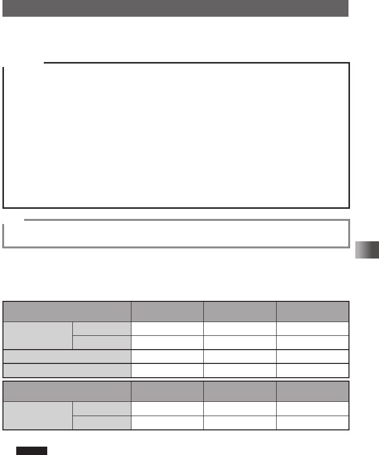
Approximate Operating Time and Remaining Charge Level Indication
Approximate time to operate the transceiver with the fully charged battery pack or three
new AA alkaline batteries is as follows:
Band in Use
Digital: OFF
Battery pack
FNB-101LI
Battery pack
SBR-14LI
Battery
FBA-39
Amateur Band
144 MHz band Approx. 5.0 hours Approx. 10.0 hours Approx. 15.5 hours
430 MHz band Approx. 4.5 hours Approx. 9.0 hours Approx. 15 hours
AM Broadcast Band Approx. 10.0 hours Approx. 20.0 hours Approx. 18.0 hours
FM Broadcast Band Approx. 8.0 hours Approx. 16.0 hours Approx. 14.5 hours
Band in Use
Digital: ON
Battery pack
FNB-101LI
Battery pack
SBR-14LI
Battery
FBA-39
Amateur Band
144 MHz band Approx. 4.0 hours Approx. 8.0 hours Approx. 11.0 hours
430 MHz band Approx. 3.6 hours Approx. 7.2 hours Approx. 10.5 hours
Transmission 6 seconds: Reception 6 seconds (VOL Level 16): Stand By 48 seconds (SAVE1:5)
Remark Approximate hours are estimated assuming that the transceiver is operated under the fol-
lowing conditions. The operation time that this transceiver can be actually used varies
depending on use conditions, ambient temperature, etc.
• When the GPS function is deactivated.
• When the transceiver is repeatedly operated by high-power transmission for 6 seconds
and reception for 6 seconds, and standby for 48 seconds with an amateur ham radio band
selected.
Application for FCC / IC
FCC ID: K6620445X20
IC: 511B-20445X20
20
Basic Operation
Preparation
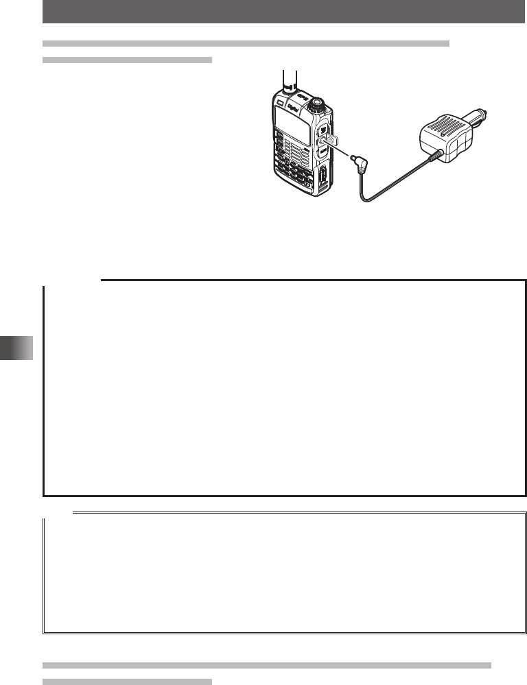
Connecting an External Power Supply for Use in Vehicle
(USA/EXP version only)
The optional external power supply
adapter with a cigarette lighter plug
(SDD-13) allows the transceiver to be
used in a vehicle.
1 Turn off the transceiver.
2 Insert the plug of the external power
supply adapter with a cigarette light-
er plug (SDD-13) in the EXT DC IN
jack of the transceiver.
3 Insert the cigarette lighter plug of the
external power supply adapter (SDD-13) in the cigarette lighter socket of the vehicle.
Cautions
The SDD-13 is compatible with a 12 VDC cigarette lighter socket. Do not connect the SDD-13 to the
24 VDC cigarette lighter socket.
Use the transceiver at the minimum required transmission power level to prevent overheating.
Do not continue transmission for a prolonged period of time. The transceiver may overheat, resulting
in malfunction or burns.
If you operate the transceiver for 7 hours or longer, it is recommended that you remove the battery
pack and install the optional battery case (FBA-39).
Recharging the fully-charged battery pack repeatedly can shorten its service life. Be extremely
careful not to do so when you operate the transceiver when using an external power supply.
While charging the battery pack, protect the transceiver from water.
Charge the battery pack in a place where the ambient temperature is +5 °C to +35 °C (+41 °F to
+95 °F).
If the terminal or electrode of the battery case is dirty, the transceiver can malfunction due to poor
contact, resulting in overheating or rupture. If the terminal or electrode gets dirty, clean it using a dry
cloth or cotton swab.
Tips
• The battery pack can be charged within approximately 8 hours using the external power supply (ap-
proximately 5 hours to charge the optional battery pack FNB-101LI). If the battery pack is charged with
the transceiver turned on, the charging time increases slightly.
• When the battery pack has been fully charged, charging stops automatically.
• The external power supply can be used with the battery case installed.
• If you connect the transceiver to the external power supply with it turned off, “CONNECTED TO EX-
TERNAL POWER” appears on the LCD, and about 20 seconds later “BATTERY NOT INSTALLED”
appears.
Connecting to an External Power Supply Using a Power Cable
(USA/EXP version only)
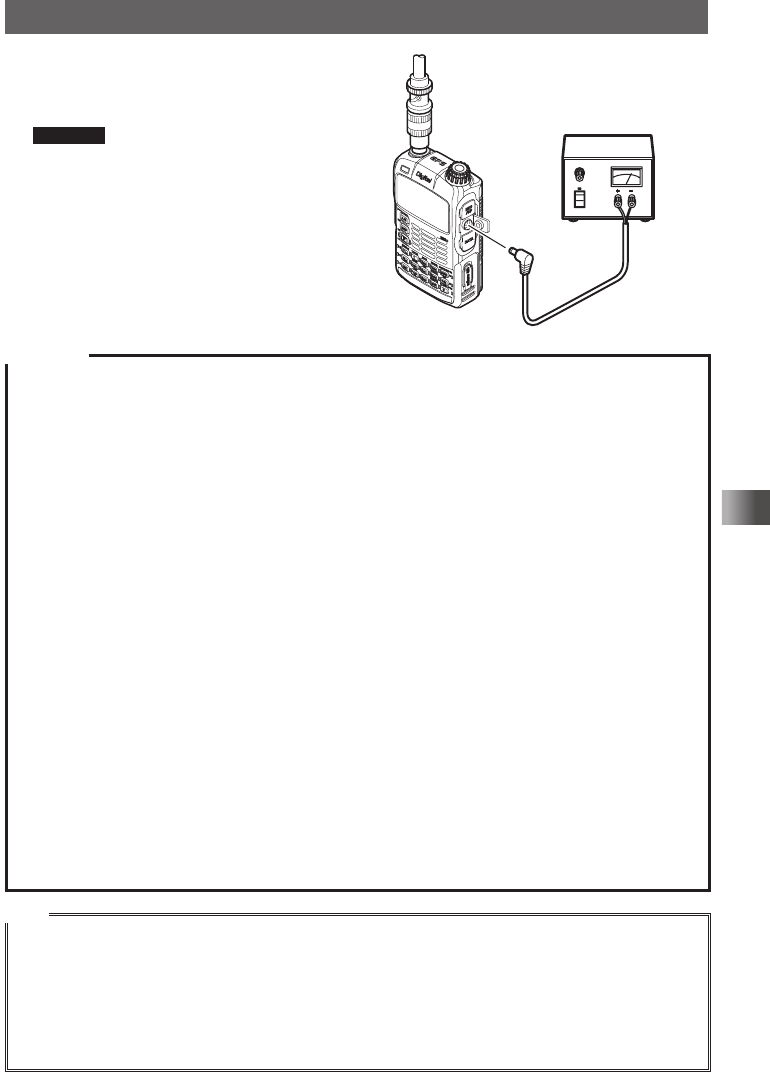
The optional power cable (E-DC-6) allows the transceiver to be connected to an external
power supply.
To cigarette lighter socket
of vehicle
EXT DC IN jack
External power supply
adapter with a cigarette
lighter plug
SDD-13 (option)
Application for FCC / IC
FCC ID: K6620445X20
IC: 511B-20445X20
21
Basic Operation
Preparation
1 Turn off the transceiver.
2 Connect the optional external power supply
cable (E-DC-6) to an external power supply.
Remarks • Connect the red/black wire or white/red
wire to the positive (+) terminal of the
external power supply and the black
wire to the negative (–) terminal.
• Set the voltage of the external power
supply to 12 to 14 V.
3 Insert the plug of the external power supply
in the EXT DC IN jack of the transceiver.
Cautions
When you use the transceiver with the external power supply cable (E-DC-6) connected to an exter-
nal power supply, pay attention to the following:
The power supply voltage must be between 12 V and 14 V.
If the voltage exceeds 14 V, the high voltage protection function is activated to disable high-power
transmission. L3 (2.5 W) is selected automatically to reduce the transmission power. If the voltage
exceeds 16 V, malfunctions such as damage to the electric circuits of the transceiver may result.
Take extra care.
Connect the red/black wire or white/black wire of the external power supply cable (E-DC-6) to the
positive (+) terminal of the external power supply and the black wire to the negative (–) terminal.
Use an external power supply having sufficient current capacity (3 A or more).
If the transceiver is used with supplied antenna connected, the external power supply can malfunc-
tion, resulting in a failure. If you use an external power supply, remove the supplied antenna and
connect an external antenna. Place the external power supply sufficiently away from the transceiver.
Use the transceiver at the minimum required transmission power level to prevent overheating.
Do not continue transmission for a prolonged period. The transceiver may overheat, resulting in
malfunction or burn.
If you operate the transceiver for 7 hours or longer, it is recommended that you remove the battery
pack and install the optional battery case (FBA-39).
Recharging the fully-charged battery pack repeatedly can shorten its service life. Be extremely care-
ful not to do so when you operate the transceiver using an external power supply.
While charging the battery pack, protect the transceiver from water.
Charge the battery pack in a place where the ambient temperature is +5 °C to +35 °C (+41 °F to
+95 °F).
If the terminal or electrode of the battery case is dirty, the transceiver may malfunction due to poor
contact, resulting in overheating or rupture. If the terminal or electrode gets dirty, clean it using a dry
cloth or cotton swab.
Tips
• The transceiver can be charged within approximately 8 hours using the external power
supply(approximately 5 hours to charge the optional battery pack FNB-101LI). If the battery pack is
charged with the transceiver turned on, the charging time increases slightly.
• The external power supply can be used with the battery case installed.
If you connect the transceiver to the external power supply with it turned off, “CONNECTED TO EX-
TERNAL POWER” appears on the LCD, and about 20 seconds later “BATTERY NOT INSTALLED”
appears.
Connect the external
antenna. External power supply
External power supply
cable E-DC-6 (option)
Application for FCC / IC
FCC ID: K6620445X20
IC: 511B-20445X20

22
Basic Operation
Using a microSD memory card
Using a microSD memory card with the transceiver allows the following functions.
You can:
Back up information on the transceiver.
Save memory information.
Save data other than images.
Save GPS log data.
Save image data captured with the optional camera-equipped microphone (MH-
85A11U).
Save messages downloaded with the GM function or WIRES-X function.
Usable microSD memory cards
This transceiver only supports the following capacity of microSD and microSDHD mem-
ory cards.
• 2GB • 4GB • 8GB • 16GB • 32GB
Cautions when using a micro SD memory card
Do not bend or place heavy objects on the microSD memory card.
microSD memory cards formatted on other devices may not properly save information
when used with this transceiver. Format micro SD memory cards again with this trans-
ceiver when using memory cards formatted with another device.
When saving data to a microSD memory card, do not remove the microSD memory
card or turn off the transceiver.
Do not insert anything other than microSD memory card into the microSD memory card
slot of the transceiver.
Do not attempt to forcefully remove mounted microSD memory card.
Do not use microSD memory cards other than those specified by Yaesu. For the infor-
mation on the specified products, please contact Yaesu Amateur Ham Radio Customer
Support.
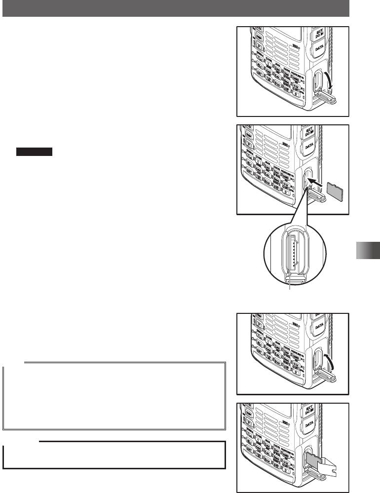
Mounting and dismounting microSD memory card
1 Turn off the transceiver.
Application for FCC / IC
FCC ID: K6620445X20
IC: 511B-20445X20
23
Basic Operation
Using a microSD memory card
2 Open the microSD cover on the side of the transceiver.
3 Insert the microSD memory card into the card slot until
you hear a click. (as shown in the figure at the right).
Cautions • Ensure that the microSD memory card is facing the
proper direction when mounting it.
• Do not touch the terminal of the microSD memory
card.
Do not push the microSD
memory card into this space.
4 Close the microSD cover.
When the microSD memory card is properly detected,
the s lights on the display.
Tips
Dismounting the microSD memory card.
To dismount the microSD memory card, as done in step 3 above,
push the memory card in until you hear a click, then remove the
memory card.
* By using the micro SD Card Clip, it is easy to remove the micro
SD memory Card.
Caution
Do not turn off the transceiver while the data is being written to
the microSD memory card. Doing so may corrupt the data.
Application for FCC / IC
FCC ID: K6620445X20
IC: 511B-20445X20
24
Basic Operation
Using a microSD memory card
Formatting a microSD memory card
Format a new microSD memory card following the steps below before use.
Caution
Formatting a microSD memory card erases all data saved to it. If you are going to format the microSD
memory card you are using, be sure to check the data saved to it before formatting.
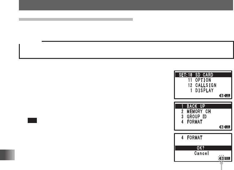
1 Press and hold M over 1 second.
2 Turn O to select [10 SD CARD].
3 Press H.
4 Turn O to select [4 FORMAT].
5 Press H.
[OK?] appears on the LCD.
Tip To cancel formatting, select [Cancel].
6 Press H.
S (sicon) on the LCD blinks and formatting starts.
When formatting is completed, a beep sound is emitted and
[Completed] appears on the LCD.
Blinking while formatting is
in progress
Application for FCC / IC
FCC ID: K6620445X20
IC: 511B-20445X20
25
Basic Operation
Performing Communication
Try communication using the transceiver in the analog communication mode.
Follow the procedure below:
Turn on the transceiver
Adjust the Volume Level
Select an Operating Band
Select a Frequency Band
Turn in to a Frequency
Perform Communication
Turning on the Transceiver
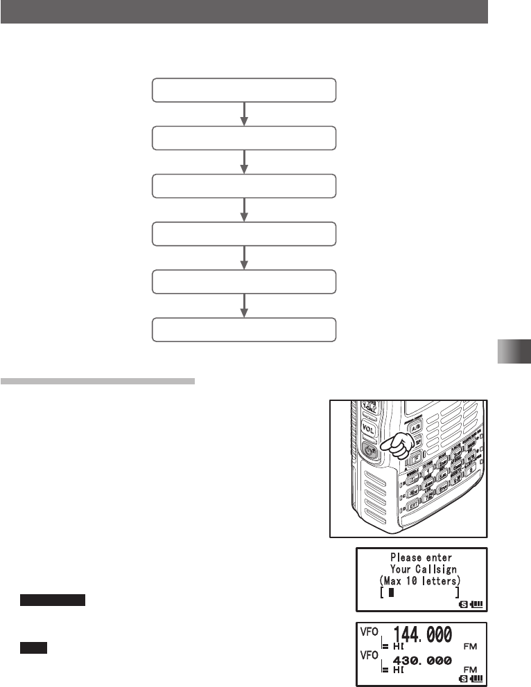
1 Press and hold P over 1 second.
2 The callsign input screen appears.
The callsign input screen appears when the transceiver
is turned on for the first time after purchase.
The next time, the frequency screen will appear after
the opening screen.
3 Input a callsign for your transceiver.
Input the callsign with the ten key.
4 Press p.
The callsign is set and two frequencies (A-band and
B-band frequency) appear at the same time.
Supplement Factory settings are:
A-band (upper): 144.000 MHz
B-band (lower): 430.000 MHz
Tips You can change the information such as the power supply
voltage and the opening message displayed at power-on.
For example, press and hold M over 1 second to enter
the Set mode and then select [1 DISPLAY] → [9 OPENING
MESSAGE] to change the opening message.
In addition, you can set the transceiver to display the reception frequency immediately without
displaying the opening message (See page 107).
Application for FCC / IC
FCC ID: K6620445X20
IC: 511B-20445X20