Yaesu Musen 20445X20 AMATEUR RADIO WITH SCANNING RECEIVER User Manual cover pmd
Yaesu Musen Co., Ltd. AMATEUR RADIO WITH SCANNING RECEIVER cover pmd
Contents
USERS MANUAL

C4FM FDMA 144/430 MHz
DUAL BAND DIGITAL TRANSCEIVER
OPERATING MANUAL
YAESU MUSEN CO., LTD.
Tennozu Parkside Building
2-5-8 Higashi-Shinagawa, Shinagawa-ku, Tokyo 140-0002 Japan
YAESU USA
6125 Phyllis Drive, Cypress, CA 90630, U.S.A.
YAESU UK LTD.
Unit 12, Sun Valley Business Park, Winnall Close
Winchester, Hampshire, SO23 0LB, U.K.
YAESU HK LTD.
Unit 1306-1308, 13F., Millennium City 2, 378 Kwun Tong Road,
Kwun Tong, Kowloon, Hong Kong
FT1DR
FCC ID: K6620445X20
IC: 511B-20445X20
YAESU MUSEN CO., LTD.

2
Before Reading This Manual
Before Reading This Manual
Contents
Recalling a Memory Channel ............................... 41
Recalling the Home Channel ............................... 42
Returning to the Previous Frequency .............. 42
Deleting the Memory Channel ............................. 42
Restoring the Deleted Memory Channel ......... 43
Using Memory Banks ............................................... 43
Registering a Memory Channel in a Memory
Bank ..................................................................... 44
Recalling a Memory Bank .................................... 44
Canceling Memory Channel Registration in a
Memory Bank ...................................................... 45
Convenient Special Banks ....................................... 45
Registering Your Favorite Special Memory
Channels in a Memory Bank ................................ 45
Recalling a Special Bank to Listen to the JR
Railway Radio ...................................................... 46
Recalling a Special Bank to Listen to the
International VHF (Marine) Radio ........................ 46
Scanning Function ................................................. 48
Using the Scanning Function.................................... 48
VFO Scan ............................................................ 48
Canceling Scanning ........................................ 49
Skipping a Frequency You Do Not Want Scan
(Skip Search Memory) .................................... 49
Specifying the Frequency You Do Not Want to
Scan ................................................................ 50
Deleting a Frequency Saved in the Skip Search
Memory ........................................................... 50
Selecting a Reception Method When Scanning
Stops ............................................................... 51
Memory Scanning ................................................ 51
Specifying a Skip/Selected Memory Channel
........................................................................ 53
Scanning Only the Selected Memory
Channel ........................................................... 54
Scanning a Memory Bank .................................... 54
Memory Bank Link Scan ................................. 55
Programmable Memory Scan (PMS) ................... 56
Writing into a Programmable Memory ............. 56
Performing Programmable Memory Scan ....... 56
Using the Search Function ....................................... 57
Spectrum Scope Searching for a Signal
Using a Signal Strength Graph ....................... 57
Using the GPS Function ........................................ 58
What is GPS? ........................................................... 58
Activating the GPS Function..................................... 58
Method of Positioning by GPS.................................. 59
Explanation of GPS Screen and Operation .............. 61
BACK TRACK Function ............................................ 62
Causing the FT1DR to Memorize the Current
Point ..................................................................... 62
Using the BACK TRACK Function ....................... 63
Description of the BACK TRACK Function Screen
............................................................................. 63
Before Reading This Manual ................................... 2
Introduction ................................................................. 4
Features of FT1DR ................................................ 4
How to Read This Manual ...................................... 5
Checking Bundled Items ........................................ 5
Safety Precautions (Be Sure to Read) ....................... 6
Names and Functions of Controls ............................ 12
Basic Operation ...................................................... 15
Preparation ............................................................... 15
Installing the Antenna........................................... 15
Attaching the Supplied Belt Clip/Protective Cap
............................................................................. 15
Attaching the Protective Cap ........................... 15
Installing the Belt Clip ...................................... 15
Attaching a Hand Strap ........................................ 16
How to Use the Battery Case (FBA-39) (Option)
............................................................................. 16
Installing/Removing the Battery Pack .................. 17
Installing the Battery Pack ............................... 17
Removing the Battery Pack ............................. 17
Charging the Battery Pack ................................... 18
Connecting an External Power Supply for Use in
Vehicle ................................................................. 20
Connecting to an External Power Supply Using a
Power Cable ........................................................ 21
Communication......................................................... 23
Turning on the Power ........................................... 23
Adjusting the Volume Level.................................. 24
Selecting an Operating Band ............................... 25
Selecting a Frequency Band ................................ 27
Tuning in to a Frequency ..................................... 28
Performing Communication ................................. 29
Listening to the Radio ............................................... 30
Listening to an AM or FM Broadcast .................... 30
To deactivate the radio function ...................... 31
To scan through the radio band ....................... 31
Switching between AM Antennas ......................... 31
Miscellaneous Settings ............................................. 32
Setting the Date and Time ................................... 32
Setting the Time Signal ........................................ 33
Muting Audio ........................................................ 33
Changing the Transmission Power Level............. 34
Adjusting the Squelch Level................................. 35
Changing the Frequency Step Manually .............. 35
Changing the Mode Manually .............................. 36
Locking keys or switches ..................................... 37
Restoring to Defaults (All Reset).......................... 37
Repeater Operation ................................................ 38
Repeater Operation .................................................. 38
Communicating Via the Repeater ........................ 38
Using the Memory .................................................. 39
A Wide Variety of Memory Functions ........................ 39
Writing into the Memory ....................................... 40
Split Memory ........................................................ 41
FCC ID: K6620445X20
IC: 511B-20445X20
YAESU MUSEN CO., LTD.

3
Before Reading This Manual
Contents
Useful Functions .................................................... 64
Dual Reception (DW) Functions ............................... 64
Dial Dual Reception
VFO mode Priority memory channel ........................ 64
Memory Dual Reception
Memory channel Priority memory channel ................ 65
Home Channel Dual Reception
Home channel Priority memory channel .................. 65
Using the DTMF Function......................................... 66
Confirming the Entered DTMF Code by the
Sound .............................................................. 67
Sending the Registered DTMF Code ................... 67
Sending a DTMF Code Manually ......................... 68
Communicating with a Specific Remote Station
.................................................................................. 69
Using the Tone Squelch Function ............................. 69
Selecting a Tone Frequency ............................ 70
Selecting a DCS Code .................................... 71
Searching for the Frequency of the DCS Used
by the Remote Station ..................................... 72
Notification of Call from the Remote Station by
Vibration of the Vibrator ....................................... 73
Selecting a Vibrator Operation Mode .............. 73
Notification of Call from a Remote Station by the
Bell Bell Function ................................................. 74
Changing the Number of Times the Bell
Rings ............................................................... 75
Calling Only a Specific Station New Pager
Function ............................................................... 75
Flow of Operation to Use the Pager Function
........................................................................ 76
Setting the Code of Your Station ..................... 76
Turning on the New Pager Function ................ 77
Calling a Specific Station ................................ 77
Being Called by the Remote Station
(Standby Operation) ........................................ 78
Functions Used As Needed ................................... 79
Set Mode .................................................................. 79
Selecting Set Mode Items .................................... 79
Resetting the Set Mode Items ......................... 79
Set Mode Item List .............................................. 80
FT1DR Specifications............................................. 87
FCC ID: K6620445X20
IC: 511B-20445X20
YAESU MUSEN CO., LTD.

4
Before Reading This Manual
Introduction
Features of FT1DR
Digital communication (C4FM (Quaternary FSK), FDMA system) ........................... 000
External power supply terminal ................................................................................ 000
Reception on two different bands + Reception on two identical bands (V+V/U+U) . 000
Independent switching keys for A-band and B-band and TX/BUSY display ............ 000
Wide-band reception over the range of 500 kHz to 999.900 MHz ........................... 000
Waterproofing design 20 conforming to IPX5, which protects the FT1DR from
rain and splashes ..................................................................................................... 000
Independent side keys, a full keyboard for easy entry of data,
and a tilted main dial. .............................................................................................. 000
Easy-to-see dot matrix display ................................................................................. 000
Ready for WiRES-II and WiRES-X connection (realized by the incorporated
64-channel WiRES-II access memory) .............................................Refer to CD-ROM.
Large-capacity 1327 ch memory and twenty-four 100 ch memory banks ............... 000
Display of a memory tag comprising up to 16 one-byte characters ......................... 000
Special banks for easy reception ............................................................................. 000
Just by selecting preset frequencies, you can receive AM/FM, shortwave broadcast,
international VHF radios with ease. ........................................................................ 000
A wide variety of scan functions ............................................................................... 000
Built-in GPS unit allowing display of your current location and
heading information ................................................................................................. 000
Ready for APRS® communication through use of world standard
1200/ 9600bps AX25 modem (B-band only) ........................................... See CD-ROM.
High-resolution spectrum scope function for ±50 channels .................................... 000
A variety of individual calling functions such as tone squelch (CTCSS) and DCS
functions .................................................................................................................. 000
Vibrator for informing you of signal reception in addition to the bell ....................... 000
New pager function for calling only specific stations ................................................ 000
Illumination by white LED for easy viewing of the LCD outdoors ............................ 000
Built-in temperature sensor ...................................................................................... 000
Battery save function for prolonging the operating time of the battery ..................... 000
Data terminal for data communication with external equipment or
firmware update ....................................................................................................... 000
Build-in bar antenna for AM reception ..................................................................... 000
Ready for micro SD ................................................................................................. 000
Snapshot function (an optional camera microphone MH-85A11U is required)
................................................................................................................ See CD-ROM.
FCC ID: K6620445X20
IC: 511B-20445X20
YAESU MUSEN CO., LTD.
5
Before Reading This Manual
Introduction
How to Read This Manual
Typical explanatory expressions used in this manual are as follows:
Press the B key briefly.
Press and hold the B key for over 1 second.
FB... (Press the F key, and then press the B key.)
While pressing the v key, turn the O knob.
Precaution
...Explains notes to follow during operation.
Hint
...Explains operating suggestions or useful hints.
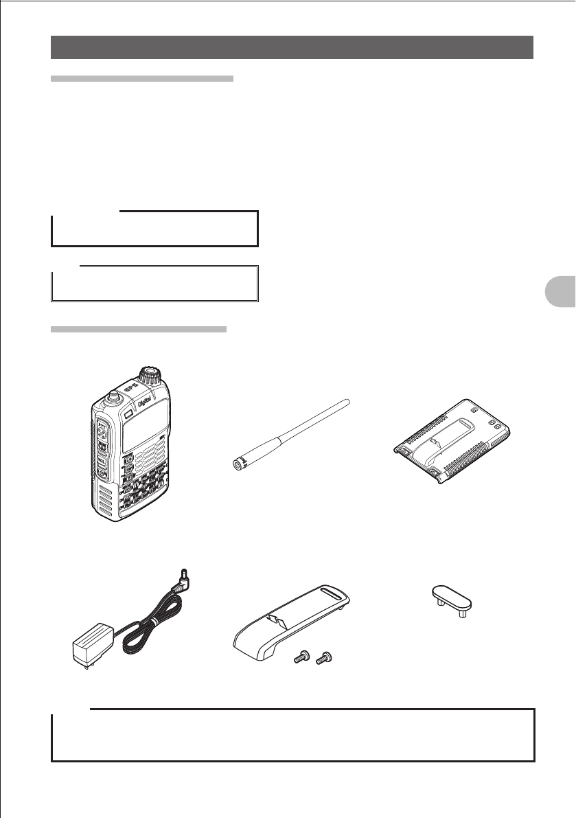
Checking Bundled Items
Main unit Antenna Battery pack (FNB-101LI)
Battery charger (PA-48) Belt clip Protective plate for battery
pack
• Operating Instruction
(this manual)
• Warranty
Notes
zMake sure that the name of the shop from which you purchased the product and the date of
purchase are indicated on the warranty card.
zIf any item is missing, contact the shop from which you purchased the product.
FCC ID: K6620445X20
IC: 511B-20445X20
YAESU MUSEN CO., LTD.
6
Before Reading This Manual
Safety Precautions (Be Sure to Read)
Safety Precautions (Be Sure to Read)
Be sure to read the safety precautions to use this product safely.
We are not liable for failures and other problems caused due to misuse or use of this
product by you or a third party as well as the damages caused through use of this
product by you or a third party except in the case where we are ordered to pay for
damages under the laws.
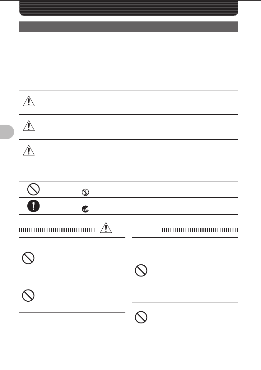
Types and Meanings of Symbols
DANGER Indicates an imminently hazardous situation which, if not
avoided, could result in death or serious injury.
WARNING Indicates a potentially hazardous situation which, if not
avoided, could result in death or serious injury.
CAUTION
Indicates a potentially hazardous situation which, if not
avoided, may result in minor or moderate injury or only
property damage.
Types and Meanings of Legends
Indicates a prohibited item not to be done in order to use this product safely.
For example, indicates that the product should not be disassembled.
Indicates an obliged item to be done in order to use this product safely.
For example, indicates that the power plug should be removed.
DANGER
Do not use this product in “an area
where use of it is prohibited”, e.g.,
inside the hospital, airplane, or
train.”
This product can affect electronic or
medical devices.
Do not use this product while riding
a bicycle or driving a car. Accidents
can result.
Be sure to stop the bicycle or car at a
safe place before using this product.
Those who are carrying a medical
device such as a cardiac pacemaker
should not perform transmission
near it. When performing
transmission, use an external
antenna and keep away from the
external antenna as far as possible.
The radio wave emitted from this
product can cause the medical device
to malfunction and result in an accident.
Do not use this product or the
battery charger in a place where
inflammable gas is generated.
A fire or explosion can occur.
FCC ID: K6620445X20
IC: 511B-20445X20
YAESU MUSEN CO., LTD.
7
Before Reading This Manual
Safety Precautions (Be Sure to Read)
Do not perform transmission in a
crowded place for the safety of the
persons carrying a medical device
such as a cardiac pacemaker.
The radio wave emitted from this
product can cause the medical device
to malfunction and result in an accident.
Do not touch the liquid leaking from
the battery pack with bare hands.
The liquid that has stuck to your skin or
entered in your eye can cause chemical
burn. In such a case, consult the doctor
immediately.
Do not solder or short-circuit the
terminal of the battery pack.
A fire, leak, overheating, explosion, or
ignition can result.
Do not carry the battery pack together
with a necklace or hair pin. A short
circuit can result.
If it starts thundering when
the external antenna is used,
immediately turn off this product
and disconnect the external antenna
from it.
A fire, electrical shock, failure can
result.
WANING
Do not use this product at a voltage
other than the specified power
supply voltage.
A fire or electric shock can result.
Do not use the battery pack for any
model other than the specified mode.
A fire, leak, overheating, explosion, or
ignition can result.
This product has a waterproof
structure and conforms to “IPX5”
when the included antenna and
battery pack are installed and rubber
caps are securely attached to the
MIC/SP jack, EXTDC IN jack, DATA
terminal, and micro SD slot. If this
product gets wet, wipe it with a dry
cloth, etc. without leaving it as it is.
Leaving this product in a wet condition
can degrade its performance, shorten
its life, or cause a failure or electrical
shock.
Do not perform transmission for a
long period.
The main body can overheat, resulting
in a failure or burn.
Do not disassemble or make any
alteration to this product.
An injury, electric shock, or failure can
result.
Do not handle the battery pack or
charger with wet hands. Do not
insert or remove the power plug with
wet hands.
An injury, leak, fire, or failure can result.
If smoke or strange odor is emitted
from the main body, battery pack,
or battery charger, immediately turn
off this product, remove the battery
pack, and remove the power plug
from the outlet.
A fire, leak, overheating, damage,
ignition, or failure can result. Contact
the shop from which you purchased
this product or our Amateur Customer
Support.
Do not use the battery pack which is
externally damaged or deformed.
A fire, leak, hating, explosion, or ignition
can result.
Do not use any battery charger
which is not specified by us.
A fire or failure can result.
Keep the terminals of the battery
pack clean.
If stained, a fire, leak, overheating,
explosion, or ignition can result.
FCC ID: K6620445X20
IC: 511B-20445X20
YAESU MUSEN CO., LTD.
8
Before Reading This Manual
Safety Precautions (Be Sure to Read)
If charging of the battery pack
cannot be completed after lapse
of the specified time, immediately
remove the power plug of the battery
charger from the outlet.
A fire, leak, overheating, explosion, or
ignition can result.
CAUTION
Do not dangle or throw this product
by holding its antenna.
This product can hit and injure
someone. In addition, doing so can
result in a main body failure or damage.
Do not use this product in a crowded
place.
The antenna can hit someone, resulting
in a injury.
Do not place this product in a place
subject to direct sunlight or near a
heater.
This product can deform or discolor.
Do not place this product in a humid
or dusty place.
A fire or failure can result.
During transmission, keep the
antenna away from you as far as
possible.
Long-time exposure to electromagnetic
waves can have a negative impact on
your health.
Do not clean the case with thinner or
benzene.
Use a soft, dry cloth to clean the case.
If you do not use this product for a
long period, turn it off and remove
the battery pack for safety.
Do not give a strong shock to or
throw this product.
A failure can result.
Keep magnetic cards and video tape
away from this product.
The data recorded on cash cards or
video tape can be erased.
Do not use the earpiece microphone,
earphones, or headphones at an
extremely high volume level.
Hearing impairment can result.
Keep this product out of reach of
children.
An injury, etc. can result.
Install the hand strap and belt click
securely.
If they are installed improperly, they
can fall down, resulting in an injury or
damage.
Do not place a heavy thing on the
power cord of the battery charger.
The battery cord can be damaged,
resulting in a fire or electric shock.
Do not use the included battery
charger to charge any battery pack
which is not specified by us.
A fire can result.
Do not perform transmission near
the TV or radio.
Radio disturbance can occur in this
product, TV, or radio.
Do not use any products other than
the options specified by us.
A failure can result.
When the battery charger is not in
use, remove its power plug from the
outlet
FCC ID: K6620445X20
IC: 511B-20445X20
YAESU MUSEN CO., LTD.

9
Before Reading This Manual
Safety Precautions (Be Sure to Read)
Charge the battery pack within the
temperature range from 5°C to 35°C.
Charging the battery pack outside this
temperature range can cause leak,
overheating, decrease in performance,
or reduction in service life can result.
When unplugging the power cord of
the battery charger, be sure to hold
the power plug.
Pulling the power cord can damage it
and cause a fire or electronic shock.
Before discarding the worn battery
pack, affix tape or the like to its
terminals.
When using this product in a hybrid
or fuel-saving car, be sure to check
with the automobile manufacturer if
the it can be used in that car.
Noise generated by an onboard
electrical device (inverter, etc.) can
disable normal reception by this
product.
FCC ID: K6620445X20
IC: 511B-20445X20
YAESU MUSEN CO., LTD.

10
Before Reading This Manual
Safety Precautions (Be Sure to Read)
About Waterproo ng Feature Conforming to IPX5
When the included antenna and battery pack are installed and the MIC/SP jack, EXT
DC IN jack, DATA terminal, and micro SD slot are securely covered with rubber caps,
this product can withstand continuous 30-minute immersion in water at depth of 1
m. To ensure this waterproofing feature, be sure to check the following points before
use.
Check for damages, deterioration, and dirt.
Antenna rubber, key switch rubber, MIC/SP jack, EXT DC IN jack, DATA terminal, micro SD
slot rubber cap, and battery pack joint.
Cleaning
When this product is contaminated with seawater, sand, or dirt, rinse with fresh water, and
then wipe with a dry cloth immediately.
Recommended maintenance interval
It is recommended that you ask for maintenance of this product when one year has passed
since purchase or previous maintenance or when any damage or deterioration is found. Note
that the maintenance service is subject to fees.
Do not immerse this product in the following liquids:
Sea, pool, hot spring, water containing soap, detergent, or bath additive, alcohol, or
chemicals
Do not leave this product for a long time in the following places:
Bathroom, kitchen, or humid place
Other precautions
Since this product is not totally waterproof, it cannot be used in water.
FCC ID: K6620445X20
IC: 511B-20445X20
YAESU MUSEN CO., LTD.

11
Before Reading This Manual
Before Transmitting Radio Waves
If you are informed that the radio waves emitted from your amateur station are
interfering with reception by the TV, radio, etc., of a neighbor, you should stop emitting
the radio waves and check whether any problem of interference and its degree if it
exists.
FCC ID: K6620445X20
IC: 511B-20445X20
YAESU MUSEN CO., LTD.
12
Before Reading This Manual
Names and Operation of Controls
Names and Functions of Controls
a
b
c
d
e
f
g
h
i
j
k
l
m
n
o
p
q
r
s
t
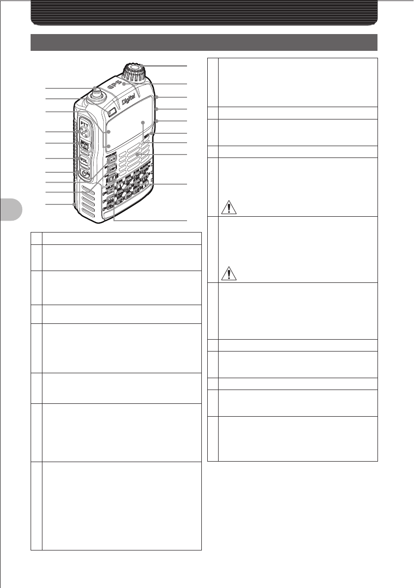
aAntenna terminal (SMA)*
bFlashlight (White LED)
• This LED can be used as a small flashlight in a
dark place.
cA-band BUSY/TX lamp
B-band BUSY/TX lamp
These lamps glow green during reception, and
glow red during transmission.
dpPTT switch
• Press and hold the p switch during transmission.
eTswitch
• Press and hold the T switch to deactivate the
squelch function.
• While pressing the F key and T switch, turn
the O knob to adjust the squelch level.
fv switch
While pressing the v key, turn the O knob to
adjust the volume level.
gP switch
• Press and hold the P switch over 1 second to
turn on the FT-D1.
• Press and hold the P switch over 1 second
again to turn off the FT-D1.
• Press the
P switch briefly to lock keys.
hAkey (switching between operating bands)
• Pressing the
A key briefly toggles between
A-band and B-band.
• Press and hold the A key over 1 second to
change the Dual Band Reception mode to the
Mono Band Reception mode.
• While operating the FT-D1 in the Mono Band
Reception mode, press the F key and then
press the A key briefly to enlarge the
display.
iM key
• Pressing the
M key switches among display
modes (frequency APRS and GPS).
• Press the hold the M key over 1 second to call
the Set mode.
jBattery pack*
kO knob
Turn this knob to change frequencies or select a
memory channel.
lGPS antenna
mMIC/SP jack*
Connect a speaker microphone or earpiece
microphone to this jack.
It is not waterproofed when an external
microphone is connected.
Do not connect any product which is not
specified by us. A failure can result.
nEXT DC IN jack*
• Connect an external power supply adapter with
a cigarette lighter plug (E-DC-5B) or an external
power cable (E-DC-6) to this jack.
• When charging the battery pack, connect the
battery charger (PA-48) to this jack.
Do not connect any product which is not
specified by us. A failure can result.
oDATA terminal*
• Use this terminal when using a clone function or
updating the firmware.
• Connect the optional camera-equipped
microphone (MH-85A11U).
• For how to update the firmware, access our
home page.
pMicrophone
qDisplay
This LCD displays reception frequencies and
various settings.
rSpeaker
s15 keys
These keys are used to specify reception/
transmission frequencies and select functions.
tF switch
• Press the
F key briefly to activate function
keys.
• Press and hold the F key over 1 second to
write a frequency in the memory.
* When the included antenna and battery pack are
installed and the MIC/SP jack, EXT DC IN jack,
DATA terminal, and micro SD slot are securely
covered with rubber caps, the FT-D1 can deliver
the waterproofing performance conforming to
IPX5 (See page 10).
FCC ID: K6620445X20
IC: 511B-20445X20
YAESU MUSEN CO., LTD.

13
Before Reading This Manual
Names and Functions of Controls
Key
When pressed briefly
When pressed and held
over 1 second
When a key is
pressed after
the F switch is
pressed
When entering a
frequency or calling a
memory CH
When inputting a tag
%Switches between
radio wave types.
Moves the cursor to
the left.
Selects SD card data. Sends the selected
SD card data.
XTurns on/off the
WiRES-X function. ———
DTurns on/off the
GSM function. —Manipulates member
data. —
1Number “1” Number “1”
—
Switches between
transmission power
levels.
2Number “2” Number “2” or letter
“A”, “B”, “C”, “a”, “b”,
or “c”
—
Selects the spectrum
cope function.
3Number “3” Number “3” or letter
“D”, “E”, or “F”, “d”,
“e”, or “f”
—
Selects the special
bank function.
4Number “4” Number “4” or letter
“G”, “H”, or “I” , “g”,
“h”, or “i”
—
Selects the home
channel.
5Number “5” Number “5” or letter
“J”, “K”, or “L”, “j”, “k”,
or “l”
—
Selects a reversal
function.
6Number “6” Number “6” or letter
“M”, “N”, or “O”, “m”,
“n”, or “o”
—
Selects the AF DUAL
function.
7Number “7” Number “7” or letter
“P”, “Q”, “R”, or “S”,
“p”, “q”, “r”, or “s”
—
Displays a station
list.
8Number “8” Number “8” or letter
“T”, “U”, or “V”, “t”,
“u”, or “v”
—
Displays a digital list.
9Number “9” Number “9” or letter
“W”, “X”, “Y”, or “Z”,
“w”, “x”, “y”, or “z”
—
Selects a beacon
text.
0Number “0” Number “0” —Receives the AM/FM
radio band.
BIncreases the
frequency.
Moves the cursor to
the right.
Selects the scan
function.
Decreases the
frequency.
VSwitches between
the VFO mode and
Memory mode.
Switches between
letter types. —
Selects the dual
watch function.
FCC ID: K6620445X20
IC: 511B-20445X20
YAESU MUSEN CO., LTD.
14
Before Reading This Manual
Names and Functions of Controls
䰢䰒䰛
䰚䰒䰙
䰚䰒䰙
䰔䰕
䰔 䰕
䰔䰕
䰔 䰕
䯴䰀䯵
䰢䰒䰛 䰀䯿䯿䯺䯼䯼䯼
䯽䰀䰁䯺䯼䯼䯼
䯴䰃䯵
䰀
䯴䰃䯵
a
abc de f
bcd e f g
h
i
g
h
i
A-band
display area
B-band
display area
Icon
display
area
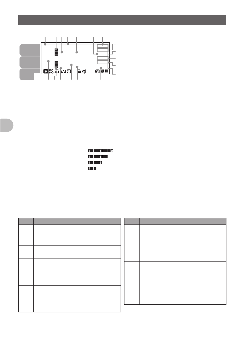
a
Displays choice of the VFO mode or MR
(memory) mode.
bDisplays a sound volume bar graph.
cDisplays a transmission power level icon.
dDisplays an operating frequency.
eS meter: Displays the radio wave strength in
9 steps.
PO meter: Displays the transmission power
level in 4 steps.
H I: High power (5 W)
L 3: LOW 3 power (2.5 W)
L 2: LOW 2 power (1 W)
L 1: LOW 1 power (0.05 W)
fDisplays the operating mode (radio wave
type).
gDisplays a squelch type (See page 136).
TN: Stays lit when the tone encoder
function is active.
TSQ: Stays lit when the tone squelch
function is active.
DCS: Stays lit when the DCS function is
active.
RTN: Stays lit when the reverse tone
function is active.
PAG: Stays lit when the pager is active.
MSG: Stays on when the message function
is active.
Displays the APRS baud rate (See page 71).
hDisplays a shift direction during repeater
operation. (See page 30)
-Minus shift
+Plus shift
@Split operation
b is displayed when the bell alarm function
is active (See page 140).
iDisplayed when the vibrator function is
active.
Solid line ():
BUSY vibrator function (See page 139)
Dashed line:
SIGNALING vibrator function (See page
139)
Short dashed line (----):
APRS MSG vibrator function (See page 96)
Icons
Icon Description
f
Lights when a function key is pressed.
iStays lit during internet communication
such as WiRES (See page 31).
dStays lit when the DTMF function is
active (See page 36, 130).
[Stays lit when the APO function is
active (See page 150).
lStays lit when the LOCK function is
active (See page 29).
]Stays lit when the MUTE function is
active (See page 27).
sStays lit when a micro SD memory card
is inserted.
Icon Description
H I
Displays the transmission power level
(See page 27).
H I: High power (5W)
L 3: LOW 3 power (2.5W)
L 2: LOW 2 power (1W)
L 1: LOW 1 power (0.05W)
<
Displays the battery charge level.
< : Enough battery power
> : Low battery power
? : Poor battery power.
_ : Charge battery.
_ : Charge battery immediately
(blink).
FCC ID: K6620445X20
IC: 511B-20445X20
YAESU MUSEN CO., LTD.
15
Basic Operation
Basic OperationBasic Operation
Preparation
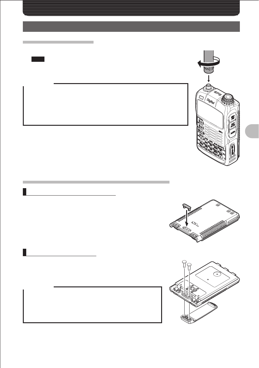
Installing the Antenna
1 Align the antenna with the antenna terminal on the main unit.
Note Be sure to hold the thick root of the antenna when installing it.
2 Turn the antenna clockwise until it is secured.
Precaution
zDo not hold the upper part of the antenna when installing or removing it.
Breaking of wire can occur inside the antenna.
zDo not transmit without installing the antenna. The transmitter circuit can
be damaged.
zWhen using an detachable antenna other than the supplied one or any
other external antenna, ensure that its SWR is adjusted to 1.5 or lower.
Attaching the Supplied Belt Clip/Protective Cap
Attaching the Protective Cap
1 Attaching the Protective Cap
If you do not use the belt clip, attach the protective cap
to the belt clip attaching opening.
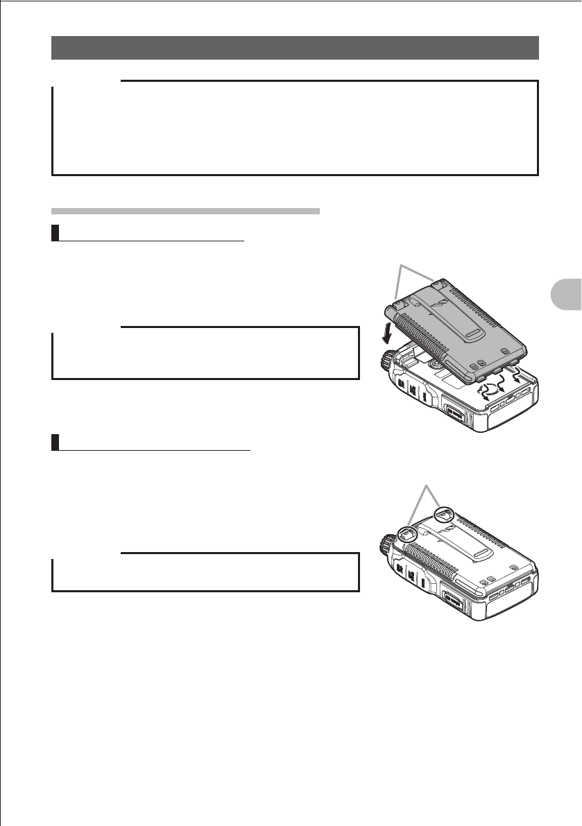
Installing the Belt Clip
1 Turn over the battery pack.
2 Install the belt clip using the supplied screws (two).
Precaution
zBe sure to use the supplied screws when installing the belt
clip. Using any other screws can result in injury, damage to
parts, and other troubles.
zBe sure to install the protective cap when the belt clip is not
used.
FCC ID: K6620445X20
IC: 511B-20445X20
YAESU MUSEN CO., LTD.
16
Basic Operation
Preparation
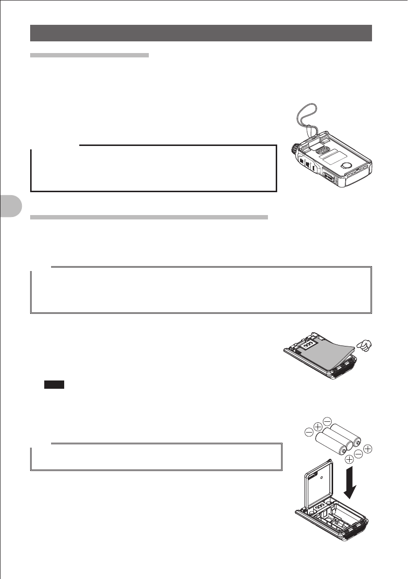
Attaching a Hand Strap
If you attach a hand strap to the FT1DR, its string which is inserted in and secured to
the strap hole in the transceiver must have a diameter of 1 mm.
* The hand strap does not come with the FT1DR.
1 Remove the battery pack.
2 Attach the hand strap.
Precaution
Use a hand strap which can stand the weight of the FT1DR.
If you use a hand strap which is not strong enough, the hand strap can
break and the FT1DR can fall down, resulting in injury, damage to parts,
and other troubles.
How to Use the Battery Case (FBA-39) (Option)
The optional battery case (FBA-39) allows three AA Alkaline batteries to be used as a
power supply.
Hint
When the battery case (FBA-39) is used, you can select a power output level from:
Low Power (L1): 0.05 W
Low Power (L2): 1W
Note that Low Power (L3) and High Power are not available.
1 Open the cover.
Lift up the lower right corner indicated by the hand pointer in
the illustration.
2 Put alkaline batteries in the battery case.
Note Use three alkaline batteries. Pay attention to polarities (+ and )
of the alkaline batteries.
3 Close the cover.
Push hard four corners of the cover to close it tightly.
Hint
When the batteries become weak, _ is displayed on the LCD. When
the batteries become far weaker, _ blinks on the LCD.
FCC ID: K6620445X20
IC: 511B-20445X20
YAESU MUSEN CO., LTD.
17
Basic Operation
Preparation
Precaution
zManganese batteries cannot be used. Rechargeable AA batteries cannot be used, either.
zDo not use new batteries along with old batteries. The life of new batteries can decrease.
zIf you do not use the FT1DR for a long period, remove the batteries from the battery case.
zIf the terminal or electrode of the battery case is dirty, the FT1DR can malfunction due to poor
contact, resulting in overheating or explosion. If the terminal or electrode gets dirty, clean it using a
dry cloth or cotton swab.
Installing/Removing the Battery Pack
Installing the Battery Pack
1 Insert the bottom tabs of the battery in the slots at
the bottom of the FT1DR.
2 Push in the lock knobs until they click.
Precaution
When you use the FT1DR for the first time after purchase or
you have not used it for a long period, charge the battery pack
before use.
Removing the Battery Pack
1 While pushing down the lock knobs, remove the
battery pack.
Push down the lock knobs in the direction of the arrow
shown in the illustration.
Precaution
When releasing the lock knobs, be careful not to hurt your
fingers and nails.
Lock knobs
Push down the lock knobs
in the direction of the arrow.
FCC ID: K6620445X20
IC: 511B-20445X20
YAESU MUSEN CO., LTD.
18
Basic Operation
Preparation
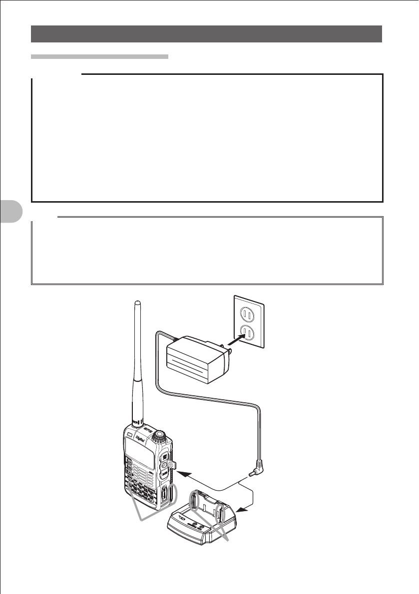
Charging the Battery Pack
Precaution
zThe battery pack is rechargeable about 300 times. However, improper use such as overcharge or
over-discharge can shorten its life.
zThe battery pack is a consumable item. Recharging the battery pack repeatedly will gradually
shorten the time until its power becomes low.
zIf the FT1DR is not used for a long period with the battery pack installed, deterioration of the battery
pack can accelerate.
zIf you do not use the FT1DR for a long period, be sure to store it with the battery pack removed.
Even if you do not use the FT1DR for a long period, install the battery pack biannually and recharge
the battery pack about 50%.
zStoring the battery pack in a high-temperature place can deteriorate it faster than usual.
Store the battery pack in a place where the ambient temperature is 20°C to +50°C.
zDo not drop or give a strong shock to the battery pack. It can break.
Hints
• The battery pack contains lithium-ion batteries that can be recharged for repetitive use.
• The FT1DR can be used with either of the following battery packs:
(1) Accessory: FNB-101L (I 7.4 V, 1100 mAh)
(2) Option: FNB-102L (I 7.4 V, 1800 mAh)
• When the battery pack is recharged, its output voltage (about 8 V) becomes higher than the
specified value (7.4 V). This is not a failure.
100 - 120 VAC
Battery charger
PA-48
(accessory)
Grooves in
battery pack
Rails
Quick-charge cradle CD-41
(option)
FCC ID: K6620445X20
IC: 511B-20445X20
YAESU MUSEN CO., LTD.
19
Basic Operation
Preparation
1 Install the battery pack.
2 Turn off the FT1DR.
3 Insert the plug of the battery charger (PA-48A) in the
EXT DC IN jack of the FT1DR.
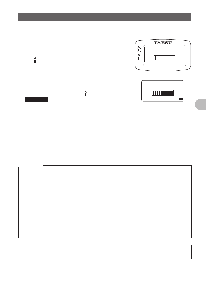
Charging starts.
The lamp glows red and “CHARGING” is displayed
on the LCD.
The charge level is indicated by a bar graph.
It takes about 5 hours to charge the battery pack fully.
When charging is completed, “COMPLETE” is
displayed on the LCD and the lamp glows green.
Supplement • It takes about 8 hours to charge the FNB-102LI
(option).
•
The optional quick-charge cradle (CD-41) requires about 2.5 hours to charge the
supplied battery pack (about 4 hours to charge the optional battery pack FNB-102LI).
Place the FT1DR on the cradle with the rails of the cradle fit in the grooves in the
battery pack.
When charging the battery pack using the cradle, the LED on the cradle indicate the
state of charging.
During charging: Red glow Fast blink Slow blink
Completion of charging: Green glow
4 Remove the plug of the battery charger from the jack of the FT1DR.
Precaution
zNeither transmission nor reception can be performed while charging the battery pack using the
supplied battery charger.
zDuring charging, noise may be generated in the nearby TV or radio.
Charge the battery pack with the battery charger away from the TV or radio as far as possible.
zIf “BATTERY NOT INSTALLED” is displayed on the LCD and the battery pack cannot be charged
after lapse of 11 or more hours, stop charging the battery pack immediately.
If the same message is displayed again, the battery pack is presumably at the end of its life or
defective.
If so, replace the battery pack with a new one.
zWhile charging the battery pack, protect the FT1DR from splash of water.
zCharge the battery pack in a place where the ambient temperature is +5C to +35C.
zIf the terminal or electrode of the battery case is dirty, the FT1DR can malfunction due to poor
contact, resulting in overheating or explosion. If the terminal or electrode gets dirty, clean it using a
dry cloth or cotton swab.
Hints
• The battery charger may become hot during charging. This is not a failure.
• If _ flashes, the battery pack charge is depleted. Charge it immediately.
CHARGING
COMPLETED
FCC ID: K6620445X20
IC: 511B-20445X20
YAESU MUSEN CO., LTD.
20
Basic Operation
Preparation
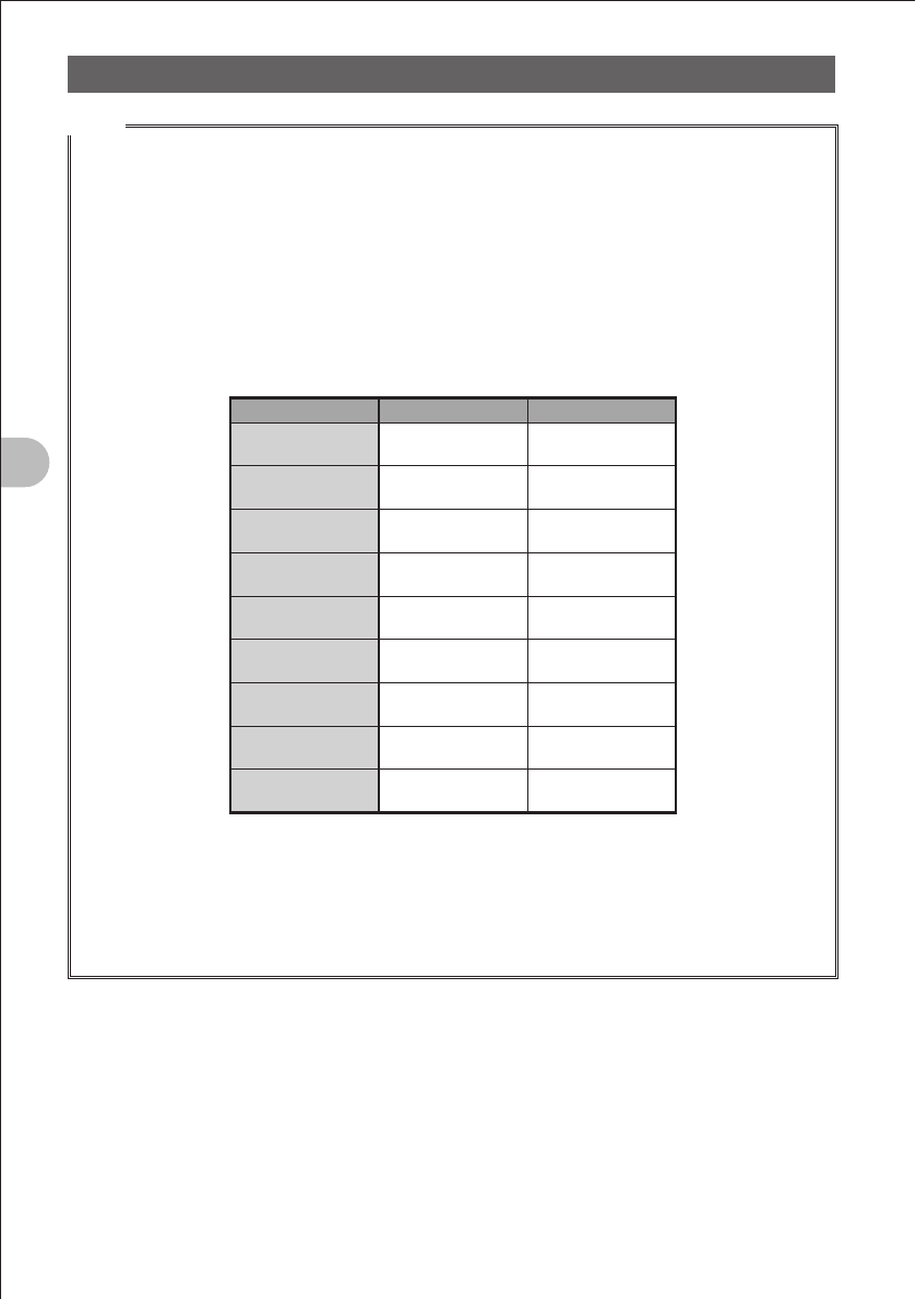
Approximate Operating Hours and Remaining Charge Level Indication
Approximate hours during which the fully charged battery pack or three new AA alkaline
batteries can operate the FT1DR are as follows:
Band
Battery
pack
FNB-101LI
Battery
pack
FNB-102LI
Batter case
FBA-39 Icon
Amateur radio
band
144 MHz
band
Approx. 5.0
hours
Approx. 8.5
hours
Approx. 17
hours
< : Full battery power
> : Enough battery power
? : Low battery power
_ : Poor battery power
Charge battery.
_ : Charge battery
immediately.
(Blink)
430 MHz
band
Approx. 5.0
hours
Approx.8.0
hours
Approx.16
hours
Remarks Approximate hours are estimated assuming that the FT1DR is operated under the
following conditions. Hours during which the FT1DR can be used actually vary depending
on use conditions, ambient temperature, etc.
•
The GPS function is deactivated.
• With an amateur radio band selected, a sequence in which high-power transmission
is performed for 6 seconds, reception is performed for 6 seconds, and the standby
operation is performed for 48 seconds is repeated.
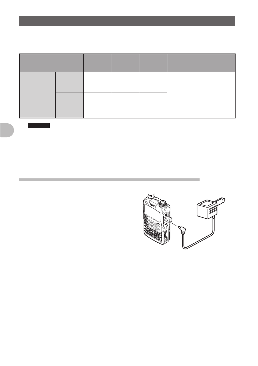
Connecting an External Power Supply for Use in Vehicle
The optional external power supply adapter with
a cigarette lighter plug (E-DC-5B) allows the
FT1DR to be used in a vehicle.
1 Turn off the FT1DR.
2 Insert the plug of the external power supply
adapter with a cigarette lighter plug (E-DC-
5B) in the EXT DC IN jack of the FT1DR.
3 Insert the cigarette lighter plug of the external
power supply adapter with a cigarette lighter
plug (E-DC-5B) in the cigarette lighter socket
of the vehicle.
To cigarette lighter socket
of vehicle
EXT DC IN jack
External power supply
adapter with
a cigarette lighter plug
E-DC-5B (option)
FCC ID: K6620445X20
IC: 511B-20445X20
YAESU MUSEN CO., LTD.
21
Basic Operation
Preparation
Precaution
zThe E-DC-5B is compatible with a 12 VDC cigarette lighter socket.
Do not connect the E-DC-5B to the 24 VDC cigarette lighter socket.
zUse the FT1DR at the minimum required transmission power level to prevent overheating.
zDo not perform continuous transmission for a prolonged period. The FT1DR can overheat, resulting
in a failure or burn.
zIf you operate the FT1DR for 7 hours or longer, it is recommended that you remove the battery pack
and install the optional battery case (FBA-39).
zRecharging the fully-charged battery pack repeatedly can shorten its life. Be extremely careful not to
do so when you operate the FT1DR using an external power supply.
zWhile charging the battery pack, protect the FT1DR from splash of water.
zCharge the battery pack in a place where the ambient temperature is +5C to +35C.
zIf the terminal or electrode of the battery case is dirty, the FT1DR can malfunction due to poor
contact, resulting in overheating or rupture. If the terminal or electrode gets dirty, clean it using a dry
cloth or cotton swab.
Hints
• The external power supply requires about 5 hours to charge the battery pack (about 8 hours
to charge the optional battery pack FNB-102LI). If the battery pack is charged with the FT1DR
powered, the charging time increases slightly.
• When the battery pack has been charged fully, charging stops automatically.
• The external power supply can be used with the battery case installed.
• If you connect the FT1DR to the extern al power supply with it turned off, “CONNECTED TO
EXTERNAL POWER” is displayed on the LCD, and about 20 seconds later “BATTERY NOT
INSTALLED” is displayed.
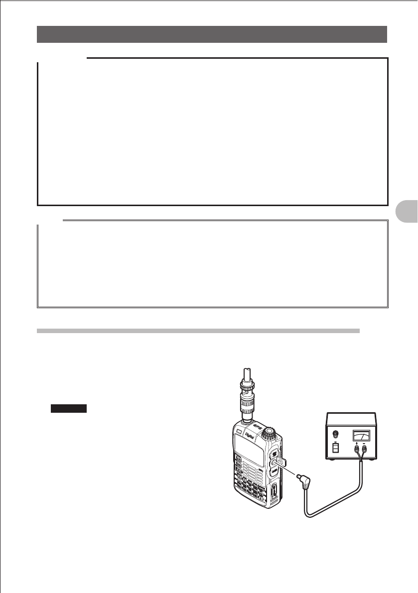
Connecting to an External Power Supply Using a Power Cable
The optional power cable (E-DC-6) allows the FT1DR to be connected to an external
power supply.
1 Turn off the FT1DR.
2 Connect the optional external power supply
cable (E-DC-6) to an external power supply.
Remarks • Connect the red/black wire or white/
black wire to the positive (+) terminal of
the external power supply, and connect
the black wire to the negative ()
terminal.
• Set the voltage of the external power
supply to 12-14 V.
3 Insert the plug of the external power supply
in the EXT DC IN jack of the FT1DR.
Connect the
external antenna.
External power supply
External power
supply cable
E-DC-6 (option)
FCC ID: K6620445X20
IC: 511B-20445X20
YAESU MUSEN CO., LTD.

22
Basic Operation
Preparation
Precautions
zWhen you use the FT1DR with the external power supply cable (E-DC-6) connected to an external
power supply, pay attention to the following:
• The power supply voltage must be 12 V to 14 V.
If the voltage exceeds 14 V, the high voltage protection function is activated to disable high-power
transmission. L3 (2.5 W) is selected automatically to reduce the transmission power.
If the voltage exceeds 16 V, failures such as damage to the electric circuits of the FT1DR can
result. Take extra care.
• Connect the red/black wire or white/black wire of the external power supply cable (E-DC-6) to the
positive (+) terminal of the external power supply, and connect the black wire to the negative ()
terminal.
• Use an external power supply having sufficient current capacity (3 A or more).
• If the supplied antenna remains installed, the external power supply can malfunction, resulting in a
failure. If you use an external power supply, remove the supplied antenna and connect an external
antenna. Place the external power supply sufficiently away from the FT1DR.
zUse the FT1DR at the minimum required transmission power level to prevent overheating.
zDo not continue transmission for a prolonged period. The FT1DR can overheat, resulting in a failure
or burn.
zIf you operate the FT1DR for 7 hours or longer, it is recommended that you remove the battery pack
and install the optional battery case (FBA-39).
zRecharging the fully-charged battery pack repeatedly can shorten its life. Be extremely careful not to
do so when you operate the FT1DR using an external power supply.
zWhile charging the battery pack, protect the FT1DR from splash of water.
zCharge the battery pack in a place where the ambient temperature is +5C to +35C.
zIf the terminal or electrode of the battery case is dirty, the FT1DR can malfunction due to poor
contact, resulting in overheating or explosion. If the terminal or electrode gets dirty, clean it using a
dry cloth or cotton swab.
Hints
• The external power supply requires about 5 hours to charge the battery pack (about 8 hours
to charge the optional battery pack FNB-102LI). If the battery pack is charged with the FT1DR
powered, the charging time increases slightly.
• The external power supply can be used with the battery case installed.
In this case, “BATTERY NOT INSTALLED” is displayed on the LCD of the FT1DR; however, the
FT1DR can be used, without any problem, with the battery case installed.
• If you connect the FT1DR to the external power supply with it turned off, “CONNECTED TO
EXTERNAL POWER” is displayed on the LCD, and about 20 seconds later “BATTERY NOT
INSTALLED” is displayed.
FCC ID: K6620445X20
IC: 511B-20445X20
YAESU MUSEN CO., LTD.
23
Basic Operation
Communication
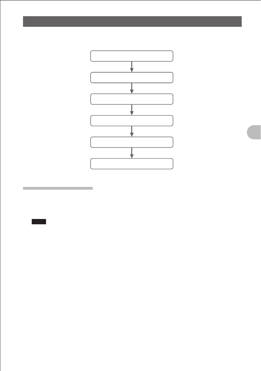
Let’s try communication using the FT1DR in the analog communication mode.
Follow the procedure below.
Turn the power on.
Adjust the volume level.
Select an operating band.
Select a frequency (band).
Tune in to a frequency.
Start communication.
Turning on the Power
1 Press and hold the P switch over 1 second.
An opening message is displayed, and then two frequencies (A-band frequency and
B-band frequency) are displayed at the same time.
Hints You can change the information such as the power supply voltage and the opening message
displayed at power-on. Press and hold the M key over 1 second to select the Set mode, and
then select “1 DISPLAY” “7 OPENING MESSAGE”.
In addition, you can cause the FT1DR to display the reception frequency immediately without
displaying the opening message (See page 154).
OTurning off the Power
To turn off the power, press and hold the P switch over 1 second.
FCC ID: K6620445X20
IC: 511B-20445X20
YAESU MUSEN CO., LTD.
24
Basic Operation
Communication
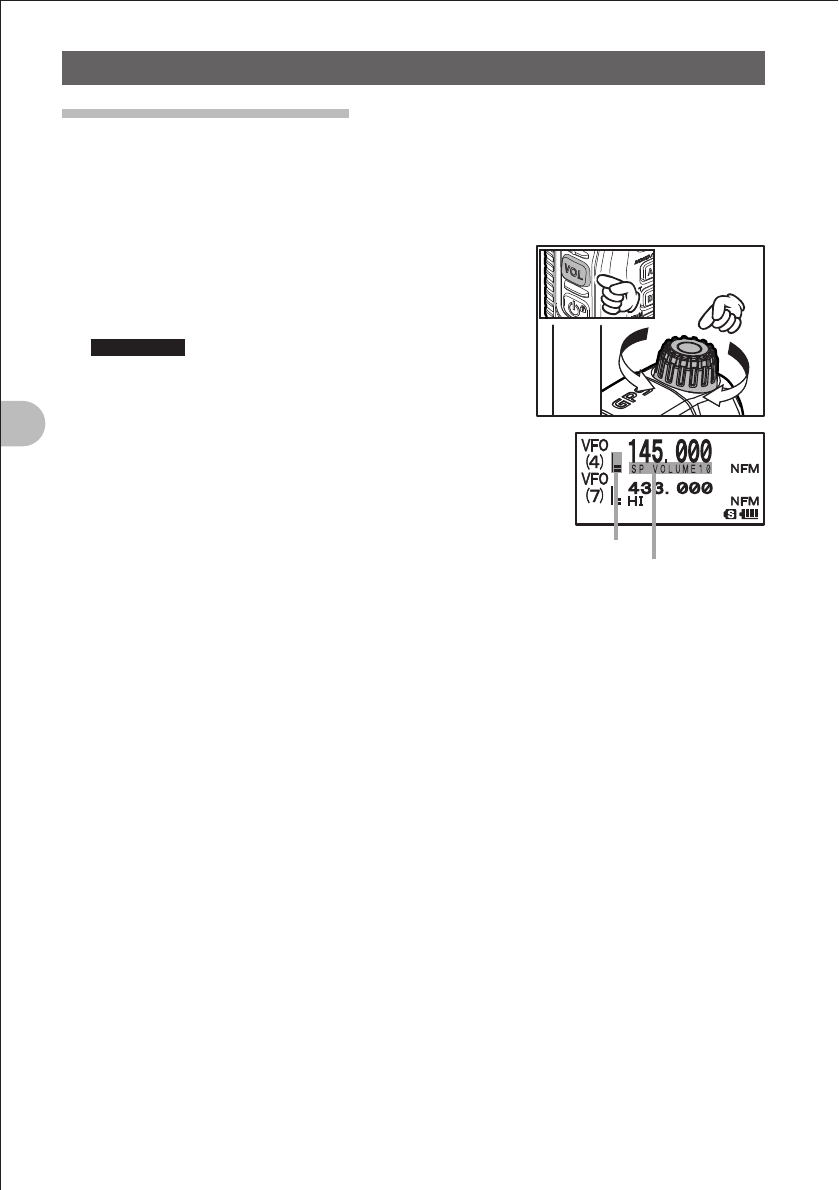
Adjusting the Volume Level
The FT1DR allows the volume level to be adjusted for the A-band and B-band
separately.
1 Press the A key to select a band for which you want to adjust the volume level.
Pressing the A key toggles between the A-band and B-band.
2 While pressing the v key, turn the O knob to
adjust the volume level.
The volume bar graph moves up/down while
blinking.
Supplement If no sound is heard from the speaker, press the
T key and then adjust the volume level while
listening to white noise.
3 Release the v key.
The Volume Level Adjustment mode is canceled.
Volume bar graph blinks.
One of SP VOLUME 0 to
SP VOLUME 32 is displayed.
FCC ID: K6620445X20
IC: 511B-20445X20
YAESU MUSEN CO., LTD.
25
Basic Operation
Communication
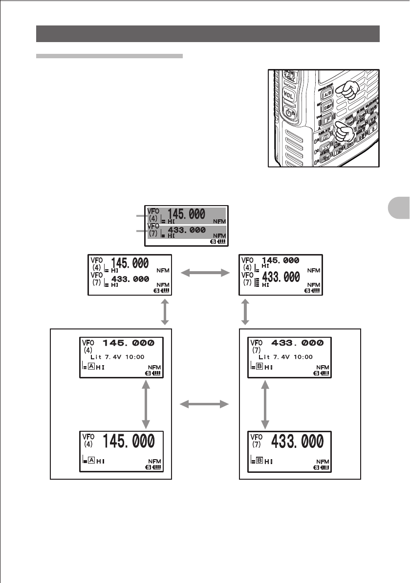
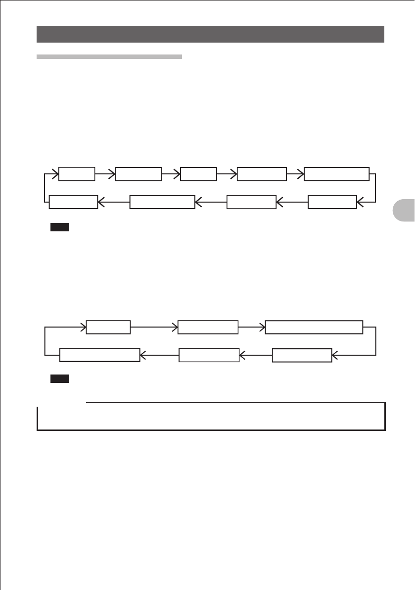
Selecting an Operating Band
The frequency displayed on the LCD in large letters is
called an operating band.
Each operating band allows you change the frequency
and perform transmission.
Pressing the A key briefly toggles between the information for A-band and the
information for B-band.
Press the
A key
briefly.
Press the
A key
briefly.
A-band (operating band)
B-band
Press the F key
briefly.
Press the A key
briefly.
Press the F key
briefly.
Press the A key
briefly.
Press and hold the A key
for about 1 second.
Press and hold the A key
for about 1 second.
FCC ID: K6620445X20
IC: 511B-20445X20
YAESU MUSEN CO., LTD.
26
Basic Operation
Communication
Hints
• The A-band allows you to perform communication using the following amateur radio bands.
144 MHz band, 430 MHz band
The A-band also allows you to perform reception using the following radio bands:
AIR band, INFO band (1), INFO band (2)
• The B-band allows you to perform communication using the following amateur radio bands.
144 MHz band, 430 MHz band
The B-band also allows you to perform reception using the following radio bands:
AIR band, INFO band (1)
• The number (1-9) corresponding to the selected frequency band is displayed on the LCD.
For the relationship between the numbers and frequency bands, see the following table:
Reception frequencies of A-band and B-band
Frequency band No.
A-band B-band
(1)
(2)
(3)
(4)
(5)
(6)
(7)
(8)
(9)
1.8 MHz to 30 MHz
(SW band)
30 MHz to 76 MHz
(50 MHz band)
108 MHz to 137 MHz
(AIR band)
137 MHz to 174 MHz
(144 MHz band)
174 MHz to 222 MHz
222 MHz to 420 MHz
(INFO band (1))
420 MHz to 470 MHz
(430 MHz band)
470 MHz to 770 MHz
770 MHz to 999 MHz
(INFO band (2))
108MHz to 137MHz
(AIR band)
137 MHz to 174 MHz
(144 MHz band)
174 MHz to 222 MHz
222 MHz to 420 MHz
(INFO band (1))
420 MHz to 470 MHz
(430 MHz band)
470 MHz to 770 MHz
• The A-band and B-band can be received at the same time.
You can receive an amateur radio frequency while listening to the AIR band, or receive two amateur
radio frequencies on the same frequency band at the same time (V+V/U+U: Dual frequency
reception on the same band).
• The sub-band operation function allows you to change the sub-band to the operating band during
dual reception (See page 29).
FCC ID: K6620445X20
IC: 511B-20445X20
YAESU MUSEN CO., LTD.
27
Basic Operation
Communication
Selecting a Frequency Band
The FT1DR allows you to select a frequency band for the A-band and a frequency band
for the B-band separately.
OSetting a Frequency Band for the A-band
1 Press the A key.
Select the A-band.
2 Press the B key briefly.
Select a frequency band.
SW band (1) 50 MH䡖㻌band (2) AIR band (3) 144 MHz band (4) 174 MHz to 222 MHz (5)
INFO band (1) (6)
430 MHz band (7)470 MHz to 770 MHz (8)INFO band (2) (9)
Hint Pressing the F key briefly and then pressing the B briefly changes frequency bands in
the reverse order.
OSelecting a Frequency Band for the B-band
1 Press the A key.
Select the B-band.
2 Press the B key briefly.
Select a frequency band.
AIR band (3) 144 MHz band (4) 174 MHz to 222 MHz band (5)
INFO band (1) (6)
430 MHz band (7)
470 MHz to 770 MHz (8)
Hint Pressing the F key briefly and then pressing the B briefly changes frequency bands in
the reverse order.
Precaution
zDigital communication can be performed only on the A-band.
Digital communication cannot be performed on the B-band.
FCC ID: K6620445X20
IC: 511B-20445X20
YAESU MUSEN CO., LTD.
28
Basic Operation
Communication
Hints
• The number (one of 1-9) corresponding to the selected frequency band is displayed on the LCD.
For the relationship between the numbers and the frequency bands, see the table shown on page
23.
• By default, the following frequencies are set.
A-band: 145.000 MHz B-band: 433.000MHz
• By default, the Auto mode is selected such that it is switched to the mode ideal for the selected
frequency band.
You can change modes by pressing and holding the M key over 1 second and then selecting “2
TX/RX” “1 MODE” “5RX MODE” (See page 29).
• For the relationship between frequency bands and reception frequencies, see the table on page 11.
• Pressing the F key and then pressing the 4 key allows you to call the home channel of each
frequency band (See page 40).
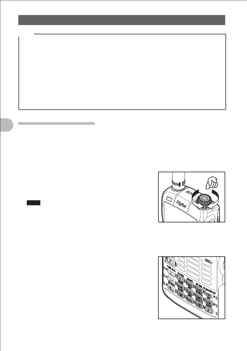
Tuning in to a Frequency
Tune in to your desired frequency using either of the following methods:
(1) Turn the O knob to tune in to your desired frequency.
(2) Enter a frequency directly using numeric keys.
OTurning the O knob to Tune in to a Desired Frequency
1 Select the VFO mode.
2 Turn the O knob to tune in to your desired
frequency.
Clockwise turn: The frequency increases.
Counterclockwise turn: The frequency decreases.
Hints Pressing the F key briefly and turning the O knob
allows you to set frequencies in steps of 1 MHz.
OEntering a Desired Frequency Directly Using Numeric Keys
1 Press the V key.
The VOF mode is selected, allowing you to select a frequency.
2 Enter your desired frequency using numeric keys.
Example: To enter 145.520 MHz, press the following
keys:
14552
Example: To enter 430.000 MHz, press the following
keys:
43V
FCC ID: K6620445X20
IC: 511B-20445X20
YAESU MUSEN CO., LTD.

29
Basic Operation
Communication
Hints
• By default, the Auto Step mode is selected such that the frequency step ideal for the reception
frequency is automatically selected.
You can change frequency steps manually using the O knob (See page 28).
• If you enter a wrong digit when entering a frequency using numeric keys, you can cancel it by
pressing the p switch.
• By default, turning the O knob beyond the selected frequency band causes the FT1DR to change
the selected frequency band to another frequency band.
To prevent this, press and hold the M key over 1 second to select the Set mode and then select
“7 CONFIG” “22 VFO MODE” “BAND”. The FT1DR can display frequencies on the same
frequency band repeatedly even if you turn the O knob beyond the selected frequency band.
Performing Communication
1 While pressing the p switch, speak into the microphone.
When speaking into the microphone, keep it about 5 cm away from your mouth.
2 Release the p switch.
The FT1DR returns to the Receive mode.
Precaution
zUse the FT1DR at the minimum required transmission power level.
Doing so prevents the FT1DR from overheating and saves battery power, increasing the operating
time.
zDo not continue transmission for a prolonged period. The FT1DR can overheat, resulting in a failure
or burn.
zIf transmission is continued for a long period, the FT1DR overheats and the overheat protection
function is activated, As a result, Low Power is automatically selected as the power output level. If
transmission is continued with the overheat protection function held active, the FT1DR is forcibly
returned to the Receive mode.
If you touch the FT1DR immediately after the overheat protection function has become active,
you can get burnt. Wait for the temperature inside the FT1DR to drop sufficiently before resuming
transmission.
zDo not perform transmission without installing the antenna. The transmitter circuit can be damaged.
FCC ID: K6620445X20
IC: 511B-20445X20
YAESU MUSEN CO., LTD.
30
Basic Operation
Communication
Hints
• In the NFM mode, you can transmit on the 144 MHz band or the 430 MHz amateur bands.
• Even when you are performing reception in the AM mode, pressing the p switch allows you to
perform transmission in the NFM mode.
• Pressing the F key and the pressing the 1 key allows you to change the transmission power
level.
Pressing the F key displays f on the LCD. Pressing the X key toggles between transmission
power levels.
The icon corresponding to the transmission power level and a PO meter are displayed on the LCD.
The current power level is displayed, for about 2 seconds, in the area where a frequency is
displayed.
Transmission power is different between the battery pack and the battery case.
For more details, see “Changing the Transmission Power Level” on page 27.
• If the p switch is pressed when a band other than the amateur radio band is selected, an alarm
tone (beep) is issued and “ERROR” is displayed on the LCD, disabling transmission.
• Pressing the M key over 1 second to change the Set mode allows you to use the FT1DR more
conveniently.
Selecting “7 CONFIG” “2 BCLO” prohibits transmission during reception of a signal.
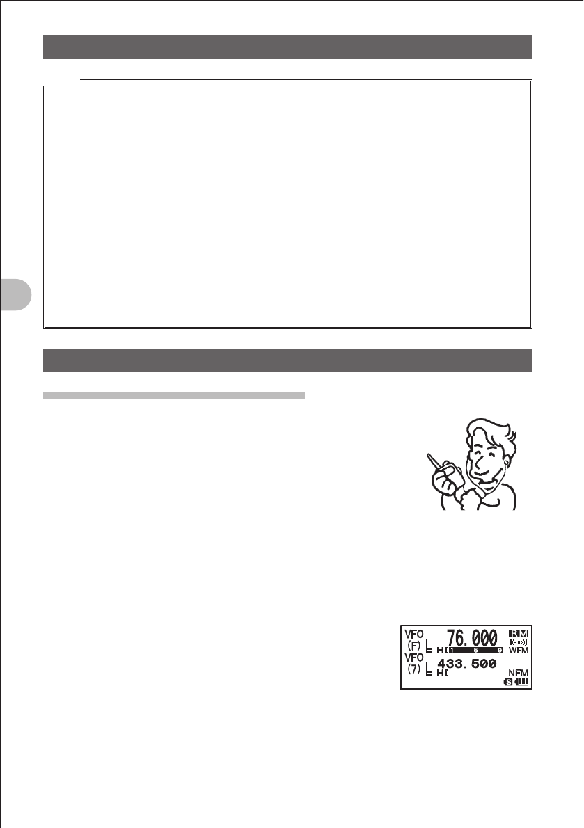
Listening to the Radio
Listening to an AM or FM Broadcast
The FT1DR allows you to receive AM (medium wave band) and
FM broadcasts on the A-band.
The FT1DR incorporates an antenna dedicated to the AM
broadcast (medium wave band).
Turn around the FT1DR body to adjust the AM broadcast
(medium wave band) receiving sensitivity.
The FM broadcast is received via the supplied antenna installed
at the top of the FD-D1.
1 Press the A key.
Select the A-band as an operating band.
2 Press the F key briefly, and then press the 0 key.
The Radio Function mode is selected.
3 Press the B key.
Pressing the B key toggles between AM and FM
broadcasts.
AM broadcast (middle wave band) (A) FM broadcast (F)
During reception of the AM broadcast (middle wave band),
(A) is displayed on the LCD.
During reception of the FM broadcast, (F) is displayed on the LCD.
4 Turn the O knob to tune in to your desired frequency.
Tune in to the frequency of your desired broadcast station.
FCC ID: K6620445X20
IC: 511B-20445X20
YAESU MUSEN CO., LTD.
31
Basic Operation
Listening to the Radio
To deactivate the radio function
1 Press the F key briefly, and then press the 0 key.
The Radio Function mode is canceled.
To scan through the radio band
1 Select the A-band as an operating band.
Press and hold the B key over 1 second.
If a signal is received during scanning, a beep sound is issued and scanning stops to
receive the broadcast corresponding to the received signal.
Five seconds later, scanning will resume.
While the broadcast is being received after stop of scanning, the decimal point
blinks.
Pressing the B key allows you to stop scanning.
Precaution
zWhen the MIC/SP jack is used, protect the FT1DR from splash of water.
Hints
• Frequencies of the broadcast stations you listen to frequently can be stored in the memory ( P.39).
• The AF-DUAL function allows you to monitor amateur band frequencies and memory channels while
listening to a radio broadcast. When a signal is received in an amateur band, the radio broadcast
audio is muted automatically so that you can perform communication hearing only the amateur band
audio (See page 121).
Switching between AM Antennas
You can switch between AM antennas while listening to an AM broadcast.
Switch between antennas according to the use conditions.
During normal use, you need not switch between AM antennas.
1 Press and hold the M key over 1 second.
The Set mode is selected.
2 Turn the O knob to select “2 TX/RX”.
3 Press the M key briefly.
4 Turn the O knob to select “1 MODE”.
5 Press the M key briefly.
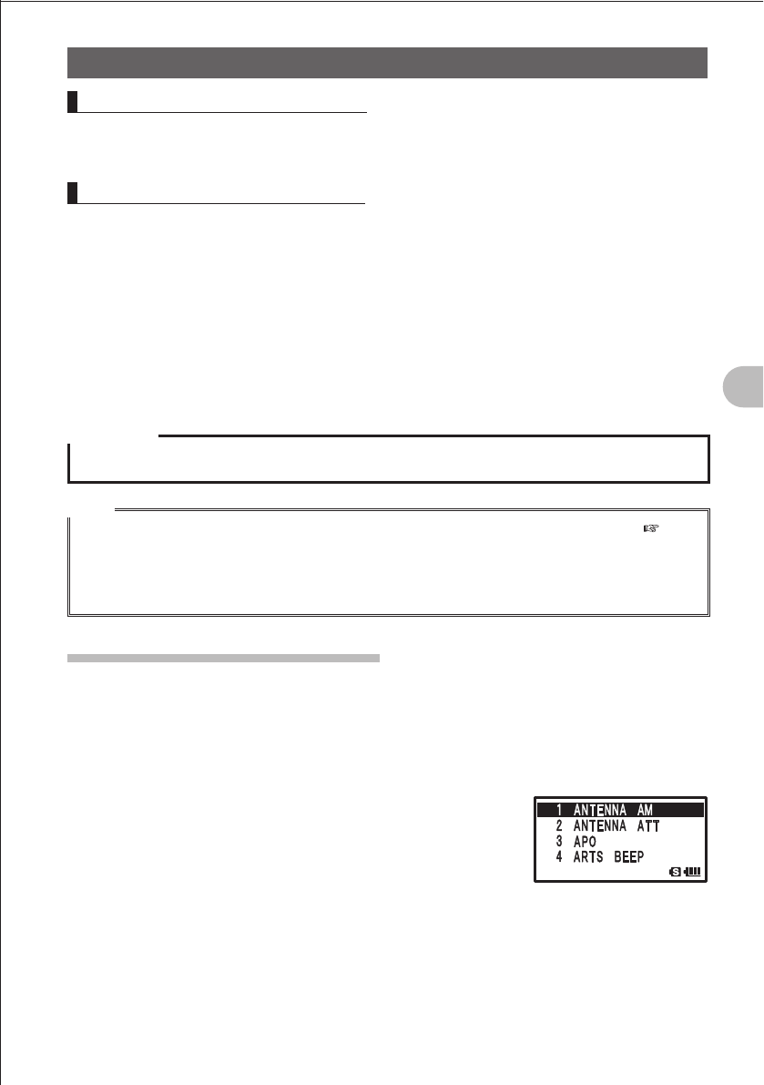
6 Turn the O knob to select “1 ANTENNA AM”.
7 Press the M key briefly.
FCC ID: K6620445X20
IC: 511B-20445X20
YAESU MUSEN CO., LTD.
32
Basic Operation
Listening to the Radio
8 Turn the O knob to switch to the desired antenna.
Display Operation
BAR & EXT.
ANTENNA
Switches between the whip antenna provided
at the top of the FT1DR and the built-in bar
antenna to receive AM broadcasts.
BAR ANTENNA When the AM broadcast is received, the whip
antenna is automatically switched to the built-
in bar antenna.
Turn around the FT1DR body to adjust the
AM broadcast (middle wave band) receiving
sensitivity.
9 Press the M key over 1 second.
The Set mode is canceled.
Miscellaneous Settings
Setting the Date and Time
The FT1DR incorporates a clock. The clock is used not only to display the time but also
turn on/off the FT1DR at the specified time (timer function). Set the clock before using
the FT1DR for the first time.
1 Press the M key over 1 second.
The Set mode is selected.
2 Turn the O knob to select “7 CONFIG”.
3 Press the M key briefly.
4 Turn the O knob to select “19 DATE & TIME ADJ”.
5 Press the M key briefly.
6 Turn the O knob to set the year.
7 Press the B key.
The cursor moves to the month.
8 Turn the O knob to set the month.
9 Repeat steps 5 and 6 to set the day, day of week, hour, and minute.
Pressing the % key moves the cursor to the setting item shown on the left.
Remarks The hour is displayed according to the 24-hour clock.
Next, set the time signal alarm.
If you do not want to set the time signal alarm, proceed to step 3 described in “Setting
the Time Signal Alarm”.
FCC ID: K6620445X20
IC: 511B-20445X20
YAESU MUSEN CO., LTD.

33
Basic Operation
Miscellaneous Settings
Setting the Time Signal
Set the time signal (a time signal tone is issued at 00 minute of each hour) as required.
1 Press the B key.
The cursor moves to “”.
2 Turn the O knob to select “TIME SIGNAL”.
Selecting “TIME SIGNAL” allows you to hear a time signal tone (beep) at 00 minute
of each hour.
If you do not want to hear the time signal tone, leave “” as it is.
3 Press the B key.
The cursor moves to “SET”.
4 Press the V key briefly.
The setting is determined.
5 Press the M key over 1 second.
6 Press theM key over 1 second again.
The Set mode is canceled.
Remarks When “MONOBAND RECEPTION” is selected, the current time is displayed on the LCD.
Hints
• The accuracy of the clock is 30 seconds/month. However, it may vary depending on the use
conditions such as the temperature.
• The FT1DR incorporates a rechargeable lithium battery dedicated to the clock.
Normally, the FT1DR is powered from the battery pack. When the battery pack is detached or runs
out, the lithium battery starts operating automatically. The lithium battery can operate the clock for
about 2 months.
• When you use the FT1DR for the first time or by attaching the battery pack which has been
detached for a long period, the accuracy of the clock may be poor. In such a case, detach the
battery pack temporarily, reattach it, and then adjust the time.
• When the FT1DR is operating in “Mono” band, the current time is displayed on the LCD. However,
when display of double-size characters or dual display is selected, the current time is not displayed
on the LCD.
• The calendar covers all dates from January 1, 2000 through December 31, 2099.
• Setting the APRS Set mode “17 GPS TIME SET” to AUTO will display the exact time automatically.
• The timer function allows you to turn off the FT1DR automatically (See page 149).
Also, you can turn on the power at the specified time (See page 149).
Muting Audio
If it is hard to hear the sound of the A-band and the sound of the B-band at the same
time, you can mute the sound of the operating band which is not selected now.
1 Press the M key over 1 second.
The Set mode is selected.
2 Turn the O knob to select “2 TX/RA”.
3 Press the M key briefly.
FCC ID: K6620445X20
IC: 511B-20445X20
YAESU MUSEN CO., LTD.
34
Basic Operation
Miscellaneous Settings
4 Turn the O knob to select “3 AUDIO”.
5 Press the M key briefly.
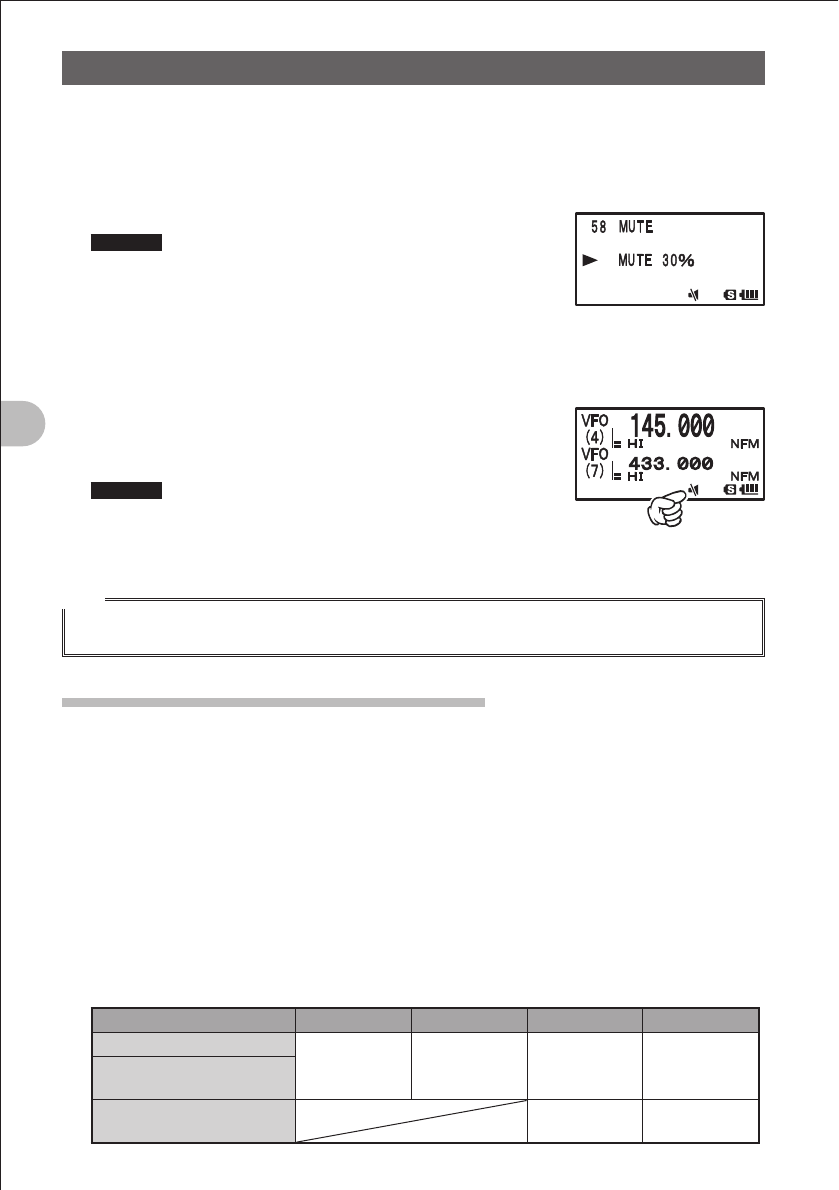
6 Turn the O knob to select “2 MUTE”.
7 Press the M key briefly.
8 Turn the O knob to select a muting level.
Remarks You can select one of the following four muting levels:
• MUTE 30%
• MUTE 50%
• MUTE 100%
• OFF
The larger the value, the smaller the sound.
To deactivate the muting function, select OFF.
9 Press the M key over 1 second.
10 Press theM key over 1 second again.
The Set mode is canceled.
Remarks When the muting function is activated, the ] icon is
displayed on the LCD.
When the muting function is being performed (sound is
being muted actually), the ] icon blinks on the LCD.
Hint
• When no signal is received on the operating band even if the muting function is activated, sound is
not muted.
Changing the Transmission Power Level
The maximum transmission power of the FT1DR is 5 W. When communicating with a
friend in the immediate area or you want to suppress battery power consumption, you
can lower the transmission power. For power supply types and transmission power
levels, see the table shown below.
1 Press the F key briefly, and the press the 1 key briefly.
f is displayed on the LCD.
Select your desired transmission power level while f is displayed. The icon and
PO meter which correspond to the selected transmission power level appear.
The current power level is displayed, for about 2 seconds, in the area where a
frequency is displayed.
Example: HIGH POWER
Battery type
H (High power)
L3 L2 L1
Battery pack
5W 2.5W 1W 0.05W
External power supply
(13.8 VDC)
Battery case
(alkaline batteries) 1W 0.05W
FCC ID: K6620445X20
IC: 511B-20445X20
YAESU MUSEN CO., LTD.
35
Basic Operation
Miscellaneous Settings
Hints
• You can set a transmission power level separately for the A-band and B-band.
• Use the FT1DR at the minimum required transmission power level to suppress battery power
consumption.
• By default, “HI (High power)” is selected.
Adjusting the Squelch Level
You can mute the raspy noise heard when no signal is being received. The squelch level
can be adjusted separately for two broadcasts (NFM and AM) received on the A-band
and B-band. When the squelch level is increased, the noise is more liable to disappear
but, in some cases, it becomes difficult to receive weak signals. Adjust the squelch level
as required.
1 Press the A key.
Select the target operating band.
2 Press the F key briefly, and then press the T key.
3 Turn the O knob to adjust the squelch level.
Remarks • The squelch level can be adjusted within the range from 0 to 15.
• Default: LEVEL 1
4 Press the T key.
The Squelch Level Adjustment mode is canceled.
Hint
While the T key is held pressed, the squelch function can be deactivated for both the A-band and
B-band.
Changing the Frequency Step Manually
By default, “AUTO (Step)” is selected so that the optimum frequency step is
automatically selected according to the received frequency. You can change this
frequency step manually.
1 Press the M key over 1 second.
The Set mode is selected.
2 Turn the O knob to select “7 CONFIG”.
3 Press the M key briefly.
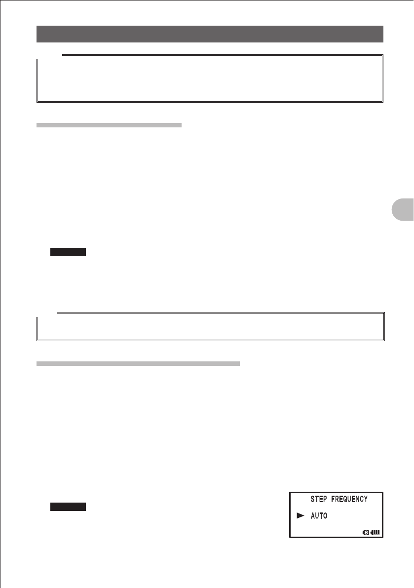
4 Turn the O knob to select “18 STEP”.
5 Press the M key briefly.
6 Turn the O knob to select your desired frequency step.
Remarks Selectable frequency steps are as follows:
· AUTO · 5 KHz · 6.25 KHz
· (8.33 KHz) · 10 KHz · 12.5 KHz
· 15 KHz · 20 KHz · 25 KHz
· 50 KHz · 100KHz
It is recommended that AUTO be selected normally.
Default: AUTO
FCC ID: K6620445X20
IC: 511B-20445X20
YAESU MUSEN CO., LTD.
36
Basic Operation
Miscellaneous Settings
7 Press the M key over 1 second.
8 Press the M key over 1 second again.
The Frequency Step Setting mode is canceled.
Hints
• For the AIR band (108 MHz to 136.991 MHz), the frequency step “8.33 kHz” can be selected.
• For bands covering 250MHz to 300MHz and bands covering 580 MHz or higher frequencies,
frequency steps “5 kHz”, “6.25 kHz”, and “15 kHz” cannot be selected.
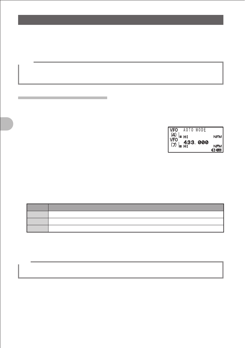
Changing the Mode Manually
By default, “AUTO (Auto Mode)” is selected so that the optimum mode (radio wave type)
is automatically selected according to the selected band (frequency band). You can
change this mode manually.
1 Press the M key over 1 second.
The Set mode is selected.
2 Turn the O knob to select “2 TX/RX”.
3 Press the M key briefly.
4 Turn the O knob to select “1 MODE”.
5 Press the M key briefly.
6 Turn the O knob to select “5 RX MODE”.
7 Press the M key briefly.
8 Turn the O knob to select your desired mode.
It is recommended that AUTO be selected normally.
Display Operation
AUTO The optimum mode is automatically selected according to the frequency band.
NFM Only the selected band is switched to the NFM (FM mode).
AM Only the selected band is switched to the AM mode.
9 Press the M key over 1 second three times.
The Set mode is canceled.
Hint
• Even if the AM mode is selected on an amateur band, 144 MHz band or 430 MHz band,
transmission takes place in the FM mode.
FCC ID: K6620445X20
IC: 511B-20445X20
YAESU MUSEN CO., LTD.
37
Basic Operation
Miscellaneous Settings
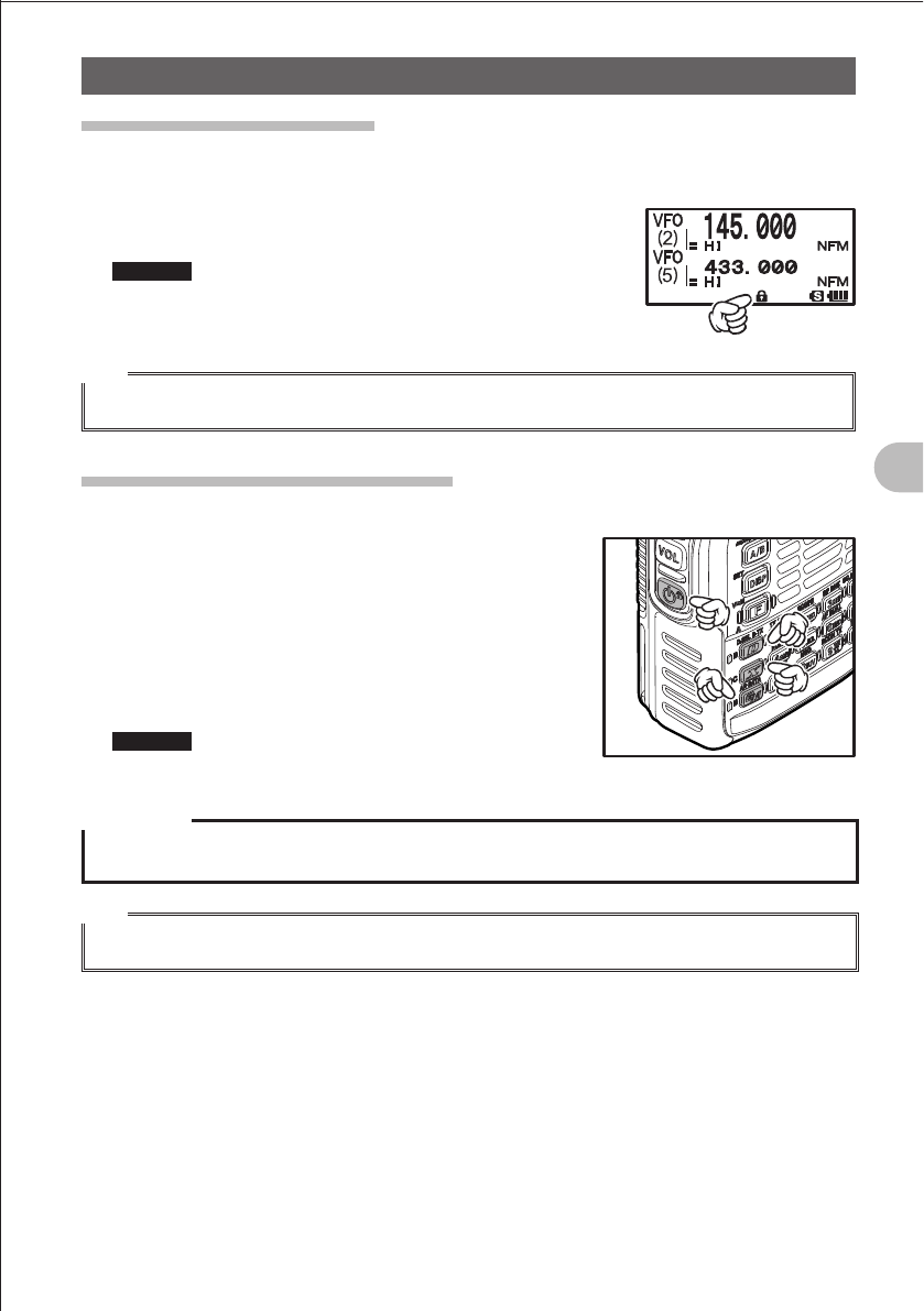
Locking keys or switches
To prevent accidental frequency change during operation, keys and switches other than
the PTT switch, T key, v key, P switch, and dial knob can be locked.
1 Press the P key briefly.
l is displayed on the LCD.
Remarks To release the lock, press the P key briefly gain.
l disappears from the LCD.
Hint
• You can also lock the dial knob and PTT switch by selecting the Set mode “46 LOCK”.
Restoring to Defaults (All Reset)
You can restore all settings and memory contents of the FT1DR to defaults.
1 While pressing the %, D, and X keys, press
the P switch.
The FT1DR is turned on, followed by beep.
When you hear the beep, release the keys.
2 When “ALL RESET PUSH F KEY!” appears on the
LCD, press the F key.
Beep is issued again.
Remarks To cancel the All Reset function, press a key or
switch other than F.
Precaution
When the All Reset function is performed, all data stored in the memory is deleted. Be sure to record it
on paper, etc. before performing the All Reset Function.
Hint
Also, you can restore only the settings configured in the Set mode to defaults (See page 168).
FCC ID: K6620445X20
IC: 511B-20445X20
YAESU MUSEN CO., LTD.
38
Repeater Operation
Repeater OperationRepeater Operation
Repeater Operation
Communicating Via the Repeater
The FT1DR supports an ARS (Automatic Repeater
Shift) function which allows you to perform
communication automatically just by setting the
reception frequency to the repeater frequency.
1 Set the reception frequency to the repeater
frequency.
“TN
” is displayed in the upper right corner of the
LCD.
2 While pressing the p switch, perform transmission.
Hints
• Pressing the F key, and then pressing the 5 key. This produces the “reverse” state where the
transmission frequency and the reception frequency are temporarily reversed, allowing you to check
whether you can communicate with the remote station directly.
• In the “reverse” state, blinks on the LCD.
• Press the F key, and then press the 5 key again. This cancels the “reverse” state.
• Press and hold the M key over 1 second to change the Set mode. This allows you to use the
repeater more conveniently.
“7 CONFIG” “14 RPT ARS” You can deactivate the ARS function.
“7 CONFIG” “15 RPT SHIFT” You can set the repeater shift direction.
“7 CONFIG” “16 RPT SHIFT FREQ” You can change the repeater shift step.
FCC ID: K6620445X20
IC: 511B-20445X20
YAESU MUSEN CO., LTD.
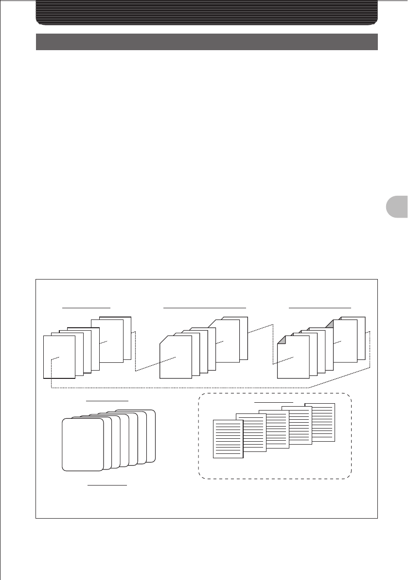
39
Using the Memory
Using the Memory
A Wide Variety of Memory Functions
The FT1DR provides the following various types of memory channels in addition to the
regular memory channels (memory numbers 1 to 900).
• “Home channels” which can be recalled on each frequency band with one touch of
a key. (See page 40)
• “Special banks” such as a international VHF (marine) radios (57 channels).
• 99 (901 to 999) “skip search memory channels” that allow you to skip unwanted
frequencies during VFO scanning (See page 57)
• 50 sets of “memory channels (L01/U01 to L50/U50) for programmable memory
scanning (PMS)” (See page 62)
An operating frequency, operation mode (type of radio), and other operational
information can be stored for each regular memory channel, home channel, or PMS
memory channel.
• Operating frequency • Operation mode • Memory tag
• Repeater information • Tone information • DCS information
• Memory skip information • Transmission power
Memory channels can be sorted out with them assigned to memory banks according to
the intended use. The FT1DR allows you to use 24 types of memory banks. A maximum
of 100 memory channels can be assigned to each memory bank.
900
899
4
3
2
1
L50/U50
L49/U49
L4/U4
L3/U3
L2/U2
L1/U1
904
903
902
901
999
998
Memory Configuration of FT1DR
• Memory channels for international VHF (marine) radios
(57 channels)
Memo ry ch ann el s
(900 channels)
Ski p search memo ry ch an n els
(99 channels)
Memo ry ch ann el s PMS
(50 set s)
Home ch an n el s
(7 channels)
Memo ry b anks
(24 banks)
Up to 100 channels can be
memorized on each band.
Aviation radio
band
430 MHz band
144 MHz band
VHF band
UHF band
Information radio band (1)
Information radio band (2)
Sp eci al b an ks
FCC ID: K6620445X20
IC: 511B-20445X20
YAESU MUSEN CO., LTD.
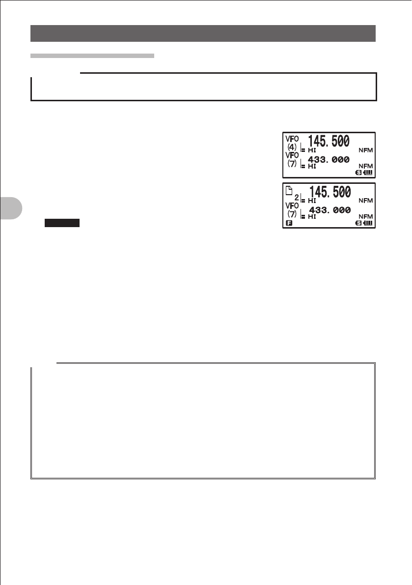
40
Using the Memory
A Wide Variety of Memory Functions
Writing into the Memory
Precaution
The stored data can be erased due to wrong operation, static electricity, or electrical noise.
Also, it can be erased in the case of a failure or repair. Be sure to write it down on paper or the like.
The FT1DR allows you to use 900 channels (memory channel numbers 1 to 900).
1 Select the VFO mode.
2 Turn the O knob to select a frequency.
Select the frequency you want to write into the memory.
3 Press the F key more than 1 second.
The Memory Write mode is selected, and the number of
the memory channel next to the memory channel for which
you stored a frequency last blinks.
Remarks • To cancel the memory write operation, press the p
switch.
• To store a frequency with a memory channel specified, turn the O knob to select the
memory channel
[The specified channel is unregistered] ( icon is displayed, and the memory channel
blinks.
[The specified channel is registered] ) icon is displayed, and “OVERWRITE OK?” is
displayed on the LCD.
• Pressing the M key allows you to skip channels quickly in steps of 100 channels.
4 Press the F key briefly.
The memory write operation is completed, and the registered frequency is displayed
on the LCD.
Hints
• By default, 145.000MHz was registered to memory channel 1. It can be changed to another
frequency, but cannot be deleted.
• The frequency which has previously been registered to a memory channel can be overwritten with a
new frequency.
When you intend to write a new frequency into the memory, an unregistered memory channel is
displayed.
• To display the lowest unregistered memory number when you start writing into the memory, press
the M key more than 1 second to select the Set mode, and then select “3 MEMORY” “6
MEMORY WRITE”.
• To inhibit writing into all memories, press the M key more than 1 second, and then select “3
MEMORY” “4 MEMORY PROTECT”.
FCC ID: K6620445X20
IC: 511B-20445X20
YAESU MUSEN CO., LTD.
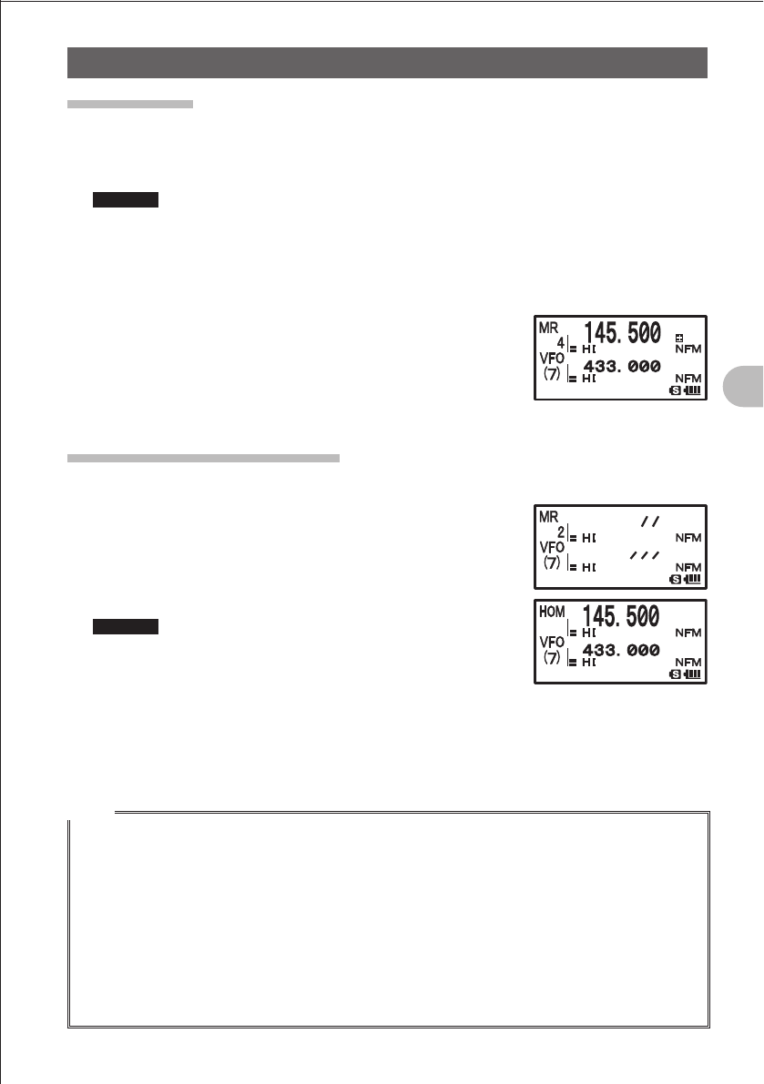
41
Using the Memory
A Wide Variety of Memory Functions
Split Memory
Two different frequencies, one for reception and other for transmission, can be
registered to a memory channel.
1 Write a reception frequency into the memory.
Remarks Write the reception frequency with reference to “Writing Data into Memories” above.
2 Select a transmission frequency in the VFO mode.
3 Press the F key more than 1 second.
4 Turn the O knob to select a channel number.
Select the channel number of which you registered a reception frequency.
5 While pressing the p switch, press the F key briefly.
When you recall the memory channel of which you
registered two different frequencies, one for reception and
the other for transmission, the @ icon is displayed on the
LCD.
Recalling a Memory Channel
Recall a registered memory channel in the following procedure:
1 Press the V key.
The Memory mode is selected, and the memory channel
you used last is displayed on the LCD.
2 Turn the O knob to select a memory channel.
Select the memory channel to use next.
Remarks • You can directly recall a memory channel using numeric
keys.
To recall memory channel 15:15V
• Pressing the F key briefly and turning the O knob
allows you to skip channels quickly in step of 10 channels.
3 Press the V key.
The Memory mode is canceled, and the frequency selected in the VFO mode is
displayed.
Hints
• Unregistered memory channels are skipped.
• By default, the priority memory channel used as the priority channel for the dual receive function
was set to the memory channel 1. “P” is displayed at the upper right of the memory channel number
(See page 128).
• The memory content can be transferred to the VFO of the operating band in the following procedure:
Press the F key for 1 second. Press the V key. “OVERWRITE OK?” is displayed. Press
the V key.
• Selecting the Memory Only mode in the following procedure allows you to use only memory
channels.
While pressing the V key, press the P key.
To cancel the Memory Only mode, press the V key again while pressing the P key (See page 155).
䠍䠐䠑䠊䠑䠌䠌
䠍䠐䠑䠊䠑䠌䠌
䠐䠏䠏䠊䠌䠌䠌
䠐䠏䠏䠊䠌䠌䠌
FCC ID: K6620445X20
IC: 511B-20445X20
YAESU MUSEN CO., LTD.
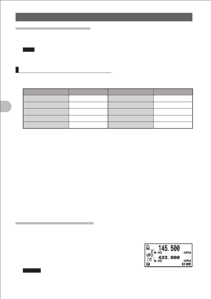
42
Using the Memory
A Wide Variety of Memory Functions
Recalling the Home Channel
1 Press the F key briefly.
The home channel of the currently selected frequency band is displayed on the LCD.
Hints • For the relationship between the frequency bands and the home channel frequencies, see
the table on the next page.
• Selecting a frequency by turning the O key allows you to return to the VFO mode.
Returning to the Previous Frequency
1 Press the F key briefly.
The frequency used before recalling the home channel is displayed on the LCD.
Frequency band Frequency Frequency band Frequency
Shortwave band [1] 1.800 MHz Information radio (1) [6] 380.000 MHz
50 MHz [2] 51.000 MHz 430 MHz band [7] 433.000 MHz
Aviation radio [3] 108.000 MHz
470 to 770 MHz band [8]
481.750 MHz
144 MHz band [4] 145.000 MHz Information radio (2) [9] 860.000 MHz
174 to 222 MHz band [5] 175.750 MHz
OChanging a Home Channel Frequency
You can change a default home channel frequency.
1 Select the VFO mode.
2 Turn the O knob to select a frequency.
Select a frequency to change.
3 Press the F key more than 1 second.
The Write mode is selected.
4 Press the X key briefly.
“OVERWRITE OK?” is displayed on the LCD for about 5 seconds.
5 Press the X key briefly.
When the new frequency has been written, the home channel frequency of the
selected frequency band is changed.
Deleting the Memory Channel
1 Select the Memory mode.
2 Press the F key more than 1 second.
3 Turn the O key to select the memory channel to delete.
4 Press the D key briefly.
“CLRAR OK?” is displayed on the LCD for about 3
seconds.
Remarks Pressing the F key allows you to cancel the memory
channel deletion operation.
FCC ID: K6620445X20
IC: 511B-20445X20
YAESU MUSEN CO., LTD.
43
Using the Memory
A Wide Variety of Memory Functions
5 Press the D key briefly.
The memory channel is deleted.
Remarks To delete other memory channels, repeat steps 2-5.
Precaution
zMemory channel 1 cannot be deleted.
Hint
The memory channel specified as a priority memory channel cannot be deleted. Before deleting it,
specify another memory channel as a priority memory.
Restoring the Deleted Memory Channel
You can restore a deleted memory channel.
1 Select the Memory mode.
The memory channel used last is displayed.
2 Press the F key more than 1 second.
3 Turn the O knob to select the memory channel to restore.
4 Press the D key briefly.
The deleted memory channel is restored.
Using Memory Banks
Registered memory channels can be sorted out according to the intended use. The
FT1DR allows you to use 24 types of banks. A maximum of 100 memory channels can
be assigned to each memory bank.
One memory channel can be registered in two or more memory banks. If the memory
channel registered in the memory bank is changed or updated, the content of the
corresponding memory channel in the memory bank is automatically changed or
updated.
E
E
E
E
E
E
E
E
E
a
a
a
a
a
a
a
a
a
E a
E a
a
0+]
0+]
0+]
0+]
0+]
0+]
a
Memory channel Memory bank
144MHz band is registered.
430MHz band is registered.
Amateur bands are registered together.
AIR band is registered.
FCC ID: K6620445X20
IC: 511B-20445X20
YAESU MUSEN CO., LTD.
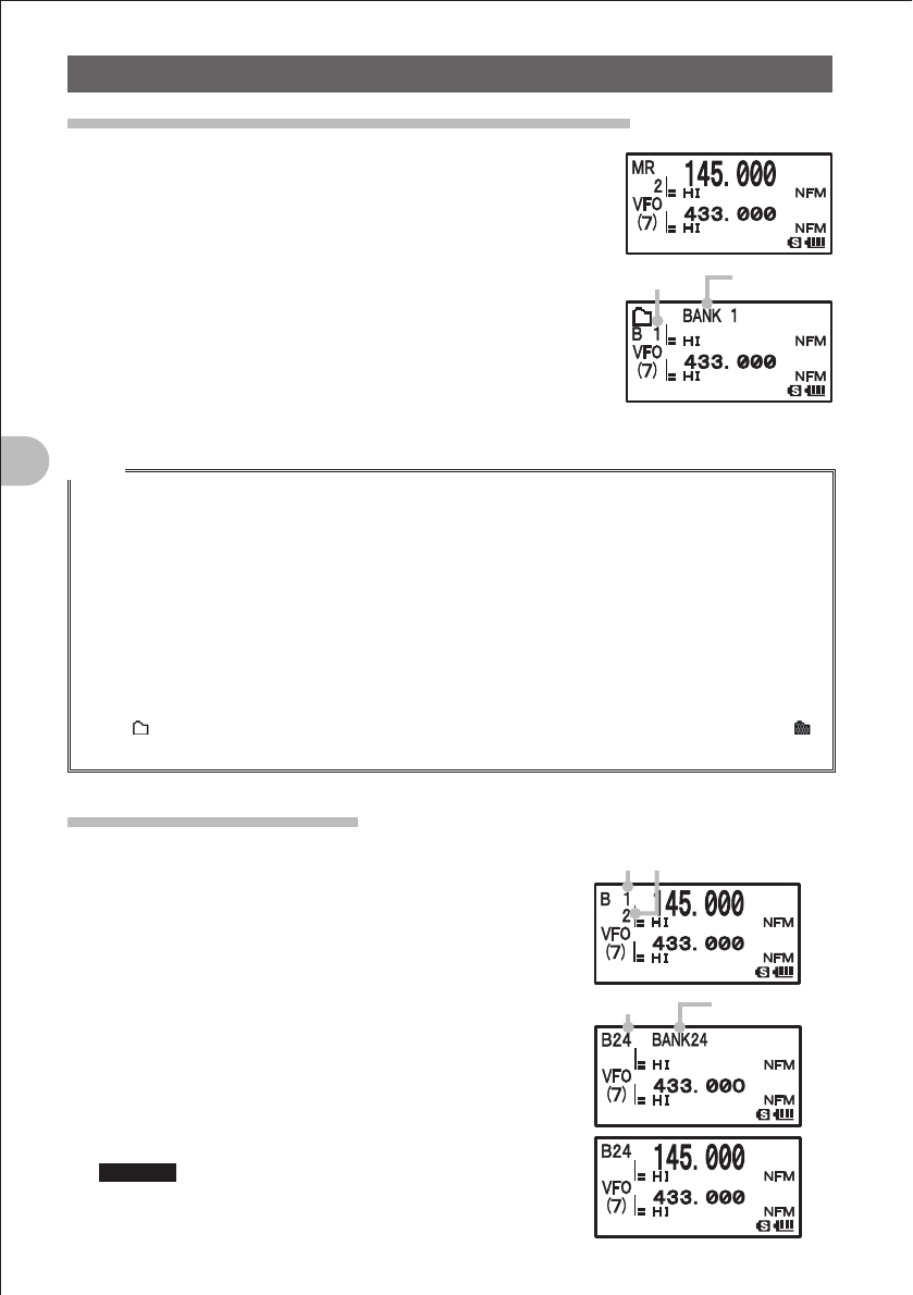
44
Using the Memory
Using Memory Banks
Registering a Memory Channel in a Memory Bank
1 Select the Memory mode.
2 Turn the O knob to select a memory channel.
Select the memory channel to register in a memory bank.
3 Press the F key more than 1 second.
The Memory Write mode is selected.
4 Turn the O knob to select a memory bank number.
Select the number (B1 to B24) of the memory bank to
register the memory channel.
5 Press the F key briefly.
The memory channel is registered in the memory bank.
Hints
• When registering preset memory channels of the special bank in a memory bank, see “Registering
Your Favorite Special Memory Channels in a Memory Bank” on page 48.
• When selecting a memory bank using the O knob, the memory channel, skip search memory
channel, and programmable memory channel are also displayed on the LCD. They are repeatedly
displayed on the LCD in the following order:
1 Ù 2 Ù 3 Ù ... L50 Ù U50 Ù BANK1 Ù BANK2 Ù ... BANK24 Ù 1 Ù 2...
When the displayed number is close to “1”, turning the O knob counterclockwise will display
memory banks. When the displayed number is close to “U50”, turning the O knob clockwise will
display memory banks.
• Pressing the M key briefly displays memory banks quickly in steps of 100 memory channels. If the
bank name was changed, the changed bank name is displayed.
• The icon is displayed for a memory bank in which no memory channel is registered, and the
icon is displayed for a memory bank in which at least one memory channel is registered.
Recalling a Memory Bank
1 Select the Memory mode.
2 Press the B key.
Pressing the B key toggles between the
memory channel number and bank number.
3 Press the F key, and then press the B key.
4 Turn the O knob to select a memory bank.
Select a memory bank.
5 Press the B key briefly.
The memory bank to be used is determined.
6 Turn the O knob to select a memory channel.
Select a memory channel in the memory bank.
Remarks • To select another memory bank, repeat steps 3-5.
• To return to the Regular Memory mode, press the
B key briefly.
Bank maneBank No.
䠕
䠕
Bank No. Memory channel number
Bank No. Bank name
FCC ID: K6620445X20
IC: 511B-20445X20
YAESU MUSEN CO., LTD.
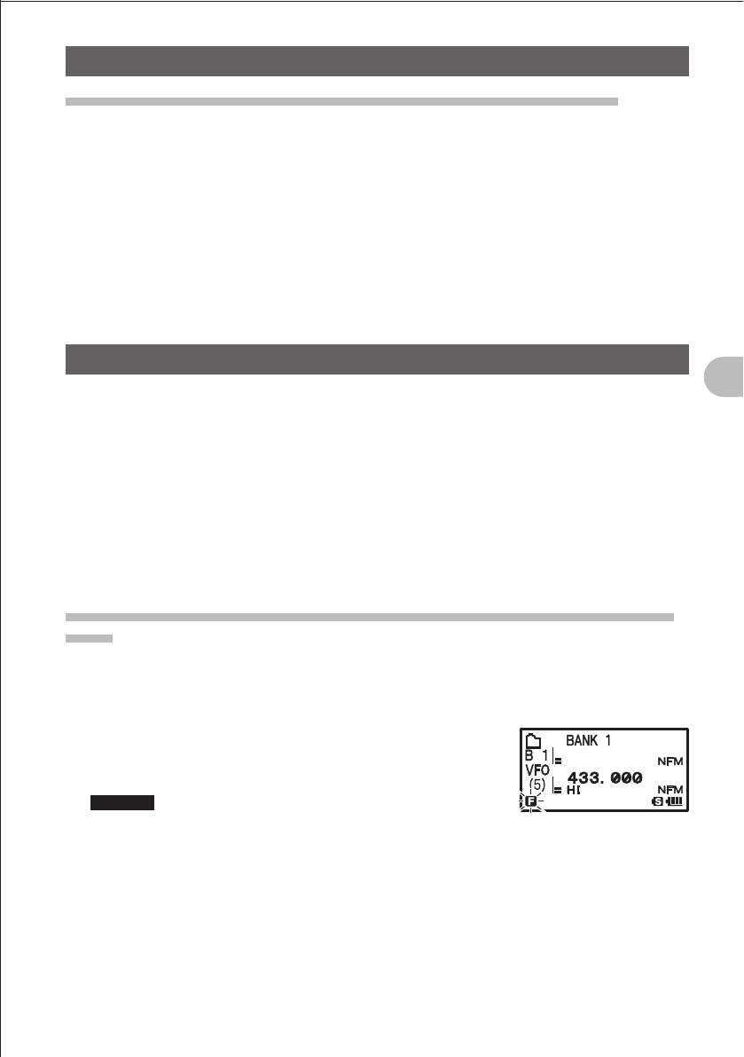
45
Using the Memory
Using Memory Banks
Canceling Memory Channel Registration in a Memory Bank
1 Recall the memory bank subject to cancellation of memory channel registration.
By referring to “Recalling a Memory Bank”, recall the memory bank in which the
memory channel subject to cancellation is registered.
2 Turn the O knob to select a memory channel.
Select a memory channel subject to cancellation.
3 Press the F key more than 1 second, and then press the D key.
Registration of memory channel in the memory bank is cancelled, returning to the
memory bank display state. If no other memory channel is registered in the memory
bank, the memory bank having the lowest bank number is displayed.
Convenient Special Banks
Frequencies of international VHF (marine) radios (57 channels), are preset in the
special bank memories, and these channels can be selected in advance from region to
region.
• International VHF (marine) radio preset memory “SP2 International
VHF” ...................................................................................................................Page 51
Frequencies (57 channels) used for international VHF (marine) radios are assigned to
the dedicated special bank.
• World broadcast preset memory “SP5 Shortwave Broadcasts” ..................Page 00
You can listen to major broadcasts around the world (total 89 channels).
Registering Your Favorite Special Memory Channels in a Memory
Bank
You can register your favorite special memory channel in a memory bank.
1 Turn the O knob to select a special memory channel.
Select your favorite special memory channel.
2 Press the F key more than 1 second.
The Memory Bank Write mode is selected.
The f icon blinks on the display.
Remarks To cancel registration, press the p key.
3 Turn the O knob to select a memory bank number.
Select the memory bank in which you want to register your favorite special memory
channel.
4 Press the F key briefly.
The special memory channel is registered in the memory bank, and the frequency is
displayed on the LCD.
FCC ID: K6620445X20
IC: 511B-20445X20
YAESU MUSEN CO., LTD.
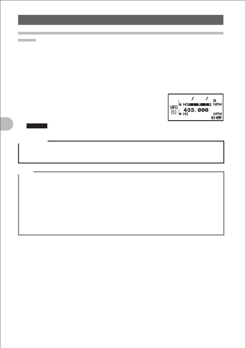
46
Using the Memory
Convenient Special Banks
Recalling a Special Bank to Listen to the International VHF (Marine)
Radio
The frequencies (57 channel) used for the international VHF (marine) radio are
registered in the dedicated special bank.
1 Press the A key.
Set the A-band to the operating band.
2 Press the F key briefly, and then press the 3 key.
The Special Bank mode is selected.
3 Press the B key.
Select “INTERNATIONAL VHF”.
4 Turn the O knob to select a channel.
Select the channel of your favorite international VHF.
Remarks To cancel reception of the international VHF, press the 3 key.
Precaution
Article 59 of the Radio Law stipulates that radio communication with a specific remote party shall not
be intercepted, and its existence or contents shall not be leaked or used surreptitiously.
By law, leak or surreptitious use of other people’s conversation is prohibited.
Hints
• The special bank cannot be rewritten with the data of another frequency.
• To scan special bank channels toward higher channel numbers, press the B key more than
1 second, and then release it. Turning the O knob one click counterclockwise will scan channels
toward lower channel numbers. If a signal is received during scanning, the current frequency is held
for 5 seconds with scanning suspended.
• The operation to perform when scanning stops can be set following the procedure described in the
“Reception Method When Scanning Stops” on page 57.
• You can register your favorite international VHF (marine) radio in a memory bank following the
procedure described in “Registering Your Favorite Special Memory Channels in a Memory Bank” on
page 48.
䠩䠮䠩䠮
䠍䠒䠌䠊䠒䠑䠌
䠍䠒䠌䠊䠒䠑䠌
䠩䠮
䠩䠮
䠍
FCC ID: K6620445X20
IC: 511B-20445X20
YAESU MUSEN CO., LTD.
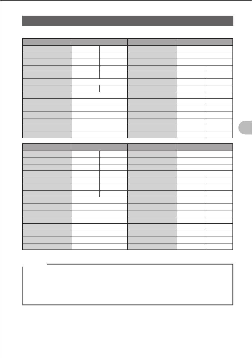
47
Using the Memory
Convenient Special BanksConvenient Special Banks
Frequencies of International VHF (Marine) radios Registered in Special Bank
Channel No. Frequency (MHz) Channel No. Frequency (MHz)
1 156.050 160.650* 15 156.750
2 156.100 160.700* 16 156.800
3 156.150 160.750* 17 156.850
4 156.200 160.800* 18 156.900 161.500*
5 156.250 160.850* 19 156.950 161.550*
6 156.300 20 157.000 161.600*
7 156.350 160.950* 21 157.050 161.650*
8 156.400 22 157.100 161.700*
9 156.450 23 157.150 161.750*
10 156.500 24 157.200 161.800*
11 156.550 25 157.250 161.850*
12 156.600 26 157.300 161.900*
13 156.650 27 157.350 161.950*
14 156.700 28 157.400 162.000*
Channel No. Frequency (MHz) Channel No. Frequency (MHz)
60 156.025 160.625* 74 156.725
61 156.075 160.675* 75 156.775
62 156.125 160.725* 76 156.825
63 156.175 160.775* 77 156.875
64 156.225 160.825* 78 156.955 161.550*
65 156.275 160.875* 79 156.975 161.575*
66 156.325 160.925* 80 157.025 161.625*
67 156.375 81 157.075 161.675*
68 156.425 82 157.125 161.725*
69 156.475 83 157.175 161.775*
70 156.525 84 157.225 161.825*
71 156.575 85 157.275 161.875*
72 156.625 86 157.325 161.925*
73 156.675 87 157.375 161.975*
88 157.425 162.025*
Remarks
* is the frequency of the base station. For example, if channel 1 is selected, the base station
frequency 160.650 MHz and the @ icon are displayed. Pressing the F key briefly and then
pressing the 5 key briefly displays the Ship Station frequency 160.650 MHz is displayed and the @
icon blinks. The base station frequency minus 4.6 MHz equals the Ship Station frequency, and duplex
operation starts. To return to the base station frequency, press the F key briefly, and then press the
5 key briefly.
FCC ID: K6620445X20
IC: 511B-20445X20
YAESU MUSEN CO., LTD.
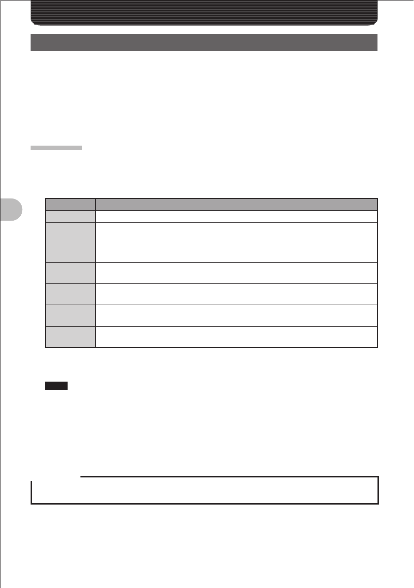
48
Scanning Function
Scanning Function
Using the Scanning Function
The FT-1DR supports the following four scan modes:
(1) VFO Scan
(2) Memory Scan
(3) Programmable Memory Scan
(4) Selected Memory Channel Scan
VFO Scan
1 Select the VFO mode, and then select a band to scan.
2 While pressing the B key, turn the O knob to specify the scanning range.
Specify the scanning range as follows.
Display* Operation
ALL Scans all bands within the range from the current frequency to 108-999 MHz.
(PMS
number)
Shortcuts the PMS scanning procedure (steps 1 and 2 described on page 46).
If PMS memories have been registered in advance, PMS memory numbers are
displayed. Turn the O knob to select the PMS memory you want to scan, and then
scan the PMS range.
± 1 MHz Scans the current band (see the table on the next page) within ± 1 MHz of the
current frequency.
± 2 MHz Scans the current band (see the table on the next page) within ± 2 MHz of the
current frequency.
± 5 MHz Scans the current band (see the table on the next page) within ± 5 MHz of the
current frequency.
BAND Scans the current band (see the table on the next page) starting with the current
frequency.
3 Release the B key.
Scanning (SCAN) starts toward higher frequencies.
Hints While the B key is pressed down, the scanning range is displayed on the LCD.
When a signal is received during scanning, the decimal point blinks.
Turn the O knob clockwise.: Scanning is performed toward higher frequencies.
Turn the O knob counterclockwise.: Scanning is performed toward lower frequencies.
When a signal is received during scanning, a beep is emitted and its frequency is displayed
for 5 seconds. When scanning is suspended, the decimal point blinks and the LCD stays lit.
After receiving the signal for 5 seconds, scanning resumes.
Precaution
The difference between the upper limit frequency and the lower limit frequency for PMS must be 100
kHz or more.
FCC ID: K6620445X20
IC: 511B-20445X20
YAESU MUSEN CO., LTD.
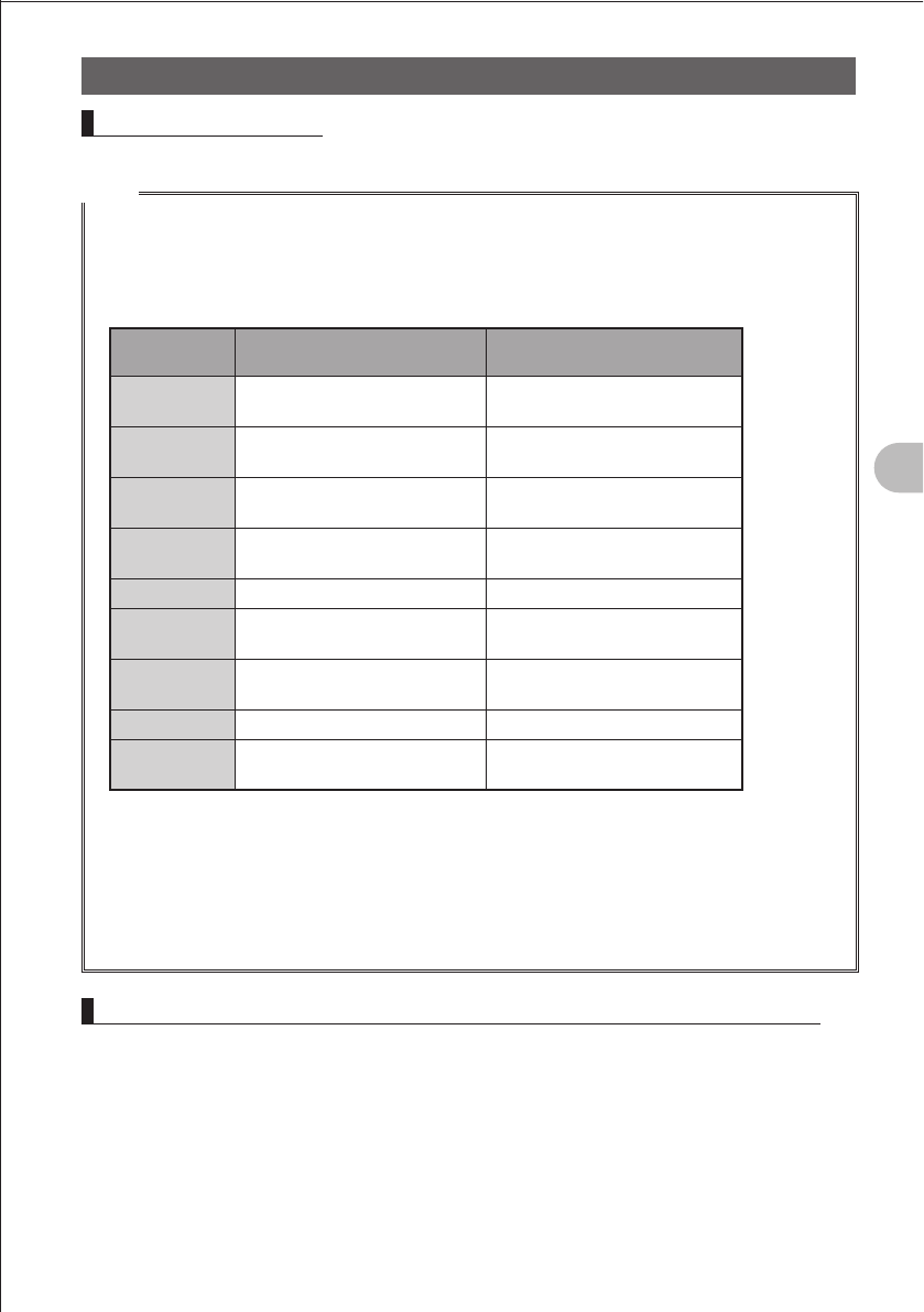
49
Scanning Function
Using the Scanning Function
Canceling Scanning
To cancel scanning, press the p switch.
Hints
• Even during scanning, you can adjust the squelch in the following procedure:
Press the F key briefly. Press the T key. Turn the O knob to adjust the squelch.
• During scanning, you can finish the squelch adjustment in the following procedure:
Press the F key briefly. Press the T key.
A-band and B-band reception frequencies
Frequency
band No. A-BAND B-band
(1) 1.8 MHz to 30 MHz
(Shortwave band)
(2) 30 MHz to 76 MHz
(50 MHz band )
(3) 108 MHz to 137 MHz
(Aviation radio band)
108 MHz to 137 MHz
(Aviation radio band)
(4) 137 MHz to 174 MHz
(144 MHz band)
137 MHz to 174 MHz
(144 MHz band)
(5) 174 MHz to 222 MHz 174 MHz to 222 MHz
(6) 222 MHz to 420 MHz
(Information radio band (1))
222 MHz to 420 MHz
(Information radio band (1))
(7) 420 MHz to 470 MHz
(430 MHz band)
420 MHz to 470 MHz
(430 MHz band)
(8) 470 MHz to 770 MHz 470 MHz to 770 MHz
(9) 770 MHz to 999 MHz
(Information radio band (2))
• For the operation to perform when scanning stops, see “Selecting a Reception Method When
Scanning Stops” on page 57.
• Press the M key more than 1 second to select the Set mode, and then select the following items
for more convenient use:
“7 CONFIG” “3 BEEP” “EDGE”: Emits a beep when the frequency band edge is reached.
“7 CONFIG” “3 BEEP” “SELECT”: Prevents a beep from being emitted when scanning stops.
“5 SCAN” “2 SCAN LAMP”: Prevents the LCD from being lit when scanning stops.
Skipping a Frequency You Do Not Want Scan (Skip Search Memory)
Scanning may stop at a frequency that you do not want to receive. Such a frequency
can be skipped by storing it in the “skip search memory”. Up to 99 frequencies can be
saved in the skip search memory (memory channels 901 to 999).
FCC ID: K6620445X20
IC: 511B-20445X20
YAESU MUSEN CO., LTD.

50
Scanning Function
Using the Scanning Function
Specifying the Frequency You Do Not Want to Scan
1 Start VOF scanning.
Start VOF scanning with reference to “VFO Scanning” on page 63.
2 When scanning stops at the frequency you do not want to receive, press the F key
more than 1 second.
Numbers of unprogrammed skip search memory channels blink.
Hints Turning the O knob allows you to specify other skip search memory channels.
3 Press the F key briefly.
The frequency is saved in the skip search memory, and scanning resumes.
Hints • You can specify the frequency you do not want to receive by using the following procedure in
advance:
1 In the VFO mode, tune in to the frequency you do not want to scan.
2 Press the F key more than 1 second.
3 Turn the O knob to select a skip search memory channel.
4 Press the F key briefly.
• To cancel scanning, press the p key.
Deleting a Frequency Saved in the Skip Search Memory
The frequency saved in the skip search memory can be deleted in the following
procedure. After this, the deleted frequency is scanned.
1 Select the Memory mode.
2 Press the F key more than 1 second.
3 Turn the O knob to select a memory channel of the skip search memory.
Select the memory channel (901-999) containing the frequency you want to delete.
When selecting a memory channel, pressing the M key allows you to skip memory
channel numbers in steps of 100 memory channel numbers.
4 Press the D key.
“DELETE OK?” is displayed on the LCD.
5 Press the X key.
The saved frequency is deleted.
Hints To delete another frequency from the skip search memory, repeat steps 2-4.
Hint
• Restoring the Frequency Deleted from the Skip Search Memory
If you have not specified a new frequency for the same memory channel, you can restore the
deleted frequency by repeating steps 1-4.
FCC ID: K6620445X20
IC: 511B-20445X20
YAESU MUSEN CO., LTD.
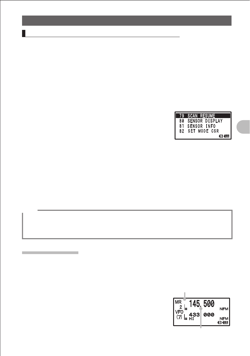
51
Scanning Function
Using the Scanning Function
Selecting a Reception Method When Scanning Stops
When scanning stops, you can select one of the following three reception methods:
(1) The signal is received for the specified period of time, and then scanning resumes.
You can specify this period of time in steps of 0.5 second within the range from 2
seconds to 10 seconds.
(2) The signal is received until it fades out. Two seconds after the signal fades out,
scanning resumes. “BUSY” is displayed on the LCD.
(3) Scanning stops and the current frequency is received. “HOLD” is displayed on the
LCD.
1 Press the M key more than 1 second.
2 Turn the O knob to select “5 SCAN”.
3 Press the M key briefly.
4 Turn the O knob to select “4 SCAN RESUME”.
5 Press the M key briefly.
6 Turn the O knob to select a reception method.
Select a reception method from “2 SEC TO 10 SEC (0.5 SEC STEP)”, “BUSY”, and
“HOLD”.
7 Press the M key more than 1 second.
The selected reception method is determined.
8 Press the M key more than 1 second again.
The Set mode is canceled.
Hints
• The reception method selected here is also applied to “VFO Scanning”, “Programmable Memory
Scanning”, and “Dual Reception”.
• The “BUSY” scanning start time can be changed by selecting the Set mode item “3 SCAN
RE-START”.
Memory Scanning
Frequencies saved in the memory can be scanned in the order of memory channel
number.
1 Select the Memory mode, and recall memory channel.
2 While pressing the B key, turn the O knob to specify
the scanning range.
Specify the scanning range with reference to the table on
the next page.
While the B key is
pressed down, the scanning
range is displayed.
When a signal is received,
the decimal point blinks.
FCC ID: K6620445X20
IC: 511B-20445X20
YAESU MUSEN CO., LTD.
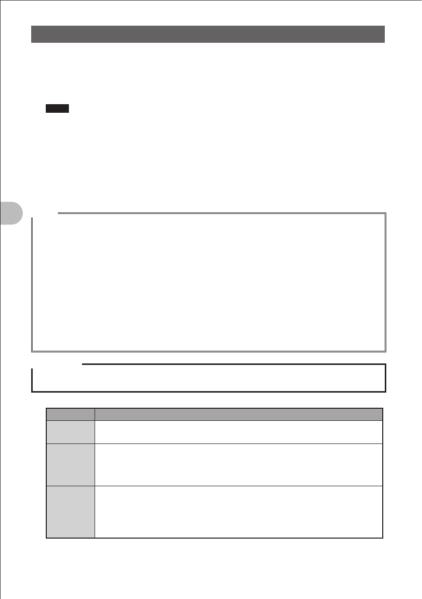
52
Scanning Function
Using the Scanning Function
3 Release the B key.
Scanning (SCAN) is performed toward higher memory channel numbers.
While the B key is pressed down, the scanning rage is displayed on the LCD.
When a signal is received, the decimal point blinks.
Hints • Turn the O knob clockwise.:
Scanning is performed toward higher memory channel numbers.
Turn the O knob counterclockwise.:
Scanning is performed toward lower memory channel numbers.
• When a signal is received during scanning, scanning stops for 5 seconds and this frequency
is received.
• When scanning is suspended, the decimal point blinks and the LCD stays lit.
• After receiving the frequency for 5 seconds, scanning resumes.
• To cancel scanning, press the p switch.
Hints
• Even during scanning, you can adjust the squelch in the following procedure:
Press the F key briefly. Press the T key. Turn the O knob to adjust the squelch.
• During scanning, you can finish the squelch adjustment in the following procedure:
Press the F key briefly. Press the T key.
• When memory channels are recalled, they are regular memory channels (memory numbers 1-900).
• When a memory bank is recalled, only the memory channels in the memory bank are scanned.
• For the operation to perform when scanning stops, see “Selecting a Reception Method When
Scanning Stops” on page 57.
• Press the M key more than 1 second to select the Set mode, and then select the following items
for more convenient use:
“7 CONFIG” “3 BEEP” “EDGE”: Emits a beep when the frequency band edge is reached.
“7 CONFIG” “3 BEEP” “SELECT”: Prevents a beep from being emitted when scanning stops.
“5 SCAN” “2 SCAN LAMP”: Prevents the LCD from being lit when scanning stops.
Precaution
The difference between the upper limit frequency and the lower limit frequency for PMS must be 100
kHz or more.
Display Operation
ALL CH Scans all memory channels (1-900) of the currently selected memory. When
selected memory channels are specified, all of them are scanned (See page 59).
(PMS No.)
Shortcuts the PMS scanning procedure (steps 1 and 2 described on page 62).
When a PMS memory has been registered in advance, its number is displayed. Turn
the O knob to select the PMS memory you want to scan, and then scan the range
between the upper and lower limits of the PMS.
BAND
Scans only the memory channels for which frequencies in the same frequency
band*1 as that of the currently selected memory are saved.
When selected memory channels are specified, scans only the selected memory
channels for which frequencies in the same frequency band*1 as that of the currently
selected memory are saved (See page 59).
*1 For the relationship between frequency bands and reception frequencies, see the table at the
bottom of page 56.
FCC ID: K6620445X20
IC: 511B-20445X20
YAESU MUSEN CO., LTD.
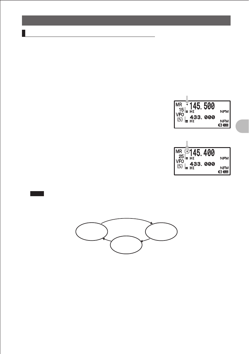
53
Scanning Function
Using the Scanning Function
Specifying a Skip/Selected Memory Channel
You can specify two types of memory channels, a skip memory channel and a selected
memory channel, for effective memory scanning.
Skip memory channel: You can specify a memory channel that need not be scanned
during memory scanning.
Selected memory channel: You can specify selected memory channels so that only
the specific memory channels are scanned during memory
scanning.
1 Select the Memory mode, and then recall the memory
channel you want to specify as a skip memory channel or
a selected memory channel.
2 Press the M key more than 1 second.
The Set mode is selected.
3 Turn the O knob to select “3 MEMORY”.
4 Press the M key briefly.
5 Turn the O knob to select “5 MEMORY SKIP”.
6 Press the M key briefly.
7 Turn the O knob to select “OFF”, “SKIP”, or “SELECT”.
8 Press the M key more than 1 second.
9 Press the M key more than 1 second again.
The Set mode is canceled.
Hints To cancel a skip/selected memory channel, select [OFF].
When it is canceled, the icon on the LCD disappears.
Skip memory
channel
[SKP]
Selected memory
channel
[SELECT]
O
[OFF]
Stays lit for the skip memory.
Blinks for the selected
memory channel.
FCC ID: K6620445X20
IC: 511B-20445X20
YAESU MUSEN CO., LTD.

54
Scanning Function
Using the Scanning Function
Scanning Only the Selected Memory Channel
1 Select the Memory mode, and then recall the selected
memory channel.
2 While pressing the B key, turn the O knob to specify
the scanning range.
Hints For the scanning range to be specified, see the table on page
66.
3 Release the B key.
Hints • Scanning (SCAN) is performed toward higher memory channel numbers.
• Only the selected memory channel is scanned.
• If a signal is received during scanning, a beep is emitted and scanning stops for 5 seconds
to receive the current frequency.
• While scanning is suspended, the decimal point blinks and the display stays lit.
• After receiving the frequency for 5 seconds, scanning resumes.
• To cancel scanning, press the p key briefly.
Scanning a Memory Bank
Only the memory channels in the recalled memory bank can be scanned.
1 Press the V key.
The Memory mode is selected.
2 Press the B key briefly.
Recall a memory bank.
Pressing the B key briefly toggles between “MEMORY NO.” and “BANK (No.)”.
Hints To recall another memory bank, press the F key briefly, and the press the B key briefly.
3 Turn the O knob to select a memory bank.
Select a memory bank from among BANK 1 to BANK 24.
4 Press the B key briefly.
The selected memory bank is determined.
5 While pressing the B key, turn the O knob to specify the scanning range.
Hints For the scanning range to be specified, see the table on page 66.
6 Release the B key.
Scanning (SCAN) is performed toward higher memory channel numbers.
Hints • Turn the O knob clockwise.:
Scanning is performed toward higher memory channel numbers.
Turn the O knob counterclockwise.:
Scanning is performed toward lower memory channel numbers.
• When a signal is received during scanning, scanning stops for 5 seconds and this frequency
is received.
• When scanning is suspended, the decimal point blinks and the LCD stays lit.
• After receiving the frequency for 5 seconds, scanning resumes.
• To cancel scanning, press the p switch.
FCC ID: K6620445X20
IC: 511B-20445X20
YAESU MUSEN CO., LTD.
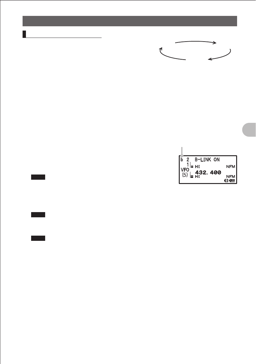
55
Scanning Function
Using the Scanning Function
Memory Bank Link Scan
During regular memory bank scanning, only the
memory channels assigned to the recalled memory
bank are scanned. During memory bank link
scanning, memory channels registered in two or more
previously specified banks can be scanned.
1 Press the V key.
The Memory mode is selected.
2 Press the B key briefly.
Recall a memory bank.
3 Press the F key briefly, and then press the B key briefly.
4 Turn the O knob to select a memory bank.
Select a memory bank subject to bank link scanning.
5 Press the V key briefly.
Select the bank link.
The memory bank number changes from “B” to “b”,
indicating that the bank link has been activated
6 Repeat steps 2-4 to select another memory bank.
Hints For the scanning range to be specified, see the table on page
66.
7 Press the B key briefly.
The memory banks subject to memory bank scanning are determined.
8 While pressing the B key, specify a scanning range.
Hints For the scanning range to be specified, see the table on page 66.
9 Release the B key.
Scanning (SCAN) is performed toward higher memory channel numbers.
Hints • Turn the O knob clockwise.:
Scanning is performed toward higher memory channel numbers.
Turn the O knob counterclockwise.:
Scanning is performed toward lower memory channel numbers.
• When a signal is received during scanning, scanning stops for 5 seconds and this frequency
is received.
• When scanning is suspended, the decimal point blinks and the LCD stays lit.
• After receiving the frequency for 5 seconds, scanning resumes.
• To cancel scanning, press the p switch.
OCanceling Bank Link Scanning
1 Press the F key briefly, and then press the B key briefly.
2 Recall the link for which bank link scanning was specified.
3 Press the V key briefly.
The memory bank number changes from “b” to “B”, indicating that the bank link has
been deactivated.
BANK 1 BANK 10
BANK 24
The memory bank number
change from “B” to “b”.
FCC ID: K6620445X20
IC: 511B-20445X20
YAESU MUSEN CO., LTD.
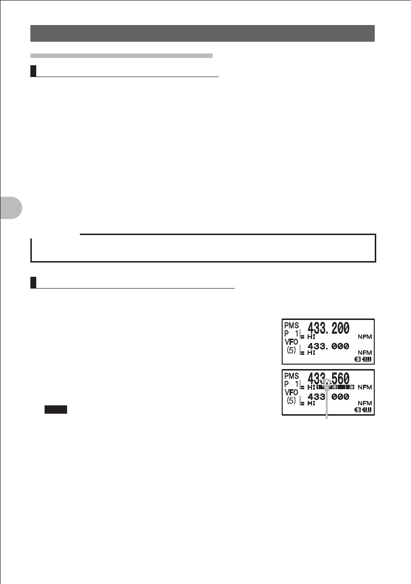
56
Scanning Function
Using the Scanning Function
Programmable Memory Scan (PMS)
Writing into a Programmable Memory
50 sets of PMS memory channels (L1/U1 to L50/U50) are available.
Specify the lower limit frequency of the frequency range you want to san for “L¼”, and
the upper limit frequency for “U¼”.
Enter a number between 1 and 50 for “¼”. Use the same number for the lower and
upper limit channels.
Specify the lower limit frequency and upper limit frequency for the PMS memory
channels according to page 39.
PMS memory channels are located late in the memory channel area. When there are
100 or more memory channels, press the M key to skip memory channels quickly in
steps of 100 memory channels.
Example: Specification of the lower limit frequency “433.200 MHz” and the upper limit
frequency “433.700 MHz” for PMS
Precaution
The difference between the upper limit frequency and the lower limit frequency for PMS must be 100
kHz or more.
Performing Programmable Memory Scan
The programmable memory allows you to scan the specified frequency range in the
same frequency band.
1 Select the Memory mode.
Recall the PMS memory storing the lower limit frequency
or upper limit frequency.
2 Press the B key, and then turn the O knob to select
a PMS channel.
3 Release the B key.
Programmable memory scanning starts.
Hints • Turn the O knob clockwise.:
Scanning is performed toward higher memory channel
numbers.
Turn the O knob counterclockwise.:
Scanning is performed toward lower memory channel numbers.
• When a signal is received during scanning, scanning stops for 5 seconds and this frequency
is received.
• When scanning is suspended, the decimal point blinks and the LCD stays lit.
• After receiving the frequency for 5 seconds, scanning resumes.
To select another PMS memory , press the B knob to select it while pressing the O.
• To cancel scanning, press the p switch.
The decimal point blinks.
FCC ID: K6620445X20
IC: 511B-20445X20
YAESU MUSEN CO., LTD.

57
Scanning Function
Using the Scanning Function
Hints
• If PMS memory channels have already been assigned to L1/U1 to L50/U50, selecting a PMS
number in the VFO scanning procedure described on page 56 allows you to skip step 1 described
above.
• When a skip memory (P¼¼) is specified for “L¼” or “U¼” or when the lower/upper limit frequency is
not properly specified, program memory scanning is not performed properly.
• Press the M key more than 1 second to select the Set mode, and then select the following items
for more convenient use:
“7 CONFIG” “3 BEEP” “EDGE”: Emits a beep when the frequency band edge is reached.
“5 SCAN” “2 SCAN LAMP”: Prevents the LCD from being lit when scanning stops.
• Even during scanning, you can adjust the squelch in the following procedure:
Press the F key briefly. Press the T key. Turn the O knob to adjust the squelch.
• During scanning, you can finish the squelch adjustment in the following procedure:
Press the F key briefly. Press the T key.
Using the Search Function
Spectrum Scope Searching for a Signal Using a Signal Strength Graph
During mono band reception in the VFO mode, strengths of channel signals around the
current frequency can be graphically displayed on the LCD.
1 Press the F key briefly, and then press the 2 key.
Use states of 16 channels (eight channels above the current frequency and eight
channels below the current frequency) are checked and the corresponding signal
strengths are displayed graphically on the LCD.
2 Turn the O knob to move the icon to the signal position.
The signal at the center frequency can be received.
Hints To resume scanning, press the V key.
3 Press the F key briefly, and then press the 2 key.
The spectrum scope is deactivated.
Hints
• Normally, the spectrum scope can check 16 channels around the current frequency. Pressing the
A key allows you to select the channel check range from among ± 5, ± 9, ± 16, ± 24, and ± 50.
• When ± 5 is selected, numeric values representing signal strengths are displayed in the graph.
• The spectrum scope channel interval is the same as the VFO frequency step.
• When the spectrum scope is running, numeric, %, X, and D keys cannot be used.
• By default, channel use states are displayed graphically after completion of scanning, and the
sound of the signal at the center frequency is output if such signal is detected. Turning the O knob
allows you to restart scanning.
• Selecting “1 DISPLAY” “2 BAND SCOPE” “CONTINUOUS” in the Set mode allows you to view
the latest use states through repetitive scanning.
To stop scanning, press the V key.
To stop spectrum analysis, press the F key, and then press the 2 key.
• Selecting “1 DISPLAY” “2 BAND SCOPE” “FULL TIME” in the Set mode allows sound to be
emitted with the spectrum scope running.
However, sound cannot be emitted in frequency bands 580 MHz to 999 MHz.
FCC ID: K6620445X20
IC: 511B-20445X20
YAESU MUSEN CO., LTD.
58
Using the GPS Function
Using the GPS FunctionUsing the GPS Function
What is GPS?
GPS (Global Positioning System) is a space-based satellite navigation system that
provides location and time information anywhere on the earth. It was developed by the
U.S. Department of Defense as a military system. It receives signals from three or more
of about 30 GPS satellites flying at an altitude of about 20,000 km, and displays the
current position (latitude, longitude, and altitude) within a tolerance of several meters. In
addition, GPS can receive the exact time from the satellite’s onboard atomic clock.
Activating the GPS Function
To activate the GPS function, select “8 APROS” “23GPS POWER”, and then select
“GPS ON” in the Set mode.
Hint
• Default: ON
When the GPS function of the FT1DR is turned ON, internal clock settings and position
settings for your station are automatically obtained from the GPS data.
Precaution
zData for the current day of the week is not automatically obtained. Set the day of the week manually
with reference to page .
1 Press the M key over 1 second.
The Set mode is selected.
2 Turn the O knob to select “8 APRS”.
3 Press the M key briefly.
4 Turn the O knob to select “16 GPS POWER”.
5 Press the M key briefly.
6 Turn the O knob to select “GPS ON”.
7 Press the M key for more than 1 second.
The GPS function is turned ON.
8 Press the M key for more than 1 second again.
The Set mode is canceled.
FCC ID: K6620445X20
IC: 511B-20445X20
YAESU MUSEN CO., LTD.
59
Using the GPS Function
Activating the GPS Function
Hints
• Information about the current positions of radio stations provided by GPS can be saved in 10
memories (P1 to P10). Saved position information can be used to set the position of your station
(See page 111).
• When the GPS function is active, power consumption increases about 40 mA. As a result, the
battery life is reduced by about 20% compared to when the GPS function is deactivated.
• To use the GPS function during APRS operation, be sure to select “8 APRS” “27 MY POSITION”,
and then select “GPS” in the Set mode.
Method of Positioning by GPS
1 Turn on the FT1DR.
2 Shortly press the M key twice.
The GPS screen appears.
Pressing the M key switches among FT1DR screens in the following order:
Usual frequency display BACK TRACK display GPS display ARTS-D
display WiRES-X display
Precaution The ARTS-D screen and the WiRES-X screen are displayed when the corresponding
functions are active.
Since the FT1DR searches satellites, it requires a few minutes to display the
positioning result.
3 GPS data is displayed.
An arrow icon (the direction in which you are heading),
your current position, number of satellites, longitude,
latitude, and altitude are displayed on the screen.
Hints • The arrow icon (the direction in which you are heading) will
not appear and the latitude/altitude blinks until GPS satellite data is acquired.
•
When GPS satellite data has been acquired, the arrow icon (the direction in which you are
heading) will appear, the latitude/altitude will change from blinking to lit, and your current
position will be displayed.
• If acquisition of GPS satellite data is interrupted due to an obstacle, such as a building or
tunnel, only the arrow icon (the direction in which you are heading) disappears.
4 Press the A key to scroll the screen.
Pressing the A key scrolls the screen and displays the
current time.
Pressing the A key again displays GPS data.
FCC ID: K6620445X20
IC: 511B-20445X20
YAESU MUSEN CO., LTD.

60
Using the GPS Function
Method of Positioning by GPS
About Positioning by GPS
“Positioning” refers to calculation of your current position from the satellite orbit
information and radio propagation time. At least three satellites need to be captured
for successful positioning. If positioning fails, move away from buildings as far as
possible and stand in an area with open sky.
About errors
A positioning error by several hundred meters can occur due to the environmental
conditions. Under favorable conditions, positioning can be performed successfully
using only three satellites. However, under the following poor conditions, the
positioning accuracy can decrease or positioning can fail.
- Between high-rise buildings
- On a narrow road between buildings
- In a room or behind a building
- Under high-voltage cable or overpass
- Between trees such as in the woods
- In a tunnel or underground
- Usage behind heat reflective glass
- Places with strong magnetic fields
When using the GPS function for the first time today
When you use the GPS function for the first time after purchase of the FT1DR or
today, a few minutes are required to search for satellites. Also, when using the GPS
function after turning off the FT1DR for several hours, a few minutes are required to
search for satellites.
FCC ID: K6620445X20
IC: 511B-20445X20
YAESU MUSEN CO., LTD.
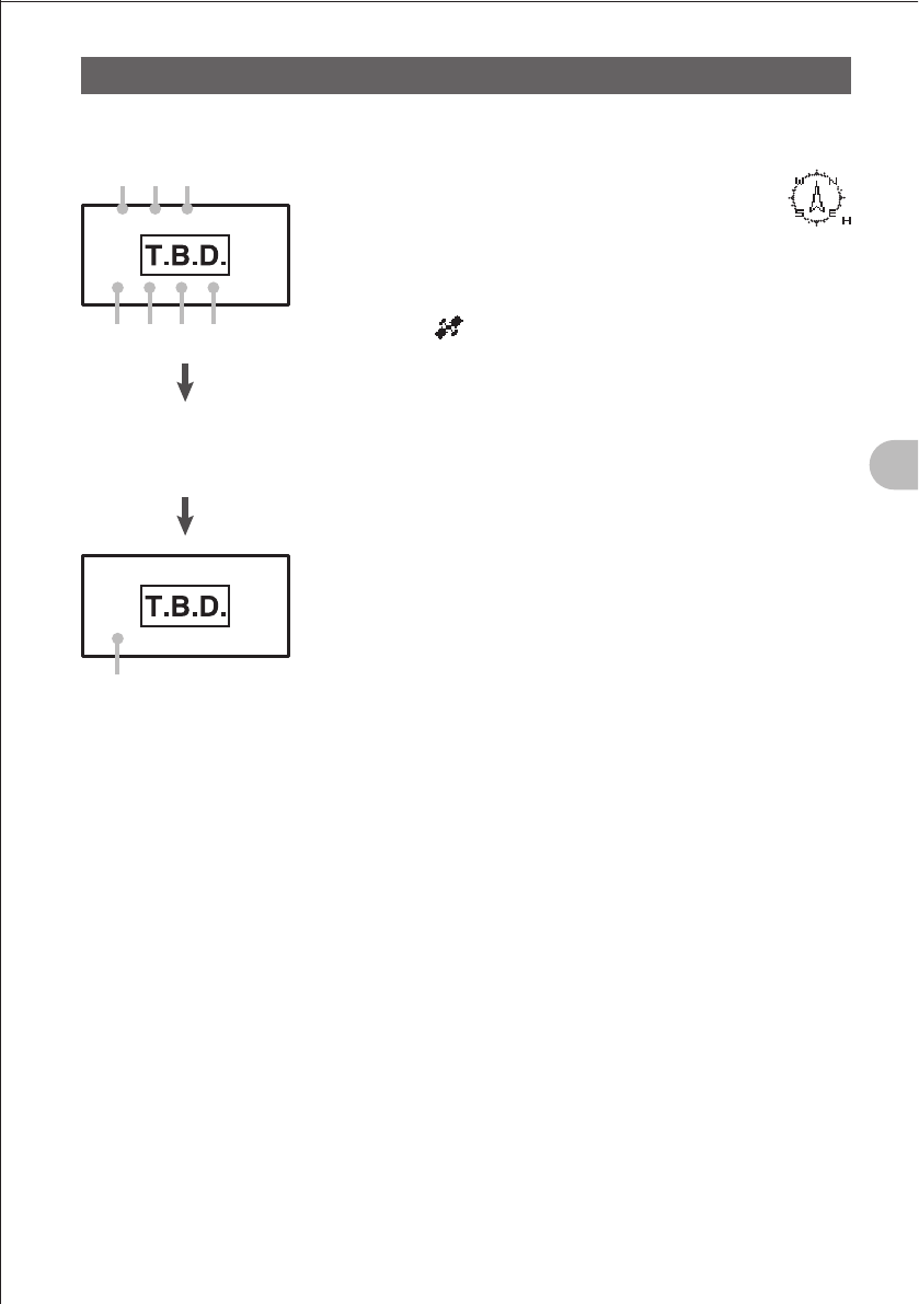
61
Using the GPS Function
Explanation of GPS Screen and OperationExplanation of GPS Screen and Operation
Activating the GPS function displays the following information on the LCD.
a
b
h
c f g
e d
Press the A key to scroll
the screen until the current
time appears.
a Compass: North-UP (North is always up.)
Heading-UP: (When B is pressed, the
direction in which you are
heading is always up. A white
arrow icon is displayed. “H” is
displayed at the lower right of the compass
icon.)
b Positioning: When at least three satellites have been captured, the
icon is displayed.
This icon is not displayed if it cannot capture at least
three icons.
c Number of satellites:
Displays the number of captured satellites.
d Latitude: The current position is displayed using north (N) or south
(S) latitude.
Display format: X DD°MM. MMM
X: X=N: North latitude, X=S: South latitude
DD: Degree
MM.MMM: Minute
Example: N 35°38.250 (35 degrees, 38 minutes, 15
seconds north latitude)
e Longitude: The current position is displayed using east (E) or west
(S) longitude.
Format: X DDD°MM. MMM
X: X=E: East longitude, X=W: West longitude
DDD: Degree
MM.MMM: Minute
Example: E 139°42.500 (139 degrees, 42 minutes, 30
seconds east latitude)
f Speed: The speed at which you are moving is displayed.
Format: SPD aaakm/h
Example: SPD 5 km/h
g Altitude: The altitude of the current position of your radio station
is displayed.
Format: ALT aaaaam
Example: ALT 20m
h Time: The current time set by GPS is displayed.
Format: aa (hour): bb (minute): cc (second)
Example: 23: 59: 59
* When an external GPS device is connected to the data
terminal, the time is displayed as follows:
aa (hour): bb (minute)
FCC ID: K6620445X20
IC: 511B-20445X20
YAESU MUSEN CO., LTD.
62
Using the GPS Function
Explanation of GPS Screen and Operation
Hints
• Selecting “8 APRS” “18 GPS UNIT” in the APRS/GPS Set mode allows you to change the unit of
GPS data.
• When the GPS function is used, the accurate time data (date and time) obtained from GPS is
displayed on a 24 hour basis. This time data is reflected in the time data displayed on the GPS
screen and APRS screen. However, data for the day of the week is not automatically obtained from
GPS. Set the day of the week manually referring to “Setting the Clock” on page .
• Selecting “8 APRS” “15 GPS DATUM” in the APRS/GPS Set mode allows you to change the
geodetic system of the built-in GPS unit. However, since APRS uses the geodetic system of WGS-
84, it is recommended not to change it.
• Selecting “8 APRS” “24 TIME ZONE” in the APRS/GPS Set mode allows you to set the time zone
by units of 30 minutes.
• When the GPS function is active, the power consumption increases by about 40 mA. As a result,
the battery life is reduced by about 20% compared to when the GPS function is deactivated.
• Selecting “8 APRS” “13 COM PORT SETTING” and then setting “INPUT” to “GPS” in the APRS/
GPS Set mode allows you to obtain position information from a external GPS device. In this case,
the data obtained from the internal GPS is disabled.
• When using an external GPS device, keep it away from the FT1DR.
BACK TRACK Function
This function allows you to return to the previously saved position (maximum of two
positions) using the GPS function.
For example, if the position where you parked your car (such as certain position in a
wide parking area of a theme park or shopping center) has been saved in the FT1DR,
you can return to your car without getting lost by following the guidance on the screen of
the FT1DR.
Causing the FT1DR to Memorize the Current Point
1 Press the M key briefly.
The BACKTRACK function screen appears.
2 Press the B key briefly.
The POINT(L1/L2) selection screen appears.
3 Turn the O knob and select “POINT L1” or “POINT L2”.
4 Press the V key.
Saves the current position.
5 Press the B key.
Returns to the BACKTRACK function screen.
FCC ID: K6620445X20
IC: 511B-20445X20
YAESU MUSEN CO., LTD.
63
Using the GPS Function
BACK TRACK Function
Using the BACK TRACK Function
1 Press the M key briefly.
The BACK TRACK function screen appears.
2 Turn the O knob and select “POINT L1” or “POINT L2”.
3 Press the B key.
Returns to the BACK TRACK function screen.
4 Press the V key.
The BACK TRACK function is activated.
The saved position (destination) appears in the direction of the
arrow within the circle.
Walk forward so that the arrow stays pointing up on the
screen.
When the distance (DST) to the saved position becomes “0.1 km”*, it will be indicated
by four beeps.
* 100 m to 200 m
When the distance (DST) to the saved position becomes “0.0 km”*, it will be indicated
by a short beep melody.
* 0 m to 100 m
When you reach the destination, the screen changes as shown
on the right, it will be indicated by a short beep, and the LED
glows white.
Description of the BACK TRACK Function Screen
POINT: Displays the saved position (L1 or L2).
DST: Displays the linear distance to the saved position.
GPS: Displays the number of captured GPS satellites.
Arrow in circle: Indicates the direction toward the saved
position.
FCC ID: K6620445X20
IC: 511B-20445X20
YAESU MUSEN CO., LTD.
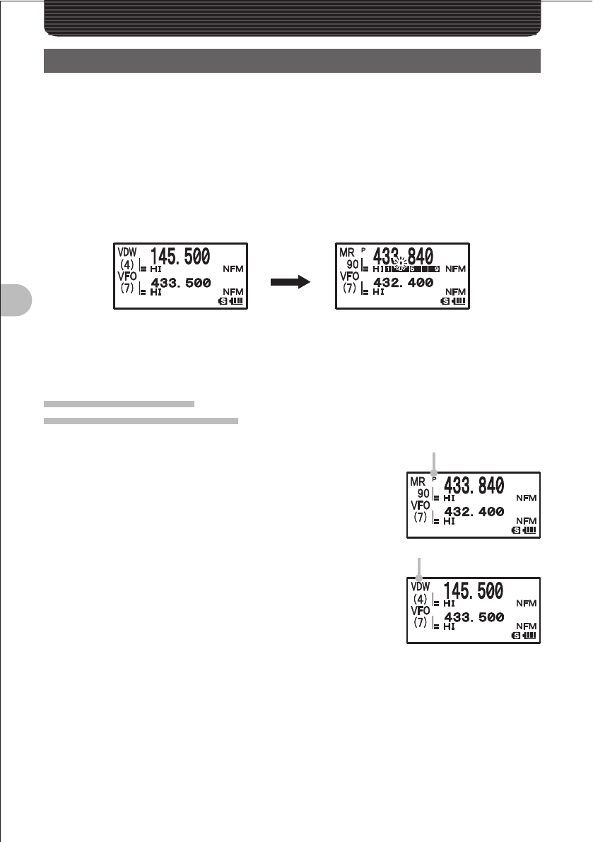
64
Useful Functions
Useful FunctionsUseful Functions
Dual Reception (DW) Functions
The FT1DR supports the following three dual reception functions:
(1) Dial dual reception
(2) Memory dual reception
(3) Home channel dual reception
The signal of the specified memory channel (priority memory channel) is checked at
intervals of about 5 seconds. If this signal is detected, it is received.
Example: Check of the signal of priority memory channel “90” during reception of
“145.500 MHz”
Frequency being received
The signal of the priority memory
channel “90” is checked at intervals of
about 5 seconds.
If the signal of the priority channel “90”
is received, the decimal point blinks.
Dial Dual Reception
VFO mode Priority memory channel
1 Select the Memory mode.
2 Press the F key more than 1 second. The Write mode is
selected, and the f icon and the channel number on the
LCD blink.
3 Turn the O knob to select a memory channel, and then
press the B key more than 1 second.
Select a memory channel (priority memory channel) whose
signal is to be received preferentially. “P” is displayed on
the LCD.
4 Select the frequency to be received.
Select the frequency to be received constantly.
5 Press the F key more than 1 second.
The Write mode is canceled.
6 Press the V key more than 1 second.
Dial dual reception starts, and “VDW ” is displayed on the LCD.
7 Press the V key briefly.
Dial dual reception is canceled.
“P” is displayed.
“VDW” is displayed.
FCC ID: K6620445X20
IC: 511B-20445X20
YAESU MUSEN CO., LTD.
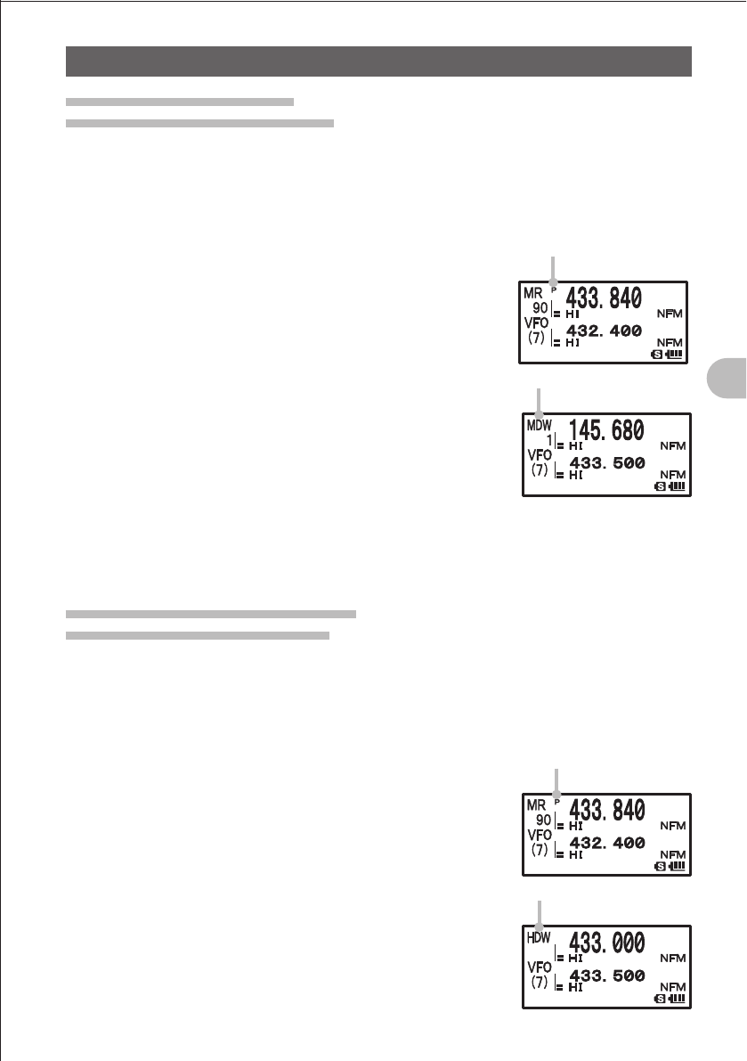
65
Useful Functions
Dual Reception (DW) Functions
Memory Dual Reception
Memory channel Priority memory channel
1 Select the Memory mode.
2 Press the F key more than 1 second.
The Write mode is selected, and the f icon and the channel number on the LCD
blink.
3 Turn the O knob to select a memory channel, and then
press the B key briefly.
Select a memory channel (priority memory channel) whose
signal is to be received preferentially. “P” is displayed on
the LCD.
4 Select the memory channel whose signal is to be received.
Select the memory channel whose signal is to be received
constantly.
5 Press the F key more than 1 second.
The Write mode is canceled.
6 Press the V key more than 1 second.
Memory dual reception starts, and “MDW ” is displayed on
the LCD.
7 Press the V key briefly.
Memory dual reception is canceled.
Home Channel Dual Reception
Home channel Priority memory channel
1 Select the Memory mode.
2 Press the F key more than 1 second.
The Write mode is selected, and the f icon and the channel number on the LCD
blink.
3 Turn the O knob to select a memory channel, and then
press the B key briefly.
Select a memory channel (priority memory channel) whose
signal is to be received preferentially. “P” is displayed on
the LCD.
4 Press the F key briefly, and then press the 4 key.
Recall the home channel.
5 Press the F key more than 1 second.
The Write mode is canceled.
“P” is displayed.
“MDW” is displayed.
“P” is displayed.
“HDW” is displayed.
FCC ID: K6620445X20
IC: 511B-20445X20
YAESU MUSEN CO., LTD.
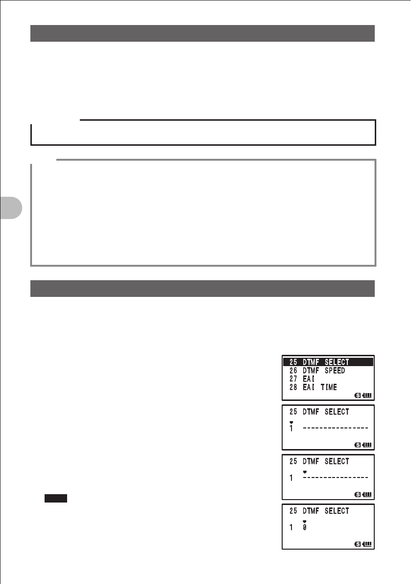
66
Useful Functions
Dual Reception (DW) Functions
6 Press the V key more than 1 second.
Home channel dual reception starts, and “HDW ” is displayed on the LCD.
7 Press the V key briefly.
Home channel dual reception is canceled.
Precaution
Be sure to assign a memory channel to the priority memory channel in advance.
Hints
• By default, memory channel 1 is assigned to the priority memory channel.
• Pressing the M key more than 1 second and changing the Set mode allows you to use this
function more conveniently.
“5 SCAN” ”1 PRI TIME”: Allows you to change the priority channel monitoring interval.
“5 SCAN””4 SCAN RESUME”: Allows you to change dual reception restart conditions.
• The constantly received frequency can be freely combined with the frequency band and mode of the
priority memory channel.
• When the signal of the priority memory channel is received, its frequency is received for 5 seconds,
and then dual reception resumes. Even during priority channel reception, pressing the p key
deactivates the dual reception function, allowing you to perform communication using that frequency.
Using the DTMF Function
“DTMF (Dual Tone Multi Frequency) tones” refer to the tones (beep boop beep) heard
from the receiver of the push-button phone. You can register the telephone number for
phone patch connection to the public telephone line, etc. with a DTMF code comprising
up to 16 characters (for up to 10 channels).
1 Press the M key more than 1 second to select the
Set mode.
2 Turn the O knob to select “4 SIGNALING”.
3 Press the M key briefly.
4 Turn the O knob to select “5 DTMF SELECT”.
5 Press the M key briefly.
6 Turn the O knob to select a channel.
Select a number (1-10) to which the DTMF code is to be
assigned.
7 Press the B key.
8 Turn the O knob to enter a DTMF code.
Hints • The DTMF code can also be entered using keypad keys.
• To correct the DTMF code, press the B (to the right) or
% (to the left) key to move the cursor to the character you
want to correct, and enter a correct character over it.
• Pressing the X key more than 1 second allows you to
delete the character at the cursor position and the subsequent
characters.
FCC ID: K6620445X20
IC: 511B-20445X20
YAESU MUSEN CO., LTD.
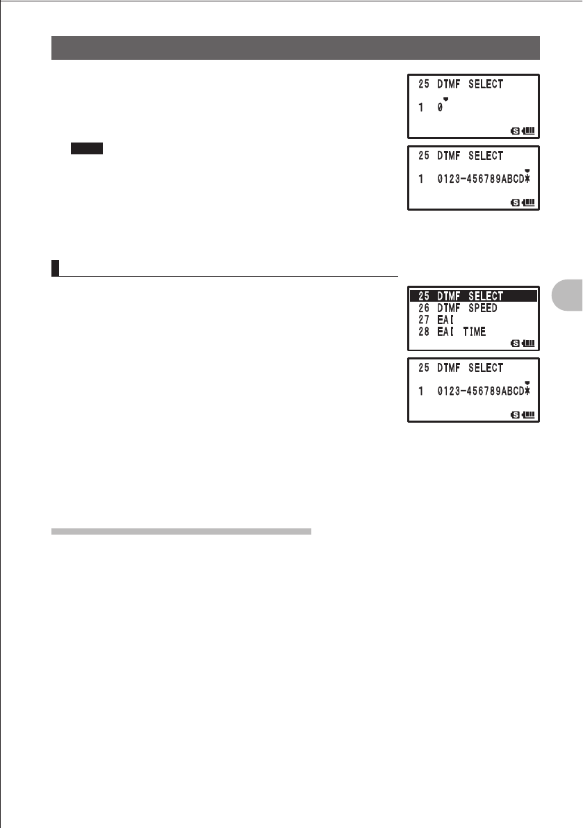
67
Useful Functions
Using the DTMF Function
9 Press the B key.
The cursor moves.
10 Repeat steps 6 and 7 to enter the remaining characters of
the DTMF code.
Hints The maximum length of the DTMF code is 16 characters.
11 Locate the cursor at the last character, and then press the
M key more than 1 second.
The DTMF code is determined.
12 Press the M key more than 1 second again.
The Set mode is canceled.
Confirming the Entered DTMF Code by the Sound
1 Press the M key more than 1 second.
The Set mode is selected.
2 Turn the O knob to select “4 SIGNALING”.
3 Press the M key briefly.
4 Turn the O knob to select “5 DTMF SELECT”.
5 Press the M key briefly.
6 Turn the O knob to select a registered channel.
7 Press the F key briefly.
You can confirm the registered DTMF code by the DTMF tones.
8 Press the M key more than 1 second.
9 Press the M key more than 1 second again.
The Set mode is canceled.
Sending the Registered DTMF Code
1 Press the M key more than 1 second.
The Set mode is selected.
2 Turn the O knob to select “4 SIGNALING”.
3 Press the M key briefly.
4 Turn the O knob to select “4 DTMF MODE”.
5 Press the M key briefly.
6 Turn the A knob to select “MODE”.
7 Turn the O knob to select “AUTO”.
8 Press the M key more than 1 second.
9 Press the M key more than 1 second again. The auto dialer is activated.
FCC ID: K6620445X20
IC: 511B-20445X20
YAESU MUSEN CO., LTD.
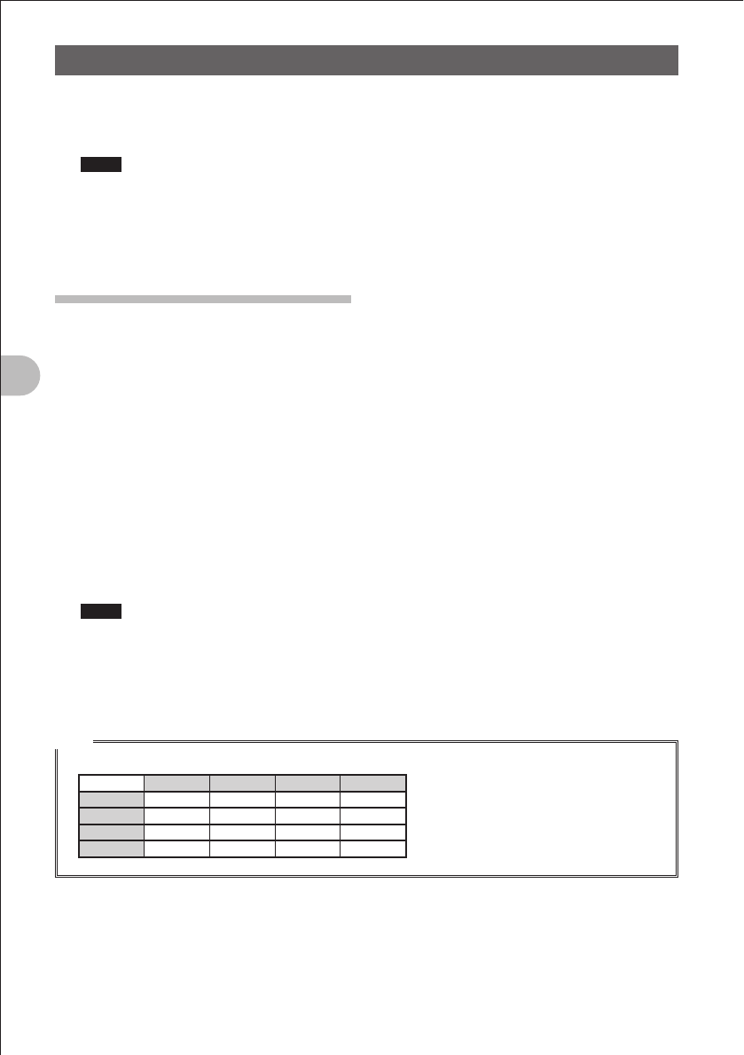
68
Useful Functions
Using the DTMF Function
10 While pressing the p switch, press your desired key (1 to 0).
Using a keypad key, select the channel of the DTMF memory containing the DTMF
code to be sent.
Hints • The registered DTMF code is sent.
• The sent DTMF tones are heard from the speaker.
11 Release the p switch.
Even after the p switch is released, sending of the DTMF signal continues until it is
completed.
Sending a DTMF Code Manually
1 Press the M key more than 1 second.
The Set mode is selected.
2 Turn the O knob to select “4 SIGNALING”.
3 Press the M key briefly.
4 Turn the O knob to select “4 DTMF MODE”.
5 Press the M key briefly.
6 Turn the O knob to select “MANUAL”.
7 Press the M key more than 1 second.
8 Press the M key more than 1 second again.
Manual entry is enabled.
9 While pressing the p switch, press one of 1 to 0 keys.
Using a keypad key, select the DTMF code to be sent.
Hints • The DTMF code corresponding to the pressed key is sent. (See the table shown below.)
• The sent DTMF tones are heard from the speaker.
10 Release the p switch.
Even after the p switch is released, sending of the DTMF signal continues until it is
completed.
Hint
• A DTMF code is a combination of two frequencies.
1209 Hz 1336 Hz 1477 Hz 1633 Hz
697 Hz 1 2 3 A
770 Hz 4 5 6 B
852 Hz 7 8 9 C
941 Hz ¼0#D
FCC ID: K6620445X20
IC: 511B-20445X20
YAESU MUSEN CO., LTD.
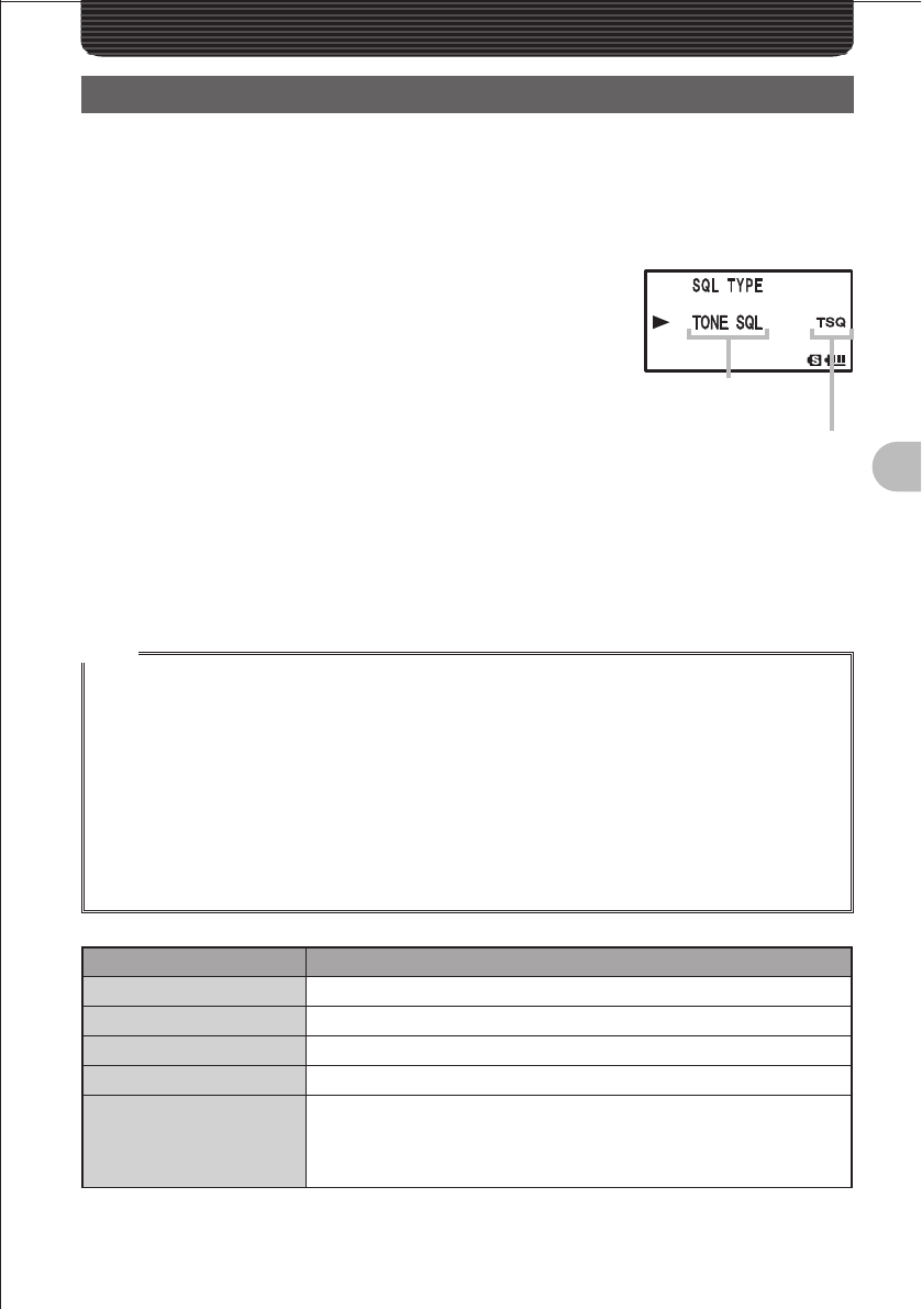
69
Communicating with a Specific Remote Station
Communicating with a Specific Remote StationCommunicating with a Specific Remote Station
Using the Tone Squelch Function
The tone squelch opens the squelch only when a signal containing the specified
frequency tone is received. Use of the digital code squelch (DCS) opens the squelch
only when a signal containing the specified DCS code is received. The tone squelch
function blocks monitoring of communications between other stations even when waiting
for call by a specific station for a long time.
1 Press the M key more than 1 second.
2 Turn the O knob to select “4 SIGNALING”.
3 Press the M key briefly.
4 Turn the O knob to select “11 SQL TYPE”.
5 Press the M key briefly.
The Set mode item “11 SQL TYPE” is selected.
6 Turn the O knob to select a squelch type.
Select a squelch type with reference to the table shown below.
7 Press the M key more than 1 second.
The selected squelch type is determined.
8 Press the M key more than 1 second again.
The Set mode is canceled.
Hints
• The tone squelch setting or the DCS setting is also effective for scanning. If scanning is performed
with the tone squelch or the DCS function turned on, it stops only when a signal containing a tone of
the specified frequency or a signal containing the specified DCS code is received.
• Pressing the Monitor switch allows you to hear signals that do not contain a tone or DCS code,
the signal that does not contain the tone of the specified frequency, and the signal which does not
contain the specified DCS code,
• Pressing the M key more than 1 second and changing the Set mode item allows you to use this
function more conveniently.
“4 SIGNALING” ”3 DCS INVERSION”: Allows you to receive the DCS code of the inverted phase.
“4 SIGNALING” ”10 SQL EXPANTION”: Allows you to specify different squelch types for
transmission and reception respectively.
Display Operation
OFF Turns off the tone sending function, tone squelch function, etc.
TONE Just sends tones (“TN” is displayed).
TONE SQ Turns on the tone squelch function (”TSQ” is displayed).
DCS Turns on the digital code squelch (“DCS” is displayed).
REV TONE
Turns on the reverse tone function (”RTN” is displayed).
Used to monitor communications based on the squelch control system in
which a tone signal is contained when communication is not performed
and the tone signal disappears when communication starts.
Squelch type is
displayed.
The logo is displayed.
FCC ID: K6620445X20
IC: 511B-20445X20
YAESU MUSEN CO., LTD.
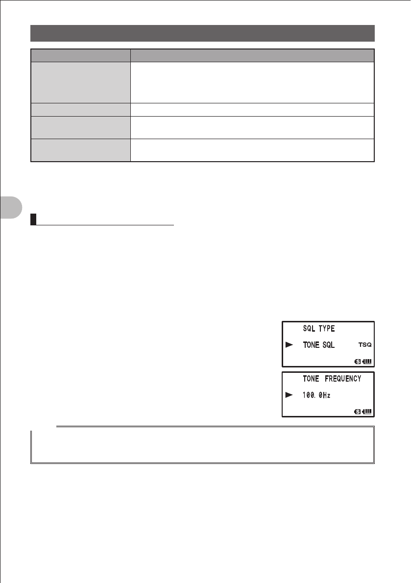
70
Communicating with a Specific Remote Station
Using the Tone Squelch Function
Display Operation
PAGER (See page 124)
Turns on a new pager function (“PAG” is displayed).
When using FT1DRs with your friends, specifying personal codes (each
code is composed of two tones) allows only a specific station to be
called.
D CD* Sends a DCS code only in case of transmission (“DC” is displayed).
TONE-DCS* Sends a tone signal in case of transmission, and waits for a DCS code in
case of reception (“T-D” is displayed).
D CD-TONE SQL* Sends a DCS code in case of transmission, and waits for a tone signal in
case of reception (“D-T” is displayed).
* Press the M key more than 1 second to select the Set mode and selecting “4 SIGNALING” “10
SQL EXPANTION” “ON” will add options “D CD”, “TONE-DCS”, and “D CD TONESQL” to the Set
mode items “4 SIGNALING” to “16 SQL TYPE”, allowing you to select different types of squelches for
transmission and reception.
Selecting a Tone Frequency
You can select a tone frequency from among 50 frequencies (67.0 Hz to 254.1 Hz)
(See page 181).
1 Specify the operating frequency.
2 Press the M key more than 1 second.
The Set mode is selected.
3 Turn the O knob to select “4 SIGNALING”.
4 Press the M key briefly.
5 Turn the O knob to select “12 TONE SQL FREQ”.
6 Press the M key briefly.
7 Turn the O knob to select a tone frequency.
8 Press the M key briefly.
The selected tone frequency is determined.
9 Press the M key more than 1 second.
The Set mode is canceled.
Hints
• The tone frequency selected using the above-described procedure is also effective when only the
tone is sent out.
• By default, the tone frequency is set to 88.5 Hz.
FCC ID: K6620445X20
IC: 511B-20445X20
YAESU MUSEN CO., LTD.
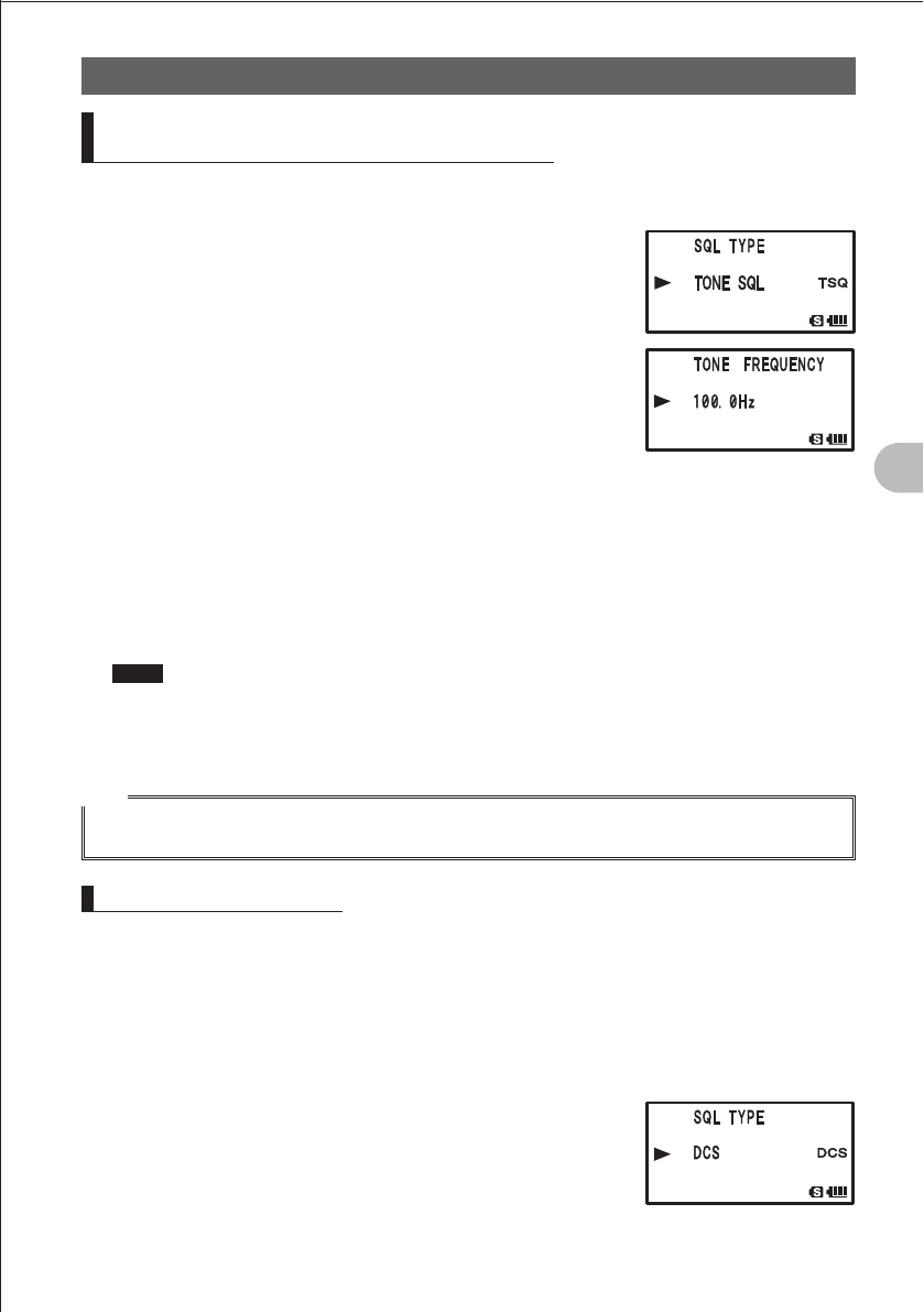
71
Communicating with a Specific Remote Station
Using the Tone Squelch Function
Searching for the Frequency of the
Tone Squelch Used by the Remote Station
The frequency of the tone squelch used by the remote station can be searched for and
displayed.
1 Press the M key more than 1 second.
The Set mode is selected.
2 Turn the O knob to select “4 SIGNALING”.
3 Press the M key briefly.
4 Turn the O knob to select “11 SQL TYPE”.
5 Press the M key briefly.
6 Turn the O knob to select “TONE SQL”.
7 Press the M key briefly.
8 Receive the signal from the remote station.
9 Press the B key more than 1 second.
“TONE SEARCH” is displayed.
10 Release the B key.
Search for the tone frequency starts.
When a coincident frequency is detected, a beep is emitted and search stops
temporarily. The detected tone frequency blinks.
Hints To set the found tone frequency, use the following procedure:
Press the B key. A beep is emitted. Press the M key more than 1 second.
Press the M key more than 1 second again.
The Set mode is canceled.
Hint
For the operation to perform when scanning stops, refer to “Selecting a Reception Method When
Scanning Stops” (See page 57).
Selecting a DCS Code
You can select a DCS code from among 104 DCS codes (023 to 754) (See page 170).
1 Specify the operating frequency.
2 Press the M key more than 1 second.
The Set mode is selected.
3 Turn the O knob to select “4 SIGNALING”.
4 Press the M key briefly.
5 Turn the O knob to select “2 DCS CODE”.
6 Press the M key briefly.
7 Turn the O knob to select a DCS code.
FCC ID: K6620445X20
IC: 511B-20445X20
YAESU MUSEN CO., LTD.
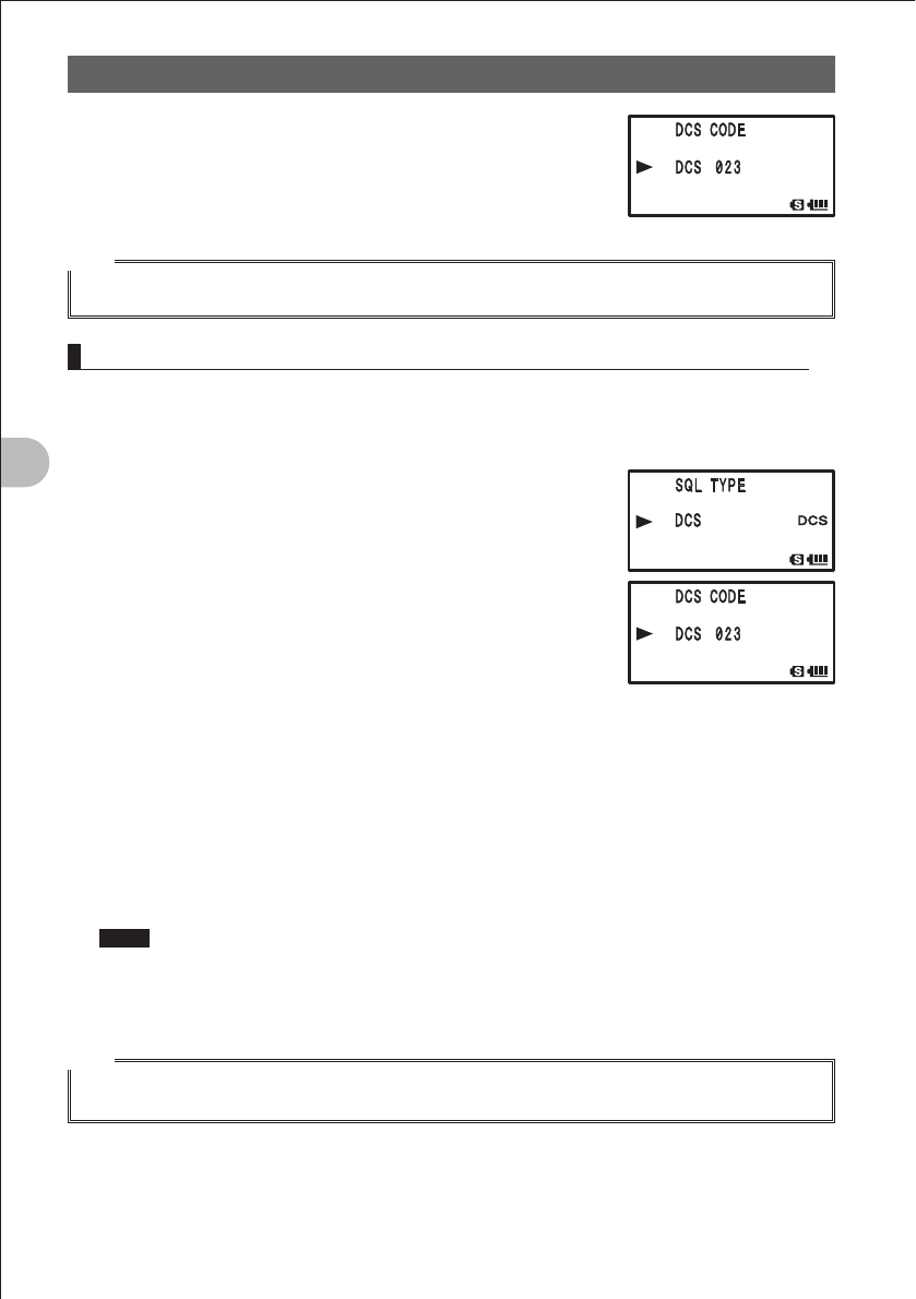
72
Communicating with a Specific Remote Station
Using the Tone Squelch Function
8 Press the M key more than 1 second.
The selected DCS code is determined.
9 Press the M key more than 1 second.
The Set mode is canceled.
Hint
• By default, the DCS code is set to “023”.
Searching for the Frequency of the DCS Used by the Remote Station
The DCS code used by the remote station can be searched for and displayed.
1 Press the M key more than 1 second.
The Set mode is selected.
2 Turn the O knob to select “4 SIGNALING”.
3 Press the M key briefly.
4 Turn the O knob to select “11 SQL TYPE”.
5 Press the M key briefly.
6 Turn the O knob to select “DCS”.
7 Press the M key briefly.
The selected DCS is determined.
8 Turn the O knob to select “2 DCS CODE”.
9 Press the M key briefly.
10 Receive the signal from the remote station.
11 Press the B key more than about 1 second.
“DCS SEARCH” is displayed.
12 Release the B key.
Search for the DCS code starts.
When a coincident DCS code is found, a beep is emitted and search stops
temporarily. The found DCS code blinks.
Hints To set the found DCS code, use the following procedure:
Press the B key. A beep is emitted. Press the M key more than 1 second.
Press the M key more than 1 second again.
The Set mode is canceled.
Hint
For the operation to perform when scan stops, refer to “Selecting a Reception Method When
Scanning Stops” (See page 57).
FCC ID: K6620445X20
IC: 511B-20445X20
YAESU MUSEN CO., LTD.
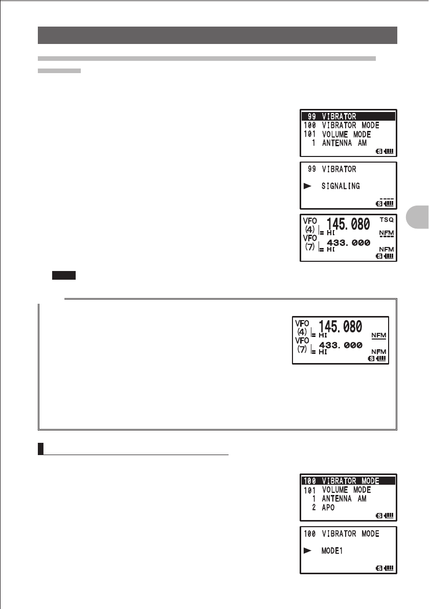
73
Communicating with a Specific Remote Station
Using the Tone Squelch Function
Notification of Call from the Remote Station by Vibration of the
Vibrator
Call from the remote station (reception of a signal containing a coincident tone or DCS)
can be notified by the vibrator.
1 Press the M key more than 1 second.
The Set mode is selected.
2 Turn the O knob to select “7 CONFIG”.
3 Press the M key briefly.
4 Turn the O knob to select “22 VIBRATOR”.
5 Press the M key briefly.
6 Turn the A knob to select “MODE”.
7 Turn the O knob to select “SIGNALING”.
8 Press the M key more than 1 second.
The vibrator function is activated.
9 Press the O key more than 1 second again.
The Set mode is canceled.
Hints To turn off the vibrator function, select “OFF” in step 6.
Hints
• The vibrator function can be set for all frequency bands belonging to A- and B-bands.
• Selecting “7 CONFIG” “23 VIBRATOR” “BUSY” in the Set
mode will cause the vibrator to start vibrating when the BUSY LED
lights upon receipt of a signal. A solid line () is displayed under
the mode indication on the LCD.
• If you operate a key while the vibrator is vibrating, the vibrator
stops vibrating and enters the suspended state. In this case, the
dashed line (----) or solid line () on the LCD blinks.
If the BUSY state is not held continuously more than 5 seconds, the suspended state is canceled.
• If the p switch is operated to change the communication mode from transmission to reception
when the vibrator is turned ON, the vibrator function is turned off for 5 seconds and the dashed line
(----) or solid line () on the LCD blinks.
Selecting a Vibrator Operation Mode
1 Press the M key more than 1 second.
The Set mode is selected.
2 Turn the O knob to select “7 CONFIG”.
3 Press the M key briefly.
4 Turn the O knob to select “22 VIBRATOR MODE”.
5 Press the M key briefly.
6 Turn the A knob to select “SELECT”.
FCC ID: K6620445X20
IC: 511B-20445X20
YAESU MUSEN CO., LTD.
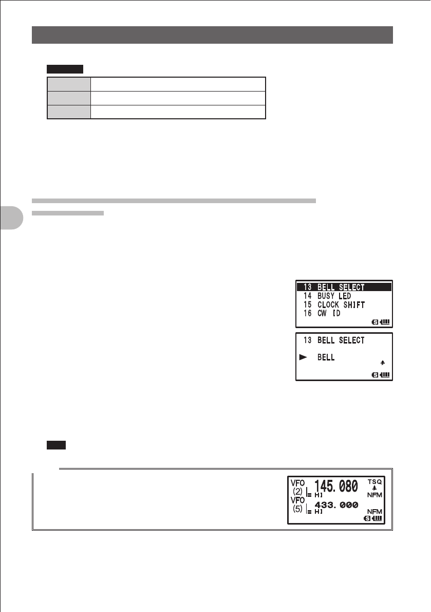
74
Communicating with a Specific Remote Station
Using the Tone Squelch Function
7 Turn the O knob to select a vibrator operation mode.
Remarks Default: MODE1
MODE1 The vibrator vibrates continuously.
MODE2 The vibrator operates at long intervals.
MODE3 The vibrator operates at short intervals.
8 Press the M key more than 1 second.
The selected vibrator mode is determined.
9 Press the M key more than 1 second again.
The Set mode is canceled.
Notification of Call from a Remote Station by the Bell
Bell Function
Call from a remote station (reception of a signal containing a coincident tone or DCS)
can be notified by the bell sound and the b icon blinking on the LCD.
1 Press the M key more than 1 second.
The Set mode is selected.
2 Turn the O knob to select “4 SIGNALING”.
3 Press the M key briefly.
4 Turn the O knob to select “1 BELL”.
5 Press the M key briefly.
6 Turn the A knob to select “RINGER”.
7 Turn the O knob to select “BELL”.
When the tone squelch or DCS function is turned on, the
b icon is displayed.
8 Press the M key more than 1 second.
The bell function is turned on.
9 Press the M key more than 1 second again.
The Set mode is canceled.
Hint To turn off the bell function, select “OFF” in step 6.
Hints
• To use the bell function, turn on the tone squelch or DCS function.
• The bell function cannot be used via the repeater.
• The b icon is displayed when the bell function is turned on.
Upon receipt of a signal from a remote station, the b icon blinks.
FCC ID: K6620445X20
IC: 511B-20445X20
YAESU MUSEN CO., LTD.
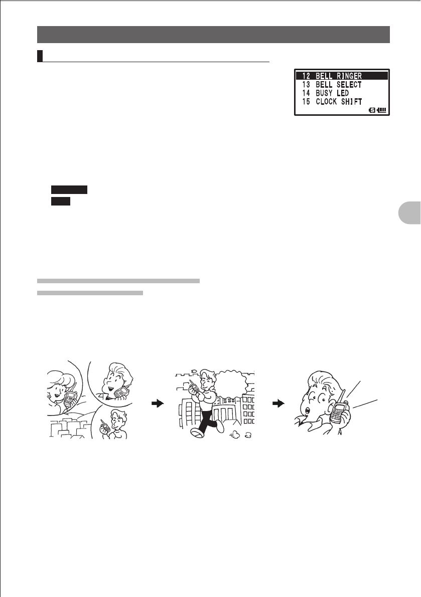
75
Communicating with a Specific Remote Station
Using the Tone Squelch Function
Changing the Number of Times the Bell Rings
1 Press the M key more than 1 second.
The Set mode is selected.
2 Turn the O knob to select “4 SIGNALING”.
3 Press the M key briefly.
4 Turn the O knob to select “1 BELL”.
5 Press the M key briefly.
6 Turn the A knob to select “SELECT”.
7 Turn the O knob to select a number of times the bell
rings.
Remarks Default: Once
Hint You can select the number of times the bell rings from among 1-20 and “continuous”.
8 Press the M key more than 1 second.
The selected number of times the bell rings is determined.
9 Press the M key more than 1 second again.
The Set mode is canceled.
Calling Only a Specific Station
New Pager Function
When using FT1DRs with your friends, specifying personal codes (each code is
composed of two CTCSS codes) allows only a specific station to be called. Even if the
called person is not near his or her FT1DR, the information on the LCD indicates that he
or she has been called.
A
C
B
Three persons A, B, and C
are using the FT1DR
Mr. C sends the personal
code of Mr. B.
Only Mr. B is called.
Well,
call Mr. B.
In
t
er
m
itt
ent
t
one
FCC ID: K6620445X20
IC: 511B-20445X20
YAESU MUSEN CO., LTD.
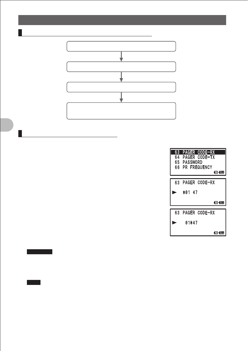
76
Communicating with a Specific Remote Station
Using the Tone Squelch Function
Flow of Operation to Use the Pager Function
Set the same code as that of the remote station.
Determine a frequency.
Perform transmission/reception.
Confirm reception according to the information
on the LCD and the bell sound
Setting the Code of Your Station
Set the “personal code (your code)” used to be called by other stations.
1 Press the M key more than 1 second.
The Set mode is selected.
2 Turn the O knob to select “4 SIGNALING”.
3 Press the M key briefly.
4 Turn the O knob to select “6 PAGER”.
5 Press the M key briefly.
6 Turn the A knob to select “CODE-RX”.
7 Turn the O knob to select a code.
Select the first code from among 1-50.
8 Press the B key briefly.
The cursor “¼” moves.
9 Turn the O knob to select a code.
Select the second code from among 1-50.
Precaution The second code must be different from the first code.
10 Press the M key more than 1 second.
The code of your station is determined.
11 Press the M key more than 1 second again.
Hints • Default: “05 47”
• The first and second codes contained in your personal code may be inverted, i.e., “05 47”
and “47 05” are recognized as being the same code.
• If the same personal code (group code) is specified for all persons, all persons can be called
at the same time.
FCC ID: K6620445X20
IC: 511B-20445X20
YAESU MUSEN CO., LTD.
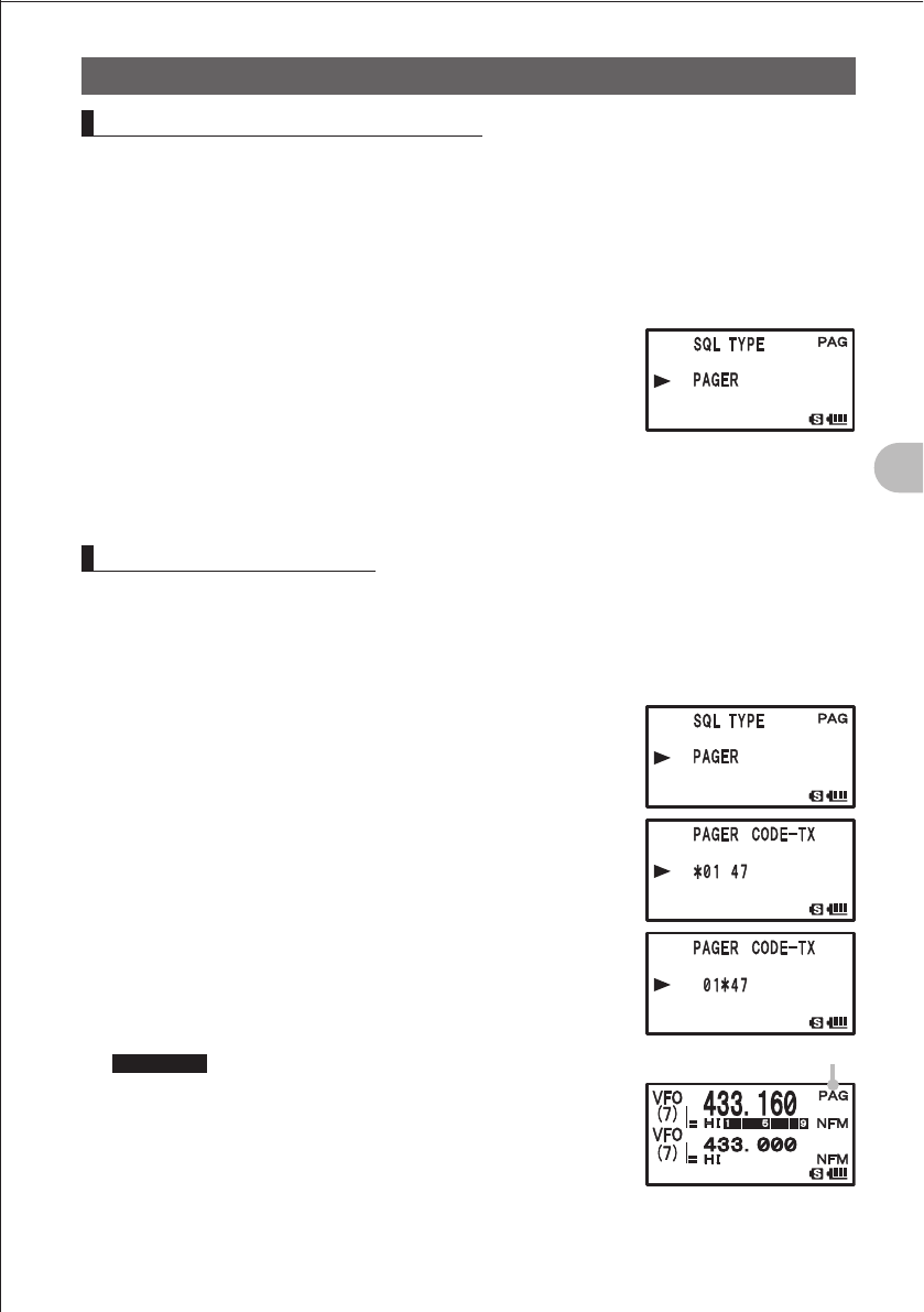
77
Communicating with a Specific Remote Station
Using the Tone Squelch Function
Turning on the New Pager Function
1 Press the M key more than 1 second.
The Set mode is selected.
2 Turn the O knob to select “4 SIGNALING”.
3 Press the M key briefly.
4 Turn the O knob to select “11 SQL TYPE”.
5 Press the M key briefly.
6 Turn the O knob to select “PAGER”.
7 Press the M key briefly.
The new pager function is turned on.
8 Press the M key more than 1 second.
9 Press the M key more than 1 second again.
The Set mode is canceled.
Thus, you can “call” or “wait” a remote station using the new pager function.
Calling a Specific Station
1 Press the M key more than 1 second.
The Set mode is selected.
2 Turn the O knob to select “4 SIGNALING”.
3 Press the M key briefly.
4 Turn the O knob to select “11 SQL TYPE”.
5 Press the M key briefly.
6 Turn the O knob to select “PAGER”.
7 Press the M key briefly.
The new pager function is selected.
8 Turn the O knob to select “4 SIGNALING”.
9 Press the M key briefly.
10 Turn the O knob to select “6 PAGER”.
11 Press the M key briefly.
12 Turn the A knob to select “CODE-TX”.
13 Turn the O knob to select the code of the remote station.
Select the first code of the remote station.
Precaution Register the pager code of the remote station in
advance.
14 Press the B key briefly.
The cursor “¼” moves.
15 Turn the O knob to select the code of the remote station.
Select the second code of the remote station.
PAG is displayed.
FCC ID: K6620445X20
IC: 511B-20445X20
YAESU MUSEN CO., LTD.

78
Communicating with a Specific Remote Station
Using the Tone Squelch Function
16 Press the M key more than 1 second.
The code is determined.
17 Press the M key more than 1 second again.
The Set mode is canceled.
18 Press the p key.
Call the remote station.
Being Called by the Remote Station (Standby Operation)
If you use the new pager function at the same frequency as that of the remote station,
“PAG” displayed on the LCD changes to “PIN”, allowing you to check that you have
been called by the remote station. In addition, if you turn on the “bell function (See page
140)”, you can confirm call by the remote station by the “PAG” display, the blinking b
icon, and the bell sound. In addition, if you turn on the “vibrator function (See page 139),
you can confirm call by the remote station by vibration of the vibrator.
Hint
Selecting “4 SIGNALING” “9 PAGER ANS-BACK” “ON” in the Set mode places the FT1DR in
the transmission state (for about 2.5 seconds) automatically when called by the remote party and
notifies the remote party of getting ready for communication.
FCC ID: K6620445X20
IC: 511B-20445X20
YAESU MUSEN CO., LTD.
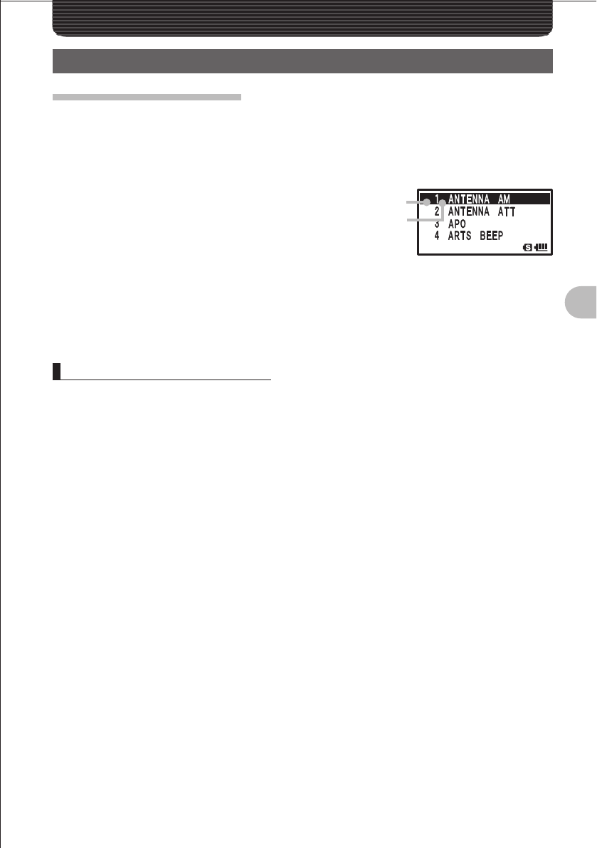
79
Functions Used As Needed
Functions Used As NeededFunctions Used As Needed
Set Mode
Selecting Set Mode Items
The Set mode allows you to select various functions from lists so that you can use your
FT1DR more conveniently.
1 Press the M key more than 1 second.
The Set mode is selected.
2 Turn the O knob to select a Set mode
item.
3 Press the M key briefly.
4 Turn the O knob to select an option.
Select an option.
5 Press the M key more than 1 second.
6 Press the M key more than 1 second again.
The Set mode is canceled.
Resetting the Set Mode Items
The Set mode items you have set can be restored to the defaults by following the
procedure described below. However, to restore the following items to the defaults, all
resetting (See page 15) is required.
Set mode item
7 BANK NAME 15 CLOCK SHIFT
16 CW ID 21 DCS CODE
22 DCS INVERSION 25 DTMF SELECT
29 EMERGENCY SELECT 33 HALF DEVIATION
38 INTERNET CODE 41 INTERNET SELECT
48 MENORY FAST STEP 49 MENORY NAME
51 MENORY SKIP 55 MESSAGE SELECT
63 PAGER CODE-RX 64 PAGER CODE-TX
71 RPT SHIFT 72 RPT SHIFT FREQ
90 SQL TYPE 93 TONE FREQUENCY
APRSR/GPS Set mode items
5 APRS MSG TXT 13 BEACON STATS TXT
16 DIGI PATH 21 MSG GROUP
22 MY CALLSIGN 23 MY POSITION
24 MY SYMBOL
Set mode item No.
Set mode item
FCC ID: K6620445X20
IC: 511B-20445X20
YAESU MUSEN CO., LTD.
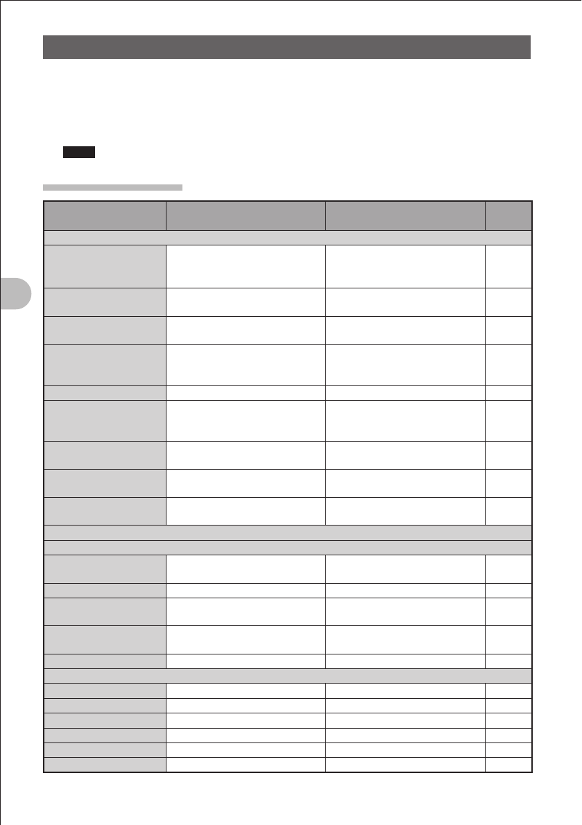
80
Functions Used As Needed
Set Mode
1 While pressing the % and V keys, press the P key.
The FT1DR is turned on. When a beep is heard, release the keys.
2 When “SET MODE RESET PUSH F KEY” is displayed, press the F key.
A beep is emitted.
Hints To cancel resetting, press any key other than the F key.
Set Mode Item List
Set mode item No./Item Description of function Option
(Bold letters: Default)
Reference
page
1 DISPLAY
1-1 DISPLAY SELECT
Display/hide the GPS screen
each time the M key is pressed
briefly.
GPS ON / GPS OFF
1-2 BAND SCOPE
Select a spectrum analyzer
operation mode.
ONCE / CONTINUOUS / FULL
TIME
1-3 LAMP
Set the time during which the
backlight and keys stay lit.
OFF / 2-10 SEC(KEY) /
CONTINUOUS
1-4 LANGUAGE
Select Japanese or English as
the display language for Set
mode items, options, etc.
JAPANESE / ENGLISH
1-5 LCD CONTRAST
Set the LCD contrast level. LEVEL 1 to LEVEL 15
1-6 LCD DIMMER
Set the brightness level of the
LCD backlight and keypad key
light.
LEVEL 1 to LEVEL 6
1-7 OPENING MESSAGE
Select an opening message type. NORMAL / OFF / DC /
MESSAGE / CALLSIGN
1-8 SENSOR INFO
Voltage/temperature display
function
VOLTAGE & TEMPERATURE
1-9 S-METER SYNBOL
Select a S/PO meter symbol
display type.
4 types
2 TX / RX
2-1 MODE
2-1-1 ANTENNA AM
Select an AM radio antenna type. BAR & EXT. ANTEANN/BAR
ANTENNA
2-1-2 ANTENNA ATT
Turn on/off the attenuator. OFF / ON
2-1-3 FULL DUPLEX
Turn on/off the full duplex
function.
OFF / ON
2-1-4 HALF DEVIATION
Set the transmission modulation
level.
OFF / ON
2-1-5 RX MODE
Select a reception mode. AUTO / NFM / AM
2-2 DIGITAL
2-2-1 DIGITAL MODE
T.B.D. T.B.D.
2-2-2 SQL TYPE
T.B.D. T.B.D.
2-2-3 MY CALLSIGN SEL
T.B.D. T.B.D.
2-2-4 MY CALLSIGN
T.B.D. T.B.D.
2-2-5 DISTINATION
T.B.D. T.B.D.
2-2-6 TEXT
T.B.D. T.B.D.
FCC ID: K6620445X20
IC: 511B-20445X20
YAESU MUSEN CO., LTD.
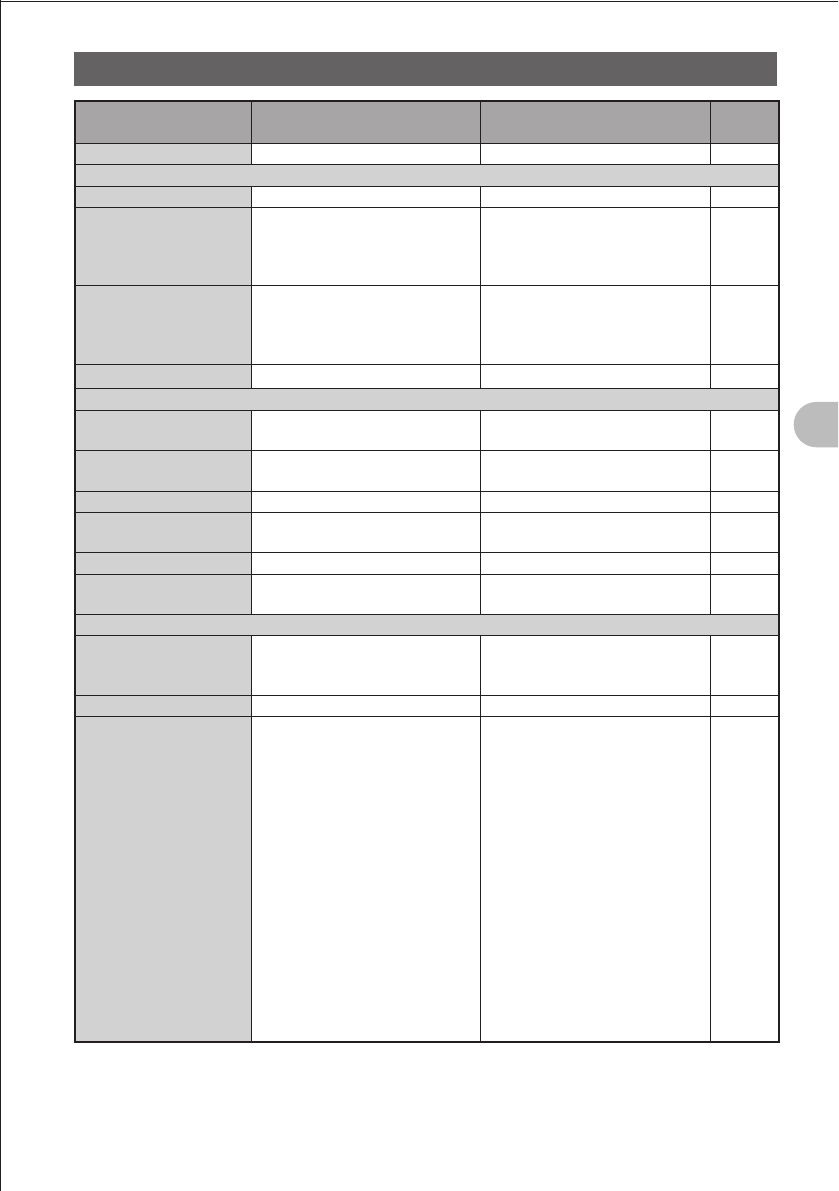
81
Functions Used As Needed
Set Mode
Set mode item No./Item Description of function Option
(Bold letters: Default)
Reference
page
2-2-7 DSP Ver
T.B.D. T.B.D.
2-3 AUDIO
2-3-1 MIC GAIN
Adjust the microphone level. LEVEL 1 to LEVEL 9
2-3-2 MUTE
Set the muting level on the non-
operating side when a signal is
received on the operating band
side.
OFF / MUTE 30% /
MUTE 50% / MUTE 100%
2-3-3 RX AF DUAL
Select a mode for simultaneous
reception of a radio broadcast.
1-SEC COMMUNICATION to
10-SEC COMMUNICATION/
FIXED / 1-SEC TRANSMISSION
to 10-SEC TRANSMISSION
2-3-4 VOL MODE
Select a v key function. NORMAL / AUTO BACK
3 MEMORY
3-1 BANK LINK
Set up a memory bank. BANK 1 to BANK 24, BANK LINK
ON / OFF
3-2 BANK NAME
Assign a name to a memory
bank.
BANK 1 to BANK 24
3-3 MEMORY NAME
Write a memory tag. Max. 16 characters
3-4 MEMORY PROTECT
Enable/disable writing into the
memory.
OFF / ON
3-5 MEMORY SKIP
Assign a skip/selected memory. OFF / SKIP / SELECT
3-6 MEMORY WRITE
Select an auto increment mode
for memory writing.
NEXT / LOWER
4 SIGNALING
4-1 BELL
Set up the bell function. RINGER: OFF / BELL
SELECT: ONCE to 20 TIMES/
CONTINUOUS
4-2 DCS CODE
Select a DCS code DCS 023 to DCS 754
4-3 DCS INVERSION
Select a combination of DCS
inversion codes in terms of
communication direction.
RECEPTION – IN-PHASE,
TRANSMISSION – IN-PHASE
RECEPTION –
INVERTED PHASE,
TRANSMISSION – IN-PHASE
RECEPTION – BOTH-PHASE,
TRANSMISSION – IN-PHASE
RECEPTION – IN-PHASE,
TRANSMISSION –
INVERTED PHASE
RECEPTION – INVERTED
PHASE,
TRANSMISSION –
INVERTED PHASE
RECEPTION – BOTH-PHASE,
TRANSMISSION –
INVERTED PHASE
FCC ID: K6620445X20
IC: 511B-20445X20
YAESU MUSEN CO., LTD.
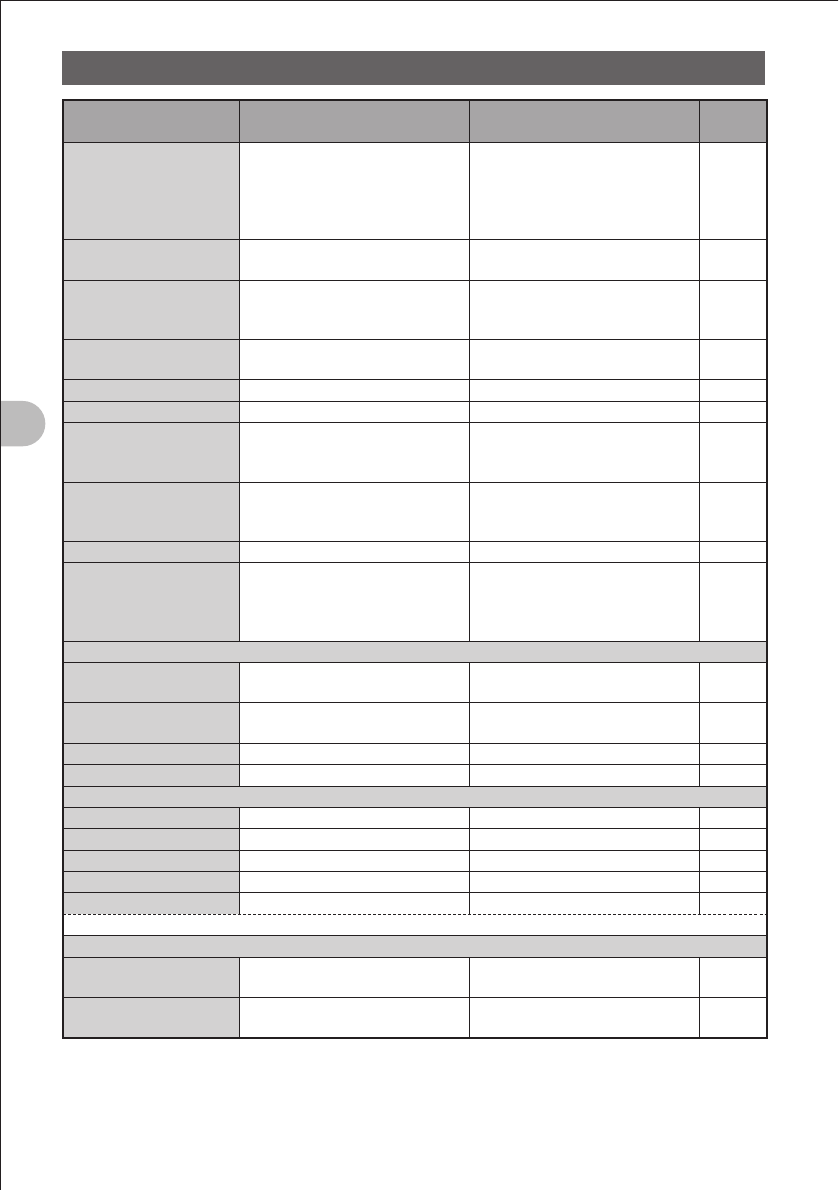
82
Functions Used As Needed
Set Mode
Set mode item No./Item Description of function Option
(Bold letters: Default)
Reference
page
4-4 DTMF MODE
Select a DTMF memory sending
mode.
Select a DTMF sending delay
time.
Select a DTMF sending time.
MODE: MANUAL / AUTO
DELAY: 50ms / 250ms / 450ms /
750ms / 1000ms
SPEED: 50ms / 100ms
4-5 DTMF SELECT
Select a DTMF auto dialer
channel or code (16 characters).
1 to 10
4-6 PAGER
Turn on/off the pager answerback
function and specify a personal
code (transmission/reception).
ANS-BACK: OFF / ON
CODE-RX: 01 02 to 50 49
CODE-TX: 01 02 to 50 49
4-7 PR FREQUENCY
Select a no-communication
squelch frequency.
300 Hz to 3000 Hz
4-8 SQL LEVEL
Select a squelch level. LEVEL 0 to LEVEL 15
4-9 SQL S-METER
Select an S-meter squelch level. OFF/LEVEL 1 to LEVEL 9
4-10 SQL EXPANTION
Enable or disable selection
of different squelch types for
transmission and reception.
OFF / ON
4-11 SQL TYPE
Select a squelch type. OFF / TONE / TONE SQL / DCS /
REV TONE / JR FREQ /
PR FREQ / PAGER
4-12 TONE SQL FREQ
Select a tone frequency. 67.0Hz to 254.1Hz
4-13 TONE-SRCH
Enable or disable emission of
tone during tone search.
Turn on/off the muting function
and select a tone search speed.
MUTE: ON / OFF
SPEED: HIGH / LOW
5 SCAN
5-1 PRI TIME
Select a priority channel
monitoring interval.
0.1 SEC to 10 SEC
5-2 SCAN LAMP
Turn the lamp on/off when
scanning stops.
ON / OFF
5-3 SCAN RE-START
Set a scanning restart time. 0.1 SEC to 10 SEC
5-4 SCAN RESUME
Select a scanning stop mode. BUSY / HOLD / 2 SEC to 10 SEC
6 ARTS / WiRES
6-1 WiRES MANU/AUTO
T.B.D. T.B.D.
6-2 WiRES CODE
T.B.D. T.B.D.
6-3 WiRES KEY
T.B.D. T.B.D.
6-4 WiRES MODE
T.B.D. T.B.D.
6-5 WiRES SELECT
T.B.D. T.B.D.
* For more details on functions, refer to the included CD-ROM.
7 CONFIG
7-1 APO
Set the APO operating time. OFF / 30 MIN /1 HOUR 00 MIN
to 12 HOURS 00 MIN
7-2 BCLO
Turn on the busy channel lockout
function.
OFF / ON
FCC ID: K6620445X20
IC: 511B-20445X20
YAESU MUSEN CO., LTD.
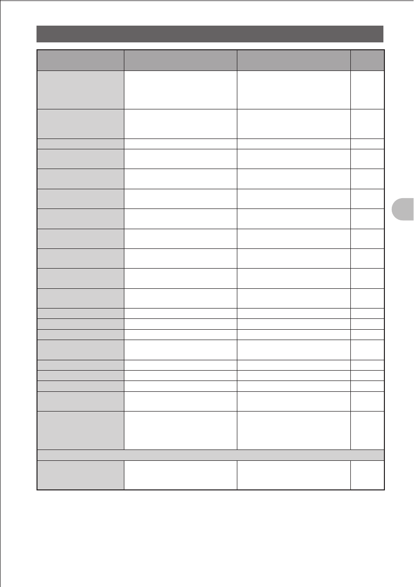
83
Functions Used As Needed
Set Mode
Set mode item No./Item Description of function Option
(Bold letters: Default)
Reference
page
7-3 BEEP
Set up the beep output function
and the function of emitting a
beep when a band edge/CH1 is
encountered.
SELECT:
KEY&SCAN / KEY / OFF
EDGE: OFF / ON
7-4 BUSY LED
Turn on/off the BUSY LED A BAND: ON / OFF
B BAND: ON / OFF
RADIO: ON / OFF
7-5 CLOCK TYPE
Select a clock type. A / B
7-6 GPS LOG
Set the duration of GPS access. OFF / 1 SEC / 2 SEC / 5 SEC /
10 SEC / 30 SEC / 60 SEC
7-7 HOME VFO
Enable/disable VFO transfer via
the home channel.
ENABLE / DISABLE
7-8 LED LIGHT
Turn on/off the white LED
flashlight.
WHITE LED ON
7-9 LOCK
Select a lock mode. KEY&DIAL / PTT / KEY&PTT /
DIAL&PTT / ALL / KEY / DIAL
7-10 MONI/T-CALL
Select a monitor switch or
T-CALL switch.
MONI / T-CALL
7-11 TIMER
Set the power ON/OFF timer. ON: 00:00 to 23:59 ON / OFF
OFF: 00:00 to 23:59 ON / OFF
7-12 PASSWORD
Turn on/off the password
function.
ON / OFF [ – – – – ]
7-13 PTT DELAY
Set the PTT delay time. OFF / 20ms / 50ms / 100ms /
200ms
7-14 RPT ARS
Turn on/off the ARS function. ON / OFF
7-15 RPT SHIFT
Select a repeater shift direction. SIMPLEX / –RPT / +RPT
7-16 RPT SHIFT FREQ
Select a repeater shift width. 0.000 MHz to 150.000 MHz
7-17 SAVE RX
Set the reception save time. OFF / 0.2 SEC (1:1) to 60.0 SEC
(1:300)
7-18 STEP
Select a channel step. AUTO / 5.0KHZ to 100KHz
7-19 DATE & TIME ADJ
Set up the built-in clock function. –
7-20 TOT
Set the timeout timer. OFF / 30 SEC to 10 MIN 00 SEC
7-21 VFO MODE
Select the frequency selection
range in the VFO mode.
ALL / BAND
7-22 VIBRATOR
Select a vibrator mode and set up
the vibrator function.
MODE:
OFF / BUSY / SIGNALING
SELECT:
MODE1 / MODE2 / MODE3
8 APRS
8-1 APRS AF DUAL
Turn on/off the muting function
when both the APRS function and
AF dual function are active.
ON / OFF
FCC ID: K6620445X20
IC: 511B-20445X20
YAESU MUSEN CO., LTD.
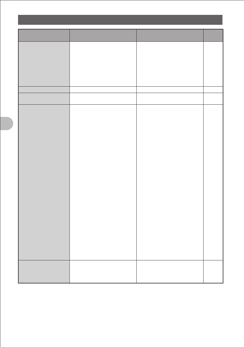
84
Functions Used As Needed
Set Mode
Set mode item No./Item Description of function Option
(Bold letters: Default)
Reference
page
8-2 APRS FILTER
Select a filter function. Mic-E: ON / OFF
POSITION: ON / OFF
WEATHER: ON / OFF
OBJECT: ON / OFF
ITEM: ON / OFF
STATUS: ON / OFF
OTHER: OFF / ON
ALTNET: ON / OFF
8-3 APRS MODEM
Select an APRS baud rate. OFF / 1200bps / 9600bps
8-4 APRS MUTE
Turn on/off the B-band AF muting
function when APRS is set.
ON / OFF
8-5 APRS POPUP
Select a pop-up beacon type. Mic-E:
OFF / ALL 2s to ALL 60s /
ALLCNT / BND2s to BND60s /
BNDCNT
POSITION:
OFF / ALL2s to ALL60s /
ALLCNT / BND2s to BND60s /
BNDCNT
WEATHER:
OFF / ALL2s to ALL60s /
ALLCNT / BND2s to BND60s /
BNDCNT
OBJECT:
OFF / ALL2s to ALL60s /
ALLCNT / BND2s to BND60s /
BNDCNT
ITEM:
OFF / ALL2s to ALL60s /
ALLCNT / BND2s to BND60s /
BNDCNT
STATUS:
OFF / ALL2s to ALL60s /
ALLCNT / BND2s to BND60s /
BNDCNT
OTHER:
OFF / ALL2s to ALL60s /
ALLCNT / BND2s to BND60s /
BNDCNT
8-5 APRS POPUP
Select a pop-up beacon type. MY PACKET:
OFF / ALL2s to ALL60s /
ALLCNT / BND2s to BND60s /
BNDCNT
FCC ID: K6620445X20
IC: 511B-20445X20
YAESU MUSEN CO., LTD.

85
Functions Used As Needed
Set Mode
Set mode item No./Item Description of function Option
(Bold letters: Default)
Reference
page
8-6 APRS RINGER
Turn on/off the bell when a
beacon is received.
Mic-E: ON / OFF
POSITION: ON / OFF
WEATHER: ON / OFF
OBJECT: ON / OFF
ITEM: ON / OFF
STATUS: ON / OFF
OTHER: ON / OFF
MY PACKET: ON / OFF
8-7 APRS UNIT
Select the units for APRS display. Position: MM.MM' / MM'SS'
Distance: km / mile
Speed: km/h / knot / mph
Altitude: m / ft
Temp: ºC / ºF
Rain: mm / inch
Wind: m/s / mph
8-8 APRS TX DELAY
Set the data sending delay time. 100ms / 150ms / 200ms /
250ms / 300ms / 400ms /
500ms / 750ms / 1000ms
8-9 BEACON INFO
T.B.D. AMBIGUITY:
OFF / 1 dig to 4 dig
SPD / CSE: ON / OFF
ALTITUDE: ON / OFF
8-10 BEACON INTERVAL
Set a beacon automatic sending
interval.
30sec / 1min / 2min / 3min /
5min / 10min / 15min / 20min /
30min / 60min
8-11 BEACON STATS TXT
Make settings for status text
entry.
S.TXT: ON / OFF
TX RATE: 1/1 to 1/8
1 to 5 CH
8-12 BEACON TX
Select automatic or manual
sending of beacon.
AUTO / MANUAL
8-13 COM PORT SETTING
Set up the COM port. STATUS: ON / OFF
SPEED:
4800 / 9600 / 19200 / 38400
INPUT: OFF / GPS
8-14 DIGI PASS
Select a digipeater route. P1 OFF
P2 1 WIDE1-1
P3 1 WIDE1-1 / 2 WIDE2-1
P4・・・・・・ – ・・
P5・・・・・・ – ・・
P6・・・・・・ – ・・
P7・・・・・・ – ・・
P8・・・・・・ – ・・
8-15 GPS DATUM
Select a datum used for the GPS
function.
WGS-84 / Tokyo Mean /
Tokyo Japan / Tokyo Korea /
Tokyo Okinawa
8-16 GPS POWER
Turn on/off the GPS function. GPS ON / GPS OFF
8-17 GPS TIME SET
Turn on/off the GPS time and
date automatic acquisition
function.
AUTO / MANUAL
FCC ID: K6620445X20
IC: 511B-20445X20
YAESU MUSEN CO., LTD.
86
Functions Used As Needed
Set Mode
Set mode item No./Item Description of function Option
(Bold letters: Default)
Reference
page
8-18 GPS UNIT
Select the units for GPS display. Position: .MMM' / 'SS''
Speed: Km/h / Knot / mph
Altitude: m / ft
8-19 MY CALLSIGN
Specify the call sign of your
station. –
8-20 MY POSITION
Set the location of your station. GPS / Lat N * **°**.**' /
P1 to P10
8-21 MY SYMBOL
Set the symbol of your station. 64 Icon
8-22 POSITION COMMENT
Set up the position comment
function.
Off Duty / En Route / In Service /
Returning / Committed / Special /
Priority / Custom 0 to 6 /
EMERGENCY!
8-23 SmartBeaconing
Set up the smart beaconing
function.
STATUS:
OFF / TYPE1 / TYPE2 / TYPE3
LOW SPD: 2Km/h to 30Km/h
HIGH SPD: 31Km/h to 70Km/h
SLOW RATE: 1min to 100min
FAST RATE: 10sec to 180sec
TURN ANGL: 5° to 90°
TURN SLOP: 1 to 255
TURN TIME: 5sec to 180sec
8-24 TIME ZONE
Set the time zone. UTC ± 13.0 H
* For more details of functions, refer to the included CD-ROM.
9 SD CARD
9-1 FORMAT
Initialize the micro SD memory
card.
Format the micro SD memory
card.
9-2 STORE/RECALL
Write or read the information
about your FT1DR into or from
the micro SD memory card.
STORE: Copy the information
about your FT1DR to the micro
SD memory card.
RECALL: Read data from the
micro SD memory card and
write it over the existing
information about your FT1DR.
10 OPTION
10-1 MH-85
T.B.D. T.B.D.
FCC ID: K6620445X20
IC: 511B-20445X20
YAESU MUSEN CO., LTD.

87
FT1DR Specifications
FT1DR Specifications
General
Frequency Range: RX:
TX:
0.5 - 1.8 MHz, 1.8 - 30 MHz,
30 - 76 MHz, 76 - 108 MHz,
108 - 137 MHz, 137 - 174 MHz,
174 - 222 MHz, 222 - 420 MHz,
420 - 470 MHz, 800 - 999 MHz (Cellular Blocked)
144 - 148 MHz,
430 - 450 MHz
Channel Steps: 5/6.25/8.33/9/10/12.5/15/20/25/50/100 kHz
Mode of Emission: F1D, F2D, F3E, F7W
Antenna Impedance: 50 Ω, unbalanced
Frequency Stability: ±2.5 ppm (10 °C to +50 °C)
Operating Temperature Range: 20 °C to +60 °C
Supply Voltage: 7.4 V DC (Rated), 4 - 9 V DC (Battery Input),
11 - 16 V DC (EXT DC Input)
Current Consumption (Approx.):
RX:
TX:
250 mA (Analog / Mono Band)
350 mA (Digital / Mono Band)
1.7 A (144 MHz / Analog)
1.8 A (144 MHz / Digital)
2.0 A (430 MHz / Analog)
2.1 A (430 MHz / Digital)
Case Size (W × H × D): 60(W) × 95(H) × 28(D) mm (w/o knobs & antenna)
Weight (Approx.): 250g (with Battery & Antenna)
Transmitter
Output Power: 5 W (144 / 430 MHz), 2.5 W (144 / 430MHz)
1.0 W (144 / 430 MHz), 0.1 W (144 / 430MHz)
Modulation Type: Variable Reactance
Maximum Deviation: ±5 KHz,
Spurious Radiation: better than 60 dB
Modulation Distortion: less than 3%
Microphone Impedance: 2 kΩ
Receiver
Circuit Type: Double-conversion super heterodyne (N-FM / AM)
Intermediate Frequency: 1st: A- Band 47.25 MHz (N-FM / AM)
1st: B- Band 46.35 MHz (N-FM / AM)
2nd: 450 kHz (N-FM / AM)
FCC ID: K6620445X20
IC: 511B-20445X20
YAESU MUSEN CO., LTD.

88
FT1DR Specifications
FT1DR Specifications
Sensitivity (for 12dB SINAD): 0.5 - 30 MHz: 3.00
μ
V (10 dB S/N, AM)
30 - 54 MHz: 0.35
μ
V (12 dB SINAD, N-FM)
54 - 76 MHz: 1.00
μ
V (12 dB SINAD, N-FM)
76 - 108 MHz: 1.50
μ
V (12 dB SINAD, N-FM)
108 - 137 MHz: 1.50
μ
V (10 dB S/N, AM)
137 - 140 MHz: 0.20
μ
V (12 dB SINAD, N-FM)
140 - 150 MHz: 0.16
μ
V (12 dB SINAD, N-FM)
150 - 174 MHz: 0.20
μ
V (12 dB SINAD, N-FM)
174 - 222 MHz: 1.00
μ
V (12 dB SINAD, N-FM)
300 - 350 MHz: 0.50
μ
V (12 dB SINAD, N-FM)
350 - 400 MHz: 0.20
μ
V (12 dB SINAD, N-FM)
400 - 470 MHz: 0.18
μ
V (12 dB SINAD, N-FM)
470 - 540 MHz: 1.50
μ
V (12 dB SINAD, W-FM)
540 - 800 MHz: 3.00
μ
V (12 dB SINAD, N-FM)
800 - 999 MHz: 1.50
μ
V (12 dB SINAD, N-FM)
(USA Version Cellular Blocked)
Selectivity (6dB/60dB): 15 kHz / 35 kHz (N-FM/AM)
Maximum AF Output: 400 mW @ 13.8V, 10% THD
200 mW @ 7.4V, 10% THD
AF Output Impedance: 8 Ω
FCC ID: K6620445X20
IC: 511B-20445X20
YAESU MUSEN CO., LTD.

89
1. Changes or modifications to this device not expressly approved by YAESU
MUSEN could void the user’s authorization to operate this device.
2. This device complies with part 15 of the FCC Rules. Operation is subject to the
following two conditions; (1) this device may not cause harmful interference,
and (2) this device must accept any interference including interference that may
cause undesired operation.
3. The scanning receiver in this equipment is incapable of tuning, or readily being
altered, by the User to operate within the frequency bands allocated to the
Domestic public Cellular Telecommunications Service in Part 22.
Part 15.21: Changes or modifications to this device not expressly approved by
YAESU MUSEN could void the user’s authorization to operate this device.
DECLARATION BY MANUFACTURER
The Scanner receiver is not a digital scanner and is incapable of being converted or
modified to a digital scanner receiver by any user.
WARNING: MODIFICATION OF THIS DEVICE TO RECEIVE CELLULAR
RADIOTELEPHONE SERVICE SIGNALS IS PROHIBITED UNDER FCC RULES
AND FEDERAL LAW.
FCC ID: K6620445X20
IC: 511B-20445X20
YAESU MUSEN CO., LTD.

Copyright 2012
YAESU MUSEN CO., LTD.
All rights reserved.
No portion of this manual
may be reproduced
without the permission of
YAESU MUSEN CO., LTD. Printed in Japan
FCC ID: K6620445X20
IC: 511B-20445X20
YAESU MUSEN CO., LTD.