Yaesu Musen 30573X30 HANDHELD MARINE TRANSCEIVER User Manual 5
Yaesu Musen Co., Ltd. HANDHELD MARINE TRANSCEIVER 5
Contents
- 1. User Manual
- 2. User Manual 2
- 3. User Manual 3
- 4. User Manual 4
- 5. User Manual 5
User Manual 5

Page 96
HX870
14.12 SUMMARY OF THE DSC SETUP MENU
Item Description Default Value
INDIVIDUAL DIR. Sets addresses used for individual call −
INDIVIDUAL REPLY Selects a reply to individual call MANUAL
INDIVIDUAL ACK. Selects the message to be sent automati-
cally as an individual call acknowledge-
ment
ABLE TO COMPLY
INDIVIDUAL RING Selects the ringing time when an individual
call or a position request 2 min
GROUP DIR. Sets addresses used for group call −
POSITION REPLY Selects a reply to position request AUTO
AUTO POS POLLING Switches on and off of the AUTO POS
POLLING function AUTO POS REQUEST
AUTO POS INTERVAL Sets the transmission interval of AUTO
POS POLLING signal 5 min
AUTO CH CHANGE Selects the delay time to move to the
requested channel automatically after
receiving a distress call, All Ship call, or
group call
30 s
POS UNFIX WAIT Sets the maximum wait time till obtaining
a position information when receiving a
distress call, POS Report call, or acknowl-
edgement to POS request call
15 s
DSC BEEP Switches on and off of the alarm sound
when receiving a DSC call INDIVI.: On
All Ship: On
GROUP: On
POS RQ.: Off
POS RP: Off
Geog.: On
Polling: On
Test Call: On
Page 97
HX870
15 GPS SETUP
The “GPS Setup” mode allows the parameters for the HX870 internal GPS unit
to be custom-congured for your operating requirements.
15.1 GPS ON/OFF
This selection allows the internal GPS unit to be turned on or off to conserve
battery power. The default setting is “ON”.
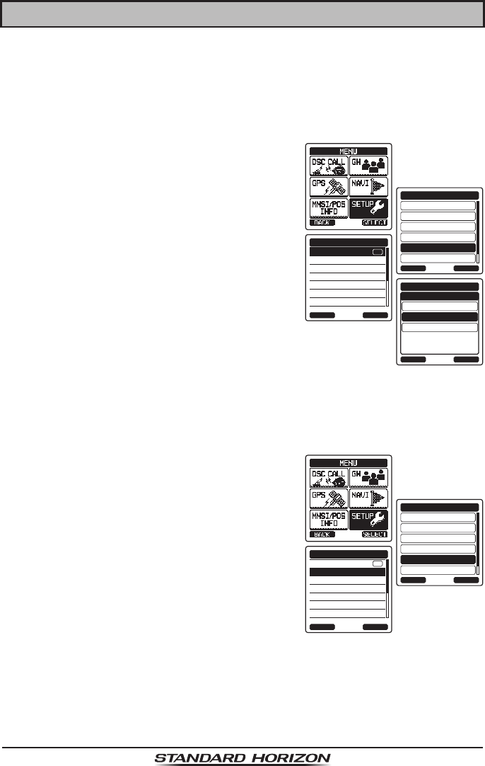
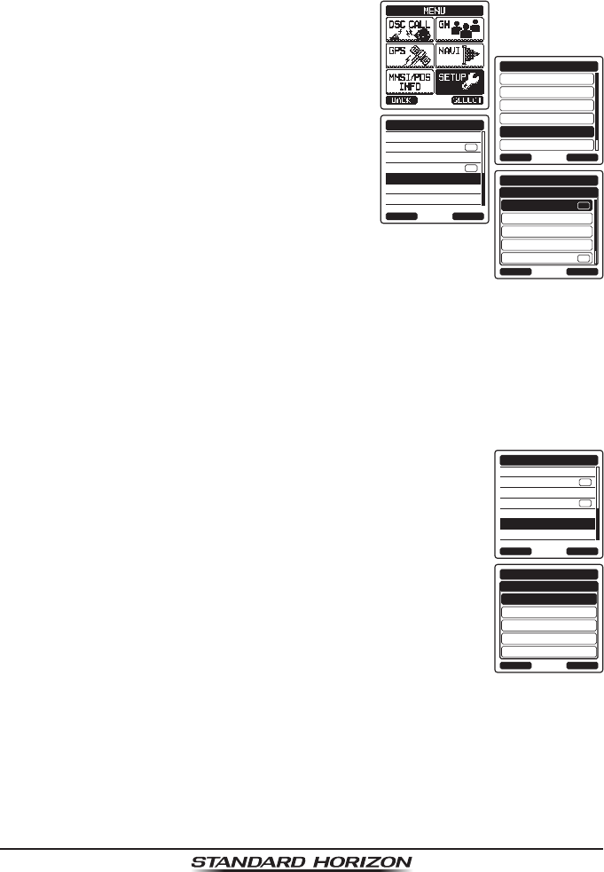
1. Press the MENU key to display “MENU”, then
select “SETUP” with the CH▲/CH▼/◄/►
key.
DSC SETUP
GM SETUP
BACK
SETUP
WAYPOINT SETUP
CH SETUP
GPS SETUP
ATIS SETUP
SELECT
GPS ON/OFF
POWER SAVE
DIRECTION
LOCATION FORMAT
TIME OFFSET
TIME AREA
TIME FORMAT
GPS SETUP
BACK SELECT
ON
OFF
GPS SETUP
ON
INT at PWR OFF
GPS ON/OFF
BACK ENTER
2. Press the CH▲/CH▼ key to select “GPS
SETUP” menu.
3. Press the [SELECT] soft key, then select
“GPS ON/OFF” with the CH▲/CH▼ key.
4. Press the [SELECT] soft key.
5. Press the CH▲/CH▼ key to select “ON”.
6. Press the [ENTER] soft key to save the new
setting.
7. Press the CLR key to return to radio opera-
tion.
15.2 POWER SAVE
This menu item selects the Battery Save Mode for the internal GPS unit. The
default setting for the Power Save Mode is “AUTO”.
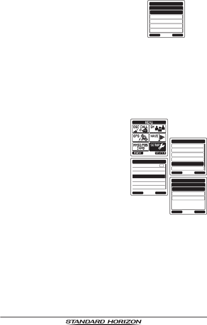
1. Press the MENU key to display “MENU”, then
select “SETUP” with the CH▲/CH▼/◄/►
key.
DSC SETUP
GM SETUP
BACK
SETUP
WAYPOINT SETUP
CH SETUP
GPS SETUP
ATIS SETUP
SELECT
GPS ON/OFF
POWER SAVE
DIRECTION
LOCATION FORMAT
TIME OFFSET
TIME AREA
TIME FORMAT
GPS SETUP
BACK SELECT
ON
2. Press the CH▲/CH▼ key to select “GPS
SETUP” menu.
3. Press the [SELECT] soft key, then select
“POWER SAVE” with the CH▲/CH▼ key.
4. Press the [SELECT] soft key.
Page 98
HX870
5. Press the CH▲/CH▼ key to select the
desired level.
OFF: GPS Signals are always being
received.
AUTO: Activates the GPS receiver automati-
cally when GPS signals are received.
OFF
BACK
GPS SETUP
50%
70%
80%
90%
ENTER
POWER SAVE
50%: Activates the GPS receiver for 3 seconds every 3 seconds.
75%: Activates the GPS receiver for 3 seconds every 9 seconds.
90%: Activates the GPS receiver for 3 seconds every 27 seconds.
6. Press the [ENTER] soft key to store the selected setting.
7. Press the CLR key to return to radio operation.
15.3 LOCATION FORMAT
This menu item selects the coordinate system to be shown on the HX870
display. The default setting is “ddd mm.mmm”.
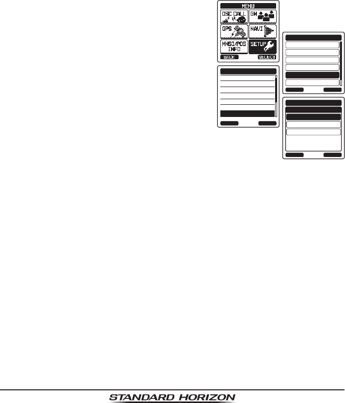
1. Press the MENU key to display “MENU”, then
select “SETUP” with the CH▲/CH▼/◄/►
key.
DSC SETUP
GM SETUP
BACK
SETUP
WAYPOINT SETUP
CH SETUP
GPS SETUP
ATIS SETUP
SELECT
GPS ON/OFF
POWER SAVE
DIRECTION
LOCATION FORMAT
TIME OFFSET
TIME AREA
TIME FORMAT
GPS SETUP
BACK SELECT
ON
ddd mm.mmm
BACK
GPS SETUP
ENTER
LOCATION FORMAT
°
ddd mm.mm
°
ddd mm.ss
°
2. Press the CH▲/CH▼ key to select “GPS
SETUP” menu.
3. Press the [SELECT] soft key, then select
“LOCATION FORMAT” with the CH▲/CH▼
key.
4. Press the [SELECT] soft key, then press
the CH▲/CH▼ key to select the desired
coordinate system. The location format can
be selected from “ddd’mm.ss”, “ddd’mm.mm”,
and “ddd’mm.mmm”.
5. Press the [ENTER] soft key to save the new setting.
6. Press the CLR key to return to radio operation.
15.4 TIME OFFSET
Sets the local time offset between UTC (Universal Time Coordinated) and local
time shown on the display. The offset is added or subtracted from the time
received from the GPS or chart plotter. Time is only displayed when a GPS or
chart plotter is connected.
Refer to section “6.4 CHANGING THE GPS TIME” for details.
Page 99
HX870
15.5 TIME AREA
This menu selection allows the radio to show UTC time or local time with the
offset.
Refer to section “6.5 CHANGING THE TIME LOCATION” for details.
15.6 TIME FORMAT
This menu selection allows the radio to show time in 12-hour or 24-hour format.
Refer to section “6.6 CHANGING THE TIME FORMAT” for details.
15.7 UNIT OF MEASURE
This section allows you to set the speed, distance and altitude units.
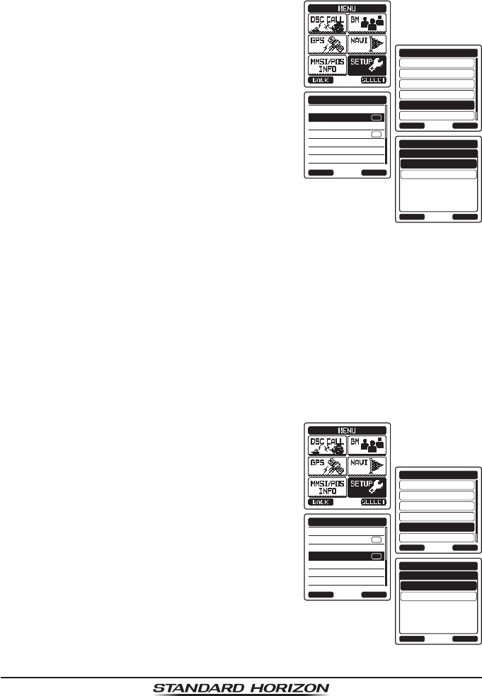
1. Press the MENU key to display “MENU”, then
select “SETUP” with the CH▲/CH▼/◄/►
key.
DSC SETUP
GM SETUP
BACK
SETUP
WAYPOINT SETUP
CH SETUP
GPS SETUP
ATIS SETUP
SELECT
POWER SAVE
DIRECTION
LOCATION FORMAT
TIME OFFSET
TIME AREA
TIME FORMAT
UNITS OF MEASURE
GPS SETUP
BACK SELECT
SPEED
BACK
GPS SETUP
DISTANCE
ALTITUDE
kts
nm
ft
SELECT
UNITS OF MEASURE
2. Press the CH▲/CH▼ key to select “GPS
SETUP” menu.
3. Press the [SELECT] soft key, then press
the CH▲/CH▼ key to select “UNIT OF
MEASURE”.
4. Press the [SELECT] soft key.
5. Press the CH▲/CH▼ key to select the item
you want to set.
6. Press the [SELECT] soft key.
7. Press the CH▲/CH▼ key to select the unit.
8. Press the [ENTER] soft key to store the new setting.
9. Press the CLR key to return to radio operation.
Page 100
HX870
15.8 PINNING
This selection is used to enable or disable position updates when the vessel
is not underway. The default setting is “OFF”.
1. Press the MENU key to display “MENU”, then
select “SETUP” with the CH▲/CH▼/◄/►
key.
DSC SETUP
GM SETUP
BACK
SETUP
WAYPOINT SETUP
CH SETUP
GPS SETUP
ATIS SETUP
SELECT
UNITS OF MEASURE
PINNING
POSITION INPUT
D-GPS
OUTPUT SENTENCES
LOGGER INTERVAL
LOG ERASE
GPS SETUP
BACK SELECT
ON
ON
OFF
BACK
GPS SETUP
ON
ENTER
PINNING
2. Press the CH▲/CH▼ key to select “GPS
SETUP” menu.
3. Press the [SELECT] soft key, then select
“PINNING” with the CH▲/CH▼ key.
4. Press the [SELECT] soft key.
5. Press the CH▲/CH▼ key to select “ON” or
“OFF”.
ON: When pinning is turned on, the HX870
will not update its position unless the
vessel travels over 10Ft.
OFF: When the vessel is underway or stopped, the HX870 continuously
updates its position (unless transmitting). This improves accuracy of
the position x.
6. Press the [ENTER] soft key to save the new setting.
7. Press the CLR key to return to radio operation.
15.9 SBAS (Satellite Based Augmentation System)
This selection enables or disables SBAS such as WAAS, EGNOS and MSAS
as some areas (Australia for example) can have problems with GPS reception
with SBAS enabled. The default setting is “ON”.
1. Press the MENU key to display “MENU”, then
select “SETUP” with the CH▲/CH▼/◄/►
key.
DSC SETUP
GM SETUP
BACK
SETUP
WAYPOINT SETUP
CH SETUP
GPS SETUP
ATIS SETUP
SELECT
UNITS OF MEASURE
PINNING
POSITION INPUT
D-GPS
OUTPUT SENTENCES
LOGGER INTERVAL
LOG ERASE
GPS SETUP
BACK SELECT
ON
ON
OFF
BACK
GPS SETUP
ON
ENTER
D-GPS
2. Press the CH▲/CH▼ key to select “GPS
SETUP” menu.
3. Press the [SELECT] soft key, then press the
CH▲/CH▼ key to select “D-GSP”.
4. Press the [SELECT] soft key.
5. Press the CH▲/CH▼ key to select “ON” or
“OFF”.
6. Press the [ENTER] soft key to store the new
setting.
7. Press the CLR key to return to radio opera-
tion.
Page 101
HX870
15.10 OUTPUT SENTENCES
This selection is used to setup the NMEA output sentences of the HX870.
By default, all the NMEA sentences are turned “OFF”.
1. Press the MENU key to display “MENU”, then
select “SETUP” with the CH▲/CH▼/◄/►
key.
DSC SETUP
GM SETUP
BACK
SETUP
WAYPOINT SETUP
CH SETUP
GPS SETUP
ATIS SETUP
SELECT
UNITS OF MEASURE
PINNING
POSITION INPUT
D-GPS
OUTPUT SENTENCES
LOGGER INTERVAL
LOG ERASE
GPS SETUP
BACK SELECT
ON
ON
GLL
BACK
GPS SETUP
GGA
GSA
GSV
RMC
ENTER
OUTPUT SENTENCES
ON
ON
2. Press the CH▲/CH▼ key to select “GPS
SETUP” menu.
3. Press the [SELECT] soft key, then select
“OUTPUT SENTENCES” with the CH▲/CH▼
key.
4. Press the [SELECT] soft key.
5. Press the CH▲/CH▼ key to select the
desired sentence type, then press the
[ENTER] soft key.
6. Press the CH▲/CH▼ key to select “ON” or
“OFF”.
7. Press the [ENTER] soft key to save the new
setting.
8. Repeat steps 5 through 7 to set the other sentences.
9. Press the CLR key to return to radio operation.
15.11 LOGGER INTERVAL
1. Press the MENU key to display “MENU”, then select “SETUP”
with the CH▲/CH▼/◄/► key.
UNITS OF MEASURE
PINNING
POSITION INPUT
D-GPS
OUTPUT SENTENCES
LOGGER INTERVAL
LOG ERASE
GPS SETUP
BACK SELECT
ON
ON
5sec
BACK
GPS SETUP
15sec
30sec
1min
5min
ENTER
LOGGER INTERVAL
2. Press the CH▲/CH▼ key to select “GPS SETUP” menu.
3. Press the [SELECT] soft key, then select “LOGGER INTER-
VAL” with the CH▲/CH▼ key.
4. Press the CH▲/CH▼ key to select the desired time and
press the [ENTER] soft key.
5. Press the CLR key to return to radio operation.
Log time for each logger interval setting
5 sec: Aprox. 8 hours
15 sec: Aprox. 25 hours
30 sec: Aprox. 50 hours
1 min: Aprox. 100 hours
5 min: Aprox. 500 hours
Page 102
HX870
15.12 LOG ERASE
1. Press the MENU key to display “MENU”, then select “SETUP”
with the CH▲/CH▼/◄/► key.
UNITS OF MEASURE
PINNING
POSITION INPUT
D-GPS
OUTPUT SENTENCES
LOGGER INTERVAL
LOG ERASE
GPS SETUP
BACK SELECT
ON
ON
CANCEL
BACK
GPS SETUP
OK
ENTER
LOG ERASE
2. Press the CH▲/CH▼ key to select “GPS SETUP” menu.
3. Press the [SELECT] soft key, then select “LOGGER ERASE”
with the CH▲/CH▼ key.
4. Select “CANCEL” or “OK” on the conrmation screen, then
press the [ENTER] soft key.
5. Press the CLR key to return to radio operation.
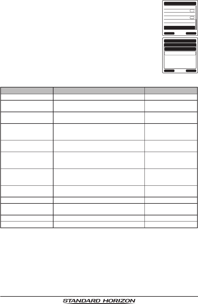
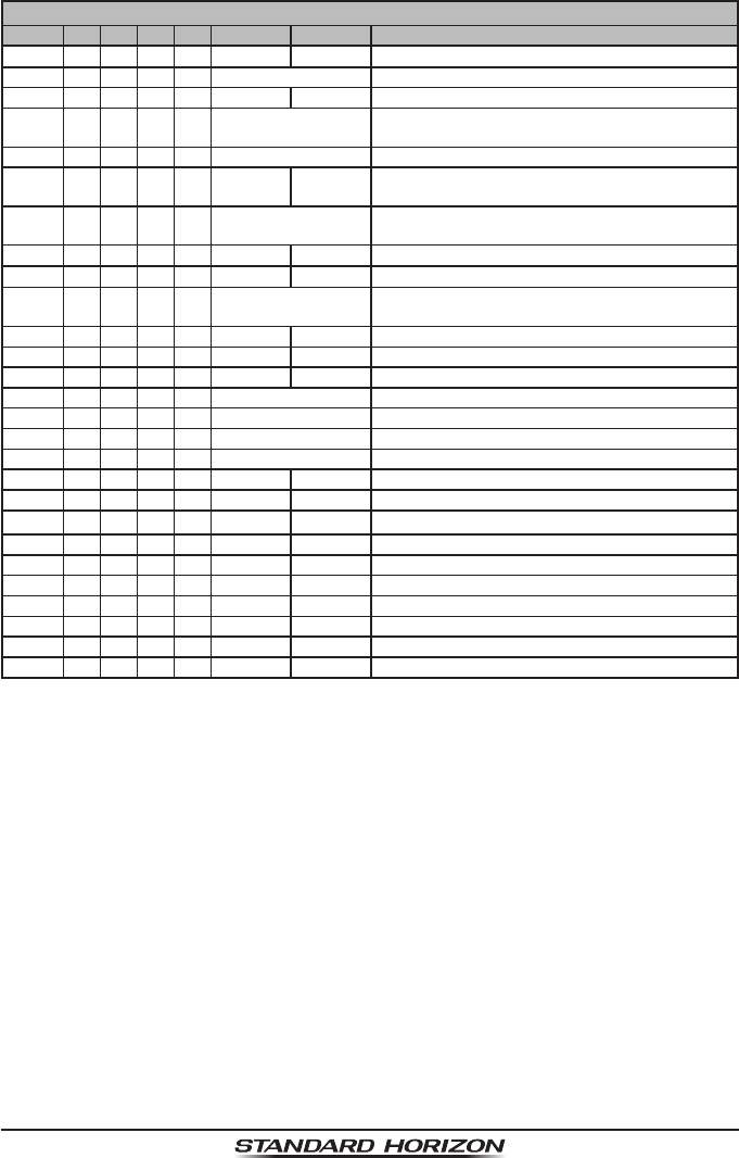
15.13 SUMMARY OF THE GPS SETUP
Item Description Default Value
UNIT POWER Switches on and off of the GPS unit power ON
POWER SAVE Selects the power save mode of the GPS
unit AUTO
LOCATION FORMAT Selects the coordinate system to be
displayed dd mm.mmm
TIME OFFSET Sets the offset time from the UTC (avail-
able only when “LOCAL” is selected in the
item “TIME AREA”)
00:00
TIME AREA Selects the time location to be displayed
from UTC or local UCT
TIME FORMAT Selects the time format from 12-hour or
24-hour display (xed to “24H” when “UTC”
is selected in the item “TIME AREA”)
24H
UNIT OF MEASURE Selects the unit when displaying speed,
distance, and altitude SPEED: kts
DISTANCE: nm
ALTITUDE: ft
PINNING Switches on and off of position updates for
vessel not underway OFF
D-GPS Switched on and off of use of SBAS ON
OUTPUT
SENTENCES Selects a sentence to be output to the
USB terminal OFF
LOGGER INTERVAL Selects the interval time of logging 1 min
LOG ERASE Erases the log data −

Page 103
HX870
16 MAINTENANCE
The inherent quality of the solid-state components used in this transceiver will
provide many years of continuous use. Taking the following precautions will
prevent damage to the transceiver.
• Never key the microphone unless an antenna or suitable dummy load is
connected to the transceiver.
• Ensure that the supply voltage to the transceiver does not exceed 8.5 VDC
or fall below 6 VDC.
• Use only STANDARD HORIZON-approved accessories and replacement
parts.
In the unlikely event of serious problems, please contact your Dealer or our
repair facility. Address and phone numbers for this facility, as well as warranty
information, are contained in section “18 WARRANTY”.
16.1 REPLACEMENT PARTS
Occasionally an owner needs a replacement mounting bracket or knob.
These can be ordered from our Parts Department by emailing
yaesuparts@yaesu.com or calling:
Marine Division of YAESU U.S.A.
6125 Phyllis Drive, Cypress, California 90630
Telephone (714) 827-7600
Commonly requested parts, and their part numbers are listed below.
• SBH-12 Charger Cradle: XXX
• CAT460 Antenna: AY139X001
• Belt Clip (CLIP-22): XXX
• MIC/SP Plastic Cap: RA108700B
• MIC/SP Cap O-Ring: RA046760A
• MIC/SP Rubber: RA1555900
Page 104
HX870
16.2 FACTORY SERVICE
In the unlikely event that the radio fails to perform or needs servicing, please
contact the following:
Standard Horizon
Attention Marine Repair Department
6125 Phyllis Drive, Cypress, California 90630, U.S.A.
Telephone (800) 366-4566
For repairs in Canada
Westcom Marine
488 East 62nd Avenue Vancouver BC V5X2G1
Telephone (604) 327-6280
An “RA” (Return Authorization) number is not necessary to send a product in
for service. Include a brief note describing the problem along with your name,
return address, phone number, and proof of purchase.
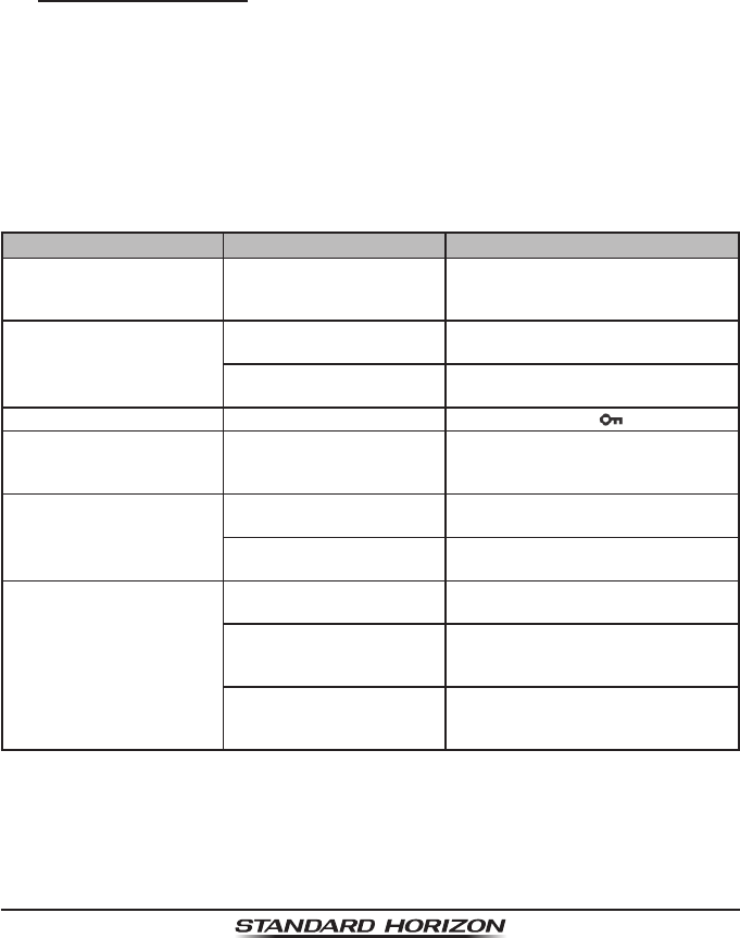
16.3 TROUBLESHOOTING CHART
SYMPTOM PROBABLE CAUSE REMEDY
The USA/INTL/CAN
modes do not function. Proper operation not
followed. Specify the item number from
“SETUP MENU” – “CH SETUP” – “CH
GROUP”.
Cannot output sound by
pressing and holding the
SQL key.
Low battery. Charge battery. Refer to section 6
of this manual.
Audio volume level is too
low. Press the VOL+ key until back-
ground noise outputs.
Keys do not function. Key Lock is “on”. Press and hold the key to unlock.
Cannot transmit a DSC
Call. MMSI number is not
programmed. Program the MMSI number. Refer
to section “9.2.2 Programming
the MMSI”.
Cannot x the GPS satel-
lites. Internal GPS receiver is
“off”. Internal GPS receiver is “on”. Refer
to “14.1 GPS ON/OFF”.
Poor location for GPS
satellite reception. Move to a less obstructed position.
Indicator does not light
when charging a battery. Defective battery SBR-
13LI.Contact Standard Horizon dealer.
The transceiver is not set
onto the SBH-12 Charger
Cradle properly.
Set the transceiver onto the SBH-12
Charger Cradle properly.
Power is not supplied
to the SBH-12 Charger
Cradle.
Connect SAD-11B or E-DC-19A to
the SBH-12 Charger Cradle for AC/
DC power supplies.

Page 105
HX870
17 CHANNEL ASSIGNMENTS
Tables on the following columns list the VHF Marine Channel assignments for
U.S.A. and International use. Below are listed some data about the charts.
1. VTS. Where indicated, these channels are part of the U.S. Coast Guard’s
Vessel Trafc System.
2. Alpha channel numbers, that is, channel numbers followed by the letter A
(such as Channel 07A) are simplex channels on the U.S.A. or Canadian
channel assignments whose counterparts in the International assignments
are duplex channels. International channels do not use “alpha” numbers. If
you call the Coast Guard on Channel 16, they will sometimes ask you to “go
to channel 22 Alpha”. This is a channel assigned to U.S.A, and Canadian
Coast Guards for handling distress and other calls. If your radio is set for
International operation you will go to Channel 22 instead of 22A, and will
not be able to communicate with the Coast Guard. To use Channel 22A,
your radio must be set for USA or Canada operation, usually by a U/I/C
(USA/International/Canada) control or combination of controls. Channel
22 (without an “A”) is an International duplex channel for port operations.
Some radios indicate an “A” adjacent to the alpha channels on the display;
on others “alpha” is not indicated but the proper channel is selected based
on the U/I/C setting.
3. Bridge-to-Bridge channels (for example, Channel 13) are for use by bridge
operators on inter-coastal waterways and rivers. It is also used by marine
vessels in the vicinity of these bridges for navigation and for communicating
with the bridge operators. Note that a limit of 1 Watt is specied for these
channels.
4. The S/D column on the chart indicates either S (simplex) or D (duplex).
Simplex means transmitting and receiving on the same frequency. Only
one party at a time can talk, unlike a telephone. Be sure to say “over” and
release your microphone push-to-talk switch at the end of each transmis-
sion. Duplex operation involves the use of one frequency for transmitting
and a separate frequency for receiving. On channels specied as duplex on
the charts, correct mode of operation is established automatically by your
radio when you select a channel; you cannot change the mode. And you
still must release the push-to-talk switch after each transmission in order
to listen to the radio.
5. Channels normally used by recreational boaters are those that include the
term “non-commercial” in the Channel Use column of the chart. Some
of these are shared with other users and some are used only in certain
geographic regions.

Page 106
HX870
6. Marine vessels equipped with VHF radios are required to monitor Channel
16.
7. 156.050 MHz and 156.175 MHz are available for port operations and
commercial communications purposes when used only within the U.S. Coast
Guard designated Vessel Trafc Services (VTS) area of New Orleans, on
the lower Mississippi River from the various pass entrances in the Gulf of
Mexico to Devil’s Swamp Light at River Mile 242.4 above head of passes
near Baton Rouge.
8. 156.250 MHz is available for port operations communications use only
within the U.S. Coast Guard designated VTS radio protection areas of New
Orleans and Houston described in Sec. 80.383. 156.250 MHz is available
for intership port operations communications used only within the area of
Los Angeles and Long Beach harbors, within a 25- nautical mile radius of
Point Fermin, California.
9. 156.550 MHz, 156.600 MHz and 156.700 MHz are available in the U.S.
Coast Guard designated port areas only for VTS communications and
in the Great Lakes available primarily for communications relating to the
movement of ships in sectors designated by the St. Lawrence Seaway
Development Corporation or the U.S. Coast Guard. The use of these
frequencies outside VTS and ship movement sector protected areas is
permitted provided they cause no interference to VTS and ship movement
communications in their respective designated sectors.
10. Use of 156.875 MHz is limited to communications with pilots regarding the
movement and docking of ships. Normal output power must not exceed 1
watt. 5: 156.375 MHz and 156.650 MHz are available primarily for intership
navigational communications. These frequencies are available between
coast and ship on a secondary basis when used on or in the vicinity of locks
or drawbridges. Normal output power must not exceed 1 watt. Maximum
output power must not exceed 10 watts for coast stations or 25 watts for
ship stations.
11. On the Great Lakes, in addition to bridge-to-bridge communications, 156.650
MHz is available for vessel control purposes in established vessel trafc
systems. 156.650 MHz is not available for use in the Mississippi River
from South Pass Lighted Whistle Buoy “2” and Southwest Pass entrance
Mid-channel Lighted Whistle Buoy to mile 242.4 above Head of Passes
near Baton Rouge. Additionally it is not available for use in the Mississippi
River-Gulf Outlet, the Mississippi River-Gulf Outlet Canal, and the Inner
Harbor Navigational Canal, except to aid the transition from these areas.
12. Use of 156.375 MHz is available for navigational communications only in
the Mississippi River from South Pass Lighted Whistle Buoy “2” and South-

Page 107
HX870
west Pass entrance Mid channel Lighted Whistle Buoy to mile 242.4 above
head of Passes near Baton Rouge, and in addition over the full length of
the Mississippi River-Gulf Outlet Canal from entrance to its junction with the
Inner Harbor Navigation Canal, and over the full length of the Inner Harbor
Navigation Canal from its junction with the Mississippi River to its entry to
Lake Pontchartrain at the New Seabrook vehicular bridge.
13. Within 120 km (75 miles) of the United States/Canada border, in the area of
the Puget Sound and the Strait of Juan de Fuca and its approaches, 157.425
MHz is half of the duplex pair designated as Channel 88. In this area, Chan-
nel 88 is available to ship stations for communications with public coast
stations only. More than 120 km (75 miles) from the United States/Canada
border in the area of the Puget Sound and the Strait of Juan de Fuca, its
approaches, the Great Lakes, and the St. Lawrence Seaway, 157.425
MHz is available for intership and commercial communications. Outside
Puget Sound area and its approaches and the Great Lakes, 157.425 MHz
is also available for communications between commercial shing vessels
and associated aircraft while engaged in commercial shing activities.
14. When the frequency 156.850 MHz is authorized, it may be used addition-
ally for search and rescue training exercises conducted by state or local
governments.
15. The frequency 156.850 MHz is additionally available to coast stations on
the Great Lakes for transmission of scheduled Coded Marine Weather Fore-
casts (MAFOR), Great Lakes Weather Broadcast (LAWEB) and scheduled
Notices to Mariners or Bulletins. F3C and J3C emissions are permitted.
Coast Stations on the Great Lakes must cease weather broadcasts which
cause interference to stations operating on 156.800 MHz until the interfer-
ence problem is resolved.
16. The frequency 157.100 MHz is authorized for search and rescue training
exercises by state or local government in conjunction with U.S. Coast Guard
stations. Prior U.S. Coast Guard approval is required. Use must cease
immediately on U.S. Coast Guard request.
17. The duplex pair for channel 20 (157.000/161.600 MHz) may be used for
ship to coast station communications.
18. Available for assignment to coast stations, the use of which is in accord
with an agreed program, for the broadcast of information to ship stations
concerning the environment.
Page 108
HX870
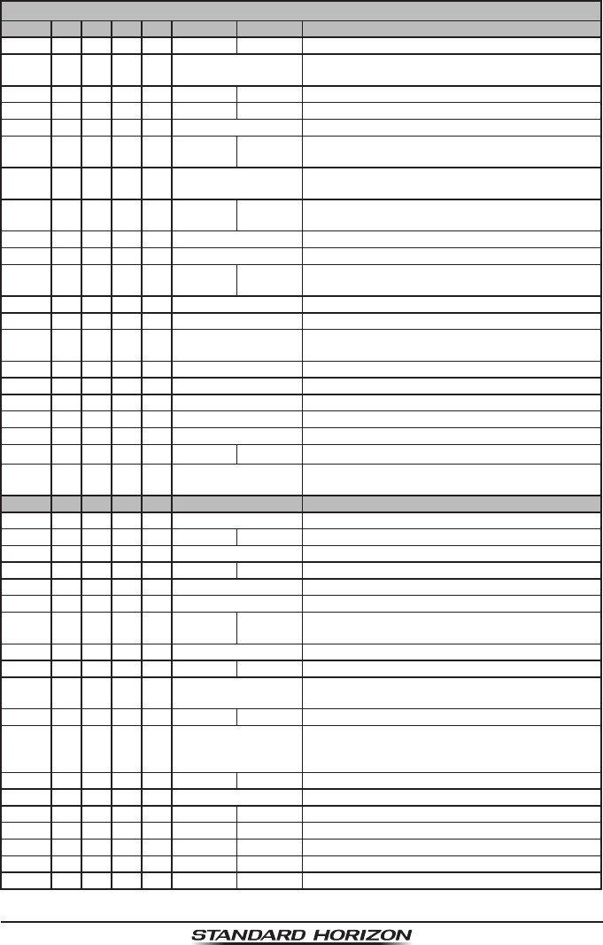
VHF MARINE CHANNEL CHART
CH U C I S/D TX RX CHANNEL USE
01 X X D 156.050 160.650 Public Correspondence (Marine Operator)
01A X S 156.050 Port Operation and Commercial.
VTS in selected areas
02 X X D 156.100 160.700 Public Correspondence (Marine Operator)
03 X X D 156.150 160.750 Public Correspondence (Marine Operator)
03A X S 156.150 U.S. Government Only, Coast Guard
04 X D 156.200 160.800 Public Correspondence (Marine Operator),
Port operation, ship movement
04A X S 156.200 Pacic coast: Coast Guard, East Coast:
Commercial shing
05 X D 156.250 160.850 Public Correspondence (Marine Operator),
Port operation, ship movement
05A X X S 156.250 Port operation. VTS in Seattle
06 X X X S 156.300 Inter-ship Safety
07 X D 156.350 160.950 Public Correspondence (Marine Operator),
Port operation, ship movement
07A X X S 156.350 Commercial
08 X X X S 156.400 Commercial (Inter-ship only)
09 X X X S 156.450 Boater Calling channel, Commercial &
Non-commercial (Recreational)
10 X X X S 156.500 Commercial
11 X X X S 156.550 Commercial. VTS in selected areas
12 X X X S 156.600 Port operation. VTS in selected areas
13 X X X S 156.650 Inter-ship Navigation Safety (Bridge-to-bridge)
14 X X X S 156.700 Port operation. VTS in selected areas
15 X S - - - 156.750 Environmental (Receive only)
15 X X S 156.750 Commercial, non-commercial,
ship movement (1 W)
16 X X X S 156.800 International Distress, Safety and Calling
17 X X X S 156.850 State Controlled (1 W)
18 X D 156.900 161.500 Port operation, ship movement
18A X X S 156.900 Commercial
19 X D 156.950 161.550 Port operation, ship movement
19A X S 156.950 US: Commercial
19A X S 156.950 Coast Guard
20 X X X D 157.000 161.600 Canadian Coast Guard Only,
International: port operations and shipment
20A X S 157.000 Port operation
21 X D 157.050 161.650 Port operation, ship movement
21A X X S 157.050 U.S. Government Only,
Canadian Coast Guard
22 X D 157.100 161.700 Port operation, ship movement
22A X X S 157.100 US and Canadian Coast Guard Liaison and ari-
time Safety Information Broadcasts announced
on channel 16
23 X X D 157.150 161.750 Public Correspondence (Marine Operator)
23A X S 157.150 U.S. Government Only
24 X X X D 157.200 161.800 Public Correspondence (Marine Operator)
25 X X X D 157.250 161.850 Public Correspondence (Marine Operator)
26 X X X D 157.300 161.900 Public Correspondence (Marine Operator)
27 X X X D 157.350 161.950 Public Correspondence (Marine Operator)
28 X X X D 157.400 162.000 Public Correspondence (Marine Operator)

Page 109
HX870
VHF MARINE CHANNEL CHART
CH U C I S/D TX RX CHANNEL USE
60 X X D 156.025 160.625 Public Correspondence (Marine Operator)
61 X D 156.075 160.675 Public Correspondence (Marine Operator),
Port operation, ship movement
61A X X S 156.075 Public Coast: Coast Guard;
East Coast: commercial shing only
62 X D 156.125 160.725 Public Correspondence (Marine Operator),
Port operation, ship movement
62A X S 156.125 Public Coast: Coast Guard;
East Coast: commercial shing onl
63 X D 156.175 160.775 Public Correspondence (Marine Operator),
Port operation, ship movement
63A X X S 156.175 Port Operation and Commercial.
VTS in selected areas
64 X X D 156.225 160.825 Public Correspondence (Marine Operator),
Port operation, ship movement
64A X X S 156.225 Public Correspondence (Marine Operator),
Port operation, ship movement
65 X D 156.275 160.875 Public Correspondence (Marine Operator),
Port operation, ship movement
65A X X S 156.275 Port Operations
66 X D 156.325 160.925 Public Correspondence (Marine Operator),
Port operation, ship movement
66A X X S 156.325 Port Operations
67 X X X S 156.375 US: Commercial.
Used for Bridge-to-bridge communi-cations in
lower Mississippi River. Inter-ship only,
Canada: Commercial shing, S&R
68 X X X S 156.425 Non-commercial (Recreational)
69 X X X S 156.475 US: Non-commercial (Recreational),
Canada: Commercial shing only,
International: Inter-ship, Port operations and
Ship movement
70 X X X S 156.525 Digital selective calling
(voice communications not allowed)
71 X X X S 156.575 US, Canada: Non-commercial (Recreational),
International: Port operations and Ship move-
ment
72 X X X S 156.625 Non-commercial (Inter-ship only)
73 X X X S 156.675 US: Port Operations,
Canada: Commercial shing only,
International: Inter-ship, Port operations and
Ship movement
74 X X X S 156.725 US: Port Operations,
Canada: Commercial shing only,
International: Inter-ship, Port operations and
Ship movement
75 X X X S 156.775 Port Operations (Inter-ship only) (1W)
76 X X X S 156.825 Port Operations (Inter-ship only) (1W)
77 X X S 156.875 Port Operations (Inter-ship only) (1W)
77 X S 156.875 Port Operations (Inter-ship only)
78 X D 156.925 161.525 Public Correspondence (Marine Operator),
Port operation, ship-movement
78A X X S 156.925 Non-commercial (Recreational)
79 X D 156.975 161.575 Port operation and Ship movement
79A X X S 156.975 Commercial
Page 110
HX870
NOTE: Simplex channels, 03A, 21A, 23A, 61A, 64A, 81A, 82A and 83A CANNOT be lawfully
used by the general public in U.S.A. waters.
VHF MARINE CHANNEL CHART
CH U C I S/D TX RX CHANNEL USE
80 X D 157.025 161.625 Port operation, ship movement
80A X X S 157.025 Commercial
81 X D 157.075 161.675 Port operation, ship movement
81A X S 157.075 U.S. Government Only -
Environmental protection operations
81A X S 157.075 Canadian Coast Guard Only
82 X D 157.125 161.725 Public Correspondence (Marine Operator),
Port operation, ship movement
82A X X S 157.125 U.S. Government Only,
Canadian Coast Guard Only
83 X D 157.175 161.775 Canadian Coast Guard Only
83 X D 157.175 161.775 Public Correspondence (Marine Operator)
83A X X S 157.175 U.S. Government Only,
Canadian Coast Guard Only
84 X X X D 157.225 161.825 Public Correspondence (Marine Operator)
85 X X X D 157.275 161.875 Public Correspondence (Marine Operator)
86 X X X D 157.325 161.925 Public Correspondence (Marine Operator)
87 X X S 157.375 Port operation, ship movement
87A X S 157.375 Public Correspondence (Marine Operator)
88 X X S 157.425 Port operation, ship movement
88A X S 157.425 Commercial, Inter-ship Only
WX01 X X X D - - - 162.550 Weather (receive only)
WX02 X X X D - - - 162.400 Weather (receive only)
WX03 X X X D - - - 162.475 Weather (receive only)
WX04 X X X D - - - 162.425 Weather (receive only)
WX05 X X X D - - - 162.450 Weather (receive only)
WX06 X X X D - - - 162.500 Weather (receive only)
WX07 X X X D - - - 162.525 Weather (receive only)
WX08 X X X D - - - 161.650 Weather (receive only)
WX09 X X X D - - - 161.775 Weather (receive only)
WX10 X X X D - - - 163.275 Weather (receive only)

Page 111
HX870
18 WARRANTY
Marine Products Limited Warranty
PLEASE NOTE
The following “Limited Warranty” is for valid for products that have been
purchased in the United States and Canada. For limited Warranty details
outside the United States, contact the dealer in your country.
STANDARD HORIZON (a division of YAESU U.S.A.) warrants, to the original
purchaser only, each new Marine Communications Product (“Product”) manu-
factured and/or supplied by STANDARD HORIZON against defects in materials
and workmanship under normal use and service for a period of time from the
date of purchase as follows:
Fixed Mount and Portable Transceivers
1 year - if purchased before 01/01/91
3 years - if purchased between 01/01/91 and 01/01/94
3 years Waterproof - if purchased after 01/01/94
Loud hailers
1 year - if purchased before 01/01/91
3 years - if purchased after 01/01/91
Associated Chargers
1 year - if purchased before 01/01/91
3 years - if purchased after 01/01/91
Associated Batteries - 1 year. Note: Batteries will be deemed deective only
if storage capacity drops below 80% of rated capacity or if leakage develops.
Associated Accessories - 1 year. Includes: Microphones/Handsets, External
Speakers, Antennas, Carrying Accessories, Power Supplies, and Signaling
Boards.
To receive warranty service, the purchaser must deliver the Product, transporta-
tion and insurance prepaid, to STANDARD HORIZON, Attention Marine repairs
6125 Phyllis Drive, Cypress, California 90630, U.S.A. Include proof of purchase
indicating model. serial number, and date of purchase. STANDARD HORIZON
will return the Product to the purchaser freight prepaid. Products purchased
prior to January 1, 1991 will bear the STANDARD HORIZON warranty terms
in effect prior to that date.
In the event of a defect, malfunction or failure of the Product during the warranty
period, STANDARD HORIZON’s liability for any breach of contract or any
breach of express or implied warranties in connection with the sale of Products
shall be limited solely to repair or replacement, at its option, of the Product or

Page 112
HX870
part(s) therein which, upon examination by STANDARD HORIZON, appear to
be defective or not up to factory specications. STANDARD HORIZON may, at
its option, repair or replace parts or subassemblies with new or reconditioned
parts and subassemblies. Parts thus repaired or replaced are warranted for
the balance of the original applicable warranty.
STANDARD HORIZON will not warrant installation, maintenance or service of
the Products. In all instances, STANDARD HORIZON’s liability for damages
shall not exceed the purchase price of the defective Product.
This warranty only extends to Products sold within the 50 States of the United
States of America and the District of Columbia.
STANDARD HORIZON will pay all labor to repair the product and replace-
ment parts charges incurred in providing the warranty service except where
purchaser abuse or other qualifying exceptions exist. The purchaser must pay
any transportation expenses incurred in returning the Product to STANDARD
HORIZON for service.
This limited warranty does not extend to any Product which has been subjected
to misuse, neglect, accident, incorrect wiring by anyone other than STANDARD
HORIZON, improper installation, or subjected to use in violation of instructions
furnished by STANDARD HORIZON, nor does this warranty extend to Products
on which the serial number has been removed, defaced, or changed. STAN-
DARD HORIZON cannot be responsible in any way for ancillary equipment not
furnished by STANDARD HORIZON which is attached to or used in connection
with STANDARD HORIZON’s Products, or for the operation of the Product with
any ancillary equipment, and all such equipment is expressly excluded from
this warranty. STANDARD HORIZON disclaims liability for range, coverage, or
operation of the Product and ancillary equipment as a whole under this warranty.
STANDARD HORIZON reserves the right to make changes or improvements
in Products, during subsequent production, without incurring the obligation to
install such changes or improvements on previously manufactured Products.
The implied warranties which the law imposes on the sale of this Product are
expressly LIMITED, in duration, to the time period specied above. STANDARD
HORIZON shall not be liable under any circumstances for consequential damag-
es resulting from the use and operation of this Product, or from the breach of this
LIMITED WARRANTY, any implied warranties, or any contract with STANDARD
HORIZON. IN CONNECTION WITH THE SALE OF ITS PRODUCTS, STAN-
DARD HORIZON MAKES NO WARRANTIES, EXPRESS OR IMPLIED AS TO
THE MERCHANTABILITY OR FITNESS FOR A PARTICULAR PURPOSE OR
OTHERWISE, EXCEPT AS EXPRESSLY SET FORTH HEREIN.

Page 113
HX870
Some states do not allow the exclusion or limitation of incidental or consequen-
tial damages, or limitation on how long an implied warranty lasts, so the above
limitations or exclusions may not apply. This warranty gives specic legal rights,
and there may be other rights which may vary from state to state.
ONLY PRODUCTS SOLD ON OR AFTER JANUARY 1, 1991 ARE COVERED
UNDER THE TERMS OF THIS LIMITED WARRANTY.

Page 114
HX870
ON-LINE WARRANTY REGISTRATION
THANK YOU for buying STANDARD HORIZON (a division of YAESU
U.S.A.) products! We are condent your new radio will serve your
needs for many years!
Please visit www.standardhorizon.com to register your Marine
VHF. It should be noted that visiting the website from time to time may
be benecial to you, as new products are released they will appear
on the STANDARD HORIZON website. Also a statement regarding
product support should be added to the manual.
Product Support Inquiries
If you have any questions or comments regarding the use of the radio,
you can visit the STANDARD HORIZON website to send an E-Mail
or contact the Product Support team at (714) 827-7600 ext 6300 M-F
8:00-5:00 PST.
In addition to the warranty, STANDARD HORIZON includes a lifetime
“at rate” and “customer loyalty” programs to provide service after the
warranty period has expired. If you wish to obtain the at rate price
for out-of-warranty repair, you must include the information on the
Owner’s Record with the unit when you return it to your Dealer or to
STANDARD HORIZON.
Lifetime Flat Rate Service Program: For the original Owner only, for
the lifetime of the unit, STANDARD HORIZON will repair the unit to
original specications.
Note: The at rate amount is payable by the Owner only if STANDARD
HORIZON or the STANDARD HORIZON Dealer determines that a
repair is needed. After the repair, a 90-day warranty will be in effect
from the date of return of the unit to the Owner.
This service program is not available for equipment which has failed as
a result of neglect, accident, breakage, misuse, improper installation
or modication, or water damage (depending on the product).
Page 115
HX870
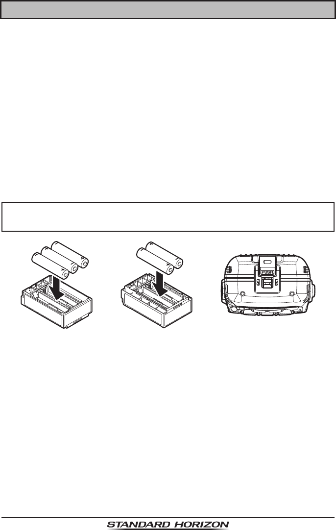
19 INSTALLATION OF THE SBT-13
The SBT-13 is a battery case that holds ve “AAA” size Alkaline batteries and
is used with the HX870 transceiver. The Alkaline batteries can be used for
receiving and transmission in an emergency, and battery life will be shortened
dramatically.
1. Slide the ve “AAA” size Alkaline batteries into the SBT-13 with the Negative
(−) side of the batteries touching the spring connections inside the SBT-13.
2. Slide the battery cover lock switch to the “UNLOCK” position, then press
“PUSH” to open the battery cover.
3. Install the SBT-13 into the battery rest on the bottom of the transceiver
pushing it to the battery contacts until it clicks.
4. Attach the battery cover, then slide the battery cover lock switch to the
“LOCK” position.
NOTE
When the SBT-13 Alkaline Battery Case is used, the HX870 transmit
output is xed to 1 W.

Page 116
HX870
20 SPECIFICATIONS
Performance specications are nominal, unless otherwise indicated, and are
subject to change without notice. Measured in accordance with TIA/EIA-603.
20.1 GENERAL
Frequency Range ........................................ TX: 156.025 MHz - 157.425 MHz
RX: 156.050 MHz - 163.275 MHz
Channel Spacing ...................................................................................25 kHz
Frequency Stability ...................±3 ppm (−4 °F to +140 °F [−20 °C to +60 °C])
Emission Type ....................................16K0G3E for Voice, 16K0G2B for DSC
Antenna Impedance ................................................................................. 50 Ω
Supply Voltage..........................7.4V DC, Negative Ground (Battery Terminal)
Current Consumption .......................................................... 330 mA (Receive)
100 mA (Standby, GPS On)
60 mA (Standby, GPS Off)
1.6 A / 1.0 A / 0.7 A
(TX: 6W / 2W / 1W)
Operating Temperature ............................−4 °F to +140 °F (−20 °C to +60 °C)
DSC Individual Directory ........................................................... 100 Memories
DSC Group Directory................................................................... 20 Memories
DSC Format ............................................................................ ITU-R M.493-13
NMEA Output............................DSC, DSE, GLL, GGA, GSA, GSV, and RMC
Case Size (W x H x D) ........2.44” x 5.43” x 1.69” (62 mm x 138 mm x 43 mm)
(w/o knob & antenna)
Weight ....................................................................................11.36 oz (322 g)
w/ SBR-13LI, hand strap, belt clip & antenna
20.2 TRANSMITTER
RF Power Output .................. 6 W (HI) / 2 W (MIDDLE) / 1 W (LOW) (@7.4 V)
Modulation Type ................................................................Variable Reactance
Maximum Deviation ...............................................................................±5 kHz
Spurious Emission ................................................................... −75 dBc typical
Microphone Impedance ............................................................................ 2 kΩ

Page 117
HX870
20.3 RECEIVER (for Voice and DSC)
Circuit Type ............................................Double-Conversion Superheterodyne
Intermediate Frequencies ......................................... for Voice 1st: 38.85 MHz
2nd: 450 kHz
for DSC 1st: 30.4 MHz
2nd: 450 kHz
Sensitivity ..................................................for Voice 0.25 μV for 12 dB SINAD
for DSC 0.5 μV for 12 dB SINAD
Adjacent Channel Selectivity ....................................................... 70 dB typical
Intermodulation ............................................................................ 70 dB typical
Hum & Noise Ratio ..................................................................................40 dB
Selectivity .................................................... 12 kHz / 25 kHz (−6 dB / −60 dB)
AF Output (Internal SP) .................... 700 mW @16 Ω for 10 % THD (@7.4 V)
20.4 GPS
Receiver Channels ........................................................................66 channels
Sensitivity ........................................................................Less than −147 dBm
Time to First Fix ..................................................... 1 min typical (@Cold Start)
5 sec typical (@Hot Start)
Geodetic Datum................................................................................... WGS84
20.5 NMEA OUTPUT
NMEA 0183 Output Sentence (9600 baud) ................. DSC, DSE, GGA, GLL,
RMC, GSA & GSV

Page 118
HX870
21 FCC RADIO LICENSE INFORMATION
Standard Horizon radios comply with the Federal Communication Commission
(FCC) requirements that regulate the Maritime Radio Service.
21.1 STATION LICENSE
An FCC ship station license is no longer required for any vessel traveling in
U.S. waters (except Hawaii) which is under 20 meters in length. However, any
vessel required to carry a marine radio on an international voyage, carrying
a HF single side band radiotelephone or marine satellite terminal is required
to have a ship station license. FCC license forms, including applications for
ship (605) and land station licenses can be downloaded via the Internet at
http://www.fcc.gov/Forms/Form605/605.html. To obtain a form from the FCC,
call (888) 225-5322.
21.2 RADIO CALL SIGN
Currently the FCC does not require recreational boaters to have a Ship Radio
Station License. The USCG recommends the boats registration number and
the state to be used when calling another vessel.
21.3 CANADIAN SHIP STATION LICENSING
You may need a license when traveling in Canada. If you do need a license
contact their nearest eld ofce or regional ofce or write:
Industry Canada
Radio Regulatory Branch
Attn: DOSP
300 Slater Street
Ottawa, Ontario
Canada, KIA 0C8
21.4 FCC / INDUSTRY CANADA INFORMATION
The following data pertaining to the transceiver is necessary to ll out the
license application.
Type Acceptance ..........................................................................FCC Part 80
Output Power.......................1 Watt (low), 2 Watts (middle) and 6 Watts (high)
Emission ..........................................................................16K0G3E, 16K0G2B
Frequency Range ......................................................156.025 to 163.275 MHz
FCC Type Number ..................................................................... K6630573X30
Industry Canada Type Approval ............................................ 511B-30573X30

Page 119
HX870
22 RF EXPOSURE SAFETY STATEMENT
SAFETY INFORMATION
Your wireless handheld portable transceiver contains a low power transmit-
ter. When the Push-to-Talk (PTT) button is pushed, the transceiver sends out
radio frequency (RF) signals. In August 1996, the Federal Communications
Commission adopted RF exposure guidelines with safety levels for hand-held
wireless devices.
This device is authorized to operate at a duty factor not to exceed 50 % (this
corresponds to 50% transmission time and 50 % reception time).
WARNING: To maintain compliance with the FCC’s RF exposure guidelines,
this transmitter and its antenna must maintain a separation distance of at least
1 inch (2.5 centimeters) from your face. Speak in a normal voice, with the
antenna pointed up and away from the face at the required separation distance.
If you use a headset accessory for this radio, with the radio worn on your body,
use only the Yaesu belt clip for this transceiver, and ensure that the antenna is
at least 1 inch (2.5 centimeters) from your body when transmitting.
Use only the supplied antenna. Unauthorized antennas, modications, or
attachments could damage the transmitter, and may violate FCC regulations.
CONSIGNES DE SECURITE
Votre émetteur-récepteur portatif sans l contient un émetteur à faible puissance.
Lorsque vous appuyez sur le bouton Push-to-Talk (PTT), l’émetteur-récepteur
émet des signaux de radiofréquence (RF). En août 1996, la FCC (Commission
Fédérale des Communications) a adopté des directives relatives à l’exposition
aux RF avec des niveaux de sécurité pour les appareils sans ls portatifs.
Le fonctionnement de cet appareil est autorisé à un facteur d’utilisation ne
dépassant pas 50 % (correspondant à 50% de la durée de transmission et
50% de la durée de réception).
AVERTISSEMENT: Pour assurer la conformité avec les directives d’exposition
RF de la FCC, cet émetteur-récepteur et son antenne doivent être maintenus
à une distance minimum d’un pouce (2,5 centimètre) de votre visage. Parlez
avec une voix normale, avec l’antenne dirigée vers le haut et éloignée du
visage, à la distance requise.
Si vous utilisez un casque pour cette radio, et que vous portez la radio sur vous,
utilisez exclusivement le clip de ceinture Yaesu pour cet émetteur-récepteur,
et assurez-vous que l’antenne se trouve à une distance minimum d’un pouce
(2,5 centimètres) de votre corps pendant l’émission.
Utilisez exclusivement l’antenne fournie. Les antennes, les modications ou
les accessoires non autorisés peuvent endommager l’émetteur-récepteur et
enfreindre les réglementations FCC.

Page 120
HX870
23 FCC NOTICE
NOTICE
Unauthorized changes or modications to this equipment may void
compliance with FCC Rules. Any change or modication must be
approved in writing by STANDARD HORIZON.
NOTICE
This equipment has been tested and found to comply with the limits for
a Class B digital device, pursuant to Part 15 of the FCC Rules. These
limits are designed to provide reasonable protection against harmful
interference in a residential installation. This equipment generates,
uses and can radiate radio frequency energy and, if not installed and
used in accordance with the instructions, may cause harmful interfer-
ence to radio communications. However, there is no guarantee that
interference will not occur in a particular installation. If this equipment
does cause harmful interference to radio or television reception, which
can be determined by turning the equipment off and on, the user is
encouraged to try to correct the interference by one or more of the
following measures:
Reorient or relocate the receiving antenna.
Increase the separation between the equipment and receiver.
Connect the equipment into an outlet on a circuit different from that
to which the receiver is connected.
Consult the dealer or an experienced radio/TV technician for help.

Page 121
HX870
THIS DEVICE COMPLIES WITH PART 15 OF THE FCC RULES. OPERATION IS
SUBJECT TO THE FOLLOWING TWO CONDITIONS: (1) THIS DEVICE MAY NOT
CAUSE HARMFUL INTERFERENCE, AND (2) THIS DEVICE MUST ACCEPT ANY
INTERFERENCE RECEIVED, INCLUDING INTERFERENCE THAT MAY CAUSE
UNDESIRED OPERATION.
Changes or modications to this device not expressly approved by YAESU U.S.A.
could void the User’s authorization to operate this device.
This device complies with Industry Canada license-exempt RSS standard(s).
Operation is subject to the following two conditions: (1) this device may not cause
interference, and (2) this device must accept any interference, including interference
that may cause undesired operation of the device.
Le présent appareil est conforme aux CNR d’Industrie Canada applicables aux
appareils radio exempts de licence. L’exploitation est autorisée aux deux conditions
suivantes : (1) l’appareil ne doit pas produire de brouillage, et (2) l’utilisateur de
l’appareil doit accepter tout brouillage radioélectrique subi, même si le brouillage
est susceptible d’en compromettre le fonctionnement.
Under Industry Canada regulations, this radio transmitter may only operate using
an antenna of a type and maximum (or lesser) gain approved for the transmitter by
Industry Canada. To reduce potential radio interference to other users, the antenna
type and its gain should be so chosen that the equivalent isotropically radiated power
(e.i.r.p.) is not more than that necessary for successful communication.
Conformément à la réglementation d’Industrie Canada, le présent émetteur radio
peut fonctionner avec une antenne d’un type et d’un gain maximal (ou inférieur)
approuvé pour l’émetteur par Industrie Canada. Dans le but de réduire les risques
de brouillage radioélectrique à l’intention des autres utilisateurs, il faut choisir le
type d’antenne et son gain de sorte que la puissance isotrope rayonnée quivalente
(p.i.r.e.) ne dépassepas l’intensité nécessaire à l’établissement d’une communication
satisfaisante.
This radio transmitter (identify the device by certication number, or model number
if Category II) has been approved by Industry Canada to operate with the antenna
types listed below with the maximum permissible gain and required antenna
impedance for each antenna type indicated. Antenna types not included in this list,
having a gain greater than the maximum gain indicated for that type, are strictly
prohibited for use with this device.
Le présent émetteur radio (identier le dispositif par son numéro de certication ou
son numéro de modèle s’il fait partie du matériel de catégorie I) a été approuvé par
Industrie Canada pour fonctionner avec les types d’antenne énumérés ci-dessous
et ayant un gain admissible maximal et l’impédance requise pour chaque type
d’antenne. Les types d’antenne non inclus dans cette liste, ou dont le gain est
supérieur au gain maximal indiqué, sont strictement interdits pour l’exploitation de
l’émetteur. l’établissement d’une communication satisfaisante.
Page 122
HX870
Copyright 2014
YAESU MUSEN CO., LTD.
All rights reserved.
No portion of this manual
may be reproduced
without the permission of
YAESU MUSEN CO., LTD.
Printed in China
YAESU U.S.A.
6125 Phyllis Drive, Cypress, California 90630
www.standardhorizon.com