ADC Telecommunications DSR0805A Digivance WBDR Base Station User Manual EMSUser
ADC Telecommunications Inc Digivance WBDR Base Station EMSUser
Contents
wbdr part 1

Part Number 1282804 Rev A Issue 1
Element Management System
EMS
User Manual
ADCP-75-166
Page ii Element Management System (EMS) 4.0 User Manual

Element Management System (EMS) 4.0 User Manual Page iii
About This Manual
This manual tells how to install and use the Digivance™ Element Management
System (EMS), version 4.0 for Software-Defined Radio (SDR) applications. EMS
is a software application that may be used on a PC or laptop computer. EMS can
also be accessed remotely using a direct data link to the computer on which EMS
is running.
Revision History
Trademark Information
The following trademarks are referenced in this guide:
ADC is a registered trademark of ADC Telecommunications, Inc.
Digivance is a trademark of ADC Telecommunications, Inc.
Pentium is a registered trademark of Intel Corporation.
Java is a trademark of Sun Microsystems.
Windows is a registered trademark of MicroSoft Corporation.
Related ADC Publications
The following ADC publications contain information related to the Element
Management System. Copies of these documents can be ordered by calling ADC
Technical Assistance Center (1-800-366-3891 extension 73475, in U.S.A. and
Canada; 1-952-917-3475 outside U.S.A. and Canada).
• Digivance Long Range Coverage Solution 1900 MHz System
With Version 3.01 Element Management System
Installation and Operation Manual (ADCP-75-153)
• Digivance Long Range Coverage Solution 800 MHz System
With Version 3.01 Element Management System
Installation and Operation Manual (ADCP-75-156)
Issue Date Reason for Change
Issue 1 4/2004 Original.
Page iv Element Management System (EMS) 4.0 User Manual
STANDARDS CERTIFICATION
FCC: This equipment complies with the applicable sections of Title 47 CFR Section 22.
IC: This equipment complies with the applicable sections of RSS-131.

ABLE OF CONTENTS
Element Management System (EMS) 4.0 User Manual Page v
SECTION 1. INTRODUCTION TO EMS. . . . . . . . . . . . . . . . . . . . . . . . . . . . . . . . . . . 3
1.1 General Description . . . . . . . . . . . . . . . . . . . . . . . . . . . . . . . . . . . . . . . . . . . . . . 3
1.2 Data Flow . . . . . . . . . . . . . . . . . . . . . . . . . . . . . . . . . . . . . . . . . . . . . . . . . . . . . . 5
1.3 Wider View of SDR-Based Network . . . . . . . . . . . . . . . . . . . . . . . . . . . . . . . . . 6
1.4 Common Use Scenarios . . . . . . . . . . . . . . . . . . . . . . . . . . . . . . . . . . . . . . . . . . . 7
1.4.1 Laptop Use for Installation or Routine Maintenance. . . . . . . . . . . . . . . 7
1.4.2 Local Office With Multiple Hosts . . . . . . . . . . . . . . . . . . . . . . . . . . . . . 8
1.4.3 SNMP Manager and Proxy Agents. . . . . . . . . . . . . . . . . . . . . . . . . . . . 9
1.5 Overview of User Interfaces . . . . . . . . . . . . . . . . . . . . . . . . . . . . . . . . . . . . . . 10
1.5.1 Maintenance Interface . . . . . . . . . . . . . . . . . . . . . . . . . . . . . . . . . . . . . 10
1.5.2 NOC-NEM Interface . . . . . . . . . . . . . . . . . . . . . . . . . . . . . . . . . . . . . . 11
1.6 Overview of EMS Tasks . . . . . . . . . . . . . . . . . . . . . . . . . . . . . . . . . . . . . . . . . 13
1.7 Use of Ports . . . . . . . . . . . . . . . . . . . . . . . . . . . . . . . . . . . . . . . . . . . . . . . . . . . 14
SECTION 2. INSTALLATION AND SYSTEM CHECK . . . . . . . . . . . . . . . . . . . . . 19
2.1 System Requirements . . . . . . . . . . . . . . . . . . . . . . . . . . . . . . . . . . . . . . . . . . . . 19
2.2 Installation CD Contents . . . . . . . . . . . . . . . . . . . . . . . . . . . . . . . . . . . . . . . . . 20
2.3 Installation Procedure . . . . . . . . . . . . . . . . . . . . . . . . . . . . . . . . . . . . . . . . . . . 20
2.3.1 Installing the Java Runtime System. . . . . . . . . . . . . . . . . . . . . . . . . . . 20
2.3.2 Installing the EMS Software . . . . . . . . . . . . . . . . . . . . . . . . . . . . . . . . 21
2.3.3 Completing the Installation . . . . . . . . . . . . . . . . . . . . . . . . . . . . . . . . . 21
2.4 Connecting to the Host/Remote Pair . . . . . . . . . . . . . . . . . . . . . . . . . . . . . . . . 22
2.5 Checking the System . . . . . . . . . . . . . . . . . . . . . . . . . . . . . . . . . . . . . . . . . . . . 23
SECTION 3. USING EMS FOR NETWORK TASKS . . . . . . . . . . . . . . . . . . . . . . . . 27
3.1 Master List of Tasks . . . . . . . . . . . . . . . . . . . . . . . . . . . . . . . . . . . . . . . . . . . . . 27
3.2 Starting EMS . . . . . . . . . . . . . . . . . . . . . . . . . . . . . . . . . . . . . . . . . . . . . . . . . . 28
3.3 Defining EMS Ports . . . . . . . . . . . . . . . . . . . . . . . . . . . . . . . . . . . . . . . . . . . . . 29
3.4 Selecting EMS Program File Directory . . . . . . . . . . . . . . . . . . . . . . . . . . . . . . 31
3.5 Defining Log File Name and Trim Time . . . . . . . . . . . . . . . . . . . . . . . . . . . . . 32
3.6 Setting EMS Link Timeout, Cataloging Time, Demo Mode . . . . . . . . . . . . . . 34
3.7 Entering Host/Remote Site Numbers and Site Names . . . . . . . . . . . . . . . . . . . 36
3.8 Using Alarm Overview to View and Acknowledge Alarms . . . . . . . . . . . . . . 38
3.9 Viewing Alarm Detail . . . . . . . . . . . . . . . . . . . . . . . . . . . . . . . . . . . . . . . . . . . 42
3.10 Determining RF Signal Levels . . . . . . . . . . . . . . . . . . . . . . . . . . . . . . . . . . . . . 43
3.11 Setting RF Forward Attenuation . . . . . . . . . . . . . . . . . . . . . . . . . . . . . . . . . . . 44
3.12 Defining RF Logical Channels . . . . . . . . . . . . . . . . . . . . . . . . . . . . . . . . . . . . 46
3.13 Setting Operating Mode . . . . . . . . . . . . . . . . . . . . . . . . . . . . . . . . . . . . . . . . . . 48
Table of Contents
Page vi Element Management System (EMS) 4.0 User Manual
3.14 Downloading Program Files . . . . . . . . . . . . . . . . . . . . . . . . . . . . . . . . . . . . . . .50
3.15 Viewing the EMS Log File . . . . . . . . . . . . . . . . . . . . . . . . . . . . . . . . . . . . . . . .53
SECTION 4. SCREEN-BASED REFERENCE . . . . . . . . . . . . . . . . . . . . . . . . . . . . . .57
4.1 EMS Pull-Down Menus . . . . . . . . . . . . . . . . . . . . . . . . . . . . . . . . . . . . . . . . . .57
4.1.1 File Menu . . . . . . . . . . . . . . . . . . . . . . . . . . . . . . . . . . . . . . . . . . . . . . .57
4.1.2 Edit Menu . . . . . . . . . . . . . . . . . . . . . . . . . . . . . . . . . . . . . . . . . . . . . . .57
4.1.3 View Menu . . . . . . . . . . . . . . . . . . . . . . . . . . . . . . . . . . . . . . . . . . . . . .59
4.1.4 Tools Menu . . . . . . . . . . . . . . . . . . . . . . . . . . . . . . . . . . . . . . . . . . . . . .60
4.1.5 Window Menu . . . . . . . . . . . . . . . . . . . . . . . . . . . . . . . . . . . . . . . . . . .63
4.1.6 Help Menu . . . . . . . . . . . . . . . . . . . . . . . . . . . . . . . . . . . . . . . . . . . . . .64
4.2 Catalog . . . . . . . . . . . . . . . . . . . . . . . . . . . . . . . . . . . . . . . . . . . . . . . . . . . . . . .65
4.3 Alarm Overview . . . . . . . . . . . . . . . . . . . . . . . . . . . . . . . . . . . . . . . . . . . . . . . .66
4.4 Host Displays . . . . . . . . . . . . . . . . . . . . . . . . . . . . . . . . . . . . . . . . . . . . . . . . . .69
4.4.1 Host Alarms Window . . . . . . . . . . . . . . . . . . . . . . . . . . . . . . . . . . . . . .69
4.4.2 Host RF Window . . . . . . . . . . . . . . . . . . . . . . . . . . . . . . . . . . . . . . . . .71
4.4.3 Host Window . . . . . . . . . . . . . . . . . . . . . . . . . . . . . . . . . . . . . . . . . . . .72
4.4.4 Host DC Pwr Window . . . . . . . . . . . . . . . . . . . . . . . . . . . . . . . . . . . . .74
4.4.5 Host Prg Load Window . . . . . . . . . . . . . . . . . . . . . . . . . . . . . . . . . . . .76
4.4.6 Host Config Window . . . . . . . . . . . . . . . . . . . . . . . . . . . . . . . . . . . . . .78
4.4.7 Host SDR Cfg Window . . . . . . . . . . . . . . . . . . . . . . . . . . . . . . . . . . . .78
4.5 Remote Displays . . . . . . . . . . . . . . . . . . . . . . . . . . . . . . . . . . . . . . . . . . . . . . . .80
4.5.1 Remote Alarms Window. . . . . . . . . . . . . . . . . . . . . . . . . . . . . . . . . . . .80
4.5.2 Remote RF Window . . . . . . . . . . . . . . . . . . . . . . . . . . . . . . . . . . . . . . .82
4.5.3 Remote STM Window . . . . . . . . . . . . . . . . . . . . . . . . . . . . . . . . . . . . .85
4.5.4 Remote DC Pwr Window . . . . . . . . . . . . . . . . . . . . . . . . . . . . . . . . . . .86
4.5.5 Remote Ext Alm Window . . . . . . . . . . . . . . . . . . . . . . . . . . . . . . . . . .87
4.5.6 Remote Prg Load Window . . . . . . . . . . . . . . . . . . . . . . . . . . . . . . . . . .88
4.5.7 Remote Config Window . . . . . . . . . . . . . . . . . . . . . . . . . . . . . . . . . . . .90
SECTION 5. NOC-NEM INTERFACE . . . . . . . . . . . . . . . . . . . . . . . . . . . . . . . . . . . .93
5.1 Summary of Tasks and Commands . . . . . . . . . . . . . . . . . . . . . . . . . . . . . . . . .93
5.2 Setup Instructions . . . . . . . . . . . . . . . . . . . . . . . . . . . . . . . . . . . . . . . . . . . . . . .94
5.2.1 Requirements . . . . . . . . . . . . . . . . . . . . . . . . . . . . . . . . . . . . . . . . . . . .94
5.2.2 Procedure . . . . . . . . . . . . . . . . . . . . . . . . . . . . . . . . . . . . . . . . . . . . . . .94
5.3 Data Format . . . . . . . . . . . . . . . . . . . . . . . . . . . . . . . . . . . . . . . . . . . . . . . . . . . .95
5.3.1 Command Format . . . . . . . . . . . . . . . . . . . . . . . . . . . . . . . . . . . . . . . . .95
5.3.2 Response Message Format . . . . . . . . . . . . . . . . . . . . . . . . . . . . . . . . . .95
5.4 POST STATUS Message . . . . . . . . . . . . . . . . . . . . . . . . . . . . . . . . . . . . . . . . .96
5.5 Commands . . . . . . . . . . . . . . . . . . . . . . . . . . . . . . . . . . . . . . . . . . . . . . . . . . . .96
5.5.1 GET CATALOG. . . . . . . . . . . . . . . . . . . . . . . . . . . . . . . . . . . . . . . . . .96
5.5.2 GET ALARMSUMMARY. . . . . . . . . . . . . . . . . . . . . . . . . . . . . . . . . .97
5.5.3 GET SITENAME . . . . . . . . . . . . . . . . . . . . . . . . . . . . . . . . . . . . . . . . .98
Table of Contents
Element Management System (EMS) 4.0 User Manual Page vii
5.5.4 SET SITENAME . . . . . . . . . . . . . . . . . . . . . . . . . . . . . . . . . . . . . . . . . 99
5.5.5 GET SWINFO . . . . . . . . . . . . . . . . . . . . . . . . . . . . . . . . . . . . . . . . . . 100
5.5.6 GET ALARM . . . . . . . . . . . . . . . . . . . . . . . . . . . . . . . . . . . . . . . . . . 101
5.5.7 GET DATA . . . . . . . . . . . . . . . . . . . . . . . . . . . . . . . . . . . . . . . . . . . . 105
5.5.8 GET STATUS . . . . . . . . . . . . . . . . . . . . . . . . . . . . . . . . . . . . . . . . . . 106
5.5.9 GET RECORD . . . . . . . . . . . . . . . . . . . . . . . . . . . . . . . . . . . . . . . . . 106
5.5.10 SET RECORD . . . . . . . . . . . . . . . . . . . . . . . . . . . . . . . . . . . . . . . . . . 108
5.5.11 GET POST. . . . . . . . . . . . . . . . . . . . . . . . . . . . . . . . . . . . . . . . . . . . . 109
5.5.12 SET POST . . . . . . . . . . . . . . . . . . . . . . . . . . . . . . . . . . . . . . . . . . . . . 109
5.5.13 GET PLAYBACK . . . . . . . . . . . . . . . . . . . . . . . . . . . . . . . . . . . . . . . 111
5.5.14 SET PLAYBACK . . . . . . . . . . . . . . . . . . . . . . . . . . . . . . . . . . . . . . . 111
5.5.15 GET ALARMFILTER. . . . . . . . . . . . . . . . . . . . . . . . . . . . . . . . . . . . 112
5.5.16 SET ALARMFILTER . . . . . . . . . . . . . . . . . . . . . . . . . . . . . . . . . . . . 113
5.5.17 GET THRESHOLD. . . . . . . . . . . . . . . . . . . . . . . . . . . . . . . . . . . . . . 114
5.5.18 SET THRESHOLD . . . . . . . . . . . . . . . . . . . . . . . . . . . . . . . . . . . . . . 115
GLOSSARY . . . . . . . . . . . . . . . . . . . . . . . . . . . . . . . . . . . . . . . . . . . . . . . . . . . . . . . . . 117
INDEX . . . . . . . . . . . . . . . . . . . . . . . . . . . . . . . . . . . . . . . . . . . . . . . . . . . . . . . . . . . . . . 121
Table of Contents
Page viii Element Management System (EMS) 4.0 User Manual

1 I
1 I1 I
1 IN
NN
NT
TT
TR
RR
RO
OO
OD
DD
DU
UU
UC
CC
CT
TT
TI
II
IO
OO
ON
NN
N
T
TT
TO
OO
O EMS
EMS EMS
EMS
Element Management System (EMS) 4.0 User Manual
3
INTRODUCTION
TO EMS
This section introduces the ADC Digivance Element Management System (EMS)
for Software-Defined Radio (SDR) Application.
1.1 General Description
EMS is a software application that provides control and monitoring functions for
network elements in a Digivance Long Range Coverage Solution (LRCS) network.
These network elements are of two types, host units and remote units, which in an
operational state exist as “host/remote pairs.” In an SDR application, the host unit
consists of an ADC card in the BTS (Base Transceiver Station) server. Figure 1
shows the main components in a working system.
Figure 1. Network Elements in SDR Application
BTS
SERVER
WITH ADC
CARDS REMOTE
UNIT
19441-A
A-bis
INTERFACE
USER
REQUESTS
STATUS
ALARMS
RF SIGNAL LEVELS
OPTICAL SIGNALS
LOCAL
COVERAGE
AREA
DIGIVANCE ELEMENT
MANAGEMENT SYSTEM
OR
BSC
NETWORK
General Description Section 1
Element Management System (EMS) 4.0 User Manual
4
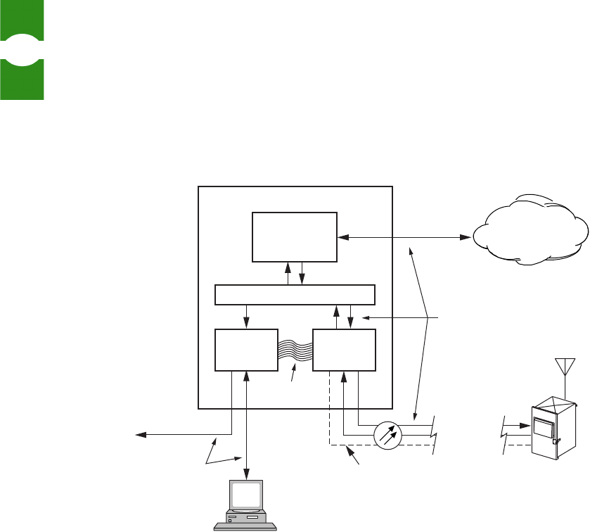
Figure 2 provides a closer look at a working Digivance SDR system. As shown,
the Base Transceiver Station in this system is a BTS application running on the
BTS server. Being software, the BTS application has the advantage that it can be
programmed to process any of a range of Radio Frequency (RF) modulation types.
By comparison, a hardware BTS is restricted to one modulation type.
Figure 2. Closer Look at a Working System
As also shown in Figure 2, the Digivance SDR system involves two ADC cards in
the BTS server: the Host PCIx Card and the Host Network Card. The Host PCIx
Card is the “host unit” referred to on EMS screens. It communicates with the BTS
application over the PCIx bus and, over the fiber interface, with the ADC remote
unit. The Host Network Card is a communication card allowing access to the Host
PCIx Card from the BTS server. The EMS computer plugs into the Host Network
Card DB9 service port. The Host Network Card also provides one input and one
output RJ-45 connector for connecting to other SDR host units in a Control Area
Network (CAN). Up to 24 host units can be networked in this way into one EMS
system. (In an EMS system consisting of a single, collocated host/remote pair, the
Host Network Card can be eliminated by plugging the EMS computer into the
DB9 service port on the remote unit.)
REMOTE
UNIT
BTS SERVER
BSC
NETWORK
HOST
NETWORK
CARD
HOST
PCIx
CARD
PCIx BUS
BASE STATION
APPLICATION
(SDR)
A-bis
INTERFACE
DB-9
UP TO 8
LOGICAL RF
CHANNELS
DIVERSITY
FIBER
(OPTIONAL)
CAN
POWER
EMS
UP TO 24
OTHER HOST
NETWORK
CARDS
19442-A
DIGITALLY
ENCODED
RF SIGNALS
STATUS
ALARMS
USER
REQUESTS
MANAGEMENT
DATA
Introduction to EMS Data Flow
Element Management System (EMS) 4.0 User Manual
5
1.2 Data Flow
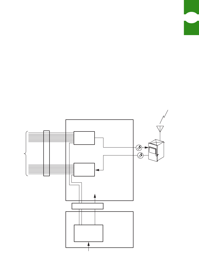
Data flow between a host unit and remote unit consists of at least one forward path
and one reverse path. In diversity systems, there is a secondary reverse path, also.
Figure 3 shows the data flow. As shown, input to the Host PCIx Card from the
BTS application consists of up to eight “logical RF channels.” On the card these
logical channels are combined into a composite signal to the remote unit. Control
data from the EMS computer is also combined into this signal. In the remote unit,
digital RF data is converted to analog RF signals for the remote unit antenna. Data
flow and operations in the reverse path are essentially the reverse of those in the
forward path.
Figure 3. Data Flow
Logical RF channels are defined by user commands entered in EMS based on type
of signals being received from the BTS application. User commands include RF
modulation type, FCC channel number, and signal gain settings.
19488-A
(8) LOGICAL
CHANNELS
(8) LOGICAL
CHANNELS
COMBINER
SPLITTER
COMPOSITE
SIGNAL
(25 MHz)
CHANNEL
DEFINITION
HOST UNIT
FUNCTIONS
DIGITAL
TO RF
CONVERTER
HOST PCIx CARD
PCIx BUS
SDR
APPLICATION
EMS USER
COMMANDS
CONTROL DATA
HOST
NETWORK
CARD
RF
ANALOG
SIGNAL
Wider View of SDR-Based Network Section 1
Element Management System (EMS) 4.0 User Manual
6
1.3 Wider View of SDR-Based Network
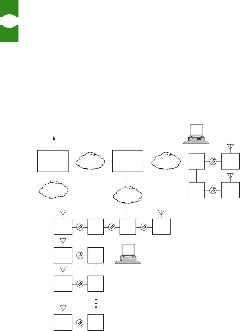
Figure 4 provides a wide view of an SDR base station system. As shown, the BTS
application, running on the BTS server, is controlled over an A-bis interface by a
Base Station Controller (BSC). In an SDR system deployment, the A-bis interface
is over a packet switching network using Voice Over Internet Protocol (VoIP). A
single BSC can control several BTS applications. The BSC, in turn, is controlled
by a Message Switching Center (MSC), using a standard interface called the A-
Interface. The MSC provides connectivity to the external, landline Public
Switching Telephone Network (PSTN). The A-Interface can be carried over a
packet switching network or over traditional T1 lines.
Figure 4. Wide View of an SDR Base Station System
19443-A
LINUX
BTS
LINUX
BTS
REMOTE
UNIT
REMOTE
UNIT
EMS
EMS
LINUX
BTS
REMOTE
UNIT
LINUX
BTS
REMOTE
UNIT
LINUX
BTS
REMOTE
UNIT
LINUX
BTS
REMOTE
UNIT
LINUX
BTS
REMOTE
UNIT
UP TO 24
CAN
VOIP
PACKET
SWITCH
PSTN
PACKET
SWITCH
PACKET
SWITCH
BASE
STATION
CONTROLLER
(BSC)
MESSAGE
SWITCHING
CENTER
(MSC)
MULTIPLE BTSs
(UP TO n DEPENDING
ON BSC CAPACITY)
MULTIPLE
BSCs
(PUBLIC
SWITCHING
TELEPHONE
NETWORK)
T1/E1
Introduction to EMS Common Use Scenarios
Element Management System (EMS) 4.0 User Manual
7
1.4 Common Use Scenarios
This section presents three scenarios in which EMS is used.
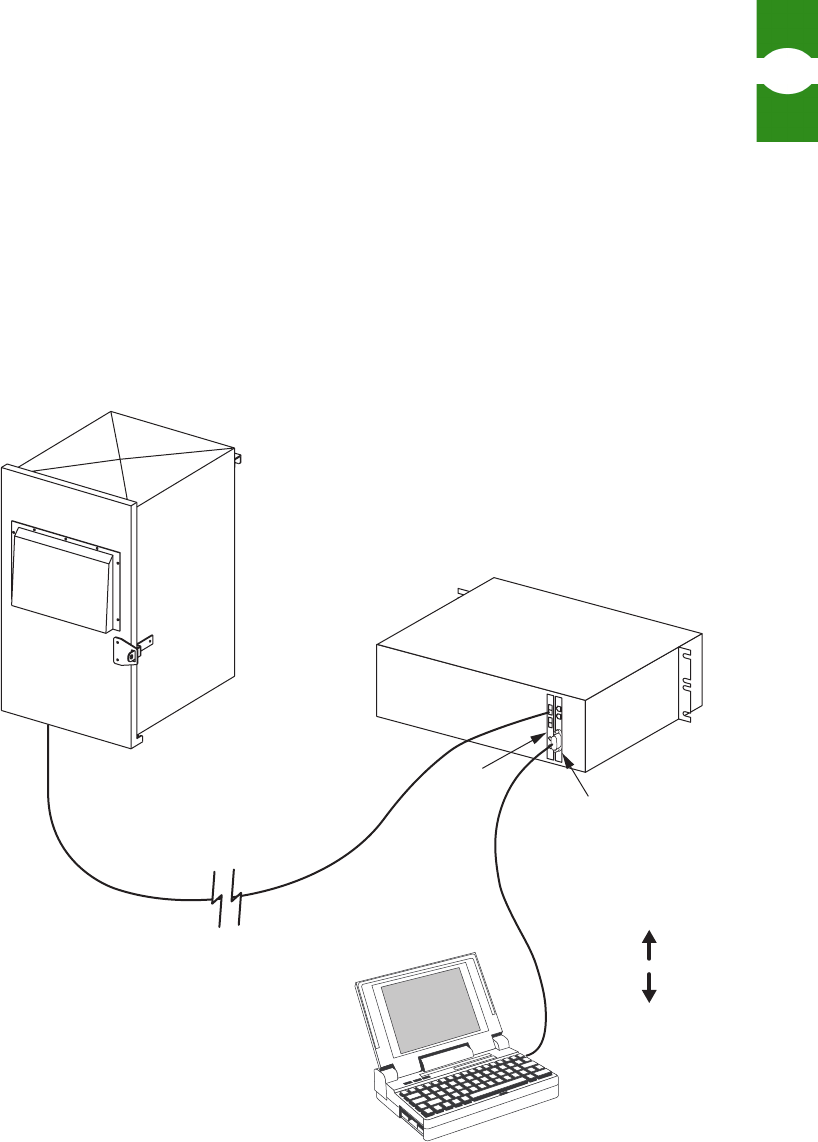
1.4.1 Laptop Use for Installation or Routine Maintenance
In this use scenario, shown in Figure 5, an application engineer or technician
carries EMS to a work site such as a telephone closet or rooftop hut and connects
the EMS computer to a BTS server at that work site. This is done when the units
are installed, using EMS to check and adjust operation as the units are turned up.
RF signal levels can be checked, and attenuation and gain values entered.
Figure 5. Laptop Use Scenario
SETTING
PARAMETERS
SYSTEM
STATUS
17025-A
REMOTE
UNIT
LAPTOP
(LOCAL INTERFACE)
HOST
NETWORK
CARD
PCIx
CARD
LINUX
SERVER
Common Use Scenarios Section 1
Element Management System (EMS) 4.0 User Manual
8
EMS can also be used later to assist in routine maintenance or to respond to
alarms and verify when the situation causing the alarms has been corrected.
1.4.2 Local Office With Multiple Hosts
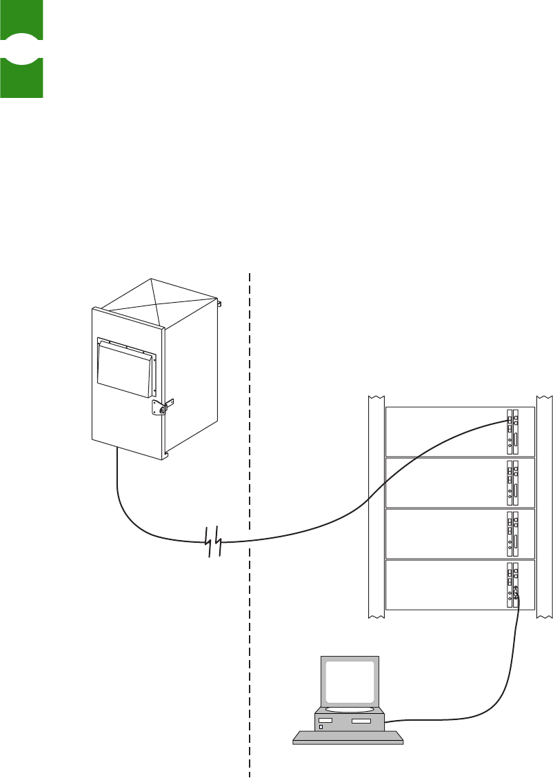
In this use scenario, shown in Figure 6, EMS is permanently installed at a local
office where multiple BTS servers, each equipped with ADC cards, are daisy-
chained in a Controller Area Network (CAN). Each BTS server can house one
host-remote pair. EMS provides monitoring of network performance and quick
identification alarm conditions anywhere in the network.
Figure 6. Local Office Scenario
REMOTE
UNIT
EMS
19445-A
LINUX SERVERS
Introduction to EMS Common Use Scenarios
Element Management System (EMS) 4.0 User Manual
9
1.4.3 SNMP Manager and Proxy Agents
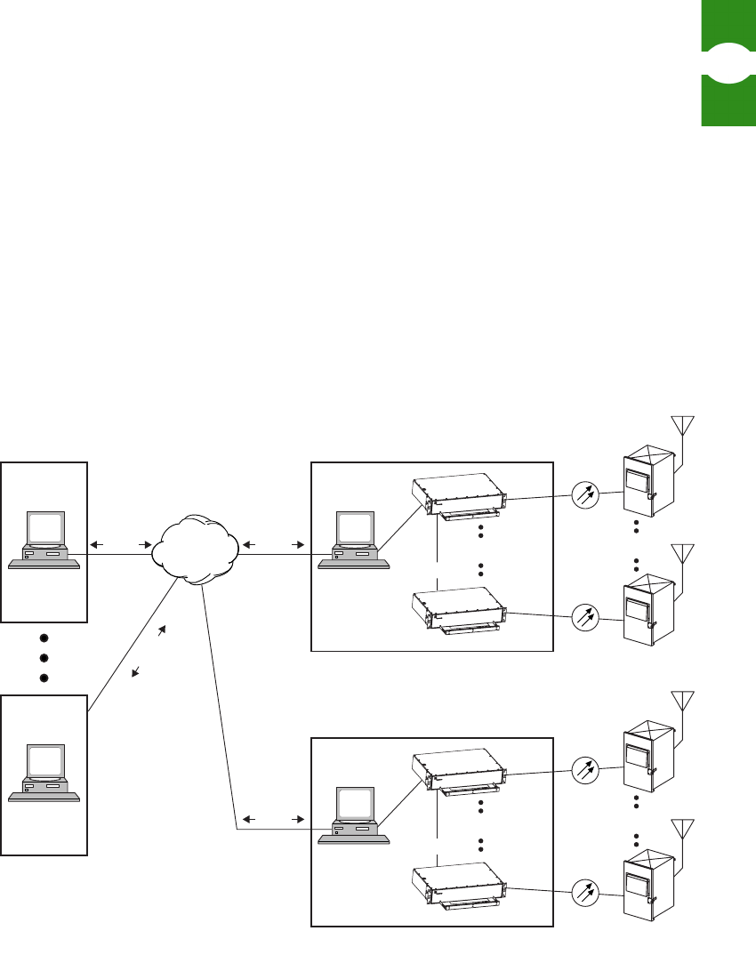
In this use scenario, shown in Figure 7, an analyst with SNMP manager software
and internet access, manages one or more EMS systems with SNMP proxy agent
software and internet access. Using the SNMP manager, the analyst can request
and receive individual parameter values such as voltage readouts. The analyst can
also set certain parameters values such as operating mode to remotely configure
host/remote pairs. The interface also provides automatic reporting of alarms.
SNMP (Simple Network Management Protocol) is a common standard for inter-
network management of online devices using internet protocol (TCP/IP or UDP/
IP). SNMP manager and proxy agent software are available from ADC. The ADC
manager software is called “StarGazer.”
Figure 7. EMS SNMP Application
BTS
SERVER
BTS
SERVER
REMOTE
UNIT
19447-A
INTERNET
PROTOCOL
NETWORK
OPERATIONS
CENTER
SNMP
V1, V2C
SNMP MGR
MIB
BUILDING 1
EMS
SNMP AGENT
MIB
EMS
SNMP AGENT
MIB
NETWORK
OPERATIONS
CENTER
SNMP MGR
MIB
ETHERNET
TCP/IP
UDP/IP
SNMP
V1, V2C
ETHERNET
TCP/IP
UDP/IP
REMOTE
UNIT
UP TO 24 UP TO 24
BTS
SERVER
BTS
SERVER
REMOTE
UNIT
BUILDING n
REMOTE
UNIT
UP TO 24 UP TO 24
CAN
CAN
PDUs
PDUsPDUs
PDUs