ADC Telecommunications DSR0805A Digivance WBDR Base Station User Manual EMSUser
ADC Telecommunications Inc Digivance WBDR Base Station EMSUser
Contents
wbdr part 7
Screen-Based Reference EMS Pull-Down Menus
Element Management System (EMS) 4.0 User Manual
59
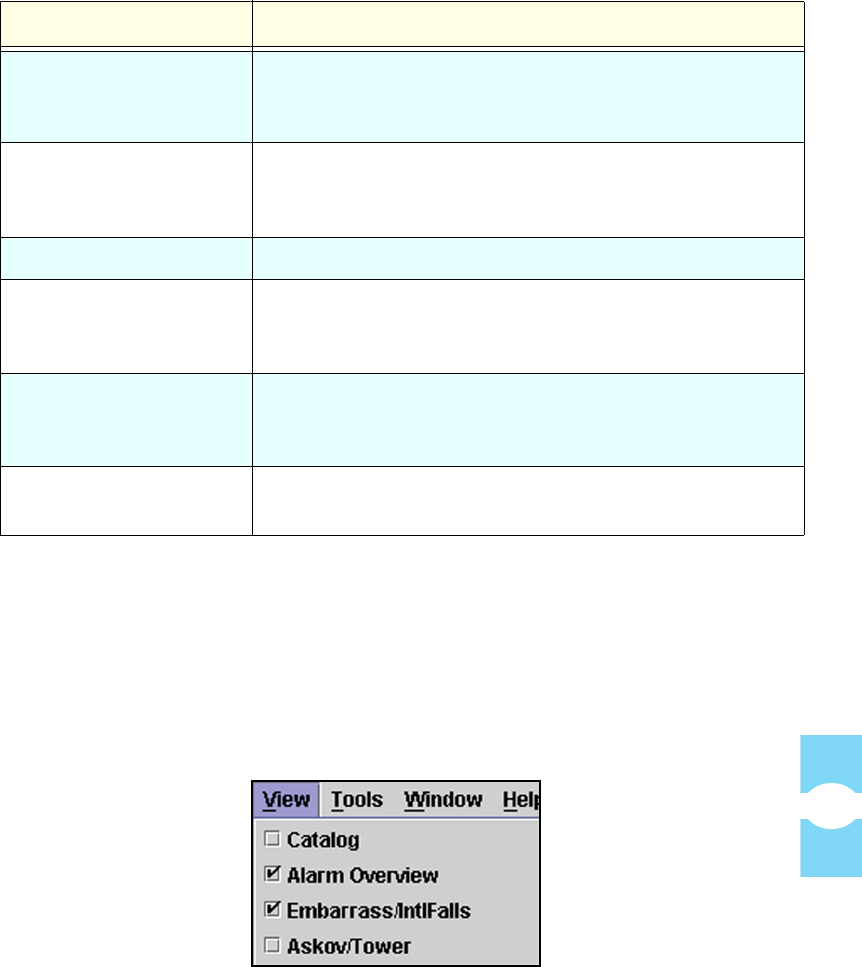
4.1.3 View Menu
The View menu, shown in Figure 50, contains two items that are always present,
Catalog and Alarm Overview.
In addition, as shown, this menu contains one item for each host/remote pair
currently known to EMS.
Figure 50. View Menu Example
Log File Name Path name of directory (folder) where EMS log file is stored
(see next item). To change, click on the field and browse to
select a file or key in a path name in the dialog window.
Days to save before
trimming
Number of days an entry remains in the log file before being
automatically deleted by the system. To change the setting,
key in a number (1-60).
Modem Initialization This field is not currently used.
EMS Link Timeout
(minutes)
Number of minutes EMS spends looking for a network
element before recording an EMS Link Status alarm.
Select using pull-down menu.
Cataloging Time Number of seconds EMS spends looking for host/remote
pairs on startup and on ToolsÞRefresh Catalog requests.
Select using pull-down menu.
Demo Mode No = Demo Mode off. Yes = Demo Mode on. Do not use
demo mode when real network elements are connected!
Table 4: View Menu Items (Continued)
MENU ITEM DESCRIPTION

EMS Pull-Down Menus Section 7
Element Management System (EMS) 4.0 User Manual
60
The View menu is built at start up and rebuilt whenever calaloging is requested by
a user selection of ToolsÞRefresh Catalog. Table 5 describes the selections
available on the View menu.
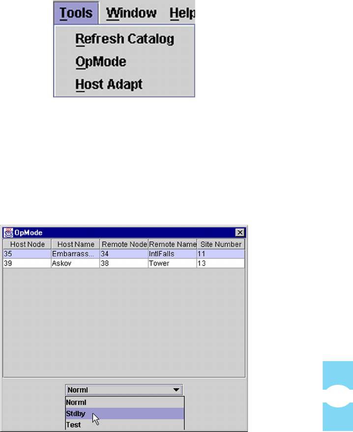
4.1.4 Tools Menu
The Tool s menu, shown in Figure 51, has three items, Refresh Catalog,
Opmode, and Host Adapt.
Table 5: View Menu Items
MENU ITEM DESCRIPTION
Catalog This item is always present. Selecting it causes EMS to look
for and identify all network elements connected and known.
Selecting this item also causes the View menu to be rebuilt.
For Catalog display, see Topic 4.2 on page 65.
Alarm Overview This item is always present. Selecting this item displays an
alarm summary with a an alarm status indicator for each
known network element and an alarm history indicator for
each alarm that has not been acknowledged. The Alarm
Overview is described in Topic 4.3 on page 66.
NotNamed/NotNamed This item is only present if a host/remote pair seen by EMS
have not yet been given site names. You should assign site
names as described in Topic 3.4 on page 31.
<SiteName/SiteName> (“Askov/Tower,” for example) displays the selected host/
remote pair alarm windows. From the alarm windows you
can select from the listed information tabs including:
• For the Host Unit: Alarms, RF, Host, DC
Pwr, Ext Alm, Prg Load, and Config (see
Topic 4.4, Host Displays, on page 69).
• For the Remote Unit: Alarms, RF, STM,
DC Pwr, Ext Alm, Prg Load, and Config
(see Topic 4.5, Remote Displays, on page
80).
Screen-Based Reference EMS Pull-Down Menus
Element Management System (EMS) 4.0 User Manual
61
Figure 51. Tools Menu
Selecting Refresh Catalog causes EMS to look again for host/remote pairs. EMS
then rebuilds the list of host/remote pairs in the View menu, providing a way to
get to the detail information for those pairs, as described in the previous
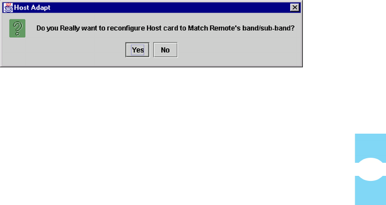
topic.Selecting Opmode displays a window that can be used to select an operating
mode for a host unit or remote unit. Figure 52 shows the Opmode window with
the pull-down menu used to select operating mode.
Figure 52. Opmode Window
To set operating mode for a host/remote pair
1. From the Tools menu, select Opmode to display a table of all currently
known host/remote pairs.

EMS Pull-Down Menus Section 7
Element Management System (EMS) 4.0 User Manual
62
2. Click on the table row for the host/remote pair of interest.
3. For a description of the modes, refer to Table 6.
CAUTION! Care is needed to prevent damage to the system in Test Mode. Test
Mode causes the system to ignore alarms that would otherwise prevent RF sig-
nals from being transported.
4. Select an operating mode using the pull-down menu after first checking the
CAUTION statement above.
To stop an operating mode for a host/remote pair
Stop an operating mode by selecting another mode. (In the end, select Norml
mode to return the host/remote pair to normal operation.)
Table 6: Host Operating Modes
MODE DESCRIPTION
PrgLd
FPGALd
These modes happens automatically when a control program or FPGA is
being downloaded to a network element as described in Topic 3.14 on
page 50.
Norml This is the normal operating mode. In this mode RF signals can be
transported normally.
Stdby This mode can be started by selected Stdby from the pull-down menu. In
Standby mode, the host unit stops transporting RF signals and tries to
conserve power.
Stdby mode can be exited by selecting Norml or Test.
Test This mode can be started by selecting Test from the pull-down menu. In
Test mode, the host/remote pair keeps transporting RF signals even if an
alarm exists that would otherwise stop signal transport. This mode is used
during installation to turn up a host unit or remote unit and start it
transporting RF signals. Alarms would otherwise prevent RF signals from
being transported.
Test mode can be exited by selecting Norml or Stdby.
CAUTION! Care is needed to prevent damage to the system in Test
Mode!
Screen-Based Reference EMS Pull-Down Menus
Element Management System (EMS) 4.0 User Manual
63
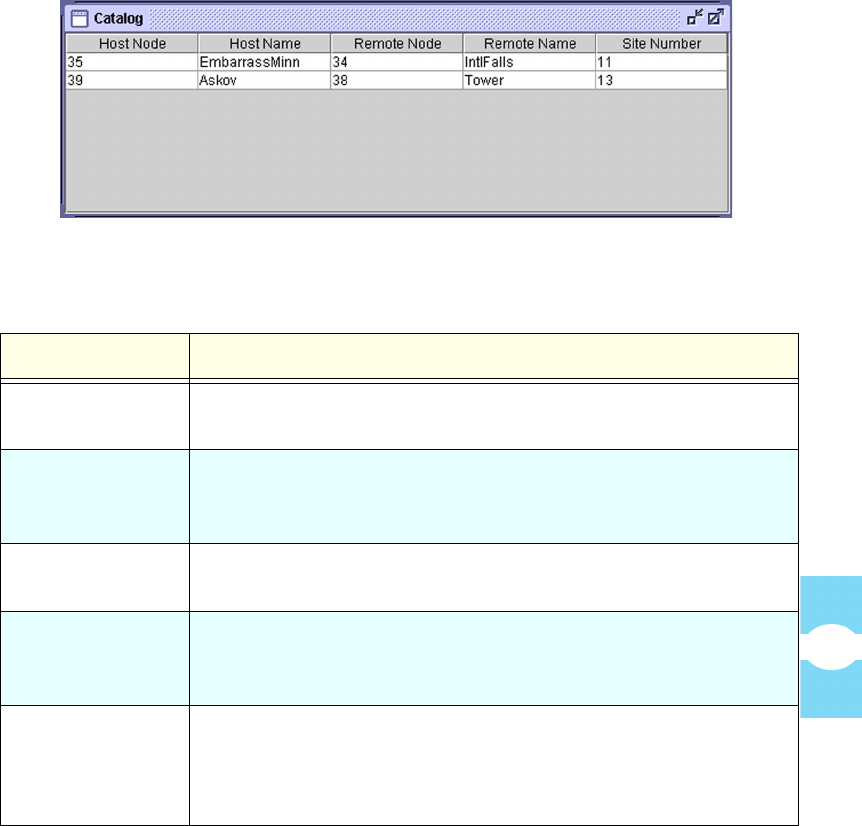
Selecting Host Adapt activates a function that can be used to match the host unit
band and sub-band with the remote unit.
To set the Host Unit Band and Sub-Band to match the Remote Unit
1. From the Tools menu, select Host Adapt.
2. In response to the warning dialog shown in Figure 53, click on Yes. For nor-
mal operation, the host unit and remote unit must be set to the same band and
sub-band.
NOTE: The only practically possible reason you would ever have to answer No to
this dialog is if a new remote unit being installed for an existing system was spec-
ified incorrectly and thus does not match the existing system band and sub-band.
In such a case, as soon as you hook up the remote unit, you will get a Hardware
Mismatch error (see Table 10: Host Major Alarms When Faulted on page 69).
Forcing the host unit to adapt to the wrong band and sub-band in this situation
would result in loss of some existing values for logical channels such as FCC
channel numbers and gain settings.
Figure 53. Host Adapt Warning
4.1.5 Window Menu
The Window menu, at any moment in time, contains an item for each EMS
window currently open, either in displayed or minimized form. Clicking on an
item causes the corresponding window to come to the foreground (with respect to
other displayed windows).
The Window menu always contain two items, NOC-NEM Terminal and Alarm
Overview because these windows are always open. Figure 54 shows an example
of a Window menu containing an additional item for a host/remote pair. Table 7
describes the menu items.

EMS Pull-Down Menus Section 7
Element Management System (EMS) 4.0 User Manual
64
Figure 54. Window Menu Example
4.1.6 Help Menu
Table 8 describes the selections available on the Help menu.
Table 7: Window Menu
MENU ITEM DESCRIPTION
NOC-NEM Terminal This item is always present. Selecting this item brings
the NOC-NEM Terminal window to the foreground of
the current display. This window can be used to view
user-entered commands, system responses, and
automatic status messages and for all host/remote pairs
currently accessible through the Maintenance Interface.
For a description of NOC-NEM commands and
messages, see Section 5 on page 93.
Alarm Overview This item is always present. Selecting this item brings
the AlarmOverview window to the foreground of the
current display. For a description, see Topic Topic 4.3,
Alarm Overview, on page 66.
<SiteName/SiteName> This item will be present for a particular host/remote
pair if a window is currently open showing the alarm
detail for that pair. Selecting the item brings the detail
window to the foreground.
Table 8: Help Menu Items
MENU ITEM DESCRIPTION
Help This item has no function.
About EMS Selecting this item displays a window identifying the EMS
version being used.
Screen-Based Reference Catalog
Element Management System (EMS) 4.0 User Manual
65
4.2 Catalog
The Catalog window, displayed by selecting ViewÞCatalog, displays a table of
all network elements currently known to EMS. Figure 55 shows an example. The
table contains one row for each host/remote pair. For a description of the fields,
refer to Table 9, below.
Figure 55. Catalog Example
Table 9: Catalog Fields
FIELD DESCRIPTION
Host Node Numeric identifier for a particular host unit. This number is
assigned by the system.
Host Name User-assigned name for the host unit. Equivalent to the “site
name.” Can be entered or changed using the Config tab in the Host
display (see Topic 4.4.6 on page 78).
Remote Node Numeric identifier for a particular remote unit. This number is
assigned by the system based on the host node value.
Remote Name User-assigned name for the remote unit. Can be entered or
changed using the Config tab in the remote display (see Topic
4.5.7 on page 90).
Site Number User-assigned number for the host/remote pair. When a new site
number is entered, EMS changes the host node and remote node
values. (A ToolsÞRefresh Catalog is required for these new
values to be correctly displayed.)
Alarm Overview Section 7
Element Management System (EMS) 4.0 User Manual
66
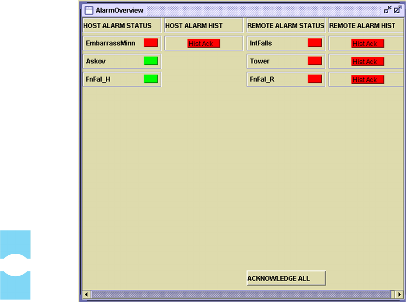
4.3 Alarm Overview
The Alarm Overview window, displayed by selecting ViewÞAlarm Overview,
provides a visual alarm summary for all network elements currently known to
EMS. Figure 56 shows an example.
As shown, the display divides into two side-by-side sections, with host units in the
left section and remote units in the right section. Each side-by-side pair of units is
one operational host/remote pair. If EMS finds any unit without a pair, just the
found unit is shown; the other half of the row is blank.
Figure 56. Alarm Overview Example
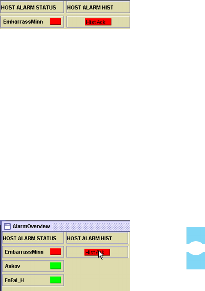
For each network element, there are two indicators, shown in Figure 57:
Screen-Based Reference Alarm Overview
Element Management System (EMS) 4.0 User Manual
67
Figure 57. Alarm Overview Indicators
•(HOST or REMOTE) ALARM STATUS Indicator—Always
displays. Indicates whether an alarm exists for the identified unit:
•Red = one or more major alarms exist. A major alarm places the
identified unit in standby operating mode (stopping RF functions).
•Ye l lo w = one or more minor alarms exist at the network element. A minor
alarm allows the unit to continue functioning in normal mode.
•Green = no alarms exist at the network element.
An alarm status indicator in an alarm state (red or yellow) can only be
returned to normal (green) by correcting the associated problem in the host or
remote unit.
•(HOST or REMOTE) ALARM HIST Indicator—Individually
labeled “Hist Ack,” displays for a unit when an alarm is reported for
that unit. It remains displayed until the alarm is acknowledged within
this same window.
An individual alarm is acknowledged by clicking on the HIST ACK indicator (as
shown in Figure 58) then clicking on the OK button in the Alarm History Info
dialog (shown in Figure 59).
Figure 58. Clicking on the Alarm History Indicator
Alarm Overview Section 7
Element Management System (EMS) 4.0 User Manual
68
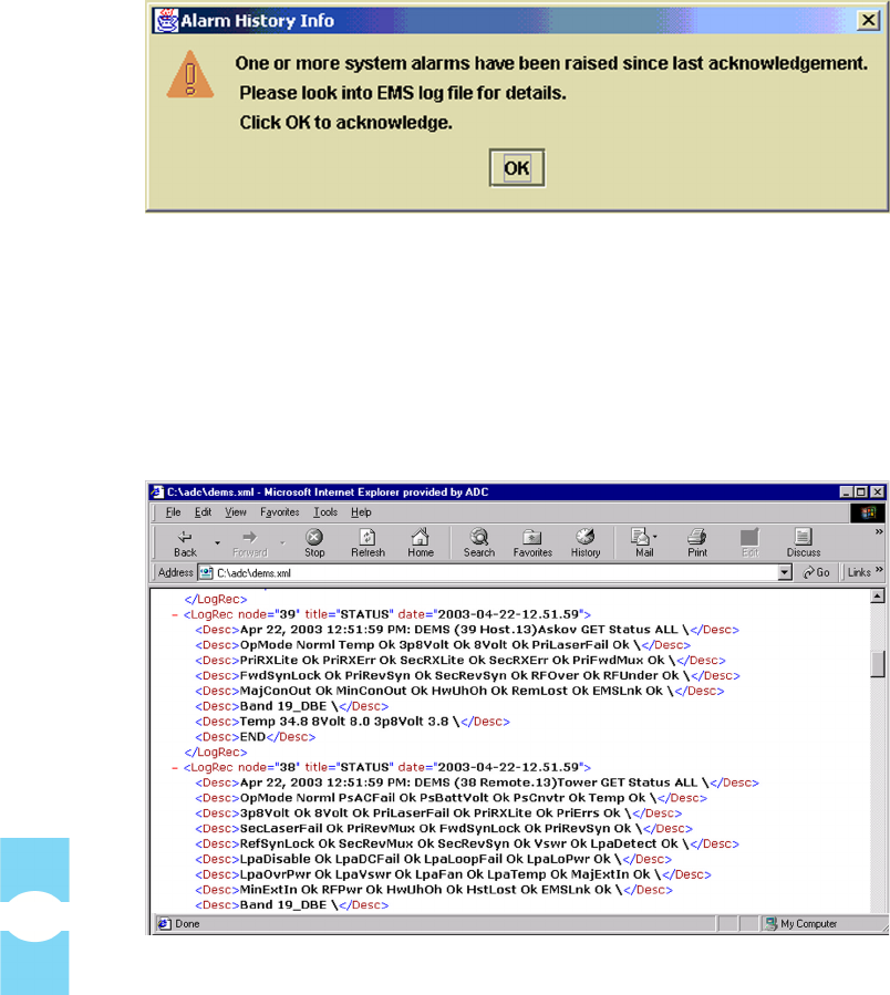
Figure 59. Alarm History Info Dialog
After this is done, the indicator disappears from the display. As advised in the info
window, however, whenever acknowledging an alarm, you should also check the
EMS log file for details on how the alarm was reported. Figure 60 shows a log file
display in the internet browser. For instructions on using the browser to view the
log file, see Topic 3.15 on page 53.
Figure 60. Viewing Alarm Details in EMS Log File
For more information on specific alarms, refer to Topic Topic 4.4.1, Host Alarms
Window, on page 69 for host alarm information or to Topic Topic 4.5.1, Remote
Alarms Window, on page 80 for remote alarm information.
Screen-Based Reference Host Displays
Element Management System (EMS) 4.0 User Manual
69
4.4 Host Displays
The EMS “host displays” include seven windows with information available for
any operational host connected to the EMS/Host/Remote Comm port. The “host
unit” in a Digivance SDR system is the Host PCIx Card in the BTS server.
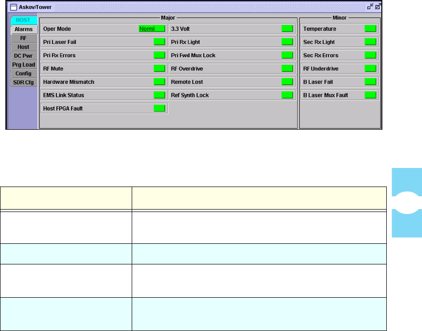
4.4.1 Host Alarms Window
The host Alarms window, shown in Figure 61, contains alarm indicators returned
from the host unit. In general, GREEN indicates okay, RED indicates that a major
alarm exists, and YELLOW indicates that a minor alarm exists. A major alarm
causes RF functions to be halted; a minor alarm allows RF functions to proceed as
normal. The indicators are refreshed about every three seconds. Table 10 lists the
indicators and describes each one. For a more thorough description, refer to the
user manual for the host unit.
Figure 61. Host Alarms Window
Table 10: Host Major Alarms When Faulted
ALARM INDICATOR DESCRIPTION WHEN FAULTED
Oper Mode The operating mode is not “Norml.” For a description of
other modes, see Topic 4.1.4, Tools Menu, on page 60.
3.3 Volt The 3.3 Volt onboard supply is too low.
Pri Laser Fail The forward path primary fiber laser is not sending light
(no light from host unit to remote unit).
Pri Rx Light No light is being received from the primary fiber (no
light from remote unit to host unit).

Host Displays Section 7
Element Management System (EMS) 4.0 User Manual
70
Pri Rx Errors Multiple errors are occurring on primary fiber. Error rate
has exceeded 10–6 (one bit error per million bits).
Pri Fwd Mux Lock The forward path primary fiber phase-locked-loop is out
of lock.
RF Overdrive The forward path RF signal level is too high.
Hardware Mismatch Host unit and remote unit are on different bands.
Remote Lost Host cannot communicate with remote unit.
EMS Link Status EMS has not heard from host unit for the number of
minutes currently specified by the EMS Link Timeout
parameter (see Topic Topic 3.6, Setting EMS Link
Timeout, Cataloging Time, Demo Mode, on page 34).
Ref Synth Lock The reference synthesizer is out of lock.
Host FPGA Fault Fault was reported in FPGA chip on Host PCIx Card.
Table 11: Host Minor Alarms When Faulted
ALARM NAME DESCRIPTION
Temperature The host unit temperature is too hot. The temperature is
sensed to be greater than 70º Celsius (158º Fahrenheit).
Likely cause is a fan failure.
Sec Rx Light No light is being received from the secondary fiber (no
light from host unit to remote unit).
Sec Rx Errors Multiple errors are occurring on the secondary fiber.
Error rate has exceeded 10–6 (one bit error per million
bits).
Sec Rev Synth Lock The secondary reverse path synthesizer is out of lock.
RF Underdrive The forward path RF signal level is too low.
B Laser Fail Not used. Always green.
B Laser Mux Fault The secondary fiber phase-locked-loop is out of lock.
Table 10: Host Major Alarms When Faulted (Continued)
ALARM INDICATOR DESCRIPTION WHEN FAULTED