ADC Telecommunications DSR0805A Digivance WBDR Base Station User Manual EMSUser
ADC Telecommunications Inc Digivance WBDR Base Station EMSUser
Contents
wbdr part 2
Overview of User Interfaces Section 1
Element Management System (EMS) 4.0 User Manual
10
1.5 Overview of User Interfaces
EMS provides two user interfaces:
• A windows-based graphical user interface, called the “Maintenance
Interface,” which is intended for use in most situations; and
• A character interface, called the NOC-NEM interface, which can be
accessed remotely using a terminal or a computer with a terminal
emulator program.
NOTE: For convenience, the character interface is also available within the Main-
tenance Interface using a user-selectable character window.
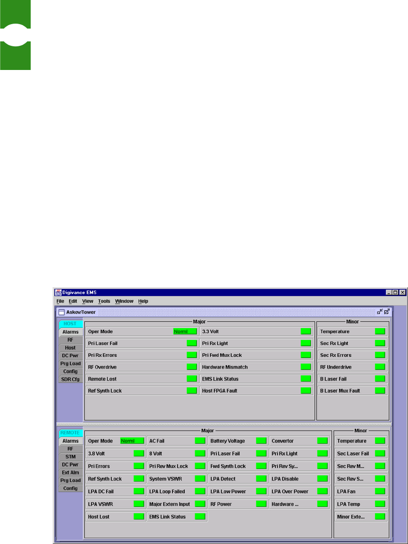
1.5.1 Maintenance Interface
The Maintenance Interface is a graphical user interface (GUI) with a menu toolbar
and “dashboard” displays containing indicators. Figure 8 shows an example, a
display with alarm details for a host/remote pair connected to EMS.
Figure 8. Maintenance Interface Example
Introduction to EMS Overview of User Interfaces
Element Management System (EMS) 4.0 User Manual
11
The dashboard displays, refreshed about once every three seconds, allow you to
quickly assess the status of host/remote pairs by checking the indicator colors. The
color green indicates “okay.” Red and yellow, respectively, indicate major and
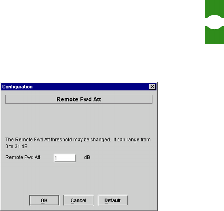
minor alarms. The Maintenance Interface also has dialogs used to set values such
as remote forward attenuation as shown in Figure 9.
Figure 9. Dialog Example
1.5.2 NOC-NEM Interface
The NOC-NEM interface is a “character interface” that can be accessed using a
direct data link connection between a terminal, or a computer with a terminal
emulator program, and a remote computer on which EMS is running. The NOC-
NEM interface is also available as a window within the Maintenance Interface, in
which case it provides a character, command line interface for the same host/
remote pairs as are being reported in the graphical displays.
When used side by side with EMS graphical displays, the NOC-NEM interface
augments system function through such features as automatic status updates,
immediate alarm notification, easy retrieval of alarm and status history stored in
the EMS log file, and ability to send ALL commands affecting multiple network
elements at the same time.
Overview of User Interfaces Section 1
Element Management System (EMS) 4.0 User Manual
12
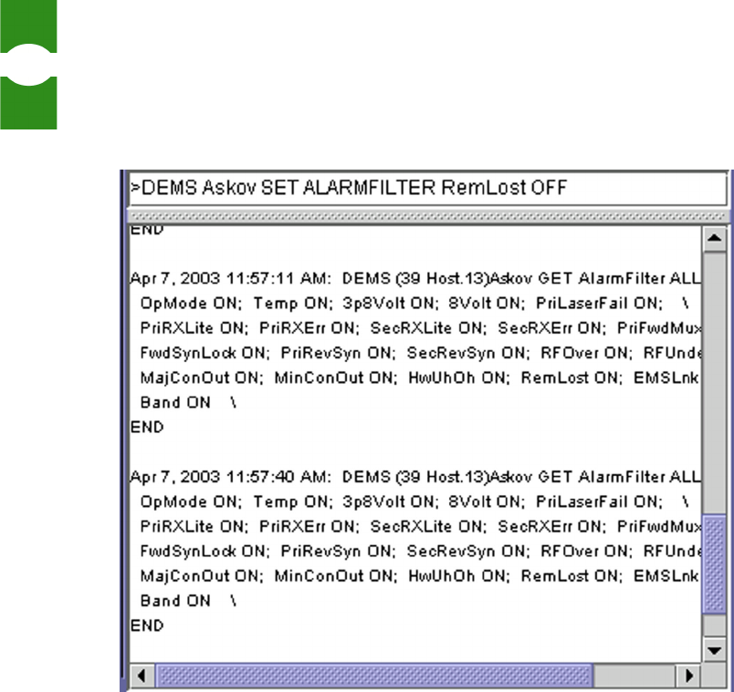
Figure 10 shows an example of a NOC-NEM interface display. Appearance will
vary depending on the terminal or terminal emulator program being used.
Figure 10. NOC-NEM Interface Example
Using NOC-NEM, you can perform most of the tasks done using the Maintenance
Interface. Below is an example of a command and response message.
Apr 7, 2003 12:17:21 PM: DEMS (39 Host.13)Askov GET Alarm
3p8Volt \
3p8Volt Ok \
END

Introduction to EMS Overview of EMS Tasks
Element Management System (EMS) 4.0 User Manual
13
1.6 Overview of EMS Tasks
Table 1 summarizes the tasks done using EMS.
Table 1: Summary of EMS Tasks
TASK DESCRIPTION
Determine which network
elements are currently con-
nected
You can do this inside the Maintenance Interface by
using a menu item to refresh the “catalog” of host/
remote pairs. If using the NOC-NEM interface, you can
enter a command to do this.
Enter site name and site
number
When turning up a host/remote pair and “introducing”
the units to EMS, you can give them a site name and
(host only) site number. If using the NOC-NEM inter-
face, you can enter a command to do this.
Check for alarms You can check an alarm overview window to determine
if any network element has an alarm. If so, you can
view an alarm detail window to check individual alarm
indicators in the alarmed network element. Any new
alarm also causes the NOC–NEM window, if open, to
scroll down with new text as the alarm is reported.
Acknowledge alarms Using the alarm overview window, you can also deter-
mine which alarms, if any, remain to be investigated.
Every alarm, when it first occurs, is flagged with an
alarm history indicator (red or yellow). The indicator
remains in the window until someone clicks on it to
acknowledge that the alarm has been noticed.
Determine current status You can check the current status of any network ele-
ment using seven function-related windows (for exam-
ple, there are separate windows for optics functions and
DC power). In addition, the NOC–NEM window dis-
plays periodic messages summarizing the current status
of all connected pairs.
Obtain status history and
alarm history text
Using the NOC–NEM window, you can retrieve status
and alarm messages written to the EMS log file. You
can also scroll back in the NOC-NEM window to see
which events preceded an error condition.

Use of Ports Section 1
Element Management System (EMS) 4.0 User Manual
14
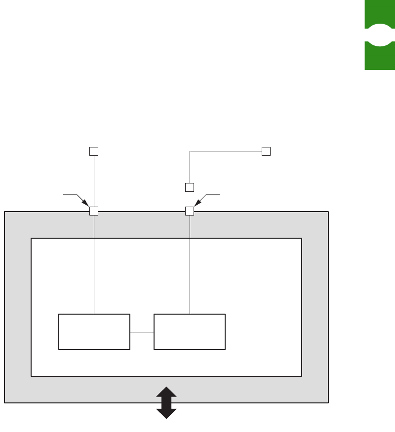
1.7 Use of Ports
EMS uses a DB-9 port with an RS-232 DCE interface, identified in the software
as the “EMS/Host/Remote Comm Port,” to communicate with LRCS network
elements. This port is used by the Maintenance Interface. It also provides the
information available in the NOC-NEM window within the Maintenance
Interface. A second serial port, identified in the software as the “NOC Comm
Port,” can optionally be used to provide NOC-NEM access to a remote terminal or
to a remote computer running a terminal emulator program. Figure 11 provides a
schematic of the ports from the perspective of the EMS software.
Physically the ports have the following requirements:
•EMS/Host/Remote Comm Port—This port connects to the PC-
compatible receptor on one end of the straight-through RS-232 cable
provided with the Digivance system. The DB-9 plug on the other end
of the cable, in a working system, connects to a DB-9 receptor either
on a Host Network Card (in a BTS server) or on an ADC remote unit.
When connected directly to a remote unit, the EMS system is used for
a single, collocated host/remote pair.
Define RF logical channels For each logical RF channel, you can select modulation
type and FCC channel number.
Check RF signal levels You can check signal levels of RF forward and reverse
path signals as measured on the PCIx card. Alarm indi-
cators provide details on any states preventing normal
signal transport.
Enter RF signal gain and for-
ward path attenuation
You can enter signal gain settings for RF forward path,
reverse path, and diversity path (if present) for any log-
ical RF channel. You can adjust forward path attenua-
tion affecting the strength of the RF analog signal
transmitted from the remote unit antenna.
Download controller and
FPGA files
Using the Prg Load window, you can download pro-
gram files to the host unit or remote unit. For each unit,
these files include a control program and a Field Pro-
grammable Gate Array (FPGA).
Table 1: Summary of EMS Tasks (Continued)
TASK DESCRIPTION
Introduction to EMS Use of Ports
Element Management System (EMS) 4.0 User Manual
15
•NOC Comm Port—This port may be used to connect to a direct data
link with the remote terminal or terminal emulator computer. Cables
and equipment, not provided, must support the RS-232 ASCII data
flow between the EMS computer and the remote terminal or terminal
emulator computer.
Figure 11. EMS Ports
19454-A
NOC-NEM
INTERFACE
MAINTENANCE
INTERFACE
EMS/HOST/REMOTE
COMMUNICATION
PORT
NOC
COMMUNICATION
PORT
RS-232
RS-232
ASCU
DB-9
DB-9
SERVICE INTERFACE CONNECTION
REMOTE TERMINAL
OR TERMINAL EMULATOR
CUSTOMER
PROVIDED
COMPUTER
DIGIVANCE ELEMENT
MANAGEMENT SYSTEM
USER

Use of Ports Section 1
Element Management System (EMS) 4.0 User Manual
16

2 I
2 I2 I
2 IN
NN
NS
SS
ST
TT
TA
AA
AL
LL
LL
LL
LA
AA
AT
TT
TI
II
IO
OO
ON
NN
N
A
AA
AN
NN
ND
DD
D S
S S
SY
YY
YS
SS
ST
TT
TE
EE
EM
MM
M
C
C C
CH
HH
HE
EE
EC
CC
CK
KK
K
Element Management System (EMS) 4.0 User Manual
19
INSTALLATION AND
SYSTEM CHECK
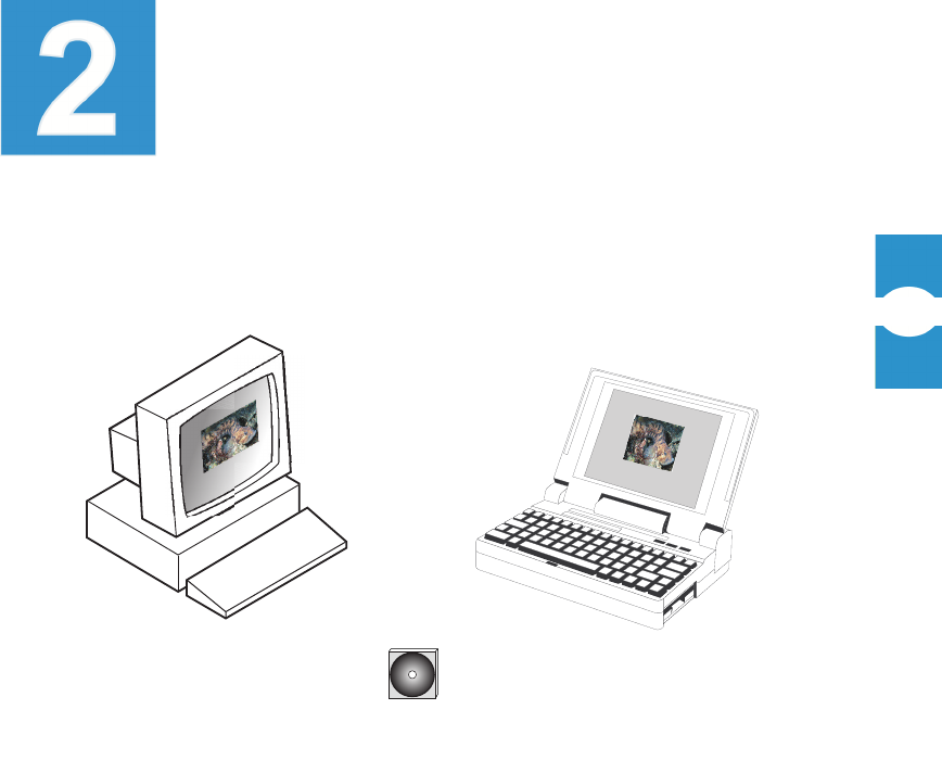
Installation of EMS is an easy task involving downloading and running several
files provided on the installation CD-ROM. You can install EMS on either a PC
or laptop, as shown in Figure 12.
Figure 12. Basic Installation Components
2.1 System Requirements
For EMS to be loaded, the computer must have:
• Pentium® class processor or better
• 256 Meg RAM
• Serial port
• 30 Mb available hard disk space
• CD-ROM drive to install the software
• Windows® operating system (95, 98, NT, or 2000)
CD-ROM WITH EMS
SOFTWARE
OR
PLUS
16803-B

Installation CD Contents Section 2
Element Management System (EMS) 4.0 User Manual
20
2.2 Installation CD Contents
The Element Management System consists of software files supplied on a CD.
These files include:
• The Java™ Runtime Environment from Sun MicroSystems and the
appropriate licensing agreements required for its use.
• The executable files necessary for the Element Management System
software to run on a Windows based personal computer.
The version of the software contained on the CD is listed on the label and can be
verified as the correct version by calling the ADC Technical Assistance Center (1-
800-366-3891 extension 73475, in U.S.A. and Canada; 1-952-917-3475, outside
U.S.A. and Canada).
2.3 Installation Procedure
Installation involves three procedures: installing the Java Runtime System,
installing the EMS software, and completing the installation.
2.3.1 Installing the Java Runtime System
The Java Runtime System contains several files required for the NOC-NEM
interface.
To install the Java Runtime System
1. Exit all Windows programs.
2. Insert the CD-ROM.
3. Select StartÞRun and browse to select the following program:
j2re-1_3_1-win.exe
4. Allow the program to complete running.
This will create several items in the folder, c\Program Files\javasoft.

Installation and System Check Out Installation Procedure
Element Management System (EMS) 4.0 User Manual
21
2.3.2 Installing the EMS Software
The EMS software contains the ADC application files that provide the system
interfaces and functions.
To install the EMS software
Perform the following steps:
1. Copy the following files from the CD-ROM to the folder
c:\My Documents on your computer:
ReadMe_<band>.txt
DEMSINS.exe
where <band> is the bandwidth of the system being installed (800, 1099,
smr, etc.).
2. Use StartÞRun to extract and execute the DEMSINS.exe
program.
This will create several items in the folders c:\ADC\DEMS.
2.3.3 Completing the Installation
This procedure updates some system files on the computer with EMS parameters
and provides an icon on the desktop for use in starting the system.
To complete the installation
Perform the following steps:
1. Restart the computer.
2. Create a shortcut to DEMS.bat located in c:\ADC\DEMS and
drag the shortcut to the desktop.

Installation and System Check Out Connecting to the Host/Remote Pair
Element Management System (EMS) 4.0 User Manual
22
2.4 Connecting to the Host/Remote Pair
The EMS software is now presumed to be correctly installed on the computer, and
can be run alone, but to function as intended it must be connected to one or more
Digivance System host/remote pairs.
For the physical connection between the EMS PC and the host/remote pair, use
the RS-232 serial cable provided with the Digivance hardware.
Connect the cable on the PC to the serial port identified in the software as the
EMS/Host/Remote Comm Port (by default this port is COM1). Connect the other
(DB-9) end of the cable to the SERVICE port on either the host unit or the remote
unit. On both the host unit and the remote unit, the SERVICE port is located on
the front console.
NOTE: When EMS is connected directly to a remote unit, only that remote unit
and the corresponding host unit are visible in EMS. When EMS is connected to a
host unit, however, all LRCS system pairs that are presently on the Controller
Area Network (CAN) bus are visible.
NOTE: For information on how the EMS/Host/Remote Comm port is defined, see
Topic 3.3, Defining EMS Ports, on page 29.
NOTE: Multiple host units can be daisy-chained together in a CAN. For informa-
tion, refer to the user manual for the host unit.
Most of the information contained in the LRCS system can be obtained from
either the host or remote unit ports; however, to update some program files, you
must be connected to the host unit port.

Installation and System Check Out Checking the System
Element Management System (EMS) 4.0 User Manual
23
2.5 Checking the System
After installing the software and (if possible at this time) connecting your
computer to one or more Digivance host/remote pairs, do the following procedure
to check if the system is running correctly
To check the system
1. Doubleclick on the EMS icon.
2. Watch for the EMS banner to come up.
3. Watch for the initial menu bar to come up.
4. Look for the Alarm Summary window which should identify the host/remote
pairs that are currently connected.
5. If the host/remote pairs are not listed, check your port settings and the serial
cable between the EMS computer and the host/remote pair.

Checking the System Section 2
Element Management System (EMS) 4.0 User Manual
24