ADC Telecommunications DSR0805A Digivance WBDR Base Station User Manual EMSUser
ADC Telecommunications Inc Digivance WBDR Base Station EMSUser
Contents
wbdr part 8
Screen-Based Reference Host Displays
Element Management System (EMS) 4.0 User Manual
71
4.4.2 Host RF Window
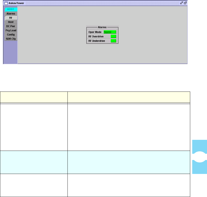
The host RF (Radio Frequency) window, shown in Figure 62, displays two alarm
indicators for the forward path RF composite signal. The window shows operating
mode, also, because a mode other than normal may cause the indicators to report
falsely. Table 12 describes the RF alarms.
Figure 62. Host RF Window
Table 12: Host RF Alarms When Faulted
ALARM NAME DESCRIPTION
Oper Mode The operating mode is not “Norml.” (“StandBy” mode
will cause a green RF Underdrive indicator to falsely
read as red; a red RF Overdrive indicator will falsely
read as green. “Test” mode will have no effect on the
RF indicators. If mode is “PrgLd,” wait for the load to
complete.) For more information on operating mode,
refer to Topic 4.1.4, Tools Menu, on page 60.
RF Overdrive The forward path composite signal level of all channels
from the server is too high. The overdrive threshold is
−3 dBFSrms. See also Oper Mode above.
RF Underdrive The forward path composite signal level of all channels
from the server is too low. The overdrive threshold is
−25 dBFSrms. See also Oper Mode above.
Host Displays Section 7
Element Management System (EMS) 4.0 User Manual
72
4.4.3 Host Window
The Host window identifies the bandwidth that the host is set to and contains two
subsets of alarms, one for the host unit optics functions and one for the host unit
synthesizer functions. The names for these alarms refer in a number of places to
“primary” and “secondary” fibers and “forward” and “reverse” paths. For
clarification (see Figure 63):
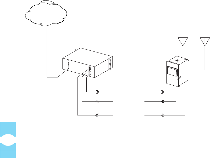
NOTE: The “host unit” in the Digivance SDR system is the Host PCIx Card
within the BTS server shown in Figure 63.
Figure 63. Forward and Reverse Paths
(in Product Model With Secondary Fiber)
• The host unit (Host PCIx Card) will usually have two primary fibers
(connected to host Port 1 and Port 2). These fibers carry the primary
forward path (Port 1) and primary reverse path (Port 2) optical
signals. If Wave Division Multiplexers (WDMs) are used, both
signals may be transported on one fiber between multiplexers on
either end. A free space optics link may also be used.
REMOTE UNIT
19487-A
FORWARD PATH
PRIMARY
REVERSE PATH
FIBER OPTIC
LINK
SECONDARY
REVERSE PATH
(OPTIONAL)
LINUX
SERVER
APIS
BSC
NETWORK
Screen-Based Reference Host Displays
Element Management System (EMS) 4.0 User Manual
73
• Depending on the product model, the host unit (Host PCIx Card) may,
in addition, have a secondary fiber (connected to host Port 3) to
provide a diversity gain option. In this case, the secondary fiber will
carry a secondary reverse path from a secondary antenna.
Synthesizer alarms also refer to the primary forward path, primary reverse path,
and secondary reverse path because the host unit has a separate synthesizer for
each of these paths. The synthesizers are monitored independently; an error
condition in one synthesizer will not affect the others.
Figure 64 shows the Host window. Table 13 describes the optics alarms when
failed. Table 14 describes the synthesizer alarms and band alarm when failed.
Table 16 describes the band indicator.
Figure 64. Host Window
Table 13: Host Optics Alarms When Faulted
ALARM NAME DESCRIPTION
Pri Laser Fail The forward path primary fiber laser is not sending
light (no light from host unit to remote unit).
Pri Rx Light No light is being received from the primary fiber (no
light from remote unit to host unit).
Pri Rx Errors Multiple errors are occurring on primary fiber. Error
rate has exceeded 10–6 (one bit error per million bits).
B Laser Fail Not used. Always green.
Sec Rx Light No light is being received from the secondary fiber.

Host Displays Section 7
Element Management System (EMS) 4.0 User Manual
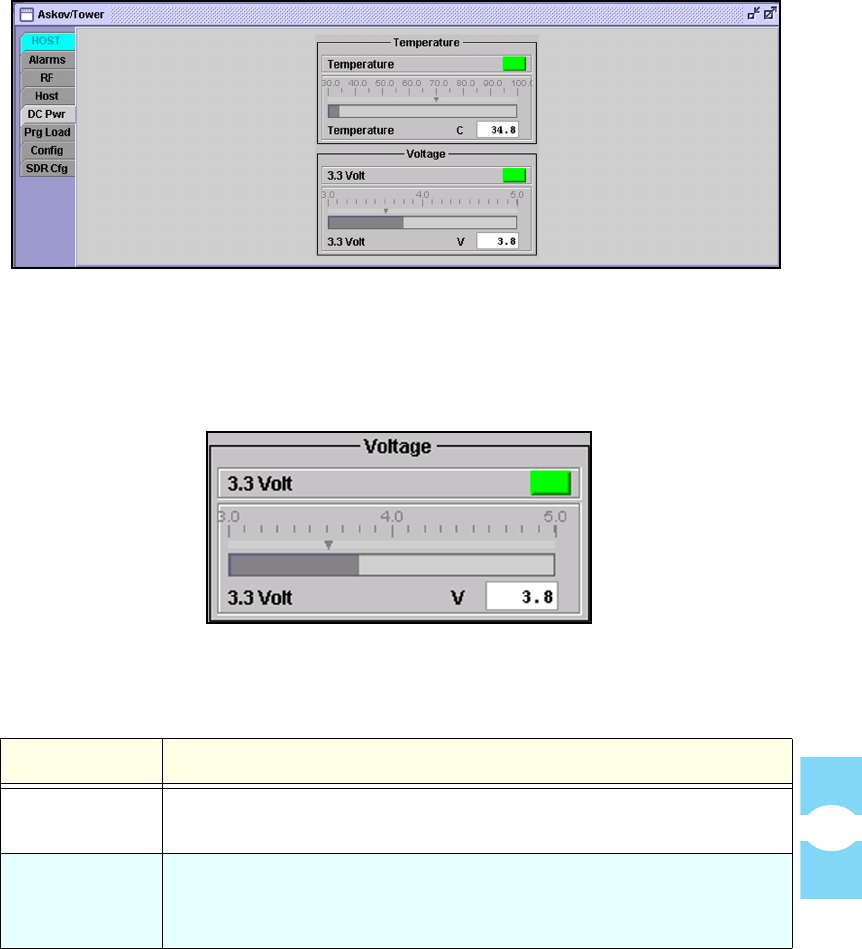
74 4.4.4 Host DC Pwr Window
The host DC PWR (DC Power) window, shown in Figure 65, contains dashboard
displays with readings from the temperature sensor and voltage supply sensors on
the host unit control board. Table 17 describes the dashboard displays.
Sec Rx Errors Multiple errors on secondary fiber. Error rate has
exceeded 10–6 (one bit error per million bits).
Table 14: Host Synthesizer and Band Alarms When Faulted
ALARM NAME DESCRIPTION
Pri Fwd Mux Lock The forward path primary fiber phase-locked-loop is
out of lock.
Ref Synth Lock The reference synthesizer is out of lock.
B Laser Mux Fault The secondary fiber phase-locked-loop is out of lock.
Table 15: FPGA Alarm When Faulted
INDICATOR NAME DESCRIPTION
Host FPGA Fault Fault was reported in FPGA chip on Host PCIx Card.
Table 16: Host Band Indicator
INDICATOR NAME DESCRIPTION
Band Indicates the RF bandwidth and sub-band at which this
unit is running. If the host unit and remote unit are at
different bands, a Hardware Mismatch alarm is
reported (for more information, see Topic 4.4.1, Host
Alarms Window, on page 69).
Table 13: Host Optics Alarms When Faulted (Continued)
ALARM NAME DESCRIPTION
Screen-Based Reference Host Displays
Element Management System (EMS) 4.0 User Manual
75
Figure 65. Host DC Pwr Window
NOTE: For each bar graph in the displays, there is a down-arrow threshold marker
showing the point at which the unit goes into alarm. Figure 66 show an example.
Figure 66. Down-Arrow Threshold Marker (at 3.6 Volt)
Table 17: Host DC Power Display
DISPLAY NAME DESCRIPTION
Temperature Not used. Always green in an SDR application. The Host PCIx Card
has no circuitry for computing and reporting temperature.
Vo l t a g e Shows current readings for the host unit onboard 3.3 Volt supply. A
reading exceeding the threshold indicated by the down arrow triggers
the corresponding alarm.
Host Displays Section 7
Element Management System (EMS) 4.0 User Manual
76
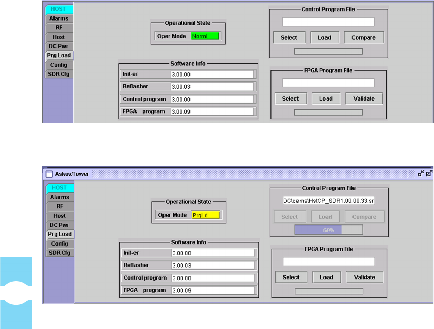
4.4.5 Host Prg Load Window
The host Prg Load (Program Load) window, shown in Figure 67 and Figure 68,
is used to download a program file from the EMS computer to a host unit. The
program file may be a control program or a Field Programmable Program Array
(FPGA).
Table 18 describes the components of the window. For the download procedure,
refer to Topic 3.14 on page 50.
Figure 67. Host Prg Load Window
Figure 68. Program Load in Progress

Screen-Based Reference Host Displays
Element Management System (EMS) 4.0 User Manual
77
Table 18: Host Prg Load Window Components
DISPLAY NAME DESCRIPTION
Operational State
Operating
Mode
This mode is not set here, merely indicated. The host should be in a
Norml mode when starting the download. The mode then changes
automatically to PrgLd or FPGALd.
Control Program File or FPGA Program File
(Unnamed
Field)
<Name><Version>.sr where
<Name> = name of program being downloaded
<Version> = major.minor.rev.build
Select Click on this button to browse for and open the program file.
Load Click on this button to download the selected program file from the
EMS computer to the host unit.
Compare Click on this button to compare the version of the selected program
with the version of the control program already installed on the unit.
Validate Click on this button to determine whether the FPGA on the host is in
a functional state in which an FPGA can be downloaded. For newer
hardware, the FPGA will be reported as “not functional” if the FPGA
software did not successfully download to begin with. If the FPGA is
not functional, the RF system will be in alarm.
NOTE: The response to this button click should be disregarded for
older hardware. The older hardware can be identified by the FPGA
version being “UNKNOWN” (in the FPGA Program field). On this
older hardware, the FPGA is not downloadable.
Software Info
Init-er Host Initialization Program version
Reflasher Host Reprogram Program version
Control
program
Host Control Program version (<Band> = bandwidth)
FPGA program Field Programmable Gate Array version. If unit is older type with
non-replaceable array, this field will say “UNKNOWN.”
Host Displays Section 7
Element Management System (EMS) 4.0 User Manual
78
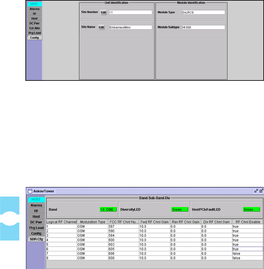
4.4.6 Host Config Window
The host Config (Configuration) window, shown in Figure 69, shows the site
number and site name of the host unit currently selected for view.
Figure 69. Host Config Window
Clicking on the Edit button for Site Number or Site Name causes a dialog
window to be displayed. The dialog window can be used to enter or edit a site
number or site name. For instructions, refer to Topic 3.7 on page 36.
4.4.7 Host SDR Cfg Window
The host SDR Cfg window, shown in Figure 70, is used to configure the
software-defined radio channels within the Host Unit. Table 19 and Table 20
describe the window fields.
Figure 70. Host SDR Config Window

Screen-Based Reference Host Displays
Element Management System (EMS) 4.0 User Manual
79
The Digivance SDR system is capable of handling eight logical RF channels.
Each logical channel is a multiplex of up to eight voice RF channels received from
the SDR application (see Figure 3 on page 5).
Table 19: Band-Sub-Band-Div Alarms When Faulted
ALARM NAME DESCRIPTION
Band Band and sub-band system is operating at.
Diversity LED Diversity status of system. Only present if diversity option is
supported by remote unit.
HostPCIxFault LED State of LED on front panel of Host PCIx Card: green (no
alarm), red (major alarm), or yellow (minor alarm).
Table 20: RF Channels Fields
FIELD NAME DESCRIPTION
Logical RF Channel Arbitrary number from 1 to 8 assigned to a logical
channel as an identifier.
Modulation Type RF modulation type of logical channel.
FCC RF Chnl Number RF channel number (purchased with license).
Fwd RF Chnl Gain Gain setting in dBm set for forward path for given
logical channel. Standard value is 10.
Rev RF Chnl Gain Gain setting in dBm for primary reverse path for given
logical channel. Standard value is 0 (zero).
Div RF Chnl Gain Gain setting in dBm for secondary reverse path for given
logical channel. Standard value is 0 (zero). This path is
only present in diversity systems.
RF Chnl Enable True value enables the channel (makes it active). False
value turns off the channel.
Remote Displays Section 7
Element Management System (EMS) 4.0 User Manual
80
4.5 Remote Displays
The EMS “remote displays” include seven windows with information available
for any operational remote unit currently known to EMS.
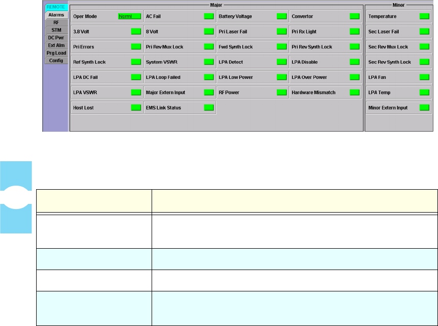
4.5.1 Remote Alarms Window
The remote Alarms window reports all major and minor alarm indicators for the
remote unit. The indicators are refreshed about once every three seconds. In
general, GREEN indicates okay, RED indicates that a major alarm exists, and
YELLOW indicates that a minor alarm exists. A major alarm causes RF functions
to be halted; a minor alarm allows RF functions to proceed as normal. Figure 71
shows the remote Alarms window.
Table 21 describes the major alarms when faulted. Table 22 describes the minor
alarms when faulted.
Figure 71. Remote Alarms Window
Table 21: Remote Major Alarms When Faulted
ALARM NAME DESCRIPTION
Oper Mode Operating mode is not “Norml.” For a description of other
modes, see Topic 4.1.4, Tools Menu, on page 60.
AC Fail There is no AC power to the remote unit.
Battery Voltage Battery voltage is low.
Converter AC converter in Spectrum Transport Module (STM) has
failed.

Screen-Based Reference Remote Displays
Element Management System (EMS) 4.0 User Manual
81
3.8 Volt The 3.8 Volt onboard supply is too low.
8 Volt The 8 Volt onboard supply is too low.
Pri Laser Fail The reverse path primary fiber laser is not sending light (no
light from remote unit to host unit).
Pri Rx Light No light is being received on the primary fiber (no light from
host unit to remote unit).
Pri Errors Multiple errors are occurring on primary fiber. Error rate has
exceeded 10–6 (one bit error per million bits).
Pri Rev Mux Lock The reverse path primary fiber phase-locked-loop is out of
lock.
Fwd Synth Lock The forward path synthesizer is out of lock.
Pri Rev Synth Lock The primary reverse path synthesizer is out of lock.
Ref Synth Lock The reference synthesizer is out of lock.
System VSWR Voltage Standing Wave Ratio measured at the duplexer is too
high.
LPA Detect The LPA is “not present” when read (physically not there).
LPA Disable LPA has been disabled due to an alarm. For instructions on
clearing this condition, position the mouse cursor on this
indicator and read the text in the pop-up window.
LPA DC Fail Linear Power Amplifier (LPA) DC power is faulted.
LPA Loop Failed LPA has an internal loop failure.
LPA Low Power RF output signal level measured in LPA is too low.
LPA Over Power RF output signal level measured in LPA is too high.
LPA VSWR Voltage Standing Wave Ratio measured in LPA is too high.
Major Extern Input Major alarm input to the remote unit is faulted.
RF Power Forward path RF power (measured in duplexer) is too low.
Table 21: Remote Major Alarms When Faulted (Continued)
ALARM NAME DESCRIPTION

Remote Displays Section 7
Element Management System (EMS) 4.0 User Manual
82
4.5.2 Remote RF Window
The remote RF (Radio Frequency) window, shown in Figure 72, contains two
subset of alarm indicators, one pertaining to the RF system in general and one
specific to the Linear Power Amplifier (LPA). In addition, this window has
dashboard displays for RF and Voltage Standing Wave Ratio (VSWR) readings
received from the LPA.
NOTE: When the LPA has been automatically disabled due to an internal LPA
alarm, it may be manually restored. For instructions, position the mouse cursor on
the LPA Disable indicator and read the instructions in the pop-up window that
appears as shown in Figure 73. In this situation, the remote Alarms window will
also display a message indicating to “Reset PA,” as shown in Figure 74.
Hardware Mismatch Host unit and remote unit are on different bands.
Host Lost Remote unit cannot communicate with host unit.
EMS Link Status EMS has not heard from the remote unit for the number of
minutes specified by the current value of the EMS Link
Timeout parameter (see Topic Topic 3.6, Setting EMS Link
Timeout, Cataloging Time, Demo Mode, on page 34).
Table 22: Remote Minor Alarms When Faulted
ALARM NAME DESCRIPTION
Temperature STM temperature is too hot.
Sec Laser Fail The reverse path secondary fiber laser is not sending light (no
light from remote unit to host unit).
Sec Rev Mux Lock The reverse path secondary fiber phase-locked-loop is out of
lock.
Sec Rev Synth Lock The secondary reverse path synthesizer is out of lock.
LPA Fan LPA fan is faulted.
LPA Temp LPA temperature is too high.
Minor Extern Alarm The minor alarm input to the remote unit is faulted.
Table 21: Remote Major Alarms When Faulted (Continued)
ALARM NAME DESCRIPTION