ADC Telecommunications DSR0805A Digivance WBDR Base Station User Manual EMSUser
ADC Telecommunications Inc Digivance WBDR Base Station EMSUser
Contents
wbdr part 5
Task-Based Reference Determining RF Signal Levels
Element Management System (EMS) 4.0 User Manual
43
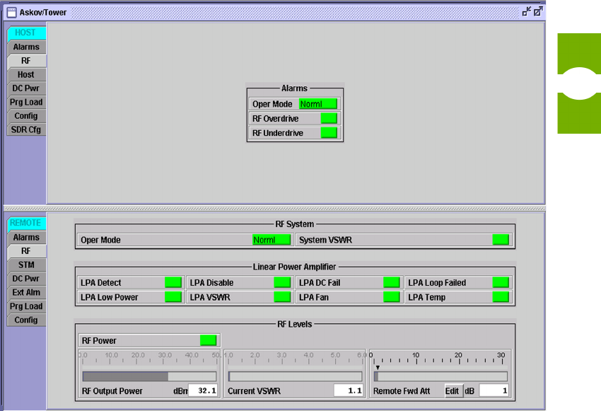
3.10 Determining RF Signal Levels
An operational host/remote pair has forward and reverse path RF signals passing
through it between the SDR BTS application and the cell phone user. The RF
signals are transported in digital format as RF spectrum data by way of fiber or
fiber-to-free-space optics links between the host unit (Host PCIx Card) and remote
unit (in both directions).
To view RF signal levels for a host/remote pair
1. From the View menu, select the site names of a host/remote pair.
2. Click on the host RF tab for the host or remote unit to view RF signal levels
and associated information for the selected unit (see Figure 33).
3. To interpret host display, see Topic 4.4.2, Host RF Window, on page 71. To
interpret remote display, see Topic 4.5.2, Remote RF Window, on page 82.
Figure 33. RF Display Example

Setting RF Forward Attenuation Section 3
Element Management System (EMS) 4.0 User Manual
44
To view RF signal levels using the NOC-NEM interface
Use the GET DATA command (see Topic 5.5.7 on page 105).
3.11 Setting RF Forward Attenuation
Using the remote unit RF window, you can adjust the current attenuation setting
for the RF forward path. This setting affects the strength of the forward path RF
analog signal transmitted from the remote unit antenna. Adjustments made in
EMS are passed to the remote unit control software, which operates a digital
attenuator. The attenuator provides an attenuation adjustment range of 0 to 31 dB,
and can be set in 1 dB increments. Any input signal with a level of –9 dBm to –40
dBm (composite) can be adjusted to the required level using the forward path
atttenuator.
NOTE: Default settings for the attenuator are the maximum, 31 dB.
NOTE: An external attenuator is required if more than 30 dB of attenuation is
required to adjust the input RF signal to the required level.
To adjust the attenuator, use the procedure below.
To enter attenuation settings for a host RF signal
1. From the View menu, select the names of a host/remote pair.
2. Click on remote RF tab to view the remote RF window (for an example, see
Figure 33 on page 43).
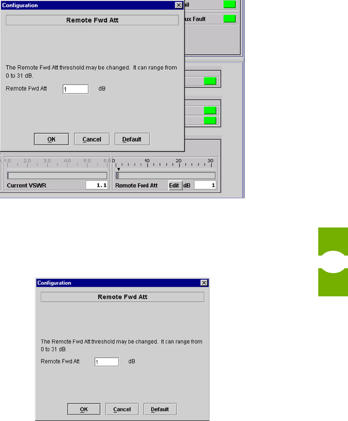
3. Click on the Edit button in the Remote Fwd Att area in the window to dis-
play the Remote Fwd Att dialog shown in Figure 34. (The Edit button to be
clicked on is in the lower right in the figure.)
Task-Based Reference Setting RF Forward Attenuation
Element Management System (EMS) 4.0 User Manual
45
Figure 34. Attenuation Area in RF Window
4. In the Remote Fwd Att dialog, key in the desired setting as shown in the
example in Figure 35.
Figure 35. Entering Remote Forward Attenuation
5. When done, click on the OK button.
To enter forward path attenuation values using NOC-NEM interface
Use the SET THRESHOLD command (see Topic 5.5.18 on page 115).
Defining RF Logical Channels Section 3
Element Management System (EMS) 4.0 User Manual
46
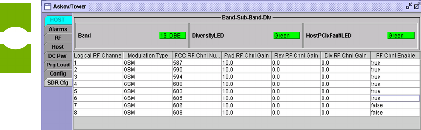
3.12 Defining RF Logical Channels
Using the host SDR Config window, shown in Figure 36, you can define a logical
RF channel and enter gain settings for each path within the channel. A logical RF
channel is a multiplex of up to eight RF voice channels. A logical RF channel
consists of a forward path, a primary reverse path, and a secondary reverse path, if
supported by the remote unit. The gain setting is simply a number that affects the
amount of gain to applied to the signal within the specified path. A negative value
results in attenuation. Each gain setting increment corresponds approximately to 1
dBm of adjustment.
To define an RF logical channel
1. From the View menu, select the names of a host/remote pair.
2. Click on the host SDR Cfg tab to display the window shown in Figure 36.
(This example shows typical a data display for logical RF channels that are
already defined.)
Figure 36. Host SDR Cfg Window
3. Determine which logical RF channel you want to enter data for. To enter val-
ues for that channel, move across in the same row in the window. The system
supports up to eight logical channels.
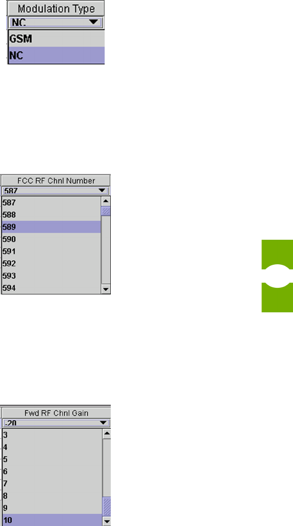
4. Click on the Modulation Type field to display a pulldown list such as shown
in Figure 37. From the list, select the modulation type of the channel being
configured.
Task-Based Reference Defining RF Logical Channels
Element Management System (EMS) 4.0 User Manual
47
Figure 37. Modulation Type
5. Click in the FCC RF Chnl Number field and from the pulldown list select an
FCC channel number as shown in the example in Figure 38. Based on modu-
lation type, band, and sub-band, EMS will list only available FCC channel
numbers.
Figure 38. FCC RF Chnl Number (Example)
6. Click in the Fwd RF Chnl Gain field to display a pulldown list such shown
in Figure 39. Select the item for the desired gain setting for the forward path.
The range of possible values is from 10 to −20 dBm. The standard value for
this field is 10.
Figure 39. Fwd RF Chnl Gain

Setting Operating Mode Section 3
Element Management System (EMS) 4.0 User Manual
48
7. Click in the Rev RF Chnl Gain field to display a pulldown list. Select the
item for the desired amount of signal gain. The range of possible values is
from 10 to −20 dBm. The standard value for this field is 0.
8. If the remote unit supports the diversity option (second reverse path), click on
the Div RF Chnl Gain field to display the pulldown list. Select the item for
the desired amount of signal gain. The range of possible values is from 10 to
−20 dBm. The standard value for this field is 0.
9. Use the last field on the right, RF Chnl Enable, to enable the channel if it will
go into immediate use. To enable the channel, click on the field to set the dis-
played value to “true.” If the channel should not be enabled at this time, let it
stay at the value “false.” When a value is changed in this field, a box appears
temporarily as shown in Figure 40.
Figure 40. Setting Channel Enable
10. When done, exit the window to proceed with other tasks if desired.
To do this same task using the NOC-NEM interface
You cannot use NOC-NEM to perform these tasks.
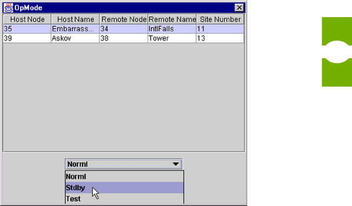
3.13 Setting Operating Mode
A host/remote pair has three user-selectable operating modes plus two modes that
happen automatically when a program file is downloaded. User-selectable modes
can be started or stopped using the OpMode window, shown in Figure 41.
Task-Based Reference Setting Operating Mode
Element Management System (EMS) 4.0 User Manual
49
To set operating modes
1. From the Tools menu, select Opmode.
2. Click on the host or remote name.
3. For a description of the modes, refer to Topic 4.1.4 on page 60. The modes are
the same for the host and remote units.
CAUTION! Care is needed to prevent damage to the system in Test Mode. Test
Mode causes the system to ignore alarms that would otherwise prevent RF sig-
nals from being transported.
4. Select an operating mode using the pull-down menu after first checking the
CAUTION statements above.
5. Stop an operating mode by selecting another mode. (In the end, select Norml
mode to return the host/remote pair to normal operation.)
Figure 41. Selecting an Operating Mode
Downloading Program Files Section 3
Element Management System (EMS) 4.0 User Manual
50
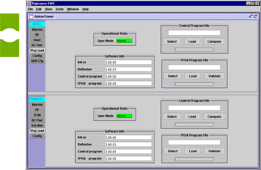
3.14 Downloading Program Files
The host and remote Prg Load windows are used to download program files to a
host/remote unit. The downloaded file may be either a control program or a Field
Programmable Gate Array (FPGA). The file is downloaded from the EMS
computer to the host/remote control board.
The loaded files have file names in the following format:
<Name><Version>.sr where
<Name> = program name
<Version> = software version number in major.minor.rev.build form
Figure 42 shows the host and remote Prg Load windows. Table 3 describes the
programs identified in the window.
Figure 42. Host and Remote Prg Load Windows

Task-Based Reference Downloading Program Files
Element Management System (EMS) 4.0 User Manual
51
To load a program file
1. Load programs from source CD-ROM to known folder on EMS computer.
2. In EMS, select names of a host/remote pair from View menu.
3. Click on the host or remote Prg Load tab (as appropriate) to view the host or
remote program load window, shown in Figure 42.
4. Click on the Select button and browse to find the program to be loaded.
5. Depending in whether the file being loaded is a control program or FPGA,
proceed as follows:
a. If loading a control program, click on the Compare button to verify that
the file you are about to load is a newer version (greater version number)
than the program than the file already loaded on the unit
b. If loading an FPGA, first check the FPGA Program field. If it contains
the word “UNKNOWN,” the unit has older type hardware with a non-
replaceable FPGA, so you cannot proceed. If the field contains a version
number, click on the Validate button to verify that the FPGA is functional
(working). When you get a message back that the FPGA is functional,
you can proceed.
Table 3: Host and Remote Programs
<NAME> DESCRIPTION CAN DOWNLOAD?
Host Unit
SDR HIniter Host Initialization Program version No
SDR HReflsh Host Reprogram Program version No
HMR HstCP Host Control Program version Yes
FPGA Program Field Programmable Gate Array version Yes
Remote Unit
SDR RInter Remote Initialization Program version No
SDR RReflsh Remote Reprogram Program version No
HMR RemCP Remote Control Program version Yes
FPGA Program Field Programmable Gate Array version Yes