Cisco Systems 102075 Cisco Aironet 802.11n Dual Band Access Points User Manual Cisco Wireless LAN Controller Configuration Guide 1
Cisco Systems Inc Cisco Aironet 802.11n Dual Band Access Points Cisco Wireless LAN Controller Configuration Guide 1
Contents
- 1. User manual
- 2. Cisco Wireless LAN Controller Configuration Guide_1
- 3. Cisco Wireless LAN Controller Configuration Guide_2
- 4. Cisco Wireless LAN Controller Configuration Guide_3
- 5. Cisco Wireless LAN Controller Configuration Guide_4
- 6. Cisco Wireless LAN Controller Configuration Guide_5
- 7. Cisco Wireless LAN Controller Configuration Guide_6
- 8. Cisco Wireless LAN Controller Configuration Guide_7
- 9. Cisco Wireless LAN Controller Configuration Guide_8
- 10. Cisco Wireless LAN Controller Configuration Guide_9
- 11. Cisco Wireless LAN Controller Configuration Guide_10
- 12. Cisco Wireless LAN Controller Configuration Guide_11
- 13. User Manual
Cisco Wireless LAN Controller Configuration Guide_1

THE SPECIFICATIONS AND INFORMATION REGARDING THE PRODUCTS IN THIS MANUAL ARE SUBJECT TO CHANGE WITHOUT NOTICE. ALL
STATEMENTS, INFORMATION, AND RECOMMENDATIONS IN THIS MANUAL ARE BELIEVED TO BE ACCURATE BUT ARE PRESENTED WITHOUT
WARRANTY OF ANY KIND, EXPRESS OR IMPLIED. USERS MUST TAKE FULL RESPONSIBILITY FOR THEIR APPLICATION OF ANY PRODUCTS.
THE SOFTWARE LICENSE AND LIMITED WARRANTY FOR THE ACCOMPANYING PRODUCT ARE SET FORTH IN THE INFORMATION PACKET THAT
SHIPPED WITH THE PRODUCT AND ARE INCORPORATED HEREIN BY THIS REFERENCE. IF YOU ARE UNABLE TO LOCATE THE SOFTWARE LICENSE
OR LIMITED WARRANTY, CONTACT YOUR CISCO REPRESENTATIVE FOR A COPY.
The Cisco implementation of TCP header compression is an adaptation of a program developed by the University of California, Berkeley (UCB) as part of UCB’s public
domain version of the UNIX operating system. All rights reserved. Copyright © 1981, Regents of the University of California.
NOTWITHSTANDING ANY OTHER WARRANTY HEREIN, ALL DOCUMENT FILES AND SOFTWARE OF THESE SUPPLIERS ARE PROVIDED “AS IS” WITH
ALL FAULTS. CISCO AND THE ABOVE-NAMED SUPPLIERS DISCLAIM ALL WARRANTIES, EXPRESSED OR IMPLIED, INCLUDING, WITHOUT
LIMITATION, THOSE OF MERCHANTABILITY, FITNESS FOR A PARTICULAR PURPOSE AND NONINFRINGEMENT OR ARISING FROM A COURSE OF
DEALING, USAGE, OR TRADE PRACTICE.
IN NO EVENT SHALL CISCO OR ITS SUPPLIERS BE LIABLE FOR ANY INDIRECT, SPECIAL, CONSEQUENTIAL, OR INCIDENTAL DAMAGES, INCLUDING,
WITHOUT LIMITATION, LOST PROFITS OR LOSS OR DAMAGE TO DATA ARISING OUT OF THE USE OR INABILITY TO USE THIS MANUAL, EVEN IF CISCO
OR ITS SUPPLIERS HAVE BEEN ADVISED OF THE POSSIBILITY OF SUCH DAMAGES.
All rights reserved.
Cisco and the Cisco Logo are trademarks of Cisco Systems, Inc. and/or its affiliates in the U.S. and other countries. A listing of Cisco's trademarks can be found at
www.cisco.com/go/trademarks. Third party trademarks mentioned are the property of their respective owners. The use of the word partner does not imply a partnership
relationship between Cisco and any other company. (1005R)
Copyright © 2011 Cisco Systems, Inc.
All rights reserved.

i
Cisco Wireless LAN Controller Configuration Guide
OL-21524-02
CONTENTS
Preface xxix
Audience xxix
Purpose xxix
Organization xxx
Conventions xxxi
Related Documentation xxxiii
Obtaining Documentation and Submitting a Service Request xxxiii
CHAPTER
1Overview 1-1
Cisco Unified Wireless Network Solution Overview 1-1
Single-Controller Deployments 1-2
Multiple-Controller Deployments 1-3
Operating System Software 1-4
Operating System Security 1-4
Cisco WLAN Solution Wired Security 1-5
Layer 2 and Layer 3 Operation 1-5
Operational Requirements 1-6
Configuration Requirements 1-6
Cisco Wireless LAN Controllers 1-6
Client Location 1-7
Controller Platforms 1-7
Cisco 2100 Series Controller 1-7
Features Not Supported 1-8
Cisco 2500 Series Controller 1-8
Cisco 4400 Series Controllers 1-9
Cisco 5500 Series Controllers 1-9
Features Not Supported 1-9
Cisco Flex 7500 Series Controller 1-10
Catalyst 6500 Series Switch Wireless Services Module 1-10
Cisco 7600 Series Router Wireless Services Module 1-11
Cisco 28/37/38xx Series Integrated Services Router 1-12
Catalyst 3750G Integrated Wireless LAN Controller Switch 1-13
Cisco UWN Solution Wired Connections 1-13

Contents
ii
Cisco Wireless LAN Controller Configuration Guide
OL-21524-02
Cisco UWN Solution WLANs 1-14
File Transfers 1-14
Power Over Ethernet 1-14
Cisco Wireless LAN Controller Memory 1-15
Cisco Wireless LAN Controller Failover Protection 1-15
Network Connections to Cisco Wireless LAN Controllers 1-16
Cisco 2100 Series Wireless LAN Controllers 1-16
Cisco 4400 Series Wireless LAN Controllers 1-17
Cisco 5500 Series Wireless LAN Controllers 1-17
CHAPTER
2Using the Web-Browser and CLI Interfaces 2-1
Using the Configuration Wizard 2-1
Connecting the Controller’s Console Port 2-1
Using the GUI Configuration Wizard 2-2
Using the CLI Configuration Wizard 2-13
Using the GUI 2-16
Guidelines for Using the GUI 2-17
Logging into the GUI 2-17
Logging Out of the GUI 2-17
Enabling Web and Secure Web Modes 2-18
Using the GUI to Enable Web and Secure Web Modes 2-18
Using the CLI to Enable Web and Secure Web Modes 2-19
Loading an Externally Generated SSL Certificate 2-20
Using the CLI 2-22
Logging into the CLI 2-23
Using a Local Serial Connection 2-23
Using a Remote Ethernet Connection 2-24
Logging Out of the CLI 2-25
Navigating the CLI 2-25
Using the AutoInstall Feature for Controllers Without a Configuration 2-26
Overview of AutoInstall 2-26
Obtaining an IP Address Through DHCP and Downloading a Configuration File from a TFTP
Server 2-26
Selecting a Configuration File 2-28
Example of AutoInstall Operation 2-29
Managing the System Date and Time 2-29
Configuring an NTP Server to Obtain the Date and Time 2-30
Configuring NTP Authentication 2-30
Using the GUI to Configure NTP Authentication 2-30

Contents
iii
Cisco Wireless LAN Controller Configuration Guide
OL-21524-02
Using the CLI to Configure NTP Authentication 2-31
Configuring the Date and Time Manually 2-31
Using the GUI to Configure the Date and Time 2-31
Using the CLI to Configure the Date and Time 2-32
Configuring Telnet and SSH Sessions 2-34
Using the GUI to Configure Telnet and SSH Sessions 2-35
Using the CLI to Configure Telnet and SSH Sessions 2-36
Enabling Wireless Connections to the GUI and CLI 2-37
CHAPTER
3Configuring Ports and Interfaces 3-1
Overview of Ports and Interfaces 3-1
Ports 3-1
Distribution System Ports 3-3
Service Port 3-5
Interfaces 3-6
Management Interface 3-7
AP-Manager Interface 3-7
Virtual Interface 3-8
Service-Port Interface 3-9
Dynamic Interface 3-9
WLANs 3-10
Configuring the Management, AP-Manager, Virtual, and Service-Port Interfaces 3-11
Using the GUI to Configure the Management, AP-Manager, Virtual, and Service-Port Interfaces 3-11
Using the CLI to Configure the Management, AP-Manager, Virtual, and Service-Port Interfaces 3-14
Using the CLI to Configure the Management Interface 3-14
Using the CLI to Configure the AP-Manager Interface 3-16
Using the CLI to Configure the Virtual Interface 3-16
Using the CLI to Configure the Service-Port Interface 3-17
Configuring Dynamic Interfaces 3-18
Using the GUI to Configure Dynamic Interfaces 3-18
Using the CLI to Configure Dynamic Interfaces 3-21
Configuring Ports 3-23
Configuring Port Mirroring 3-27
Configuring Spanning Tree Protocol 3-28
Using the GUI to Configure Spanning Tree Protocol 3-29
Using the CLI to Configure Spanning Tree Protocol 3-33
Using the Cisco 5500 Series Controller USB Console Port 3-34
Choosing Between Link Aggregation and Multiple AP-Manager Interfaces 3-36
Enabling Link Aggregation 3-36

Contents
iv
Cisco Wireless LAN Controller Configuration Guide
OL-21524-02
Link Aggregation Guidelines 3-39
Using the GUI to Enable Link Aggregation 3-40
Using the CLI to Enable Link Aggregation 3-41
Using the CLI to Verify Link Aggregation Settings 3-41
Configuring Neighbor Devices to Support Link Aggregation 3-41
Configuring Multiple AP-Manager Interfaces 3-42
Using the GUI to Create Multiple AP-Manager Interfaces 3-45
Using the CLI to Create Multiple AP-Manager Interfaces 3-47
Cisco 5500 Series Controller Example 3-47
Configuring VLAN Select 3-49
Platform Support 3-49
Using Interface Groups 3-50
Using the GUI to Create Interface Groups 3-50
Using the CLI to Create Interface Groups 3-51
Using the GUI to Add Interfaces to Interface Groups 3-51
Using the CLI to Add Interfaces to Interface Groups 3-52
Using the GUI to Add an Interface Group to a WLAN 3-52
Using the CLI to Add an Interface Group to a WLAN 3-52
Using Multicast Optimization 3-52
Using the GUI to Configure a Multicast VLAN 3-52
Using the CLI to Configure Multicast VLAN 3-53
3-53
CHAPTER
4Configuring Controller Settings 4-1
Installing and Configuring Licenses 4-2
Obtaining an Upgrade or Capacity Adder License 4-3
Installing a License 4-7
Using the GUI to Install a License 4-7
Using the CLI to Install a License 4-8
Viewing Licenses 4-9
Using the GUI to View Licenses 4-9
Using the CLI to View Licenses 4-11
Choosing the Licensed Feature Set 4-14
Using the GUI to Choose the Licensed Feature Set 4-14
Using the CLI to Choose the Licensed Feature Set 4-16
Activating an AP-Count Evaluation License 4-17
Using the GUI to Activate an AP-Count Evaluation License 4-17
Using the CLI to Activate an AP-Count Evaluation License 4-19
Rehosting a License 4-20

Contents
v
Cisco Wireless LAN Controller Configuration Guide
OL-21524-02
Using the GUI to Rehost a License 4-21
Using the CLI to Rehost a License 4-23
Transferring Licenses to a Replacement Controller after an RMA 4-25
Configuring the License Agent 4-26
Using the GUI to Configure the License Agent 4-26
Using the CLI to Configure the License Agent 4-28
Configuring 802.11 Bands 4-29
Using the GUI to Configure 802.11 Bands 4-29
Using the CLI to Configure 802.11 Bands 4-31
Configuring 802.11n Parameters 4-33
Using the GUI to Configure 802.11n Parameters 4-33
Using the CLI to Configure 802.11n Parameters 4-35
Configuring 802.11h Parameters 4-38
Using the GUI to Configure 802.11h Parameters 4-38
Using the CLI to Configure 802.11h Parameters 4-39
Configuring DHCP Proxy 4-39
Using the GUI to Configure DHCP Proxy 4-40
Using the CLI to Configure DHCP Proxy 4-40
Using the GUI to Configure a DHCP Timeout 4-41
Using the CLI to Configure DHCP Timeout 4-41
Configuring Administrator Usernames and Passwords 4-41
Configuring Usernames and Passwords 4-41
Restoring Passwords 4-42
Configuring SNMP 4-42
Changing the Default Values of SNMP Community Strings 4-43
Using the GUI to Change the SNMP Community String Default Values 4-43
Using the CLI to Change the SNMP Community String Default Values 4-44
Changing the Default Values for SNMP v3 Users 4-45
Using the GUI to Change the SNMP v3 User Default Values 4-45
Using the CLI to Change the SNMP v3 User Default Values 4-47
Configuring Aggressive Load Balancing 4-47
Client Association Limits 4-48
Client Association Limits for Lightweight Access Points 4-48
Client Association Limits for Autonomous Cisco IOS Access Points 4-48
Using the GUI to Configure Aggressive Load Balancing 4-49
Using the CLI to Configure Aggressive Load Balancing 4-50
Configuring Band Selection 4-51
Guidelines for Using the Band Selection 4-51
Using the GUI to Configure Band Selection 4-52

Contents
vi
Cisco Wireless LAN Controller Configuration Guide
OL-21524-02
Using the CLI to Configure Band Selection 4-53
Configuring Fast SSID Changing 4-54
Using the GUI to Configure Fast SSID Changing 4-54
Using the CLI to Configure Fast SSID Changing 4-54
Enabling 802.3X Flow Control 4-54
Configuring 802.3 Bridging 4-55
Using the GUI to Configure 802.3 Bridging 4-55
Using the CLI to Configure 802.3 Bridging 4-56
Configuring Multicast Mode 4-57
Understanding Multicast Mode 4-57
Guidelines for Using Multicast Mode 4-58
Using the GUI to Enable Multicast Mode 4-59
Using the GUI to View Multicast Groups 4-60
Using the CLI to Enable Multicast Mode 4-60
Using the CLI to View Multicast Groups 4-61
Using the CLI to View an Access Point’s Multicast Client Table 4-62
Configuring Client Roaming 4-62
Intra-Controller Roaming 4-62
Inter-Controller Roaming 4-62
Inter-Subnet Roaming 4-63
Voice-over-IP Telephone Roaming 4-63
CCX Layer 2 Client Roaming 4-63
Using the GUI to Configure CCX Client Roaming Parameters 4-64
Using the CLI to Configure CCX Client Roaming Parameters 4-66
Using the CLI to Obtain CCX Client Roaming Information 4-66
Using the CLI to Debug CCX Client Roaming Issues 4-67
Configuring IP-MAC Address Binding 4-67
Configuring Quality of Service 4-68
Configuring Quality of Service Profiles 4-68
Using the GUI to Configure QoS Profiles 4-68
Using the CLI to Configure QoS Profiles 4-70
Configuring Quality of Service Roles 4-71
Using the GUI to Configure QoS Roles 4-71
Using the CLI to Configure QoS Roles 4-73
Configuring Voice and Video Parameters 4-75
Call Admission Control 4-75
Bandwidth-Based CAC 4-75
Load-Based CAC 4-75
Expedited Bandwidth Requests 4-76

Contents
vii
Cisco Wireless LAN Controller Configuration Guide
OL-21524-02
U-APSD 4-77
Traffic Stream Metrics 4-77
Using the GUI to Configure Voice Parameters 4-77
Using the GUI to Configure Video Parameters 4-79
Using the GUI to View Voice and Video Settings 4-80
Using the GUI to Configure Media Parameters 4-85
Using the CLI to Configure SIP Based CAC 4-86
Using the CLI to Configure Voice Parameters 4-87
Using the CLI to Configure Video Parameters 4-88
Using the CLI to View Voice and Video Settings 4-89
Configuring Voice Prioritization Using Preferred Call Numbers 4-93
Using the GUI to Configure a Preferred Call Number 4-93
Using the CLI to Configure a Preferred Call Number 4-94
Configuring EDCA Parameters 4-94
Using the GUI to Configure EDCA Parameters 4-94
Using the CLI to Configure EDCA Parameters 4-95
Configuring the Cisco Discovery Protocol 4-96
Using the GUI to Configure the Cisco Discovery Protocol 4-99
Using the GUI to View Cisco Discovery Protocol Information 4-101
Using the CLI to Configure the Cisco Discovery Protocol 4-105
Using the CLI to View Cisco Discovery Protocol Information 4-106
Configuring Authentication for the Controller and NTP Server 4-108
Using the GUI to Configure the NTP Server for Authentication 4-108
Using the CLI to Configure the NTP Server for Authentication 4-108
Configuring RFID Tag Tracking 4-109
Using the CLI to Configure RFID Tag Tracking 4-110
Using the CLI to View RFID Tag Tracking Information 4-111
Using the CLI to Debug RFID Tag Tracking Issues 4-112
Configuring and Viewing Location Settings 4-113
Installing the Location Appliance Certificate 4-113
Synchronizing the Controller and Location Appliance 4-114
Configuring Location Settings 4-114
Viewing Location Settings 4-116
Modifying the NMSP Notification Interval for Clients, RFID Tags, and Rogues 4-118
Viewing NMSP Settings 4-118
Debugging NMSP Issues 4-121
Configuring the Supervisor 720 to Support the WiSM 4-121
General WiSM Guidelines 4-122
Configuring the Supervisor 4-122

Contents
viii
Cisco Wireless LAN Controller Configuration Guide
OL-21524-02
Using the Wireless LAN Controller Network Module 4-123
Resetting the Controller to Default Settings 4-124
Using the GUI to Reset the Controller to Default Settings 4-124
Using the CLI to Reset the Controller to Default Settings 4-124
CHAPTER
5Configuring VideoStream 5-1
Overview of the VideoStream 5-1
Guidelines for Configuring VideoStream on the Controller 5-1
Configuring VideoStream 5-2
Using the GUI to Configure the VideoStream on the Controller 5-2
Using the CLI to Configure the VideoStream to the Controller 5-8
CHAPTER
6Configuring Security Solutions 6-1
Cisco UWN Solution Security 6-1
Security Overview 6-2
Layer 1 Solutions 6-2
Layer 2 Solutions 6-2
Layer 3 Solutions 6-2
Integrated Security Solutions 6-2
Configuring RADIUS 6-3
Configuring RADIUS on the ACS 6-4
Using the GUI to Configure RADIUS 6-6
Using the CLI to Configure RADIUS 6-11
RADIUS Authentication Attributes Sent by the Access Point 6-15
RADIUS Accounting Attributes 6-18
Configuring TACACS+ 6-19
Configuring TACACS+ on the ACS 6-20
Using the GUI to Configure TACACS+ 6-24
Using the CLI to Configure TACACS+ 6-26
Viewing the TACACS+ Administration Server Logs 6-29
TACACS+ VSA 6-30
Configuring Maximum Local Database Entries 6-31
Using the GUI to Configure Maximum Local Database Entries 6-31
Using the CLI to Configure Maximum Local Database Entries 6-31
Configuring Local Network Users 6-32
Using the GUI to Configure Local Network Users 6-32
Using the CLI to Configure Local Network Users 6-34
Configuring Password Policies 6-35

Contents
ix
Cisco Wireless LAN Controller Configuration Guide
OL-21524-02
Using the GUI to Configure Password Policies 6-35
Using the CLI to Configure Password Policies 6-35
Configuring LDAP 6-36
Using the GUI to Configure LDAP 6-36
Using the CLI to Configure LDAP 6-40
Configuring Local EAP 6-42
Using the GUI to Configure Local EAP 6-43
Using the CLI to Configure Local EAP 6-49
Configuring the System for SpectraLink NetLink Telephones 6-54
Using the GUI to Enable Long Preambles 6-54
Using the CLI to Enable Long Preambles 6-55
Using the CLI to Configure Enhanced Distributed Channel Access 6-56
Configuring RADIUS NAC Support 6-56
Using the CLI to Configure RADIUS NAC Support 6-57
Using the GUI to Configure RADIUS NAC Support 6-58
Using Management over Wireless 6-58
Using the GUI to Enable Management over Wireless 6-58
Using the CLI to Enable Management over Wireless 6-59
Configuring DHCP Option 82 6-59
Using the GUI to Configure DHCP Option 82 6-60
Using the CLI to Configure DHCP Option 82 6-61
Configuring and Applying Access Control Lists 6-61
Using the GUI to Configure Access Control Lists 6-62
Using the GUI to Apply Access Control Lists 6-66
Applying an Access Control List to an Interface 6-66
Applying an Access Control List to the Controller CPU 6-67
Applying an Access Control List to a WLAN 6-68
Applying a Preauthentication Access Control List to a WLAN 6-69
Using the CLI to Configure Access Control Lists 6-70
Using the CLI to Apply Access Control Lists 6-71
Configuring Management Frame Protection 6-72
Guidelines for Using MFP 6-74
Using the GUI to Configure MFP 6-74
Using the GUI to View MFP Settings 6-76
Using the CLI to Configure MFP 6-77
Using the CLI to View MFP Settings 6-78
Using the CLI to Debug MFP Issues 6-80
Configuring Client Exclusion Policies 6-80
Using the GUI to Configure Client Exclusion Policies 6-80

Contents
x
Cisco Wireless LAN Controller Configuration Guide
OL-21524-02
Using the CLI to Configure Client Exclusion Policies 6-81
Configuring Identity Networking 6-82
Identity Networking Overview 6-82
RADIUS Attributes Used in Identity Networking 6-83
QoS-Level 6-83
ACL-Name 6-84
Interface-Name 6-84
VLAN-Tag 6-84
Tunnel Attributes 6-85
Configuring AAA Override 6-86
Updating the RADIUS Server Dictionary File for Proper QoS Values 6-86
Using the GUI to Configure AAA Override 6-88
Using the CLI to Configure AAA Override 6-88
Managing Rogue Devices 6-89
Challenges 6-89
Detecting Rogue Devices 6-89
Classifying Rogue Access Points 6-90
WCS Interaction 6-92
Configuring Rogue Detection 6-93
Using the GUI to Configure Rogue Detection 6-93
Using the CLI to Configure RLDP 6-94
Configuring Rogue Classification Rules 6-96
Using the GUI to Configure Rogue Classification Rules 6-96
Using the CLI to Configure Rogue Classification Rules 6-100
Viewing and Classifying Rogue Devices 6-102
Using the GUI to View and Classify Rogue Devices 6-102
Using the CLI to View and Classify Rogue Devices 6-107
Configuring IDS 6-112
Configuring IDS Sensors 6-112
Using the GUI to Configure IDS Sensors 6-112
Using the CLI to Configure IDS Sensors 6-114
Viewing Shunned Clients 6-115
Configuring IDS Signatures 6-117
Using the GUI to Configure IDS Signatures 6-119
Using the CLI to Configure IDS Signatures 6-124
Using the CLI to View IDS Signature Events 6-126
Configuring wIPS 6-128
Using the GUI to Configure wIPS on an Access Point 6-129
Using the CLI to Configure wIPS on an Access Point 6-129

Contents
xi
Cisco Wireless LAN Controller Configuration Guide
OL-21524-02
Viewing wIPS Information 6-130
Configuring Web Auth Proxy 6-132
Using the GUI to Configure Web Auth Proxy 6-132
Using the CLI to Configure Web Auth Proxy 6-133
Detecting Active Exploits 6-133
CHAPTER
7Configuring WLANs 7-1
WLAN Overview 7-1
Configuring WLANs 7-2
Creating WLANs 7-2
Using the GUI to Create WLANs 7-4
Using the CLI to Create WLANs 7-6
Using the GUI to Search WLANs 7-7
Configuring the Maximum Number of Clients per WLAN 7-8
Using the GUI to Configure the Maximum Number of Clients per WLAN 7-9
Using the CLI to Configure the Maximum Number of Clients per WLAN 7-9
Configuring DHCP 7-10
Internal DHCP Server 7-10
External DHCP Servers 7-10
DHCP Assignment 7-10
Security Considerations 7-11
Using the GUI to Configure DHCP 7-12
Using the CLI to Configure DHCP 7-13
Using the CLI to Debug DHCP 7-13
Configuring DHCP Scopes 7-14
Configuring MAC Filtering for WLANs 7-17
Enabling MAC Filtering 7-17
Creating a Local MAC Filter 7-18
Configuring a Timeout for Disabled Clients 7-18
Assigning WLANs to Interfaces 7-18
Configuring the DTIM Period 7-19
Using the GUI to Configure the DTIM Period 7-19
Using the CLI to Configure the DTIM Period 7-20
Configuring Peer-to-Peer Blocking 7-21
Guidelines for Using Peer-to-Peer Blocking 7-22
Using the GUI to Configure Peer-to-Peer Blocking 7-22
Using the CLI to Configure Peer-to-Peer Blocking 7-23
Configuring Layer 2 Security 7-24
Static WEP Keys 7-24

Contents
xii
Cisco Wireless LAN Controller Configuration Guide
OL-21524-02
Dynamic 802.1X Keys and Authorization 7-24
Configuring a WLAN for Both Static and Dynamic WEP 7-25
WPA1 and WPA2 7-25
CKIP 7-29
Configuring a Session Timeout 7-31
Using the GUI to Configure a Session Timeout 7-31
Using the CLI to Configure a Session Timeout 7-32
Configuring Layer 3 Security 7-32
VPN Passthrough 7-32
Web Authentication 7-33
Configuring a Fallback Policy with MAC Filtering and Web Authentication 7-35
Using the GUI to Configure a Fallback Policy with MAC Filtering and Web Authentication 7-36
Using the CLI to Configure a Fallback Policy with MAC Filtering and Web Authentication 7-37
Assigning a QoS Profile to a WLAN 7-37
Using the GUI to Assign a QoS Profile to a WLAN 7-38
Using the CLI to Assign a QoS Profile to a WLAN 7-38
Configuring QoS Enhanced BSS 7-39
Guidelines for Configuring QBSS 7-40
Additional Guidelines for Using Cisco 7921 and 7920 Wireless IP Phones 7-40
Using the GUI to Configure QBSS 7-40
Using the CLI to Configure QBSS 7-41
Configuring Media Session Snooping and Reporting 7-42
Using the GUI to Configure Media Session Snooping 7-43
Using the CLI to Configure Media Session Snooping 7-44
Configuring Reanchoring of Roaming Voice Clients 7-47
Using the GUI to Configure Reanchoring of Roaming Voice Clients 7-48
Using the CLI to Configure Reanchoring of Roaming Voice Clients 7-49
Configuring IPv6 Bridging 7-49
Guidelines for Using IPv6 Bridging 7-49
Using the GUI to Configure IPv6 Bridging 7-51
Using the CLI to Configure IPv6 Bridging 7-52
Configuring Cisco Client Extensions 7-52
Using the GUI to Configure CCX Aironet IEs 7-53
Using the GUI to View a Client’s CCX Version 7-53
Using the CLI to Configure CCX Aironet IEs 7-55
Using the CLI to View a Client’s CCX Version 7-55
Configuring Access Point Groups 7-55
Creating Access Point Groups 7-57
Configuring Web Redirect with 802.1X Authentication 7-62
Conditional Web Redirect 7-62

Contents
xiii
Cisco Wireless LAN Controller Configuration Guide
OL-21524-02
Splash Page Web Redirect 7-63
Using the GUI to Configure the RADIUS Server 7-63
Using the GUI to Configure Web Redirect 7-64
Using the CLI to Configure Web Redirect 7-65
Using the GUI to Disable the Accounting Servers per WLAN 7-66
Disabling Coverage Hole Detection per WLAN 7-67
Using the GUI to Disable Coverage Hole Detection on a WLAN 7-67
Using the CLI to Disable Coverage Hole Detection on a WLAN 7-68
Configuring NAC Out-of-Band Integration 7-68
Guidelines for Using NAC Out-of-Band Integration 7-69
Using the GUI to Configure NAC Out-of-Band Integration 7-70
Using the CLI to Configure NAC Out-of-Band Integration 7-73
Configuring Passive Client 7-74
Using the GUI to Configure Passive Client 7-75
Using the CLI to Configure Passive Client 7-78
Per-WLAN RADIUS Source Support 7-81
Configuring Per-WLAN RADIUS Source Support 7-81
Monitoring the Status of Per-WLAN RADIUS Source Support 7-82
Guidelines and Limitations 7-82
Configuring Remote LANs 7-82
Using the GUI to Configure a Remote LAN 7-83
Using the CLI to Configure a Remote LAN 7-84
CHAPTER
8Controlling Lightweight Access Points 8-1
Access Point Communication Protocols 8-2
Guidelines for Using CAPWAP 8-2
Configuring Data Encryption 8-2
Upgrading or Downgrading DTLS Images for Cisco 5500 Series Controllers 8-4
Using the GUI to Configure Data Encryption 8-4
Using the CLI to Configure Data Encryption 8-5
Viewing CAPWAP MTU Information 8-6
Debugging CAPWAP 8-7
Controller Discovery Process 8-7
Verifying that Access Points Join the Controller 8-9
Using the GUI to Verify that Access Points Join the Controller 8-9
Using the CLI to Verify that Access Points Join the Controller 8-9
All APs 8-9
Using the GUI to Search the AP Filter 8-10
All APs > Details 8-13

Contents
xiv
Cisco Wireless LAN Controller Configuration Guide
OL-21524-02
Using the GUI to Monitor the Interface Details 8-28
Using the GUI to Search Access Point Radios 8-31
Configuring Global Credentials for Access Points 8-33
Using the GUI to Configure Global Credentials for Access Points 8-33
Using the CLI to Configure Global Credentials for Access Points 8-35
Configuring Authentication for Access Points 8-37
Using the GUI to Configure Authentication for Access Points 8-38
Using the CLI to Configure Authentication for Access Points 8-39
Configuring the Switch for Authentication 8-41
Embedded Access Points 8-41
Autonomous Access Points Converted to Lightweight Mode 8-43
Guidelines for Using Access Points Converted to Lightweight Mode 8-44
Reverting from Lightweight Mode to Autonomous Mode 8-44
Using a Controller to Return to a Previous Release 8-44
Using the MODE Button and a TFTP Server to Return to a Previous Release 8-45
Authorizing Access Points 8-45
Authorizing Access Points Using SSCs 8-45
Authorizing Access Points Using MICs 8-46
Authorizing Access Points Using LSCs 8-46
Using the GUI to Authorize Access Points 8-50
Using the CLI to Authorize Access Points 8-51
Using DHCP Option 43 and DHCP Option 60 8-52
Troubleshooting the Access Point Join Process 8-53
Using the CLI to Configure the Syslog Server for Access Points 8-55
Viewing Access Point Join Information 8-55
Using a Controller to Send Debug Commands to Access Points Converted to Lightweight Mode 8-60
Understanding How Converted Access Points Send Crash Information to the Controller 8-60
Understanding How Converted Access Points Send Radio Core Dumps to the Controller 8-60
Using the CLI to Retrieve Radio Core Dumps 8-61
Using the GUI to Upload Radio Core Dumps 8-61
Using the CLI to Upload Radio Core Dumps 8-62
Uploading Memory Core Dumps from Converted Access Points 8-63
Using the GUI to Upload Access Point Core Dumps 8-63
Using the CLI to Upload Access Point Core Dumps 8-63
Viewing the AP Crash Log Information 8-64
Using the GUI to View the AP Crash Log information 8-64
Using the CLI to View the AP Crash Log information 8-65
Displaying MAC Addresses for Converted Access Points 8-65
Disabling the Reset Button on Access Points Converted to Lightweight Mode 8-66

Contents
xv
Cisco Wireless LAN Controller Configuration Guide
OL-21524-02
Configuring a Static IP Address on a Lightweight Access Point 8-66
Using the GUI to Configure a Static IP Address 8-66
Using the CLI to Configure a Static IP Address 8-67
Supporting Oversized Access Point Images 8-68
OfficeExtend Access Points 8-69
OEAP 600 Series Access Points 8-70
Supported Controller Platforms 8-70
OEAP in Local Mode 8-70
Supported WLAN Settings for 600 Series OfficeExtend Access Point 8-71
WLAN Security Settings for the 600 Series OfficeExtend Access Point 8-72
Authentication Settings 8-76
Supported User Count on 600 Series OfficeExtend Access Point 8-76
Remote LAN Settings 8-77
Channel Management and Settings 8-78
Additional Caveats 8-79
Implementing Security 8-79
Licensing for an OfficeExtend Access Point 8-80
Configuring OfficeExtend Access Points 8-80
Using the GUI to Configure OfficeExtend Access Points 8-80
Using the CLI to Configure OfficeExtend Access Points 8-83
Configuring a Personal SSID on an OfficeExtend Access Point 8-85
Viewing OfficeExtend Access Point Statistics 8-87
Troubleshooting OfficeExtend Access Points 8-88
Cisco Workgroup Bridges 8-88
Guidelines for Using WGBs 8-88
Sample WGB Configuration 8-90
Using the GUI to View the Status of Workgroup Bridges 8-91
Using the CLI to View the Status of Workgroup Bridges 8-93
Using the CLI to Debug WGB Issues 8-94
Non-Cisco Workgroup Bridges 8-94
Notes About Some non-Cisco WGBs 8-95
Configuring Backup Controllers 8-95
Using the GUI to Configure Backup Controllers 8-96
Using the CLI to Configure Backup Controllers 8-99
Configuring Failover Priority for Access Points 8-101
Using the GUI to Configure Failover Priority for Access Points 8-101
Using the CLI to Configure Failover Priority for Access Points 8-102
Using the CLI to View Failover Priority Settings 8-103
Configuring Access Point Retransmission Interval and Retry Count 8-103

Contents
xvi
Cisco Wireless LAN Controller Configuration Guide
OL-21524-02
Using the GUI to Configure the Access Point Retransmission Interval and Retry Count 8-104
Using the CLI to Configure the Access Point Retransmission Interval and Retry Count 8-105
Configuring Country Codes 8-106
Guidelines for Configuring Multiple Country Codes 8-106
Using the GUI to Configure Country Codes 8-107
Using the CLI to Configure Country Codes 8-109
Migrating Access Points from the -J Regulatory Domain to the -U Regulatory Domain 8-111
Guidelines for Migration 8-112
Using the GUI to Migrate Access Points to the -U Regulatory Domain 8-113
Using the W56 Band in Japan 8-114
Dynamic Frequency Selection 8-115
Optimizing RFID Tracking on Access Points 8-116
Using the GUI to Optimize RFID Tracking on Access Points 8-116
Using the CLI to Optimize RFID Tracking on Access Points 8-118
Using the CLI to Configure Probe Request Forwarding 8-119
Retrieving the Unique Device Identifier on Controllers and Access Points 8-120
Using the GUI to Retrieve the Unique Device Identifier on Controllers and Access Points 8-120
Using the CLI to Retrieve the Unique Device Identifier on Controllers and Access Points 8-121
Performing a Link Test 8-121
Using the GUI to Perform a Link Test 8-122
Using the CLI to Perform a Link Test 8-124
Configuring Link Latency 8-124
Using the GUI to Configure Link Latency 8-125
Using the CLI to Configure Link Latency 8-126
Configuring the TCP MSS 8-127
Using the CLI to Configure TCP MSS 8-127
Configuring Power over Ethernet 8-128
Using the GUI to Configure Power over Ethernet 8-129
Using the CLI to Configure Power over Ethernet 8-131
Configuring Flashing LEDs 8-132
Viewing Clients 8-133
Using the GUI to View Clients 8-133
Using the CLI to View Clients 8-137
CHAPTER
9Controlling Mesh Access Points 9-1
Cisco Aironet Mesh Access Points 9-1
Access Point Roles 9-2
Network Access 9-3

Contents
xvii
Cisco Wireless LAN Controller Configuration Guide
OL-21524-02
Network Segmentation 9-4
Cisco Indoor Mesh Access Points 9-4
Cisco Outdoor Mesh Access Points 9-4
Mesh Deployment Modes 9-5
Wireless Mesh Network 9-5
Wireless Backhaul 9-6
Point-to-Multipoint Wireless Bridging 9-7
Point-to-Point Wireless Bridging 9-7
Architecture Overview 9-12
CAPWAP 9-12
Cisco Adaptive Wireless Path Protocol Wireless Mesh Routing 9-12
Mesh Neighbors, Parents, and Children 9-12
Wireless Mesh Constraints 9-13
Wireless Backhaul Data Rate 9-13
ClientLink Technology 9-16
Using the GUI to Configure ClientLink 9-17
Using the CLI to Configure ClientLink 9-19
Commands Related to ClientLink 9-20
Controller Planning 9-21
Adding Mesh Access Points to the Mesh Network 9-23
Adding MAC Addresses of Mesh Access Points to MAC Filter 9-24
Adding the MAC Address of the Mesh Access Point to the Controller Filter List Using the
GUI 9-24
Adding the MAC Address of the Mesh Access Point to the Controller Filter List Using the
CLI 9-25
Defining Mesh Access Point Role 9-26
Configuring the AP Role Using the GUI 9-26
Verifying Layer 3 Configuration 9-27
Configuring Multiple Controllers Using DHCP 43 and DHCP 60 9-27
Configuring Backup Controllers 9-28
Configuring Backup Controllers Using the GUI 9-29
Configuring Backup Controllers Using the CLI 9-31
Configuring External Authentication and Authorization Using a RADIUS Server 9-33
Configuring RADIUS Servers 9-33
Adding a Username to a RADIUS Server 9-34
Enabling External Authentication of Mesh Access Points Using the GUI 9-34
Enable External Authentication of Mesh Access Points Using the CLI 9-35
View Security Statistics Using the CLI 9-35
Configuring Global Mesh Parameters 9-35
Configuring Global Mesh Parameters Using the GUI 9-36

Contents
xviii
Cisco Wireless LAN Controller Configuration Guide
OL-21524-02
Configuring Global Mesh Parameters Using the CLI 9-40
Viewing Global Mesh Parameter Settings Using the CLI 9-41
Universal Client Access 9-42
Configuring Universal Client Access using the GUI 9-42
Configuring Universal Client Access using the CLI 9-43
Universal Client Access on Serial Backhaul Access Points 9-43
Configuring Extended Universal Access Using the GUI 9-44
Configuring Extended Universal Access Using the CLI 9-46
Configuring Extended Universal Access from the Wireless Control System (WCS) 9-47
Configuring Local Mesh Parameters 9-47
Configuring Wireless Backhaul Data Rate 9-48
Configuring Ethernet Bridging 9-52
Enabling Ethernet Bridging Using the GUI 9-53
Configuring Bridge Group Names 9-54
Configuring BGN Using the CLI 9-54
Verifying BGN Using the GUI 9-55
Configuring Public Safety Band Settings 9-56
Configuring Interoperability with Cisco 3200 9-57
Enabling AP1522 to Associate with Cisco 3200 Using the GUI 9-58
Enabling 1522 and 1524PS Association with Cisco 3200 Using the CLI 9-59
Configuring Power and Channel Settings 9-60
Configuring Antenna Gain 9-63
Configuring Antenna Gain Using the GUI 9-63
Configuring Antenna Gain Using the CLI 9-64
Backhaul Channel Deselection on Serial Backhaul Access Point 9-64
Configuring Backhaul Channel Deselection Using the GUI 9-65
Configuring Backhaul Channel Deselection Using the CLI 9-65
Backhaul Channel Deselection Guidelines 9-68
Configuring Dynamic Channel Assignment 9-69
Configuring Advanced Features 9-72
Using the 2.4-GHz Radio for Backhaul 9-72
Changing the Backhaul from 5 GHz to 2.4 GHz 9-73
Changing the Backhaul from 2.4 GHz to 5 GHz 9-74
Verifying the Current Backhaul in Use 9-74
Configuring Ethernet VLAN Tagging 9-74
Ethernet Port Notes 9-75
Ethernet VLAN Tagging Guidelines 9-76
VLAN Registration 9-78
Enabling Ethernet VLAN Tagging Using the GUI 9-78
Configuring Ethernet VLAN Tagging Using the CLI 9-80

Contents
xix
Cisco Wireless LAN Controller Configuration Guide
OL-21524-02
Viewing Ethernet VLAN Tagging Configuration Details Using the CLI 9-81
Workgroup Bridge Interoperability with Mesh Infrastructure 9-82
Configuring Workgroup Bridges 9-84
Supported Workgroup Bridge Modes and Capacities 9-84
Guidelines for Configuration 9-86
Configuration Example 9-87
WGB Association Check 9-88
Link Test Result 9-89
WGB Wired/Wireless Client 9-91
Client Roaming 9-92
WGB Roaming Guidelines 9-92
Configuration Example 9-93
Troubleshooting Tips 9-93
Configuring Voice Parameters in Indoor Mesh Networks 9-94
CAC 9-94
QoS and DSCP Marking 9-94
Encapsulations 9-95
Queuing on the Mesh Access Point 9-96
Bridging Backhaul Packets 9-98
Bridging Packets from and to a LAN 9-99
Guidelines For Using Voice on the Mesh Network 9-99
Voice Call Support in a Mesh Network 9-100
Viewing the Voice Details for Mesh Networks Using the CLI 9-101
Enabling Mesh Multicast Containment for Video 9-104
Enabling Multicast on the Mesh Network Using the CLI 9-105
IGMP Snooping 9-105
Locally Significant Certificates for Mesh APs 9-106
Guidelines for Configuration 9-106
Differences Between LSCs for Mesh APs and Normal APs 9-107
Certificate Verification Process in LSC AP 9-107
Configuring an LSC Using the CLI 9-107
LSC-Related Commands 9-108
Controller CLI show Commands 9-110
Controller GUI Security Settings 9-110
Deployment Guidelines 9-112
Slot Bias Options 9-112
Disabling Slot Bias 9-112
Commands Related to Slot Bias 9-113
Preferred Parent Selection 9-114
Preferred Parent Selection Criteria 9-114

Contents
xx
Cisco Wireless LAN Controller Configuration Guide
OL-21524-02
Configuring a Preferred Parent 9-114
Co-Channel Interference 9-116
Viewing Mesh Statistics for a Mesh Access Point 9-116
Viewing Mesh Statistics for a Mesh Access Point Using the GUI 9-116
Viewing Mesh Statistics for an Mesh Access Point Using the CLI 9-120
Viewing Neighbor Statistics for a Mesh Access Point 9-121
Viewing Neighbor Statistics for a Mesh Access Point Using the GUI 9-121
Viewing the Neighbor Statistics for a Mesh Access Point using the CLI 9-123
Converting Indoor Access Points to Mesh Access Points 9-124
Changing MAP and RAP Roles for Indoor Mesh Access Points 9-125
Using the GUI to Change MAP and RAP Roles for Indoor Mesh Access Points 9-125
Using the CLI to Change MAP and RAP Roles for Indoor Mesh Access Points 9-125
Converting Indoor Mesh Access Points to Nonmesh Lightweight Access Points (1130AG, 1240AG) 9-126
Configuring Mesh Access Points to Operate with Cisco 3200 Series Mobile Access Routers 9-127
Configuration Guidelines 9-127
Using the GUI to Enable Mesh Access Points to Operate with Cisco 3200 Series Mobile Access
Routers 9-128
Using the CLI to Enable Mesh Access Points to Operate with Cisco 3200 Series Mobile Access
Routers 9-129
CHAPTER
10 Managing Controller Software and Configurations 10-1
Upgrading the Controller Software 10-1
Guidelines for Upgrading Controller Software 10-2
Guidelines for Upgrading to Controller Software 6.0 in Mesh Networks 10-3
Upgrade Compatibility Matrix 10-3
Using the GUI to Upgrade Controller Software 10-5
Using the CLI to Upgrade Controller Software 10-8
Predownloading an Image to an Access Point 10-11
Access Point Predownload Process 10-11
Guidelines and Limitations for Predownloading Images 10-12
Using the GUI to Predownload an Image to an Access Point 10-12
Using the CLI to Predownload an Image to Access Points 10-13
Transferring Files to and from a Controller 10-15
Downloading a Login Banner File 10-15
Using the GUI to Download a Login Banner File 10-16
Using the CLI to Download a Login Banner File 10-17
Using the GUI to Clear the Login Banner 10-18
Downloading Device Certificates 10-19
Using the GUI to Download Device Certificates 10-20

Contents
xxi
Cisco Wireless LAN Controller Configuration Guide
OL-21524-02
Using the CLI to Download Device Certificates 10-21
Downloading CA Certificates 10-22
Using the GUI to Download CA Certificates 10-22
Using the CLI to Download CA Certificates 10-23
Uploading PACs 10-25
Using the GUI to Upload PACs 10-25
Using the CLI to Upload PACs 10-26
Uploading and Downloading Configuration Files 10-27
Uploading Configuration Files 10-28
Downloading Configuration Files 10-30
Saving Configurations 10-33
Editing Configuration Files 10-33
Clearing the Controller Configuration 10-34
Erasing the Controller Configuration 10-34
Resetting the Controller 10-35
CHAPTER
11 Managing User Accounts 11-1
Creating Guest User Accounts 11-1
Creating a Lobby Ambassador Account 11-1
Using the GUI to Create a Lobby Ambassador Account 11-1
Using the CLI to Create a Lobby Ambassador Account 11-3
Creating Guest User Accounts as a Lobby Ambassador 11-3
Viewing Guest User Accounts 11-5
Using the GUI to View Guest Accounts 11-5
Using the CLI to View Guest Accounts 11-6
Obtaining a Web Authentication Certificate 11-6
Support for Chained Certificate 11-6
Using the GUI to Obtain a Web Authentication Certificate 11-6
Using the CLI to Obtain a Web Authentication Certificate 11-8
Web Authentication Process 11-9
Choosing the Web Authentication Login Page 11-11
Choosing the Default Web Authentication Login Page 11-12
Using the GUI to Choose the Default Web Authentication Login Page 11-12
Using the CLI to Choose the Default Web Authentication Login Page 11-13
Modified Default Web Authentication Login Page Example 11-15
Creating a Customized Web Authentication Login Page 11-16
Using a Customized Web Authentication Login Page from an External Web Server 11-19
Using the GUI to Choose a Customized Web Authentication Login Page from an External Web
Server 11-19

Contents
xxii
Cisco Wireless LAN Controller Configuration Guide
OL-21524-02
Using the CLI to Choose a Customized Web Authentication Login Page from an External Web
Server 11-20
Downloading a Customized Web Authentication Login Page 11-20
Using the GUI to Download a Customized Web Authentication Login Page 11-21
Using the CLI to Download a Customized Web Authentication Login Page 11-22
Customized Web Authentication Login Page Example 11-23
Using the CLI to Verify the Web Authentication Login Page Settings 11-23
Assigning Login, Login Failure, and Logout Pages per WLAN 11-24
Using the GUI to Assign Login, Login Failure, and Logout Pages per WLAN 11-24
Using the CLI to Assign Login, Login Failure, and Logout Pages per WLAN 11-25
Configuring Wired Guest Access 11-26
Configuration Overview 11-28
Wired Guest Access Guidelines 11-28
Using the GUI to Configure Wired Guest Access 11-29
Using the CLI to Configure Wired Guest Access 11-32
CHAPTER
12 Configuring Cisco CleanAir 12-1
Overview of Cisco CleanAir 12-1
Role of the Controller 12-1
Benefits 12-2
Types of Interferences 12-2
Supported Access Point Modes 12-3
Guidelines 12-4
Configuring Cisco CleanAir on the Controller 12-5
Using the GUI to Configure Cisco CleanAir on the Controller 12-5
Using the CLI to Configure Cisco CleanAir on the Controller 12-8
Configuring Cisco CleanAir on an Access Point 12-11
Using the GUI to Configure Cisco CleanAir on an Access Point 12-11
Using the CLI to Configure Cisco CleanAir on an Access Point 12-13
Monitoring the Interference Devices 12-14
Using GUI to Monitor the Interference Device 12-14
Using the CLI to Monitor the Interference Device 12-16
Monitoring the Air Quality of Radio Bands 12-18
Using the GUI to Monitor the Air Quality of Radio Bands 12-18
Using the CLI to Monitor the Air Quality of Radio Bands 12-19
Using the GUI to Monitor the Worst Air Quality of Radio Bands 12-19
Using the CLI to Monitor the Worst Air Quality of Radio Bands 12-20
Configuring a Spectrum Expert Connection 12-23

Contents
xxiii
Cisco Wireless LAN Controller Configuration Guide
OL-21524-02
CHAPTER
13 Configuring Radio Resource Management 13-1
Overview of Radio Resource Management 13-1
Radio Resource Monitoring 13-2
Transmit Power Control 13-2
Dynamic Channel Assignment 13-3
Coverage Hole Detection and Correction 13-4
RRM Benefits 13-5
Overview of RF Groups 13-5
RF Grouping Support for Controllers and Access Points 13-5
RF Group Leader 13-6
RF Group Name 13-7
Configuring an RF Group 13-7
Using the GUI to Configure an RF Group Name 13-8
Using the CLI to Configure an RF Group Name 13-8
Viewing the RF Group Status 13-9
Using the GUI to View RF Group Status 13-9
Using the CLI to View RF Group Status 13-10
Configuring RRM 13-10
Configuring RRM 13-11
Using the GUI to Configure RF Group Mode 13-11
Using the CLI to Configure the RF Group Mode 13-12
Using the GUI to Configure Transmit Power Control 13-13
Off-Channel Scanning Defer 13-14
Using the GUI to Configure Off-Channel Scanning Defer for a WLAN 13-14
Using the CLI to Configure Off Channel Scanning Defer for a WLAN 13-15
Using the GUI to Configure Dynamic Channel Assignment 13-16
Using the GUI to Configure Coverage Hole Detection 13-20
Using the GUI to Configure RRM Profile Thresholds, Monitoring Channels, and Monitor
Intervals 13-22
Using the CLI to Configure RRM 13-24
Using the CLI to View RRM Settings 13-28
Using the CLI to Debug RRM Issues 13-30
RRM Neighbor Discovery Packet 13-31
Important Notes about RRM NDP and RF Grouping 13-31
Configuring RRM NDP Using the CLI 13-31
Overriding RRM 13-32
Statically Assigning Channel and Transmit Power Settings to Access Point Radios 13-32
Using the GUI to Statically Assign Channel and Transmit Power Settings 13-32
Using the CLI to Statically Assign Channel and Transmit Power Settings 13-37

Contents
xxiv
Cisco Wireless LAN Controller Configuration Guide
OL-21524-02
Disabling Dynamic Channel and Power Assignment Globally for a Controller 13-39
Using the GUI to Disable Dynamic Channel and Power Assignment 13-39
Using the CLI to Disable Dynamic Channel and Power Assignment 13-40
Enabling Rogue Access Point Detection in RF Groups 13-40
Using the GUI to Enable Rogue Access Point Detection in RF Groups 13-41
Using the CLI to Enable Rogue Access Point Detection in RF Groups 13-42
Configuring Beamforming 13-43
Guidelines for Using Beamforming 13-44
Using the GUI to Configure Beamforming 13-44
Using the CLI to Configure Beamforming 13-46
Configuring CCX Radio Management Features 13-48
Radio Measurement Requests 13-48
Location Calibration 13-49
Using the GUI to Configure CCX Radio Management 13-49
Using the CLI to Configure CCX Radio Management 13-50
Using the CLI to Obtain CCX Radio Management Information 13-50
Using the CLI to Debug CCX Radio Management Issues 13-52
CHAPTER
14 Configuring Mobility Groups 14-1
Overview of Mobility 14-1
Overview of Mobility Groups 14-4
Determining When to Include Controllers in a Mobility Group 14-7
Messaging Among Mobility Groups 14-7
Using Mobility Groups with NAT Devices 14-8
Configuring Mobility Groups 14-9
Prerequisites 14-9
Using the GUI to Configure Mobility Groups 14-11
Using the CLI to Configure Mobility Groups 14-15
Viewing Mobility Group Statistics 14-17
Using the GUI to View Mobility Group Statistics 14-17
Using the CLI to View Mobility Group Statistics 14-20
Configuring Auto-Anchor Mobility 14-20
Guidelines for Using Auto-Anchor Mobility 14-22
Using the GUI to Configure Auto-Anchor Mobility 14-22
Using the CLI to Configure Auto-Anchor Mobility 14-24
WLAN Mobility Security Values 14-26
Using Symmetric Mobility Tunneling 14-26
Running Mobility Ping Tests 14-29

Contents
xxv
Cisco Wireless LAN Controller Configuration Guide
OL-21524-02
Configuring Dynamic Anchoring for Clients with Static IP Addresses 14-30
How Dynamic Anchoring of Static IP Clients Works 14-30
Using the GUI to Configure Dynamic Anchoring of Static IP Clients 14-31
Using the CLI to Configure Dynamic Anchoring of Static IP Clients 14-31
Configuring Foreign Mappings 14-31
Using the GUI to Configure Foreign MAC Mapping 14-32
Using the CLI to Configure Foreign Controller MAC Mapping 14-32
CHAPTER
15 Configuring Hybrid REAP 15-1
Overview of Hybrid REAP 15-1
Hybrid-REAP Authentication Process 15-2
Hybrid-REAP Guidelines 15-6
Configuring Hybrid REAP 15-7
Configuring the Switch at the Remote Site 15-7
Configuring the Controller for Hybrid REAP 15-8
Using the GUI to Configure the Controller for Hybrid REAP 15-8
Using the CLI to Configure the Controller for Hybrid REAP 15-13
Configuring an Access Point for Hybrid REAP 15-13
Using the GUI to Configure an Access Point for Hybrid REAP 15-13
Using the CLI to Configure an Access Point for Hybrid REAP 15-16
Using the GUI to Configure an Access Point for Local Authentication on a WLAN 15-17
Using the CLI to Configure an Access Point for Local Authentication on a WLAN 15-18
Connecting Client Devices to the WLANs 15-18
Configuring Hybrid-REAP Groups 15-19
Hybrid-REAP Groups and Backup RADIUS Servers 15-20
Hybrid-REAP Groups and CCKM 15-20
Hybrid-REAP Groups and OKC 15-20
Hybrid-REAP Groups and Local Authentication 15-20
Using the GUI to Configure Hybrid-REAP Groups 15-21
Using the CLI to Configure Hybrid-REAP Groups 15-25
APPENDIX
ASafety Considerations and Translated Safety Warnings A-1
Safety Considerations A-1
Warning Definition A-2
Class 1 Laser Product Warning A-5
Ground Conductor Warning A-7
Chassis Warning for Rack-Mounting and Servicing A-9
Battery Handling Warning A-18

Contents
xxvi
Cisco Wireless LAN Controller Configuration Guide
OL-21524-02
Equipment Installation Warning A-20
More Than One Power Supply Warning for Cisco 5500 and 4400 Series Controllers A-23
APPENDIX
BDeclarations of Conformity and Regulatory Information B-1
Guidelines for Operating Controllers in Japan B-1
VCCI Class A Warning for Cisco 5500 Series Controllers and 4400 Series Controllers in
Japan B-1
VCCI Class B Warning for Cisco 2100 Series Controller in Japan B-2
Power Cable and AC Adapter Warning for Japan B-2
Declaration of Conformity Statements B-2
FCC Statement for Cisco 5500 Series Wireless LAN Controllers B-3
FCC Statement for Cisco 4400 Series Wireless LAN Controllers B-3
FCC Statement for Cisco 2100 Series Wireless LAN Controllers B-3
APPENDIX
CEnd User License and Warranty C-1
End User License Agreement C-1
Limited Warranty C-4
Disclaimer of Warranty C-5
General Terms Applicable to the Limited Warranty Statement and End User License Agreement C-5
Notices and Disclaimers C-6
Notices C-6
OpenSSL/Open SSL Project C-6
Disclaimers C-8
APPENDIX
DTroubleshooting D-1
Interpreting LEDs D-1
Interpreting Controller LEDs D-1
Interpreting Lightweight Access Point LEDs D-2
System Messages D-2
Viewing System Resources D-5
Using the CLI to Troubleshoot Problems D-6
Configuring System and Message Logging D-8
Using the GUI to Configure System and Message Logging D-8
Using the GUI to View Message Logs D-10
Using the CLI to Configure System and Message Logging D-11
Using the CLI to View System and Message Logs D-14
Viewing Access Point Event Logs D-15
Uploading Logs and Crash Files D-15

Contents
xxvii
Cisco Wireless LAN Controller Configuration Guide
OL-21524-02
Using the GUI to Upload Logs and Crash Files D-16
Using the CLI to Upload Logs and Crash Files D-17
Uploading Core Dumps from the Controller D-18
Configuring the Controller to Automatically Upload Core Dumps to an FTP Server D-18
Using the GUI to Configure the Controller to Automatically Upload Core Dumps to an FTP
Server D-18
Using the CLI to Configure the Controller to Automatically Upload Core Dumps to an FTP
Server D-19
Uploading Core Dumps from Controller to a TFTP or FTP Server D-20
Uploading Packet Capture Files D-21
Using the GUI to Upload Packet Capture Files D-22
Using the CLI to Upload Packet Capture Files D-23
Monitoring Memory Leaks D-24
Troubleshooting CCXv5 Client Devices D-25
Diagnostic Channel D-25
Client Reporting D-26
Roaming and Real-Time Diagnostics D-26
Using the GUI to Configure the Diagnostic Channel D-26
Using the CLI to Configure the Diagnostic Channel D-27
Using the GUI to Configure Client Reporting D-31
Using the CLI to Configure Client Reporting D-34
Using the CLI to Configure Roaming and Real-Time Diagnostics D-37
Using the Debug Facility D-40
Configuring Wireless Sniffing D-44
Prerequisites for Wireless Sniffing D-45
Using the GUI to Configure Sniffing on an Access Point D-45
Using the CLI to Configure Sniffing on an Access Point D-47
Troubleshooting Access Points Using Telnet or SSH D-48
Using the GUI to Troubleshoot Access Points Using Telnet or SSH D-49
Using the CLI to Troubleshoot Access Points Using Telnet or SSH D-49
Debugging the Access Point Monitor Service D-50
Using the CLI to Debug Access Point Monitor Service Issues D-50
Troubleshooting OfficeExtend Access Points D-51
Interpreting OfficeExtend LEDs D-51
Positioning OfficeExtend Access Points for Optimal RF Coverage D-51
Troubleshooting Common Problems D-51
APPENDIX
ELogical Connectivity Diagrams E-1
Cisco WiSM E-1

Contents
xxviii
Cisco Wireless LAN Controller Configuration Guide
OL-21524-02
Cisco 28/37/38xx Integrated Services Router E-3
Catalyst 3750G Integrated Wireless LAN Controller Switch E-4
Login Command E-5
Show Commands E-5
Debug Commands E-6
Reset Commands E-7

xxix
Cisco Wireless LAN Controller Configuration Guide
OL-21524-02
Preface
This preface describes the audience, organization, and conventions of the Cisco Wireless LAN Controller
Configuration Guide, Release 7.0.116.0. It also provides information on how to obtain other
documentation. This chapter includes the following sections:
• Audience, page xxix
• Purpose, page xxix
• Organization, page xxx
• Conventions, page xxxi
• Related Documentation, page xxxiii
• Obtaining Documentation and Submitting a Service Request, page xxxiii
Audience
This publication is for experienced network administrators who configure and maintain Cisco wireless
LAN controllers and Cisco lightweight access points.
Purpose
This guide provides the information you need to set up and configure wireless LAN controllers.
Note This version of the Cisco Wireless LAN Controller Configuration Guide pertains specifically to
controller software release 7.0.116.0. If you are using an earlier version of software, you will notice
differences in features, functionality, and GUI pages.

xxx
Cisco Wireless LAN Controller Configuration Guide
OL-21524-02
Preface
Organization
This guide is organized into these chapters:
Chapter Title Description
Chapter 1, “Overview” Provides an overview of the network roles and features of wireless LAN
controllers.
Chapter 2, “Using the
Web-Browser and CLI
Interfaces”
Describes how to initially configure and log into the controller.
Chapter 3, “Configuring
Ports and Interfaces”
Describes the controller’s physical ports and interfaces and provides
instructions for configuring them.
Chapter 4, “Configuring
Controller Settings”
Describes how to configure settings on the controllers.
Chapter 5, “Configuring
VideoStream”
Describes how to configure VideoStream settings on the controller.
Chapter 6, “Configuring
Security Solutions”
Describes application-specific solutions for wireless LANs.
Chapter 7, “Configuring
WLANs”
Describes how to configure wireless LANs and SSIDs on your system.
Chapter 8, “Controlling
Lightweight Access
Points”
Explains how to connect lightweight access points to the controller and
manage access point settings.
Chapter 9, “Controlling
Mesh Access Points”
Explains how to connect mesh access points to the controller and manage
access point settings.
Chapter 10, “Managing
Controller Software and
Configurations”
Describes how to upgrade and manage controller software and
configurations.
Chapter 11, “Managing
User Accounts”
Explains how to create and manage guest user accounts, describes the
web authentication process, and provides instructions for customizing the
web authentication login.
Chapter 13, “Configuring
Radio Resource
Management”
Describes radio resource management (RRM) and explains how to
configure it on the controllers.
Chapter 12, “Configuring
Cisco CleanAir”
Describes how to configure Cisco CleanAir functionality on the
controller and lightweight access points.
Chapter 14, “Configuring
Mobility Groups”
Describes mobility groups and explains how to configure them on the
controllers.
Chapter 15, “Configuring
Hybrid REAP”
Describes hybrid REAP and explains how to configure this feature on
controllers and access points.
Appendix A, “Safety
Considerations and
Translated Safety
Warnings”
Lists safety considerations and translations of the safety warnings that
apply to the Cisco Unified Wireless Network solution products.

xxxi
Cisco Wireless LAN Controller Configuration Guide
OL-21524-02
Preface
Conventions
This document uses the following conventions:
Note Means reader take note.
Tip Means the following information will help you solve a problem.
Appendix B,
“Declarations of
Conformity and
Regulatory Information”
Provides declarations of conformity and regulatory information for the
products in the Cisco Unified Wireless Network solution.
Appendix C, “End User
License and Warranty”
Describes the end user license and warranty that apply to the Cisco
Unified Wireless Network solution products.
Appendix D,
“Troubleshooting”
Describes the LED patterns on controllers and lightweight access points,
lists system messages that can appear on the Cisco Unified Wireless
Network solution interfaces, and provides CLI commands that can be
used to troubleshoot problems on the controller.
Appendix E, “Logical
Connectivity Diagrams”
Provides logical connectivity diagrams and related software commands
for controllers that are integrated into other Cisco products.
Chapter Title Description
Convention Indication
bold font Commands and keywords and user-entered text appear in bold font.
italic font Document titles, new or emphasized terms, and arguments for which you supply
values are in italic font.
[ ] Elements in square brackets are optional.
{x | y | z } Required alternative keywords are grouped in braces and separated by
vertical bars.
[ x | y | z ] Optional alternative keywords are grouped in brackets and separated by
vertical bars.
string A nonquoted set of characters. Do not use quotation marks around the string or
the string will include the quotation marks.
courier font Terminal sessions and information the system displays appear in courier font.
< > Nonprinting characters such as passwords are in angle brackets.
[ ] Default responses to system prompts are in square brackets.
!, # An exclamation point (!) or a pound sign (#) at the beginning of a line of code
indicates a comment line.

xxxii
Cisco Wireless LAN Controller Configuration Guide
OL-21524-02
Preface
Caution Means reader be careful. In this situation, you might perform an action that could result in equipment
damage or loss of data.
Timesaver Means the described action saves time. You can save time by performing the action described in
the paragraph.
Warning
This warning symbol means danger. You are in a situation that could cause bodily injury. Before you
work on any equipment, be aware of the hazards involved with electrical circuitry and be familiar
with standard practices for preventing accidents. (To see translations of the warnings that appear
in this publication, refer to the appendix “Translated Safety Warnings.”)
Waarschuwing
Dit waarschuwingssymbool betekent gevaar. U verkeert in een situatie die lichamelijk letsel kan
veroorzaken. Voordat u aan enige apparatuur gaat werken, dient u zich bewust te zijn van de bij
elektrische schakelingen betrokken risico’s en dient u op de hoogte te zijn van standaard
maatregelen om ongelukken te voorkomen. (Voor vertalingen van de waarschuwingen die in deze
publicatie verschijnen, kunt u het aanhangsel “Translated Safety Warnings” (Vertalingen van
veiligheidsvoorschriften) raadplegen.)
Varoitus
Tämä varoitusmerkki merkitsee vaaraa. Olet tilanteessa, joka voi johtaa ruumiinvammaan. Ennen
kuin työskentelet minkään laitteiston parissa, ota selvää sähkökytkentöihin liittyvistä vaaroista ja
tavanomaisista onnettomuuksien ehkäisykeinoista. (Tässä julkaisussa esiintyvien varoitusten
käännökset löydät liitteestä "Translated Safety Warnings" (käännetyt turvallisuutta koskevat
varoitukset).)
Attention
Ce symbole d’avertissement indique un danger. Vous vous trouvez dans une situation pouvant
entraîner des blessures. Avant d’accéder à cet équipement, soyez conscient des dangers posés par
les circuits électriques et familiarisez-vous avec les procédures courantes de prévention des
accidents. Pour obtenir les traductions des mises en garde figurant dans cette publication, veuillez
consulter l’annexe intitulée « Translated Safety Warnings » (Traduction des avis de sécurité).
Warnung
Dieses Warnsymbol bedeutet Gefahr. Sie befinden sich in einer Situation, die zu einer
Körperverletzung führen könnte. Bevor Sie mit der Arbeit an irgendeinem Gerät beginnen, seien Sie
sich der mit elektrischen Stromkreisen verbundenen Gefahren und der Standardpraktiken zur
Vermeidung von Unfällen bewußt. (Übersetzungen der in dieser Veröffentlichung enthaltenen
Warnhinweise finden Sie im Anhang mit dem Titel “Translated Safety Warnings” (Übersetzung der
Warnhinweise).)
Avvertenza
Questo simbolo di avvertenza indica un pericolo. Si è in una situazione che può causare infortuni.
Prima di lavorare su qualsiasi apparecchiatura, occorre conoscere i pericoli relativi ai circuiti
elettrici ed essere al corrente delle pratiche standard per la prevenzione di incidenti. La traduzione
delle avvertenze riportate in questa pubblicazione si trova nell’appendice, “Translated Safety
Warnings” (Traduzione delle avvertenze di sicurezza).

xxxiii
Cisco Wireless LAN Controller Configuration Guide
OL-21524-02
Preface
Related Documentation
These documents provide complete information about the Cisco Unified Wireless Network solution:
• Quick Start Guide: Cisco 2100 Series Wireless LAN Controllers
• Quick Start Guide: Cisco 4400 Series Wireless LAN Controllers
• Cisco 5500 Series Wireless Controller Installation Guide
• Cisco Wireless LAN Controller Command Reference
• Cisco Wireless Control System Configuration Guide
• Release Noted for Cisco Wireless LAN Controllers and Lightweight Access Points, Release 7.0.116.0
• Quick Start Guide: Cisco Wireless Control System
• Quick start guide and hardware installation guide for your specific lightweight access point
Click this link to browse to user documentation for the Cisco Unified Wireless Network solution:
http://www.cisco.com/cisco/web/psa/default.html?mode=prod
Obtaining Documentation and Submitting a Service Request
For information on obtaining documentation, submitting a service request, and gathering additional
information, see monthly What’s New in Cisco Product Documentation, which also lists all new and
revised Cisco technical documentation, at:
http://www.cisco.com/en/US/docs/general/whatsnew/whatsnew.html
Advarsel
Dette varselsymbolet betyr fare. Du befinner deg i en situasjon som kan føre til personskade. Før du
utfører arbeid på utstyr, må du være oppmerksom på de faremomentene som elektriske kretser
innebærer, samt gjøre deg kjent med vanlig praksis når det gjelder å unngå ulykker. (Hvis du vil se
oversettelser av de advarslene som finnes i denne publikasjonen, kan du se i vedlegget "Translated
Safety Warnings" [Oversatte sikkerhetsadvarsler].)
Aviso
Este símbolo de aviso indica perigo. Encontra-se numa situação que lhe poderá causar danos
fisicos. Antes de começar a trabalhar com qualquer equipamento, familiarize-se com os perigos
relacionados com circuitos eléctricos, e com quaisquer práticas comuns que possam prevenir
possíveis acidentes. (Para ver as traduções dos avisos que constam desta publicação, consulte o
apêndice “Translated Safety Warnings” - “Traduções dos Avisos de Segurança”).
¡Advertencia!
Este símbolo de aviso significa peligro. Existe riesgo para su integridad física. Antes de manipular
cualquier equipo, considerar los riesgos que entraña la corriente eléctrica y familiarizarse con los
procedimientos estándar de prevención de accidentes. (Para ver traducciones de las advertencias
que aparecen en esta publicación, consultar el apéndice titulado “Translated Safety Warnings.”)
Varning!
Denna varningssymbol signalerar fara. Du befinner dig i en situation som kan leda till personskada.
Innan du utför arbete på någon utrustning måste du vara medveten om farorna med elkretsar och
känna till vanligt förfarande för att förebygga skador. (Se förklaringar av de varningar som
förekommer i denna publikation i appendix "Translated Safety Warnings" [Översatta
säkerhetsvarningar].)

xxxiv
Cisco Wireless LAN Controller Configuration Guide
OL-21524-02
Preface
Subscribe to the What’s New in Cisco Product Documentation as a Really Simple Syndication (RSS) feed
and set content to be delivered directly to your desktop using a reader application. The RSS feeds are a free
service and Cisco currently supports RSS version 2.0.

CHAPTER
1-1
Cisco Wireless LAN Controller Configuration Guide
OL-21524-02
1
Overview
This chapter describes the controller components and features. It contains these sections:
• Cisco Unified Wireless Network Solution Overview, page 1-1
• Operating System Software, page 1-4
• Operating System Security, page 1-4
• Layer 2 and Layer 3 Operation, page 1-5
• Cisco Wireless LAN Controllers, page 1-6
• Controller Platforms, page 1-7
• Cisco UWN Solution Wired Connections, page 1-13
• Cisco UWN Solution WLANs, page 1-14
• File Transfers, page 1-14
• Power Over Ethernet, page 1-14
• Cisco Wireless LAN Controller Memory, page 1-15
• Cisco Wireless LAN Controller Failover Protection, page 1-15
• Network Connections to Cisco Wireless LAN Controllers, page 1-16
Cisco Unified Wireless Network Solution Overview
The Cisco Unified Wireless Network (Cisco UWN) solution is designed to provide 802.11 wireless
networking solutions for enterprises and service providers. The Cisco UWN solution simplifies
deploying and managing large-scale wireless LANs and enables a unique best-in-class security
infrastructure. The operating system manages all data client, communications, and system
administration functions, performs radio resource management (RRM) functions, manages system-wide
mobility policies using the operating system security solution, and coordinates all security functions
using the operating system security framework.
The Cisco UWN solution consists of Cisco wireless LAN controllers and their associated lightweight
access points controlled by the operating system, all concurrently managed by any or all of the operating
system user interfaces:
• An HTTP and/or HTTPS full-featured Web User Interface hosted by Cisco wireless LAN controllers
can be used to configure and monitor individual controllers. See Chapter 2, “Using the
Web-Browser and CLI Interfaces.”
1-2
Cisco Wireless LAN Controller Configuration Guide
OL-21524-02
Chapter 1 Overview
Cisco Unified Wireless Network Solution Overview
• A full-featured command-line interface (CLI) can be used to configure and monitor individual Cisco
wireless LAN controllers. See Chapter 2, “Using the Web-Browser and CLI Interfaces.”
• The Cisco Wireless Control System (WCS), which you use to configure and monitor one or more
Cisco wireless LAN controllers and associated access points. WCS has tools to facilitate
large-system monitoring and control. WCS runs on Windows 2000, Windows 2003, and Red Hat
Enterprise Linux ES servers.
Note WCS software release 7.0.172.0, must be used with controllers that run controller software
release 7.0.116.0. Do not attempt to use older versions of the WCS software with controllers
that run controller software release 7.0.116.0.
• An industry-standard SNMP V1, V2c, and V3 interface can be used with any SNMP-compliant
third-party network management system.
The Cisco UWN solution supports client data services, client monitoring and control, and all rogue
access point detection, monitoring, and containment functions. It uses lightweight access points, Cisco
wireless LAN controllers, and the optional Cisco WCS to provide wireless services to enterprises and
service providers.
Note Unless otherwise noted in this publication, all of the Cisco wireless LAN controllers are referred to as
controllers, and all of the Cisco lightweight access points are referred to as access points.
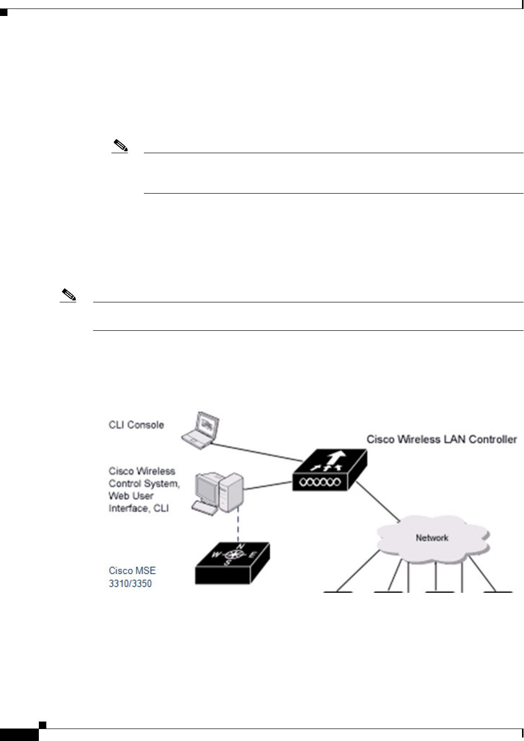
Figure 1-1 shows the Cisco wireless LAN controller components, which can be simultaneously deployed
across multiple floors and buildings.
Figure 1-1 Cisco UWN Solution Components
Single-Controller Deployments
A standalone controller can support lightweight access points across multiple floors and buildings
simultaneously and support the following features:
• Autodetecting and autoconfiguring lightweight access points as they are added to the network.
1-3
Cisco Wireless LAN Controller Configuration Guide
OL-21524-02
Chapter 1 Overview
Cisco Unified Wireless Network Solution Overview
• Full control of lightweight access points.
• Lightweight access points connect to controllers through the network. The network equipment may
or may not provide Power over Ethernet (PoE) to the access points.
Some controllers use redundant Gigabit Ethernet connections to bypass single network failures.
Note Some controllers can connect through multiple physical ports to multiple subnets in the network. This
feature can be helpful when you want to confine multiple VLANs to separate subnets.
Figure 1-2 shows a typical single-controller deployment.
Figure 1-2 Single-Controller Deployment
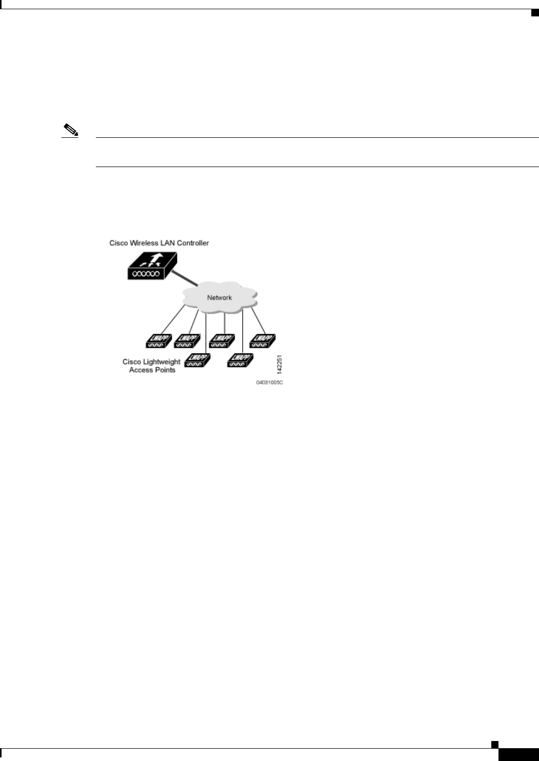
Multiple-Controller Deployments
Each controller can support lightweight access points across multiple floors and buildings
simultaneously. However, full functionality of the Cisco wireless LAN solution occurs when it includes
multiple controllers. A multiple-controller system has the following additional features:
• Autodetecting and autoconfiguring RF parameters as the controllers are added to the network.
• Same-subnet (Layer 2) roaming and inter-subnet (Layer 3) roaming.
• Automatic access point failover to any redundant controller with a reduced access point load (see
the Cisco Wireless LAN Controller Failover Protection, page 1-15).
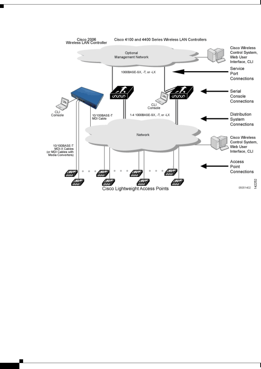
Figure 1-3 shows a typical multiple-controller deployment. The figure also shows an optional dedicated
management network and the three physical connection types between the network and the controllers.
1-4
Cisco Wireless LAN Controller Configuration Guide
OL-21524-02
Chapter 1 Overview
Operating System Software
Figure 1-3 Typical Multiple-Controller Deployment
Operating System Software
The operating system software controls controllers and lightweight access points. It includes full
operating system security and radio resource management (RRM) features.
Operating System Security
Operating system security bundles Layer 1, Layer 2, and Layer 3 security components into a simple,
Cisco WLAN solution-wide policy manager that creates independent security policies for each of up to
16 wireless LANs. See “Cisco UWN Solution WLANs” section on page 1-14.
The 802.11 Static WEP weaknesses can be overcome using the following robust industry-standard
security solutions:
• 802.1X dynamic keys with extensible authentication protocol (EAP).
• Wi-Fi protected access (WPA) dynamic keys. The Cisco WLAN solution WPA implementation
includes:
–
Temporal key integrity protocol (TKIP) and message integrity code checksum dynamic keys
–
WEP keys, with or without a preshared key passphrase
• RSN with or without a preshared key

1-5
Cisco Wireless LAN Controller Configuration Guide
OL-21524-02
Chapter 1 Overview
Layer 2 and Layer 3 Operation
• Optional MAC filtering
The WEP problem can be further solved using the following industry-standard Layer 3 security
solutions:
• Passthrough VPNs
• Local and RADIUS MAC address filtering
• Local and RADIUS user/password authentication
• Manual and automated disabling to block access to network services. In manual disabling, you block
access using client MAC addresses. In automated disabling, which is always active, the operating
system software automatically blocks access to network services for a user-defined period of time
when a client fails to authenticate for a fixed number of consecutive attempts. This feature can be
used to deter brute-force login attacks.
These and other security features use industry-standard authorization and authentication methods to
ensure the highest possible security for your business-critical wireless LAN traffic.
Cisco WLAN Solution Wired Security
Each controller and lightweight access point is manufactured with a unique, signed X.509 certificate.
These signed certificates are used to verify downloaded code before it is loaded, ensuring that hackers
do not download malicious code into any controller or lightweight access point.
The controllers and lightweight access points also use the signed certificates to verify the downloaded
code before it is loaded, ensuring that hackers do not download malicious code into any Cisco wireless
controller or lightweight access point.
Layer 2 and Layer 3 Operation
Lightweight Access Point Protocol (LWAPP) communications between the controller and lightweight
access points can be conducted at Layer 2 or Layer 3. Control and Provisioning of Wireless Access
Points protocol (CAPWAP) communications between the controller and lightweight access points are
conducted at Layer 3. Layer 2 mode does not support CAPWAP.
Note Controller software release 5.2 or later releases support only Layer 3 CAPWAP mode, controller
software releases 5.0 and 5.1 support only Layer 3 LWAPP mode, and controller software releases prior
to 5.0 support Layer 2 or Layer 3 LWAPP mode.
Note The IPv4 network layer protocol is supported for transport through a CAPWAP or LWAPP controller
system. IPv6 (for clients only) and Appletalk are also supported but only on Cisco 5500 Series
Controllers, Cisco 4400 Series Controllers, and the Cisco WiSM. Other Layer 3 protocols (such as IPX,
DECnet Phase IV, OSI CLNP, and so on) and Layer 2 (bridged) protocols (such as LAT and NetBeui)
are not supported.

1-6
Cisco Wireless LAN Controller Configuration Guide
OL-21524-02
Chapter 1 Overview
Cisco Wireless LAN Controllers
Operational Requirements
The requirement for Layer 3 LWAPP communications is that the controller and lightweight access points
can be connected through Layer 2 devices on the same subnet or connected through Layer 3 devices
across subnets. Another requirement is that the IP addresses of access points should be either statically
assigned or dynamically assigned through an external DHCP server.
The requirement for Layer 3 CAPWAP communications across subnets is that the controller and
lightweight access points are connected through Layer 3 devices. Another requirement is that the IP
addresses of access points should be either statically assigned or dynamically assigned through an
external DHCP server.
Configuration Requirements
When you are operating the Cisco wireless LAN solution in Layer 2 mode, you must configure a
management interface to control your Layer 2 communications.
When you are operating the Cisco wireless LAN solution in Layer 3 mode, you must configure an
AP-manager interface to control lightweight access points and a management interface as configured for
Layer 2 mode.
Cisco Wireless LAN Controllers
When you are adding lightweight access points to a multiple-controller deployment network, it is
convenient to have all lightweight access points associate with one master controller on the same subnet.
That way, the you do not have to log into multiple controllers to find out which controller newly-added
lightweight access points associated with.
One controller in each subnet can be assigned as the master controller while adding lightweight access
points. As long as a master controller is active on the same subnet, all new access points without a
primary, secondary, and tertiary controller assigned automatically attempt to associate with the master
controller. This process is described in the “Cisco Wireless LAN Controller Failover Protection” section
on page 1-15.
You can monitor the master controller using the WCS Web User Interface and watch as access points
associate with the master controller. You can then verify the access point configuration and assign a
primary, secondary, and tertiary controller to the access point, and reboot the access point so it
reassociates with its primary, secondary, or tertiary controller.
Note Lightweight access points without a primary, secondary, and tertiary controller assigned always search
for a master controller first upon reboot. After adding lightweight access points through the master
controller, you should assign primary, secondary, and tertiary controllers to each access point. We
recommend that you disable the master setting on all controllers after initial configuration.

1-7
Cisco Wireless LAN Controller Configuration Guide
OL-21524-02
Chapter 1 Overview
Controller Platforms
Client Location
When you use Cisco WCS in your Cisco wireless LAN solution, controllers periodically determine the
client, rogue access point, rogue access point client, radio frequency ID (RFID) tag location and store
the locations in the Cisco WCS database. For more information on location solutions, see these
documents:
Cisco Wireless Control System Configuration Guide:
http://www.cisco.com/en/US/products/ps6305/products_installation_and_configuration_guides_list.ht
ml
Cisco Location Appliance Configuration Guide:
http://www.cisco.com/en/US/products/ps6386/products_installation_and_configuration_guides_list.ht
ml
Cisco 3300 Series Mobility Services Engine Configuration Guide:
http://www.cisco.com/en/US/products/ps9742/products_installation_and_configuration_guides_list.ht
ml
Controller Platforms
Controllers are enterprise-class high-performance wireless switching platforms that support 802.11a/n
and 802.11b/g/n protocols. They operate under control of the operating system, which includes the radio
resource management (RRM), creating a Cisco UWN solution that can automatically adjust to real-time
changes in the 802.11 RF environment. Controllers are built around high-performance network and
security hardware, resulting in highly reliable 802.11 enterprise networks with unparalleled security.
The following controllers are supported for use with software release 7.0.116.0:
• Cisco 2100 Series Controller
• Cisco 2500 Series Controller
• Cisco 4400 Series Controller
• Cisco 5500 Series Controller
• Catalyst 6500 series switch Wireless Services Module (WiSM2s)
• Cisco 7600 Series Router Wireless Services Module (WiSM)
• Cisco 28/37/38xx Series Integrated Services Router with Controller Network Module
• Catalyst 3750G Integrated Wireless LAN Controller Switch
• Cisco Flex 7500 Series Controller
Cisco 2100 Series Controller
The Cisco 2100 Series Wireless LAN Controllers work with Cisco lightweight access points and the
Cisco Wireless Control System (WCS) to provide system-wide wireless LAN functions. Each controller
controls up to 6, 12, or 25 lightweight access points for multiple-controller architectures that are typical
of enterprise branch deployments. It may also be used for single controller deployments for small and
medium-sized environments.

1-8
Cisco Wireless LAN Controller Configuration Guide
OL-21524-02
Chapter 1 Overview
Controller Platforms
Caution Do not connect a Power-over-Ethernet (PoE) cable to the controller’s console port. Doing so may
damage the controller.
Note Wait at least 20 seconds before reconnecting an access point to the controller. Otherwise, the controller
may fail to detect the device.
Features Not Supported
This hardware feature is not supported on Cisco 2100 Series Controllers:
• Service port (separate out-of-band management 10/100-Mbps Ethernet interface)
• Cisco 2100 Series Controller does not support the access point AP802.
These software features are not supported on Cisco 2100 Series Controllers:
• VPN termination (such as IPsec and L2TP)
• VPN passthrough option
Note You can replicate this functionality on a Cisco 2100 Series Controller by creating an open
WLAN using an ACL.
• Termination of guest controller tunnels (origination of guest controller tunnels is supported)
• External web authentication web server list
• Spanning Tree Protocol (STP)
• Port mirroring
• AppleTalk
• QoS per-user bandwidth contracts
• IPv6 pass-through
• Link aggregation (LAG)
• Multicast-unicast mode
Cisco 2500 Series Controller
The Cisco 2500 Series Wireless Controller works in conjunction with Cisco lightweight access points
and the Cisco Wireless Control System (WCS) to provide system-wide wireless LAN functions. As a
component of the Cisco Unified Wireless Network (CUWN), the Cisco 2500 Series controller provides
real-time communication between a wireless access points and other devices to deliver centralized
security policies, guest access, wireless intrusion prevention system (wIPS), context-aware (location),
RF management, quality of services for mobility services such as voice and video, and OEAP support
for the teleworker solution.
Cisco 2500 Series Wireless Controllers support up to 50 lightweight access points in increments of 5 and
25 access points with a minimum of 5 access points. The Cisco 2504 Wireless Controller comes with
four 4 Giga bit Ethernet ports, two of which can provide power directly to Cisco lightweight access
points.

1-9
Cisco Wireless LAN Controller Configuration Guide
OL-21524-02
Chapter 1 Overview
Controller Platforms
The Cisco 2500 Series Controller offers robust coverage with 802.11 a/b/g or delivers reliability using
802.11n and Cisco Next-Generation Wireless Solutions and Cisco Enterprise Wireless Mesh.
The Cisco 2500 Series Controller has the following limitations:
• Does not support wired guest access
• Cannot be configured as an auto anchor controller. However you can configure it as a foreign
controller
• Supports only multicast-multicast mode
• Does not support bandwidth contract feature
• Does not support access points in direct connect mode
• Does not support service port
• Apple Talk Bridging
• LAG
• Wired Guest
Cisco 4400 Series Controllers
The Cisco 4400 Series Wireless LAN Controller is available in two models: 4402 and 4404. The 4402
supports up to 50 lightweight access points while the 4404 supports up to 100, making it ideal for large
enterprises and high-density applications.
The Cisco 4400 Series Controller can be equipped with one or two power supplies. When the controller
is equipped with two power supplies, the power supplies are redundant, and either power supply can
continue to power the controller if the other power supply fails.
Cisco 5500 Series Controllers
The Cisco 5500 Series Wireless LAN Controller is currently available in one model: 5508. The 5508
controller supports up to 500 lightweight access points and 7000 wireless clients (or 5000 wireless
clients and 2500 RFID tags when using the client location feature), making it ideal for large enterprises
and high-density applications.
The Cisco 5500 Series Controller can be equipped with one or two power supplies. When the controller
is equipped with two power supplies, the power supplies are redundant, and either power supply can
continue to power the controller if the other power supply fails.
Features Not Supported
These software features are not supported on Cisco 5500 Series Controllers:
• Static AP-manager interface
Note For Cisco 5500 Series Controllers, you are not required to configure an AP-manager
interface. The management interface acts like an AP-manager interface by default, and the
access points can join on this interface.
• Asymmetric mobility tunneling

1-10
Cisco Wireless LAN Controller Configuration Guide
OL-21524-02
Chapter 1 Overview
Controller Platforms
• Spanning Tree Protocol (STP)
• Port mirroring
• Layer 2 access control list (ACL) support
• VPN termination (such as IPsec and L2TP)
• VPN passthrough option
Note You can replicate this functionality on a Cisco 5500 Series Controller by creating an open
WLAN using an ACL.
• Configuration of 802.3 bridging, AppleTalk, and Point-to-Point Protocol over Ethernet (PPPoE)
Note The Cisco 5500 Series Controllers bridge these packets by default. If desired, you can use
ACLs to block the bridging of these protocols.
Cisco Flex 7500 Series Controller
The Cisco Flex 7500 Series Controller enables you to deploy full featured, scalable, and secure hybrid
REAP network services across geographic locations. Cisco Flex 7500 Series Controller virtualizes the
complex security, management, configuration and troubleshooting operations within the data center and
then transparently extends those services to each store. Deployments using Cisco Flex 7500 Series
Controller are easier for IT to set up, manage and scale.
The Cisco Flex 7500 Series Controller is designed to meet the scaling requirements to deploy the hybrid
REAP solution in branch networks. Cisco Unified Wireless Solution supports two major deployment
models: hybrid REAP and monitor mode. Hybrid REAP is designed to support wireless branch networks
by allowing the data to be switched locally while the access points are being controlled and managed by
a centralized controller. It aims at delivering a cost effective hybrid REAP solution on a large scale.
Cisco Flex 7500 Series Controller supports the following access points: 1140, 3500, 1250, 1260, 1040,
1130, 1240, and ISR 891.
The Cisco Flex 7500 Series Controller provides the following features:
• Increases scalability with 2000 AP support.
• Increased resiliency using controller redundancy and hybrid REAP Fault Tolerance.
• Increased traffic segmentation using hybrid-REAP (central and local switching).
• Increased security (PCI compliance) by supporting Enhanced wIPS for hybrid REAP (ELM).
• Replicates store designs using AP groups and hybrid REAP groups.
Catalyst 6500 Series Switch Wireless Services Module
The Catalyst 6500 series switch Wireless Services Module (WiSM) is an integrated Catalyst 6500 series
switch and two Cisco 4404 controllers that supports up to 300 lightweight access points. The switch has
eight internal Gigabit Ethernet ports that connect the switch and the controller. The switch and the
internal controller run separate software versions, which must be upgraded separately.

1-11
Cisco Wireless LAN Controller Configuration Guide
OL-21524-02
Chapter 1 Overview
Controller Platforms
Note Without any other service module installed, the Catalyst 6509 switch chassis can support up to seven
Cisco WiSMs, and the Catalyst 6506 with a Supervisor 720 can support up to four Cisco WiSMs. If one
or more service modules are installed, the chassis can support up to a maximum of four service modules
(WiSMs included). Redundant supervisors cannot be used with these maximum configurations.
Note The Cisco WiSM controllers do not support port mirroring.
Note The Cisco WiSM module has two controllers and if you use the hw-module module command to reboot
the module from the Catalyst 6K console, both controllers are rebooted. Alternatively, WISM controllers
can be rebooted by creating a session to the controller and resetting it. It is only when you boot the WiSM
module from the Catalyst 6K console, that both the controllers are rebooted.
See the following documents for additional information:
• Catalyst 6500 Series Switch Installation Guide
• Catalyst 6500 Series Switch Wireless Services Module Installation and Configuration Note
• Release Notes for Catalyst 6500 Series Switch Wireless LAN Services Module
• Configuring a Cisco Wireless Services Module and Wireless Control System
• Catalyst 6500 Series Switch and Cisco 7600 Series Router Wireless Services Module Installation
and Verification Note
You can find these documents at these URLs:
http://www.cisco.com/en/US/products/hw/switches/ps708/tsd_products_support_series_home.html
http://www.cisco.com/en/US/docs/wireless/technology/wism/technical/reference/appnote.html
http://www.cisco.com/en/US/docs/wireless/technology/wism/installation/note/78_17121.html
Cisco 7600 Series Router Wireless Services Module
The Cisco 7600 series Router Wireless Services Module (WiSM) is an integrated Cisco 7600 series
router and two Cisco 4404 Controllers that supports up to 300 lightweight access points. The router has
eight internal Gigabit Ethernet ports that connect the router and the controller. The router and the internal
controller run separate software versions, which must be upgraded separately.
Note The WiSM is supported on Cisco 7600 series routers running only Cisco IOS Release 12.2(18)SXF5 or
later.
Note The Cisco WiSM controllers do not support port mirroring.

1-12
Cisco Wireless LAN Controller Configuration Guide
OL-21524-02
Chapter 1 Overview
Controller Platforms
Note The Cisco WiSM module has two controllers and if you use the hw-module module command to reboot
the module from the Catalyst 6K console, both controllers are rebooted. Alternatively, WISM controllers
can be rebooted by creating a session to the controller and resetting it. It is only when you boot the WiSM
module from the Catalyst 6K console, that both the controllers are rebooted.
See the following documents for additional information:
• Cisco 7600 Series Router Installation Guide
• Cisco 7600 Series Router Software Configuration Guide
• Cisco 7600 Series Router Command Reference
• Configuring a Cisco Wireless Services Module and Wireless Control System
• Catalyst 6500 Series Switch and Cisco 7600 Series Router Wireless Services Module Installation
and Verification Note
You can find these documents at these URLs:
http://www.cisco.com/en/US/products/hw/routers/ps368/tsd_products_support_series_home.html
http://www.cisco.com/en/US/docs/wireless/technology/wism/technical/reference/appnote.html
http://www.cisco.com/en/US/docs/wireless/technology/wism/installation/note/78_17121.html
Cisco 28/37/38xx Series Integrated Services Router
The Cisco 28/37/38xx Series Integrated Services Router is an integrated 28/37/38xx router and Cisco
controller network module that support up to 6, 8, 12, or 25 lightweight access points, depending on the
version of the network module. The versions that support 8, 12, or 25 access points and the
NME-AIR-WLC6-K9 6-access-point version feature a high-speed processor and more onboard memory
than the NM-AIR-WLC6-K9 6-access-point version. An internal Fast Ethernet port (on the
NM-AIR-WLC6-K9 6-access-point version) or an internal Gigabit Ethernet port (on the 8-, 12-, and
25-access-point versions and on the NME-AIR-WLC6-K9 6-access-point version) connects the router
and the integrated controller. The router and the internal controller run separate software versions, which
must be upgraded separately. See the following documents for additional information:
• Cisco Wireless LAN Controller Network Module Feature Guide
• Cisco 28/37/38xx Series Hardware Installation Guide
You can find these documents at this URL:
http://www.cisco.com/en/US/products/hw/wireless/index.html
Note The controller network module does not support port mirroring.
Note The Cisco 2801 Integrated Services Router does not support the controller network module.

1-13
Cisco Wireless LAN Controller Configuration Guide
OL-21524-02
Chapter 1 Overview
Cisco UWN Solution Wired Connections
Catalyst 3750G Integrated Wireless LAN Controller Switch
The Catalyst 3750G Integrated Wireless LAN Controller Switch is an integrated Catalyst 3750 switch
and Cisco 4400 Series Controller that support up to 25 or 50 lightweight access points. The switch has
two internal Gigabit Ethernet ports that connect the switch and the controller. The switch and the internal
controller run separate software versions, which must be upgraded separately.
Note The controller in the Catalyst 3750G Integrated Wireless LAN Controller Switch does not support the
Spanning Tree Protocol (STP).
See the following documents for additional information:
• Catalyst 3750G Integrated Wireless LAN Controller Switch Getting Started Guide
• Catalyst 3750 Switch Hardware Installation Guide
• Release Notes for the Catalyst 3750 Integrated Wireless LAN Controller Switch, Cisco IOS Release
12.2(25)FZ
You can find these documents at this URL:
http://www.cisco.com/en/US/products/hw/switches/ps5023/tsd_products_support_series_home.html
Cisco UWN Solution Wired Connections
The Cisco UWN solution components communicate with each other using industry-standard Ethernet
cables and connectors. Details of the wired connections are as follows:
• The Cisco 2100 Series Controller connects to the network using from one to six 10/100BASE-T
Ethernet cables.
• The Cisco 4402 Controller connects to the network using one or two fiber-optic Gigabit Ethernet
cables, and the Cisco 4404 Controller connects to the network using up to four fiber-optic Gigabit
Ethernet cables.
• The Cisco 5508 Controller connects to the network using up to eight fiber-optic Gigabit Ethernet
cables.
• The controllers in the Wireless Services Module (WiSM), installed in a Catalyst 6500 series switch
or a Cisco 7600 series router, connect to the network through ports on the switch or router.
• The Wireless LAN Controller Network Module, installed in a Cisco Integrated Services Router,
connects to the network through the ports on the router.
• The controller in the Catalyst 3750G Integrated Wireless LAN Controller Switch connects to the
network through the ports on the switch.
• Cisco lightweight access points connect to the network using 10/100BASE-T Ethernet cables. The
standard CAT-5 cable can also be used to conduct power for the lightweight access points from a
network device equipped with Power over Ethernet (PoE) capability. This power distribution plan
can be used to reduce the cost of individual AP power supplies and related cabling.

1-14
Cisco Wireless LAN Controller Configuration Guide
OL-21524-02
Chapter 1 Overview
Cisco UWN Solution WLANs
Cisco UWN Solution WLANs
The Cisco UWN solution can control up to 512 WLANs for lightweight access points. Each WLAN has
a separate WLAN ID (1 through 512), a separate profile name, and a WLAN SSID and can be assigned
with unique security policies. The lightweight access points broadcast all active Cisco UWN solution
WLAN SSIDs and enforce the policies defined for each WLAN.
Note Cisco 2106, 2112, and 2125 Controllers support only up to 16 WLANs.
Note We recommend that you assign one set of VLANs for WLANs and a different set of VLANs for
management interfaces to ensure that controllers operate with optimum performance and ease of
management.
If management over wireless is enabled across the Cisco UWN solution, you can manage the system
across the enabled WLAN using CLI and Telnet, http/https, and SNMP.
To configure WLANs, see Chapter 7, “Configuring WLANs.”
File Transfers
You can upload and download operating system code, configuration, and certificate files to and from the
controller using the GUI, CLI, or Cisco WCS as follows:
• To use the controller GUI or CLI, see Chapter 10, “Managing Controller Software and
Configurations.”
• To use Cisco WCS to upgrade software, see the Cisco Wireless Control System Configuration Guide
at:
http://www.cisco.com/en/US/products/ps6305/products_installation_and_configuration_guides_lis
t.html
Power Over Ethernet
Lightweight access points can receive power through their Ethernet cables from 802.3af-compatible
Power over Ethernet (PoE) devices, which can reduce the cost of discrete power supplies, additional
wiring, conduits, outlets, and installation time. PoE frees you from having to mount lightweight access
points or other powered equipment near AC outlets, which provides greater flexibility in positioning the
access points for maximum coverage.
When you are using PoE, you run a single CAT-5 cable from each lightweight access point to
PoE-equipped network elements, such as a PoE power hub or a Cisco WLAN Solution single-line PoE
injector. When the PoE equipment determines that the lightweight access point is PoE-enabled, it sends
48 VDC over the unused pairs in the Ethernet cable to power the access point.
The PoE cable length is limited by the 100BASE-T or 10BASE-T specification to 100 m or 200 m,
respectively.
Lightweight access points can receive power from an 802.3af-compliant device or from the external
power supply.

1-15
Cisco Wireless LAN Controller Configuration Guide
OL-21524-02
Chapter 1 Overview
Cisco Wireless LAN Controller Memory
Cisco Wireless LAN Controller Memory
The controller contains two kinds of memory: volatile RAM, which holds the current, active controller
configuration, and NVRAM (nonvolatile RAM), which holds the reboot configuration. When you are
configuring the operating system in controller, you are modifying volatile RAM; you must save the
configuration from the volatile RAM to the NVRAM to ensure that the controller reboots in the current
configuration.
Knowing which memory you are modifying is important when you are doing the following tasks:
• Using the configuration wizard
• Clearing the controller configuration
• Saving configurations
• Resetting the controller
• Logging out of the CLI
Cisco Wireless LAN Controller Failover Protection
During installation, we recommend that you connect all lightweight access points to a dedicated
controller, and configure each lightweight access point for final operation. This step configures each
lightweight access point for a primary, secondary, and tertiary controller and allows it to store the
configured mobility group information.
During failover recovery, the following tasks are performed:
• The configured access point attempts to contact the primary, secondary, and tertiary controllers, and
then attempts to contact the IP addresses of the other controllers in the mobility group.
• DNS is resolved with controller IP address.
• DHCP servers get the controller IP Addresses (vendor specific option 43 in DHCP offer).
In multiple-controller deployments, if one controller fails, the access points perform the following tasks:
• If the lightweight access point has a primary, secondary, and tertiary controller assigned, it attempts
to associate with that controller.
• If the access point has no primary, secondary, or tertiary controllers assigned or if its primary,
secondary, or tertiary controllers are unavailable, it attempts to associate with a master controller.
• If the access point finds no master controller, it attempts to contact stored mobility group members
by the IP address.
• If the mobility group members are available, and if the lightweight access point has no primary,
secondary, and tertiary controllers assigned and there is no master controller active, it attempts to
associate with the least-loaded controller to respond to its discovery messages.
When sufficient controllers are deployed, if one controller fails, active access point client sessions are
momentarily dropped while the dropped access point associates with another controller, allowing the
client device to immediately reassociate and reauthenticate.
To know more about high availability, see
http://www.cisco.com/en/US/products/ps6366/products_tech_note09186a00809a3f5d.shtml
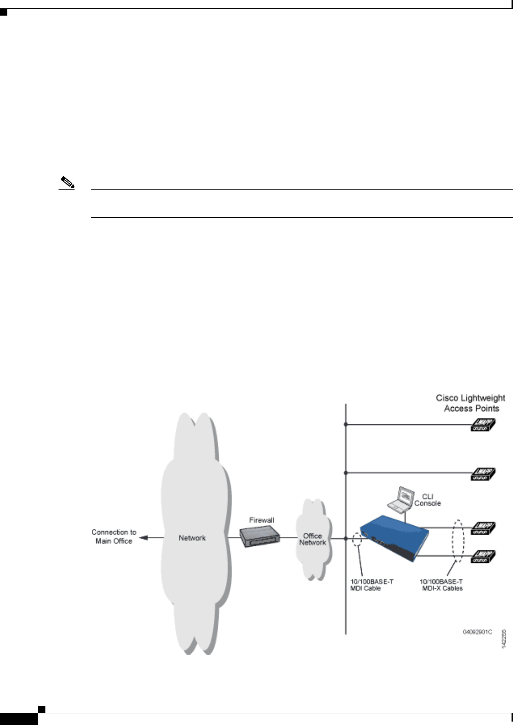
1-16
Cisco Wireless LAN Controller Configuration Guide
OL-21524-02
Chapter 1 Overview
Network Connections to Cisco Wireless LAN Controllers
Network Connections to Cisco Wireless LAN Controllers
Regardless of the operating mode, all controllers use the network as an 802.11 distribution system.
Regardless of the Ethernet port type or speed, each controller monitors and communicates with its
related controllers across the network. The following sections give details of these network connections:
• Cisco 2100 Series Wireless LAN Controllers, page 1-16
• Cisco 4400 Series Wireless LAN Controllers, page 1-17
• Cisco 5500 Series Wireless LAN Controllers, page 1-17
Note Chapter 3, “Configuring Ports and Interfaces,” provides information on how to configure the controller’s
ports and how to assign interfaces to them.
Cisco 2100 Series Wireless LAN Controllers
Cisco 2100 Series Controller can communicate with the network through any one of their physical data
ports, because the logical management interface can be assigned to one of the ports. The physical port
description is as follows:
• Up to six 10/100BASE-T cables can plug into the six back-panel data ports on the Cisco 2100 series
controller chassis. The Cisco 2100 series also has two PoE ports (ports 7 and 8).
Figure 1-4 shows connections to the Cisco 2100 Series Controller.
Figure 1-4 Physical Network Connections to the Cisco 2100 Series Controller
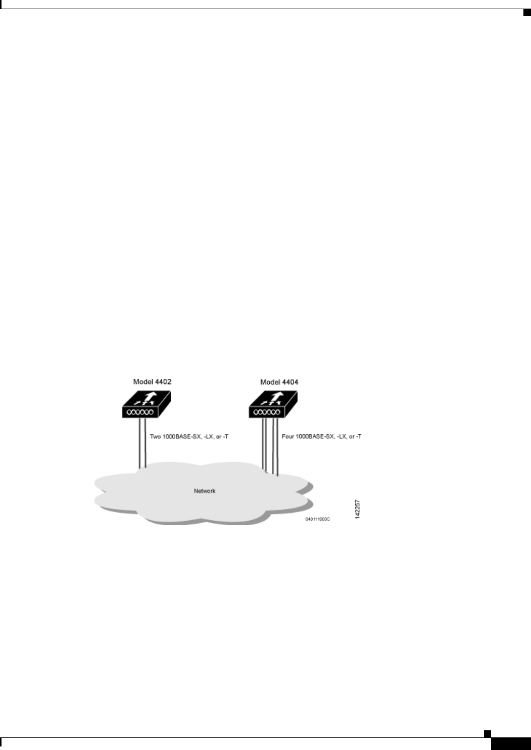
1-17
Cisco Wireless LAN Controller Configuration Guide
OL-21524-02
Chapter 1 Overview
Network Connections to Cisco Wireless LAN Controllers
Cisco 4400 Series Wireless LAN Controllers
Cisco 4400 Series Controllers can communicate with the network through one or two pairs of physical
data ports, and the logical management interface can be assigned to the ports.
• For the Cisco 4402 Controller, up to two of the following connections are supported in any
combination:
–
1000BASE-T (Gigabit Ethernet, front panel, RJ-45 physical port, UTP cable).
–
1000BASE-SX (Gigabit Ethernet, front panel, LC physical port, multimode 850nM (SX)
fiber-optic links using LC physical connectors).
–
1000BASE-LX (Gigabit Ethernet, front panel, LC physical port, multimode 1300nM (LX/LH)
fiber-optic links using LC physical connectors).
• For the Cisco 4404 Controller, up to four of the following connections are supported in any
combination:
–
1000BASE-T (Gigabit Ethernet, front panel, RJ-45 physical port, UTP cable).
–
1000BASE-SX (Gigabit Ethernet, front panel, LC physical port, multi-mode 850nM (SX)
fiber-optic links using LC physical connectors).
–
1000BASE-LX (Gigabit Ethernet, front panel, LX physical port, multi-mode 1300nM (LX/LH)
fiber-optic links using LC physical connectors).
Figure 1-5 shows connections to the Cisco 4400 Series Controller.
Figure 1-5 Physical Network Connections to Cisco 4402 and 4404 Controllers
Cisco 5500 Series Wireless LAN Controllers
Cisco 5500 Series Controllers can communicate with the network through up to eight physical data ports,
and the logical management interface can be assigned to the ports.
For the Cisco 5508 Controller, up to eight of the following connections are supported in any
combination:
• 1000BASE-T (Gigabit Ethernet, front panel, RJ-45 physical port, UTP cable).

1-18
Cisco Wireless LAN Controller Configuration Guide
OL-21524-02
Chapter 1 Overview
Network Connections to Cisco Wireless LAN Controllers
• 1000BASE-SX (Gigabit Ethernet, front panel, LC physical port, multi-mode 850nM (SX)
fiber-optic links using LC physical connectors).
• 1000BASE-LX (Gigabit Ethernet, front panel, LX physical port, multi-mode 1300nM (LX/LH)
fiber-optic links using LC physical connectors).

CHAPTER
2-1
Cisco Wireless LAN Controller Configuration Guide
OL-21524-02
2
Using the Web-Browser and CLI Interfaces
This chapter describes how to initially configure and log into the controller. It contains these sections:
• Using the Configuration Wizard, page 2-1
• Using the GUI, page 2-16
• Using the CLI, page 2-22
• Using the AutoInstall Feature for Controllers Without a Configuration, page 2-26
• Managing the System Date and Time, page 2-29
• Configuring Telnet and SSH Sessions, page 2-34
• Enabling Wireless Connections to the GUI and CLI, page 2-37
Using the Configuration Wizard
Note Before you configure your controller for basic operation, see quick start guide or installation guide for
your controller to complete any necessary hardware procedures.
The configuration wizard enables you to configure basic settings on the controller. You can run the
wizard after you receive the controller from the factory or after the controller has been reset to factory
defaults. The configuration wizard is available in GUI or CLI format.
Note To configure the controller in the Catalyst 3750G Integrated Wireless LAN Controller Switch, we
recommend that you use the GUI configuration wizard that launches from the 3750 Device Manager. See
the Catalyst 3750G Integrated Wireless LAN Controller Switch Getting Started Guide for instructions.
Note See the “Resetting the Controller to Default Settings” section on page 4-124 for instructions on returning
the controller to factory defaults.
Connecting the Controller’s Console Port
Before you can configure the controller for basic operations, you need to connect it to a PC that uses a
VT-100 terminal emulation program (such as HyperTerminal, ProComm, Minicom, or Tip).

2-2
Cisco Wireless LAN Controller Configuration Guide
OL-21524-02
Chapter 2 Using the Web-Browser and CLI Interfaces
Using the Configuration Wizard
To connect to the controller’s console port, follow these steps:
Step 1 Connect one end of a null-modem serial cable to the controller’s console port and the other end to your
PC’s serial port.
Note On Cisco 5500 Series Controllers, you can use either the RJ-45 console port or the USB console
port. If you use the USB console port, plug the 5-pin mini Type B connector into the controller’s
USB console port and the other end of the cable into the PC’s USB Type A port. The first time
that you connect a Windows PC to the USB console port, you are prompted to install the USB
console driver. Follow the installation prompts to install the driver. The USB console driver maps
to a COM port on your PC; you then need to map the terminal emulator application to the COM
port.
Step 2 Start the PC’s VT-100 terminal emulation program.
Step 3 Configure the terminal emulation program for these parameters:
• 9600 baud
• 8 data bits
• 1 stop bit
• No parity
• No hardware flow control
Step 4 Plug the AC power cord into the controller and a grounded 100 to 240 VAC, 50/60-Hz electrical outlet.
Step 5 Turn on the power supply. The bootup script displays operating system software initialization (code
download and power-on self test verification) and basic configuration.
If the controller passes the power-on self test, the bootup script runs the configuration wizard, which
prompts you for basic configuration input.
Using the GUI Configuration Wizard
To configure the controller using the controller GUI configuration wizard, follow these steps:
Step 1 Connect your PC to the service port and configure it to use the same subnet as the controller (for
example, 192.168.10.1).
Step 2 Start Internet Explorer 6.0 SP1 (or later) or Firefox 2.0.0.11 (or later) on your PC and browse to
http://192.168.1.1. The configuration wizard appears (see Figure 2-1).

2-3
Cisco Wireless LAN Controller Configuration Guide
OL-21524-02
Chapter 2 Using the Web-Browser and CLI Interfaces
Using the Configuration Wizard
Figure 2-1 Configuration Wizard — System Information Screen
Step 3 In the System Name text box, enter the name that you want to assign to this controller. You can enter up
to 31 ASCII characters.
Step 4 In the User Name text box, enter the administrative username to be assigned to this controller. You can
enter up to 24 ASCII characters. The default username is admin.
Step 5 In the Password and Confirm Password text boxes, enter the administrative password to be assigned to
this controller. You can enter up to 24 ASCII characters. The default password is admin.
Starting in release 7.0.116.0, the following password policy has been implemented:
• The password must contain characters from at least three of the following classes:
–
Lowercase letters
–
Uppercase letters
–
Digits
–
Special characters.
• No character in the password must be repeated more than three times consecutively.
• The new password must not be the same as the associated username and not be the username
reversed.
• The password must not be cisco, ocsic, or any variant obtained by changing the capitalization of
letters of the word Cisco. In addition, you cannot substitute 1, I, or ! for i, 0 for o, or $ for s..
Step 6 Click Next. The SNMP Summary screen appears (see Figure 2-2).

2-4
Cisco Wireless LAN Controller Configuration Guide
OL-21524-02
Chapter 2 Using the Web-Browser and CLI Interfaces
Using the Configuration Wizard
Figure 2-2 Configuration Wizard — SNMP Summary Screen
Step 7 If you want to enable Simple Network Management Protocol (SNMP) v1 mode for this controller,
choose Enable from the SNMP v1 Mode drop-down list. Otherwise, leave this parameter set to Disable.
Note SNMP manages nodes (servers, workstations, routers, switches, and so on) on an IP network.
Currently, there are three versions of SNMP: SNMPv1, SNMPv2c, and SNMPv3.
Step 8 If you want to enable SNMPv2c mode for this controller, leave this parameter set to Enable. Otherwise,
choose Disable from the SNVP v2c Mode drop-down list.
Step 9 If you want to enable SNMPv3 mode for this controller, leave this parameter set to Enable. Otherwise,
choose Disable from the SNVP v3 Mode drop-down list.
Step 10 Click Next.
Step 11 When the following message appears, click OK:
Default values are present for v1/v2c community strings. Please make sure to create new
v1/v2c community strings once the system comes up. Please make sure to create new v3 users
once the system comes up.
Note See the“Changing the Default Values of SNMP Community Strings” section on page 4-43 and
the “Changing the Default Values for SNMP v3 Users” section on page 4-45 for instructions.
The Service Interface Configuration screen appears (see Figure 2-3).
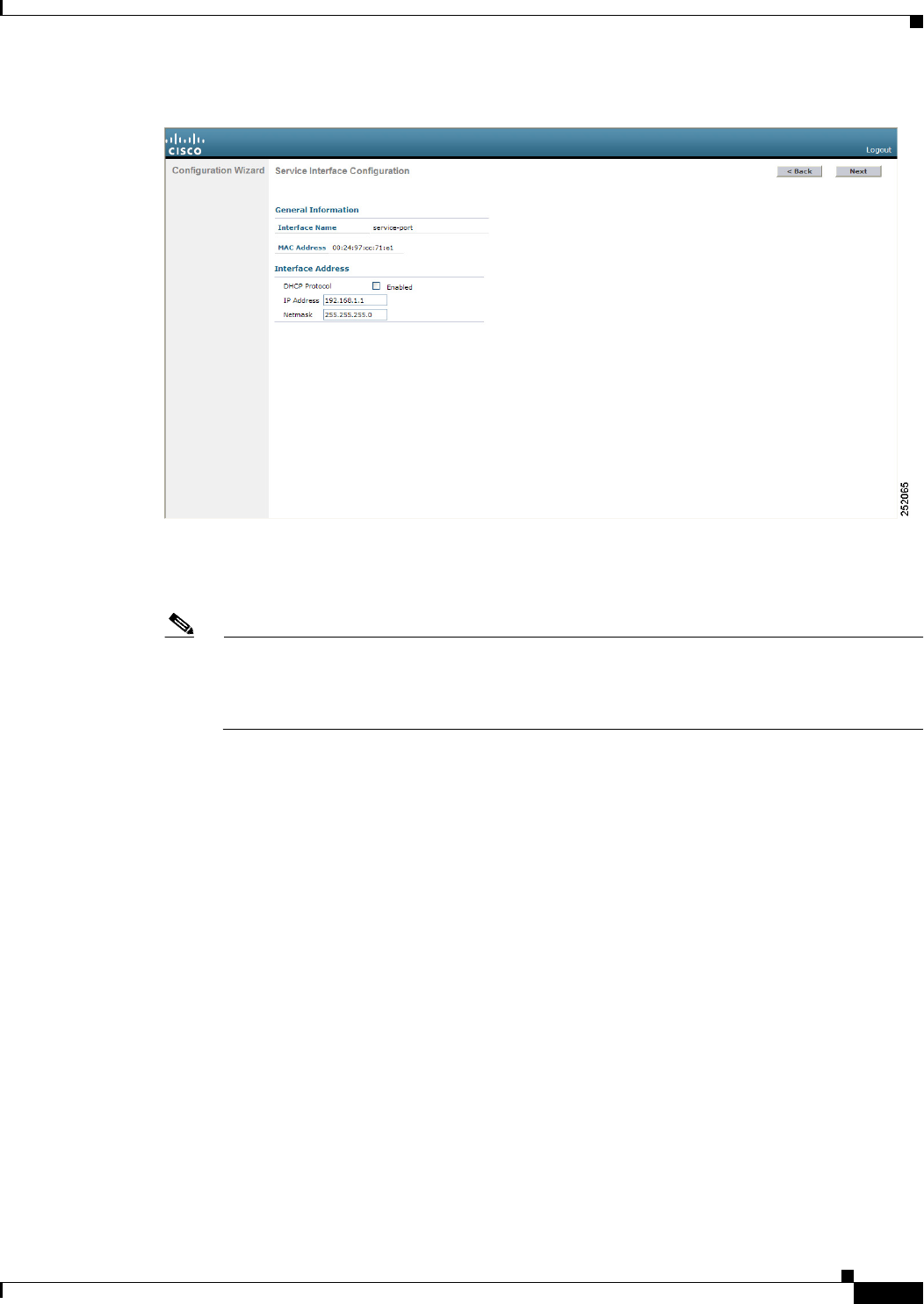
2-5
Cisco Wireless LAN Controller Configuration Guide
OL-21524-02
Chapter 2 Using the Web-Browser and CLI Interfaces
Using the Configuration Wizard
Figure 2-3 Configuration Wizard — Service Interface Configuration Screen
Step 12 If you want the controller’s service-port interface to obtain an IP address from a DHCP server, select the
DHCP Protocol Enabled check box. If you do not want to use the service port or if you want to assign
a static IP address to the service port, leave the check box unselected.
Note The service-port interface controls communications through the service port. Its IP address must
be on a different subnet from the management interface. This configuration enables you to
manage the controller directly or through a dedicated management network to ensure service
access during network downtime.
Step 13 Perform one of the following:
• If you enabled DHCP in Step 12, clear out any entries in the IP Address and Netmask text boxes,
leaving them blank.
• If you disabled DHCP in Step 12, enter the static IP address and netmask for the service port in the
IP Address and Netmask text boxes.
Step 14 Click Next. The LAG Configuration screen appears (see Figure 2-4).
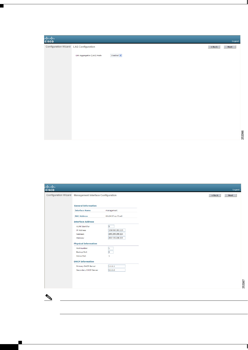
2-6
Cisco Wireless LAN Controller Configuration Guide
OL-21524-02
Chapter 2 Using the Web-Browser and CLI Interfaces
Using the Configuration Wizard
Figure 2-4 Configuration Wizard — LAG Configuration Screen
Step 15 To enable link aggregation (LAG), choose Enabled from the Link Aggregation (LAG) Mode drop-down
list. To disable LAG, leave this text box set to Disabled.
Step 16 Click Next. The Management Interface Configuration screen appears (see Figure 2-5).
Figure 2-5 Configuration Wizard — Management Interface Configuration Screen
Note The management interface is the default interface for in-band management of the controller and
connectivity to enterprise services such as AAA servers.
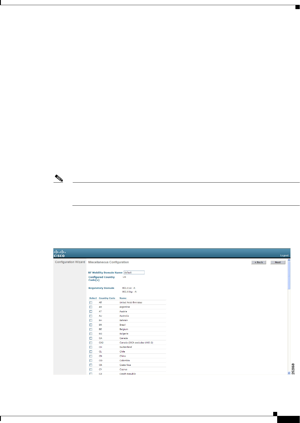
2-7
Cisco Wireless LAN Controller Configuration Guide
OL-21524-02
Chapter 2 Using the Web-Browser and CLI Interfaces
Using the Configuration Wizard
Step 17 In the VLAN Identifier text box, enter the VLAN identifier of the management interface (either a valid
VLAN identifier or 0 for an untagged VLAN). The VLAN identifier should be set to match the switch
interface configuration.
Step 18 In the IP Address text box, enter the IP address of the management interface.
Step 19 In the Netmask text box, enter the IP address of the management interface netmask.
Step 20 In the Gateway text box, enter the IP address of the default gateway.
Step 21 In the Port Number text box, enter the number of the port assigned to the management interface. Each
interface is mapped to at least one primary port.
Step 22 In the Backup Port text box, enter the number of the backup port assigned to the management interface.
If the primary port for the management interface fails, the interface automatically moves to the backup
port.
Step 23 In the Primary DHCP Server text box, enter the IP address of the default DHCP server that will supply
IP addresses to clients, the controller’s management interface, and optionally, the service port interface.
Step 24 In the Secondary DHCP Server text box, enter the IP address of an optional secondary DHCP server that
will supply IP addresses to clients, the controller’s management interface, and optionally, the service
port interface.
Step 25 Click Next. The AP-Manager Interface Configuration screen appears.
Note This screen does not appear for Cisco 5500 Series Controllers because you are not required to
configure an AP-manager interface. The management interface acts like an AP-manager
interface by default.
Step 26 In the IP Address text box, enter the IP address of the AP-manager interface.
Step 27 Click Next. The Miscellaneous Configuration screen appears (see Figure 2-6).
Figure 2-6 Configuration Wizard — Miscellaneous Configuration Screen
Step 28 In the RF Mobility Domain Name text box, enter the name of the mobility group/RF group to which you
want the controller to belong.
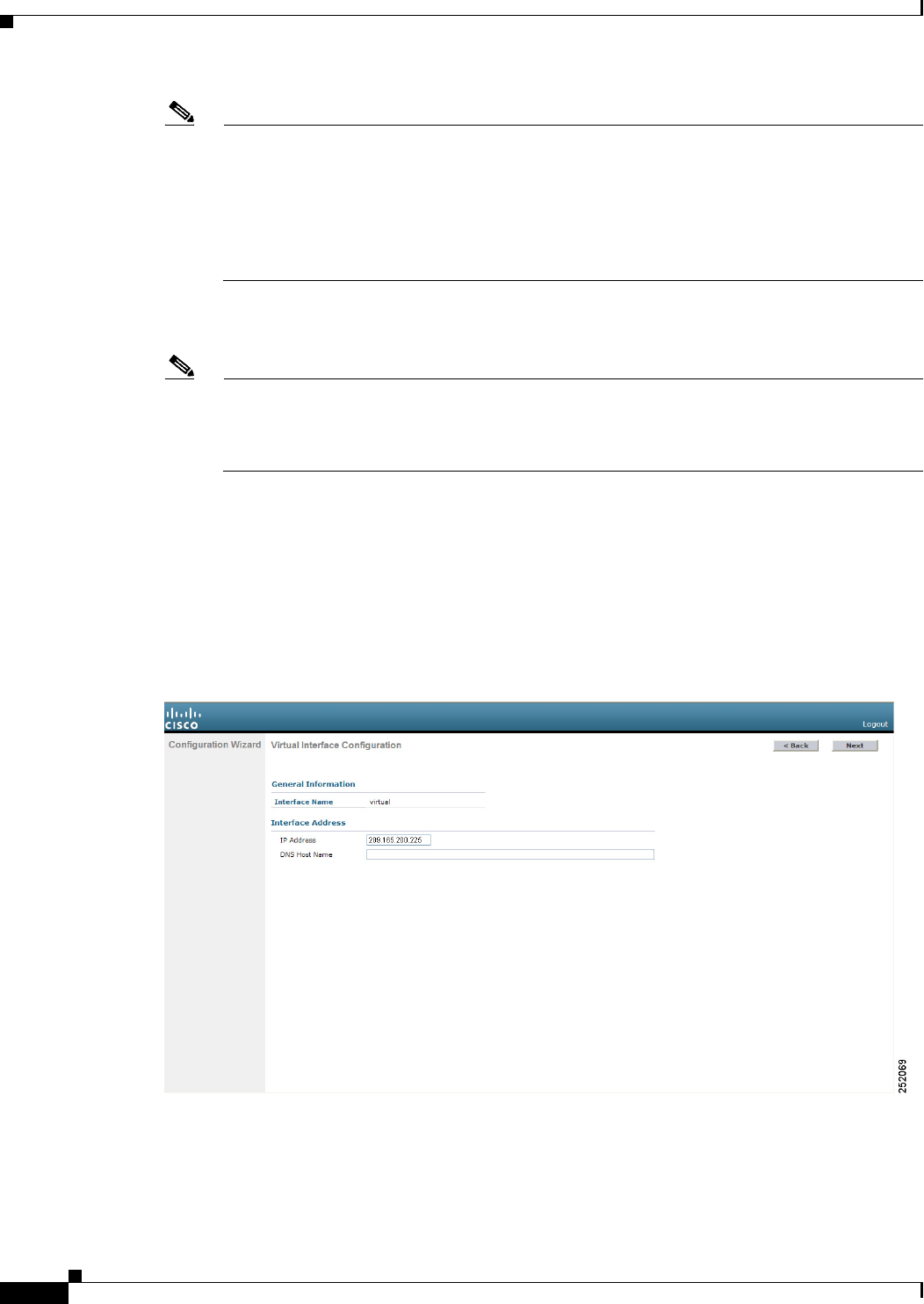
2-8
Cisco Wireless LAN Controller Configuration Guide
OL-21524-02
Chapter 2 Using the Web-Browser and CLI Interfaces
Using the Configuration Wizard
Note Although the name that you enter here is assigned to both the mobility group and the RF group,
these groups are not identical. Both groups define clusters of controllers, but they have different
purposes. All of the controllers in an RF group are usually also in the same mobility group and
vice versa. However, a mobility group facilitates scalable, system-wide mobility and controller
redundancy while an RF group facilitates scalable, system-wide dynamic RF management. See
Chapter 13, “Configuring Radio Resource Management,” and Chapter 14, “Configuring
Mobility Groups,” for more information.
Step 29 The Configured Country Code(s) text box shows the code for the country in which the controller will be
used. If you want to change the country of operation, select the check box for the desired country.
Note You can choose more than one country code if you want to manage access points in multiple
countries from a single controller. After the configuration wizard runs, you need to assign each
access point joined to the controller to a specific country. See the “Configuring Country Codes”
section on page 8-106 for instructions.
Step 30 Click Next.
Step 31 When the following message appears, click OK:
Warning! To maintain regulatory compliance functionality, the country code setting may
only be modified by a network administrator or qualified IT professional. Ensure that
proper country codes are selected before proceeding.
The Virtual Interface Configuration screen appears (see Figure 2-7).
Figure 2-7 Configuration Wizard — Virtual Interface Configuration Screen
Step 32 In the IP Address text box, enter the IP address of the controller’s virtual interface. You should enter a
fictitious, unassigned IP address such as 1.1.1.1.
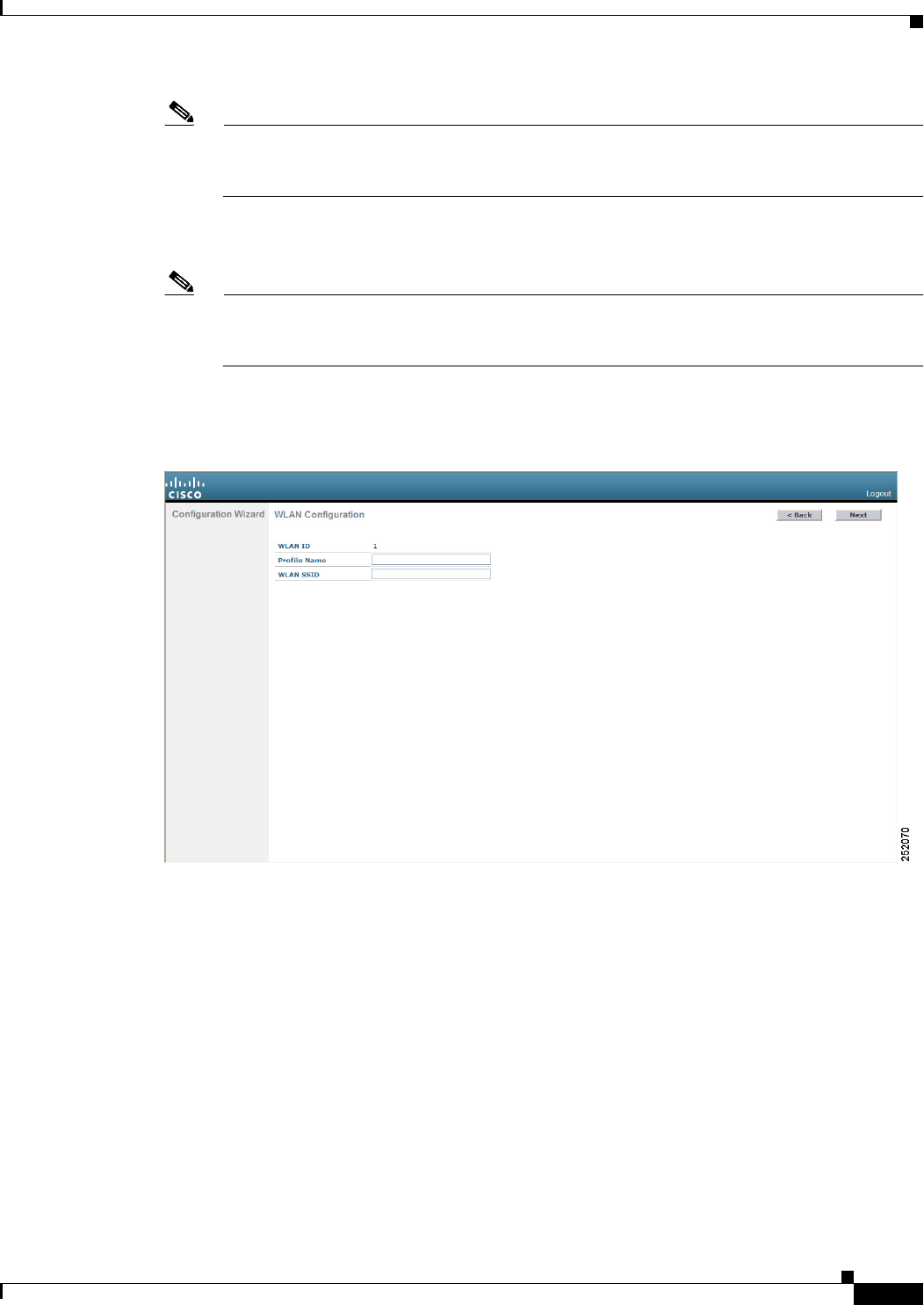
2-9
Cisco Wireless LAN Controller Configuration Guide
OL-21524-02
Chapter 2 Using the Web-Browser and CLI Interfaces
Using the Configuration Wizard
Note The virtual interface is used to support mobility management, DHCP relay, and embedded Layer
3 security such as guest web authentication and VPN termination. All controllers within a
mobility group must be configured with the same virtual interface IP address.
Step 33 In the DNS Host Name text box, enter the name of the Domain Name System (DNS) gateway used to
verify the source of certificates when Layer 3 web authorization is enabled.
Note To ensure connectivity and web authentication, the DNS server should always point to the virtual
interface. If a DNS host name is configured for the virtual interface, then the same DNS host
name must be configured on the DNS servers used by the client.
Step 34 Click Next. The WLAN Configuration screen appears (see Figure 2-8).
Figure 2-8 Configuration Wizard — WLAN Configuration Screen
Step 35 In the Profile Name text box, enter up to 32 alphanumeric characters for the profile name to be assigned
to this WLAN.
Step 36 In the WLAN SSID text box, enter up to 32 alphanumeric characters for the network name, or service
set identifier (SSID). The SSID enables basic functionality of the controller and allows access points that
have joined the controller to enable their radios.
Step 37 Click Next.
Step 38 When the following message appears, click OK:
Default Security applied to WLAN is: [WPA2(AES)][Auth(802.1x)]. You can change this after
the wizard is complete and the system is rebooted.
The RADIUS Server Configuration screen appears (see Figure 2-9).
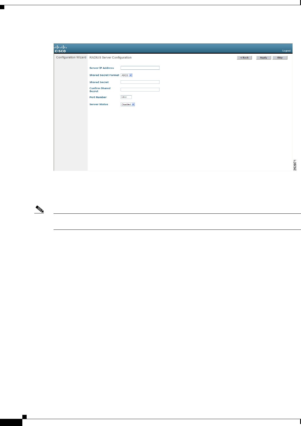
2-10
Cisco Wireless LAN Controller Configuration Guide
OL-21524-02
Chapter 2 Using the Web-Browser and CLI Interfaces
Using the Configuration Wizard
Figure 2-9 Configuration Wizard — RADIUS Server Configuration Screen
Step 39 In the Server IP Address text box, enter the IP address of the RADIUS server.
Step 40 From the Shared Secret Format drop-down list, choose ASCII or Hex to specify the format of the shared
secret.
Note Due to security reasons, the RADIUS shared secret key reverts to ASCII mode even if you have selected
HEX as the shared secret format from the Shared Secret Format drop-down list.
Step 41 In the Shared Secret and Confirm Shared Secret text boxes, enter the secret key used by the RADIUS
server.
Step 42 In the Port Number text box, enter the communication port of the RADIUS server. The default value is
1812.
Step 43 To enable the RADIUS server, choose Enabled from the Server Status drop-down list. To disable the
RADIUS server, leave this text box set to Disabled.
Step 44 Click Apply. The 802.11 Configuration screen appears (see Figure 2-10).

2-11
Cisco Wireless LAN Controller Configuration Guide
OL-21524-02
Chapter 2 Using the Web-Browser and CLI Interfaces
Using the Configuration Wizard
Figure 2-10 Configuration Wizard — 802.11 Configuration Screen
Step 45 To enable the 802.11a, 802.11b, and 802.11g lightweight access point networks, leave the 802.11a
Network Status, 802.11b Network Status, and 802.11g Network Status check boxes selected. To
disable support for any of these networks, unselect the check boxes.
Step 46 To enable the controller’s radio resource management (RRM) auto-RF feature, leave the Auto RF check
box selected. To disable support for the auto-RF feature, unselect this check box. See Chapter 13,
“Configuring Radio Resource Management,” for more information on RRM.
Note The auto-RF feature enables the controller to automatically form an RF group with other
controllers. The group dynamically elects a leader to optimize RRM parameter settings, such as
channel and transmit power assignment, for the group.
Step 47 Click Next. The Set Time screen appears (see Figure 2-11).
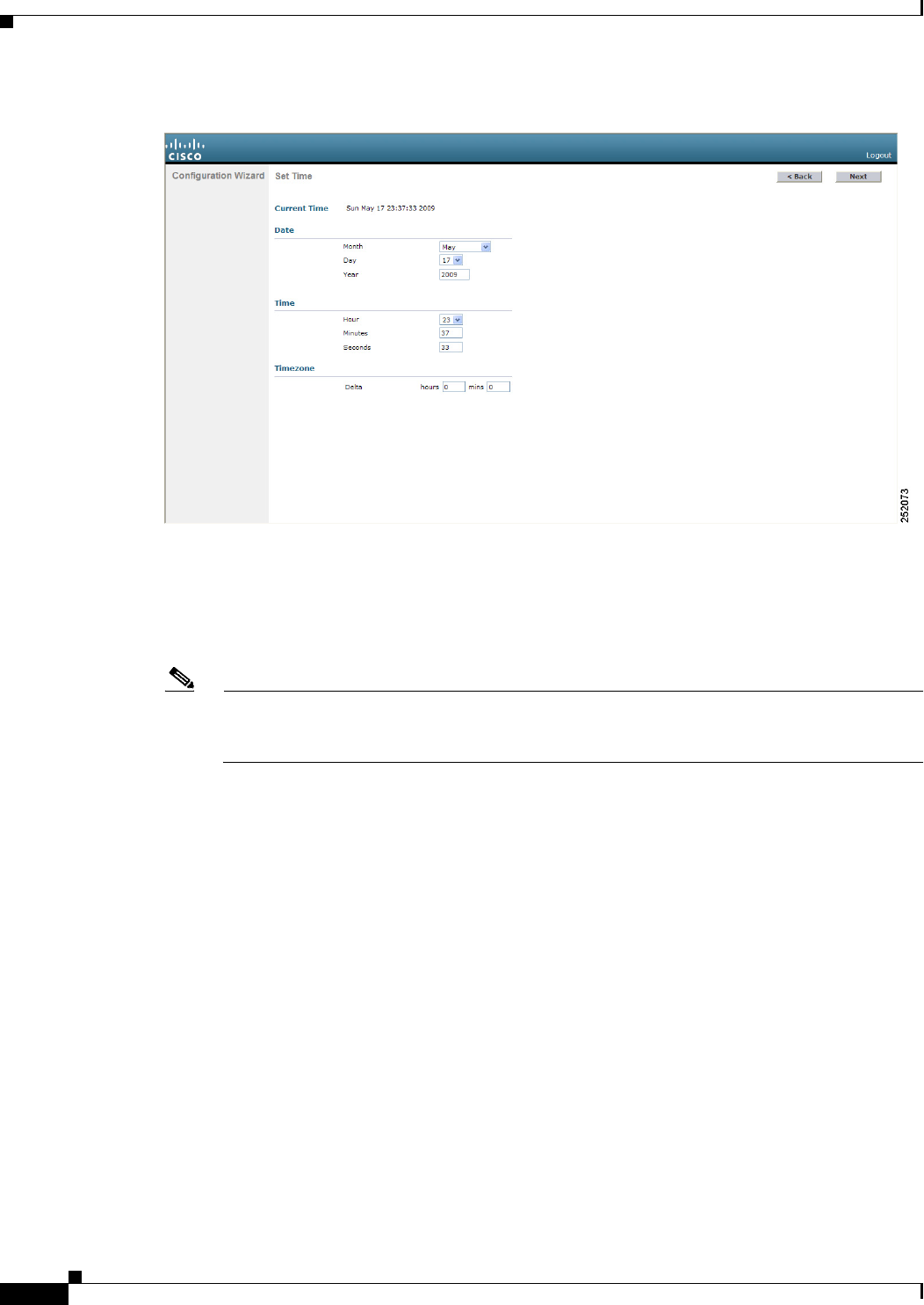
2-12
Cisco Wireless LAN Controller Configuration Guide
OL-21524-02
Chapter 2 Using the Web-Browser and CLI Interfaces
Using the Configuration Wizard
Figure 2-11 Configuration Wizard — Set Time Screen
Step 48 To manually configure the system time on your controller, enter the current date in Month/DD/YYYY
format and the current time in HH:MM:SS format.
Step 49 To manually set the time zone so that Daylight Saving Time (DST) is not set automatically, enter the
local hour difference from Greenwich Mean Time (GMT) in the Delta Hours text box and the local
minute difference from GMT in the Delta Mins text box.
Note When manually setting the time zone, enter the time difference of the local current time zone
with respect to GMT (+/–). For example, Pacific time in the United States is 8 hours behind
GMT. Therefore, it is entered as –8.
Step 50 Click Next. The Configuration Wizard Completed screen appears (see Figure 2-12).

2-13
Cisco Wireless LAN Controller Configuration Guide
OL-21524-02
Chapter 2 Using the Web-Browser and CLI Interfaces
Using the Configuration Wizard
Figure 2-12 Configuration Wizard — Configuration Wizard Completed Screen
Step 51 Click Save and Reboot to save your configuration and reboot the controller.
Step 52 When the following message appears, click OK:
Configuration will be saved and the controller will be rebooted. Click ok to confirm.
Step 53 The controller saves your configuration, reboots, and prompts you to log in. Follow the instructions in
the “Using the GUI” section on page 2-16 to log into the controller.
Using the CLI Configuration Wizard
Note The available options appear in brackets after each configuration parameter. The default value appears
in all uppercase letters.
Note If you enter an incorrect response, the controller provides you with an appropriate error message, such
as “Invalid Response,” and returns you to the wizard prompt.
Note Press the hyphen key if you ever need to return to the previous command line.

2-14
Cisco Wireless LAN Controller Configuration Guide
OL-21524-02
Chapter 2 Using the Web-Browser and CLI Interfaces
Using the Configuration Wizard
To configure the controller using the CLI configuration wizard, follow these steps:
Step 1 When prompted to terminate the AutoInstall process, enter yes. If you do not enter yes, the AutoInstall
process begins after 30 seconds.
Note The AutoInstall feature downloads a configuration file from a TFTP server and then loads the
configuration onto the controller automatically. See the “Using the AutoInstall Feature for
Controllers Without a Configuration” section on page 2-26 for more information.
Note The Cisco WiSM controllers do not support the AutoInstall feature.
Step 2 Enter the system name, which is the name that you want to assign to the controller. You can enter up to
31 ASCII characters.
Step 3 Enter the administrative username and password to be assigned to this controller. You can enter up to 24
ASCII characters for each.
Starting in release 7.0.116.0, the following password policy has been implemented:
• The password must contain characters from at least three of the following classes:
–
Lowercase letters
–
Uppercase letters
–
Digits
–
Special characters.
• No character in the password must be repeated more than three times consecutively.
• The new password must not be the same as the associated username and not be the username
reversed.
• The password must not be cisco, ocsic, or any variant obtained by changing the capitalization of
letters of the word Cisco. In addition, you cannot substitute 1, I, or ! for i, 0 for o, or $ for s.
Step 4 If you want the controller’s service-port interface to obtain an IP address from a DHCP server, enter
DHCP. If you do not want to use the service port or if you want to assign a static IP address to the service
port, enter none.
Note The service-port interface controls communications through the service port. Its IP address must
be on a different subnet from the management interface. This configuration enables you to
manage the controller directly or through a dedicated management network to ensure service
access during network downtime.
Step 5 If you entered none in Step 4, enter the IP address and netmask for the service-port interface on the next
two lines.
Step 6 Enable or disable link aggregation (LAG) by choosing yes or NO. See Chapter 3, “Configuring Ports and
Interfaces,” for more information on LAG.
Step 7 Enter the IP address of the management interface.

2-15
Cisco Wireless LAN Controller Configuration Guide
OL-21524-02
Chapter 2 Using the Web-Browser and CLI Interfaces
Using the Configuration Wizard
Note The management interface is the default interface for in-band management of the controller and
connectivity to enterprise services such as AAA servers.
Step 8 Enter the IP address of the management interface netmask.
Step 9 Enter the IP address of the default router.
Step 10 Enter the VLAN identifier of the management interface (either a valid VLAN identifier or 0 for an
untagged VLAN). The VLAN identifier should be set to match the switch interface configuration.
Step 11 Enter the IP address of the default DHCP server that will supply IP addresses to clients, the controller’s
management interface, and optionally, the service port interface.Enter the IP address of the AP-manager
interface.
Note This prompt does not appear for Cisco 5500 Series Controllers because you are not required to
configure an AP-manager interface. The management interface acts like an AP-manager
interface by default.
Step 12 Enter the IP address of the controller’s virtual interface. You should enter a fictitious, unassigned IP
address such as 1.1.1.1.
Note The virtual interface is used to support mobility management, DHCP relay, and embedded Layer
3 security such as guest web authentication and VPN termination. All controllers within a
mobility group must be configured with the same virtual interface IP address.
Step 13 If desired, enter the name of the mobility group/RF group to which you want the controller to belong.
Note Although the name that you enter here is assigned to both the mobility group and the RF group,
these groups are not identical. Both groups define clusters of controllers, but they have different
purposes. All of the controllers in an RF group are usually also in the same mobility group and
vice versa. However, a mobility group facilitates scalable, system-wide mobility and controller
redundancy while an RF group facilitates scalable, system-wide dynamic RF management. See
Chapter 13, “Configuring Radio Resource Management,” and Chapter 14, “Configuring
Mobility Groups,” for more information.
Step 14 Enter the network name or service set identifier (SSID). The SSID enables basic functionality of the
controller and allows access points that have joined the controller to enable their radios.
Step 15 Enter YES to allow clients to assign their own IP address or no to require clients to request an IP address
from a DHCP server.
Step 16 To configure a RADIUS server now, enter YES and then enter the IP address, communication port, and
secret key of the RADIUS server. Otherwise, enter no. If you enter no, the following message appears:
“Warning! The default WLAN security policy requires a RADIUS server. Please see the documentation
for more details.”
Step 17 Enter the code for the country in which the controller will be used.
Note Enter help to view the list of available country codes.

2-16
Cisco Wireless LAN Controller Configuration Guide
OL-21524-02
Chapter 2 Using the Web-Browser and CLI Interfaces
Using the GUI
Note You can enter more than one country code if you want to manage access points in multiple
countries from a single controller. To do so, separate the country codes with a comma (for
example, US,CA,MX). After the configuration wizard runs, you need to assign each access point
joined to the controller to a specific country. See the “Configuring Country Codes” section on
page 8-106 for instructions.
Step 18 Enable or disable the 802.11b, 802.11a, and 802.11g lightweight access point networks by entering YES
or no.
Step 19 Enable or disable the controller’s radio resource management (RRM) auto-RF feature by entering YES
or no. See Chapter 13, “Configuring Radio Resource Management,” for more information on RRM.
Note The auto-RF feature enables the controller to automatically form an RF group with other
controllers. The group dynamically elects a leader to optimize RRM parameter settings, such as
channel and transmit power assignment, for the group.
Step 20 If you want the controller to receive its time setting from an external Network Time Protocol (NTP)
server when it powers up, enter YES to configure an NTP server. Otherwise, enter no.
Note The controller network module installed in a Cisco Integrated Services Router does not have a
battery and cannot save a time setting. Therefore, it must receive a time setting from an external
NTP server when it powers up.
Step 21 If you entered no in Step 20 and want to manually configure the system time on your controller now,
enter YES. If you do not want to configure the system time now, enter no.
Step 22 If you entered YES in Step 21, enter the current date in MM/DD/YY format and the current time in
HH:MM:SS format.
Step 23 When prompted to verify that the configuration is correct, enter yes or NO.
The controller saves your configuration, reboots, and prompts you to log in. Follow the instructions in
the “Using the CLI” section on page 2-22 to log into the controller.
Using the GUI
A web browser, or graphical user interface (GUI), is built into each controller. It allows up to five users
to simultaneously browse into the controller HTTP or HTTPS (HTTP + SSL) management pages to
configure parameters and monitor the operational status for the controller and its associated access
points.
Note We recommend that you enable the HTTPS interface and disable the HTTP interface to ensure more
robust security for your Cisco UWN solution.

2-17
Cisco Wireless LAN Controller Configuration Guide
OL-21524-02
Chapter 2 Using the Web-Browser and CLI Interfaces
Using the GUI
Guidelines for Using the GUI
Follow these guidelines when using the controller GUI:
• The GUI must be used on a PC running Windows XP SP1 (or later) or Windows 2000 SP4 (or later).
• The GUI is fully compatible with Microsoft Internet Explorer version 6.0 SP1 (or later) or Mozilla
Firefox 2.0.0.11 (or later).
Note Opera and Netscape are not supported.
Note Internet Explorer 6.0 SP1 (or later) and Mozilla Firefox 2.0.0.11 (or later) are the only
browsers supported for accessing the controller GUI and for using web authentication.
• You can use either the service port interface or the management interface to access the GUI. We
recommend that you use the service-port interface. See Chapter 3, “Configuring Ports and
Interfaces,” for instructions on configuring the service port interface.
• Click Help at the top of any page in the GUI to display online help. You might need to disable your
browser’s pop-up blocker to view the online help.
Logging into the GUI
To log into the controller GUI, follow these steps:
Step 1 Enter the controller IP address in your browser’s address line. For a secure connection, enter
https://ip-address. For a less secure connection, enter http://ip-address.
Note See the “Using the GUI to Enable Web and Secure Web Modes” section on page 2-18 for
instructions on setting up HTTPS.
Step 2 When prompted, enter a valid username and password and click OK. The controller Summary page
appears.
Note The administrative username and password that you created in the configuration wizard are case
sensitive. The default username is admin, and the default password is admin.
Logging Out of the GUI
To log out of the controller GUI, follow these steps:
Step 1 Click Logout in the top right corner of the page.
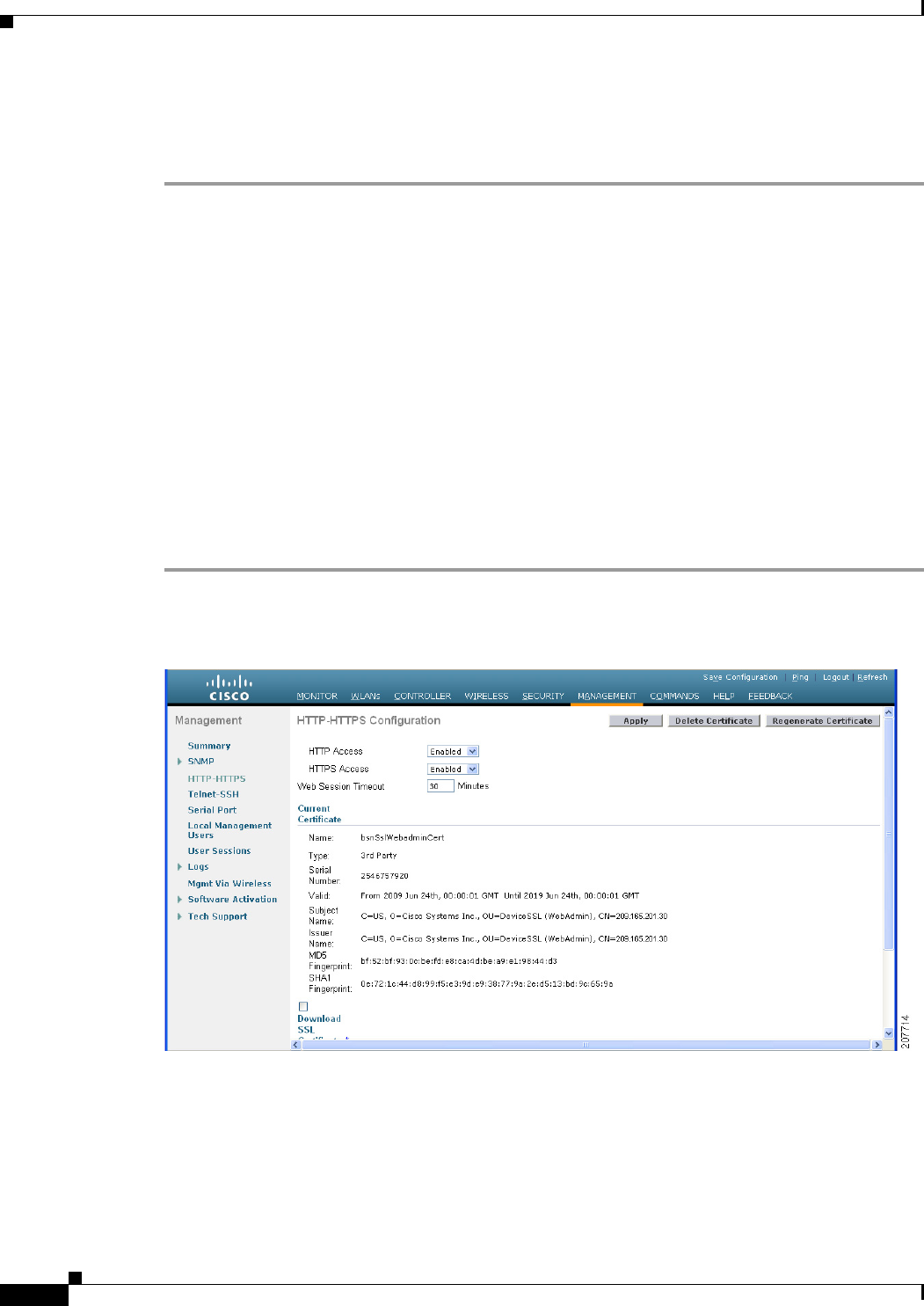
2-18
Cisco Wireless LAN Controller Configuration Guide
OL-21524-02
Chapter 2 Using the Web-Browser and CLI Interfaces
Using the GUI
Step 2 Click Close to complete the logoff process and prevent unauthorized users from accessing the controller
GUI.
Step 3 When prompted to confirm your decision, click Yes .
Enabling Web and Secure Web Modes
This section provides instructions for enabling the distribution system port as a web port (using HTTP)
or as a secure web port (using HTTPS). You can protect communication with the GUI by enabling
HTTPS. HTTPS protects HTTP browser sessions by using the Secure Sockets Layer (SSL) protocol.
When you enable HTTPS, the controller generates its own local web administration SSL certificate and
automatically applies it to the GUI. You also have the option of downloading an externally generated
certificate.
You can configure web and secure web mode using the controller GUI or CLI.
Using the GUI to Enable Web and Secure Web Modes
To enable web mode, secure web mode, or both using the controller GUI, follow these steps:
Step 1 Choose Management > HTTP to open the HTTP Configuration page (see Figure 2-13).
Figure 2-13 HTTP Configuration Page
Step 2 To enable web mode, which allows users to access the controller GUI using “http://ip-address,” choose
Enabled from the HTTP Access drop-down list. Otherwise, choose Disabled. The default value is
Disabled. Web mode is not a secure connection.

2-19
Cisco Wireless LAN Controller Configuration Guide
OL-21524-02
Chapter 2 Using the Web-Browser and CLI Interfaces
Using the GUI
Step 3 To enable secure web mode, which allows users to access the controller GUI using “https://ip-address,”
choose Enabled from the HTTPS Access drop-down list. Otherwise, choose Disabled. The default value
is Enabled. Secure web mode is a secure connection.
Step 4 In the Web Session Timeout text box, enter the amount of time (in minutes) before the web session times
out due to inactivity. You can enter a value between 30 and 160 minutes (inclusive), and the default value
is 30 minutes.
Step 5 Click Apply to commit your changes.
Step 6 If you enabled secure web mode in Step 3, the controller generates a local web administration SSL
certificate and automatically applies it to the GUI. The details of the current certificate appear in the
middle of the HTTP Configuration page (see Figure 2-13).
Note If you want to download your own SSL certificate to the controller, follow the instructions in the
“Loading an Externally Generated SSL Certificate” section on page 2-20.
Note If desired, you can delete the current certificate by clicking Delete Certificate and have the
controller generate a new certificate by clicking Regenerate Certificate.
Step 7 Click Save Configuration to save your changes.
Using the CLI to Enable Web and Secure Web Modes
To enable web mode, secure web mode, or both using the controller CLI, follow these steps:
Step 1 To enable or disable web mode, enter this command:
config network webmode {enable | disable}
This command allows users to access the controller GUI using “http://ip-address.” The default value is
disabled. Web mode is not a secure connection.
Step 2 To enable or disable secure web mode, enter this command:
config network secureweb {enable | disable}
This command allows users to access the controller GUI using “https://ip-address.” The default value is
enabled. Secure web mode is a secure connection.
Step 3 To enable or disable secure web mode with increased security, enter this command:
config network secureweb cipher-option high {enable | disable}
This command allows users to access the controller GUI using “https://ip-address” but only from
browsers that support 128-bit (or larger) ciphers. The default value is disabled.
Step 4 To enable or disable SSLv2 for web administration, enter this command:
config network secureweb cipher-option sslv2 {enable | disable}
If you disable SSLv2, users cannot connect using a browser configured with SSLv2 only. They must use
a browser that is configured to use a more secure protocol such as SSLv3 or later. The default value is
enabled.
Step 5 To verify that the controller has generated a certificate, enter this command:

2-20
Cisco Wireless LAN Controller Configuration Guide
OL-21524-02
Chapter 2 Using the Web-Browser and CLI Interfaces
Using the GUI
show certificate summary
Information similar to the following appears:
Web Administration Certificate................. Locally Generated
Web Authentication Certificate................. Locally Generated
Certificate compatibility mode:................ off
Note If you want to download your own SSL certificate to the controller, follow the instructions in the
“Loading an Externally Generated SSL Certificate” section on page 2-20.
Step 6 (Optional) If you need to generate a new certificate, enter this command:
config certificate generate webadmin
After a few seconds, the controller verifies that the certificate has been generated.
Step 7 To save the SSL certificate, key, and secure web password to nonvolatile RAM (NVRAM) so that your
changes are retained across reboots, enter this command:
save config
Step 8 To reboot the controller, enter this command:
reset system
Loading an Externally Generated SSL Certificate
You can use a TFTP server to download an externally generated SSL certificate to the controller. Follow
these guidelines for using TFTP:
• If you load the certificate through the service port, the TFTP server must be on the same subnet as
the controller because the service port is not routable, or you must create static routes on the
controller. Also, if you load the certificate through the distribution system network port, the TFTP
server can be on any subnet.
• A third-party TFTP server cannot run on the same PC as the Cisco WCS because the WCS built-in
TFTP server and the third-party TFTP server require the same communication port.
Note Chained certificates are supported for web authentication only and not for the management certificate.
Note Every HTTPS certificate contains an embedded RSA key. The length of the key can vary from 512 bits,
which is relatively insecure, to thousands of bits, which is very secure. When you obtain a new certificate
from a Certificate Authority, make sure that the RSA key embedded in the certificate is at least 768 bits
long.
Using the GUI to Load an SSL Certificate
To load an externally generated SSL certificate using the controller GUI, follow these steps:
Step 1 On the HTTP Configuration page, select the Download SSL Certificate check box (see Figure 2-14).
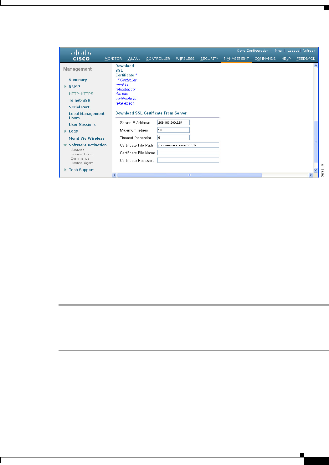
2-21
Cisco Wireless LAN Controller Configuration Guide
OL-21524-02
Chapter 2 Using the Web-Browser and CLI Interfaces
Using the GUI
Figure 2-14 HTTP Configuration Page
Step 2 In the Server IP Address text box, enter the IP address of the TFTP server.
Step 3 In the Maximum Retries text box, enter the maximum number of times that the TFTP server attempts to
download the certificate.
Step 4 In the Timeout text box, enter the amount of time (in seconds) that the TFTP server attempts to download
the certificate.
Step 5 In the Certificate File Path text box, enter the directory path of the certificate.
Step 6 In the Certificate File Name text box, enter the name of the certificate (webadmincert_name.pem).
Step 7 (Optional) In the Certificate Password text box, enter a password to encrypt the certificate.
Step 8 Click Apply to commit your changes.
Step 9 Click Save Configuration to save your changes.
Step 10 To reboot the controller for your changes to take effect, choose Commands > Reboot > Reboot > Save
and Reboot.
Using the CLI to Load an SSL Certificate
To load an externally generated SSL certificate using the controller CLI, follow these steps:
Step 1 Use a password to encrypt the HTTPS certificate in a .PEM-encoded file. The PEM-encoded file is called
a web administration certificate file (webadmincert_name.pem).
Step 2 Move the webadmincert_name.pem file to the default directory on your TFTP server.
Step 3 To view the current download settings, enter this command and answer n to the prompt:
transfer download start
Information similar to the following appears:
Mode........................................... TFTP
Data Type...................................... Admin Cert
TFTP Server IP................................. xxx.xxx.xxx.xxx

2-22
Cisco Wireless LAN Controller Configuration Guide
OL-21524-02
Chapter 2 Using the Web-Browser and CLI Interfaces
Using the CLI
TFTP Path...................................... <directory path>
TFTP Filename..................................
Are you sure you want to start? (y/n) n
Transfer Canceled
Step 4 Use these commands to change the download settings:
transfer download mode tftp
transfer download datatype webauthcert
transfer download serverip TFTP_server IP_address
transfer download path absolute_TFTP_server_path_to_the_update_file
transfer download filename webadmincert_name.pem
Step 5 To set the password for the .PEM file so that the operating system can decrypt the web administration
SSL key and certificate, enter this command:
transfer download certpassword private_key_password
Step 6 To confirm the current download settings and start the certificate and key download, enter this command
and answer y to the prompt:
transfer download start
Information similar to the following appears:
Mode........................................... TFTP
Data Type...................................... Site Cert
TFTP Server IP................................. xxx.xxx.xxx.xxx
TFTP Path...................................... directory path
TFTP Filename.................................. webadmincert_name
Are you sure you want to start? (y/n) y
TFTP Webadmin cert transfer starting.
Certificate installed.
Please restart the switch (reset system) to use the new certificate.
Step 7 To save the SSL certificate, key, and secure web password to NVRAM so that your changes are retained
across reboots, enter this command:
save config
Step 8 To reboot the controller, enter this command:
reset system
Using the CLI
A Cisco UWN solution command-line interface (CLI) is built into each controller. The CLI allows you
to use a VT-100 terminal emulation program to locally or remotely configure, monitor, and control
individual controllers and its associated lightweight access points. The CLI is a simple text-based,
tree-structured interface that allows up to five users with Telnet-capable terminal emulation programs to
access the controller.
Note See the Cisco Wireless LAN Controller Command Reference for information on specific commands.

2-23
Cisco Wireless LAN Controller Configuration Guide
OL-21524-02
Chapter 2 Using the Web-Browser and CLI Interfaces
Using the CLI
Note If you want to input any strings from the XML configuration into CLI commands, you must enclose the
strings in quotation marks.
Logging into the CLI
You access the controller CLI using one of two methods:
• A direct serial connection to the controller console port
• A remote console session over Ethernet through the preconfigured service port or the distribution
system ports
Before you log into the CLI, configure your connectivity and environment variables based on the type
of connection you use.
Using a Local Serial Connection
You need these items to connect to the serial port:
• A PC that is running a VT-100 terminal emulation program (such as HyperTerminal, ProComm,
Minicom, or Tip)
• A null-modem serial cable
To log into the controller CLI through the serial port, follow these steps:
Step 1 Connect one end of a null-modem serial cable to the controller’s console port and the other end to your
PC’s serial port.
Note On Cisco 5500 Series Controllers, you can use either the RJ-45 console port or the USB console
port. If you use the USB console port, plug the 5-pin mini Type B connector into the controller’s
USB console port and the other end of the cable into the PC’s USB Type A port. The first time
that you connect a Windows PC to the USB console port, you are prompted to install the USB
console driver. Follow the installation prompts to install the driver. The USB console driver maps
to a COM port on your PC; you then need to map the terminal emulator application to the COM
port.
Step 2 Start the PC’s VT-100 terminal emulation program.
Step 3 Configure the terminal emulation program for these parameters:
• 9600 baud
• 8 data bits
• 1 stop bit
• No parity
• No hardware flow control

2-24
Cisco Wireless LAN Controller Configuration Guide
OL-21524-02
Chapter 2 Using the Web-Browser and CLI Interfaces
Using the CLI
Note The controller serial port is set for a 9600 baud rate and a short timeout. If you would like to
change either of these values, enter config serial baudrate baudrate and config serial timeout
timeout to make your changes. If you enter config serial timeout 0, serial sessions never time
out.
Step 4 When prompted, enter a valid username and password to log into the controller. The administrative
username and password that you created in the configuration wizard are case sensitive.
Note The default username is admin, and the default password is admin.
The CLI displays the root level system prompt:
#(system prompt)>
Note The system prompt can be any alphanumeric string up to 31 characters. You can change it by
entering the config prompt command.
Using a Remote Ethernet Connection
You need these items to connect to a controller remotely:
• A PC with access to the controller over the Ethernet network
• The IP address of the controller
• A VT-100 terminal emulation program or a DOS shell for the Telnet session
Note By default, controllers block Telnet sessions. You must use a local connection to the serial port to enable
Telnet sessions. See the “Configuring Telnet and SSH Sessions” section on page 2-34 for information on
enabling Telnet sessions.
To log into the controller CLI through a remote Ethernet connection, follow these steps:
Step 1 Verify that your VT-100 terminal emulation program or DOS shell interface is configured with these
parameters:
• Ethernet address
• Port 23
Step 2 Use the controller IP address to Telnet to the CLI.
Step 3 When prompted, enter a valid username and password to log into the controller. The administrative
username and password that you created in the configuration wizard are case sensitive.
Note The default username is admin, and the default password is admin.

2-25
Cisco Wireless LAN Controller Configuration Guide
OL-21524-02
Chapter 2 Using the Web-Browser and CLI Interfaces
Using the CLI
The CLI displays the root level system prompt:
#(system prompt)>
Note The system prompt can be any alphanumeric string up to 31 characters. You can change it by
entering the config prompt command.
Logging Out of the CLI
When you finish using the CLI, navigate to the root level and enter logout. The system prompts you to
save any changes you made to the volatile RAM.
Note The CLI automatically logs you out without saving any changes after 5 minutes of inactivity. You can
set the automatic logout from 0 (never log out) to 160 minutes using the config serial timeout command.
Navigating the CLI
The CLI is organized around five levels:
Root Level
Level 2
Level 3
Level 4
Level 5
When you log into the CLI, you are at the root level. From the root level, you can enter any full command
without first navigating to the correct command level. Table 2-1 lists commands you use to navigate the
CLI and to perform common tasks.
Ta b l e 2-1 Commands for CLI Navigation and Common Tasks
Command Action
help At the root level, view system wide navigation
commands
?View commands available at the current level
command ?View parameters for a specific command
exit Move down one level
Ctrl-Z Return from any level to the root level
save config At the root level, save configuration changes from
active working RAM to nonvolatile RAM
(NVRAM) so they are retained after reboot
reset system At the root level, reset the controller without
logging out

2-26
Cisco Wireless LAN Controller Configuration Guide
OL-21524-02
Chapter 2 Using the Web-Browser and CLI Interfaces
Using the AutoInstall Feature for Controllers Without a Configuration
Using the AutoInstall Feature for Controllers Without a
Configuration
When you boot up a controller that does not have a configuration, the AutoInstall feature can download
a configuration file from a TFTP server and then load the configuration onto the controller automatically.
Note The Cisco WiSM controllers do not support the AutoInstall feature.
Overview of AutoInstall
If you create a configuration file on a controller that is already on the network (or through a WCS filter),
place that configuration file on a TFTP server, and configure a DHCP server so that a new controller can
get an IP address and TFTP server information, the AutoInstall feature can obtain the configuration file
for the new controller automatically.
When the controller boots, the AutoInstall process starts. The controller does not take any action until
AutoInstall is notified that the configuration wizard has started. If the wizard has not started, the
controller has a valid configuration.
If AutoInstall is notified that the configuration wizard has started (which means that the controller does
not have a configuration), AutoInstall waits for an additional 30 seconds. This time period gives you an
opportunity to respond to the first prompt from the configuration wizard:
Would you like to terminate autoinstall? [yes]:
When the 30-second abort timeout expires, AutoInstall starts the DHCP client. You can abort the
AutoInstall task even after this 30-second timeout if you enter Ye s at the prompt. However, AutoInstall
cannot be aborted if the TFTP task has locked the flash and is in the process of downloading and
installing a valid configuration file.
Obtaining an IP Address Through DHCP and Downloading a Configuration File
from a TFTP Server
AutoInstall uses the following interfaces:
• Cisco 5500 and 4400 Series Controllers
–
eth0—Service port (untagged)
–
dtl0—Gigabit port 1 through the NPU (untagged)
• Cisco 2100 Series Controller
–
dtl0—FastEthernet port 1 (untagged)
AutoInstall attempts to obtain an IP address from the DHCP server until the DHCP process is successful
or until you abort the AutoInstall process. The first interface to successfully obtain an IP address from
the DHCP server registers with the AutoInstall task. The registration of this interface causes AutoInstall
to begin the process of obtaining TFTP server information and downloading the configuration file.

2-27
Cisco Wireless LAN Controller Configuration Guide
OL-21524-02
Chapter 2 Using the Web-Browser and CLI Interfaces
Using the AutoInstall Feature for Controllers Without a Configuration
Following the acquisition of the DHCP IP address for an interface, AutoInstall begins a short sequence
of events to determine the host name of the controller and the IP address of the TFTP server. Each phase
of this sequence gives preference to explicitly configured information over default or implied
information and to explicit host names over explicit IP addresses.
The process is as follows:
• If at least one Domain Name System (DNS) server IP address is learned through DHCP, AutoInstall
creates a /etc/resolv.conf file. This file includes the domain name and the list of DNS servers that
have been received. The Domain Name Server option provides the list of DNS servers, and the
Domain Name option provides the domain name.
• If the domain servers are not on the same subnet as the controller, static route entries are installed
for each domain server. These static routes point to the gateway that is learned through the DHCP
Router option.
• The host name of the controller is determined in this order by one of the following:
–
If the DHCP Host Name option was received, this information (truncated at the first period [.])
is used as the host name for the controller.
–
A reverse DNS lookup is performed on the controller IP address. If DNS returns a hostname,
this name (truncated at the first period [.]) is used as the hostname for the controller.
• The IP address of the TFTP server is determined in this order by one of the following:
–
If AutoInstall received the DHCP TFTP Server Name option, AutoInstall performs a DNS
lookup on this server name. If the DNS lookup is successful, the returned IP address is used as
the IP address of the TFTP server.
–
If the DHCP Server Host Name (sname) text box is valid, AutoInstall performs a DNS lookup
on this name. If the DNS lookup is successful, the IP address that is returned is used as the IP
address of the TFTP server.
–
If AutoInstall received the DHCP TFTP Server Address option, this address is used as the IP
address of the TFTP server.
–
AutoInstall performs a DNS lookup on the default TFTP server name (cisco-wlc-tftp). If the
DNS lookup is successful, the IP address that is received is used as the IP address of the TFTP
server.
–
If the DHCP server IP address (siaddr) text box is nonzero, this address is used as the IP address
of the TFTP server.
–
The limited broadcast address (255.255.255.255) is used as the IP address of the TFTP server.
• If the TFTP server is not on the same subnet as the controller, a static route (/32) is installed for the
IP address of the TFTP server. This static route points to the gateway that is learned through the
DHCP Router option.
Note For more information on configuring DHCP on a controller, See the “Configuring DHCP” section on
page 7-10.
Note For more information on configuring a TFTP server on a controller, see Chapter 10, “Managing
Controller Software and Configurations.”

2-28
Cisco Wireless LAN Controller Configuration Guide
OL-21524-02
Chapter 2 Using the Web-Browser and CLI Interfaces
Using the AutoInstall Feature for Controllers Without a Configuration
Note For more information on configuring DHCP and TFTP servers through WCS, see Chapter 10 of the
Cisco Wireless Control System Configuration Guide, Release 7.0.172.0.
Selecting a Configuration File
After the hostname and TFTP server have been determined, AutoInstall attempts to download a
configuration file. AutoInstall performs three full download iterations on each interface that obtains a
DHCP IP address. For example, if a Cisco 4400 Series Controller obtains DHCP IP addresses on both
eth0 and dtl0, each interface tries to download a configuration. If the interface cannot download a
configuration file successfully after three attempts, the interface does not attempt further.
The first configuration file that is downloaded and installed successfully triggers a reboot of the
controller. After the reboot, the controller runs the newly downloaded configuration.
AutoInstall searches for configuration files in the order in which the names are listed:
• The filename that is provided by the DHCP Boot File Name option
• The filename that is provided by the DHCP File text box
• host name-confg
• host name.cfg
• base MAC address-confg (for example, 0011.2233.4455-confg)
• serial number-confg
• ciscowlc-confg
• ciscowlc.cfg
AutoInstall runs through this list until it finds a configuration file. It stops running if it does not find a
configuration file after it cycles through this list three times on each registered interface.
Note The downloaded configuration file can be a complete configuration, or it can be a minimal configuration
that provides enough information for the controller to be managed by WCS. Full configuration can then
be deployed directly from WCS.
Note For information about creating and uploading a configuration file that AutoInstall can obtain from a
TFTP server, see Chapter 10, “Managing Controller Software and Configurations.”
Note WCS release 5.0 and later releases provide AutoInstall capabilities for controllers. A WCS administrator
can create a filter that includes the host name, the MAC address, or the serial number of the controller
and associate a group of templates (a configuration group) to this filter rule. WCS pushes the initial
configuration to the controller when the controller boots up initially. After the controller is discovered,
WCS pushes the templates that are defined in the configuration group. For more information about the
AutoInstall feature and WCS, see Chapter 15 of the Cisco Wireless Control System Configuration Guide,
Release 7.0.172.0.

2-29
Cisco Wireless LAN Controller Configuration Guide
OL-21524-02
Chapter 2 Using the Web-Browser and CLI Interfaces
Managing the System Date and Time
Example of AutoInstall Operation
The following is an example of an AutoInstall process from start to finish:
Welcome to the Cisco Wizard Configuration Tool
Use the '-' character to backup
Would you like to terminate autoinstall? [yes]:
AUTO-INSTALL: starting now...
AUTO-INSTALL: interface 'service-port' - setting DHCP TFTP Filename ==> 'abcd-confg'
AUTO-INSTALL: interface 'service-port' - setting DHCP TFTP Server IP ==> 1.100.108.2
AUTO-INSTALL: interface 'service-port' - setting DHCP siaddr ==> 1.100.108.2
AUTO-INSTALL: interface 'service-port' - setting DHCP Domain Server[0] ==> 1.100.108.2
AUTO-INSTALL: interface 'service-port' - setting DHCP Domain Name ==> 'engtest.com'
AUTO-INSTALL: interface 'service-port' - setting DHCP yiaddr ==> 172.19.29.253
AUTO-INSTALL: interface 'service-port' - setting DHCP Netmask ==> 255.255.255.0
AUTO-INSTALL: interface 'service-port' - setting DHCP Gateway ==> 172.19.29.1
AUTO-INSTALL: interface 'service-port' registered
AUTO-INSTALL: interation 1 -- interface 'service-port'
AUTO-INSTALL: DNS reverse lookup 172.19.29.253 ===> 'wlc-1'
AUTO-INSTALL: hostname 'wlc-1'
AUTO-INSTALL: TFTP server 1.100.108.2 (from DHCP Option 150)
AUTO-INSTALL: attempting download of 'abcd-confg'
AUTO-INSTALL: TFTP status - 'TFTP Config transfer starting.' (2)
AUTO-INSTALL: interface 'management' - setting DHCP file ==> 'bootfile1'
AUTO-INSTALL: interface 'management' - setting DHCP TFTP Filename ==> 'bootfile2-confg'
AUTO-INSTALL: interface 'management' - setting DHCP siaddr ==> 1.100.108.2
AUTO-INSTALL: interface 'management' - setting DHCP Domain Server[0] ==> 1.100.108.2
AUTO-INSTALL: interface 'management' - setting DHCP Domain Server[1] ==> 1.100.108.3
AUTO-INSTALL: interface 'management' - setting DHCP Domain Server[2] ==> 1.100.108.4
AUTO-INSTALL: interface 'management' - setting DHCP Domain Name ==> 'engtest.com'
AUTO-INSTALL: interface 'management' - setting DHCP yiaddr ==> 1.100.108.238
AUTO-INSTALL: interface 'management' - setting DHCP Netmask ==> 255.255.254.0
AUTO-INSTALL: interface 'management' - setting DHCP Gateway ==> 1.100.108.1
AUTO-INSTALL: interface 'management' registered
AUTO-INSTALL: TFTP status - 'Config file transfer failed - Error from server: File not
found' (3)
AUTO-INSTALL: attempting download of 'wlc-1-confg'
AUTO-INSTALL: TFTP status - 'TFTP Config transfer starting.' (2)
AUTO-INSTALL: TFTP status - 'TFTP receive complete... updating configuration.' (2)
AUTO-INSTALL: TFTP status - 'TFTP receive complete... storing in flash.' (2)
AUTO-INSTALL: TFTP status - 'System being reset.' (2)
Resetting system
Managing the System Date and Time
If you did not configure the system date and time through the configuration wizard or if you want to
change your configuration, you can follow the instructions in this section to configure the controller to
obtain the date and time from a Network Time Protocol (NTP) server or to configure the date and time
manually. Greenwich Mean Time (GMT) is used as the standard for setting the time zone on the
controller.
Note If you are configuring wIPS, you must set the controller time zone to UTC.

2-30
Cisco Wireless LAN Controller Configuration Guide
OL-21524-02
Chapter 2 Using the Web-Browser and CLI Interfaces
Managing the System Date and Time
Note Cisco Aironet lightweight access points might not connect to the controller if the date and time are not
set properly. Set the current date and time on the controller before allowing the access points to connect
to it.
Configuring an NTP Server to Obtain the Date and Time
Each NTP server IP address is added to the controller database. Each controller searches for an NTP
server and obtains the current time upon reboot and at each user-defined polling interval (daily to
weekly).
Use these commands to configure an NTP server to obtain the date and time:
• To specify the NTP server for the controller, enter this command:
config time ntp server index ip_address
• To specify the polling interval (in seconds), enter this command:
config time ntp interval
Configuring NTP Authentication
Starting in the 7.0.116.0 release, you can configure an authentication channel between the controller and
the NTP server.
Using the GUI to Configure NTP Authentication
To configure NTP authentication using the controller GUI, perform these steps:
Step 1 Choose Controller > NTP > Servers to open the NTP Servers page.
Step 2 Click New to add an NTP server.
The NTP Servers > New page appears
Step 3 Select a server priority from the Server Index (Priority) from the drop-down list.
Step 4 Enter the NTP server IP Address in the Server IP Address text box.
Step 5 Enable NTP server authentication by selecting the NTP Server Authentication check box.
Step 6 Click Apply.
Step 7 Choose Controller > NTP > Keys
Step 8 Click New to create a key.
Step 9 Enter the key index in the Key Index text box.
Step 10 Select the key format from the Key Format drop-down list.
Step 11 Enter the Key in the Key text box.
Step 12 Click Apply.

2-31
Cisco Wireless LAN Controller Configuration Guide
OL-21524-02
Chapter 2 Using the Web-Browser and CLI Interfaces
Managing the System Date and Time
Using the CLI to Configure NTP Authentication
To configure NTP authentication using the CLI, use the following commands:
• To enable or disable NTP authentication, use the following command:
Note By default MD5 is used.
–
config time ntp auth enable <server-index> <key-index>
–
config time ntp auth disable <server-index>
–
config time ntp key-auth add <key-index> md5 <key-format> <key>
• To delete an authentication key, use the following command:
config time ntp key-auth delete <key-index>
• To view the list of NTP key Indices, use the following command:
show ntp-keys
Configuring the Date and Time Manually
This section describes how to configure the date and time manually using the controller GUI or CLI.
Using the GUI to Configure the Date and Time
To configure the local date and time using the controller GUI, follow these steps:
Step 1 Choose Commands > Set Time to open the Set Time page (see Figure 2-15).
Figure 2-15 Set Time Page
The current date and time appear at the top of the page.

2-32
Cisco Wireless LAN Controller Configuration Guide
OL-21524-02
Chapter 2 Using the Web-Browser and CLI Interfaces
Managing the System Date and Time
Step 2 In the Timezone area, choose your local time zone from the Location drop-down list.
Note When you choose a time zone that uses Daylight Saving Time (DST), the controller
automatically sets its system clock to reflect the time change when DST occurs. In the United
States, DST starts on the second Sunday in March and ends on the first Sunday in November.
Note You cannot set the time zone delta on the controller GUI. However, if you do so on the controller
CLI, the change is reflected in the Delta Hours and Mins text boxes on the controller GUI.
Step 3 Click Set Timezone to apply your changes.
Step 4 In the Date area, choose the current local month and day from the Month and Day drop-down lists, and
enter the year in the Year text box.
Step 5 In the Time area, choose the current local hour from the Hour drop-down list, and enter the minutes and
seconds in the Minutes and Seconds text boxes.
Note If you change the time zone location after setting the date and time, the values in the Time area
are updated to reflect the time in the new time zone location. For example, if the controller is
currently configured for noon Eastern time and you change the time zone to Pacific time, the
time automatically changes to 9:00 a.m.
Step 6 Click Set Date and Time to apply your changes.
Step 7 Click Save Configuration to save your changes.
Using the CLI to Configure the Date and Time
To configure the local date and time using the controller CLI, follow these steps:
Step 1 To configure the current local date and time in GMT on the controller, enter this command:
config time manual mm/dd/yy hh:mm:ss
Note When setting the time, the current local time is entered in terms of GMT and as a value between
00:00 and 24:00. For example, if it is 8:00 a.m. Pacific time in the United States, you would enter
16:00 because the Pacific time zone is 8 hours behind GMT.
Step 2 Perform one of the following to set the time zone for the controller:
• To set the time zone location in order to have Daylight Saving Time (DST) set automatically when
it occurs, enter this command:
config time timezone location location_index
where location_index is a number representing one of the following time zone locations:
1. (GMT-12:00) International Date Line West
2. (GMT-11:00) Samoa

2-33
Cisco Wireless LAN Controller Configuration Guide
OL-21524-02
Chapter 2 Using the Web-Browser and CLI Interfaces
Managing the System Date and Time
3. (GMT-10:00) Hawaii
4. (GMT-9:00) Alaska
5. (GMT-8:00) Pacific Time (US and Canada)
6. (GMT-7:00) Mountain Time (US and Canada)
7. (GMT-6:00) Central Time (US and Canada)
8. (GMT-5:00) Eastern Time (US and Canada)
9. (GMT-4:00) Atlantic Time (Canada)
10. (GMT-3:00) Buenos Aires (Argentina)
11. (GMT-2:00) Mid-Atlantic
12. (GMT-1:00) Azores
13. (GMT) London, Lisbon, Dublin, Edinburgh (default value)
14. (GMT +1:00) Amsterdam, Berlin, Rome, Vienna
15. (GMT +2:00) Jerusalem
16. (GMT +3:00) Baghdad
17. (GMT +4:00) Muscat, Abu Dhabi
18. (GMT +4:30) Kabul
19. (GMT +5:00) Karachi, Islamabad, Tashkent
20. (GMT +5:30) Colombo, Kolkata, Mumbai, New Delhi
21. (GMT +5:45) Katmandu
22. (GMT +6:00) Almaty, Novosibirsk
23. (GMT +6:30) Rangoon
24. (GMT +7:00) Saigon, Hanoi, Bangkok, Jakarta
25. (GMT +8:00) Hong Kong, Beijing, Chongqing
26. (GMT +9:00) Tokyo, Osaka, Sapporo
27. (GMT +9:30) Darwin
28. (GMT+10:00) Sydney, Melbourne, Canberra
29. (GMT+11:00) Magadan, Solomon Is., New Caledonia
30. (GMT+12:00) Kamchatka, Marshall Is., Fiji
31. (GMT+12:00) Auckland (New Zealand)
Note If you enter this command, the controller automatically sets its system clock to reflect DST
when it occurs. In the United States, DST starts on the second Sunday in March and ends on
the first Sunday in November.
• To manually set the time zone so that DST is not set automatically, enter this command:
config time timezone delta_hours delta_mins
where delta_hours is the local hour difference from GMT, and delta_mins is the local minute
difference from GMT.

2-34
Cisco Wireless LAN Controller Configuration Guide
OL-21524-02
Chapter 2 Using the Web-Browser and CLI Interfaces
Configuring Telnet and SSH Sessions
When manually setting the time zone, enter the time difference of the local current time zone with
respect to GMT (+/–). For example, Pacific time in the United States is 8 hours behind GMT.
Therefore, it is entered as –8.
Note You can manually set the time zone and prevent DST from being set only on the controller
CLI.
Step 3 To save your changes, enter this command:
save config
Step 4 To verify that the controller shows the current local time with respect to the local time zone, enter this
command:
show time
Information similar to the following appears:
Time.................................... Thu Apr 7 13:56:37 2011
Timezone delta........................... 0:0
Timezone location....................... (GMT +5:30) Colombo, New Delhi, Chennai, Kolkata
NTP Servers
NTP Polling Interval......................... 3600
Index NTP Key Index NTP Server NTP Msg Auth Status
------- ---------------------------------------------------------------
1 1 209.165.200.225 AUTH SUCCESS
Note If you configured the time zone location, the Timezone Delta value is set to “0:0.” If you
manually configured the time zone using the time zone delta, the Timezone Location is blank.
Configuring Telnet and SSH Sessions
Telnet is a network protocol used to provide access to the controller’s CLI. Secure Shell (SSH) is a more
secure version of Telnet that uses data encryption and a secure channel for data transfer. You can use the
controller GUI or CLI to configure Telnet and SSH sessions.
Note Only the FIPS approved algorithm aes128-cbc is supported when using SSH to control WLANs.
Note See the “Troubleshooting” section on page D-1 for instructions on using Telnet or SSH to troubleshoot
lightweight access points.
Note The controller does not support raw Telnet mode.
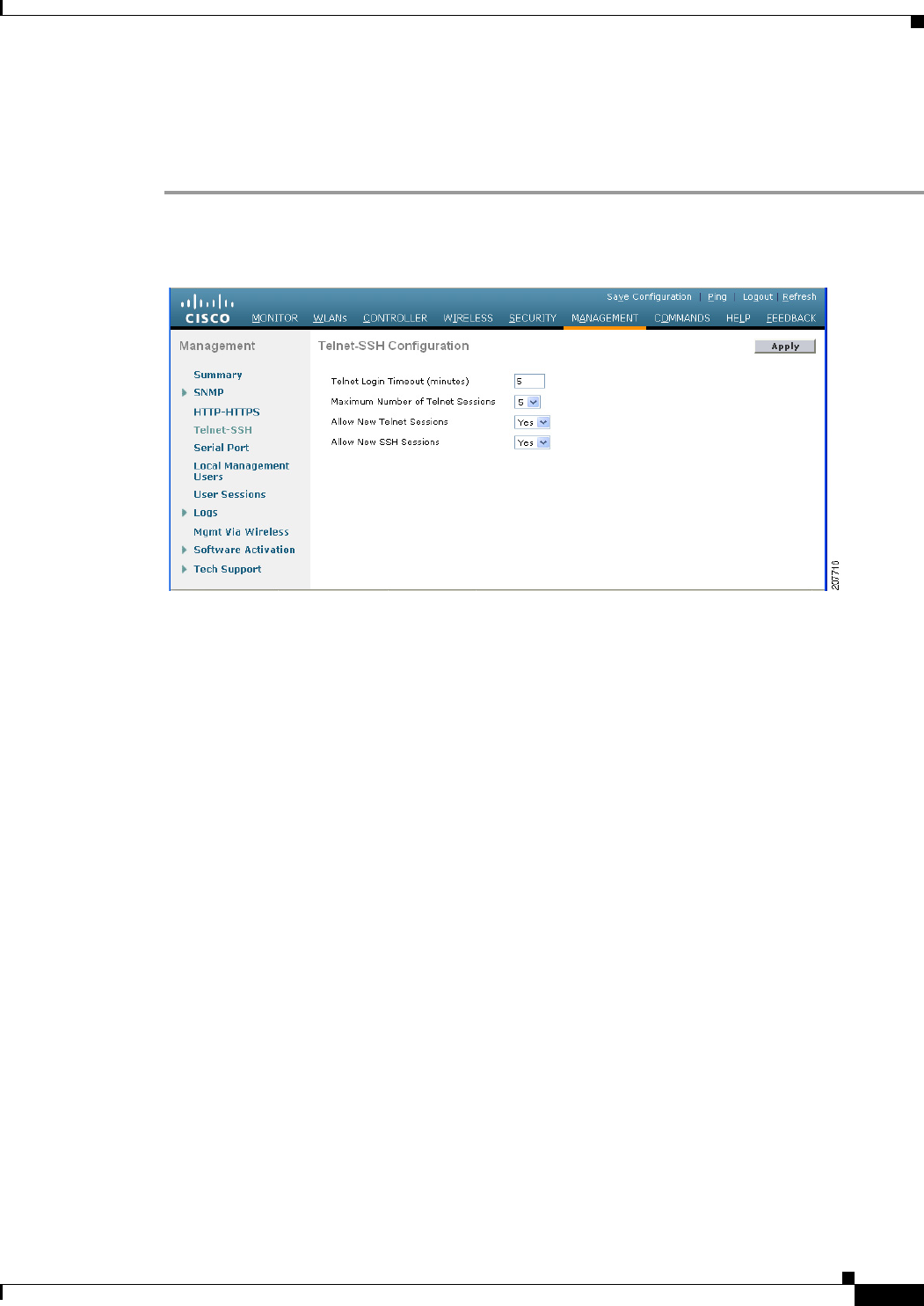
2-35
Cisco Wireless LAN Controller Configuration Guide
OL-21524-02
Chapter 2 Using the Web-Browser and CLI Interfaces
Configuring Telnet and SSH Sessions
Using the GUI to Configure Telnet and SSH Sessions
To configure Telnet and SSH using the controller GUI, follow these steps:
Step 1 Choose Management > Telnet-SSH to open the Telnet-SSH Configuration page (see Figure 2-16).
Figure 2-16 Telnet-SSH Configuration Page
Step 2 In the Telnet Login Timeout text box, enter the number of minutes that a Telnet session is allowed to
remain inactive before being terminated. The valid range is 0 to 160 minutes (inclusive), and the default
value is 5 minutes. A value of 0 indicates no timeout.
Step 3 From the Maximum Number of Sessions drop-down list, choose the number of simultaneous Telnet or
SSH sessions allowed. The valid range is 0 to 5 sessions (inclusive), and the default value is 5 sessions.
A value of zero indicates that Telnet/SSH sessions are disallowed.
Step 4 From the Allow New Telnet Sessions drop-down list, choose Ye s or No to allow or disallow new Telnet
sessions on the controller. The default value is No.
Step 5 From the Allow New SSH Sessions drop-down list, choose Ye s or No to allow or disallow new SSH
sessions on the controller. The default value is Yes.
Step 6 Click Apply to commit your changes.
Step 7 Click Save Configuration to save your changes.
Step 8 To see a summary of the Telnet configuration settings, choose Management > Summary. The Summary
page appears (see Figure 2-17).
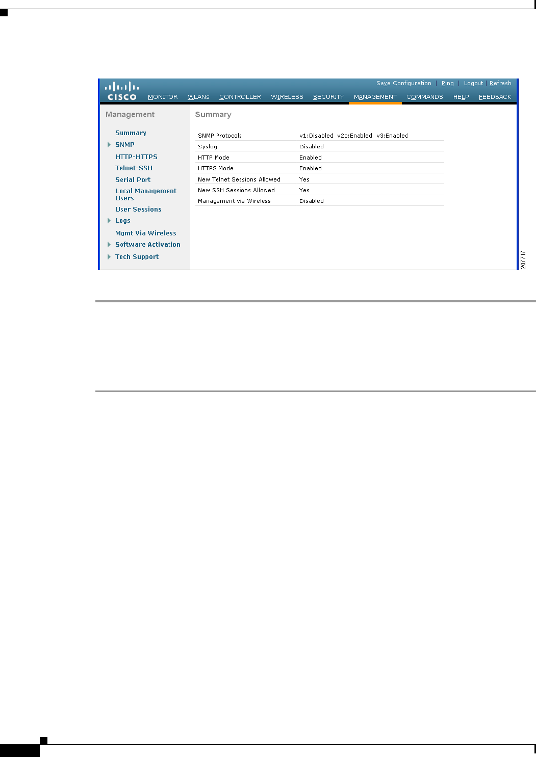
2-36
Cisco Wireless LAN Controller Configuration Guide
OL-21524-02
Chapter 2 Using the Web-Browser and CLI Interfaces
Configuring Telnet and SSH Sessions
Figure 2-17 Summary Page
This page shows whether additional Telnet and SSH sessions are permitted.
Using the CLI to Configure Telnet and SSH Sessions
To configure Telnet and SSH sessions using the controller CLI, follow these steps:
Step 1 To allow or disallow new Telnet sessions on the controller, enter this command:
config network telnet {enable | disable}
The default value is disabled.
Step 2 To allow or disallow new SSH sessions on the controller, enter this command:
config network ssh {enable | disable}
The default value is enabled.
Step 3 To specify the number of minutes that a Telnet session is allowed to remain inactive before being
terminated, enter this command:
config sessions timeout timeout
where timeout is a value between 0 and 160 minutes (inclusive). The default value is 5 minutes. A value
of 0 indicates no timeout.
Step 4 To specify the number of simultaneous Telnet or SSH sessions allowed, enter this command:
config sessions maxsessions session_num
where session_num is a value between 0 and 5 (inclusive). The default value is 5 sessions. A value of
zero indicates that Telnet/SSH sessions are disallowed.
Step 5 To save your changes, enter this command:
save config
Step 6 To see the Telnet and SSH configuration settings, enter this command:
show network summary

2-37
Cisco Wireless LAN Controller Configuration Guide
OL-21524-02
Chapter 2 Using the Web-Browser and CLI Interfaces
Enabling Wireless Connections to the GUI and CLI
Information similar to the following appears:
RF-Network Name............................. TestNetwork1
Web Mode.................................... Enable
Secure Web Mode............................. Enable
Secure Web Mode Cipher-Option High.......... Disable
Secure Web Mode Cipher-Option SSLv2......... Enable
Secure Shell (ssh).......................... Enable
Telnet................................... Disable
...
Step 7 To see the Telnet session configuration settings, enter this command:
show sessions
Information similar to the following appears:
CLI Login Timeout (minutes)............ 5
Maximum Number of CLI Sessions....... 5
Step 8 To see all active Telnet sessions, enter this command:
show loginsession
Information similar to the following appears:
ID User Name Connection From Idle Time Session Time
-- --------------- --------------- ------------ ------------
00 admin EIA-232 00:00:00 00:19:04
Step 9 If you ever want to close all active Telnet sessions or a specific Telnet session, enter this command:
config loginsession close {all | session_id}
Enabling Wireless Connections to the GUI and CLI
You can monitor and configure controllers using a wireless client. This feature is supported for all
management tasks except uploads from and downloads to the controller.
Before you can open the GUI or the CLI from a wireless client device, you must configure the controller
to allow the connection.
To enable wireless connections to the GUI or CLI, follow these steps:
Step 1 Log into the CLI.
Step 2 Enter config network mgmt-via-wireless enable.
Step 3 Use a wireless client to associate to a lightweight access point connected to the controller.
Step 4 On the wireless client, open a Telnet session to the controller, or browse to the controller GUI.
Tip To use the controller GUI to enable wireless connections, choose Management > Mgmt Via Wireless
page and select the Enable Controller Management to be accessible from Wireless Clients check
box.

2-38
Cisco Wireless LAN Controller Configuration Guide
OL-21524-02
Chapter 2 Using the Web-Browser and CLI Interfaces
Enabling Wireless Connections to the GUI and CLI

CHAPTER
3-1
Cisco Wireless LAN Controller Configuration Guide
OL-21524-02
3
Configuring Ports and Interfaces
This chapter describes the controller’s physical ports and interfaces and provides instructions for
configuring them. It contains these sections:
• Overview of Ports and Interfaces, page 3-1
• Configuring the Management, AP-Manager, Virtual, and Service-Port Interfaces, page 3-11
• Configuring Dynamic Interfaces, page 3-18
• Configuring Ports, page 3-23
• Choosing Between Link Aggregation and Multiple AP-Manager Interfaces, page 3-36
• Enabling Link Aggregation, page 3-36
• Configuring Multiple AP-Manager Interfaces, page 3-42
• Configuring VLAN Select, page 3-49
Overview of Ports and Interfaces
Three concepts are key to understanding how controllers connect to a wireless network: ports, interfaces,
and WLANs.
Ports
A port is a physical entity that is used for connections on the controller platform. Controllers have two
types of ports: distribution system ports and a service port. Figure 3-1 through Figure 3-4 show the ports
available on each controller.
Note The controller in a Cisco Integrated Services Router and the controllers on the Cisco WiSM do not have
external physical ports. They connect to the network through ports on the router or switch.
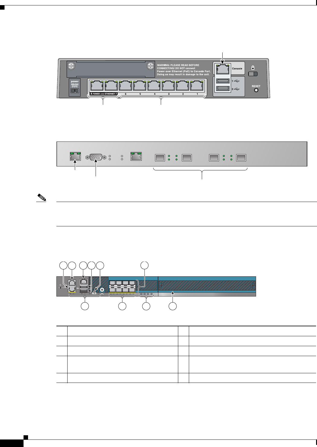
3-2
Cisco Wireless LAN Controller Configuration Guide
OL-21524-02
Chapter 3 Configuring Ports and Interfaces
Overview of Ports and Interfaces
Figure 3-1 Ports on the Cisco 2100 Series Wireless LAN Controllers
Figure 3-2 Ports on the Cisco 4400 Series Wireless LAN Controllers
Note Figure 3-2 shows a Cisco 4404 Controller. The Cisco 4402 Controller is similar but has only two
distribution system ports. The utility port, which is the unlabeled port in Figure 3-2, is currently not
operational.
Figure 3-3 Ports on the Cisco 5500 Series Wireless LAN Controllers
230622
Console port
Distribution system
ports 1-6
PoE-enabled
ports 7 and 8
146999
STATUS
ALARM
LINK
SERVICE CONSOLE
LINK ACT LINK ACT
UTILITY 1
PS1
PS2 ACT
LINK
ACT
2 3 4
Distribution system
ports 1-4
Service
port Serial
console port
1Redundant port for future use (RJ-45) 6SFP distribution system ports 1–8
2Service port (RJ-45) 7Management port LEDs
3Console port (RJ-45)1
1. You can use only one console port (either RJ-45 or mini USB). When you connect to one console port, the other is disabled.
8SFP distribution port Link and Activity LEDs
4
USB ports 0 and 1 (Type A) 9
Power supply (PS1 and PS2), System (SYS), and
Alarm (ALM) LEDs
5Console port (Mini USB Type B)110 Expansion module slot
251197
RP SP USB0 USB1 EN EN 12 34 56 78 PS1 PS2 SYS ALM
Cisco 5500 Series Wireless Controller
Model 5508
2
10
15
4
3
79
8
6

3-3
Cisco Wireless LAN Controller Configuration Guide
OL-21524-02
Chapter 3 Configuring Ports and Interfaces
Overview of Ports and Interfaces
Figure 3-4 Ports on the Catalyst 3750G Integrated Wireless LAN Controller Switch
Table 3-1 provides a list of ports per controller.
Note Appendix E provides logical connectivity diagrams and related software commands for the integrated
controllers.
Distribution System Ports
A distribution system port connects the controller to a neighbor switch and serves as the data path
between these two devices.
• Cisco 2100 Series Controllers have eight 10/100 copper Ethernet distribution system ports through
which the controller can support up to 6, 12, or 25 access points. Two of these ports (7 and 8) are
power-over-Ethernet (PoE) enabled and can be used to provide power directly to access points that
are connected to these ports.
155755
Controller console
port
Service
port
STACK1 STACK2
SWITCH
CONSOLE
CONTROLLER
CONSOLE SERVICE
Ta b l e 3-1 Controller Ports
Controller Service Ports
Distribution System
Ethernet Ports Serial Console Port
2100 series None 8 (6 + 2 PoE ports) 1
4402 121
4404 141
5508 18 (ports 1–8) 1
Cisco WiSM 2 (ports 9 and 10) 8 (ports 1–8) 2
Controller Network Module
within the Cisco 28/37/38xx
Series Integrated Services
Routers
None 1 11
Catalyst 3750G Integrated
Wireless LAN Controller Switch
12 (ports 27 and 28) 1
1. The baud rate for the Gigabit Ethernet version of the controller network module is limited to 9600 bps while the baud rate for
the Fast Ethernet version supports up to 57600 bps.

3-4
Cisco Wireless LAN Controller Configuration Guide
OL-21524-02
Chapter 3 Configuring Ports and Interfaces
Overview of Ports and Interfaces
Note All client connections to the Cisco 2100 Series Controller are limited to the 10/100 Ethernet
uplink port connection between the switch and the controller, even though their connection
speeds might be higher. The exception is for access points running in local hybrid-REAP
mode because this traffic is switched at the access point level and not forwarded back to the
controller.
• Cisco 4402 Controllers have two Gigabit Ethernet distribution system ports, each of which is
capable of managing up to 48 access points. However, we recommend no more than 25 access points
per port due to bandwidth constraints. The 4402-25 and 4402-50 models allow a total of 25 or 50
access points to join the controller.
• Cisco 4404 Controllers have four Gigabit Ethernet distribution system ports, each of which is
capable of managing up to 48 access points. However, we recommend no more than 25 access points
per port due to bandwidth constraints. The 4404-25, 4404-50, and 4404-100 models allow a total of
25, 50, or 100 access points to join the controller.
Note The Gigabit Ethernet ports on the Cisco 4402 and 4404 Controllers accept these SX/LC/T
small form-factor plug-in (SFP) modules:
- 1000BASE-SX SFP modules, which provide a 1000-Mbps wired connection to a network
through an 850nM (SX) fiber-optic link using an LC physical connector
- 1000BASE-LX SFP modules, which provide a 1000-Mbps wired connection to a network
through a 1300nM (LX/LH) fiber-optic link using an LC physical connector
- 1000BASE-T SFP modules, which provide a 1000-Mbps wired connection to a network
through a copper link using an RJ-45 physical connector
• Cisco 5508 Controllers have eight Gigabit Ethernet distribution system ports, through which the
Controller can manage multiple access points. The 5508-12, 5508-25, 5508-50, 5508-100, and
5508-250 models allow a total of 12, 25, 50, 100, or 250 access points to join the controller. Cisco
5508 controllers have no restrictions on the number of access points per port. However, we
recommend using link aggregation (LAG) or configuring dynamic AP-manager interfaces on each
Gigabit Ethernet port to automatically balance the load. If more than 100 access points are
connected to the Cisco 5500 Series Controller, make sure that more than one Gigabit Ethernet
interface is connected to the upstream switch.
Note The Gigabit Ethernet ports on the Cisco 5508 Controllers accept these SX/LC/T small
form-factor plug-in (SFP) modules:
- 1000BASE-SX SFP modules, which provide a 1000-Mbps wired connection to a network
through an 850nM (SX) fiber-optic link using an LC physical connector
- 1000BASE-LX SFP modules, which provide a 1000-Mbps wired connection to a network
through a 1300nM (LX/LH) fiber-optic link using an LC physical connector
- 1000BASE-T SFP modules, which provide a 1000-Mbps wired connection to a network
through a copper link using an RJ-45 physical connector
• The Catalyst 6500 series switch Wireless Services Module (WiSM) and the Cisco 7600 series router
Wireless Services Module (WiSM) have eight internal Gigabit Ethernet distribution system ports
(ports 1 through 8) that connect the switch or router and the integrated controller. These internal
ports are located on the backplane of the switch or router and are not visible on the front panel.
Through these ports, the controller can support up to 300 access points.

3-5
Cisco Wireless LAN Controller Configuration Guide
OL-21524-02
Chapter 3 Configuring Ports and Interfaces
Overview of Ports and Interfaces
• The controller network module within the Cisco 28/37/38xx Series Integrated Services Router can
support up to 6, 8, 12, or 25 access points (and up to 256, 256, 350, or 350 clients, respectively),
depending on the version of the network module. The network module supports these access points
through a Fast Ethernet distribution system port (on the NM-AIR-WLC6-K9 6-access-point version)
or a Gigabit Ethernet distribution system port (on the 8-, 12-, and 25-access-point versions and on
the NME-AIR-WLC6-K9 6-access-point version) that connects the router and the integrated
controller. This port is located on the router backplane and is not visible on the front panel. The Fast
Ethernet port operates at speeds up to 100 Mbps, and the Gigabit Ethernet port operates at speeds
up to 1 Gbps.
• The Catalyst 3750G Integrated Wireless LAN Controller Switch has two internal Gigabit Ethernet
distribution system ports (ports 27 and 28) that connect the switch and the integrated controller.
These internal ports are located on the switch backplane and are not visible on the front panel. Each
port is capable of managing up to 48 access points. However, we recommend no more than 25 access
points per port due to bandwidth constraints. The -S25 and -S50 models allow a total of 25 or 50
access points to join the controller.
Note See the “Choosing Between Link Aggregation and Multiple AP-Manager Interfaces” section on
page 3-36 if you want to configure your Cisco 4400 Series Controller to support more than 48 access
points.
Each distribution system port is, by default, an 802.1Q VLAN trunk port. The VLAN trunking
characteristics of the port are not configurable.
Note Some controllers support link aggregation (LAG), which bundles all of the controller’s distribution
system ports into a single 802.3ad port channel. Cisco 4400 Series Controllers support LAG in software
release 3.2 or later releases, Cisco 5500 Series Controllers support LAG in software release 6.0 or later
releases, and LAG is enabled automatically on the controllers within the Cisco WiSM and the Catalyst
3750G Integrated Wireless LAN Controller Switch. See the “Enabling Link Aggregation” section on
page 3-36 for more information.
Service Port
Cisco 4400 and Cisco 5500 Series Controllers also have a 10/100 copper Ethernet service port. The
service port is controlled by the service-port interface and is reserved for out-of-band management of
the controller and system recovery and maintenance in the event of a network failure. It is also the only
port that is active when the controller is in boot mode. The service port is not capable of carrying 802.1Q
tags, so it must be connected to an access port on the neighbor switch. Use of the service port is optional.
Note The Cisco WiSM’s controllers use the service port for internal protocol communication between the
controllers and the Supervisor 720.
Note The Cisco 2100 Series Controller and the controller in the Cisco Integrated Services Router do not have
a service port.

3-6
Cisco Wireless LAN Controller Configuration Guide
OL-21524-02
Chapter 3 Configuring Ports and Interfaces
Overview of Ports and Interfaces
Note The service port is not autosensing. You must use the correct straight-through or crossover Ethernet
cable to communicate with the service port.
Caution Do not configure wired clients in the same VLAN or subnet of the service port on the network. If you
configure wired clients on the same subnet or VLAN as the service port, you will not be able to access
the management interface.
Interfaces
An interface is a logical entity on the controller. An interface has multiple parameters associated with it,
including an IP address, default gateway (for the IP subnet), primary physical port, secondary physical
port, VLAN identifier, and DHCP server.
These five types of interfaces are available on the controller. Four of these are static and are configured
at setup time:
• Management interface (static and configured at setup time; mandatory)
• AP-manager interface (static and configured at setup time; mandatory)
Note You are not required to configure an AP-manager interface on Cisco 5500 Series
Controllers.
• Virtual interface (static and configured at setup time; mandatory)
• Service-port interface (static and configured at setup time; optional)
• Dynamic interface (user-defined)
Each interface is mapped to at least one primary port, and some interfaces (management and dynamic)
can be mapped to an optional secondary (or backup) port. If the primary port for an interface fails, the
interface automatically moves to the backup port. In addition, multiple interfaces can be mapped to a
single controller port.
Note For Cisco 5500 Series Controllers in a non-link-aggregation (non-LAG) configuration, the management
interface must be on a different VLAN than any dynamic AP-manager interface. Otherwise, the
management interface cannot fail over to the port that the AP-manager is on.
Note Cisco 5500 Series Controllers do not support fragmented pings on any interface. Similarly, Cisco 4400
Series Controllers, the Cisco WiSM, and the Catalyst 3750G Integrated Wireless LAN Controller Switch
do not support fragmented pings on the AP-manager interface.
Note See the “Enabling Link Aggregation” section on page 3-36 if you want to configure the controller to
dynamically map the interfaces to a single port channel rather than having to configure primary and
secondary ports for each interface.

3-7
Cisco Wireless LAN Controller Configuration Guide
OL-21524-02
Chapter 3 Configuring Ports and Interfaces
Overview of Ports and Interfaces
Management Interface
The management interface is the default interface for in-band management of the controller and
connectivity to enterprise services such as AAA servers. It is also used for communications between the
controller and access points. The management interface has the only consistently “pingable” in-band
interface IP address on the controller. You can access the controller’s GUI by entering the controller’s
management interface IP address in Internet Explorer’s or Mozilla Firefox’s address field.
For CAPWAP, the controller requires one management interface to control all inter-controller
communications and one AP-manager interface to control all controller-to-access point
communications, regardless of the number of ports.
Note If the service port is in use, the management interface must be on a different supernet from the
service-port interface.
Caution Do not map a guest WLAN to the management interface. If the EoIP tunnel breaks, the client could
obtain an IP and be placed on the management subnet.
Caution Do not configure wired clients in the same VLAN or subnet of the service port on the network. If you
configure wired clients on the same subnet or VLAN as the service port, you will not be able to access
the management interface.
AP-Manager Interface
A controller has one or more AP-manager interfaces, which are used for all Layer 3 communications
between the controller and lightweight access points after the access points have joined the controller.
The AP-manager IP address is used as the tunnel source for CAPWAP packets from the controller to the
access point and as the destination for CAPWAP packets from the access point to the controller.
Note For Cisco 5500 Series Controllers, you are not required to configure an AP-manager interface. The
management interface acts like an AP-manager interface by default, and the access points can join on
this interface.
Note The Controller does not support transmitting the jumbo frames. To avoid having the controller transmit
CAPWAP packets to the AP that will necessitate fragmentation and reassembly, reduce MTU/MSS on
the client side.
Note With the 7.0.116.0 release onwards, the MAC address of the management interface and the AP-manager
interface is the same as the base LAG MAC address.
The AP-manager interface communicates through any distribution system port by listening across the
Layer 3 network for access point CAPWAP or LWAPP join messages to associate and communicate with
as many lightweight access points as possible.

3-8
Cisco Wireless LAN Controller Configuration Guide
OL-21524-02
Chapter 3 Configuring Ports and Interfaces
Overview of Ports and Interfaces
For Cisco 4404 and WiSM Controllers, configure the AP-manager interface on all distribution system
ports (1, 2, 3, and 4). For Cisco 4402 Controllers, configure the AP-manager interface on distribution
system ports 1 and 2. In both cases, the static (or permanent) AP-manager interface is always assigned
to distribution system port 1 and given a unique IP address. Configuring the AP-manager interface on
the same VLAN or IP subnet as the management interface results in optimum access point association.
Note If only one distribution system port can be used, you should use distribution system port 1.
If link aggregation (LAG) is enabled, there can be only one AP-manager interface. But when LAG is
disabled, one or more AP-manager interfaces can be created, generally one per physical port.
Note The Cisco 2100 Series Controllers do not support LAG.
Note Port redundancy for the AP-manager interface is not supported. You cannot map the AP-manager
interface to a backup port.
Note See the “Configuring Multiple AP-Manager Interfaces” section on page 3-42 for information on creating
and using multiple AP-manager interfaces.
Virtual Interface
The virtual interface is used to support mobility management, Dynamic Host Configuration Protocol
(DHCP) relay, and embedded Layer 3 security such as guest web authentication and VPN termination.
It also maintains the DNS gateway host name used by Layer 3 security and mobility managers to verify
the source of certificates when Layer 3 web authorization is enabled.
Specifically, the virtual interface plays these two primary roles:
• Acts as the DHCP server placeholder for wireless clients that obtain their IP address from a DHCP
server.
• Serves as the redirect address for the web authentication login page.
Note See Chapter 6, “Configuring Security Solutions,” for additional information on web
authentication.
The virtual interface IP address is used only in communications between the controller and wireless
clients. It never appears as the source or destination address of a packet that goes out a distribution
system port and onto the switched network. For the system to operate correctly, the virtual interface IP
address must be set (it cannot be 0.0.0.0), and no other device on the network can have the same address
as the virtual interface. Therefore, the virtual interface must be configured with an unassigned and
unused gateway IP address. The virtual interface IP address is not pingable and should not exist in any
routing table in your network. In addition, the virtual interface cannot be mapped to a backup port.

3-9
Cisco Wireless LAN Controller Configuration Guide
OL-21524-02
Chapter 3 Configuring Ports and Interfaces
Overview of Ports and Interfaces
Note All controllers within a mobility group must be configured with the same virtual interface IP address.
Otherwise, inter-controller roaming may appear to work, but the handoff does not complete, and the
client loses connectivity for a period of time.
Service-Port Interface
The service-port interface controls communications through and is statically mapped by the system to
the service port. The service port can obtain an IP address using DHCP, or it can be assigned a static IP
address, but a default gateway cannot be assigned to the service-port interface. Static routes can be
defined through the controller for remote network access to the service port.
Note Only Cisco 4400 and Cisco 5500 Series Controllers have a service-port interface.
Note You must configure an IP address on the service-port interface of both Cisco WiSM controllers.
Otherwise, the neighbor switch is unable to check the status of each controller.
Dynamic Interface
Dynamic interfaces, also known as VLAN interfaces, are created by users and designed to be analogous
to VLANs for wireless LAN clients. A controller can support up to 512 dynamic interfaces (VLANs).
Each dynamic interface is individually configured and allows separate communication streams to exist
on any or all of a controller’s distribution system ports. Each dynamic interface controls VLANs and
other communications between controllers and all other network devices, and each acts as a DHCP relay
for wireless clients associated to WLANs mapped to the interface. You can assign dynamic interfaces to
distribution system ports, WLANs, the Layer 2 management interface, and the Layer 3 AP-manager
interface, and you can map the dynamic interface to a backup port.
You can configure zero, one, or multiple dynamic interfaces on a distribution system port. However, all
dynamic interfaces must be on a different VLAN or IP subnet from all other interfaces configured on the
port. If the port is untagged, all dynamic interfaces must be on a different IP subnet from any other
interface configured on the port.
Note A controller’s WLAN dynamic interface and all wireless clients in the WLAN that are local to the
controller must have IP addresses in the same subnet.
Note We recommend using tagged VLANs for dynamic interfaces.
Dynamic AP Management
A dynamic interface is created as a WLAN interface by default. However, any dynamic interface can be
configured as an AP-manager interface, with one AP-manager interface allowed per physical port. A
dynamic interface with the Dynamic AP Management option enabled is used as the tunnel source for
packets from the controller to the access point and as the destination for CAPWAP packets from the
access point to the controller. The dynamic interfaces for AP management must have a unique IP address
and are usually configured on the same subnet as the management interface.
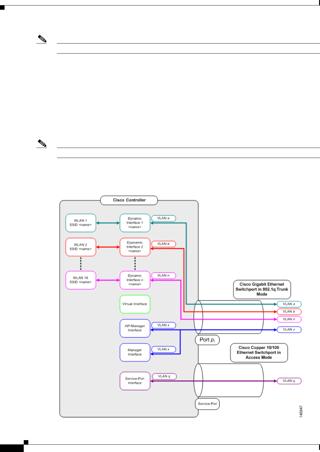
3-10
Cisco Wireless LAN Controller Configuration Guide
OL-21524-02
Chapter 3 Configuring Ports and Interfaces
Overview of Ports and Interfaces
Note If link aggregation (LAG) is enabled, there can be only one AP-manager interface.
We recommend having a separate dynamic AP-manager interface per controller port. See the
“Configuring Multiple AP-Manager Interfaces” section on page 3-42 for instructions on configuring
multiple dynamic AP-manager interfaces.
WLANs
A WLAN associates a service set identifier (SSID) to an interface. It is configured with security, quality
of service (QoS), radio policies, and other wireless network parameters. Up to 512 access point WLANs
can be configured per controller.
Note Chapter 7, “Configuring WLANs,” provides instructions for configuring WLANs.
Figure 3-5 shows the relationship between ports, interfaces, and WLANs.
Figure 3-5 Ports, Interfaces, and WLANs

3-11
Cisco Wireless LAN Controller Configuration Guide
OL-21524-02
Chapter 3 Configuring Ports and Interfaces
Configuring the Management, AP-Manager, Virtual, and Service-Port Interfaces
As shown in Figure 3-5, each controller port connection is an 802.1Q trunk and should be configured as
such on the neighbor switch. On Cisco switches, the native VLAN of an 802.1Q trunk is an untagged
VLAN. If you configure an interface to use the native VLAN on a neighboring Cisco switch, make sure
you configure the interface on the controller to be untagged.
Note A zero value for the VLAN identifier (on the Controller > Interfaces page) means that the interface is
untagged.
The default (untagged) native VLAN on Cisco switches is VLAN 1. When controller interfaces are
configured as tagged (meaning that the VLAN identifier is set to a nonzero value), the VLAN must be
allowed on the 802.1Q trunk configuration on the neighbor switch and not be the native untagged VLAN.
We recommend that tagged VLANs be used on the controller. You should also allow only relevant
VLANs on the neighbor switch’s 802.1Q trunk connections to controller ports. All other VLANs should
be disallowed or pruned in the switch port trunk configuration. This practice is extremely important for
optimal performance of the controller.
Note We recommend that you assign one set of VLANs for WLANs and a different set of VLANs for
management interfaces to ensure that controllers properly route VLAN traffic.
Configuring the Management, AP-Manager, Virtual, and
Service-Port Interfaces
Typically, you define the management, AP-manager, virtual, and service-port interface parameters using
the Startup Wizard. However, you can display and configure interface parameters through either the GUI
or CLI after the controller is running.
Note When assigning a WLAN to a DHCP server, both should be on the same subnet. Otherwise, you need to
use a router to route traffic between the WLAN and the DHCP server.
Using the GUI to Configure the Management, AP-Manager, Virtual, and
Service-Port Interfaces
To display and configure the management, AP-manager, virtual, and service-port interface parameters
using the controller GUI, follow these steps:
Step 1 Choose Controller > Interfaces to open the Interfaces page (see Figure 3-6).

3-12
Cisco Wireless LAN Controller Configuration Guide
OL-21524-02
Chapter 3 Configuring Ports and Interfaces
Configuring the Management, AP-Manager, Virtual, and Service-Port Interfaces
Figure 3-6 Interfaces Page
This page shows the current controller interface settings.
Step 2 If you want to modify the settings of a particular interface, click the name of the interface. The Interfaces
> Edit page for that interface appears.
Step 3 Configure the following parameters for each interface type:
Management Interface
Note The management interface uses the controller’s factory-set distribution system MAC address.
• Quarantine and quarantine VLAN ID, if applicable
Note Select the Quarantine check box if you want to configure this VLAN as unhealthy or you
want to configure network access control (NAC) out-of-band integration. Doing so causes
the data traffic of any client that is assigned to this VLAN to pass through the controller. See
Chapter 7, “Configuring WLANs,” for more information about NAC out-of-band
integration.
• NAT address (only for Cisco 5500 Series Controllers configured for dynamic AP management)
Note Select the Enable NAT Address check box and enter the external NAT IP address if you
want to be able to deploy your Cisco 5500 Series Controller behind a router or other gateway
device that is using one-to-one mapping network address translation (NAT). NAT allows a
device, such as a router, to act as an agent between the Internet (public) and a local network
(private). In this case, it maps the controller’s intranet IP addresses to a corresponding
external address. The controller’s dynamic AP-manager interface must be configured with
the external NAT IP address so that the controller can send the correct IP address in the
Discovery Response.
Note The NAT parameters are supported for use only with one-to-one-mapping NAT, where each
private client has a direct and fixed mapping to a global address. The NAT parameters do not
support one-to-many NAT, which uses source port mapping to enable a group of clients to
be represented by a single IP address.

3-13
Cisco Wireless LAN Controller Configuration Guide
OL-21524-02
Chapter 3 Configuring Ports and Interfaces
Configuring the Management, AP-Manager, Virtual, and Service-Port Interfaces
Note If a Cisco 5500 Series Controller is configured with an external NAT IP address under the
management interface, the APs in local mode cannot associate with the controller. The
workaround is to either ensure that the management interface has a globally valid IP address
or ensure that external NAT IP address is valid internally for the local APs.
• VLAN identifier
Note Enter 0 for an untagged VLAN or a nonzero value for a tagged VLAN. We recommend using
tagged VLANs for the management interface.
• Fixed IP address, IP netmask, and default gateway
• Dynamic AP management (for Cisco 5500 Series Controllers only)
Note For Cisco 5500 Series Controllers, the management interface acts like an AP-manager
interface by default. If desired, you can disable the management interface as an AP-manager
interface and create another dynamic interface as an AP manager.
• Physical port assignment (for all controllers except the Cisco 5500 Series Controller)
• Primary and secondary DHCP servers
• Access control list (ACL) setting, if required
Note To create ACLs, follow the instructions in Chapter 6, “Configuring Security Solutions.”
AP-Manager Interface
Note For Cisco 5500 Series Controllers, you are not required to configure an AP-manager interface.
The management interface acts like an AP-manager interface by default.
• Physical port assignment
• VLAN identifier
Note Enter 0 for an untagged VLAN or a nonzero value for a tagged VLAN. We recommend using
tagged VLANs for the AP-manager interface.
• Fixed IP address, IP netmask, and default gateway
Note The AP-manager interface’s IP address must be different from the management interface’s
IP address and may or may not be on the same subnet as the management interface. However,
we recommend that both interfaces be on the same subnet for optimum access point
association.
• Primary and secondary DHCP servers
• Access control list (ACL) name, if required

3-14
Cisco Wireless LAN Controller Configuration Guide
OL-21524-02
Chapter 3 Configuring Ports and Interfaces
Configuring the Management, AP-Manager, Virtual, and Service-Port Interfaces
Note To create ACLs, follow the instructions in Chapter 6, “Configuring Security Solutions.”
Virtual Interface
• Any fictitious, unassigned, and unused gateway IP address
• DNS gateway hostname
Note To ensure connectivity and web authentication, the DNS server should always point to the
virtual interface. If a DNS hostname is configured for the virtual interface, then the same
DNS host name must be configured on the DNS server(s) used by the client.
Service-Port Interface
Note The service-port interface uses the controller’s factory-set service-port MAC address.
• DHCP protocol (enabled)
• DHCP protocol (disabled) and IP address and IP netmask
Step 4 Click Save Configuration to save your changes.
Step 5 If you made any changes to the management or virtual interface, reboot the controller so that your
changes take effect.
Using the CLI to Configure the Management, AP-Manager, Virtual, and
Service-Port Interfaces
This section provides instructions for displaying and configuring the management, AP-manager, virtual,
and service-port interfaces using the CLI.
Using the CLI to Configure the Management Interface
To display and configure the management interface parameters using the CLI, follow these steps:
Step 1 Enter the show interface detailed management command to view the current management interface
settings.
Note The management interface uses the controller’s factory-set distribution system MAC address.
Step 2 Enter the config wlan disable wlan-number command to disable each WLAN that uses the management
interface for distribution system communication.
Step 3 Enter these commands to define the management interface:
• config interface address management ip-addr ip-netmask gateway
• config interface quarantine vlan management vlan_id

3-15
Cisco Wireless LAN Controller Configuration Guide
OL-21524-02
Chapter 3 Configuring Ports and Interfaces
Configuring the Management, AP-Manager, Virtual, and Service-Port Interfaces
Note Use the config interface quarantine vlan management vlan_id command to configure a
quarantine VLAN on the management interface.
• config interface vlan management {vlan-id | 0}
Note Enter 0 for an untagged VLAN or a nonzero value for a tagged VLAN. We recommend using
tagged VLANs for the management interface.
• config interface ap-manager management {enable | disable} (for Cisco 5500 Series Controllers
only)
Note Use the config interface ap-manager management {enable | disable} command to enable
or disable dynamic AP management for the management interface. For Cisco 5500 Series
Controllers, the management interface acts like an AP-manager interface by default. If
desired, you can disable the management interface as an AP-manager interface and create
another dynamic interface as an AP manager.
• config interface port management physical-ds-port-number (for all controllers except the 5500
series)
• config interface dhcp management ip-address-of-primary-dhcp-server
[ip-address-of-secondary-dhcp-server]
• config interface acl management access-control-list-name
Note See Chapter 6, “Configuring Security Solutions,” for more information on ACLs.
Step 4 Enter these commands if you want to be able to deploy your Cisco 5500 Series Controller behind a router
or other gateway device that is using one-to-one mapping network address translation (NAT):
• config interface nat-address management {enable | disable}
• config interface nat-address management set public_IP_address
NAT allows a device, such as a router, to act as an agent between the Internet (public) and a local network
(private). In this case, it maps the controller’s intranet IP addresses to a corresponding external address.
The controller’s dynamic AP-manager interface must be configured with the external NAT IP address so
that the controller can send the correct IP address in the Discovery Response.
Note These NAT commands can be used only on Cisco 5500 Series Controllers and only if the
management interface is configured for dynamic AP management.
Note These commands are supported for use only with one-to-one-mapping NAT, where each private
client has a direct and fixed mapping to a global address. These commands do not support
one-to-many NAT, which uses source port mapping to enable a group of clients to be represented
by a single IP address.
Step 5 Enter the save config command to save your changes.

3-16
Cisco Wireless LAN Controller Configuration Guide
OL-21524-02
Chapter 3 Configuring Ports and Interfaces
Configuring the Management, AP-Manager, Virtual, and Service-Port Interfaces
Step 6 Enter the show interface detailed management command to verify that your changes have been saved.
Step 7 If you made any changes to the management interface, enter the reset system command to reboot the
controller in order for the changes to take effect.
Using the CLI to Configure the AP-Manager Interface
To display and configure the AP-manager interface parameters using the CLI, follow these steps:
Note For Cisco 5500 Series Controllers, you are not required to configure an AP-manager interface. The
management interface acts like an AP-manager interface by default.
Step 1 Enter the show interface summary command to view the current interfaces.
Note If the system is operating in Layer 2 mode, the AP-manager interface is not listed.
Step 2 Enter the show interface detailed ap-manager command to view the current AP-manager interface
settings.
Step 3 Enter the config wlan disable wlan-number command to disable each WLAN that uses the AP-manager
interface for distribution system communication.
Step 4 Enter these commands to define the AP-manager interface:
• config interface address ap-manager ip-addr ip-netmask gateway
• config interface vlan ap-manager {vlan-id | 0}
Note Enter 0 for an untagged VLAN or a nonzero value for a tagged VLAN. We recommend using
tagged VLANs for the AP-manager interface.
• config interface port ap-manager physical-ds-port-number
• config interface dhcp ap-manager ip-address-of-primary-dhcp-server
[ip-address-of-secondary-dhcp-server]
• config interface acl ap-manager access-control-list-name
Note See Chapter 6, “Configuring Security Solutions,” for more information on ACLs.
Step 5 Enter the save config command to save your changes.
Step 6 Enter the show interface detailed ap-manager command to verify that your changes have been saved.
Using the CLI to Configure the Virtual Interface
To display and configure the virtual interface parameters using the CLI, follow these steps:

3-17
Cisco Wireless LAN Controller Configuration Guide
OL-21524-02
Chapter 3 Configuring Ports and Interfaces
Configuring the Management, AP-Manager, Virtual, and Service-Port Interfaces
Step 1 Enter the show interface detailed virtual command to view the current virtual interface settings.
Step 2 Enter the config wlan disable wlan-number command to disable each WLAN that uses the virtual
interface for distribution system communication.
Step 3 Enter these commands to define the virtual interface:
• config interface address virtual ip-address
Note For ip-address, enter any fictitious, unassigned, and unused gateway IP address.
• config interface hostname virtual dns-host-name
Step 4 Enter the reset system command. At the confirmation prompt, enter Y to save your configuration
changes to NVRAM. The controller reboots.
Step 5 Enter the show interface detailed virtual command to verify that your changes have been saved.
Using the CLI to Configure the Service-Port Interface
To display and configure the service-port interface parameters using the CLI, follow these steps:
Step 1 Enter the show interface detailed service-port command to view the current service-port interface
settings.
Note The service-port interface uses the controller’s factory-set service-port MAC address.
Step 2 Enter these commands to define the service-port interface:
• To configure the DHCP server: config interface dhcp service-port ip-address-of-primary-dhcp-
server [ip-address-of-secondary-dhcp-server]
• To disable the DHCP server: config interface dhcp service-port none
• To configure the IP address: config interface address service-port ip-addr ip-netmask
Step 3 The service port is used for out-of-band management of the controller. If the management workstation
is in a remote subnet, you may need to add a route on the controller in order to manage the controller
from that remote workstation. To do so, enter this command:
config route add network-ip-addr ip-netmask gateway
Step 4 Enter the save config command to save your changes.
Step 5 Enter the show interface detailed service-port command to verify that your changes have been saved.
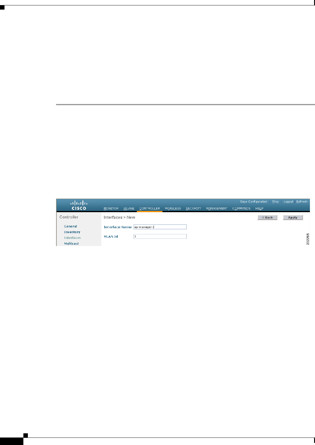
3-18
Cisco Wireless LAN Controller Configuration Guide
OL-21524-02
Chapter 3 Configuring Ports and Interfaces
Configuring Dynamic Interfaces
Configuring Dynamic Interfaces
This section provides instructions for configuring dynamic interfaces using either the GUI or CLI.
Using the GUI to Configure Dynamic Interfaces
To create new or edit existing dynamic interfaces using the controller GUI, follow these steps:
Step 1 Choose Controller > Interfaces to open the Interfaces page (see Figure 3-6).
Step 2 Perform one of the following:
• To create a new dynamic interface, click New. The Interfaces > New page appears (see Figure 3-7).
Go to Step 3.
• To modify the settings of an existing dynamic interface, click the name of the interface. The
Interfaces > Edit page for that interface appears (see Figure 3-8). Go to Step 5.
• To delete an existing dynamic interface, hover your cursor over the blue drop-down arrow for the
desired interface and choose Remove.
Figure 3-7 Interfaces > New Page
Step 3 Enter an interface name and a VLAN identifier, as shown in Figure 3-7.
Step 4 Click Apply to commit your changes. The Interfaces > Edit page appears (see Figure 3-8).
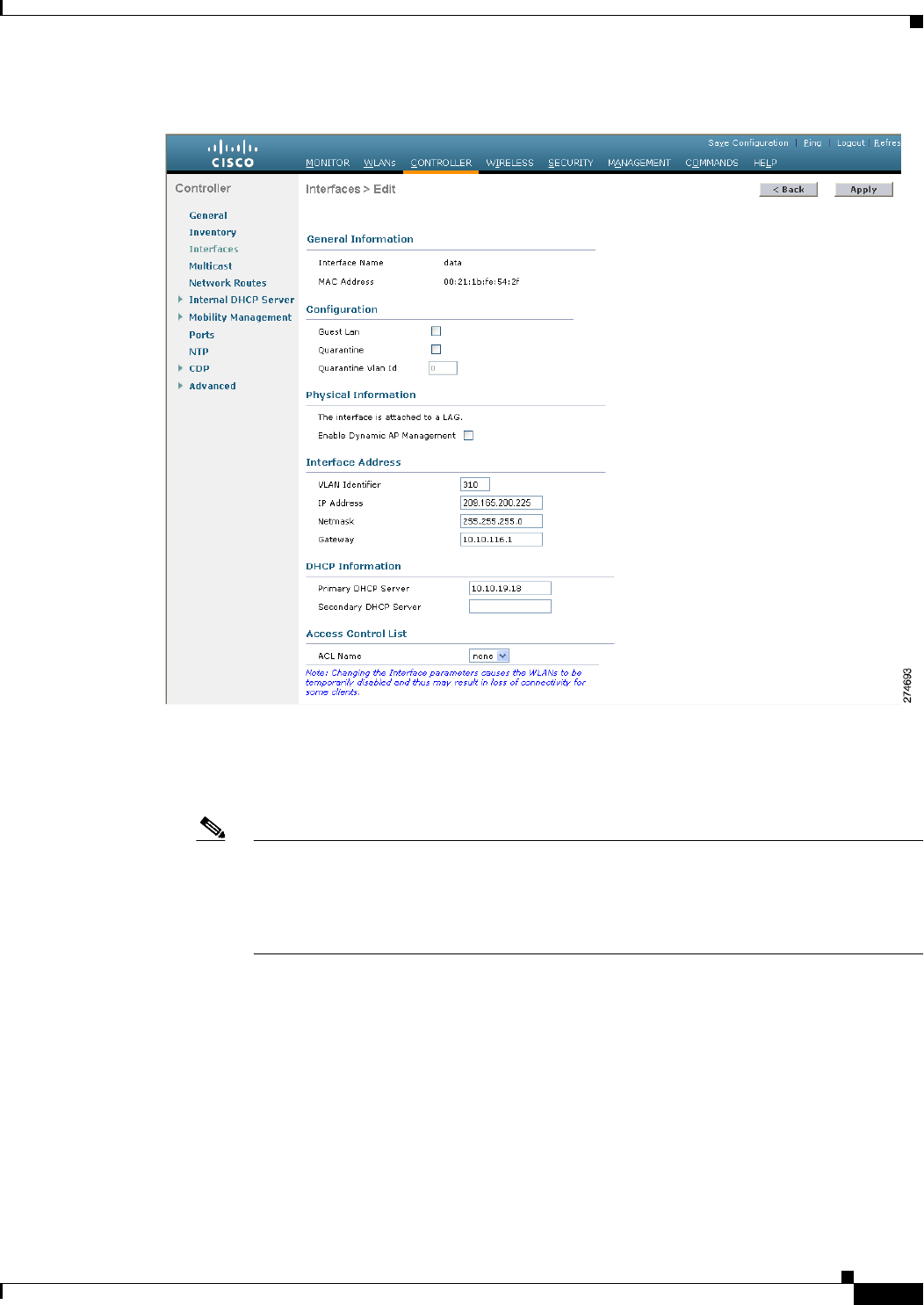
3-19
Cisco Wireless LAN Controller Configuration Guide
OL-21524-02
Chapter 3 Configuring Ports and Interfaces
Configuring Dynamic Interfaces
Figure 3-8 Interfaces > Edit Page
Step 5 Configure the following parameters:
• Guest LAN, if applicable
• Quarantine and quarantine VLAN ID, if applicable
Note Select the Quarantine check box if you want to configure this VLAN as unhealthy or you
want to configure network access control (NAC) out-of-band integration. Doing so causes
the data traffic of any client that is assigned to this VLAN to pass through the controller. See
Chapter 7, “Configuring WLANs,” for more information about NAC out-of-band
integration.
• Physical port assignment (for all controllers except the 5500 series)
• NAT address (only for Cisco 5500 Series Controllers configured for dynamic AP management)

3-20
Cisco Wireless LAN Controller Configuration Guide
OL-21524-02
Chapter 3 Configuring Ports and Interfaces
Configuring Dynamic Interfaces
Note Select the Enable NAT Address check box and enter the external NAT IP address if you
want to be able to deploy your Cisco 5500 Series Controller behind a router or other gateway
device that is using one-to-one mapping network address translation (NAT). NAT allows a
device, such as a router, to act as an agent between the Internet (public) and a local network
(private). In this case, it maps the controller’s intranet IP addresses to a corresponding
external address. The controller’s dynamic AP-manager interface must be configured with
the external NAT IP address so that the controller can send the correct IP address in the
Discovery Response.
Note The NAT parameters are supported for use only with one-to-one-mapping NAT, where each
private client has a direct and fixed mapping to a global address. The NAT parameters do not
support one-to-many NAT, which uses source port mapping to enable a group of clients to
be represented by a single IP address.
• Dynamic AP management
Note When you enable this feature, this dynamic interface is configured as an AP-manager
interface (only one AP-manager interface is allowed per physical port). A dynamic interface
that is marked as an AP-manager interface cannot be used as a WLAN interface.
Note Set the APs in a VLAN that is different than the dynamic interface configured on the
controller. If the APs are in the same VLAN as the dynamic interface, the APs are not
registered on the controller and the “LWAPP discovery rejected” and “Layer 3 discovery
request not received on management VLAN” errors are logged on the controller.
• VLAN identifier
• Fixed IP address, IP netmask, and default gateway
• Primary and secondary DHCP servers
• Access control list (ACL) name, if required
Note See Chapter 6, “Configuring Security Solutions,” for more information on ACLs.
Note To ensure proper operation, you must set the Port Number and Primary DHCP Server
parameters.
Step 6 Click Save Configuration to save your changes.
Step 7 Repeat this procedure for each dynamic interface that you want to create or edit.

3-21
Cisco Wireless LAN Controller Configuration Guide
OL-21524-02
Chapter 3 Configuring Ports and Interfaces
Configuring Dynamic Interfaces
Note When you apply a flow policer or an aggregate policer on the ingress of a Dynamic Interface VLAN for
the Upstream (wireless to wired) traffic, it is not possible to police because the vLAN based policy has
no effect and thus no policing occurs. When the traffic comes out of the WiSM LAG (L2) and hits the
Switch Virtual Interface (SVI) (L3), the QoS policy applied is a VLAN based policy that has no effect
on the policing.
To enable ingress L3 VLAN based policy on the SVI, you must enable VLAN based QoS equivalent to
mls qos vlan-based command on the WiSM LAG. All the previous 12.2(33)SXI releases, which support
Auto LAG for WiSM only, that is 12.2(33)SXI, 12.2(33)SXI1, 12.2(33)SXI2a, 12.2(33)SXI3, and so on,
do not have this WiSM CLI. Therefore, the VLAN based QoS policy applied ingress on the SVI for
wireless to wired traffic never polices any traffic coming out of the WiSM LAG and hitting the SVI. The
commands equivalent to the mls qos vlan-based command are as follows:
Standalone: wism module module_no controller controller_no qos-vlan-based
Virtual Switching System: wism switch switch_no module module_no controller controller_no
qos-vlan-based
Using the CLI to Configure Dynamic Interfaces
To configure dynamic interfaces using the CLI, follow these steps:
Step 1 Enter the show interface summary command to view the current dynamic interfaces.
Step 2 View the details of a specific dynamic interface by entering this command:
show interface detailed operator_defined_interface_name.
Step 3 Enter the config wlan disable wlan_id command to disable each WLAN that uses the dynamic interface
for distribution system communication.
Step 4 Enter these commands to configure dynamic interfaces:
• config interface create operator_defined_interface_name {vlan_id | x}
• config interface address operator_defined_interface_name ip_addr ip_netmask [gateway]
• config interface vlan operator_defined_interface_name {vlan_id | 0}
• config interface port operator_defined_interface_name physical_ds_port_number
• config interface ap-manager operator_defined_interface_name {enable | disable}
Note Use the config interface ap-manager operator_defined_interface_name {enable | disable}
command to enable or disable dynamic AP management. When you enable this feature, this
dynamic interface is configured as an AP-manager interface (only one AP-manager interface
is allowed per physical port). A dynamic interface that is marked as an AP-manager interface
cannot be used as a WLAN interface.
• config interface dhcp operator_defined_interface_name ip_address_of_primary_dhcp_server
[ip_address_of_secondary_dhcp_server]
• config interface quarantine vlan interface_name vlan_id

3-22
Cisco Wireless LAN Controller Configuration Guide
OL-21524-02
Chapter 3 Configuring Ports and Interfaces
Configuring Dynamic Interfaces
Note Use the config interface quarantine vlan interface_name vlan_id command to configure a
quarantine VLAN on any interface.
• config interface acl operator_defined_interface_name access_control_list_name
Note See Chapter 6, “Configuring Security Solutions,” for more information on ACLs.
Step 5 Enter these commands if you want to be able to deploy your Cisco 5500 Series Controller behind a router
or other gateway device that is using one-to-one mapping network address translation (NAT):
• config interface nat-address dynamic-interface operator_defined_interface_name {enable |
disable}
• config interface nat-address dynamic-interface operator_defined_interface_name set
public_IP_address
NAT allows a device, such as a router, to act as an agent between the Internet (public) and a local network
(private). In this case, it maps the controller’s intranet IP addresses to a corresponding external address.
The controller’s dynamic AP-manager interface must be configured with the external NAT IP address so
that the controller can send the correct IP address in the Discovery Response.
Note These NAT commands can be used only on Cisco 5500 Series Controllers and only if the
dynamic interface is configured for dynamic AP management.
Note These commands are supported for use only with one-to-one-mapping NAT, whereby each
private client has a direct and fixed mapping to a global address. These commands do not support
one-to-many NAT, which uses source port mapping to enable a group of clients to be represented
by a single IP address.
Step 6 Enter the config wlan enable wlan_id command to reenable each WLAN that uses the dynamic interface
for distribution system communication.
Step 7 Enter the save config command to save your changes.
Step 8 Enter the show interface detailed operator_defined_interface_name command and show interface
summary command to verify that your changes have been saved.
Note If desired, you can enter the config interface delete operator_defined_interface_name
command to delete a dynamic interface.
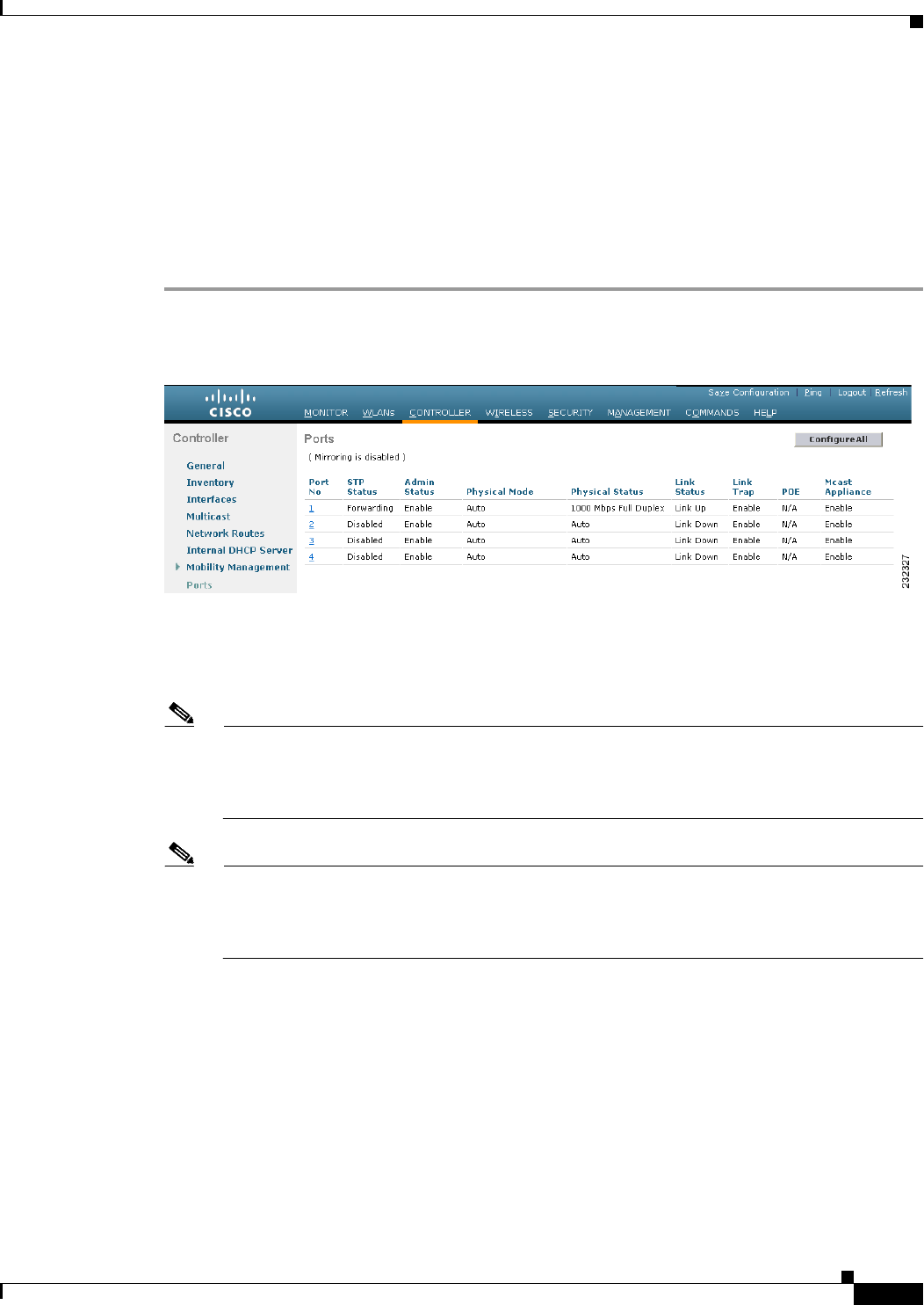
3-23
Cisco Wireless LAN Controller Configuration Guide
OL-21524-02
Chapter 3 Configuring Ports and Interfaces
Configuring Ports
Configuring Ports
The controller’s ports are preconfigured with factory-default settings designed to make the controllers’
ports operational without additional configuration. However, you can view the status of the controller’s
ports and edit their configuration parameters at any time.
To use the GUI to view the status of the controller’s ports and make any configuration changes if
necessary, follow these steps:
Step 1 Choose Controller > Ports to open the Ports page (see Figure 3-9).
Figure 3-9 Ports Page
This page shows the current configuration for each of the controller’s ports.
If you want to change the settings of any port, click the number for that specific port. The Port >
Configure page appears (see Figure 3-10).
Note If the management and AP-manager interfaces are mapped to the same port and are members of
the same VLAN, you must disable the WLAN before making a port-mapping change to either
interface. If the management and AP-manager interfaces are assigned to different VLANs, you
do not need to disable the WLAN.
Note The number of parameters available on the Port > Configure page depends on your controller
type. For instance, Cisco 2100 Series Controller and the controller in a Cisco Integrated Services
Router have fewer configurable parameters than a Cisco 4400 Series Controller, which is shown
in Figure 3-10.
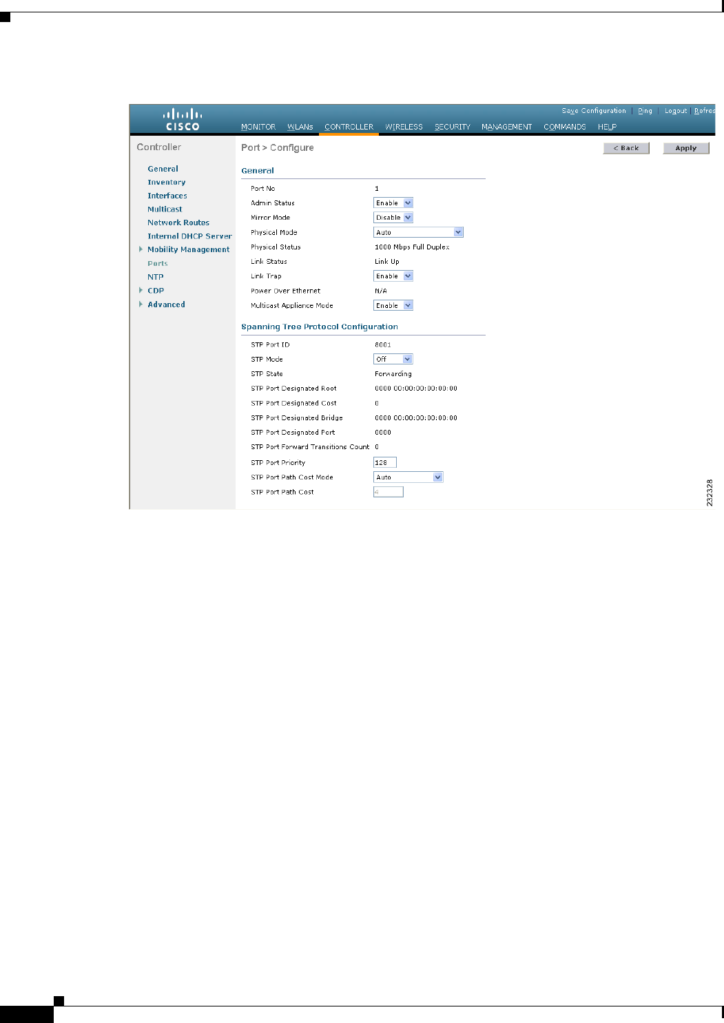
3-24
Cisco Wireless LAN Controller Configuration Guide
OL-21524-02
Chapter 3 Configuring Ports and Interfaces
Configuring Ports
Figure 3-10 Port > Configure Page

3-25
Cisco Wireless LAN Controller Configuration Guide
OL-21524-02
Chapter 3 Configuring Ports and Interfaces
Configuring Ports
Table 3-2 shows the current status of the port.
Ta b l e 3-2 Port Status
Parameter Description
Port Number Number of the current port.
Admin Status Current state of the port.
Values: Enable or Disable
Physical Mode Configuration of the port physical interface. The mode varies by the
controller type.
Values: Auto, 100 Mbps Full Duplex, 100 Mbps Half Duplex,
10 Mbps Full Duplex, or 10 Mbps Half Duplex
Physical Status The data rate being used by the port. The available data rates vary based
on controller type.
Controller Available Data Rates
5500 series 1000 Mbps full duplex
4400 series 1000 Mbps full duplex
2100 series 10 or 100 Mbps, half or full
duplex
WiSM 1000 Mbps full duplex
Controller network module 100 Mbps full duplex
Catalyst 3750G Integrated Wireless
LAN Controller Switch
1000 Mbps full duplex
Link Status Port’s link status.
Values: Link Up or Link Down
Link Trap Whether the port is set to send a trap when the link status changes.
Values: Enable or Disable
Power over Ethernet (PoE) If the connecting device is equipped to receive power through the
Ethernet cable and if so, provides –48 VDC.
Values: Enable or Disable
Note Some older Cisco access points do not draw PoE even if it is
enabled on the controller port. In such cases, contact the Cisco
Technical Assistance Center (TAC).
Note The controller in the Catalyst 3750G Integrated Wireless LAN
Controller Switch supports PoE on all ports.

3-26
Cisco Wireless LAN Controller Configuration Guide
OL-21524-02
Chapter 3 Configuring Ports and Interfaces
Configuring Ports
Step 2 Table 3-3 lists and describes the port’s configurable parameters. Follow the instructions in the table to
make any desired changes.
Step 3 Click Apply to commit your changes.
Step 4 Click Save Configuration to save your changes.
Ta b l e 3-3 Port Parameters
Parameter Description
Admin Status Enables or disables the flow of traffic through the port.
Options: Enable or Disable
Default: Enable
Note Administratively disabling the port on a controller does not
affect the port’s link status. The link can be brought down only
by other Cisco devices. On other Cisco products, however,
administratively disabling a port brings the link down.
Physical Mode Determines whether the port’s data rate is set automatically or specified
by the user. The supported data rates vary based on the controller type.
Default: Auto
Controller Supported Data Rates
5500 series Fixed 1000 Mbps full duplex
4400 series Auto or 1000 Mbps full duplex
2100 series Auto or 10 or 100 Mbps, half or
full duplex
WiSM Auto or 1000 Mbps full duplex
Controller network module Auto or 100 Mbps full duplex
Catalyst 3750G Integrated Wireless
LAN Controller Switch
Auto or 1000 Mbps full duplex
Note Make sure that a duplex mismatch does not exist between a
Cisco 2100 series Controller and the Catalyst switch. A duplex
mismatch is a situation where the switch operates at full duplex
and the connected device operates at half duplex or vice versa.
The results of a duplex mismatch are extremely slow
performance, intermittent connectivity, and loss of connection.
Other possible causes of data link errors at full duplex are bad
cables, faulty switch ports, or client software or hardware
issues.
Link Trap Causes the port to send a trap when the port’s link status changes.
Options: Enable or Disable
Default: Enable
Multicast Appliance Mode Enables or disables the multicast appliance service for this port.
Options: Enable or Disable
Default: Enable

3-27
Cisco Wireless LAN Controller Configuration Guide
OL-21524-02
Chapter 3 Configuring Ports and Interfaces
Configuring Ports
Step 5 Click Back to return to the Ports page and review your changes.
Step 6 Repeat this procedure for each additional port that you want to configure.
Step 7 Go to the following sections if you want to configure the controller’s ports for these advanced features:
• For port mirroring, see the “Configuring Port Mirroring” section on page 3-27
• For the Spanning Tree Protocol (STP), see the “Configuring Spanning Tree Protocol” section on
page 3-28.
Note Users will be prompted with a warning message when the following events occur:
1. When the traffic rate from the data ports exceeds 300 Mbps.
2. When the traffic rate from the data ports exceeds 250 Mbps constantly for one minute.
3. When the traffic rate from the data ports falls back to normal from one of the above state for 1 minute.
Configuring Port Mirroring
Mirror mode enables you to duplicate to another port all of the traffic originating from or terminating at
a single client device or access point. It is useful in diagnosing specific network problems. Mirror mode
should be enabled only on an unused port as any connections to this port become unresponsive.
Note The Cisco 5500 Series Controllers, Cisco 2100 Series Controller, controller network modules, and Cisco
WiSM controllers do not support mirror mode. Also, a controller’s service port cannot be used as a
mirrored port.
Note Port mirroring is not supported when link aggregation (LAG) is enabled on the controller.
Note We recommend that you do not mirror traffic from one controller port to another as this setup could cause
network problems.
To enable port mirroring, follow these steps:
Step 1 Choose Controller > Ports to open the Ports page (see Figure 3-9).
Step 2 Click the number of the unused port for which you want to enable mirror mode. The Port > Configure
page appears (see Figure 3-10).
Step 3 Set the Mirror Mode parameter to Enable.
Step 4 Click Apply to commit your changes.
Step 5 Perform one of the following:

3-28
Cisco Wireless LAN Controller Configuration Guide
OL-21524-02
Chapter 3 Configuring Ports and Interfaces
Configuring Ports
• Follow these steps if you want to choose a specific client device that will mirror its traffic to the port
you selected on the controller:
a. Choose Wireless > Clients to open the Clients page.
b. Click the MAC address of the client for which you want to enable mirror mode. The Clients >
Detail page appears.
c. Under Client Details, set the Mirror Mode parameter to Enable.
• Follow these steps if you want to choose an access point that will mirror its traffic to the port you
selected on the controller:
a. Choose Wireless > Access Points > All APs to open the All APs page.
b. Click the name of the access point for which you want to enable mirror mode. The All APs >
Details page appears.
c. Choose the Advanced tab.
d. Set the Mirror Mode parameter to Enable.
Step 6 Click Save Configuration to save your changes.
Configuring Spanning Tree Protocol
Spanning Tree Protocol (STP) is a Layer 2 link management protocol that provides path redundancy
while preventing loops in the network. For a Layer 2 Ethernet network to function properly, only one
active path can exist between any two network devices. STP allows only one active path at a time
between network devices but establishes redundant links as a backup if the initial link should fail.
The spanning-tree algorithm calculates the best loop-free path throughout a Layer 2 network.
Infrastructure devices such as controllers and switches send and receive spanning-tree frames, called
bridge protocol data units (BPDUs), at regular intervals. The devices do not forward these frames but
use them to construct a loop-free path.
Multiple active paths among end stations cause loops in the network. If a loop exists in the network, end
stations might receive duplicate messages. Infrastructure devices might also learn end-station MAC
addresses on multiple Layer 2 interfaces. These conditions result in an unstable network.
STP defines a tree with a root bridge and a loop-free path from the root to all infrastructure devices in
the Layer 2 network.
Note STP discussions use the term root to describe two concepts: the controller on the network that serves as
a central point in the spanning tree is called the root bridge, and the port on each controller that provides
the most efficient path to the root bridge is called the root port. The root bridge in the spanning tree is
called the spanning-tree root.
STP forces redundant data paths into a standby (blocked) state. If a network segment in the spanning tree
fails and a redundant path exists, the spanning-tree algorithm recalculates the spanning-tree topology
and activates the standby path.
When two ports on a controller are part of a loop, the spanning-tree port priority and path cost settings
determine which port is put in the forwarding state and which is put in the blocking state. The port
priority value represents the location of a port in the network topology and how well it is located to pass
traffic. The path cost value represents the media speed.

3-29
Cisco Wireless LAN Controller Configuration Guide
OL-21524-02
Chapter 3 Configuring Ports and Interfaces
Configuring Ports
The controller maintains a separate spanning-tree instance for each active VLAN configured on it. A
bridge ID, consisting of the bridge priority and the controller’s MAC address, is associated with each
instance. For each VLAN, the controller with the lowest controller ID becomes the spanning-tree root
for that VLAN.
STP is disabled for the controller’s distribution system ports by default. The following sections provide
instructions for configuring STP for your controller using either the GUI or CLI.
Note STP cannot be configured for Cisco 2100 Series Controllers, Cisco 5500 Series Controllers, and the
controller in the Catalyst 3750G Integrated Wireless LAN Controller Switch.
Using the GUI to Configure Spanning Tree Protocol
To configure STP using the controller GUI, follow these steps:
Step 1 Choose Controller > Ports to open the Ports page (see Figure 3-9).
Step 2 Click the number of the port for which you want to configure STP. The Port > Configure page appears
(see Figure 3-10). This page shows the STP status of the port and enables you to configure STP
parameters.
Table 3-4 interprets the current STP status of the port.
Ta b l e 3-4 Port Spanning Tree Status
Parameter Description
STP Port ID Number of the port for which STP is enabled or disabled.
STP State Port’s current STP state. It controls the action that a port takes upon
receiving a frame.
Values: Disabled, Blocking, Listening, Learning, Forwarding, and
Broken
STP State Description
Disabled Port that does not participate in spanning tree because the
port is shut down, the link is down, or STP is not enabled
for this port.
Blocking Port that does not participate in frame forwarding.
Listening First transitional state after the blocking state when STP
determines that the port should participate in frame
forwarding.
Learning Port that prepares to participate in frame forwarding.
Forwarding Port that forwards frames.
Broken Port that is malfunctioning.
STP Port Designated Root Unique identifier of the root bridge in the configuration BPDUs.
STP Port Designated Cost Path cost of the designated port.
STP Port Designated Bridge Identifier of the bridge that the port considers to be the designated
bridge for this port.

3-30
Cisco Wireless LAN Controller Configuration Guide
OL-21524-02
Chapter 3 Configuring Ports and Interfaces
Configuring Ports
Step 3 Table 3-5 lists and describes the port’s configurable STP parameters. Follow the instructions in the table
to make any desired changes.
STP Port Designated Port Port identifier on the designated bridge for this port.
STP Port Forward Transitions
Count
Number of times that the port has transitioned from the learning state
to the forwarding state.
Ta b l e 3-5 Port Spanning Tree Parameters
Parameter Description
STP Mode STP administrative mode associated with this port.
Options: Off, 802.1D, or Fast
Default: Off
STP Mode Description
Off Disables STP for this port.
802.1D Enables this port to participate in the
spanning tree and go through all of the
spanning tree states when the link state
transitions from down to up.
Fast Enables this port to participate in the
spanning tree and puts it in the forwarding
state when the link state transitions from
down to up more quickly than when the
STP mode is set to 802.1D.
Note In this state, the forwarding delay
timer is ignored on link up.
STP Port Priority Location of the port in the network topology and how well the port is
located to pass traffic.
Range: 0 to 255
Default: 128
STP Port Path Cost Mode Whether the STP port path cost is set automatically or specified by the
user. If you choose User Configured, you also need to set a value for the
STP Port Path Cost parameter.
Range: Auto or User Configured
Default: Auto
Table 3-4 Port Spanning Tree Status (continued)
Parameter Description
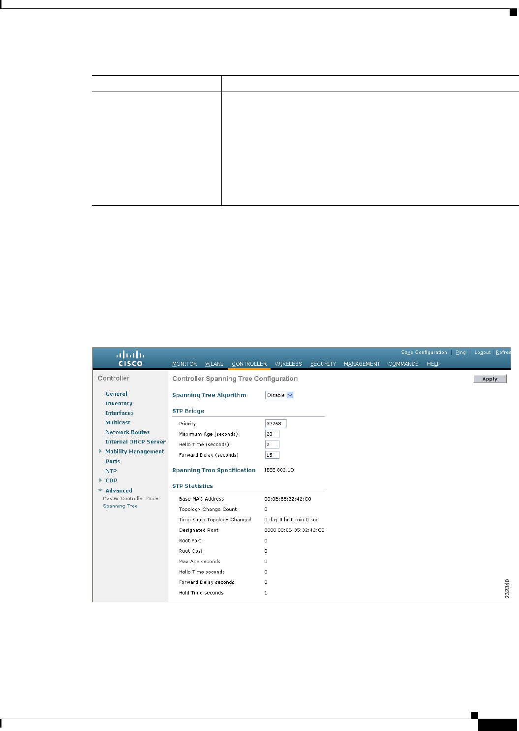
3-31
Cisco Wireless LAN Controller Configuration Guide
OL-21524-02
Chapter 3 Configuring Ports and Interfaces
Configuring Ports
Step 4 Click Apply to commit your changes.
Step 5 Click Save Configuration to save your changes.
Step 6 Click Back to return to the Ports page.
Step 7 Repeat Step 2 through Step 6 for each port for which you want to enable STP.
Step 8 Choose Controller > Advanced > Spanning Tree to open the Controller Spanning Tree Configuration
page (see Figure 3-11).
Figure 3-11 Controller Spanning Tree Configuration Page
This page allows you to enable or disable the spanning tree algorithm for the controller, modify its
characteristics, and view the STP status. Table 3-6 interprets the current STP status for the controller.
STP Port Path Cost Speed at which traffic is passed through the port. This parameter must
be set if the STP Port Path Cost Mode parameter is set to User
Configured.
Options: 0 to 65535
Default: 0, which causes the cost to be adjusted for the speed of the
port when the link comes up.
Note Typically, a value of 100 is used for 10-Mbps ports and 19 for
100-Mbps ports.
Table 3-5 Port Spanning Tree Parameters (continued)
Parameter Description

3-32
Cisco Wireless LAN Controller Configuration Guide
OL-21524-02
Chapter 3 Configuring Ports and Interfaces
Configuring Ports
Step 9 See Table 3-7 for the controller’s configurable STP parameters. Follow the instructions in the table to
make any desired changes.
Ta b l e 3-6 Controller Spanning Tree Status
Parameter Description
Spanning Tree Specification STP version being used by the controller. Currently, only an IEEE 802.1D
implementation is available.
Base MAC Address MAC address used by this bridge when it must be referred to in a unique
fashion. When it is concatenated with dot1dStpPriority, a unique bridge
identifier is formed that is used in STP.
Topology Change Count Total number of topology changes detected by this bridge since the
management entity was last reset or initialized.
Time Since Topology
Changed
Time (in days, hours, minutes, and seconds) since a topology change
was detected by the bridge.
Designated Root Bridge identifier of the spanning tree root. This value is used as the
Root Identifier parameter in all configuration BPDUs originated by this
node.
Root Port Number of the port that offers the lowest cost path from this bridge to
the root bridge.
Root Cost Cost of the path to the root as seen from this bridge.
Max Age (seconds) Maximum age of STP information learned from the network on any
port before it is discarded.
Hello Time (seconds) Amount of time between the transmission of configuration BPDUs by
this node on any port when it is the root of the spanning tree or trying
to become so. This is the actual value that this bridge is currently using.
Forward Delay (seconds) Value that controls how fast a port changes its spanning tree state when
moving toward the forwarding state. It determines how long the port
stays in each of the listening and learning states that precede the
forwarding state. This value is also used, when a topology change has
been detected and is underway, to age all dynamic entries in the
forwarding database.
Note This value is the actual value that this bridge is currently using,
in contrast to Stp Bridge Forward Delay, which is the value that
this bridge and all others would start using if this bridge were
to become the root.
Hold Time (seconds) Minimum time period to elapse between the transmission of
configuration BPDUs through a given LAN port.
Note Only one configuration BPDU can be transmitted in any hold
time period.

3-33
Cisco Wireless LAN Controller Configuration Guide
OL-21524-02
Chapter 3 Configuring Ports and Interfaces
Configuring Ports
Step 10 Click Apply to commit your changes.
Step 11 Click Save Configuration to save your changes.
Using the CLI to Configure Spanning Tree Protocol
To configure STP using the CLI, follow these steps:
Step 1 Enter the show spanningtree port command and the show spanningtree switch command to view the
current STP status.
Step 2 If STP is enabled, you must disable it before you can change STP settings. Enter the config
spanningtree switch mode disable command to disable STP on all ports.
Step 3 Enter one of these commands to configure the STP port administrative mode:
• config spanningtree port mode 802.1d {port-number | all}
• config spanningtree port mode fast {port-number | all}
• config spanningtree port mode off {port-number | all}
Ta b l e 3-7 Controller Spanning Tree Parameters
Parameter Description
Spanning Tree Algorithm Algorithm that you use to enable or disable STP for the controller.
Options: Enable or Disable
Default: Disable
Priority Location of the controller in the network topology and how well the
controller is located to pass traffic.
Range: 0 to 65535
Default: 32768
Maximum Age (seconds) Length of time that the controller stores protocol information received
on a port.
Range: 6 to 40 seconds
Default: 20 seconds
Hello Time (seconds) Length of time that the controller broadcasts hello messages to other
controllers.
Options: 1 to 10 seconds
Default: 2 seconds
Forward Delay (seconds) Length of time that each of the listening and learning states lasts before
the port begins forwarding.
Options: 4 to 30 seconds
Default: 15 seconds

3-34
Cisco Wireless LAN Controller Configuration Guide
OL-21524-02
Chapter 3 Configuring Ports and Interfaces
Using the Cisco 5500 Series Controller USB Console Port
Step 4 Enter one of these commands to configure the STP port path cost on the STP ports:
• config spanningtree port pathcost 1-65535 {port-number | all}—Specifies a path cost from 1 to
65535 to the port.
• config spanningtree port mode pathcost auto {port-number | all}—Enables the STP algorithm to
automatically assign the path cost. This is the default setting.
Step 5 Enter the config spanningtree port priority command 0-255 port-number to configure the port priority
on STP ports. The default priority is 128.
Step 6 If necessary, enter the config spanningtree switch bridgepriority command 0-65535 to configure the
controller’s STP bridge priority. The default bridge priority is 32768.
Step 7 If necessary, enter the config spanningtree switch forwarddelay command 4-30 to configure the
controller’s STP forward delay in seconds. The default forward delay is 15 seconds.
Step 8 If necessary, enter the config spanningtree switch hellotime command 1-10 to configure the
controller’s STP hello time in seconds. The default hello time is 2 seconds.
Step 9 If necessary, enter the config spanningtree switch maxage command 6-40 to configure the controller’s
STP maximum age. The default maximum age is 20 seconds.
Step 10 After you configure STP settings for the ports, enter the config spanningtree switch mode enable
command to enable STP for the controller. The controller automatically detects logical network loops,
places redundant ports on standby, and builds a network with the most efficient pathways.
Step 11 Enter the save config command to save your settings.
Step 12 Enter the show spanningtree port command and the show spanningtree switch command to verify that
your changes have been saved.
Using the Cisco 5500 Series Controller USB Console Port
The USB console port on the Cisco 5500 Series Controllers connects directly to the USB connector of
a PC using a USB Type A-to-5-pin mini Type B cable.
Note The 4-pin mini Type B connector is easily confused with the 5-pin mini Type B connector. They are not
compatible. Only the 5-pin mini Type B connector can be used.
For operation with Microsoft Windows, the Cisco Windows USB console driver must be installed on any
PC connected to the console port. With this driver, you can plug and unplug the USB cable into and from
the console port without affecting Windows HyperTerminal operations.
Note Only one console port can be active at a time. When a cable is plugged into the USB console port, the
RJ-45 port becomes inactive. Conversely, when the USB cable is removed from the USB port, the RJ-45
port becomes active.
USB Console OS Compatibility
These operating systems are compatible with the USB console:
• Microsoft Windows 2000, XP, Vista (Cisco Windows USB console driver required)
• Apple Mac OS X 10.5.2 (no driver required)

3-35
Cisco Wireless LAN Controller Configuration Guide
OL-21524-02
Chapter 3 Configuring Ports and Interfaces
Using the Cisco 5500 Series Controller USB Console Port
• Linux (no driver required)
To install the Cisco Windows USB console driver, follow these steps:
Step 1 Download the USB_Console.inf driver file as follows:
a. Click this URL to go to the Software Center:
http://tools.cisco.com/support/downloads/go/Redirect.x?mdfid=278875243
b. Click Wireless LAN Controllers.
c. Click Standalone Controllers.
d. Click Cisco 5500 Series Wireless LAN Controllers.
e. Click Cisco 5508 Wireless LAN Controller.
f. Choose the USB driver file.
g. Save the file to your hard drive.
Step 2 Connect the Type A connector to a USB port on your PC.
Step 3 Connect the mini Type B connector to the USB console port on the controller.
Step 4 When prompted for a driver, browse to the USB_Console.inf file on your PC. Follow the prompts to
install the USB driver.
Note Some systems might also require an additional system file. You can download the Usbser.sys file
from this URL:
http://support.microsoft.com/kb/918365
The USB driver is mapped to COM port 6. Some terminal emulation programs do not recognize a port
higher than COM 4. If necessary, change the Cisco USB systems management console COM port to an
unused port of COM 4 or lower. To do so, follow these steps:
Step 1 From your Windows desktop, right-click My Computer and choose Manage.
Step 2 From the list on the left side, choose Device Manager.
Step 3 From the device list on the right side, double-click Ports (COM & LPT).
Step 4 Right-click Cisco USB System Management Console 0108 and choose Properties.
Step 5 Click the Port Settings tab and click the Advanced button.
Step 6 From the COM Port Number drop-down list, choose an unused COM port of 4 or lower.
Step 7 Click OK to save and then close the Advanced Settings dialog box.
Step 8 Click OK to save and then close the Communications Port Properties dialog box.

3-36
Cisco Wireless LAN Controller Configuration Guide
OL-21524-02
Chapter 3 Configuring Ports and Interfaces
Choosing Between Link Aggregation and Multiple AP-Manager Interfaces
Choosing Between Link Aggregation and Multiple AP-Manager
Interfaces
Cisco 4400 Series Controllers can support up to 48 access points per port. However, you can configure
your Cisco 4400 Series Controller to support more access points by using link aggregation (LAG) or
configuring dynamic AP-managers on each Gigabit Ethernet port. Cisco 5500 Series Controllers have
no restrictions on the number of access points per port, but we recommend using LAG or multiple
AP-manager interfaces on each Gigabit Ethernet port to automatically balance the load.
The following factors should help you decide which method to use if your controller is set for Layer 3
operation:
• With LAG, all of the controller ports need to connect to the same neighbor switch. If the neighbor
switch goes down, the controller loses connectivity.
• With multiple AP-manager interfaces, you can connect your ports to different neighbor devices. If
one of the neighbor switches goes down, the controller still has connectivity. However, using
multiple AP-manager interfaces presents certain challenges (as discussed in the “Configuring
Multiple AP-Manager Interfaces” section) when port redundancy is a concern.
Follow the instructions on the page indicated for the method you want to use:
• Link aggregation, page 3-36
• Multiple AP-manager interfaces, page 3-42
Enabling Link Aggregation
Link aggregation (LAG) is a partial implementation of the 802.3ad port aggregation standard. It bundles
all of the controller’s distribution system ports into a single 802.3ad port channel, thereby reducing the
number of IP addresses needed to configure the ports on your controller. When LAG is enabled, the system
dynamically manages port redundancy and load balances access points transparently to the user.
Note The Cisco 2100 Series Controller do not support LAG.
Note You can bundle all four ports on a Cisco 4404 Controller (or two on a 4402 controller) or all eight ports
on a Cisco 5508 Controller into a single link.
Cisco 5500 Series Controllers support LAG in software release 6.0 or later releases, Cisco 4400 Series
Controllers support LAG in software release 3.2 or later releases, and LAG is enabled automatically on
the controllers within the Cisco WiSM and the Catalyst 3750G Integrated Wireless LAN Controller
Switch. Without LAG, each distribution system port on a Cisco 4400 Series Controller supports up to 48
access points. With LAG enabled, a Cisco 4402 Controller’s logical port supports up to 50 access points,
a Cisco 4404 Controller’s logical port supports up to 100 access points, and the logical port on the
Catalyst 3750G Integrated Wireless LAN Controller Switch and on each Cisco WiSM controller
supports up to 150 access points.
Figure 3-12 shows LAG.
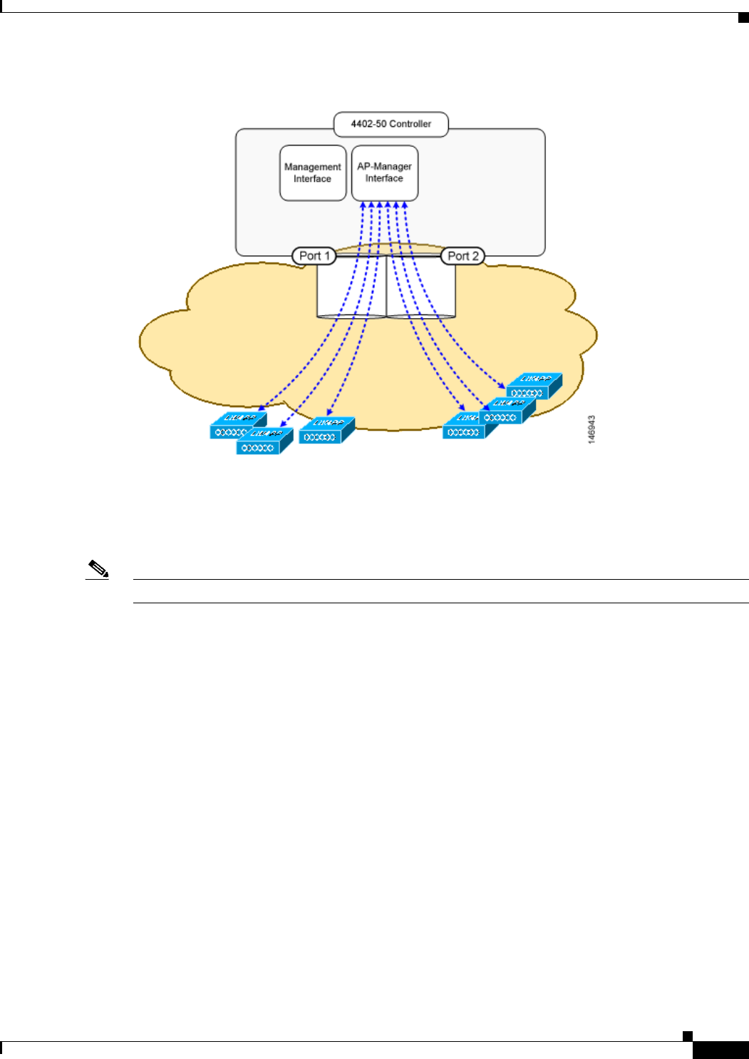
3-37
Cisco Wireless LAN Controller Configuration Guide
OL-21524-02
Chapter 3 Configuring Ports and Interfaces
Enabling Link Aggregation
Figure 3-12 Link Aggregation
LAG simplifies controller configuration because you no longer need to configure primary and secondary
ports for each interface. If any of the controller ports fail, traffic is automatically migrated to one of the
other ports. As long as at least one controller port is functioning, the system continues to operate, access
points remain connected to the network, and wireless clients continue to send and receive data.
Note LAG is supported across switches.
Terminating on two different modules within a single Catalyst 6500 series switch provides redundancy
and ensures that connectivity between the switch and the controller is maintained when one module fails.
Figure 3-13 shows this use of redundant modules. A Cisco 4402-50 Controller is connected to two
different Gigabit modules (slots 2 and 3) within the Catalyst 6500 Series Switch. The controller’s port 1
is connected to Gigabit interface 3/1, and the controller’s port 2 is connected to Gigabit interface 2/1 on
the Catalyst 6500 series switch. Both switch ports are assigned to the same channel group.
When a Cisco 5500 Series Controller, Cisco 4404 Controller, or WiSM controller module LAG port is
connected to a Catalyst 3750G or a 6500 or 7600 channel group employing load balancing, note the
following:
• LAG requires the EtherChannel to be configured for the on mode on both the controller and the
Catalyst switch.
• Once the EtherChannel is configured as on at both ends of the link, it does not matter if the Catalyst
switch is configured for either Link Aggregation Control Protocol (LACP) or Cisco proprietary Port
Aggregation Protocol (PAgP) because no channel negotiation is done between the controller and the
switch. Additionally, LACP and PAgP are not supported on the controller.
• The load-balancing method configured on the Catalyst switch must be a load-balancing method that
terminates all IP datagram fragments on a single controller port. Not following this recommendation
may result in problems with access point association.

3-38
Cisco Wireless LAN Controller Configuration Guide
OL-21524-02
Chapter 3 Configuring Ports and Interfaces
Enabling Link Aggregation
• The recommended load-balancing method for Catalyst switches is src-dst-ip (enter the
port-channel load-balance src-dst-ip command).
• The Catalyst 6500 series switches running in PFC3 or PFC3CXL mode implement enhanced
EtherChannel load balancing. The enhanced EtherChannel load balancing adds the VLAN number
to the hash function, which is incompatible with LAG. From Release 12.2(33)SXH and later
releases, Catalyst 6500 IOS software offers the exclude vlan keyword to the port-channel
load-balance command to implement src-dst-ip load distribution. See the Cisco IOS Interface and
Hardware Component Command Reference for more information.
• Enter the show platform hardware pfc mode command on the Catalyst 6500 switch to confirm the
PFC operating mode.
The following example shows a Catalyst 6500 series switch in PFC3B mode when you enter the
global configuration port-channel load-balance src-dst-ip command for proper LAG
functionality:
# show platform hardware pfc mode PFC operating mode
PFC operating mode : PFC3B
# show EtherChannel load-balance
EtherChannel Load-Balancing Configuration:
src-dst-ip
The following example shows Catalyst 6500 series switch in PFC3C mode when you enter the
exclude vlan keyword in the port-channel load- balance src-dst-ip exclude vlan command:
# show platform hardware pfc mode
PFC operating mode : PFC3C
# show EtherChannel load-balance
EtherChannel Load-Balancing Configuration:
src-ip enhanced
# mpls label-ip
• If the recommended load-balancing method cannot be configured on the Catalyst switch, then
configure the LAG connection as a single member link or disable LAG on the controller.
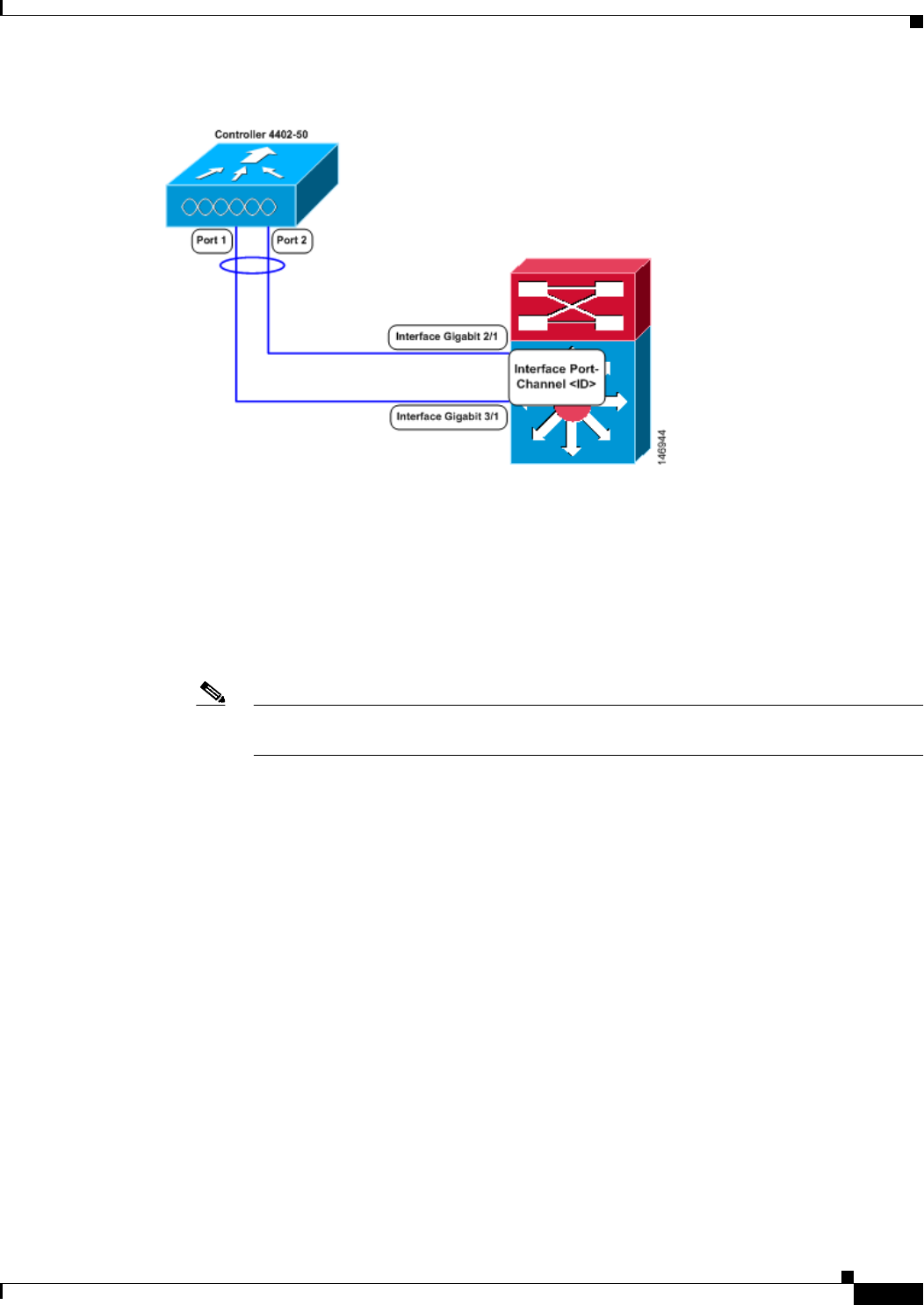
3-39
Cisco Wireless LAN Controller Configuration Guide
OL-21524-02
Chapter 3 Configuring Ports and Interfaces
Enabling Link Aggregation
Figure 3-13 Link Aggregation with the Catalyst 6500 Series Neighbor Switch
Link Aggregation Guidelines
Follow these guidelines when using LAG:
• You cannot configure the controller’s ports into separate LAG groups. Only one LAG group is
supported per controller. Therefore, you can connect a controller in LAG mode to only one neighbor
device.
Note The two internal Gigabit ports on the controller within the Catalyst 3750G Integrated
Wireless LAN Controller Switch are always assigned to the same LAG group.
• When you enable LAG or make any changes to the LAG configuration, you must immediately reboot
the controller.
• When you enable LAG, you can configure only one AP-manager interface because only one logical
port is needed. LAG removes the requirement for supporting multiple AP-manager interfaces.
• When you enable LAG, all dynamic AP-manager interfaces and untagged interfaces are deleted, and
all WLANs are disabled and mapped to the management interface. Also, the management, static
AP-manager, and VLAN-tagged dynamic interfaces are moved to the LAG port.
• Multiple untagged interfaces to the same port are not allowed.
• When you enable LAG, you cannot create interfaces with a primary port other than 29.
• When you enable LAG, all ports participate in LAG by default. You must configure LAG for all of
the connected ports in the neighbor switch.
• When you enable LAG on the Cisco WiSM, you must enable port-channeling/EtherChanneling for
all of the controller’s ports on the switch.
• When you enable LAG, port mirroring is not supported.
• When you enable LAG, if any single link goes down, traffic migrates to the other links.
• When you enable LAG, only one functional physical port is needed for the controller to pass client
traffic.
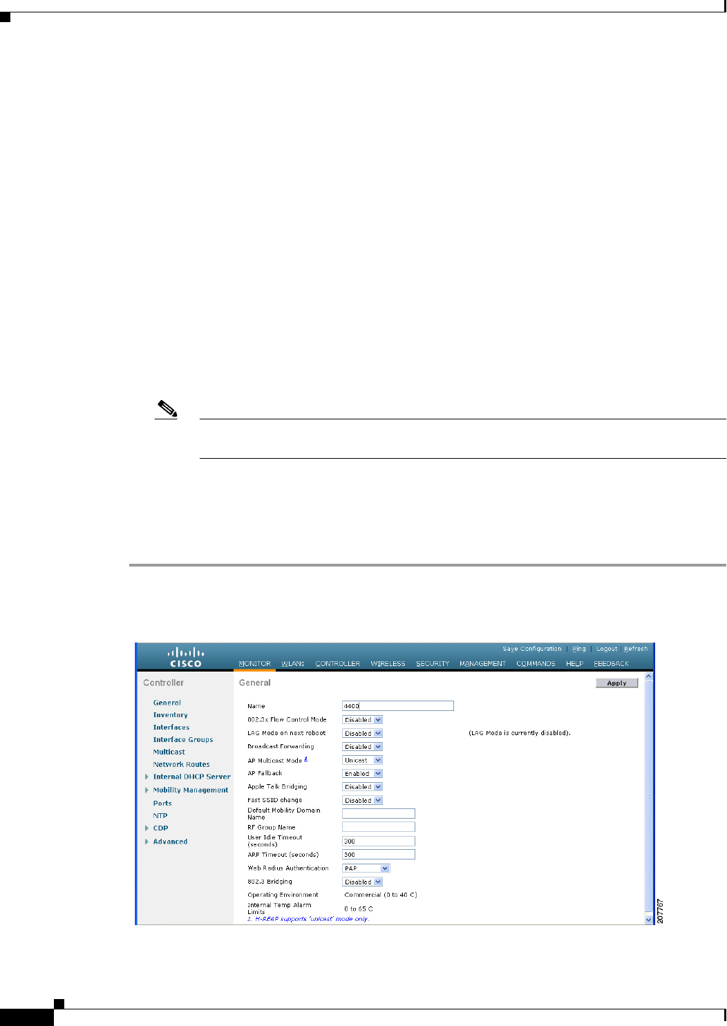
3-40
Cisco Wireless LAN Controller Configuration Guide
OL-21524-02
Chapter 3 Configuring Ports and Interfaces
Enabling Link Aggregation
• When you enable LAG, access points remain connected to the switch, and data service for users
continues uninterrupted.
• When you enable LAG, you eliminate the need to configure primary and secondary ports for each
interface.
• When you enable LAG, the controller sends packets out on the same port on which it received them.
If a CAPWAP packet from an access point enters the controller on physical port 1, the controller
removes the CAPWAP wrapper, processes the packet, and forwards it to the network on physical
port 1. This may not be the case if you disable LAG.
• When you disable LAG, the management, static AP-manager, and dynamic interfaces are moved to
port 1.
• When you disable LAG, you must configure primary and secondary ports for all interfaces.
• When you disable LAG, you must assign an AP-manager interface to each port on the controller.
Otherwise, access points are unable to join.
• Cisco 5500 and 4400 Series Controllers support a single static link aggregation bundle.
• LAG is typically configured using the Startup Wizard, but you can enable or disable it at any time
through either the GUI or CLI.
Note LAG is enabled by default and is the only option on the WiSM controller and the controller
in the Catalyst 3750G Integrated Wireless LAN Controller Switch.
Using the GUI to Enable Link Aggregation
To enable LAG on your controller using the controller GUI, follow these steps:
Step 1 Choose Controller > General to open the General page (see Figure 3-14).
Figure 3-14 General Page
Step 2 Set the LAG Mode on Next Reboot parameter to Enabled.

3-41
Cisco Wireless LAN Controller Configuration Guide
OL-21524-02
Chapter 3 Configuring Ports and Interfaces
Enabling Link Aggregation
Note Choose Disabled if you want to disable LAG. LAG is disabled by default on the Cisco 5500 and
4400 series controllers but enabled by default on the Cisco WiSM and the controller in the
Catalyst 3750G Integrated Wireless LAN Controller Switch.
Step 3 Click Apply to commit your changes.
Step 4 Click Save Configuration to save your changes.
Step 5 Reboot the controller.
Step 6 Assign the WLAN to the appropriate VLAN.
Using the CLI to Enable Link Aggregation
To enable LAG on your controller using the CLI, follow these steps:
Step 1 Enter the config lag enable command to enable LAG.
Note Enter the config lag disable command if you want to disable LAG.
Step 2 Enter the save config command to save your settings.
Step 3 Reboot the controller.
Using the CLI to Verify Link Aggregation Settings
To verify your LAG settings, enter this command:
show lag summary
Information similar to the following appears:
LAG Enabled
Configuring Neighbor Devices to Support Link Aggregation
The controller’s neighbor devices must also be properly configured to support LAG.
• Each neighbor port to which the controller is connected should be configured as follows:
interface GigabitEthernet <interface id>
switchport
channel-group <id> mode on
no shutdown
• The port channel on the neighbor switch should be configured as follows:
interface port-channel <id>
switchport
switchport trunk encapsulation dot1q

3-42
Cisco Wireless LAN Controller Configuration Guide
OL-21524-02
Chapter 3 Configuring Ports and Interfaces
Configuring Multiple AP-Manager Interfaces
switchport trunk native vlan <native vlan id>
switchport trunk allowed vlan <allowed vlans>
switchport mode trunk
no shutdown
Configuring Multiple AP-Manager Interfaces
Note Only Cisco 5500 Series Controllers and Cisco 4400 Series Controllers support the use of multiple
AP-manager interfaces.
When you create two or more AP-manager interfaces, each one is mapped to a different port (see
Figure 3-15). The ports should be configured in sequential order so that AP-manager interface 2 is on
port 2, AP-manager interface 3 is on port 3, and AP-manager interface 4 is on port 4.
Note AP-manager interfaces do not need to be on the same VLAN or IP subnet, and they may or may not be
on the same VLAN or IP subnet as the management interface. However, we recommend that you
configure all AP-manager interfaces on the same VLAN or IP subnet.
Note You must assign an AP-manager interface to each port on the controller.
Before an access point joins a controller, it sends out a discovery request. From the discovery response
that it receives, the access point can tell the number of AP-manager interfaces on the controller and the
number of access points on each AP-manager interface. The access point generally joins the AP-manager
with the least number of access points. In this way, the access point load is dynamically distributed
across the multiple AP-manager interfaces.
Note Access points may not be distributed completely evenly across all of the AP-manager interfaces, but a
certain level of load balancing occurs.
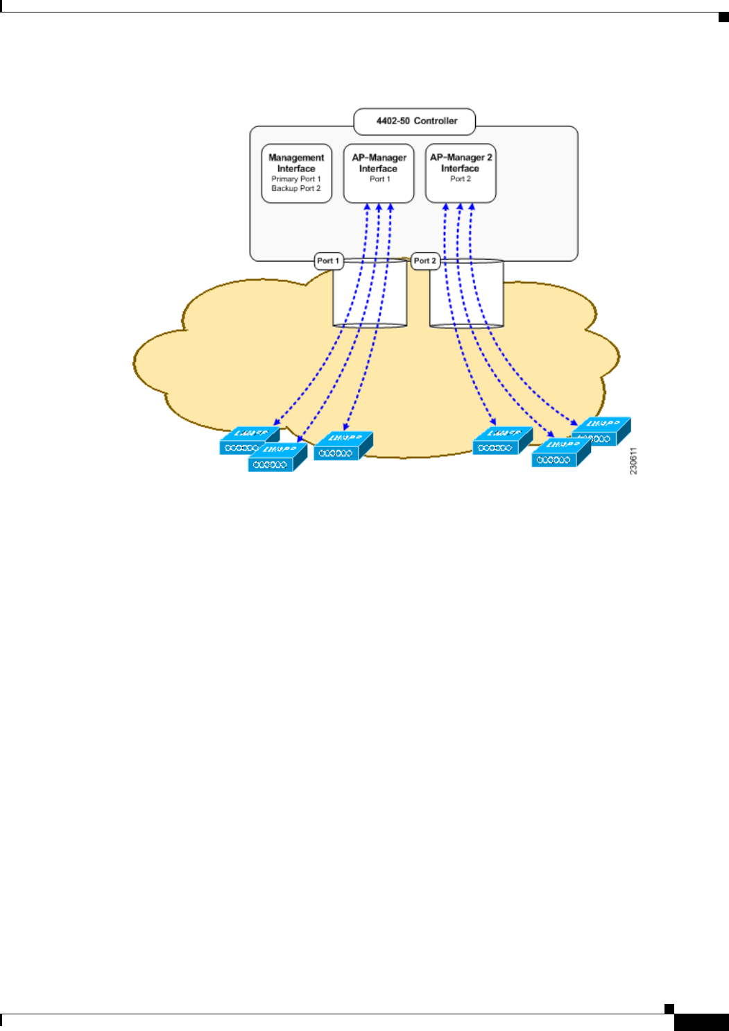
3-43
Cisco Wireless LAN Controller Configuration Guide
OL-21524-02
Chapter 3 Configuring Ports and Interfaces
Configuring Multiple AP-Manager Interfaces
Figure 3-15 Two AP-Manager Interfaces
Before implementing multiple AP-manager interfaces, you should consider how they would impact your
controller’s port redundancy.
Examples:
1. The Cisco 4402-50 Controller supports a maximum of 50 access points and has two ports. To support
the maximum number of access points, you would need to create two AP-manager interfaces (see
Figure 3-15) because a Cisco 4400 Series Controller can support only 48 access points on one port.
2. The Cisco 4404-100 Controller supports up to 100 access points and has four ports. To support the
maximum number of access points, you would need to create three (or more) AP-manager interfaces
(see Figure 3-16). If the port of one of the AP-manager interfaces fails, the controller clears the
access points’ state, and the access points must reboot to reestablish communication with the
controller using the normal controller join process. The controller no longer includes the failed
AP-manager interface in the CAPWAP or LWAPP discovery responses. The access points then
rejoin the controller and are load balanced among the available AP-manager interfaces.
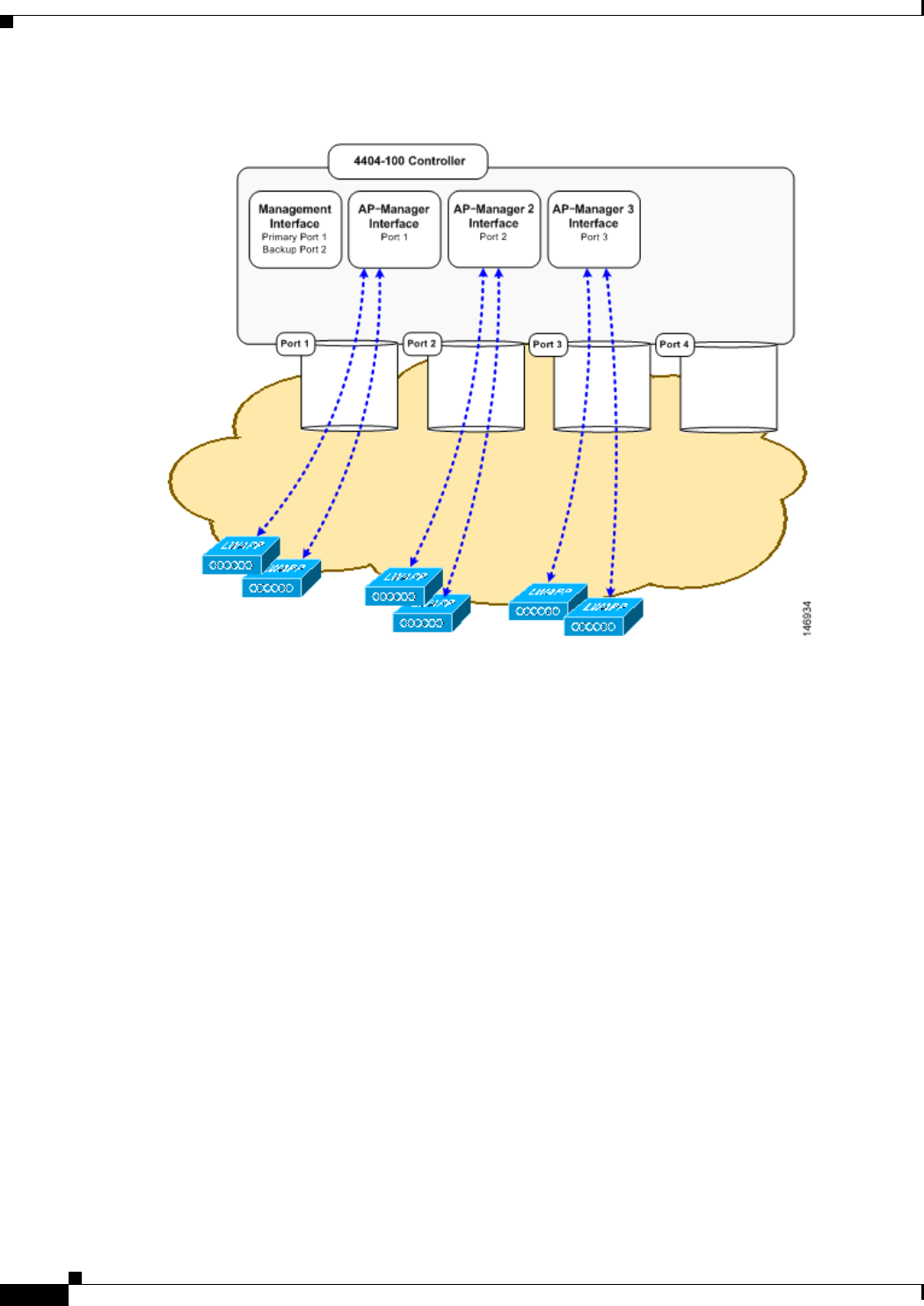
3-44
Cisco Wireless LAN Controller Configuration Guide
OL-21524-02
Chapter 3 Configuring Ports and Interfaces
Configuring Multiple AP-Manager Interfaces
Figure 3-16 Three AP-Manager Interfaces
Figure 3-17 shows the use of four AP-manager interfaces to support 100 access points on a Cisco
4400 Series Controller.
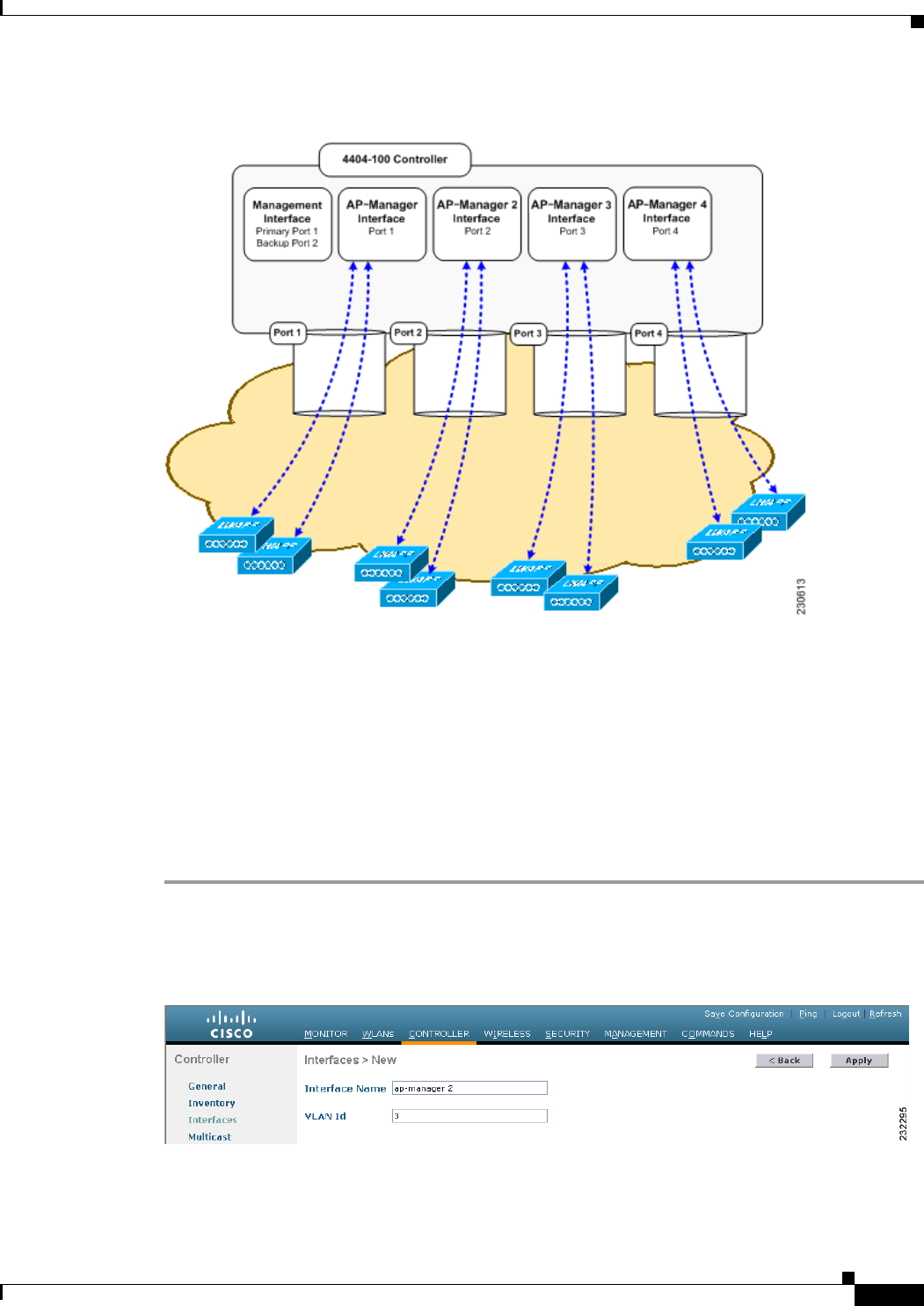
3-45
Cisco Wireless LAN Controller Configuration Guide
OL-21524-02
Chapter 3 Configuring Ports and Interfaces
Configuring Multiple AP-Manager Interfaces
Figure 3-17 Four AP-Manager Interfaces
This configuration has the advantage of load balancing all 100 access points evenly across all four
AP-manager interfaces. If one of the AP-manager interfaces fails, all of the access points connected
to the controller would be evenly distributed among the three available AP-manager interfaces. For
example, if AP-manager interface 2 fails, the remaining AP-manager interfaces (1, 3, and 4) would
each manage approximately 33 access points.
Using the GUI to Create Multiple AP-Manager Interfaces
To create multiple AP-manager interfaces using the controller GUI, follow these steps:
Step 1 Choose Controller > Interfaces to open the Interfaces page.
Step 2 Click New. The Interfaces > New page appears (see Figure 3-18).
Figure 3-18 Interfaces > New Page
Step 3 Enter an AP-manager interface name and a VLAN identifier.
Step 4 Click Apply to commit your changes. The Interfaces > Edit page appears (see Figure 3-19).
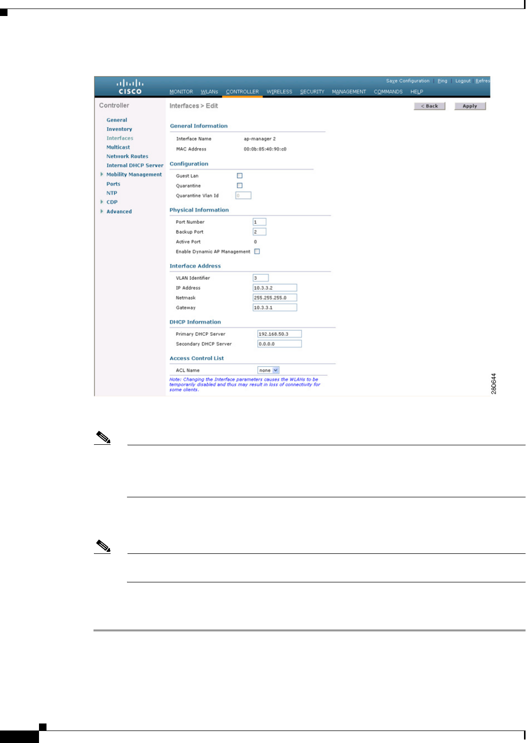
3-46
Cisco Wireless LAN Controller Configuration Guide
OL-21524-02
Chapter 3 Configuring Ports and Interfaces
Configuring Multiple AP-Manager Interfaces
Figure 3-19 Interfaces > Edit Page
Step 5 Enter the appropriate interface parameters.
Note Do not define a backup port for an AP-manager interface. Port redundancy is not supported for
AP-manager interfaces. If the AP-manager interface fails, all of the access points connected to
the controller through that interface are evenly distributed among the other configured
AP-manager interfaces.
Step 6 To make this interface an AP-manager interface, select the Enable Dynamic AP Management check
box.
Note Only one AP-manager interface is allowed per physical port. A dynamic interface that is marked
as an AP-manager interface cannot be used as a WLAN interface.
Step 7 Click Save Configuration to save your settings.
Step 8 Repeat this procedure for each additional AP-manager interface that you want to create.