Cisco Systems 102075 Cisco Aironet 802.11n Dual Band Access Points User Manual Cisco Wireless LAN Controller Configuration Guide 10
Cisco Systems Inc Cisco Aironet 802.11n Dual Band Access Points Cisco Wireless LAN Controller Configuration Guide 10
Contents
- 1. User manual
- 2. Cisco Wireless LAN Controller Configuration Guide_1
- 3. Cisco Wireless LAN Controller Configuration Guide_2
- 4. Cisco Wireless LAN Controller Configuration Guide_3
- 5. Cisco Wireless LAN Controller Configuration Guide_4
- 6. Cisco Wireless LAN Controller Configuration Guide_5
- 7. Cisco Wireless LAN Controller Configuration Guide_6
- 8. Cisco Wireless LAN Controller Configuration Guide_7
- 9. Cisco Wireless LAN Controller Configuration Guide_8
- 10. Cisco Wireless LAN Controller Configuration Guide_9
- 11. Cisco Wireless LAN Controller Configuration Guide_10
- 12. Cisco Wireless LAN Controller Configuration Guide_11
- 13. User Manual
Cisco Wireless LAN Controller Configuration Guide_10

D-45
Cisco Wireless LAN Controller Configuration Guide
OL-21524-02
Appendix D Troubleshooting
Configuring Wireless Sniffing
• Wireshark
Note The latest version of Wireshark can decode the packets by going to the Anaylze mode. Select decode as,
and switch UDP5555 to decode as AIROPEEK.
Note You must disable IP-MAC address binding in order to use an access point in sniffer mode if the access
point is joined to a Cisco 5500 Series Controller, a Cisco 2100 Series Controller, or a controller network
module that runs software release 6.0 or later releases. To disable IP-MAC address binding, enter the
config network ip-mac-binding disable command in the controller CLI. See the “Configuring
IP-MAC Address Binding” section on page 4-67 for more information.
Note You must enable WLAN 1 in order to use an access point in sniffer mode if the access point is joined to
a Cisco 5500 Series Controller, a Cisco 2100 Series Controller, or a controller network module that runs
software release 6.0 or later releases. If WLAN 1 is disabled, the access point cannot send packets.
Prerequisites for Wireless Sniffing
To perform wireless sniffing, you need the following hardware and software:
• A dedicated access point—An access point configured as a sniffer cannot simultaneously provide
wireless access service on the network. To avoid disrupting coverage, use an access point that is not
part of your existing wireless network.
• A remote monitoring device—A computer capable of running the analyzer software.
• Windows XP or Linux operating system—The controller supports sniffing on both Windows XP and
Linux machines.
• Software and supporting files, plug-ins, or adapters—Your analyzer software may require
specialized files before you can successfully enable
Using the GUI to Configure Sniffing on an Access Point
To configure sniffing on an access point using the controller GUI, follow these steps:
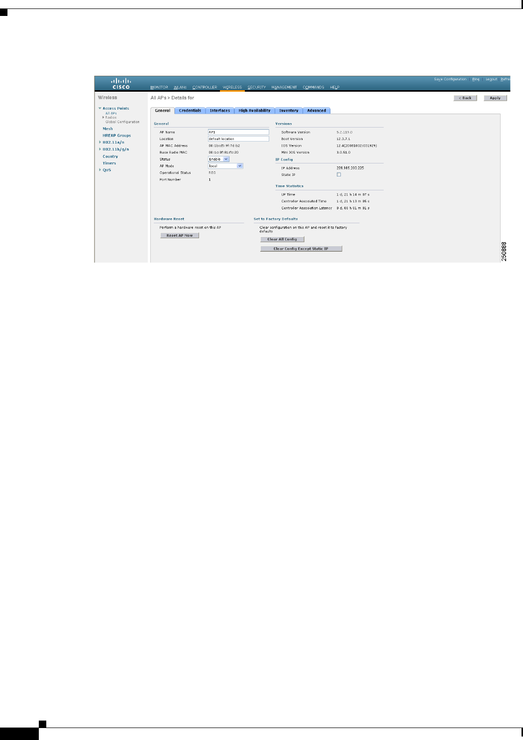
Step 1 Choose Wireless > Access Points > All APs to open the All APs page.
Step 2 Click the name of the access point that you want to configure as the sniffer. The All APs > Details for
page appears (see Figure D-14).
D-46
Cisco Wireless LAN Controller Configuration Guide
OL-21524-02
Appendix D Troubleshooting
Configuring Wireless Sniffing
Figure D-14 All APs > Details for Page
Step 3 From the AP Mode drop-down list, choose Sniffer.
Step 4 Click Apply to commit your changes.
Step 5 Click OK when warned that the access point will be rebooted.
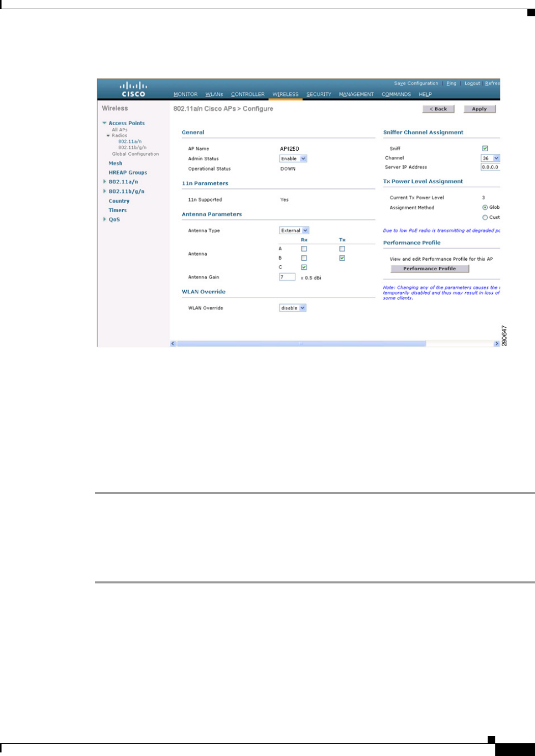
Step 6 Choose Wireless > Access Points > Radios > 802.11a/n (or 802.11b/g/n) to open the 802.11a/n (or
802.11b/g/n) Radios page.
Step 7 Hover your cursor over the blue drop-down arrow for the desired access point and choose Configure.
The 802.11a/n (or 802.11b/g/n) Cisco APs > Configure page appears (see Figure D-15).
D-47
Cisco Wireless LAN Controller Configuration Guide
OL-21524-02
Appendix D Troubleshooting
Configuring Wireless Sniffing
Figure D-15 802.11a/n Cisco APs > Configure Page
Step 8 Unselect the Sniff check box to enable sniffing on this access point, or leave it unselected to disable
sniffing. The default value is unchecked.
Step 9 If you enabled sniffing in Step 8, follow these steps:
a. From the Channel drop-down list, choose the channel on which the access point sniffs for packets.
b. In the Server IP Address text box, enter the IP address of the remote machine running Omnipeek,
Airopeek, AirMagnet, or Wireshark.
Step 10 Click Apply to commit your changes.
Step 11 Click Save Configuration to save your changes.
Using the CLI to Configure Sniffing on an Access Point
To configure sniffing on an access point using the controller CLI, follow these steps:
Step 1 To configure the access point as a sniffer, enter this command:
config ap mode sniffer Cisco_AP
where Cisco_AP is the access point configured as the sniffer.
Step 2 When warned that the access point will be rebooted and asked if you want to continue, enter Y. The
access point reboots in sniffer mode.
Step 3 To enable sniffing on the access point, enter this command:
config ap sniff {802.11a | 802.11b} enable channel server_IP_address Cisco_AP

D-48
Cisco Wireless LAN Controller Configuration Guide
OL-21524-02
Appendix D Troubleshooting
Troubleshooting Access Points Using Telnet or SSH
where
–
channel is the radio channel on which the access point sniffs for packets. The default values are
36 (802.11a/n) and 1 (802.11b/g/n).
–
server_IP_address is the IP address of the remote machine running Omnipeek, Airopeek,
AirMagnet, or Wireshark.
–
Cisco_AP is the access point configured as the sniffer.
Note To disable sniffing on the access point, enter the config ap sniff {802.11a | 802.11b} disable
Cisco_AP command.
Step 4 To save your changes, enter this command:
save config
Step 5 To view the sniffer configuration settings for an access point, enter this command:
show ap config {802.11a | 802.11b} Cisco_AP
Information similar to the following appears:
Cisco AP Identifier................................ 17
Cisco AP Name.......................................... AP1131:46f2.98ac
...
AP Mode ........................................... Sniffer
Public Safety ..................................... Global: Disabled, Local: Disabled
Sniffing .............................................. No
...
Troubleshooting Access Points Using Telnet or SSH
The controller supports the use of the Telnet and Secure Shell (SSH) protocols to troubleshoot
lightweight access points. Using these protocols makes debugging easier, especially when the access
point is unable to connect to the controller.
• To avoid potential conflicts and security threats to the network, the following commands are
unavailable while a Telnet or SSH session is enabled: config terminal, telnet, ssh, rsh, ping,
traceroute, clear, clock, crypto, delete, fsck, lwapp, mkdir, radius, release, reload, rename,
renew, rmdir, save, set, test, upgrade.
• Commands available during a Telnet or SSH session include debug, disable, enable, help, led,
login, logout, more, no debug, show, systat, undebug, where.
You can configure Telnet or SSH by using the controller CLI in software release 5.0 or later releases or
using the controller GUI in software release 6.0 or later releases.
Note See the “Configuring Telnet and SSH Sessions” section on page 2-34 for instructions on configuring
Telnet or SSH sessions on the controller.
D-49
Cisco Wireless LAN Controller Configuration Guide
OL-21524-02
Appendix D Troubleshooting
Troubleshooting Access Points Using Telnet or SSH
Using the GUI to Troubleshoot Access Points Using Telnet or SSH
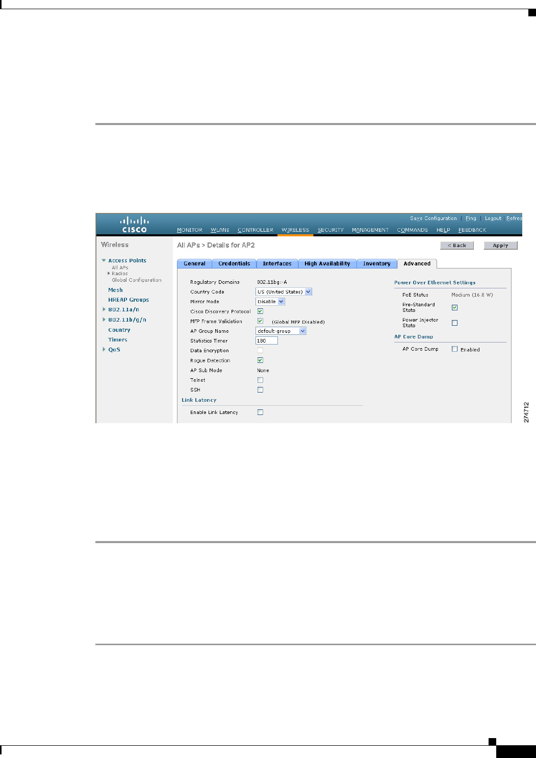
To enable Telnet or SSH access (or both) on lightweight access points using the controller GUI, follow
these steps:
Step 1 Choose Wireless > Access Points > All APs to open the All APs page.
Step 2 Click the name of the access point for which you want to enable Telnet or SSH.
Step 3 Choose the Advanced tab to open the All APs > Details for (Advanced) page (see Figure D-16).
Figure D-16 All APs > Details for (Advanced) Page
Step 4 To enable Telnet connectivity on this access point, select the Telne t check box. The default value is
unchecked.
Step 5 To enable SSH connectivity on this access point, select the SSH check box. The default value is
unchecked.
Step 6 Click Apply to commit your changes.
Step 7 Click Save Configuration to save your changes.
Using the CLI to Troubleshoot Access Points Using Telnet or SSH
To enable Telnet or SSH access (or both) on lightweight access points using the controller CLI, follow
these steps:
Step 1 To enable Telnet or SSH connectivity on an access point, enter this command:
config ap {telnet | ssh} enable Cisco_AP
The default value is disabled.

D-50
Cisco Wireless LAN Controller Configuration Guide
OL-21524-02
Appendix D Troubleshooting
Debugging the Access Point Monitor Service
Note To disable Telnet or SSH connectivity on an access point, enter this command:
config ap {telnet | ssh} disable Cisco_AP
Step 2 To save your changes, enter this command:
save config
Step 3 To see whether Telnet or SSH is enabled on an access point, enter this command:
show ap config general Cisco_AP
Information similar to the following appears:
Cisco AP Identifier.............................. 5
Cisco AP Name.................................... AP33
Country code..................................... Multiple Countries:US,AE,AR,AT,AU,BH
Reg. Domain allowed by Country................... 802.11bg:-ABCENR 802.11a:-ABCEN
AP Country code.................................. US - United States
AP Regulatory Domain............................. 802.11bg:-A 802.11a:-A
Switch Port Number .............................. 2
MAC Address...................................... 00:19:2f:11:16:7a
IP Address Configuration......................... Static IP assigned
IP Address....................................... 10.22.8.133
IP NetMask....................................... 255.255.248.0
Gateway IP Addr.................................. 10.22.8.1
Domain...........................................
Name Server......................................
Telnet State..................................... Enabled
Ssh State........................................ Enabled
...
Debugging the Access Point Monitor Service
The controller sends access point status information to the Cisco 3300 Series Mobility Services Engine
(MSE) using the access point monitor service.
The MSE sends a service subscription and an access point monitor service request to get the status of all
access points currently known to the controller. When any change is made in the status of an access point,
a notification is sent to the MSE.
Using the CLI to Debug Access Point Monitor Service Issues
If you experience any problems with the access point monitor service, enter this command:
debug service ap-monitor {all | error | event | nmsp | packet} {enable | disable}
where
• all configures debugging of all access point status messages.
• error configures debugging of access point monitor error events.
• event configures debugging of access point monitor events.
• nmsp configures debugging of access point monitor NMSP events.
• packet configures debugging of access point monitor packets.
D-51
Cisco Wireless LAN Controller Configuration Guide
OL-21524-02
Appendix D Troubleshooting
Troubleshooting OfficeExtend Access Points
• enable enables the debub service ap-monitor mode.
• disable disables the debug service ap-monitor mode.
Troubleshooting OfficeExtend Access Points
This section provides troubleshooting information if you experience any problems with your
OfficeExtend access points.
Interpreting OfficeExtend LEDs
The LED patterns are different for 1130 series and 1140 series OfficeExtend access points. See the Cisco
OfficeExtend Access Point Quick Start Guide for a description of the LED patterns. You can find this
guide at this URL:
http://www.cisco.com/en/US/products/hw/wireless/index.html
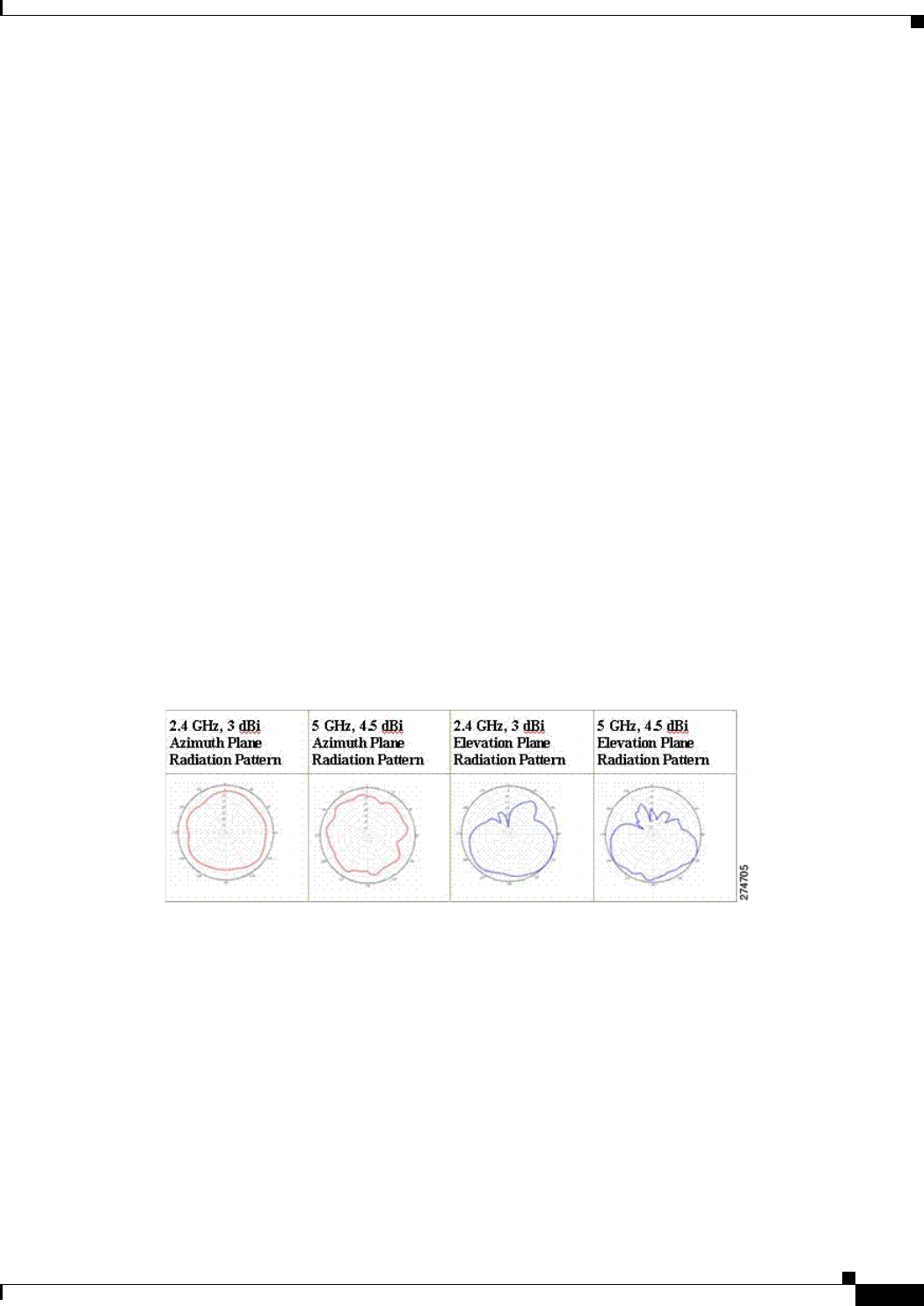
Positioning OfficeExtend Access Points for Optimal RF Coverage
When positioning your OfficeExtend access point, consider that its RF signals are emitted in a cone
shape spreading outward from the LED side of the access point (see Figure D-17). Be sure to mount the
access point so that air can flow behind the metal back plate and prevent the access point from
overheating.
Figure D-17 OfficeExtend Access Point Radiation Patterns
Troubleshooting Common Problems
Most of the problems experienced with OfficeExtend access points are one of the following:
• The access point cannot join the controller because of network or firewall issues.
Resolution: Follow the instructions in the “Viewing Access Point Join Information” section on
page 8-55 to view join statistics for the OfficeExtend access point, or find the access point’s public
IP address and perform pings of different packet sizes from inside the company.
• The access point joins but keeps dropping off. This behavior usually occurs because of network
problems or when the network address translation (NAT) or firewall ports close because of short
timeouts.

D-52
Cisco Wireless LAN Controller Configuration Guide
OL-21524-02
Appendix D Troubleshooting
Troubleshooting OfficeExtend Access Points
Resolution: Ask the teleworker for the LED status.
• Clients cannot associate because of NAT issues.
Resolution: Ask the teleworker to perform a speed test and a ping test. Some servers do not return
big packet pings.
• Clients keep dropping data. This behavior usually occurs because the home router closes the port
because of short timeouts.
Resolution: Perform client troubleshooting in WCS to determine if the problem is related to the
OfficeExtend access point or the client.
• The access point is not broadcasting the enterprise WLAN.
Resolution: Ask the teleworker to check the cables, power supply, and LED status. If you still
cannot identify the problem, ask the teleworker to try the following:
–
Connect to the home router directly and see if the PC is able to connect to an Internet website
such as http://www.cisco.com/. If the PC cannot connect to the Internet, check the router or
modem. If the PC can connect to the Internet, check the home router configuration to see if a
firewall or MAC-based filter is enabled that is blocking the access point from reaching the
Internet.
–
Log into the home router and check to see if the access point has obtained an IP address. If it
has, the access point’s LED normally blinks orange.
• The access point cannot join the controller, and you cannot identify the problem.
Resolution: A problem could exist with the home router. Ask the teleworker to check the router
manual and try the following:
–
Assign the access point a static IP address based on the access point’s MAC address.
–
Put the access point in a demilitarized zone (DMZ), which is a small network inserted as a
neutral zone between a company’s private network and the outside public network. It prevents
outside users from getting direct access to a server that has company data.
–
If problems still occur, contact your company’s IT department for assistance.
• The teleworker experiences problems while configuring a personal SSID on the access point.
Resolution: Clear the access point configuration and return it to factory default settings by clicking
Clear Config on the access point GUI or by entering the clear ap config Cisco_AP command and
then follow the steps in the “Configuring a Personal SSID on an OfficeExtend Access Point” section
on page 8-85 to try again. If problems still occur, contact your company’s IT department for
assistance.
• The home network needs to be rebooted.
Resolution: Ask the teleworker to follow these steps:
a. Leave all devices networked and connected, and then power down all the devices.
b. Turn on the cable or DSL modem, and then wait for 2 minutes. (Check the LED status.)
c. Turn on the home router, and then wait for 2 minutes. (Check the LED status.)
d. Turn on the access point, and then wait for 5 minutes. (Check the LED status.)
e. Turn on the client.

E-1
Cisco Wireless LAN Controller Configuration Guide
OL-21524-02
APPENDIX
E
Logical Connectivity Diagrams
This appendix provides logical connectivity diagrams for the controllers integrated into other Cisco
products, specifically the Catalyst 3750G Integrated Wireless LAN Controller Switch, the Cisco WiSM,
and the Cisco 28/37/38xx Series Integrated Services Router. These diagrams show the internal
connections between the switch or router and the controller. The software commands used for
communication between the devices are also provided. This appendix contains these sections:
• Cisco WiSM, page E-1
• Cisco 28/37/38xx Integrated Services Router, page E-3
• Catalyst 3750G Integrated Wireless LAN Controller Switch, page E-4
Cisco WiSM
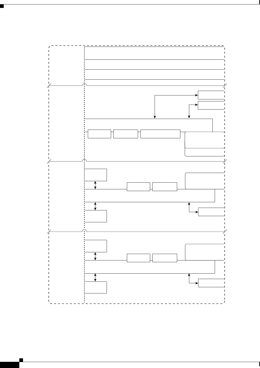
Figure E-1 shows the logical connectivity for the Cisco WiSM.
E-2
Cisco Wireless LAN Controller Configuration Guide
OL-21524-02
Appendix E Logical Connectivity Diagrams
Cisco WiSM
Figure E-1 Logical Connectivity Diagram for the Cisco WiSM
The commands used for communication between the Cisco WiSM, the Supervisor 720, and the 4404
controllers are documented in Configuring a Cisco Wireless Services Module and Wireless Control
System at this URL:
155912
Switch or Router Motherboard
Various Switch or Router Blades providing
100M/Gig/PoE/SFP Ports
Controller Motherboard
4 Gig E
Ports
Ethernet
Ethernet
Ethernet
Ethernet
RS-232 Serial
at 9600 baud
Supervisor 720
4404
Controller-A
4404
Controller-B
Hidden
Port 1
Port 2
Port 3
Port 4
Hidden
Port 5
Port 6
Port 7
Port 8
Hidden
Port 9
Hidden
Port 10
2 SFP Ports
Console
Console
RS-232 Serial
at 9600 baud
Console
RS-232 Serial
at 9600 baud
Memory Boot Flash
Memory Boot Flash
Flash File System Flash File System
on CF Card
Disk 0
Disk 1
Flash File System
on CF Card
Do not remove
Flash File System
on CF Card
Do not remove
Gig E
Service
Controller Motherboard
4 Gig E
Ports
Memory Boot Flash
Gig E
Service
Catalyst 6500 WiSM or Cisco 7600 Series Router WiSM
E-3
Cisco Wireless LAN Controller Configuration Guide
OL-21524-02
Appendix E Logical Connectivity Diagrams
Cisco 28/37/38xx Integrated Services Router
http://www.cisco.com/en/US/docs/wireless/technology/wism/technical/reference/appnote.html#wp394
98
Cisco 28/37/38xx Integrated Services Router
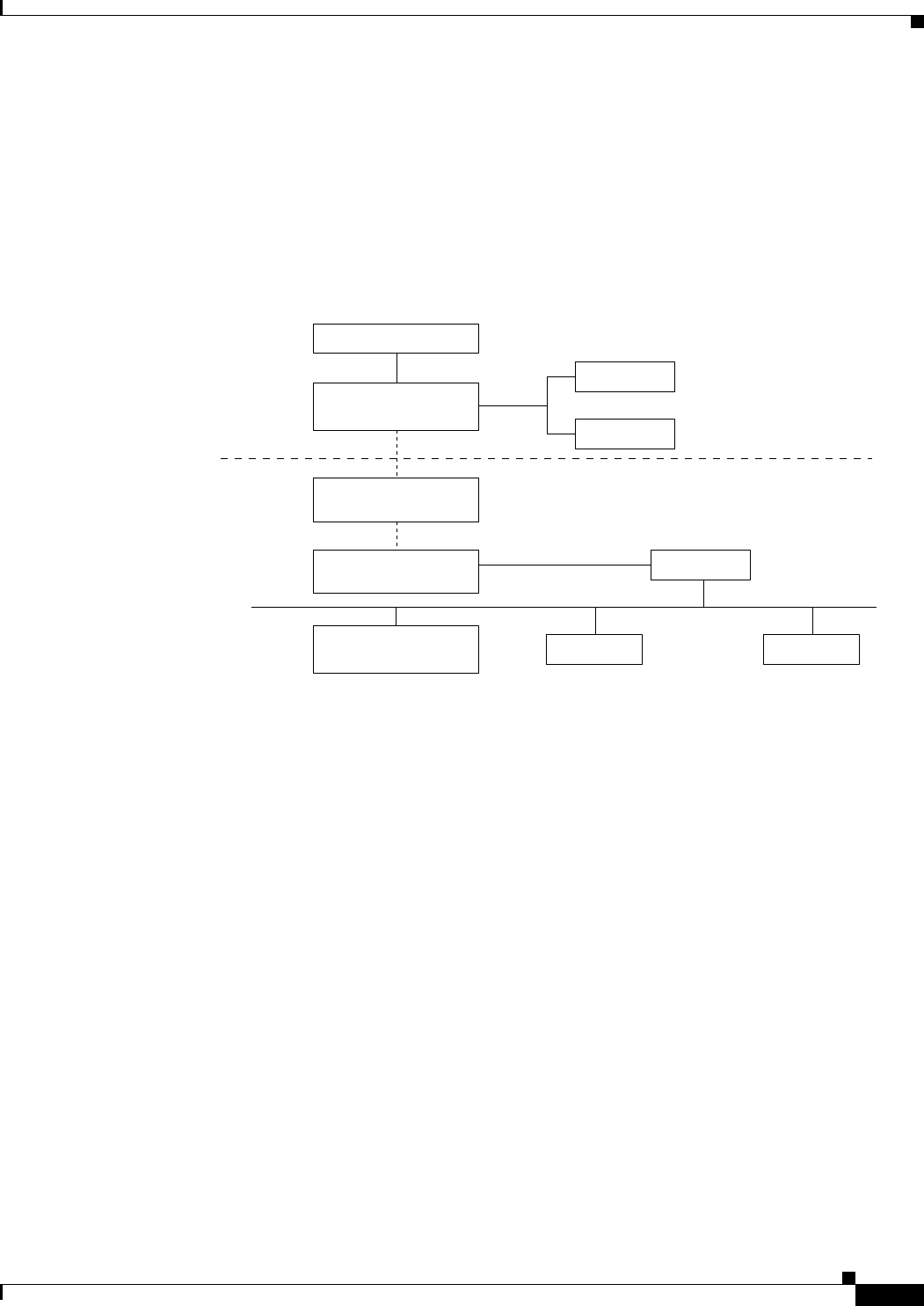
Figure E-2 shows the logical connectivity for the Cisco 28/37/38xx integrated services router.
Figure E-2 Logical Connectivity Diagram for the Cisco 28/37/38xx Integrated Services Router
These commands are used for communication between the 28/37/38xx Integrated Services Router and
the controller network module. They are initiated from the router. The commands vary depending on the
version of the network module.
These commands are used for communication between the router and Fast Ethernet versions of the
controller network module:
• interface wlan-controller slot/unit (and support for subinterfaces with dot1q encap)
• show interfaces wlan-controller slot/unit
• show controllers wlan-controller slot/unit
• test service-module wlan-controller slot/unit
• test HW-module wlan-controller slot/unit reset {enable | disable}
• service-module wlan-controller slot/port {reload | reset | session [clear] | shutdown | status}
These commands are used for communication between the router and Gigabit Ethernet versions of the
controller network module:
• interface integrated-service-engine slot/unit (and support for subinterfaces with dot1q encap)
• show interfaces integrated-service-engine slot/unit
• show controllers integrated-service-engine slot/unit
• test service-module integrated-service-engine slot/unit
• test HW-module integrated-service-engine slot/unit reset {enable | disable}
Console
28/37/38xx
Integrated
Services Router
Controller
Network Module
Router CPU
(Cisco IOS Software)
Memory
Flash
Internal Ethernet
Interface
Internal Ethernet
Interface 1 CPU
Compact Flash Memory StrataFlash
230621
E-4
Cisco Wireless LAN Controller Configuration Guide
OL-21524-02
Appendix E Logical Connectivity Diagrams
Catalyst 3750G Integrated Wireless LAN Controller Switch
• service-module integrated-service engine slot/port {reload | reset | session [clear] | shutdown |
status}
Note See the Cisco Wireless LAN Controller Network Module Feature Guide for more information. You can
find this document at this URL:
http://www.cisco.com/univercd/cc/td/doc/product/software/ios124/124newft/124limit/124x/124xa2/bo
xernm.htm#wp2033271
Catalyst 3750G Integrated Wireless LAN Controller Switch
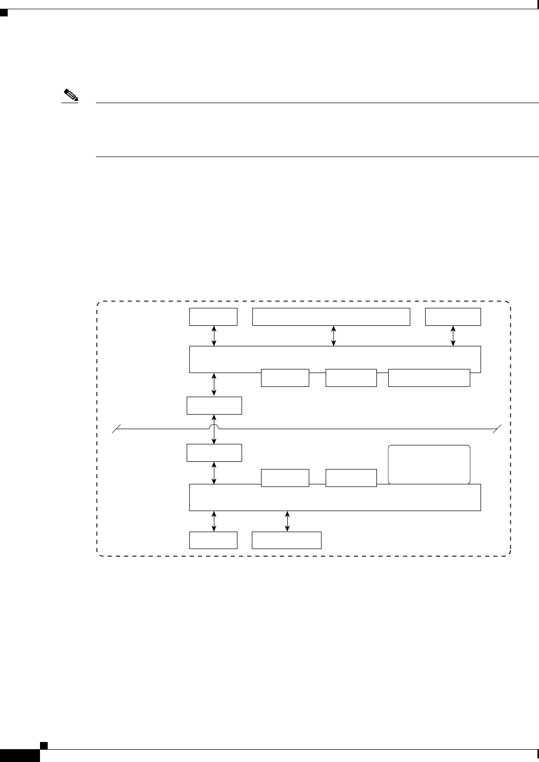
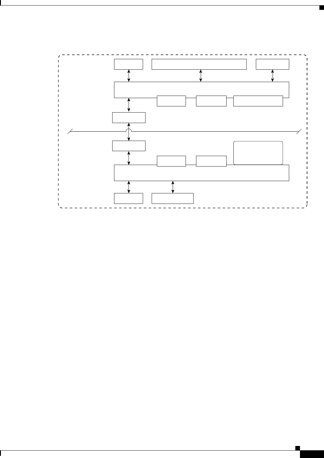
Figure E-3 shows the logical connectivity for the catalyst 3750G integrated wireless LAN.
Figure E-3 Logical Connectivity Diagram for the Catalyst 3750G Integrated Wireless LAN
Controller Switch
3750G Switch
4402
Controller
Hidden
G1/0/27
G1/0/28
155911
24 Gig PoE Ports
Switch Motherboard
Controller Motherboard
Console
Console Gig E Service
RS-232 Serial
at 9600 baud
Ethernet
2 SFP Ports
G1/0/1 through G1/0/24
RS-232 Serial
at 9600 baud
G1/0/25
G1/0/26
2 SFP Ports
Hidden
Port 1
Port 2
2 SFP Ports
Memory Boot Flash Flash File System
Memory Boot Flash
Flash File System
on CF Card
Do not remove
E-5
Cisco Wireless LAN Controller Configuration Guide
OL-21524-02
Appendix E Logical Connectivity Diagrams
Catalyst 3750G Integrated Wireless LAN Controller Switch
These commands are used for communication between the Catalyst 3750G switch and the 4402
controller.
Login Command
This command is used to initiate a telnet session from the switch to the controller:
session switch_number processor 1
Because there can be several switches in a stack, the switch_number parameter is used to indicate to
which controller in the stack this session should be directed. Once a session is established, the user
interacts with the controller CLI. Entering exit terminates the session and returns the user to the switch
CLI.
Show Commands
These commands are used to view the status of the internal controller. They are initiated from the switch.
• show platform wireless-controller switch_number summary
Information similar to the following appears:
Switch Status State
1 up operational
2 up operational
• show platform wireless-controller switch_number status
3750G Switch
4402
Controller
Hidden
G1/0/27
G1/0/28
155911
24 Gig PoE Ports
Switch Motherboard
Controller Motherboard
Console
Console Gig E Service
RS-232 Serial
at 9600 baud
Ethernet
2 SFP Ports
G1/0/1 through G1/0/24
RS-232 Serial
at 9600 baud
G1/0/25
G1/0/26
2 SFP Ports
Hidden
Port 1
Port 2
2 SFP Ports
Memory Boot Flash Flash File System
Memory Boot Flash
Flash File System
on CF Card
Do not remove

E-6
Cisco Wireless LAN Controller Configuration Guide
OL-21524-02
Appendix E Logical Connectivity Diagrams
Catalyst 3750G Integrated Wireless LAN Controller Switch
Information similar to the following appears:
Switch Service IP Management IP SW Version Status
------+---------------+---------------+---------------+-------
1 127.0.1.1 70.1.30.1 4.0.52.0 operational
2 127.0.1.2 70.1.31.1 4.0.45.0 operational
• show platform wireless-controller switch_number management-info
sw vlan ip gateway http https mac version
1 0 70.1.30.1/16 70.1.1.1 1 1 0016.9dca.d963 4.0.52.0
2 0 70.1.31.1/16 70.1.1.1 0 1 0016.9dca.dba3 4.0.45.0
Debug Commands
The Wireless Control Protocol (WCP) is an internal keep-alive protocol that runs between the switch and
the controller. It enables the switch to monitor the health of the controller and to report any problems. It
uses UDP and runs over the two internal Gigabit ports, but it creates an internal VLAN 4095 to separate
control traffic from data traffic. Every 20 seconds the switch sends a keep-alive message to the controller.
If the controller does not acknowledge 16 consecutive keep-alive messages, the switch declares the
controller dead and sends a reset signal to reboot the controller.
These commands are used to monitor the health of the internal controller.
This command is initiated from the controller.
• debug wcp ?
where ? is one of the following:
packet—Debugs WCP packets.
events—Debugs WCP events.
Information similar to the following appears:
Tue Feb 7 23:30:31 2006: Received WCP_MSG_TYPE_REQUEST
Tue Feb 7 23:30:31 2006: Received WCP_MSG_TYPE_REQUEST,of type WCP_TLV_KEEP_ALIVE
Tue Feb 7 23:30:31 2006: Sent WCP_MSG_TYPE_RESPONSE,of type WCP_TLV_KEEP_ALIVE
Tue Feb 7 23:30:51 2006: Received WCP_MSG_TYPE_REQUEST
Tue Feb 7 23:30:51 2006: Received WCP_MSG_TYPE_REQUEST,of type WCP_TLV_KEEP_ALIVE
Tue Feb 7 23:30:51 2006: Sent WCP_MSG_TYPE_RESPONSE,of type WCP_TLV_KEEP_ALIVE
Tue Feb 7 23:31:11 2006: Received WCP_MSG_TYPE_REQUEST
Tue Feb 7 23:31:11 2006: Received WCP_MSG_TYPE_REQUEST,of type WCP_TLV_KEEP_ALIVE
Tue Feb 7 23:31:11 2006: Sent WCP_MSG_TYPE_RESPONSE,of type WCP_TLV_KEEP_ALIVE
This command is initiated from the switch.
• debug platform wireless-controller switch_number ?
where ? is one of the following:
all—All
errors—Errors
packets—WCP packets
sm—State machine
wcp—WCP protocol

E-7
Cisco Wireless LAN Controller Configuration Guide
OL-21524-02
Appendix E Logical Connectivity Diagrams
Catalyst 3750G Integrated Wireless LAN Controller Switch
Reset Commands
These two commands (in this order) are used to reset the controller from the switch. They are not yet
available but will be supported in a future release.
• test wireless-controller stop switch_number
• test wireless-controller start switch_number
Note A direct console connection to the controller does not operate when hardware flow control is enabled on
the PC. However, the switch console port operates with hardware flow control enabled.

E-8
Cisco Wireless LAN Controller Configuration Guide
OL-21524-02
Appendix E Logical Connectivity Diagrams
Catalyst 3750G Integrated Wireless LAN Controller Switch

IN-1
Cisco Wireless LAN Controller Configuration Guide
OL-21524-02
INDEX
Symbols
. D-5
Numerics
11n Mode parameter 4-34
1250 series access points
and PoE Status field 8-130
operating modes when using PoE 8-128
transmit power settings when using PoE 8-129
3DES IPSec data encryption 6-9
7920 AP CAC parameter 7-41
7920 Client CAC parameter 7-41
7920 support mode
configuring 7-39
described 7-39
7921 support mode 7-40
802.11a (or 802.11b) > Client Roaming page 4-64
802.11a (or 802.11b) > Voice Parameters page 4-78, 4-80,
4-85
802.11a (or 802.11b/g) > EDCA Parameters page 4-94
802.11a (or 802.11b/g) Global Parameters > Auto RF
page 13-9
802.11a (or 802.11b/g) Global Parameters page 4-29, 13-49
802.11a (or 802.11b/g) Network Status parameter 4-30,
4-38
802.11a/n (4.9 GHz) > Configure page 9-128
802.11a/n (or 802.11b/g/n) Cisco APs > Configure
page 13-33
802.11a/n (or 802.11b/g/n) Radios page 4-83, 13-32, 13-45
802.11a/n Cisco APs > Configure page 9-19, 13-46
802.11a/n Radios page (from Monitor Menu) 8-31
802.11a/n Radios page (from Wireless Menu) 8-31
802.11a > RRM > Coverage page 13-21
802.11a > RRM > DCA page 13-17
802.11a > RRM > Dynamic Channel Assignment (DCA)
page 13-17
802.11a > RRM > General page 13-23
802.11a Global Parameters page 13-44
802.11b/g/n Cisco APs > Configure page 8-117, D-47
802.11 bands
configuring using the CLI 4-31 to 4-33
configuring using the GUI 4-29 to 4-31
802.11g Support parameter 4-30
802.11h, described 4-38
802.11h Global Parameters page 4-38
802.11h parameters, configuring
using the CLI 4-39
using the GUI 4-38 to 4-39
802.11n
clients 8-133
configuring
using the CLI 4-35 to 4-37
using the GUI 4-33 to 4-35
devices 4-33
802.11n (2.4 GHz) High Throughput page 4-34
802.1Q VLAN trunk port 3-5
802.1X
configuring 7-24
described 7-25
dynamic key settings 7-24
802.1X+CCKM
configuring 7-27
described 7-26
802.1X authentication for access points
configuring

Index
IN-2
Cisco Wireless LAN Controller Configuration Guide
OL-21524-02
the switch 8-41
using the CLI 8-39 to 8-41
using the GUI 8-38 to 8-39
described 8-37
802.1x Authentication parameter 8-38
802.3 bridging
configuring using the CLI 4-56
configuring using the GUI 4-55 to 4-56
802.3 Bridging parameter 4-56
802.3 frames 4-55
802.3X flow control, enabling 4-54
A
AAA override
configuring
using the CLI 6-88
using the GUI 6-88
described 6-86
AC adapter warning for Japan B-2
Access Control List Name parameter 6-63
access control lists (ACLs)
applying to an interface
using the CLI 6-71
applying to a WLAN
using the CLI 6-72
using the GUI 6-68 to 6-69
applying to the controller CPU
using the CLI 6-72
using the GUI 6-67 to 6-68
configuring
using the CLI 6-70 to 6-71
using the GUI 6-62 to 6-66
counters
configuring using the CLI 6-70
configuring using the GUI 6-63
described 6-61
identity networking 6-84
rules 6-62, 6-64, 6-71
using with the debug facility D-40 to D-41
Access Control Lists > Edit page 6-65
Access Control Lists > New page 6-63
Access Control Lists > Rules > New page 6-63
Access Control Lists page 6-62
Access Mode parameter 4-44, 4-46
access point
assisted roaming, described 9-92
access point core dumps, uploading
using the CLI 8-63
using the GUI 8-63
access point count, approved tiers for 5500 series
controllers 4-4
access point event logs, viewing D-15
access point groups
assigning access points to
using the CLI 7-61
using the GUI 7-60
creating
using the CLI 7-60 to 7-61
using the GUI 7-57 to 7-60
default group 7-57
described 7-55
illustrated 7-56
removing
using the CLI 7-61
using the GUI 7-58
viewing 7-61 to 7-62
access point monitor service, debugging D-50
access point radios, searching for 8-31 to 8-32
access points
20-MHz channelization 13-33
40-MHz channelization 13-34
adding MAC address to controller filter list
using the GUI ?? to 9-25
assisted roaming 4-63
authorization list 8-51
authorizing
using LSCs 8-46 to 8-50

Index
IN-3
Cisco Wireless LAN Controller Configuration Guide
OL-21524-02
using MICs 8-46
using SSCs 8-45
using the CLI 8-51
using the GUI 8-50
configuring hybrid REAP using the CLI 15-16 to 15-17
converting to mesh access points 9-124
embedded 8-41
guidelines for operating in Japan B-1
LEDs
configuring 8-132
interpreting D-2
migrating from the -J regulatory domain to the -U
regulatory domain 8-111 to 8-114
number supported per controller 3-5
priming 8-8
regulatory information ?? to B-2
searching for 8-10 to 8-12
supported for use with hybrid REAP 15-1
supporting oversized images 8-68 to 8-69
troubleshooting
the join process 8-53 to 8-60
using Telnet or SSH D-48 to D-50
VCI strings 8-52
verifying that they join the controller 8-9
viewing join information
using the CLI 8-58 to 8-60
using the GUI 8-55 to 8-58
viewing multicast client table 4-62
Accounting Server parameters 7-67
accounting servers, disabling per WLAN 7-66
ACL. See access control lists (ACLs)
ACL Name parameter 6-67, 6-68
ACS server configuration page 7-64
Action parameter 6-65
active exploits 6-133
Add AAA Client page (on CiscoSecure ACS) 6-4, 6-21
Add AP button 15-22
Add New Rule button 6-63
Add Web Server button 11-19
AdHoc Rogue AP parameter 6-94
administrator access 4-41
administrator usernames and passwords, configuring 4-41
Admin Status parameter 3-25, 3-26
Admission Control (ACM) parameter 4-78, 4-80
AES CBS IPSec data encryption 6-10
AES-CCMP 7-25
AES parameter 7-27
Aggregated MAC Protocol Data Unit (A-MPDU) 4-36
Aggregated MAC Service Data Unit (A-MSDU) 4-36
aggregation method, specifying 4-35
AirMagnet Enterprise Analyzer D-44
Aironet IE parameter 7-29, 7-53
Aironet IEs
configuring using the CLI 7-55
configuring using the GUI 7-53
Airopeek D-44
Alarm Trigger Threshold parameter 13-42
All APs > Access Point Name > Link Details > Neighbor
Name page 9-122
All APs > Access Point Name > Mesh Neighbor Stats
page 9-123
All APs > Access Point Name > Neighbor Info page 9-122
All APs > Access Point Name > Statistics page 9-117
All APs > Access Point Name > VLAN Mappings
page 15-15
All APs > Details (Advanced) page
configuring CDP 4-101
All APs > Details for (Advanced) page 8-4, 8-63, D-49
configuring country codes 8-108
configuring link latency 8-125
configuring PoE 8-130
All APs > Details for (Credentials) page 8-34, 8-38, 8-82
All APs > Details for (General) page 8-67, 8-80, 15-14
All APs > Details for (High Availability) page 8-80, 8-98,
8-102
All APs > Details for (H-REAP) page 8-81, 15-14
All APs > Details for (Inventory) page 8-121
All APs > Details for page D-46, D-51
All APs > Details page 9-26, 9-54, 9-79, 13-41

Index
IN-4
Cisco Wireless LAN Controller Configuration Guide
OL-21524-02
All APs page 8-10, 9-116, 9-121, 13-41, 15-14
Allow AAA Override parameter 6-88
AnchorTime parameter 9-70, 13-18
anonymous local authentication bind method 6-38, 6-40
Anonymous Provision parameter 6-48
Antenna Gain parameter 13-35
Antenna parameter 13-35
Antenna Type parameter 13-35
AP > Clients > Traffic Stream Metrics page 4-84
AP > Clients page 4-84
AP801 access point
described 8-41
using with a controller 8-41
AP Authentication Policy page 6-74, 13-42
AP Core Dump parameter 8-63
ap-count evaluation licenses, activating
using the CLI 4-19 to 4-20
using the GUI 4-17 to 4-19
AP Ethernet MAC Addresses parameter 8-48
AP Failover Priority parameter 8-102
AP Group Name parameter 7-58
AP Groups > Edit (APs) page 7-60
AP Groups > Edit (General) page 7-59
AP Groups > Edit (WLANs) page 7-59, 7-73
AP Groups page 7-57, 7-72
AP image download 8-27
AP Join Stats Detail page 8-58
AP Join Stats page 8-56
AP local authentication
Using GUI 15-18
AP Local Authentication on a WLAN
Using the CLI 15-18
AP-manager interface
and dynamic interfaces 3-9
configuring
using the CLI 3-16
using the GUI 3-11 to 3-14
creating multiple interfaces
using the CLI 3-47
using the GUI 3-45 to 3-46
described 3-7
illustration
of four AP-manager interfaces 3-45
of three AP-manager interfaces 3-44
of two AP-manager interfaces 3-43
using multiple 3-42 to 3-47
AP Mode parameter 8-80, 13-41, 15-14, D-46
AP Name parameter 7-60
AP Policies page 8-51
AP Primary Discovery Timeout parameter 8-97, 9-30
ASLEAP detection 6-133
Assignment Method parameter 13-33, 13-36
asymmetric tunneling
described 14-26
illustrated 14-27
authenticated local authentication bind method 6-38, 6-40
Authentication Protocol parameter 4-46
Auth Key Mgmt parameter 7-27
Authority ID Information parameter 6-48, 15-24, 15-26
Authority ID parameter 6-48, 15-24
Authorize LSC APs against auth-list parameter 8-51
Authorize MIC APs against auth-list or AAA
parameter 8-51
authorizing access points
using the CLI 8-51
using the GUI 8-50
auto-anchor mobility
configuring
using the GUI 14-22 to 14-24
guidelines 14-22
overview 14-21 to 14-22
auto-immune feature 6-114
AutoInstall
described 2-26, 2-29
example operation 2-29
obtaining
DHCP addresses for interfaces 2-26
TFTP server information 2-26

Index
IN-5
Cisco Wireless LAN Controller Configuration Guide
OL-21524-02
overview 2-26
selecting configuration file 2-28
using 2-26
Average Data Rate parameter 4-69, 4-73
Average Real-Time Rate parameter 4-69, 4-73
Avoid Cisco AP Load parameter 9-70, 13-18
Avoid Foreign AP Interference parameter 9-70, 13-18, 14-19
Avoid Non-802.11a (802.11b) Noise parameter 9-71, 13-18
B
Backhaul Client Access parameter 9-37, 9-128
backup controllers
configuring
using the CLI 8-99 to 8-100, 9-31 to 9-33
using the GUI 8-96 to 8-98, 9-29 to 9-31
described 8-95, 9-28
Back-up Primary Controller IP Address parameter 8-97,
9-30
Back-up Primary Controller Name field 8-97, 9-30
Back-up Secondary Controller IP Address
parameter 8-98, 9-30
Back-up Secondary Controller Name parameter 8-98, 9-30
bandwidth-based CAC
described 4-75
enabling
using the CLI 4-87
using the GUI 4-78
for mesh networks 9-94
Base MAC Address parameter 3-32
Beacon Period parameter 4-30
beamforming
configuring
using the CLI ?? to 9-20, 13-46 to 13-47
using the GUI ?? to 9-19, 13-44 to 13-46
described 13-43
guidelines 13-44
Beamforming parameter 13-45, 13-46
Bind Password parameter 6-38
Bind Username parameter 6-38
bridge protocol data units (BPDUs) 3-28
bridging parameters
configuring using the GUI ?? to 9-80
browsers supported 2-17
Buffered Log Level parameter D-9
Burst Data Rate parameter 4-69, 4-73
Burst Real-Time Rate parameter 4-69, 4-73
C
CAC
configuring for 7920 phones 7-39
described 4-75
enabling
using the CLI 4-88
using the GUI 4-80
in mesh networks 9-94
viewing in mesh networks 9-102 to 9-103
viewing using the CLI 4-89
capacity adder license. See licenses
CAPWAP
and mesh access points 9-12
cascading 13-6
CA Server URL parameter 8-47
Catalyst 3750G Integrated Wireless LAN Controller
Switch
described 1-13
logical connectivity diagram and associated software
commands E-4 to E-7
ports 3-3, 3-5
CCKM
configuring 7-27
described 7-25
hybrid-REAP groups 15-20
with mobility 14-7
CCX
configuring Aironet IEs
using the CLI 7-55

Index
IN-6
Cisco Wireless LAN Controller Configuration Guide
OL-21524-02
using the GUI 7-53
described 7-52
link test 8-121
viewing a client’s version
using the CLI 7-55
using the GUI 7-53 to 7-55
CCX Layer 2 client roaming
configuring
using the CLI 4-66
using the GUI 4-64 to 4-66
debugging using the CLI 4-67
described 4-63 to 4-64
obtaining information using the CLI 4-66
CCX radio management
configuring
using the CLI 13-50
using the GUI 13-49 to 13-50
debugging using the CLI 13-52
features 13-48
hybrid-REAP considerations 13-48
obtaining information using the CLI 13-50 to 13-52
CCXv5 clients
enabling location presence 4-117
troubleshooting D-25 to D-39
CCXv5 Req button D-32
CCX Version parameter 7-54
CDP > AP Neighbors > Detail page 4-104
CDP > AP Neighbors page 4-104
CDP > Global Configuration page 4-100
CDP > Interface Neighbors > Detail page 4-102
CDP > Interface Neighbors page 4-102
CDP > Traffic Metrics page 4-105
CDP Advertisement Version parameter 4-100
CDP AP Neighbors page 4-103
CDP Protocol Status parameter 4-100
CDP State parameter 4-101
Certificate Authority (CA) certificates
downloading
using the CLI 10-23 to 10-25
using the GUI 10-22
overview 10-22
using with local EAP 6-43, 6-49
Certificate File Name parameter 11-8
Certificate File Path parameter 11-8
Certificate Issuer parameter 6-47
Certificate Password parameter 10-20, 11-8
Certificate Type parameter 8-51
Change Filter link 8-10, 8-32, 8-56
Change Rules Priority parameter 6-99
Channel Announcement parameter 4-38
Channel Assignment Leader parameter 9-71, 13-19
Channel Assignment Method parameter 9-70, 13-17
channel bonding in the 5-GHz band 13-34
Channel parameter 13-33, D-47
Channel Quiet Mode parameter 4-38
channels
statically assigning using the CLI 13-37
statically assigning using the GUI 13-32 to 13-36
Channel Scan Duration parameter 13-24
Channel Width Parameter 13-18
Channel Width parameter 9-71, 13-33
Check Against CA Certificates parameter 6-47
Check Certificate Date Validity parameter 6-47
chokepoints for RFID tag tracking 4-109
CIDS Sensor Add page 6-112
CIDS Sensors List page 6-112
CIDS Shun List page 6-116
ciphers
configuring 7-27, 7-28
described 7-26
Cisco 2100 Series Wireless LAN Controllers
AutoInstall interfaces 2-26
described 1-7
FCC statement B-3
features not supported 1-7
network connections 1-16
ports 3-2, 3-3
Cisco 2500 Series Controller 1-8

Index
IN-7
Cisco Wireless LAN Controller Configuration Guide
OL-21524-02
Cisco 2500 Series Controllers
License SKUs 4-4
Cisco 28/37/38xx Integrated Services Router
described 1-12
logical connectivity diagram and associated software
commands E-3
ports 3-3, 3-5, 4-123
using 4-123
versions 1-12
Cisco 3200 Series Mobile Access Router (MAR)
described 9-127
operating with mesh access points
using the CLI to configure 9-129
using the GUI to configure 9-128
Cisco 3300 Series Mobility Services Engine (MSE), using
with wIPS 6-128
Cisco 4400 Series Wireless LAN Controllers
AutoInstall interfaces 2-26
choosing between link aggregation and multiple
AP-manager interfaces 3-36 to 3-46
described 1-9
FCC statement B-3
models 3-4
network connections 1-17
ports 3-2, 3-3, 3-4
Cisco 5500 Series Wireless LAN Controllers
choosing between link aggregation and multiple
AP-manager interfaces 3-36 to 3-46
CPUs D-5
described 1-9
FCC statement B-3
features not supported 1-9
interface configuration example 3-48
licenses. See licenses
models 3-4
multiple AP-manager interfaces 3-47 to 3-48
network connections 1-17
ports 3-2, 3-4
using the USB console port 3-34 to 3-35
Cisco 7920 Wireless IP Phones 7-40
Cisco 7921 Wireless IP Phones 7-40
Cisco Adaptive Wireless Path Protocol (AWPP) 9-12
Cisco AV-pairs 7-62, 7-63, 7-64
Cisco Centralized Key Management (CCKM). See CCKM
Cisco Clean Access (CCA) 7-68
Cisco CleanAir 12-1
Cisco Client Extensions (CCX). See CCX
Cisco Discovery Protocol (CDP)
configuring
using the CLI 4-105 to 4-106
using the GUI 4-99 to 4-101
debugging using the CLI 4-108
described 4-96
enabling using the GUI 4-100 to 4-101
sample network 4-99
supported devices 4-97
viewing neighbors
using the CLI 4-106 to 4-107
using the GUI 4-101 to 4-105
viewing traffic information
using the CLI 4-107
using the GUI 4-105
Cisco Discovery Protocol parameter 4-101
Cisco License Manager (CLM)
and the controller license agent 4-26
using to register PAKs 4-6
Cisco Licensing website 4-21
Cisco Logo parameter 11-12
Cisco NAC Appliance 7-68
CiscoSecure Access Control Server (ACS) 6-4
Cisco Spectrum Intelligence 12-24
Cisco Unified Wireless Network (UWN) Solution
described 1-1 to 1-4
illustrated 1-2
Cisco Wireless Control System (WCS) 1-2
Cisco WiSM
configuring the Supervisor 720 4-121 to ??
described 1-10 to 1-12
guidelines 4-122

Index
IN-8
Cisco Wireless LAN Controller Configuration Guide
OL-21524-02
logical connectivity diagram and associated software
commands E-1 to E-3
ports 3-3, 3-4
SSC key-hash 8-44
CKIP
configuring
using the CLI 7-30
using the GUI 7-29 to 7-30
described 7-29
CleanAir Benefits 12-2
CleanAir guidelines 12-4
Clear Config button 8-87
Clear Filter link 7-8, 8-12, 8-32, 8-57
clearing the controller configuration 10-34
Clear Stats button 14-20
Clear Stats on All APs button 8-56
CLI
basic commands 2-25
enabling wireless connections 2-37
logging into 2-23 to 2-25
logging out 2-25
navigating 2-25
troubleshooting commands D-6 to D-7
using 2-22 to 2-25
Client Certificate Required parameter 6-47
client exclusion policies, configuring
using the CLI 6-81 to 6-82
using the GUI 6-80 to 6-81
Client Exclusion Policies page 6-80
ClientLink. See beamforming
client location, using WCS 1-7
client MFP 6-73
Client Protection parameter 6-77
client reporting
configuring using the CLI D-34 to D-37
configuring using the GUI D-31 to D-34
described D-26
Client Reporting page D-33
client roaming, configuring 4-62 to 4-67
clients
connecting to WLANs 15-18
viewing
using the CLI 8-137
using the GUI 8-133 to 8-137
viewing CCX version
using the CLI 7-55
using the GUI 7-53 to 7-55
Clients > AP > Traffic Stream Metrics page 4-83
Clients > Detail page
configuring client reporting D-32
viewing a client’s CCX version 7-54
viewing client details 8-92, 8-136
viewing the status of workgroup bridges 8-91
viewing voice and video settings 4-82
Clients page
performing a link test 8-123
viewing clients 8-133
viewing the status of workgroup bridges 8-91
viewing voice and video settings 4-81
Client Type parameter 8-92, 8-93
Commands > Reset to Factory Defaults page 4-124
comma-separated values (CSV) file, uploading 15-23
Community Name parameter 4-44
conditional web redirect 7-62
configuring
using the CLI 7-65
using the GUI 7-64 to 7-65
described 7-63
Conditional Web Redirect parameter 7-65
Configuration File Encryption parameter 10-30
configuration files
downloading
using the CLI 10-31 to 10-32
using the GUI 10-30 to 10-31
editing 10-33 to 10-34
uploading
using the CLI 10-29 to 10-30
configuration wizard

Index
IN-9
Cisco Wireless LAN Controller Configuration Guide
OL-21524-02
CLI version 2-13 to 2-16
described 2-1
GUI version 2-2 to 2-13
Configuration Wizard - 802.11 Configuration page 2-11
Configuration Wizard Completed page 2-13
Configuration Wizard - Management Interface
Configuration page 2-6
Configuration Wizard - Miscellaneous Configuration
page 2-7
Configuration Wizard - Service Interface Configuration
page 2-5
Configuration Wizard - Set Time page 2-12
Configuration Wizard - SNMP Summary page 2-4, 2-6
Configuration Wizard - System Information page 2-3
Configuration Wizard - Virtual Interface Configuration
page 2-8
Configure 12-1
Configure Dynamic Anchoring of Static IP Clients
Using the CLI 14-31
Configure option for RRM override 13-33
Configure RF Group
Using CLI 13-12
Configure RF Group Mode
Using GUI 13-11
Configuring a Spectrum Expert 12-23
Configuring Cisco CleanAir
Using the GUI 12-5
Configuring Cisco Cleanair
Using the CLI 12-8
Configuring Dynamic Anchoring of Static IP Clients
Using the GUI 14-31
Configuring Sniffing on an Access Point
Using the GUI D-45
Confirm Password parameter 15-12
Console Log Level parameter D-9
console port
connecting 2-1 to 2-2
Control and Provisioning of Wireless Access Points
protocol (CAPWAP) 1-5
debugging 8-7
described 8-2
guidelines 8-2
viewing MTU information 8-6
controller failure detection time, reducing 8-95
controller network module
baud rate 3-3
versions 3-5
controllers
configuration
clearing 10-34
erasing 10-34
saving 10-33
connections 1-13
discovery process 8-7
guidelines for operating in Japan B-1 to B-2
multiple-controller deployment 1-3 to 1-4
overview 1-6 to 1-7
platforms 1-7 to 1-13
resetting factory default settings
using the GUI 4-124
single-controller deployment 1-2 to 1-3
synchronizing with location appliance 4-114
types of memory 1-15
upgrading software
using the CLI 10-8 to 10-10
using the GUI 10-5 to 10-7
Controller Spanning Tree Configuration page 3-31
Controller Time Source Valid parameter 6-77
Control Path parameter 14-23
core dump files
described D-18
uploading automatically to an FTP server
using the CLI D-19
using the GUI D-18
uploading from a 5500 series controller to a TFTP or
FTP server D-20
Core Dump page D-18
Country Code parameter 8-108
country codes

Index
IN-10
Cisco Wireless LAN Controller Configuration Guide
OL-21524-02
configuring
using the CLI 8-109 to 8-111
using the GUI 8-107 to 8-108
described 8-106
Japanese 8-112
viewing using the CLI 8-110
Country page 8-107
Coverage Exception Level per AP parameter 13-21
coverage hole detection
configuring per controller
using the CLI 13-27
using the GUI 13-20 to 13-22
disabling on a WLAN
described 7-67
using the CLI 7-68
using the GUI 7-67 to 7-68
coverage hole detection and correction 13-4
Coverage Hole Detection Enabled parameter 7-67
CPU Access Control Lists page 6-68
CPUs, 5500 series controllers D-5
crash files
uploading
using the CLI D-17
using the GUI D-16 to D-17
create 3-50
create interface group
using GUI 3-50
Create Interface Groups
using CLI 3-51
Creating Interface Groups
CLI 3-51
GUI 3-50
Current Channel parameter 13-36
Custom Signatures page 6-121
D
data encryption
and OfficeExtend access points 8-84
configuring
using the CLI 8-5 to 8-6
using the GUI 8-4 to 8-5
for OfficeExtend access points 8-82
Data Encryption parameter 8-5, 8-82
Datagram Transport Layer Security 8-26
Data Path parameter 14-23
Data Rates parameter 4-31
date
configuring manually 2-31
configuring through NTP server 2-29
setting
using the CLI 2-32
DCA Channel Sensitivity parameter 9-71, 13-18
DCA Channels parameter 9-71, 13-19
debug commands, sending 8-60
debug facility
configuring D-41 to D-44
described D-40 to D-41
default enable password 8-33
default-group access point group 7-57
Default Mobility Group parameter 14-12
Default Routers parameter 7-15
Delivery Traffic Indication Map (DTIM). See DTIM
period
Deny Counters parameter 6-65
Description parameter 6-34, 9-25, 15-12
Designated Root parameter 3-32
DES IPSec data encryption 6-9
Destination parameter 6-64
Destination Port parameter 6-65
Detect and Report Ad-Hoc Networks parameter 6-93
device certificates
downloading
using the CLI 10-21
using the GUI 10-19 to 10-20
overview 10-19
using with local EAP 6-43, 6-49
DHCP

Index
IN-11
Cisco Wireless LAN Controller Configuration Guide
OL-21524-02
configuring using the CLI 7-13
configuring using the GUI 7-12
debugging 7-13
DHCP Addr. Assignment Required parameter 7-12
DHCP Allocated Lease page 7-16
DHCP option 43, in controller discovery process 8-8
DHCP option 82
configuring
using the CLI 6-61
using the GUI 6-60
described 6-59
example 6-59
DHCP Option 82 Remote ID Field Format parameter 6-60
DHCP Parameters page 4-40, 4-41, 6-60
DHCP proxy
configuring
using the CLI 4-41
using the GUI 4-39 to 4-40, ?? to 4-41, ?? to 4-94
described 4-39
DHCP Scope > Edit page 7-15
DHCP scopes
configuring
using the CLI 7-16 to 7-17
using the GUI 7-14 to 7-15
described 7-14
DHCP Scopes page 7-14
DHCP server discovery 8-8
DHCP Server IP Addr parameter 7-12
DHCP Server Override parameter 7-12
DHCP servers
external 7-10 to 7-12
internal 7-10
DHCP Timeout
configurie using GUI 4-41
diagnostic channel
configuring
using the CLI D-27 to D-31
using the GUI D-26 to D-27
described D-25
Diagnostic Channel parameter D-27
directed roam request 4-64
Direction parameter 6-65
disabled clients, configuring a timeout 7-18
discovery request timer, configuring 8-99, 9-31
distribution system ports 3-3 to 3-5
Diversity parameter 13-35
DNS Domain Name parameter 7-15
DNS IP Address parameter 8-67
DNS Servers parameter 7-15
Domain Name parameter 8-67
domain name server (DNS) discovery 8-8
Download button
downloading a CA certificate 10-23
downloading a configuration file 10-31
downloading a customized web authentication login
page 11-22
downloading a device certificate 10-20
downloading a signature file 6-120
Download File to Controller page 10-17
downloading a customized web authentication login
page 11-21
downloading CA certificates 10-23
downloading configuration files 10-30
downloading device certificates 10-20
downloading IDS signatures 6-120
downloading login banner file 10-16
Download SSL Certificate parameter 11-7
DSCP parameter 6-65
DTIM period, configuring for MAC filtering 7-19
DTLS 4-2, 8-26
DTLS data encryption. See data encryption
DTPC Support parameter 4-30
Dynamic Anchoring for Clients with Static IP Addresses
Configuring 14-30
dynamic AP management
for dynamic interface 3-21
for the management interface 3-15
Dynamic AP Management parameter 3-9

Index
IN-12
Cisco Wireless LAN Controller Configuration Guide
OL-21524-02
for dynamic interface 3-20
for management interface 3-13
dynamic AP-manager interface 3-10
dynamic channel assignment (DCA)
20-MHz channelization 13-4, 13-19
40-MHz channelization 13-4, 13-19
configuring
using the CLI 13-25 to 13-27
using the GUI 9-69 to 9-72, 13-16 to 13-20
described 13-3
sensitivity thresholds 9-71
dynamic frequency selection 8-115 to 8-116
dynamic interface
configuring
using the CLI 3-21 to 3-22
using the GUI 3-18 to 3-21
described 3-9
dynamic interface example 3-48
dynamic transmit power control, configuring 4-30
dynamic WEP, configuring 7-24
Dynamic WEP Key Index parameter 6-45
E
EAP-FAST Method Parameters page 6-48
EAP-FAST parameter 6-46
EAPOL-Key Max Retries parameter 6-45
EAPOL-Key Timeout parameter 6-45
EAP Profile Name parameter 6-49
EAP-TLS parameter 6-46
EDCA Profile parameter 4-95
Edit QoS Profile page 4-68
Edit QoS Role Data Rates page 4-72
Egress Interface parameter 11-30
Email Input parameter 11-31
Enable AP Local Authentication parameter 15-23
Enable Authentication for Listener parameter 4-27
Enable Check for All Standard and Custom Signatures
parameter 6-122
Enable Controller Management to be accessible from
Wireless Clients parameter 2-37, 6-58
Enable Counters parameter 6-63
Enable Coverage Hole Detection parameter 13-21
Enable CPU ACL parameter 6-68
Enable Default Authentication parameter 4-27
Enable DHCP Proxy parameter 4-40
Enable Dynamic AP Management parameter 3-46
Enable EAP-FAST Authentication parameter 15-24
Enable IGMP Snooping parameter 4-59
Enable LEAP Authentication parameter 15-24
Enable Least Latency Controller Join parameter 8-82
Enable Link Latency parameter 8-82, 8-125, 8-126
Enable Listener parameter 4-27
Enable Low Latency MAC parameter 4-95
Enable LSC on Controller parameter 8-47
Enable NAT Address parameter 3-12
Enable Notification parameter 4-27
Enable OfficeExtend AP parameter 8-81
Enable passive client 7-77
Enable Password parameter 8-34
Enable Server Status parameter 6-38
Enable Tracking Optimization parameter 8-117
Encryption Key parameter 7-30
end user license agreement C-1 to C-4
end-user license agreement (EULA) 4-8
enhanced distributed channel access (EDCA) parameters
configuring using the CLI 4-95 to 4-96
enhanced neighbor list
described 4-63, 9-92
request (E2E) 4-63
Enter Saved Permission Ticket File Name parameter 4-23
EoIP port 14-23, 14-29
epings 14-23, 14-29
erasing the controller configuration 10-34
error codes, for failed VoIP calls 7-45 to 7-47
Ethernet connection, using remotely 2-24 to 2-25
Ethernet Multicast Mode parameter 4-59
evaluation licenses

Index
IN-13
Cisco Wireless LAN Controller Configuration Guide
OL-21524-02
installed on 5500 series controllers 4-3
event reporting for MFP 6-73
Excessive 802.11 Association Failures parameter 6-81
Excessive 802.11 Authentication Failures parameter 6-81
Excessive 802.1X Authentication Failures parameter 6-81
Excessive Web Authentication Failures parameter 6-81
Expedited Bandwidth parameter 4-78
expedited bandwidth requests
described 4-76
enabling
using the GUI 4-78
Expiration Timeout for Rogue AP and Rogue Client
Entries parameter 6-93
Extensible Authentication Protocol (EAP)
configuring 7-24
setting local timers 6-50 to 6-51
timeout and failure counters
per access point 6-53
per client 6-53
extension channel 13-36
F
factory default settings
resetting using the GUI 4-124
failover priority for access points
configuring
using the CLI 8-102
using the GUI 8-101 to 8-102
described 8-101
viewing using the CLI 8-103
failover protection 1-15
fake access point detection 6-133
Fallback Mode parameter 6-10
Fast Ethernet port 3-5
fast heartbeat timer
configuring
using the CLI 8-99
using the GUI 8-97
described 8-95
fast SSID changing
configuring using the CLI 4-54
configuring using the GUI 4-54
fault tolerance 15-5
FCC statement
2100 series controllers B-3
4400 series controllers B-3
5500 series controllers B-3
Federal Information Processing Standards (FIPS) 6-12
File Compression parameter 8-63
File Name to Save Credentials parameter 4-21
file transfers 1-14
File Type parameter
downloading a CA certificate 10-23
downloading a configuration file 10-30
downloading a customized web authentication login
page 11-21
downloading a device certificate 10-20
Login Banner 10-17
upgrading controller software 10-7
uploading a configuration file 10-28
uploading packet capture files D-22
uploading PACs 10-25
filter, using to view clients 8-134 to 8-135
Fingerprint parameter 6-113
flashing LEDs, configuring 8-132
Forward Delay parameter 3-32, 3-33
forwarding plane architecture 4-55
Fragmentation Threshold parameter 4-30
fragmented pings 3-6
Friendly Rogue > Create page 6-99
FTP server guidelines 10-2
G
General (controller) page
configuring 802.3 bridging 4-56
configuring an RF group 13-8

Index
IN-14
Cisco Wireless LAN Controller Configuration Guide
OL-21524-02
enabling link aggregation 3-40
General (security) page 6-31
General page 6-44
Generate Password parameter 11-4
Generate Rehost Ticket button 4-23
gigabit Ethernet port 3-5
Global AP Failover Priority parameter 8-102
Global Configuration page
configuring backup controllers 8-96, 9-29
configuring failover priority for access points 8-101
configuring global credentials for access points 8-34
global credentials for access points
configuring
using the CLI 8-35 to 8-36
using the GUI 8-33 to 8-35
described 8-33
overriding
using the CLI 8-35
using the GUI 8-34
Global multicast mode 7-76
Group Mode parameter 13-10, 14-18
Group Name parameter 14-13, 15-22
Group Setup page (on CiscoSecure ACS) 6-23
Guest LAN parameter 11-29
guest N+1 redundancy 14-21
guest user accounts
creating 11-1 to 11-6
creating as a lobby ambassador 11-3 to 11-5
viewing
using the CLI 11-6
using the GUI 11-5 to 11-6
Guest User parameter 6-33, 15-12
Guest User Role parameter 6-33, 15-12
guest WLAN, creating 11-5
GUI
browsers supported 2-17
enabling wireless connections 2-37
guidelines 2-17
logging into 2-17
logging out of 2-17
using 2-16
Guidelines and Limitations for Predownloading 10-12
GUI to configure passive client 7-75
H
Headline parameter 11-13
Hello Time parameter 3-32, 3-33
help, obtaining 2-17
hex2pcap sample output D-43
Holdtime parameter 3-32, 4-100
Honeypot access point detection 6-133
HREAP Groups > Edit (Local Authentication > Local
Users) page 15-23
HREAP Groups > Edit (Local Authentication > Protocols)
page 15-24
HREAP Groups > Edit page 15-22
HREAP Groups page 15-21
HREAP Group Support 15-21
H-REAP Local Switching parameter 15-10
H-REAP Mode AP Fast Heartbeat Timeout
parameter 8-97
H-REAP Mode AP Fast Heartbeat Timer State
parameter 8-97
H-REAP parameter 8-80
HTTP Access parameter 2-18
HTTP Configuration page 2-18
HTTPS Access parameter 2-19
hybrid REAP
access points supported 15-1
authentication process 15-2 to 15-5
bandwidth restriction 15-2, 15-3
configuring
access points using the CLI 15-16 to 15-17
access points using the GUI 15-13 to 15-16
controller using the GUI 15-8 to 15-12
guidelines 15-6
illustrated 15-2
number of access points supported 15-2

Index
IN-15
Cisco Wireless LAN Controller Configuration Guide
OL-21524-02
overview 15-1
hybrid-REAP
debugging 15-13, 15-17
hybrid-REAP groups
backup RADIUS server 15-20
CCKM 15-20
configuring
using the CLI 15-25
using the GUI 15-21 to 15-25
described 15-19
example 15-19
local authentication 15-20
Hybrid-REAP Groups and OKC 15-20
Hysteresis parameter 4-65
I
identity networking
configuring 6-82 to 6-86
overview 6-82 to 6-83
RADIUS attributes 6-83 to 6-86
Identity Request Max Retries parameter 6-45
Identity Request Timeout parameter 6-45
IDS 6-112
IDS sensors
configuring
using the CLI 6-114 to 6-115
using the GUI 6-112 to 6-114
described 6-112
IDS signature events
viewing using the CLI 6-126 to 6-128
viewing using the GUI 6-123 to 6-124
IDS signatures
configuring
using the CLI 6-124 to 6-126
using the GUI 6-119 to 6-123
described 6-117
frequency 6-123
MAC frequency 6-123, 6-125
measurement interval 6-122
pattern 6-122
quiet time 6-123, 6-125
tracking method 6-122
uploading or downloading using the
GUI 6-119 to 6-120
viewing
using the CLI 6-126 to 6-128
using the GUI 6-123 to 6-124
IGMP Snooping 7-77
IGMP Timeout parameter 4-59
IKE Diffie Hellman Group parameter 6-10
IKE Phase 1 parameter 6-10
Image pre-download 8-27
Index parameter for IDS 6-113
indoor access points
converting to mesh access points 9-124
infrastructure MFP
components 6-73
described 6-72
Infrastructure Protection parameter 6-77
Infrastructure Validation parameter 6-77
Ingress Interface parameter 11-30
Injector Switch MAC Address parameter 8-130
inline power 8-128
Install License button 4-8
inter-controller roaming
described 4-62
example 14-2
Interface Groups 3-50
using GUI 3-50
Interface groups 3-50
Interface Name parameter 7-59, 7-70, 7-73, 9-25
Interface parameter 7-12
interfaces
and identity networking 6-84
assigning WLANs 7-18
configuring
using the CLI 3-14 to 3-17

Index
IN-16
Cisco Wireless LAN Controller Configuration Guide
OL-21524-02
using the GUI 3-11 to 3-14
overview 3-6 to 3-9
Interfaces > Edit page
applying an ACL to an interface 6-67
configuring dynamic interfaces 3-19
configuring NAC out-of-band integration 7-71
creating multiple AP-manager interfaces 3-45
Interfaces > New page 3-18, 3-45
Interfaces page 3-12
interference 13-3
Interferences 12-2
Interference threshold parameter 13-23
Internet Group Management Protocol (IGMP)
configuring
using the CLI 4-61
using the GUI 4-59
snooping 4-57
inter-release mobility 14-10
inter-subnet mobility 14-7
inter-subnet roaming
described 4-63
illustrated 14-3 to 14-4
Interval parameter 9-70, 13-18, 13-49
intra-controller roaming
described 4-62
illustrated 14-1
Inventory page 8-120
Invoke Channel Update Now button 9-70, 13-17
Invoke Power Update Now button 13-13
IP address-to-MAC address binding
configuring 4-67
described 4-67
IP Mask parameter 4-44
IPSec parameter 6-9
IP Theft or IP Reuse parameter 6-81
IPv6 bridging
configuring
using the CLI 7-52
using the GUI 7-51 to 7-52
described 7-49
guidelines 7-49
IPv6 bridging and IPv4 web authentication example 7-51
IPv6 Enable parameter 7-52
J
Japanese country codes 8-112
Japanese regulations for migrating access points from the
-J to the -U regulatory domain 8-111 to 8-114
K
Keep Alive Count parameter 14-22
Keep Alive Interval parameter 14-22
Key Encryption Key (KEK) parameter 6-8
Key Format parameter 7-30
Key Index parameter 7-30
key permutation
configuring 7-30, 7-31
described 7-29
Key Permutation parameter 7-30
Key Size parameter 7-30
Key Wrap Format parameter 6-8
Key Wrap parameter 6-8
L
LAG. See link aggregation (LAG)
LAG Mode on Next Reboot parameter 3-40
Last Auto Channel Assignment parameter 9-71, 13-19
Last Power Level Assignment parameter 13-14
Layer 1 security 6-2
Layer 2
operation 1-5
security
configuring 7-24 to 7-31
described 6-2
Layer 2 Security parameter 7-27, 7-30, 7-65

Index
IN-17
Cisco Wireless LAN Controller Configuration Guide
OL-21524-02
Layer 3
operation 1-5
security
configuring 7-32 to 7-34
described 6-2
Layer 3 Security parameter
for VPN passthrough 7-33, 7-36
for web authentication 7-34
for web redirect 7-65
for wired guest access 11-30
LDAP
choosing server priority order 6-38
configuring
using the CLI 6-40 to 6-41
using the GUI 6-36 to 6-39
LDAP server
assigning to WLANs 6-39
choosing local authentication bind method
using the CLI 6-40
using the GUI 6-38
LDAP Servers > New page 6-37
LDAP Servers page 6-37
LDAP Servers parameter 6-49
LEAP parameter 6-46
Learn Client IP Address parameter 15-11
Lease Time parameter 7-15
LEDs
configuring 8-132
interpreting D-1
license agent
configuring
using the CLI 4-28 to 4-29
using the GUI 4-26 to 4-28
described 4-26
License Agent Configuration page 4-27
license agreement C-1 to C-4
License Commands (Rehost) page 4-21
License Commands page 4-7
License Detail page 4-10, 4-18
license level, changing
using the CLI 4-16
using the GUI 4-15
License Level page 4-14
licenses
activating ap-count evaluation licenses
using the CLI 4-19 to 4-20
using the GUI 4-17 to 4-19
choosing feature set
using the CLI 4-16
using the GUI 4-14 to 4-16
installing
using the CLI 4-8 to 4-9
using the GUI 4-7 to 4-8
obtaining 4-3 to 4-7
rehosting
described 4-20
using the CLI 4-23 to 4-25
using the GUI 4-21 to 4-23
removing
using the CLI 4-8
using the GUI 4-10
required for OfficeExtend access points 8-80
saving
using the CLI 4-9
using the GUI 4-8
SKUs 4-5, 4-6
transferring to a replacement controller after an
RMA 4-25 to 4-26
viewing
using the CLI 4-11 to 4-14
using the GUI 4-9 to 4-11
Licenses page 4-9, 4-15, 4-17
licensing portal, using to register PAKs 4-6
Lifetime parameter 6-33, 11-4, 15-12
Lightweight Access Point Protocol (LWAPP) 1-5, 8-2
lightweight mode, reverting to autonomous mode 8-44
limited warranty C-4 to C-6
link aggregation (LAG)

Index
IN-18
Cisco Wireless LAN Controller Configuration Guide
OL-21524-02
configuring neighboring devices 3-41
described 3-36 to 3-37
enabling
using the CLI 3-41
using the GUI 3-40 to 3-41
example 3-37
guidelines 3-39 to 3-40
illustrated 3-39
verifying settings using the CLI 3-41
link latency
and OfficeExtend access points 8-82, 8-84
configuring
using the CLI 8-126 to 8-127
using the GUI 8-125 to 8-126
described 8-124
Link Status parameter 3-25
Link Test
button 8-123
option 8-123, 9-122
page 8-123
window 9-122
link test
described 8-121
performing
using the CLI 8-124
using the GUI 8-122 to 8-123, 9-122
types of packets 8-121
Link Trap parameter 3-25, 3-26
Listener Message Processing URL parameter 4-27
Load-based AC parameter 4-78
load-based CAC
described 4-75 to 4-76
enabling
using the GUI 4-78
lobby ambassador account
creating using the CLI 11-3
creating using the GUI 11-1 to 11-3
Lobby Ambassador Guest Management > Guest Users List
> New page 11-4
Lobby Ambassador Guest Management > Guest Users List
page 11-3, 11-5
Local Auth Active Timeout parameter 6-45
local authentication, local switching 15-3
Local Authentication on a WLAN
using the GUI 15-17
local EAP
configuring
using the CLI 6-49 to 6-54
using the GUI 6-43 to 6-49
debugging 6-54
described 6-42 to 6-43
example 6-43
viewing information using the CLI 6-52
Local EAP Authentication parameter 6-49
Local EAP Profiles > Edit page 6-46
Local EAP Profiles page 6-45
Local Management Users > New page 11-2
Local Management Users page 11-1
Local Mode AP Fast Heartbeat Timeout parameter 8-97
Local Mode AP Fast Heartbeat Timer parameter 8-97
Local Net Users > New page 6-33, 15-12
Local Net Users page 6-32, 11-6
local network users
configuring using the CLI 6-34 to 6-35
configuring using the GUI 6-32 to 6-34
local significant certificate (LSC)
configuring
using the CLI 8-49 to 8-50
using the GUI 8-46 to 8-48
described 8-46
Local Significant Certificates (LSC) - AP Provisioning
page 8-47
Local Significant Certificates (LSC) - General page 8-46
local user database, capacity 11-1
location
calibration 13-49
configuring settings using the CLI 4-114 to 4-116
viewing settings using the CLI 4-116 to 4-118

Index
IN-19
Cisco Wireless LAN Controller Configuration Guide
OL-21524-02
location appliance
installing certificate 4-113 to 4-114
synchronizing with controller 4-114
location-based services 13-48
location presence 4-117
logical connectivity diagram
Catalyst 3750G Integrated Wireless LAN Controller
Switch E-4
Cisco 28/37/38xx Integrated Services Router E-3
Cisco WiSM E-1
login banner file
clearing 10-18 to 10-19
described 10-15
downloading
using the CLI 10-17 to 10-18
using the GUI 10-16 to 10-17
Login Banner page 10-19
logs
roaming D-26, D-37
RSNA D-26, D-37 to D-38
syslog D-26, D-37 to D-38
uploading
using the CLI D-17
using the GUI D-16 to D-17
long preambles
described 6-54
enabling on SpectraLink NetLink phones
using the CLI 6-55
using the GUI 6-54
LWAPP-enabled access points
debug commands 8-60
disabling the reset button 8-66
guidelines 8-44
MAC addresses displayed on controller GUI 8-65
radio core dumps
described 8-60
receiving debug commands from controller 8-60
retrieving radio core dumps 8-61
reverting to autonomous mode 8-44 to 8-45
sending crash information to controller 8-60
uploading
access point core dumps 8-63 to 8-64
radio core dumps 8-61 to 8-62
M
MAC address of access point
adding to controller filter list
using the GUI ?? to 9-25
displayed on controller GUI 8-65
MAC Address parameter 9-25
MAC filtering
configuring on WLANs 7-17 to 7-18
DTIM period 7-19
MAC Filtering page 9-24
MAC Filters > New page 9-24
management frame protection (MFP)
configuring
using the CLI 6-77
using the GUI 6-74 to 6-76
debugging 6-80
described 6-72 to ??
guidelines 6-74
types 6-72
viewing settings 6-78 to 6-80
Management Frame Protection parameter 6-77
Management Frame Protection Settings page 6-77
management frame validation 6-73
management interface
configuring
using the CLI 3-14
using the GUI 3-11 to 3-14
described 3-7
Management IP Address parameter 8-80
management over wireless
described 6-58
enabling
using the CLI 6-59

Index
IN-20
Cisco Wireless LAN Controller Configuration Guide
OL-21524-02
using the GUI 6-58
Master Controller Configuration page 8-9
Master Controller Mode parameter 8-9
Max Age parameter 3-32
Max HTTP Message Size parameter 4-27
Maximum Age parameter 3-33
maximum local database entries
configuring using the CLI 6-31
configuring using the GUI 6-31
Maximum Local Database Entries parameter 6-31
Maximum Number of Sessions parameter 4-27
Maximum RF Usage Per AP parameter 4-69
Max-Login Ignore Identity Response parameter 6-45
Max RF Bandwidth parameter 4-78, 4-80
MCS data rates 4-34
Member MAC Address parameter 14-13
memory
types 1-15
memory leaks, monitoring D-24 to D-25
mesh
network example 9-101
parameters
configuring using the CLI 9-40, 9-64
configuring using the GUI 9-35 to 9-40
statistics
viewing for an access point using the
CLI ?? to 9-104, 9-120 to 9-121
viewing for an access point using the
GUI 9-116 to 9-120
Mesh > LinkTest Results page 9-122
mesh access points
and CAPWAP 9-12
converting to non-mesh access points 9-126
models 9-1
network access 9-3
operating with Cisco 3200 Series Mobile Access
Routers
configuration guidelines 9-127
described 9-127
using the CLI to configure 9-129
using the GUI to configure 9-128
roles 9-2
mesh neighbors, parents, and children 9-12
mesh network hierarchy 9-3
mesh node security statistics 9-119 to 9-120
mesh node statistics 9-117
mesh routing 9-12
Message Authentication Code Key (MACK)
parameter 6-8, 6-12
message logs
configuring
using the CLI D-11 to D-14
using the GUI D-8
viewing
using the CLI D-14
using the GUI D-10 to D-11
See also system logging
Message Logs page D-10
Message parameter for web authentication 11-13
Metrics Collection parameter 4-79
MFP Client Protection parameter 6-76
MFP Frame Validation parameter 6-76
MIC 7-25, 7-29
migrating access points from the -J to the -U regulatory
domain 8-111 to 8-114
Min Failed Client Count per AP parameter 13-21
Minimum RSSI parameter 4-65
mirror mode. See port mirroring, configuring
MMH MIC
configuring 7-30, 7-31
described 7-29
MMH Mode parameter 7-30
Mobile Announce messages 14-7
mobility
failover 14-21
overview 14-1
Mobility Anchor Config page 14-28
Mobility Anchor Create button 14-23
mobility anchors. See auto-anchor mobility

Index
IN-21
Cisco Wireless LAN Controller Configuration Guide
OL-21524-02
Mobility Anchors option 14-23
Mobility Anchors page 14-23
Mobility Group Member > New page 14-12
Mobility Group Members > Edit All page 14-14
mobility groups
configuring
using the CLI 14-15
using the GUI 14-11 to 14-14
with one NAT device 14-8
with two NAT devices 14-9
determining when to include controllers 14-7
difference from RF groups 13-5
examples 14-7
illustrated 14-5
messaging among 14-7
number of access points supported 14-5
number of controllers supported 14-5
prerequisites 14-9 to 14-10
using with NAT devices 14-8 to 14-9
mobility group statistics
types 14-17
viewing
using the CLI 14-20
using the GUI 14-17 to 14-20
mobility list
detecting failed members 14-21
number of controllers supported 14-7
ping requests to members 14-21
Mobility Multicast Messaging > Edit page 14-15
Mobility Multicast Messaging page 14-14
mobility ping tests, running 14-29
Mobility Statistics page 14-18
MODE access point button 8-45, 8-66
Mode parameter 4-65, 13-49
Monitoring 12-18
monitor intervals, configuring using the GUI 13-24
mpings 14-23, 14-29
Multicast Appliance Mode parameter 3-26
multicast client table, viewing 4-62
multicast groups
viewing using the CLI 4-61
viewing using the GUI 4-60
Multicast Groups page 4-60
multicast mode
configuring
using the CLI 4-60
using the GUI 4-59
described 4-57 to 4-58
guidelines 4-58, 8-88
multicast-multicast 7-75
Multicast-Multicast mode 7-75
Multicast Optimization 3-52
Multicast page 4-59
Multicast VLAN
Using the CLI 3-53
using the GUI 3-52
multiple AP-manager interfaces
5500 series controller example 3-47 to 3-48
multiple country codes
configuration guidelines 8-106
configuring
using the CLI 8-109
using the GUI 8-107 to 8-108
N
NAC in-band mode 7-68
NAC out-of-band integration
and hybrid REAP 15-7
configuring
using the CLI 7-73 to 7-74
using the GUI 7-70 to 7-73
described 7-68 to 7-69
diagram 7-69
guidelines 7-69 to 7-70
NAC out-of-band support
configuring for a specific access point group
using the CLI 7-74

Index
IN-22
Cisco Wireless LAN Controller Configuration Guide
OL-21524-02
using the GUI 7-72
NAC State parameter 7-59, 7-72, 7-73
NAT address
for dynamic interface 3-19, 3-22
for management interface 3-12, 3-15
NAT devices in mobility groups 14-8 to 14-9
Native VLAN ID parameter 15-15
Neighbor Discovery Packet 13-31
neighbor information
viewing for an access point using the CLI 9-123
viewing for an access point using the
GUI 9-121 to 9-123
Neighbor Information option 9-121
Neighbor Packet Frequency parameter 13-24
neighbor statistics
viewing for an access point using the CLI 9-123
viewing for an access point using the
GUI 9-121 to 9-123
Netbios Name Servers parameter 7-15
Netmask parameter 7-15
Network Mobility Services Protocol (NMSP) 4-109
debugging 4-121
modifying the notification interval for clients, RFID
tags, and rogues 4-118
viewing settings 4-118 to 4-121
Network parameter 7-15
NTP server
configuring to obtain time and date 2-30
Number of Attempts to LSC parameter 8-48
Number of Hits parameter 6-65
O
OfficeExtend Access Point Configuration page 8-86
OfficeExtend Access Point Home page 8-85
OfficeExtend Access Points
LEDs D-51
positioning D-51
OfficeExtend access points
and NAT 8-69
configuring
a personal SSID 8-85 to 8-87
using the CLI 8-83 to 8-85
using the GUI 8-80 to 8-83
described 8-69
firewall requirements 8-79
implementing security for 8-79
licensing requirements 8-80
supported access point models 8-69
trap logs 8-80
typical setup 8-69
viewing statistics 8-87 to 8-88
OfficeExtend AP
enabling 8-24
OfficeExtend AP parameter 8-82
online help, using 2-17
open source terms C-8
OpenSSL license issues C-6 to C-8
operating system
security 1-4 to 1-5
software 1-4
Order Used for Authentication parameter 6-11, 6-26
Override Global Config parameter 11-24, 11-31
Over-ride Global Credentials parameter 8-35, 8-39, 8-82,
8-83
Override Interface ACL parameter 6-69
oversized access point images 8-68
over-the-air provisioning (OTAP) 8-8
Overview of CleanAir 12-1
P
P2P Blocking parameter 7-23
packet capture files
described D-21
sample output in Wireshark D-21
uploading
using the CLI D-23

Index
IN-23
Cisco Wireless LAN Controller Configuration Guide
OL-21524-02
using the GUI D-22
Params parameter 8-47
Passive clients 7-75
password
restoring 4-42
password guidelines 8-38
Password parameter
for access point authentication 8-38
for access points 8-34
for local net users 6-33, 15-12
for PACs 10-26
passwords
viewing in clear text D-7
path loss measurement (S60), CLI command 4-114
PEAP parameter 6-46
peer-to-peer blocking
configuring
using the CLI 7-23 to 7-24
using the GUI 7-22 to 7-23
described 7-21
examples 7-22
guidelines 7-22, 7-69
permanent licenses, installed on 5500 series
controllers 4-3
Personal SSID parameter 8-86
Physical Mode parameter 3-25, 3-26
Physical Status parameter 3-25
ping link test 8-121
ping tests 14-29
pinning 13-6
PMK cache lifetime timer 7-28
PMKID caching 7-28
PoE Status parameter 8-130
Pool End Address parameter 7-15
Pool Start Address parameter 7-15
Port > Configure page 3-24
port mirroring, configuring 3-27 to 3-28
Port Number parameter
for controller 3-25
for LDAP server 6-37
for RADIUS server 6-9
for TACACS+ server 6-25
for wired guest access 11-29
Port parameter for IDS 6-113
ports
configuring 3-23 to 3-34
on 2100 series controllers 3-2, 3-3
on 4400 series controllers 3-2, 3-3, 3-4
on 5500 series controllers 3-2, 3-4
on Catalyst 3750G Integrated Wireless LAN
Controller Switch 3-3, 3-5
on Cisco 28/37/38xx Series Integrated Services
Router 3-3 to 3-5, 4-123, 8-54
on Cisco WiSM 3-3, 3-4
overview 3-1 to 3-6
Ports page 3-23
Power Assignment Leader parameter 13-14
power cable warning for Japan B-2
Power Injector Selection parameter 8-130
Power Injector State parameter 8-130
Power Neighbor Count parameter 13-14
Power over Ethernet (PoE)
configuring
using the CLI 8-131
using the GUI 8-129 to 8-131
described 1-14, 8-128
Power Over Ethernet (PoE) parameter 3-25
Power Threshold parameter 13-13
preauthentication access control list (ACL)
applying to a WLAN
using the CLI 6-72
using the GUI 6-69 to 6-70
for external web server 11-19, 15-11
Preauthentication ACL parameter 6-70, 7-65
pre-download 8-27
Predownloading an image 10-11
Primary Controller Name parameter 8-80
Primary Controller parameters 8-80, 8-98, 9-30

Index
IN-24
Cisco Wireless LAN Controller Configuration Guide
OL-21524-02
primary image pre-download 8-27
Primary RADIUS Server parameter 15-22
priming access points 8-8
Priority Order > Local-Auth page 6-38, 6-44
Priority Order > Management User page 6-11, 6-26
Priority parameter 3-33
Privacy Protocol parameter 4-46
probe request forwarding, configuring 8-119
probe requests, described 8-119
product authorization key (PAK)
obtaining for license upgrade 4-3
registering 4-6
product ID for controller, finding 4-24
product ID of controller, finding 4-22
Product License Registration page 4-22
Profile Details page D-34
Profile Name parameter 7-5, 7-83, 9-25, 11-29, 15-9
protected access credentials (PACs)
overview 10-25
uploading
using the CLI 10-26 to 10-27
using the GUI 10-25
using with local EAP 6-43, 15-24
Protection Type parameter 6-75, 13-42
Protocol parameter 6-64
Protocol Type parameter 4-70
PSK
configuring 7-27
described 7-25
PSK Format parameter 7-27
public key cryptography (PKC), with mobility 14-7
Q
QBSS
configuring
using the CLI 7-41
using the GUI 7-40 to 7-41
described 7-39
guidelines 7-40
QoS
identity networking 6-83
levels 4-68, 7-37
translation values 7-37
with CAC 4-75
QoS profiles
assigning to a WLAN
using the CLI 7-38
using the GUI 7-38
configuring
using the CLI 4-70 to 4-71
using the GUI 4-68 to 4-70
QoS roles
assigning for use with hybrid REAP 15-12
configuring
using the CLI 4-73 to 4-74
using the GUI 4-71 to 4-73
QoS Roles for Guest Users page 4-72
Quality of Service (QoS) parameter 7-38
quarantined VLAN
configuring 3-12, 3-19
using 15-10
with hybrid REAP 15-5
with NAC out-of-band integration 7-71
Quarantine parameter
for dynamic interface 3-19
for management interface 3-12
NAC out-of-band integration 7-71
Query Interval parameter 6-113
Queue Depth parameter 4-69
queue statistics 9-118
R
Radio > Statistics page 7-44
radio core dumps
described 8-60
retrieving 8-61

Index
IN-25
Cisco Wireless LAN Controller Configuration Guide
OL-21524-02
uploading
using the CLI 8-62
using the GUI 8-61 to 8-62
radio measurement requests
configuring
on the CLI 13-50
on the GUI 13-49
overview 13-48
viewing status using the CLI 13-51
radio preamble 6-54
radio resource management (RRM)
benefits 13-5
CCX features. See CCX radio management
configuring
monitor intervals using the GUI 13-24
using the CLI 13-24 to 13-28
using the GUI 13-11 to 13-24
coverage hole detection
configuring per controller using the CLI 13-27
configuring per controller using the
GUI 13-20 to 13-22
described 13-4
debugging 13-30
disabling dynamic channel and power assignment
using the CLI 13-40
using the GUI 13-39
overriding RRM 13-32 to 13-40
overview 13-1
specifying channels 9-69 to 9-71, 13-16 to 13-19
statically assigning channel and transmit power
settings
using the CLI 13-37
using the GUI 13-32 to 13-36
update interval 13-7, 13-10
Wireless > 802.11a/n (or 802.11b/g/n) > RRM > TPC
parameter 13-13
radio resource management (RRM) settings
viewing using the CLI 13-28 to 13-30
radio resource monitoring 13-2
RADIUS
accounting 6-3
authentication 6-3
choosing authentication priority order 6-11
configuring
using the CLI 6-11 to 6-15
using the GUI 6-6 to 6-11
configuring on ACS 6-4
described 6-3
FIPS standard 6-12
KEK parameter 6-12
MACK parameter 6-12
server fallback behavior 6-10, 6-13
using with hybrid REAP 15-20
RADIUS > Fallback Parameters page 6-10
RADIUS accounting attributes 6-18 to 6-19
RADIUS authentication attributes 6-15 to 6-18
Range (RootAP to MeshAP) parameter 9-37
Redirect URL After Login parameter 11-12
Refresh-time Interval parameter 4-100
Regenerate Certificate button 11-7
regulatory information
for 2100 series controllers B-3
for 4400 series controllers B-3
for lightweight access points ?? to B-2
rehosting a license. See licenses
Rehost Ticket File Name parameter 4-23
Remote Authentication Dial-In User Service. See RADIUS
Request Max Retries parameter 6-45
Request Timeout parameter 6-45
Reserved Roaming Bandwidth parameter 4-78
Reset Link Latency button 8-126
Reset Personal SSID parameter 8-81
resetting the controller 10-35
restoring passwords 4-42
Re-sync button 6-116
reverse path filtering (RPF) 14-27
RF Channel Assignment parameter 13-39
RF Group Leader
Auto mode, Static Mode 13-6

Index
IN-26
Cisco Wireless LAN Controller Configuration Guide
OL-21524-02
RF group leader
described 13-6
RF group name
described 13-7
entering 13-8
RF groups
cascading 13-6
configuring
using the CLI 13-8
using the GUI 13-8
difference from mobility groups 13-5
overview 13-5 to 13-7
pinning 13-6
viewing status
using the CLI 13-10
using the GUI 13-9 to 13-10
RF Group support 13-5
RFID tags
described 4-109
number supported per controller 4-110
tracking
configuring using the CLI 4-110
debugging using the CLI 4-112
viewing information using the CLI 4-111 to 4-112
RFID tracking on access points, optimizing
using the CLI 8-118
using the GUI 8-116 to 8-117
RF-Network Name parameter 13-8
RLDP. See Rogue Location Discovery Protocol (RLDP)
roaming and real-time diagnostics
configuring using the CLI D-37 to D-39
described D-26
logs
described D-26
viewing D-37
roam reason report 4-64
roam reason report, described 9-92
rogue access points
alarm 13-42
automatically containing
using the CLI 6-95
using the GUI 6-93
classification mapping table 6-91
classifying 6-90
configuring RLDP 6-93 to 6-96
detecting
using the CLI 13-42 to 13-43
using the GUI 13-41 to 13-42
managing 6-89
rule-based classification support 6-90
tagging, location, and containment 6-89
viewing and classifying
using the CLI 6-107 to 6-111
using the GUI 6-102 to 6-107
WCS support for rule-based classification 6-92
Rogue AP Detail page 6-103
Rogue AP Ignore-List page 6-107
rogue classification rules
configuring using the CLI 6-100 to 6-102
configuring using the GUI 6-96 to 6-100
Rogue Client Detail page 6-105
rogue detection 6-93, 6-94
and OfficeExtend access points 8-81, 8-84
Rogue Detection parameter 6-93, 8-81
Rogue Location Discovery Protocol (RLDP)
configuring
using the CLI 6-94 to 6-96
using the GUI ?? to 6-94
defined 6-89
Rogue Location Discovery Protocol parameter 6-93
Rogue on Wire parameter 6-94
Rogue Policies page 6-93
Rogue Rule > Edit page 6-98
Rogue Rules > Priority page 6-99
rogue states 6-91, 6-92
Role Name parameter 4-72
Role of the Controller 12-1
Role parameter 6-33, 15-12

Index
IN-27
Cisco Wireless LAN Controller Configuration Guide
OL-21524-02
root bridge 3-28
Root Cost parameter 3-32
Root Port parameter 3-32
RRM. See radio resource management (RRM)
RSNA logs
configuring D-37 to D-38
described D-26
S
safety warnings A-1 to A-26
Save and Reboot button 10-20, 10-23
Save Licenses button 4-8
saving configuration settings 10-33
Scan Threshold parameter 4-65
Scope Name parameter 7-14
Search AP window 8-10, 8-32, 8-56
Search Clients page 8-134
Search WLANs window 7-8, 8-10, 8-32
Secondary Controller parameters 8-98, 9-30
Secondary RADIUS Server parameter 15-22
SE-Connect 12-4, 12-24
secure web mode
described 2-18
enabling
using the CLI 2-19
using the GUI 2-18
security
overview 6-2
solutions 6-1 to 6-2
Security Mode parameter 9-38
Security Policy Completed parameter 7-51
security settings
local and external authentication 9-36
Select APs from Current Controller parameter 15-22
self-signed certificate (SSC)
used to authorize access points 8-45
Sequence parameter 6-64
serial number for controller, finding 4-24
serial number of controller, finding 4-22
serial port
baud rate setting 2-24
timeout 2-24
Server Address parameter 6-113
Server Index (Priority) parameter 6-8, 6-25, 6-37
Server IP Address parameter
for LDAP server 6-37
for RADIUS server 6-8
for TACACS+ server 6-25
for wireless sniffer D-47
Server Key parameter 6-48, 15-24
Server Status parameter 6-9, 6-25
Server Timeout parameter 6-9, 6-26, 6-38
service port 3-5
service-port interface
configuring
using the CLI 3-17
using the GUI 3-11 to 3-14
described 3-9
session timeout
configuring
using the CLI 7-32
using the GUI 7-31
described 7-31
Set Priority button 4-18
Set reboot time 10-14
Set to Factory Default button 13-24
Severity Level Filtering parameter D-8
Shared Secret Format parameter 6-8, 6-25
Shared Secret parameter 6-8, 6-25
Short Preamble Enabled parameter 6-55
short preambles 6-54
Show Wired Clients option 8-92
shunned clients
described 6-115
viewing
using the CLI 6-116
using the GUI 6-116

Index
IN-28
Cisco Wireless LAN Controller Configuration Guide
OL-21524-02
Signature Events Detail page 6-124
Signature Events Summary page 6-123
Signature Events Track Detail page 6-124
Simple Bind parameter 6-38
sniffing. See wireless sniffing D-44
Sniff parameter D-47
SNMP, configuring 4-42 to 4-43
SNMP community string
changing default values using the CLI 4-44 to 4-45
changing default values using the GUI 4-43 to 4-44
SNMP engine Id 4-43
SNMP v1 / v2c Community > New page 4-44
SNMP v1 / v2c Community page 4-43
SNMP v3 users
changing default values using the CLI 4-47
changing default values using the GUI 4-45 to 4-47
SNMP V3 Users > New page 4-46
SNMP V3 Users page 4-45
software, upgrading
guidelines 10-1 to 10-3
using the CLI 10-8 to 10-10
using the GUI 10-5 to 10-7
software, upgrading in mesh networks
guidelines 10-3 to 10-5
Source parameter for ACLs 6-64
Source Port parameter 6-65
Spanning Tree Algorithm parameter 3-33
Spanning Tree Protocol (STP)
configuring
using the CLI 3-33 to 3-34
using the GUI 3-29 to 3-33
described 3-28
spanning-tree root 3-28
Spanning Tree Specification parameter 3-32
SpectraLink NetLink phones
enabling long preambles
using the CLI 6-55
using the GUI 6-54
overview 6-54
Spectralink Voice Priority parameter 4-95
Spectrum Expert 12-23
splash page web redirect 7-63
Splash Page Web Redirect parameter 7-65
SSC key-hash on Cisco WiSM 8-44
SSH
and OfficeExtend access points 8-82, 8-84
configuring
using the CLI 2-36 to 2-37
troubleshooting access points
using the CLI D-49 to D-50
using the GUI D-48 to D-49
SSH parameter D-49
SSID
configuring
using the CLI 7-6
using the GUI 7-5
described 7-2
SSL certificate
generating
using the CLI 2-20
loading
using the CLI 2-21 to 2-22
using the GUI 2-20 to 2-21
SSL protocol 2-18
SSLv2, configuring for web administration 2-19
SSLv2 for web authentication, disabling 11-12
Standard Signature > Detail page 6-122
Standard Signatures page 6-121
stateful DHCPv6 IP addressing 7-50
State parameter 6-113, 6-123
static IP address
configuring
using the CLI 8-67 to 8-68
using the GUI 8-66 to 8-67
described 8-66
Static IP parameter 8-67
Static Mobility Group Members page 14-12
Statistics option 9-116

Index
IN-29
Cisco Wireless LAN Controller Configuration Guide
OL-21524-02
Status parameter
for DHCP scopes 7-15
for guest LANs 11-30
for SNMP community 4-44
for WLANs 7-6, 7-83
STP Mode parameter 3-30
STP Port Designated Bridge parameter 3-29
STP Port Designated Cost parameter 3-29
STP Port Designated Port parameter 3-30
STP Port Designated Root parameter 3-29
STP Port Forward Transitions Count parameter 3-30
STP Port ID parameter 3-29
STP Port Path Cost Mode parameter 3-30
STP Port Path Cost parameter 3-31
STP Port Priority parameter 3-30
STP State parameter 3-29
strong passwords 8-38
Summary page 2-36
Supervisor 720
configuring 4-121 to ??
described 4-121
switch, configuring at the remote site 15-7 to 15-8
Switch IP Address (Anchor) parameter 14-23
SX/LC/T small form-factor plug-in (SFP) modules 3-4
symmetric mobility tunneling
illustrated 14-27
overview 14-26 to 14-28
verifying status
using the CLI 14-28
using the GUI 14-28
Symmetric Mobility Tunneling Mode parameter 14-28
syslog
described D-26
levels D-9
logs D-37 to D-38
Syslog Configuration page D-8
Syslog Facility parameter D-9
syslog server
number supported by controller D-8
removing from controller D-8
severity level filtering D-8
Syslog Server IP Address parameter D-8
system logging
configuring
using the CLI D-11 to D-14
using the GUI D-8 to D-10
setting severity level D-9
system logs, viewing using the CLI D-14
System Resource Information page D-5
system resources
viewing using the CLI D-5
viewing using the GUI D-5
T
TACACS+
accounting 6-20
authentication 6-19
authorization 6-19
choosing authentication priority order 6-26
configuring
using the CLI 6-26 to 6-28
using the GUI 6-24 to 6-26
configuring on ACS 6-20 to 6-24
described 6-19 to 6-20
roles 6-19, 6-23
viewing administration server logs 6-29 to 6-30
TACACS+ (Authentication, Authorization, or
Accounting) Servers > New page 6-25
TACACS+ (Authentication, Authorization, or
Accounting) Servers page 6-24
TACACS+ (Cisco) page (on CiscoSecure ACS) 6-22
TACACS+ Administration .csv page (on CiscoSecure
ACS) 6-29, 6-30
TCP MSS
configuring 8-127 to 8-128
described 8-127
Telnet

Index
IN-30
Cisco Wireless LAN Controller Configuration Guide
OL-21524-02
and OfficeExtend access points 8-82, 8-84
troubleshooting access points
using the CLI D-49 to D-50
using the GUI D-48 to D-49
Telnet parameter D-49
Telnet sessions
configuring
using the CLI 2-36 to 2-37
using the GUI 2-34 to 2-36
Telnet-SSH Configuration page 2-35
Tertiary Controller parameters 8-98, 9-31
text2pcap sample output D-43
TFTP server guidelines 10-2
time, configuring
using the CLI 2-32
using the NTP server 2-29
time-length-values (TLVs), supported for CDP 4-97
timeout, configuring for disabled clients 7-18
Time Since Topology Changed parameter 3-32
timestamps, enabling or disabling in log and debug
messages D-13
Time to Live for the PAC parameter 6-48, 15-24
time zone
configuring using the CLI 2-32
configuring using the GUI 2-32
TKIP
configuring 7-27, 7-28
described 7-25
parameter 7-27
To 6-66
Topology Change Count parameter 3-32
traffic specifications (TSPEC) request
described 4-76
examples 4-76
traffic stream metrics (TSM)
configuring
using the GUI 4-79
described 4-77
viewing statistics
using the CLI 4-90 to 4-91
using the GUI 4-83 to 4-85
Transfer Mode parameter
downloading a CA certificate 10-23
downloading a configuration file 10-30
downloading a customized web authentication login
page 11-21
downloading a device certificate 10-20
upgrading controller software 10-7
uploading a configuration file 10-28
uploading a PAC 10-26
uploading packet capture files D-22
Transition Time parameter 4-65
transmit power
statically assigning using the CLI 13-37
statically assigning using the GUI 13-32 to 13-36
transmit power levels 13-36
transmit power threshold, decreasing 13-25
trap logs
for OfficeExtend access points 8-80
Trap Logs page 4-3, 7-44
troubleshooting
access point join process 8-53 to 8-60
CCXv5 clients D-25 to D-39
problems D-6 to D-7
Troubleshooting OEAPs D-51
tunnel attributes and identity networking 6-85 to 6-86
Tx Power Level Assignment parameter 13-40
Type parameter 7-5, 7-83, 11-29, 15-9
U
U-APSD
described 4-77
viewing status
using the CLI 4-90
using the GUI 4-82
UDP, use in RADIUS 6-3
UDP port 14-23, 14-29