Cisco Systems 102075 Cisco Aironet 802.11n Dual Band Access Points User Manual Cisco Wireless LAN Controller Configuration Guide 5
Cisco Systems Inc Cisco Aironet 802.11n Dual Band Access Points Cisco Wireless LAN Controller Configuration Guide 5
Contents
- 1. User manual
- 2. Cisco Wireless LAN Controller Configuration Guide_1
- 3. Cisco Wireless LAN Controller Configuration Guide_2
- 4. Cisco Wireless LAN Controller Configuration Guide_3
- 5. Cisco Wireless LAN Controller Configuration Guide_4
- 6. Cisco Wireless LAN Controller Configuration Guide_5
- 7. Cisco Wireless LAN Controller Configuration Guide_6
- 8. Cisco Wireless LAN Controller Configuration Guide_7
- 9. Cisco Wireless LAN Controller Configuration Guide_8
- 10. Cisco Wireless LAN Controller Configuration Guide_9
- 11. Cisco Wireless LAN Controller Configuration Guide_10
- 12. Cisco Wireless LAN Controller Configuration Guide_11
- 13. User Manual
Cisco Wireless LAN Controller Configuration Guide_5

8-55
Cisco Wireless LAN Controller Configuration Guide
OL-21524-02
Chapter 8 Controlling Lightweight Access Points
Autonomous Access Points Converted to Lightweight Mode
Using the CLI to Configure the Syslog Server for Access Points
To configure the syslog server for access points using the controller CLI, follow these steps:
Step 1 Perform one of the following:
• To configure a global syslog server for all access points that join this controller, enter this command:
config ap syslog host global syslog_server_IP_address
Note By default, the global syslog server IP address for all access points is 255.255.255.255.
Make sure that the access points can reach the subnet on which the syslog server resides
before configuring the syslog server on the controller. If the access points cannot reach this
subnet, the access points are unable to send out syslog messages.
• To configure a syslog server for a specific access point, enter this command:
config ap syslog host specific Cisco_AP syslog_server_IP_address
Note By default, the syslog server IP address for each access point is 0.0.0.0, which indicates that
the access point is not yet set. When the default value is used, the global access point syslog
server IP address is pushed to the access point.
Step 2 Save your changes by entering this command:
save config
Step 3 See the global syslog server settings for all access points that join the controller by entering this
command:
show ap config global
Information similar to the following appears:
AP global system logging host.................... 255.255.255.255
Step 4 See the syslog server settings for a specific access point by entering this command:
show ap config general Cisco_AP
Viewing Access Point Join Information
Join statistics for an access point that sends a CAPWAP discovery request to the controller at least once
are maintained on the controller even if the access point is rebooted or disconnected. These statistics are
removed only when the controller is rebooted or when you choose to clear the statistics.
Using the GUI to View Access Point Join Information
To view access point join information using the controller GUI, follow these steps:
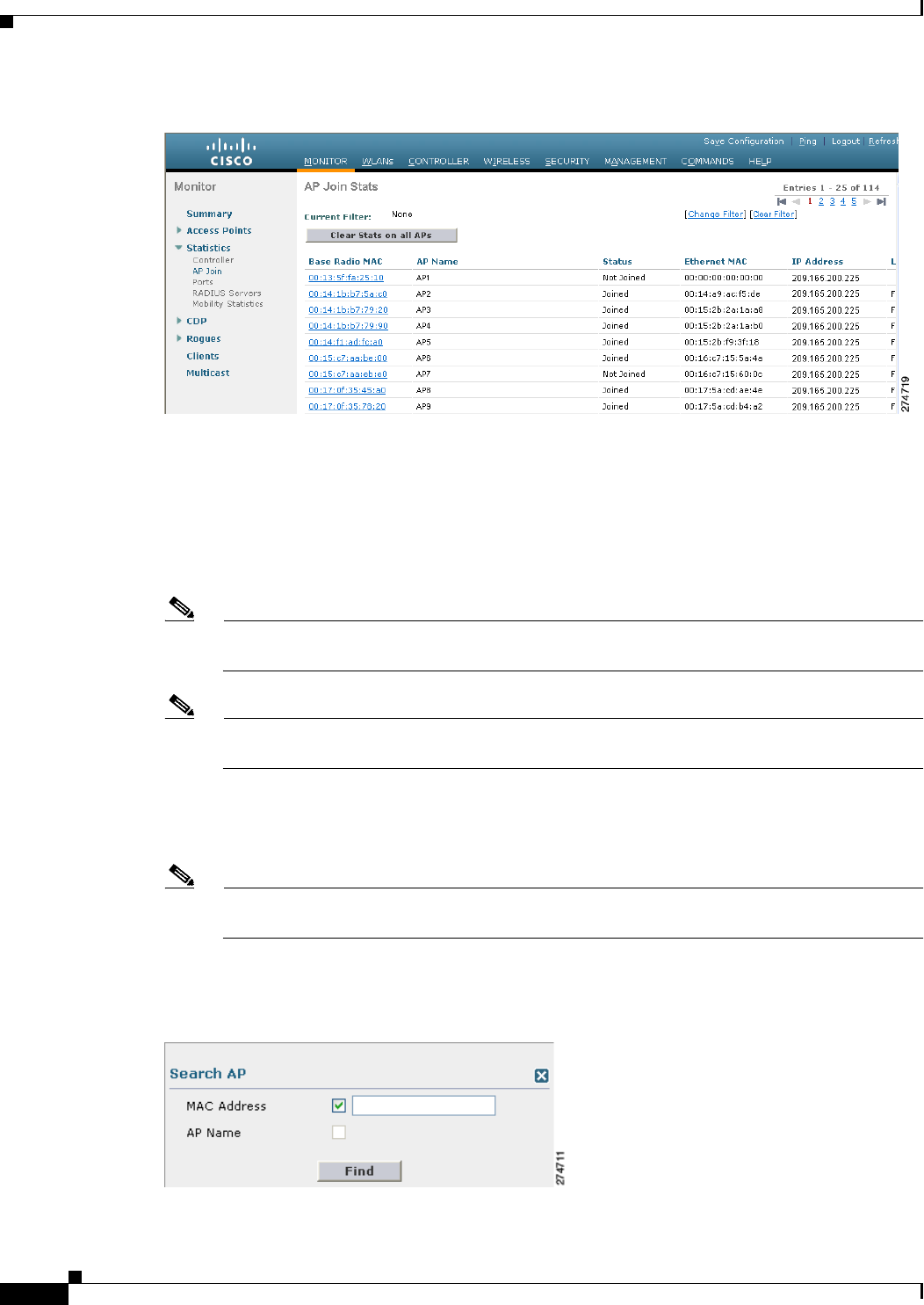
Step 1 Choose Monitor > Statistics > AP Join to open the AP Join Stats page (see Figure 8-15).
8-56
Cisco Wireless LAN Controller Configuration Guide
OL-21524-02
Chapter 8 Controlling Lightweight Access Points
Autonomous Access Points Converted to Lightweight Mode
Figure 8-15 AP Join Stats Page
This page lists all of the access points that are joined to the controller or that have tried to join. It shows
the radio MAC address, access point name, current join status, Ethernet MAC address, IP address, and
last join time for each access point.
The total number of access points appears in the upper right-hand corner of the page. If the list of access
points spans multiple pages, you can view these pages by clicking the page number links. Each page
shows the join statistics for up to 25 access points.
Note If you want to remove an access point from the list, hover your cursor over the blue drop-down
arrow for that access point and click Remove.
Note If you want to clear the statistics for all access points and start over, click Clear Stats on All
APs.
Step 2 If you want to search for specific access points in the list of access points on the AP Join Stats page,
follow these steps to create a filter to display only access points that meet certain criteria (such as MAC
address or access point name).
Note This feature is especially useful if your list of access points spans multiple pages, preventing you
from viewing them all at once.
a. Click Change Filter to open the Search AP dialog box (see Figure 8-16).
Figure 8-16 Search AP Dialog Box

8-57
Cisco Wireless LAN Controller Configuration Guide
OL-21524-02
Chapter 8 Controlling Lightweight Access Points
Autonomous Access Points Converted to Lightweight Mode
b. Select one of the following check boxes to specify the criteria used when displaying access points:
• MAC Address—Enter the base radio MAC address of an access point.
• AP Name—Enter the name of an access point.
Note When you enable one of these filters, the other filter is disabled automatically.
c. Click Find to commit your changes. Only the access points that match your search criteria appear
on the AP Join Stats page, and the Current Filter parameter at the top of the page specifies the filter
used to generate the list (for example, MAC Address:00:1e:f7:75:0a:a0 or AP Name:pmsk-ap).
Note If you want to remove the filter and display the entire access point list, click Clear Filter.
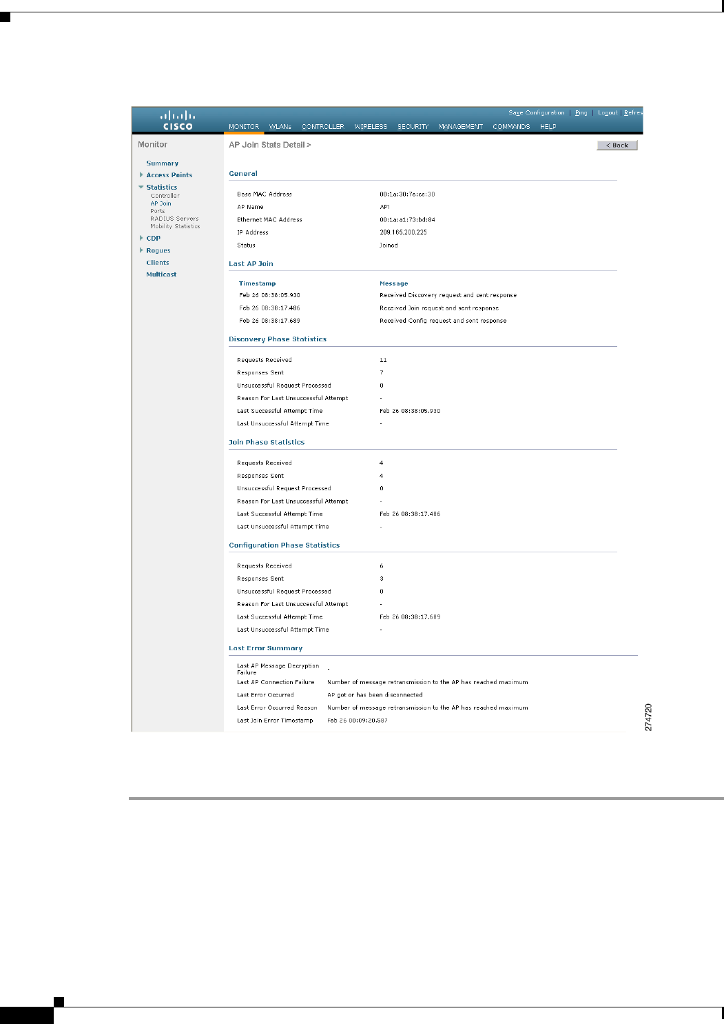
Step 3 To see detailed join statistics for a specific access point, click the radio MAC address of the access point.
The AP Join Stats Detail page appears (see Figure 8-17).
8-58
Cisco Wireless LAN Controller Configuration Guide
OL-21524-02
Chapter 8 Controlling Lightweight Access Points
Autonomous Access Points Converted to Lightweight Mode
Figure 8-17 AP Join Stats Detail Page
This page provides information from the controller’s perspective on each phase of the join process and
shows any errors that have occurred.
Using the CLI to View Access Point Join Information
Use these CLI commands to see access point join information:
• See the MAC addresses of all the access points that are joined to the controller or that have tried to
join by entering this command:
show ap join stats summary all

8-59
Cisco Wireless LAN Controller Configuration Guide
OL-21524-02
Chapter 8 Controlling Lightweight Access Points
Autonomous Access Points Converted to Lightweight Mode
Information similar to the following appears:
Number of APs.............................................. 4
Base Mac AP EthernetMac AP Name IP Address Status
00:0b:85:57:bc:c0 00:0b:85:57:bc:c0 AP1130 10.10.163.217 Joined
00:1c:0f:81:db:80 00:1c:63:23:ac:a0 AP1140 10.10.163.216 Not joined
00:1c:0f:81:fc:20 00:1b:d5:9f:7d:b2 AP1 10.10.163.215 Joined
00:21:1b:ea:36:60 00:0c:d4:8a:6b:c1 AP2 10.10.163.214 Not joined
• See the last join error detail for a specific access point by entering this command:
show ap join stats summary ap_mac
where ap_mac is the MAC address of the 802.11 radio interface.
Note To obtain the MAC address of the 802.11 radio interface, enter the show interfaces
Dot11Radio 0 command on the access point.
Information similar to the following appears:
Is the AP currently connected to controller................ Yes
Time at which the AP joined this controller last time...... Aug 21 12:50:36.061
Type of error that occurred last........................... AP got or has been
disconnected
Reason for error that occurred last........................ The AP has been reset by
the controller
Time at which the last join error occurred.............. Aug 21 12:50:34.374
• See all join-related statistics collected for a specific access point by entering this command:
show ap join stats detailed ap_mac
Information similar to the following appears:
Discovery phase statistics
- Discovery requests received.............................. 2
- Successful discovery responses sent...................... 2
- Unsuccessful discovery request processing................ 0
- Reason for last unsuccessful discovery attempt........... Not applicable
- Time at last successful discovery attempt................ Aug 21 12:50:23.335
- Time at last unsuccessful discovery attempt.............. Not applicable
Join phase statistics
- Join requests received................................... 1
- Successful join responses sent........................... 1
- Unsuccessful join request processing..................... 1
- Reason for last unsuccessful join attempt................ RADIUS authorization
is pending for the AP
- Time at last successful join attempt..................... Aug 21 12:50:34.481
- Time at last unsuccessful join attempt................... Aug 21 12:50:34.374
Configuration phase statistics
- Configuration requests received.......................... 1
- Successful configuration responses sent.................. 1
- Unsuccessful configuration request processing............ 0
- Reason for last unsuccessful configuration attempt....... Not applicable
- Time at last successful configuration attempt............ Aug 21 12:50:34.374
- Time at last unsuccessful configuration attempt.......... Not applicable
Last AP message decryption failure details
- Reason for last message decryption failure............... Not applicable

8-60
Cisco Wireless LAN Controller Configuration Guide
OL-21524-02
Chapter 8 Controlling Lightweight Access Points
Autonomous Access Points Converted to Lightweight Mode
Last AP disconnect details
- Reason for last AP connection failure.................... The AP has been reset by
the controller
Last join error summary
- Type of error that occurred last......................... AP got or has been
disconnected
- Reason for error that occurred last...................... The AP has been reset by
the controller
- Time at which the last join error occurred............... Aug 21 12:50:34.374
• Clear the join statistics for all access points or for a specific access point by entering this command:
clear ap join stats {all | ap_mac}
Using a Controller to Send Debug Commands to Access Points Converted to
Lightweight Mode
You can enable the controller to send debug commands to an access point converted to lightweight mode
by entering this command:
debug ap {enable | disable | command cmd} Cisco_AP
When this feature is enabled, the controller sends debug commands to the converted access point as
character strings. You can send any debug command supported by Cisco Aironet access points that run
Cisco IOS software in lightweight mode.
Understanding How Converted Access Points Send Crash Information to the
Controller
When a converted access point unexpectedly reboots, the access point stores a crash file on its local flash
memory at the time of the crash. After the unit reboots, it sends the reason for the reboot to the controller.
If the unit rebooted because of a crash, the controller pulls up the crash file using existing CAPWAP
messages and stores it in the controller flash memory. The crash info copy is removed from the access
point flash memory when the controller pulls it from the access point.
Understanding How Converted Access Points Send Radio Core Dumps to the
Controller
When a radio module in a converted access point generates a core dump, the access point stores the core
dump file of the radio on its local flash memory at the time of the radio crash. It sends a notification
message to the controller indicating which radio generated a core dump file. The controller sends a trap
that alerts you so that you can retrieve the radio core file from the access point.
The retrieved core file is stored in the controller flash and can be uploaded through TFTP or FTP to an
external server for analysis. The core file is removed from the access point flash memory when the
controller pulls it from the access point.
8-61
Cisco Wireless LAN Controller Configuration Guide
OL-21524-02
Chapter 8 Controlling Lightweight Access Points
Autonomous Access Points Converted to Lightweight Mode
Using the CLI to Retrieve Radio Core Dumps
To retrieve the radio core dump file using the controller CLI, follow these steps:
Step 1 Transfer the radio core dump file from the access point to the controller by entering this command:
config ap crash-file get-radio-core-dump slot Cisco_AP
For the slot parameter, enter the slot ID of the radio that crashed.
Step 2 Verify that the file was downloaded to the controller by entering this command:
show ap crash-file
Information similar to the following appears:
Local Core Files:
lrad_AP1130.rdump0 (156)
The number in parentheses indicates the size of the file. The size should be greater than
zero if a core dump file is available.
Using the GUI to Upload Radio Core Dumps
To upload the radio core dump file to a TFTP or FTP server using the controller GUI, follow these steps:
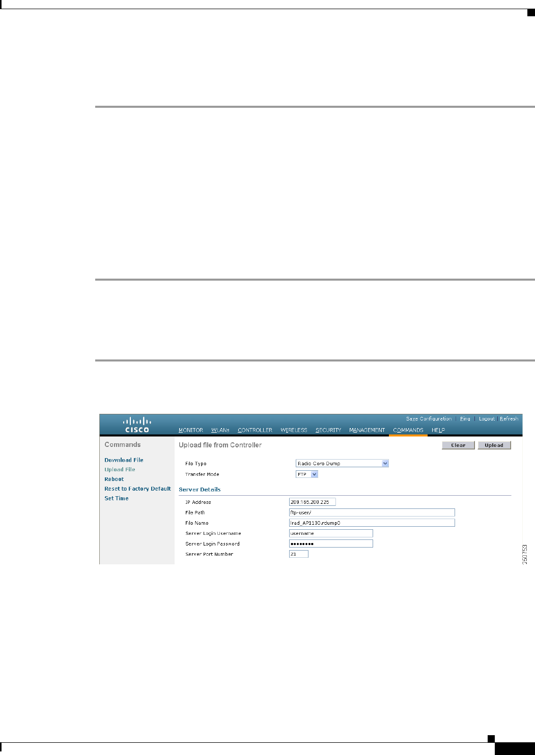
Step 1 Choose Commands > Upload File to open the Upload File from Controller page (see Figure 8-18).
Figure 8-18 Upload File from Controller Page
Step 2 From the File Type drop-down list, choose Radio Core Dump.
Step 3 From the Transfer Mode drop-down list, choose TFTP or FTP.
Step 4 In the IP Address text box, enter the IP address of the TFTP or FTP server.
Step 5 In the File Path text box, enter the directory path of the file.
Step 6 In the File Name text box, enter the name of the radio core dump file.

8-62
Cisco Wireless LAN Controller Configuration Guide
OL-21524-02
Chapter 8 Controlling Lightweight Access Points
Autonomous Access Points Converted to Lightweight Mode
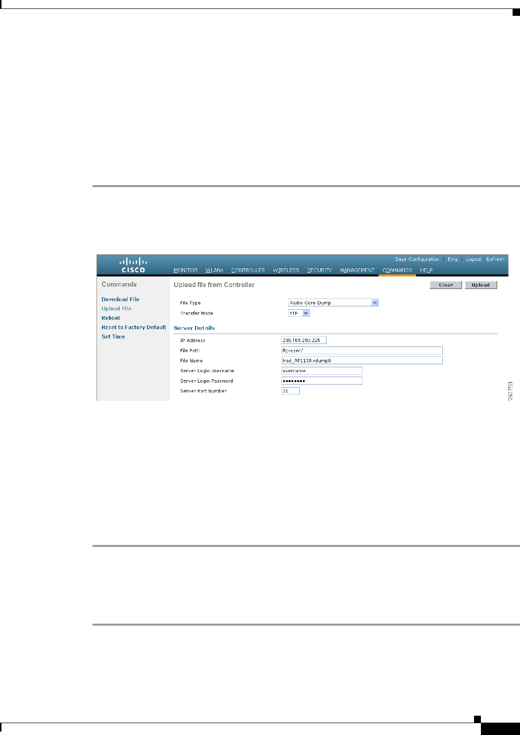
Note The filename that you enter should match the filename generated on the controller. You can
determine the filename on the controller by entering the show ap crash-file command.
Step 7 If you chose FTP as the Transfer Mode, follow these steps:
a. In the Server Login Username text box, enter the FTP server login name.
b. In the Server Login Password text box, enter the FTP server login password.
c. In the Server Port Number text box, enter the port number of the FTP server. The default value for
the server port is 21.
Step 8 Click Upload to upload the radio core dump file from the controller. A message appears indicating the
status of the upload.
Using the CLI to Upload Radio Core Dumps
To upload the radio core dump file to a TFTP or FTP server using the controller CLI, follow these steps:
Step 1 Transfer the file from the controller to a TFTP or FTP server by entering these commands:
• transfer upload mode {tftp | ftp}
• transfer upload datatype radio-core-dump
• transfer upload serverip server_ip_address
• transfer upload path server_path_to_file
• transfer upload filename filename
Note The filename that you enter should match the filename generated on the controller. You can
determine the filename on the controller by entering the show ap crash-file command.
Step 2 If you are using an FTP server, also enter these commands:
• transfer upload username username
• transfer upload password password
• transfer upload port port
Note The default value for the port parameter is 21.
Step 3 View the updated settings by entering this command:
transfer upload start
Step 4 When prompted to confirm the current settings and start the software upload, answer y.
8-63
Cisco Wireless LAN Controller Configuration Guide
OL-21524-02
Chapter 8 Controlling Lightweight Access Points
Autonomous Access Points Converted to Lightweight Mode
Uploading Memory Core Dumps from Converted Access Points
By default, access points converted to lightweight mode do not send memory core dumps to the
controller. This section provides instructions to upload access point core dumps using the controller GUI
or CLI.
Using the GUI to Upload Access Point Core Dumps
To upload a core dump file of the access point using the controller GUI, follow these steps:
Step 1 Choose Wireless > Access Points > All APs > access point name > and choose the Advanced tab to
open the All APs > Details for (Advanced) page (see Figure 8-19).
Figure 8-19 All APs > Details for (Advanced) Page
Step 2 Select the AP Core Dump check box to upload a core dump of the access point.
Step 3 In the TFTP Server IP text box, enter the IP address of the TFTP server.
Step 4 In the File Name text box, enter a name of the access point core dump file (such as dump.log).
Step 5 Select the File Compression check box to compress the access point core dump file. When you enable
this option, the file is saved with a .gz extension (such as dump.log.gz). This file can be opened with
WinZip.
Step 6 Click Apply to commit your changes.
Step 7 Click Save Configuration to save your changes.
Using the CLI to Upload Access Point Core Dumps
To upload a core dump file of the access point using the controller CLI, follow these steps:
Step 1 Upload a core dump of the access point by entering this command on the controller:
config ap core-dump enable tftp_server_ip_address filename {compress | uncompress} {ap_name |
all}
where

8-64
Cisco Wireless LAN Controller Configuration Guide
OL-21524-02
Chapter 8 Controlling Lightweight Access Points
Autonomous Access Points Converted to Lightweight Mode
• tftp_server_ip_address is the IP address of the TFTP server to which the access point sends core
dump files.
Note The access point must be able to reach the TFTP server.
• filename is the name that the access points uses to label the core file.
• compress configures the access point to send compressed core files whereas uncompress
configures the access point to send uncompressed core files.
Note When you choose compress, the file is saved with a .gz extension (for example,
dump.log.gz). This file can be opened with WinZip.
• ap_name is the name of a specific access point for which core dumps are uploaded and all is all
access points converted to lightweight mode.
Step 2 Save your changes by entering this command:
save config
Viewing the AP Crash Log Information
Note Whenever the controller reboots or upgrades, the AP crash log information gets deleted from the
controller. We recommend that you make a backup of AP crash log information before rebooting or
upgrading the controller.
Using the GUI to View the AP Crash Log information
To view the AP crash log information using the controller GUI, follow these steps:
Step 1 Choose Management > Tech Support > AP Crash Log to open the AP Crash Logs page
(see Figure 8-20).

8-65
Cisco Wireless LAN Controller Configuration Guide
OL-21524-02
Chapter 8 Controlling Lightweight Access Points
Autonomous Access Points Converted to Lightweight Mode
Figure 8-20 AP Crash Logs Page
Using the CLI to View the AP Crash Log information
To retrieve the AP crash log information using the controller CLI, follow these steps:
Step 1 Verify that the crash file was downloaded to the controller by entering this command:
show ap crash-file
Information similar to the following appears:
Local Core Files:
lrad_AP1130.rdump0 (156)
The number in parentheses indicates the size of the file. The size should be greater than
zero if a core dump file is available.
Step 2 See the contents of the AP crash log file by entering this command:
show ap crash-file Cisoc_AP
Displaying MAC Addresses for Converted Access Points
There are some differences in the way that controllers display the MAC addresses of converted access
points on information pages in the controller GUI:
• On the AP Summary page, the controller lists the Ethernet MAC addresses of converted access
points.
• On the AP Detail page, the controller lists the BSS MAC addresses and Ethernet MAC addresses of
converted access points.
• On the Radio Summary page, the controller lists converted access points by radio MAC address.

8-66
Cisco Wireless LAN Controller Configuration Guide
OL-21524-02
Chapter 8 Controlling Lightweight Access Points
Autonomous Access Points Converted to Lightweight Mode
Disabling the Reset Button on Access Points Converted to Lightweight Mode
You can disable the reset button on access points converted to lightweight mode. The reset button is
labeled MODE on the outside of the access point.
Use this command to disable or enable the reset button on one or all converted access points associated
to a controller:
config ap reset-button {enable | disable} {ap-name | all}
The reset button on converted access points is enabled by default.
Configuring a Static IP Address on a Lightweight Access Point
If you want to specify an IP address for an access point rather than having one assigned automatically
by a DHCP server, you can use the controller GUI or CLI to configure a static IP address for the access
point. Static IP addresses are generally used only for deployments with a limited number of users.
Note See the “Configuring DHCP” section on page 7-10 for information on assigning IP addresses using
DHCP.
An access point cannot discover the controller using domain name system (DNS) resolution if a static
IP address is configured for the access point, unless you specify a DNS server and the domain to which
the access point belongs. Previously, these parameters could be configured only using the CLI, but
controller software release 6.0 or later releases expand this functionality to the GUI.
Note If you configure an access point to use a static IP address that is not on the same subnet on which the
access point’s previous DHCP address was, the access point falls back to a DHCP address after the
access point reboots. If the access point falls back to a DHCP address, enter the show ap config general
Cisco_AP CLI command to show that the access point is using a fallback IP address. However, the GUI
shows both the static IP address and the DHCP address, but it does not identify the DHCP address as a
fallback address.
Using the GUI to Configure a Static IP Address
To configure a static IP address for a lightweight access point using the controller GUI, follow these
steps:
Step 1 Choose Wireless > Access Points > All APs to open the All APs page.
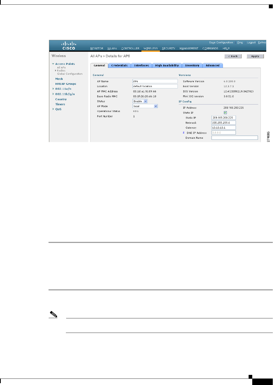
Step 2 Click the name of the access point for which you want to configure a static IP address. The All APs >
Details for (General) page appears (see Figure 8-21).
8-67
Cisco Wireless LAN Controller Configuration Guide
OL-21524-02
Chapter 8 Controlling Lightweight Access Points
Autonomous Access Points Converted to Lightweight Mode
Figure 8-21 All APs > Details for (General) Page
Step 3 Under IP Config, select the Static IP check box if you want to assign a static IP address to this access
point. The default value is unselected.
Step 4 Enter the static IP address, netmask, and default gateway in the corresponding text boxes.
Step 5 Click Apply to commit your changes. The access point reboots and rejoins the controller, and the static
IP address that you specified in Step 4 is sent to the access point.
Step 6 After the static IP address has been sent to the access point, you can configure the DNS server IP address
and domain name as follows:
a. In the DNS IP Address text box, enter the IP address of the DNS server.
b. In the Domain Name text box, enter the name of the domain to which the access point belongs.
c. Click Apply to commit your changes.
d. Click Save Configuration to save your changes.
Using the CLI to Configure a Static IP Address
To configure a static IP address for a lightweight access point using the controller CLI, follow these
steps:
Step 1 Configure a static IP address on the access point by entering this command:
config ap static-ip enable Cisco_AP ip_address mask gateway
Note To disable static IP for the access point, enter the config ap static-ip disable Cisco_AP
command.
Step 2 Save your changes by entering this command:
save config

8-68
Cisco Wireless LAN Controller Configuration Guide
OL-21524-02
Chapter 8 Controlling Lightweight Access Points
Autonomous Access Points Converted to Lightweight Mode
The access point reboots and rejoins the controller, and the static IP address that you specified in Step 1
is pushed to the access point.
Step 3 After the static IP address has been sent to the access point, you can configure the DNS server IP address
and domain name as follows:
a. To specify a DNS server so that a specific access point or all access points can discover the controller
using DNS resolution, enter this command:
config ap static-ip add nameserver {Cisco_AP | all} ip_address
Note To delete a DNS server for a specific access point or all access points, enter the config ap
static-ip delete nameserver {Cisco_AP | all} command.
b. To specify the domain to which a specific access point or all access points belong, enter this
command:
config ap static-ip add domain {Cisco_AP | all} domain_name
Note To delete a domain for a specific access point or all access points, enter this command:
config ap static-ip delete domain {Cisco_AP | all}.
c. To save your changes, enter this command:
save config
Step 4 See the IP address configuration for the access point by entering this command:
show ap config general Cisco_AP
Information similar to the following appears:
Cisco AP Identifier.............................. 4
Cisco AP Name................................. AP6
...
IP Address Configuration......................... Static IP assigned
IP Address....................................... 10.10.10.118
IP NetMask....................................... 255.255.255.0
Gateway IP Addr............................... 10.10.10.1
Domain........................................... Domain1
Name Server................................... 10.10.10.205
...
Supporting Oversized Access Point Images
Controller software release 5.0 or later releases allow you to upgrade to an oversized access point image
by automatically deleting the recovery image to create sufficient space. This feature affects only access
points with 8 MB of flash (the 1100, 1200, and 1310 series access points). All newer access points have
a larger flash size than 8 MB.
Note As of August 2007, there are no oversized access point images, but as new features are added, the access
point image size will continue to grow.
8-69
Cisco Wireless LAN Controller Configuration Guide
OL-21524-02
Chapter 8 Controlling Lightweight Access Points
OfficeExtend Access Points
The recovery image provides a backup image that can be used if an access point power-cycles during an
image upgrade. The best way to avoid the need for access point recovery is to prevent an access point
from power-cycling during a system upgrade. If a power-cycle occurs during an upgrade to an oversized
access point image, you can recover the access point using the TFTP recovery procedure.
To perform the TFTP recovery procedure, follow these steps:
Step 1 Download the required recovery image from Cisco.com (c1100-rcvk9w8-mx, c1200-rcvk9w8-mx, or
c1310-rcvk9w8-mx) and install it in the root directory of your TFTP server.
Step 2 Connect the TFTP server to the same subnet as the target access point and power-cycle the access point.
The access point boots from the TFTP image and then joins the controller to download the oversized
access point image and complete the upgrade procedure.
Step 3 After the access point has been recovered, you may remove the TFTP server.
OfficeExtend Access Points
An OfficeExtend access point provides secure communications from a controller to an access point at a
remote location, seamlessly extending the corporate WLAN over the Internet to an employee’s
residence. The user’s experience at the home office is exactly the same as it would be at the corporate
office. Datagram Transport Layer Security (DTLS) encryption between the access point and the
controller ensures that all communications have the highest level of security.
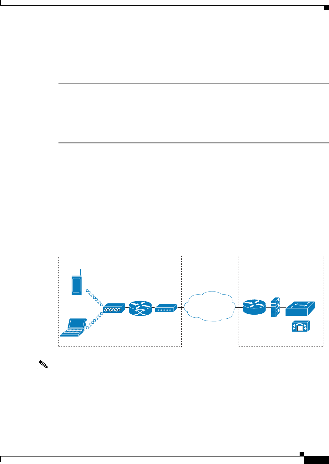
Figure 8-22 shows a typical OfficeExtend access point setup.
Figure 8-22 Typical OfficeExtend Access Point Setup
Note OfficeExtend access points are designed to work behind a router or other gateway device that is using
network address translation (NAT). NAT allows a device, such as a router, to act as an agent between the
Internet (public) and a personal network (private), enabling an entire group of computers to be
represented by a single IP address. In controller software release 6.0 or later releases, only one
OfficeExtend access point can be deployed behind a single NAT device.
Currently, Cisco 1040, 1130, 1140, and 3502I series access points that are joined to a Cisco 5500 Series
Controller can be configured to operate as OfficeExtend access points.
M
OfficeExtend
Access
Point
Corporate
SSID
Router
Home Office
DSL/Cable
modem Controller/CCM
205774

8-70
Cisco Wireless LAN Controller Configuration Guide
OL-21524-02
Chapter 8 Controlling Lightweight Access Points
OfficeExtend Access Points
OEAP 600 Series Access Points
This section details the requirements for configuring a Cisco wireless LAN controller for use with the
Cisco 600 Series OfficeExtend Access Point. The 600 Series OfficeExtend Access Point supports split
mode operation, and it requires configuration through the WLAN controller in local mode. This section
describes the configurations necessary for proper connection and supported feature sets.
Note The Cisco 600 Series OfficeExtend access points are designed to work behind a router or other gateway
device that is using Network Address Translation (NAT). NAT allows a device, such as a router, to act
as an agent between the Internet (public) and a personal network (private), enabling an entire group of
computers to be represented by a single IP address. In controller software release 6.0 or later releases,
only one OfficeExtend access point can be deployed behind a single NAT device.
Note The following ports must be open on the firewall between the WLAN controller and the 600 Series
OfficeExtend Access Point: CAPWAP UDP 5246 and 5247
Supported Controller Platforms
The 600 Series OfficeExtend Access Point is supported on the Cisco 5508 Series Controller, WISM-2,
and Cisco 2500 Series Controllers and requires the controller software 7.0.116.0 release.
The 600 Series OfficeExtend Access Point has DTLS permanently enabled. You cannot disable DTLS
on this access point.
OEAP in Local Mode
The 600 Series OfficeExtend Access Point connects to the controller in local mode. You cannot alter
these settings.
Note Monitor mode, H-REAP mode, sniffer mode, rogue detector, bridge, and SE-Connect are not supported
on the 600 Series OfficeExtend Access Point and are not configurable.
8-71
Cisco Wireless LAN Controller Configuration Guide
OL-21524-02
Chapter 8 Controlling Lightweight Access Points
OfficeExtend Access Points
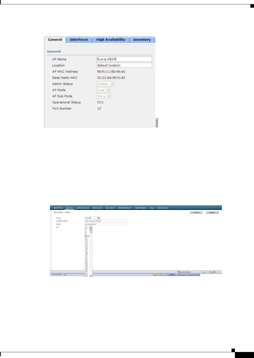
Figure 8-23 OEAP Mode
Supported WLAN Settings for 600 Series OfficeExtend Access Point
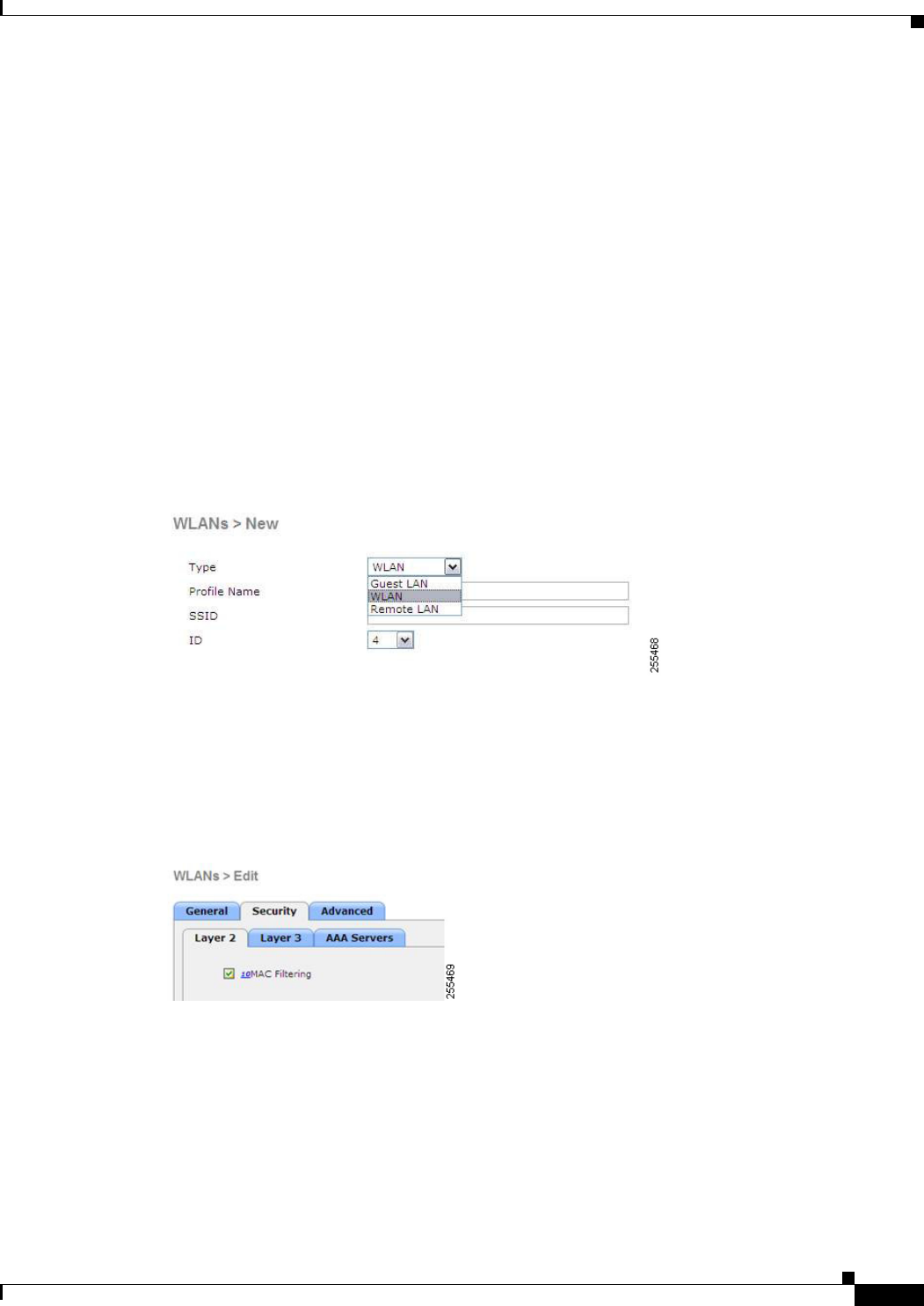
The 600 Series OfficeExtend Access Point supports a maximum of two WLANs and one remote LAN.
If your network deployment has more than two WLANs, you must place the 600 Series OfficeExtend
Access Point in an AP group. If the 600 Series OfficeExtend Access Points are added to an AP group,
the same limit of two WLANs and one remote LAN still applies for the configuration of the AP group.
If the 600 Series OfficeExtend Access Point is in the default group, which means that it is not in a defined
AP group, the WLAN/remote LAN IDs must be set lower than ID 8.
Figure 8-24 WLAN ID for OEAP
If additional WLANs or remote LANs are created with the intent of changing the WLANs or remote
LAN being used by the 600 Series OfficeExtend Access Point, you must disable the current WLANs or
remote LAN that you are removing before enabling the new WLANs or remote LAN on the 600 Series
OfficeExtend Access Point. If there are more than one remote LANs enabled for an AP group, disable
all remote LANs and then enable only one of them.
8-72
Cisco Wireless LAN Controller Configuration Guide
OL-21524-02
Chapter 8 Controlling Lightweight Access Points
OfficeExtend Access Points
If more than two WLANs are enabled for an AP group, disable all WLANs and then enable only two of
them.
For more information on WLANs, see Chapter 7, “Configuring WLANs.”
WLAN Security Settings for the 600 Series OfficeExtend Access Point
When configuring the security settings in the WLAN, note that there are specific elements that are not
supported on the 600 Series OfficeExtend Access Point. CCX is not supported on the 600 Series
OfficeExtend Access Point, and elements related to CCX are not supported.
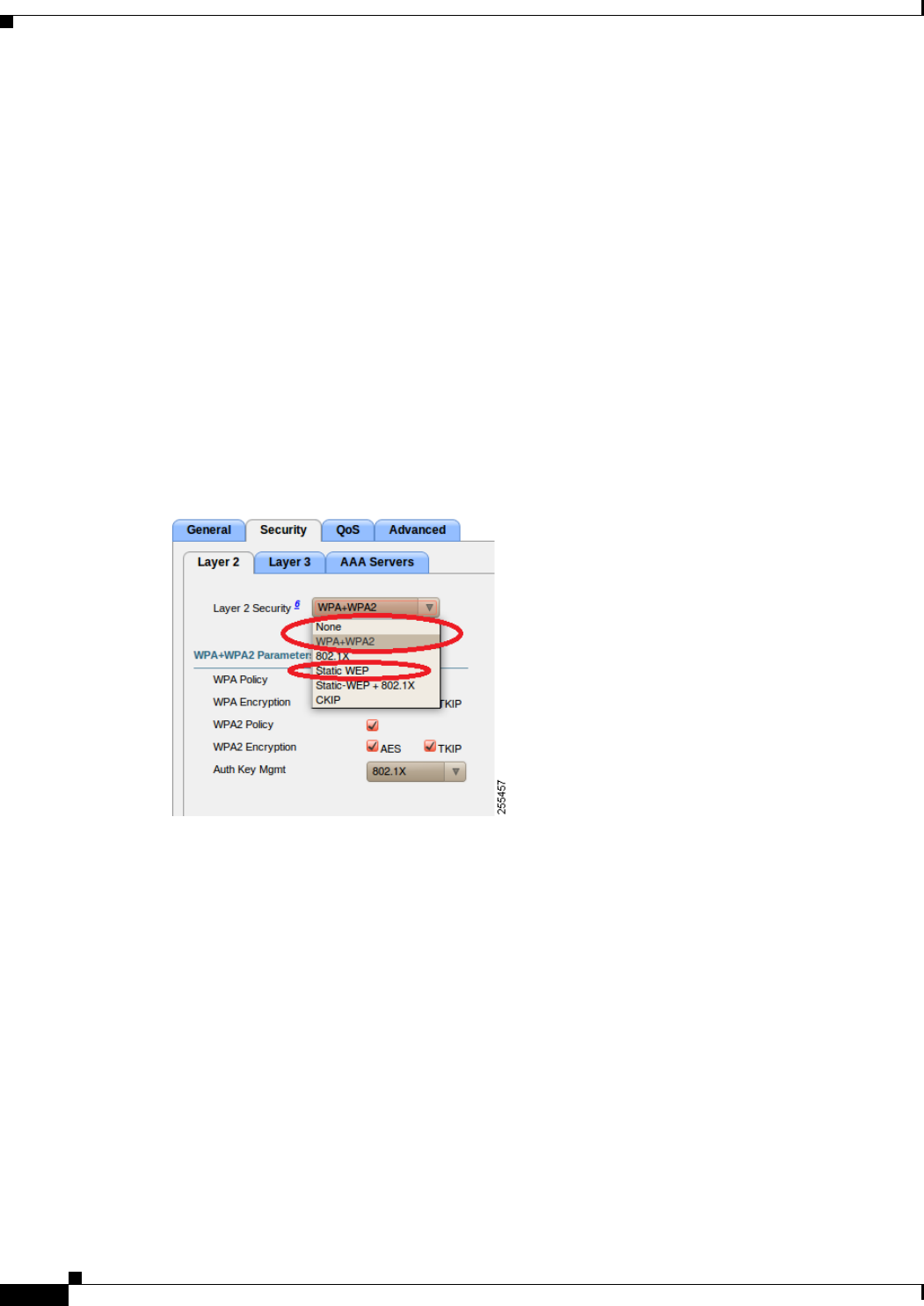
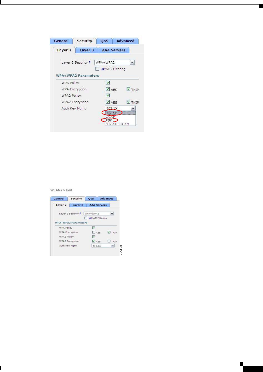
For Layer 2 Security, the following options are supported for the 600 Series OfficeExtend Access Point:
• None
• WPA+WPA2
• Static WEP
Figure 8-25 WLAN Security Settings
In the Security tab, do not select CCKM in WPA + WPA2 settings. Select only 802.1x or PSK.
Figure 8-26 WLAN Security Settings
8-73
Cisco Wireless LAN Controller Configuration Guide
OL-21524-02
Chapter 8 Controlling Lightweight Access Points
OfficeExtend Access Points
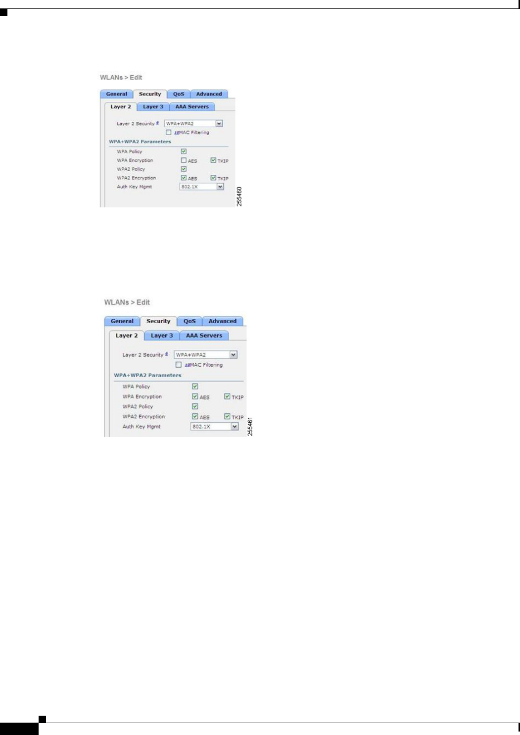
Security encryption settings must be identical for WPA and WPA2 for TKIP and AES. The following are
examples of incompatible settings for TKIP and AES.
Figure 8-27 and Figure 8-28 display the incompatible configuration
Figure 8-27 Incompitable WPA and WPA2 Security Encryption Settings for OEAP 600 Series
Figure 8-28 Incompitable WPA and WPA2 Security Enctyption Settings for OEAP 600 Series.
8-74
Cisco Wireless LAN Controller Configuration Guide
OL-21524-02
Chapter 8 Controlling Lightweight Access Points
OfficeExtend Access Points
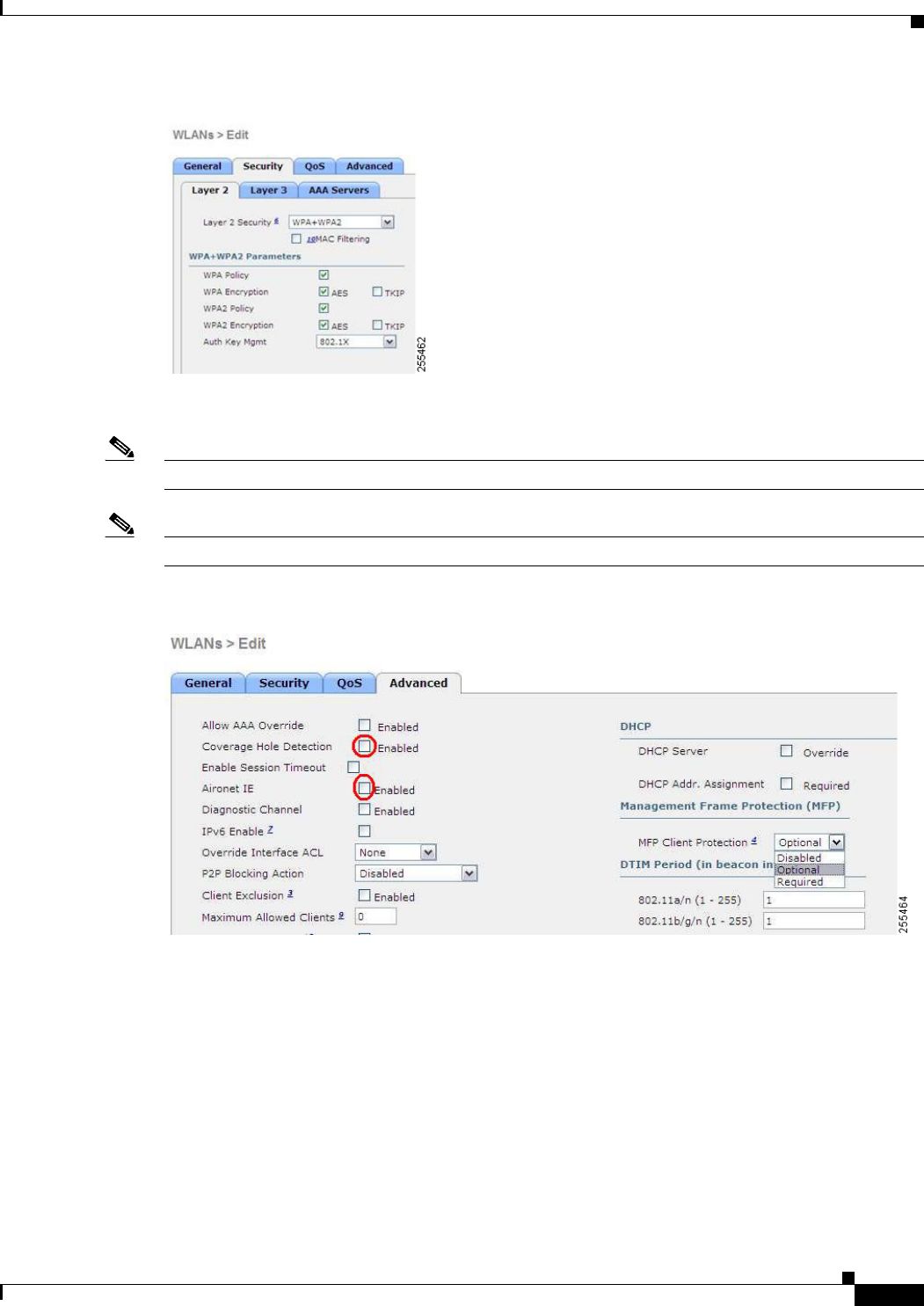
The following are examples of compatible settings:
Figure 8-29 Compitable Security Settings for OEAP Series.
Figure 8-30
8-75
Cisco Wireless LAN Controller Configuration Guide
OL-21524-02
Chapter 8 Controlling Lightweight Access Points
OfficeExtend Access Points
QOS settings are supported, but CAC is not supported and should not be enabled.
Note Coverage Hole Detection should not be enabled.
Note Aironet IE should not be enabled. This option is not supported.
Figure 8-31 QoS Settings for OEAP 600
MFP is also not supported and should be disabled or set to optional.
Figure 8-32 MPF Settings for OEAP Series Access Points
8-76
Cisco Wireless LAN Controller Configuration Guide
OL-21524-02
Chapter 8 Controlling Lightweight Access Points
OfficeExtend Access Points
Client Load Balancing and Client Band Select are not supported:
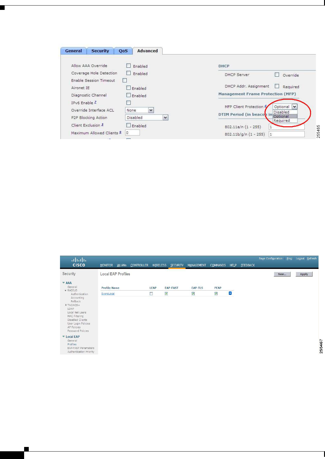
Authentication Settings
For authentication on the 600 Series OfficeExtend Access Point, LEAP is not supported. This
configuration needs to be addressed on the clients and radius servers to migrate them to EAP-Fast,
EAP-TTLS, EAP-TLS, or PEAP.
If Local EAP is being utilized on the controller, then the settings would also have to be modified not to
utilize LEAP:
Figure 8-33 Local EAP Profiles
Supported User Count on 600 Series OfficeExtend Access Point
Only fifteen users are allowed to connect on the WLAN Controller WLANs provided on the 600 Series
OfficeExtend Access Point at any one time, a sixteenth user cannot authenticate until one of the first
clients is deauthenticated or timeout on the controller occurs. This number is cumulative across the
controller WLANs on the 600 Series OfficeExtend Access Point.
8-77
Cisco Wireless LAN Controller Configuration Guide
OL-21524-02
Chapter 8 Controlling Lightweight Access Points
OfficeExtend Access Points
For example, if two controller WLANs are configured and there are fifteen users on one of the WLANs,
no users can join the other WLAN on the 600 Series OfficeExtend Access Point at that time.
This limit does not apply to the local private WLANs that the end user configures on the 600 Series
OfficeExtend Access Point for personal use. Clients connected on these private WLANs or on the wired
ports do not affect these limits.
Remote LAN Settings
Only four clients can connect through a remote LAN port on the 600 Series OfficeExtend Access Point.
This number does not affect the fifteen user limit imposed for the Controller WLANs. The remote LAN
client limit supports connecting a switch or hub to the remote LAN port for multiple devices or
connecting directly to a Cisco IP phone that is connected to that port. Only the first four devices can
connect connect until one of the devices is idle for more than one minute.
Remote LAN is configured in the same way that a WLAN or Guest LAN is configured on the controller:
Figure 8-34 Remote LAN Settings for OEAP 600 Series AP
Security settings can be left open, set for MAC filtering, or set for Web Authentication. The default is to
utilize MAC filtering.
Figure 8-35 shows the security settings for MAC filtering.
Figure 8-35 MAC filtering for OEAP 600 Series AP
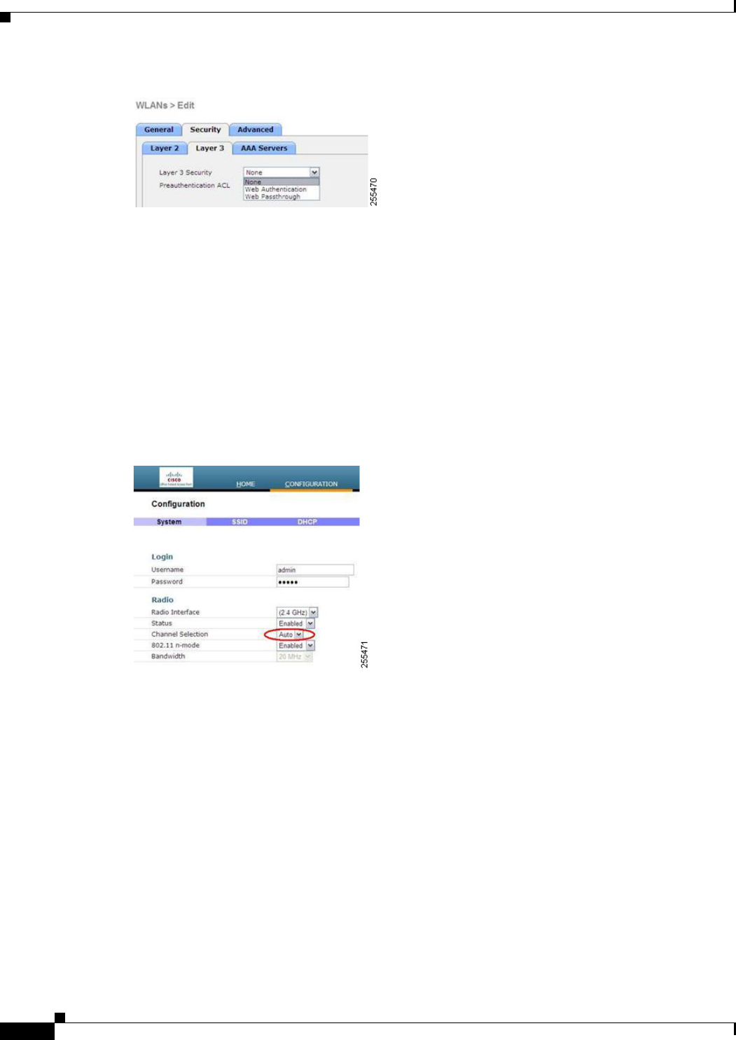
Figure 8-36 displays the Layer 4 security configuration.
Figure 8-36 Security Configuation for OEAP 600 AP
8-78
Cisco Wireless LAN Controller Configuration Guide
OL-21524-02
Chapter 8 Controlling Lightweight Access Points
OfficeExtend Access Points
Channel Management and Settings
The radios for the 600 Series OfficeExtend Access Point are controlled through the Local GUI on the
access point and not through the Wireless LAN Controller. Attempting to control the spectrum channel
or power, or to disable the radios through the controller does not have effect on the 600 Series
OfficeExtend Access Point. RRM is not supported on the 600 Series OfficeExtend Access Point.
The 600 series scans and chooses channels for 2.4GHz and 5.0GHz during startup as long as the default
settings on the local GUI are left as default in both spectrums.
Figure 8-37 Channel Selection for OEAP 600 Series APs
The channel bandwidth for 5.0 GHz is also configured on the 600 Series OfficeExtend Access Point
Local GUI, for 20 MHz or 40 MHz wide channels. Setting the channel width to 40 MHz for 2.4 GHz is
not supported and fixed at 20 MHz.

8-79
Cisco Wireless LAN Controller Configuration Guide
OL-21524-02
Chapter 8 Controlling Lightweight Access Points
OfficeExtend Access Points
Figure 8-38 Channel Width for OEAP 600 APs
Additional Caveats
The 600 Series OfficeExtend Access Points are designed for single AP deployments, therefore client
roaming between 600 Series OfficeExtend Access Points is not supported.
Disabling the 802.11a/n or 802.11b/g/n on the controller may not disable these spectrums on the 600
Series OfficeExtend Access Point since local SSID may be still working.
Note Your firewall must be configured to allow traffic from access points using CAPWAP. Make sure that
UDP ports 5246 and 5247 are enabled and are not blocked by an intermediate device that could prevent
an access point from joining the controller.
Implementing Security
Note Configuring LSC is not a requirement but an option.
To ensure that only valid OfficeExtend access points join the company network, follow these steps:
Step 1 Use local significant certificates (LSCs) to authorize your OfficeExtend access points, by following the
instructions in the “Authorizing Access Points Using LSCs” section on page 8-46.
Step 2 Implement AAA server validation using the access point’s MAC address, name, or both as the username
in authorization requests, by entering this command:
config auth-list ap-policy authorize-ap username {ap_mac | Cisco_AP | both}
Using the access point name for validation can ensure that only the OfficeExtend access points of valid
employees can join the controller. To implement this security policy, make sure to name each
OfficeExtend access point with an employee ID or employee number. When an employee is terminated,
run a script to remove this user from the AAA server database, which prevents that employee’s
OfficeExtend access point from joining the network.
Step 3 Save your changes by entering this command:

8-80
Cisco Wireless LAN Controller Configuration Guide
OL-21524-02
Chapter 8 Controlling Lightweight Access Points
OfficeExtend Access Points
save config
Note CCX is not supported on the 600 OEAP. Elements related to CCX are not supported. Also, only 802.1x
or PSK is supported. TKIP and AES security encryption settings must be identical for WPA and WPA2.
Licensing for an OfficeExtend Access Point
To use OfficeExtend access points, a base license must be installed and in use on the Cisco 5500 Series
Controller. After the license is installed, you can enable the OfficeExtend mode on an 1130 series or
1140 series access point.
Note See Chapter 4, “Configuring Controller Settings,” for information on obtaining and installing licenses.
Configuring OfficeExtend Access Points
After the 1130 series or 1140 series access point has joined the controller, you can configure it as an
OfficeExtend access point using the controller GUI or CLI.
Note Configuring LSC is not a requirement but an option.
Using the GUI to Configure OfficeExtend Access Points
To configure an OfficeExtend access point using the controller GUI, follow these steps:
Step 1 Enable hybrid REAP on the access point as follows:
a. Choose Wireless to open the All APs page.
b. Click the name of the desired access point. The All APs > Details for (General) page appears.
c. Choose H-REAP from the AP Mode drop-down list to enable hybrid REAP for this access point.
Note For more information on hybrid-REAP, see Chapter 15, “Configuring Hybrid REAP.”
Step 2 Configure one or more controllers for the access point as follows:
a. Choose the High Availability tab to open the All APs > Details for (High Availability) page.
b. Enter the name and IP address of the primary controller for this access point in the Primary
Controller Name and Management IP Address text boxes.
Note You must enter both the name and IP address of the controller. Otherwise, the access point
cannot join this controller.
8-81
Cisco Wireless LAN Controller Configuration Guide
OL-21524-02
Chapter 8 Controlling Lightweight Access Points
OfficeExtend Access Points
c. If desired, enter the name and IP address of a secondary or tertiary controller (or both) in the
corresponding Controller Name and Management IP Address text boxes.
d. Click Apply to commit your changes. The access point reboots and then rejoins the controller.
Note OfficeExtend access points do not use the generic broadcast or over-the air (OTAP) discovery
process to locate a controller. You must configure one or more controllers because OfficeExtend
access points try to connect only to their configured controllers.
Note The names and IP addresses must be unique for the primary, secondary, and tertiary controllers.
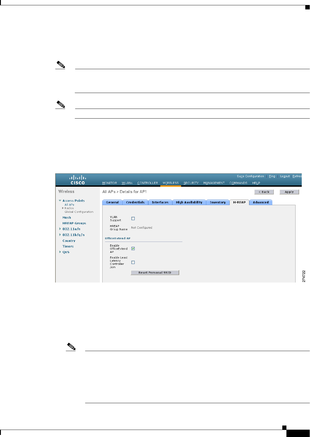
Step 3 Enable OfficeExtend access point settings as follows:
a. Click the access point name on the All APs page.
b. Choose the H-REAP tab to open the All APs > Details for (H-REAP) page (see Figure 8-39).
Figure 8-39 All APs > Details for (H-REAP) Page
c. Select the Enable OfficeExtend AP check box to enable the OfficeExtend mode for this access
point. The default value is selected.
Unselecting this check box disables OfficeExtend mode for this access point. It does not undo all of
the configuration settings on the access point. If you want to clear the access point’s configuration
and return it to the factory-default settings, enter clear ap config Cisco_AP on the controller CLI.
If you want to clear only the access point’s personal SSID, click Reset Personal SSID.
Note Rogue detection is disabled automatically when you enable the OfficeExtend mode for an
access point. However, you can enable or disable rogue detection for a specific access point
by selecting the Rogue Detection check box on the All APs > Details for (Advanced) page.
Rogue detection is disabled by default for OfficeExtend access points because these access
points, which are deployed in a home environment, are likely to detect a large number of
rogue devices. See the “Managing Rogue Devices” section on page 6-89 for more
information on rogue detection.

8-82
Cisco Wireless LAN Controller Configuration Guide
OL-21524-02
Chapter 8 Controlling Lightweight Access Points
OfficeExtend Access Points
Note DTLS data encryption is enabled automatically when you enable the OfficeExtend mode for
an access point. However, you can enable or disable DTLS data encryption for a specific
access point by selecting the Data Encryption check box on the All APs > Details for
(Advanced) page. See the “Configuring Data Encryption” section on page 8-2 for more
information on DTLS data encryption.
Note Telnet and SSH access are disabled automatically when you enable the OfficeExtend mode
for an access point. However, you can enable or disable Telnet or SSH access for a specific
access point by selecting the Telnet or SSH check box on the All APs > Details for
(Advanced) page. See the “Troubleshooting Access Points Using Telnet or SSH” section on
page D-48 for more information on Telnet and SSH.
Note Link latency is enabled automatically when you enable the OfficeExtend mode for an access
point. However, you can enable or disable link latency for a specific access point by
selecting the Enable Link Latency check box on the All APs > Details for (Advanced)
page. See the “Configuring Link Latency” section on page 8-124 for more information on
this feature.
d. Select the Enable Least Latency Controller Join check box if you want the access point to choose
the controller with the least latency when joining. Otherwise, leave this check box unselected, which
is the default value. When you enable this feature, the access point calculates the time between the
discovery request and discovery response and joins the Cisco 5500 Series Controller that responds
first.
e. Click Apply to commit your changes.
The OfficeExtend AP text box on the All APs page shows which access points are configured as
OfficeExtend access points.
Step 4 Configure a specific username and password for the OfficeExtend access point so that the user at home
can log into the GUI of the OfficeExtend access point:
a. Click the access point name on the All APs page again.
b. Choose the Credentials tab to open the All APs > Details for (Credentials) page.
c. Select the Over-ride Global Credentials check box to prevent this access point from inheriting the
global username, password, and enable password from the controller. The default value is
unselected.
d. In the Username, Password, and Enable Password text boxes, enter the unique username, password,
and enable password that you want to assign to this access point.
Note The information that you enter is retained across controller and access point reboots and if
the access point joins a new controller.
e. Click Apply to commit your changes.
f. Click Save Configuration to save your changes.

8-83
Cisco Wireless LAN Controller Configuration Guide
OL-21524-02
Chapter 8 Controlling Lightweight Access Points
OfficeExtend Access Points
Note If you want to force this access point to use the controller’s global credentials, unselect the
Over-ride Global Credentials check box.
Step 5 If your controller supports only OfficeExtend access points, see the “Configuring RRM” section on
page 13-10 for instructions on setting the recommended values for the DCA interval, channel scan
duration, and neighbor packet frequency.
Using the CLI to Configure OfficeExtend Access Points
To configure an OfficeExtend access point using the controller CLI, follow these steps:
Step 1 Enable hybrid-REAP on the access point by entering this command:
config ap mode h-reap Cisco_AP
Note For more information on hybrid-REAP, see Chapter 15, “Configuring Hybrid REAP.”
Step 2 Configure one or more controllers for the access point by entering one or all of these commands:
config ap primary-base controller_name Cisco_AP controller_ip_address
config ap secondary-base controller_name Cisco_AP controller_ip_address
config ap tertiary-base controller_name Cisco_AP controller_ip_address
Note You must enter both the name and IP address of the controller. Otherwise, the access point
cannot join this controller.
Note OfficeExtend access points do not use the generic broadcast or over-the air (OTAP) discovery
process to find a controller. You must configure one or more controllers because OfficeExtend
access points try to connect only to their configured controllers.
Note The names and IP addresses must be unique for the primary, secondary, and tertiary controllers.
Step 3 Enable the OfficeExtend mode for this access point by entering this command:
config hreap office-extend {enable | disable} Cisco_AP
The default value is enabled. The disable parameter disables OfficeExtend mode for this access point.
It does not undo all of the configuration settings on the access point. If you want to clear the access
point’s configuration and return it to the factory-default settings, enter this command:
clear ap config Cisco_AP
If you want to clear only the access point’s personal SSID, enter this command:
config hreap office-extend clear-personalssid-config Cisco_AP.

8-84
Cisco Wireless LAN Controller Configuration Guide
OL-21524-02
Chapter 8 Controlling Lightweight Access Points
OfficeExtend Access Points
Note Rogue detection is disabled automatically when you enable the OfficeExtend mode for an access
point. However, you can enable or disable rogue detection for a specific access point or for all
access points using the config rogue detection {enable | disable} {Cisco_AP | all} command.
Rogue detection is disabled by default for OfficeExtend access points because these access
points, which are deployed in a home environment, are likely to detect a large number of rogue
devices. See the “Managing Rogue Devices” section on page 6-89 for more information on
rogue detection.
Note DTLS data encryption is enabled automatically when you enable the OfficeExtend mode for an
access point. However, you can enable or disable DTLS data encryption for a specific access
point or for all access points using the config ap link-encryption {enable | disable} {Cisco_AP
| all} command. See the “Configuring Data Encryption” section on page 8-2 for more
information on DTLS data encryption.
Note Telnet and SSH access are disabled automatically when you enable the OfficeExtend mode for
an access point. However, you can enable or disable Telnet or SSH access for a specific access
point using the config ap {telnet | ssh} {enable | disable} Cisco_AP command. See the
“Troubleshooting Access Points Using Telnet or SSH” section on page D-48 for more
information on Telnet and SSH.
Note Link latency is enabled automatically when you enable the OfficeExtend mode for an access
point. However, you can enable or disable link latency for a specific access point or for all access
points currently associated to the controller using the config ap link-latency {enable | disable}
{Cisco_AP | all} command. See the “Configuring Link Latency” section on page 8-124 for more
information on this feature.
Step 4 Enable the access point to choose the controller with the least latency when joining by entering this
command:
config hreap join min-latency {enable | disable} Cisco_AP
The default value is disabled. When you enable this feature, the access point calculates the time between
the discovery request and discovery response and joins the Cisco 5500 Series Controller that responds
first.
Step 5 Configure a specific username and password that users at home can enter to log into the GUI of the
OfficeExtend access point by entering this command:
config ap mgmtuser add username user password password enablesecret enable_password Cisco_AP
The credentials that you enter in this command are retained across controller and access point reboots
and if the access point joins a new controller.
Note If you want to force this access point to use the controller’s global credentials, enter the config
ap mgmtuser delete Cisco_AP command. The following message appears after you execute this
command: “AP reverted to global username configuration.”
Step 6 Save your changes by entering this command:
8-85
Cisco Wireless LAN Controller Configuration Guide
OL-21524-02
Chapter 8 Controlling Lightweight Access Points
OfficeExtend Access Points
save config
Step 7 If your controller supports only OfficeExtend access points, see the “Configuring Radio Resource
Management” section on page 13-1 for instructions on setting the recommended value for the DCA
interval.
Configuring a Personal SSID on an OfficeExtend Access Point
To instruct users at home to log into the GUI of their OfficeExtend access point and configure a personal
SSID, follow these steps:
Step 1 Find the IP address of your OfficeExtend access point by doing one of the following:
• Log into your home router and look for the IP address of your OfficeExtend access point.
• Ask your company’s IT professional for the IP address of your OfficeExtend access point.
• Use an application such as Network Magic to detect devices on your network and their IP addresses.
Step 2 With the OfficeExtend access point connected to your home router, enter the IP address of the
OfficeExtend access point in the Address text box of your Internet browser and click Go.
Note Make sure that you are not connected to your company’s network using a virtual private network
(VPN) connection.
Step 3 When prompted, enter the username and password to log into the access point.
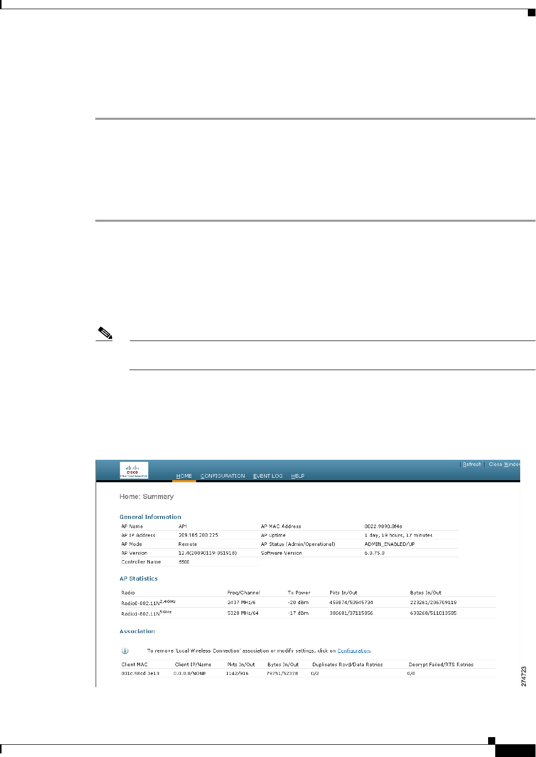
Step 4 On the OfficeExtend Access Point Welcome page, click Enter. The OfficeExtend Access Point Home
page appears (see Figure 8-40).
Figure 8-40 OfficeExtend Access Point Home Page
8-86
Cisco Wireless LAN Controller Configuration Guide
OL-21524-02
Chapter 8 Controlling Lightweight Access Points
OfficeExtend Access Points
This page shows the access point name, IP address, MAC address, software version, status, channel,
transmit power, and client traffic.
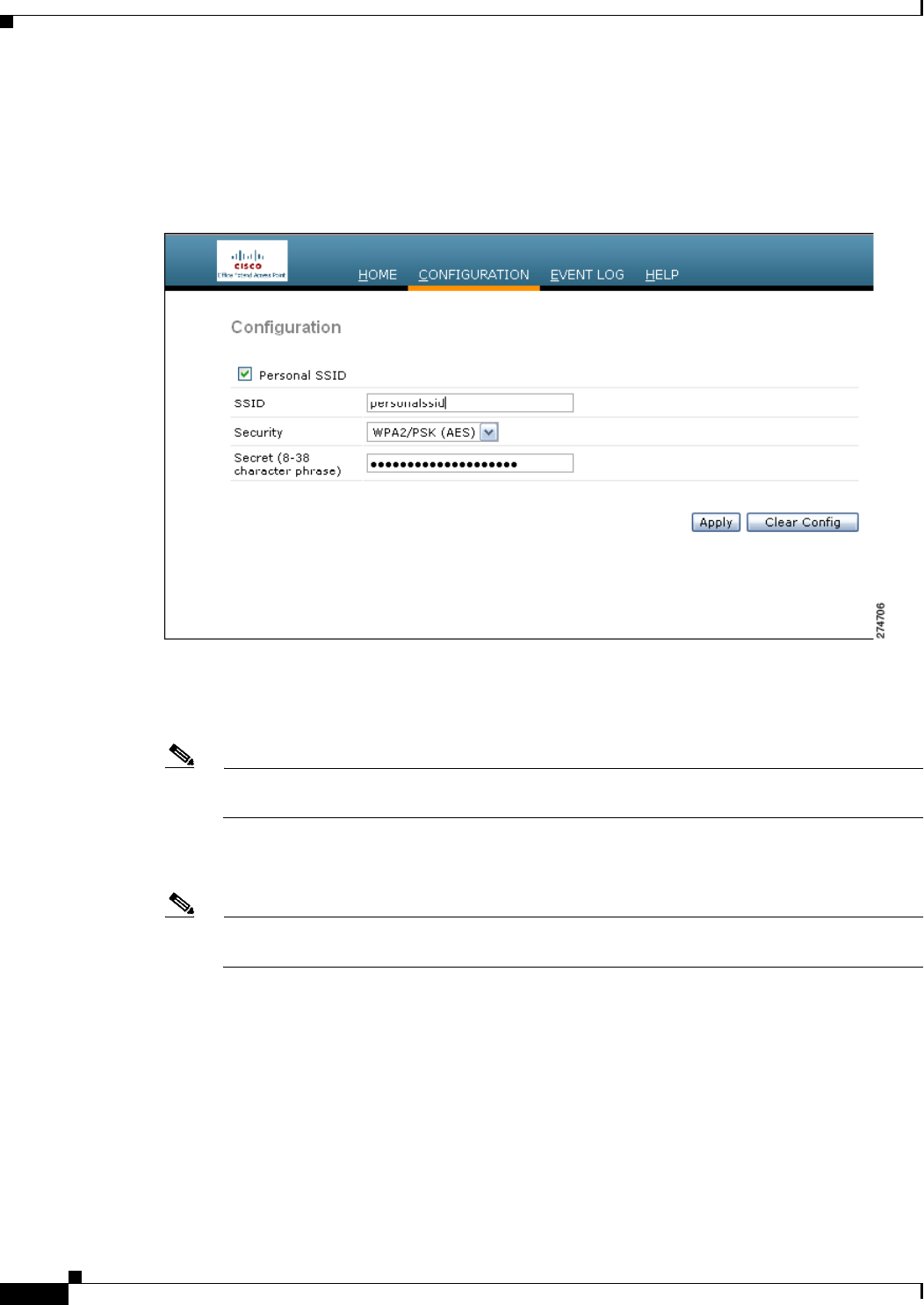
Step 5 Choose Configuration to open the Configuration page (see Figure 8-41).
Figure 8-41 OfficeExtend Access Point Configuration Page
Step 6 Select the Personal SSID check box to enable this wireless connection. The default value is disabled.
Step 7 In the SSID text box, enter the personal SSID that you want to assign to this access point. This SSID is
locally switched.
Note A controller with an OfficeExtend access point publishes only up to 15 WLANs to each
connected access point because it reserves one WLAN for the personal SSID.
Step 8 From the Security drop-down list, choose Open, WPA2/PSK (AES), or 104 bit WEP to set the security
type to be used by this access point.
Note If you choose WPA2/PSK (AES), make sure that the client is configured for WPA2/PSK and
AES encryption.
Step 9 If you chose WPA2/PSK (AES) in Step 8, enter an 8- to 38-character WPA2 passphrase in the Secret text
box. If you chose 104 bit WEP, enter a 13-character ASCII key in the Key text box.
Step 10 Click Apply to commit your changes.

8-87
Cisco Wireless LAN Controller Configuration Guide
OL-21524-02
Chapter 8 Controlling Lightweight Access Points
OfficeExtend Access Points
Note If you want to use the OfficeExtend access point for another application, you can clear this
configuration and return the access point to the factory-default settings by clicking Clear
Config. You can also clear the access point’s configuration from the controller CLI by entering
the clear ap config Cisco_AP command.
Viewing OfficeExtend Access Point Statistics
Use these commands to view information about the OfficeExtend access points on your network:
• See a list of all OfficeExtend access points by entering this command:
show hreap office-extend summary
Information similar to the following appears:
Summary of OfficeExtend AP
AP Name Ethernet MAC Encryption Join-Mode Join-Time
----------- ------------------ ----------- ----------- ----------------------------
AP1130 00:22:90:e3:37:70 Enabled Latency Sun Jan 4 21:46:07 2009
AP1140 01:40:91:b5:31:70 Enabled Latency Sat Jan 3 19:30:25 2009
• See the link delay for OfficeExtend access points by entering this command:
show hreap office-extend latency
Information similar to the following appears:
Summary of OfficeExtend AP link latency
AP Name Status Current Maximum Minimum
--------- ----------- ---------- --------- ---------
AP1130 Enabled 15 ms 45 ms 12 ms
AP1140 Enabled 14 ms 179 ms 12 ms
• See the encryption state of all access points or a specific access point by entering this command:
show ap link-encryption {all | Cisco_AP}
Information similar to the following appears:
Encryption Dnstream Upstream Last
AP Name State Count Count Update
-------------- ---------- -------- -------- --------
AP1130 En 112 1303 23:49
AP1140 En 232 2146 23:49
auth err: 198 replay err: 0
AP1250 En 0 0 Never
AP1240 En 6191 15011 22:13
This command also shows authentication errors, which track the number of integrity check failures,
and replay errors, which track the number of times that the access point receives the same packet.
See the data plane status for all access points or a specific access point by entering this command:
show ap data-plane {all | Cisco_AP}
Information similar to the following appears:
Min Data Data Max Data Last
AP Name Round Trip Round Trip Round Trip Update
---------------- -------------- -------------- -------------- ---------
AP1130 0.012s 0.014s 0.020s 13:46:23
8-88
Cisco Wireless LAN Controller Configuration Guide
OL-21524-02
Chapter 8 Controlling Lightweight Access Points
Cisco Workgroup Bridges
AP1140 0.012s 0.017s 0.111s 13:46:46
• See the join statistics for the OfficeExtend access points by entering the “Using the CLI to View
Access Point Join Information” section on page 8-58.
Troubleshooting OfficeExtend Access Points
If you experience any problems with OfficeExtend access points, see the Appendix D.
Cisco Workgroup Bridges
A workgroup bridge (WGB) is a mode that can be configured on an autonomous IOS access point to
provide wireless connectivity to a lightweight access point on behalf of clients that are connected by
Ethernet to the WGB access point. A WGB connects a wired network over a single wireless segment by
learning the MAC addresses of its wired clients on the Ethernet interface and reporting them to the
lightweight access point using Internet Access Point Protocol (IAPP) messaging. The WGB provides
wireless access connectivity to wired clients by establishing a single wireless connection to the
lightweight access point. The lightweight access point treats the WGB as a wireless client. See the
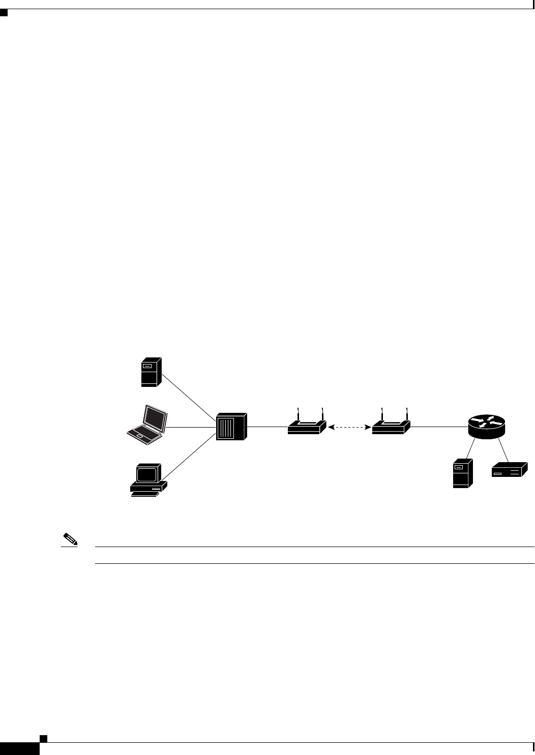
example in Figure 8-42.
Figure 8-42 WGB Example
Note If the lightweight access point fails, the WGB attempts to associate to another access point.
Guidelines for Using WGBs
Follow these guidelines for using WGBs on your network:
• The WGB can be any autonomous access point that supports the workgroup bridge mode and is
running Cisco IOS Release 12.4(3g)JA or later releases (on 32-MB access points) or Cisco IOS
Release 12.3(8)JEB or later releases (on 16-MB access points). These access points include the
AP1120, AP1121, AP1130, AP1231, AP1240, and AP1310. Cisco IOS releases prior to 12.4(3g)JA
and 12.3(8)JEB are not supported.
Wired
clients
Controller
Access point
WGB
Hub
DHCP/ACS
/TFTB/FTP
Switch

8-89
Cisco Wireless LAN Controller Configuration Guide
OL-21524-02
Chapter 8 Controlling Lightweight Access Points
Cisco Workgroup Bridges
Note If your access point has two radios, you can configure only one for workgroup bridge mode.
This radio is used to connect to the lightweight access point. We recommend that you disable
the second radio.
Enable the workgroup bridge mode on the WGB as follows:
–
On the WGB access point GUI, choose Workgroup Bridge for the role in radio network on the
Settings > Network Interfaces page.
–
On the WGB access point CLI, enter the station-role workgroup-bridge command.
Note See the sample WGB access point configuration in the “Sample WGB Configuration”
section on page 8-90.
• The WGB can associate only to lightweight access points.
• Only WGBs in client mode (which is the default value) are supported. Those WGBs in infrastructure
mode are not supported. Perform one of the following to enable client mode on the WGB:
–
On the WGB access point GUI, choose Disabled for the Reliable Multicast to WGB parameter.
–
On the WGB access point CLI, enter the no infrastructure client command.
Note VLANs are not supported for use with WGBs.
Note See the sample WGB access point configuration in the “Sample WGB Configuration”
section on page 8-90.
• These features are supported for use with a WGB:
–
Guest N+1 redundancy
–
Local EAP
–
Open, WEP 40, WEP 128, CKIP, WPA+TKIP, WPA2+AES, LEAP, EAP-FAST, and EAP-TLS
authentication modes
• These features are not supported for use with a WGB:
–
Cisco Centralized Key Management (CCKM)
–
Hybrid REAP
–
Idle timeout
–
Web authentication
Note If a WGB associates to a web-authentication WLAN, the WGB is added to the exclusion
list, and all of the WGB wired clients are deleted.
• The WGB supports a maximum of 20 wired clients. If you have more than 20 wired clients, use a
bridge or another device.

8-90
Cisco Wireless LAN Controller Configuration Guide
OL-21524-02
Chapter 8 Controlling Lightweight Access Points
Cisco Workgroup Bridges
• Wired clients connected to the WGB are not authenticated for security. Instead, the WGB is
authenticated against the access point to which it associates. Therefore, we recommend that you
physically secure the wired side of the WGB.
• With Layer 3 roaming, if you plug a wired client into the WGB network after the WGB has roamed
to another controller (for example, to a foreign controller), the wired client’s IP address displays
only on the anchor controller, not on the foreign controller.
• If a wired client does not send traffic for an extended period of time, the WGB removes the client
from its bridge table, even if traffic is continuously being sent to the wired client. As a result, the
traffic flow to the wired client fails. To avoid the traffic loss, prevent the wired client from being
removed from the bridge table by configuring the aging-out timer on the WGB to a large value using
the following Cisco IOS commands on the WGB:
configure terminal
bridge bridge-group-number aging-time seconds
exit
end
where bridge-group-number is a value between 1 and 255, and seconds is a value between 10 and
1,000,000 seconds. We recommend configuring the seconds parameter to a value greater than the
wired client’s idle period.
• When you delete a WGB record from the controller, all of the WGB wired clients’ records are also
deleted.
• Wired clients connected to a WGB inherit the WGB’s QoS and AAA override attributes.
• These features are not supported for wired clients connected to a WGB:
–
MAC filtering
–
Link tests
–
Idle timeout
• To enable the WGB to communicate with the lightweight access point, create a WLAN and make
sure that Aironet IE is enabled.
Sample WGB Configuration
A sample configuration of a WGB access point using static WEP with a 40-bit WEP key is as follows:
ap# configure terminal
Enter configuration commands, one per line. End with CNTL/Z.
ap(config)# dot11 ssid WGB_with_static_WEP
ap(config-ssid)# authentication open
ap(config-ssid)# guest-mode
ap(config-ssid)# exit
ap(config)# interface dot11Radio 0
ap(config)# station-role workgroup-bridge
ap(config-if)# encry mode wep 40
ap(config-if)# encry key 1 size 40 0 1234567890
ap(config-if)# ssid WGB_with_static_WEP
ap(config-if)# end
Verify that the WGB is associated to an access point by entering this command on the WGB:
show dot11 association
Information similar to the following appears:
ap# show dot11 associations
8-91
Cisco Wireless LAN Controller Configuration Guide
OL-21524-02
Chapter 8 Controlling Lightweight Access Points
Cisco Workgroup Bridges
802.11 Client Stations on Dot11Radio0:
SSID [FCVTESTING] :
MAC Address IP address Device Name Parent State
000b.8581.6aee 10.11.12.1 WGB-client map1 - Assoc
ap#
Using the GUI to View the Status of Workgroup Bridges
To view the status of WGBs on your network using the controller GUI, follow these steps:
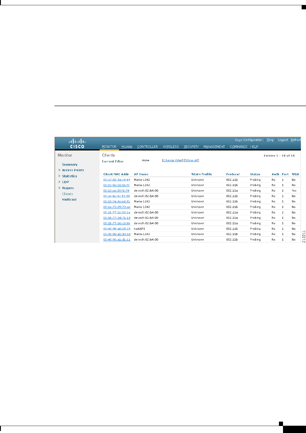
Step 1 Choose Monitor > Clients to open the Clients page (see Figure 8-43).
Figure 8-43 Clients Page
The WGB text box on the right side of the page indicates whether any of the clients on your network are
workgroup bridges.
Step 2 Click the MAC address of the desired client. The Clients > Detail page appears (see Figure 8-44).
8-92
Cisco Wireless LAN Controller Configuration Guide
OL-21524-02
Chapter 8 Controlling Lightweight Access Points
Cisco Workgroup Bridges
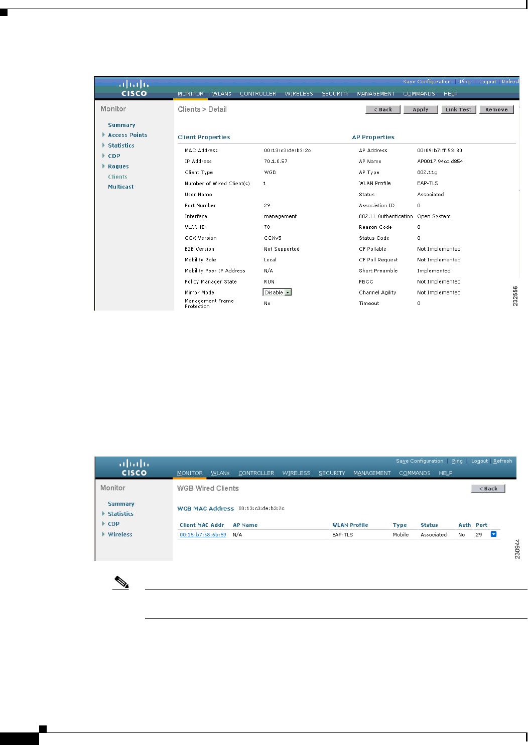
Figure 8-44 Clients > Detail Page
The Client Type text box under Client Properties shows “WGB” if this client is a workgroup bridge, and
the Number of Wired Client(s) text box shows the number of wired clients that are connected to this
WGB.
Step 3 See the details of any wired clients that are connected to a particular WGB as follows:
a. Click Back on the Clients > Detail page to return to the Clients page.
b. Hover your cursor over the blue drop-down arrow for the desired WGB and choose Show Wired
Clients. The WGB Wired Clients page appears (see Figure 8-45).
Figure 8-45 WGB Wired Clients Page
Note If you want to disable or remove a particular client, hover your cursor over the blue
drop-down arrow for the desired client and choose Remove or Disable, respectively.
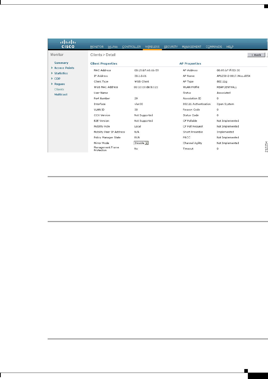
c. Click the MAC address of the desired client to see more details for this particular client. The Clients
> Detail page appears (see Figure 8-46).
8-93
Cisco Wireless LAN Controller Configuration Guide
OL-21524-02
Chapter 8 Controlling Lightweight Access Points
Cisco Workgroup Bridges
Figure 8-46 Clients > Detail Page
The Client Type text box under Client Properties shows “WGB Client,” and the rest of the text boxes
on this page provide additional information for this client.
Using the CLI to View the Status of Workgroup Bridges
To see the status of WGBs on your network using the controller CLI, follow these steps:
Step 1 See any WGBs on your network by entering this command:
show wgb summary
Information similar to the following appears:
Number of WGBs................................... 1
MAC Address IP Address AP Name Status WLAN Auth Protocol Clients
----------------- ---------- -------- ------ ---- ----- --------- --------
00:0d:ed:dd:25:82 10.24.8.73 a1 Assoc 3 Yes 802.11b 1
Step 2 See the details of any wired clients that are connected to a particular WGB by entering this command:
show wgb detail wgb_mac_address
Information similar to the following appears:
Number of wired client(s): 1
MAC Address IP Address AP Name Mobility WLAN Auth
------------------- ---------- -------- --------- ----- -----
00:0d:60:fc:d5:0b 10.24.8.75 a1 Local 3 Yes

8-94
Cisco Wireless LAN Controller Configuration Guide
OL-21524-02
Chapter 8 Controlling Lightweight Access Points
Non-Cisco Workgroup Bridges
Using the CLI to Debug WGB Issues
Use these commands if you experience any problems with the WGB:
• Enable debugging for IAPP messages, errors, and packets by entering these commands:
–
debug iapp all enable—Enables debugging for IAPP messages.
–
debug iapp error enable—Enables debugging for IAPP error events.
–
debug iapp packet enable—Enables debugging for IAPP packets.
• Debug an roaming issue by entering this command:
debug mobility handoff enable
• Debug an IP assignment issue when DHCP is used by entering these commands:
–
debug dhcp message enable
–
debug dhcp packet enable
• Debug an IP assignment issue when static IP is used by entering these commands:
–
debug dot11 mobile enable
–
debug dot11 state enable
Non-Cisco Workgroup Bridges
When a Cisco workgroup bridge (WGB) is used, the WGB informs the access points of all the clients
that it is associated with. The controller is aware of the clients associated with the access point. When
non-Cisco WGBs are used, the controller has no information about the IP address of the clients on the
wired segment behind the WGB. Without this information, the controller drops the following types of
messages:
• ARP REQ from the distribution system for the WGB client
• ARP RPLY from the WGB client
• DHCP REQ from the WGB client
• DHCP RPLY for the WGB client
Starting in release 7.0.116.0, the controller can accommodate non-Cisco WGBs so that the controller can
forward ARP, DHCP, and data traffic to and from the wired clients behind workgroup bridges by
enabling the passive client feature. To configure your controller to work with non-Cisco WGBs, you
must enable the passive client feature so that all traffic from the wired clients is routed through the WGB
to the access point. All traffic from the wired clients is routed through the work group bridge to the
access point. To know more about how to configure the controller to use passive clients, see the
“Configuring Passive Client” section on page 74.
The following restrictions apply to non-Cisco WGB:
• Only Layer 2 roaming is supported for WGB devices.
• Layer 3 security (web authentication) is not support for WGB clients.
• Visibility of wired hosts behind a WGB on a controller is not supported because the non-Cisco WGB
device performs MAC hiding. Cisco WGB supports IAPP.
• ARP poisoning detection does not work on a WLAN when the flag is enabled.
• VLAN select is not supported for WGB clients.

8-95
Cisco Wireless LAN Controller Configuration Guide
OL-21524-02
Chapter 8 Controlling Lightweight Access Points
Configuring Backup Controllers
• Some third-party WGBs need to operate in non-DHCP relay mode. If problems occur with the
DHCP assignment on devices behind the non-Cisco WGB, use the following commands:
–
config dhcp proxy disable
–
config dhcp proxy disable bootp-broadcast disable
The default state is DHCP proxy enabled. The best combination depends on the third-party
characteristics and configuration.
• When a WGB wired client leaves a multicast group, the downstream multicast traffic to other WGB
wired clients is interrupted briefly.
• If you have clients that use PC virtualization software like VMware, you must enable this feature.
Note We have tested multiple third-party devices for compatibility, but cannot ensure that all non-Cisco
devices will work. Support for any interaction or configuration details on the third-party device should
be discussed with the device manufacturer.
Notes About Some non-Cisco WGBs
Note You must enable the passive client functionality for all non Cisco workgroup bridges. For more
information, see “Configuring Passive Client” section on page 74.
You might need to use the following commands to configure DHCP on clients:
• Disable DHCP proxy by using the config dhcp proxy disable command.
• Enable DHCP boot broadcast by using the tconfig dhcp proxy disable bootp-broadcast enable
command.
Configuring Backup Controllers
A single controller at a centralized location can act as a backup for access points when they lose
connectivity with the primary controller in the local region. Centralized and regional controllers do not
need to be in the same mobility group. In controller software release 4.2 or later releases, you can specify
a primary, secondary, and tertiary controller for specific access points in your network. Using the
controller GUI or CLI, you can specify the IP addresses of the backup controllers, which allows the
access points to fail over to controllers outside of the mobility group.
In controller software release 5.0 or later releases, you can also configure primary and secondary backup
controllers (which are used if primary, secondary, or tertiary controllers are not specified or are not
responsive) for all access points connected to the controller as well as various timers, including heartbeat
timers and discovery request timers. To reduce the controller failure detection time, you can configure
the fast heartbeat interval (between the controller and the access point) with a smaller timeout value.
When the fast heartbeat timer expires (at every heartbeat interval), the access point determines if any
data packets have been received from the controller within the last interval. If no packets have been
received, the access point sends a fast echo request to the controller.
Note You can configure the fast heartbeat timer only for access points in local and hybrid-REAP modes.

8-96
Cisco Wireless LAN Controller Configuration Guide
OL-21524-02
Chapter 8 Controlling Lightweight Access Points
Configuring Backup Controllers
The access point maintains a list of backup controllers and periodically sends primary discovery requests
to each entry on the list. When the access point receives a new discovery response from a controller, the
backup controller list is updated. Any controller that fails to respond to two consecutive primary
discovery requests is removed from the list. If the access point’s local controller fails, it chooses an
available controller from the backup controller list in this order: primary, secondary, tertiary, primary
backup, and secondary backup. The access point waits for a discovery response from the first available
controller in the backup list and joins the controller if it receives a response within the time configured
for the primary discovery request timer. If the time limit is reached, the access point assumes that the
controller cannot be joined and waits for a discovery response from the next available controller in the
list.
Note When an access point’s primary controller comes back online, the access point disassociates from the
backup controller and reconnects to its primary controller. The access point falls back to its primary
controller and not to any secondary controller for which it is configured. For example, if an access point
is configured with primary, secondary, and tertiary controllers, it fails over to the tertiary controller when
the primary and secondary controllers become unresponsive and waits for the primary controller to come
back online so that it can fall back to the primary controller. The access point does not fall back from the
tertiary controller to the secondary controller if the secondary controller comes back online; it stays
connected to the tertiary controller until the primary controller comes back up.
Note If you inadvertently configure a controller that is running software release 5.2 or later releases with a
failover controller that is running a different software release (such as 4.2, 5.0, or 5.1), the access point
might take a long time to join the failover controller because the access point starts the discovery process
in CAPWAP and then changes to LWAPP discovery.
Using the GUI to Configure Backup Controllers
To configure primary, secondary, and tertiary controllers for a specific access point and to configure
primary and secondary backup controllers for all access points using the controller GUI, follow these
steps:
Step 1 Choose Wireless > Access Points > Global Configuration to open the Global Configuration page (see
Figure 8-47).
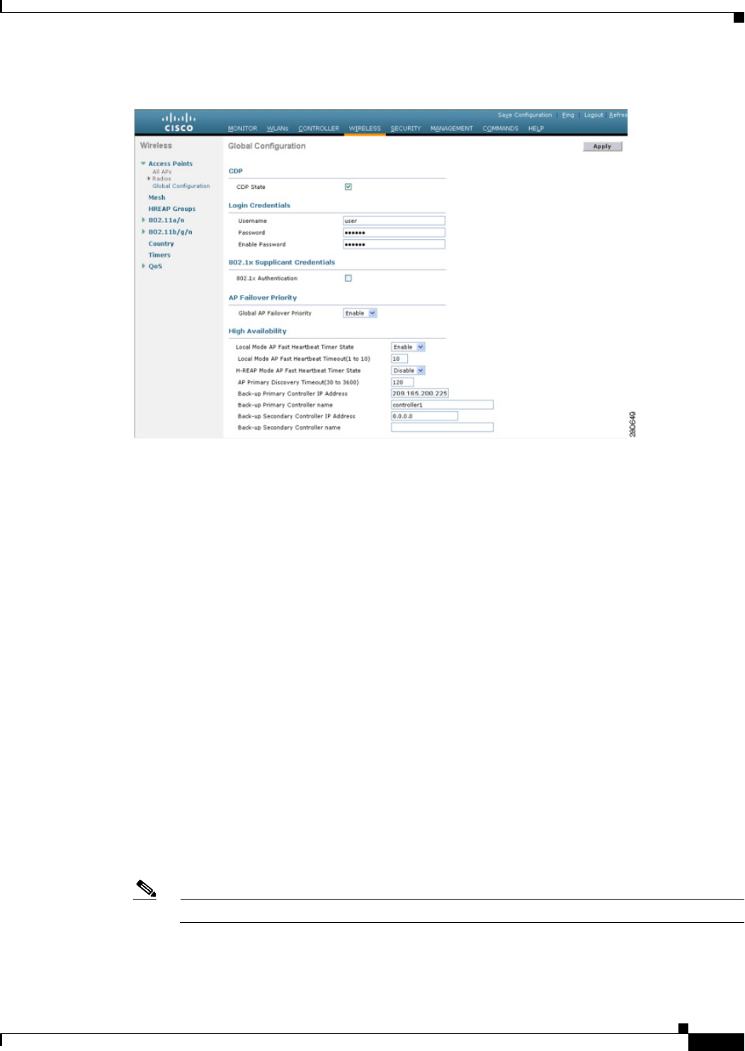
8-97
Cisco Wireless LAN Controller Configuration Guide
OL-21524-02
Chapter 8 Controlling Lightweight Access Points
Configuring Backup Controllers
Figure 8-47 Global Configuration Page
Step 2 From the Local Mode AP Fast Heartbeat Timer State drop-down list, choose Enable to enable the fast
heartbeat timer for access points in local mode or choose Disable to disable this timer. The default value
is Disable.
Step 3 If you chose Enable in Step 2, enter a number between 1 and 10 seconds (inclusive) in the Local Mode
AP Fast Heartbeat Timeout text box to configure the fast heartbeat timer for access points in local mode.
Specifying a small heartbeat interval reduces the amount of time it takes to detect a controller failure.
The default value is 0 seconds, which disables the timer.
Step 4 From the H-REAP Mode AP Fast Heartbeat Timer State drop-down list, choose Enable to enable the
fast heartbeat timer for hybrid-REAP access points or choose Disable to disable this timer. The default
value is Disable.
Step 5 If you chose Enable in Step 4, enter a value between 1 and 10 seconds (inclusive) in the H-REAP Mode
AP Fast Heartbeat Timeout text box to configure the fast heartbeat timer for hybrid-REAP access points.
Specifying a small heartbeat interval reduces the amount of time it takes to detect a controller failure.
The default value is 0 seconds, which disables the timer.
Step 6 In the AP Primary Discovery Timeout text box, a value between 30 and 3600 seconds (inclusive) to
configure the access point primary discovery request timer. The default value is 120 seconds.
Step 7 If you want to specify a primary backup controller for all access points, enter the IP address of the
primary backup controller in the Back-up Primary Controller IP Address text box and the name of the
controller in the Back-up Primary Controller Name text box.
Note The default value for the IP address is 0.0.0.0, which disables the primary backup controller.
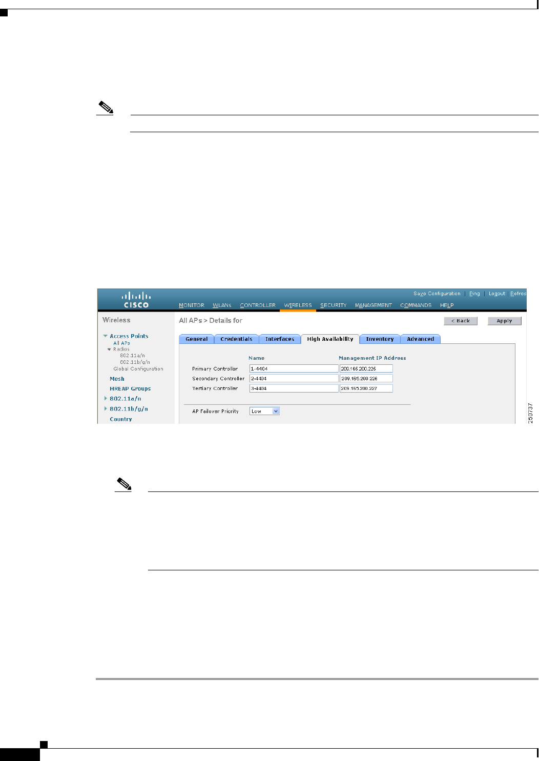
8-98
Cisco Wireless LAN Controller Configuration Guide
OL-21524-02
Chapter 8 Controlling Lightweight Access Points
Configuring Backup Controllers
Step 8 If you want to specify a secondary backup controller for all access points, enter the IP address of the
secondary backup controller in the Back-up Secondary Controller IP Address text box and the name of
the controller in the Back-up Secondary Controller Name text box.
Note The default value for the IP address is 0.0.0.0, which disables the secondary backup controller.
Step 9 Click Apply to commit your changes.
Step 10 Configure primary, secondary, and tertiary backup controllers for a specific access point as follows:
a. Choose Access Points > All APs to open the All APs page.
b. Click the name of the access point for which you want to configure primary, secondary, and tertiary
backup controllers.
c. Choose the High Availability tab to open the All APs > Details for (High Availability) page (see
Figure 8-48).
Figure 8-48 All APs > Details for (High Availability) Page
d. If desired, enter the name and IP address of the primary controller for this access point in the
Primary Controller text boxes.
Note Entering an IP address for the backup controller is optional in this step and the next two
steps. If the backup controller is outside the mobility group to which the access point is
connected (the primary controller), then you need to provide the IP address of the primary,
secondary, or tertiary controller, respectively. The controller name and IP address must
belong to the same primary, secondary, or tertiary controller. Otherwise, the access point
cannot join the backup controller.
e. If desired, enter the name and IP address of the secondary controller for this access point in the
Secondary Controller text boxes.
f. If desired, enter the name and IP address of the tertiary controller for this access point in the Tertiary
Controller text boxes.
g. Click Apply to commit your changes.
Step 11 Click Save Configuration to save your changes.

8-99
Cisco Wireless LAN Controller Configuration Guide
OL-21524-02
Chapter 8 Controlling Lightweight Access Points
Configuring Backup Controllers
Using the CLI to Configure Backup Controllers
To configure primary, secondary, and tertiary controllers for a specific access point and to configure
primary and secondary backup controllers for all access points using the controller CLI, follow these
steps:
Step 1 Configure a primary controller for a specific access point by entering this command:
config ap primary-base controller_name Cisco_AP [controller_ip_address]
Note The controller_ip_address parameter in this command and the next two commands is optional.
If the backup controller is outside the mobility group to which the access point is connected (the
primary controller), then you need to provide the IP address of the primary, secondary, or tertiary
controller, respectively. In each command, the controller_name and controller_ip_address must
belong to the same primary, secondary, or tertiary controller. Otherwise, the access point cannot
join the backup controller.
Step 2 Configure a secondary controller for a specific access point by entering this command:
config ap secondary-base controller_name Cisco_AP [controller_ip_address]
Step 3 Configure a tertiary controller for a specific access point by entering this command:
config ap tertiary-base controller_name Cisco_AP [controller_ip_address]
Step 4 Configure a primary backup controller for all access points by entering this command:
config advanced backup-controller primary backup_controller_name backup_controller_ip_address
Step 5 Configure a secondary backup controller for all access points by entering this command:
config advanced backup-controller secondary backup_controller_name
backup_controller_ip_address
Note To delete a primary or secondary backup controller entry, enter 0.0.0.0 for the controller IP
address.
Step 6 Enable or disable the fast heartbeat timer for local or hybrid-REAP access points by entering this
command:
config advanced timers ap-fast-heartbeat {local | hreap | all} {enable | disable} interval
where all is both local and hybrid-REAP access points, and interval is a value between 1 and 10 seconds
(inclusive). Specifying a small heartbeat interval reduces the amount of time that it takes to detect a
controller failure. The default value is disabled.Configure the access point heartbeat timer by entering
this command:
config advanced timers ap-heartbeat-timeout interval
where interval is a value between 1 and 30 seconds (inclusive). This value should be at least three times
larger than the fast heartbeat timer. The default value is 30 seconds.
Caution Do not enable the fast heartbeat timer with the high latency link. If you have to enable the fast heartbeat
timer, the timer value must be greater than the latency.
Step 7 Configure the access point primary discovery request timer by entering this command:

8-100
Cisco Wireless LAN Controller Configuration Guide
OL-21524-02
Chapter 8 Controlling Lightweight Access Points
Configuring Backup Controllers
config advanced timers ap-primary-discovery-timeout interval
where interval is a value between 30 and 3600 seconds. The default value is 120 seconds.
Step 8 Configure the access point discovery timer by entering this command:
config advanced timers ap-discovery-timeout interval
where interval is a value between 1 and 10 seconds (inclusive). The default value is 10 seconds.
Step 9 Configure the 802.11 authentication response timer by entering this command:
config advanced timers auth-timeout interval
where interval is a value between 10 and 600 seconds (inclusive). The default value is 10 seconds.
Step 10 Save your changes by entering this command:
save config
Step 11 See an access point’s configuration by entering these commands:
• show ap config general Cisco_AP
• show advanced backup-controller
• show advanced timers
Information similar to the following appears for the show ap config general Cisco_AP command:
Cisco AP Identifier.............................. 1
Cisco AP Name.................................... AP5
Country code..................................... US - United States
Regulatory Domain allowed by Country............. 802.11bg:-AB 802.11a:-AB
AP Country code.................................. US - United States
AP Regulatory Domain............................. 802.11bg:-A 802.11a:-N
Switch Port Number .............................. 1
MAC Address...................................... 00:13:80:60:48:3e
IP Address Configuration......................... DHCP
IP Address....................................... 1.100.163.133
...
Primary Cisco Switch Name........................ 1-4404
Primary Cisco Switch IP Address.................. 2.2.2.2
Secondary Cisco Switch Name...................... 1-4404
Secondary Cisco Switch IP Address................ 2.2.2.2
Tertiary Cisco Switch Name....................... 2-4404
Tertiary Cisco Switch IP Address................. 1.1.1.4
...
Information similar to the following appears for the show advanced backup-controller command:
AP primary Backup Controller .................... controller1 10.10.10.10
AP secondary Backup Controller ............... 0.0.0.0
Information similar to the following appears for the show advanced timers command:
Authentication Response Timeout (seconds)........ 10
Rogue Entry Timeout (seconds).................... 1300
AP Heart Beat Timeout (seconds).................. 30
AP Discovery Timeout (seconds)................... 10
AP Local mode Fast Heartbeat (seconds)........... 10 (enable)
AP Hreap mode Fast Heartbeat (seconds)........... disable
AP Primary Discovery Timeout (seconds)........... 120
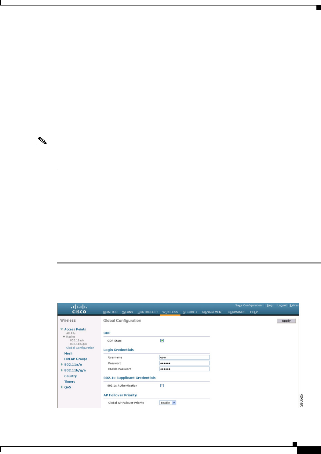
8-101
Cisco Wireless LAN Controller Configuration Guide
OL-21524-02
Chapter 8 Controlling Lightweight Access Points
Configuring Failover Priority for Access Points
Configuring Failover Priority for Access Points
Each controller has a defined number of communication ports for access points. When multiple
controllers with unused access point ports are deployed on the same network and one controller fails, the
dropped access points automatically poll for unused controller ports and associate with them.
In controller software releases prior to 5.1, the backup controllers accept association requests in the
order that the requests are received until all the ports are in use. As a result, the probability of an access
point finding an open port on a backup controller is determined by where in the association request queue
it is after the controller failure.
In controller software release 5.1 or later releases, you can configure your wireless network so that the
backup controller recognizes a join request from a higher-priority access point and if necessary
disassociates a lower-priority access point as a means to provide an available port.
Note Failover priority is not in effect during the regular operation of your wireless network. It takes effect only
if there are more association requests after a controller failure than there are available backup controller
ports.
To configure this feature, you must enable failover priority on your network and assign priorities to the
individual access points. You can do so using the controller GUI or CLI.
By default, all access points are set to priority level 1, which is the lowest priority level. Therefore, you
need to assign a priority level only to those access points that warrant a higher priority.
Using the GUI to Configure Failover Priority for Access Points
To configure failover priority for access points that join the controller using the controller GUI, follow
these steps:
Step 1 Choose Wireless > Access Points > Global Configuration to open the Global Configuration page
(see Figure 8-49).
Figure 8-49 Global Configuration Page
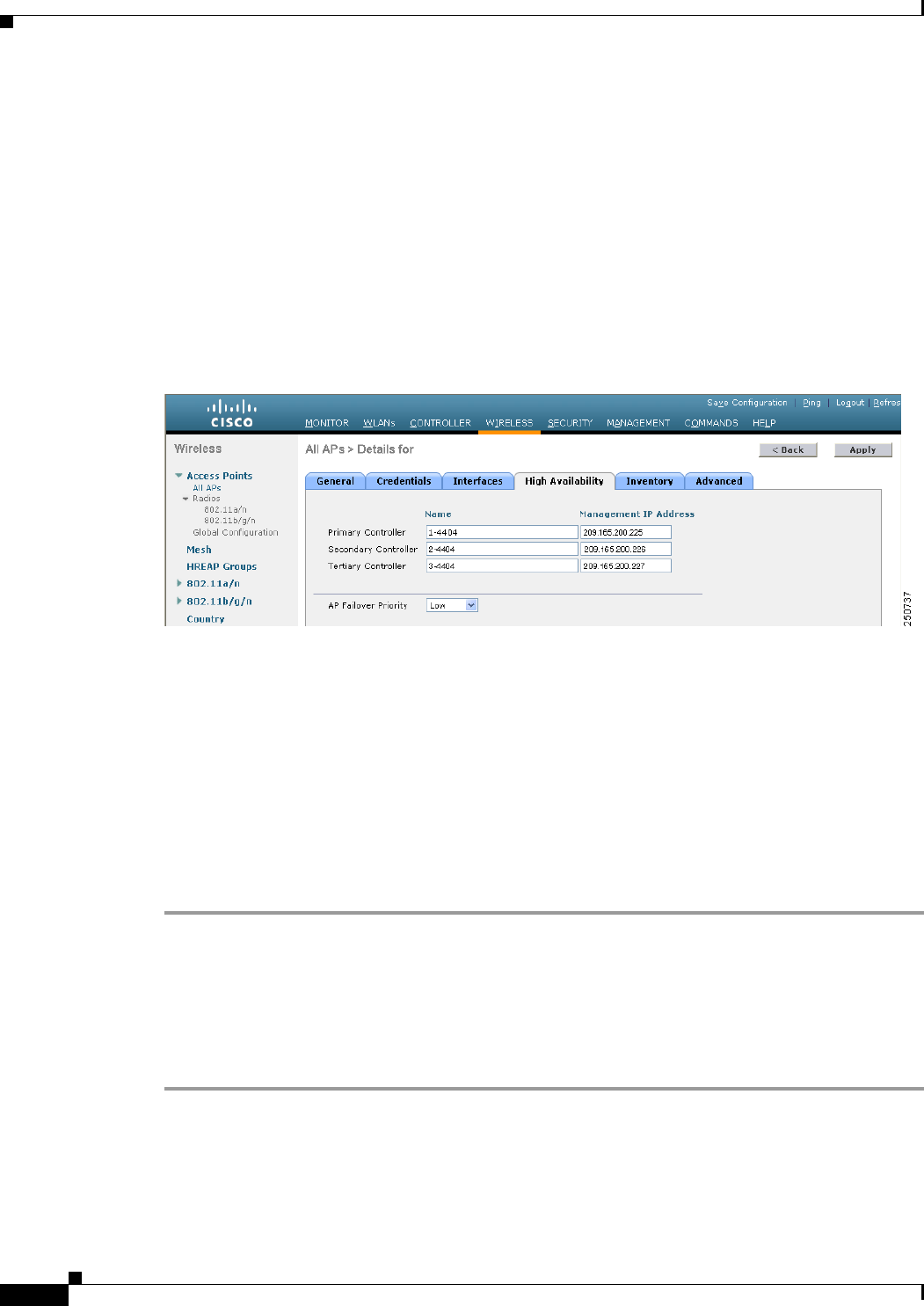
8-102
Cisco Wireless LAN Controller Configuration Guide
OL-21524-02
Chapter 8 Controlling Lightweight Access Points
Configuring Failover Priority for Access Points
Step 2 From the Global AP Failover Priority drop-down list, choose Enable to enable access point failover
priority or choose Disable to disable this feature and turn off any access point priority assignments. The
default value is Disable.
Step 3 Click Apply to commit your changes.
Step 4 Click Save Configuration to save your changes.
Step 5 Choose Wireless > Access Points > All APs to open the All APs page.
Step 6 Click the name of the access point for which you want to configure failover priority.
Step 7 Choose the High Availability tab. The All APs > Details for (High Availability) page appears (see
Figure 8-50).
Figure 8-50 All APs > Details for (High Availability) Page
Step 8 From the AP Failover Priority drop-down list, choose one of the following options to specify the priority
of the access point:
• Low—Assigns the access point to the level 1 priority, which is the lowest priority level. This is the
default value.
• Medium—Assigns the access point to the level 2 priority.
• High—Assigns the access point to the level 3 priority.
• Critical—Assigns the access point to the level 4 priority, which is the highest priority level.
Step 9 Click Apply to commit your changes.
Step 10 Click Save Configuration to save your changes.
Using the CLI to Configure Failover Priority for Access Points
To configure failover priority for access points that join the controller using the controller CLI, follow
these steps:
Step 1 Enable or disable access point failover priority by entering this command:
config network ap-priority {enable | disable}
Step 2 Specify the priority of an access point by entering this command:
config ap priority {1 | 2 | 3 | 4} Cisco_AP

8-103
Cisco Wireless LAN Controller Configuration Guide
OL-21524-02
Chapter 8 Controlling Lightweight Access Points
Configuring Access Point Retransmission Interval and Retry Count
where 1 is the lowest priority level and 4 is the highest priority level. The default value is 1.
Step 3 Save your changes by entering this command:
save config
Using the CLI to View Failover Priority Settings
Use these commands to see the failover priority configuration settings on your network:
• Confirm whether access point failover priority is enabled on your network by entering this
command:
show network summary
Information similar to the following appears:
RF-Network Name............................. mrf
Web Mode.................................... Enable
Secure Web Mode............................. Enable
Secure Web Mode Cipher-Option High.......... Disable
Secure Shell (ssh).......................... Enable
Telnet...................................... Enable
Ethernet Multicast Mode..................... Disable
Ethernet Broadcast Mode..................... Disable
IGMP snooping............................... Disabled
IGMP timeout................................ 60 seconds
User Idle Timeout........................... 300 seconds
ARP Idle Timeout............................ 300 seconds
Cisco AP Default Master..................... Disable
AP Join Priority......................... Enabled
...
• See the failover priority for each access point by entering this command:
show ap summary
Information similar to the following appears:
Number of APs.................................... 2
Global AP User Name.............................. user
Global AP Dot1x User Name........................ Not Configured
AP Name Slots AP Model Ethernet MAC Location Port Country Priority
------- ----- ------------------ ----------------- --------- ---- ------- -------
ap:1252 2 AIR-LAP1252AG-A-K9 00:1b:d5:13:39:74 hallway 6 1 US 1
ap:1121 1 AIR-LAP1121G-A-K9 00:1b:d5:a9:ad:08 reception 1 US 3
To see summary of specific access point you can specify the access point name. You can also use
wildcard searches when filtering for access points.
Configuring Access Point Retransmission Interval and Retry
Count
This section describes how to configure the retransmission interval and retry count for an access point
when associating with a controller.

8-104
Cisco Wireless LAN Controller Configuration Guide
OL-21524-02
Chapter 8 Controlling Lightweight Access Points
Configuring Access Point Retransmission Interval and Retry Count
The controller and the access points exchange packets using the CAPWAP reliable transport protocol.
For each request, a response is defined. This response is used to acknowledge the receipt of the request
message. Response messages are not explicitly acknowledged; therefore, if a response message is not
received, the original request message is retransmitted after the retransmit interval. If the request is not
acknowledged after a maximum number of retransmissions, the session is closed and the access points
reassociate with another controller.
You can configure the retransmission intervals and retry count both at a global as well as a specific access
point level. A global configuration applies these configuration parameters to all the access points. That
is, the retransmission interval and the retry count are uniform for all access points. Alternatively, when
you configure the retransmission level and retry count at a specific access point level, the values are
applied to that particular access point. The access point specific configuration has a higher precedence
than the global configuration.
Note Retransmission intervals and the retry count do not apply for mesh access point.
Using the GUI to Configure the Access Point Retransmission Interval and Retry
Count
You can configure the retransmission interval and retry count for all access points globally or a specific
access point.
To configure the controller to set the retransmission interval and retry count globally using the controller
GUI, follow these steps:
Step 1 Choose Wireless > Access Points > Global Configuration.
Step 2 Choose one of the following options under the AP Transmit Config Parameters section:
• AP Retransmit Count—Enter the number of times you want the access point to retransmit the
request to the controller. This parameter can take values between 3 and 8.
• AP Retransmit Interval—Enter the time duration between the retransmission of requests. This
parameter can take values between 2 and 5.
Step 3 Click Apply.
To configure the controller to set retransmission interval and retry count for a specific access point,
follow these steps:
Step 1 Choose Wireless > Access Points > All APs.
Step 2 Click on the AP Name link for the access point on which you want to set the values.
The All APs > Details page appears.
Step 3 Click the Advanced Tab to open the advanced parameters page.
Step 4 Choose one of the following parameters under the AP Transmit Config Parameters section:
• AP Retransmit Count—Enter the number of times that you want the access point to retransmit the
request to the controller. This parameter can take values between 3 and 8.

8-105
Cisco Wireless LAN Controller Configuration Guide
OL-21524-02
Chapter 8 Controlling Lightweight Access Points
Configuring Access Point Retransmission Interval and Retry Count
• AP Retransmit Interval—Enter the time duration between the retransmission of requests. This
parameter can take values between 2 and 5.
Step 5 Click Apply.
Using the CLI to Configure the Access Point Retransmission Interval and Retry
Count
You can configure the retransmission interval and retry count for all access points globally or a specific
access point.
• Configure the retransmission interval and retry count for all access points globally by entering the
this command:
config ap retransmit {interval | count} seconds all
The valid range for the interval parameter is between 3 and 8. The valid range for the count
parameter is between 2 and 5.
• Configure the retransmission interval and retry count for a specific access point, by entering this
command:
config ap retransmit {interval | count} seconds Cisco_AP
The valid range for the interval parameter is between 3 and 8. The valid range for the count
parameter is between 2 and 5.
• See the status of the configured retransmit parameters on all or specific APs by entering this
command:
show ap retransmit all
(Cisco Controller) >show ap retransmit all
Global control packet retransmit interval: 5
Global control packet retransmit count: 6
AP Name Retransmit Interval Retransmit count
------------------ ------------------- -------------------
AP_1131 N/A(Mesh mode) N/A(Mesh mode)
AP_cisco_ 5 4
abhes_1240 5 6
Note Because retransmit and retry values cannot be set for access points in mesh mode, these values
are displayed as N/A (not applicable).
• See the status of the configured retransmit parameters on a specific access point by entering this
command:
show ap retransmit Cisco_AP
(Cisco Controller) >show ap retransmit cisco_AP1
Global control packet retransmit interval: 5
Global control packet retransmit count: 6
AP Name Retransmit Interval Retransmit count
------------------ ------------------- -------------------
cisco_AP1 5 6
(Cisco Controller) >

8-106
Cisco Wireless LAN Controller Configuration Guide
OL-21524-02
Chapter 8 Controlling Lightweight Access Points
Configuring Country Codes
Configuring Country Codes
Controllers and access points are designed for use in many countries with varying regulatory
requirements. The radios within the access points are assigned to a specific regulatory domain at the
factory (such as -E for Europe), but the country code enables you to specify a particular country of
operation (such as FR for France or ES for Spain). Configuring a country code ensures that each radio’s
broadcast frequency bands, interfaces, channels, and transmit power levels are compliant with
country-specific regulations.
Generally, you configure one country code per controller, the one matching the physical location of the
controller and its access points. However, controller software release 4.1 or later releases allows you to
configure up to 20 country codes per controller. This multiple-country support enables you to manage
access points in various countries from a single controller.
Note Although the controller supports different access points in different regulatory domains (countries), it
requires all radios in a single access point to be configured for the same regulatory domain. For example,
you should not configure a Cisco 1231 access point’s 802.11b/g radio for the US (-A) regulatory domain
and its 802.11a radio for the Great Britain (-E) regulatory domain. Otherwise, the controller allows only
one of the access point’s radios to turn on, depending on which regulatory domain you selected for the
access point on the controller. Therefore, make sure that the same country code is configured for both of
the access point’s radios.
For a complete list of country codes supported per product, see
http://tools.cisco.com/cse/prdapp/jsp/externalsearch.do?action=externalsearch&page=EXTERNAL_SE
ARCH or
http://www.cisco.com/en/US/prod/collateral/wireless/ps5679/ps5861/product_data_sheet0900aecd805
37b6a_ps6087_Products_Data_Sheet.html
Guidelines for Configuring Multiple Country Codes
Follow these guidelines when configuring multiple country codes:
• When the multiple-country feature is being used, all controllers that are going to join the same RF
group must be configured with the same set of countries, configured in the same order.
• When multiple countries are configured and the radio resource management (RRM) auto-RF feature
is enabled, the common channels allowed is derived by performing a union (or superset) of the
allowed channels in the countries. The access points are always able to use all legal frequencies, but
noncommon channels can only be assigned manually.
• The access point can only operate on the channels for the countries that they are designed for.
Note If an access point was already set to a higher legal power level or is configured manually,
the power level is limited only by the particular country to which that access point is
assigned.
• The country list configured on the RF group leader determines what channels the members would
operate on. This list is independent of what countries have been configured on the RF group
members.
You can configure country codes through the controller GUI or CLI.
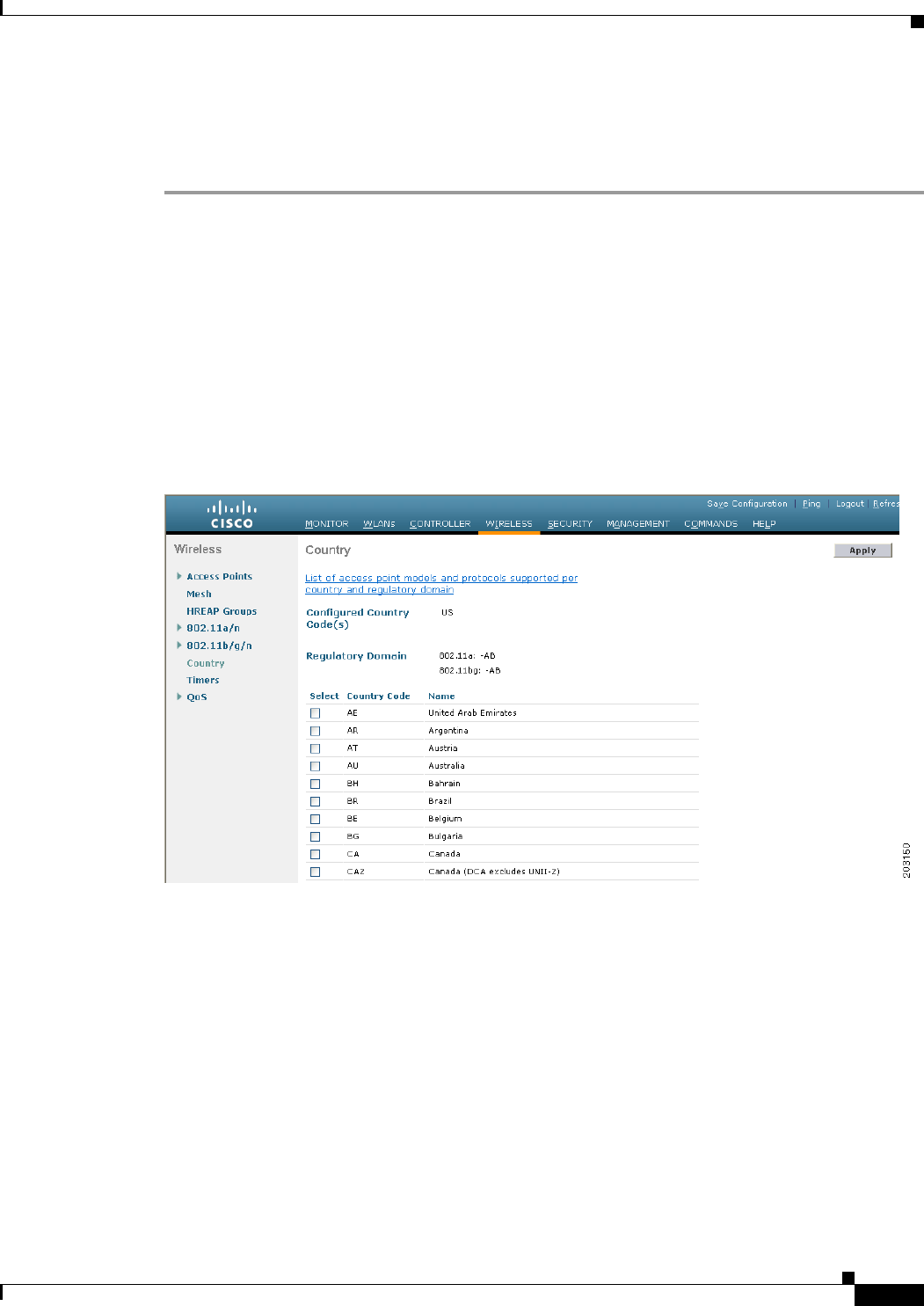
8-107
Cisco Wireless LAN Controller Configuration Guide
OL-21524-02
Chapter 8 Controlling Lightweight Access Points
Configuring Country Codes
Using the GUI to Configure Country Codes
To configure country codes using the controller GUI, follow these steps:
Step 1 Follow these steps to disable the 802.11a and 802.11b/g networks as follows:
a. Choose Wireless> 802.11a/n > Network.
b. Unselect the 802.11a Network Status check box.
c. Click Apply to commit your changes.
d. Choose Wireless > 802.11b/g/n > Network.
e. Unselect the 802.11b/g Network Status check box.
f. Click Apply to commit your changes.
Step 2 Choose Wireless > Country to open the Country page (see Figure 8-51).
Figure 8-51 Country Page
Step 3 Select the check box for each country where your access points are installed. If you selected more than
one check box, a message appears indicating that RRM channels and power levels are limited to common
channels and power levels.
Step 4 Click OK to continue or Cancel to cancel the operation.
Step 5 Click Apply to commit your changes.
If you selected multiple country codes in Step 3, each access point is assigned to a country.
Step 6 See the default country chosen for each access point and choose a different country if necessary as
follows:
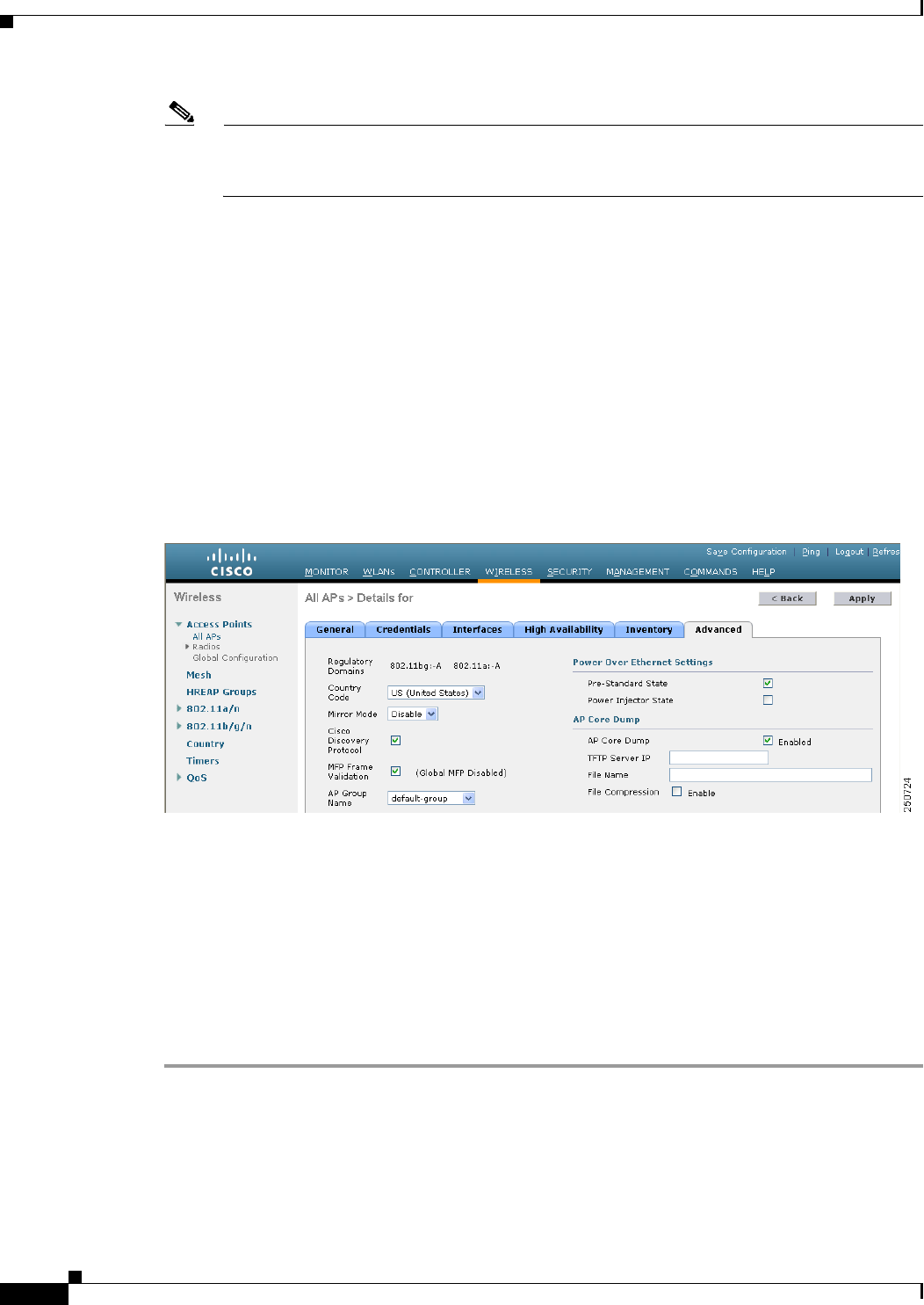
8-108
Cisco Wireless LAN Controller Configuration Guide
OL-21524-02
Chapter 8 Controlling Lightweight Access Points
Configuring Country Codes
Note If you remove a country code from the configuration, any access points currently assigned to the
deleted country reboot and when they rejoin the controller, they get re-assigned to one of the
remaining countries if possible.
a. Perform one of the following:
–
Leave the 802.11a and 802.11b/g networks disabled.
–
Reenable the 802.11a and 802.11b/g networks and then disable only the access points for which
you are configuring a country code. To disable an access point, choose Wireless > Access
Points > All APs, click the link of the desired access point, choose Disable from the Status
drop-down list, and click Apply.
b. Choose Wireless > Access Points > All APs to open the All APs page.
c. Click the link for the desired access point.
d. Choose the Advanced tab to open the All APs > Details for (Advanced) page (see Figure 8-52).
The default country for this access point appears in the Country Code drop-down list.
Figure 8-52 All APs > Details for (Advanced) Page
e. If the access point is installed in a country other than the one shown, choose the correct country from
the drop-down list. The box contains only those country codes that are compatible with the
regulatory domain of at least one of the access point’s radios.
f. Click Apply to commit your changes.
g. Repeat these steps to assign all access points joined to the controller to a specific country.
h. Reenable any access points that you disabled in Step a.
Step 7 Reenable the 802.11a and 802.11b/g networks if you did not enable them in Step 6.
Step 8 Click Save Configuration to save your settings.

8-109
Cisco Wireless LAN Controller Configuration Guide
OL-21524-02
Chapter 8 Controlling Lightweight Access Points
Configuring Country Codes
Using the CLI to Configure Country Codes
To configure country codes using the controller CLI, follow these steps:
Step 1 See a list of all available country codes by entering this command:
show country supported
Step 2 Disable the 802.11a and 802.11b/g networks by entering these commands:
config 802.11a disable network
config 802.11b disable network
Step 3 Configure the country codes for the countries where your access points are installed by entering this
command:
config country code1[,code2,code3,...]
If you are entering more than one country code, separate each by a comma (for example, config country
US,CA,MX). Information similar to the following appears:
Changing country code could reset channel configuration.
If running in RFM One-Time mode, reassign channels after this command.
Check customized APs for valid channel values after this command.
Are you sure you want to continue? (y/n) y
Step 4 Enter Y when prompted to confirm your decision. Information similar to the following appears:
Configured Country............................. Multiple Countries:US,CA,MX
Auto-RF for this country combination is limited to common channels and power.
KEY: * = Channel is legal in this country and may be configured manually.
A = Channel is the Auto-RF default in this country.
. = Channel is not legal in this country.
C = Channel has been configured for use by Auto-RF.
x = Channel is available to be configured for use by Auto-RF.
(-) = Regulatory Domains allowed by this country.
------------:+-+-+-+-+-+-+-+-+-+-+-+-+-+-
802.11BG :
Channels : 1 1 1 1 1
: 1 2 3 4 5 6 7 8 9 0 1 2 3 4
------------:+-+-+-+-+-+-+-+-+-+-+-+-+-+-
US (-AB) : A * * * * A * * * * A . . .
CA (-AB) : A * * * * A * * * * A . . .
MX (-NA) : A * * * * A * * * * A . . .
Auto-RF : C x x x x C x x x x C . . .
------------:+-+-+-+-+-+-+-+-+-+-+-+-+-+-+-+-+-+-+-+-+-+-+-+-+-+-+-+-
802.11A : 1 1 1 1 1 1 1 1 1 1 1 1 1 1 1 1
Channels : 3 3 3 4 4 4 4 4 5 5 6 6 0 0 0 1 1 2 2 2 3 3 4 4 5 5 6 6
--More-- or (q)uit
: 4 6 8 0 2 4 6 8 2 6 0 4 0 4 8 2 6 0 4 8 2 6 0 9 3 7 1 5
------------:+-+-+-+-+-+-+-+-+-+-+-+-+-+-+-+-+-+-+-+-+-+-+-+-+-+-+-+-
US (-AB) : . A . A . A . A A A A A * * * * * . . . * * * A A A A *
CA (-ABN) : . A . A . A . A A A A A * * * * * . . . * * * A A A A *
MX (-N) : . A . A . A . A A A A A . . . . . . . . . . . A A A A *
Auto-RF : . C . C . C . C C C C C . . . . . . . . . . . C C C C x
Step 5 Verify your country code configuration by entering this command:
show country
Step 6 See the list of available channels for the country codes configured on your controller by entering this
command:
show country channels

8-110
Cisco Wireless LAN Controller Configuration Guide
OL-21524-02
Chapter 8 Controlling Lightweight Access Points
Configuring Country Codes
Information similar to the following appears:
Configured Country............................. Multiple Countries:US,CA,MX
Auto-RF for this country combination is limited to common channels and power.
KEY: * = Channel is legal in this country and may be configured manually.
A = Channel is the Auto-RF default in this country.
. = Channel is not legal in this country.
C = Channel has been configured for use by Auto-RF.
x = Channel is available to be configured for use by Auto-RF.
(-) = Regulatory Domains allowed by this country.
------------:+-+-+-+-+-+-+-+-+-+-+-+-+-+-
802.11BG :
Channels : 1 1 1 1 1
: 1 2 3 4 5 6 7 8 9 0 1 2 3 4
------------:+-+-+-+-+-+-+-+-+-+-+-+-+-+-
US (-AB) : A * * * * A * * * * A . . .
CA (-AB) : A * * * * A * * * * A . . .
MX (-NA) : A * * * * A * * * * A . . .
Auto-RF : C x x x x C x x x x C . . .
------------:+-+-+-+-+-+-+-+-+-+-+-+-+-+-+-+-+-+-+-+-+-+-+-+-+-+-+-+-
802.11A : 1 1 1 1 1 1 1 1 1 1 1 1 1 1 1 1
Channels : 3 3 3 4 4 4 4 4 5 5 6 6 0 0 0 1 1 2 2 2 3 3 4 4 5 5 6 6
: 4 6 8 0 2 4 6 8 2 6 0 4 0 4 8 2 6 0 4 8 2 6 0 9 3 7 1 5
------------:+-+-+-+-+-+-+-+-+-+-+-+-+-+-+-+-+-+-+-+-+-+-+-+-+-+-+-+-
US (-AB) : . A . A . A . A A A A A * * * * * . . . * * * A A A A *
CA (-ABN) : . A . A . A . A A A A A * * * * * . . . * * * A A A A *
MX (-N) : . A . A . A . A A A A A . . . . . . . . . . . A A A A *
Auto-RF : . C . C . C . C C C C C . . . . . . . . . . . C C C C x
------------:+-+-+-+-+-+-+-+-+-+-+-+-+-+-+-+-+-+-+-+-+-+-+-+-+-+-+-+-
Step 7 Save your settings by entering this command:
save config
Step 8 See the countries to which your access points have been assigned by entering this command:
To see a summary of specific access point you can specify the access point name. You can also use
wildcard searches when filtering for access points.
show ap summary
Information similar to the following appears:
Number of APs.................................... 2
AP Name Slots AP Model Ethernet MAC Location Port Country
-------- ------ ----------------- ----------------- ---------------- ------- --------
ap1 2 AP1030 00:0b:85:5b:8e:c0 default location 1 US
ap2 2 AIR-AP1242AG-A-K9 00:14:1c:ed:27:fe default location 1 US
Step 9 If you entered multiple country codes in Step 3, follow these steps to assign each access point to a
specific country:
a. Perform one of the following:
–
Leave the 802.11a and 802.11b/g networks disabled.
–
Reenable the 802.11a and 802.11b/g networks and then disable only the access points for which
you are configuring a country code. To Reenable the networks, enter these commands:
config 802.11a enable network
config 802.11b enable network
To disable an access point, enter this command:

8-111
Cisco Wireless LAN Controller Configuration Guide
OL-21524-02
Chapter 8 Controlling Lightweight Access Points
Migrating Access Points from the -J Regulatory Domain to the -U Regulatory Domain
config ap disable ap_name
b. To assign an access point to a specific country, enter this command:
config ap country code {ap_name | all}
Make sure that the country code you choose is compatible with the regulatory domain of at least one
of the access point’s radios.
Note If you enabled the networks and disabled some access points and then run the config ap
country code all command, the specified country code is configured on only the disabled
access points. All other access points are ignored.
For example, if you enter config ap country mx all, information similar to the following appears:
To change country code: first disable target AP(s) (or disable all networks).
Changing the country may reset any customized channel assignments.
Changing the country will reboot disabled target AP(s).
Are you sure you want to continue? (y/n) y
AP Name Country Status
--------- -------- --------
ap2 US enabled (Disable AP before configuring country)
ap1 MX changed (New country configured, AP rebooting)
c. To reenable any access points that you disabled in Step a, enter this command:
config ap enable ap_name
Step 10 If you did not reenable the 802.11a and 802.11b/g networks in Step 9, enter these commands to reenable
them now:
config 802.11a enable network
config 802.11b enable network
Step 11 Save your settings by entering this command:
save config
Migrating Access Points from the -J Regulatory Domain to the
-U Regulatory Domain
The Japanese government has changed its 5-GHz radio spectrum regulations. These regulations allow a
text box upgrade of 802.11a 5-GHz radios. Japan allows three frequency sets:
• J52 = 34 (5170 MHz), 38 (5190 MHz), 42 (5210 MHz), 46 (5230 MHz)
• W52 = 36 (5180 MHz), 40 (5200 MHz), 44 (5220 MHz), 48 (5240 MHz)
• W53 = 52 (5260 MHz), 56 (5280 MHz), 60 (5300 MHz), 64 (5320 MHz)
Cisco has organized these frequency sets into the following regulatory domains:
• -J regulatory domain = J52
• -P regulatory domain = W52 + W53

8-112
Cisco Wireless LAN Controller Configuration Guide
OL-21524-02
Chapter 8 Controlling Lightweight Access Points
Migrating Access Points from the -J Regulatory Domain to the -U Regulatory Domain
• -U regulatory domain = W52
Regulatory domains are used by Cisco to organize the legal frequencies of the world into logical groups.
For example, most of the European countries are included in the -E regulatory domain. Cisco access
points are configured for a specific regulatory domain at the factory and, with the exception of this
migration process, never change. The regulatory domain is assigned per radio, so an access point’s
802.11a and 802.11b/g radios may be assigned to different domains.
Note Controllers and access points may not operate properly if they are not designed for use in your country
of operation. For example, an access point with part number AIR-AP1030-A-K9 (which is included in
the Americas regulatory domain) cannot be used in Australia. Always be sure to purchase controllers
and access points that match your country’s regulatory domain.
The Japanese regulations allow the regulatory domain that is programmed into an access point’s radio to
be migrated from the -J domain to the -U domain. New access points for the Japanese market contain
radios that are configured for the -P regulatory domain. -J radios are no longer being sold. In order to
make sure that your existing -J radios work together with the new -P radios in one network, you need to
migrate your -J radios to the -U domain.
Country codes define the channels that can be used legally in each country. These country codes are
available for Japan:
• JP—Allows only -J radios to join the controller
• J2—Allows only -P radios to join the controller
Note J2 -Q works with 7.0.116.0 for all access points except 1550. The 1550 access point needs the
-J4 domain to join the controller.
• J3—Uses the -U frequencies but allows both -U and -P radios to join the controller
• J4—Allows 2.4G PQU and 5G JPQU to join the controller.
Note After migration, you need to use the J3 country code. If your controller is running software
release 4.1 or later releases, you can use the multiple-country feature to choose both J2 and
J3. You can manually configure your -P radios to use the channels not supported by J3.
See the Channels and Maximum Power Settings for Cisco Aironet Lightweight Access Points document
for the list of channels and power levels supported by access points in the Japanese regulatory domains.
Guidelines for Migration
Follow these guidelines before migrating your access points to the -U regulatory domain:
• You can migrate only Cisco Aironet 1130, 1200, and 1240 lightweight access points that support the
-J regulatory domain and Airespace AS1200 access points. Other access points cannot be migrated.
• Your controller and all access points must be running software release 4.1 or later releases or
software release 3.2.193.0.

8-113
Cisco Wireless LAN Controller Configuration Guide
OL-21524-02
Chapter 8 Controlling Lightweight Access Points
Migrating Access Points from the -J Regulatory Domain to the -U Regulatory Domain
Note Software release 4.0 is not supported. If you migrate your access points using software
release 3.2.193.0, you cannot upgrade to software release 4.0. You can upgrade only to
software release 4.1 or later releases or to a later release of the 3.2 software.
• You must have had one or more Japan country codes (JP, J2, or J3) configured on your controller at
the time you last booted your controller.
• You must have at least one access point with a -J regulatory domain joined to your controller.
• You cannot migrate your access points from the -U regulatory domain back to the -J domain. The
Japanese government has made reverse migration illegal.
Note You cannot undo an access point migration. Once an access point has been migrated, you
cannot return to software release 4.0. Migrated access points will have nonfunctioning
802.11a radios under software release 4.0.
Using the GUI to Migrate Access Points to the -U Regulatory Domain
To migrate your access points from the -J regulatory domain to the -U regulatory domain using the
controller CLI, follow these steps:
Note This process cannot be performed using the controller GUI.
Step 1 Determine which access points in your network are eligible for migration by entering this command:
show ap migrate
Information similar to the following appears:
These 1 APs are eligible for migration:
00:14:1c:ed:27:fe AIR-AP1242AG-J-K9ap1240 “J”Reg. Domain
No APs have already been migrated.
Step 2 Disable the 802.11a and 802.11b/g networks by entering these commands:
config 802.11a disable network
config 802.11b disable network
Step 3 Change the country code of the access points to be migrated to J3 by entering this command:
config country J3
Step 4 Wait for any access points that may have rebooted to rejoin the controller.
Step 5 Migrate the access points from the -J regulatory domain to the -U regulatory domain by entering this
command:
config ap migrate j52w52 {all | ap_name}
Information similar to the following appears:
Migrate APs with 802.11A Radios in the “J” Regulatory Domain to the “U” Regulatory Domain.
The “J” domain allows J52 frequencies, the “U” domain allows W52 frequencies.
WARNING: This migration is permanent and is not reversible, as required by law.
WARNING: Once migrated the 802.11A radios will not operate with previous OS versions.

8-114
Cisco Wireless LAN Controller Configuration Guide
OL-21524-02
Chapter 8 Controlling Lightweight Access Points
Using the W56 Band in Japan
WARNING: All attached “J” radios will be migrated.
WARNING: All migrated APs will reboot.
WARNING: All migrated APs must be promptly reported to the manufacturer.
Send the AP list and your company name to: abc@cisco.com
This AP is eligible for migration:
00:14:1c:ed:27:fe AIR-AP1242AG-J-K9ap1240
Begin to migrate Access Points from “J”(J52) to “U”(W52). Are you sure? (y/n)
Step 6 Enter Y when prompted to confirm your decision to migrate.
Step 7 Wait for all access points to reboot and rejoin the controller. This process may take up to 15 minutes,
depending on access point. The AP1130, AP1200, and AP1240 reboot twice; all other access points
reboot once.
Step 8 Verify migration for all access points by entering this command:
show ap migrate
Information similar to the following appears:
No APs are eligible for migration.
These 1 APs have already been migrated:
00:14:1c:ed:27:fe AIR-AP1242AG-J-K9ap1240 “U”Reg. Domain
Step 9 Reenable the 802.11a and 802.11b/g networks by entering these commands:
config 802.11a enable network
config 802.11b enable network
Step 10 Send an e-mail with your company name and the list of access points that have been migrated to this
e-mail address: migrateapj52w52@cisco.com. We recommend that you cut and paste the output from the
show ap migrate command in Step 8 into the e-mail.
Using the W56 Band in Japan
The Japanese government is formally permitting wireless LAN use of the frequencies in the W56 band
for 802.11a radios. The W56 band includes the following channels, frequencies, and power levels (in
dBm):
Channel Frequency (MHz)
Maximum Power for
AIR-LAP1132AG-Q-K9
Maximum Power for
AIR-LAP1242AG-Q-K9
100 5500 17 15
104 5520 17 15
108 5540 17 15
112 5560 17 15
116 5580 17 15
120 5600 17 15
124 5620 17 15
128 5640 17 15

8-115
Cisco Wireless LAN Controller Configuration Guide
OL-21524-02
Chapter 8 Controlling Lightweight Access Points
Dynamic Frequency Selection
All of the channels in the W56 band require dynamic frequency selection (DFS). In Japan, the W56 band
is subject to Japan’s DFS regulations. Currently, only the new 1130 and 1240 series access point SKUs
(with the -Q product code) support this requirement: AIR-LAP1132AG-Q-K9 and
AIR-LAP1242AG-Q-K9.
To set up a network consisting of only -P and -Q access points, configure the country code to J2. To set
up a network consisting of -P, -Q, and -U access points, configure the country code to J3.
Dynamic Frequency Selection
The Cisco UWN solution complies with regulations that require radio devices to use dynamic frequency
selection (DFS) to detect radar signals and avoid interfering with them.
When a lightweight access point with a 5-GHz radio operates on one of the 15 channels listed in
Table 8-20, the controller to which the access point is associated automatically uses DFS to set the
operating frequency.
When you manually select a channel for DFS-enabled 5-GHz radios, the controller checks for radar
activity on the channel for 60 seconds. If there is no radar activity, the access point operates on the
channel that you selected. If there is radar activity on the channel that you selected, the controller
automatically selects a different channel, and after 30 minutes, the access point retries the channel.
Note After radar has been detected on a DFS-enabled channel, it cannot be used for 30 minutes.
Note The Rogue Location Detection Protocol (RLDP) and rogue containment are not supported on the
channels listed in Table 8-20.
Note The maximum legal transmit power is greater for some 5-GHz channels than for others. When the
controller randomly selects a 5-GHz channel on which power is restricted, it automatically reduces
transmit power to comply with power limits for that channel.
132 5660 17 15
136 5680 17 15
140 5700 17 15
Channel Frequency (MHz)
Maximum Power for
AIR-LAP1132AG-Q-K9
Maximum Power for
AIR-LAP1242AG-Q-K9
Ta b l e 8-20 DFS-Enabled 5-GHz Channels
52 (5260 MHz) 104 (5520 MHz) 124 (5620 MHz)
56 (5280 MHz) 108 (5540 MHz) 128 (5640 MHz)
60 (5300 MHz) 112 (5560 MHz) 132 (5660 MHz)
64 (5320 MHz) 116 (5580 MHz) 136 (5680 MHz)
100 (5500 MHz) 120 (5600 MHz) 140 (5700 MHz)

8-116
Cisco Wireless LAN Controller Configuration Guide
OL-21524-02
Chapter 8 Controlling Lightweight Access Points
Optimizing RFID Tracking on Access Points
Using DFS, the controller monitors operating frequencies for radar signals. If it detects radar signals on
a channel, the controller takes these steps:
• It changes the access point channel to a channel that has not shown radar activity within the last 30
minutes. (The radar event is cleared after 30 minutes.) The controller selects the channel at random.
• If the channel selected is one of the channels in Table 8-20, it scans the new channel for radar signals
for 60 seconds. If there are no radar signals on the new channel, the controller accepts client
associations.
• It records the channel that showed radar activity as a radar channel and prevents activity on that
channel for 30 minutes.
• It generates a trap to alert the network manager.
Optimizing RFID Tracking on Access Points
To optimize the monitoring and location calculation of RFID tags, you can enable tracking optimization
on up to four channels within the 2.4-GHz band of an 802.11b/g access point radio. This feature allows
you to scan only the channels on which tags are usually programmed to operate (such as channels 1, 6,
and 11).
You can use the controller GUI or CLI to configure the access point for monitor mode and to then enable
tracking optimization on the access point radio.
Using the GUI to Optimize RFID Tracking on Access Points
To optimize RFID tracking using the controller GUI, follow these steps:
Step 1 Choose Wireless > Access Points > All APs to open the All APs page.
Step 2 Click the name of the access point for which you want to configure monitor mode. The All APs > Details
for page appears.
Step 3 From the AP Mode drop-down list, choose Monitor.
Step 4 Click Apply to commit your changes.
Step 5 Click OK when warned that the access point will be rebooted.
Step 6 Click Save Configuration to save your changes.
Step 7 Choose Wireless > Access Points > Radios > 802.11b/g/n to open the 802.11b/g/n Radios page.
Step 8 Hover your cursor over the blue drop-down arrow for the desired access point and choose Configure.
The 802.11b/g/n Cisco APs > Configure page appears (see Figure 8-53).
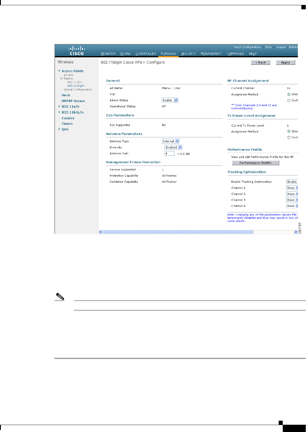
8-117
Cisco Wireless LAN Controller Configuration Guide
OL-21524-02
Chapter 8 Controlling Lightweight Access Points
Optimizing RFID Tracking on Access Points
Figure 8-53 802.11b/g/n Cisco APs > Configure Page
Step 9 Disable the access point radio by choosing Disable from the Admin Status drop-down list and click
Apply.
Step 10 Enable tracking optimization on the radio by choosing Enable from the Enable Tracking Optimization
drop-down list.
Step 11 From the four Channel drop-down lists, choose the channels on which you want to monitor RFID tags.
Note You must configure at least one channel on which the tags will be monitored.
Step 12 Click Apply to commit your changes.
Step 13 Click Save Configuration to save your changes.
Step 14 To reenable the access point radio, choose Enable from the Admin Status drop-down list and click Apply.
Step 15 Click Save Configuration to save your changes.

8-118
Cisco Wireless LAN Controller Configuration Guide
OL-21524-02
Chapter 8 Controlling Lightweight Access Points
Optimizing RFID Tracking on Access Points
Using the CLI to Optimize RFID Tracking on Access Points
To optimize RFID tracking using the controller CLI, follow these steps:
Step 1 Configure an access point for monitor mode by entering this command:
config ap mode monitor Cisco_AP
Step 2 When warned that the access point will be rebooted and asked if you want to continue, enter Y.
Step 3 Save your changes by entering this command:
save config
Step 4 Disable the access point radio by entering this command:
config 802.11b disable Cisco_AP
Step 5 Configure the access point to scan only the DCA channels supported by its country of operation by
entering this command:
config ap monitor-mode tracking-opt Cisco_AP
Note To specify the exact channels to be scanned, enter the config ap monitor-mode tracking-opt
Cisco_AP command in Step 6.
Note To disable tracking optimization for this access point, enter the config ap monitor-mode
no-optimization Cisco_AP command.
Step 6 After you have entered the command in Step 5, you can enter this command to choose up to four specific
802.11b channels to be scanned by the access point:
config ap monitor-mode 802.11b fast-channel Cisco_AP channel1 channel2 channel3 channel4
Note In the United States, you can assign any value between 1 and 11 (inclusive) to the channel
variable. Other countries support additional channels. You must assign at least one channel.
Step 7 Reenable the access point radio by entering this command:
config 802.11b enable Cisco_AP
Step 8 Save your changes by entering this command:
save config
Step 9 See a summary of all access points in monitor mode by entering this command:
show ap monitor-mode summary
Information similar to the following appears:
AP Name Ethernet MAC Status Scanning Channel List
------------------ -------------------- ---------- ------------------------
AP1131:46f2.98ac 00:16:46:f2:98:ac Tracking 1, 6, NA, NA

8-119
Cisco Wireless LAN Controller Configuration Guide
OL-21524-02
Chapter 8 Controlling Lightweight Access Points
Using the CLI to Configure Probe Request Forwarding
Using the CLI to Configure Probe Request Forwarding
Probe requests are 802.11 management frames sent by clients to request information about the
capabilities of SSIDs. By default, access points forward acknowledged probe requests to the controller
for processing. Acknowledged probe requests are probe requests for SSIDs that are supported by the
access point. If desired, you can configure access points to forward both acknowledged and
unacknowledged probe requests to the controller. The controller can use the information from
unacknowledged probe requests to improve the location accuracy.
To configure probe request filtering and rate limiting using the controller CLI, follow these steps:
Step 1 Enable or disable the filtering of probe requests forwarded from an access point to the controller by
entering this command:
config advanced probe filter {enable | disable}
If you enable probe filtering, the default filter setting, the access point forwards only acknowledged
probe requests to the controller. If you disable probe filtering, the access point forwards both
acknowledged and unacknowledged probe requests to the controller.
Step 2 Limit the number of probe requests sent to the controller per client per access point radio in a given
interval by entering this command:
config advanced probe limit num_probes interval
where
• num_probes is the number of probe requests (from 1 to 100) forwarded to the controller per client
per access point radio in a given interval.
• interval is the probe limit interval (from 100 to 10000 milliseconds).
The default value for num_probes is 2 probe requests, and the default value for interval is 500
milliseconds.
Step 3 Save your changes by entering this command:
save config
Step 4 See the probe request forwarding configuration by entering this command:
show advanced probe
Information similar to the following appears:
Probe request filtering.......................... Enabled
Probes fwd to controller per client per radio.... 2
Probe request rate-limiting interval.......... 500 msec
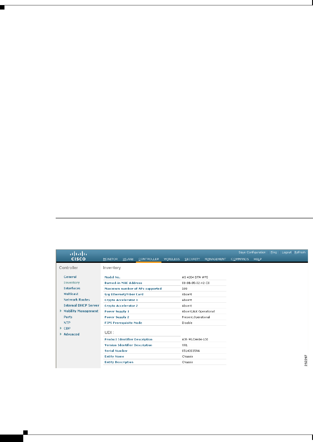
8-120
Cisco Wireless LAN Controller Configuration Guide
OL-21524-02
Chapter 8 Controlling Lightweight Access Points
Retrieving the Unique Device Identifier on Controllers and Access Points
Retrieving the Unique Device Identifier on Controllers and
Access Points
The unique device identifier (UDI) standard uniquely identifies products across all Cisco hardware
product families, enabling customers to identify and track Cisco products throughout their business and
network operations and to automate their asset management systems. The standard is consistent across
all electronic, physical, and standard business communications. The UDI consists of five data elements:
• The orderable product identifier (PID)
• The version of the product identifier (VID)
• The serial number (SN)
• The entity name
• The product description
The UDI is burned into the EEPROM of controllers and lightweight access points at the factory. It can
be retrieved through either the GUI or the CLI.
Using the GUI to Retrieve the Unique Device Identifier on Controllers and
Access Points
To retrieve the UDI on controllers and access points using the controller GUI, follow these steps:
Step 1 Choose Controller > Inventory to open the Inventory page (see Figure 8-54).
Figure 8-54 Inventory Page
This page shows the five data elements of the controller UDI.
Step 2 Choose Wireless > Access Points > All APs to open the All APs page.
Step 3 Click the name of the desired access point.
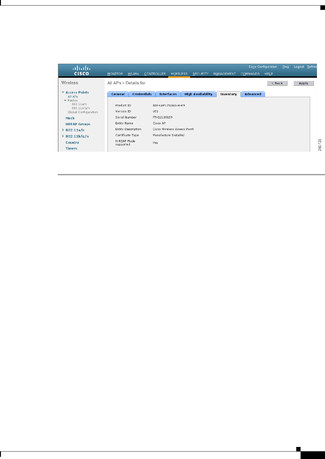
8-121
Cisco Wireless LAN Controller Configuration Guide
OL-21524-02
Chapter 8 Controlling Lightweight Access Points
Performing a Link Test
Step 4 Choose the Inventory tab to open the All APs > Details for (Inventory) page (see Figure 8-55).
Figure 8-55 All APs > Details for (Inventory) Page
This page shows the inventory information for the access point.
Using the CLI to Retrieve the Unique Device Identifier on Controllers and
Access Points
Use these commands to retrieve the UDI on controllers and access points using the controller CLI:
• show inventory—Shows the UDI string of the controller. Information similar to the following
appears:
NAME: "Chassis" , DESCR: "Cisco Wireless Controller"
PID: WS-C3750G-24PS-W24, VID: V01, SN: FLS0952H00F
• show inventory ap ap_id—Shows the UDI string of the access point specified.
Performing a Link Test
A link test is used to determine the quality of the radio link between two devices. Two types of link-test
packets are transmitted during a link test: request and response. Any radio receiving a link-test request
packet fills in the appropriate text boxes and echoes the packet back to the sender with the response type
set.
The radio link quality in the client-to-access point direction can differ from that in the access
point-to-client direction due to the asymmetrical distribution of the transmit power and receive
sensitivity on both sides. Two types of link tests can be performed: a ping test and a CCX link test.
With the ping link test, the controller can test link quality only in the client-to-access point direction.
The RF parameters of the ping reply packets received by the access point are polled by the controller to
determine the client-to-access point link quality.
With the CCX link test, the controller can also test the link quality in the access point-to-client direction.
The controller issues link-test requests to the client, and the client records the RF parameters (received
signal strength indicator [RSSI], signal-to-noise ratio [SNR], and so on). of the received request packet

8-122
Cisco Wireless LAN Controller Configuration Guide
OL-21524-02
Chapter 8 Controlling Lightweight Access Points
Performing a Link Test
in the response packet. Both the link-test requestor and responder roles are implemented on the access
point and controller. Not only can the access point or controller initiate a link test to a CCX v4 or v5
client, but a CCX v4 or v5 client can initiate a link test to the access point or controller.
The controller shows these link-quality metrics for CCX link tests in both directions (out— access point
to client; in— client to access point):
• Signal strength in the form of RSSI (minimum, maximum, and average)
• Signal quality in the form of SNR (minimum, maximum, and average)
• Total number of packets that are retried
• Maximum retry count for a single packet
• Number of lost packets
• Data rate of a successfully transmitted packet
The controller shows this metric regardless of direction:
• Link test request/reply round-trip time (minimum, maximum, and average)
The controller software supports CCX versions 1 through 5. CCX support is enabled automatically for
every WLAN on the controller and cannot be disabled. The controller stores the CCX version of the
client in its client database and uses it to limit the features for this client. If a client does not support
CCXv4 or v5, the controller performs a ping link test on the client. If a client supports CCXv4 or v5, the
controller performs a CCX link test on the client. If a client times out during a CCX link test, the
controller switches to the ping link test automatically. See the “Configuring Cisco Client Extensions”
section on page 7-52 for more information on CCX.
Note CCX is not supported on the AP1030.
Follow the instructions in this section to perform a link test using either the GUI or the CLI.
Using the GUI to Perform a Link Test
To run a link test using the controller GUI, follow these steps:
Step 1 Choose Monitor > Clients to open the Clients page (see Figure 8-56).
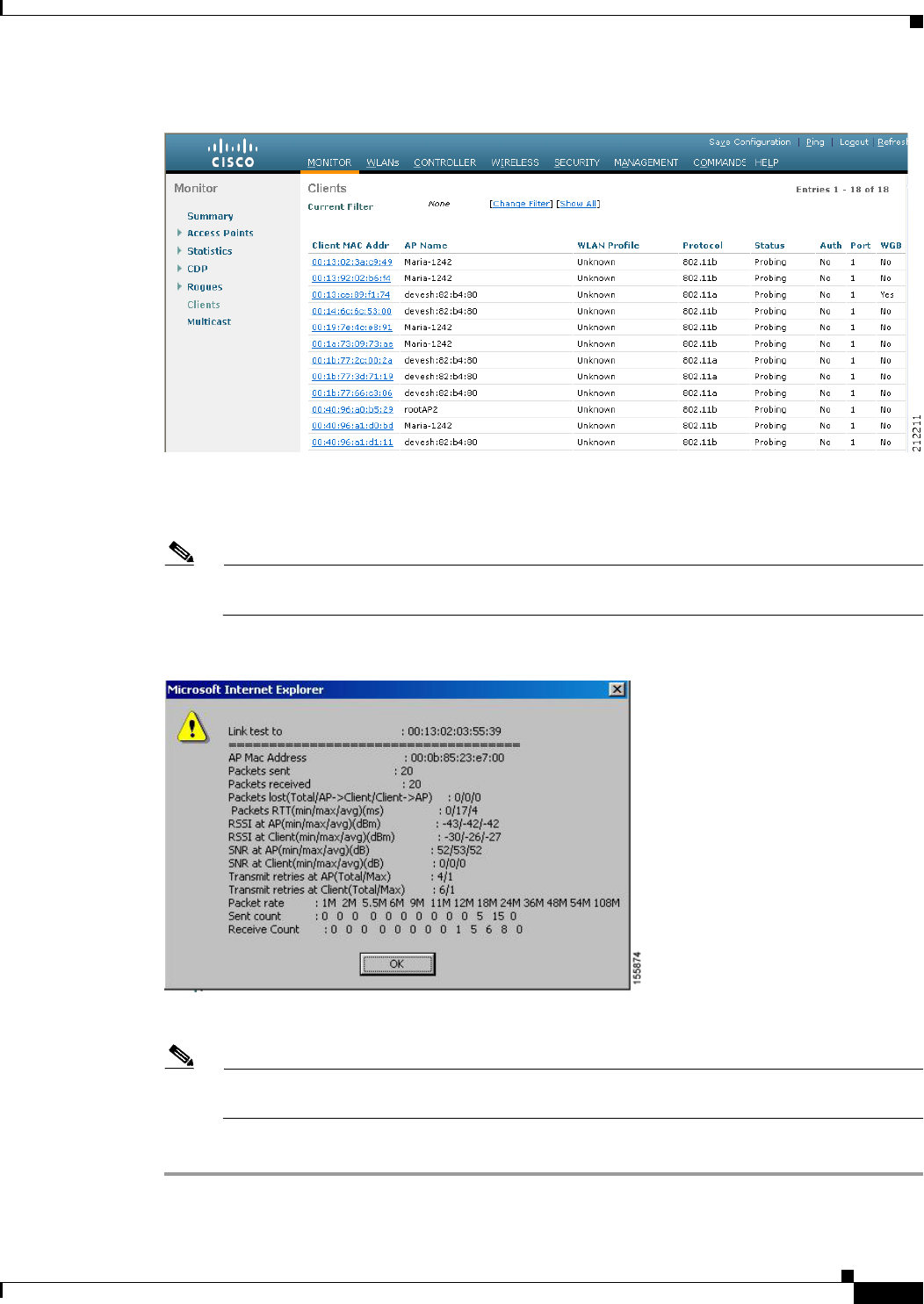
8-123
Cisco Wireless LAN Controller Configuration Guide
OL-21524-02
Chapter 8 Controlling Lightweight Access Points
Performing a Link Test
Figure 8-56 Clients Page
Step 2 Hover your cursor over the blue drop-down arrow for the desired client and choose LinkTest. A link test
page appears (see Figure 8-57).
Note You can also access this page by clicking the MAC address of the desired client and then clicking
the Link Test button on the top of the Clients > Detail page.
Figure 8-57 Link Test Page
This page shows the results of the CCX link test.
Note If the client and/or controller does not support CCX v4 or later releases, the controller performs
a ping link test on the client instead, and a much more limited link test page appears.
Step 3 Click OK to exit the link test page.

8-124
Cisco Wireless LAN Controller Configuration Guide
OL-21524-02
Chapter 8 Controlling Lightweight Access Points
Configuring Link Latency
Using the CLI to Perform a Link Test
Use these commands to run a link test using the controller CLI:
• Run a link test by entering this command:
linktest ap_mac
When CCX v4 or later releases is enabled on both the controller and the client being tested,
information similar to the following appears:
CCX Link Test to 00:0d:88:c5:8a:d1.
Link Test Packets Sent...................................... 20
Link Test Packets Received................................. 10
Link Test Packets Lost (Total/AP to Client/Client to AP).... 10/5/5
Link Test Packets round trip time (min/max/average)......... 5ms/20ms/15ms
RSSI at AP (min/max/average)................................ -60dBm/-50dBm/-55dBm
RSSI at Client (min/max/average)............................ -50dBm/-40dBm/-45dBm
SNR at AP (min/max/average)................................. 40dB/30dB/35dB
SNR at Client (min/max/average)............................. 40dB/30dB/35dB
Transmit Retries at AP (Total/Maximum)...................... 5/3
Transmit Retries at Client (Total/Maximum).................. 4/2
Transmit rate: 1M 2M 5.5M 6M 9M 11M 12M 18M 24M 36M 48M 54M 108M
Packet Count: 0 0 0 0 0 0 0 0 0 2 0 18 0
Transmit rate: 1M 2M 5.5M 6M 9M 11M 12M 18M 24M 36M 48M 54M 108M
Packet Count: 0 0 0 0 0 0 0 0 0 2 0 8 0
When CCX v4 or later releases is not enabled on either the controller or the client being tested, fewer
details appear:
Ping Link Test to 00:0d:88:c5:8a:d1.
Link Test Packets Sent.......................... 20
Link Test Packets Received...................... 20
Local Signal Strength........................... -49dBm
Local Signal to Noise Ratio..................... 39dB
• Adjust the link-test parameters that are applicable to both the CCX link test and the ping test by
entering these commands from configuration mode:
linktest frame-size size_of_link-test_frames
linktest num-of-frame number_of_link-test_request_frames_per_test
Configuring Link Latency
You can configure link latency on the controller to measure the link between an access point and the
controller. This feature can be used with all access points joined to the controller but is especially useful
for hybrid-REAP and OfficeExtend access points, for which the link could be a slow or unreliable WAN
connection.
Note Link latency is supported for use only with hybrid-REAP access points in connected mode.
Hybrid-REAP access points in standalone mode are not supported.
Link latency monitors the round-trip time of the CAPWAP heartbeat packets (echo request and response)
from the access point to the controller and back. This time can vary due to the network link speed and
controller processing loads. The access point timestamps the outgoing echo requests to the controller
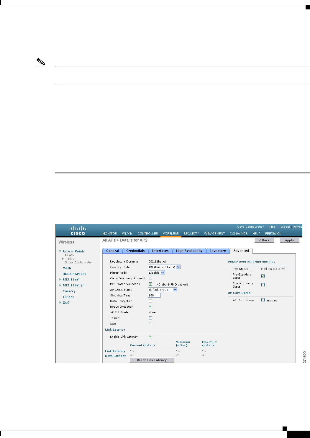
8-125
Cisco Wireless LAN Controller Configuration Guide
OL-21524-02
Chapter 8 Controlling Lightweight Access Points
Configuring Link Latency
and the echo responses received from the controller. The access point sends this delta time to the
controller as the system round-trip time. The access point sends heartbeat packets to the controller at a
default interval of 30 seconds.
Note Link latency calculates the CAPWAP response time between the access point and the controller. It does
not measure network latency or ping responses.
The controller displays the current round-trip time as well as a running minimum and maximum
round-trip time. The minimum and maximum times continue to run as long as the controller is up or can
be cleared and allowed to restart.
You can configure link latency for a specific access point using the controller GUI or CLI or for all
access points joined to the controller using the CLI.
Using the GUI to Configure Link Latency
To configure link latency using the controller GUI, follow these steps:
Step 1 Choose Wireless > Access Points > All APs to open the All APs page.
Step 2 Click the name of the access point for which you want to configure link latency.
Step 3 Choose the Advanced tab to open the All APs > Details for (Advanced) page (see Figure 8-58).
Figure 8-58 All APs > Details for (Advanced) Page
Step 4 Select the Enable Link Latency check box to enable link latency for this access point or unselect it to
prevent the access point from sending the round-trip time to the controller after every echo response is
received. The default value is unselected.
Step 5 Click Apply to commit your changes.

8-126
Cisco Wireless LAN Controller Configuration Guide
OL-21524-02
Chapter 8 Controlling Lightweight Access Points
Configuring Link Latency
Step 6 Click Save Configuration to save your changes.
Step 7 When the All APs page reappears, click the name of the access point again.
Step 8 When the All APs > Details for page reappears, choose the Advanced tab again. The link latency and
data latency results appear below the Enable Link Latency check box:
• Current—The current round-trip time (in milliseconds) of CAPWAP heartbeat packets or data
packets from the access point to the controller and back.
• Minimum—Since link latency has been enabled or reset, the minimum round-trip time (in
milliseconds) of CAPWAP heartbeat packets or data packets from the access point to the controller
and back.
• Maximum—Since link latency has been enabled or reset, the maximum round-trip time (in
milliseconds) of CAPWAP heartbeat packets or data packets from the access point to the controller
and back.
Step 9 To clear the current, minimum, and maximum link latency and data latency statistics on the controller
for this access point, click Reset Link Latency.
Step 10 After the page refreshes and the All APs > Details for page reap]pears, choose the Advanced tab. The
updated statistics appear in the Minimum and Maximum text boxes.
Using the CLI to Configure Link Latency
To configure link latency using the controller CLI, follow these steps:
Step 1 Enable or disable link latency for a specific access point or for all access points currently associated to
the controller by entering this command:
config ap link-latency {enable | disable} {Cisco_AP | all}
The default value is disabled.
Note The config ap link-latency {enable | disable} all command enables or disables link latency
only for access points that are currently joined to the controller. It does not apply to access points
that join in the future.
Step 2 See the link latency results for a specific access point by entering this command:
show ap config general Cisco_AP
Information similar to the following appears:
Cisco AP Identifier.............................. 1
Cisco AP Name.................................... AP1
...
AP Link Latency.................................. Enabled
Current Delay................................... 1 ms
Maximum Delay................................... 1 ms
Minimum Delay................................... 1 ms
Last updated (based on AP Up Time)........... 0 days, 05 h 03 m 25 s
The output of this command contains the following link latency results:
• Current Delay—The current round-trip time (in milliseconds) of CAPWAP heartbeat packets from
the access point to the controller and back.

8-127
Cisco Wireless LAN Controller Configuration Guide
OL-21524-02
Chapter 8 Controlling Lightweight Access Points
Configuring the TCP MSS
• Maximum Delay—Since link latency has been enabled or reset, the maximum round-trip time (in
milliseconds) of CAPWAP heartbeat packets from the access point to the controller and back.
• Minimum Delay—Since link latency has been enabled or reset, the minimum round-trip time (in
milliseconds) of CAPWAP heartbeat packets from the access point to the controller and back.
Step 3 Clear the current, minimum, and maximum link latency statistics on the controller for a specific access
point by entering this command:
config ap link-latency reset Cisco_AP
Step 4 See the results of the reset by entering this command:
show ap config general Cisco_AP
Configuring the TCP MSS
If the client’s maximum segment size (MSS) in a Transmission Control Protocol (TCP) three-way
handshake is greater than the maximum transmission unit can handle, the client might experience
reduced throughput and the fragmentation of packets. To avoid this problem in controller software
release 6.0 or later releases, you can specify the MSS for all access points that are joined to the controller
or for a specific access point.
When you enable this feature, the access point selects for TCP packets to and from wireless clients in its
data path. If the MSS of these packets is greater than the value that you configured or greater than the
default value for the CAPWAP tunnel, the access point changes the MSS to the new configured value.
Using the CLI to Configure TCP MSS
To configure the TCP MSS using the controller CLI, follow these steps:
Step 1 Enable or disable the TCP MSS on a particular access point or on all access points by entering this
command:
config ap tcp-adjust-mss {enable | disable} {Cisco_AP | all} size
where the size parameter is a value between 536 and 1363 bytes. The default value varies for different
clients.
Step 2 Save your changes by entering this command:
save config
Step 3 Reboot the controller in order for your change to take effect by entering this command:
reset system
Step 4 See the current TCP MSS setting for a particular access point or all access points by entering this
command:
show ap tcp-mss-adjust {Cisco_AP | all}
Information similar to the following appears:
AP Name TCP State MSS Size
------------------ -------- -------
AP-1140 enabled 536
AP-1240 disabled -

8-128
Cisco Wireless LAN Controller Configuration Guide
OL-21524-02
Chapter 8 Controlling Lightweight Access Points
Configuring Power over Ethernet
AP-1130 disabled -
Configuring Power over Ethernet
When an access point that has been converted to lightweight mode (such as an AP1131 or AP1242) or a
1250 series access point is powered by a power injector that is connected to a Cisco pre-Intelligent Power
Management (pre-IPM) switch, you need to configure Power over Ethernet (PoE), also known as inline
power.
The dual-radio 1250 series access points can operate in four different modes when powered using PoE:
• 20.0 W (Full Power)—This mode is equivalent to using a power injector or an AC/DC adapter.
• 16.8 W—Both transmitters are used but at reduced power. Legacy data rates are not affected, but the
M0 to M15 data rates are reduced in the 2.4-GHz band. Throughput should be minimally impacted
because all data rates are still enabled. The range is affected because of the lower transmit power.
All receivers remain enabled.
• 15.4 W—Only a single transmitter is enabled. Legacy data rates and M0 to M7 rates are minimally
affected. M8 to M15 rates are disabled because they require both transmitters. Throughput is better
than that received with legacy access points but less than the 20 and 16.8 W power modes.
• 11.0 W (Low Power)—The access point runs, but both radios are disabled.
Note When a dual-radio 1250 series access point is powered using 15.4-W PoE, it cannot operate at full
functionality, which requires 20 W. The access point can operate with dual radios on 15.4-W PoE, but
performance is reduced in terms of throughput and range. If full functionality is required on 15.4 W, you
can remove one of the radios from the 1250 series access point chassis or disable it in controller software
release 6.0 or later releases so that the other radio can operate in full 802.11n mode. After the access
point radio is administratively disabled, the access point must be rebooted for the change to take effect.
The access point must also be rebooted after you reenable the radio to put it into reduced throughput
mode.
These modes provide the flexibility of running the 1250 series access points with the available wired
infrastructure to obtain the desired level of performance. With enhanced PoE switches (such as the Cisco
Catalyst 3750-E Series Switches), the 1250 series access points can provide maximum features and
functionality with a minimum total cost of ownership. Alternatively, if you decide to power the access
point with the existing PoE (802.3af) switches, the access point chooses the appropriate mode of
operation based on whether it has one radio or two.
Note For more information on the Cisco PoE switches, see this URL:
http://www.cisco.com/en/US/prod/switches/epoe.html

8-129
Cisco Wireless LAN Controller Configuration Guide
OL-21524-02
Chapter 8 Controlling Lightweight Access Points
Configuring Power over Ethernet
Table 8-21 shows the maximum transmit power settings for 1250 series access points using PoE.
Note When powered with a non-Cisco standard PoE switch, the 1250 series access point operates under 15.4
Watts. Even if the non-Cisco switch or midspan device is capable of providing higher power, the access
point does not operate in enhanced PoE mode.
You can configure PoE through either the controller GUI or CLI.
Using the GUI to Configure Power over Ethernet
To configure PoE using the controller GUI, follow these steps:
Step 1 Choose Wireless > Access Points > All APs and then the name of the desired access point.
Step 2 Choose the Advanced tab to open the All APs > Details for (Advanced) page (see Figure 8-59).
Ta b l e 8-21 Maximum Transmit Power Settings for 1250 Series Access Points Using PoE
Radio
Band
Data Rates Number of
Transmitters
Cyclic Shift
Diversity (CSD)
Maximum Transmit Power (dBm)1
802.3af Mode
(15.4 W)
ePoE Power
Optimized
Mode (16.8 W)
ePoE Mode
(20 W)
2.4 GHz 802.11b 1 — 20 20 20
802.11g 1 — 17 17 17
802.11n MCS 0-7 1
2
Disabled
Enabled (default)
17
Disabled
17
14 (11 per Tx)
17
20 (17 per Tx)
802.11n MCS 8-15 2 — Disabled 14 (11 per Tx) 20 (17 per Tx)
5 GHz 802.11a 1—17 17 17
802.11n MCS 0-7 1
2
Disabled
Enabled (default)
17
Disabled
17
20 (17 per Tx)
17
20 (17 per Tx)
802.11n MCS 8-15 2 — Disabled 20 (17 per Tx) 20 (17 per Tx)
1. Maximum transmit power varies by channel and according to individual country regulations. See the product documentation
for specific details.
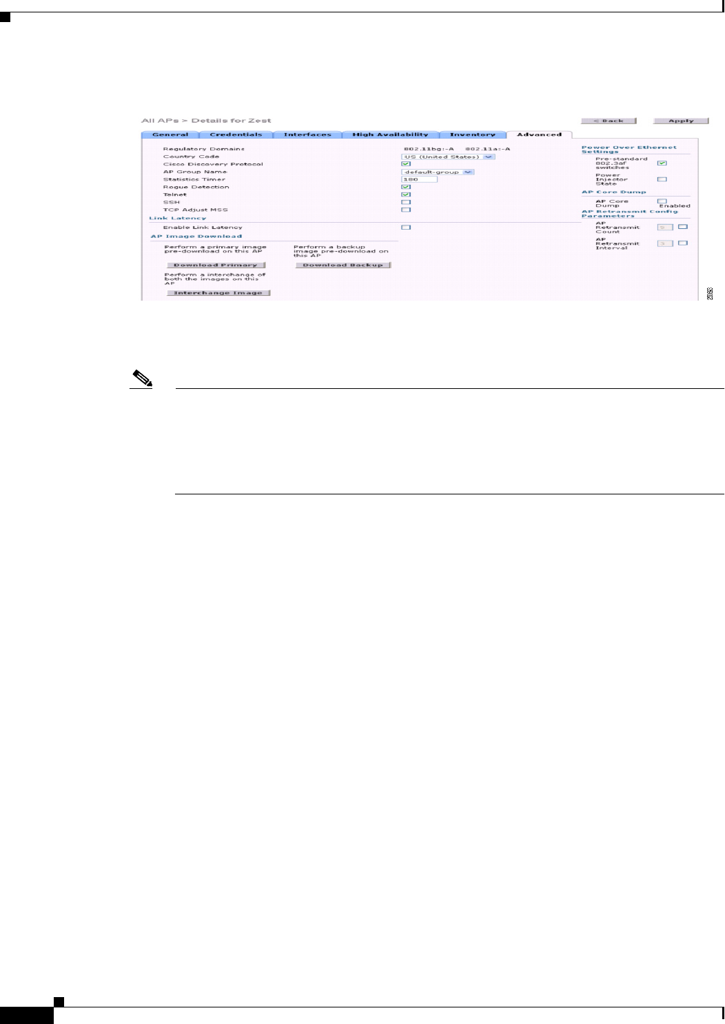
8-130
Cisco Wireless LAN Controller Configuration Guide
OL-21524-02
Chapter 8 Controlling Lightweight Access Points
Configuring Power over Ethernet
Figure 8-59 All APs > Details for (Advanced) Page
The PoE Status text box shows the power level at which the access point is operating: High (20 W),
Medium (16.8 W), or Medium (15.4 W). This text box is not configurable. The controller auto-detects
the access point’s power source and displays the power level here.
Note This text box applies only to 1250 series access points that are powered using PoE. There are
two other ways to determine if the access point is operating at a lower power level. First, the
“Due to low PoE, radio is transmitting at degraded power” message appears under the Tx Power
Level Assignment section on the 802.11a/n (or 802.11b/g/n) Cisco APs > Configure page.
Second, the “PoE Status: degraded operation” message appears in the controller’s trap log on the
Trap Logs page.
Step 3 Perform one of the following:
• Select the Pre-standard 802.3af switches check box if the access point is being powered by a
high-power 802.3af Cisco switch. Thise switch provides more than the traditional 6 Watts of power
but do not support the intelligent power management (IPM) feature.
• Unselect the Pre-standard 802.3af switches check box if power is being provided by a power
injector. This is the default value.
Step 4 Select the Power Injector State check box if the attached switch does not support IPM and a power
injector is being used. If the attached switch supports IPM, you do not need to select this check box.
Step 5 If you selected the Power Injector State check box in the previous step, the Power Injector Selection and
Injector Switch MAC Address parameters appear. The Power Injector Selection parameter enables you
to protect your switch port from an accidental overload if the power injector is inadvertently bypassed.
Choose one of these options from the drop-down list to specify the desired level of protection:
• Installed—This option examines and remembers the MAC address of the currently connected
switch port and assumes that a power injector is connected. Choose this option if your network
contains older Cisco 6-Watt switches and you want to avoid possible overloads by forcing a
double-check of any relocated access points.
If you want to configure the switch MAC address, enter the MAC address in the Injector Switch
MAC Address text box. If you want the access point to find the switch MAC address, leave the
Injector Switch MAC Address text box blank.

8-131
Cisco Wireless LAN Controller Configuration Guide
OL-21524-02
Chapter 8 Controlling Lightweight Access Points
Configuring Power over Ethernet
Note Each time an access point is relocated, the MAC address of the new switch port fails to
match the remembered MAC address, and the access point remains in low-power mode. You
must then physically verify the existence of a power injector and reselect this option to cause
the new MAC address to be remembered.
• Override—This option allows the access point to operate in high-power mode without first
verifying a matching MAC address. You can use this option if your network does not contain any
older Cisco 6-W switches that could be overloaded if connected directly to a 12-W access point. The
advantage of this option is that if you relocate the access point, it continues to operate in high-power
mode without any further configuration. The disadvantage of this option is that if the access point
is connected directly to a 6-W switch, an overload occurs.
Step 6 Click Apply to commit your changes.
Step 7 If you have a dual-radio 1250 series access point and want to disable one of its radios in order to enable
the other radio to receive full power, follow these steps:
a. Choose Wireless > Access Points > Radios > 802.11a/n or 802.11b/g/n to open the 802.11a/n (or
802.11b/g/n) Radios page.
b. Hover your cursor over the blue drop-down arrow for the radio that you want to disable and choose
Configure.
c. On the 802.11a/n (or 802.11b/g/n) Cisco APs > Configure page, choose Disable from the Admin
Status drop-down list.
d. Click Apply to commit your changes.
e. Manually reset the access point in order for the change to take effect.
Step 8 Click Save Configuration to save your settings.
Using the CLI to Configure Power over Ethernet
Use these commands to configure and See PoE settings using the controller CLI:
• If your network contains any older Cisco 6-W switches that could be accidentally overloaded if
connected directly to a 12-W access point, enter this command:
config ap power injector enable {Cisco_AP | all} installed
The access point remembers that a power injector is connected to this particular switch port. If you
relocate the access point, you must reissue this command after the presence of a new power injector
is verified.
Note Make sure CDP is enabled before entering this command. Otherwise, this command will fail.
See the “Configuring the Cisco Discovery Protocol” section on page 4-96 for information
on enabling CDP.
• Remove the safety checks and allow the access point to be connected to any switch port by entering
this command:
config ap power injector enable {Cisco_AP | all} override

8-132
Cisco Wireless LAN Controller Configuration Guide
OL-21524-02
Chapter 8 Controlling Lightweight Access Points
Configuring Flashing LEDs
You can use this command if your network does not contain any older Cisco 6-W switches that could
be overloaded if connected directly to a 12-W access point. The access point assumes that a power
injector is always connected. If you relocate the access point, it continues to assume that a power
injector is present.
• If you know the MAC address of the connected switch port and do not want to automatically detect
it using the installed option, enter this command:
config ap power injector enable {Cisco_AP | all} switch_port_mac_address
• If you have a dual-radio 1250 series access point and want to disable one of its radios in order to
enable the other radio to receive full power, enter this command:
config {802.11a | 802.11b} disable Cisco_AP
Note You must manually reset the access point in order for the change to take effect.
• See the PoE settings for a specific access point by entering this command:
show ap config general Cisco_AP
Information similar to the following appears:
Cisco AP Identifier.............................. 1
Cisco AP Name.................................... AP1
...
PoE Pre-Standard Switch.......................... Enabled
PoE Power Injector MAC Addr...................... Disabled
Power Type/Mode.................................. PoE/Low Power (degraded mode)
...
The Power Type/Mode text box shows “degraded mode” if the access point is not operating at full
power.
• See the controller’s trap log by entering this command:
show traplog
If the access point is not operating at full power, the trap contains “PoE Status: degraded operation.”
Configuring Flashing LEDs
Controller software release 4.0 or later releases enables you to flash the LEDs on an access point in order
to locate it. All IOS lightweight access points support this feature.
Use these commands to configure LED flashing from the privileged EXEC mode of the controller:
Note The output of these commands is sent only to the controller console, regardless of whether the commands
were entered on the console or in a TELNET/SSH CLI session.
• Enable the controller to send commands to the access point from its CLI by entering this command:
debug ap enable Cisco_AP
• Cause a specific access point to flash its LEDs for a specified number of seconds by entering this
command:
debug ap command “led flash seconds” Cisco_AP
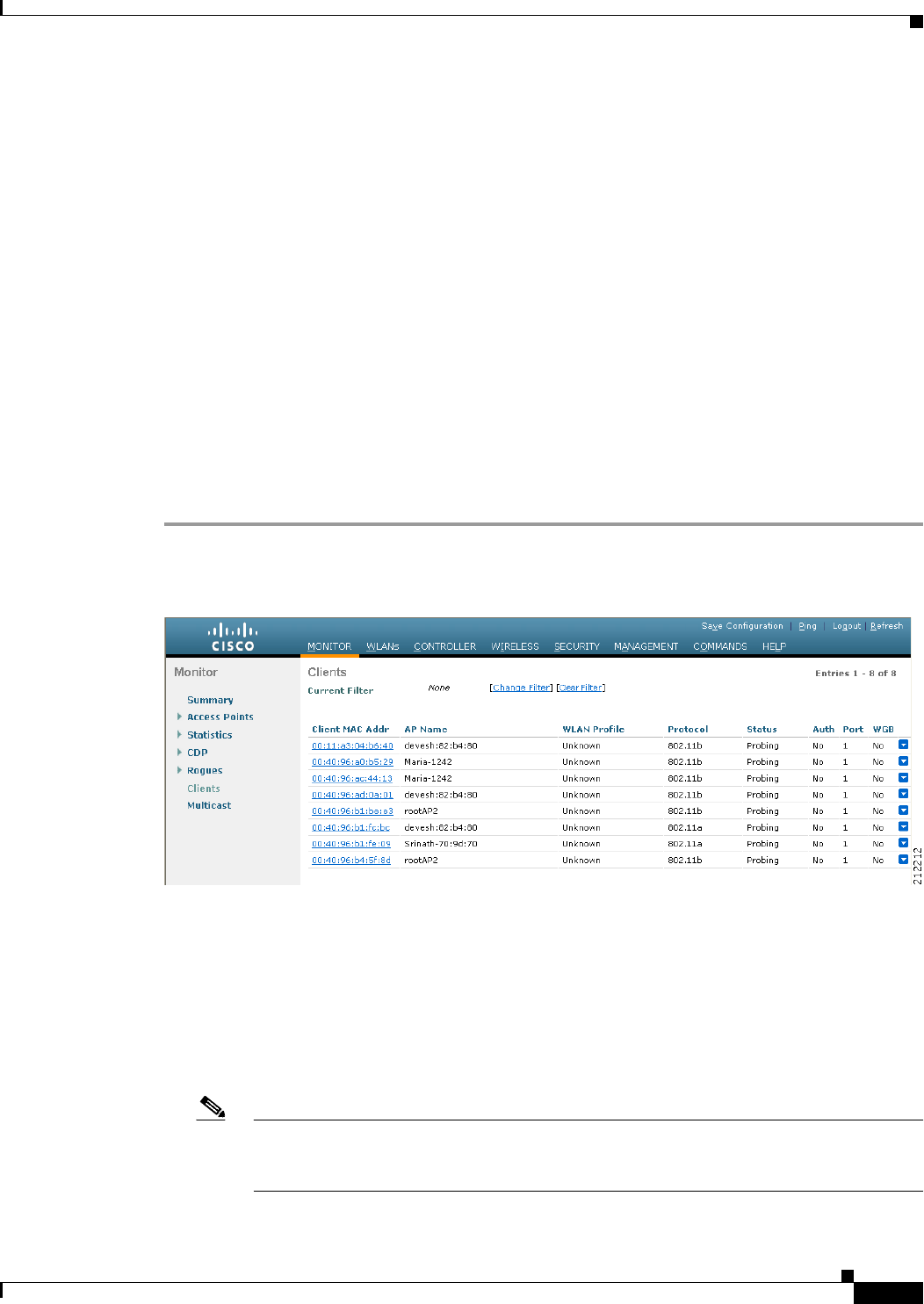
8-133
Cisco Wireless LAN Controller Configuration Guide
OL-21524-02
Chapter 8 Controlling Lightweight Access Points
Viewing Clients
You can enter a value between 1 and 3600 seconds for the seconds parameter.
• Disable LED flashing for a specific access point by entering this command:
debug ap command “led flash disable” Cisco_AP
This command disables LED flashing immediately. For example, if you run the previous command
(with the seconds parameter set to 60 seconds) and then disable LED flashing after only 20 seconds,
the access point’s LEDs stop flashing immediately.
Viewing Clients
You can use the controller GUI or CLI to view information about the clients that are associated to the
controller’s access points.
Using the GUI to View Clients
To view client information using the controller GUI, follow these steps:
Step 1 Choose Monitor > Clients to open the Clients page (see Figure 8-60).
Figure 8-60 Clients Page
This page lists all of the clients that are associated to the controller’s access points. It provides the
following information for each client:
• The MAC address of the client
• The name of the access point to which the client is associated
• The name of the WLAN used by the client
• The type of client (802.11a, 802.11b, 802.11g, or 802.11n)
Note If the 802.11n client associates to an 802.11a radio that has 802.11n enabled, then the client
type shows as 802.11n(5). If the 802.11n client associates to an 802.11b/g radio with
802.11n enabled, then the client type shows as 802.11n (2.4).
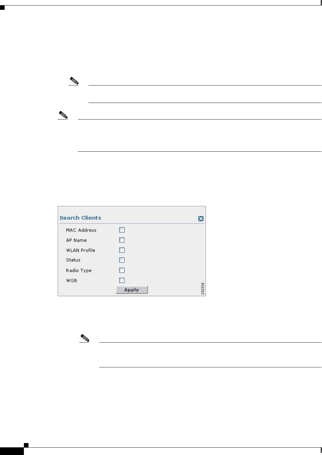
8-134
Cisco Wireless LAN Controller Configuration Guide
OL-21524-02
Chapter 8 Controlling Lightweight Access Points
Viewing Clients
• The status of the client connection
• The authorization status of the client
• The port number of the access point to which the client is associated
• An indication of whether the client is a WGB
Note See the “Cisco Workgroup Bridges” section on page 8-88 for more information on the WGB
status.
Note If you want to remove or disable a client, hover your cursor over the blue drop-down arrow for
that client and choose Remove or Disable, respectively. If you want to test the connection
between the client and the access point, hover your cursor over the blue drop-down arrow for
that client and choose Link Test.
Step 2 Create a filter to display only clients that meet certain criteria (such as the MAC address, status, or radio
type) as follows:
a. Click Change Filter to open the Search Clients dialog box (see Figure 8-61).
Figure 8-61 Search Clients Dialog Box
b. Select one or more of the following check boxes to specify the criteria used when displaying clients:
• MAC Address—Enter a client MAC address.
Note When you enable the MAC address filter, the other filters are disabled automatically.
When you enable any of the other filters, the MAC address filter is disabled
automatically.
• AP Name—Enter the name of an access point.
• WLAN Profile—Choose one of the available WLAN profiles from the drop-down list.
• Status—Select the Associated, Authenticated, Excluded, and/or Idle check boxes.
• Radio Type—Choose 802.11a, 802.11b, 802.11g, 802.11an, 802.11bn or Mobile.
• WGB—Enter the WGB clients associated to the controller’s access points.

8-135
Cisco Wireless LAN Controller Configuration Guide
OL-21524-02
Chapter 8 Controlling Lightweight Access Points
Viewing Clients
c. Click Apply to commit your changes. The Current Filter parameter at the top of the Clients page
shows the filters that are currently applied.
Note If you want to remove the filters and display the entire client list, click Clear Filter.
Step 3 Click the MAC address of the client to view detailed information for a specific client. The
Clients > Detail page appears (see Figure 8-62).
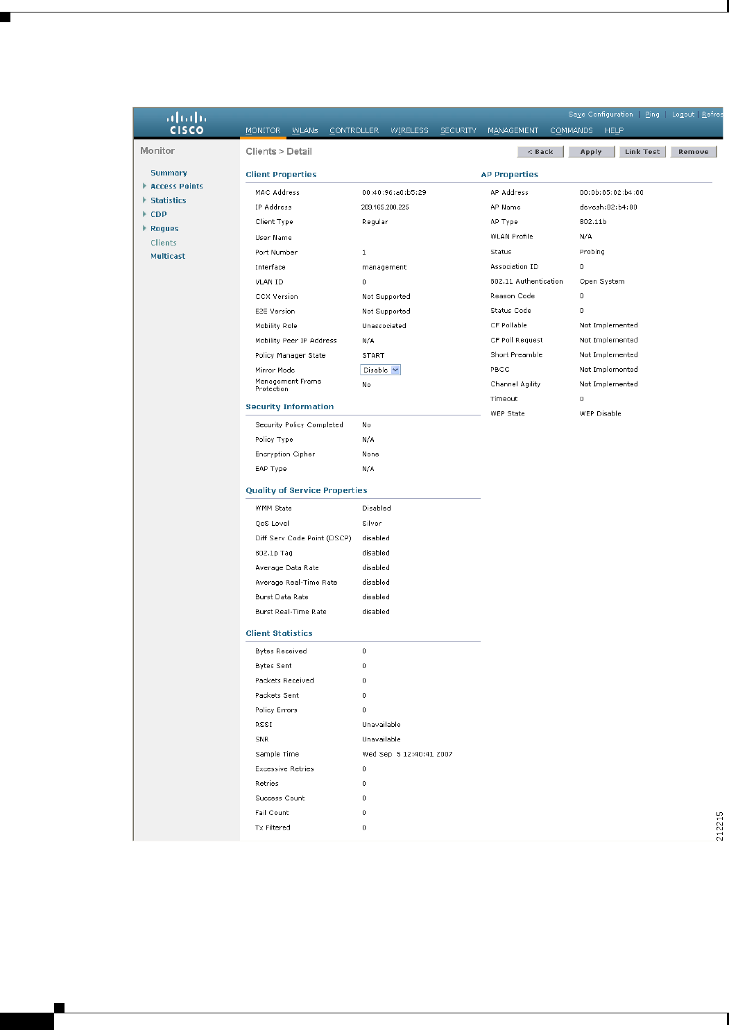
8-136
Cisco Wireless LAN Controller Configuration Guide
OL-21524-02
Chapter 8 Controlling Lightweight Access Points
Viewing Clients
Figure 8-62 Clients > Detail Page
This page shows the following information:
• The general properties of the client
• The security settings of the client
• The QoS properties of the client

8-137
Cisco Wireless LAN Controller Configuration Guide
OL-21524-02
Chapter 8 Controlling Lightweight Access Points
Viewing Clients
• Client statistics
• The properties of the access point to which the client is associated
Using the CLI to View Clients
Use these commands to view client information:
• See the clients associated to a specific access point by entering this command:
show client ap {802.11a | 802.11b} Cisco_AP
Information similar to the following appears:
MAC Address AP Id Status WLAN Id Authenticated
----------------- ------ ------------- --------- -------------
00:13:ce:cc:8e:b8 1 Associated 1 No
• See a summary of the clients associated to the controller’s access points by entering this command:
show client summary
Information similar to the following appears:
Number of Clients................................ 1
MAC Address AP Name Status WLAN/Guest-Lan Auth Protocol Port Wired
----------------- ------------- ---------- --------------- ---- -------- ---- -----
00:13:02:2d:96:24 AP_1130 Associated 1 Yes 802.11a 1 No
• See detailed information for a specific client by entering this command:
show client detail client_mac
Information similar to the following appears:
Client MAC Address............................... 00:40:96:b2:a3:44
Client Username ................................. N/A
AP MAC Address................................... 00:18:74:c7:c0:90
Client State..................................... Associated
Wireless LAN Id.................................. 1
BSSID............................................ 00:18:74:c7:c0:9f
Channel.......................................... 56
IP Address....................................... 192.168.10.28
Association Id................................... 1
Authentication Algorithm......................... Open System
Reason Code...................................... 0
Status Code...................................... 0
Session Timeout.................................. 0
Client CCX version............................... 5
Client E2E version............................... No E2E support
Diagnostics Capability........................... Supported
S69 Capability................................... Supported
Mirroring........................................ Disabled
QoS Level........................................ Silver
...

8-138
Cisco Wireless LAN Controller Configuration Guide
OL-21524-02
Chapter 8 Controlling Lightweight Access Points
Viewing Clients

CHAPTER
9-1
Cisco Wireless LAN Controller Configuration Guide
OL-21524-02
9
Controlling Mesh Access Points
This chapter describes Cisco indoor and outdoor mesh access points and explains how to connect them
to the controller and manage access point settings. It contains these sections:
• Cisco Aironet Mesh Access Points, page 9-1
• Architecture Overview, page 9-12
• Adding Mesh Access Points to the Mesh Network, page 9-23
• Configuring Advanced Features, page 9-72
• Slot Bias Options, page 9-112
• Viewing Mesh Statistics for a Mesh Access Point, page 9-116
• Viewing Neighbor Statistics for a Mesh Access Point, page 9-121
• Converting Indoor Access Points to Mesh Access Points, page 9-124
• Changing MAP and RAP Roles for Indoor Mesh Access Points, page 9-125
• Converting Indoor Mesh Access Points to Nonmesh Lightweight Access Points (1130AG, 1240AG),
page 9-126
• Configuring Mesh Access Points to Operate with Cisco 3200 Series Mobile Access Routers,
page 9-127
Cisco Aironet Mesh Access Points
Mesh networking employs Cisco Aironet 1500 Series outdoor mesh access points and indoor mesh
access points (Cisco Aironet 1040, 1130, 1140, 1240, 1250, 1260, 3500e, and 3500i series access points)
along with the Cisco Wireless LAN Controller, and Cisco Wireless Control System (WCS) to provide
scalable, central management, and mobility between indoor and outdoor deployments. Control and
Provisioning of Wireless Access Points (CAPWAP) protocol manages the connection of mesh access
points to the network.
End-to-end security within the mesh network is supported by employing Advanced Encryption Standard
(AES) encryption between the wireless mesh access points and Wi-Fi Protected Access 2 (WPA2)
clients. This document also outlines radio frequency (RF) components to consider when designing an
outdoor network.
Controller software release 7.0.116.0 and later releases supports these Cisco Aironet mesh access points:
• Cisco Aironet 1520 series outdoor mesh access points consist of the 1522 dual-radio mesh access
point and the 1524PS/Serial Backhaul multi-radio mesh access point.

9-2
Cisco Wireless LAN Controller Configuration Guide
OL-21524-02
Chapter 9 Controlling Mesh Access Points
Cisco Aironet Mesh Access Points
Note See the Cisco Aironet 1520 Series Outdoor Mesh Access Point Hardware Installation Guide
for details on the physical installation and initial configuration of the mesh access points at
the following URL:
http://www.cisco.com/en/US/products/ps8368/tsd_products_support_series_home.html
Note AP1130 and AP1240 must be converted to operate as indoor mesh access points. See the
“Converting Indoor Access Points to Mesh Access Points” section on page 9-124.
• Cisco Aironet 1550 series outdoor mesh access points consist of four models:
–
1552E
–
1552C
–
1552I
–
1552H
Note See the Cisco Mesh Access Points, Design and Deployment Guidefor details:
http://www.cisco.com/en/US/docs/wireless/technology/mesh/7.0MR1/design/guide/MeshA
P_70MR1.html
In the 7.0.98.0 release, indoor mesh is available on Cisco Aironet 1130 and 1240 series access
points. In the 7.0.116.0 release, indoor mesh is also available on 11n access points (Cisco Aironet
1040, 1140, 1250, 1260, 3500e, and 3500i series access points).
Note All features discussed in this chapter apply to indoor (1040, 1140, 1250, 1260, 3500) and outdoor mesh
access points (1500 series) unless noted otherwise. Mesh access point or MAP is hereafter used to refer
to both indoor and outdoor mesh access points.
Note Cisco Aironet 1505 and 1510 access points are not supported in this release.
Note See the Release Notes for Cisco Wireless LAN controllers and Lightweight Access Points for Release
7.0.116.0 for mesh feature summary, important notes, and software upgrade steps for migrating from
4.1.19x.xx mesh releases to controller release7.0.116.0 at this URL:
http://www.cisco.com/en/US/products/ps6366/prod_release_notes_list.html.
Access Point Roles
Access points within a mesh network operate as either a Root Access Point (RAP) or a Mesh Access
Point (MAP).
RAPs have wired connections to their controller, and MAPs have wireless connections to their controller.

9-3
Cisco Wireless LAN Controller Configuration Guide
OL-21524-02
Chapter 9 Controlling Mesh Access Points
Cisco Aironet Mesh Access Points
MAPs communicate among themselves and back to the RAP using wireless connections over the
802.11a radio backhaul. MAPs use the Cisco Adaptive Wireless Path Protocol (AWPP) to determine the
best path through the other mesh access points to the controller.
All the possible paths between the MAPs and RAPs form the wireless mesh network. Figure 9-1 shows
the relationship between RAPs and MAPs in a mesh network.
Figure 9-1 Simple Mesh Network Hierarchy
Network Access
Wireless mesh networks can simultaneously carry two different traffic types: wireless LAN client traffic
and MAP Ethernet port traffic.
Wireless LAN client traffic terminates on the controller, and the Ethernet traffic terminates on the
Ethernet ports of the mesh access points.
Access to the wireless LAN mesh for mesh access points is managed by:
• MAC authentication—Mesh access points are added to a database to ensure that they are allowed
access to a given controller and the mesh network. See the “Converting Indoor Access Points to
Mesh Access Points” section on page 9-124.
148441
WCS
Network
RAP
MAP 1 MAP 2 MAP 3
MAP 4 MAP 6
MAP 5
MAP 7 MAP 8 MAP 9

9-4
Cisco Wireless LAN Controller Configuration Guide
OL-21524-02
Chapter 9 Controlling Mesh Access Points
Cisco Aironet Mesh Access Points
• External RADIUS authentication—Mesh access points can be externally authorized to use a
RADIUS server such as Cisco ACS 4.1 and later releases that support the client authentication type
of EAP-FAST with certificates. See the “Configuring RADIUS Servers” section on page 9-33.
Network Segmentation
Membership to the wireless LAN mesh network for mesh access points is controlled by the bridge group
names (BGNs). Mesh access points can be placed in similar bridge groups to manage membership or
provide network segmentation. See the “Configuring Antenna Gain Using the GUI” section on
page 9-63.
Cisco Indoor Mesh Access Points
With the 7.0.116.0 release, indoor mesh is also available on 802.11n access points (Cisco Aironet 1040,
1140, 1250, 1260, 3500e, and 3500i series access points).
With the 7.0 release, indoor mesh is available on Cisco Aironet 1130 and 1240 series access points.
Enterprise 11n mesh is an enhancement added to the CUWN feature to work with the 802.11n access
points. Enterprise 11n mesh features are compatible with non-802.11n mesh but adds higher backhaul
and client access speeds. The 802.11n indoor access points are two-radio Wi-Fi infrastructure devices
for select indoor deployments. One radio can be used for local (client) access for the access point and
the other radio can be configured for wireless backhaul. The backhaul is supported only on the 5-GHz
radio. Enterprise 11n mesh supports P2P, P2MP, and mesh types of architectures.
You have a choice of ordering indoor access points directly into the bridge mode, so that these access
points can be used directly as mesh access points. If you have these access points in a local mode
(nonmesh), then you have to connect these access points to the controller and change the AP mode to the
bridge mode (mesh). This scenario can become cumbersome particularly if the volume of the access
points being deployed is large and if the access points are already deployed in the local mode for a
traditional nonmesh wireless coverage.
The Cisco indoor mesh access points are equipped with the following two simultaneously operating
radios:
• 2.4-GHz radio used for client access
• 5-GHz radio used for data backhaul
The 5-GHz radio supports the 5.15 GHz, 5.25 GHz, 5.47 GHz, and 5.8 GHz bands.
Cisco Outdoor Mesh Access Points
Cisco outdoor mesh access points comprise of the Cisco Aironet 1500 series access points. The 1500
series includes 1552 11n outdoor mesh access points, 1522 dual-radio mesh access points, and 1524
multi-radio mesh access points. There are two models of the 1524, which are the following:
• The public safety model, 1524PS
• The serial backhaul model, 1524SB
Note In the 6.0 release, the AP1524SB access point was launched in A, C and N domains. In the 7.0 release,
the AP1524SB access point is launched also in -E, -M, -K, -S, and -T domains.

9-5
Cisco Wireless LAN Controller Configuration Guide
OL-21524-02
Chapter 9 Controlling Mesh Access Points
Cisco Aironet Mesh Access Points
Cisco 1500 series mesh access points are the core components of the wireless mesh deployment.
AP1500s are configured by both the controller (GUI and CLI) and Cisco WCS. Communication between
outdoor mesh access points (MAPs and RAPs) is over the 802.11a/n radio backhaul. Client traffic is
generally transmitted over the 802.11b/g/n radio (802.11a/n can also be configured to accept client
traffic), and public safety traffic (AP1524PS only) is transmitted over the 4.9-GHz radio.
The mesh access point can also operate as a relay node for other access points not directly connected to
a wired network. Intelligent wireless routing is provided by the Adaptive Wireless Path Protocol
(AWPP). This Cisco protocol enables each mesh access point to identify its neighbors and intelligently
choose the optimal path to the wired network by calculating the cost of each path in terms9 of the signal
strength and the number of hops required to get to a controller.
AP1500s are manufactured in two different configurations: cable and noncable.
• The cable configuration can be mounted to a cable strand and supports power-over-cable (POC).
• The noncable configuration supports multiple antennas. It can be mounted to a pole or building wall
and supports several power options.
Uplinks support includes Gigabit Ethernet (1000BASE-T) and a small form-factor (SFP) slot that can be
plugged for a fiber or cable modem interface. Both single mode and multimode SFPs up to
1000BASE-BX are supported. The cable modem can be DOCSIS 2.0 or DOCSIS/EuroDOCSIS 3.0
depending upon the type of mesh access point.
AP1500s are available in a hazardous location hardware enclosure. When configured, the AP1500
complies with safety standards for Class I, Division 2, Zone 2 hazardous locations.
Note See the Cisco Aironet 1520 Series Lightweight Outdoor Access Point Ordering Guide for power,
mounting, antenna, and regulatory support by model:
http://www.cisco.com/en/US/prod/collateral/wireless/ps5679/ps8368/product_data_sheet0900aecd8066a157.html
Mesh Deployment Modes
Mesh access points support multiple deployment modes, including the following:
• Wireless mesh
• Wireless backhaul
• Point-to-Multipoint Wireless Bridging
• Point-to-Point Wireless Bridging
Wireless Mesh Network
In a Cisco wireless outdoor mesh network, multiple mesh access points comprise a network that provides
secure, scalable outdoor wireless LAN. Figure 9-2 shows an example of a simple mesh network
deployment composed of mesh access point (MAPs and RAPs), controllers, and Cisco WCS.
The three RAPs are connected to the wired network at each location and are located on the building roof.
All the downstream access points operate as MAPs and communicate using wireless links (not shown).
Both MAPs and RAPs can provide WLAN client access; however, the location of RAPs are often not
suitable for providing client access. All the three access points in Figure 9-2 are located on the building
roofs and are functioning as RAPs. These RAPs are connected to the network at each location.
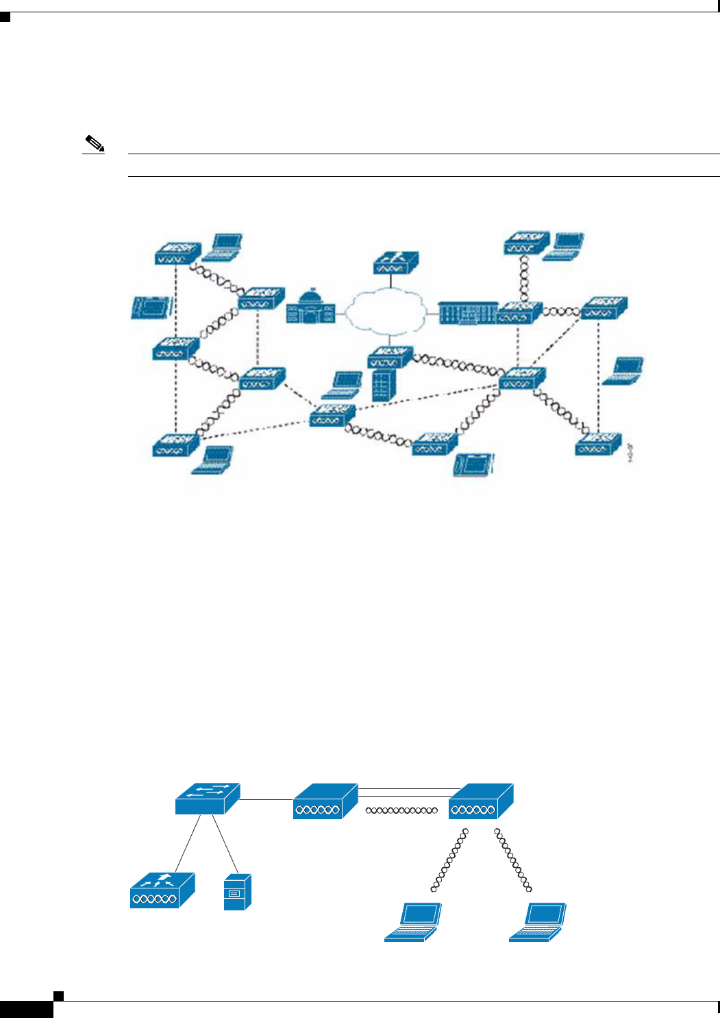
9-6
Cisco Wireless LAN Controller Configuration Guide
OL-21524-02
Chapter 9 Controlling Mesh Access Points
Cisco Aironet Mesh Access Points
Some of the buildings have onsite controllers to terminate CAPWAP sessions from the mesh access
points but it is not a mandatory requirement because CAPWAP sessions can be back hauled to a
controller over a wide-area network (WAN) (see Figure 9-3).
Note For more details on CAPWAP, see the “Architecture Overview” section on page 9-12.
Figure 9-2 Wireless Mesh Deployment
Wireless Backhaul
In a Cisco wireless backhaul network, traffic can be bridged between MAPs and RAPs. This traffic can
be from wired devices that are being bridged by the wireless mesh or CAPWAP traffic from the mesh
access points. This traffic is always AES encrypted when it crosses a wireless mesh link such as a
wireless backhaul (see Figure 9-3).
AES encryption is established as part of the mesh access point neighbor relationship with other mesh
access points. The encryption keys used between mesh access points are derived during the EAP
authentication process.
Only 5 GHz backhaul is possible on all mesh access points except 1522 in which either 2.4 or 5 GHz
radio can be configured as a backhaul radio (see Configuring Advanced Features, page 9-72).
Figure 9-3 Wireless Backhaul
RAP MAP
Controller WCS
AES Encrypted
Clear text
Encrypted
205683
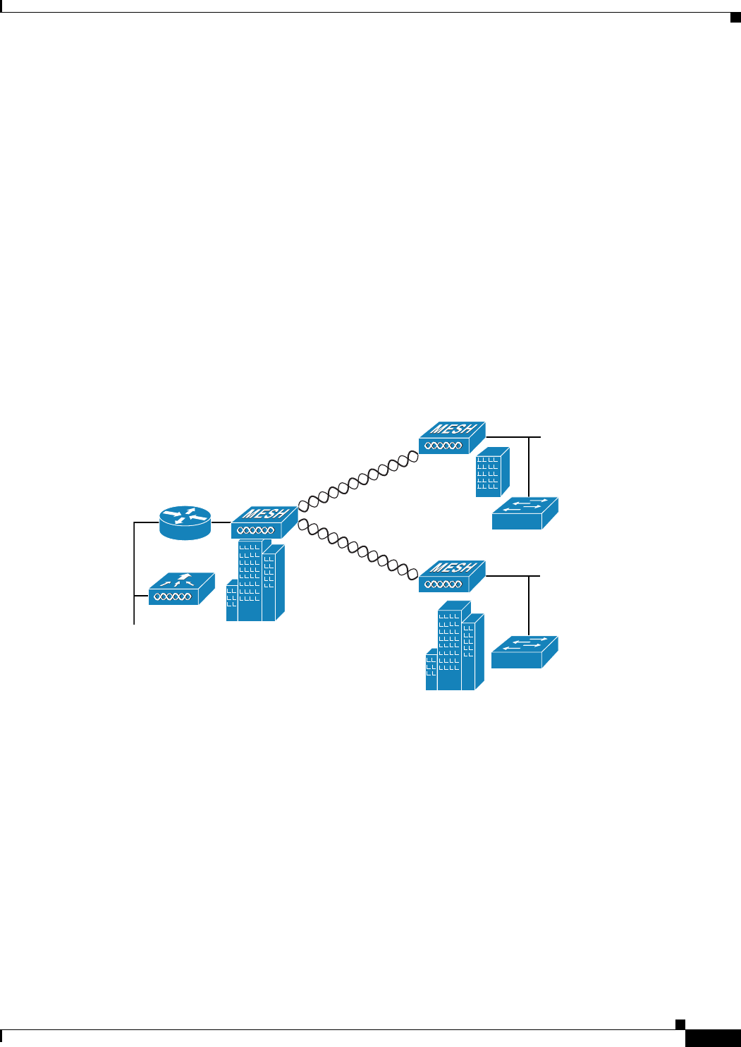
9-7
Cisco Wireless LAN Controller Configuration Guide
OL-21524-02
Chapter 9 Controlling Mesh Access Points
Cisco Aironet Mesh Access Points
Universal Access
You can configure the backhaul on mesh access points to accept client traffic over its 802.11a radio. This
feature is identified as Backhaul Client Access in the controller GUI (Monitor > Wireless). When this
feature is disabled, backhaul traffic is transmitted only over the 802.11a or 802.11a/n radio and client
association is allowed only over the 802.11b/g or 802.11b/g/n radio. For more information about the
configuration, see the “Configuring Advanced Features” section on page 9-72.
Point-to-Multipoint Wireless Bridging
In the point-to-multipoint bridging scenario, a RAP acting as a root bridge connects multiple MAPs as
nonroot bridges with their associated wired LANs. By default, this feature is disabled for all MAPs. If
Ethernet bridging is used, you must enable it on the controller for the respective MAP and for the RAP.
Figure 9-4 shows a simple deployment with one RAP and two MAPs, but this configuration is
fundamentally a wireless mesh with no WLAN clients. Client access can still be provided with Ethernet
bridging enabled, although if bridging between buildings, MAP coverage from a high rooftop might not
be suitable for client access.
Figure 9-4 Point-to-Multipoint Bridging Example
Point-to-Point Wireless Bridging
In a point-to-point bridging scenario, a 1500 Series Mesh AP can be used to extend a remote network by
using the backhaul radio to bridge two segments of a switched network (see Figure 9-5). This is
fundamentally a wireless mesh network with one MAP and no WLAN clients. Just as in
point-to-multipoint networks, client access can still be provided with Ethernet bridging enabled,
although if bridging between buildings, MAP coverage from a high rooftop might not be suitable for
client access.
If you intend to use an Ethernet bridged application, we recommend that you enable the bridging feature
on the RAP and on all MAPs in that segment. You must verify that any attached switches to the Ethernet
ports of your MAPs are not using VLAN Trunking Protocol (VTP). VTP can reconfigure the trunked
VLANs across your mesh and possibly cause a loss in connection for your RAP to its primary WLC. An
incorrect configuration can take down your mesh deployment.
148439
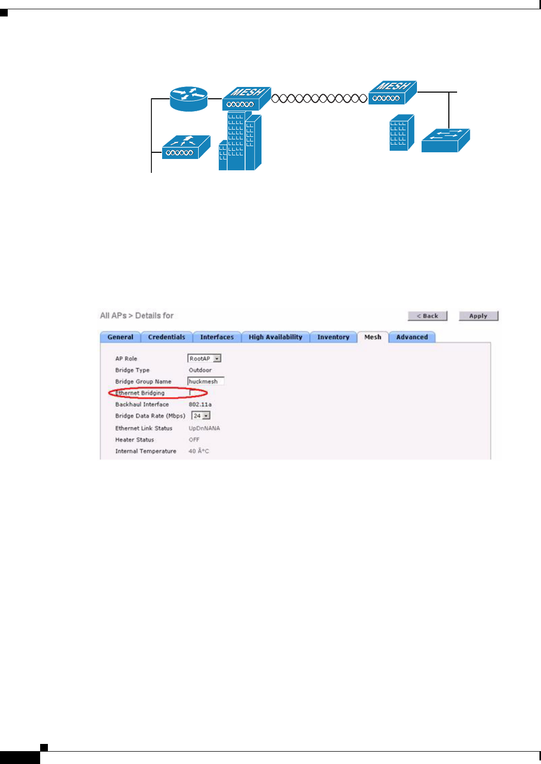
9-8
Cisco Wireless LAN Controller Configuration Guide
OL-21524-02
Chapter 9 Controlling Mesh Access Points
Cisco Aironet Mesh Access Points
Figure 9-5 Point-to-Point Bridging Example
For security reasons the Ethernet port on the MAPs is disabled by default. It can be enabled only by
configuring Ethernet Bridging on the Root and the respective MAPs (see Figure 9-6).
Ethernet bridging has to be enabled for the following two scenarios:
1. When you want to use the mesh nodes as bridges.
2. When you want to connect Ethernet devices such as a video camera on the MAP using its Ethernet
port.
Figure 9-6 Wireless > All APs > Details
Ensure that you enable Ethernet bridging for every parent mesh AP taking the path from the mesh AP in
question to the controller. For example, if you enable Ethernet bridging on MAP2 in Hop 2, then you
must also enable Ethernet bridging on MAP1 (parent MAP), and on the RAP connecting to the controller.
Range Parameters have to be configured for longer links under the Wireless > Mesh tab. Optimum
distance (in feet) should exist between the root access point (RAP) and the farthest mesh access point
(MAP). Range from the RAP bridge to the MAP bridge has to be mentioned in feet (see Figure 9-7).
148440

9-9
Cisco Wireless LAN Controller Configuration Guide
OL-21524-02
Chapter 9 Controlling Mesh Access Points
Cisco Aironet Mesh Access Points
Figure 9-7 Configuring Range Parameters
The following global parameter applies to all mesh access points when they join the controller and all
existing mesh access points in the network:
Range: 150 to 132,000 feet
Default: 12,000 feet
Configuring Mesh Range Using the CLI
To configure the distance between the nodes doing the bridging, use the config mesh range command
(see Figure 9-9). Figure 9-8 shows how to display the mesh range by entering the show mesh config
command.
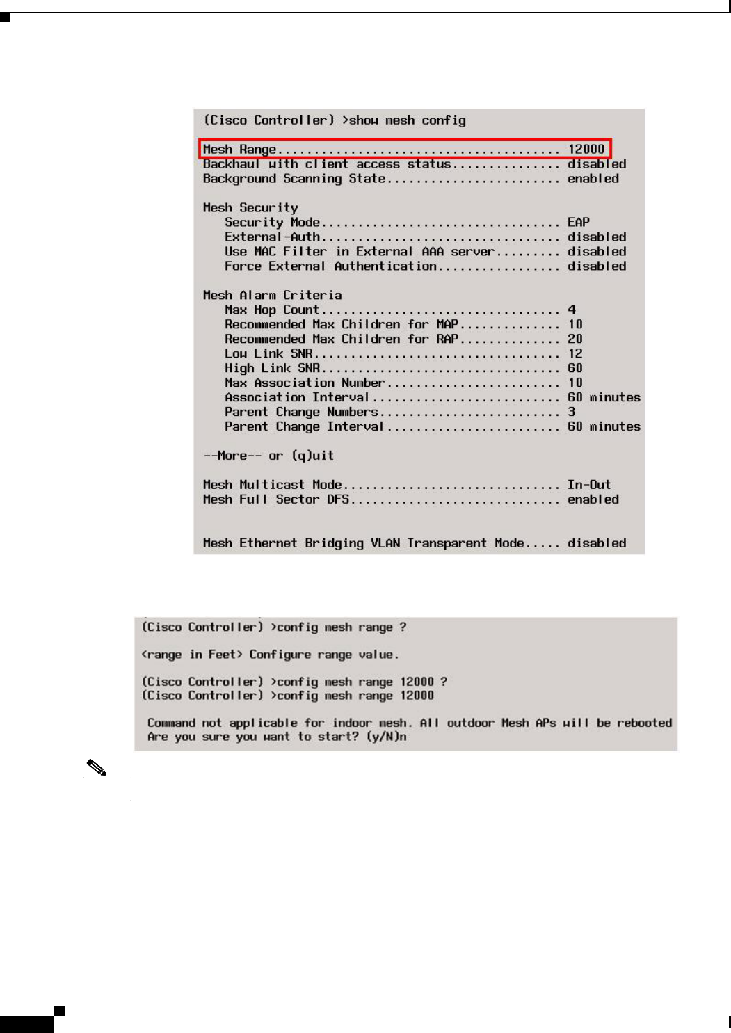
9-10
Cisco Wireless LAN Controller Configuration Guide
OL-21524-02
Chapter 9 Controlling Mesh Access Points
Cisco Aironet Mesh Access Points
Figure 9-8 Displaying Mesh Range Details
Figure 9-9 Configuring Mesh Range
Note APs reboot after you specify the range.

9-11
Cisco Wireless LAN Controller Configuration Guide
OL-21524-02
Chapter 9 Controlling Mesh Access Points
Cisco Aironet Mesh Access Points
Note To estimate the range, you can use range calculators that are available at:
Cisco 1520 Series Outdoor Mesh Range Calculation Utility:
http://www.cisco.com/en/US/products/ps8368/products_implementation_design_guides_list.html
Range Calculator for 1550 Series Outdoor Mesh Access Points:
http://www.cisco.com/en/US/products/ps11451/products_implementation_design_guides_list.html
Assumptions for AP1522 Range Calculator
• The AP1522 Range Calculator has been edited to stay within limitations for Tx power and EIRP
under the listed regulatory domains. There may be cases where it exceeds the limitations. You must
verify that the installation is within the laws of the location in which it is being installed.
• When you use the AP1522 Range Calculator, available power levels change based upon the
regulatory domain, the antenna (or antenna gain) selected, the modulation mode, which is based on
the data rate selected (OFDM requires a lower power level in some domains). You must verify all
parameters after making any parameter changes.
• Rx sensitivity in 2.4 GHz is the composite sensitivity of all three Rx paths. That is, MRC is included
in 2.4 GHz. There is only one Rx for 5 GHz.
• You can choose only the channels that the access point is certified for.
• You can select only valid power levels.
Assumptions for AP1552 Range Calculator
• The AP1552 Range Calculator has been edited to stay within limitations for Tx power and EIRP
under the listed regulatory domains. There may be cases where it exceeds the limitations. You must
verify that the installation is within the laws of the location in which it is being installed.
• All three antenna ports must be used for external antenna models of 1552 for effective performance.
Otherwise, range is significantly compromised. 1552 radios have two Tx paths and three Rx paths.
• The Tx power is the total composite power of both Tx paths.
• Rx sensitivity is the composite sensitivity of all three Rx paths. That is, MRC is included.
• The AP1552 Range Calculator assumes that ClientLink (Beamforming) is switched on.
• When you use the AP1552 Range Calculator, available power levels change based upon the
regulatory domain, the antenna (or antenna gain) selected, and the data rate selected. You must
verify all parameters after making any parameter changes.
• You can select a different antenna than the two that are available by default. If you enter a high gain
antenna and choose a power that goes over the EIRP limit, then you get a warning and the range
equals 0.
• You can choose only the channels that the access point is certified for.
• You can only select only valid power levels.

9-12
Cisco Wireless LAN Controller Configuration Guide
OL-21524-02
Chapter 9 Controlling Mesh Access Points
Architecture Overview
Architecture Overview
This section describes the mesh architecture overview.
CAPWAP
CAPWAP is the provisioning and control protocol used by the controller to manage access points (mesh
and nonmesh) in the network. This protocol replaces LWAPP in controller software 5.2 or later releases.
Cisco Adaptive Wireless Path Protocol Wireless Mesh Routing
The Cisco Adaptive Wireless Path Protocol (AWPP) is designed specifically for wireless mesh
networking. The path decisions of AWPP are based on the link quality and the number of hops.
Ease of deployment, fast convergence, and minimal resource consumption are also key components of
AWPP.
The goal of AWPP is to find the best path back to a RAP for each MAP that is part of the RAP’s bridge
group. To do this, the MAP actively solicits for neighbor MAPs. During the solicitation, the MAP learns
all of the available neighbors back to a RAP, determines which neighbor offers the best path, and then
synchronizes with that neighbor.
Mesh Neighbors, Parents, and Children
Relationships among access points with the mesh network are labeled as parent, child, or neighbor
(see Figure 9-10) as follows:
• A parent access point offers the best route back to the RAP based on its ease values. A parent can
be either the RAP itself or another MAP. Ease is calculated using the SNR and link hop value of
each neighbor. Given multiple choices, an access point with a higher ease value is selected.
• A child access point selects the parent access point as its best route back to the RAP.
• A neighbor access point is within the radio frequency (RF) range of another access point but is not
selected as its parent or a child because its ease values are lower than that of the parent.
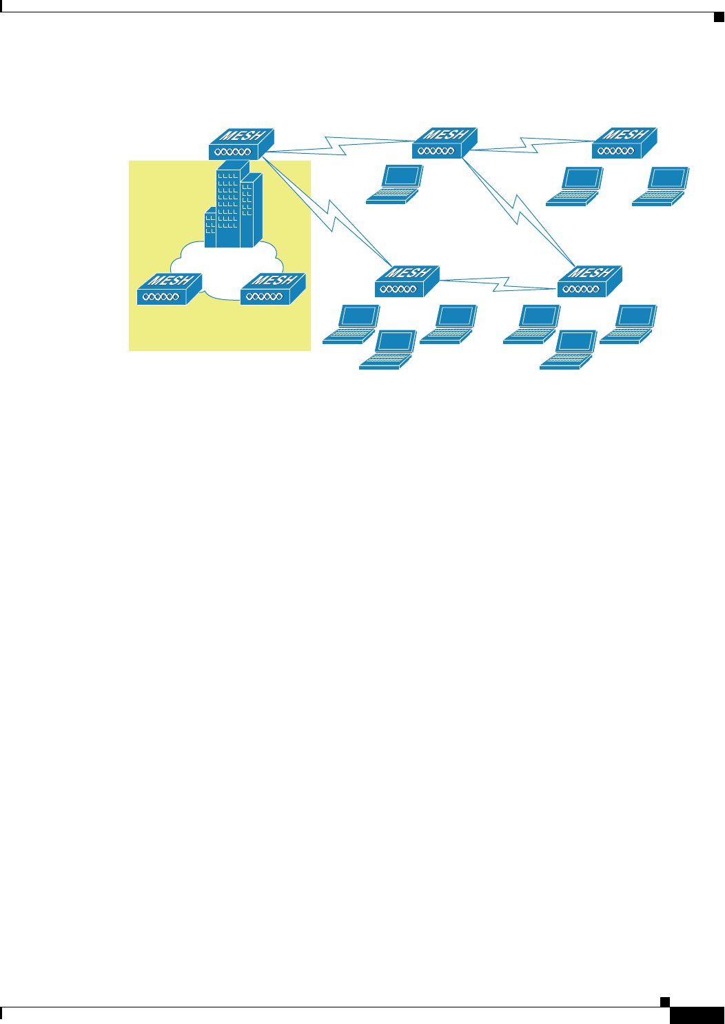
9-13
Cisco Wireless LAN Controller Configuration Guide
OL-21524-02
Chapter 9 Controlling Mesh Access Points
Architecture Overview
Figure 9-10 Parent, Child, and Neighbor Access Points
Wireless Mesh Constraints
The following are a few system characteristics to consider when you design and build a wireless mesh
network. Some of these characteristics apply to the backhaul network design and others to the CAPWAP
controller design:
Wireless Backhaul Data Rate
Backhaul is used to create only the wireless connection between the access points. The backhaul
interface by default is 802.11a or 802.11a/n depending upon the access point. The rate selection is
important for effective use of the available RF spectrum. The rate can also affect the throughput of client
devices, and throughput is an important metric used by industry publications to evaluate vendor devices.
Dynamic Rate Adaptation (DRA) introduces a process to estimate optimal transmission rate for packet
transmissions. It is important to select rates correctly. If the rate is too high, packet transmissions fail
resulting in communication failure. If the rate is too low, the available channel bandwidth is not used,
resulting in inferior products, and the potential for catastrophic network congestion and collapse.
Data rates also affect the RF coverage and network performance. Lower data rates, for example 6 Mbps,
can extend farther from the access point than can higher data rates, for example 300 Mbps. As a result,
the data rate affects cell coverage and consequently the number of access points required. Different data
rates are achieved by sending a more redundant signal on the wireless link, allowing data to be easily
recovered from noise. The number of symbols sent out for a packet at the 1-Mbps data rate is higher than
the number of symbols used for the same packet at 11 Mbps. Therefore, sending data at the lower bit
rates takes more time than sending the equivalent data at a higher bit rate, resulting in reduced
throughput.
A lower bit rate might allow a greater distance between MAPs, but there are likely to be gaps in the
WLAN client coverage, and the capacity of the backhaul network is reduced. An increased bit rate for
the backhaul network either requires more MAPs or results in a reduced SNR between MAPs, limiting
mesh reliability and interconnection. For more information about configuring wireless backhaul data
rate, see “Configuring Wireless Backhaul Data Rate” section on page 9-48.
148446
LAN
RAP
Building 1
Parent
Rooftop:d6:80
Child
Mesh:7a:70
MAP
MAP
Neighbor
Mesh:78:90
MAP
MAP

9-14
Cisco Wireless LAN Controller Configuration Guide
OL-21524-02
Chapter 9 Controlling Mesh Access Points
Architecture Overview
Note The data rate can be set on the backhaul on a per AP basis. It is not a global command.
The required minimum LinkSNR for backhaul links per data rate is shown in Table 9-1.
• The required minimum LinkSNR value is driven by the data rate and the following formula:
Minimum SNR + fade margin.
Table 9-2 summarizes the calculation by data rate.
–
Minimum SNR refers to an ideal state of noninterference, nonnoise, and a system packet error
rate (PER) of no more than 10 percent.
–
Typical fade margin is approximately 9 to 10 dB.
• If we take into account the effect of MRC for calculating Minimum Required Link SNR. Table 9-3
shows the required LinkSNR for 802.11a/g (2.4 GHz and 5 GHz) for AP1552 and 1522 with 3 Rx
antennas (MRC gain).
LinkSNR = Minimum SNR - MRC + Fade Margin (9 dB)
Ta b l e 9-1 Backhaul Data Rates and Minimum LinkSNR Requirements
802.11a Data Rate (Mbps) Minimum Required LinkSNR (dB)
54 31
48 29
36 26
24 22
18 18
12 16
915
614
Ta b l e 9-2 Minimum Required LinkSNR Calculations by Data Rate
802.11n Date Rate
(Mbps) Minimum SNR (dB) + Fade Margin =
Minimum Required
LinkSNR (dB)
65914
96915
12 7916
18 9918
24 13 922
36 17 926

9-15
Cisco Wireless LAN Controller Configuration Guide
OL-21524-02
Chapter 9 Controlling Mesh Access Points
Architecture Overview
If we consider only 802.11n rates, then Table 9-4 shows LinkSNR requirements with AP1552 for 2.4 and
5 GHz.
Note With two spatial streams, the MRC gain is halved, that is the MRC gain is reduced by 3 dB. This is
because the system has 10 log (3/2 SS) instead of 10 log (3/1 SS). If there were to have been 3 SS with
3 RX, then the MRC gain would have been zero.
Ta b l e 9-3 Required LinkSNR Calculations for 802.11a/g
802.11a/g MCS
(Mbps) Modulation
Minimum SNR
(dB)
MRC Gain from
3 RXs (dB)
Fade Margin
(dB)
Required Link
SNR (dB)
6BPSK 1/2 54.7 99.3
9BPSK 3/4 64.7 910.3
12 QPSK 1/2 74.7 911.3
18 QPSK 3/4 94.7 913.3
24 16QAM 1/2 13 4.7 917.3
36 16QAM 3/4 17 4.7 921.3
48 64QAM 2/3 20 4.7 924.3
54 64QAM 3/4 22 4.7 926.3
Ta b l e 9-4 Requirements for LinkSNR with AP1552 for 2.4 and 5 GHz
No. of
Spatial
Streams 11n MCS Modulation
Minimum SNR
(dB)
MRC Gain from
3 RXs (dB)
Fade Margin
(dB)
Link SNR
(dB)
1MCS 0 BPSK 1/2 54.7 99.3
1MCS 1 QPSK 1/2 74.7 911.3
1MCS 2 QPSK 3/4 94.7 913.3
1MCS 3 16QAM 1/2 13 4.7 917.3
1MCS 4 16QAM 3/4 17 4.7 921.3
1MCS 5 64QAM 2/3 20 4.7 924.3
1MCS 6 64QAM 3/4 22 4.7 926.3
1MCS 7 64QAM 5/6 23 4.7 927.3
2MCS 8 BPSK 1/2 51.7 912.3
2MCS 9 QPSK 1/2 71.7 914.3
2MCS 10 QPSK 3/4 91.7 916.3
2MCS 11 16QAM 1/2 13 1.7 920.3
2MCS 12 16QAM 3/4 17 1.7 924.3
2MCS 13 64QAM 2/3 20 1.7 927.3
2MCS 14 64QAM 3/4 22 1.7 929.3
2MCS 15 64QAM 5/6 23 1.7 930.3

9-16
Cisco Wireless LAN Controller Configuration Guide
OL-21524-02
Chapter 9 Controlling Mesh Access Points
Architecture Overview
• Number of backhaul hops is limited to eight but we recommend three to four hops.
The number of hops is recommended to be limited to three or four primarily to maintain sufficient
backhaul throughput, because each mesh access point uses the same radio for transmission and
reception of backhaul traffic, which means that throughput is approximately halved over every hop.
For example, the maximum throughput for 24 Mbps is approximately 14 Mbps for the first hop,
9 Mbps for the second hop, and 4 Mbps for the third hop.
• Number of MAPs per RAP.
There is no current software limitation on how many MAPs per RAP you can configure. However,
it is suggested that you limit the number to 20 MAPs per RAP.
• Number of controllers
–
The number of controllers per mobility group is limited to 72.
• Number of mesh access points supported per controller. For more information, see the “Controller
Planning” section.
ClientLink Technology
Many networks still support a mix of 802.11a/g and 802.11n clients. Because 802.11a/g clients (legacy
clients) operate at lower data rates, the older clients can reduce the capacity of the entire network.
Cisco’s ClientLink technology can help solve problems related to adoption of 802.11n in mixed-client
networks by ensuring that 802.11a/g clients operate at the best possible rates, especially when they are
near cell boundaries.
Advanced signal processing has been added to the Wi-Fi chipset. Multiple transmit antennas are used to
focus transmissions in the direction of the 802.11a/g client, increasing the downlink signal-to-noise ratio
and the data rate over range, thereby reducing coverage holes and enhancing the overall system
performance. This technology learns the optimum way to combine the signal received from a client and
then uses this information to send packets in an optimum way back to the client. This technique is also
referred to as MIMO (multiple-input multiple-output) beamforming, transmit beamforming, or
cophasing, and it is the only enterprise-class and service provider-class solution in the market that does
not require expensive antenna arrays.
The 802.11n systems take advantage of multipath by sending multiple radio signals simultaneously.
Each of these signals, called a spatial stream, is sent from its own antenna using its own transmitter.
Because there is some space between these antennas, each signal follows a slightly different path to the
receiver, a situation called spatial diversity. The receiver has multiple antennas as well, each with its own
radio that independently decodes the arriving signals, and each signal is combined with signals from the
other receiver radios. This results in multiple data streams receiving at the same time. This enables a
higher throughput than previous 802.11a/g systems, but requires an 802.11n capable client to decipher
the signal. Therefore, both AP and client need to support this capability. Due to the complexity of issues,
in the first generation of mainstream 802.11n chipsets, neither the AP nor client chipsets implemented
802.11n transmit beamforming. Therefore, the 802.11n standard transmit beamforming will be available
eventually, but not until the next generation of chipsets take hold in the market. We intend to lead in this
area going forward.
We realized that for the current generation of 802.11n APs, while the second transmit path was being
well utilized for 802.11n clients (to implement spatial diversity), it was not being fully used for
802.11a/g clients. In other words, for 802.11 a/g clients, some of the capabilities of the extra transmit
path was lying idle. In addition, we realized that for many networks, the performance of the installed
802.11 a/g client base would be a limiting factor on the network.

9-17
Cisco Wireless LAN Controller Configuration Guide
OL-21524-02
Chapter 9 Controlling Mesh Access Points
Architecture Overview
To take advantage of this fallow capacity and greatly enhance overall network capacity by bringing
802.11 a/g clients up to a higher performance level, we created an innovation in transmit beamforming
technology, called ClientLink.
ClientLink uses advanced signal processing techniques and multiple transmit paths to optimize the
signal received by 802.11a/g clients in the downlink direction without requiring feedback. Because no
special feedback is required, Cisco ClientLink works with all existing 802.11a/g clients.
Cisco ClientLink technology effectively enables the access point to optimize the SNR exactly at the
position where the client is placed. ClientLink provides a gain of almost 4 dB in the downlink direction.
Improved SNR yields many benefits, such as a reduced number of retries and higher data rates. For
example, a client at the edge of the cell that might previously have been capable of receiving packets at
12 Mbps could now receive them at 36 Mbps. Typical measurements of downlink performance with
ClientLink show as much as 65 percent greater throughput for 802.11a/g clients. By allowing the Wi-Fi
system to operate at higher data rates and with fewer retries, ClientLink increases the overall capacity
of the system, which means an efficient use of spectrum resources.
ClientLink in the 1552 access points is based on ClientLink capability available in AP3500s. Therefore,
the access point has the ability to beamform well to nearby clients and to update beamforming
information on 802.11ACKs. Therefore, even if there is no dedicated uplink traffic, the ClientLink works
well, which is beneficial to both TCP and UDP traffic streams. There are no RSSI watermarks, which
the client has to cross to take advantage of this Beamforming with Cisco 802.11n access points.
ClientLink can beamform to 15 clients at a time. Therefore, the host must select the best 15 if the number
of legacy clients exceeds 15 per radio. AP1552 has two radios, which means that up to 30 clients can be
beamformed in time domain.
Although ClientLink is applied to legacy OFDM portions of packets, which refers to 11a/g rates (not
11b) for both indoor and outdoor 802.11n access points, there is one difference between ClientLink for
indoor 11n and ClientLink for outdoor 11n. For indoor 11n access points, SW limits the affected rates
to 24, 36, 48, and 54 Mbps. This is done to avoid clients sticking to a far away AP in an indoor
environment. SW also does not allow ClientLink to work for those rates for 11n clients because the
throughput gain is so minimal. However, there is a demonstrable gain for pure legacy clients. For outdoor
11n access points, we do need more coverage. Thus, three more additional legacy data rates lower than
24 Mbps have been added. ClientLink for outdoors is applicable to legacy data rates of 9, 12, 18, 24, 36,
48, and 54 Mbps.
Using the GUI to Configure ClientLink
To configure ClientLink (Beamforming) using the controller GUI, follow these steps:
Step 1 Disable the 802.11a or 802.11b/g network as follows:
a. Choose Wireless > 802.11a/n or 802.11b/g/n > Network to open the 802.11a (or 802.11b/g) Global
Parameters page (see Figure 9-11).

9-18
Cisco Wireless LAN Controller Configuration Guide
OL-21524-02
Chapter 9 Controlling Mesh Access Points
Architecture Overview
Figure 9-11 802.11a Global Parameters Page
b. Unselect the 802.11a (or 802.11b/g) Network Status check box.
c. Click Apply to commit your changes.
Step 2 Select the Beamforming check box to globally enable beamforming on your 802.11a or 802.11g
network, or leave it unselected to disable this feature. The default value is disabled.
Step 3 Reenable the network by selecting the 802.11a (or 802.11b/g) Network Status check box.
Step 4 Click Apply to commit your changes.
Step 5 Click Save Configuration to save your changes.
Note After you enable beamforming on the network, it is automatically enabled for all the radios
applicable to that network type.
Step 6 Override the global configuration and enable or disable Beamforming for a specific access point as
follows:
a. Choose Wireless > Access Points > Radios > 802.11a/n or 802.11b/g/n to open the 802.11a/n (or
802.11b/g/n) Radios page.
b. Hover your cursor over the blue drop-down arrow for the access point for which you want to modify
the radio configuration and choose Configure. The 802.11a/n (or 802.11b/g/n) Cisco APs >
Configure page appears (see Figure 9-12).
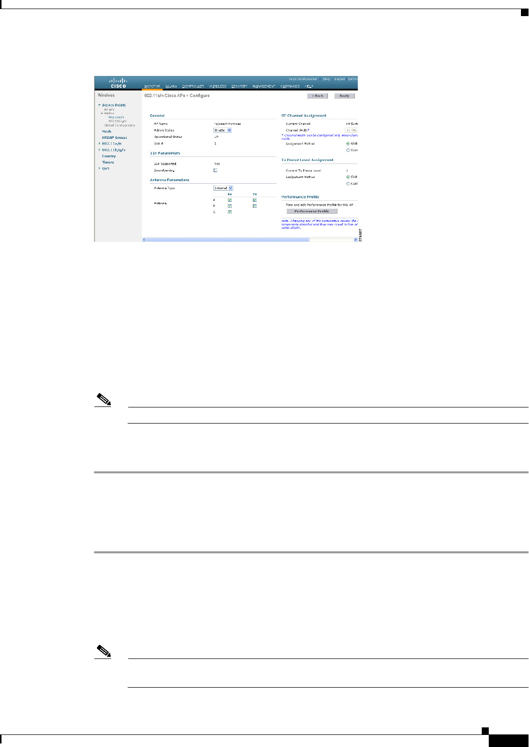
9-19
Cisco Wireless LAN Controller Configuration Guide
OL-21524-02
Chapter 9 Controlling Mesh Access Points
Architecture Overview
Figure 9-12 802.11a/n Cisco APs > Configure Page
Step 7 In the 11n Parameters section, select the Beamforming check box to enable beamforming for this access
point or leave it unselected to disable this feature. The default value is unselected if beamforming is
disabled on the network and selected if beamforming is enabled on the network.
Note If the access point does not support 802.11n, the beamforming option is not available.
Step 8 Click Apply to commit your changes.
Step 9 Click Save Configuration to save your changes.
Using the CLI to Configure ClientLink
To configure ClientLink (Beamforming) using the controller CLI, follow these steps:
Step 1 Disable the 802.11a or 802.11b/g network by entering this command:
config {802.11a | 802.11b} disable network
Step 2 Globally enable or disable beamforming on your 802.11a or 802.11g network by entering this command:
config {802.11a | 802.11b} beamforming global {enable | disable}
The default value is disabled.
Note After you enable beamforming on the network, it is automatically enabled for all the radios
applicable to that network type.

9-20
Cisco Wireless LAN Controller Configuration Guide
OL-21524-02
Chapter 9 Controlling Mesh Access Points
Architecture Overview
Step 3 Override the global configuration and enable or disable beamforming for a specific access point by
entering this command:
config {802.11a | 802.11b} beamforming ap Cisco_AP {enable | disable}
The default value is disabled if beamforming is disabled on the network and enabled if beamforming is
enabled on the network.
Step 4 Reenable the network by entering this command:
config {802.11a | 802.11b} enable network
Step 5 Save your changes by entering this command:
save config
Step 6 See the beamforming status for your network by entering this command:
show {802.11a | 802.11b}
Information similar to the following appears:
802.11a Network.................................. Enabled
11nSupport....................................... Enabled
802.11a Low Band........................... Enabled
802.11a Mid Band........................... Enabled
802.11a High Band.......................... Enabled
...
Pico-Cell-V2 Status.............................. Disabled
TI Threshold..................................... -50
Legacy Tx Beamforming setting................. Enabled
Step 7 See the beamforming status for a specific access point by entering this command:
show ap config {802.11a | 802.11b} Cisco_AP
Information similar to the following appears:
Cisco AP Identifier.............................. 14
Cisco AP Name.................................... 1250-1
Country code..................................... US - United States
Regulatory Domain allowed by Country............. 802.11bg:-A 802.11a:-A
...
Phy OFDM parameters
Configuration ............................. AUTOMATIC
Current Channel ........................... 149
Extension Channel ......................... NONE
Channel Width.............................. 20 Mhz
Allowed Channel List....................... 36,40,44,48,52,56,60,64,100,
......................................... 104,108,112,116,132,136,140,
......................................... 149,153,157,161,165
TI Threshold .............................. -50
Legacy Tx Beamforming Configuration ....... CUSTOMIZED
Legacy Tx Beamforming ..................... ENABLED
Commands Related to ClientLink
The following commands are related to ClientLink:
• The following commands are to be entered in the AP console:
–
To check the status of Beamforming on the AP, enter the show controller d0/d1 command.
–
To find a client in the AP rbf table, enter the show interface dot110 command.

9-21
Cisco Wireless LAN Controller Configuration Guide
OL-21524-02
Chapter 9 Controlling Mesh Access Points
Architecture Overview
–
To check the Beamforming rate assigned on the AP, enter the debug d0 trace print rates
command.
• The following commands on the AP console are used for troubleshooting:
–
To show that ClientLink is enabled on a radio, enter the show controllers | inc Beam command.
The output is displayed as follows:
Legacy Beamforming: Configured Yes, Active Yes, RSSI Threshold -50 dBm
Legacy Beamforming: Configured Yes, Active Yes, RSSI Threshold -60 dBm
–
To show that ClientLink is Beamforming to a particular client, enter the show interface
dot11radio 1 lbf rbf command.
The output is displayed as follows:
RBF Table:
Index Client MAC Reserved Valid Tx BF Aging
1 0040.96BA.45A0 Yes Yes Yes No
Controller Planning
The following items affect the number of controllers required in a mesh network:
• Mesh access points (RAPs and MAPs) in the network.
The wired network that connects the RAP and controllers can affect the total number of access
points supported in the network. If this network allows the controllers to be equally available to all
access points without any impact on WLAN performance, the access points can be evenly
distributed across all controllers for maximum efficiency. If this is not the case, and controllers are
grouped into various clusters or PoPs, the overall number of access points and coverage are reduced.
For example, you can have 72 Cisco 4400 Series Controllers in a mobility group, and each Cisco
4400 Series Controller supports 100 local access points, which gives a total number of 7200 possible
access points per mobility group.
• Number of mesh access points (RAPs and MAPs) supported per controller. See Table 9-5.
For clarity, nonmesh access points are referred to as local access points in this document.
Ta b l e 9-5 Mesh Access Point Support by Controller Model
Controller Model
Local AP
Support
(nonmesh)1
Maximum
Possible
Mesh AP
Support RAP MAP
Total
Mesh AP
Support
55082500 500 1499 500
100 400 500
150 350 500
200 300 500
44043100 150 1149 150
50 100 150
75 50 125
100 0100

9-22
Cisco Wireless LAN Controller Configuration Guide
OL-21524-02
Chapter 9 Controlling Mesh Access Points
Architecture Overview
2504450 50 149 50
248 50
545 50
941 50
21063611 110 11
2810
369
448
527
606
2112212 12 111 12
3912
6612
9312
12 012
2125225 25 124 25
520 25
10 15 25
15 10 25
20 525
25 025
WiSM3300 375 1374 375
100 275 375
250 100 350
300 0300
WiSM23500 500 1499 500
100 400 500
150 350 500
200 300 500
1. Local AP support is the total number of nonmesh APs supported on the controller model.
2. For 5508, 2112, and 2125 controllers, the number of MAPs is equal to (local AP support - number of RAPs).
3. For 4404, 2106, and WiSM controllers, the number of MAPs is equal to ((local AP support - number of RAPs) x 2), not to
exceed the maximum possible mesh AP support.
4. For 2504.
Table 9-5 Mesh Access Point Support by Controller Model (continued)
Controller Model
Local AP
Support
(nonmesh)1
Maximum
Possible
Mesh AP
Support RAP MAP
Total
Mesh AP
Support

9-23
Cisco Wireless LAN Controller Configuration Guide
OL-21524-02
Chapter 9 Controlling Mesh Access Points
Adding Mesh Access Points to the Mesh Network
Note The Wireless LAN Controller modules NM and NME now support mesh 1520 series access points from
Wireless LAN Controller (WLC) software release 5.2 and later releases.
Note Mesh is fully supported on Cisco 5508 Controllers. The Base License (LIC-CT508-Base) is sufficient
for indoor and outdoor APs (AP152X). The WPlus License (LIC-WPLUS-SW) is merged with the base
license. The WPlus License is not required for indoor mesh APs.
Mesh APs (MAPs/RAPs) are counted as full APs on Cisco 5508 Controllers.
With other controller platforms, MAPs are counted as half APs.
Data Plane Transport Layer Security (DTLS) is not supported on mesh access points.
Adding Mesh Access Points to the Mesh Network
This section assumes that the controller is already active in the network and is operating in Layer 3 mode.
Note Controller ports that the mesh access points connect to should be untagged.
Before adding a mesh access point to a network, do the following:
1. Add the MAC address of the mesh access point to the controller’s MAC filter. See the “Adding MAC
Addresses of Mesh Access Points to MAC Filter” section on page 9-24.
2. Define the role (RAP or MAP) for the mesh access point. See the “Defining Mesh Access Point
Role” section on page 9-26.
3. Verify that Layer 3 is configured on the controller. See the “Verifying Layer 3 Configuration”
section on page 9-27.
4. Configure a primary, secondary, and tertiary controller for each mesh access point. See the
“Configuring Multiple Controllers Using DHCP 43 and DHCP 60” section on page 9-27.
a. Configure a backup controller. See the “Configuring Backup Controllers” procedure on
page 9-28.
5. Configure external authentication of MAC addresses using an external RADIUS server. See the
“Configuring External Authentication and Authorization Using a RADIUS Server” section on
page 9-33.
6. Configure global mesh parameters. See the “Configuring Global Mesh Parameters” section on
page 9-35.
7. Configure universal client access. See the “Configuring Advanced Features” section on page 9-72.
8. Configure local mesh parameters. See the “Configuring Local Mesh Parameters” section on
page 9-47.
9. Configure antenna parameters. See the “Configuring Antenna Gain” section on page 9-63.
10. Configure channels for serial backhaul. This step is applicable only to serial backhaul access points.
See the “Backhaul Channel Deselection on Serial Backhaul Access Point” section on page 9-64.

9-24
Cisco Wireless LAN Controller Configuration Guide
OL-21524-02
Chapter 9 Controlling Mesh Access Points
Adding Mesh Access Points to the Mesh Network
11. Configure the DCA channels for the mesh access points. See the “Configuring Dynamic Channel
Assignment” section on page 9-69 for details.
12. Configure mobility groups (if desired) and assign controllers. See Chapter 12, “Configuring
Mobility Groups” in the Cisco Wireless LAN Controller Configuration Guide, Release 5.2 at:
http://www.cisco.com/en/US/products/ps6366/products_installation_and_configuration_guides_list.html
13. Configure Ethernet bridging (if desired). See the “Configuring Ethernet Bridging” section on
page 9-52.
14. Configure advanced features such as Ethernet VLAN tagging network, video, and voice. See the
“Configuring Advanced Features” section on page 9-72.
Adding MAC Addresses of Mesh Access Points to MAC Filter
You must enter the MAC address for all mesh access points that you want to use in the mesh network
into the appropriate controller. A controller only responds to discovery requests from outdoor radios that
appear in its authorization list. MAC filtering is enabled by default on the controller, so only the MAC
addresses need to be configured. If the access point has an SSC and has been added to the AP
Authorization List, then the MAC address of the AP does not need to be added to the MAC Filtering List.
You can add the mesh access point using either the GUI or the CLI.
Note You can also download the list of mesh access point MAC addresses and push them to the controller
using Cisco WCS. See the Cisco Wireless Control System Configuration Guide, Release 7.0.172.0:
http://www.cisco.com/en/US/docs/wireless/wcs/7.0MR1/configuration/guide/WCS70MR1.html
Adding the MAC Address of the Mesh Access Point to the Controller Filter List Using the GUI
To add a MAC filter entry for the mesh access point on the controller using the controller GUI, follow
these steps.
Step 1 Choose Security > AAA > MAC Filtering. The MAC Filtering page appears (see Figure 9-13).
Figure 9-13 MAC Filtering Page
Step 2 Click New. The MAC Filters > New page appears (see Figure 14).

9-25
Cisco Wireless LAN Controller Configuration Guide
OL-21524-02
Chapter 9 Controlling Mesh Access Points
Adding Mesh Access Points to the Mesh Network
Figure 14 MAC Filters > New Page
Step 3 Enter the MAC address of the mesh access point.
Note For 1500 series outdoor mesh access points, specify the BVI MAC address of the mesh access
point into the controller as a MAC filter. For indoor mesh access points, enter the Ethernet MAC.
If the required MAC address does not appear on the exterior of the mesh access point, enter the
following command at the access point console to display the BVI and Ethernet MAC addresses:
sh int | i Hardware.
Step 4 From the Profile Name drop-down list, select Any WLAN.
Step 5 In the Description field, specify a description of the mesh access point. The text that you enter identifies
the mesh access point on the controller.
Note You might want to include an abbreviation of its name and the last few digits of the MAC
address, such as ap1522:62:39:10. You can also note details on its location such as roof top, pole
top, or its cross streets.
Step 6 From the Interface Name drop-down list, choose the controller interface to which the mesh access point
is to connect.
Step 7 Click Apply to commit your changes. The mesh access point now appears in the list of MAC filters on
the MAC Filtering page.
Step 8 Click Save Configuration to save your changes.
Step 9 Repeat this procedure to add the MAC addresses of additional mesh access points to the list.
Adding the MAC Address of the Mesh Access Point to the Controller Filter List Using the CLI
To add a MAC filter entry for the mesh access point on the controller using the controller CLI, follow
these steps:
Step 1 To add the MAC address of the mesh access point to the controller filter list, enter this command:
config macfilter add ap_mac wlan_id interface [description]
A value of zero (0) for the wlan_id parameter specifies any WLAN, and a value of zero (0) for the
interface parameter specifies none. You can enter up to 32 characters for the optional description
parameter.
Step 2 To save your changes, enter this command:
save config

9-26
Cisco Wireless LAN Controller Configuration Guide
OL-21524-02
Chapter 9 Controlling Mesh Access Points
Adding Mesh Access Points to the Mesh Network
Defining Mesh Access Point Role
By default, AP1500s are shipped with a radio role set to MAP. You must reconfigure a mesh access point
to act as a RAP.
General Notes about MAP and RAP Association With The Controller
The general notes are as follows:
• A MAP always sets the Ethernet port as the primary backhaul if it is UP, and secondarily the
802.11a/n radio. This gives the network administrator time to reconfigure the mesh access point as
a RAP, initially. For faster convergence on the network, we recommend that you do not connect any
Ethernet device to the MAP until it has joined the mesh network.
• A MAP that fails to connect to a controller on a UP Ethernet port, sets the 802.11a/n radio as the
primary backhaul. If a MAP fails to find a neighbor or fails to connect to a controller through a
neighbor, the Ethernet port is set as the primary backhaul again.
• A MAP connected to a controller over an Ethernet port does not build a mesh topology (unlike a
RAP).
• A RAP always sets the Ethernet port as the primary backhaul.
• If the Ethernet port is DOWN on a RAP, or a RAP fails to connect to a controller on a UP Ethernet
port, the 802.11a/n radio is set as the primary backhaul for 15 minutes. Failing to find a neighbor or
failing to connect to a controller via any neighbor on the 802.11a/n radio causes the primary
backhaul to go into the scan state. The primary backhaul begins its scan with the Ethernet port.
Configuring the AP Role Using the GUI
To configure the role of a mesh access point using the GUI, follow these steps:
Step 1 Click Wireless to open the All APs page.
Step 2 Click the name of an access point. The All APs > Details (General) page appears.
Step 3 Click the Mesh tab (see Figure 9-15).
Figure 9-15 All APs > Details for (Mesh) Page
Step 4 Choose RootAP or MeshAP from the AP Role drop-down list.
Step 5 Click Apply to commit your changes and to cause the access point to reboot.

9-27
Cisco Wireless LAN Controller Configuration Guide
OL-21524-02
Chapter 9 Controlling Mesh Access Points
Adding Mesh Access Points to the Mesh Network
Configuring the AP Role Using the CLI
To configure the role of a mesh access point using the CLI, enter the following command:
config ap role {rootAP | meshAP} Cisco_AP
Verifying Layer 3 Configuration
Verify that the initial controller that the mesh access point is to associate with is at Layer 3.
To verify that the controller is configured for Layer 3, follow these steps:
Step 1 Open your web browser and enter the IP address of your controller. Be sure to precede the IP address
with https://. A login page appears.
Step 2 Specify your username and password.
The default case-sensitive username and password are admin and admin. The summary page appears.
Step 3 From the top menu bar, click Controller. The controller general page appears.
Step 4 Verify that the CAPWAP Transport Modes is set to Layer 3. If it is not, change it to Layer 3 and click
Apply.
Step 5 Save the changes, if any.
Step 6 From the menu bar, click Monitor to return to the Monitor summary page.
Step 7 See the “Configuring Multiple Controllers Using DHCP 43 and DHCP 60” section on page 9-27 to
assign a primary, secondary, and tertiary controller.
Configuring Multiple Controllers Using DHCP 43 and DHCP 60
To configure DHCP Option 43 and 60 for mesh access points in the embedded Cisco IOS DHCP server,
follow these steps:
Step 1 Enter configuration mode at the Cisco IOS CLI.
Step 2 Create the DHCP pool, including the necessary parameters such as the default router and name server. The
commands used to create a DHCP pool are as follows:
ip dhcp pool pool name
network IP Network Netmask
default-router Default router
dns-server DNS Server
where:
pool name is the name of the DHCP pool, such as AP1520
IP Network is the network IP address where the controller resides, such as 10.0.15.1
Netmask is the subnet mask, such as 255.255.255.0
Default router is the IP address of the default router, such as 10.0.0.1
DNS Server is the IP address of the DNS server, such as 10.0.10.2
Step 3 Add the option 60 line using the following syntax:
option 60 ascii “VCI string”
For the VCI string, use one of the values below. The quotation marks must be included.

9-28
Cisco Wireless LAN Controller Configuration Guide
OL-21524-02
Chapter 9 Controlling Mesh Access Points
Adding Mesh Access Points to the Mesh Network
For Cisco 1550 series access points, enter “Cisco AP c1550”
For Cisco 1520 series access points, enter “Cisco AP c1520”
For Cisco 1240 series access points, enter “Cisco AP c1240”
For Cisco 1130 series access points, enter “Cisco AP c1130”
Step 4 Add the option 43 line using the following syntax:
option 43 hex hex string
The hex string is assembled by concatenating the TLV values shown below:
Type + Length + Val u e
Type is always f1(hex). Length is the number of controller management IP addresses times 4 in hex.
Va l u e is the IP address of the controller listed sequentially in hex.
For example, suppose that there are two controllers with management interface IP addresses
10.126.126.2 and 10.127.127.2. The type is f1(hex). The length is 2 * 4 = 8 = 08 (hex). The IP addresses
translate to 0a7e7e02 and 0a7f7f02. Assembling the string then yields f1080a7e7e020a7f7f02.
The resulting Cisco IOS command added to the DHCP scope is listed below:
option 43 hex f1080a7e7e020a7f7f02
Configuring Backup Controllers
A single controller at a centralized location can act as a backup for mesh access points when they lose
connectivity with the primary controller in the local region. Centralized and regional controllers need
not be in the same mobility group. Using the controller GUI or CLI, you can specify the IP addresses of
the backup controllers, which allows the mesh access points to fail over to controllers outside of the
mobility group.
You can also configure primary and secondary backup controllers (which are used if primary, secondary,
or tertiary controllers are not specified or are not responsive) for all access points connected to the
controller as well as various timers, including the heartbeat timer and discovery request timers.
Note The fast heartbeat timer is not supported on mesh access points. The fast heartbeat timer is only
configured on access points in local and hybrid-REAP modes.
The mesh access point maintains a list of backup controllers and periodically sends primary discovery
requests to each entry on the list. When the mesh access point receives a new discovery response from
a controller, the backup controller list is updated. Any controller that fails to respond to two consecutive
primary discovery requests is removed from the list. If the mesh access point’s local controller fails, it
chooses an available controller from the backup controller list in this order: primary, secondary, tertiary,
primary backup, and secondary backup. The mesh access point waits for a discovery response from the
first available controller in the backup list and joins the controller if it receives a response within the
time configured for the primary discovery request timer. If the time limit is reached, the mesh access
point assumes that the controller cannot be joined and waits for a discovery response from the next
available controller in the list.
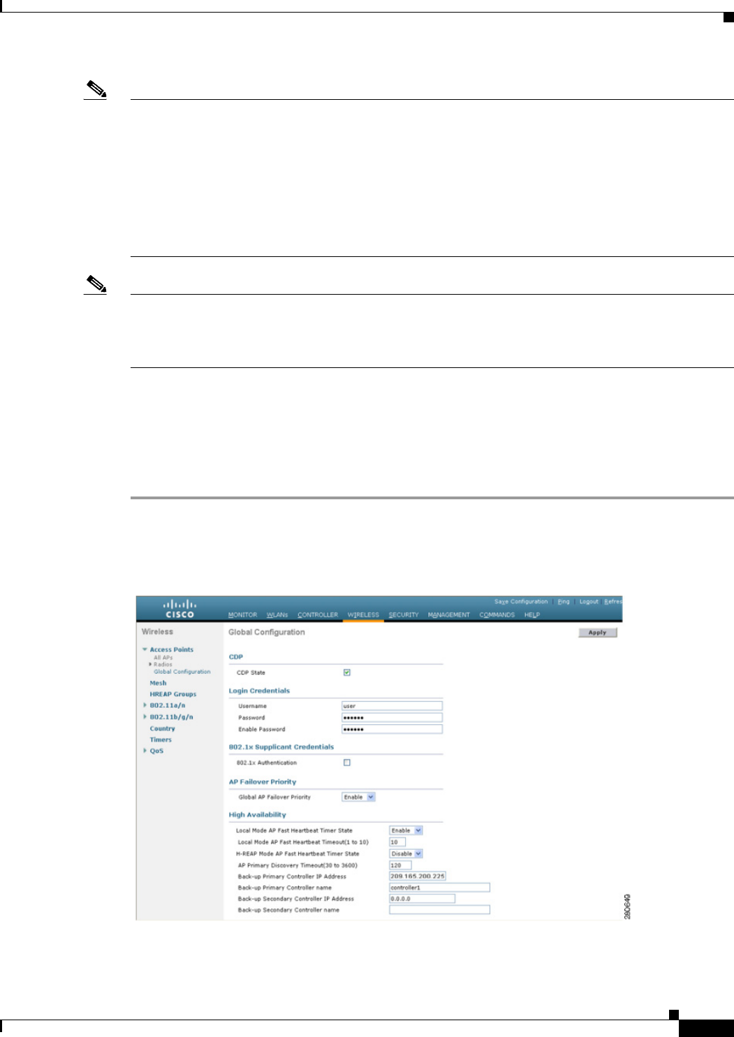
9-29
Cisco Wireless LAN Controller Configuration Guide
OL-21524-02
Chapter 9 Controlling Mesh Access Points
Adding Mesh Access Points to the Mesh Network
Note When a mesh access point’s primary controller comes back online, the mesh access point disassociates
from the backup controller and reconnects to its primary controller. The mesh access point falls back to
its primary controller and not to any secondary controller for which it is configured. For example, if a
mesh access point is configured with primary, secondary, and tertiary controllers, it fails over to the
tertiary controller when the primary and secondary controllers become unresponsive and waits for the
primary controller to come back online so that it can fall back to the primary controller. The mesh access
point does not fall back from the tertiary controller to the secondary controller if the secondary controller
comes back online; it stays connected to the tertiary controller until the primary controller comes back
up.
Note If you inadvertently configure a controller that is running software release 6.0 with a failover controller
that is running a different software release (such as 4.2, 5.0, 5.1, or 5.2), the mesh access point might
take a long time to join the failover controller because the mesh access point starts the discovery process
in LWAPP and then changes to CAPWAP discovery.
Configuring Backup Controllers Using the GUI
Using the controller GUI, follow these steps to configure primary, secondary, and tertiary controllers for
a specific mesh access point and to configure primary and secondary backup controllers for all mesh
access points:
Step 1 Choose Wireless > Access Points > Global Configuration to open the Global Configuration page. (See
Figure 9-16.)
Figure 9-16 Global Configuration Page
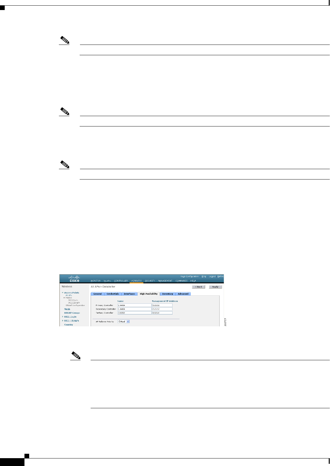
9-30
Cisco Wireless LAN Controller Configuration Guide
OL-21524-02
Chapter 9 Controlling Mesh Access Points
Adding Mesh Access Points to the Mesh Network
Note The fast heartbeat timer is not supported on mesh access points.
Step 2 In the AP Primary Discovery Timeout field, enter a value between 30 and 3600 seconds (inclusive) to
configure the access point primary discovery request timer. The default value is 120 seconds.
Step 3 If you want to specify a primary backup controller for all access points, specify the IP address of the
primary backup controller in the Back-up Primary Controller IP Address field and the name of the
controller in the Back-up Primary Controller Name field.
Note The default value for the IP address is 0.0.0.0, which disables the primary backup controller.
Step 4 If you want to specify a secondary backup controller for all access points, specify the IP address of the
secondary backup controller in the Back-up Secondary Controller IP Address field and the name of the
controller in the Back-up Secondary Controller Name field.
Note The default value for the IP address is 0.0.0.0, which disables the secondary backup controller.
Step 5 Click Apply to commit your changes.
Step 6 If you want to configure primary, secondary, and tertiary backup controllers for a specific point, follow
these steps:
a. Choose Access Points > All APs to open the All APs page.
b. Click the name of the access point for which you want to configure primary, secondary, and tertiary
backup controllers.
c. Click the High Availability tab. (See Figure 9-17.)
Figure 9-17 All APs > Details for (High Availability) Page
d. If desired, specify the name and IP address of the primary backup controller for this access point in
the Primary Controller fields.
Note Specifying an IP address for the backup controller is optional in this step and the next two
steps. If the backup controller is outside the mobility group to which the mesh access point
is connected (the primary controller), then you need to provide the IP address of the primary,
secondary, or tertiary controller, respectively. The controller name and IP address must
belong to the same primary, secondary, or tertiary controller. Otherwise, the mesh access
point cannot join the backup controller.
e. If desired, specify the name and IP address of the secondary backup controller for this mesh access
point in the Secondary Controller fields.

9-31
Cisco Wireless LAN Controller Configuration Guide
OL-21524-02
Chapter 9 Controlling Mesh Access Points
Adding Mesh Access Points to the Mesh Network
f. If desired, specify the name and IP address of the tertiary backup controller for this mesh access
point in the Tertiary Controller fields.
g. No change is required to the AP Failover Priority value. The default value for mesh access points is
critical and it cannot be modified.
h. Click Apply to commit your changes.
Step 7 Click Save Configuration to save your changes.
Configuring Backup Controllers Using the CLI
Using the controller CLI, follow these steps to configure primary, secondary, and tertiary controllers for
a specific mesh access point and to configure primary and secondary backup controllers for all mesh
access points.
Step 1 To configure a primary controller for a specific mesh access point, enter this command:
config ap primary-base controller_name Cisco_AP [controller_ip_address]
Note The controller_ip_address parameter in this command and the next two commands is optional.
If the backup controller is outside the mobility group to which the mesh access point is
connected (the primary controller), then you need to provide the IP address of the primary,
secondary, or tertiary controller, respectively. In each command, the controller_name and
controller_ip_address must belong to the same primary, secondary, or tertiary controller.
Otherwise, the mesh access point cannot join the backup controller.
Step 2 To configure a secondary controller for a specific mesh access point, enter this command:
config ap secondary-base controller_name Cisco_AP [controller_ip_address]
Step 3 To configure a tertiary controller for a specific mesh access point, enter this command:
config ap tertiary-base controller_name Cisco_AP [controller_ip_address]
Step 4 To configure a primary backup controller for all mesh access points, enter this command:
config advanced backup-controller primary backup_controller_name backup_controller_ip_address
Step 5 To configure a secondary backup controller for all mesh access points, enter this command:
config advanced backup-controller secondary backup_controller_name
backup_controller_ip_address
Note To delete a primary or secondary backup controller entry, enter 0.0.0.0 for the controller IP
address.
Step 6 To configure the mesh access point primary discovery request timer, enter this command:
config advanced timers ap-primary-discovery-timeout interval
where interval is a value between 30 and 3600 seconds. The default value is 120 seconds.
Step 7 To configure the mesh access point discovery timer, enter this command:
config advanced timers ap-discovery-timeout interval

9-32
Cisco Wireless LAN Controller Configuration Guide
OL-21524-02
Chapter 9 Controlling Mesh Access Points
Adding Mesh Access Points to the Mesh Network
where interval is a value between 1 and 10 seconds (inclusive). The default value is 10 seconds.
Step 8 To configure the 802.11 authentication response timer, enter this command:
config advanced timers auth-timeout interval
where interval is a value between 10 and 600 seconds (inclusive). The default value is 10 seconds.
Step 9 To save your changes, enter this command:
save config
Step 10 To view a mesh access point’s configuration, enter these commands:
• show ap config general Cisco_AP
• show advanced backup-controller
• show advanced timers
• show mesh config
Information similar to the following appears for the show ap config general Cisco_AP command:
Cisco AP Identifier.............................. 1
Cisco AP Name.................................... AP5
Country code..................................... US - United States
Regulatory Domain allowed by Country............. 802.11bg:-AB 802.11a:-AB
AP Country code.................................. US - United States
AP Regulatory Domain............................. 802.11bg:-A 802.11a:-N
Switch Port Number .............................. 1
MAC Address...................................... 00:13:80:60:48:3e
IP Address Configuration......................... DHCP
IP Address....................................... 1.100.163.133
...
Primary Cisco Switch Name........................ 1-4404
Primary Cisco Switch IP Address.................. 2.2.2.2
Secondary Cisco Switch Name...................... 1-4404
Secondary Cisco Switch IP Address................ 2.2.2.2
Tertiary Cisco Switch Name....................... 2-4404
Tertiary Cisco Switch IP Address................. 1.1.1.4
Information similar to the following appears for the show advanced backup-controller command:
AP primary Backup Controller .................... controller1 10.10.10.10
AP secondary Backup Controller ............... 0.0.0.0
Information similar to the following appears for the show advanced timers command:
Authentication Response Timeout (seconds)........ 10
Rogue Entry Timeout (seconds).................... 1300
AP Heart Beat Timeout (seconds).................. 30
AP Discovery Timeout (seconds)................... 10
AP Primary Discovery Timeout (seconds)........... 120
Information similar to the following appears for the show mesh config command:
Mesh Range....................................... 12000
Backhaul with client access status............... disabled
Background Scanning State........................ enabled
Mesh Security
Security Mode................................. EAP
External-Auth................................. disabled
Use MAC Filter in External AAA server......... disabled
Force External Authentication................. disabled
Mesh Alarm Criteria
Max Hop Count................................. 4
Recommended Max Children for MAP.............. 10

9-33
Cisco Wireless LAN Controller Configuration Guide
OL-21524-02
Chapter 9 Controlling Mesh Access Points
Adding Mesh Access Points to the Mesh Network
Recommended Max Children for RAP.............. 20
Low Link SNR.................................. 12
High Link SNR................................. 60
Max Association Number........................ 10
Association Interval.......................... 60 minutes
Parent Change Numbers......................... 3
Parent Change Interval........................ 60 minutes
Mesh Multicast Mode.............................. In-Out
Mesh Full Sector DFS............................. enabled
Mesh Ethernet Bridging VLAN Transparent Mode..... enabled
Configuring External Authentication and Authorization Using a RADIUS Server
External authorization and authentication of mesh access points using a RADIUS server such as Cisco
ACS (4.1 and later) is supported in release 5.2 and later releases. The RADIUS server must support the
client authentication type of EAP-FAST with certificates.
Before you employ external authentication within the mesh network, ensure that you make these
changes:
• Τhe RADIUS server to be used as an AAA server must be configured on the controller.
• The controller must also be configured on the RADIUS server.
• Add the mesh access point configured for external authorization and authentication to the user list
of the RADIUS server.
–
For additional details, see the “Adding a Username to a RADIUS Server” section on page 9-34.
• Configure EAP-FAST on the RADIUS server and install the certificates. EAP-FAST authentication
is required if mesh access points are connected to the controller using an 802.11a interface; the
external RADIUS servers need to trust Cisco Root CA 2048. For information about installing and
trusting the CA certificates, see the “Configuring RADIUS Servers” section on page 9-33.
Note If mesh access points connect to a controller using a Fast Ethernet or Gigabit Ethernet
interface, only MAC authorization is required.
Note This feature also supports local EAP and PSK authentication on the controller.
Configuring RADIUS Servers
To install and trust the CA certificates on the RADIUS server, follow these steps:
Step 1 Download the CA certificates for Cisco Root CA 2048 from the following locations:
• http://www.cisco.com/security/pki/certs/crca2048.cer
• http://www.cisco.com/security/pki/certs/cmca.cer
Step 2 Install the certificates as follows:
a. From the CiscoSecure ACS main menu, click System Configuration > ACS Certificate Setup >
ACS Certification Authority Setup.

9-34
Cisco Wireless LAN Controller Configuration Guide
OL-21524-02
Chapter 9 Controlling Mesh Access Points
Adding Mesh Access Points to the Mesh Network
b. In the CA certificate file box, type the CA certificate location (path and name). For example:
C:\Certs\crca2048.cer.
c. Click Submit.
Step 3 Configure the external RADIUS servers to trust the CA certificate as follows:
a. From the CiscoSecure ACS main menu, choose System Configuration > ACS Certificate Setup >
Edit Certificate Trust List. The Edit Certificate Trust List appears.
b. Select the check box next to the Cisco Root CA 2048 (Cisco Systems) certificate name.
c. Click Submit.
d. To restart ACS, choose System Configuration > Service Control, and then click Restart.
Note For additional configuration details on Cisco ACS servers, see the following:
• http://www.cisco.com/en/US/products/sw/secursw/ps2086/products_installation_and_configuration_
guides_list.html (Windows)
• http://www.cisco.com/en/US/products/sw/secursw/ps4911/
(UNIX)
Adding a Username to a RADIUS Server
Add MAC addresses of mesh access point that are authorized and authenticated by external RADIUS
servers to the user list of that server prior to enabling RADIUS authentication for a mesh access point.
For remote authorization and authentication, EAP-FAST uses the manufacturer’s certificate (CERT) to
authenticate the child mesh access point. Additionally, this manufacturer certificate-based identity
serves as the username for the mesh access point in user validation.
For Cisco IOS-based mesh access points, in addition to adding the MAC address to the user list, you need
to enter the platform_name_string–Ethernet_MAC_address string to the user list (for example,
c1240-001122334455). The controller first sends the MAC address as the username; if this first attempt
fails, then the controller sends the platform_name_string–Ethernet_MAC_address string as the
username.
Note If you enter only the platform_name_string–Ethernet_MAC_address string to the user list, you will see
a first-try failure log on the AAA server; however, the Cisco IOS-based mesh access point will still be
authenticated on the second attempt using the platform_name_string–Ethernet_MAC_address string as
the username.
Note The password must match the username (for example, c1520-001122334455).
Enabling External Authentication of Mesh Access Points Using the GUI
To enable external authentication for a mesh access point using the GUI, follow these steps:
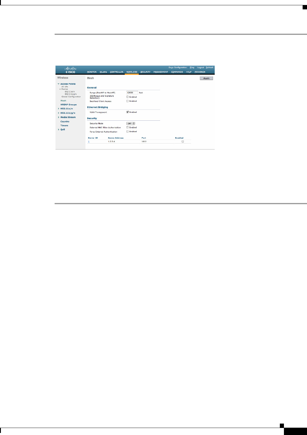
9-35
Cisco Wireless LAN Controller Configuration Guide
OL-21524-02
Chapter 9 Controlling Mesh Access Points
Adding Mesh Access Points to the Mesh Network
Step 1 Choose Wireless > Mesh. The Mesh page appears (see Figure 9-18).
Figure 9-18 Mesh Page
Step 2 In the security section, select the EAP option from the Security Mode drop-down list.
Step 3 Select the Enabled check boxes for the External MAC Filter Authorization and Force External
Authentication options.
Step 4 Click Apply.
Step 5 Click Save Configuration.
Enable External Authentication of Mesh Access Points Using the CLI
To enable external authentication for mesh access points using the CLI, enter the following commands:
1. config mesh security eap
2. config macfilter mac-delimiter colon
3. config mesh security rad-mac-filter enable
4. config mesh radius-server index enable
5. config mesh security force-ext-auth enable (Optional)
View Security Statistics Using the CLI
To view security statistics for mesh access points using the CLI, enter the following command:
show mesh security-stats Cisco_AP
Use this command to display packet error statistics and a count of failures, timeouts, and association and
authentication successes as well as reassociations and reauthentications for the specified access point
and its child.
Configuring Global Mesh Parameters
This section provides instructions to configure the mesh access point to establish a connection with the
controller including:
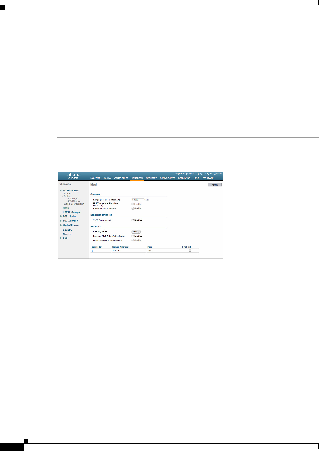
9-36
Cisco Wireless LAN Controller Configuration Guide
OL-21524-02
Chapter 9 Controlling Mesh Access Points
Adding Mesh Access Points to the Mesh Network
• Setting the maximum range between RAP and MAP (not applicable to indoor MAPs).
• Enabling a backhaul to carry client traffic.
• Defining if VLAN tags are forwarded or not.
• Defining the authentication mode (EAP or PSK) and method (local or external) for mesh access
points including security settings (local and external authentication).
You can configure the necessary mesh parameters using either the GUI or the CLI. All parameters are
applied globally.
Configuring Global Mesh Parameters Using the GUI
To configure global mesh parameters using the controller GUI, follow these steps:
Step 1 Choose Wireless > Mesh (see Figure 9-19).
Figure 9-19 Mesh Page
Step 2 Modify the mesh parameters as appropriate. Table 9-6 describes each parameter.

9-37
Cisco Wireless LAN Controller Configuration Guide
OL-21524-02
Chapter 9 Controlling Mesh Access Points
Adding Mesh Access Points to the Mesh Network
.Ta b l e 9-6 Global Mesh Parameters
Parameter Description
Range (RootAP to MeshAP) The optimum distance (in feet) that should exist between
the root access point (RAP) and the mesh access point
(MAP). This global parameter applies to all mesh access
points when they join the controller and all existing mesh
access points in the network.
Range: 150 to 132,000 feet
Default: 12,000 feet
Note After this feature is enabled, all mesh access points
reboot.
IDS (Rogue and Signature
Detection)
When you enable this feature, IDS reports are generated for
all traffic on the client access only and not on the backhaul.
When you disable this feature, no IDS reports are
generated, which preserves bandwidth on the backhaul.
You have to use the following command to enable or
disable it on the mesh APs:
config mesh ids-state {enable | disable}
Note 2.4GHz IDS is activated with the global IDS
settings on the controller.
Backhaul Client Access Note This parameter applies to mesh access points with
two or more radios (1552, 1524SB, 1522, 1240,
1130, and 11n indoor mesh APs) excluding the
1524PS.
When Universal Client Access is enabled, it allows
wireless client association over the backhaul radio.
Generally, backhaul radio is a 5-GHz radio for most of the
mesh access points except for 1522 where backhaul can be
2.4 GHz. This means that a backhaul radio can carry both
backhaul traffic and client traffic.
When Universal Client Access is disabled, only backhaul
traffic is sent over the backhaul radio and client association
is only over the second radio(s).
Default: Disabled
Note After this feature is enabled, all mesh access points
reboot.

9-38
Cisco Wireless LAN Controller Configuration Guide
OL-21524-02
Chapter 9 Controlling Mesh Access Points
Adding Mesh Access Points to the Mesh Network
VLAN Transparent This feature determines how a mesh access point handles
VLAN tags for Ethernet bridged traffic.
Note Refer to the “Configuring Advanced Features”
section on page 9-72 for overview and additional
configuration details.
If VLAN Transparent is enabled, then VLAN tags are not
handled and packets are bridged as untagged packets.
Note No configuration of Ethernet ports is required
when VLAN transparent is enabled. The Ethernet
port passes both tagged and untagged frames
without interpreting the frames.
If VLAN Transparent is disabled, then all packets are
handled according to the VLAN configuration on the port
(trunk, access, or normal mode).
Note If the Ethernet port is set to Trunk mode, then
Ethernet VLAN tagging must be configured. Refer
to “Enabling Ethernet Bridging Using the GUI”
section on page 9-53.
Note For an overview of normal, access, and trunk
Ethernet port use, refer to the “Ethernet Port Notes”
section on page 9-75.
Note To use VLAN tagging, you must uncheck the
VLAN Transparent check box.
Note VLAN Transparent is enabled as a default to ensure
a smooth software upgrade from 4.1.192.xxM
releases to release 5.2. Release 4.1.192.xxM does
not support VLAN tagging (see Figure 9-19).
Default: Enabled.
Security Mode Defines the security mode for mesh access points:
Pre-Shared Key (PSK) or Extensible Authentication
Protocol (EAP).
Note EAP must be selected if external MAC filter
authorization using a RADIUS server is
configured.
Note Local EAP or PSK authentication is performed
within the controller if the External MAC Filter
Authorization parameter is disabled (check box
unchecked).
Options: PSK or EAP
Default: EAP
Table 9-6 Global Mesh Parameters (continued)
Parameter Description

9-39
Cisco Wireless LAN Controller Configuration Guide
OL-21524-02
Chapter 9 Controlling Mesh Access Points
Adding Mesh Access Points to the Mesh Network
External MAC Filter
Authorization
MAC filtering uses the local MAC filter on the controller
by default.
When external MAC filter authorization is enabled, if the
MAC address is not found in the local MAC filter, then the
MAC address in the external RADIUS server is used.
This protects your network against rogue mesh access
points by preventing mesh access points that are not
defined on the external server from joining.
Before employing external authentication within the mesh
network, the following configuration is required:
• The RADIUS server to be used as an AAA server must
be configured on the controller.
• The controller must also be configured on the RADIUS
server.
• The mesh access point configured for external
authorization and authentication must be added to the
user list of the RADIUS server.
–
For remote authorization and authentication,
EAP-FAST uses the manufacturer’s certificate
(CERT) to authenticate the child mesh access
point. Additionally, this manufacturer
certificate-based identity serves as the username
for the mesh access point in user validation.
–
For IOS-based mesh access points (1130, 1240,
1522, 1524), the platform name of the mesh access
point is located in front of its Ethernet address
within the certificate; therefore, their username for
external RADIUS servers is
platform_name_string–Ethernet MAC address
such as c1520-001122334455.
• The certificates must be installed and EAP-FAST must
be configured on the RADIUS server.
Note When this capability is not enabled, by default, the
controller authorizes and authenticates mesh access
points using the MAC address filter.
Default: Disabled.
Force External Authorization When enabled along with EAP and External MAC Filter
Authorization parameters, external authorization and
authentication of mesh access points is done by default by
an external RADIUS server (such as Cisco 4.1 and later).
The RADIUS server overrides local authentication of the
MAC address by the controller which is the default.
Default: Disabled.
Table 9-6 Global Mesh Parameters (continued)
Parameter Description

9-40
Cisco Wireless LAN Controller Configuration Guide
OL-21524-02
Chapter 9 Controlling Mesh Access Points
Adding Mesh Access Points to the Mesh Network
Step 3 Click Apply to commit your changes.
Step 4 Click Save Configuration to save your changes.
Configuring Global Mesh Parameters Using the CLI
To configure global mesh parameters including authentication methods using the controller CLI, follow
these steps.
Note See the “Configuring Global Mesh Parameters Using the GUI” section on page 9-36 for descriptions,
valid ranges, and default values of the parameters used in the CLI commands.
Step 1 To specify the maximum range (in feet) of all mesh access points in the network, enter this command:
config mesh range feet
To see the current range, enter the show mesh range command.
Step 2 To enable or disable IDS reports for all traffic on the backhaul, enter this command:
config mesh ids-state {enable | disable}
Step 3 To specify the rate (in Mbps) at which data is shared between access points on the backhaul interface,
enter this command:
config ap bhrate {rate | auto} Cisco_AP
Step 4 To enable or disable client association on the primary backhaul (802.11a) of a mesh access point, enter
these commands:
config mesh client-access {enable | disable}
config ap wlan {enable | disable} 802.11a Cisco_AP
config ap wlan {add | delete} 802.11a wlan_id Cisco_AP
Step 5 To enable or disable VLAN transparent, enter this command:
config mesh ethernet-bridging VLAN-transparent {enable | disable}
Step 6 To define a security mode for the mesh access point, enter one of the following commands:
a. To provide local authentication of the mesh access point by the controller, enter this command:
config mesh security {eap | psk}
b. To store the MAC address filter in an external RADIUS server for authentication instead of the
controller (local), enter these commands:
config macfilter mac-delimiter colon
config mesh security rad-mac-filter enable
config mesh radius-server index enable
c. To provide external authentication on a RADIUS server and define a local MAC filter on the
controller, enter these commands:
config mesh security eap
config macfilter mac-delimiter colon
config mesh security rad-mac-filter enable

9-41
Cisco Wireless LAN Controller Configuration Guide
OL-21524-02
Chapter 9 Controlling Mesh Access Points
Adding Mesh Access Points to the Mesh Network
config mesh radius-server index enable
config mesh security force-ext-auth enable
d. To provide external authentication on a RADIUS server using a MAC username (such as
c1520-123456) on the RADIUS server, enter these commands:
config macfilter mac-delimiter colon
config mesh security rad-mac-filter enable
config mesh radius-server index enable
config mesh security force-ext-auth enable
Step 7 To save your changes, enter this command:
save config
Viewing Global Mesh Parameter Settings Using the CLI
Use these commands to obtain information on global mesh settings:
• show mesh client-access—When Universal Client Access is enabled, it allows wireless client
association over the backhaul radio. Generally, backhaul radio is a 5-GHz radio for most of the mesh
access points except for 1522 where backhaul can be 2.4 GHz. This means that a backhaul radio can
carry both backhaul traffic and client traffic.
When Universal Client Access is disabled, only backhaul traffic is sent over the backhaul radio and
client association is only over the second radio(s).
controller >show mesh client-access
Backhaul with client access status: enabled
• show mesh ids-state—Shows the status of the IDS reports on the backhaul as either enabled or
disabled.
controller >show mesh ids-state
Outdoor Mesh IDS(Rogue/Signature Detect): .... Disabled
• show mesh config—Displays global configuration settings.
(Cisco Controller) > show mesh config
Mesh Range....................................... 12000
Mesh Statistics update period.................... 3 minutes
Backhaul with client access status............... disabled
Background Scanning State........................ enabled
Backhaul Amsdu State............................. disabled
Mesh Security
Security Mode................................. EAP
External-Auth................................. disabled
Use MAC Filter in External AAA server......... disabled
Force External Authentication................. disabled
Mesh Alarm Criteria
Max Hop Count................................. 4
Recommended Max Children for MAP.............. 10
Recommended Max Children for RAP.............. 20
Low Link SNR.................................. 12
High Link SNR................................. 60
Max Association Number........................ 10
Association Interval.......................... 60 minutes

9-42
Cisco Wireless LAN Controller Configuration Guide
OL-21524-02
Chapter 9 Controlling Mesh Access Points
Adding Mesh Access Points to the Mesh Network
Parent Change Numbers......................... 3
Parent Change Interval........................ 60 minutes
Mesh Multicast Mode.............................. In-Out
Mesh Full Sector DFS............................. enabled
Mesh Ethernet Bridging VLAN Transparent Mode..... enabled
Universal Client Access
When Universal Client Access is enabled, it allows wireless client association over the backhaul radio.
Generally, backhaul radio is a 5-GHz radio for most of the mesh access points except for 1522 where
backhaul can be 2.4 GHz. This means that a backhaul radio can carry both backhaul traffic and client
traffic.
When Universal Client Access is disabled, only backhaul traffic is sent over the backhaul radio and client
association is only over the second radio(s).
Note Universal Client Access is disabled by default.
After this feature is enabled, all mesh access points reboot.
This feature is applicable to mesh access points with two or more radios (1552, 1524SB, 1522, Indoor
APs in mesh mode) excluding the 1524PS.
Configuring Universal Client Access using the GUI
Figure 9-20 shows how to enable Universal Client Access using the GUI. You will be prompted that the
AP will reboot if you enable Universal Client Access.
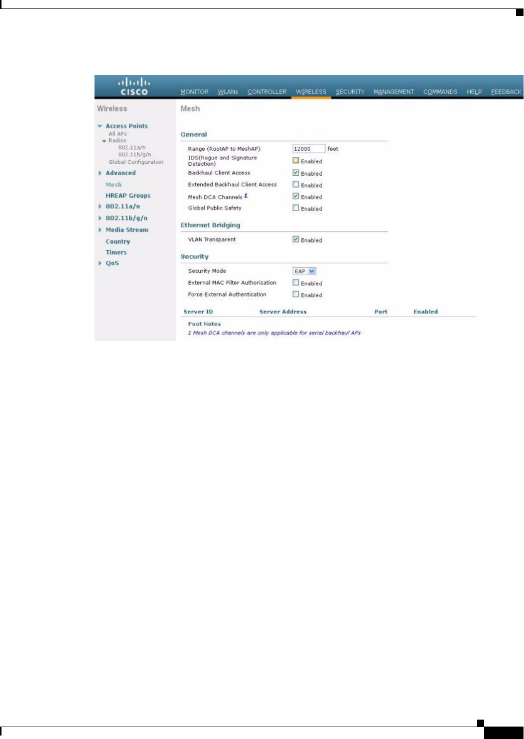
9-43
Cisco Wireless LAN Controller Configuration Guide
OL-21524-02
Chapter 9 Controlling Mesh Access Points
Adding Mesh Access Points to the Mesh Network
Figure 9-20 Configuring Universal Client Access using the GUI
Configuring Universal Client Access using the CLI
Use the following command to enable Universal Client Access:
(Cisco Controller)> config mesh client-access enable
The following message is displayed:
All Mesh APs will be rebooted
Are you sure you want to start? (y/N)
Universal Client Access on Serial Backhaul Access Points
With universal client access, you can have client access on the backhaul 802.11a radios in addition to
the backhaul functionality. This feature is applicable to mesh access points with two or more radios
(1552, 1524SB, 1522, Indoor APs in mesh mode) excluding the 1524PS.
The dual 5-GHz Universal Client Access feature is intended for the serial backhaul access point
platform, which has three radio slots. The radio in slot 0 operates in the 2.4-GHz band and is used for
client access. The radios in slot 1 and slot 2 operate in the 5-GHz band and are primarily used for
backhaul. However, with the Universal Client Access feature, clients were allowed to associate over the
slot 1 radio. But slot 2 radio was used only for backhaul. With the 7.0 release, client access over the slot
2 radio is allowed with this Dual 5-GHz Universal Access feature.
By default, client access is disabled over both the backhaul radios. Follow the guidelines to enable or
disable client access on the radio slots that constitute 5-GHz radios, irrespective of the radios being used
as downlinks or uplinks:
• You can enable client access on slot 1 even if client access on slot 2 is disabled.
• You can enable client access on slot 2 only when client access on slot 1 is enabled.
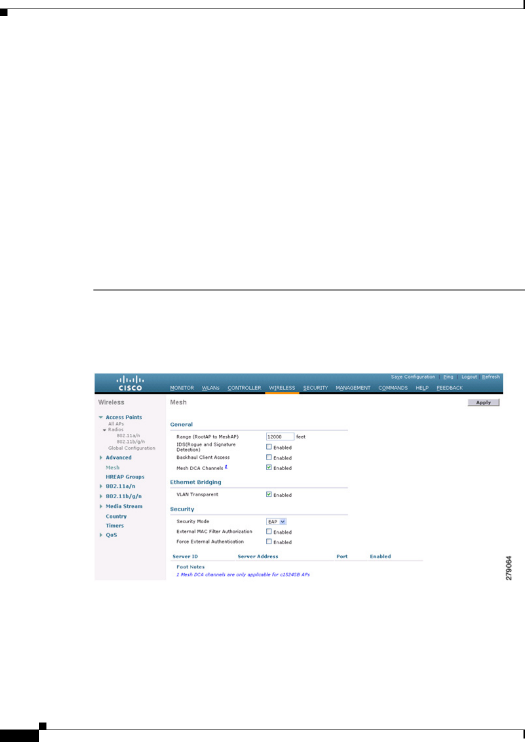
9-44
Cisco Wireless LAN Controller Configuration Guide
OL-21524-02
Chapter 9 Controlling Mesh Access Points
Adding Mesh Access Points to the Mesh Network
• If you disable client access on slot 1, client access on slot 2 is automatically disabled on the CLI.
• To disable only the extended client access (on the slot 2 radio), use the GUI.
• All the mesh access points reboot whenever client access is enabled or disabled.
The two 802.11a backhaul radios use the same MAC address. There may be instances where a WLAN
maps to the same BSSID on more than one slot. Client access on the slot 2 radio is referred to as
Extended Universal Access (EUA) in this document.
You can configure Extended Universal Access using one of the following methods:
• “Configuring Extended Universal Access Using the GUI” section on page 9-44
• “Configuring Extended Universal Access Using the CLI” section on page 9-46
• “Configuring Extended Universal Access from the Wireless Control System (WCS)” section on
page 9-47
Configuring Extended Universal Access Using the GUI
To configure the Extended Universal Access, follow these steps:
Step 1 Choose Controller > Wireless > Mesh.
The Controller GUI when Backhaul Client Access is disabled page appears as shown in Figure 9-21.
Figure 9-21 Advanced Controller Settings for Mesh Page
Step 2 Select the Backhaul Client Access check box to display the Extended Backhaul Client Access check
box.
Step 3 Select the Extended Backhaul Client Access check box and click Apply. A message appears as shown
in Figure 9-22.
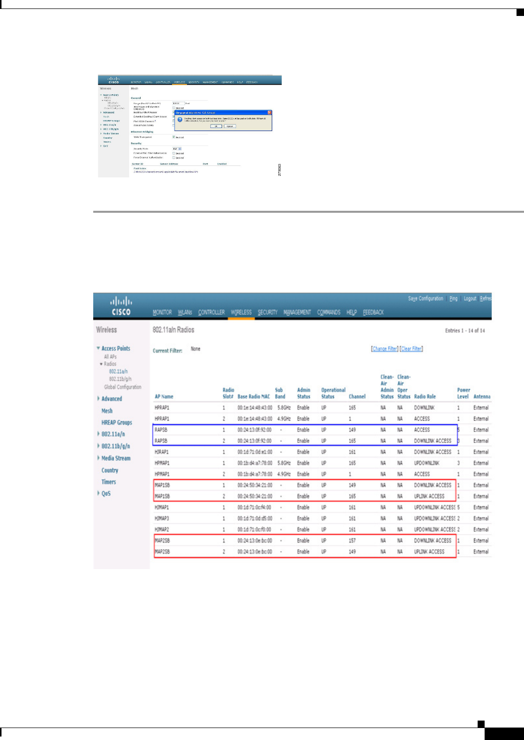
9-45
Cisco Wireless LAN Controller Configuration Guide
OL-21524-02
Chapter 9 Controlling Mesh Access Points
Adding Mesh Access Points to the Mesh Network
Figure 9-22 Advanced Controller Settings for Mesh Page
Step 4 Click OK.
After EUA is enabled, 802.11a radios are displayed as shown in Figure 9-23.
Figure 9-23 802.11a Radios after EUA is Enabled
Slot 2 in the 5-GHz radio in the RAPSB (serial backhaul) that is used to extend the backhaul in the
DOWNLINK direction is displayed as DOWNLINK ACCESS, where slot 1 in the 5-GHz radio in the
RAPSB that is used for client access is displayed as ACCESS. Slot 2 in the 5-GHz radio in the MAPSB
that is used for the UPLINK is displayed as UPLINK ACCESS, and slot 1 in the MAPSB is used for the
DOWNLINK ACCESS with an omnidirectional antenna that also provides the client access.
Create WLAN on the WLC with the appropriate SSID mapped to the correct interface (VLAN). After
you create a WLAN, it is applied to all the radios by default. If you want to enable client access only on
802.11a radios, then choose only the appropriate radio policy from the list shown in Figure 9-24.
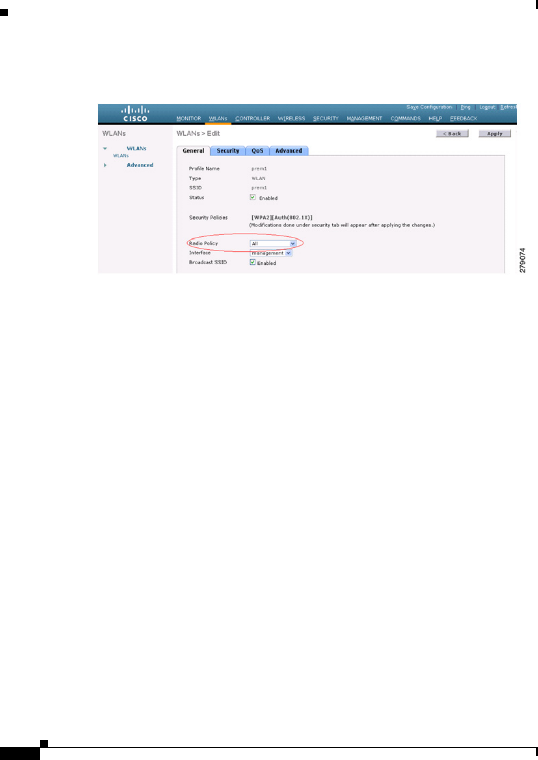
9-46
Cisco Wireless LAN Controller Configuration Guide
OL-21524-02
Chapter 9 Controlling Mesh Access Points
Adding Mesh Access Points to the Mesh Network
Figure 9-24 Radio Policy Selection
Configuring Extended Universal Access Using the CLI
• Go to the Controller prompt and enter the config mesh client-access enable extended command.
The following message is displayed:
Enabling client access on both backhaul slots
Same BSSIDs will be used on both slots
All Mesh Serial Backhaul APs will be rebooted
Are you sure you want to start? (y/N)
• Enter the show mesh client-access command to know the status of the backhaul with client access
and the backhaul with client access extended.
The status is displayed as follows:
Backhaul with client access status: enabled
Backhaul with client access extended status(3 radio AP): enabled
• There is no explicit command to disable client access only on slot 2 (EUA). You have to disable
client access on both the backhaul slots by entering the following command:
config mesh client-access disable
The following message is displayed:
All Mesh APs will be rebooted
Are you sure you want to start? (y/N)
• You can disable EUA from the GUI without disturbing client access on the slot 1 radio, but all
1524SB access points will be rebooted.
It is possible to enable client access only on slot 1 and not on slot 2 by entering the following
command:
config mesh client-access enable
The following message is displayed:
All Mesh APs will be rebooted
Are you sure you want to start? (y/N)
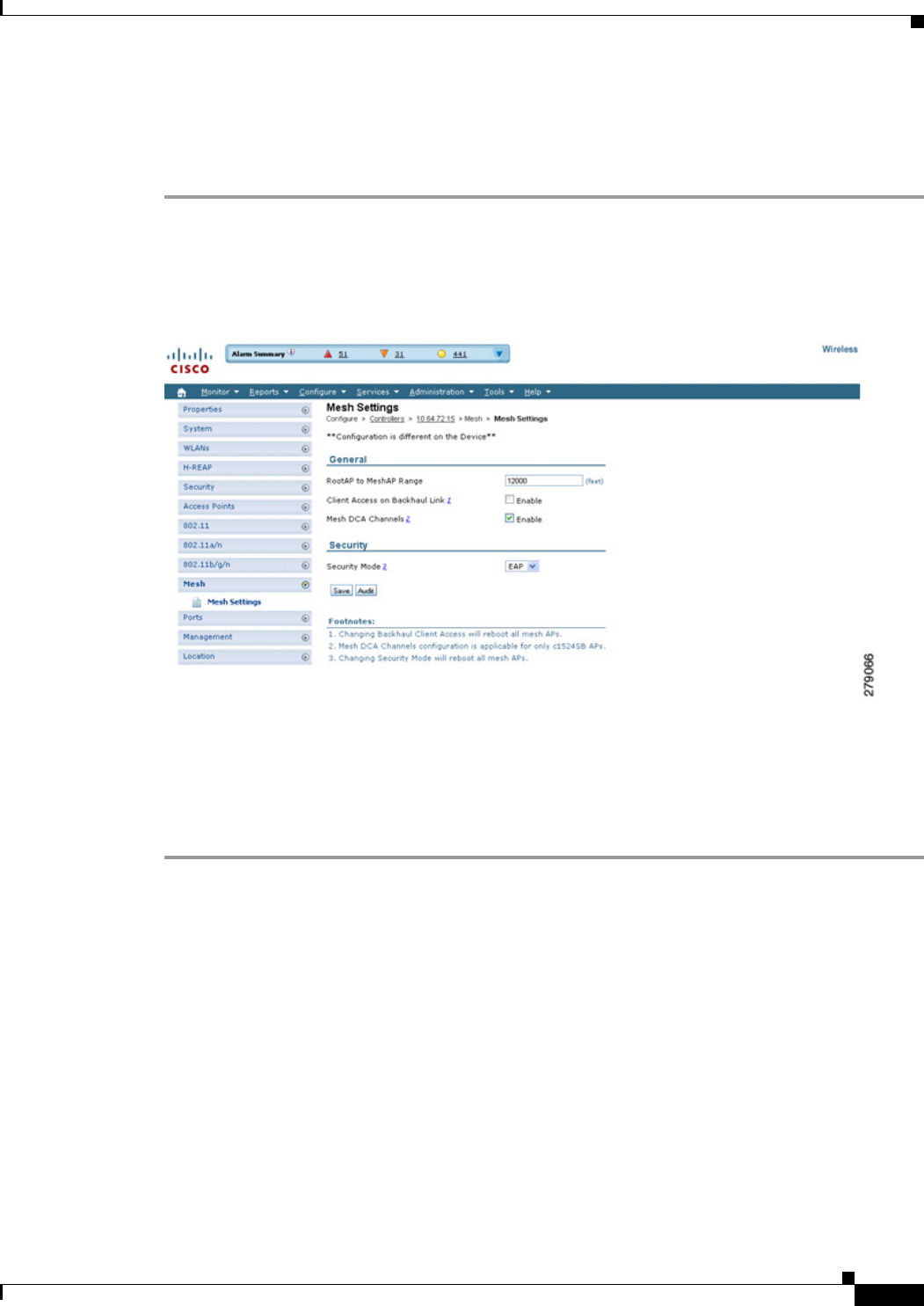
9-47
Cisco Wireless LAN Controller Configuration Guide
OL-21524-02
Chapter 9 Controlling Mesh Access Points
Adding Mesh Access Points to the Mesh Network
Configuring Extended Universal Access from the Wireless Control System (WCS)
Step 1 Choose Controllers > Controller IP Address > Mesh > Mesh Settings.
The WCS Mesh page when Backhaul Client Access is disabled appears as shown in Figure 9-25.
Figure 9-25 Mesh Settings Page
Step 2 Select the Client Access on Backhaul Link check box to display the Extended Backhaul Client Access
check box.
Step 3 Select the Extended Backhaul Client Access check box and click Apply. A message appears indicating
the possible results of enabling the Extended Backhaul Client Access.
Step 4 Click OK to continue.
Configuring Local Mesh Parameters
After configuring global mesh parameters, you must configure the following local mesh parameters for
these specific features if in use in your network:
• Backhaul Data Rate. See the “Configuring Wireless Backhaul Data Rate” section on page 9-48.
• Ethernet Bridging. See the “Configuring Ethernet Bridging” section on page 9-52.
• Bridge Group Name. See the“Configuring Ethernet Bridging” section on page 9-52.
• Workgroup Bridge. See the “Configuring Workgroup Bridges” section on page 9-84.
• Public Safety Band Settings. See the “Configuring Public Safety Band Settings” section on
page 9-56.

9-48
Cisco Wireless LAN Controller Configuration Guide
OL-21524-02
Chapter 9 Controlling Mesh Access Points
Adding Mesh Access Points to the Mesh Network
• Cisco 3200 Series Association and Interoperability. See the “Table 9-10 identifies mesh access
points and their respective frequency bands that support WGB.” section on page 9-93.
• Power and Channel Setting. See the“Configuring Power and Channel Settings” section on
page 9-60.
• Antenna Gain Settings. See the “Configuring Antenna Gain” section on page 9-63.
• Dynamic Channel Assignment. See the “Configuring Dynamic Channel Assignment” section on
page 9-69.
Configuring Wireless Backhaul Data Rate
Backhaul is used to create only the wireless connection between the access points. The backhaul
interface by default is 802.11a or 802.11a/n depending upon the access point. The rate selection is
important for effective use of the available RF spectrum. The rate can also affect the throughput of client
devices, and throughput is an important metric used by industry publications to evaluate vendor devices.
Dynamic Rate Adaptation (DRA) introduces a process to estimate optimal transmission rate for packet
transmissions. It is important to select rates correctly. If the rate is too high, packet transmissions fail
resulting in communication failure. If the rate is too low, the available channel bandwidth is not used,
resulting in inferior products, and the potential for catastrophic network congestion and collapse.
Data rates also affect the RF coverage and network performance. Lower data rates, for example 6 Mbps,
can extend farther from the access point than can higher data rates, for example 300 Mbps. As a result,
the data rate affects cell coverage and consequently the number of access points required. Different data
rates are achieved by sending a more redundant signal on the wireless link, allowing data to be easily
recovered from noise. The number of symbols sent out for a packet at the 1-Mbps data rate is higher than
the number of symbols used for the same packet at 11 Mbps. Therefore, sending data at the lower bit
rates takes more time than sending the equivalent data at a higher bit rate, resulting in reduced
throughput.
In the controller release 5.2, the default data rate for the mesh 5-GHz backhaul is 24 Mbps. It remains
the same with 6.0 and 7.0 controller releases.
With the 6.0 controller release, mesh backhaul can be configured for ‘Auto’ data rate. Once configured,
the access point picks the highest rate where the next higher rate cannot be used because of conditions
not being suitable for that rate and not because of conditions that affect all rates. That is, once
configured, each link is free to settle down to the best possible rate for its link quality.
We recommend that you configure the mesh backhaul to Auto.
For example, if mesh backhaul chose 48 Mbps, then this decision is taken after ensuring that we cannot
use 54 Mbps as there is not enough SNR for 54 and not because some just turned the microwave oven
on which affects all rates.
A lower bit rate might allow a greater distance between MAPs, but there are likely to be gaps in the
WLAN client coverage, and the capacity of the backhaul network is reduced. An increased bit rate for
the backhaul network either requires more MAPs or results in a reduced SNR between MAPs, limiting
mesh reliability and interconnection.
Figure 9-26 shows the RAP using the "auto" backhaul data rate, and it is currently using 54 Mbps with
its child MAP.
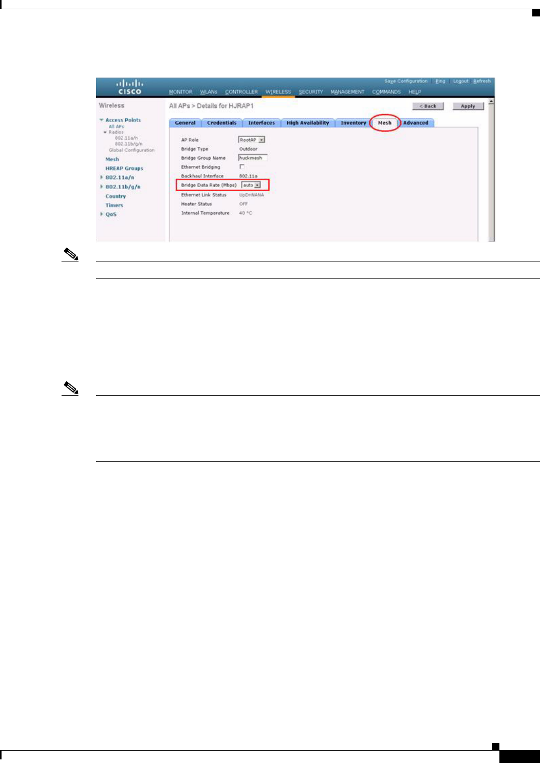
9-49
Cisco Wireless LAN Controller Configuration Guide
OL-21524-02
Chapter 9 Controlling Mesh Access Points
Adding Mesh Access Points to the Mesh Network
Figure 9-26 Bridge Rate Set to Auto
Note The data rate can be set on the backhaul on a per-AP basis. It is not a global command.
Related Commands
Use these commands to obtain information about backhaul:
• config ap bhrate—Configures the Cisco Bridge backhaul Tx rate.
The syntax is as follows:
(controller) > config ap bhrate backhaul-rate ap-name
Note Preconfigured data rates for each AP (RAP=18 Mbps, MAP1=36 Mbps) are preserved after the upgrade
to 6.0 or later software releases.
Before you upgrade to the 6.0 release, if you have the backhaul data rate configured to any data rate, then
the configuration is preserved.
The following example shows how to configure a backhaul rate of 36000 Kbps on a RAP:
(controller) > config ap bhrate 36000 HPRAP1
• show ap bhrate—Displays the Cisco Bridge backhaul rate.
The syntax is as follows:
(controller) > show ap bhrate ap-name
• show mesh neigh summary—Displays the link rate summary including the current rate being used
in backhaul
Example:
(controller) > show mesh neigh summary HPRAP1
AP Name/Radio Channel Rate Link-Snr Flags State
--------------- -------- -------- ------- ----- -----
00:0B:85:5C:B9:20 0 auto 4 0x10e8fcb8 BEACON
00:0B:85:5F:FF:60 0 auto 4 0x10e8fcb8 BEACON DEFAULT
00:0B:85:62:1E:00 165 auto 4 0x10e8fcb8 BEACON
OO:0B:85:70:8C:A0 0 auto 1 0x10e8fcb8 BEACON
HPMAP1 165 54 40 0x36 CHILD BEACON

9-50
Cisco Wireless LAN Controller Configuration Guide
OL-21524-02
Chapter 9 Controlling Mesh Access Points
Adding Mesh Access Points to the Mesh Network
HJMAP2 0 auto 4 0x10e8fcb8 BEACON
Backhaul capacity and throughput depends upon the type of the AP, that is, if it is 802.11a/n or only
802.11a, number of backhaul radios it has, and so on.
In AP1524 SB, Slot 2 in the 5-GHz radio in the RAP is used to extend the backhaul in the downlink
direction, whereas Slot 2 in the 5-GHz radio in the MAP is used for backhaul in the uplink. We
recommend using a directional antenna with the Slot 2 radio. MAPs extend Slot 1 radio in the downlink
direction with Omni or directional antenna also providing client access. Client access can be provided
on the Slot 2 radio from the 7.0 release onwards.
AP1524SB provides you with better throughput, and throughput rarely degrades after the first hop. The
performance of AP1524SB is better than AP1522 and AP1524PS because these APs have only a single
radio for the backhaul uplink and downlink (see Figure 9-27, Figure 9-28, Figure 9-29, and
Figure 9-30).
Figure 9-27 1524SB TCP Downstream Rate Auto
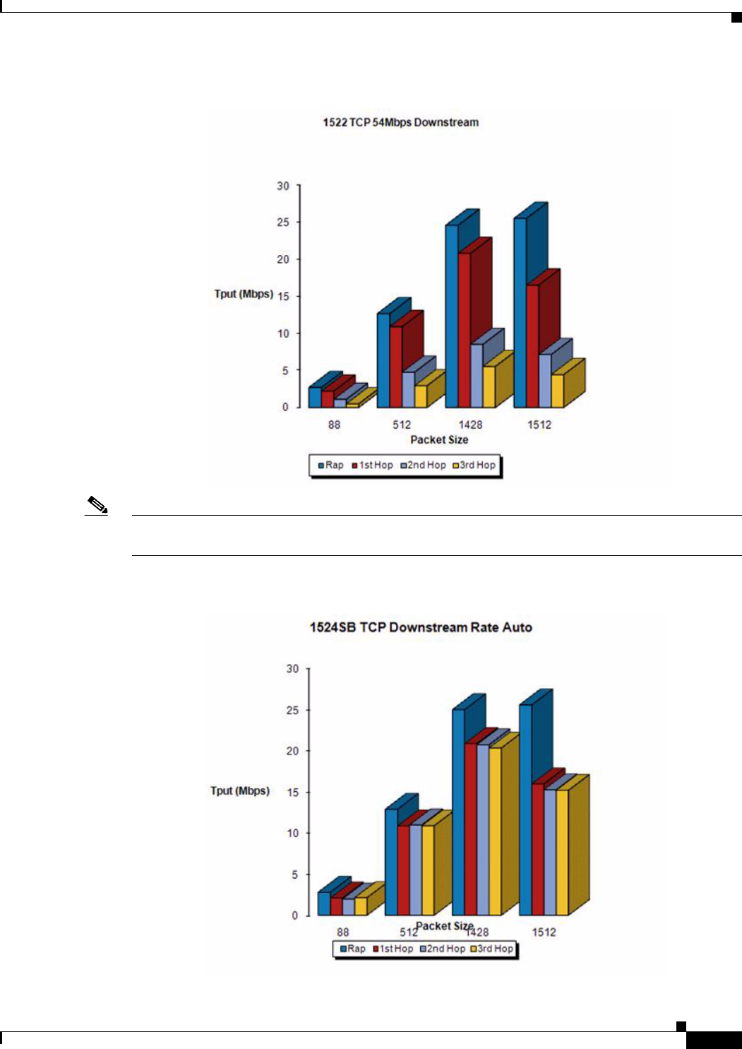
9-51
Cisco Wireless LAN Controller Configuration Guide
OL-21524-02
Chapter 9 Controlling Mesh Access Points
Adding Mesh Access Points to the Mesh Network
Figure 9-28 1522 TCP 54 Mbps Downstream
Note With DRA, each hop uses the best possible data rate for the backhaul. The data rate can be changed on
a per-AP basis.
Figure 9-29 1524SB TCP Downstream Rate Auto
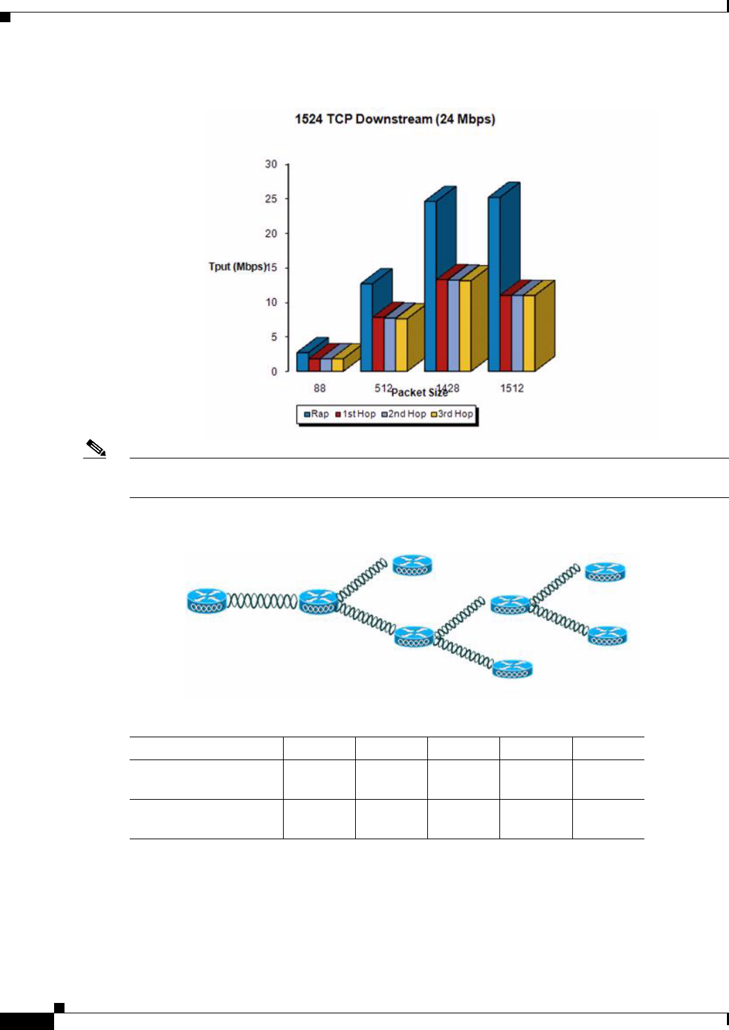
9-52
Cisco Wireless LAN Controller Configuration Guide
OL-21524-02
Chapter 9 Controlling Mesh Access Points
Adding Mesh Access Points to the Mesh Network
Figure 9-30 1524 TCP Downstream (24 Mbps)
Note Using 1552 802.11n provides you higher throughput and more capacity. It offers a very fat backhaul pipe
to start with from the RAP.
Figure 9-31 AP1552 Backhaul Throughput
Configuring Ethernet Bridging
For security reasons, the Ethernet port on all MAPs is disabled by default. It can be enabled only by
configuring Ethernet bridging on the root and its respective MAP.
Ta b l e 9-7 AP1552 Backhaul capacity
HOPS RAP One Two Three Four
Maximum Throughput
(20 MHz BH)
112 Mbps 83 Mbps 41 Mbps 25 Mbps 15 Mbps
Maximum Throughput
(40 MHz BH)
206 Mbps 111 Mbps 94 Mbps 49 Mbps 35 Mbps
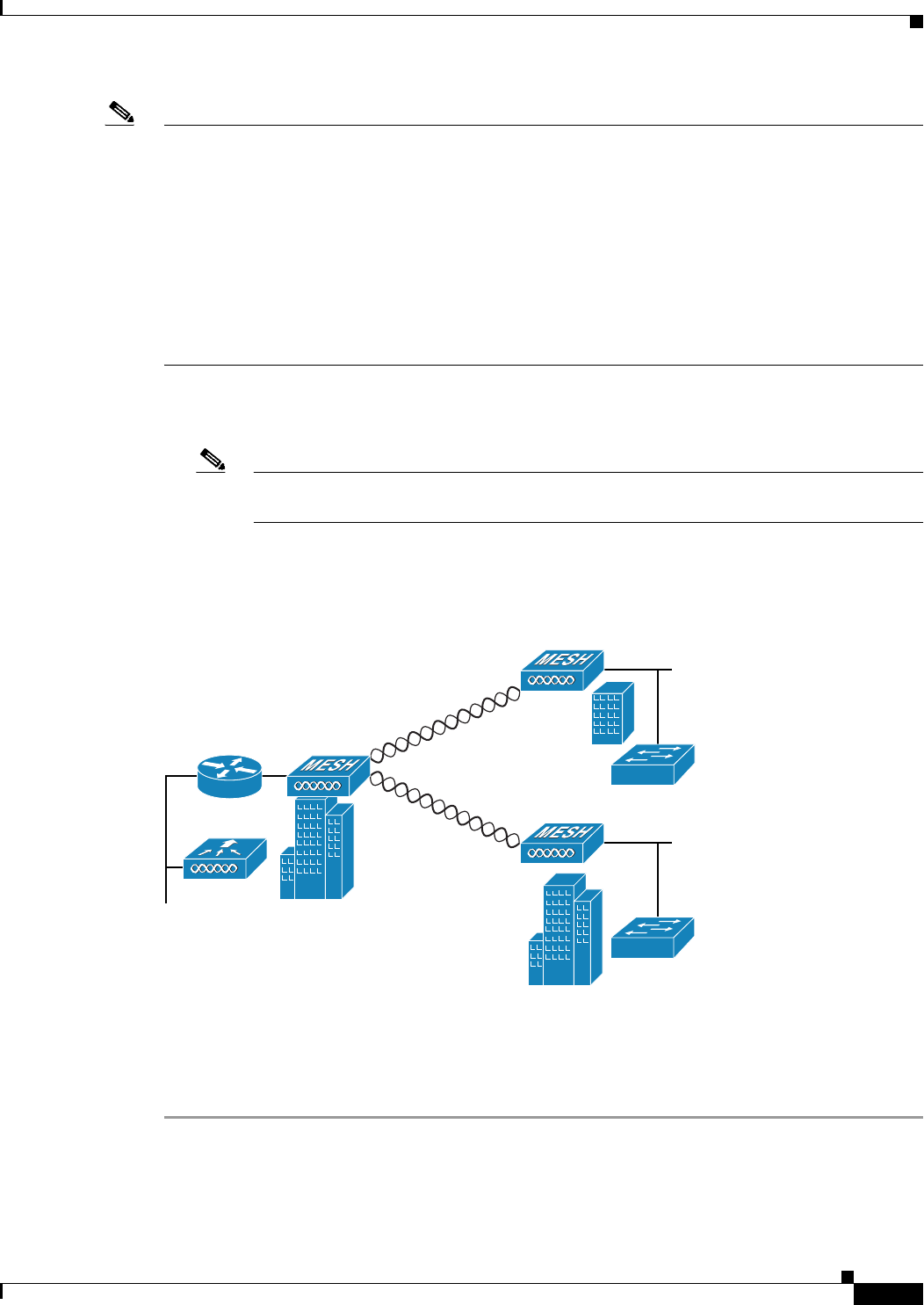
9-53
Cisco Wireless LAN Controller Configuration Guide
OL-21524-02
Chapter 9 Controlling Mesh Access Points
Adding Mesh Access Points to the Mesh Network
Note Exceptions are allowed for a few protocols even though Ethernet bridging is disabled. For example, the
following protocols are allowed:
– Spanning Tree Protocol (STP)
– Address Resolution Protocol (ARP)
– Control And Provisioning of Wireless Access Points (CAPWAP)
– Bootstrap Protocol (BOOTP) packets
Due to the exceptions and to prevent loop issues, we recommend that you do not connect two MAPs to
each other over their Ethernet ports, unless they are configured as trunk ports on different native VLANs,
and each is connected to a similarly configured switch.
Ethernet bridging has to be enabled for two scenarios:
1. When you want to use the mesh nodes as bridges. (See Figure 9-32.)
Note You do not need to configure VLAN tagging to use Ethernet bridging for point-to-point and
point-to-multipoint bridging deployments.
2. When you want to connect any Ethernet device such as a video camera on the MAP using its
Ethernet port. This is the first step to enable VLAN tagging.
Figure 9-32 Point-to-Multipoint Bridging
Enabling Ethernet Bridging Using the GUI
To enable Ethernet bridging on a RAP or MAP using the GUI, follow these steps:
Step 1 Choose Wireless > All APs.
Step 2 Click the AP name link of the mesh access point on which you want to enable Ethernet bridging.
Step 3 At the details page, select the Mesh tab. (See Figure 9-33.)
148439
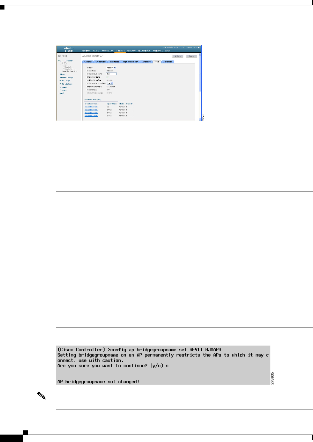
9-54
Cisco Wireless LAN Controller Configuration Guide
OL-21524-02
Chapter 9 Controlling Mesh Access Points
Adding Mesh Access Points to the Mesh Network
Figure 9-33 All APs > Details for (Mesh) Page
Step 4 Select either RootAP or MeshAP from the AP Role drop-down list, if not already selected.
Step 5 Select the Ethernet Bridging check box to enable Ethernet bridging or deselect it to disable this feature.
Step 6 Click Apply to commit your changes. An Ethernet Bridging section appears at the bottom of the page
listing each of the Ethernet ports of the mesh access point.
Step 7 Ensure that you enable Ethernet bridging for every parent mesh AP taking the path from the mesh AP in
question to the controller. For example, if you enable Ethernet bridging on MAP2 in Hop 2, then you
must also enable Ethernet bridging on MAP1 (parent MAP), and on the RAP connecting to the controller.
Configuring Bridge Group Names
Bridge group names (BGNs) control the association of mesh access points. BGNs can logically group
radios to avoid two networks on the same channel from communicating with each other. The setting is
also useful if you have more than one RAP in your network in the same sector (area). BGN is a string of
10 characters maximum.
A BGN of NULL VALUE is assigned by default by manufacturing. Although not visible to you, it allows
a mesh access point to join the network prior to your assignment of your network-specific BGN.
If you have two RAPs in your network in the same sector (for more capacity), we recommend that you
configure the two RAPs with the same BGN, but on different channels.
Configuring BGN Using the CLI
To configure a BGN, follow these steps:
Step 1 Using the CLI, enter the following command:
Note The mesh access point reboots after a BGN configuration.