Cisco Systems 102075 Cisco Aironet 802.11n Dual Band Access Points User Manual Cisco Wireless LAN Controller Configuration Guide 4
Cisco Systems Inc Cisco Aironet 802.11n Dual Band Access Points Cisco Wireless LAN Controller Configuration Guide 4
Contents
- 1. User manual
- 2. Cisco Wireless LAN Controller Configuration Guide_1
- 3. Cisco Wireless LAN Controller Configuration Guide_2
- 4. Cisco Wireless LAN Controller Configuration Guide_3
- 5. Cisco Wireless LAN Controller Configuration Guide_4
- 6. Cisco Wireless LAN Controller Configuration Guide_5
- 7. Cisco Wireless LAN Controller Configuration Guide_6
- 8. Cisco Wireless LAN Controller Configuration Guide_7
- 9. Cisco Wireless LAN Controller Configuration Guide_8
- 10. Cisco Wireless LAN Controller Configuration Guide_9
- 11. Cisco Wireless LAN Controller Configuration Guide_10
- 12. Cisco Wireless LAN Controller Configuration Guide_11
- 13. User Manual
Cisco Wireless LAN Controller Configuration Guide_4

CHAPTER
7-1
Cisco Wireless LAN Controller Configuration Guide
OL-21524-02
7
Configuring WLANs
This chapter describes how to configure up to 512 WLANs for your Cisco UWN solution. It contains
these sections:
• WLAN Overview, page 7-1
• Configuring WLANs, page 7-2
WLAN Overview
The Cisco UWN solution can control up to 512 WLANs for lightweight access points. Each WLAN has
a separate WLAN ID (1 through 512), a separate profile name, and a WLAN SSID. All controllers
publish up to 16 WLANs to each connected access point, but you can create up to 512 WLANs and then
selectively publish these WLANs (using access point groups) to different access points to better manage
your wireless network.
Note Cisco 2106, 2112, and 2125 Controllers support only up to 16 WLANs.
Note All OfficeExtend access points should be in the same access point group, and that group should contain
no more than 15 WLANs. A controller with OfficeExtend access points in an access point group
publishes only up to 15 WLANs to each connected OfficeExtend access point because it reserves one
WLAN for the personal SSID.
You can associate up to 16 WLANs with each access point group and assign specific access points to
each group. Each access point advertises only the enabled WLANs that belong to its access point group.
The access point does not advertise disabled WLANs in its access point group or WLANs that belong to
another group. See the “Creating Access Point Groups” section on page 7-57 for more information on
access point groups.
Note Controller software releases prior to 5.2 support up to only 16 WLANs. Cisco does not support
downgrading the controller from software release 5.2 or later releases to a previous release because
inconsistencies might occur for WLANs and wired guest LANs. As a result, you would need to
reconfigure your WLAN, mobility anchor, and wired LAN configurations.

7-2
Cisco Wireless LAN Controller Configuration Guide
OL-21524-02
Chapter 7 Configuring WLANs
Configuring WLANs
Note We recommend that you assign one set of VLANs for WLANs and a different set of VLANs for
management interfaces to ensure that controllers properly route VLAN traffic.
Configuring WLANs
These sections describe how to configure WLANs:
• Creating WLANs, page 7-2
• Using the GUI to Search WLANs, page 7-7
• Configuring DHCP, page 7-10
• Configuring MAC Filtering for WLANs, page 7-17
• Assigning WLANs to Interfaces, page 7-18
• Configuring the DTIM Period, page 7-19
• Configuring Peer-to-Peer Blocking, page 7-21
• Configuring Layer 2 Security, page 7-24
• Configuring a Session Timeout, page 7-31
• Configuring Layer 3 Security, page 7-32
• Assigning a QoS Profile to a WLAN, page 7-37
• Configuring QoS Enhanced BSS, page 7-39
• Configuring Media Session Snooping and Reporting, page 7-42
• Configuring IPv6 Bridging, page 7-49
• Configuring Cisco Client Extensions, page 7-52
• Configuring Access Point Groups, page 7-55
• Configuring Web Redirect with 802.1X Authentication, page 7-62
• Using the GUI to Disable the Accounting Servers per WLAN, page 7-66
• Disabling Coverage Hole Detection per WLAN, page 7-67
• Configuring NAC Out-of-Band Integration, page 7-68
• Configuring Passive Client, page 7-74
Creating WLANs
This section describes how to create up to 512 WLANs using either the controller GUI or CLI.
You can configure WLANs with different Service Set Identifiers (SSIDs) or with the same SSID. An
SSID identifies the specific wireless network that you want the controller to access.
The controller uses different attributes to differentiate between WLANs with the same SSID.
• WLANS with the same SSID and same L2 Policy cannot be created if the WLAN ID < 17.
• Two WLANs with ids greater than 17 having the same SSID and same L2 policy is allowed provided
WLANS are added in different AP groups.

7-3
Cisco Wireless LAN Controller Configuration Guide
OL-21524-02
Chapter 7 Configuring WLANs
Configuring WLANs
Note This requirement ensures that clients never detect the SSID present on the same access point
radio.
When creating a WLAN with the same SSID, follow these guidelines and requirements:
• You must create a unique profile name for each WLAN.
• When multiple WLANs with the same SSID get assigned to the same AP radio, you must have a
unique Layer 2 security policy so that clients can safely select between them.
WLANs with the same SSID must have unique Layer 2 security policies so that clients can make a
WLAN selection based on information advertised in beacon and probe responses. The available Layer 2
security policies are as follows:
• None (open WLAN)
• Static WEP or 802.1X
Note Because static WEP and 802.1X are both advertised by the same bit in beacon and probe
responses, they cannot be differentiated by clients. Therefore, they cannot both be used by
multiple WLANs with the same SSID.
• CKIP
• WPA/WPA2
Note Although WPA and WPA2 cannot be used by multiple WLANs with the same SSID, you can
configure two WLANs with the same SSID with WPA/TKIP with PSK and WPA (Wi-Fi
Protected Access) /TKIP (Temporal Key Integrity Protocol) with 802.1X, respectively, or
with WPA/TKIP with 802.1X or WPA/AES with 802.1X, respectively.
Caution Some clients might not be able to connect to WLANs properly if they detect the same SSID with multiple
security policies. Use this feature with care.
Note The OEAP 600 Series access point supports a maximum of two WLANs and one remote LAN. If you
have configured more than two WLANs and one remote LAN, you can assign the 600 Series access point
to an AP group. The support for two WLANs and one remote LAN still applies to the AP Group If the
600 Series OEAP is in the default group, the WLAN or remote LAN IDs must be lower than 8.
Cisco Flex 7500 Series Controller does not support the 802.1x security variants on a centrally switched
WLAN. For example, the following configurations are not allowed on a centrally switched WLAN:
• WPA1/WPA2 with 802.1x AKM
• WPA1/WPA2 with CCKM
• Dynamic-WEP
• Conditional webauth
• Splash WEB page redirect
7-4
Cisco Wireless LAN Controller Configuration Guide
OL-21524-02
Chapter 7 Configuring WLANs
Configuring WLANs
If you want to configure your WLAN in any of the above combinations, the WLAN must be configured
to use local switching.
Using the GUI to Create WLANs
To create WLANs using the controller GUI, follow these steps:
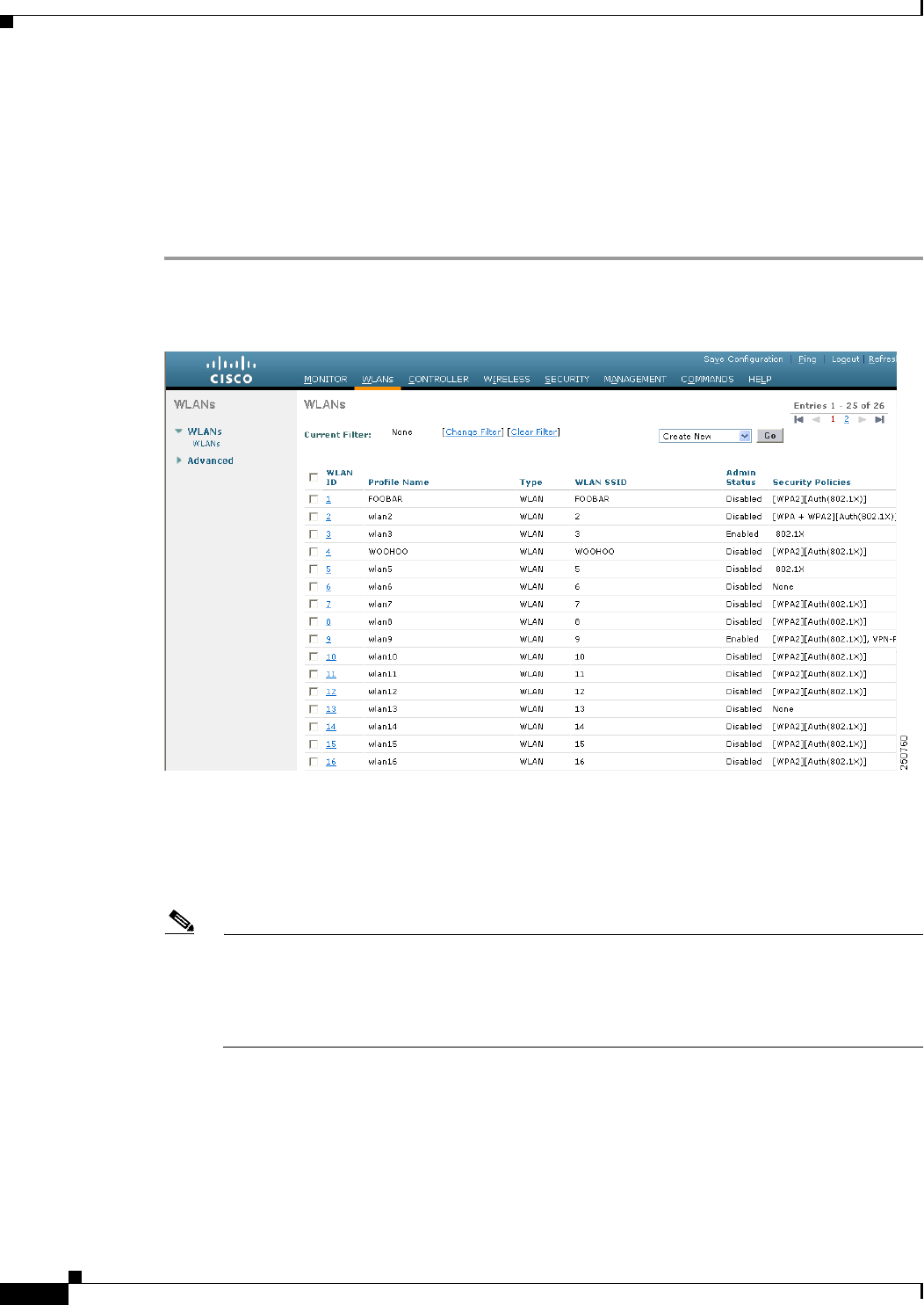
Step 1 Choose WLANs to open the WLANs page (see Figure 7-1).
Figure 7-1 WLANs Page
This page lists all of the WLANs currently configured on the controller. For each WLAN, you can see
its WLAN ID, profile name, type, SSID, status, and security policies.
The total number of WLANs appears in the upper right-hand corner of the page. If the list of WLANs
spans multiple pages, you can access these pages by clicking the page number links.
Note If you want to delete a WLAN, hover your cursor over the blue drop-down arrow for that WLAN
and choose Remove, or select the check box to the left of the WLAN, choose Remove Selected
from the drop-down list, and click Go. A message appears asking you to confirm your decision.
If you proceed, the WLAN is removed from any access point group to which it is assigned and
from the access point’s radio.
Step 2 Create a new WLAN by choosing Create New from the drop-down list and clicking Go. The WLANs >
New page appears (see Figure 7-2).

7-5
Cisco Wireless LAN Controller Configuration Guide
OL-21524-02
Chapter 7 Configuring WLANs
Configuring WLANs
Figure 7-2 WLANs > New Page
Note When you upgrade to controller software release 5.2 or later releases, the controller creates the
default-group access point group and automatically populates it with the first 16 WLANs (WLANs with
IDs 1 through 16, or fewer if 16 WLANs are not configured). This default group cannot be modified (you
cannot add WLANs to it nor delete WLANs from it). It is dynamically updated whenever the first 16
WLANs are added or deleted. If an access point does not belong to an access point group, it is assigned
to the default group and uses the WLANs in that group. If an access point joins the controller with an
undefined access point group name, the access point keeps its group name but uses the WLANs in the
default-group access point group.
Step 3 From the Type drop-down list, choose WLAN to create a WLAN.
Note If you want to create a guest LAN for wired guest users, choose Guest LAN and follow the
instructions in the “Configuring Wired Guest Access” section on page 11-26.
Step 4 In the Profile Name text box, enter up to 32 alphanumeric characters for the profile name to be assigned
to this WLAN. The profile name must be unique.
Step 5 In the WLAN SSID text box, enter up to 32 alphanumeric characters for the SSID to be assigned to this
WLAN.
Step 6 From the WLAN ID drop-down list, choose the ID number for this WLAN.
Note If the Cisco OEAP 600 is in the default group, the WLAN/Remote LAN IDs need to be set as
lower than ID 8.
Step 7 Click Apply to commit your changes. The WLANs > Edit page appears (see Figure 7-3).
Note You can also open the WLANs > Edit page from the WLANs page by clicking the ID number of
the WLAN that you want to edit.
7-6
Cisco Wireless LAN Controller Configuration Guide
OL-21524-02
Chapter 7 Configuring WLANs
Configuring WLANs
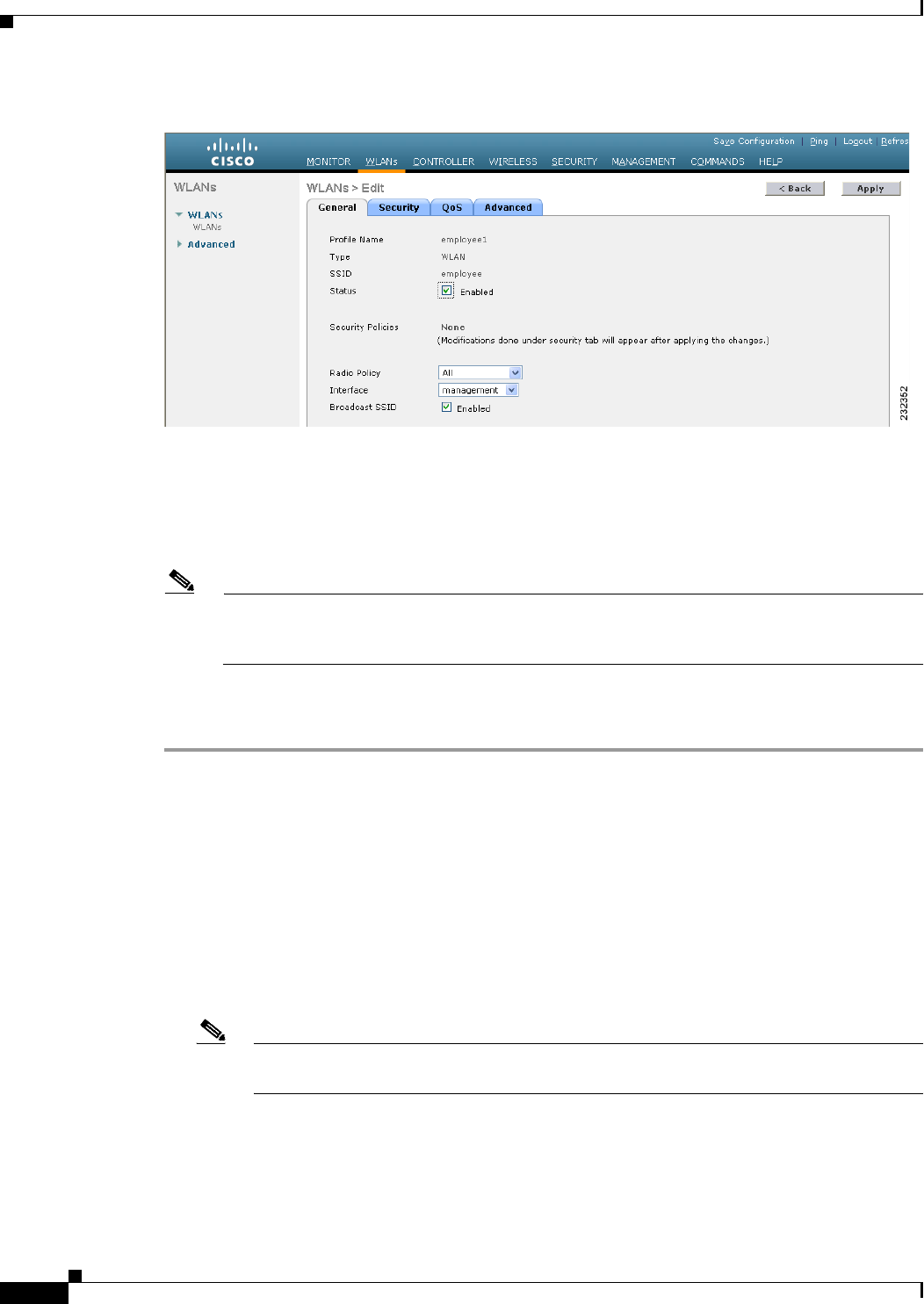
Figure 7-3 WLANs > Edit Page
Step 8 Use the parameters on the General, Security, QoS, and Advanced tabs to configure this WLAN. See the
sections in the rest of this chapter for instructions on configuring specific features for WLANs.
Step 9 On the General tab, select the Status check box to enable this WLAN. Be sure to leave it unselected until
you have finished making configuration changes to the WLAN.
Note You can also enable or disable WLANs from the WLANs page by selecting the check boxes to
the left of the WLANs that you want to enable or disable, choosing Enable Selected or Disable
Selected from the drop-down list, and clicking Go.
Step 10 Click Apply to commit your changes.
Step 11 Click Save Configuration to save your changes.
Using the CLI to Create WLANs
Use these commands to create WLANs using the controller CLI:
• View the list of existing WLANs and to see whether they are enabled or disabled by entering this
command:
show wlan summary
• Create a new WLAN by entering this command:
config wlan create wlan_id {profile_name | foreign_ap} ssid
Note If you do not specify an ssid, the profile_name parameter is used for both the profile name
and the SSID.

7-7
Cisco Wireless LAN Controller Configuration Guide
OL-21524-02
Chapter 7 Configuring WLANs
Configuring WLANs
Note When WLAN 1 is created in the configuration wizard, it is created in enabled mode. Disable
it until you have finished configuring it. When you create a new WLAN using the config
wlan create command, it is created in disabled mode. Leave it disabled until you have
finished configuring it.
Note If you want to create a guest LAN for wired guest users, follow the instructions in the
“Configuring Wired Guest Access” section on page 11-26.
• Disable a WLAN (for example, before making any modifications to a WLAN) by entering this
command:
config wlan disable {wlan_id | foreign_ap | all}
where
• wlan_id is a WLAN ID between 1 and 512.
• foreign_ap is a third-party access point.
• all is all WLANs.
Note If the management and AP-manager interfaces are mapped to the same port and are members
of the same VLAN, you must disable the WLAN before making a port-mapping change to
either interface. If the management and AP-manager interfaces are assigned to different
VLANs, you do not need to disable the WLAN.
• Enable a WLAN (for example, after you have finished making configuration changes to the WLAN)
by entering this command:
config wlan enable {wlan_id | foreign_ap | all}
Note If the command fails, an error message appears (for example, “Request failed for wlan 10 -
Static WEP key size does not match 802.1X WEP key size”).
• Delete a WLAN by entering this command:
config wlan delete {wlan_id | foreign_ap}
Note An error message appears if you try to delete a WLAN that is assigned to an access point
group. If you proceed, the WLAN is removed from the access point group and from the
access point’s radio.
Using the GUI to Search WLANs
You can search for specific WLANs in the list of up to 512 WLANs on the WLANs page. This feature
is especially useful if your WLANs span multiple pages, preventing you from viewing them all at once.
To search for WLANs using the controller GUI, follow these steps:

7-8
Cisco Wireless LAN Controller Configuration Guide
OL-21524-02
Chapter 7 Configuring WLANs
Configuring WLANs
Step 1 On the WLANs page, click Change Filter. The Search WLANs dialog box appears (see Figure 7-4).
Figure 7-4 Search WLANs Dialog Box
Step 2 Perform one of the following:
• To search for WLANs based on profile name, select the Profile Name check box and enter the
desired profile name in the edit box.
• To search for WLANs based on SSID, select the SSID check box and enter the desired SSID in the
edit box.
• To search for WLANs based on their status, select the Status check box and choose Enabled or
Disabled from the drop-down list.
Step 3 Click Find. Only the WLANs that match your search criteria appear on the WLANs page, and the
Current Filter field at the top of the page specifies the search criteria used to generate the list (for
example, None, Profile Name:user1, SSID:test1, Status: disabled).
Note To clear any configured search criteria and display the entire list of WLANs, click Clear Filter.
Configuring the Maximum Number of Clients per WLAN
You can set a limit to the number of clients that can connect to a WLAN, which is useful in scenarios
where you have a limited number of clients that can connect to a controller. For example, consider a
scenario where the controller can serve up to 256 clients on a WLAN and these clients can be shared
between enterprise users (employees) and guest users. You can set a limit on the number of guest clients
that can access a given WLAN. The number of clients that you can configure per WLAN depends on the
platform that you are using.
Note The maximum number of clients per WLAN feature is not supported when you use hybrid REAP local
authentication.
Note The maximum number of clients per WLAN feature is supported only for access points that are in
connected mode.
Table 7-1 describes the number of clients that you can configure for a given platform.

7-9
Cisco Wireless LAN Controller Configuration Guide
OL-21524-02
Chapter 7 Configuring WLANs
Configuring WLANs
Using the GUI to Configure the Maximum Number of Clients per WLAN
To configure the maximum number of clients per WLAN using the controller GUI, follow these steps:
Step 1 Choose WLANs to open the WLANs page.
Step 2 Click the ID number of the WLAN for which you want to limit the number of clients. The WLANs >
Edit page appears.
Step 3 On the Advanced tab, enter the Maximum Allowed Clients text box.
See Table 7-1 for the maximum number of clients supported per platform.
Step 4 Click Apply to commit your changes.
Using the CLI to Configure the Maximum Number of Clients per WLAN
To configure the maximum number of clients per WLAN using the controller CLI, follow these steps:
Step 1 Determine the WLAN ID for which you want to configure the maximum clients by entering this
command:
show wlan summary
Obtain the WLAN ID from the list.
Step 2 Configure the maximum number of clients per WLAN by entering this command:
config wlan max-associated-clients max-clients wlanid
See Table 7-1 for the maximum number of clients supported per platform.
Ta b l e 7-1 Maximum Clients per Platform.
Platform Maximum Number of Clients
Cisco 2106 Series Controller 350
Cisco 2500 Series Controller 500
Cisco 4400 Series Controller 5000
Cisco 5500 Series Controller 7000
Cisco Flex 7500 Series Controller 20000
WiSM2 10000

7-10
Cisco Wireless LAN Controller Configuration Guide
OL-21524-02
Chapter 7 Configuring WLANs
Configuring DHCP
Configuring DHCP
WLANs can be configured to use the same or different Dynamic Host Configuration Protocol (DHCP)
servers or no DHCP server. Two types of DHCP servers are available: internal and external.
Internal DHCP Server
The controllers contain an internal DHCP server. This server is typically used in branch offices that do
not already have a DHCP server. The wireless network generally contains 10 access points or fewer, with
the access points on the same IP subnet as the controller. The internal server provides DHCP addresses
to wireless clients, direct-connect access points, appliance-mode access points on the management
interface, and DHCP requests that are relayed from access points. Only lightweight access points are
supported. When you want to use the internal DHCP server, you must set the management interface IP
address of the controller as the DHCP server IP address.
DHCP option 43 is not supported on the internal server. Therefore, the access point must use an
alternative method to locate the management interface IP address of the controller, such as local subnet
broadcast, DNS, priming, or over-the-air discovery.
Note See Chapter 8, “Controlling Lightweight Access Points,” or the Controller Deployment Guide at this
URL for more information on how access points find controllers:
http://www.cisco.com/en/US/products/ps6366/prod_technical_reference_list.html
Note An internal DHCP server pool will only serve the wireless clients of that controller, not clients of other
controllers. Also, internal DHCP server can only serve wireless clients and not wired clients.
Note Starting in release 7.0.116.0 release, when the DHCP lease on the controller for internal DHCP server
is cleared, the associated access points reboots.
External DHCP Servers
The operating system is designed to appear as a DHCP Relay to the network and as a DHCP server to
clients with industry-standard external DHCP servers that support DHCP Relay, which means that each
controller appears as a DHCP Relay agent to the DHCP server and as a DHCP server at the virtual IP
address to wireless clients.
Because the controller captures the client IP address obtained from a DHCP server, it maintains the same
IP address for that client during intra-controller, inter-controller, and inter-subnet client roaming.
DHCP Assignment
You can configure DHCP on a per-interface or per-WLAN basis. The preferred method is to use the
primary DHCP server address assigned to a particular interface.

7-11
Cisco Wireless LAN Controller Configuration Guide
OL-21524-02
Chapter 7 Configuring WLANs
Configuring DHCP
Per-Interface Assignment
You can assign DHCP servers for individual interfaces. The management interface, AP-manager
interface, and dynamic interfaces can be configured for a primary and secondary DHCP server, and the
service-port interface can be configured to enable or disable DHCP servers.
Note See Chapter 10, “Managing Controller Software and Configurations,” for information on configuring the
controller’s interfaces.
Per-WLAN Assignment
You can also define a DHCP server on a WLAN. This server will override the DHCP server address on
the interface assigned to the WLAN.
Security Considerations
For enhanced security, we recommend that you require all clients to obtain their IP addresses from a
DHCP server. To enforce this requirement, all WLANs can be configured with a DHCP Addr.
Assignment Required setting, which disallows client static IP addresses. If DHCP Addr. Assignment
Required is selected, clients must obtain an IP address via DHCP. Any client with a static IP address is
not be allowed on the network. The controller monitors DHCP traffic because it acts as a DHCP proxy
for the clients.
Note WLANs that support management over wireless must allow management (device-servicing) clients to
obtain an IP address from a DHCP server. See the “Using Management over Wireless” section on
page 6-58 for instructions on configuring management over wireless.
If slightly less security is tolerable, you can create WLANs with DHCP Addr. Assignment Required
disabled. Clients then have the option of using a static IP address or obtaining an IP address from a
designated DHCP server.
Note DHCP Addr. Assignment Required is not supported for wired guest LANs.
You are also allowed to create separate WLANs with DHCP Addr. Assignment Required disabled and
then define the primary/secondary DHCP server as 0.0.0.0 on the interface assigned to the WLAN. These
WLANs drop all DHCP requests and force clients to use a static IP address. These WLANs do not
support management over wireless connections.
Note See Chapter 4, “Configuring Controller Settings,” for instructions on globally configuring DHCP proxy.
Note If you want to specify a static IP address for an access point rather than having one assigned
automatically by a DHCP server, see the “Configuring a Static IP Address on a Lightweight Access
Point” section on page 8-66 for more information.

7-12
Cisco Wireless LAN Controller Configuration Guide
OL-21524-02
Chapter 7 Configuring WLANs
Configuring DHCP
This section provides both GUI and CLI instructions for configuring DHCP.
Using the GUI to Configure DHCP
To configure DHCP using the controller GUI, follow these steps:
Step 1 Follow the instructions in the “Configuring the Management, AP-Manager, Virtual, and Service-Port
Interfaces” section on page 3-11 or “Using the GUI to Configure Dynamic Interfaces” section on
page 3-18 to configure a primary DHCP server for a management, AP-manager, or dynamic interface
that will be assigned to the WLAN.
Note When you want to use the internal DHCP server, you must set the management interface IP
address of the controller as the DHCP server IP address.
Step 2 Choose WLANs to open the WLANs page.
Step 3 Click the ID number of the WLAN for which you want to assign an interface. The WLANs > Edit
(General) page appears.
Step 4 On the General tab, unselect the Status check box and click Apply to disable the WLAN.
Step 5 Reclick the ID number of the WLAN.
Step 6 On the General tab, choose the interface for which you configured a primary DHCP server to be used
with this WLAN from the Interface drop-down list.
Step 7 Choose the Advanced tab to open the WLANs > Edit (Advanced) page.
Step 8 If you want to define a DHCP server on the WLAN that will override the DHCP server address on the
interface assigned to the WLAN, select the DHCP Server Override check box and enter the IP address
of the desired DHCP server in the DHCP Server IP Addr text box. The default value for the check box
is disabled.
Note The preferred method for configuring DHCP is to use the primary DHCP address assigned to a
particular interface instead of the DHCP server override.
Note DHCP Server override is applicable only for the default group.
Note If a WLAN has the DHCP server override option enabled and the controller has DHCP proxy
enabled, any interface mapped to the WLAN must have a DHCP server IP address or the WLAN
must be configured with a DHCP server IP address.
Step 9 If you want to require all clients to obtain their IP addresses from a DHCP server, select the DHCP Addr.
Assignment Required check box. When this feature is enabled, any client with a static IP address is not
allowed on the network. The default value is disabled.
Note DHCP Addr. Assignment Required is not supported for wired guest LANs.
Step 10 Click Apply to commit your changes.

7-13
Cisco Wireless LAN Controller Configuration Guide
OL-21524-02
Chapter 7 Configuring WLANs
Configuring DHCP
Step 11 On the General tab, select the Status check box and click Apply to reenable the WLAN.
Step 12 Click Save Configuration to save your changes.
Using the CLI to Configure DHCP
To configure DHCP using the controller CLI, follow these steps:
Step 1 Follow the instructions in the “Configuring the Management, AP-Manager, Virtual, and Service-Port
Interfaces” section on page 3-11 or “Using the GUI to Configure Dynamic Interfaces” section on
page 3-18 to configure a primary DHCP server for a management, AP-manager, or dynamic interface
that will be assigned to the WLAN.
Step 2 Disable the WLAN by entering this command:
config wlan disable wlan_id
Step 3 Specify the interface for which you configured a primary DHCP server to be used with this WLAN by
entering this command:
config wlan interface wlan_id interface_name
Step 4 If you want to define a DHCP server on the WLAN that will override the DHCP server address on the
interface assigned to the WLAN, enter this command:
config wlan dhcp_server wlan_id dhcp_server_ip_address
Note The preferred method for configuring DHCP is to use the primary DHCP address assigned to a
particular interface instead of the DHCP server override. If you enable the override, you can use
the show wlan command to verify that the DHCP server has been assigned to the WLAN.
Note If a WLAN has the DHCP server override option enabled and the controller has DHCP proxy
enabled, any interface mapped to the WLAN must have a DHCP server IP address or the WLAN
must be configured with a DHCP server IP address.
Step 5 Reenable the WLAN by entering this command:
config wlan enable wlan_id
Using the CLI to Debug DHCP
Use these CLI commands to obtain debug information:
• debug dhcp packet {enable | disable}—Enables or disables debugging of DHCP packets.
• debug dhcp message {enable | disable}—Enables or disables debugging of DHCP error messages.
• debug dhcp service-port {enable | disable}—Enables or disables debugging of DHCP packets on
the service port.
7-14
Cisco Wireless LAN Controller Configuration Guide
OL-21524-02
Chapter 7 Configuring WLANs
Configuring DHCP
Configuring DHCP Scopes
Controllers have built-in DHCP relay agents. However, when you desire network segments that do not
have a separate DHCP server, the controllers can have built-in DHCP scopes that assign IP addresses and
subnet masks to wireless clients. Typically, one controller can have one or more DHCP scopes that each
provide a range of IP addresses.
DHCP scopes are needed for internal DHCP to work. Once DHCP is defined on the controller, you can
then point the primary DHCP server IP address on the management, AP-manager, and dynamic
interfaces to the controller’s management interface. You can configure up to 16 DHCP scopes using the
controller GUI or CLI.
Using the GUI to Configure DHCP Scopes
To configure DHCP scopes using the controller GUI, follow these steps:
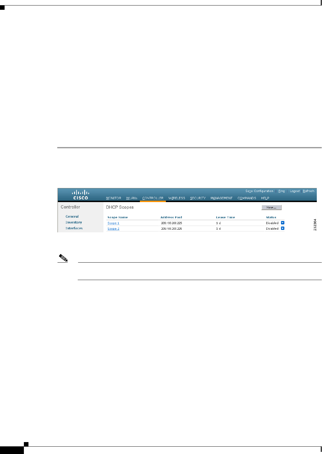
Step 1 Choose Controller > Internal DHCP Server > DHCP Scope to open the DHCP Scopes page (see
Figure 7-5).
Figure 7-5 DHCP Scopes Page
This page lists any DHCP scopes that have already been configured.
Note If you ever want to delete an existing DHCP scope, hover your cursor over the blue drop-down
arrow for that scope and choose Remove.
Step 2 Click New to add a new DHCP scope. The DHCP Scope > New page appears.
Step 3 In the Scope Name text box, enter a name for the new DHCP scope.
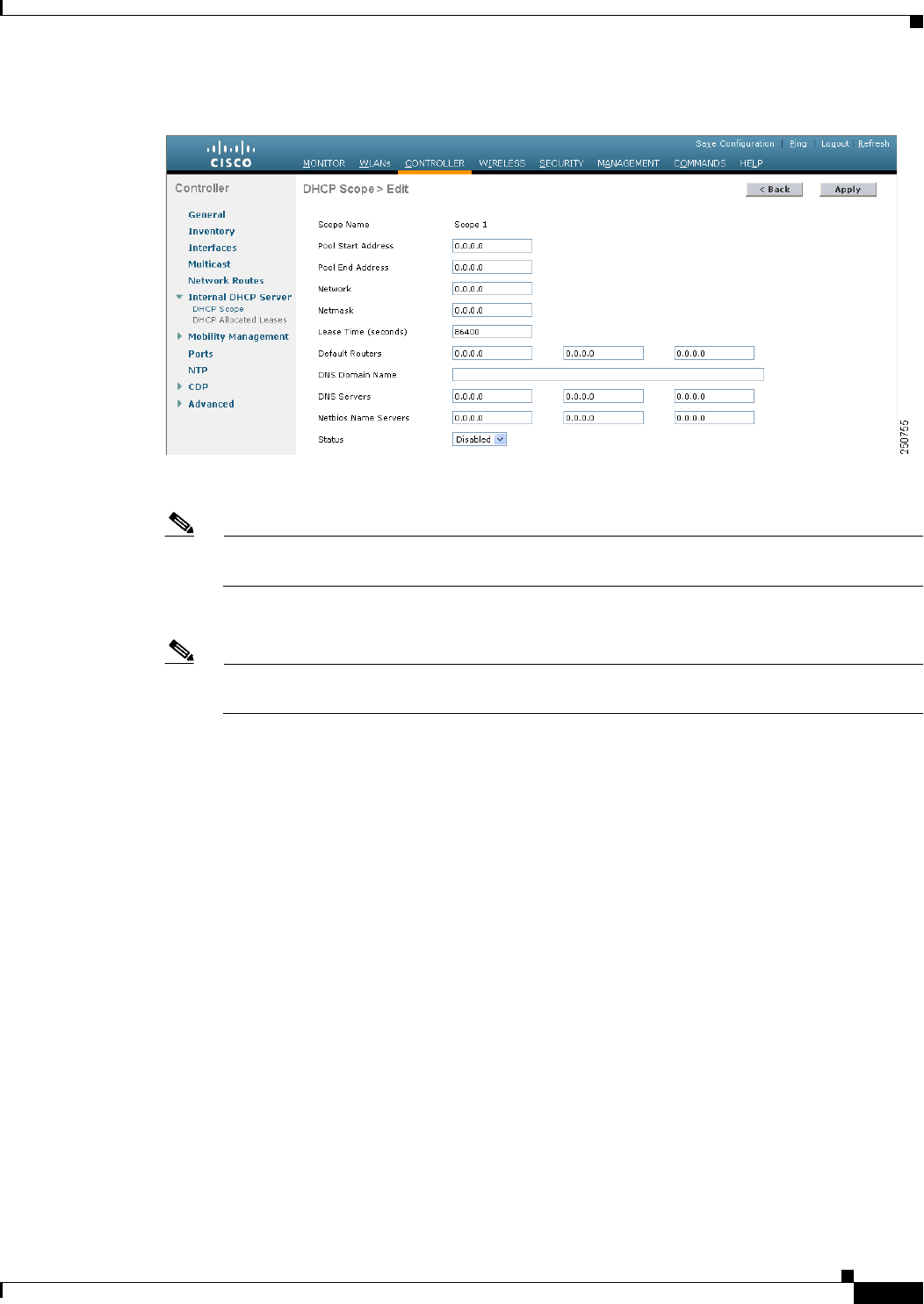
Step 4 Click Apply. When the DHCP Scopes page reappears, click the name of the new scope. The DHCP
Scope > Edit page appears (see Figure 7-6).
7-15
Cisco Wireless LAN Controller Configuration Guide
OL-21524-02
Chapter 7 Configuring WLANs
Configuring DHCP
Figure 7-6 DHCP Scope > Edit Page
Step 5 In the Pool Start Address text box, enter the starting IP address in the range assigned to the clients.
Note This pool must be unique for each DHCP scope and must not include the static IP addresses of
routers or other servers.
Step 6 In the Pool End Address text box, enter the ending IP address in the range assigned to the clients.
Note This pool must be unique for each DHCP scope and must not include the static IP addresses of
routers or other servers.
Step 7 In the Network text box, enter the network served by this DHCP scope. This IP address is used by the
management interface with Netmask applied, as configured on the Interfaces page.
Step 8 In the Netmask text box, enter the subnet mask assigned to all wireless clients.
Step 9 In the Lease Time text box, enter the amount of time (from 0 to 65536 seconds) that an IP address is
granted to a client.
Step 10 In the Default Routers text box, enter the IP address of the optional router connecting the controllers.
Each router must include a DHCP forwarding agent, which allows a single controller to serve the clients
of multiple controllers.
Step 11 In the DNS Domain Name text box, enter the optional domain name system (DNS) domain name of this
DHCP scope for use with one or more DNS servers.
Step 12 In the DNS Servers text box, enter the IP address of the optional DNS server. Each DNS server must be
able to update a client’s DNS entry to match the IP address assigned by this DHCP scope.
Step 13 In the Netbios Name Servers text box, enter the IP address of the optional Microsoft Network Basic Input
Output System (NetBIOS) name server, such as the Internet Naming Service (WINS) server.
Step 14 From the Status drop-down list, choose Enabled to enable this DHCP scope or choose Disabled to
disable it.
Step 15 Click Apply to commit your changes.
Step 16 Click Save Configuration to save your changes.

7-16
Cisco Wireless LAN Controller Configuration Guide
OL-21524-02
Chapter 7 Configuring WLANs
Configuring DHCP
Step 17 Choose DHCP Allocated Leases to see the remaining lease time for wireless clients. The DHCP
Allocated Lease page appears (see Figure 7-7), showing the MAC address, IP address, and remaining
lease time for the wireless clients.
Figure 7-7 DHCP Allocated Lease Page
Using the CLI to Configure DHCP Scopes
To configure DHCP scopes using the controller CLI, follow these steps:
Step 1 Create a new DHCP scope by entering this command:
config dhcp create-scope scope
Note If you ever want to delete a DHCP scope, enter this command: config dhcp delete-scope scope.
Step 2 Specify the starting and ending IP address in the range assigned to the clients by entering this command:
config dhcp address-pool scope start end
Note This pool must be unique for each DHCP scope and must not include the static IP addresses of
routers or other servers.
Step 3 Specify the network served by this DHCP scope (the IP address used by the management interface with
the Netmask applied) and the subnet mask assigned to all wireless clients by entering this command:
config dhcp network scope network netmask
Step 4 Specify the amount of time (from 0 to 65536 seconds) that an IP address is granted to a client by entering
this command:
config dhcp lease scope lease_duration
Step 5 Specify the IP address of the optional router connecting the controllers by entering this command:
config dhcp default-router scope router_1 [router_2] [router_3]
Each router must include a DHCP forwarding agent, which allows a single controller to serve the clients
of multiple controllers.
Step 6 Specify the optional domain name system (DNS) domain name of this DHCP scope for use with one or
more DNS servers by entering this command:
config dhcp domain scope domain
Step 7 Specify the IP address of the optional DNS server(s) by entering this command:

7-17
Cisco Wireless LAN Controller Configuration Guide
OL-21524-02
Chapter 7 Configuring WLANs
Configuring DHCP
config dhcp dns-servers scope dns1 [dns2] [dns3]
Each DNS server must be able to update a client’s DNS entry to match the IP address assigned by this
DHCP scope
Step 8 Specify the IP address of the optional Microsoft Network Basic Input Output System (NetBIOS) name
server, such as the Internet Naming Service (WINS) server by entering this command:
config dhcp netbios-name-server scope wins1 [wins2] [wins3]
Step 9 Enable or disable this DHCP scope by entering this command:
config dhcp {enable | disable} scope
Step 10 Save your changes by entering this command:
save config
Step 11 See the list of configured DHCP scopes by entering this command:
show dhcp summary
Information similar to the following appears:
Scope Name Enabled Address Range
Scope 1 No 0.0.0.0 -> 0.0.0.0
Scope 2 No 0.0.0.0 -> 0.0.0.0
Step 12 Display the DHCP information for a particular scope by entering this command:
show dhcp scope
Information similar to the following appears:
Enabled....................................... No
Lease Time.................................... 0
Pool Start.................................... 0.0.0.0
Pool End...................................... 0.0.0.0
Network....................................... 0.0.0.0
Netmask....................................... 0.0.0.0
Default Routers............................... 0.0.0.0 0.0.0.0 0.0.0.0
DNS Domain....................................
DNS........................................... 0.0.0.0 0.0.0.0 0.0.0.0
Netbios Name Servers.......................... 0.0.0.0 0.0.0.0 0.0.0.0
Configuring MAC Filtering for WLANs
When you use MAC filtering for client or administrator authorization, you need to enable it at the WLAN
level first. If you plan to use local MAC address filtering for any WLAN, use the commands in this
section to configure MAC filtering for a WLAN.
Enabling MAC Filtering
Use these commands to enable MAC filtering on a WLAN:
• Enable MAC filtering by entering the config wlan mac-filtering enable wlan_id command.
• Verify that you have MAC filtering enabled for the WLAN by entering the show wlan command.
When you enable MAC filtering, only the MAC addresses that you add to the WLAN are allowed to join
the WLAN. MAC addresses that have not been added are not allowed to join the WLAN.

7-18
Cisco Wireless LAN Controller Configuration Guide
OL-21524-02
Chapter 7 Configuring WLANs
Configuring DHCP
Creating a Local MAC Filter
Controllers have built-in MAC filtering capability, similar to that provided by a RADIUS authorization
server.
Use these commands to add MAC addresses to a WLAN MAC filter:
• Create a MAC filter entry on the controller by entering the config macfilter add mac_addr wlan_id
[interface_name] [description] [IP_addr] command.
The following parameters are optional:
–
mac_addr—MAC address of the client.
–
wlan_id—WLAN id on which the client is associating.
–
interface_name—The name of the interface. This interface name is used to override the
interface configured to the WLAN.
Note You must have AAA enabled on the WLAN to override the interface name.
–
description—A brief description of the interface in double quotes (for example, “Interface1”).
–
IP_addr—The IP address which is used for a passive client with the MAC address specified by
the mac addr value above.
• Assign an IP address to an existing MAC filter entry, if one was not assigned in the config macfilter
add command by entering the config macfilter ip-address mac_addr IP_addr command.
• Verify that MAC addresses are assigned to the WLAN by entering the show macfilter command.
Configuring a Timeout for Disabled Clients
You can configure a timeout for disabled clients. Clients who fail to authenticate three times when
attempting to associate are automatically disabled from further association attempts. After the timeout
period expires, the client is allowed to retry authentication until it associates or fails authentication and
is excluded again. Use these commands to configure a timeout for disabled clients:
• Configure the timeout for disabled clients by entering the config wlan exclusionlist wlan_id timeout
command. Enter a timeout from 1 to 65535 seconds, or enter 0 to permanently disable the client.
• Verify the current timeout by entering the show wlan command.
Assigning WLANs to Interfaces
Use these commands to assign a WLAN to an interface:
• Assign a WLAN to an interface by entering this command:
config wlan interface {wlan_id | foreignAp} interface_id
–
Use the interface_id option to assign the WLAN to a specific interface.
–
Use the foreignAp option to use a third-party access point.
• Verify the interface assignment status by entering the show wlan summary command.

7-19
Cisco Wireless LAN Controller Configuration Guide
OL-21524-02
Chapter 7 Configuring WLANs
Configuring DHCP
Configuring the DTIM Period
In 802.11a/n and 802.11b/g/n networks, lightweight access points broadcast a beacon at regular
intervals, which coincides with the Delivery Traffic Indication Map (DTIM). After the access point
broadcasts the beacon, it transmits any buffered broadcast and multicast frames based on the value set
for the DTIM period. This feature allows power-saving clients to wake up at the appropriate time if they
are expecting broadcast or multicast data.
Typically, the DTIM value is set to 1 (transmit broadcast and multicast frames after every beacon) or 2
(transmit after every other beacon). For instance, if the beacon period of the 802.11a/n or 802.11b/g/n
network is 100 ms and the DTIM value is set to 1, the access point transmits buffered broadcast and
multicast frames 10 times per second. If the beacon period is 100 ms and the DTIM value is set to 2, the
access point transmits buffered broadcast and multicast frames 5 times per second. Either of these
settings may be suitable for applications, including VoIP, that expect frequent broadcast and multicast
frames.
However, the DTIM value can be set as high as 255 (transmit broadcast and multicast frames after every
255th beacon) if all 802.11a/n or 802.11b/g/n clients have power save enabled. Because the clients have
to listen only when the DTIM period is reached, they can be set to listen for broadcasts and multicasts
less frequently, resulting in a longer battery life. For instance, if the beacon period is 100 ms and the
DTIM value is set to 100, the access point transmits buffered broadcast and multicast frames once every
10 seconds, allowing the power-saving clients to sleep longer before they have to wake up and listen for
broadcasts and multicasts, resulting in a longer battery life.
Note The beacon period in controllers is listed in terms of milliseconds. The beacon period can also be
measured in time units, where one time unit equals 1024 microseconds or 102.4 milliseconds. If a beacon
interval is listed as 100 milliseconds in a controller, it is only a rounded off value for 102.4 milliseconds.
Due to hardware limitation in certain radios, even though the beacon interval is, say 100 time units, it is
adjusted to 102 time units, which roughly equals 1044.48 milliseconds. When the beacon period is to be
represented in terms of time units, the value is adjusted to the nearest multiple of 17.
Many applications cannot tolerate a long time between broadcast and multicast messages, which results
in poor protocol and application performance. We recommend a low DTIM value for 802.11a/n and
802.11b/g/n networks that support such clients.
In controller software release 5.0 or later releases, you can configure the DTIM period for the 802.11a/n
and 802.11b/g/n radio networks on specific WLANs. In previous software releases, the DTIM period was
configured per radio network only, not per WLAN. The benefit of this change is that now you can
configure a different DTIM period for each WLAN. For example, you might want to set different DTIM
values for voice and data WLANs.
Note When you upgrade the controller software to release 5.0 or later releases, the DTIM period that was
configured for a radio network is copied to all of the existing WLANs on the controller.
Using the GUI to Configure the DTIM Period
To configure the DTIM period for a WLAN using the controller GUI, follow these steps:
Step 1 Choose WLANs to open the WLANs page.
Step 2 Click the ID number of the WLAN for which you want to configure the DTIM period.
7-20
Cisco Wireless LAN Controller Configuration Guide
OL-21524-02
Chapter 7 Configuring WLANs
Configuring DHCP
Step 3 Unselect the Status check box to disable the WLAN.
Step 4 Click Apply to commit your changes.
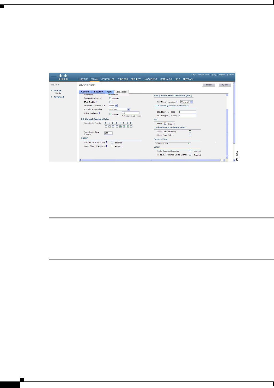
Step 5 Choose the Advanced tab to open the WLANs > Edit (Advanced) page (see Figure 7-8).
Figure 7-8 WLANs > Edit (Advanced) Page
Step 6 Under DTIM Period, enter a value between 1 and 255 (inclusive) in the 802.11a/n and 802.11b/g/n text
boxes. The default value is 1 (transmit broadcast and multicast frames after every beacon).
Step 7 Click Apply to commit your changes.
Step 8 Choose the General tab to open the WLANs > Edit (General) page.
Step 9 Select the Status check box to reenable the WLAN.
Step 10 Click Save Configuration to save your changes.
Using the CLI to Configure the DTIM Period
To configure the DTIM period for a WLAN using the controller CLI, follow these steps:
Step 1 Disable the WLAN by entering this command:
config wlan disable wlan_id
Step 2 Configure the DTIM period for either the 802.11a/n or 802.11b/g/n radio network on a specific WLAN
by entering this command:
config wlan dtim {802.11a | 802.11b} dtim wlan_id
where dtim is a value between 1 and 255 (inclusive). The default value is 1 (transmit broadcast and
multicast frames after every beacon).
Step 3 Reenable the WLAN by entering this command:
config wlan enable wlan_id
Step 4 Save your changes by entering this command:
save config
Step 5 Verify the DTIM period by entering this command:

7-21
Cisco Wireless LAN Controller Configuration Guide
OL-21524-02
Chapter 7 Configuring WLANs
Configuring DHCP
show wlan wlan_id
Information similar to the following appears:
WLAN Identifier.................................. 1
Profile Name..................................... employee1
Network Name (SSID).............................. employee
Status........................................... Enabled
...
DTIM period for 802.11a radio.................... 1
DTIM period for 802.11b radio.................... 1
Local EAP Authentication...................... Disabled
...
Configuring Peer-to-Peer Blocking
In controller software releases prior to 4.2, peer-to-peer blocking is applied globally to all clients on all
WLANs and causes traffic between two clients on the same VLAN to be transferred to the upstream
VLAN rather than being bridged by the controller. This behavior usually results in traffic being dropped
at the upstream switch because switches do not forward packets out the same port on which they are
received.
In controller software release 4.2 or later releases, peer-to-peer blocking is applied to individual
WLANs, and each client inherits the peer-to-peer blocking setting of the WLAN to which it is
associated. In software release 4.2 or later releases, you also have more control over how traffic is
directed. For example, you can choose to have traffic bridged locally within the controller, dropped by
the controller, or forwarded to the upstream VLAN. Figure 7-9 shows each option.
7-22
Cisco Wireless LAN Controller Configuration Guide
OL-21524-02
Chapter 7 Configuring WLANs
Configuring DHCP
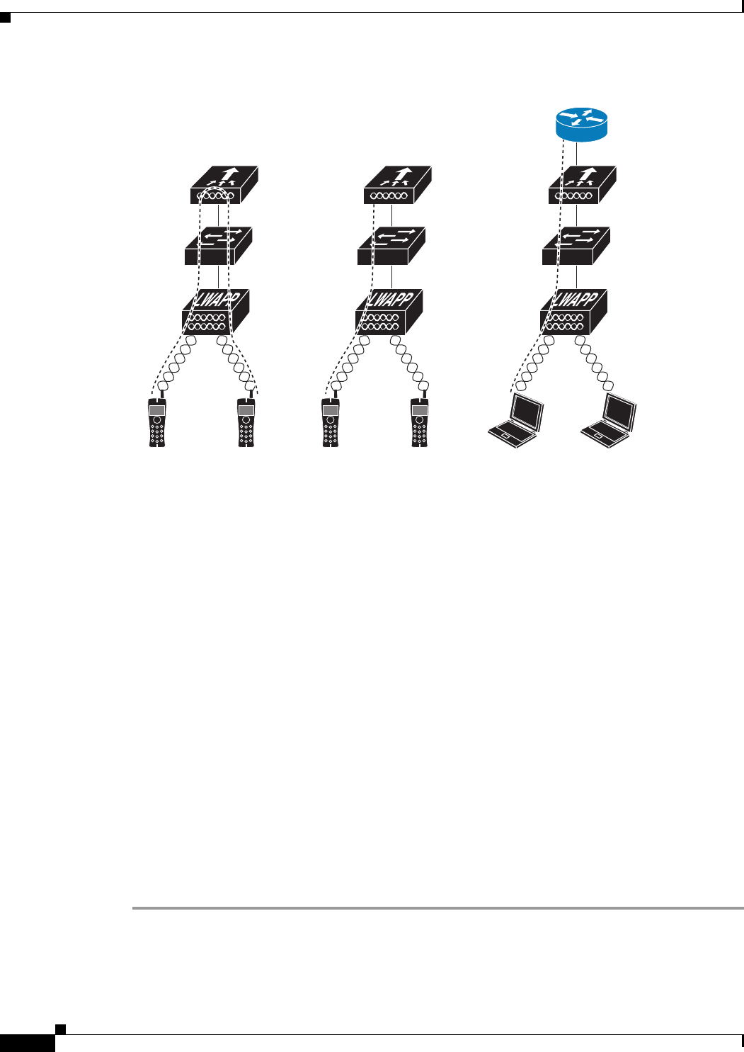
Figure 7-9 Peer-to-Peer Blocking Examples
Guidelines for Using Peer-to-Peer Blocking
Follow these guidelines when using peer-to-peer blocking:
• In controller software releases prior to 4.2, the controller forwards Address Resolution Protocol
(ARP) requests upstream (just like all other traffic). In controller software release 4.2 or later
releases, ARP requests are directed according to the behavior set for peer-to-peer blocking.
• Peer-to-peer blocking does not apply to multicast traffic.
• Locally switched hybrid-REAP WLANs and hybrid-REAP access points in standalone mode do not
support peer-to-peer blocking.
• If you upgrade to controller software release 4.2 or later releases from a previous release that
supports global peer-to-peer blocking, each WLAN is configured with the peer-to-peer blocking
action of forwarding traffic to the upstream VLAN.
Using the GUI to Configure Peer-to-Peer Blocking
To configure a WLAN for peer-to-peer blocking using the controller GUI, follow these steps:
Step 1 Choose WLANs to open the WLANs page.
Step 2 Click the ID number of the WLAN for which you want to configure peer-to-peer blocking.
Step 3 Choose the Advanced tab to open the WLANs > Edit (Advanced) page (see Figure 7-10).
232321
WLAN 1 WLAN 1 WLAN 2 WLAN 2 WLAN 3 WLAN 3
Disable:
Peer-to-peer blocking
is disabled, and traffic
is bridged.
Drop:
Packets are discarded
by the controller.
Forward Up:
Packets are forwarded
to the upstream switch.
Layer 3
Router/Switch
Controller
Layer 2 Switch
Lightweight
Access Point
7-23
Cisco Wireless LAN Controller Configuration Guide
OL-21524-02
Chapter 7 Configuring WLANs
Configuring DHCP
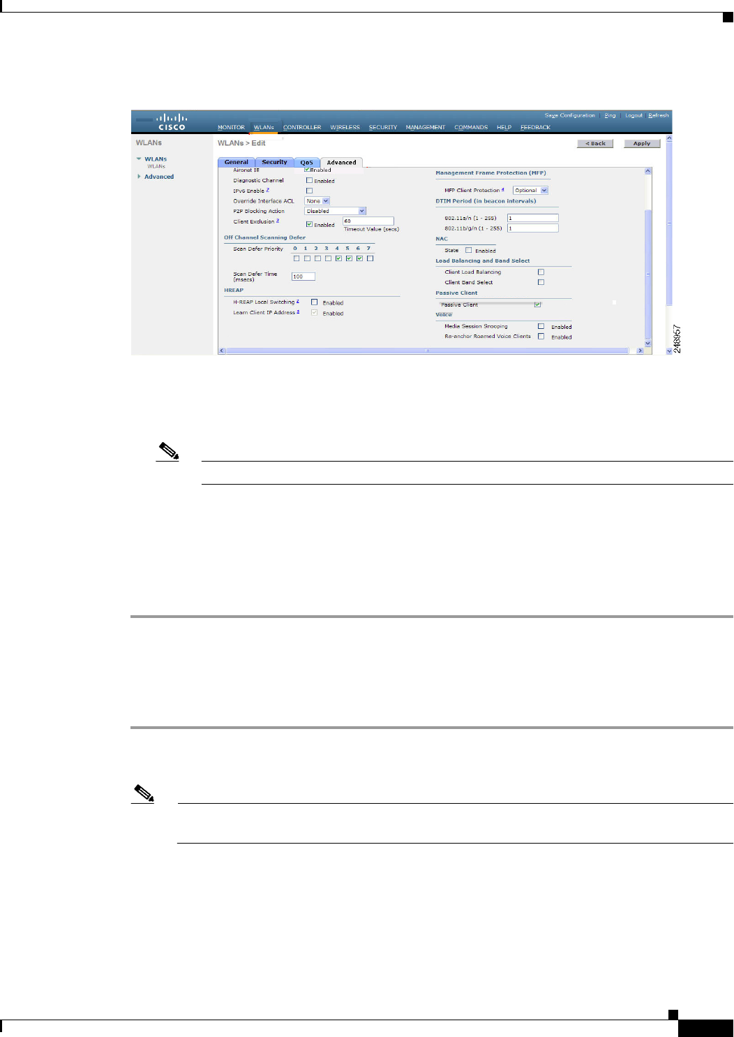
Figure 7-10 WLANs > Edit (Advanced) Page
Step 4 Choose one of the following options from the P2P Blocking drop-down list:
• Disabled—Disables peer-to-peer blocking and bridges traffic locally within the controller whenever
possible. This is the default value.
Note Traffic is never bridged across VLANs in the controller.
• Drop—Causes the controller to discard the packets.
• Forward-UpStream—Causes the packets to be forwarded on the upstream VLAN. The device
above the controller decides what action to take regarding the packets.
Step 5 Click Apply to commit your changes.
Step 6 Click Save Configuration to save your changes.
Using the CLI to Configure Peer-to-Peer Blocking
To configure a WLAN for peer-to-peer blocking using the controller CLI, follow these steps:
Step 1 Configure a WLAN for peer-to-peer blocking by entering this command:
config wlan peer-blocking {disable | drop | forward-upstream} wlan_id
Note See the description of each parameter in the “Using the GUI to Configure Peer-to-Peer
Blocking” section above.
Step 2 Save your changes by entering this command:
save config
Step 3 See the status of peer-to-peer blocking for a WLAN by entering this command:
show wlan wlan_id
Information similar to the following appears:

7-24
Cisco Wireless LAN Controller Configuration Guide
OL-21524-02
Chapter 7 Configuring WLANs
Configuring DHCP
WLAN Identifier.................................. 1
Profile Name..................................... test
Network Name (SSID).............................. test
Status........................................... Enabled
...
...
...
Peer-to-Peer Blocking Action..................... Disabled
Radio Policy..................................... All
Local EAP Authentication...................... Disabled
Configuring Layer 2 Security
This section describes how to assign Layer 2 security settings to WLANs.
Static WEP Keys
Controllers can control static WEP keys across access points. Use these commands to configure static
WEP for WLANs:
• Disable the 802.1X encryption by entering this command:
config wlan security 802.1X disable wlan_id
• Configure 40/64-bit or 104/128-bit WEP keys by entering this command:
config wlan security static-wep-key encryption wlan_id {40 | 104} {hex | ascii} key key_index
–
Use the 40 or 104 option to specify 40/64-bit or 104/128-bit encryption. The default setting is
104/128.
–
Use the hex or ascii option to specify the character format for the WEP key.
–
Enter 10 hexadecimal digits (any combination of 0-9, a-f, or A-F) or five printable ASCII
characters for 40-bit/64-bit WEP keys or enter 26 hexadecimal or 13 ASCII characters for
104-bit/128-bit keys.
–
Enter a key index (sometimes called a key slot). The default value is 0, which corresponds to a
key index of 1; the valid values are 0 to 3 (key index of 1 to 4).
Dynamic 802.1X Keys and Authorization
Controllers can control 802.1X dynamic WEP keys using Extensible Authentication Protocol (EAP)
across access points and support 802.1X dynamic key settings for WLANs.
Note To use LEAP with lightweight access points and wireless clients, make sure to choose Cisco-Aironet as
the RADIUS server type when configuring the CiscoSecure Access Control Server (ACS).
• Check the security settings of each WLAN by entering this command:
show wlan wlan_id
The default security setting for new WLANs is 802.1X with dynamic keys enabled. To maintain
robust Layer 2 security, leave 802.1X configured on your WLANs.
• Disable or enable the 802.1X authentication by entering this command:

7-25
Cisco Wireless LAN Controller Configuration Guide
OL-21524-02
Chapter 7 Configuring WLANs
Configuring DHCP
config wlan security 802.1X {enable | disable} wlan_id
After you enable 802.1X authentication, the controller sends EAP authentication packets between
the wireless client and the authentication server. This command allows all EAP-type packets to be
sent to and from the controller.
• Change the 802.1X encryption level for a WLAN by entering this command:
config wlan security 802.1X encryption wlan_id [0 | 40 | 104]
–
Use the 0 option to specify no 802.1X encryption.
–
Use the 40 option to specify 40/64-bit encryption.
–
Use the 104 option to specify 104/128-bit encryption. (This is the default encryption setting.)
Configuring a WLAN for Both Static and Dynamic WEP
You can configure up to four WLANs to support static WEP keys, and you can also configure dynamic
WEP on any of these static-WEP WLANs. Follow these guidelines when configuring a WLAN for both
static and dynamic WEP:
• The static WEP key and the dynamic WEP key must be the same length.
• When you configure both static and dynamic WEP as the Layer 2 security policy, no other security
policies can be specified. That is, you cannot configure web authentication. However, when you
configure either static or dynamic WEP as the Layer 2 security policy, you can configure web
authentication.
WPA1 and WPA2
Wi-Fi Protected Access (WPA or WPA1) and WPA2 are standards-based security solutions from the
Wi-Fi Alliance that provide data protection and access control for wireless LAN systems. WPA1 is
compatible with the IEEE 802.11i standard but was implemented prior to the standard’s ratification;
WPA2 is the Wi-Fi Alliance's implementation of the ratified IEEE 802.11i standard.
By default, WPA1 uses Temporal Key Integrity Protocol (TKIP) and message integrity check (MIC) for
data protection while WPA2 uses the stronger Advanced Encryption Standard encryption algorithm
using Counter Mode with Cipher Block Chaining Message Authentication Code Protocol (AES-CCMP).
Both WPA1 and WPA2 use 802.1X for authenticated key management by default. However, these
options are also available:
• 802.1X—The standard for wireless LAN security, as defined by IEEE, is called 802.1X for 802.11,
or simply 802.1X. An access point that supports 802.1X acts as the interface between a wireless
client and an authentication server, such as a RADIUS server, to which the access point
communicates over the wired network. If 802.1X is selected, only 802.1X clients are supported.
• PSK—When you choose PSK (also known as WPA preshared key or WPA passphrase), you need to
configure a preshared key (or a passphrase). This key is used as the pairwise master key (PMK)
between the clients and the authentication server.
• CCKM—Cisco Centralized Key Management (CCKM) uses a fast rekeying technique that enables
clients to roam from one access point to another without going through the controller, typically in
under 150 milliseconds (ms). CCKM reduces the time required by the client to mutually authenticate
with the new access point and derive a new session key during reassociation. CCKM fast secure
roaming ensures that there is no perceptible delay in time-sensitive applications such as wireless
Voice over IP (VoIP), enterprise resource planning (ERP), or Citrix-based solutions. CCKM is a
CCXv4-compliant feature. If CCKM is selected, only CCKM clients are supported.

7-26
Cisco Wireless LAN Controller Configuration Guide
OL-21524-02
Chapter 7 Configuring WLANs
Configuring DHCP
When CCKM is enabled, the behavior of access points differs from the controller's for fast roaming
in the following ways:
–
If an association request sent by a client has CCKM enabled in a Robust Secure Network
Information Element (RSN IE) but CCKM IE is not encoded and only PMKID is encoded in
RSN IE, then the controller does not do a full authentication. Instead, the controller validates
the PMKID and does a four-way handshake.
–
If an association request sent by a client has CCKM enabled in RSN IE but CCKM IE is not
encoded and only PMKID is encoded in RSN IE, then AP does a full authentication. The access
point does not use PMKID sent with the association request when CCKM is enabled in RSN IE.
Note The OEAP 600 series does not support fast roaming for clients. Dual mode voice clients will
experience reduced call quality when they roam between the two spectrums on OEAP602 access
point. We recommend that you configure voice devices to only connect on one band, either 2.4
GHz or 5.0 GHz.
Note The 4.2 or later release of controller software supports CCX versions 1 through 5. CCX
support is enabled automatically for every WLAN on the controller and cannot be disabled.
The controller stores the CCX version of the client in its client database and uses it to limit
client functionality. Clients must support CCXv4 or v5 in order to use CCKM. See the
“Configuring Cisco Client Extensions” section on page 7-52 for more information on CCX.
• 802.1X+CCKM—During normal operation, 802.1X-enabled clients mutually authenticate with a
new access point by performing a complete 802.1X authentication, including communication with
the main RADIUS server. However, when you configure your WLAN for 802.1X and CCKM fast
secure roaming, CCKM-enabled clients securely roam from one access point to another without the
need to reauthenticate to the RADIUS server. 802.1X+CCKM is considered optional CCKM
because both CCKM and non-CCKM clients are supported when this option is selected.
On a single WLAN, you can allow WPA1, WPA2, and 802.1X/PSK/CCKM/802.1X+CCKM clients to
join. All of the access points on such a WLAN advertise WPA1, WPA2, and 802.1X/PSK/CCKM/
802.1X+CCKM information elements in their beacons and probe responses. When you enable WPA1
and/or WPA2, you can also enable one or two ciphers, or cryptographic algorithms, designed to protect
data traffic. Specifically, you can enable AES and/or TKIP data encryption for WPA1 and/or WPA2.
TKIP is the default value for WPA1, and AES is the default value for WPA2.
You can configure WPA1+WPA2 through either the GUI or the CLI.
Using the GUI to Configure WPA1+WPA2
To configure a WLAN for WPA1+WPA2 using the controller GUI, follow these steps:
Step 1 Choose WLANs to open the WLANs page.
Step 2 Click the ID number of the desired WLAN to open the WLANs > Edit page.
Step 3 Choose the Security and Layer 2 tabs to open the WLANs > Edit (Security > Layer 2) page (see
Figure 7-11).
7-27
Cisco Wireless LAN Controller Configuration Guide
OL-21524-02
Chapter 7 Configuring WLANs
Configuring DHCP
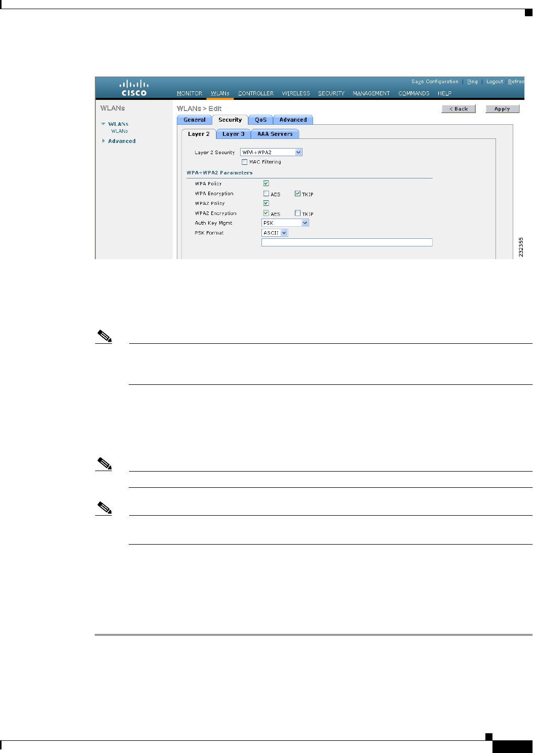
Figure 7-11 WLANs > Edit (Security > Layer 2) Page
Step 4 Choose WPA+WPA2 from the Layer 2 Security drop-down list.
Step 5 Under WPA+WPA2 Parameters, select the WPA Policy check box to enable WPA1, select the WPA2
Policy check box to enable WPA2, or select both check boxes to enable both WPA1 and WPA2.
Note The default value is disabled for both WPA1 and WPA2. If you leave both WPA1 and WPA2
disabled, the access points advertise in their beacons and probe responses information elements
only for the authentication key management method that you choose in Step 7.
Step 6 Select the AES check box to enable AES data encryption or the TKIP check box to enable TKIP data
encryption for WPA1, WPA2, or both. The default values are TKIP for WPA1 and AES for WPA2.
Step 7 Choose one of the following key management methods from the Auth Key Mgmt drop-down list:
802.1X, CCKM, PSK, or 802.1X+CCKM.
Note Cisco OEAP 600 does not support CCKM. You must choose either 802.1X or PSK.
Note For Cisco OEAP 600, the TKIP and AES security encryption settings must be identical for WPA
and WPA2.
Step 8 If you chose PSK in Step 7, choose ASCII or HEX from the PSK Format drop-down list and then enter
a preshared key in the blank text box. WPA preshared keys must contain 8 to 63 ASCII text characters
or 64 hexadecimal characters.
Step 9 Click Apply to commit your changes.
Step 10 Click Save Configuration to save your changes.
Using the CLI to Configure WPA1+WPA2
To configure a WLAN for WPA1+WPA2 using the controller CLI, follow these steps:

7-28
Cisco Wireless LAN Controller Configuration Guide
OL-21524-02
Chapter 7 Configuring WLANs
Configuring DHCP
Step 1 Disable the WLAN by entering this command:
config wlan disable wlan_id
Step 2 Enable or disable WPA for the WLAN by entering this command:
config wlan security wpa {enable | disable} wlan_id
Step 3 Enable or disable WPA1 for the WLAN by entering this command:
config wlan security wpa wpa1 {enable | disable} wlan_id
Step 4 Enable or disable WPA2 for the WLAN by entering this command:
config wlan security wpa wpa2 {enable | disable} wlan_id
Step 5 Enable or disable AES or TKIP data encryption for WPA1 or WPA2 by entering one of these commands:
• config wlan security wpa wpa1 ciphers {aes | tkip} {enable | disable} wlan_id
• config wlan security wpa wpa2 ciphers {aes | tkip} {enable | disable} wlan_id
The default values are TKIP for WPA1 and AES for WPA2.
Step 6 Enable or disable 802.1X, PSK, or CCKM authenticated key management by entering this command:
config wlan security wpa akm {802.1X | psk | cckm} {enable | disable} wlan_id
The default value is 802.1X.
Step 7 If you enabled PSK in Step 6, enter this command to specify a preshared key:
config wlan security wpa akm psk set-key {ascii | hex} psk-key wlan_id
WPA preshared keys must contain 8 to 63 ASCII text characters or 64 hexadecimal characters.
Step 8 If you enabled WPA2 with 802.1X authenticated key management or WPA1 or WPA2 with CCKM
authenticated key management, the PMK cache lifetime timer is used to trigger reauthentication with the
client when necessary. The timer is based on the timeout value received from the AAA server or the
WLAN session timeout setting. To see the amount of time remaining before the timer expires, enter this
command:
show pmk-cache all
Information similar to the following appears:
PMK-CCKM Cache
Entry
Type Station Lifetime VLAN Override IP Override
------ ------------------- -------- ------------------ ---------------
CCKM 00:07:0e:b9:3a:1b 150 0.0.0.0
If you enabled WPA2 with 802.1X authenticated key management, the controller supports opportunistic
PMKID caching but not sticky (or non-opportunistic) PMKID caching. In sticky PMKID caching, the
client stores multiple PMKIDs. This approach is not practical because it requires full authentication for
each new access point and is not guaranteed to work in all conditions. In contrast, opportunistic PMKID
caching stores only one PMKID per client and is not subject to the limitations of sticky PMK caching.
Step 9 Enable the WLAN by entering this command:
config wlan enable wlan_id
Step 10 Save your settings by entering this command:
save config

7-29
Cisco Wireless LAN Controller Configuration Guide
OL-21524-02
Chapter 7 Configuring WLANs
Configuring DHCP
CKIP
Cisco Key Integrity Protocol (CKIP) is a Cisco-proprietary security protocol for encrypting 802.11
media. CKIP improves 802.11 security in infrastructure mode using key permutation, a message
integrity check (MIC), and a message sequence number. Software release 4.0 or later releases support
CKIP with a static key. For this feature to operate correctly, you must enable Aironet information
elements (IEs) for the WLAN.
A lightweight access point advertises support for CKIP in beacon and probe response packets by adding
an Aironet IE and setting one or both of the CKIP negotiation bits (key permutation and multi-modular
hash message integrity check [MMH MIC]). Key permutation is a data encryption technique that uses
the basic encryption key and the current initialization vector (IV) to create a new key. MMH MIC
prevents bit-flip attacks on encrypted packets by using a hash function to compute message integrity
code.
The CKIP settings specified in a WLAN are mandatory for any client attempting to associate. If the
WLAN is configured for both CKIP key permutation and MMH MIC, the client must support both. If
the WLAN is configured for only one of these features, the client must support only the CKIP feature.
CKIP requires that 5-byte and 13-byte encryption keys be expanded to 16-byte keys. The algorithm to
perform key expansion occurs at the access point. The key is appended to itself repeatedly until the
length reaches 16 bytes. All lightweight access points support CKIP.
You can configure CKIP through either the GUI or the CLI.
Using the GUI to Configure CKIP
To configure a WLAN for CKIP using the controller GUI, follow these steps:
Step 1 Choose WLANs to open the WLANs page.
Step 2 Click the ID number of the desired WLAN to open the WLANs > Edit page.
Step 3 Choose the Advanced tab.
Step 4 Select the Aironet IE check box to enable Aironet IEs for this WLAN and click Apply.
Step 5 Choose the General tab.
Step 6 Unselect the Status check box, if selected, to disable this WLAN and click Apply.
Step 7 Choose the Security and Layer 2 tabs to open the WLANs > Edit (Security > Layer 2) page (see
Figure 7-12).
7-30
Cisco Wireless LAN Controller Configuration Guide
OL-21524-02
Chapter 7 Configuring WLANs
Configuring DHCP
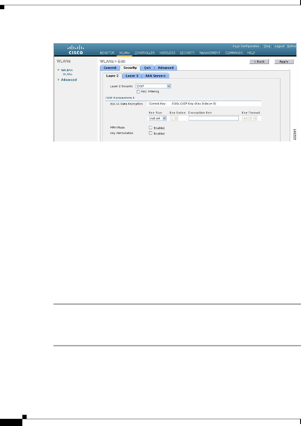
Figure 7-12 WLANs > Edit (Security > Layer 2) Page
Step 8 Choose CKIP from the Layer 2 Security drop-down list.
Step 9 Under CKIP Parameters, choose the length of the CKIP encryption key from the Key Size drop-down
list.The range is Not Set, 40 bits, or 104 bits and the default is Not Set.
Step 10 Choose the number to be assigned to this key from the Key Index drop-down list. You can configure up
to four keys.
Step 11 From the Key Format drop-down list, choose ASCII or HEX and then enter an encryption key in the
Encryption Key text box. 40-bit keys must contain 5 ASCII text characters or 10 hexadecimal characters.
104-bit keys must contain 13 ASCII text characters or 26 hexadecimal characters.
Step 12 Select the MMH Mode check box to enable MMH MIC data protection for this WLAN. The default
value is disabled (or unselected).
Step 13 Select the Key Permutation check box to enable this form of CKIP data protection. The default value
is disabled (or unselected).
Step 14 Click Apply to commit your changes.
Step 15 Choose the General tab.
Step 16 Select the Status check box to enable this WLAN.
Step 17 Click Apply to commit your changes.
Step 18 Click Save Configuration to save your changes.
Using the CLI to Configure CKIP
To configure a WLAN for CKIP using the controller CLI, follow these steps:
Step 1 Disable the WLAN by entering this command:
config wlan disable wlan_id
Step 2 Enable Aironet IEs for this WLAN by entering this command:
config wlan ccx aironet-ie enable wlan_id
Step 3 Enable or disable CKIP for the WLAN by entering this command:

7-31
Cisco Wireless LAN Controller Configuration Guide
OL-21524-02
Chapter 7 Configuring WLANs
Configuring DHCP
config wlan security ckip {enable | disable} wlan_id
Step 4 Specify a CKIP encryption key for the WLAN by entering this command:
config wlan security ckip akm psk set-key wlan_id {40 | 104} {hex | ascii} key key_index
Step 5 Enable or disable CKIP MMH MIC for the WLAN by entering this command:
config wlan security ckip mmh-mic {enable | disable} wlan_id
Step 6 Enable or disable CKIP key permutation for the WLAN by entering this command:
config wlan security ckip kp {enable | disable} wlan_id
Step 7 Enable the WLAN by entering this command:
config wlan enable wlan_id
Step 8 Save your settings by entering this command:
save config
Configuring a Session Timeout
Using the controller GUI or CLI, you can configure a session timeout for wireless clients on a WLAN.
The session timeout is the maximum time for a client session to remain active before requiring
reauthorization.
Using the GUI to Configure a Session Timeout
To configure a session timeout for wireless clients on a WLAN using the controller GUI, follow these
steps:
Step 1 Choose WLANs to open the WLANs page.
Step 2 Click the ID number of the WLAN for which you want to assign a session timeout.
Step 3 When the WLANs > Edit page appears, choose the Advanced tab. The WLANs > Edit (Advanced) page
appears.
Step 4 Select the Enable Session Timeout check box to configure a session timeout for this WLAN. Otherwise,
unselect the check box. The default value is selected.
In the Session Timeout text box, enter a value between 300 and 86400 seconds to specify the duration
of the client session. The default value is 1800 seconds for the following Layer 2 security types: 802.1X,
Static WEP+802.1X, WPA+WPA2 with 802.1X, CCKM, or 802.1X+CCKM authentication key
management and 0 seconds for all other Layer 2 security types (Open WLAN/CKIP/Static WEP). A
value of 0 is equivalent to no timeout.
Step 5 Click Apply to commit your changes.
Step 6 Click Save Configuration to save your changes.

7-32
Cisco Wireless LAN Controller Configuration Guide
OL-21524-02
Chapter 7 Configuring WLANs
Configuring DHCP
Using the CLI to Configure a Session Timeout
To configure a session timeout for wireless clients on a WLAN using the controller CLI, follow these
steps:
Step 1 Configure a session timeout for wireless clients on a WLAN by entering this command:
config wlan session-timeout wlan_id timeout
The default value is 1800 seconds for the following Layer 2 security types: 802.1X, Static WEP+802.1X,
WPA+WPA2 with 802.1X, CCKM, or 802.1X+CCKM authentication key management and 0 seconds
for all other Layer 2 security types (Open WLAN/CKIP/Static WEP). A value of 0 is equivalent to no
timeout.
Step 2 Save your changes by entering this command:
save config
Step 3 See the current session timeout value for a WLAN by entering this command:
show wlan wlan_id
Information similar to the following appears:
WLAN Identifier.................................. 9
Profile Name..................................... test12
Network Name (SSID)........................... test12
...
Number of Active Clients......................... 0
Exclusionlist Timeout............................ 60 seconds
Session Timeout............................... 1800 seconds
...
Configuring Layer 3 Security
This section describes how to configure Layer 3 security settings for a WLAN on the controller.
Note • Layer 2 Tunnel Protocol (L2TP) and IPsec are not supported on controllers that run software release
4.0 or later releases.
• Layer 3 security settings are not supported when you disable the client IP address on a WLAN.
VPN Passthrough
The controller supports VPN passthrough or the “passing through” of packets that originate from VPN
clients. An example of VPN passthrough is your laptop trying to connect to the VPN server at your
corporate office.
Note The VPN Passthrough option is not available on Cisco 5500 Series and Cisco 2100 Series Controllers.
However, you can replicate this functionality on a Cisco 5500 or 2100 Series Controller by creating an
open WLAN using an ACL.

7-33
Cisco Wireless LAN Controller Configuration Guide
OL-21524-02
Chapter 7 Configuring WLANs
Configuring DHCP
Using the GUI to Configure VPN Passthrough
To configure a WLAN for VPN passthrough using the controller GUI, follow these steps:
Step 1 Choose WLANs to open the WLANs page.
Step 2 Click the ID number of the WLAN for which you want to configure VPN passthrough. The WLANs >
Edit page appears.
Step 3 Choose the Security and Layer 3 tabs to open the WLANs > Edit (Security > Layer 3) page.
Step 4 From the Layer 3 Security drop-down list, choose VPN Pass-Through.
Step 5 In the VPN Gateway Address text box, enter the IP address of the gateway router that is terminating the
VPN tunnels initiated by the client and passed through the controller.
Step 6 Click Apply to commit your changes.
Step 7 Click Save Configuration to save your settings.
Using the CLI to Configure VPN Passthrough
Configure a WLAN for VPN passthrough using the controller CLI by entering this command:
• config wlan security passthru {enable | disable} wlan_id gateway
For gateway, enter the IP address of the router that is terminating the VPN tunnel.
Verify that the passthrough is enabled by entering this command:
• show wlan
Web Authentication
WLANs can use web authentication only if VPN passthrough is not enabled on the controller. Web
authentication is simple to set up and use and can be used with SSL to improve the overall security of
the WLAN.
Note Web authentication is supported only with these Layer 2 security policies: open authentication, open
authentication+WEP, and WPA-PSK. It is not supported for use with 802.1X.
Note The controller supports web authentication redirects only to HTTP (HTTP over TCP) servers. It does not
support web authentication redirects to HTTPS (HTTP over SSL) servers.
Note If the CPU ACL’s are configured to block HTTP / HTTPS traffic, after the successful web login
authentication, there could be a failure in the redirection page.
Note Before enabling web authentication, make sure that all proxy servers are configured for ports other than
port 53.

7-34
Cisco Wireless LAN Controller Configuration Guide
OL-21524-02
Chapter 7 Configuring WLANs
Configuring DHCP
Note When you enable web authentication for a WLAN, a message appears indicating that the controller
forwards DNS traffic to and from wireless clients prior to authentication. We recommend that you have
a firewall or intrusion detection system (IDS) behind your guest VLAN to regulate DNS traffic and to
prevent and detect any DNS tunneling attacks.
If the web authentication is enabled on the WLAN and you also have the CPU ACL rules, the
client-based web authentication rules take higher precedence as long as the client is unauthenticated (in
the webAuth_Reqd state). Once the client goes to the RUN state, the CPU ACL rules get applied.
Therefore, if the CPU ACL rules are enabled in the controller, an allow rule for the virtual interface IP
is required (in any direction) with the following conditions:
• When the CPU ACL does not have an allow ACL rule for both directions.
• When an allow ALL rule exists, but also a DENY rule for port 443 or 80 of higher precedence.
The allow rule for the virtual IP should be for TCP protocol and port 80 (if secureweb is disabled) or
port 443 (if secureweb is enabled). This process is required to allow client’s access to the virtual interface
IP address, post successful authentication when the CPU ACL rules are in place.
Note When clients connect to a WebAuth SSID and a preauthorization ACL configured to allow VPN users,
the clients will get disconnected from the SSID every few minutes. Webauth SSIDs must not connect
without authenticating on the web page.
Using the GUI to Configure Web Authentication
To configure a WLAN for web authentication using the controller GUI, follow these steps:
Step 1 Choose WLANs to open the WLANs page.
Step 2 Click the ID number of the WLAN for which you want to configure web authentication. The WLANs >
Edit page appears.
Step 3 Choose the Security and Layer 3 tabs to open the WLANs > Edit (Security > Layer 3) page.
Step 4 Select the Web Policy check box.
Step 5 Make sure that the Authentication option is selected.
Step 6 Click Apply to commit your changes.
Step 7 Click Save Configuration to save your settings.
Step 8 See Chapter 11, “Managing User Accounts,” for more information on using web authentication.
Using the CLI to Configure Web Authentication
To configure a WLAN for web authentication using the controller CLI, follow these steps:
Step 1 Enable or disable web authentication on a particular WLAN by entering this command:
config wlan security web-auth {enable | disable} wlan_id
Step 2 Release the guest user IP address when the web authentication policy timer expires and prevent the guest
user from acquiring an IP address for 3 minutes by entering this command:

7-35
Cisco Wireless LAN Controller Configuration Guide
OL-21524-02
Chapter 7 Configuring WLANs
Configuring DHCP
config wlan webauth-exclude wlan_id {enable | disable}
The default value is disabled. This command is applicable when you configure the internal DHCP scope
on the controller. By default, when the web authentication timer expires for a guest user, the user can
immediately reassociate to the same IP address before another guest user can acquire it. If there are many
guest users or limited IP addresses in the DHCP pool, some guest users might not be able to acquire an
IP address.
When you enable this feature on the guest WLAN, the guest user’s IP address is released when the web
authentication policy timer expires and the guest user is excluded from acquiring an IP address for 3
minutes. The IP address is available for another guest user to use. After 3 minutes, the excluded guest
user can reassociate and acquire an IP address, if available.
Step 3 See the status of web authentication by entering this command:
show wlan wlan_id
Information similar to the following appears:
WLAN Identifier.................................. 1
Profile Name..................................... cj
Network Name (SSID).............................. cj
Status........................................... Disabled
MAC Filtering.................................... Disabled
Broadcast SSID................................... Enabled
AAA Policy Override.............................. Disabled
Network Admission Control
NAC-State...................................... Disabled
Quarantine VLAN................................ 0
Number of Active Clients......................... 0
Exclusionlist Timeout............................ 60 seconds
Session Timeout.................................. 1800 seconds
CHD per WLAN.................................. Enabled
Webauth DHCP exclusion........................... Disabled
Interface........................................ management
WLAN ACL......................................... unconfigured
DHCP Server...................................... Default
DHCP Address Assignment Required.............. Disabled
...
Web Based Authentication......................... Disabled
Web-Passthrough............................... Disabled
...
Step 4 For more information on using web authentication, see Chapter 11, “Managing User Accounts.”
Configuring a Fallback Policy with MAC Filtering and Web Authentication
You can configure a fallback policy mechanism that combines Layer 2 and Layer 3 security. In a scenario
where you have both MAC filtering and web authentication implemented, when a client tries to connect
to a WLAN using the MAC filter (RADIUS server), if the client fails the authentication, you can
configure the authentication to fall back to web authentication. When a client passes the MAC filter
authentication, the web authentication is skipped and the client is connected to the WLAN. With this
feature, you can avoid disassociations based on only a MAC filter authentication failure.
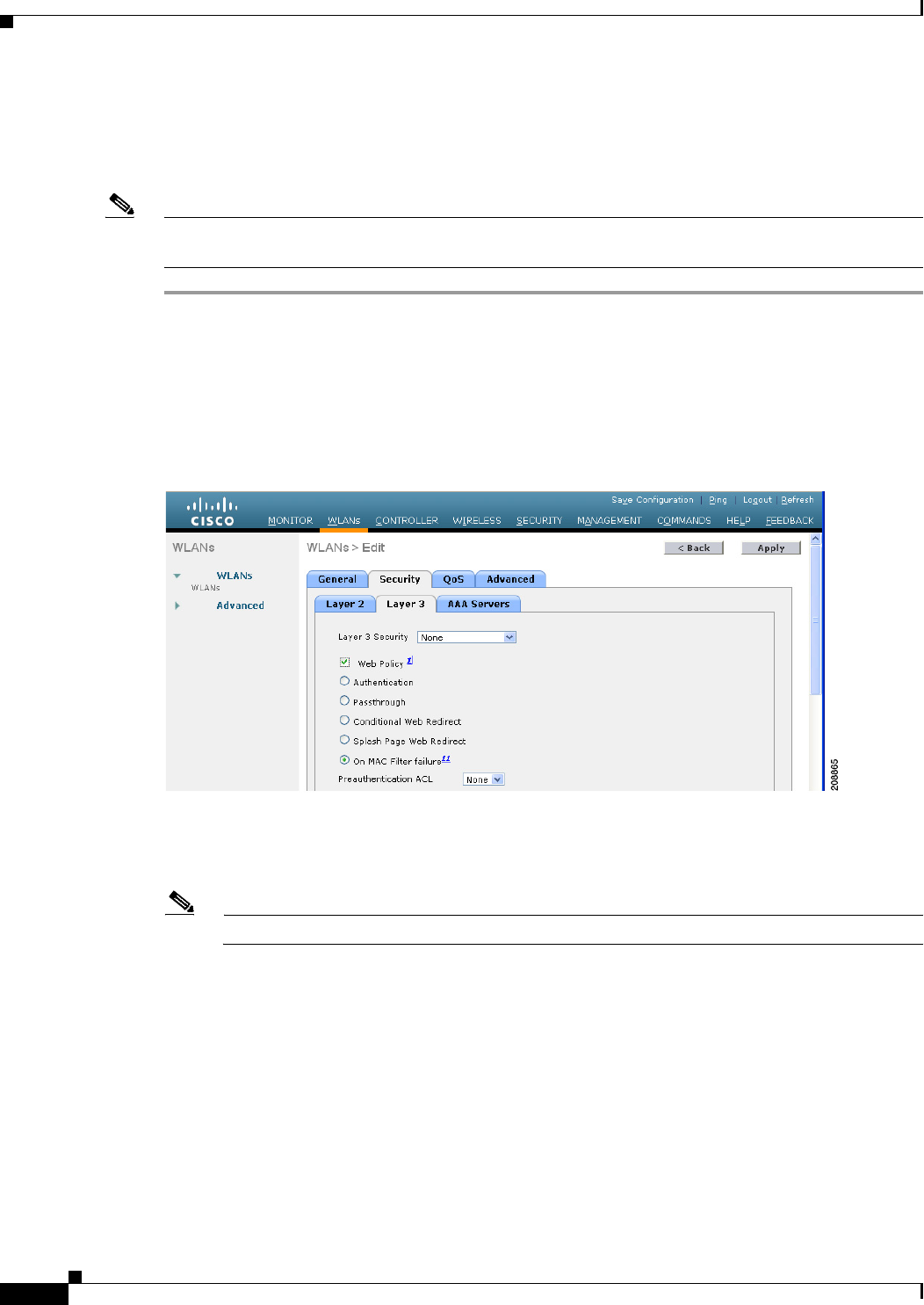
7-36
Cisco Wireless LAN Controller Configuration Guide
OL-21524-02
Chapter 7 Configuring WLANs
Configuring DHCP
Using the GUI to Configure a Fallback Policy with MAC Filtering and Web Authentication
To configure a fallback policy with MAC filtering and web authentication on a WLAN using the
controller GUI, follow these steps:
Note Before configuring a fallback policy, you must have MAC filtering enabled. To know more about how
to enable MAC filtering, see the “Configuring MAC Filtering for WLANs” section on page 7-17.
Step 1 Choose WLANs to open the WLANs page.
Step 2 Click the ID number of the WLAN for which you want to configure the fallback policy for web
authentication. The WLANs > Edit page appears.
Step 3 Choose the Security and Layer 3 tabs to open the WLANs > Edit (Security > Layer 3) page (see
Figure 7-13).
Figure 7-13 WLANs > Edit (Security > Layer 3) Page
Step 4 From the Layer 3 Security drop-down list, choose None.
Step 5 Select the Web Policy check box.
Note The controller forwards DNS traffic to and from wireless clients prior to authentication.
The following options are displayed:
• Authentication
• Passthrough
• Conditional Web Redirect
• Splash Page Web Redirect
• On MAC Filter Failure
Step 6 Click On MAC Filter Failure.
Step 7 Click Apply to commit your changes.

7-37
Cisco Wireless LAN Controller Configuration Guide
OL-21524-02
Chapter 7 Configuring WLANs
Configuring DHCP
Step 8 Click Save Configuration to save your settings.
Using the CLI to Configure a Fallback Policy with MAC Filtering and Web Authentication
To configure a fallback policy with MAC filtering and web authentication on a WLAN using the
controller CLI, follow these steps:
Note Before configuring a fallback policy , you must have MAC filtering enabled. To know more about how
to enable MAC filtering, see the “Configuring MAC Filtering for WLANs” section on page 7-17
Step 1 Enable or disable web authentication on a particular WLAN by entering this command:
config wlan security web-auth on-macfilter-failure wlan-id
Step 2 See the web authentication status by entering this command:
show wlan wlan_id
FT Over-The-Ds mode.............................. Enabled
CKIP ......................................... Disabled
IP Security................................... Disabled
IP Security Passthru.......................... Disabled
Web Based Authentication...................... Enabled-On-MACFilter-Failure
ACL............................................. Unconfigured
Web Authentication server precedence:
1............................................... local
2............................................... radius
3............................................... ldap
Assigning a QoS Profile to a WLAN
Cisco UWN solution WLANs support four levels of QoS: Platinum/Voice, Gold/Video, Silver/Best
Effort (default), and Bronze/Background. You can configure the voice traffic WLAN to use Platinum
QoS, assign the low-bandwidth WLAN to use Bronze QoS, and assign all other traffic between the
remaining QoS levels.
The WLAN QoS level defines a specific 802.11e user priority (UP) for over-the-air traffic. This UP is
used to derive the over-the-wire priorities for non-WMM traffic, and it also acts as the ceiling when
managing WMM traffic with various levels of priorities. The access point uses this QoS-profile-specific
UP in accordance with the values in Table 7-2 to derive the IP DSCP value that is visible on the wired
LAN.
Ta b l e 7-2 Access Point QoS Translation Values
AVVID Traffic Type AVVID IP DSCP QoS Profile AVVID 802.1p IEEE 802.11e UP
Network control 56 (CS7) Platinum 7 7
Inter-network control
(CAPWAP control,
802.11 management)
48 (CS6) Platinum 6 7
Vo i c e 46 (EF) Platinum 5 6

7-38
Cisco Wireless LAN Controller Configuration Guide
OL-21524-02
Chapter 7 Configuring WLANs
Configuring DHCP
You can assign a QoS profile to a WLAN using the controller GUI or CLI.
Using the GUI to Assign a QoS Profile to a WLAN
To assign a QoS profile to a WLAN using the controller GUI, follow these steps:
Step 1 If you have not already done so, configure one or more QoS profiles using the instructions in the “Using
the GUI to Configure QoS Profiles” section on page 4-68.
Step 2 Choose WLANs to open the WLANs page.
Step 3 Click the ID number of the WLAN to which you want to assign a QoS profile.
Step 4 When the WLANs > Edit page appears, choose the QoS tab.
Step 5 From the Quality of Service (QoS) drop-down list, choose one of the following:
• Platinum (voice)
• Gold (video)
• Silver (best effort)
• Bronze (background)
Note Silver (best effort) is the default value.
Step 6 Click Apply to commit your changes.
Step 7 Click Save Configuration to save your changes.
Using the CLI to Assign a QoS Profile to a WLAN
To assign a QoS profile to a WLAN using the controller CLI, follow these steps:
Step 1 If you have not already done so, configure one or more QoS profiles using the instructions in the “Using
the CLI to Configure QoS Profiles” section on page 4-70.
Step 2 Assign a QoS profile to a WLAN by entering this command:
config wlan qos wlan_id {bronze | silver | gold | platinum}
Silver is the default value.
Interactive video 34 (AF41) Gold 4 5
Mission critical 26 (AF31) Gold 3 4
Transactional 18 (AF21) Silver 2 3
Bulk data 10 (AF11) Bronze 1 2
Best effort 0 (BE) Silver 0 0
Scavenger 2Bronze 0 1
Table 7-2 Access Point QoS Translation Values (continued)
AVVID Traffic Type AVVID IP DSCP QoS Profile AVVID 802.1p IEEE 802.11e UP

7-39
Cisco Wireless LAN Controller Configuration Guide
OL-21524-02
Chapter 7 Configuring WLANs
Configuring DHCP
Step 3 Save your changes by entering this command:
save config
Step 4 Verify that you have properly assigned the QoS profile to the WLAN by entering this command:
show wlan wlan_id
Information similar to the following appears:
WLAN Identifier.................................. 1
Profile Name..................................... test
Network Name (SSID).............................. test
Status........................................... Enabled
MAC Filtering.................................... Disabled
Broadcast SSID................................... Enabled
AAA Policy Override.............................. Disabled
Number of Active Clients......................... 0
Exclusionlist.................................... Disabled
Session Timeout.................................. 0
Interface........................................ management
WLAN ACL......................................... unconfigured
DHCP Server...................................... 1.100.163.24
DHCP Address Assignment Required................. Disabled
Quality of Service............................... Silver (best effort)
WMM.............................................. Disabled
...
Configuring QoS Enhanced BSS
The QoS Enhanced Basis Service Set (QBSS) information element (IE) enables the access points to
communicate their channel usage to wireless devices. Because access points with high channel usage
might not be able to handle real-time traffic effectively, the 7921 or 7920 phone uses the QBSS value to
determine if they should associate to another access point. You can enable QBSS in these two modes:
• Wi-Fi Multimedia (WMM) mode, which supports devices that meet the 802.11E QBSS standard
(such as Cisco 7921 IP Phones)
• 7920 support mode, which supports Cisco 7920 IP Phones on your 802.11b/g network
The 7920 support mode has two options:
–
Support for 7920 phones that require call admission control (CAC) to be configured on and
advertised by the client device (these are typically older 7920 phones)
–
Support for 7920 phones that require CAC to be configured on and advertised by the access
point (these are typically newer 7920 phones)
When access point-controlled CAC is enabled, the access point sends out a Cisco proprietary
CAC Information Element (IE) and does not send out the standard QBSS IE.
Note The OEAP 600 Series access points do not support CAC.
You can use the controller GUI or CLI to configure QBSS. QBSS is disabled by default.

7-40
Cisco Wireless LAN Controller Configuration Guide
OL-21524-02
Chapter 7 Configuring WLANs
Configuring DHCP
Guidelines for Configuring QBSS
Follow these guidelines when configuring QBSS on a WLAN:
• 7920 phones are non-WMM phones with limited CAC functionality. The phones look at the channel
utilization of the access point to which they are associated and compare that to a threshold that is
beaconed by the access point. If the channel utilization is less than the threshold, the 7920 places a
call. In contrast, 7921 phones are full-fledged WMM phones that use traffic specifications (TSPECs)
to gain access to the voice queue before placing a phone call. The 7921 phones work well with
load-based CAC, which uses the percentage of the channel set aside for voice and tries to limit the
calls accordingly.
Because 7921 phones support WMM and 7920 phones do not, capacity and voice quality problems
can arise if you do not properly configure both phones when they are used in a mixed environment.
To enable both 7921 and 7920 phones to co-exist on the same network, make sure that load-based
CAC and 7920 AP CAC are both enabled on the controller and the WMM Policy is set to Allowed.
These settings become particularly important if you have many more 7920 users than 7921 users.
Note See Chapter 4, “Configuring Controller Settings,” for more information and configuration
instructions for load-based CAC.
Additional Guidelines for Using Cisco 7921 and 7920 Wireless IP Phones
Follow these guidelines to use Cisco 7921 and 7920 Wireless IP Phones with controllers:
• Aggressive load balancing must be disabled for each controller. Otherwise, the initial roam attempt
by the phone may fail, causing a disruption in the audio path.
• The Dynamic Transmit Power Control (DTPC) information element (IE) must be enabled using the
config 802.11b dtpc enable command. The DTPC IE is a beacon and probe information element
that allows the access point to broadcast information on its transmit power. The 7921 or 7920 phone
uses this information to automatically adjust its transmit power to the same level as the access point
to which it is associated. In this manner, both devices are transmitting at the same level.
• Both the 7921 and 7920 phones and the controllers support Cisco Centralized Key Management
(CCKM) fast roaming.
• When configuring WEP, there is a difference in nomenclature for the controller and the 7921 or 7920
phone. Configure the controller for 104 bits when using 128-bit WEP for the 7921 or 7920.
• For standalone 7921 phones, load-based CAC must be enabled, and the WMM Policy must be set to
Required on the WLAN.
• The controller supports traffic classification (TCLAS) coming from 7921 phones using firmware
version 1.1.1. This feature ensures proper classification of voice streams to the 7921 phones.
• When using a 7921 phone with the 802.11a radio of a 1242 series access point, set the 24-Mbps data
rate to Supported and choose a lower Mandatory data rate (such as 12 Mbps). Otherwise, the phone
might experience poor voice quality.
Using the GUI to Configure QBSS
To configure QBSS using the controller GUI, follow these steps:
Step 1 Choose WLANs to open the WLANs page.
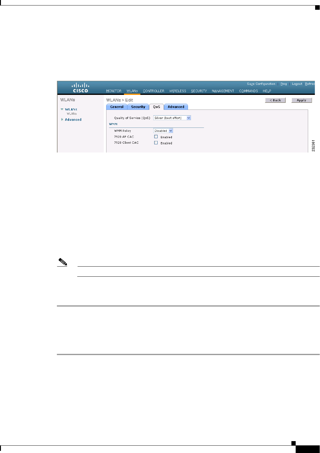
7-41
Cisco Wireless LAN Controller Configuration Guide
OL-21524-02
Chapter 7 Configuring WLANs
Configuring DHCP
Step 2 Click the ID number of the WLAN for which you want to configure WMM mode.
Step 3 When the WLANs > Edit page appears, choose the QoS tab to open the WLANs > Edit (Qos) page (see
Figure 7-14).
Figure 7-14 WLANs > Edit (QoS) Page
Step 4 From the WMM Policy drop-down list, choose one of the following options, depending on whether you
want to enable WMM mode for 7921 phones and other devices that meet the WMM standard:
• Disabled—Disables WMM on the WLAN. This is the default value.
• Allowed—Allows client devices to use WMM on the WLAN.
• Required—Requires client devices to use WMM. Devices that do not support WMM cannot join
the WLAN.
Step 5 Select the 7920 AP CAC check box if you want to enable 7920 support mode for phones that require
access point-controlled CAC. The default value is unselected.
Step 6 Select the 7920 Client CAC check box if you want to enable 7920 support mode for phones that require
client-controlled CAC. The default value is unselected.
Note You cannot enable both WMM mode and client-controlled CAC mode on the same WLAN.
Step 7 Click Apply to commit your changes.
Step 8 Click Save Configuration to save your changes.
Using the CLI to Configure QBSS
To configure QBSS using the controller CLI, follow these steps:
Step 1 Determine the ID number of the WLAN to which you want to add QBSS support by entering this
command:
show wlan summary
Step 2 Disable the WLAN by entering this command:
config wlan disable wlan_id
Step 3 Configure WMM mode for 7921 phones and other devices that meet the WMM standard by entering this
command:

7-42
Cisco Wireless LAN Controller Configuration Guide
OL-21524-02
Chapter 7 Configuring WLANs
Configuring DHCP
config wlan wmm {disabled | allowed | required} wlan_id
where
• disabled disables WMM mode on the WLAN.
• allowed allows client devices to use WMM on the WLAN.
• required requires client devices to use WMM. Devices that do not support WMM cannot join the
WLAN.
Step 4 Enable or disable 7920 support mode for phones that require client-controlled CAC by entering this
command:
config wlan 7920-support client-cac-limit {enable | disable} wlan_id
Note You cannot enable both WMM mode and client-controlled CAC mode on the same WLAN.
Step 5 Enable or disable 7920 support mode for phones that require access point-controlled CAC by entering
this command:
config wlan 7920-support ap-cac-limit {enable | disable} wlan_id
Step 6 Reenable the WLAN by entering this command:
config wlan enable wlan_id
Step 7 Save your changes by entering this command:
save config
Step 8 Verify that the WLAN is enabled and the Dot11-Phone Mode (7920) text box is configured for compact
mode by entering this command:
show wlan wlan_id
Configuring Media Session Snooping and Reporting
Controller software release 6.0 or later releases support Voice over IP (VoIP) Media Session Aware
(MSA) snooping and reporting. This feature enables access points to detect the establishment,
termination, and failure of Session Initiation Protocol (SIP) voice calls and then report them to the
controller and WCS. VoIP snooping and reporting can be enabled or disabled for each WLAN.
When VoIP MSA snooping is enabled, the access point radios that advertise this WLAN look for SIP
voice packets that comply with SIP RFC 3261. They do not look for non-RFC 3261-compliant SIP voice
packets or Skinny Call Control Protocol (SCCP) voice packets. Any SIP packets destined to or
originating from port number 5060 (the standard SIP signaling port) are considered for further
inspection. The access points track when Wi-Fi Multimedia (WMM) and non-WMM clients are
establishing a call, are already on an active call, or are in the process of ending a call. Upstream packet
classification for both client types occurs at the access point. Downstream packet classification occurs
at the controller for WMM clients and at the access point for non-WMM clients. The access points notify
the controller and WCS of any major call events, such as call establishment, termination, and failure.
The controller provides detailed information for VoIP MSA calls. For failed calls, the controller
generates a trap log with a timestamp and the reason for failure (in the GUI) and an error code (in the
CLI) to aid in troubleshooting. For successful calls, the controller shows the number and duration of calls
for usage tracking purposes. WCS displays failed VoIP call information in the Events page.
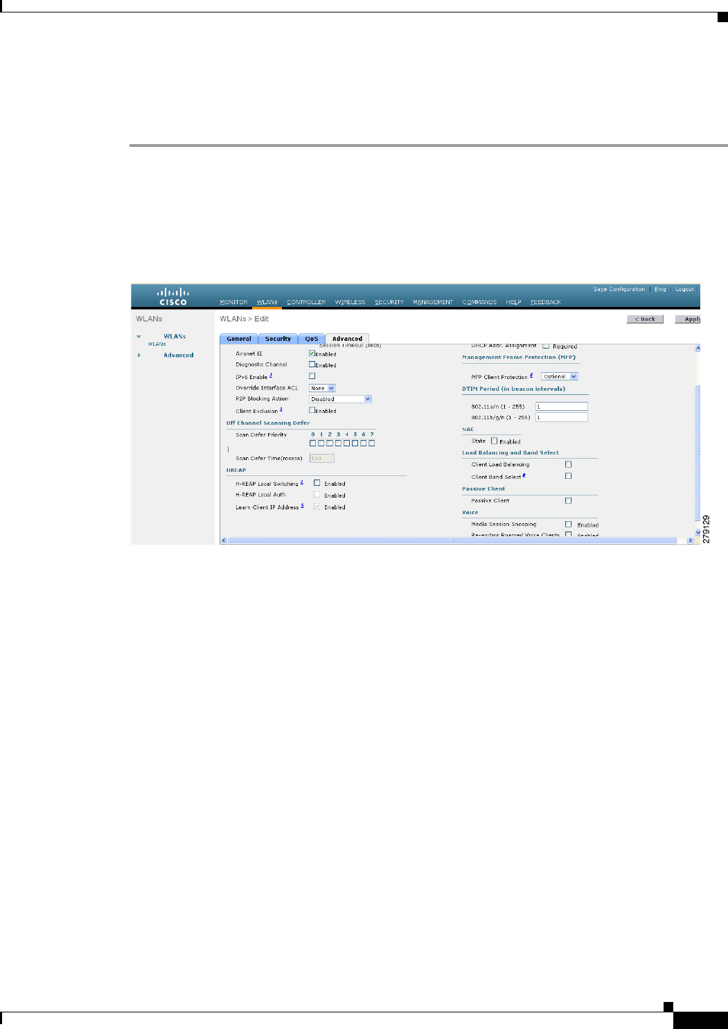
7-43
Cisco Wireless LAN Controller Configuration Guide
OL-21524-02
Chapter 7 Configuring WLANs
Configuring DHCP
Using the GUI to Configure Media Session Snooping
To configure media session snooping using the controller GUI, follow these steps:
Step 1 Choose WLANs to open the WLANs page.
Step 2 Click the ID number of the WLAN for which you want to configure media session snooping.
Step 3 When the WLANs > Edit page appears, choose the Advanced tab to open the WLANs > Edit (Advanced)
page (see Figure 7-15).
Figure 7-15 WLANs > Edit (Advanced) Page
Step 4 Under the Voice, select the Media Session Snooping check box to enable media session snooping or
unselect it to disable this feature. The default value is unselected.
Step 5 Click Apply to commit your changes.
Step 6 Click Save Configuration to save your changes.
Step 7 See the VoIP statistics for your access point radios as follows:
a. Choose Monitor > Access Points > Radios > 802.11a/n or 802.11b/g/n to open the 802.11a/n (or
802.11b/g/n) Radios page.
b. Scroll to the right and click the Detail link for the access point for which you want to view VoIP
statistics. The Radio > Statistics page appears (see Figure 7-16).
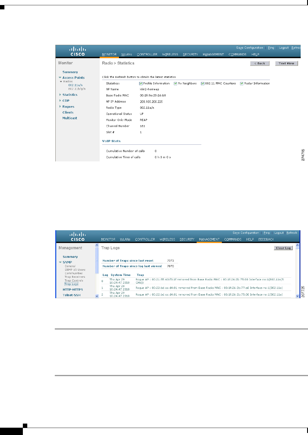
7-44
Cisco Wireless LAN Controller Configuration Guide
OL-21524-02
Chapter 7 Configuring WLANs
Configuring DHCP
Figure 7-16 Radio > Statistics Page
The VoIP Stats section shows the cumulative number and length of voice calls for this access point radio.
Entries are added automatically when voice calls are successfully placed and deleted when the access
point disassociates from the controller.
Step 8 Choose Management > SNMP > Trap Logs to see the traps generated for failed calls. The Trap Logs
page appears (Figure 7-17).
Figure 7-17 Trap Logs Page
For example, log 0 in Figure 7-17 shows that a call failed. The log provides the date and time of the call,
a description of the failure, and the reason why the failure occurred.
Using the CLI to Configure Media Session Snooping
To configure VoIP snooping using the controller CLI, follow these steps:
Step 1 Enable or disable VoIP snooping for a particular WLAN by entering this command:
config wlan call-snoop {enable | disable} wlan_id
Step 2 Save your changes by entering this command:

7-45
Cisco Wireless LAN Controller Configuration Guide
OL-21524-02
Chapter 7 Configuring WLANs
Configuring DHCP
save config
Step 3 See the status of media session snooping on a particular WLAN by entering this command:
show wlan wlan_id
Information similar to the following appears:
WLAN Identifier.................................. 1
Profile Name..................................... wpa2-psk
Network Name (SSID).............................. wpa2-psk
Status........................................... Enabled
...
H-REAP Local Switching........................ Disabled
H-REAP Learn IP Address....................... Enabled
Infrastructure MFP protection.............. Enabled (Global Infrastructure MFP
Disabled)
Client MFP.................................... Optional
Tkip MIC Countermeasure Hold-down Timer....... 60
Call Snooping.................................. Enabled
Step 4 See the call information for an MSA client when media session snooping is enabled and the call is active
by entering this command:
show call-control client callInfo client_MAC_address
Information similar to the following appears:
Uplink IP/port...................................... 192.11.1.71 / 23870
Downlonk IP/port.................................... 192.12.1.47 / 2070
UP.................................................. 6
Calling Party....................................... sip:1054
Called Party........................................ sip:1000
Call ID............................................. 58635b00-850161b7-14853-1501a8
Number of calls for given client is.............. 1
Step 5 See the metrics for successful calls or the traps generated for failed calls by entering this command:
show call-control ap {802.11a | 802.11b} Cisco_AP {metrics | traps}
Information similar to the following appears when you enter show call-control ap {802.11a | 802.11b}
Cisco_AP metrics:
Total Call Duration in Seconds................... 120
Number of Calls.................................. 10
Information similar to the following appears when you enter show call-control ap {802.11a | 802.11b}
Cisco_AP traps:
Number of traps sent in one min.................. 2
Last SIP error code.............................. 404
Last sent trap timestamp...................... Jun 20 10:05:06
To aid in troubleshooting, the output of this command shows an error code for any failed calls. Table 7-3
explains the possible error codes for failed calls.
Ta b l e 7-3 Error Codes for Failed VoIP Calls
Error Code Integer Description
1unknown Unknown error.
400 badRequest The request could not be understood because of
malformed syntax.
401 unauthorized The request requires user authentication.

7-46
Cisco Wireless LAN Controller Configuration Guide
OL-21524-02
Chapter 7 Configuring WLANs
Configuring DHCP
402 paymentRequired Reserved for future use.
403 forbidden The server understood the request but refuses to fulfill it.
404 notFound The server has information that the user does not exist at
the domain specified in the Request-URI.
405 methodNotallowed The method specified in the Request-Line is understood
but not allowed for the address identified by the
Request-URI.
406 notAcceptabl The resource identified by the request is only capable of
generating response entities with content characteristics
that are not acceptable according to the Accept header
text box sent in the request.
407 proxyAuthenticationRequired The client must first authenticate with the proxy.
408 requestTimeout The server could not produce a response within a suitable
amount of time, if it could not determine the location of
the user in time.
409 conflict The request could not be completed due to a conflict with
the current state of the resource.
410 gone The requested resource is no longer available at the
server, and no forwarding address is known.
411 lengthRequired The server is refusing to process a request because the
request entity-body is larger than the server is willing or
able to process.
413 requestEntityTooLarge The server is refusing to process a request because the
request entity-body is larger than the server is willing or
able to process.
414 requestURITooLarge The server is refusing to service the request because the
Request-URI is longer than the server is willing to
interpret.
415 unsupportedMediaType The server is refusing to service the request because the
message body of the request is in a format not supported
by the server for the requested method.
420 badExtension The server did not understand the protocol extension
specified in a Proxy-Require or Require header text box.
480 temporarilyNotAvailable The callee’s end system was contacted successfully, but
the callee is currently unavailable.
481 callLegDoesNotExist The UAS received a request that does not match any
existing dialog or transaction.
482 loopDetected The server has detected a loop.
483 tooManyHops The server received a request that contains a
Max-Forwards header text box with the value zero.
484 addressIncomplete The server received a request with a Request-URI that
was incomplete.
Table 7-3 Error Codes for Failed VoIP Calls (continued)
Error Code Integer Description

7-47
Cisco Wireless LAN Controller Configuration Guide
OL-21524-02
Chapter 7 Configuring WLANs
Configuring DHCP
Note If you experience any problems with media session snooping, enter the debug call-control {all | event}
{enable | disable} command to debug all media session snooping messages or events.
Configuring Reanchoring of Roaming Voice Clients
You can allow voice clients to get anchored on the best suited and nearest available controller, which is
useful when intercontroller roaming occurs. By using this feature, you can avoid the use of tunnels to
carry traffic between the foreign controller and the anchor controller and remove unnecessary traffic
from the network.
485 ambiguous The Request-URI was ambiguous.
486 busy The callee’s end system was contacted successfully, but
the callee is currently not willing or able to take
additional calls at this end system.
500 internalServerError The server encountered an unexpected condition that
prevented it from fulfilling the request.
501 notImplemented The server does not support the functionality required to
fulfill the request.
502 badGateway The server, while acting as a gateway or proxy, received
an invalid response from the downstream server it
accessed in attempting to fulfill the request.
503 serviceUnavailable The server is temporarily unable to process the request
because of a temporary overloading or maintenance of
the server.
504 serverTimeout The server did not receive a timely response from an
external server it accessed in attempting to process the
request.
505 versionNotSupported The server does not support or refuses to support the SIP
protocol version that was used in the request.
600 busyEverywhere The callee’s end system was contacted successfully, but
the callee is busy or does not want to take the call at this
time.
603 decline The callee’s machine was contacted successfully, but the
user does not want to or cannot participate.
604 doesNotExistAnywhere The server has information that the user indicated in the
Request-URI does not exist anywhere.
606 notAcceptable The user’s agent was contacted successfully, but some
aspects of the session description (such as the requested
media, bandwidth, or addressing style) were not
acceptable.
Table 7-3 Error Codes for Failed VoIP Calls (continued)
Error Code Integer Description
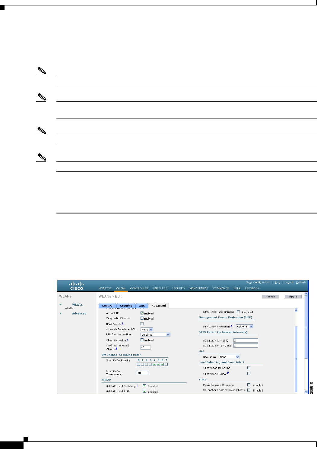
7-48
Cisco Wireless LAN Controller Configuration Guide
OL-21524-02
Chapter 7 Configuring WLANs
Configuring DHCP
The ongoing call during roaming is not affected and can continue without any problem. The traffic passes
through proper tunnels that are established between the foreign controller and the anchor controller.
Disassociation occurs only after the call ends , and then the client then gets reassociated to a new
controller.
Note The ongoing data session might be affected due to disassociation and then reassociation.
Note This feature is supported for TSPEC-based calls and non-TSPEC SIP-based calls only when you enable
the admission control.
Note You can reanchor roaming of voice clients for each WLAN.
Note This feature is not recommended for use on Cisco 792x phones.
Using the GUI to Configure Reanchoring of Roaming Voice Clients
To configure reanchoring of roaming clients using the controller GUI, follow these steps:
Step 1 Choose WLANs to open the WLANs page.
Step 2 Click the ID number of the WLAN for which you want to configure reanchoring of roaming voice
clients.
Step 3 When the WLANs > Edit page appears, choose the Advanced tab to open the WLANs > Edit (Advanced)
page (see Figure 7-18).
Figure 7-18 WLANs > Edit (Advanced) Page
Step 4 In the Voice area select the Re-anchor Roamed Clients check box.
Step 5 Click Apply to commit your changes.

7-49
Cisco Wireless LAN Controller Configuration Guide
OL-21524-02
Chapter 7 Configuring WLANs
Configuring DHCP
Step 6 Click Save Configuration to save your changes.
Using the CLI to Configure Reanchoring of Roaming Voice Clients
To configure reanchoring of roaming voice clients using the controller CLI, follow these steps:
Step 1 Enable or disable reanchoring of roaming voice clients for a particular WLAN by entering this
command:
config wlan roamed-voice-client re-anchor {enable | disable} wlan id
Step 2 Save your changes by entering this command:
save config
Step 3 See the status of reanchoring roaming voice client on a particular WLAN by entering this command:
show wlan wlan_id
Information similar to the following appears:
WLAN Identifier.................................. 1
Profile Name..................................... wpa2-psk
Network Name (SSID).............................. wpa2-psk
Status........................................... Enabled
...
Call Snooping.................................... Enabled
Roamed Call Re-Anchor Policy..................... Enabled
Band Select...................................... Disabled
Load Balancing................................... Disabled
Step 4 Save your changes by entering this command:
save config
Configuring IPv6 Bridging
Internet Protocol version 6 (IPv6) is the next-generation network layer Internet protocol intended to
replace version 4 (IPv4) in the TCP/IP suite of protocols. This new version increases Internet global
address space to accommodate users and applications that require unique global IP addresses. IPv6
incorporates 128-bit source and destination addresses, providing significantly more addresses than the
32-bit IPv4 addresses. Follow the instructions in this section to configure a WLAN for IPv6 bridging
using either the controller GUI or CLI.
Guidelines for Using IPv6 Bridging
Follow these guidelines when using IPv6 bridging:
• To use IPv6 bridging, multicast must be enabled on the controller.
• Hybrid-REAP with central switching is supported for use with IPv6 bridging. Hybrid-REAP with
local switching is not supported.
• Auto-anchor mobility is not supported for use with IPv6 bridging.

7-50
Cisco Wireless LAN Controller Configuration Guide
OL-21524-02
Chapter 7 Configuring WLANs
Configuring DHCP
• If symmetric mobility tunneling is enabled, all IPv4 traffic is bidirectionally tunneled to and from
the client, but the IPv6 client traffic is bridged locally.
• Clients must support IPv6 with either static stateless autoconfiguration (such as Windows XP
clients) or stateful DHCPv6 IP addressing (such as Windows Vista clients).
Note Currently, DHCPv6 is supported for use only with Windows Vista clients. For these clients,
you must manually renew the DHCPv6 IP address after the client changes VLANs.
Note Dynamic VLAN function on IPV6 bridging environment is not supported on the Controller
software release 6.0 and 7.0.
• For stateful DHCPv6 IP addressing to operate properly, you need a switch or router that supports
the DHCP for IPv6 feature (such as the Catalyst 3750 switch) and is configured to act like a DHCPv6
server, or you need a dedicated server such as a Windows 2008 server with a built-in DHCPv6 server.
Note To load the SDM IPv6 template in the Catalyst 3750 switch, enter the sdm prefer
dual-ipv4-and-v6 default command and then reset the switch. For more information, see
Catalyst 3750 Switch Configuration Guide for Cisco IOS Release 12.2(46)SE.
• In controller software release 4.2 or later releases, you can enable IPv6 bridging and IPv4 web
authentication on the same WLAN, a combination that previously was not supported. The controller
bridges IPv6 traffic from all clients on the WLAN while IPv4 traffic goes through the normal web
authentication process. The controller begins bridging IPv6 as soon as the client associates and even
before web authentication for IPv4 clients is complete. No other Layer 2 or Layer 3 security policy
configuration is supported on the WLAN when both IPv6 bridging and web authentication are
enabled. Figure 7-19 shows how IPv6 bridging and IPv4 web authentication can be used on the same
WLAN.
• In controller software release 6.0 or later releases, all Layer 2 security policies are supported and
can be configured when you enable IPv6 bridging on a WLAN.
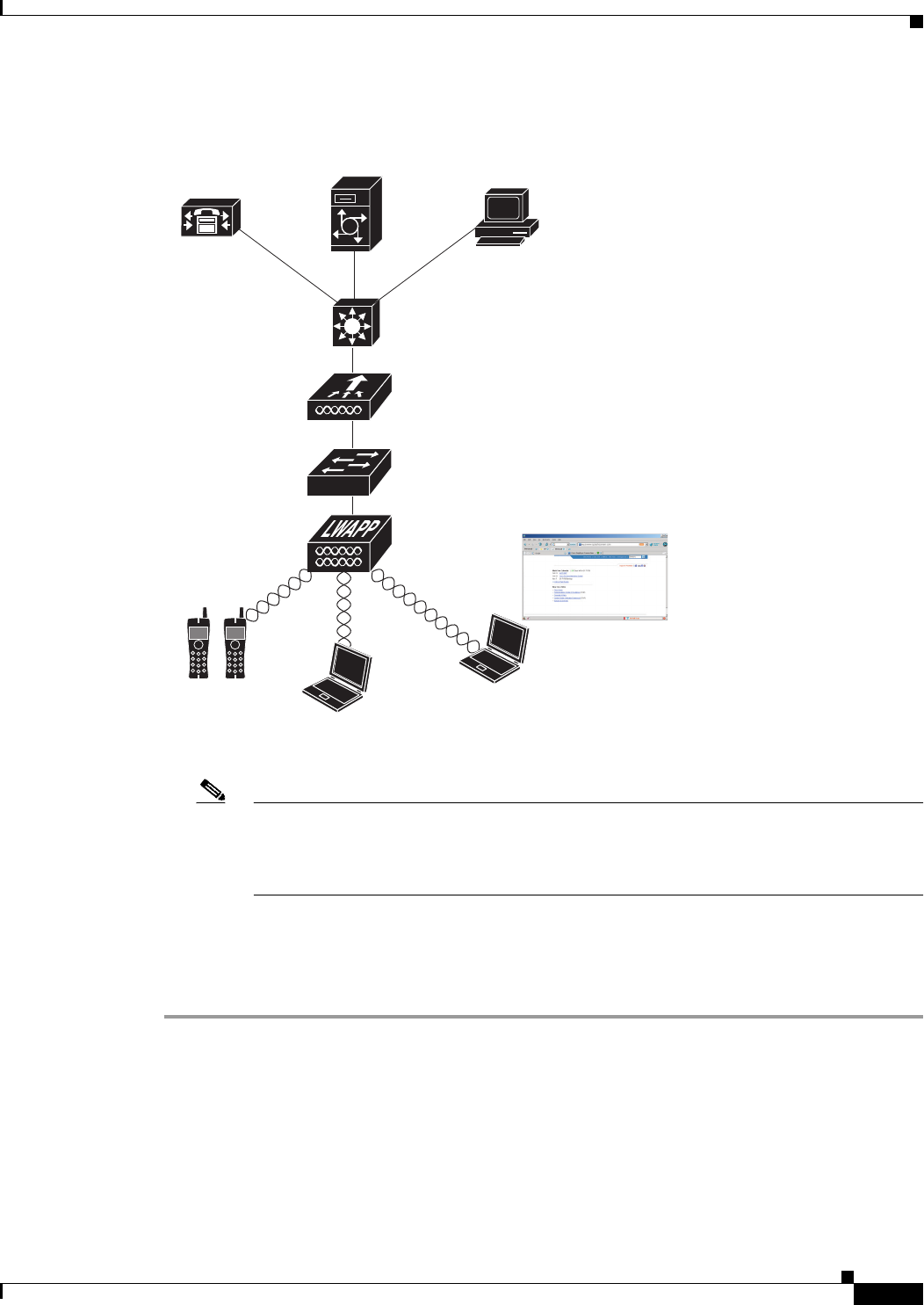
7-51
Cisco Wireless LAN Controller Configuration Guide
OL-21524-02
Chapter 7 Configuring WLANs
Configuring DHCP
Figure 7-19 IPv6 Bridging and IPv4 Web Authentication
Note The Security Policy Completed text box in both the controller GUI and CLI shows “No for
IPv4 (bridging allowed for IPv6)” until web authentication is completed. You can view this
text box from the Clients > Detail page on the GUI or from the show client detail CLI
command.
Using the GUI to Configure IPv6 Bridging
To configure a WLAN for IPv6 bridging using the controller GUI, follow these steps:
Step 1 Choose WLANs to open the WLANs page.
Step 2 Click the ID number of the desired WLAN to open the WLANs > Edit page.
Step 3 Choose the Advanced tab to open the WLANs > Edit (Advanced tab) page (see Figure 7-20).
WCS
Splash page
Cisco Unified
Unity server
Cisco Unified
CallManager
Voice WLAN
Data WLAN
IPv6 Client - Traffic is bridged
Data WLAN
IPv4 Client - Web authentication
232299
Si
U
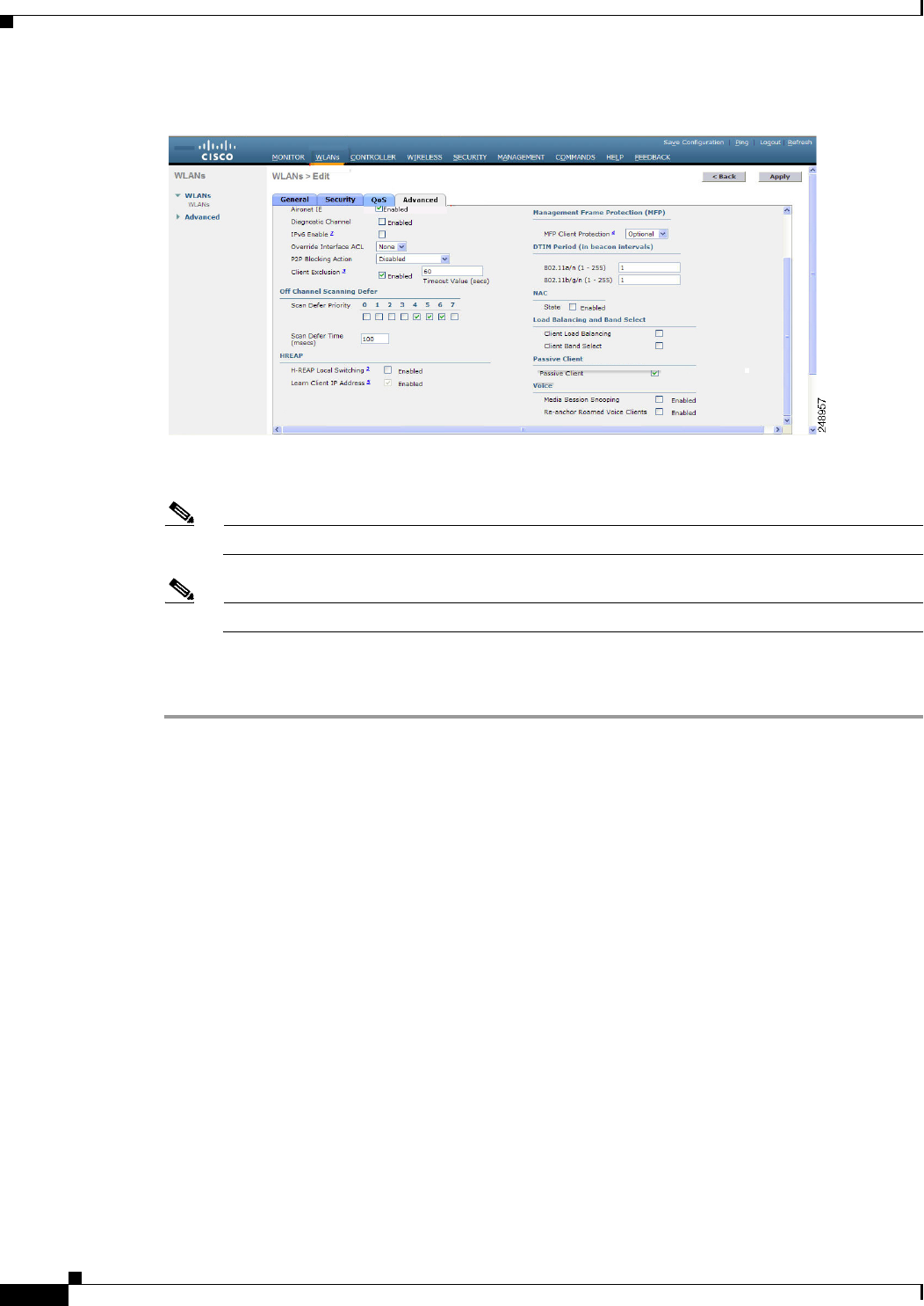
7-52
Cisco Wireless LAN Controller Configuration Guide
OL-21524-02
Chapter 7 Configuring WLANs
Configuring DHCP
Figure 7-20 WLANs > Edit (Advanced) Page
Step 4 Select the IPv6 Enable check box if you want to enable clients that connect to this WLAN to accept
IPv6 packets. Otherwise, leave the check box unselected, which is the default value.
Note If you disable (or uncheck) the IPv6 check box, IPv6 will only be allowed after authentication.
Note Enabling IPv6 means that the controller can pass IPv6 traffic without client authentication.
Step 5 Click Apply to commit your changes.
Step 6 Click Save Configuration to save your changes.
Using the CLI to Configure IPv6 Bridging
Configure a WLAN for IPv6 bridging using the controller CLI by entering this command:
config wlan IPv6support {enable | disable} wlan_id
The default value is disabled.
Configuring Cisco Client Extensions
Cisco Client Extensions (CCX) software is licensed to manufacturers and vendors of third-party client
devices. The CCX code resident on these clients enables them to communicate wirelessly with Cisco
access points and to support Cisco features that other client devices do not, including those features
related to increased security, enhanced performance, fast roaming, and superior power management.
The 4.2 or later releases of controller software support CCX versions 1 through 5, which enables
controllers and their access points to communicate wirelessly with third-party client devices that support
CCX. CCX support is enabled automatically for every WLAN on the controller and cannot be disabled.
However, you can configure a specific CCX feature per WLAN. This feature is Aironet information
elements (IEs).

7-53
Cisco Wireless LAN Controller Configuration Guide
OL-21524-02
Chapter 7 Configuring WLANs
Configuring DHCP
If Aironet IE support is enabled, the access point sends an Aironet IE 0x85 (which contains the access
point name, load, number of associated clients, and so on) in the beacon and probe responses of this
WLAN, and the controller sends Aironet IEs 0x85 and 0x95 (which contains the management IP address
of the controller and the IP address of the access point) in the reassociation response if it receives Aironet
IE 0x85 in the reassociation request.
Follow the instructions in this section to configure a WLAN for the CCX Aironet IE feature and to see
the CCX version supported by specific client devices using either the GUI or the CLI.
Note CCX is not supported on Cisco OEAP 600 access points and all elements related to CCX are not
supported.
Note Cisco OEAP 600 do not support Aeronet IEs.
Using the GUI to Configure CCX Aironet IEs
To configure a WLAN for CCX Aironet IEs using the controller GUI, follow these steps:
Step 1 Choose WLANs to open the WLANs page.
Step 2 Click the ID number of the desired WLAN to open the WLANs > Edit page.
Step 3 Choose the Advanced tab to open the WLANs > Edit (Advanced tab) page (see Figure 7-20).
Step 4 Select the Aironet IE check box if you want to enable support for Aironet IEs for this WLAN.
Otherwise, unselect this check box. The default value is enabled (or selected).
Step 5 Click Apply to commit your changes.
Step 6 Click Save Configuration to save your changes.
Using the GUI to View a Client’s CCX Version
A client device sends its CCX version in association request packets to the access point. The controller
then stores the client’s CCX version in its database and uses it to limit the features for this client. For
example, if a client supports CCX version 2, the controller does not allow the client to use CCX version
4 features.
To see the CCX version supported by a particular client device using the controller GUI, follow these
steps:
Step 1 Choose Monitor > Clients to open the Clients page.
Step 2 Click the MAC address of the desired client device to open the Clients > Detail page (see Figure 7-21).

7-54
Cisco Wireless LAN Controller Configuration Guide
OL-21524-02
Chapter 7 Configuring WLANs
Configuring DHCP
Figure 7-21 Clients > Detail Page
The CCX Version text box shows the CCX version supported by this client device. Not Supported
appears if the client does not support CCX.
Step 3 Click Back to return to the previous screen.

7-55
Cisco Wireless LAN Controller Configuration Guide
OL-21524-02
Chapter 7 Configuring WLANs
Configuring DHCP
Step 4 Repeat this procedure to view the CCX version supported by any other client devices.
Using the CLI to Configure CCX Aironet IEs
Enable or disable support for Aironet IEs for a particular WLAN using the controller CLI, by entering
this command:
config wlan ccx aironet-ie {enable | disable} wlan_id
The default value is enabled.
Using the CLI to View a Client’s CCX Version
See the CCX version supported by a particular client device using the controller CLI by entering this
command:
show client detail client_mac
Configuring Access Point Groups
After you create up to 512 WLANs on the controller, you can selectively publish them (using access
point groups) to different access points to better manage your wireless network. In a typical deployment,
all users on a WLAN are mapped to a single interface on the controller. Therefore, all users associated
with that WLAN are on the same subnet or VLAN. However, you can choose to distribute the load among
several interfaces or to a group of users based on specific criteria such as individual departments (such as
Marketing) by creating access point groups. Additionally, these access point groups can be configured
in separate VLANs to simplify network administration, as shown in Figure 7-22.
Note The required access control list (ACL) must be defined on the router that serves the VLAN or subnet.
Note Multicast traffic is supported with access point group VLANs. However, if the client roams from one
access point to another, the client might stop receiving multicast traffic, unless IGMP snooping is
enabled.
Note The OEAP 600 Series access point supports a maximum of two WLANs and one remote LAN. If you
have configured more than two WLANs and one remote LAN, you can assign the 600 Series access point
to an AP group. The support for two WLANs and one remote LAN still applies to the AP group If the
600 Series OEAP is in the default group, the WLAN/remote LAN ids must be lower than 8.
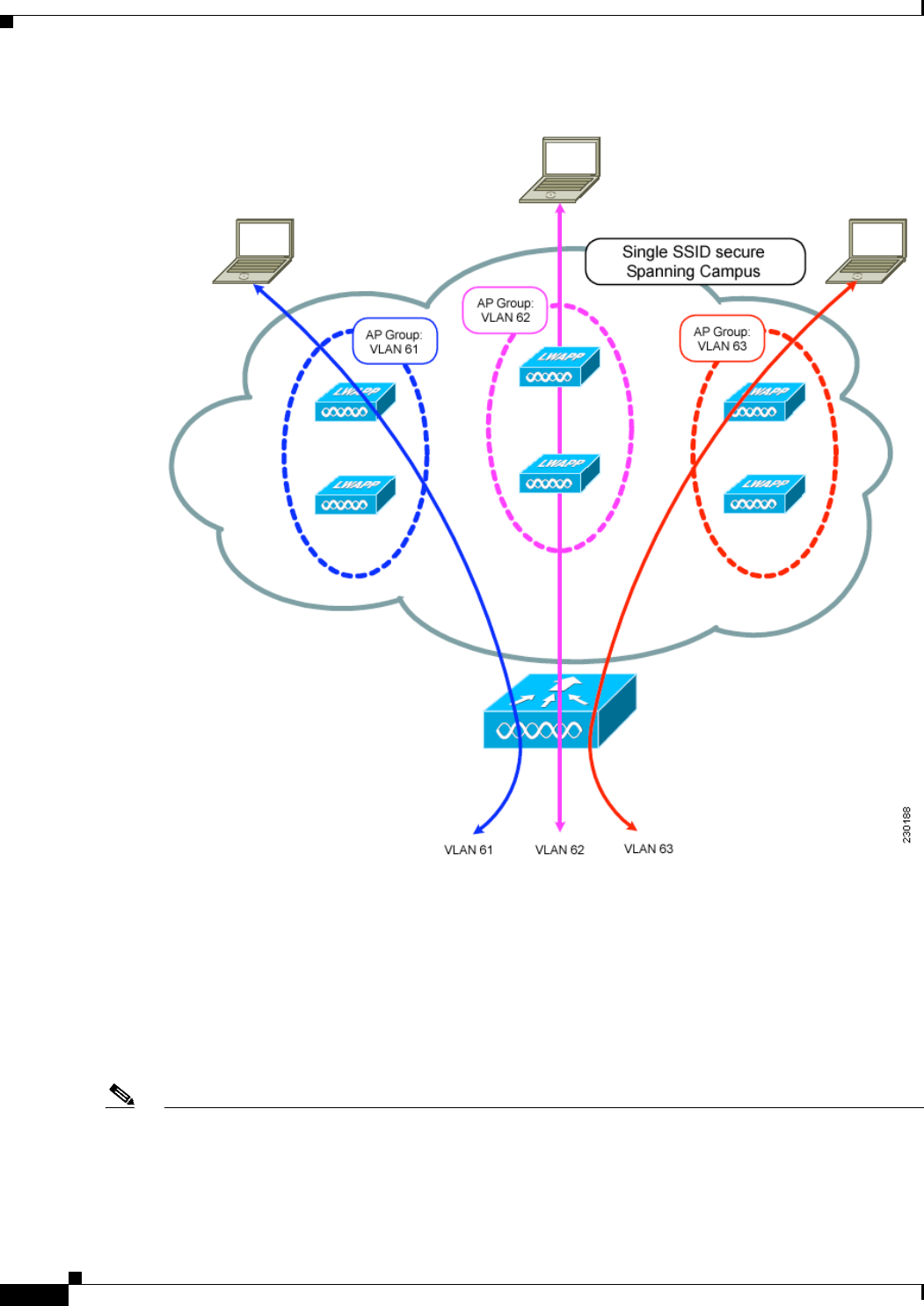
7-56
Cisco Wireless LAN Controller Configuration Guide
OL-21524-02
Chapter 7 Configuring WLANs
Configuring DHCP
Figure 7-22 Access Point Groups
In Figure 7-22, three configured dynamic interfaces are mapped to three different VLANs (VLAN 61,
VLAN 62, and VLAN 63). Three access point groups are defined, and each is a member of a different
VLAN, but all are members of the same SSID. A client within the wireless SSID is assigned an IP
address from the VLAN subnet on which its access point is a member. For example, any user that
associates with an access point that is a member of access point group VLAN 61 is assigned an IP
address from that subnet.
In the example in Figure 7-22, the controller internally treats roaming between access points as a Layer
3 roaming event. In this way, WLAN clients maintain their original IP addresses.
Note Suppose that the interface mapping for a WLAN in the AP group table is the same as the WLAN
interface. If the WLAN interface is changed, the interface mapping for the WLAN in the AP group table
also changes to the new WLAN interface.

7-57
Cisco Wireless LAN Controller Configuration Guide
OL-21524-02
Chapter 7 Configuring WLANs
Configuring DHCP
Suppose that the interface mapping for a WLAN in the AP group table is different from the one defined
for the WLAN. If the WLAN interface is changed, then the interface mapping for the WLAN in the AP
group table does not change to the new WLAN interface.
Note A controller with OfficeExtend access points in an access point group publishes upto 15 WLANs to each
connected OfficeExtend access point because it reserves one WLAN for the personal SSID.
To configure access point groups, follow these steps:
1. Configure the appropriate dynamic interfaces and map them to the desired VLANs.
For example, to implement the network in Figure 7-22, create dynamic interfaces for VLANs 61,
62, and 63 on the controller. See Chapter 3, “Configuring Ports and Interfaces,” for information on
how to configure dynamic interfaces.
2. Create the access point groups. See the “Creating Access Point Groups” section on page 7-57.
3. Assign access points to the appropriate access point groups. See the “Creating Access Point Groups”
section on page 7-57.
Creating Access Point Groups
After all access points have joined the controller, you can create access point groups and assign up to 16
WLANs to each group. Each access point advertises only the enabled WLANs that belong to its access
point group. The access point does not advertise disabled WLANs in its access point group or WLANs
that belong to another group.
You can create up to 50 access point groups for Cisco 2100 Series Controller and controller network
modules; up to 300 access point groups for Cisco 4400 Series Controllers, Cisco WiSM, and 3750G
wireless LAN controller switch; and up to 500 access point groups for Cisco 5500 Series Controllers.
Note All OfficeExtend access points should be in the same access point group, and that group should contain
no more than 15 WLANs. A controller with OfficeExtend access points in an access point group
publishes only up to 15 WLANs to each connected OfficeExtend access point because it reserves one
WLAN for the personal SSID.
Note If you clear the configuration on the controller, all of the access point groups disappear except for the
default access point group “default-group,” which is created automatically.
Using the GUI to Create Access Point Groups
To create an access point group using the controller GUI, follow these steps:
Step 1 Choose WLANs > Advanced > AP Groups to open the AP Groups page (see Figure 7-23).

7-58
Cisco Wireless LAN Controller Configuration Guide
OL-21524-02
Chapter 7 Configuring WLANs
Configuring DHCP
Figure 7-23 AP Groups Page
This page lists all the access point groups currently created on the controller. By default, all access points
belong to the default access point group “default-group,” unless you assign them to other access point
groups.
Note When you upgrade to controller software release 5.2 or later releases, the controller creates the
default-group access point group and automatically populates it with the first 16 WLANs
(WLANs with IDs 1 through 16, or fewer if 16 WLANs are not configured). This default group
cannot be modified (you cannot add WLANs to it nor delete WLANs from it). It is dynamically
updated whenever the first 16 WLANs are added or deleted. If an access point does not belong
to an access point group, it is assigned to the default group and uses the WLANs in that group.
If an access point joins the controller with an undefined access point group name, the access
point keeps its group name but uses the WLANs in the default-group access point group.
Step 2 Click Add Group to create a new access point group. The Add New AP Group section appears at the
top of the page.
Step 3 In the AP Group Name text box, enter the group’s name.
Step 4 In the Description text box, enter the group’s description.
Step 5 Click Add. The newly created access point group appears in the list of access point groups on the AP
Groups page.
Note If you ever want to delete this group, hover your cursor over the blue drop-down arrow for the
group and choose Remove. An error message appears if you try to delete an access point group
that is used by at least one access point. Before deleting an access point group in controller
software release 6.0 or later releases, move all access points in the group to another group. The
access points are not moved to the default-group access point group as in previous releases.
Step 6 Click the name of the group to edit this new group. The AP Groups > Edit (General) page appears (see
Figure 7-24).
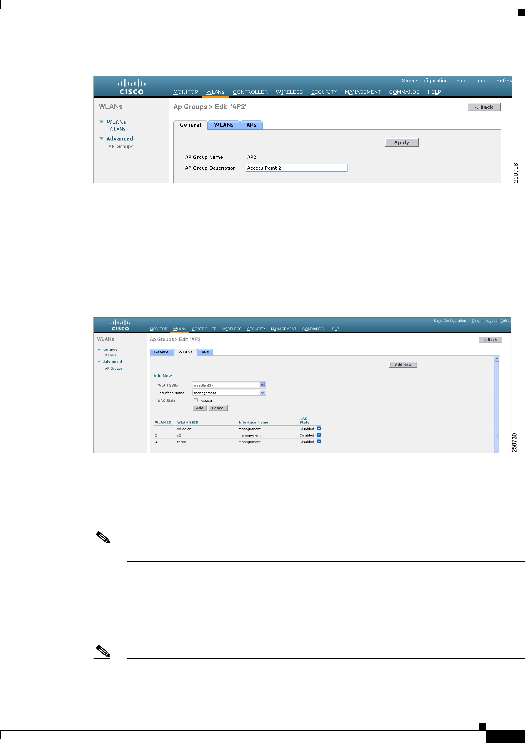
7-59
Cisco Wireless LAN Controller Configuration Guide
OL-21524-02
Chapter 7 Configuring WLANs
Configuring DHCP
Figure 7-24 AP Groups > Edit (General) Page
Step 7 Change the description of this access point group by entering the new text in the AP Group Description
text box and click Apply.
Step 8 Choose the WLANs tab to open the AP Groups > Edit (WLANs) page. This page lists the WLANs that
are currently assigned to this access point group.
Step 9 Click Add New to assign a WLAN to this access point group. The Add New section appears at the top
of the page (see Figure 7-25).
Figure 7-25 AP Groups > Edit (WLANs) Page
Step 10 From the WLAN SSID drop-down list, choose the SSID of the WLAN.
Step 11 From the Interface Name drop-down list, choose the interface to which you want to map the access point
group. Choose the quarantine VLAN if you plan to enable network admission control (NAC) out-of-band
support.
Note The interface name in the default-group access point group matches the WLAN interface.
Step 12 Select the NAC State check box to enable NAC out-of-band support for this access point group. To
disable NAC out-of-band support, leave the check box unselected, which is the default value. See the
“Configuring NAC Out-of-Band Integration” section on page 7-68 for more information on NAC.
Step 13 Click Add to add this WLAN to the access point group. This WLAN appears in the list of WLANs that
are assigned to this access point group.
Note If you ever want to remove this WLAN from the access point group, hover your cursor over the
blue drop-down arrow for the WLAN and choose Remove.
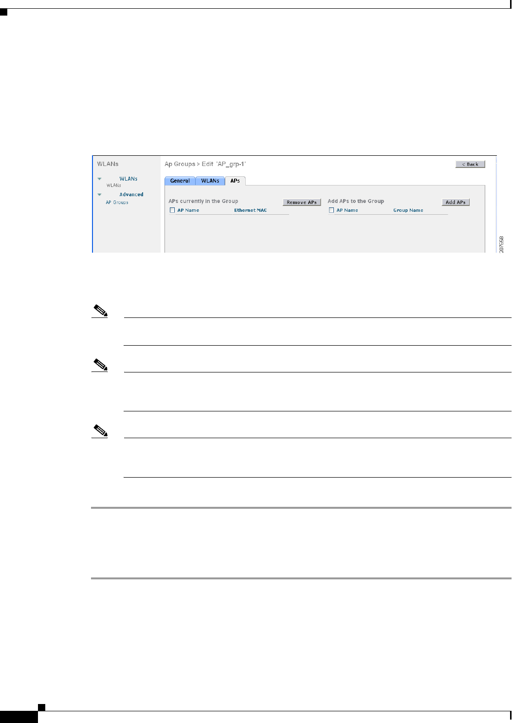
7-60
Cisco Wireless LAN Controller Configuration Guide
OL-21524-02
Chapter 7 Configuring WLANs
Configuring DHCP
Step 14 Repeat Step 9 through Step 13 to add any additional WLANs to this access point group.
Step 15 Choose the APs tab to assign access points to this access point group. The AP Groups > Edit (APs) page
lists the access points that are currently assigned to this group as well as any access points that are
available to be added to the group. If an access point is not currently assigned to a group, its group name
appears as “default-group” (see Figure 7-26).
Figure 7-26 AP Groups > Edit (APs) Page
Step 16 Select the check box to the left of the access point name and click Add APs to add an access point to
this access point group. The access point now appears in the list of access points currently in this access
point group.
Note To select all of the available access points at once, select the AP Name check box. All of the
access points are then selected.
Note If you ever want to remove an access point from the group, select the check box to the left of the
access point name and click Remove APs. To select all of the access points at once, select the
AP Name check box. All of the access points are then removed from this group.
Note If you ever want to change the access point group to which an access point belongs, choose
Wireless > Access Points > All APs > ap_name > Advanced tab, choose the name of another
access point group from the AP Group Name drop-down list, and click Apply.
Step 17 Click Save Configuration to save your changes.
Using the CLI to Create Access Point Groups
To create access point groups using the controller CLI, follow these steps:
Step 1 Create an access point group by entering this command:
config wlan apgroup add group_name

7-61
Cisco Wireless LAN Controller Configuration Guide
OL-21524-02
Chapter 7 Configuring WLANs
Configuring DHCP
Note To delete an access point group, enter the config wlan apgroup delete group_name command.
An error message appears if you try to delete an access point group that is used by at least one
access point. Before deleting an access point group in controller software release 6.0 or later
releases, move all access points in the group to another group. The access points are not moved
to the default-group access point group as in previous releases. To see the access points in a
group, enter the show wlan apgroups command. To move the access points to another group,
enter the config ap group-name group_name Cisco_AP command.
Step 2 Add a description to an access point group by entering this command:
config wlan apgroup description group_name description
Step 3 Assign a WLAN to an access point group by entering this command:
config wlan apgroup interface-mapping add group_name wlan_id interface_name
Note To remove a WLAN from an access point group, enter the config wlan apgroup
interface-mapping delete group_name wlan_id command.
Step 4 Enable or disable NAC out-of-band support for this access point group by entering this command:
config wlan apgroup nac {enable | disable} group_name wlan_id
Step 5 Assign an access point to an access point group by entering this command:
config ap group-name group_name Cisco_AP
Note To remove an access point from an access point group, reenter this command and assign the
access point to another group.
Step 6 Save your changes by entering this command:
save config
Using the CLI to View Access Point Groups
To view information about or to troubleshoot access point groups, use these commands:
• See a list of all access point groups on the controller by entering this command:
show wlan apgroups
Information similar to the following appears:
Site Name........................................ AP2
Site Description................................. Access Point 2
WLAN ID Interface Network Admission Control
------- ----------- --------------------------
1 management Disabled
2 management Disabled
3 management Disabled
4 management Disabled
9 management Disabled
10 management Disabled
11 management Disabled

7-62
Cisco Wireless LAN Controller Configuration Guide
OL-21524-02
Chapter 7 Configuring WLANs
Configuring DHCP
12 management Disabled
13 management Disabled
14 management Disabled
15 management Disabled
16 management Disabled
18 management Disabled
AP Name Slots AP Model Ethernet MAC Location Port Country Priority GroupName
------- ---- -------------- ----------------- ------- ---- ------- -------- ---------
AP1242 2 AP1242AG-A-K9 00:14:1c:ed:23:9a default 1 US 1 AP2
...
• See the BSSIDs for each WLAN assigned to an access point group by entering this command:
show ap wlan {802.11a | 802.11b} Cisco_AP
Information similar to the following appears:
Site Name........................................ AP3
Site Description................................. Access Point 3
WLAN ID Interface BSSID
------- ------------ -------------------
10 management 00:14:1b:58:14:df
• See the number of WLANs enabled for an access point group by entering this command:
show ap config {802.11a | 802.11b} Cisco_AP
Information similar to the following appears:
Cisco AP Identifier.............................. 166
Cisco AP Name................................. AP2
...
Station Configuration
Configuration ............................. AUTOMATIC
Number Of WLANs ........................... 2
...
• Enable or disable debugging of access point groups by entering this command:
debug group {enable | disable}
Configuring Web Redirect with 802.1X Authentication
You can configure a WLAN to redirect a user to a particular web page after 802.1X authentication has
completed successfully. You can configure the web redirect to give the user partial or full access to the
network.
Conditional Web Redirect
If you enable conditional web redirect, the user can be conditionally redirected to a particular web page
after 802.1X authentication has completed successfully. You can specify the redirect page and the
conditions under which the redirect occurs on your RADIUS server. Conditions might include the user’s
password reaching expiration or the user needing to pay his or her bill for continued usage.
If the RADIUS server returns the Cisco AV-pair “url-redirect,” then the user is redirected to the specified
URL upon opening a browser. If the server also returns the Cisco AV-pair “url-redirect-acl,” the specified
access control list (ACL) is installed as a preauthentication ACL for this client. The client is not
considered fully authorized at this point and can only pass traffic allowed by the preauthentication ACL.

7-63
Cisco Wireless LAN Controller Configuration Guide
OL-21524-02
Chapter 7 Configuring WLANs
Configuring DHCP
After the client completes a particular operation at the specified URL (for example, changing a password
or paying a bill), the client must reauthenticate. When the RADIUS server does not return a
“url-redirect,” the client is considered fully authorized and allowed to pass traffic.
Note The conditional web redirect feature is available only for WLANs that are configured for 802.1X or
WPA+WPA2 Layer 2 security.
After you configure the RADIUS server, you can then configure the conditional web redirect on the
controller using either the controller GUI or CLI.
Splash Page Web Redirect
If you enable splash page web redirect, the user is redirected to a particular web page after 802.1X
authentication has completed successfully. After the redirect, the user has full access to the network. You
can specify the redirect page on your RADIUS server. If the RADIUS server returns the Cisco AV-pair
“url-redirect,” then the user is redirected to the specified URL upon opening a browser. The client is
considered fully authorized at this point and is allowed to pass traffic, even if the RADIUS server does
not return a “url-redirect.”
Note The splash page web redirect feature is available only for WLANs that are configured for 802.1X or
WPA+WPA2 Layer 2 security with 802.1x key management. Preshared key management is not
supported with any Layer 2 security method.
After you configure the RADIUS server, you can then configure the splash page web redirect on the
controller using either the controller GUI or CLI.
Using the GUI to Configure the RADIUS Server
To configure your RADIUS server using the controller GUI, follow these steps:
Note These instructions are specific to the CiscoSecure ACS; however, they should be similar to those for
other RADIUS servers.
Step 1 From the CiscoSecure ACS main menu, choose Group Setup.
Step 2 Click Edit Settings.
Step 3 From the Jump To drop-down list, choose RADIUS (Cisco IOS/PIX 6.0). The dialog box shown in
Figure 7-27 appears.
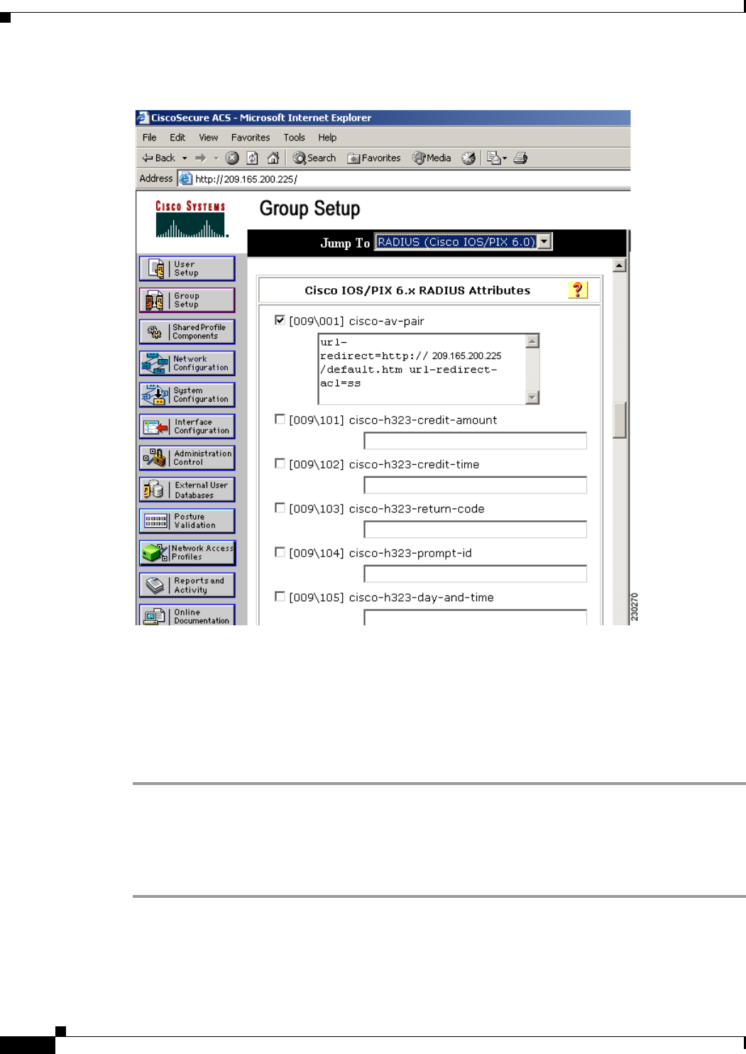
7-64
Cisco Wireless LAN Controller Configuration Guide
OL-21524-02
Chapter 7 Configuring WLANs
Configuring DHCP
Figure 7-27 ACS Server Configuration
Step 4 Select the [009\001] cisco-av-pair check box.
Step 5 Enter the following Cisco AV-pairs in the [009\001] cisco-av-pair edit box to specify the URL to which
the user is redirected and, if configuring conditional web redirect, the conditions under which the
redirect takes place, respectively:
url-redirect=http://url
url-redirect-acl=acl_name
Using the GUI to Configure Web Redirect
To configure conditional or splash page web redirect using the controller GUI, follow these steps:
Step 1 Choose WLANs to open the WLANs page.
Step 2 Click the ID number of the desired WLAN. The WLANs > Edit page appears.
Step 3 Choose the Security and Layer 2 tabs to open the WLANs > Edit (Security > Layer 2) page.
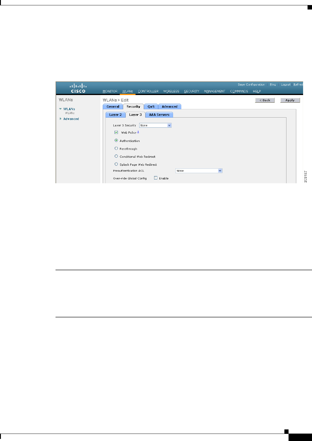
7-65
Cisco Wireless LAN Controller Configuration Guide
OL-21524-02
Chapter 7 Configuring WLANs
Configuring DHCP
Step 4 From the Layer 2 Security drop-down list, choose 802.1X or WPA+WPA2.
Step 5 Set any additional parameters for 802.1X or WPA+WPA2.
Step 6 Choose the Layer 3 tab to open the WLANs > Edit (Security > Layer 3) page (see Figure 7-28).
Figure 7-28 WLANs > Edit (Security > Layer 3) Page
Step 7 From the Layer 3 Security drop-down list, choose None.
Step 8 Check the Web Policy check box.
Step 9 Choose one of the following options to enable conditional or splash page web redirect: Conditional Web
Redirect or Splash Page Web Redirect. The default value is disabled for both parameters.
Step 10 If the user is to be redirected to a site external to the controller, choose the ACL that was configured on
your RADIUS server from the Preauthentication ACL drop-down list.
Step 11 Click Apply to commit your changes.
Step 12 Click Save Configuration to save your changes.
Using the CLI to Configure Web Redirect
To configure conditional or splash page web redirect using the controller CLI, follow these steps:
Step 1 Enable or disable conditional web redirect by entering this command:
config wlan security cond-web-redir {enable | disable} wlan_id
Step 2 Enable or disable splash page web redirect by entering this command:
config wlan security splash-page-web-redir {enable | disable} wlan_id
Step 3 Save your settings by entering this command:
save config
Step 4 See the status of the web redirect features for a particular WLAN by entering this command:
show wlan wlan_id
Information similar to the following appears:
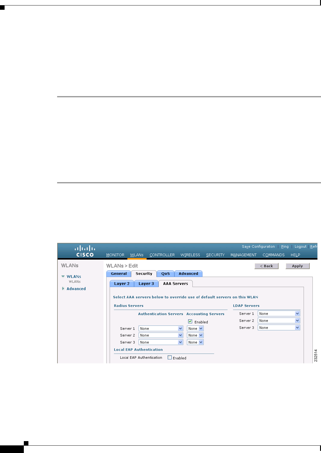
7-66
Cisco Wireless LAN Controller Configuration Guide
OL-21524-02
Chapter 7 Configuring WLANs
Configuring DHCP
WLAN Identifier.................................. 1
Profile Name..................................... test
Network Name (SSID).............................. test
...
Web Based Authentication......................... Disabled
Web-Passthrough.................................. Disabled
Conditional Web Redirect......................... Disabled
Splash-Page Web Redirect......................... Enabled
...
Using the GUI to Disable the Accounting Servers per WLAN
This section provides instructions for disabling all accounting servers on a WLAN. Disabling accounting
servers disables all accounting operations and prevents the controller from falling back to the default
RADIUS server for the WLAN.
To disable all accounting servers for a RADIUS authentication server using the controller GUI, follow
these steps:
Step 1 Choose WLANs to open the WLANs page.
Step 2 Click the ID number of the WLAN to be modified. The WLANs > Edit page appears.
Step 3 Choose the Security and AAA Servers tabs to open the WLANs > Edit (Security > AAA Servers) page
(see Figure 7-29).
Figure 7-29 WLANs > Edit (Security > AAA Servers) Page
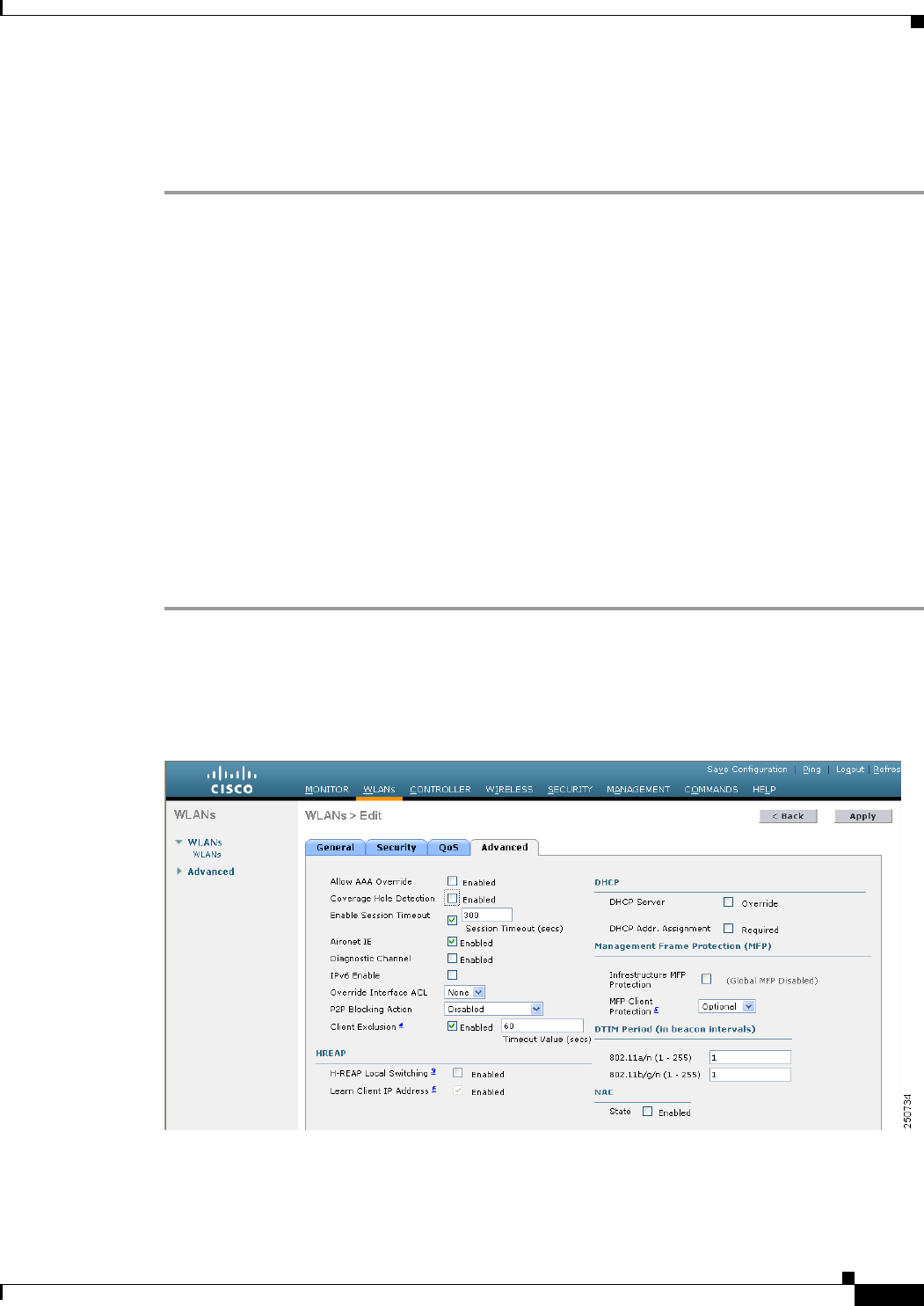
7-67
Cisco Wireless LAN Controller Configuration Guide
OL-21524-02
Chapter 7 Configuring WLANs
Configuring DHCP
Step 4 Unselect the Enabled check box for the Accounting Servers.
Step 5 Click Apply to commit your changes.
Step 6 Click Save Configuration to save your changes.
Disabling Coverage Hole Detection per WLAN
This section provides instructions for disabling coverage hole detection on a WLAN.
Coverage hole detection is enabled globally on the controller. See the “Coverage Hole Detection and
Correction” section on page 13-4 and the “Using the GUI to Configure Coverage Hole Detection”
section on page 13-20 for more information.
In software release 5.2 or later releases, you can disable coverage hole detection on a per-WLAN basis.
When you disable coverage hole detection on a WLAN, a coverage hole alert is still sent to the controller,
but no other processing is done to mitigate the coverage hole. This feature is useful for guest WLANs
where guests are connected to your network for short periods of time and are likely to be highly mobile.
Using the GUI to Disable Coverage Hole Detection on a WLAN
To disable coverage hole detection on a WLAN using the controller GUI, follow these steps:
Step 1 Choose WLANs to open the WLANs page.
Step 2 Click the profile name of the WLAN to be modified. The WLANs > Edit page appears.
Step 3 Choose the Advanced tab to display the WLANs > Edit (Advanced) page (see Figure 7-30).
Figure 7-30 WLANs > Edit (Advanced) Page
Step 4 Unselect the Coverage Hole Detection Enabled check box.

7-68
Cisco Wireless LAN Controller Configuration Guide
OL-21524-02
Chapter 7 Configuring WLANs
Configuring DHCP
Note OEAP 600 Series Access Points do not support coverage hole detection.
Step 5 Click Apply to commit your changes.
Step 6 Click Save Configuration to save your changes.
Using the CLI to Disable Coverage Hole Detection on a WLAN
To disable coverage hole detection on a WLAN using the controller CLI, follow these steps:
Step 1 Disable coverage hole detection on a by entering this command:
config wlan chd wlan_id disable
Note OEAP 600 Series Access Points do not support Coverage Hole detection.
Step 2 Save your settings by entering this command:
save config
Step 3 See the coverage hole detection status for a particular WLAN by entering this command:
show wlan wlan_id
Information similar to the following appears:
WLAN Identifier.................................. 2
Profile Name..................................... wlan2
Network Name (SSID).............................. 2
. . .
CHD per WLAN.................................. Disabled
Configuring NAC Out-of-Band Integration
The Cisco NAC Appliance, also known as Cisco Clean Access (CCA), is a network admission control
(NAC) product that allows network administrators to authenticate, authorize, evaluate, and remediate
wired, wireless, and remote users and their machines prior to allowing users onto the network. It
identifies whether machines are compliant with security policies and repairs vulnerabilities before
permitting access to the network. The NAC appliance is available in two modes: in-band and
out-of-band. Customers can deploy both modes if desired, each geared toward certain types of access
(in-band for supporting wireless users and out-of-band for supporting wired users, for example).
In controller software releases prior to 5.1, the controller integrates with the NAC appliance only in
in-band mode, where the NAC appliance must remain in the data path. For in-band mode, a NAC
appliance is required at each authentication location (such as at each branch or for each controller), and
all traffic must traverse the NAC enforcement point. In controller software release 5.1 or later releases,
the controller can integrate with the NAC appliance in out-of-band mode, where the NAC appliance
remains in the data path only until clients have been analyzed and cleaned. Out-of-band mode reduces
the traffic load on the NAC appliance and enables centralized NAC processing.
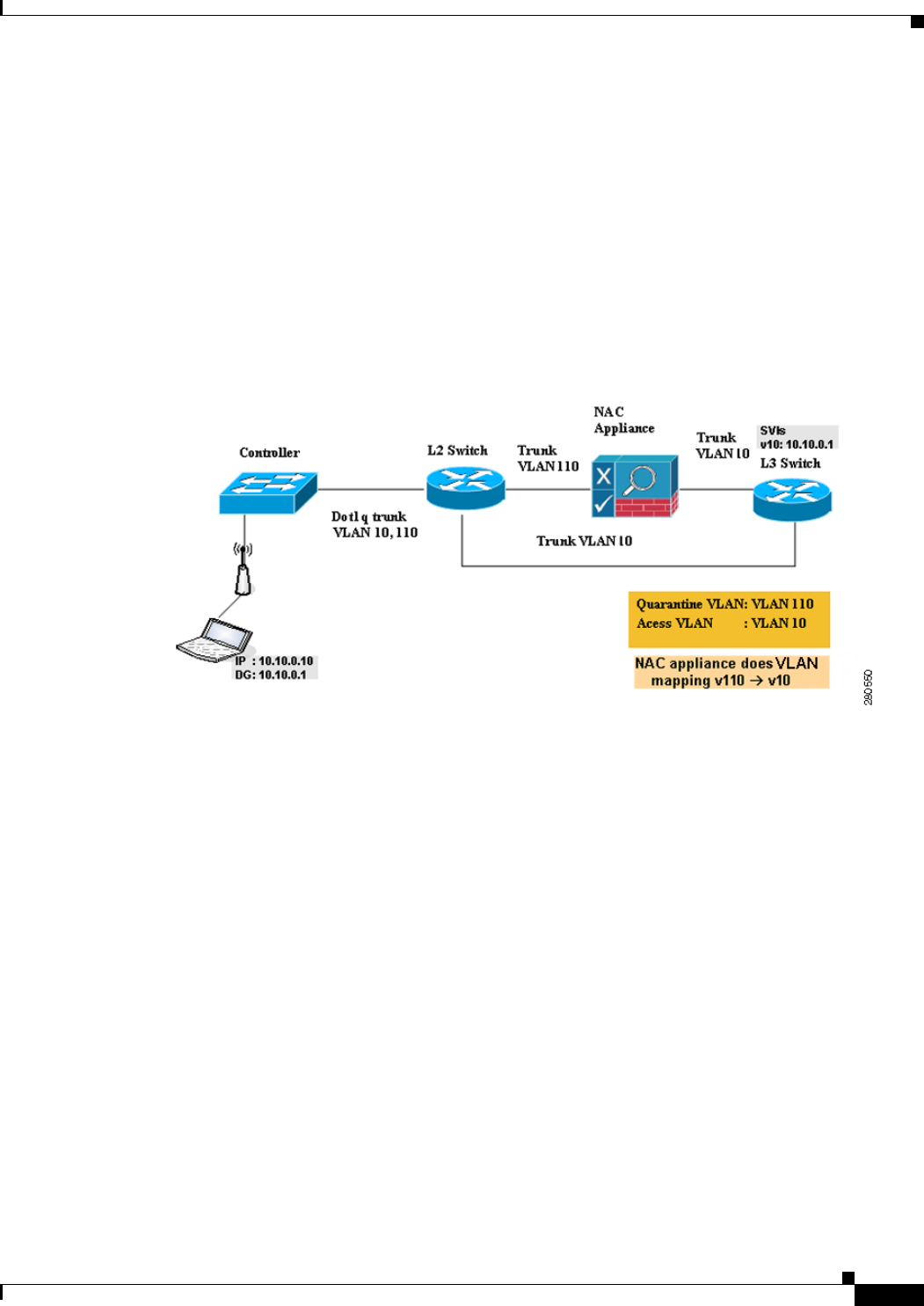
7-69
Cisco Wireless LAN Controller Configuration Guide
OL-21524-02
Chapter 7 Configuring WLANs
Configuring DHCP
To implement the NAC out-of-band feature on the controller, you must enable NAC support on the
WLAN or guest LAN and then map this WLAN or guest LAN to an interface that is configured with a
quarantine VLAN (untrusted VLAN) and an access VLAN (trusted VLAN). When a client associates
and completes Layer 2 authentication, the client obtains an IP address from the access VLAN subnet,
but the client state is Quarantine. While deploying the NAC out-of-band feature, be sure that the
quarantine VLAN is allowed only between the Layer 2 switch on which the controller is connected and
the NAC appliance and that the NAC appliance is configured with a unique quarantine-to-access VLAN
mapping. Client traffic passes into the quarantine VLAN, which is trunked to the NAC appliance. After
posture validation is completed, the client is prompted to take action for remediation. After cleaning is
completed, the NAC appliance updates the controller to change the client state from Quarantine to
Access. Figure 7-31 provides an example of NAC out-of-band integration.
Figure 7-31 NAC Out-of-Band Integration
In Figure 7-31, the link between the controller and the switch is configured as a trunk, enabling the
quarantine VLAN (110) and the access VLAN (10). On the Layer 2 switch, the quarantine traffic is
trunked to the NAC appliance while the access VLAN traffic goes directly to the Layer 3 switch. Traffic
that reaches the quarantine VLAN on the NAC appliance is mapped to the access VLAN based on a static
mapping configuration.
Follow the instructions in this section to configure NAC out-of-band integration using either the
controller GUI or CLI.
Guidelines for Using NAC Out-of-Band Integration
Follow these guidelines when using NAC out-of-band integration:
• The NAC appliance supports up to 3500 users, and the controller supports up to 5000 users. Multiple
NAC appliances might need to be deployed.
• CCA software release 4.5 or later releases is required for NAC out-of-band integration.
• Because the NAC appliance supports static VLAN mapping, you must configure a unique quarantine
VLAN for each interface configured on the controller. For example, you might configure a
quarantine VLAN of 110 on controller 1 and a quarantine VLAN of 120 on controller 2. However,
if two WLANs or guest LANs use the same distribution system interface, they must use the same
quarantine VLAN, provided they have one NAC appliance deployed in the network. The NAC
appliance supports unique quarantine-to-access VLAN mapping.

7-70
Cisco Wireless LAN Controller Configuration Guide
OL-21524-02
Chapter 7 Configuring WLANs
Configuring DHCP
• For posture reassessment based on session expiry, you must configure the session timeout on both
the NAC appliance and the WLAN, making sure that the session expiry on the WLAN is greater than
that on the NAC appliance.
• When a session timeout is configured on an open WLAN, the timing out of clients in the Quarantine
state is determined by the timer on the NAC appliance. Once the session timeout expires for WLANs
using web authentication, clients deauthenticate from the controller and must perform posture
validation again.
• NAC out-of-band integration is supported only on WLANs configured for hybrid-REAP central
switching. It is not supported for use on WLANs configured for hybrid-REAP local switching.
Note See Chapter 15, “Configuring Hybrid REAP,” for more information on hybrid REAP.
• If you want to enable NAC on an access point group VLAN, you must first enable NAC on the
WLAN. Then you can enable or disable NAC on the access point group VLAN. If you ever decide
to disable NAC on the WLAN, be sure to disable it on the access point group VLAN as well.
• NAC out-of-band integration is not supported for use with the WLAN AAA override feature.
• All Layer 2 and Layer 3 authentication occurs in the quarantine VLAN. To use external web
authentication, you must configure the NAC appliance to allow HTTP traffic to and from external
web servers and to allow the redirect URL in the quarantine VLAN.
Note See the Cisco NAC appliance configuration guides for configuration instructions:
http://www.cisco.com/en/US/products/ps6128/products_installation_and_configuration_gu
ides_list.html
Using the GUI to Configure NAC Out-of-Band Integration
To configure NAC out-of-band integration using the controller GUI, follow these steps:
Step 1 Configure the quarantine VLAN for a dynamic interface as follows:
a. Choose Controller > Interfaces to open the Interfaces page.
b. Click New to create a new dynamic interface.
c. In the Interface Name text box, enter a name for this interface, such as “quarantine.”
d. In the VLAN ID text box, enter a nonzero value for the access VLAN ID, such as “10.”
e. Click Apply to commit your changes. The Interfaces > Edit page appears (see Figure 7-32).
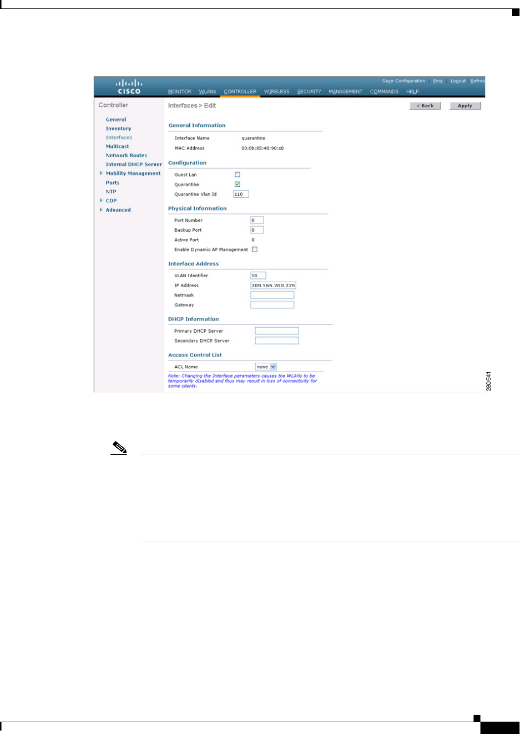
7-71
Cisco Wireless LAN Controller Configuration Guide
OL-21524-02
Chapter 7 Configuring WLANs
Configuring DHCP
Figure 7-32 Interfaces > Edit Page
f. Select the Quarantine check box and enter a nonzero value for the quarantine VLAN ID, such as
“110.”
Note We recommend that you configure unique quarantine VLANs throughout your network. If
multiple controllers are configured in the same mobility group and access interfaces on all
controllers are in the same subnet, it is mandatory to have the same quarantine VLAN if
there is only one NAC appliance in the network. If multiple controllers are configured in the
same mobility group and access interfaces on all controllers are in different subnets, it is
mandatory to have different quarantine VLANs if there is only one NAC appliance in the
network.
g. Configure any remaining text boxes for this interface, such as the IP address, netmask, and default
gateway.
h. Click Apply to save your changes.
Step 2 Configure NAC out-of-band support on a WLAN or guest LAN as follows:
a. Choose WLANs to open the WLANs page.
b. Click the ID number of the desired WLAN or guest LAN. The WLANs > Edit page appears.
c. Choose the Advanced tab to open the WLANs > Edit (Advanced) page (see Figure 7-33).
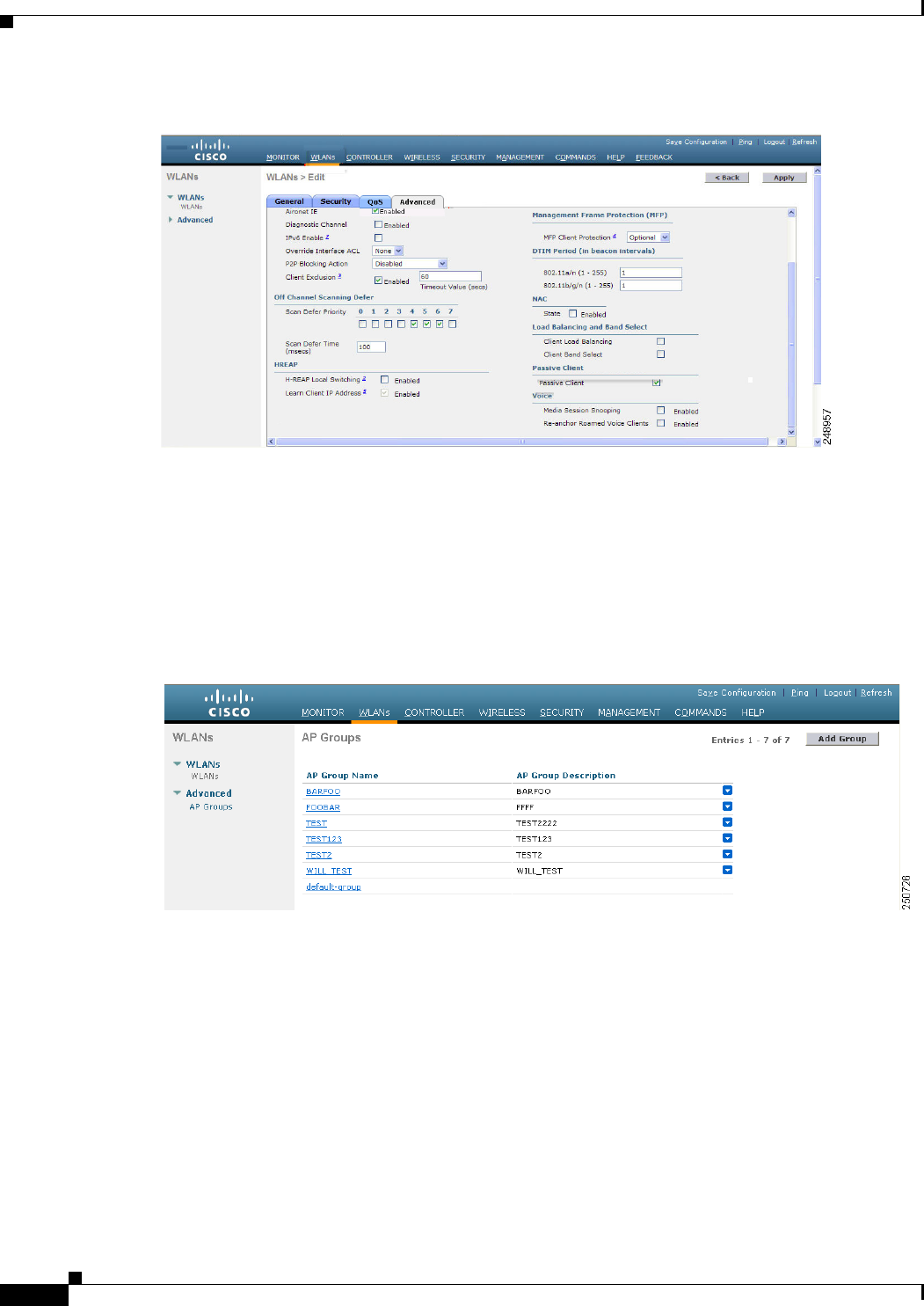
7-72
Cisco Wireless LAN Controller Configuration Guide
OL-21524-02
Chapter 7 Configuring WLANs
Configuring DHCP
Figure 7-33 WLANs > Edit (Advanced) Page
d. Configure NAC out-of-band support for this WLAN or guest LAN by selecting the NAC State check
box. To disable NAC out-of-band support, leave the check box unselected, which is the default
value.
e. Click Apply to commit your changes.
Step 3 Configure NAC out-of-band support for a specific access point group as follows:
a. Choose WLANs > Advanced > AP Groups to open the AP Groups page (see Figure 7-34).
Figure 7-34 AP Groups Page
b. Click the name of the desired access point group.
c. Choose the WLANs tab to open the AP Groups > Edit (WLANs) page.
d. Click Add New to assign a WLAN to this access point group. The Add New section appears at the
top of the page (see Figure 7-35).

7-73
Cisco Wireless LAN Controller Configuration Guide
OL-21524-02
Chapter 7 Configuring WLANs
Configuring DHCP
Figure 7-35 AP Groups > Edit (WLANs) Page
e. From the WLAN SSID drop-down list, choose the SSID of the WLAN.
f. From the Interface Name drop-down list, choose the interface to which you want to map the access
point group. Choose the quarantine VLAN if you plan to enable NAC out-of-band support.
g. To enable NAC out-of-band support for this access point group, select the NAC State check box. To
disable NAC out-of-band support, leave the check box unselected, which is the default value.
h. Click Add to add this WLAN to the access point group. This WLAN appears in the list of WLANs
assigned to this access point group.
Note If you ever want to remove this WLAN from the access point group, hover your cursor over the
blue drop-down arrow for the WLAN and choose Remove.
Step 4 Click Save Configuration to save your changes.
Step 5 See the current state of the client (Quarantine or Access) as follows:
a. Choose Monitor > Clients to open the Clients page.
b. Click the MAC address of the desired client to open the Clients > Detail page. The NAC state
appears under the Security Information section.
Note The client state appears as “Invalid” if the client is probing, has not yet associated to a
WLAN, or cannot complete Layer 2 authentication.
Using the CLI to Configure NAC Out-of-Band Integration
To configure NAC out-of-band integration using the controller CLI, follow these steps:
Step 1 Configure the quarantine VLAN for a dynamic interface by entering this command:
config interface quarantine vlan interface_name vlan_id
Note You must configure a unique quarantine VLAN for each interface on the controller.

7-74
Cisco Wireless LAN Controller Configuration Guide
OL-21524-02
Chapter 7 Configuring WLANs
Configuring DHCP
Note To disable the quarantine VLAN on an interface, enter 0 for the VLAN ID.
Step 2 Enable or disable NAC out-of-band support for a WLAN or guest LAN by entering this command:
config {wlan | guest-lan} nac {enable | disable} {wlan_id | guest_lan_id}
Step 3 Enable or disable NAC out-of-band support for a specific access point group by entering this command:
config wlan apgroup nac {enable | disable} group_name wlan_id
Step 4 Save your changes by entering this command:
save config
Step 5 See the configuration of a WLAN or guest LAN, including the NAC state by entering this command:
show {wlan wlan_ id | guest-lan guest_lan_id}
Information similar to the following appears:
WLAN Identifier.................................. 1
Profile Name..................................... wlan
Network Name (SSID).............................. wlan
Status........................................... Disabled
MAC Filtering.................................... Disabled
Broadcast SSID................................... Enabled
AAA Policy Override.............................. Disabled
Network Admission Control
NAC-State...................................... Enabled
Quarantine VLAN............................. 110
...
Step 6 See the current state of the client (either Quarantine or Access) by entering this command:
show client detailed client_mac
Information similar to the following appears:
Client’s NAC state.................................. QUARANTINE
Note The client state appears as “Invalid” if the client is probing, has not yet associated to a WLAN,
or cannot complete Layer 2 authentication.
Configuring Passive Client
Note The passive client feature is supported on Cisco 5500 and Cisco 2100 Series Controllers.
Note The passive client feature is not supported with the AP groups and hybrid REAP centrally switched
WLANs.

7-75
Cisco Wireless LAN Controller Configuration Guide
OL-21524-02
Chapter 7 Configuring WLANs
Configuring DHCP
Note The passive client feature works in multicast-multicast and multicast-unicast mode. The controller
sources the multicast packets using its management IP address.
Passive clients are wireless devices, such as scales and printers that are configured with a static IP
address. These clients do not transmit any IP information such as IP address, subnet mask, and gateway
information when they associate with an access point. As a result, when passive clients are used, the
controller never knows the IP address unless they use the DHCP.
Wireless LAN controllers currently act as a proxy for ARP requests. Upon receiving an ARP request,
the controller responds with an ARP response instead of passing the request directly to the client. This
scenario has two advantages:
• The upstream device that sends out the ARP request to the client will not know where the client is
located.
• Power for battery-operated devices such as mobile phones and printers is preserved because they do
not have to respond to every ARP requests.
Since the wireless controller does not have any IP related information about passive clients, it cannot
respond to any ARP requests. The current behavior does not allow the transfer of ARP requests to passive
clients. Any application that tries to access a passive client will fail.
The passive client feature enables the ARP requests and responses to be exchanged between wired and
wireless clients. This feature when enabled, allows the controller to pass ARP requests from wired to
wireless clients until the desired wireless client gets to the RUN state.
Using the GUI to Configure Passive Client
This section describes how to configure passive client using the controller GUI.
Note You can configure passive clients in multicast-multicast or multicast-unicast mode.
Enabling the Multicast-Multicast Mode
To enable the multicast-multicast mode, follow these steps:
Step 1 Choose Controller > General to open the General page. See Figure 7-36.
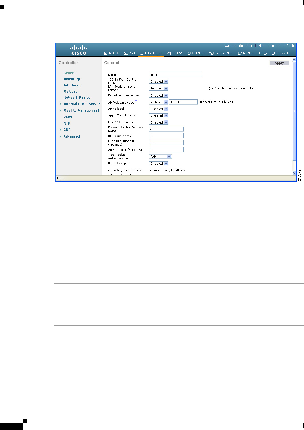
7-76
Cisco Wireless LAN Controller Configuration Guide
OL-21524-02
Chapter 7 Configuring WLANs
Configuring DHCP
Figure 7-36 Controller > General Page
Step 2 Choose one of the following options from the AP Multicast Mode drop-down list:
• Unicast—Configures the controller to use the unicast method to send multicast packets. This is the
default value.
• Multicast—Configures the controller to use the multicast method to send multicast packets to a
CAPWAP multicast group.
Step 3 Select Multicast from the AP Multicast Mode drop-down list. The Multicast Group Address text box is
displayed.
Step 4 In the Multicast Group Address text box, enter the IP address of the multicast group.
Step 5 Click Apply to commit your changes.
Step 6 Click Multicast to enable the global multicast mode (see Figure 7-37).
Enabling the Global Multicast Mode on Controllers
To enable the global multicast mode, follow these steps:
Step 1 Choose Controller > Multicast to open the Multicast page (see Figure 7-37.)

7-77
Cisco Wireless LAN Controller Configuration Guide
OL-21524-02
Chapter 7 Configuring WLANs
Configuring DHCP
Figure 7-37 Multicast Page
Note The Enable IGMP Snooping text box is highlighted only when you enable the Enable Global Multicast
mode. The IGMP Timeout (seconds) text box is highlighted only when you enable the Enable IGMP
Snooping text box.
Step 2 Select the Enable Global Multicast Mode check box to enable the multicast mode. This step configures
the controller to use the multicast method to send multicast packets to a CAPWAP multicast group.
Step 3 Select the Enable IGMP Snooping check box to enable the IGMP snooping. The default value is
disabled.
Step 4 In the IGMP Timeout text box to set the IGMP timeout, enter a value between 30 and 7200 seconds.
Step 5 Click Apply to commit your changes.
Enabling the Passive Client Feature on the Controller
To enable the passive client feature on the controller, follow these steps:
Step 1 Choose WLANs > WLANs > WLAN ID to open the WLANs > Edit page (see Figure 7-38). By default,
the General tab is displayed.
Step 2 Choose the Advanced tab.
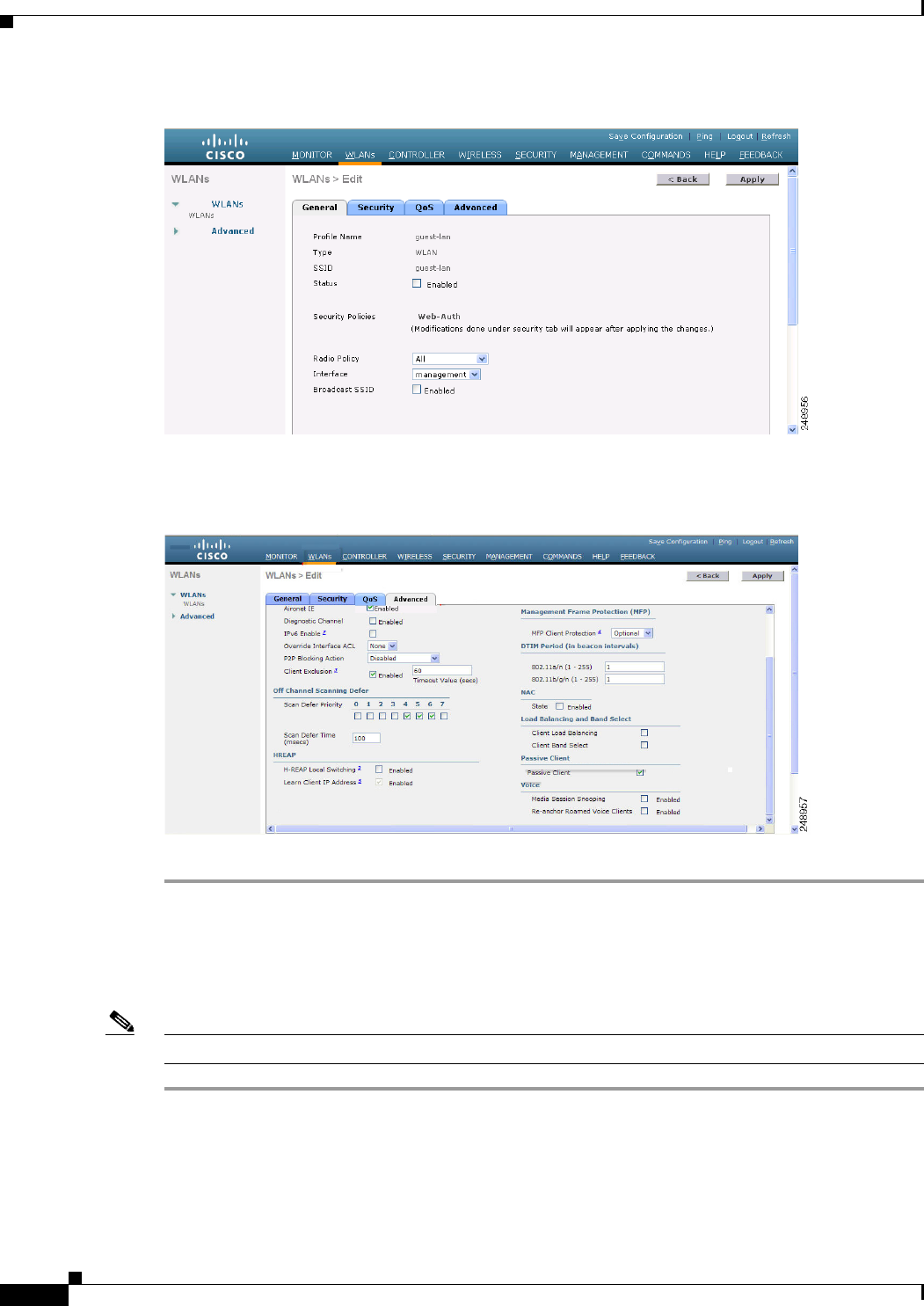
7-78
Cisco Wireless LAN Controller Configuration Guide
OL-21524-02
Chapter 7 Configuring WLANs
Configuring DHCP
Figure 7-38 WLAN > Edit Page
Step 3 Select the Passive Client check box (see Figure 7-39) to enable the passive client feature.
Figure 7-39 WLAN > Edit > Advanced Tab Page
Step 4 Click Apply to commit your changes.
Using the CLI to Configure Passive Client
To configure passive client using the controller CLI, follow these steps:
Note Make sure that you enable the multicast mode before you configure the passive client feature.
Step 1 Enable or disable multicasting on the controller by entering this command:
config network multicast global {enable | disable}
The default value is disabled.
Step 2 Configure the controller to use multicast to send multicast to an access point by entering this command:

7-79
Cisco Wireless LAN Controller Configuration Guide
OL-21524-02
Chapter 7 Configuring WLANs
Configuring DHCP
config network multicast mode multicast multicast_group_IP_address
Step 3 Configure passive client on a wireless LAN by entering this command:
config wlan passive-client {enable | disable} wlan_id
Step 4 Configure a WLAN by entering this command:
config wlan
Step 5 Save your changes by entering this command:
save config
Step 6 Display the passive client information on a particular WLAN by entering this command:
show wlan 2
Information similar to the following appears:
WLAN Identifier.................................. 2
Profile Name..................................... passive
Network Name (SSID).............................. passive
Status........................................... Enabled
MAC Filtering.................................... Disabled
Broadcast SSID................................... Enabled
AAA Policy Override.............................. Disabled
Network Admission Control
NAC-State.............................Disabled
Quarantine VLAN.......................0
Number of Active Clients................1
Exclusionlist Timeout...................60 seconds
Session Timeout.........................1800 seconds
CHD per WLAN............................Enabled
Webauth DHCP exclusion..................Disabled
Interface...............................management
WLAN ACL................................unconfigured
DHCP Server.............................Default
DHCP Address Assignment Required......Disabled
--More-- or (q)uit
Quality of Service............................... Silver (best effort)
WMM.............................................. Allowed
CCX - AironetIe Support.......................... Enabled
CCX - Gratuitous ProbeResponse (GPR)............. Disabled
CCX - Diagnostics Channel Capability............. Disabled
Dot11-Phone Mode (7920).......................... Disabled
Wired Protocol................................... None
IPv6 Support..................................... Disabled
Passive Client Feature........................... Enabled
Peer-to-Peer Blocking Action..................... Disabled
Radio Policy..................................... All
DTIM period for 802.11a radio.................... 1
DTIM period for 802.11b radio.................... 1
Radius Servers
Authentication................................ Global Servers
Accounting.................................... Global Servers
Local EAP Authentication......................... Disabled
Security
802.11 Authentication:........................ Open System
Static WEP Keys............................... Disabled
802.1X........................................ Disabled
Wi-Fi Protected Access (WPA/WPA2)............. Disabled
--More-- or (q)uit
CKIP ......................................... Disabled
Web Based Authentication...................... Disabled
Web-Passthrough............................... Disabled
Conditional Web Redirect...................... Disabled

7-80
Cisco Wireless LAN Controller Configuration Guide
OL-21524-02
Chapter 7 Configuring WLANs
Configuring DHCP
Splash-Page Web Redirect...................... Disabled
Auto Anchor................................... Disabled
H-REAP Local Switching........................ Disabled
H-REAP Learn IP Address....................... Enabled
Infrastructure MFP protection................. Enabled (Global Infrastructure MFP
Disabled)
Client MFP.................................... Optional but inactive (WPA2 not
configured)
Tkip MIC Countermeasure Hold-down Timer....... 60
Call Snooping.................................... Disabled
Band Select...................................... Enabled
Load Balancing................................... Enabled
Step 7 Verify if the passive client is associated correctly with the AP and if the passive client has moved into
the DHCP required state at the controller by entering this command:
debug client mac_address
Step 8 Display the detailed information for a client by entering this command:
show client detail mac_address
Information similar to the following appears:
Client MAC Address............................... 00:0d:28:f4:c0:45
Client Username ................................. N/A
AP MAC Address................................... 00:14:1b:58:19:00
Client State..................................... Associated
Client NAC OOB State............................. Access
Wireless LAN Id.................................. 1
BSSID............................................ 00:14:1b:58:19:00
Connected For ................................... 8 secs
Channel.......................................... 11
IP Address....................................... Unknown
………………………
Security Policy Completed........................ No
Policy Manager State............................. DHCP_REQD
Policy Manager Rule Created...................... Yes
ACL Name......................................... none
ACL Applied Status............................... Unavailable
Step 9 Check if the client moves into the run state, when a wired client tries to contact the client by entering
this command:
debug client mac_address
Step 10 Configure and check if the arp request is forwarded from the wired side to the wireless side by entering
this command:
debug arp all enable
Information similar to the following appears:
*dtlArpTask: Apr 15 10:54:26.161: Received dtlArpRequest
sha: 00:19:06:61:b1:c3 spa: 80.4.1.1
tha: 00:00:00:00:00:00 tpa: 80.4.0.50
intf: 1, vlan: 71, node type: 1, mscb: not found, isFromSta: 0^M^M
*dtlArpTask: Apr 15 10:54:26.161: dtlArpFindClient:ARP look-up for 80.4.0.50 failed (not a
client).
*dtlArpTask: Apr 15 10:54:26.161: Dropping ARP to DS (mscb (nil), port 65535)
sha 0019.0661.b1c3 spa: 80.4.1.1
tha 0000.0000.0000 tpa: 80.4.0.50
*dtlArpTask: Apr 15 10:54:26.161: Arp from Wired side to passive client

7-81
Cisco Wireless LAN Controller Configuration Guide
OL-21524-02
Chapter 7 Configuring WLANs
Configuring DHCP
*dtlArpTask: Apr 15 10:54:27.465: dtlArpBcastRecv: received packet (rxTunType 1, dataLen
122)
Per-WLAN RADIUS Source Support
By default, the controller sources all RADIUS traffic from the IP address on its management interface.
This means that even if a WLAN has specific RADIUS servers configured instead of the global list, the
identity used is the management interface IP address.
If you want to do a per-user WLAN filtering, you can use the callStationID set by RFC 3580 to be in the
APMAC:SSID format. You can also extend the filtering on the authentication server to be on a
per-WLAN source interface by using the NAS-IP-Address attribute.
When the per-WLAN RADIUS source support is enabled, the controller sources all RADIUS traffic for
a particular WLAN using the dynamic interface that is configured. Also, RADIUS attributes are
modified accordingly to match the identity. This feature effectively virtualizes the controller on the
per-WLAN RADIUS traffic, where each WLAN can have a separate L3 identity. This feature is useful
in ACS Network Access Restrictions, Network Access Profiles, and so on.
This feature can be combined with normal RADIUS traffic source, with some WLANs using the
management interface and others using the per-WLAN dynamic interface as the address source.
Configuring Per-WLAN RADIUS Source Support
You can configure the per-WLAN RADIUS source support using only the controller CLI:
Step 1 Enter the config wlan disable wlan-id command to disable the WLAN.
Step 2 Enter the following command to enable or disable the per-WLAN RADIUS source support:
config wlan radius_server overwrite-interface {enable | disable} wlan-id
Note When enabled, the controller uses the interface specified on the WLAN configuration as identity and
source for all RADIUS related traffic on that WLAN.
When disabled, the controller uses the management interface as the identity in the NAS-IP-Address
attribute. If the RADIUS server is on a directly connected dynamic interface, the RADIUS traffic will
be sourced from that interface. Otherwise, the management IP address is used. In all cases, the
NAS-IP-Address attribute remains the management interface, unless the feature is enabled.
Step 3 Enter the config wlan enable wlan-id command to enable the WLAN.
Note You can filter requests on the RADIUS server side using CiscoSecure ACS. You can filter (accept or
reject) a request depending on the NAS-IP-Address attribute through a Network Access Restrictions
rule. The filtering to be used is the CLI/DNIS filtering.

7-82
Cisco Wireless LAN Controller Configuration Guide
OL-21524-02
Chapter 7 Configuring WLANs
Configuring DHCP
Monitoring the Status of Per-WLAN RADIUS Source Support
To see if the feature is enabled or disabled, enter the following command:
show wlan wlan-id
Example
The following example shows that the per-WLAN RADIUS source support is enabled on WLAN 1.
show wlan 1
Information similar to the following is displayed:
WLAN Identifier.................................. 4
Profile Name..................................... 4400-wpa2
Network Name (SSID).............................. 4400-wpa2
Status........................................... Enabled
MAC Filtering.................................... Disabled
Broadcast SSID................................... Enabled
AAA Policy Override.............................. Disabled
Network Admission Control
...
Radius Servers
Authentication................................ Global Servers
Accounting.................................... Global Servers
Overwrite Sending Interface................... Enabled
Local EAP Authentication......................... Disabled
Guidelines and Limitations
• It is up to the authentication server (RADIUS) to implement a proper rule filtering on the new
identity because the controller sources traffic only from the selected interface.
• callStationID is always in the APMAC:SSID format to comply with 802.1x over RADIUS RFC.
This is also a legacy behavior. Web-auth can use different formats available in the config radius
callStationIDType command.
• If AP groups or AAA override are used, the source interface remains the WLAN interface, and not
what is specified on the new AP group or RADIUS profile configuration.
Configuring Remote LANs
This section describes how to configure remote LANs using the controller GUI and CLI.
Caution You must remove all remote LANs from a controller's configuration before moving to a release that does
not support the remote LAN functionality. The remote LAN changes to a WLAN in earlier releases,
which could cause an undesirable or unsecured WLAN being broadcast on the wireless network.
Remote LAN is only supported in release 7.0.116.0 and later.
Note Only four clients can connect to an OEAP 600 series access point through a remote LAN port. This
number does not affect the fifteen WLAN limit imposed for the controller WLANs. The remote LAN
client limit supports connecting a switch or hub to the remote LAN port for multiple devices or
connecting directly to a Cisco IP phone that is connected to that port. Only the first four devices can
connect until one of the devices is idle for more than one minute.

7-83
Cisco Wireless LAN Controller Configuration Guide
OL-21524-02
Chapter 7 Configuring WLANs
Configuring DHCP
Note Remote LAN can be applied on a dedicated LAN port on an OEAP 600 series access point.
Using the GUI to Configure a Remote LAN
To create remote LANs using the controller GUI, follow these steps:
Step 1 Choose WLANs to open the WLANs page.
This page lists all of the WLANs and remote LANs currently configured on the controller. For each
WLAN, you can see its WLAN/remote LAN ID, profile name, type, SSID, status, and security policies.
The total number of WLANs/Remote LANs appears in the upper right-hand corner of the page. If the
list of WLANs/Remote LANs spans multiple pages, you can access these pages by clicking the page
number links.
Note If you want to delete a Remote LAN, hover your cursor over the blue drop-down arrow for that
WLAN and choose Remove, or select the check box to the left of the row, choose Remove
Selected from the drop-down list, and click Go. A message appears asking you to confirm your
decision. If you proceed, the remote LAN is removed from any access point group to which it is
assigned and from the access point’s radio.
Step 2 Create a new Remote-LAN by choosing Create New from the drop-down list and clicking Go. The
WLANs > New page appears.
Step 3 From the Type drop-down list, choose Remote LAN to create a remote LAN.
Step 4 In the Profile Name text box, enter up to 32 alphanumeric characters for the profile name to be assigned
to this Remote WLAN. The profile name must be unique.
Step 5 From the WLAN ID drop-down list, choose the ID number for this WLAN.
Step 6 Click Apply to commit your changes. The WLANs > Edit page appears (see Figure 7-3).
Note You can also open the WLANs > Edit page from the WLANs page by clicking the ID number of
the WLAN that you want to edit.
Step 7 Use the parameters on the General, Security, and Advanced tabs to configure this remote LAN. See the
sections in the rest of this chapter for instructions on configuring specific features.
Step 8 On the General tab, select the Status check box to enable this remote LAN. Be sure to leave it unselected
until you have finished making configuration changes to the remote LAN.
Note You can also enable or disable remote LANs from the WLANs page by selecting the check boxes
to the left of the IDs that you want to enable or disable, choosing Enable Selected or Disable
Selected from the drop-down list, and clicking Go.
Step 9 Click Apply to commit your changes.
Step 10 Click Save Configuration to save your changes.

7-84
Cisco Wireless LAN Controller Configuration Guide
OL-21524-02
Chapter 7 Configuring WLANs
Configuring DHCP
Using the CLI to Configure a Remote LAN
To configure 802.1X for a remote LAN using the controller CLI, use the following commands:
• See the current configuration of the remote LAN by entering this command:
show remote-lan remote-lan-id
• Enable or disable remote LAN by entering this command:
config remote-lan {enable | disable} remote-lan-id
• Enable or disable 802.1X authentication for remote LAN by entering this command:
config remote-lan security 802.1X {enable | disable} remote-lan-id
Caution The 802.1x authentication settings for a Remote LAN can only be configured or modified using the
controller CLI. If a remote LAN is accessed through the controller GUI and any configuration changes
are performed; regardless of any modifications from the GUI; the 802.1x settings for that remote LAN
will be removed and whatever settings are shown in the GUI will be applied.
Note The encryption on a remote LAN is always “none”.
• Enable or disable local EAP with the controller as an authentication server, by entering this
command:
config remote-lan local-auth enable profile-name remote-lan-id
• If you are using an external AAA authentication server, use the following command:
config remote-lan radius_server auth {add | delete} remote-lan-id server id
config remote-lan radius_server auth {enable | disable} remote-lan-id

CHAPTER
8-1
Cisco Wireless LAN Controller Configuration Guide
OL-21524-02
8
Controlling Lightweight Access Points
This chapter describes the Cisco lightweight access points and explains how to connect them to the
controller and manage access point settings. It contains these sections:
• Access Point Communication Protocols, page 8-2
• Using the GUI to Search Access Point Radios, page 8-31
• Configuring Global Credentials for Access Points, page 8-33
• Configuring Authentication for Access Points, page 8-37
• Embedded Access Points, page 8-41
• Autonomous Access Points Converted to Lightweight Mode, page 8-43
• OfficeExtend Access Points, page 8-69
• Cisco Workgroup Bridges, page 8-88
• Configuring Backup Controllers, page 8-95
• Configuring Failover Priority for Access Points, page 8-101
• Configuring Country Codes, page 8-106
• Migrating Access Points from the -J Regulatory Domain to the -U Regulatory Domain, page 8-111
• Using the W56 Band in Japan, page 8-114
• Dynamic Frequency Selection, page 8-115
• Optimizing RFID Tracking on Access Points, page 8-116
• Using the CLI to Configure Probe Request Forwarding, page 8-119
• Retrieving the Unique Device Identifier on Controllers and Access Points, page 8-120
• Performing a Link Test, page 8-121
• Configuring Link Latency, page 8-124
• Configuring the TCP MSS, page 8-127
• Configuring Power over Ethernet, page 8-128
• Configuring Flashing LEDs, page 8-132
• Viewing Clients, page 8-133

8-2
Cisco Wireless LAN Controller Configuration Guide
OL-21524-02
Chapter 8 Controlling Lightweight Access Points
Access Point Communication Protocols
Access Point Communication Protocols
In controller software release 5.2 or later releases, Cisco lightweight access points use the IETF standard
Control and Provisioning of Wireless Access Points Protocol (CAPWAP) to communicate with the
controller and other lightweight access points on the network. Controller software releases prior to 5.2
use the Lightweight Access Point Protocol (LWAPP) for these communications.
CAPWAP, which is based on LWAPP, is a standard, interoperable protocol that enables a controller to
manage a collection of wireless access points. CAPWAP is being implemented in controller software
release 5.2 and later releases for these reasons:
• To provide an upgrade path from Cisco products that use LWAPP to next-generation Cisco products
that use CAPWAP
• To manage RFID readers and similar devices
• To enable controllers to interoperate with third-party access points in the future
LWAPP-enabled access points can discover and join a CAPWAP controller, and conversion to a
CAPWAP controller is seamless. For example, the controller discovery process and the firmware
downloading process when using CAPWAP are the same as when using LWAPP. The one exception is
for Layer 2 deployments, which are not supported by CAPWAP.
You can deploy CAPWAP controllers and LWAPP controllers on the same network. The
CAPWAP-enabled software allows access points to join either a controller running CAPWAP or LWAPP.
The only exceptions are that the Cisco Aironet 1260 and 3500 Series Access Points, which support only
CAPWAP and join only controllers that run CAPWAP. For example, an 1130 series access point can join
a controller running either CAPWAP or LWAPP where an1140 series access point can join only a
controller that runs CAPWAP.
Guidelines for Using CAPWAP
Follow these guidelines when using CAPWAP:
• If your firewall is currently configured to allow traffic only from access points using LWAPP, you
must change the rules of the firewall to allow traffic from access points using CAPWAP.
• Make sure that the CAPWAP UDP ports 5246 and 5247 (similar to the LWAPP UDP ports 12222
and 12223) are enabled and are not blocked by an intermediate device that could prevent an access
point from joining the controller.
• If access control lists (ACLs) are in the control path between the controller and its access points,
you need to open new protocol ports to prevent access points from being stranded.
Configuring Data Encryption
Cisco 5500 Series Controllers enable you to encrypt CAPWAP control packets (and optionally,
CAPWAP data packets) that are sent between the access point and the controller using Datagram
Transport Layer Security (DTLS). DTLS is a standards-track Internet Engineering Task Force (IETF)
protocol based on TLS. CAPWAP control packets are management packets exchanged between a
controller and an access point while CAPWAP data packets encapsulate forwarded wireless frames.
CAPWAP control and data packets are sent over separate UDP ports: 5246 (control) and 5247 (data). If
an access point does not support DTLS data encryption, DTLS is enabled only for the control plane, and
a DTLS session for the data plane is not established.

8-3
Cisco Wireless LAN Controller Configuration Guide
OL-21524-02
Chapter 8 Controlling Lightweight Access Points
Access Point Communication Protocols
Note Cisco 1130 and 1240 series access points support DTLS data encryption with software-based encryption,
and 1040, 1140, 1250, 1260, and 3500 series access points support DTLS data encryption with
hardware-based encryption.
DTLS data encryption is enabled automatically for OfficeExtend access points but disabled by default
for all other access points. Most access points are deployed in a secure network within a company
building, so data encryption is not necessary. In contrast, the traffic between an OfficeExtend access
point and the controller travels through an unsecure public network, so data encryption is more important
for these access points. When data encryption is enabled, traffic is encrypted at the access point before
it is sent to the controller and at the controller before it is sent to the client.
Note Encryption limits throughput at both the controller and the access point, and maximum throughput is
desired for most enterprise networks.
Caution In a Cisco unified local wireless network environment, do not enable DTLS on the Cisco 1130 and 1240
access points, as it may result in severe throughput degradation and may render the APs unusable.
Note See the“OfficeExtend Access Points” section on page 8-69 for more information on OfficeExtend access
points.
You can use the controller GUI or CLI to enable or disable DTLS data encryption for a specific access
point or for all access points.
The availability of data DTLS for the 7.0.116.0 release is as follows:
• The Cisco 5500 Series Controller will be available with two licenses options: One that allows data
DTLS without any license requirements and another image that requires a license to use data DTLS.
See “Upgrading or Downgrading DTLS Images for Cisco 5500 Series Controllers” section on
page 8-4. The images for the DTLS and licensed DTLS images are as follows:
–
Licensed DTLS—AS_5500_LDPE_x_x_x_x.aes
–
Non licensed DTLS—AS_5500_x_x_x_x.aes
• Cisco 2500, WiSM2, WLC2—By default, these platforms do not contain DTLS. To turn on data
DTLS, you must install a license. These platforms have a single image with data DTLS turned off.
To use data DTLS you will need to have a license.
Note If your controller does not have a data DTLS license and if the access point associated with the
controller has DTLS enabled, the data path will be unencrypted.
Note Non Russian customers using Cisco 5508 Series Controller do not need data DTLS license.
However all customers using WISM2 and Cisco 2500 Series Controllers must enable data DTLS.

8-4
Cisco Wireless LAN Controller Configuration Guide
OL-21524-02
Chapter 8 Controlling Lightweight Access Points
Access Point Communication Protocols
Upgrading or Downgrading DTLS Images for Cisco 5500 Series Controllers
A regular image (DTLS enabled) can be upgraded or downgraded to a licensed DTLS image using the
following two step process:
Step 1 The upgrade operation fails on first attempt with a warning indicating that the upgrade to a licensed
DTLS image is irreversible.
Step 2 On a subsequent attempt, the license is applied and the image is successfully updated.
Note The controller must not be rebooted after step 1.
The following are some of the guidelines when upgrading to or from a DTLS image:
• You cannot install a regular image (non-Licensed data DTLS) once a licensed data DTLS image is
installed.
• You can upgrade from one licensed DTLS image to another licensed DTLS image.
• You can upgrade from a regular image (DTLS) to a licensed DTLS image in a two step process.
Using the GUI to Configure Data Encryption
To enable DTLS data encryption for access points on the controller using the controller GUI, follow
these steps:
Step 1 Make sure that the base license is installed on the Cisco 5500 Series Controller. Once the license is
installed, you can enable data encryption for the access points.
Note See Chapter 4, “Configuring Controller Settings,” for information on obtaining and installing
licenses.
Step 2 Choose Wireless > Access Points > All APs to open the All APs page.
Step 3 Click the name of the access point for which you want to enable data encryption.
Step 4 Choose the Advanced tab to open the All APs > Details for (Advanced) page (see Figure 8-1).
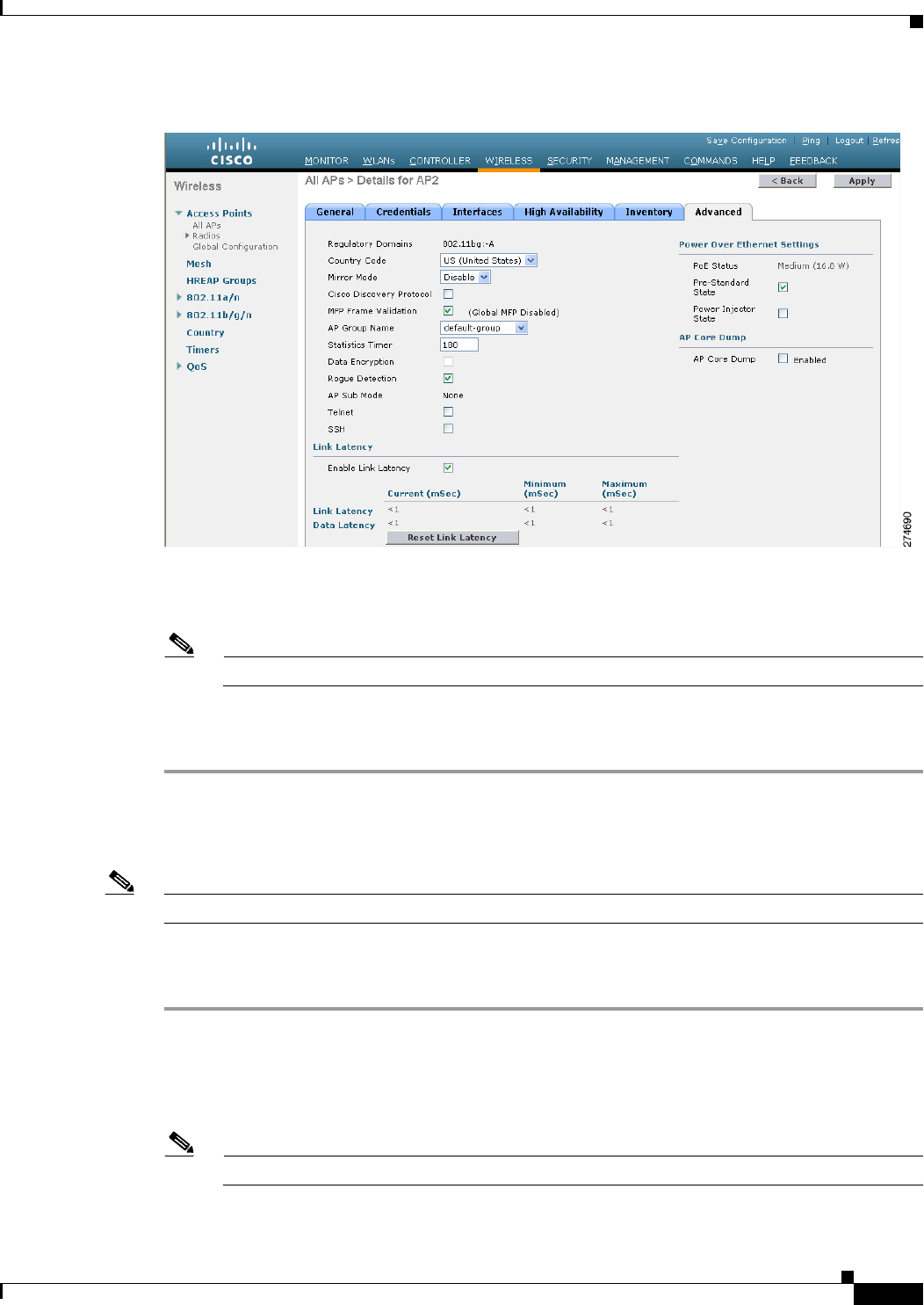
8-5
Cisco Wireless LAN Controller Configuration Guide
OL-21524-02
Chapter 8 Controlling Lightweight Access Points
Access Point Communication Protocols
Figure 8-1 All APs > Details for (Advanced) Page
Step 5 Select the Data Encryption check box to enable data encryption for this access point or unselect it to
disable this feature. The default value is unselected.
Note Changing the data encryption mode requires the access points to rejoin the controller.
Step 6 Click Apply to commit your changes.
Step 7 Click Save Configuration to save your changes.
Using the CLI to Configure Data Encryption
Note In images without a DTLS license, the config or show commands are not available.
To enable DTLS data encryption for access points on the controller using the controller CLI, follow these
steps:
Step 1 Enable or disable data encryption for all access points or a specific access point by entering this
command:
config ap link-encryption {enable | disable} {all | Cisco_AP}
The default value is disabled.
Note Changing the data encryption mode requires the access points to rejoin the controller.

8-6
Cisco Wireless LAN Controller Configuration Guide
OL-21524-02
Chapter 8 Controlling Lightweight Access Points
Access Point Communication Protocols
Step 2 When prompted to confirm that you want to disconnect the access point(s) and attached client(s), enter Y.
Step 3 Save your changes by entering this command:
save config
Step 4 See the encryption state of all access points or a specific access point by entering this command:
show ap link-encryption {all | Cisco_AP}
Information similar to the following appears:
Encryption Dnstream Upstream Last
AP Name State Count Count Update
-------------- ---------- -------- -------- --------
AP1130 En 112 1303 23:49
AP1140 En 232 2146 23:49
auth err: 198 replay err: 0
AP1250 En 0 0 Never
AP1240 En 6191 15011 22:13
This command also shows authentication errors, which tracks the number of integrity check failures, and
replay errors, which tracks the number of times that the access point receives the same packet.
Step 5 See a summary of all active DTLS connections by entering this command:
show dtls connections
Information similar to the following appears:
AP Name Local Port Peer IP Peer Port Ciphersuite
------------- ------------- ---------------- ------------- ----------------------------
AP1130 Capwap_Ctrl 172.20.225.163 62369 TLS_RSA_WITH_AES_128_CBC_SHA
AP1250 Capwap_Ctrl 172.20.225.166 19917 TLS_RSA_WITH_AES_128_CBC_SHA
AP1140 Capwap_Ctrl 172.20.225.165 1904 TLS_RSA_WITH_AES_128_CBC_SHA
AP1140 Capwap_Data 172.20.225.165 1904 TLS_RSA_WITH_AES_128_CBC_SHA
AP1130 Capwap_Data 172.20.225.163 62369 TLS_RSA_WITH_AES_128_CBC_SHA
AP1250 Capwap_Data 172.20.225.166 19917 TLS_RSA_WITH_AES_128_CBC_SHA
Note If you experience any problems with DTLS data encryption, enter the debug dtls {all | event |
trace | packet} {enable | disable} command to debug all DTLS messages, events, traces, or
packets.
Viewing CAPWAP MTU Information
See the maximum transmission unit (MTU) for the CAPWAP path on the controller by entering this
command:
show ap config general Cisco_AP
The MTU specifies the maximum size of any packet (in bytes) in a transmission.
Information similar to the following appears:
Cisco AP Identifier.............................. 9
Cisco AP Name.................................... Maria-1250
Country code..................................... US - United States
Regulatory Domain allowed by Country............. 802.11bg:-A 802.11a:-A
AP Country code.................................. US - United States
AP Regulatory Domain............................. 802.11bg:-A 802.11a:-A
Switch Port Number .............................. 1

8-7
Cisco Wireless LAN Controller Configuration Guide
OL-21524-02
Chapter 8 Controlling Lightweight Access Points
Access Point Communication Protocols
MAC Address...................................... 00:1f:ca:bd:bc:7c
IP Address Configuration......................... DHCP
IP Address....................................... 1.100.163.193
IP NetMask....................................... 255.255.255.0
CAPWAP Path MTU............................... 1485
...
Debugging CAPWAP
Use these CLI commands to obtain CAPWAP debug information:
• debug capwap events {enable | disable}—Enables or disables debugging of CAPWAP events.
• debug capwap errors {enable | disable}—Enables or disables debugging of CAPWAP errors.
• debug capwap detail {enable | disable}—Enables or disables debugging of CAPWAP details.
• debug capwap info {enable | disable}—Enables or disables debugging of CAPWAP information.
• debug capwap packet {enable | disable}—Enables or disables debugging of CAPWAP packets.
• debug capwap payload {enable | disable}—Enables or disables debugging of CAPWAP payloads.
• debug capwap hexdump {enable | disable}—Enables or disables debugging of the CAPWAP
hexadecimal dump.
• debug capwap dtls-keepalive {enable | disable}—Enables or disables debugging of CAPWAP
DTLS data keepalive packets.
Controller Discovery Process
In a CAPWAP environment, a lightweight access point discovers a controller by using CAPWAP
discovery mechanisms and then sends the controller a CAPWAP join request. The controller sends the
access point a CAPWAP join response allowing the access point to join the controller. When the access
point joins the controller, the controller manages its configuration, firmware, control transactions, and
data transactions.
Upgrade and downgrade paths from LWAPP to CAPWAP or from CAPWAP to LWAPP are supported.
An access point with an LWAPP image starts the discovery process in LWAPP. If it finds an LWAPP
controller, it starts the LWAPP discovery process to join the controller. If it does not find a LWAPP
controller, it starts the discovery in CAPWAP. If the number of times that the discovery process starts
with one discovery type (CAPWAP or LWAPP) exceeds the maximum discovery count and the access
point does not receive a discovery response, the discovery type changes to the other type. For example,
if the access point does not discover the controller in LWAPP, it starts the discovery process in CAPWAP.
Note If an access point is in the UP state and its IP address changes, the access point tears down the existing
CAPWAP tunnel and rejoins the controller. In previous software releases, the access point notifies the
controller, and the session continues with the changed IP address without tearing down the session.
Note You must install software release 4.0.155.0 or later releases on the controller before connecting 1100 and
1300 series access points to the controller. The 1120 and 1310 access points were not supported prior to
software release 4.0.155.0.

8-8
Cisco Wireless LAN Controller Configuration Guide
OL-21524-02
Chapter 8 Controlling Lightweight Access Points
Access Point Communication Protocols
Note During the discovery process, the 1140 and 3500 series access points will only query for Cisco CAPWAP
Controllers. It will not query for LWAPP controllers. If you want these access points to query for both
LWAPP and CAPWAP controllers then you need to update the DNS.
Note Make sure that the controller is set to the current time. If the controller is set to a time that has already
occurred, the access point might not join the controller because its certificate may not be valid for that
time.
Access points must be discovered by a controller before they can become an active part of the network.
The lightweight access points support these controller discovery processes:
• Layer 3 CAPWAP or LWAPP discovery—This feature can be enabled on different subnets from the
access point and uses IP addresses and UDP packets rather the MAC addresses used by Layer 2
discovery.
• Over-the-air provisioning (OTAP)—This feature is supported by Cisco 5500 and 4400 Series
Controllers. If this feature is enabled on the controller (on the controller General page or through
the config network otap-mode {enable | disable} CLI command), all associated access points
transmit wireless CAPWAP or LWAPP neighbor messages, and new access points receive the
controller IP address from these messages. This feature is disabled by default and should remain
disabled when all access points are installed.
Note Disabling OTAP on the controller does not disable it on the access point. OTAP cannot be
disabled on the access point.
Note You can find additional information about OTAP at this URL:
http://www.ciscosystems.com/en/US/products/ps6366/products_tech_note09186a008093d
74a.shtml
• Locally stored controller IP address discovery—If the access point was previously associated to a
controller, the IP addresses of the primary, secondary, and tertiary controllers are stored in the access
point’s nonvolatile memory. This process of storing controller IP addresses on an access point for
later deployment is called priming the access point.
• DHCP server discovery—This feature uses DHCP option 43 to provide controller IP addresses to
the access points. Cisco switches support a DHCP server option that is typically used for this
capability. For more information about DHCP option 43, see the “Using DHCP Option 43 and
DHCP Option 60” section on page 8-52.
• DNS discovery—The access point can discover controllers through your domain name server
(DNS). For the access point to do so, you must configure your DNS to return controller IP addresses
in response to CISCO-LWAPP-CONTROLLER.localdomain, where localdomain is the access point
domain name. When an access point receives an IP address and DNS information from a DHCP
server, it contacts the DNS to resolve CISCO-LWAPP-CONTROLLER.localdomain. When the DNS
sends a list of controller IP addresses, the access point sends discovery requests to the controllers.

8-9
Cisco Wireless LAN Controller Configuration Guide
OL-21524-02
Chapter 8 Controlling Lightweight Access Points
All APs
Verifying that Access Points Join the Controller
When replacing a controller, you need to make sure that access points join the new controller.
Using the GUI to Verify that Access Points Join the Controller
To ensure that access points join the new controller using the controller GUI, follow these steps:
Step 1 Configure the new controller as a master controller as follows:
a. Choose Controller > Advanced > Master Controller Mode to open the Master Controller
Configuration page.
b. Select the Master Controller Mode check box.
c. Click Apply to commit your changes.
d. Click Save Configuration to save your changes.
Step 2 (Optional) Flush the ARP and MAC address tables within the network infrastructure.
Step 3 Restart the access points.
Step 4 Once all the access points have joined the new controller, configure the controller not to be a master
controller by unselecting the Master Controller Mode check box on the Master Controller
Configuration page.
Using the CLI to Verify that Access Points Join the Controller
To ensure that access points join the new controller using the controller CLI, follow these steps:
Step 1 Configure the new controller as a master controller by entering this command:
config network master-base enable
Step 2 (Optional) Flush the ARP and MAC address tables within the network infrastructure.
Step 3 Restart the access points.
Step 4 Configure the controller not to be a master controller once all the access points have joined the new
controller by entering this command:
config network master-base disable
All APs
You can search for specific access points in the list of access points on the All APs page. To do so, you
create a filter to display only access points that meet certain criteria (such as MAC address, status, access
point mode, and certificate type). This feature is especially useful if your list of access points spans
multiple pages, preventing you from viewing them all at once.
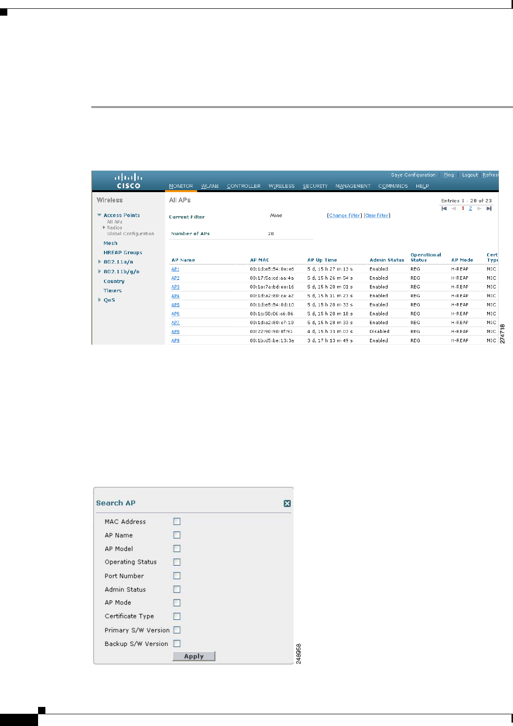
8-10
Cisco Wireless LAN Controller Configuration Guide
OL-21524-02
Chapter 8 Controlling Lightweight Access Points
All APs
Using the GUI to Search the AP Filter
To search for access points using the controller GUI, follow these steps:
Step 1 Choose Monitor > Access Point Summary> All APs > Details to open the All APs page (see
Figure 8-2).
Figure 8-2 All APs Page
This page lists all of the access points joined to the controller. For each access point, you can see its
name, MAC address, uptime, status, operating mode, certificates, OfficeExtend access point status, and
access point submode.
The total number of access points appears in the upper right-hand corner of the page. If the list of access
points spans multiple pages, you can access these pages by clicking the page number links. Each page
shows up to 20 access points.
Step 2 Click Change Filter to open the Search AP dialog box (see Figure 8-3).
Figure 8-3 Search AP Dialog Box

8-11
Cisco Wireless LAN Controller Configuration Guide
OL-21524-02
Chapter 8 Controlling Lightweight Access Points
All APs
Step 3 Select one or more of the following check boxes to specify the criteria used when displaying access
points:
• MAC Address—Enter the MAC address of an access point.
Note When you enable the MAC Address filter, the other filters are disabled automatically. When
you enable any of the other filters, the MAC Address filter is disabled automatically.
• AP Name—Enter the name of an access point.
• AP Model—Enter the model name of an access point.
• Operating Status—Select one or more of the following check boxes to specify the operating status
of the access points:
–
UP—The access point is up and running.
–
DOWN—The access point is not operational.
–
REG—The access point is registered to the controller.
–
DEREG—The access point is not registered to the controller.
–
DOWNLOAD—The controller is downloading its software image to the access point.
• Port Number—Enter the controller port number to which the access point is connected.
• Admin Status—Choose Enabled or Disabled to specify whether the access points are enabled or
disabled on the controller.
• AP Mode—Select one or more of the following options to specify the operating mode of the access
points:
–
Local—The default option.
Note The 600 OEAP series access point uses only local mode.
When an access point in local mode connects to a Cisco Flex 7500 Series Controller, it does not
serve clients. The access point details are available in the controller. To enable an access point
to serve clients or perform monitoring-related tasks when connected to the Cisco Flex 7500
Series Controller, the access point mode must be in hybrid-REAP or monitor mode. Use the
following command to automatically convert access points to a hybrid-REAP mode or monitor
mode on joining the controller:
config ap autoconvert {hreap | monitor | disable}
All access points that connect to the controller will either be converted to hybrid-REAP mode
or monitor mode depending on the configuration provided.
–
HREAP (hybrid Remote Edge lightweight Access Point)—This mode is used for 1040,
1130AG, 1140, 1240AG, 1250, 1260, 3500, AP801, and AP802 access points.
–
REAP—This mode is the remote edge lightweight access point.
–
Monitor—This mode is the monitor-only mode.
–
Rogue Detector—This mode monitors the rogue APs on wire. It does not transmit or receive
frames over the air or contain rogue APs.

8-12
Cisco Wireless LAN Controller Configuration Guide
OL-21524-02
Chapter 8 Controlling Lightweight Access Points
All APs
–
Sniffer—The access point starts sniffing the air on a given channel. It captures and forwards all
the packets from the clients on that channel to a remote machine that runs Airopeek or
Wireshark (packet analyzers for IEEE 802.11 wireless LANs). It includes information on the
time stamp, signal strength, packet size, and so on.
Note The Bridge option is displayed only if the AP is bridge capable.
Note If the AP mode is set to “Bridge” and the AP is not REAP capable, an error appears.
–
Bridge—This mode sets the AP mode to “Bridge” if you are connecting a Root AP.
–
SE-Connect—This mode allows you to connect to spectrum expert and it allows the access
point to perform spectrum intelligence.
Note The AP3500 supports the spectrum intelligence and AP1260 does not support the spectrum
intelligence.
Note When an access point is configured in SE-Connect mode, the access point reboots and rejoins
the controller. Access points that are configured in this mode do not serve the client.
• Certificate Type—Select one or more of the following check boxes to specify the types of
certificates installed on the access points:
–
MIC—Manufactured-installed certificate
–
SSC—Self-signed certificate
–
LSC—Local significant certificate
Note See the “Authorizing Access Points” section on page 8-45 for more information on these
certificate types.
• Primary S/W Version—Select this check box to enter the primary software version number
• Backup S/W Version—Select this check box to enter the secondary software version number.
Step 4 Click Apply to commit your changes. Only the access points that match your search criteria appear on
the All APs page, and the Current Filter parameter at the top of the page specifies the filter used to
generate the list (for example, MAC Address:00:1d:e5:54:0e:e6, AP Name:pmsk-ap, Operational Status:
UP, Status: Enabled, and so on).
Note If you want to remove the filters and display the entire access point list, click Clear Filter.

8-13
Cisco Wireless LAN Controller Configuration Guide
OL-21524-02
Chapter 8 Controlling Lightweight Access Points
All APs > Details
All APs > Details
Choose WIRELESS > Access Points > All APs and then click an AP name to navigate to this page.
This page shows the details of the selected access point including the hardware, operating system, and
boot version details.
General Tab
Table 8-1 describes the parameters that are listed under the General Tab.
Ta b l e 8-1 General Tab Parameters
Paramter Description
AP Name User-definable name of the access point.
Location User-definable location name for the access point.
AP MAC Address MAC address of the access point.
Base Radio MAC MAC address of the 802.11a/b/g/n radio.
Status Administration state of the access point: enabled or disabled.

8-14
Cisco Wireless LAN Controller Configuration Guide
OL-21524-02
Chapter 8 Controlling Lightweight Access Points
All APs > Details
AP Mode Access point mode of operation. The options are as follows:
• Local—Specifies the default option.
Note The 600 OEAP series access points uses only local mode.
When an access point in local mode connects to a Cisco Flex 7500 Series
Controller, it does not serve clients. The access point details are available
in the controller. To enable an access point to serve clients or perform
monitoring-related tasks when connected to the Cisco Flex 7500 Series
Controller, the access point mode must be in hybrid-REAP or monitor
mode.
All access points that connect to the controller will either be converted to
hybrid-REAP mode or monitor mode depending on the configuration
provided.
• H-REAP (hybrid Remote Edge lightweight Access Point)—Specifies the
1040, 1130AG, 1140, 1240AG, 1250, 1260, 3500, AP801, and AP802
access points.
• Monitor—Specifies the monitor-only mode.
• Rogue Detector—This mode monitors the rogue APs on wire. It does not
transmit or receive frames over the air or contain rogue APs.
• Sniffer—Specifies the access point that starts sniffing the air on a given
channel. It captures and forwards all the packets from the clients on that
channel to a remote machine that runs Airopeek or Wireshark (packet
analyzers for IEEE 802.11 wireless LANs). It will include information on
time stamps, signal strength, packet sizes and so on.
Note The Bridge option is displayed only if the AP is bridge capable.
Note If the AP mode is set to “Bridge” and the AP is not REAP capable, an
error appears.
• Bridge—Sets the AP mode to “Bridge” if you are connecting a Root AP.
Note The SE-Connect option is displayed only if the AP is CleanAir capable.
Note When an access point is configured in SE-Connect mode, the access
point will reboot and rejoin the controller. Access points that are
configured in this mode do not serve clients.
• SE-Connect—Sets the AP mode to SE-Connect if you want the access point
to perform spectrum intelligence.
AP Sub Mode Displays wIPS if the access point in is Monitor, Local, or H-REAP modes and
the wIPS submode is configured on the access point or None if the access point
is not in Monitor mode or the access point is in Monitor mode but the wIPS
submode is not configured.
Operational Status Operational status of the access point that comes up as either registered (REG)
or not registered (DEREG) automatically by the controller.
Port Number Access point that is connected to this controller port.
Table 8-1 General Tab Parameters (continued)
Paramter Description

8-15
Cisco Wireless LAN Controller Configuration Guide
OL-21524-02
Chapter 8 Controlling Lightweight Access Points
All APs > Details
Versions Tab
Table 8-2 describes the parameters that are listed under the Versions Tab.
Ta b l e 8-2 Versions Ta b P a r a m e t e r s
Parameters Description
Primary Software
Vers i o n
Primary software version.
Backup Software
Vers i o n
Version of the backup software on this access point.
Predownload Status Predownload status on this access point.
Predownloaded
Vers i o n
Version of the software that is being predownloaded.
Predownload Next
Retry time
Time duration after which this access point will try to perform a predownload
operation.
Predownload Retry
Count
Count of the number of times this access point has tried to perform the
predownload operation.
Boot Version Boot ROM versions.
IOS Version Cisco IOS Software version.
Mini IOS Version Mini-IOS software version.

8-16
Cisco Wireless LAN Controller Configuration Guide
OL-21524-02
Chapter 8 Controlling Lightweight Access Points
All APs > Details
Table 8-3 lists the IP configuration parameters.
Ta b l e 8-3 IP Config Parameters
Parameter Description
IP Address IP address of the access point.
Static IP Static IP address of the access point.
When an access point boots up, it tries to determine if its static IP address is
configured or not. If an access point has been configured with a static IP address
that is not valid on the network, the access point cannot join the controller and
cannot communicate with the rest of the network. The only way to recover that
access point is to manually open the access point door and connect a serial
console for configuration purpose.
The access point can be configured in such a way that even if its static IP
address is not valid on the network, it initiates a DHCP process to get a new IP
address and uses it for communication. This situation allows the access point to
join the controllers on the network.
Note An access point cannot discover the controller using domain name
system (DNS) resolution if a static IP address is configured for the
access point, unless you specify a DNS server and the domain to which
the access point belongs.
Options for this parameter are as follows:
• Unselected—When the box is unselected, the static IP address is disabled
and the access point initiates a DHCP process when it boots up to procure
the IP address.
• Selected—When the box is selected, you can set the following:
–
The static IP address of the access point.
–
The subnet mask assigned to the access point IP address.
–
The gateway of the access point.
Click Apply to commit your changes. The access point reboots and rejoins
the controller, and the static IP address that you specified is sent to the
access point. You can now configure the DNS server IP address and domain
name. To do so, follow these steps:
–
In the DNS IP Address text box, enter the IP address of the DNS server.
–
In the Domain Name text box, enter the name of the domain to which
the access point belongs.
Click Apply to commit your changes.

8-17
Cisco Wireless LAN Controller Configuration Guide
OL-21524-02
Chapter 8 Controlling Lightweight Access Points
All APs > Details
Table 8-4 lists the time statistics parameters.
Table 8-5 lists the hardware reset parameters.
Table 8-6 lists the set to factory defaults parameters.
Credentials Tab
Table 8-7 lists the login parameters under the Credentials Tab.
Ta b l e 8-4 Time Statistics Parameters
Parameters Description
UP Time Amount of time that the access point has been powered up.
Controller
Associated Time
Amount of time that the access point has been associated with the controller.
Controller
Associated Latency
Amount of time that the access point took to associate with the controller.
Ta b l e 8-5 Hardware Reset
Button Description
Reset AP Now Button that resets the access point.
Ta b l e 8-6 Set to Factory Defaults
Button Description
Clear All Config Button that resets the access point parameters to the factory-defaults.
Note The clear all configuration action does not affect OEAP 600 Series
Access Point. The only way to reset the access point to factory defaults
is by pressing the reset button on the access point and then power
cycling the AP.
Clear Config Except
Static IP
Button that resets the access point parameters to the factory defaults but retains
the static IP address information.
Ta b l e 8-7 Login Credentials
Parameter Description
Over-ride Global
credentials
Credentials that prevent this access point from inheriting the global username,
password, and enable password from the controller. The default value is
unselected.
Note The Username, Password, and Enable Password text boxes appears only
when you select the Over-ride Global credentials check box.
Username Unique username for this access point.
Password Unique password for this access point.
Enable Password Unique enable password for this access point.

8-18
Cisco Wireless LAN Controller Configuration Guide
OL-21524-02
Chapter 8 Controlling Lightweight Access Points
All APs > Details
Table 8-8 lists the 802.1X supplicant credentials parameters.
Interfaces Tab
Note Ethernet Interfaces statistics are displayed only for mesh or bridged access points; statistics are not
displayed for nonmesh access points.
Table 8-9 lists the Ethernet interfaces parameters.
Ta b l e 8-8 802.1X Supplicant Credentials
Parameter Description
Over-ride Global
credentials
Credentials that prevent this access point from inheriting the global
authentication username and password from the controller. The default value is
unselected.
Note The Username, Password, and Confirm Password text boxes are
displayed only when you select the Over-ride Global credentials check
box.
Username Unique username for this access point.
Password Unique password for this access point.
Note You must enter a strong password. Strong passwords have the following
characteristics:
• They are at least eight characters long.
• They contain a combination of uppercase and lowercase letters,
numbers, and symbols.
• They are not a word in any language.
Confirm Password Action to reenter the unique password for this access point.
Ta b l e 8-9 Ethernet Interfaces
Parameter Description
Interface Interface name.
Operational Status Status of the interface.
Tx Unicast Packets Number of unicast packets transmitted.
Rx Unicast Packets Number of unicast packets received.
Tx Non-Unicast
Packets
Number of nonunicast packets transmitted.
Rx Non-Unicast
Packets
Number of nonunicast packets received.

8-19
Cisco Wireless LAN Controller Configuration Guide
OL-21524-02
Chapter 8 Controlling Lightweight Access Points
All APs > Details
Table 8-10 lists the interface properties parameters.
Ta b l e 8-10 Interface Properties Parameters
Parameter Description
AP Name Name of the access point.
Link Speed Speed of the interference in Mbps.
RX Bytes Total number of bytes in the error-free packets received on the interface.
RX Unicast Packets Total number of unicast packets received on the interface.
RX Non-Unicast
Packets
Total number of nonunicast or multicast packets received on the interface.
Input CRC Total number of CRC error in packets while receiving on the interface.
Input Errors Sum of all errors in the packets while receiving on the interface.
Input Overrun Number of times the receiver hardware was incapable of handling received data
to a hardware buffer because the input rate exceeded the receiver’s capability to
handle the data.
Input Resource Total number of resource errors in packets received on the interface.
Runts Number of packets that are discarded because they are similar than the
medium’s minimum packet size.
Throttle Total number of times the interface advised a sending NIC that it was
overwhelmed by packets being sent and to slow the pace of delivery.
Output Collision Total number of packet retransmitted due to an Ethernet collision.
Output Resource Resource errors in packets transmitted on the interface.
Output Errors Errors that prevented the final transmission of packets out of the interface.
Operational Status Operational state of the physical ethernet interface on the AP.
Duplex Interface’s duplex mode.
TX Bytes Number of bytes in the error-free packets transmitted on the interface.
TX Unicast Packets Total number of unicast packets transmitted on the interface.
TX Non-Unicast
Packets
Total number of nonunicast or multicast packets transmitted on the interface.
Input Aborts Total number of packets aborted while receiving on the interface.
Input Frames Total number of packets received incorrectly that has a CRD error and a
noninteger number of octets on the interface.
Input Drops Total number of packets dropped while receiving on the interface because the
queue was full.
Unknown Protocol Total number of packets discarded on the interface due to an unknown protocol.
Giants Number of packets that are discarded because they exceeded the medium’s
maximum packet size.
Interface Resets Number of times that an interface has been completely reset.
Output No Buffer Total number of packets discarded because there was no buffer space.

8-20
Cisco Wireless LAN Controller Configuration Guide
OL-21524-02
Chapter 8 Controlling Lightweight Access Points
All APs > Details
Table 8-11 lists the radio interface parameters.
High Availability Tab
Note Entering an IP address for the backup controller is optional. If the backup controller is outside the
mobility group to which the access point is connected (the primary controller), then you need to provide
the IP address of the primary, secondary, or tertiary controller, respectively. The controller name and IP
address must belong to the same primary, secondary, or tertiary controller. Otherwise, the access point
cannot join the backup controller.
Table 8-12 lists the high availability tab parameters.
Output Underrun Number of times the transmitter has been running faster than the router can
handle.
Outout Total Drops Total number of packets dropped while transmitting from the interface because
the queue was full.
Table 8-10 Interface Properties Parameters (continued)
Parameter Description
Ta b l e 8-11 Radio Interfaces
Parameter Description
Number of Radio
interfaces
Number of radio interfaces.
Radio Slot# Slot where the radio is installed.
Radio Interface Type Cisco Radio type: 802.11a/n or 802.11b/g/n.
Sub Band Cisco Radio sub band, if it is active: 4.9 GHz or 5 GHz.
Admin Status Cisco Radio interface status: enabled or disabled.
Oper Status Cisco Radio operational status: UP or DOWN.
CleanAir admin
Status
CleanAir admin status.
CleanAir oper status CleanAir operator status.
Regulatory Domain Whether the domain is supported or unsupported.
Ta b l e 8-12 High Availability Tab Parameters
Parameter Description
Primary Controller Name and management IP address of the primary controller.
Secondary
Controller
Name and management IP address of the secondary controller.

8-21
Cisco Wireless LAN Controller Configuration Guide
OL-21524-02
Chapter 8 Controlling Lightweight Access Points
All APs > Details
Inventory Tab
Table 8-13 lists the inventory tab parameters.
Tertiary Controller Name and management IP address of the tertiary controller.
AP Failover Priority Priority for the access point:
• Low—Assigns the access point to the level 1 priority, which is the lowest
priority level. This is the default value.
• Medium—Assigns the access point to the level 2 priority.
• High—Assigns the access point to the level 3 priority.
• Critical—Assigns the access point to the level 4 priority, which is the
highest priority level.
Table 8-12 High Availability Tab Parameters (continued)
Parameter Description
Ta b l e 8-13 Inventory Tab Parameters
Parameter Description
Product ID Model of the access point.
Vers i o n I D Version of the access point.
Serial Number Access point’s serial number, for example, FTX0916T134.
Entity Name Access point’s entity name.
Entity Description Access point’s entity description.
Certificate Type Certificate type: Self Signed or Manufacture Installed.
H-REAP Mode
Supported
Whether the access point can be configured as a remote edge lightweight access
point: Yes or No.
H-REAP Mode is supported on the 1130AG, 1140, 1240AG, 1250, 1260, 3500,
AP801, and AP802 access points.
Note By default, VLAN is not enabled on the H-REAP. After it is enabled,
H-REAP inherits the VLAN name (interface name) and VLAN-ID
associated to WLANs. This configuration is saved in the access point
and received after the successful join response. By default, no VLAN is
set as a native VLAN. There must be one native VLAN configured per
REAP in a VLAN enabled domain. Otherwise, REAP cannot send
packets to or receive packets from the controller. When the client gets
assigned a VLAN from the RADIUS server for the client, that VLAN is
associated to the local switched WLAN.
Note Black list—H-REAP supports the first 128 entries in the list in the
standalone mode.

8-22
Cisco Wireless LAN Controller Configuration Guide
OL-21524-02
Chapter 8 Controlling Lightweight Access Points
All APs > Details
Mesh Tab
Note This tab appears if you set the AP Mode on the General Tab to Bridge.
Table 8-14 lists the mesh tab parameters.
Ta b l e 8-14 Mesh Tab
Parameter Description
AP Role Root AP or Mesh AP.
Root APs have a wired CAPWAP (Control and Provisioning of Wireless Access
Points) protocol connection back to a Cisco controller. This connection uses the
backhaul wireless interface to communicate to neighboring Mesh APs. Root
APs are the parent node to any bridging or mesh network and connect a bridge
or mesh network to the wired network. Only one Root AP can be on for any
bridged or mesh network.
Mesh APs have no wired connection to a Cisco controller. They can be
completely wireless supporting clients, communicating to other Mesh APs and
a Root AP to get access to the network, or they can be wired and serve as bridge
to a remote wired network.
Bridge Type Display only. Whether the access point is an indoor or outdoor access point.
Bridge Group Name Bridge group name.
Use bridge group names to logically group the access points and avoid two
networks on the same channel from communicating with each other.
Note For the access points to communicate with each other, they must have
the same bridge group name.
Ethernet Bridging Ethernet bridging on the access point.
If the AP Mode is Root AP, Ethernet bridging is enabled by default.
If the AP Mode is Mesh AP, Ethernet bridging is disabled by default.
Enable Ethernet bridging on a Mesh AP if you want to do the following:
• Use the mesh nodes as bridges.
• Connect an Ethernet device on the Mesh AP using its Ethernet port.
Note When you enable Ethernet Bridging and click Apply, the
Table 8-15Ethernet Bridging Parameters area appears and lists the four
Ethernet ports of the mesh access point.
Backhaul Interface Display only. Backhaul interface (802.11a, 802.11b or 802.11g).

8-23
Cisco Wireless LAN Controller Configuration Guide
OL-21524-02
Chapter 8 Controlling Lightweight Access Points
All APs > Details
Table 8-15 lists the Enternet bridging parameters.
Note The following information appears when you enable Ethernet Bridging and click Apply.
Bridge Data Rate
(Mbps)
Data rate. This is the rate at which data is shared between the access points. The
drop-down list displays the data rates depending on the Backhaul Interface set.
The correct range of values depend on the backhaul interfaces used by the
access points.
The data rates (Mbps) are as follows:
• 802.11a—auto, 6, 9, 12, 18, 24, 36, 48, 54
Note In previous software releases, the default value for bridge data rate for
802.11a was 24 Mbps. In controller software release 6.0, the default
value for bridge data rate is auto. If you configured the default bridge
data rate value (24 Mbps) in a previous controller software release, the
bridge data rate is configured with the new default value (auto) when
you upgrade to controller software release 6.0. However, if you
configured a non-default value (for example, 18 Mbps) in a previous
controller software release, that configuration setting is preserved when
you upgrade to software release 6.0.
When the bridge data rate is set to auto, the mesh backhaul chooses the
highest rate where the next higher rate cannot be used due to unsuitable
conditions for that specific rate (and not because of conditions that
affect all rates).
• 802.11b—1, 2, 5.5, 11
• 802.11g—1, 2, 5.5, 11, 6, 9, 12, 18, 24, 36, 48, 54
Ethernet Link Status Status of the Ethernet (LAP1510) or Gigabit Ethernet (LAP1522) links. For
each link, the status can be Up, Dn, or Na.
Heater Status Status of the heater: ON or OFF.
Internal Temperature Internal temperature of the access point in Fahrenheit and Celsius.
Table 8-14 Mesh Tab (continued)
Parameter Description
Ta b l e 8-15 Ethernet Bridging Parameters
Parameter Description
Interface Name Name of the interface. Click the interface name to open the All APs > ap_name
> VLAN Mappings (for mesh access points) page.
To configure the access mode on a Mesh access point, click the
gigabitEthernet1 interface.
To configure the trunk mode on a Root or Mesh access point, click the
gigabitEthernet0 interface.
Oper Status Operational status of the interface.

8-24
Cisco Wireless LAN Controller Configuration Guide
OL-21524-02
Chapter 8 Controlling Lightweight Access Points
All APs > Details
H-REAP Tab
Note This tab appears if you set the AP Mode on the General Tab to H-REAP.
Table 8-16 lists the H-REAP tab parameters.
Mode Mode of the interface: Normal, Access, or Trunk.
VLAN ID VLAN ID of the interface.
Table 8-15 Ethernet Bridging Parameters (continued)
Parameter Description
Ta b l e 8-16 H-REAP Tab Parameters
Parameter Description
VLAN Support Native VLAN ID.
Note After you enable VLAN support, click Apply to activate the VLAN
Mappings button.
Native VLAN ID VLAN ID number.
VLAN Mappings All APs > ap_name > VLAN Mappings (for H-REAP Access Points) page.
HREAP Group
Name
Name of the group if the access point belongs to a hybrid-REAP group.
OfficeExtend AP
Note Currently, Cisco 1040, 1130, 1140, and 3502I series access points that are joined to a Cisco
5500 Series Controller can be configured to operate as OfficeExtend access points.
Enable OfficeExtend
AP
Mode that you can enable for this access point. The default value is enabled.
Note Unselecting this check box disables OfficeExtend mode for this access
point. It does not undo all of the configuration settings on the access
point.
Enable Least
Latency Controller
Join
Mode that you can enable for the access point to choose the controller with the
least latency when joining. The default value is disabled.
When you enable this feature, the access point calculates the time between the
discovery request and discovery response and joins the Cisco 5500 Series
Controller that responds first.
Reset Personal SSID Mode that allows you to clear only the access point’s personal SSID.
Note If you want to clear the access point’s configuration and return it to
factory-default settings, enter the clear ap config Cisco_AP command
on the controller CLI.

8-25
Cisco Wireless LAN Controller Configuration Guide
OL-21524-02
Chapter 8 Controlling Lightweight Access Points
All APs > Details
Advanced Tab
Table 8-17 lists the advanced tab parameters.
Ta b l e 8-17 Advanced Tab Parameters
Parameter Description
Regulatory Domains Regulatory domain of the AP.
Country Code Country code.
Mirror Mode Port Mirroring mode: enabled or disabled.
Cisco Discovery
Protocol
Cisco Discovery Protocol.
MFP Frame
Validation
Infrastructure Management Frame Protection validation that causes the AP to
authenticate all AP-originating frames that are detected on the radio frequency
in which it is operating. If Infrastructure MFP is not enabled globally, a “Global
MFP Disabled” message appears next to the check box, and management frames
are not validated.
See the Using the GUI to Configure MFP page for information on enabling MFP
globally on the controller.
AP Group Name Drop-down list that contains the names of AP Group VLANs that you have
created.
To associate an AP group VLAN with an access point, follow these steps:
1. Choose an AP group VLAN from the drop-down list.
2. Click Apply.
For more information on creating a new AP Group and mapping it to an
interface, see the “Configuring Access Point Groups” section on page 7-55.
Statistics Timer Counter that sets the time in seconds that the access point sends its DOT11
statistics to the controller.

8-26
Cisco Wireless LAN Controller Configuration Guide
OL-21524-02
Chapter 8 Controlling Lightweight Access Points
All APs > Details
Data Encryption Datagram Transport Layer Security (DTLS) data encryption.
Cisco 5500 Series Controllers allow you to encrypt CAPWAP control packets
(and optionally, CAPWAP data packets) that are sent between the access point
and the controller using Datagram Transport Layer Security (DTLS). DTLS is a
standards-track Internet Engineering Task Force (IETF) protocol based on TLS.
CAPWAP control packets are management packets exchanged between a
controller and an access point while CAPWAP data packets encapsulate
forwarded wireless frames. CAPWAP control and data packets are sent over
separate UDP ports: 5246 (control) and 5247 (data). If an access point does not
support DTLS data encryption, DTLS is enabled only for the control plane, and
a DTLS session for the data plane is not established.
Note Only Cisco 5500 Series Controllers support DTLS data encryption. This
feature is not available on other controller platforms. If an access point
with data encryption enabled tries to join any other controller, the access
point joins the controller, but data packets are sent unencrypted.
Note Only 1040, 1130, 1140, 1240, 1250, 1260, and 3500 series access points
support DTLS data encryption, and data-encrypted access points can
join a Cisco 5500 Series Controller only if the base license is installed
on the controller.
DTLS data encryption is enabled automatically for OfficeExtend access points
but disabled by default for all other access points. Most access points are
deployed in a secure network within a company building, so data encryption is
not necessary. In contrast, the traffic between an OfficeExtend access point and
the controller travels through an unsecure public network, so data encryption is
more important for these access points. When data encryption is enabled, traffic
is encrypted at the access point before it is sent to the controller and at the
controller before it is sent to the client.
Note Encryption limits throughput at both the controller and the access point,
and maximum throughput is desired for most enterprise networks.
Rogue Detection Rogue detection that you can enable or disable for individual access points.
Rogue detection is enabled by default for all access points joined to the
controller (except for OfficeExtend access points).
Telnet Telnet or SSH connectivity on this access point. The default values are
unselected.
SSH Protocol that makes debugging the access point easier, especially when the
access point is unable to connect to the controller.
TCP Adjust MSS TCP adjust Maximum Segment Size. The range is 536 to 1336.
Enable Link Latency Enable link latency feature for this access point.
Enable link latency is used to measure the link between an access point and the
controller. This feature can be used with all access points joined to the controller
but is especially useful for hybrid-REAP access points (in connected mode) and
OfficeExtend access points, for which the link could be a slow or unreliable
WAN connection.
Note Hybrid-REAP access points in standalone mode are not supported.
Table 8-17 Advanced Tab Parameters (continued)
Parameter Description

8-27
Cisco Wireless LAN Controller Configuration Guide
OL-21524-02
Chapter 8 Controlling Lightweight Access Points
All APs > Details
Current (mSec) Current round-trip time (in milliseconds) of CAPWAP heartbeat packets from
the access point to the controller and back.
Minimum (mSec) Minimum round-trip time (in milliseconds) of CAPWAP heartbeat packets from
the access point to the controller and back since link latency has been enabled
or reset.
Maximum (mSec) Maximum round-trip time (in milliseconds) of CAPWAP heartbeat packets from
the access point to the controller and back since link latency has been enabled
or reset.
Reset Link Latency Feature that clears all link latency statistics on the controller for this access
point.
AP Image Download
Perform a primary
image pre-download
for this AP
Download Primary button that you click to perform a primary image
predownload for this access point.
An alert box appears displaying the version that is downloaded when the access
point boots. Click OK to continue.
Perform a
interchange of both
the images on this
AP
Interchange Image button that you click to swap the images on this access point.
An alert box appears prompting you to confirm if you want to interchange the
images. Click OK to continue.
Perform a backup
image pre-download
for this AP
Download Backup button that you click to predownload a backup image for this
access point.
An alert box appears displaying the version that is downloaded when the access
point boots. Click OK to continue.
PoE Status Text box that applies only to 1250 series access points that are powered using
PoE.
THe PoE Status text box shows the power level at which the access point is
operating: High (20 W), Medium (16.8 W), or Medium (15.4 W). This text box
is not configurable. The controller auto-detects the access point’s power source
and displays the power level here.
Note There are two other ways to tell if the access point is operating at a lower
power level. First, the “Due to low PoE, radio is transmitting at degraded
power” message appears under the Tx Power Level Assignment area on
the 802.11 a/n APs > Configure page. Second, the “PoE Status: degraded
operation” message appears in the controller’s trap log on the Trap Logs
page.
Pre-standard 802.3af
switches
Whether the access point is being powered by a high-power 802.3af Cisco
switch or a power injector.
This option is disabled by default.
Power Injector State Whether the attached switch does not support intelligent power management
(IPM) and a power injector is being used. If the attached switch supports IPM,
you do not need to select this check box.
Table 8-17 Advanced Tab Parameters (continued)
Parameter Description

8-28
Cisco Wireless LAN Controller Configuration Guide
OL-21524-02
Chapter 8 Controlling Lightweight Access Points
Using the GUI to Monitor the Interface Details
Using the GUI to Monitor the Interface Details
To monitor the interface details using the controller GUI, follow these steps:
Step 1 Choose Monitor > Summary > All APs. The All APs > Details page appears.
Step 2 Click the Interfaces tab. The Interfaces tab is shown in Figure 8-4.
Power Injector
Selection
Power injector selection options are as follows:
• Installed—Allows the access point to examine and remember the MAC
address of the currently connected switch port and assumes that a power
injector is connected.
If you want to configure the switch MAC address, enter the MAC address in
the Injector Switch MAC Address text box.
• Override—Allows the access point to operate in high-power mode without
first verifying a matching MAC address.
Power Over Ethernet Settings
Injector Switch
MAC Address
MAC address of the connected switch port.
AP Core Dump Settings
AP Core Dump Upload of the access point core dump.
TFTP Server IP IP address of the TFTP server.
File name Name for the access point core dump file (for example, dump.log).
File Compression File compression of the access point core dump file. When you enable this
option, the file is saved with a .gz extension (for example, dump.log.gz). This
file can be opened with WinZip.
Table 8-17 Advanced Tab Parameters (continued)
Parameter Description
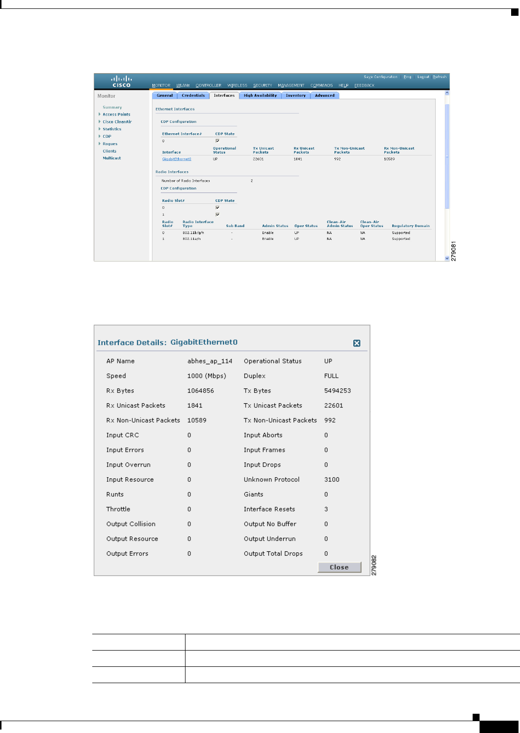
8-29
Cisco Wireless LAN Controller Configuration Guide
OL-21524-02
Chapter 8 Controlling Lightweight Access Points
Using the GUI to Monitor the Interface Details
Figure 8-4 Interfaces Tab
Step 3 Click on the available Interface name. The Interface Details page appears. See Figure 8-5.
Figure 8-5 Interfaces Details Page
Step 4 The Interface Details page displays the following parameter details. See Table 8-18.
Ta b l e 8-18 Interfaces Parameters Details
Button Description
AP Name Name of the access point.
Link Speed Speed of the interference in Mbps.

8-30
Cisco Wireless LAN Controller Configuration Guide
OL-21524-02
Chapter 8 Controlling Lightweight Access Points
Using the GUI to Monitor the Interface Details
RX Bytes Total number of bytes in the error-free packets received on the interface.
RX Unicast Packets Total number of unicast packets received on the interface.
RX Non-Unicast
Packets
Total number of nonunicast or multicast packets received on the interface.
Input CRC Total number of CRC error in packets while receiving on the interface.
Input Errors Sum of all errors in the packets while receiving on the interface.
Input Overrun Number of times the receiver hardware was incapable of handling received data
to a hardware buffer because the input rate exceeded the receiver’s capability to
handle that data.
Input Resource Total number of resource errors in packets received on the interface.
Runts Number of packets that are discarded because they are similar to the medium’s
minimum packet size.
Throttle Total number of times the interface advised a sending NIC that it was
overwhelmed by packets being sent and to slow the pace of delivery.
Output Collision Total number of packet retransmitted due to an Ethernet collision.
Output Resource Resource errors in packets transmitted on the interface.
Output Errors Errors that prevented the final transmission of packets out of the interface.
Operational Status Operational state of the physical ethernet interface on the AP.
Duplex Interface’s duplex mode.
TX Bytes Number of bytes in the error-free packets transmitted on the interface.
TX Unicast Packets Total number of unicast packets transmitted on the interface.
TX Non-Unicast
Packets
Total number of nonunicast or multicast packets transmitted on the interface.
Input Aborts Total number of packets aborted while receiving on the interface.
Input Frames Total number of packets received incorrectly that has a CRC error and a
noninteger number of octets on the interface.
Input Drops Total number of packets dropped while receiving on the interface because the
queue was full.
Unknown Protocol Total number of packets discarded on the interface due to an unknown protocol.
Giants Number of packets that are discarded because they exceeded the medium’s
maximum packet size.
Interface Resets Number of times that an interface has been completely reset.
Output No Buffer Total number of packets discarded because there was no buffer space.
Output Underrun Number of times the transmitter has been running faster than the router can
handle.
Outout Total Drops Total number of packets dropped while transmitting from the interface because
the queue was full.
Table 8-18 Interfaces Parameters Details (continued)
Button Description
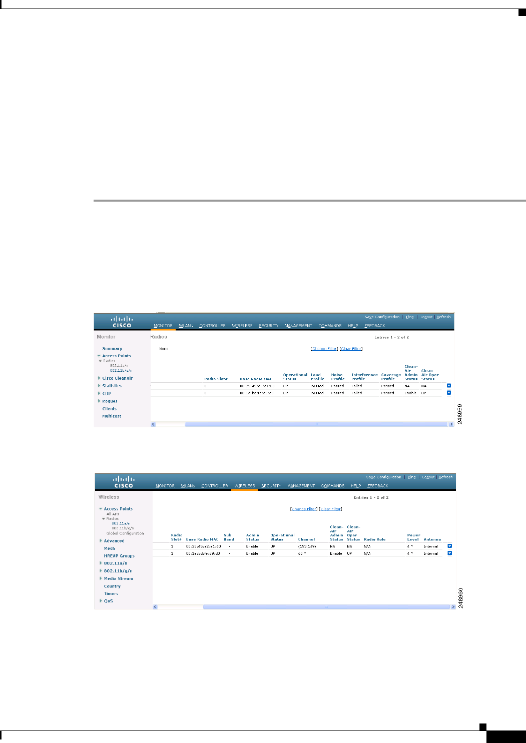
8-31
Cisco Wireless LAN Controller Configuration Guide
OL-21524-02
Chapter 8 Controlling Lightweight Access Points
Using the GUI to Search Access Point Radios
Using the GUI to Search Access Point Radios
You can search for specific access point radios in the list of radios on the 802.11a/n Radios page or the
802.11b/g/n Radios page. You can access these pages from the Monitor tab on the menu bar when
viewing access point radios or from the Wireless tab on the menu bar when configuring access point
radios. To search for specific access point radios, you create a filter to display only radios that meet
certain criteria (such as radio MAC address, access point name, or CleanAir status). This feature is
especially useful if your list of access point radios spans multiple pages, which prevents you from
viewing them all at once.
To search for access point radios using the controller GUI, follow these steps:
Step 1 Perform one of the following:
• Choose Monitor > Access Points Summary> 802.11a/n (or 802.11b/g/n) Radios > Details to open
the 802.11a/n (or 802.11b/g/n) Radios page (see Figure 8-6).
• Choose Wireless > Access Points > Radios > 802.11a/n (or 802.11b/g/n) to open the 802.11a/n (or
802.11b/g/n) Radios page (see Figure 8-7).
Figure 8-6 802.11a/n Radios Page (from the Monitor Tab)
Figure 8-7 802.11a/n Radios Page (from the Wireless Tab)
These pages show all of the 802.11a/n or 802.11b/g/n access point radios that are joined to the controller
and their current settings.
The total number of access point radios appears in the upper right-hand corner of the page. If the list of
radios spans multiple pages, you can access these pages by clicking the page number links. Each page
shows up to 25 access point radios.
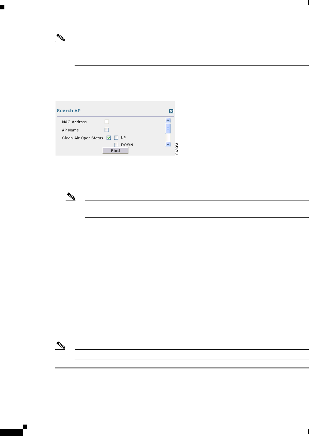
8-32
Cisco Wireless LAN Controller Configuration Guide
OL-21524-02
Chapter 8 Controlling Lightweight Access Points
Using the GUI to Search Access Point Radios
Note In a Cisco Unified Wireless Network environment, the 802.11a and 802.11b/g radios should not
be differentiated based on their Base Radio MAC addresses, as they may have the same
addresses. Instead, the radios should be differentiated based on their physical addresses.
Step 2 Click Change Filter to open the Search AP dialog box (see Figure 8-8).
Figure 8-8 Search AP Dialog Box
Step 3 Select one of the following check boxes to specify the criteria used when displaying access point radios:
• MAC Address—Enter the base radio MAC address of an access point radio.
• AP Name—Enter the name of an access point.
Note When you enable the MAC address filter, the other filters are disabled automatically. When
you enable any of the other filters, the MAC address filter is disabled automatically.
• CleanAir Status—Select one or more of the following check boxes to specify the operating status
of the access points:
–
UP—The spectrum sensor for the access point radio is currently operational.
–
DOWN—The spectrum sensor for the access point radio is currently not operational because an
error has occurred. The most likely reason for the error is that the access point radio is disabled.
–
ERROR—The spectrum sensor for the access point radio has crashed, making CleanAir
monitoring nonoperational for this radio. We recommend rebooting the access point or
disabling CleanAir functionality on the radio.
–
N/A—The access point radio is not capable of supporting CleanAir functionality. Currently,
only Cisco Aironet 3500 series access point radios can be configured for Cisco CleanAir.
Step 4 Click Find to commit your changes. Only the access point radios that match your search criteria appear
on the 802.11a/n Radios page or the 802.11b/g/n Radios page, and the Current Filter parameter at the
top of the page specifies the filter used to generate the list (for example, MAC Address:00:1e:f7:75:0a:a0
or AP Name:pmsk-ap).
Note If you want to remove the filter and display the entire access point radio list, click Clear Filter.

8-33
Cisco Wireless LAN Controller Configuration Guide
OL-21524-02
Chapter 8 Controlling Lightweight Access Points
Configuring Global Credentials for Access Points
Configuring Global Credentials for Access Points
Cisco IOS access points are shipped from the factory with Cisco as the default enable password. This
password allows users to log into the nonprivileged mode and execute show and debug commands,
posing a security threat. The default enable password must be changed to prevent unauthorized access
and to enable users to execute configuration commands from the access point’s console port.
In controller software releases prior to 5.0, you can set the access point enable password only for access
points that are currently connected to the controller. In controller software release 5.0 or later releases,
you can set a global username, password, and enable password that all access points that are currently
joined to the controller and any that join in the future inherit as they join the controller. If desired, you
can override the global credentials and assign a unique username, password, and enable password for a
specific access point.
Also in controller software release 5.0 or later releases, after an access point joins the controller, the
access point enables console port security, and you are prompted for your username and password
whenever you log into the access point’s console port. When you log in, you are in nonprivileged mode,
and you must enter the enable password in order to use the privileged mode.
Note These controller software release 5.0 or later release features are supported on all access points that have
been converted to lightweight mode, except the 1100 series. VxWorks access points are not supported.
The global credentials that you configure on the controller are retained across controller and access point
reboots. They are overwritten only if the access point joins a new controller that is configured with a
global username and password. If the new controller is not configured with global credentials, the access
point retains the global username and password configured for the first controller.
Note You need to keep careful track of the credentials used by the access points. Otherwise, you might not be
able to log into an access point’s console port. if you need to return the access points to the default
Cisco/Cisco username and password, you must clear the controller’s configuration and the access point’s
configuration to return them to factory-default settings. To clear the controller’s configuration, choose
Commands > Reset to Factory Default > Reset on the controller GUI, or enter the clear config
command on the controller CLI. To clear the access point’s configuration, enter the clear ap config
Cisco_AP command on the controller CLI. Once the access point rejoins a controller, it adopts the
default Cisco/Cisco username and password.
You can use the controller GUI or CLI to configure global credentials for access points that join the
controller.
Using the GUI to Configure Global Credentials for Access Points
To configure global credentials for access points that join the controller using the controller GUI, follow
these steps:
Step 1 Choose Wireless > Access Points > Global Configuration to open the Global Configuration page (see
Figure 8-9).
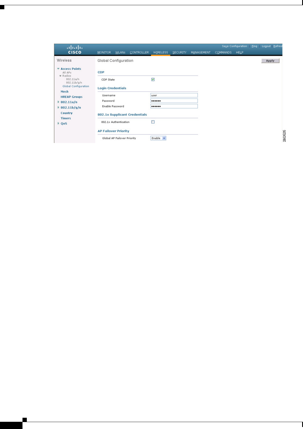
8-34
Cisco Wireless LAN Controller Configuration Guide
OL-21524-02
Chapter 8 Controlling Lightweight Access Points
Configuring Global Credentials for Access Points
Figure 8-9 Global Configuration Page
Step 2 In the Username text box, enter the username that is to be inherited by all access points that join the
controller.
Step 3 In the Password text box, enter the password that is to be inherited by all access points that join the
controller.
You can set a global username, password, and enable password that all access points inherit as they join
the controller including access points that are currently joined to the controller and any that join in the
future. You can override the global credentials and assign a unique username, password, and enable
password for a specific access point. The following are requirements enforced on the password:
• The password should contain characters from at least three of the following classes: lower case
letters, upper case letters, digits, and special characters.
• No character in the password can be repeated more than three times consecutively.
• The password should not contain the management username or the reverse of the username.
• The password should not contain words like Cisco, oscic, admin, nimda or any variant obtained by
changing the capitalization of letters by substituting 1, |, or ! or substituting 0 for o or substituting
$ for s.
Step 4 In the Enable Password text box, enter the enable password that is to be inherited by all access points
that join the controller.
Step 5 Click Apply to send the global username, password, and enable password to all access points that are
currently joined to the controller or that join the controller in the future.
Step 6 Click Save Configuration to save your changes.
Step 7 (Optional) Override the global credentials for a specific access point and assign a unique username,
password, and enable password to this access point as follows:
a. Choose Access Points > All APs to open the All APs page.
b. Click the name of the access point for which you want to override the global credentials.
c. Choose the Credentials tab. The All APs > Details for (Credentials) page appears (see Figure 8-10).

8-35
Cisco Wireless LAN Controller Configuration Guide
OL-21524-02
Chapter 8 Controlling Lightweight Access Points
Configuring Global Credentials for Access Points
Figure 8-10 All APs > Details for (Credentials) Page
d. Select the Over-ride Global Credentials check box to prevent this access point from inheriting the
global username, password, and enable password from the controller. The default value is
unselected.
e. In the Username, Password, and Enable Password text boxes, enter the unique username, password,
and enable password that you want to assign to this access point.
Note The information that you enter is retained across controller and access point reboots and if
the access point joins a new controller.
f. Click Apply to commit your changes.
g. Click Save Configuration to save your changes.
Note If you want to force this access point to use the controller’s global credentials, unselect the
Over-ride Global Credentials check box.
Using the CLI to Configure Global Credentials for Access Points
To configure global credentials for access points that join the controller using the controller CLI, follow
these steps:
Step 1 Configure the global username, password, and enable password for all access points currently joined to
the controller as well as any access points that join the controller in the future by entering this command:
config ap mgmtuser add username user password password enablesecret enable_password all
Step 2 (Optional) Override the global credentials for a specific access point and assign a unique username,
password, and enable password to this access point by entering this command:
config ap mgmtuser add username user password password enablesecret enable_password Cisco_AP
The credentials that you enter in this command are retained across controller and access point reboots
and if the access point joins a new controller.

8-36
Cisco Wireless LAN Controller Configuration Guide
OL-21524-02
Chapter 8 Controlling Lightweight Access Points
Configuring Global Credentials for Access Points
Note If you want to force this access point to use the controller’s global credentials, enter the config
ap mgmtuser delete Cisco_AP command. The following message appears after you execute this
command: “AP reverted to global username configuration.”
Step 3 Save your changes by entering this command:
save config
Step 4 Verify that global credentials are configured for all access points that join the controller by entering this
command:
show ap summary
Information similar to the following appears:
Number of APs.................................... 1
Global AP User Name.............................. globalap
AP Name Slots AP Model Ethernet MAC Location Port Country
-------- ------ ------------------- ------------------ ------------------ ---- -------
HReap 2 AIR-AP1131AG-N-K9 00:13:80:60:48:3e default location 1 US
Note If global credentials are not configured, the Global AP User Name text box shows “Not
Configured.”
To view summary of specific access point you can specify the access point name. You can also use
wildcard searches when filtering for access points.
Step 5 See the global credentials configuration for a specific access point by entering this command:
show ap config general Cisco_AP
Note The name of the access point is case sensitive.
Information similar to the following appears:
Cisco AP Identifier.............................. 0
Cisco AP Name.................................. HReap
...
AP User Mode..................................... AUTOMATIC
AP User Name..................................... globalap
Note If this access point is configured for global credentials, the AP User Mode text boxes shows
“Automatic.” If the global credentials have been overwritten for this access point, the AP User
Mode text box shows “Customized.”

8-37
Cisco Wireless LAN Controller Configuration Guide
OL-21524-02
Chapter 8 Controlling Lightweight Access Points
Configuring Authentication for Access Points
Configuring Authentication for Access Points
You can configure 802.1X authentication between a lightweight access point and a Cisco switch. The
access point acts as an 802.1X supplicant and is authenticated by the switch using EAP-FAST with
anonymous PAC provisioning.
This feature is supported on the following hardware:
• Cisco Aironet 1130, 1140, 1240, 1250, 1260, and 3500 series access points
• All controller platforms running in local, hybrid-REAP, monitor, or sniffer mode. Bridge mode is
not supported.
Note In hybrid-REAP mode, you can configure local switching with 802.1X authentication if you
have configured a local external RADIUS server configured.
• All Cisco switches that support authentication.
Note See the Release Notes for Cisco wireless LAN controllers and Lightweight Access Points for
Release 7.0.155.0 for a list of supported switch hardware and minimum supported software.
Note The OEAP 600 Series access points do not support LEAP.
You can configure global authentication settings that all access points that are currently joined to the
controller and any that join in the future. If desired, you can override the global authentication settings
and assign unique authentication settings for a specific access point.
Observe the following process for configuring authentication for access points:
Step 1 If the access point is new, do the following:
a. Boot the access point with the installed recovery image.
b. If you choose not to follow this suggested flow and instead enable 802.1X authentication on the
switch port connected to the access point prior to the access point joining the controller, enter
this command:
lwapp ap dot1x username username password password
Note If you choose to follow this suggested flow and enable 802.1X authentication on the
switch port after the access point has joined the controller and received the configured
802.1X credentials, you do not need to enter this command.
Note This command is available only for access points that are running the 5.1, 5.2, 6.0, or
7.0 recovery image.
c. Connect the access point to the switch port.
Step 2 Install the 5.1, 5.2, 6.0, or 7.0 image on the controller and reboot the controller.
Step 3 Allow all access points to join the controller.

8-38
Cisco Wireless LAN Controller Configuration Guide
OL-21524-02
Chapter 8 Controlling Lightweight Access Points
Configuring Authentication for Access Points
Step 4 Configure authentication on the controller. See the “Using the GUI to Configure Authentication for
Access Points” section on page 8-38 or the “Using the CLI to Configure Authentication for Access
Points” section on page 8-39 for information on configuring authentication on the controller.
Step 5 Configure the switch to allow authentication. See the “Configuring the Switch for Authentication”
section on page 8-41 for information on configuring the switch for authentication.
Using the GUI to Configure Authentication for Access Points
To configure authentication for access points that join the controller using the controller GUI, follow
these steps:
Step 1 Choose Wireless > Access Points > Global Configuration to open the Global Configuration page.
Step 2 Under 802.1x Supplicant Credentials, select the 802.1x Authentication check box.
Step 3 In the Username text box, enter the username that is to be inherited by all access points that join the
controller.
Step 4 In the Password and Confirm Password text boxes, enter the password that is to be inherited by all access
points that join the controller.
Note You must enter a strong password in these text boxes. Strong passwords have the following
characteristics:
- They are at least eight characters long.
- They contain a combination of uppercase and lowercase letters, numbers, and symbols.
- They are not a word in any language.
Step 5 Click Apply to send the global authentication username and password to all access points that are
currently joined to the controller and to any that join the controller in the future.
Step 6 Click Save Configuration to save your changes.
Step 7 If desired, you can choose to override the global authentication settings and assign a unique username
and password to a specific access point as follows:
a. Choose Access Points > All APs to open the All APs page.
b. Click the name of the access point for which you want to override the authentication settings.
c. Choose the Credentials tab to open the All APs > Details for (Credentials) page (see Figure 8-11).
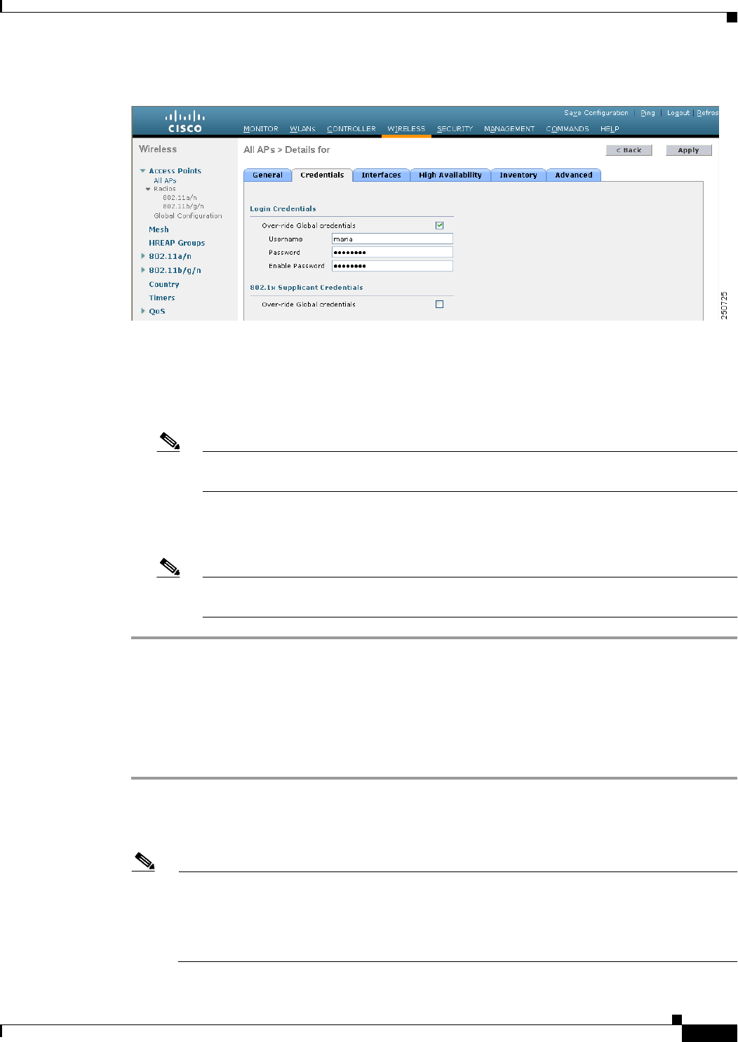
8-39
Cisco Wireless LAN Controller Configuration Guide
OL-21524-02
Chapter 8 Controlling Lightweight Access Points
Configuring Authentication for Access Points
Figure 8-11 All APs > Details for (Credentials) Page
d. Under 802.1x Supplicant Credentials, select the Over-ride Global Credentials check box to
prevent this access point from inheriting the global authentication username and password from the
controller. The default value is unselected.
e. In the Username, Password, and Confirm Password text boxes, enter the unique username and
password that you want to assign to this access point.
Note The information that you enter is retained across controller and access point reboots and
whenever the access point joins a new controller.
f. Click Apply to commit your changes.
g. Click Save Configuration to save your changes.
Note If you want to force this access point to use the controller’s global authentication settings,
unselect the Over-ride Global Credentials check box.
Using the CLI to Configure Authentication for Access Points
To configure authentication for access points that join the controller using the controller CLI, follow
these steps:
Step 1 Configure the global authentication username and password for all access points currently joined to the
controller as well as any access points that join the controller in the future by entering this command:
config ap dot1xuser add username user password password all
Note You must enter a strong password for the password parameter. Strong passwords have the
following characteristics:
- They are at least eight characters long.
- They contain a combination of uppercase and lowercase letters, numbers, and symbols.
- They are not a word in any language.

8-40
Cisco Wireless LAN Controller Configuration Guide
OL-21524-02
Chapter 8 Controlling Lightweight Access Points
Configuring Authentication for Access Points
Step 2 (Optional) Override the global authentication settings and assign a unique username and password to a
specific access point. To do so, enter this command:
config ap dot1xuser add username user password password Cisco_AP
Note You must enter a strong password for the password parameter. See the note in Step 1 for the
characteristics of strong passwords.
The authentication settings that you enter in this command are retained across controller and access point
reboots and whenever the access point joins a new controller.
Note If you want to force this access point to use the controller’s global authentication settings, enter
the config ap dot1xuser delete Cisco_AP command. The following message appears after you
execute this command: “AP reverted to global username configuration.”
Step 3 Save your changes by entering this command:
save config
Step 4 (Optional) Disable 802.1X authentication for all access points or for a specific access point by entering
this command:
config ap dot1xuser disable {all | Cisco_AP}
Note You can disable 802.1X authentication for a specific access point only if global 802.1X
authentication is not enabled. If global 802.1X authentication is enabled, you can disable 802.1X
for all access points only.
Step 5 See the authentication settings for all access points that join the controller by entering this command:
show ap summary
Information similar to the following appears:
Number of APs.................................... 1
Global AP User Name.............................. globalap
Global AP Dot1x User Name........................ globalDot1x
Note If global authentication settings are not configured, the Global AP Dot1x User Name text box
shows “Not Configured.”
To See summary of specific access point you can specify the access point name. You can also use
wildcard searches when filtering for access points.
Step 6 See the authentication settings for a specific access point by entering this command:
show ap config general Cisco_AP
Note The name of the access point is case sensitive.
Information similar to the following appears:
Cisco AP Identifier.............................. 0
Cisco AP Name.................................. HReap
...

8-41
Cisco Wireless LAN Controller Configuration Guide
OL-21524-02
Chapter 8 Controlling Lightweight Access Points
Embedded Access Points
AP Dot1x User Mode............................... AUTOMATIC
AP Dot1x User Name............................... globalDot1x
...
Note If this access point is configured for global authentication, the AP Dot1x User Mode text boxes
shows “Automatic.” If the global authentication settings have been overwritten for this access
point, the AP Dot1x User Mode text box shows “Customized.”
Configuring the Switch for Authentication
To enable 802.1X authentication on a switch port, on the switch CLI, enter these commands:
• Switch# configure terminal
• Switch(config)# dot1x system-auth-control
• Switch(config)# aaa new-model
• Switch(config)# aaa authentication dot1x default group radius
• Switch(config)# radius-server host ip_addr auth-port port acct-port port key key
• Switch(config)# interface fastethernet2/1
• Switch(config-if)# switchport mode access
• Switch(config-if)# dot1x pae authenticator
• Switch(config-if)# dot1x port-control auto
• Switch(config-if)# end
Embedded Access Points
Controller software release 7.0.116.0 or later releases support the embedded access points: AP801 and
AP802, which are the integrated access points on the Cisco 880 Series Integrated Services Routers
(ISRs). This access points use a Cisco IOS software image that is separate from the router Cisco IOS
software image. The access points can operate as autonomous access points configured and managed
locally, or they can operate as centrally managed access points that utilize the CAPWAP or LWAPP
protocol. The AP801 and AP802 access points are preloaded with both an autonomous Cisco IOS release
and a recovery image for the unified mode.
Note Before you use an AP801 or AP802 Series Lightweight Access Point with controller software release
7.0.116.0 or later releases, you must upgrade the software in the Next Generation Cisco 880 Series
Integrated Services Routers (ISRs) to Cisco IOS 151-4.M or later.
When you want to use the AP801 or AP802 with a controller, you must enable the recovery image for
the unified mode on the access point by entering the service-module wlan-ap 0 bootimage unified
command on the router in privileged EXEC mode.

8-42
Cisco Wireless LAN Controller Configuration Guide
OL-21524-02
Chapter 8 Controlling Lightweight Access Points
Embedded Access Points
Note If the service-module wlan-ap 0 bootimage unified command does not work successfully, make sure
that the software license is still eligible.
After enabling the recovery image, enter the service-module wlan-ap 0 reload command on the router
to shut down and reboot the access point. After the access point reboots, it discovers the controller,
downloads the full CAPWAP or LWAPP software release from the controller, and acts as a lightweight
access point.
Note To use the CLI commands mentioned above, the router must be running Cisco IOS Release 12.4(20)T or
later releases. If you experience any problems, See the “Troubleshooting an Upgrade or Reverting the
AP to Autonomous Mode” section in the ISR configuration guide at this URL:
http://www.cisco.com/en/US/docs/routers/access/800/860-880-890/software/configuration/guide/admi
n_ap.html#wp1061143
In order to support CAPWAP or LWAPP, the router must be activated with at least the Cisco Advanced
IP Services IOS license-grade image. A license is required to upgrade to this Cisco IOS image on the
router. See this URL for licensing information:
http://www.cisco.com/en/US/docs/routers/access/sw_activation/SA_on_ISR.html
After the AP801 or AP802 boots up with the recovery image for the unified mode, it requires an IP
address to communicate with the controller and to download its unified image and configuration from
the controller. The router can provide DHCP server functionality, the DHCP pool to reach the controller,
and setup option 43 for the controller IP address in the DHCP pool configuration. Use the following
configuration to perform this task:

8-43
Cisco Wireless LAN Controller Configuration Guide
OL-21524-02
Chapter 8 Controlling Lightweight Access Points
Autonomous Access Points Converted to Lightweight Mode
ip dhcp pool pool_name
network ip_address subnet_mask
dns-server ip_address
default-router ip_address
option 43 hex controller_ip_address_in_hex
Example:
ip dhcp pool embedded-ap-pool
network 60.0.0.0 255.255.255.0
dns-server 171.70.168.183
default-router 60.0.0.1
option 43 hex f104.0a0a.0a0f /* single WLC IP address(10.10.10.15) in hex format */
The AP801 and AP802 802.11n radio supports lower power levels than the 802.11n radio in the Cisco
Aironet 1250 series access points. The AP801 and AP802 access points store the radio power levels and
passes them to the controller when the access point joins the controller. The controller uses the supplied
values to limit the user’s configuration.
The AP801 and AP802 access points can be used in hybrid-REAP mode. See Chapter 15, “Configuring
Hybrid REAP,” for more information on hybrid REAP.
Note For more information on the AP801, see the documentation for the Cisco 800 Series ISRs at this URL:
http://www.cisco.com/en/US/products/hw/routers/ps380/tsd_products_support_series_home.html.
Note For more information on the AP802, see the documentation for the Next generation Cisco 880 Series
ISRs at
http://www.cisco.com/en/US/docs/routers/access/800/860-880-890/software/configuration/guide/860-8
80-890SCG.html.
Autonomous Access Points Converted to Lightweight Mode
You can use an upgrade conversion tool to convert autonomous Cisco Aironet 1100, 1130AG, 1200,
1240AG, and 1300 Series Access Points to lightweight mode. When you upgrade one of these access
points to lightweight mode, the access point communicates with a controller and receives a configuration
and software image from the controller.
See the Upgrading Autonomous Cisco Aironet Access Points to Lightweight Mode document for
instructions on upgrading an autonomous access point to lightweight mode. You can find this document
at this URL:
http://www.cisco.com/en/US/docs/wireless/access_point/conversion/lwapp/upgrade/guide/lwapnote.ht
ml

8-44
Cisco Wireless LAN Controller Configuration Guide
OL-21524-02
Chapter 8 Controlling Lightweight Access Points
Autonomous Access Points Converted to Lightweight Mode
Guidelines for Using Access Points Converted to Lightweight Mode
Follow these guidelines when you use autonomous access points that have been converted to lightweight
mode:
• Access points converted to lightweight mode do not support Wireless Domain Services (WDS).
Converted access points communicate only with Cisco wireless LAN controllers and cannot
communicate with WDS devices. However, the controller provides functionality that is equivalent
to WDS when the access point associates to it.
• In controller software release 4.2 or later releases, all Cisco lightweight access points support 16
BSSIDs per radio and a total of 16 wireless LANs per access point. In previous releases, they
supported only 8 BSSIDs per radio and a total of 8 wireless LANs per access point. When a
converted access point associates to a controller, only wireless LANs with IDs 1 through 16 are
pushed to the access point.
• Access points converted to lightweight mode must get an IP address and discover the controller
using DHCP, DNS, or IP subnet broadcast.
• After you convert an access point to lightweight mode, the console port provides read-only access
to the unit.
• The 1130AG and 1240AG access points support hybrid-REAP mode. See Chapter 15, “Configuring
Hybrid REAP,” for details.
• The upgrade conversion tool adds the self-signed certificate (SSC) key-hash to only one of the
controllers on the Cisco WiSM. After the conversion has been completed, add the SSC key-hash to
the second controller on the Cisco WiSM by copying the SSC key-hash from the first controller to
the second controller. To copy the SSC key-hash, open the AP Policies page of the controller GUI
(Security > AAA > AP Policies) and copy the SSC key-hash from the SHA1 Key Hash column
under AP Authorization List (see Figure 8-14). Then, using the second controller’s GUI, open the
same page and paste the key-hash into the SHA1 Key Hash text box under Add AP to Authorization
List. If you have more than one Cisco WiSM, use WCS to push the SSC key-hash to all the other
controllers.
Reverting from Lightweight Mode to Autonomous Mode
After you use the upgrade tool to convert an autonomous access point to lightweight mode, you can
convert the access point from a lightweight unit back to an autonomous unit by loading a Cisco IOS
release that supports autonomous mode (Cisco IOS Release 12.3(7)JA or earlier releases). If the access
point is associated to a controller, you can use the controller to load the Cisco IOS release. If the access
point is not associated to a controller, you can load the Cisco IOS release using TFTP. In either method,
the access point must be able to access a TFTP server that contains the Cisco IOS release to be loaded.
Using a Controller to Return to a Previous Release
To revert from lightweight mode to autonomous mode using a wireless LAN controller, follow these
steps:
Step 1 Log into the CLI on the controller to which the access point is associated.
Step 2 Revert from lightweight mode, by entering this command:
config ap tftp-downgrade tftp-server-ip-address filename access-point-name

8-45
Cisco Wireless LAN Controller Configuration Guide
OL-21524-02
Chapter 8 Controlling Lightweight Access Points
Autonomous Access Points Converted to Lightweight Mode
Step 3 Wait until the access point reboots and reconfigure the access point using the CLI or GUI.
Using the MODE Button and a TFTP Server to Return to a Previous Release
To revert from lightweight mode to autonomous mode by using the access point MODE (reset) button to
load a Cisco IOS release from a TFTP server, follow these steps:
Step 1 Configure the PC on which your TFTP server software runs with a static IP address in the range of
10.0.0.2 to 10.0.0.30.
Step 2 Make sure that the PC contains the access point image file (such as c1200-k9w7-tar.123-7.JA.tar for a
1200 series access point) in the TFTP server folder and that the TFTP server is activated.
Step 3 Rename the access point image file in the TFTP server folder to c1200-k9w7-tar.default for a 1200
series access point.
Step 4 Connect the PC to the access point using a Category 5 (CAT5) Ethernet cable.
Step 5 Disconnect power from the access point.
Step 6 Press and hold the MODE button while you reconnect power to the access point.
Note The MODE button on the access point must be enabled. Follow the steps in the “Disabling the
Reset Button on Access Points Converted to Lightweight Mode” section on page 8-66 to select
the status of the access point MODE button.
Step 7 Hold the MODE button until the status LED turns red (approximately 20 to 30 seconds), and release the
MODE button.
Step 8 Wait until the access point reboots as indicated by all LEDs turning green followed by the Status LED
blinking green.
Step 9 After the access point reboots, reconfigure the access point using the GUI or the CLI.
Authorizing Access Points
In controller software releases prior to 5.2, the controller may either use self-signed certificates (SSCs)
to authenticate access points or send the authorization information to a RADIUS server (if access points
have manufactured-installed certificates [MICs]). In controller software release 5.2 or later releases, you
can configure the controller to use a local significant certificate (LSC).
Authorizing Access Points Using SSCs
The Control and Provisioning of Wireless Access Points protocol (CAPWAP) secures the control
communication between the access point and controller by a secure key distribution requiring X.509
certificates on both the access point and controller. CAPWAP relies on provisioning of the X.509
certificates. Cisco Aironet access points shipped before July 18, 2005 do not have a MIC, so these access
points create an SSC when upgraded to operate in lightweight mode. Controllers are programmed to
accept local SSCs for authentication of specific access points and do not forward those authentication
requests to a RADIUS server. This behavior is acceptable and secure.

8-46
Cisco Wireless LAN Controller Configuration Guide
OL-21524-02
Chapter 8 Controlling Lightweight Access Points
Autonomous Access Points Converted to Lightweight Mode
Authorizing Access Points Using MICs
You can configure controllers to use RADIUS servers to authorize access points using MICs. The
controller uses an access point’s MAC address as both the username and password when sending the
information to a RADIUS server. For example, if the MAC address of the access point is 000b85229a70,
both the username and password used by the controller to authorize the access point are 000b85229a70.
Note The lack of a strong password by the use of the access point’s MAC address should not be an issue
because the controller uses MIC to authenticate the access point prior to authorizing the access point
through the RADIUS server. Using MIC provides strong authentication.
Note If you use the MAC address as the username and password for access point authentication on a RADIUS
AAA server, do not use the same AAA server for client authentication.
Authorizing Access Points Using LSCs
You can use an LSC if you want your own public key infrastructure (PKI) to provide better security, to
have control of your certificate authority (CA), and to define policies, restrictions, and usages on the
generated certificates.
The LSC CA certificate is installed on access points and controllers. You need to provision the device
certificate on the access point. The access point gets a signed X.509 certificate by sending a certRequest
to the controller. The controller acts as a CA proxy and receives the certRequest signed by the CA for
the access point.
Note Access points that are configured for bridge mode are not supported.
Using the GUI to Configure LSC
To enable the use of LSC on the controller using the controller GUI, follow these steps:
Step 1 Choose Security > Certificate > LSC to open the Local Significant Certificates (LSC) - General page
(see Figure 8-12).
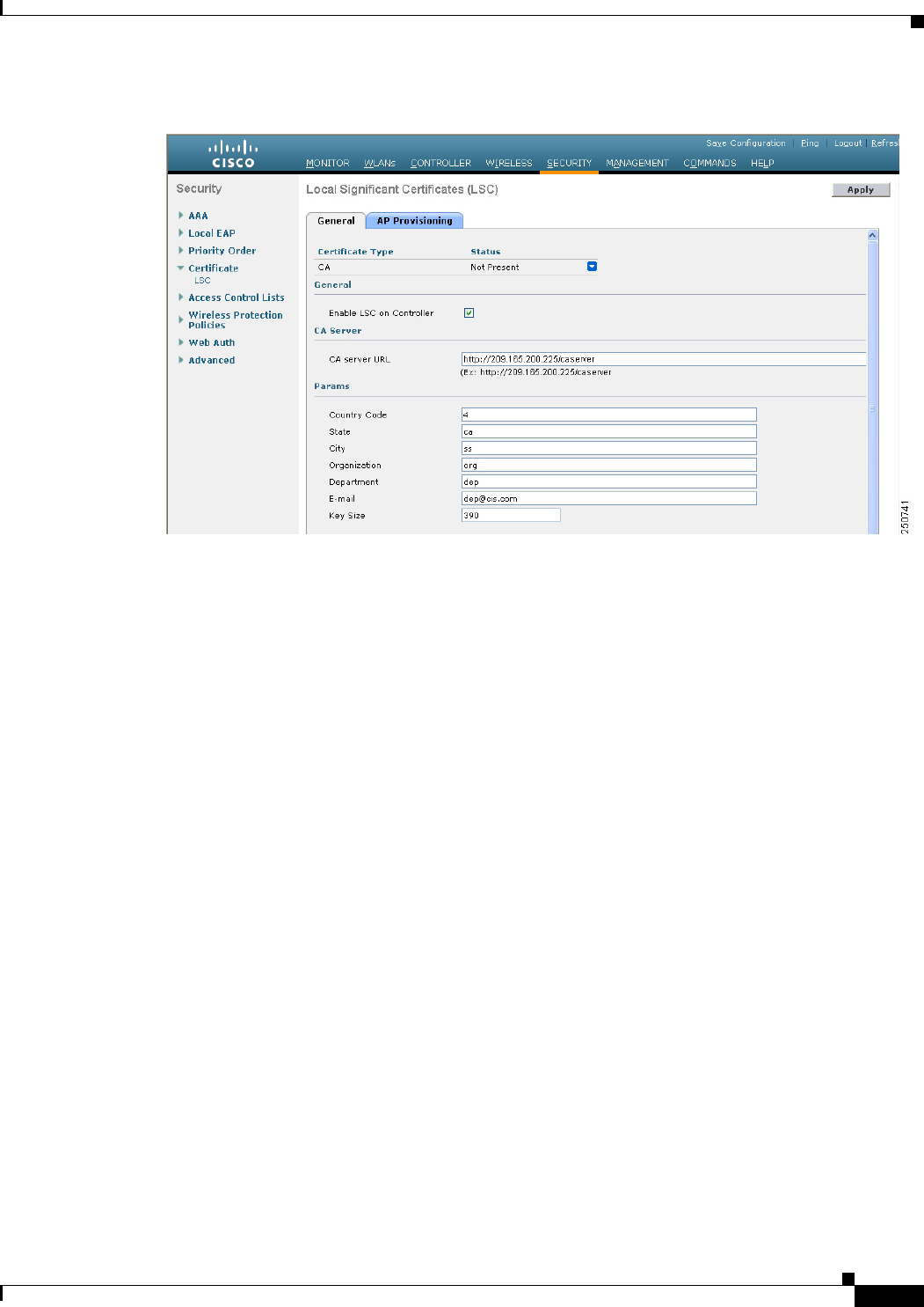
8-47
Cisco Wireless LAN Controller Configuration Guide
OL-21524-02
Chapter 8 Controlling Lightweight Access Points
Autonomous Access Points Converted to Lightweight Mode
Figure 8-12 Local Significant Certificates (LSC) - General Page
Step 2 Select the Enable LSC on Controller check box to enable the LSC on the system.
Step 3 In the CA Server URL text box, enter the URL to the CA server. You can enter either a domain name or
an IP address.
Step 4 In the Params text boxes, enter the parameters for the device certificate. The key size is a value from 384
to 2048 (in bits), and the default value is 2048.
Step 5 Click Apply to commit your changes.
Step 6 To add the CA certificate into the controller’s CA certificate database, hover your cursor over the blue
drop-down arrow for the certificate type and choose Add.
Step 7 Choose the AP Provisioning tab to open the Local Significant Certificates (LSC) - AP Provisioning page
(see Figure 8-13).
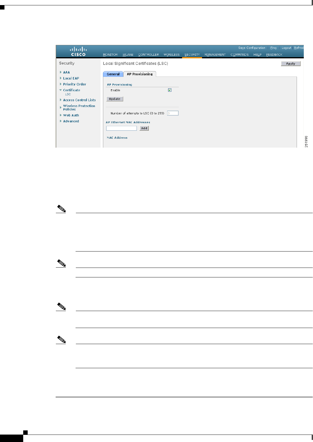
8-48
Cisco Wireless LAN Controller Configuration Guide
OL-21524-02
Chapter 8 Controlling Lightweight Access Points
Autonomous Access Points Converted to Lightweight Mode
Figure 8-13 Local Significant Certificates (LSC) - AP Provisioning Page
Step 8 Select the Enable check box and click Update to provision the LSC on the access point.
Step 9 When a message appears indicating that the access points will be rebooted, click OK.
Step 10 In the Number of Attempts to LSC text box, enter the number of times that the access point attempts to
join the controller using an LSC before the access point reverts to the default certificate (MIC or SSC).
The range is 0 to 255 (inclusive), and the default value is 3.
Note If you set the number of retries to a nonzero value and the access point fails to join the controller
using an LSC after the configured number of retries, the access point reverts to the default
certificate. If you set the number of retries to 0 and the access point fails to join the controller
using an LSC, the access point does not attempt to join the controller using the default
certificate.
Note If you are configuring LSC for the first time, we recommend that you configure a nonzero value.
Step 11 Enter the access point MAC address in the AP Ethernet MAC Addresses text box and click Add to add
access points to the provision list.
Note To remove an access point from the provision list, hover your cursor over the blue drop-down
arrow for the access point and choose Remove.
Note If you configure an access point provision list, only the access points in the provision list are
provisioned when you enable AP provisioning. If you do not configure an access point provision
list, all access points with a MIC or SSC certificate that join the controller are LSC provisioned.
Step 12 Click Apply to commit your changes.
Step 13 Click Save Configuration to save your changes.

8-49
Cisco Wireless LAN Controller Configuration Guide
OL-21524-02
Chapter 8 Controlling Lightweight Access Points
Autonomous Access Points Converted to Lightweight Mode
Using the CLI to Configure LSC
To enable the use of LSC on the controller using the controller CLI, follow these steps:
Step 1 Enable LSC on the system by entering this command:
config certificate lsc {enable | disable}
Step 2 Configure the URL to the CA server by entering this command:
config certificate lsc ca-server http://url:port/path
where url can be either a domain name or IP address.
Note You can configure only one CA server. To configure a different CA server, delete the configured
CA server using the config certificate lsc ca-server delete command, and then configure a
different CA server.
Step 3 Add the LSC CA certificate into the controller’s CA certificate database by entering this command:
config certificate lsc ca-cert {add | delete}
Step 4 Configure the parameters for the device certificate by entering this command:
config certificate lsc subject-params country state city orgn dept e-mail
Note The common name (CN) is generated automatically on the access point using the current
MIC/SSC format Cxxxx-MacAddr, where xxxx is the product number.
Step 5 Configure a key size by entering this command:
config certificate lsc other-params keysize
The keysize is a value from 384 to 2048 (in bits), and the default value is 2048.
Step 6 Add access points to the provision list by entering this command:
config certificate lsc ap-provision auth-list add AP_mac_addr
Note To remove access points from the provision list, enter the config certificate lsc ap-provision
auth-list delete AP_mac_addr command.
Note If you configure an access point provision list, only the access points in the provision list are
provisioned when you enable AP provisioning (in Step 8). If you do not configure an access
point provision list, all access points with a MIC or SSC certificate that join the controller are
LSC provisioned.
Step 7 Configure the number of times that the access point attempts to join the controller using an LSC before
the access point reverts to the default certificate (MIC or SSC) by entering this command:
config certificate lsc ap-provision revert-cert retries
where retries is a value from 0 to 255, and the default value is 3.

8-50
Cisco Wireless LAN Controller Configuration Guide
OL-21524-02
Chapter 8 Controlling Lightweight Access Points
Autonomous Access Points Converted to Lightweight Mode
Note If you set the number of retries to a nonzero value and the access point fails to join the controller
using an LSC after the configured number of retries, the access point reverts to the default
certificate. If you set the number of retries to 0 and the access point fails to join the controller
using an LSC, the access point does not attempt to join the controller using the default
certificate.
Note If you are configuring LSC for the first time, we recommend that you configure a nonzero value.
Step 8 Provision the LSC on the access point by entering this command:
config certificate lsc ap-provision {enable | disable}
Step 9 See the LSC summary by entering this command:
show certificate lsc summary
Information similar to the following appears:
LSC Enabled.......................................... Yes
LSC CA-Server........................................ http://10.0.0.1:8080/caserver
LSC AP-Provisioning.................................. Yes
Provision-List................................... Not Configured
LSC Revert Count in AP reboots................... 3
LSC Params:
Country.......................................... 4
State............................................ ca
City............................................. ss
Orgn............................................. org
Dept............................................. dep
Email............................................ dep@co.com
KeySize.......................................... 390
LSC Certs:
CA Cert.......................................... Not Configured
RA Cert....................................... Not Configured
Step 10 See details about the access points that are provisioned using LSC by entering this command:
show certificate lsc ap-provision
Information similar to the following appears:
LSC AP-Provisioning........................... Yes
Provision-List................................ Present
Idx Mac Address
--- ------------
1 00:18:74:c7:c0:90
Using the GUI to Authorize Access Points
To authorize access points using the controller GUI, follow these steps:
Step 1 Choose Security > AAA > AP Policies to open the AP Policies page (see Figure 8-14).
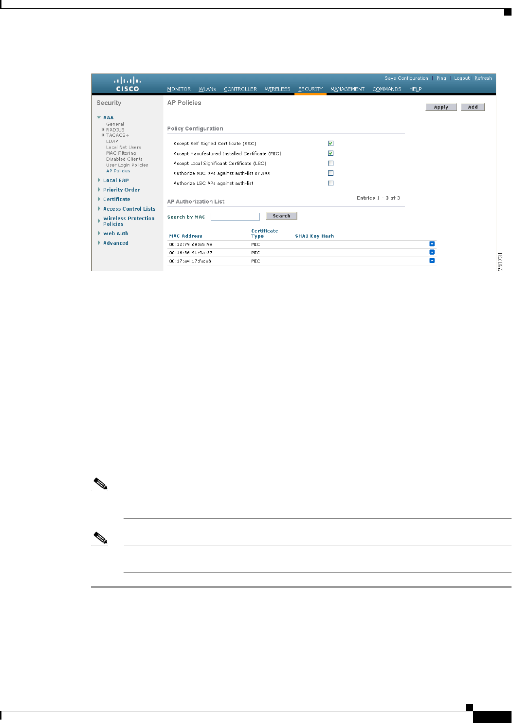
8-51
Cisco Wireless LAN Controller Configuration Guide
OL-21524-02
Chapter 8 Controlling Lightweight Access Points
Autonomous Access Points Converted to Lightweight Mode
Figure 8-14 AP Policies Page
Step 2 If you want the access point to accept self-signed certificates (SSCs), manufactured-installed certificates
(MICs), or local significant certificates (LSCs), select the appropriate check box.
Step 3 If you want the access points to be authorized using a AAA RADIUS server, select the Authorize MIC
APs against auth-list or AAA check box.
Step 4 If you want the access points to be authorized using an LSC, select the Authorize LSC APs against
auth-list check box.
Step 5 Click Apply to commit your changes.
Step 6 Follow these steps to add an access point to the controller’s authorization list:
a. Click Add to access the Add AP to Authorization List area.
b. In the MAC Address text box, enter the MAC address of the access point.
c. From the Certificate Type drop-down list, choose MIC, SSC, or LSC.
d. Click Add. The access point appears in the access point authorization list.
Note To remove an access point from the authorization list, hover your cursor over the blue drop-down
arrow for the access point and choose Remove.
Note To search for a specific access point in the authorization list, enter the MAC address of the access
point in the Search by MAC text box and click Search.
Using the CLI to Authorize Access Points
To authorize access points using the controller CLI, follow these steps:

8-52
Cisco Wireless LAN Controller Configuration Guide
OL-21524-02
Chapter 8 Controlling Lightweight Access Points
Autonomous Access Points Converted to Lightweight Mode
Step 1 Configure an access point authorization policy by entering this command:
config auth-list ap-policy {authorize-ap {enable | disable} | authorize-lsc-ap {enable | disable}}
Step 2 Configure an access point to accept manufactured-installed certificates (MICs), self-signed certificates
(SSCs), or local significant certificates (LSCs) by entering this command:
config auth-list ap-policy {mic | ssc | lsc {enable | disable}}
Step 3 Add an access point to the authorization list by entering this command:
config auth-list add {mic | ssc | lsc} ap_mac [ap_key]
where ap_key is an optional key hash value equal to 20 bytes or 40 digits.
Note To delete an access point from the authorization list, enter this command:
config auth-list delete ap_mac.
Step 4 See the access point authorization list by entering this command:
show auth-list
Information similar to the following appears:
Authorize MIC APs against AAA ....................... disabled
Authorize LSC APs against Auth-List ................. disabled
Allow APs with MIC - Manufactured Installed C ....... enabled
Allow APs with SSC - Self-Signed Certificate ........ enabled
Allow APs with LSC - Locally Significant Cert ....... enabled
Mac Addr Cert Type Key Hash
----------------------- ---------- ---------------------------------------------
00:12:79:de:65:99 SSC ca528236137130d37049a5ef3d1983b30ad7e543
00:16:36:91:9a:27 MIC 593f34e7cb151997a28cc7da2a6cac040b329636
Using DHCP Option 43 and DHCP Option 60
Cisco Aironet access points use the type-length-value (TLV) format for DHCP option 43. DHCP servers
must be programmed to return the option based on the access point’s DHCP Vendor Class Identifier
(VCI) string (DHCP option 60). Table 8-19 lists the VCI strings for Cisco access points capable of
operating in lightweight mode.
Ta b l e 8-19 VCI Strings For Lightweight Access Points
Access Point VCI String
Cisco Aironet 1130 Series Cisco AP c1130
Cisco Aironet 1140 Series Cisco AP c1140
Cisco Aironet 1200 Series Cisco AP c1200
Cisco Aironet 1240 Series Cisco AP c1240
Cisco Aironet 1250 Series Cisco AP c1250
Cisco Aironet 1260 Series Cisco AP c1260

8-53
Cisco Wireless LAN Controller Configuration Guide
OL-21524-02
Chapter 8 Controlling Lightweight Access Points
Autonomous Access Points Converted to Lightweight Mode
The format of the TLV block is as follows:
• Type: 0xf1 (decimal 241)
• Length: Number of controller IP addresses * 4
• Value: List of the IP addresses of controller management interfaces
See the product documentation for your DHCP server for instructions on configuring DHCP option 43.
The Upgrading Autonomous Cisco Aironet Access Points to Lightweight Mode document contains
example steps for configuring option 43 on a DHCP server.
If the access point is ordered with the Service Provider Option - AIR-OPT60-DHCP selected, the VCI
string for that access point will be different than those listed above. The VCI string will have the
“ServiceProvider”. For example, a 1260 with this option will return this VCI string: "Cisco AP
c1260-ServiceProvider".
Note The controller IP address that you obtain from the DHCP server should be a unicast IP address.
Do not configure the controller IP address as a multicast address when configuring DHCP
Option 43.
Troubleshooting the Access Point Join Process
Access points can fail to join a controller for many reasons such as a RADIUS authorization is pending,
self-signed certificates are not enabled on the controller, the access point and controller’s regulatory
domains do not match, and so on.
Note For join information specific to an OfficeExtend access point, see the “OfficeExtend Access Points”
section on page 8-69.
Controller software release 5.2 or later releases enable you to configure the access points to send all
CAPWAP-related errors to a syslog server. You do not need to enable any debug commands on the
controller because all of the CAPWAP error messages can be viewed from the syslog server itself.
The state of the access point is not maintained on the controller until it receives a CAPWAP join request
from the access point, so it can be difficult to determine why the CAPWAP discovery request from a
certain access point was rejected. In order to troubleshoot such joining issues without enabling
CAPWAP debug commands on the controller, the controller collects information for all access points
that send a discovery message to this controller and maintains information for any access points that have
successfully joined this controller.
The controller collects all join-related information for each access point that sends a CAPWAP discovery
request to the controller. Collection begins with the first discovery message received from the access
point and ends with the last configuration payload sent from the controller to the access point.
Cisco Aironet 3500 Series Cisco AP c3500
Cisco AP801 Embedded Access Point Cisco AP801
Cisco AP802 Embedded Access Point Cisco AP802
Table 8-19 VCI Strings For Lightweight Access Points (continued)
Access Point VCI String

8-54
Cisco Wireless LAN Controller Configuration Guide
OL-21524-02
Chapter 8 Controlling Lightweight Access Points
Autonomous Access Points Converted to Lightweight Mode
You can view join-related information for the following numbers of access points:
• Up to 250 access points for Cisco 5500 Series Controllers
• Up to 300 access points for 4400 series controllers, the Cisco WiSM, and the Catalyst 3750G
Integrated Wireless LAN Controller Switch
• Up to three times the maximum number of access points supported by the platform for the Cisco
2100 Series Controller and the Controller Network Module within the Cisco 28/37/38xx Series
Integrated Services Routers
When the controller is maintaining join-related information for the maximum number of access points,
it does not collect information for any more access points.
An access point sends all syslog messages to IP address 255.255.255.255 by default when any of the
following conditions are met:
• An access point that runs software release 4.2 or later releases has been newly deployed.
• An existing access point that runs a software release prior to 4.2 releases has been upgraded to 4.2
or a later release.
• An existing access point that runs software release 4.2 or later releases has been reset after clearing
the configuration.
If any of these conditions are met and the access point has not yet joined a controller, you can also
configure a DHCP server to return a syslog server IP address to the access point using option 7 on the
server. The access point then starts sending all syslog messages to this IP address.
You can also configure the syslog server IP address through the access point CLI, provided the access
point is currently not connected to the controller by entering the lwapp ap log-server
syslog_server_IP_address command.
When the access point joins a controller for the first time, the controller pushes the global syslog server
IP address (the default is 255.255.255.255) to the access point. After that, the access point sends all
syslog messages to this IP address, until it is overridden by one of the following scenarios:
• The access point is still connected to the same controller, and the global syslog server IP address
configuration on the controller has been changed using the config ap syslog host global
syslog_server_IP_address command. In this case, the controller pushes the new global syslog server
IP address to the access point.
• The access point is still connected to the same controller, and a specific syslog server IP address has
been configured for the access point on the controller using the config ap syslog host specific
Cisco_AP syslog_server_IP_address command. In this case, the controller pushes the new specific
syslog server IP address to the access point.
• The access point gets disconnected from the controller, and the syslog server IP address has been
configured from the access point CLI using the lwapp ap log-server syslog_server_IP_address
command. This command works only if the access point is not connected to any controller.
• The access point gets disconnected from the controller and joins another controller. In this case, the
new controller pushes its global syslog server IP address to the access point.
Whenever a new syslog server IP address overrides the existing syslog server IP address, the old address
is erased from persistent storage, and the new address is stored in its place. The access point also starts
sending all syslog messages to the new IP address, provided the access point can reach the syslog server
IP address.
You can configure the syslog server for access points using the controller GUI and view the access point
join information using the controller GUI or CLI.