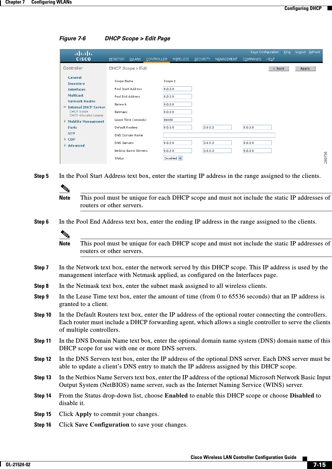
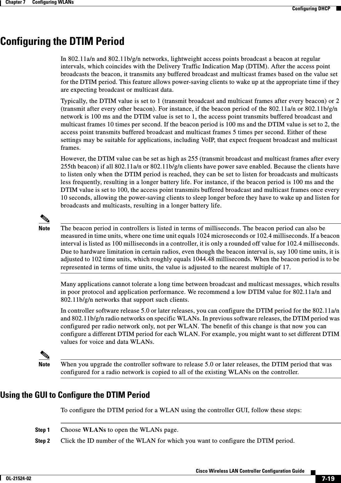
Cisco Systems 102075 Cisco Aironet 802.11n Dual Band Access Points User Manual Cisco Wireless LAN Controller Configuration Guide 4
Cisco Systems Inc Cisco Aironet 802.11n Dual Band Access Points Cisco Wireless LAN Controller Configuration Guide 4
Contents
- 1. User manual
- 2. Cisco Wireless LAN Controller Configuration Guide_1
- 3. Cisco Wireless LAN Controller Configuration Guide_2
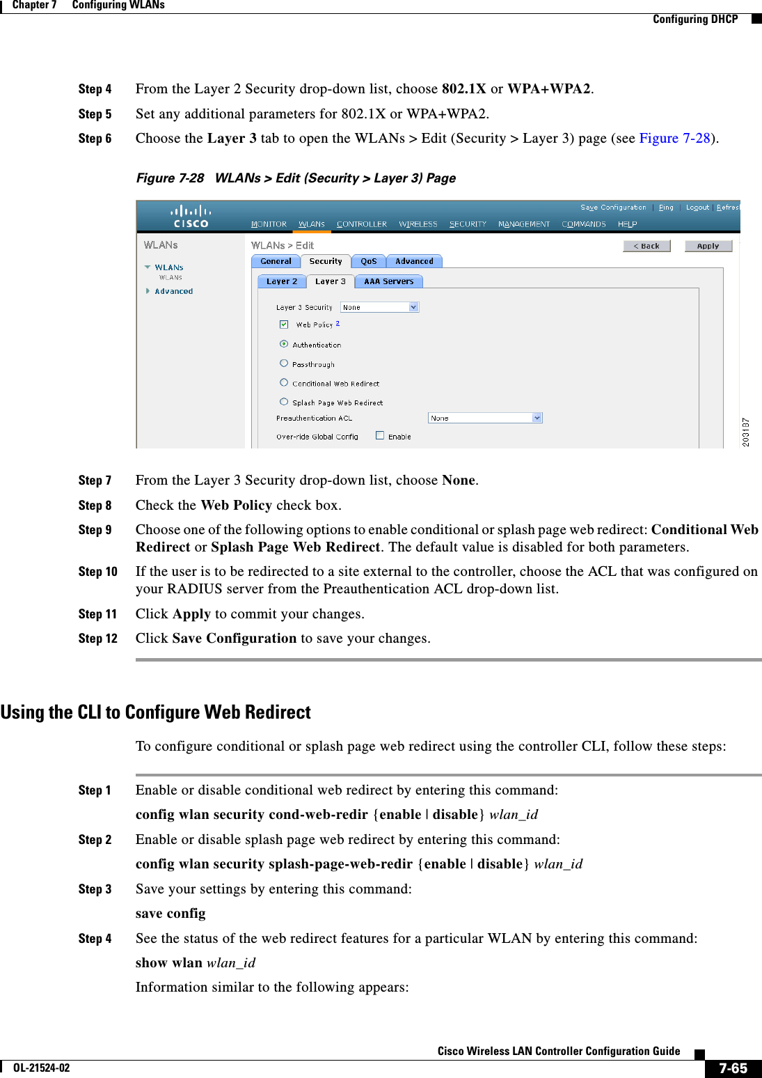
- 4. Cisco Wireless LAN Controller Configuration Guide_3
- 5. Cisco Wireless LAN Controller Configuration Guide_4
- 6. Cisco Wireless LAN Controller Configuration Guide_5
- 7. Cisco Wireless LAN Controller Configuration Guide_6
- 8. Cisco Wireless LAN Controller Configuration Guide_7
- 9. Cisco Wireless LAN Controller Configuration Guide_8
- 10. Cisco Wireless LAN Controller Configuration Guide_9
- 11. Cisco Wireless LAN Controller Configuration Guide_10
- 12. Cisco Wireless LAN Controller Configuration Guide_11
- 13. User Manual
Cisco Wireless LAN Controller Configuration Guide_4
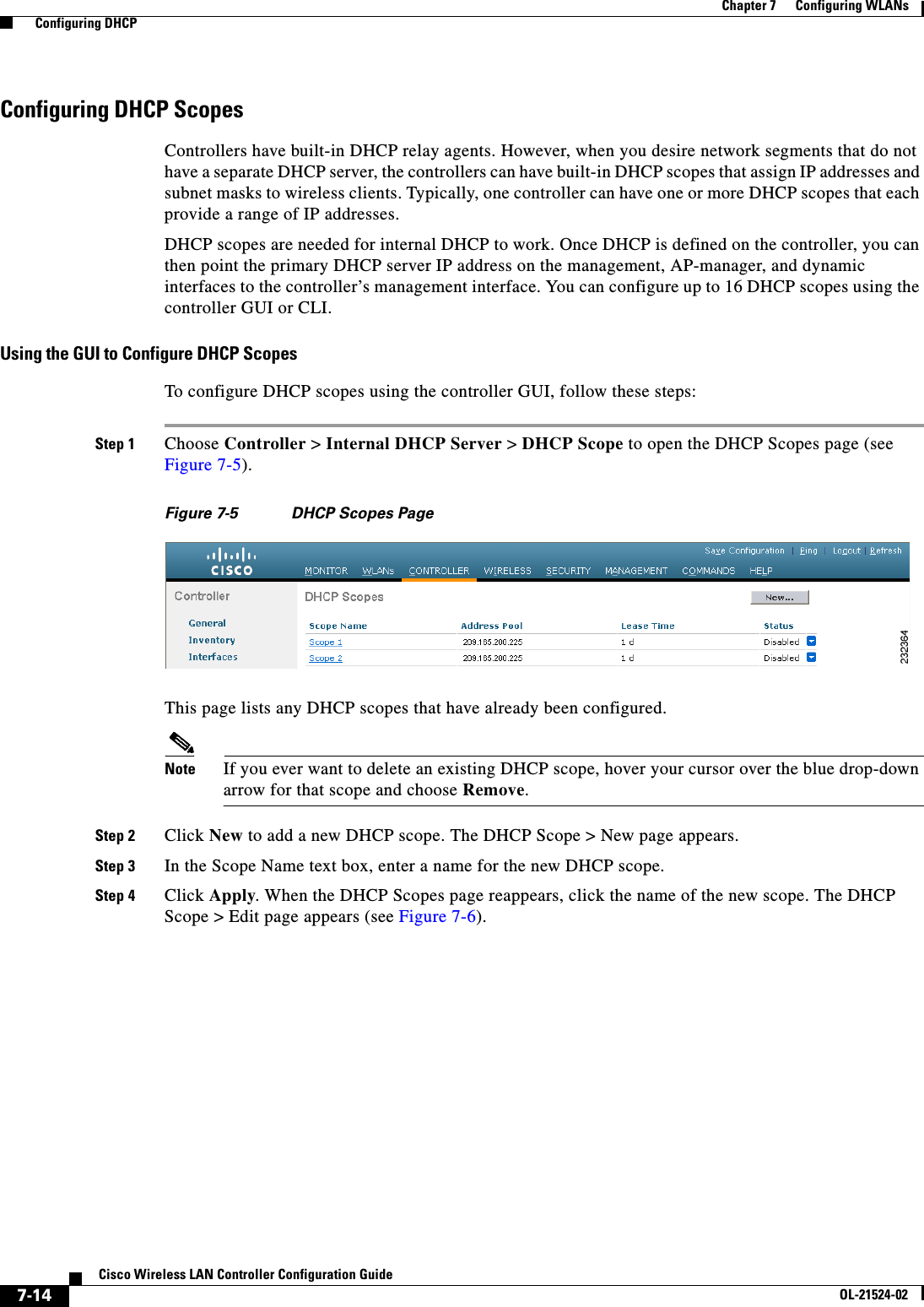
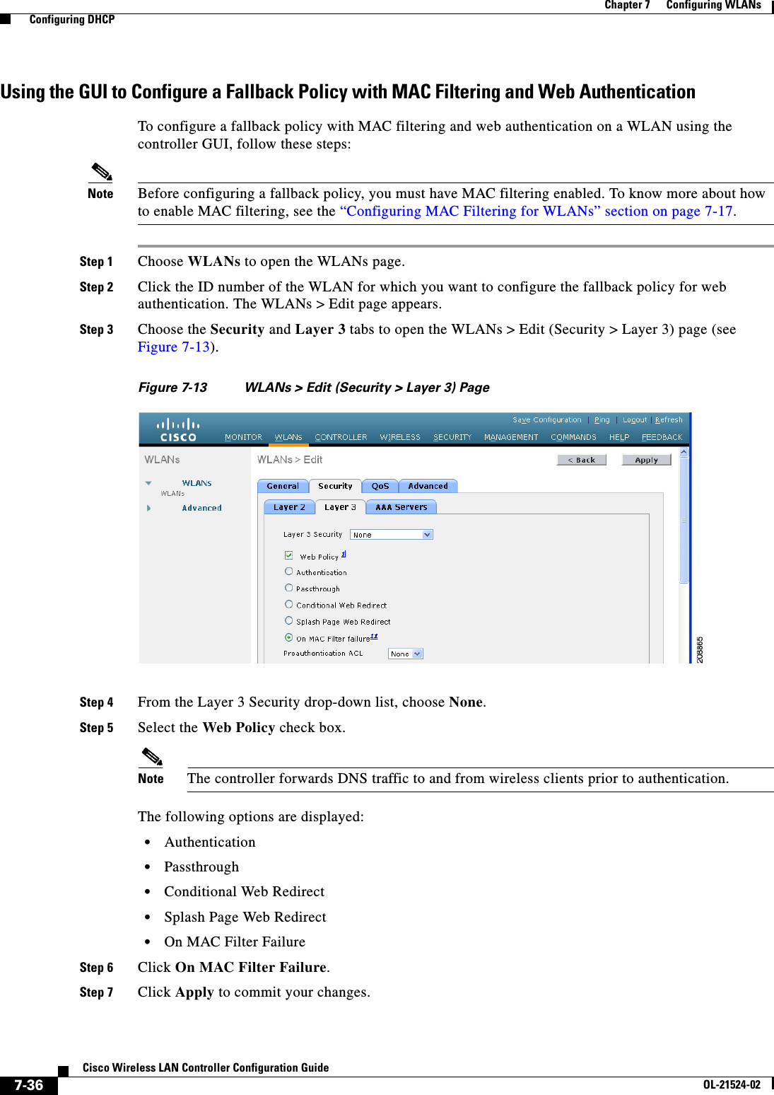
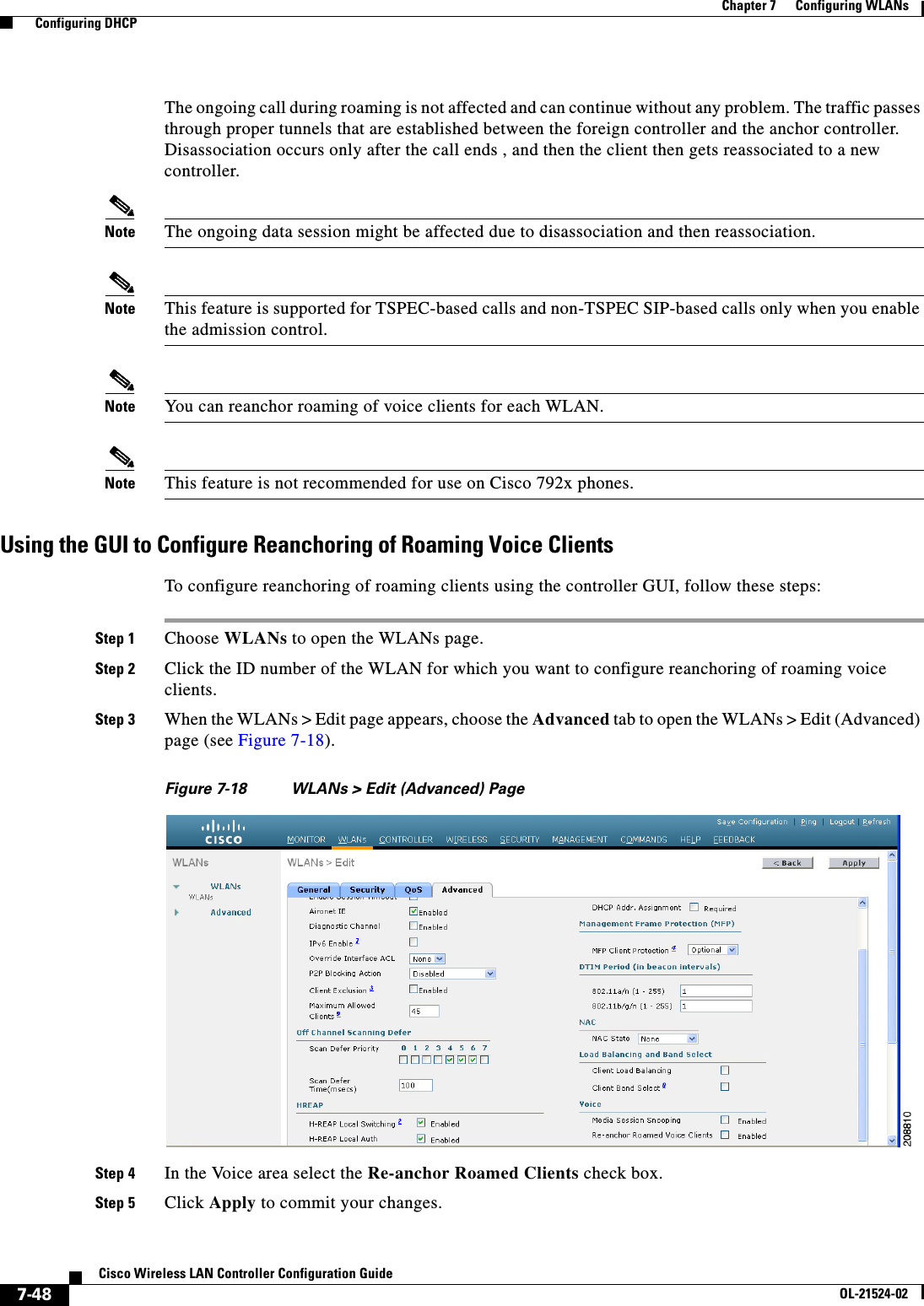
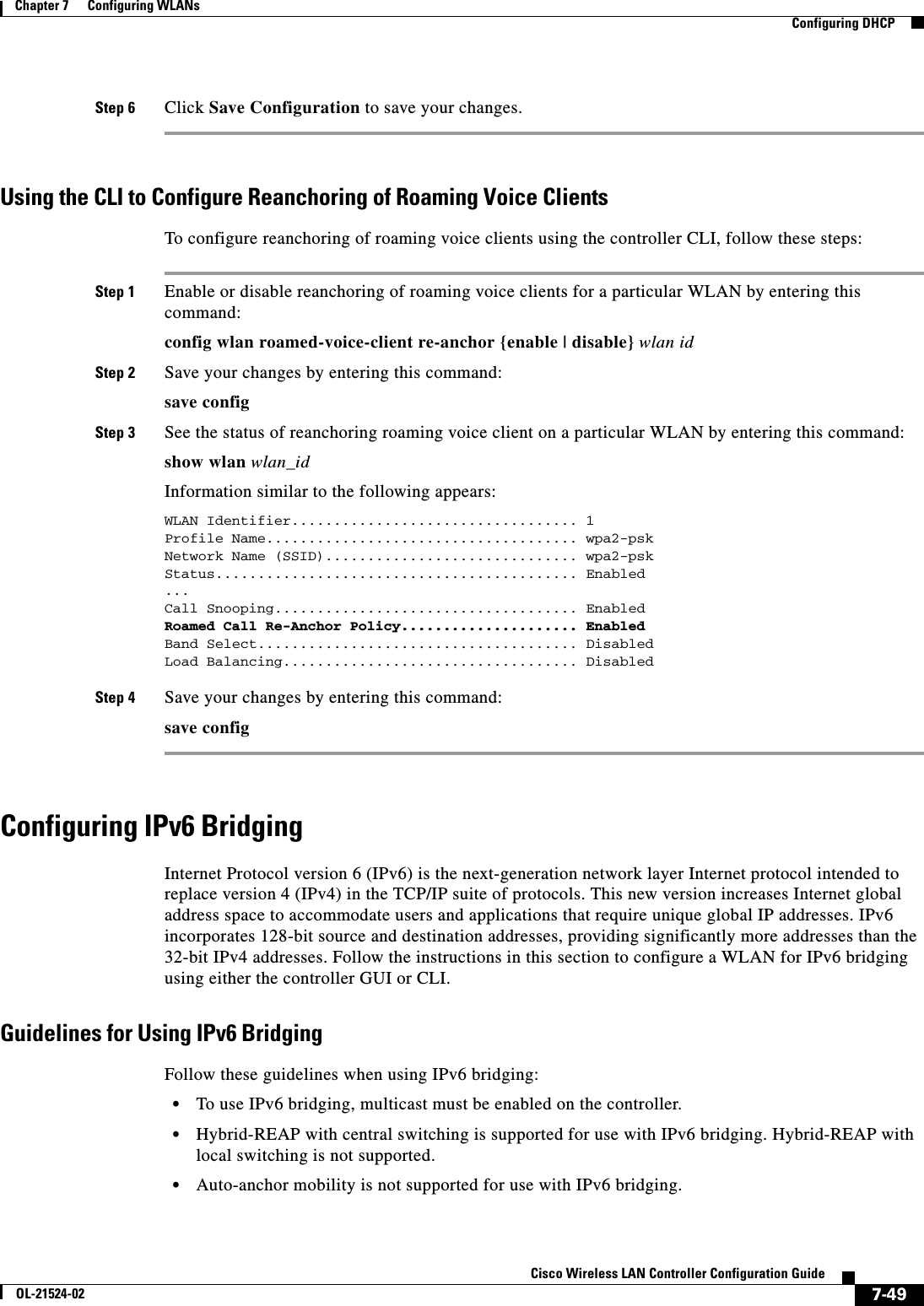
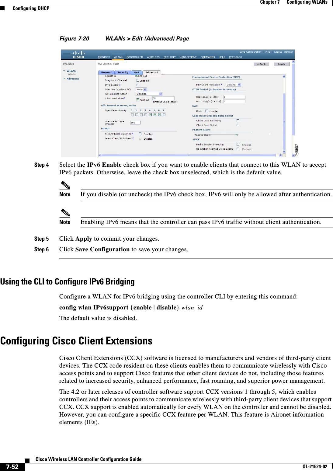
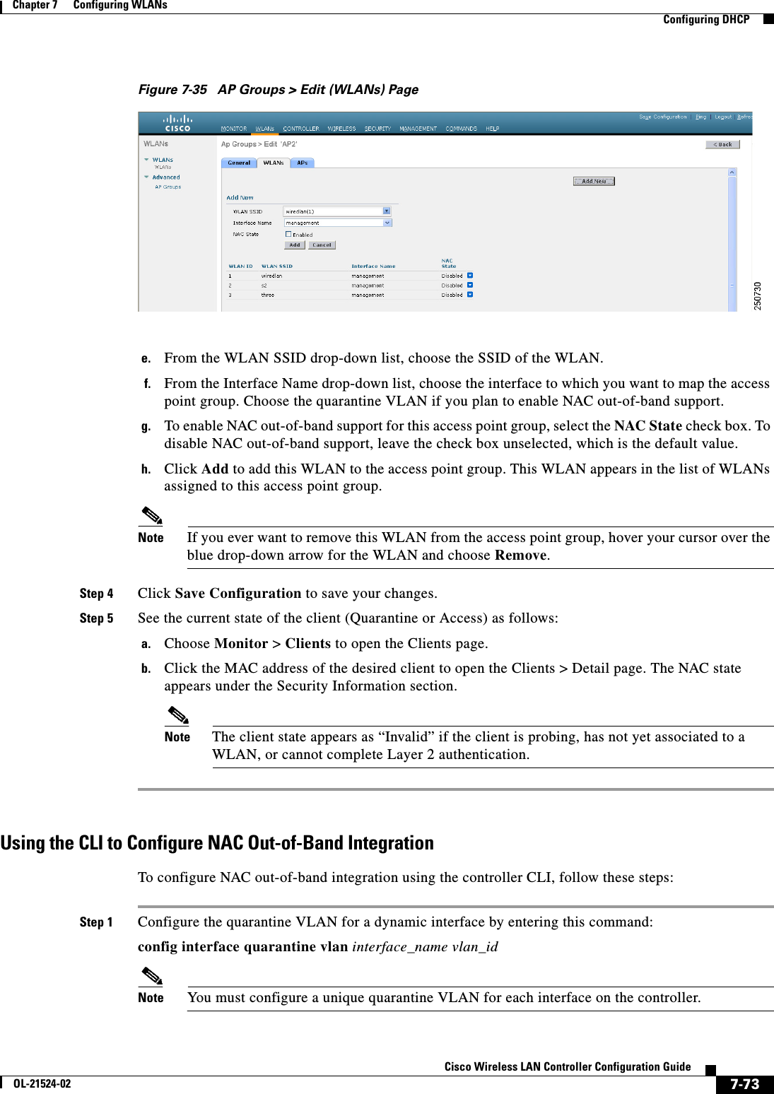
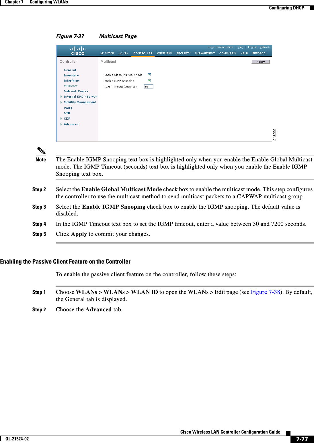
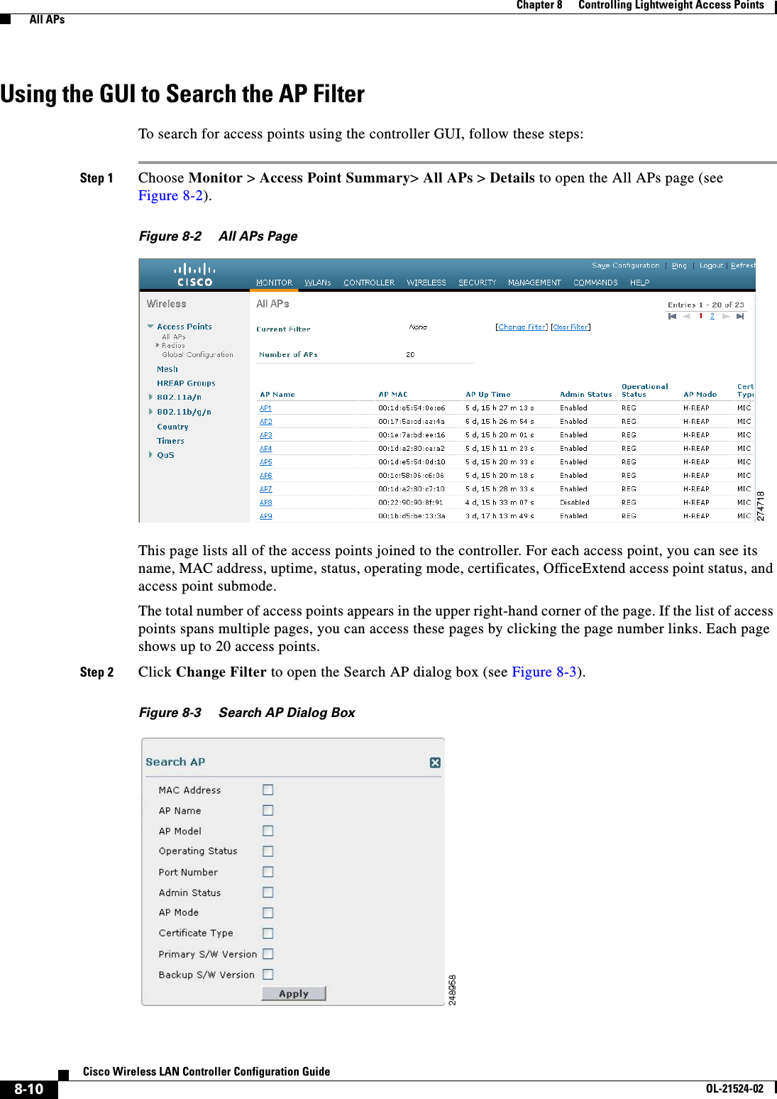
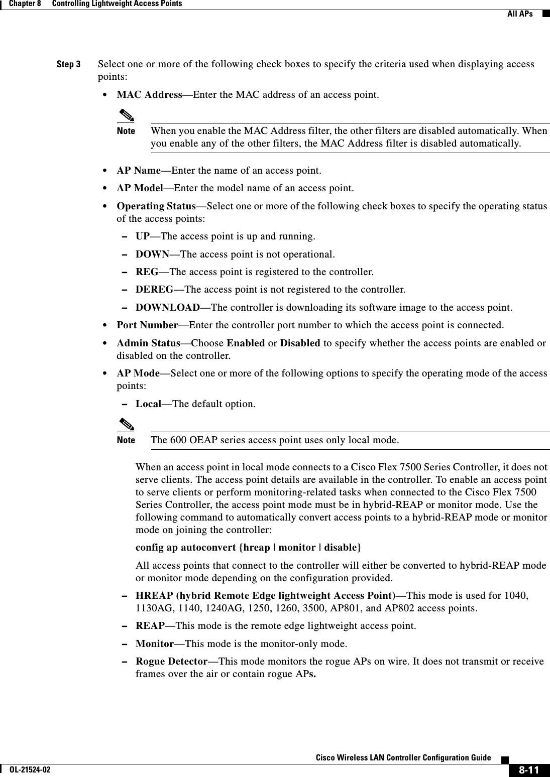
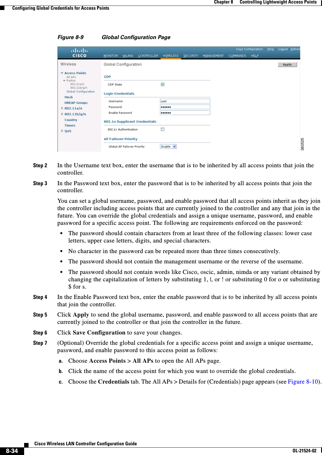
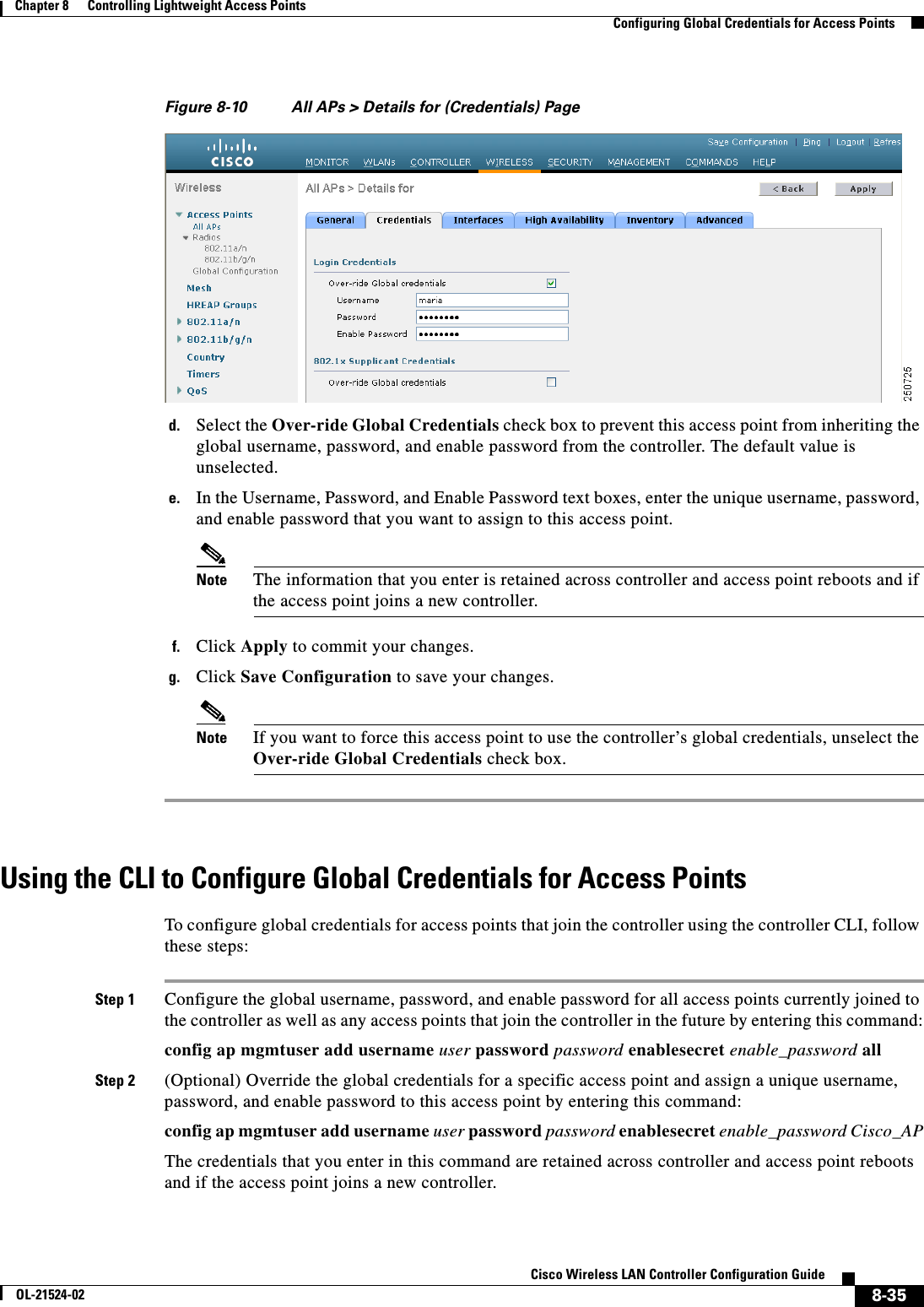
![7-16Cisco Wireless LAN Controller Configuration GuideOL-21524-02Chapter 7 Configuring WLANs Configuring DHCPStep 17 Choose DHCP Allocated Leases to see the remaining lease time for wireless clients. The DHCP Allocated Lease page appears (see Figure 7-7), showing the MAC address, IP address, and remaining lease time for the wireless clients.Figure 7-7 DHCP Allocated Lease PageUsing the CLI to Configure DHCP ScopesTo configure DHCP scopes using the controller CLI, follow these steps:Step 1 Create a new DHCP scope by entering this command:config dhcp create-scope scopeNote If you ever want to delete a DHCP scope, enter this command: config dhcp delete-scope scope.Step 2 Specify the starting and ending IP address in the range assigned to the clients by entering this command:config dhcp address-pool scope start endNote This pool must be unique for each DHCP scope and must not include the static IP addresses of routers or other servers.Step 3 Specify the network served by this DHCP scope (the IP address used by the management interface with the Netmask applied) and the subnet mask assigned to all wireless clients by entering this command:config dhcp network scope network netmaskStep 4 Specify the amount of time (from 0 to 65536 seconds) that an IP address is granted to a client by entering this command:config dhcp lease scope lease_durationStep 5 Specify the IP address of the optional router connecting the controllers by entering this command:config dhcp default-router scope router_1 [router_2] [router_3]Each router must include a DHCP forwarding agent, which allows a single controller to serve the clients of multiple controllers.Step 6 Specify the optional domain name system (DNS) domain name of this DHCP scope for use with one or more DNS servers by entering this command:config dhcp domain scope domainStep 7 Specify the IP address of the optional DNS server(s) by entering this command:](https://usermanual.wiki/Cisco-Systems/102075.Cisco-Wireless-LAN-Controller-Configuration-Guide-4/User-Guide-1514964-Page-16.png)
![7-17Cisco Wireless LAN Controller Configuration GuideOL-21524-02Chapter 7 Configuring WLANs Configuring DHCPconfig dhcp dns-servers scope dns1 [dns2] [dns3]Each DNS server must be able to update a client’s DNS entry to match the IP address assigned by this DHCP scopeStep 8 Specify the IP address of the optional Microsoft Network Basic Input Output System (NetBIOS) name server, such as the Internet Naming Service (WINS) server by entering this command:config dhcp netbios-name-server scope wins1 [wins2] [wins3]Step 9 Enable or disable this DHCP scope by entering this command:config dhcp {enable | disable} scopeStep 10 Save your changes by entering this command:save configStep 11 See the list of configured DHCP scopes by entering this command:show dhcp summaryInformation similar to the following appears:Scope Name Enabled Address RangeScope 1 No 0.0.0.0 -> 0.0.0.0Scope 2 No 0.0.0.0 -> 0.0.0.0Step 12 Display the DHCP information for a particular scope by entering this command:show dhcp scopeInformation similar to the following appears:Enabled....................................... NoLease Time.................................... 0Pool Start.................................... 0.0.0.0Pool End...................................... 0.0.0.0Network....................................... 0.0.0.0Netmask....................................... 0.0.0.0Default Routers............................... 0.0.0.0 0.0.0.0 0.0.0.0DNS Domain.................................... DNS........................................... 0.0.0.0 0.0.0.0 0.0.0.0Netbios Name Servers.......................... 0.0.0.0 0.0.0.0 0.0.0.0Configuring MAC Filtering for WLANsWhen you use MAC filtering for client or administrator authorization, you need to enable it at the WLAN level first. If you plan to use local MAC address filtering for any WLAN, use the commands in this section to configure MAC filtering for a WLAN.Enabling MAC FilteringUse these commands to enable MAC filtering on a WLAN: • Enable MAC filtering by entering the config wlan mac-filtering enable wlan_id command. • Verify that you have MAC filtering enabled for the WLAN by entering the show wlan command.When you enable MAC filtering, only the MAC addresses that you add to the WLAN are allowed to join the WLAN. MAC addresses that have not been added are not allowed to join the WLAN.](https://usermanual.wiki/Cisco-Systems/102075.Cisco-Wireless-LAN-Controller-Configuration-Guide-4/User-Guide-1514964-Page-17.png)
![7-18Cisco Wireless LAN Controller Configuration GuideOL-21524-02Chapter 7 Configuring WLANs Configuring DHCPCreating a Local MAC FilterControllers have built-in MAC filtering capability, similar to that provided by a RADIUS authorization server.Use these commands to add MAC addresses to a WLAN MAC filter: • Create a MAC filter entry on the controller by entering the config macfilter add mac_addr wlan_id [interface_name] [description] [IP_addr] command.The following parameters are optional: –mac_addr—MAC address of the client. –wlan_id—WLAN id on which the client is associating. –interface_name—The name of the interface. This interface name is used to override the interface configured to the WLAN.Note You must have AAA enabled on the WLAN to override the interface name. –description—A brief description of the interface in double quotes (for example, “Interface1”). –IP_addr—The IP address which is used for a passive client with the MAC address specified by the mac addr value above. • Assign an IP address to an existing MAC filter entry, if one was not assigned in the config macfilter add command by entering the config macfilter ip-address mac_addr IP_addr command. • Verify that MAC addresses are assigned to the WLAN by entering the show macfilter command.Configuring a Timeout for Disabled ClientsYou can configure a timeout for disabled clients. Clients who fail to authenticate three times when attempting to associate are automatically disabled from further association attempts. After the timeout period expires, the client is allowed to retry authentication until it associates or fails authentication and is excluded again. Use these commands to configure a timeout for disabled clients: • Configure the timeout for disabled clients by entering the config wlan exclusionlist wlan_id timeout command. Enter a timeout from 1 to 65535 seconds, or enter 0 to permanently disable the client. • Verify the current timeout by entering the show wlan command.Assigning WLANs to InterfacesUse these commands to assign a WLAN to an interface: • Assign a WLAN to an interface by entering this command:config wlan interface {wlan_id | foreignAp} interface_id –Use the interface_id option to assign the WLAN to a specific interface. –Use the foreignAp option to use a third-party access point. • Verify the interface assignment status by entering the show wlan summary command.](https://usermanual.wiki/Cisco-Systems/102075.Cisco-Wireless-LAN-Controller-Configuration-Guide-4/User-Guide-1514964-Page-18.png)
![7-25Cisco Wireless LAN Controller Configuration GuideOL-21524-02Chapter 7 Configuring WLANs Configuring DHCPconfig wlan security 802.1X {enable | disable} wlan_idAfter you enable 802.1X authentication, the controller sends EAP authentication packets between the wireless client and the authentication server. This command allows all EAP-type packets to be sent to and from the controller. • Change the 802.1X encryption level for a WLAN by entering this command:config wlan security 802.1X encryption wlan_id [0 | 40 | 104] –Use the 0 option to specify no 802.1X encryption. –Use the 40 option to specify 40/64-bit encryption. –Use the 104 option to specify 104/128-bit encryption. (This is the default encryption setting.)Configuring a WLAN for Both Static and Dynamic WEPYou can configure up to four WLANs to support static WEP keys, and you can also configure dynamic WEP on any of these static-WEP WLANs. Follow these guidelines when configuring a WLAN for both static and dynamic WEP: • The static WEP key and the dynamic WEP key must be the same length. • When you configure both static and dynamic WEP as the Layer 2 security policy, no other security policies can be specified. That is, you cannot configure web authentication. However, when you configure either static or dynamic WEP as the Layer 2 security policy, you can configure web authentication.WPA1 and WPA2Wi-Fi Protected Access (WPA or WPA1) and WPA2 are standards-based security solutions from the Wi-Fi Alliance that provide data protection and access control for wireless LAN systems. WPA1 is compatible with the IEEE 802.11i standard but was implemented prior to the standard’s ratification; WPA2 is the Wi-Fi Alliance's implementation of the ratified IEEE 802.11i standard. By default, WPA1 uses Temporal Key Integrity Protocol (TKIP) and message integrity check (MIC) for data protection while WPA2 uses the stronger Advanced Encryption Standard encryption algorithm using Counter Mode with Cipher Block Chaining Message Authentication Code Protocol (AES-CCMP). Both WPA1 and WPA2 use 802.1X for authenticated key management by default. However, these options are also available: • 802.1X—The standard for wireless LAN security, as defined by IEEE, is called 802.1X for 802.11, or simply 802.1X. An access point that supports 802.1X acts as the interface between a wireless client and an authentication server, such as a RADIUS server, to which the access point communicates over the wired network. If 802.1X is selected, only 802.1X clients are supported. • PSK—When you choose PSK (also known as WPA preshared key or WPA passphrase), you need to configure a preshared key (or a passphrase). This key is used as the pairwise master key (PMK) between the clients and the authentication server. • CCKM—Cisco Centralized Key Management (CCKM) uses a fast rekeying technique that enables clients to roam from one access point to another without going through the controller, typically in under 150 milliseconds (ms). CCKM reduces the time required by the client to mutually authenticate with the new access point and derive a new session key during reassociation. CCKM fast secure roaming ensures that there is no perceptible delay in time-sensitive applications such as wireless Voice over IP (VoIP), enterprise resource planning (ERP), or Citrix-based solutions. CCKM is a CCXv4-compliant feature. If CCKM is selected, only CCKM clients are supported.](https://usermanual.wiki/Cisco-Systems/102075.Cisco-Wireless-LAN-Controller-Configuration-Guide-4/User-Guide-1514964-Page-25.png)
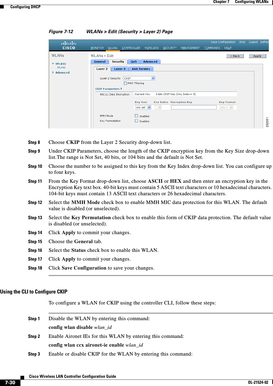
![7-29Cisco Wireless LAN Controller Configuration GuideOL-21524-02Chapter 7 Configuring WLANs Configuring DHCPCKIPCisco Key Integrity Protocol (CKIP) is a Cisco-proprietary security protocol for encrypting 802.11 media. CKIP improves 802.11 security in infrastructure mode using key permutation, a message integrity check (MIC), and a message sequence number. Software release 4.0 or later releases support CKIP with a static key. For this feature to operate correctly, you must enable Aironet information elements (IEs) for the WLAN.A lightweight access point advertises support for CKIP in beacon and probe response packets by adding an Aironet IE and setting one or both of the CKIP negotiation bits (key permutation and multi-modular hash message integrity check [MMH MIC]). Key permutation is a data encryption technique that uses the basic encryption key and the current initialization vector (IV) to create a new key. MMH MIC prevents bit-flip attacks on encrypted packets by using a hash function to compute message integrity code.The CKIP settings specified in a WLAN are mandatory for any client attempting to associate. If the WLAN is configured for both CKIP key permutation and MMH MIC, the client must support both. If the WLAN is configured for only one of these features, the client must support only the CKIP feature.CKIP requires that 5-byte and 13-byte encryption keys be expanded to 16-byte keys. The algorithm to perform key expansion occurs at the access point. The key is appended to itself repeatedly until the length reaches 16 bytes. All lightweight access points support CKIP.You can configure CKIP through either the GUI or the CLI.Using the GUI to Configure CKIPTo configure a WLAN for CKIP using the controller GUI, follow these steps:Step 1 Choose WLANs to open the WLANs page.Step 2 Click the ID number of the desired WLAN to open the WLANs > Edit page.Step 3 Choose the Advanced tab.Step 4 Select the Aironet IE check box to enable Aironet IEs for this WLAN and click Apply.Step 5 Choose the General tab.Step 6 Unselect the Status check box, if selected, to disable this WLAN and click Apply.Step 7 Choose the Security and Layer 2 tabs to open the WLANs > Edit (Security > Layer 2) page (see Figure 7-12).](https://usermanual.wiki/Cisco-Systems/102075.Cisco-Wireless-LAN-Controller-Configuration-Guide-4/User-Guide-1514964-Page-29.png)
![7-64Cisco Wireless LAN Controller Configuration GuideOL-21524-02Chapter 7 Configuring WLANs Configuring DHCPFigure 7-27 ACS Server ConfigurationStep 4 Select the [009\001] cisco-av-pair check box.Step 5 Enter the following Cisco AV-pairs in the [009\001] cisco-av-pair edit box to specify the URL to which the user is redirected and, if configuring conditional web redirect, the conditions under which the redirect takes place, respectively:url-redirect=http://urlurl-redirect-acl=acl_nameUsing the GUI to Configure Web RedirectTo configure conditional or splash page web redirect using the controller GUI, follow these steps:Step 1 Choose WLANs to open the WLANs page.Step 2 Click the ID number of the desired WLAN. The WLANs > Edit page appears.Step 3 Choose the Security and Layer 2 tabs to open the WLANs > Edit (Security > Layer 2) page.](https://usermanual.wiki/Cisco-Systems/102075.Cisco-Wireless-LAN-Controller-Configuration-Guide-4/User-Guide-1514964-Page-64.png)

![8-45Cisco Wireless LAN Controller Configuration GuideOL-21524-02Chapter 8 Controlling Lightweight Access Points Autonomous Access Points Converted to Lightweight ModeStep 3 Wait until the access point reboots and reconfigure the access point using the CLI or GUI.Using the MODE Button and a TFTP Server to Return to a Previous ReleaseTo revert from lightweight mode to autonomous mode by using the access point MODE (reset) button to load a Cisco IOS release from a TFTP server, follow these steps:Step 1 Configure the PC on which your TFTP server software runs with a static IP address in the range of 10.0.0.2 to 10.0.0.30.Step 2 Make sure that the PC contains the access point image file (such as c1200-k9w7-tar.123-7.JA.tar for a 1200 series access point) in the TFTP server folder and that the TFTP server is activated. Step 3 Rename the access point image file in the TFTP server folder to c1200-k9w7-tar.default for a 1200 series access point.Step 4 Connect the PC to the access point using a Category 5 (CAT5) Ethernet cable.Step 5 Disconnect power from the access point.Step 6 Press and hold the MODE button while you reconnect power to the access point.Note The MODE button on the access point must be enabled. Follow the steps in the “Disabling the Reset Button on Access Points Converted to Lightweight Mode” section on page 8-66 to select the status of the access point MODE button.Step 7 Hold the MODE button until the status LED turns red (approximately 20 to 30 seconds), and release the MODE button.Step 8 Wait until the access point reboots as indicated by all LEDs turning green followed by the Status LED blinking green.Step 9 After the access point reboots, reconfigure the access point using the GUI or the CLI.Authorizing Access PointsIn controller software releases prior to 5.2, the controller may either use self-signed certificates (SSCs) to authenticate access points or send the authorization information to a RADIUS server (if access points have manufactured-installed certificates [MICs]). In controller software release 5.2 or later releases, you can configure the controller to use a local significant certificate (LSC).Authorizing Access Points Using SSCsThe Control and Provisioning of Wireless Access Points protocol (CAPWAP) secures the control communication between the access point and controller by a secure key distribution requiring X.509 certificates on both the access point and controller. CAPWAP relies on provisioning of the X.509 certificates. Cisco Aironet access points shipped before July 18, 2005 do not have a MIC, so these access points create an SSC when upgraded to operate in lightweight mode. Controllers are programmed to accept local SSCs for authentication of specific access points and do not forward those authentication requests to a RADIUS server. This behavior is acceptable and secure.](https://usermanual.wiki/Cisco-Systems/102075.Cisco-Wireless-LAN-Controller-Configuration-Guide-4/User-Guide-1514964-Page-129.png)
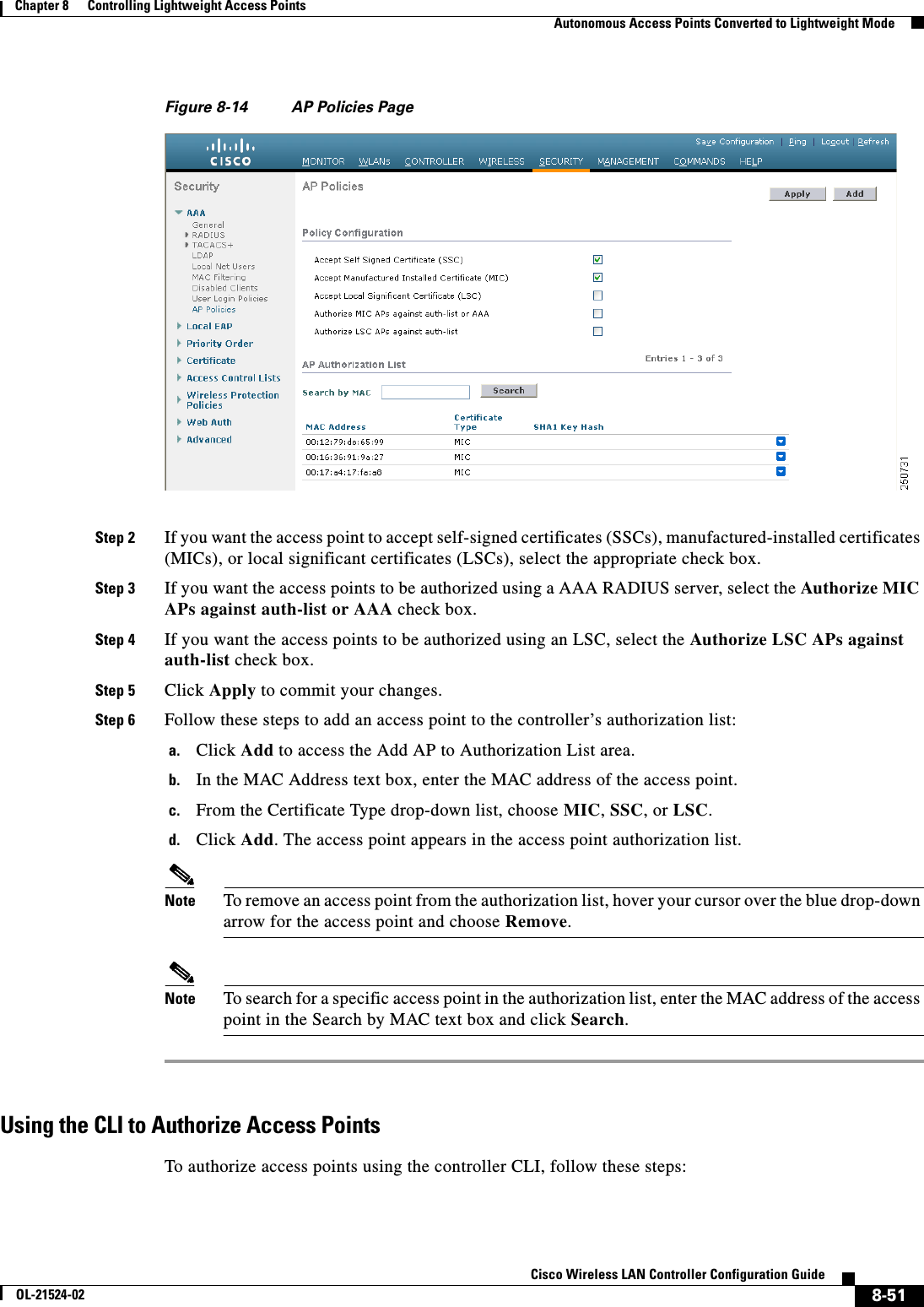
![8-52Cisco Wireless LAN Controller Configuration GuideOL-21524-02Chapter 8 Controlling Lightweight Access Points Autonomous Access Points Converted to Lightweight ModeStep 1 Configure an access point authorization policy by entering this command: config auth-list ap-policy {authorize-ap {enable | disable} | authorize-lsc-ap {enable | disable}} Step 2 Configure an access point to accept manufactured-installed certificates (MICs), self-signed certificates (SSCs), or local significant certificates (LSCs) by entering this command:config auth-list ap-policy {mic | ssc | lsc {enable | disable}}Step 3 Add an access point to the authorization list by entering this command:config auth-list add {mic | ssc | lsc} ap_mac [ap_key]where ap_key is an optional key hash value equal to 20 bytes or 40 digits. Note To delete an access point from the authorization list, enter this command: config auth-list delete ap_mac.Step 4 See the access point authorization list by entering this command:show auth-listInformation similar to the following appears:Authorize MIC APs against AAA ....................... disabledAuthorize LSC APs against Auth-List ................. disabledAllow APs with MIC - Manufactured Installed C ....... enabledAllow APs with SSC - Self-Signed Certificate ........ enabledAllow APs with LSC - Locally Significant Cert ....... enabledMac Addr Cert Type Key Hash----------------------- ---------- ---------------------------------------------00:12:79:de:65:99 SSC ca528236137130d37049a5ef3d1983b30ad7e54300:16:36:91:9a:27 MIC 593f34e7cb151997a28cc7da2a6cac040b329636 Using DHCP Option 43 and DHCP Option 60Cisco Aironet access points use the type-length-value (TLV) format for DHCP option 43. DHCP servers must be programmed to return the option based on the access point’s DHCP Vendor Class Identifier (VCI) string (DHCP option 60). Table 8-19 lists the VCI strings for Cisco access points capable of operating in lightweight mode.Ta b l e 8-19 VCI Strings For Lightweight Access Points Access Point VCI StringCisco Aironet 1130 Series Cisco AP c1130Cisco Aironet 1140 Series Cisco AP c1140Cisco Aironet 1200 Series Cisco AP c1200Cisco Aironet 1240 Series Cisco AP c1240Cisco Aironet 1250 Series Cisco AP c1250Cisco Aironet 1260 Series Cisco AP c1260](https://usermanual.wiki/Cisco-Systems/102075.Cisco-Wireless-LAN-Controller-Configuration-Guide-4/User-Guide-1514964-Page-136.png)