Cisco Systems 102075 Cisco Aironet 802.11n Dual Band Access Points User Manual Cisco Wireless LAN Controller Configuration Guide 6
Cisco Systems Inc Cisco Aironet 802.11n Dual Band Access Points Cisco Wireless LAN Controller Configuration Guide 6
Contents
- 1. User manual
- 2. Cisco Wireless LAN Controller Configuration Guide_1
- 3. Cisco Wireless LAN Controller Configuration Guide_2
- 4. Cisco Wireless LAN Controller Configuration Guide_3
- 5. Cisco Wireless LAN Controller Configuration Guide_4
- 6. Cisco Wireless LAN Controller Configuration Guide_5
- 7. Cisco Wireless LAN Controller Configuration Guide_6
- 8. Cisco Wireless LAN Controller Configuration Guide_7
- 9. Cisco Wireless LAN Controller Configuration Guide_8
- 10. Cisco Wireless LAN Controller Configuration Guide_9
- 11. Cisco Wireless LAN Controller Configuration Guide_10
- 12. Cisco Wireless LAN Controller Configuration Guide_11
- 13. User Manual
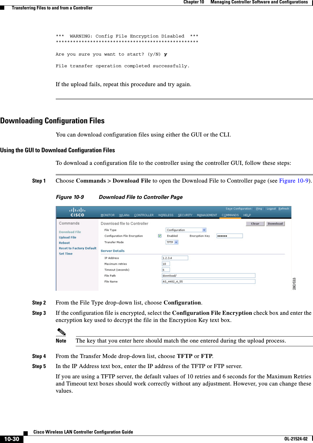
Cisco Wireless LAN Controller Configuration Guide_6
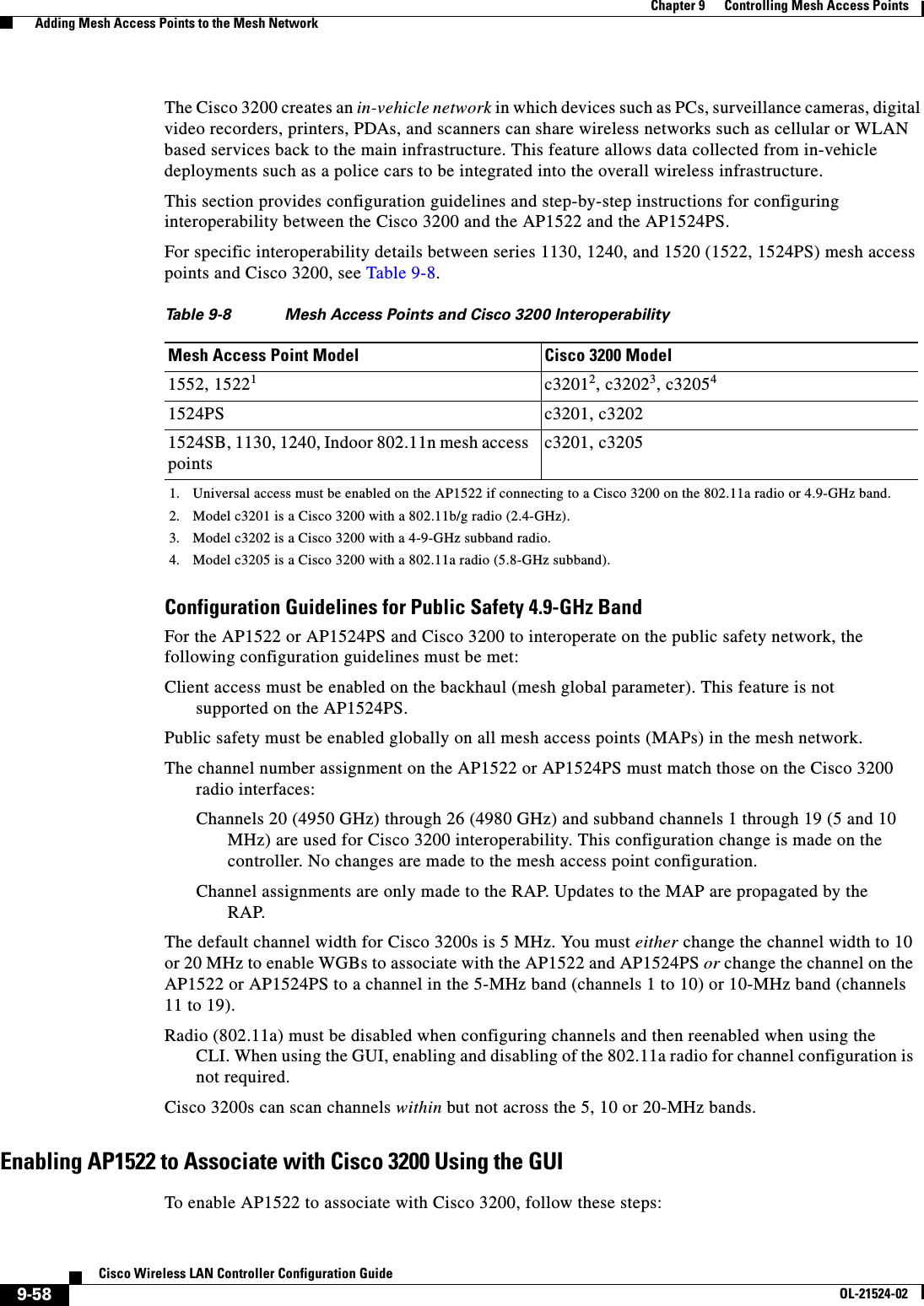
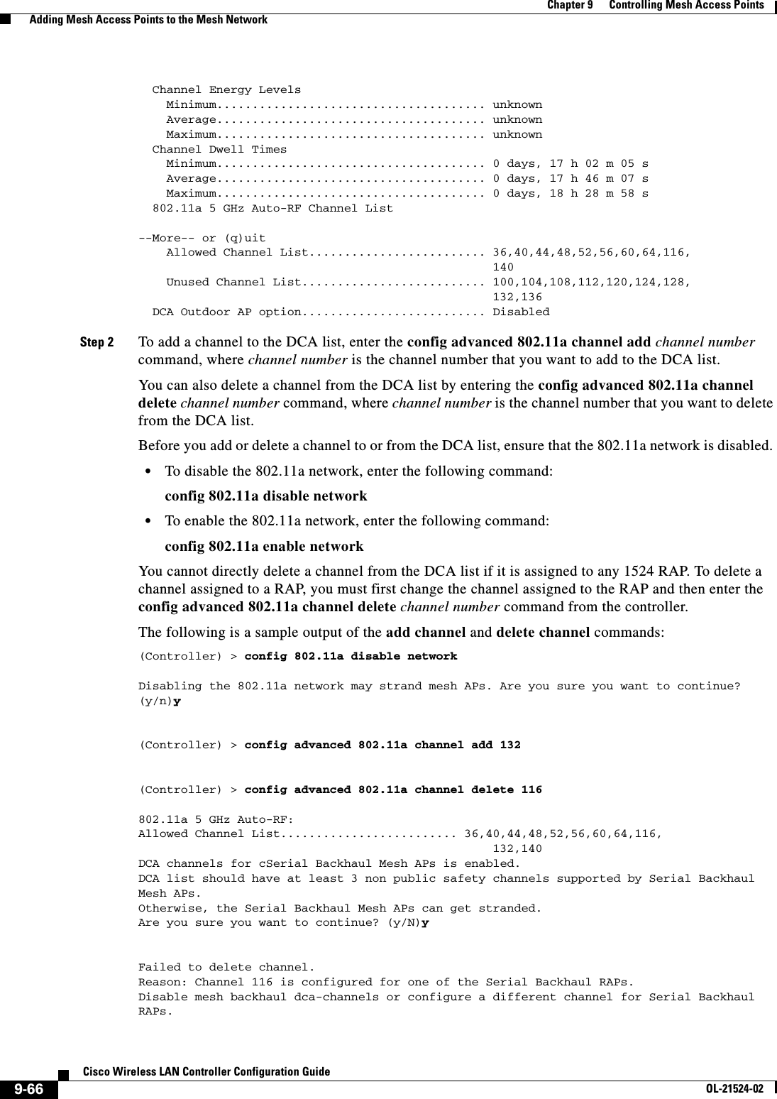
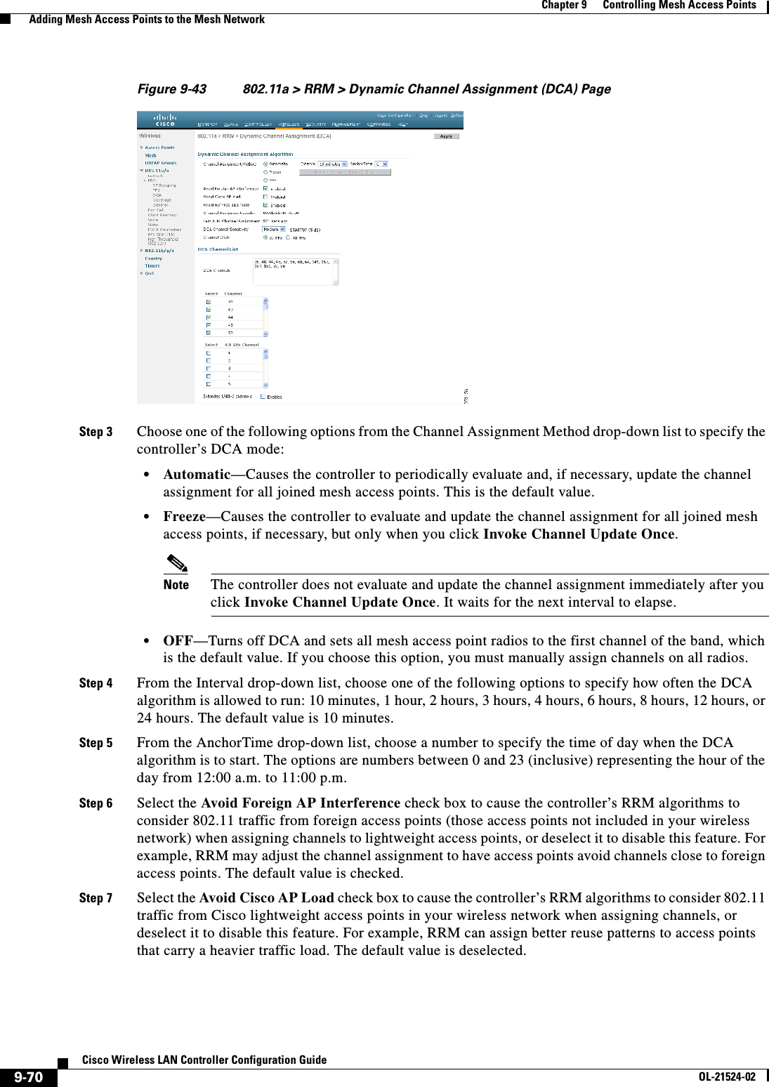
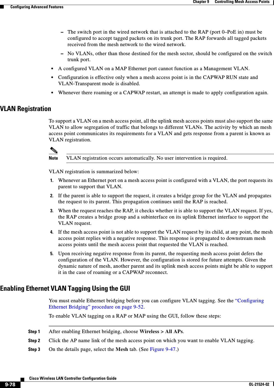
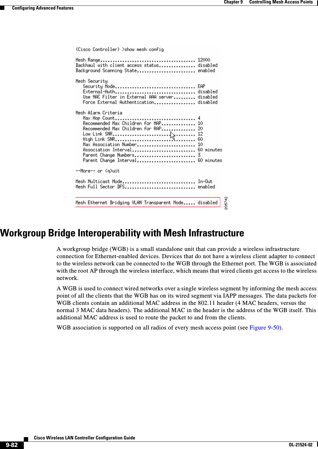
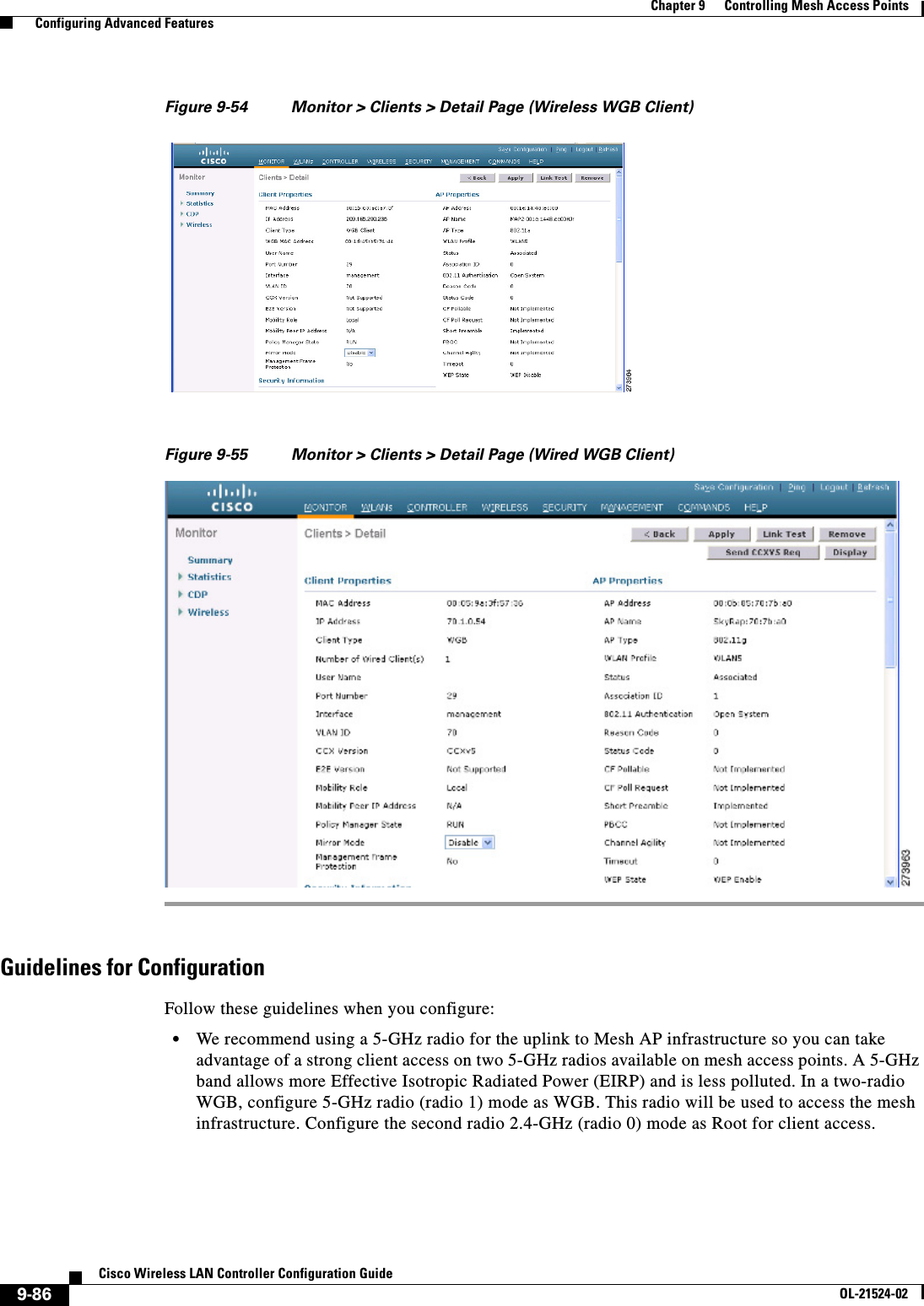
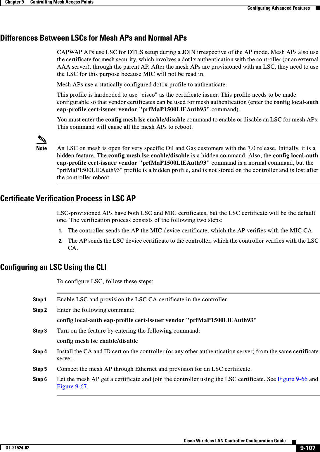
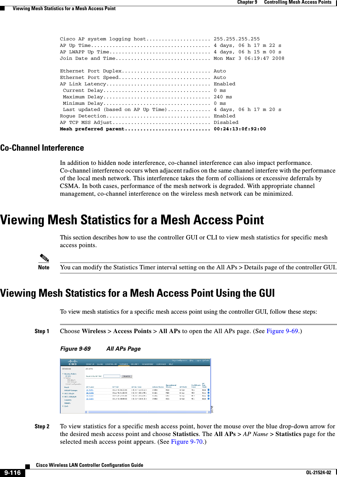
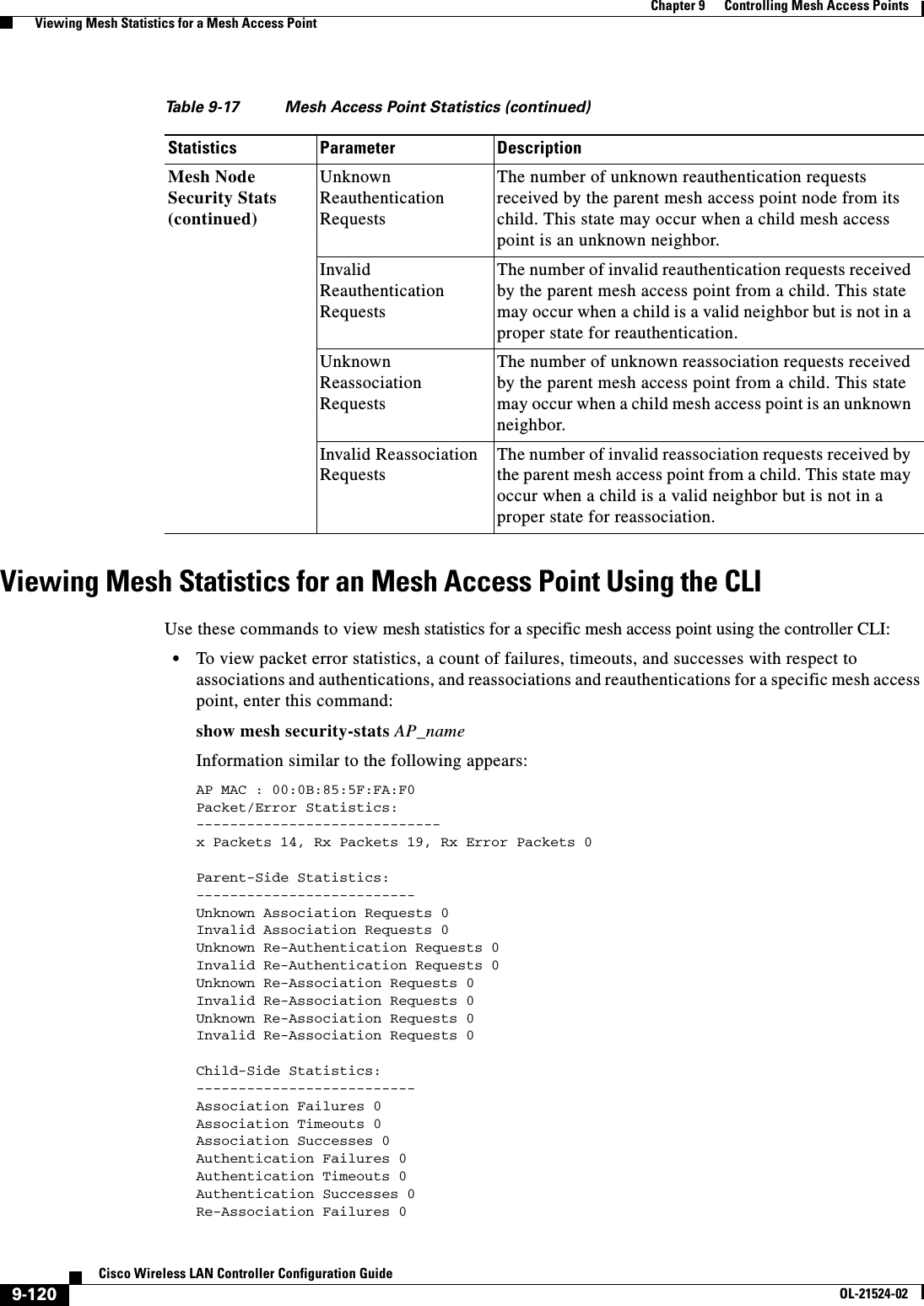
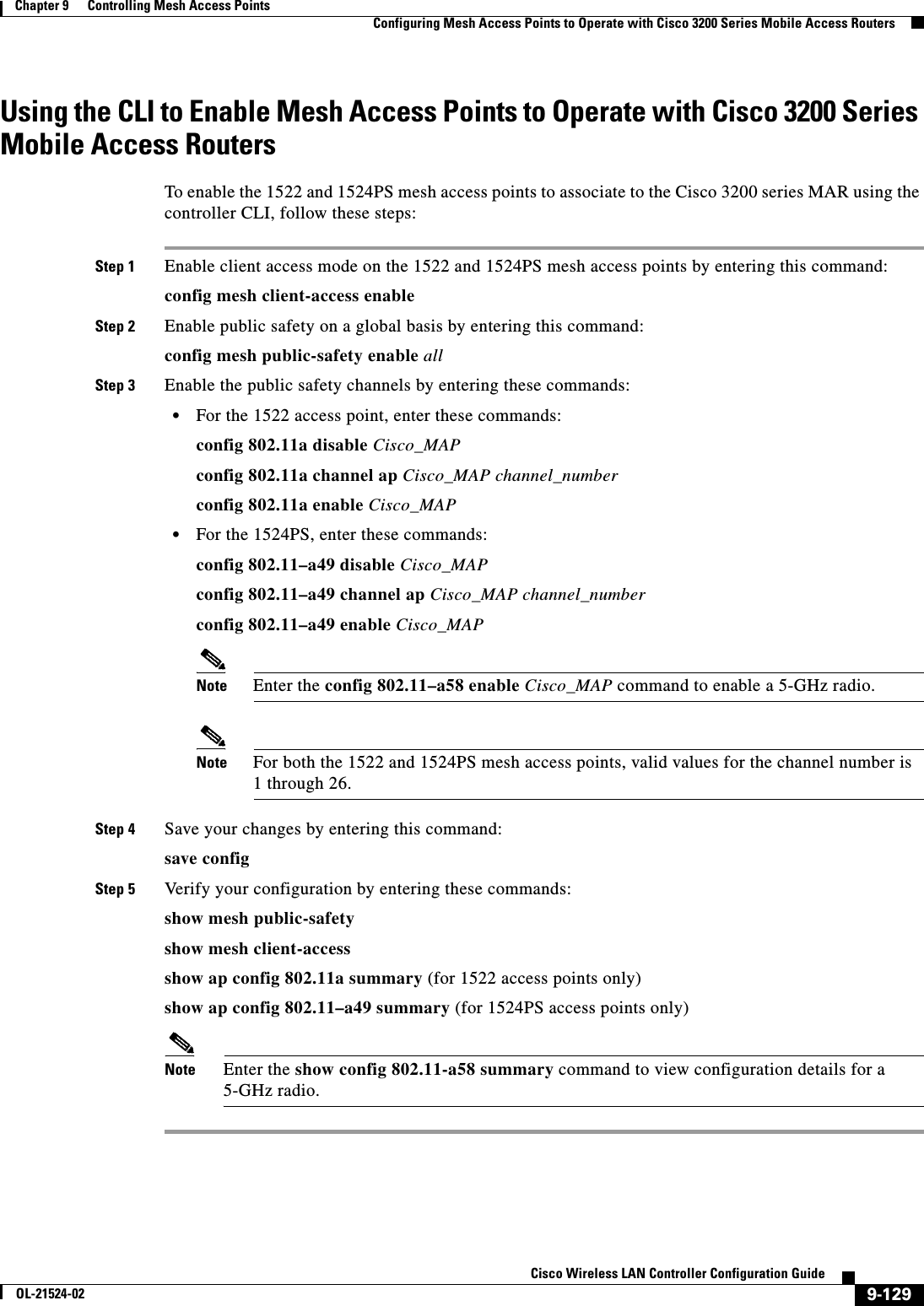
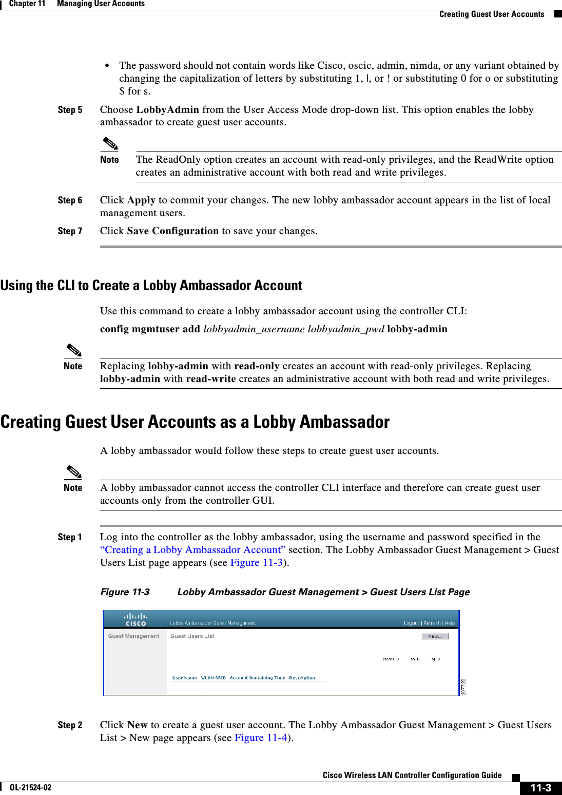
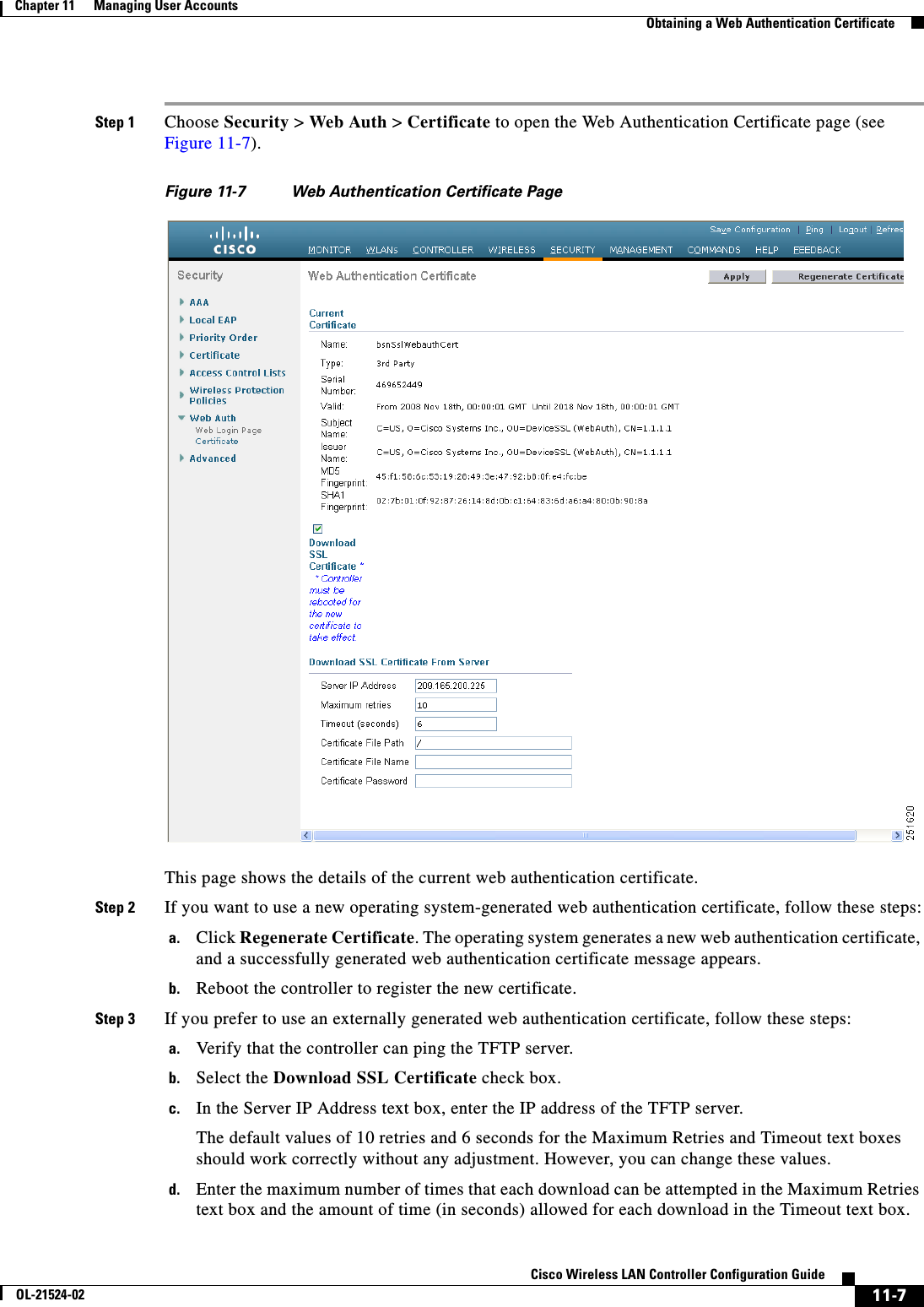
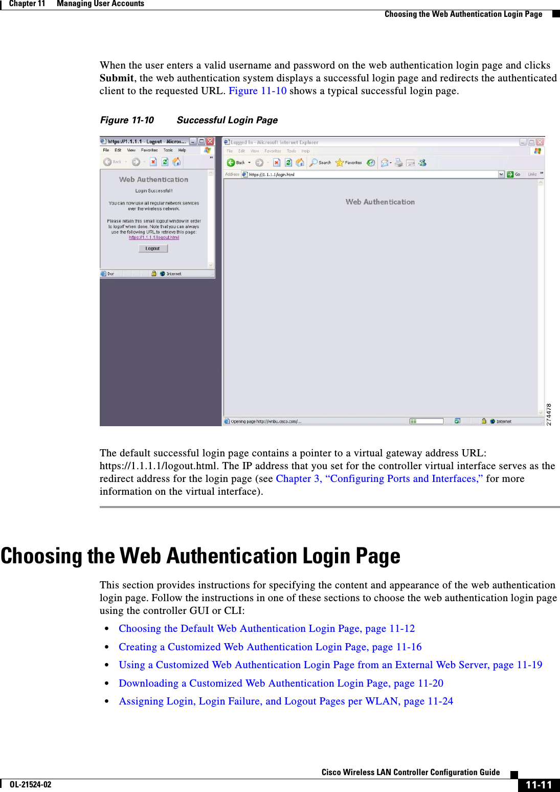
![9-88Cisco Wireless LAN Controller Configuration GuideOL-21524-02Chapter 9 Controlling Mesh Access Points Configuring Advanced FeaturesWGB1(config-subif)#bridge-group 1WGB1(config-subif)#exitWGB1(config)#interface Dot11Radio0.51WGB1(config-subif)#encapsulation dot1q 51 nativeWGB1(config-subif)#bridge-group 1WGB1(config-subif)#exitWGB1(config)#dot11 ssid WGBTESTWGB1(config-ssid)#VLAN 51WGB1(config-ssid)#authentication openWGB1(config-ssid)#infrastructiure-ssidWGB1(config-ssid)#exitWGB1(config)#interface Dot11Radio1WGB1(config-if)#ssid WGBTESTWGB1(config-if)#station-role workgroup-bridgeWGB1(config-if)#exitWGB1(config)#interface Dot11Radio0WGB1(config-if)#ssid WGBTEST WGB1(config-if)#station-role rootWGB1(config-if)#exitYou can also use the GUI of an autonomous AP for configuration (see Figure 9-56). From the GUI, subinterfaces are automatically created after the VLAN is defined.Figure 9-56 SSID Configuration PageWGB Association CheckBoth the WGB association to the controller and the wireless client association to WGB can be verified by entering the show dot11 associations client command in autonomous AP.WGB#show dot11 associations client802.11 Client Stations on Dot11Radio1: SSID [WGBTEST] : MAC Address IP Address Device Name Parent State0024.130f.920e 209.165.200.225LWAPP-ParentRAPSB -Assoc](https://usermanual.wiki/Cisco-Systems/102075.Cisco-Wireless-LAN-Controller-Configuration-Guide-6/User-Guide-1514966-Page-34.png)
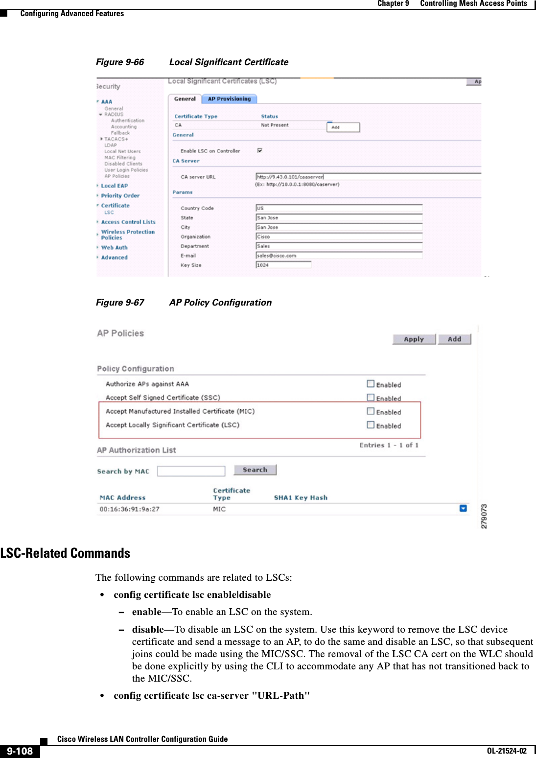

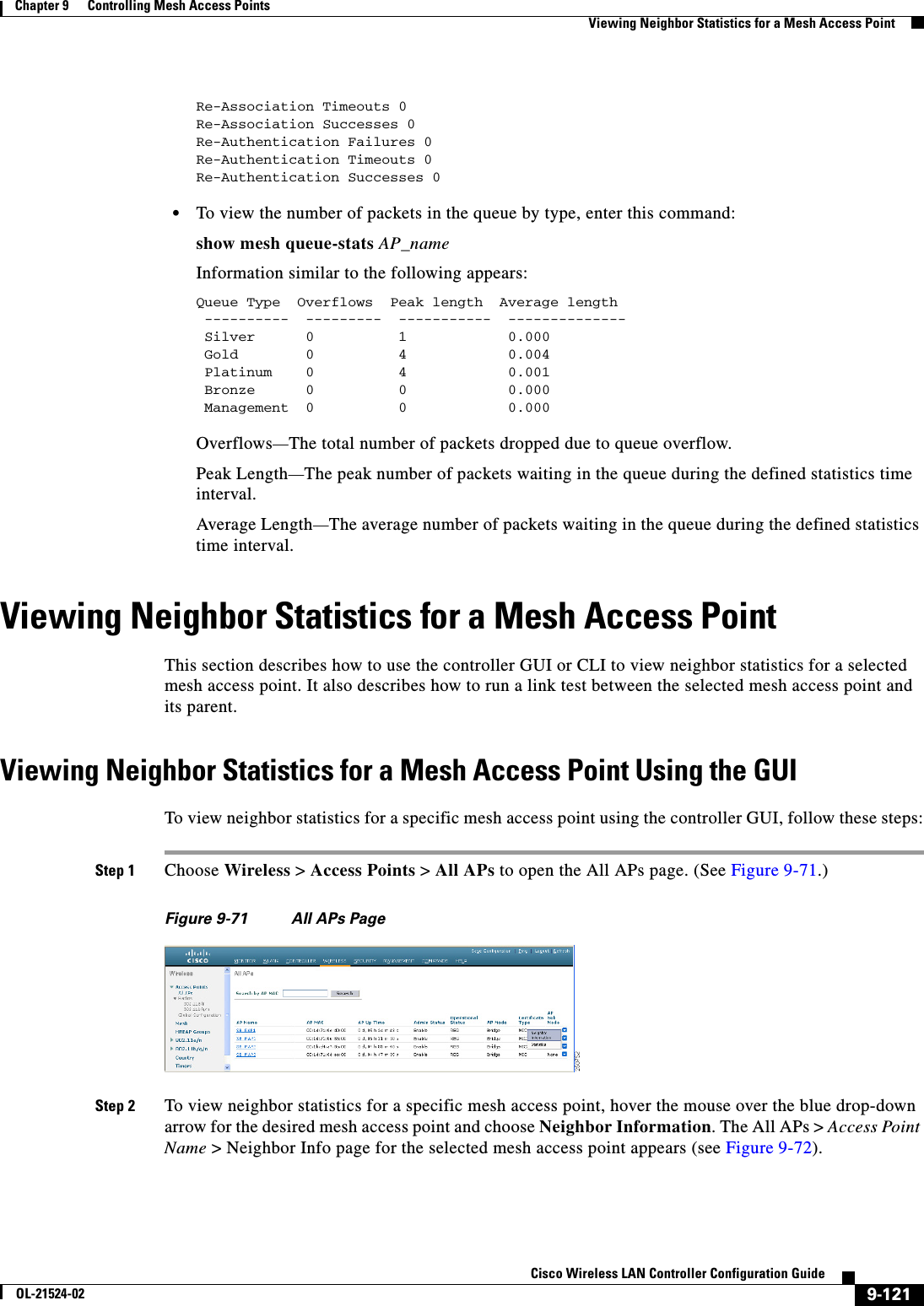


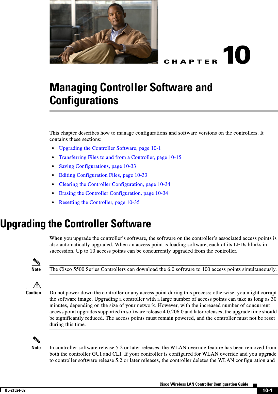

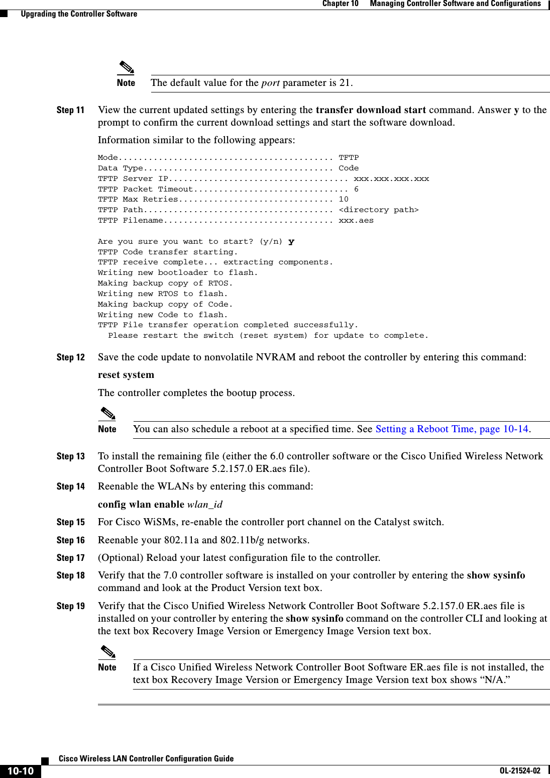
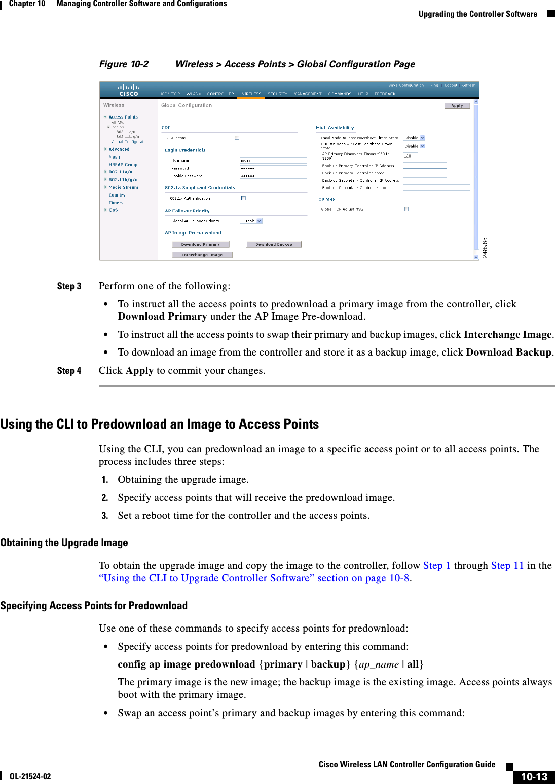
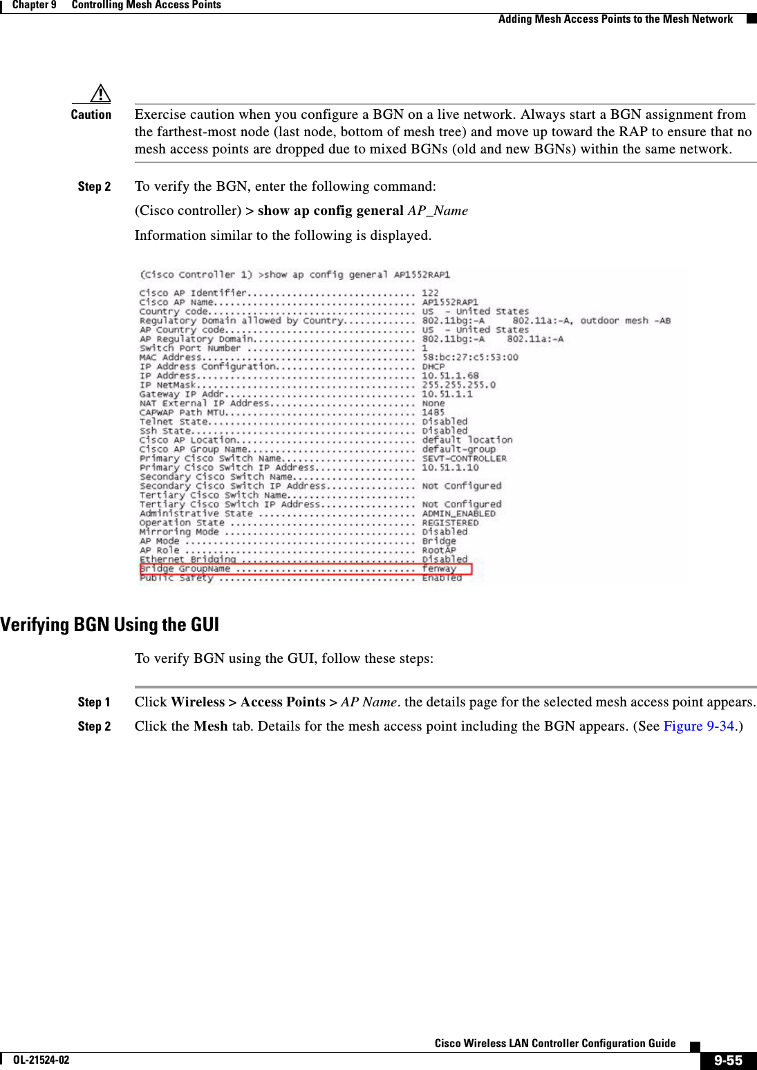
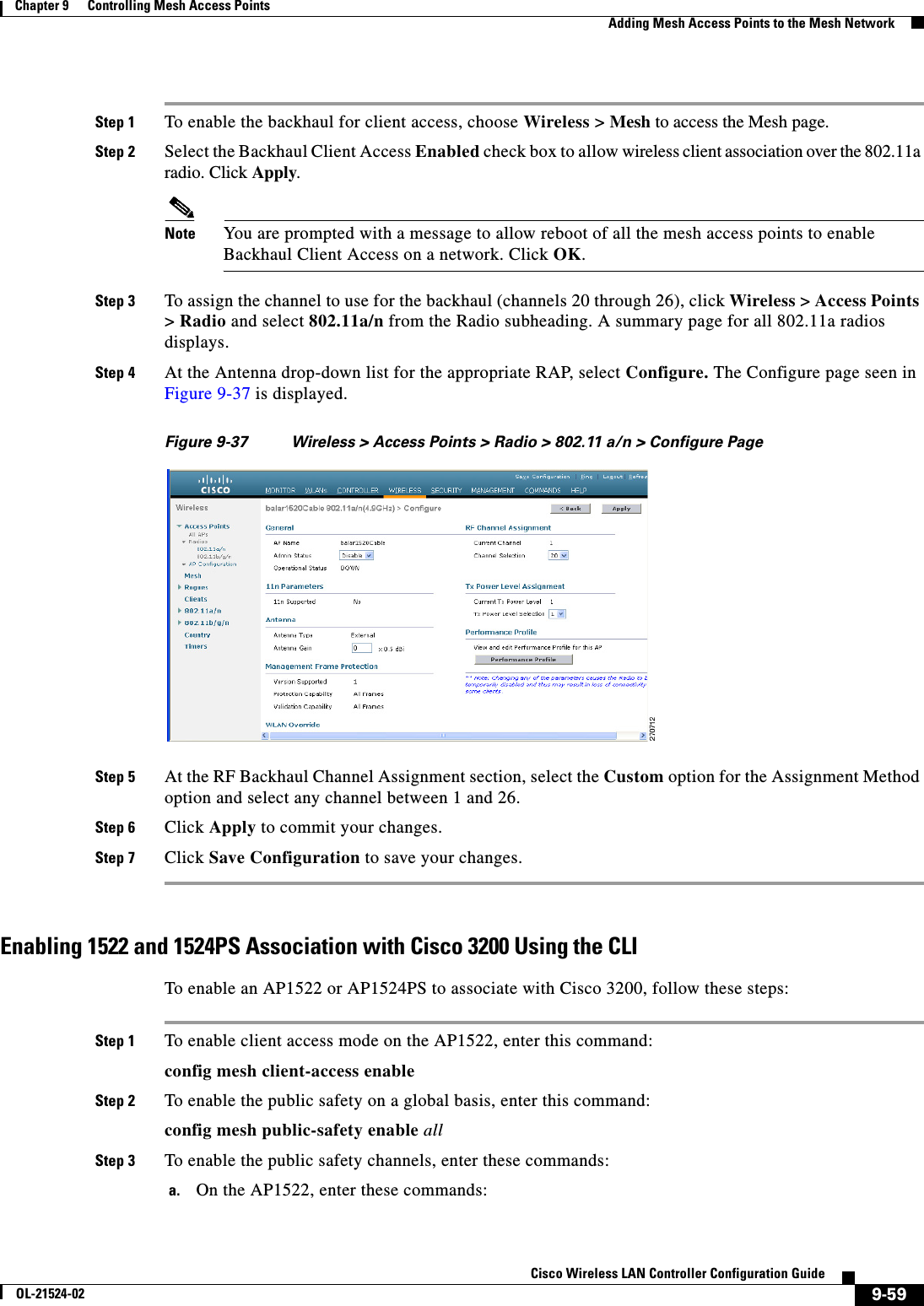
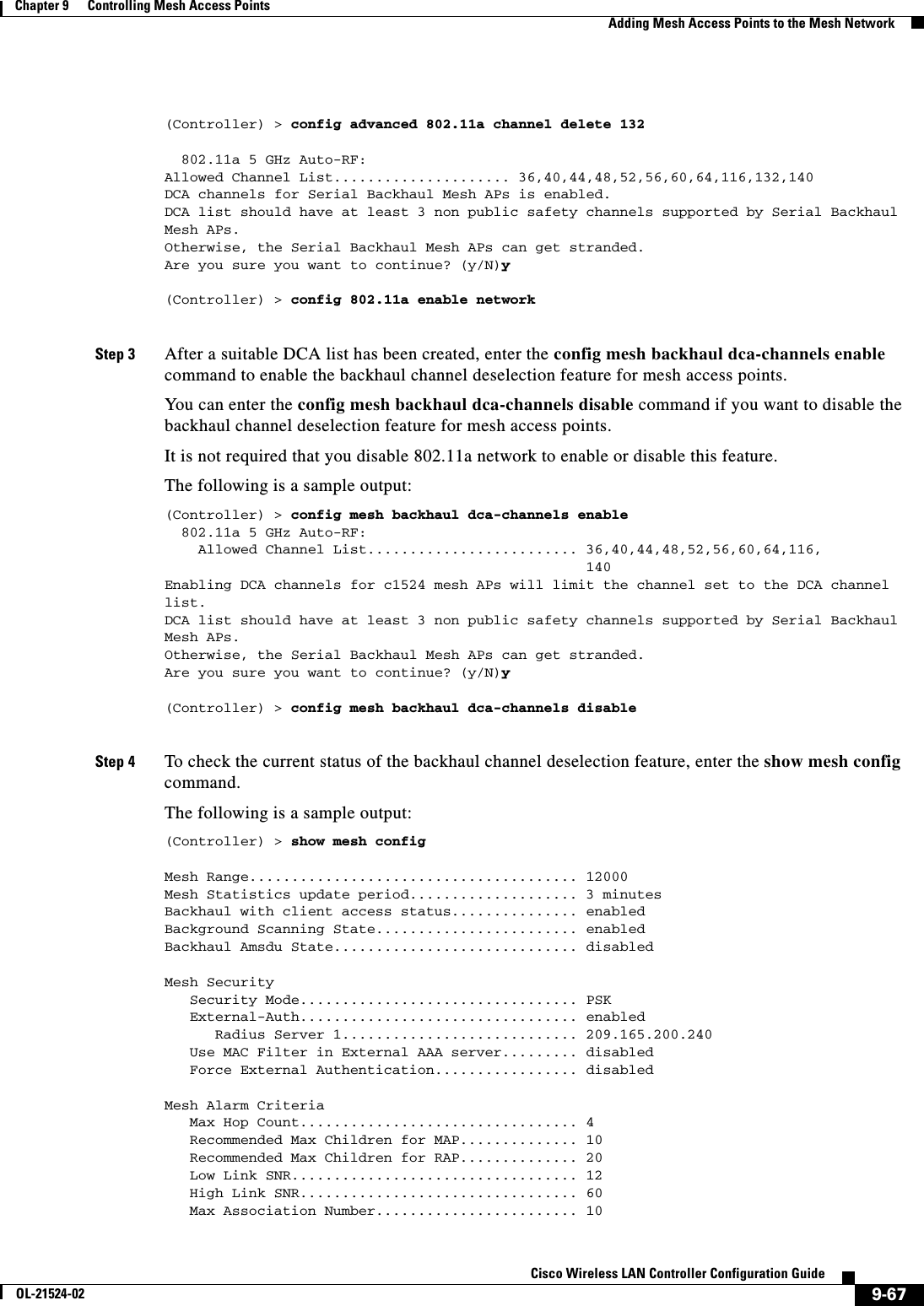
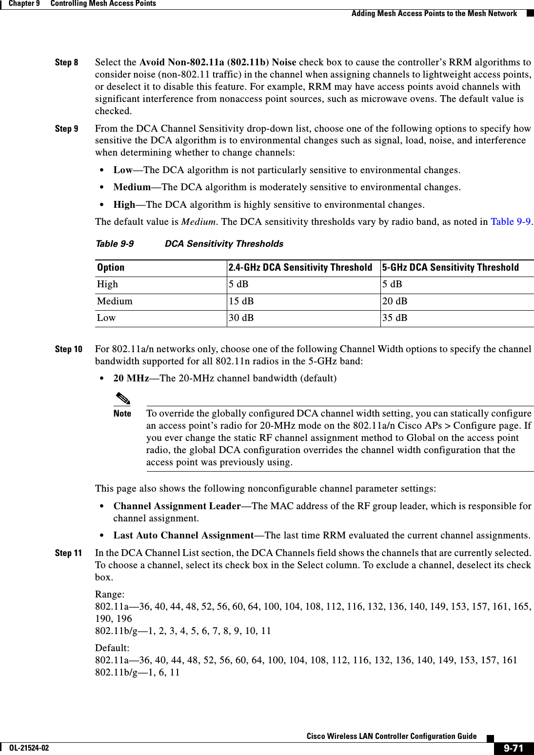
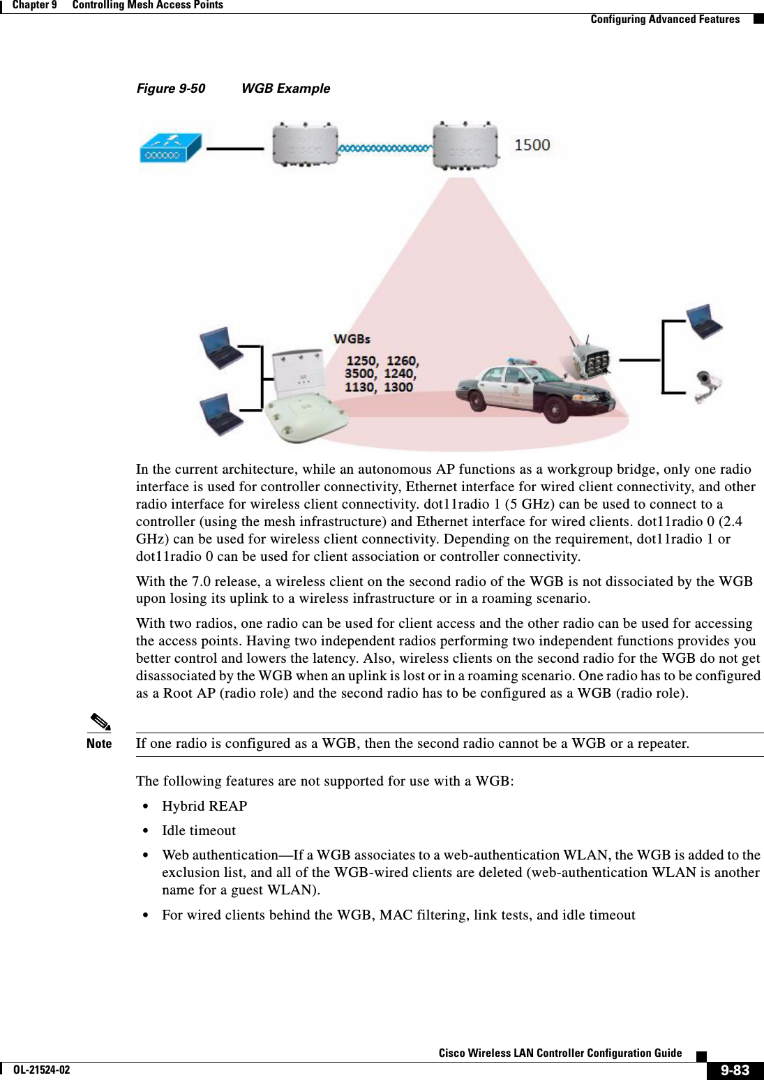
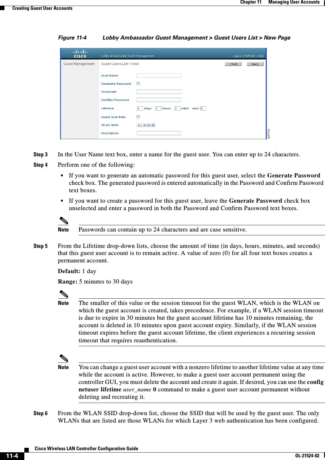
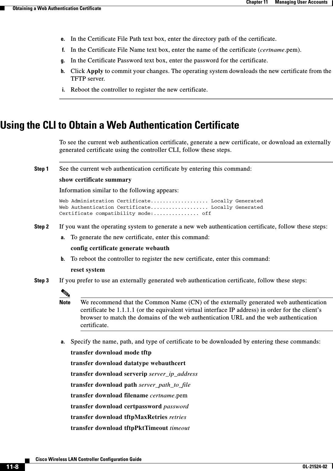
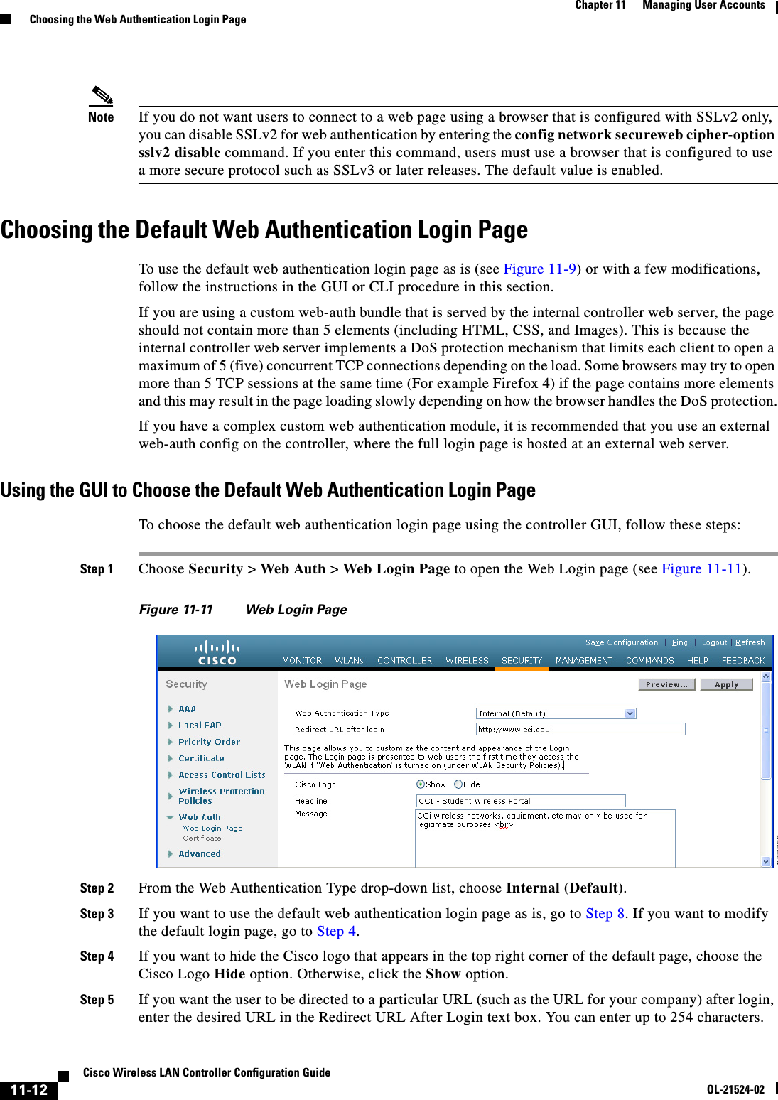
![10-14Cisco Wireless LAN Controller Configuration GuideOL-21524-02Chapter 10 Managing Controller Software and Configurations Upgrading the Controller Softwareconfig ap image swap {ap_name | all} • Display detailed information on access points specified for predownload by entering this command:show ap image {all | ap-name}Information similar to the following appears:Total number of APs.............................. 7Number of APs Initiated....................................... 4 Predownloading.................................. 0 Completed predownloading........................ 3 Not Supported................................... 0 Failed to Predownload........................... 0AP Name Primary Image Backup Image Predownload Predownload Version Next Retry Time Retry status Version Count------------------ -------------- -------------- --------------- -------------- ---------------- ------------AP1140-1 7.0.56.0 6.0.183.38 Complete 6.0.183.38 NA NAAP1140-2 7.0.56.0 6.0.183.58 Initiated 6.0.183.38 23:46:43 1AP1130-2 7.0.56.0 6.0.183.38 Complete 6.0.183.38 NA NAAP1130-3 7.0.56.0 6.0.183.58 Initiated 6.0.183.38 23:43:25 1AP1130-4 7.0.56.0 6.0.183.38 Complete 6.0.183.38 NA NAAP1130-5 7.0.56.0 6.0.183.58 Initiated 6.0.183.38 23:43:00 1AP1130-6 7.0.56.0 6.0.183.58 Initiated 6.0.183.38 23:41:33 1The output lists access points that are specified for predownloading and provides for each access point, primary and secondary image versions, the version of the predownload image, the predownload retry time (if necessary), and the number of predownload attempts. The output also includes the predownload status for each device. The status of the access points is as follows: • None—The access point is not scheduled for predownload. • Predownloading—The access point is predownloading the image. • Not supported—The access point (1120, 1230, and 1310) does not support predownloading. • Initiated—The access point is waiting to get the predownload image because the concurrent download limit has been reached. • Failed—The access point has failed 64 predownload attempts. • Complete—The access point has completed predownloading.Setting a Reboot TimeUse one of these commands to schedule a reboot of the controller and access points: • Specify the amount of time delay before the devices reboot by entering this command:reset system in HH:MM:SS image {swap | no-swap} reset-aps [save-config]Note The swap operand in the reset command will result in the swapping of the primary and backup images on both the controller and the access point.The controller sends a reset message to all joined access points, and then the controller resets. • Specify a date and time for the devices to reboot by entering this command:reset system at YYYY-MM-DD HH:MM:SS image {swap | no-swap} reset-aps [save-config]](https://usermanual.wiki/Cisco-Systems/102075.Cisco-Wireless-LAN-Controller-Configuration-Guide-6/User-Guide-1514966-Page-90.png)

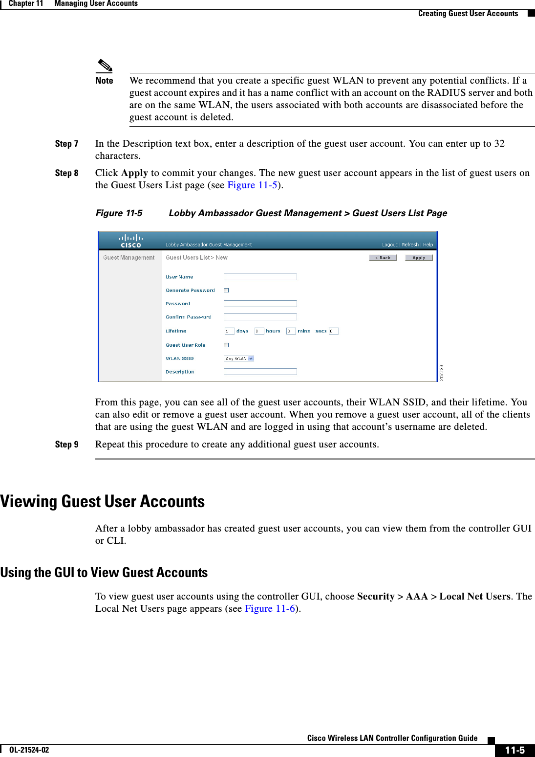
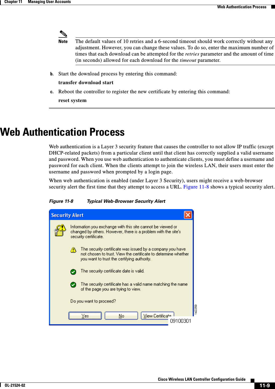
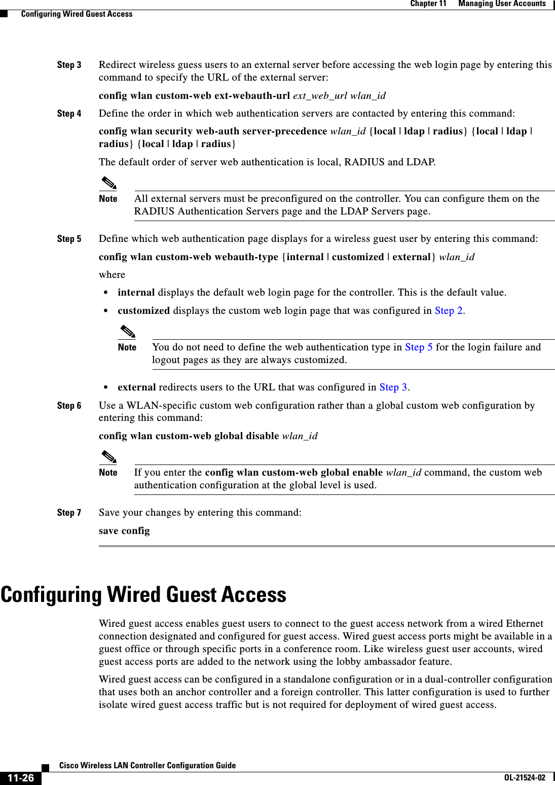
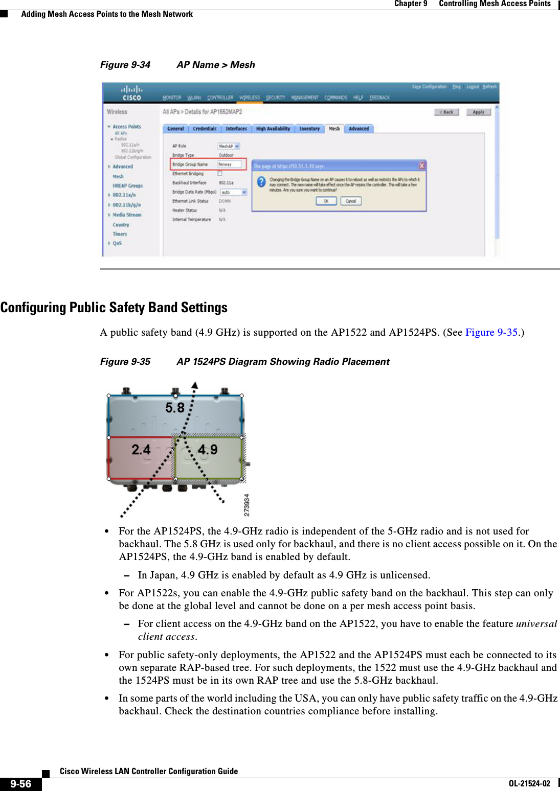
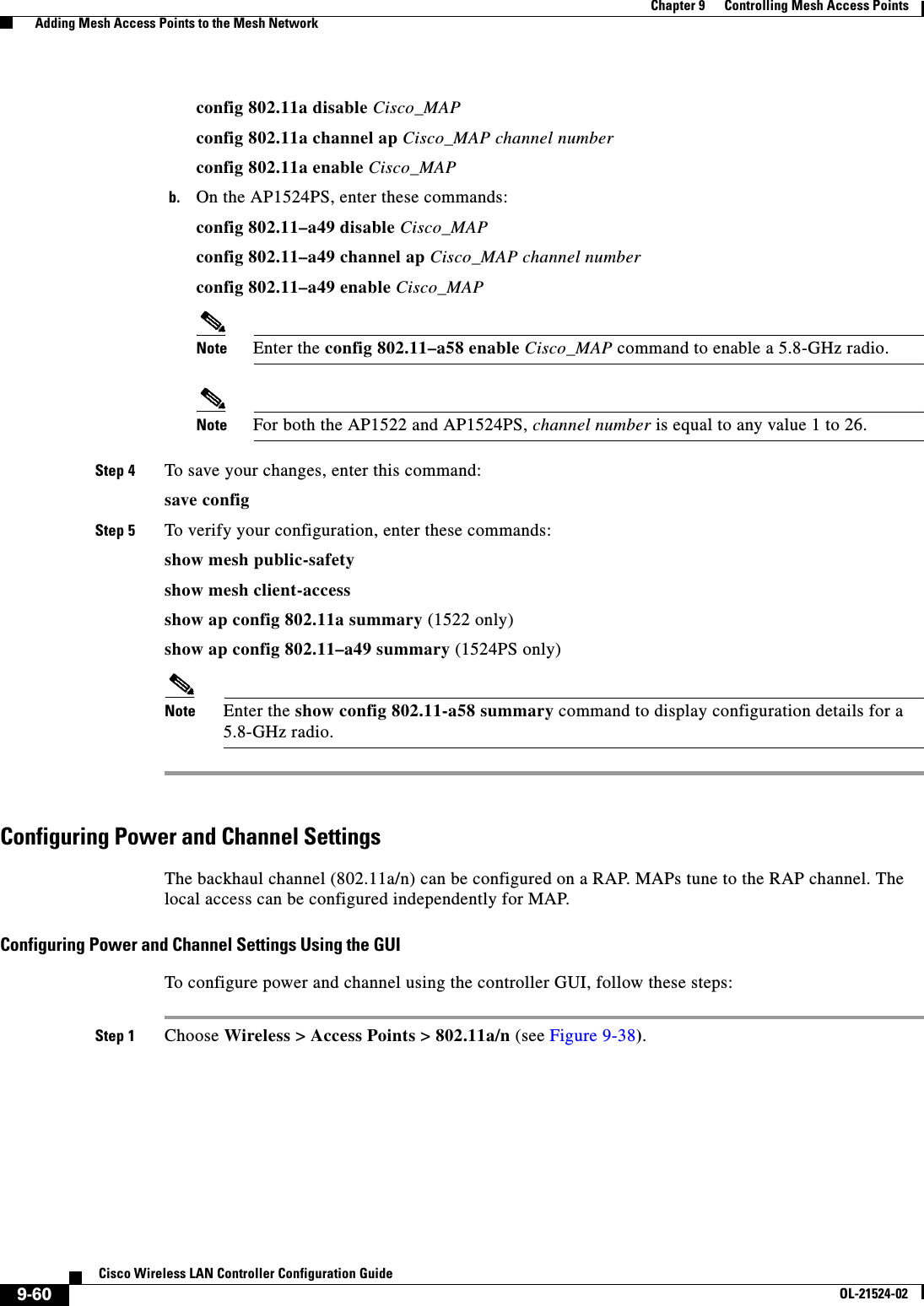
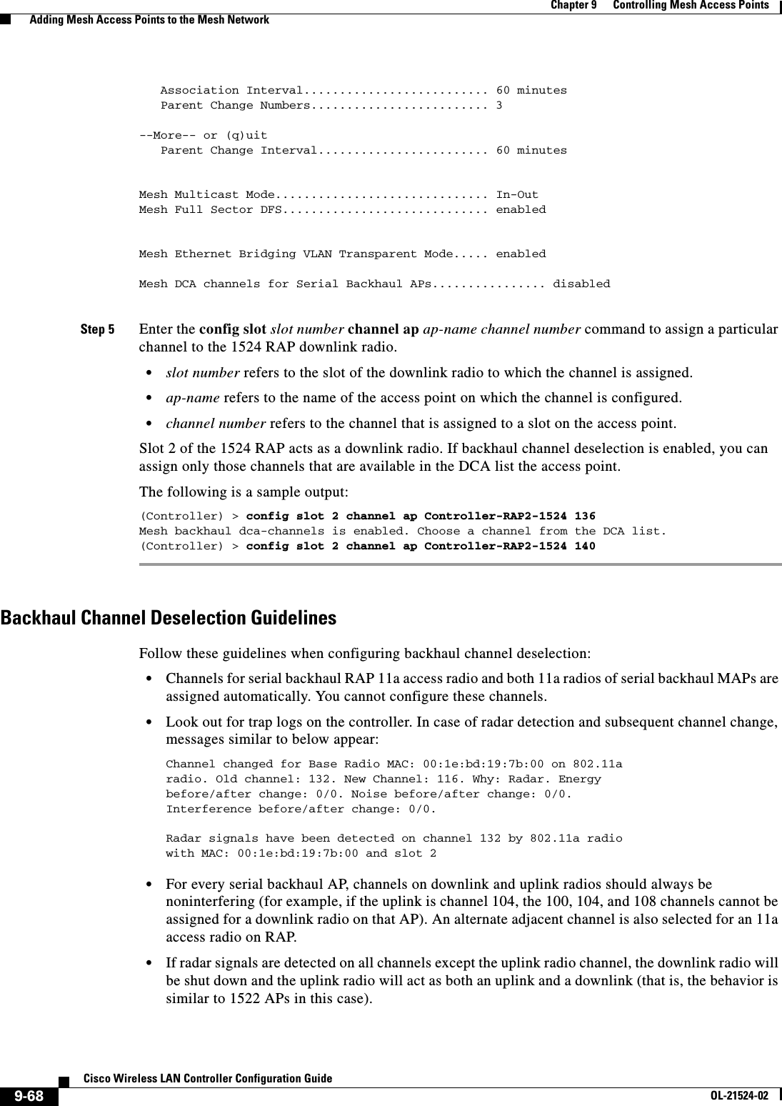
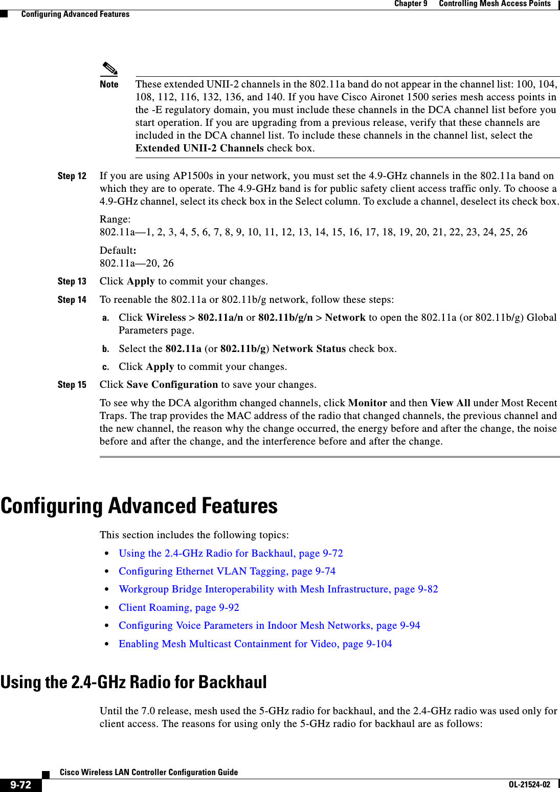
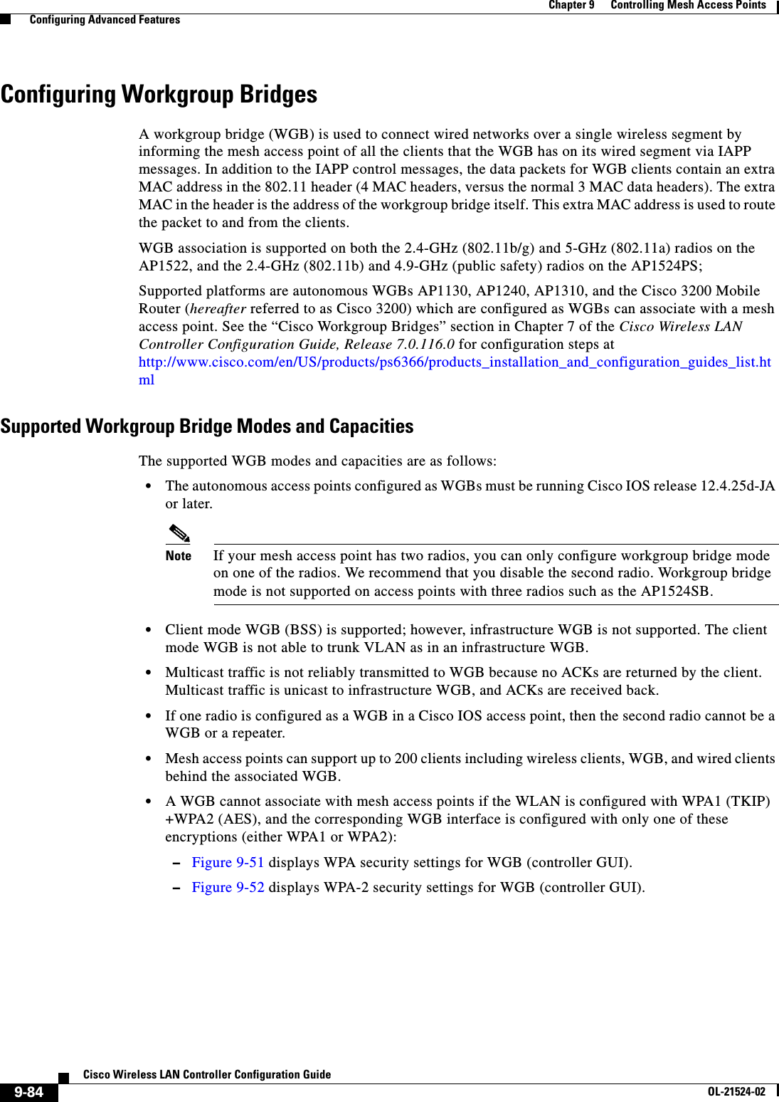
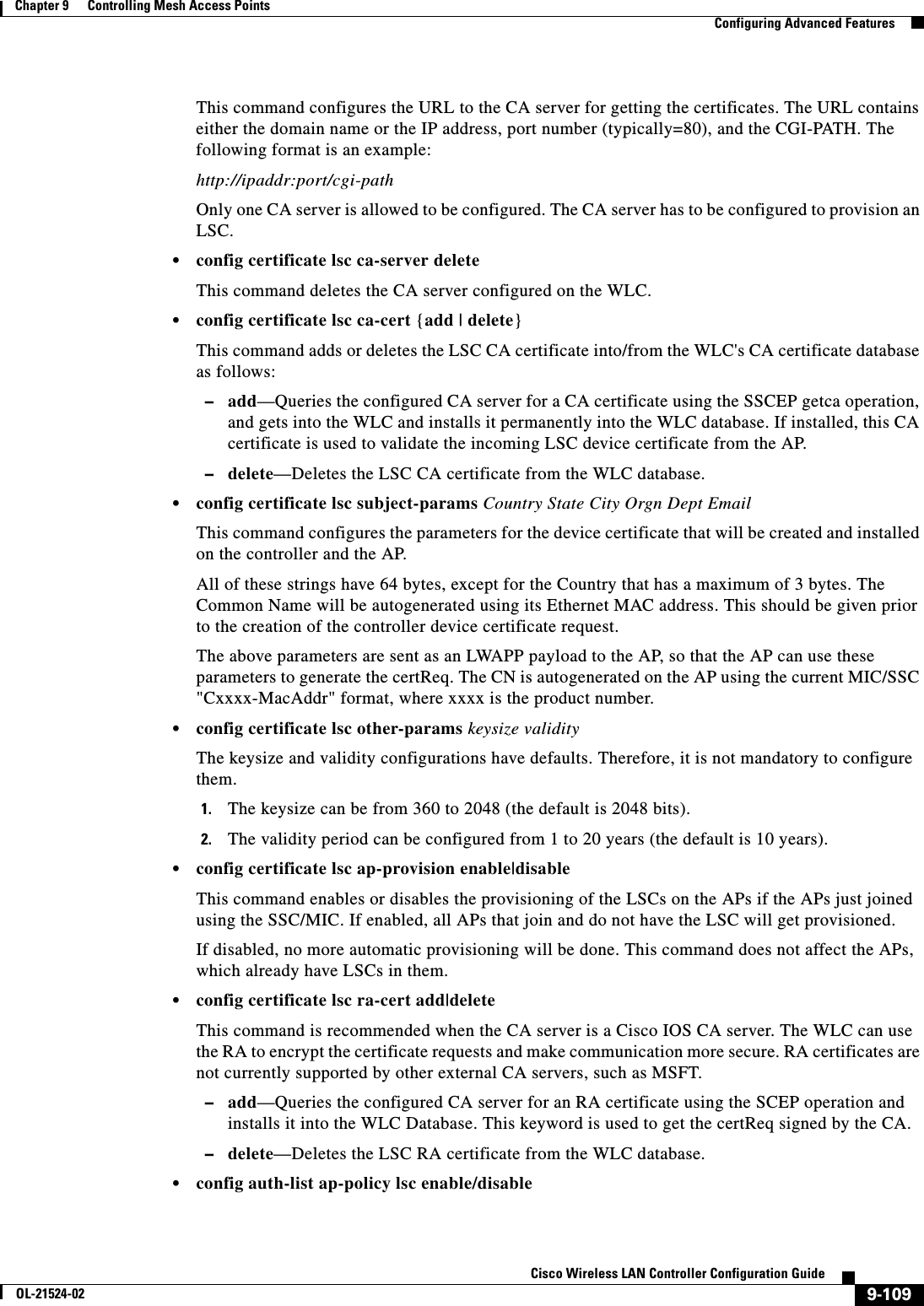
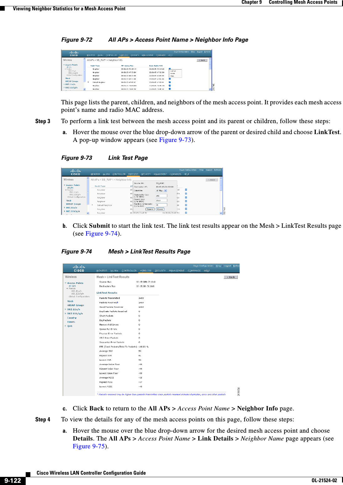
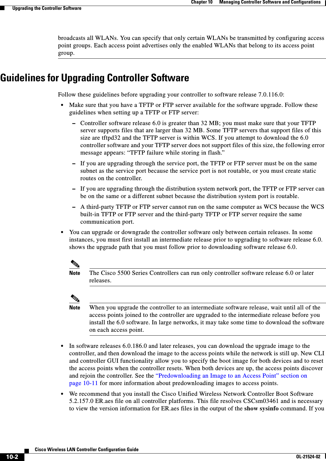
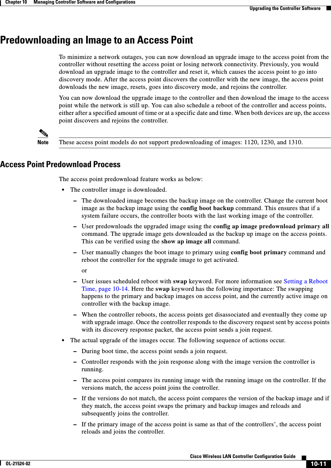
![11-16Cisco Wireless LAN Controller Configuration GuideOL-21524-02Chapter 11 Managing User Accounts Choosing the Web Authentication Login PageMode........................................... TFTP Data Type...................................... Login Image TFTP Server IP................................. xxx.xxx.xxx.xxx TFTP Path...................................... / TFTP Filename..................................... Logo.gifThis may take some time. Are you sure you want to start? (y/n) yTFTP Image transfer starting.Image installed.config custom-web redirecturl url • show custom-webCisco Logo.................. Disabled CustomLogo.................. 00_logo.gif Custom Title................ Welcome to the AcompanyBC Wireless LAN! Custom Message ............. Contact the System Administrator for a Username and Password. Custom Redirect URL......... http://www.AcompanyBC.com Web Authentication Mode..... Disabled Web Authentication URL........ DisabledCreating a Customized Web Authentication Login PageThis section provides information on creating a customized web authentication login page, which can then be accessed from an external web server.Here is a web authentication login page template. It can be used as a model when creating your own customized page:<html><head><meta http-equiv="Pragma" content="no-cache"><meta HTTP-EQUIV="Content-Type" CONTENT="text/html; charset=iso-8859-1"><title>Web Authentication</title><script>function submitAction(){var link = document.location.href;var searchString = "redirect=";var equalIndex = link.indexOf(searchString);var redirectUrl = "";if (document.forms[0].action == "") {var url = window.location.href;var args = new Object();var query = location.search.substring(1);var pairs = query.split("&");for(var i=0;i<pairs.length;i++){var pos = pairs[i].indexOf('=');if(pos == -1) continue;var argname = pairs[i].substring(0,pos);var value = pairs[i].substring(pos+1);args[argname] = unescape(value);}document.forms[0].action = args.switch_url; } if(equalIndex >= 0) {equalIndex += searchString.length;redirectUrl = "";redirectUrl += link.substring(equalIndex);](https://usermanual.wiki/Cisco-Systems/102075.Cisco-Wireless-LAN-Controller-Configuration-Guide-6/User-Guide-1514966-Page-128.png)
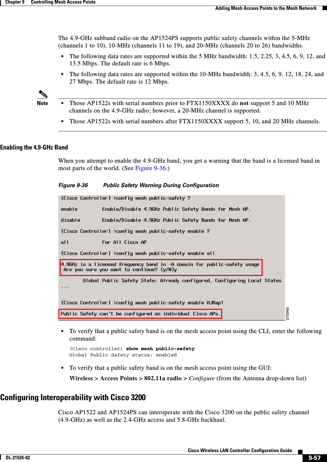
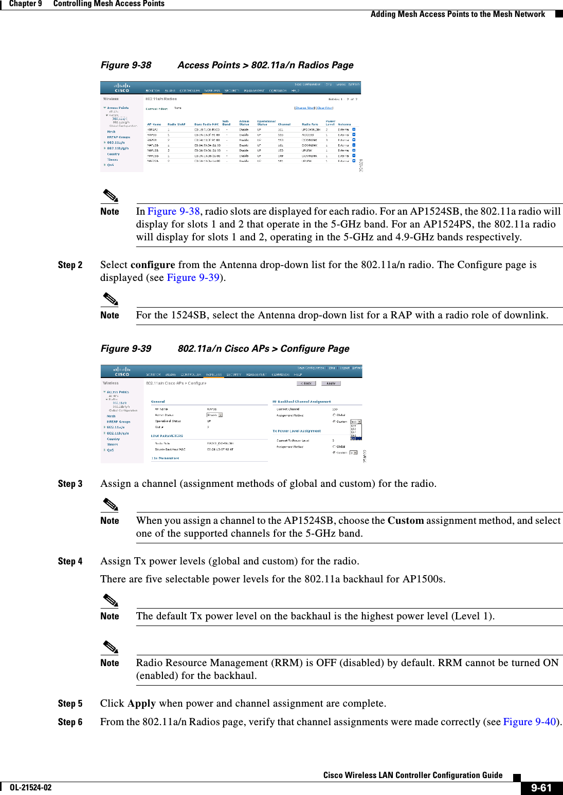
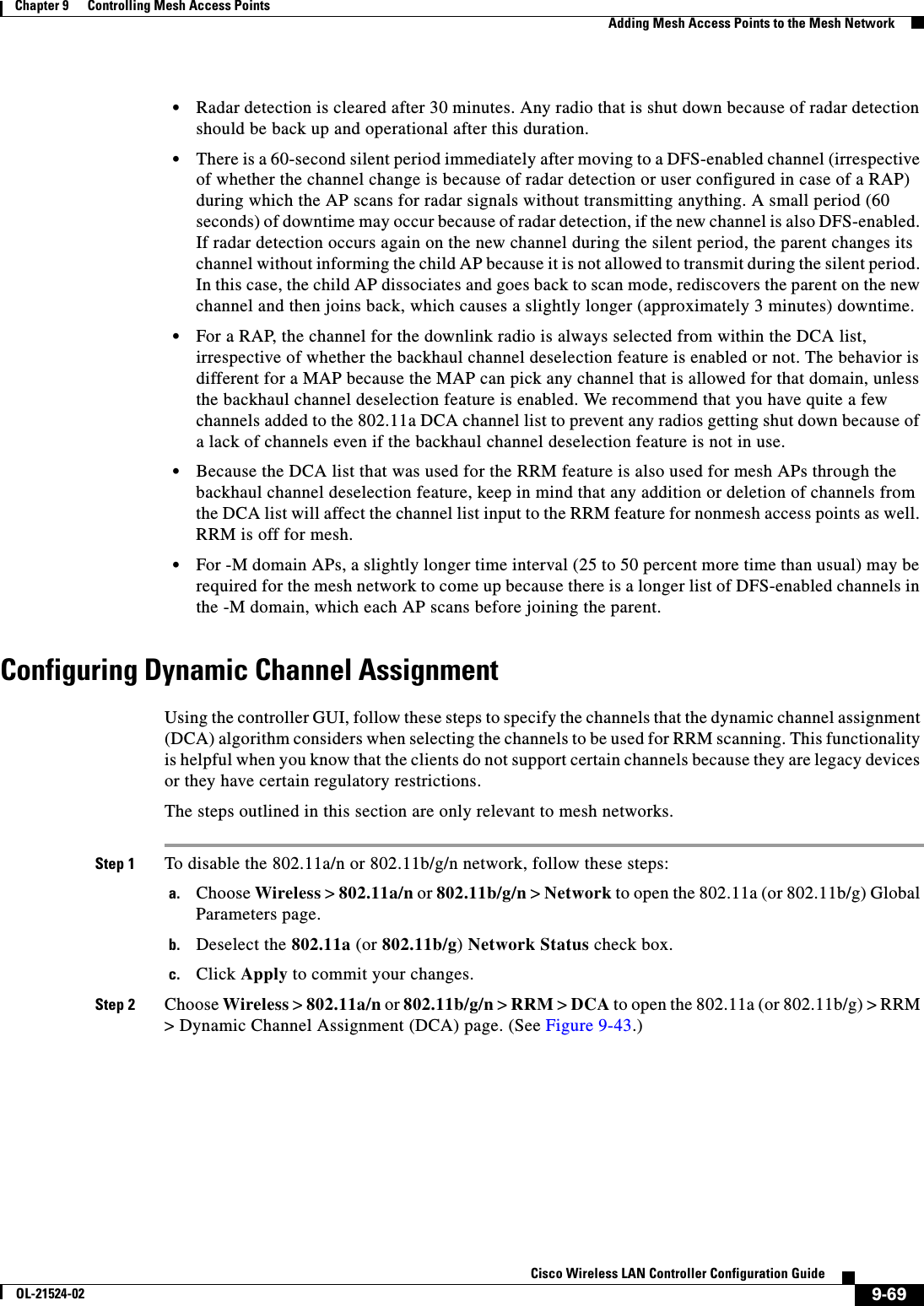
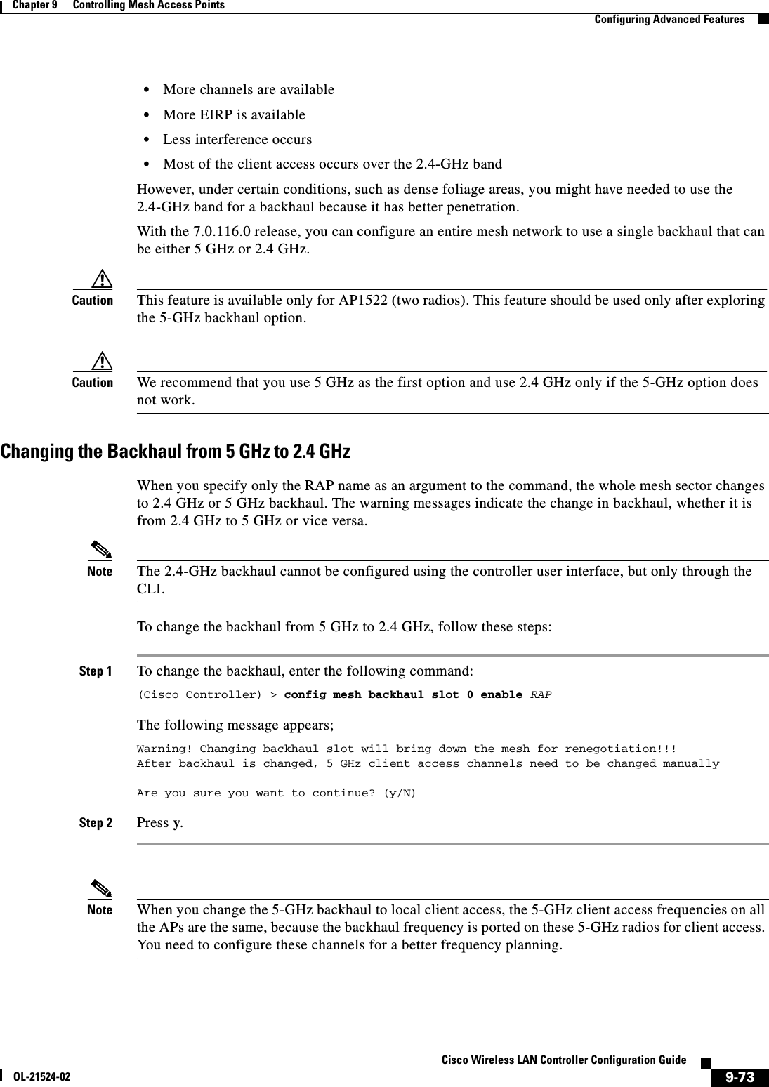
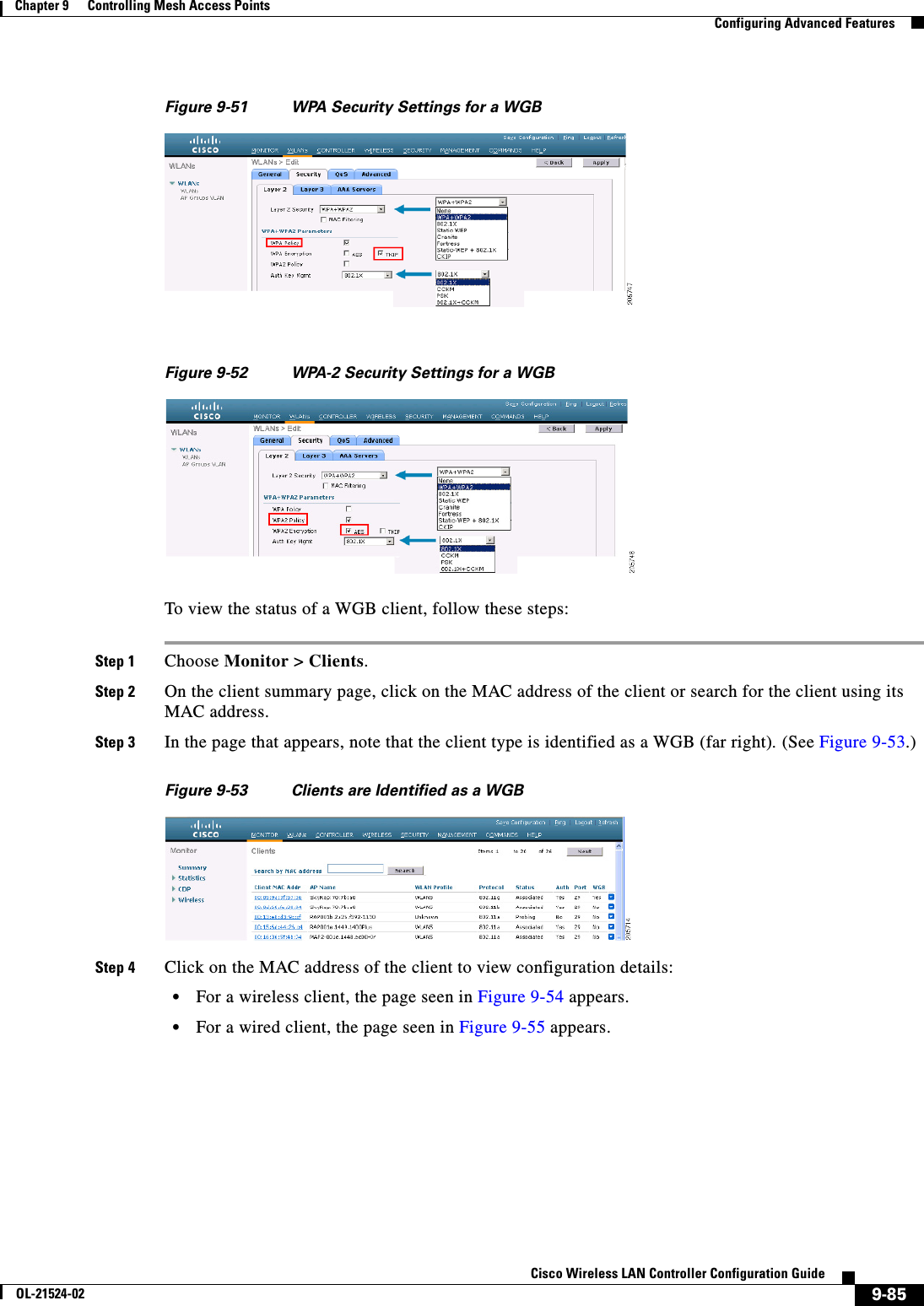
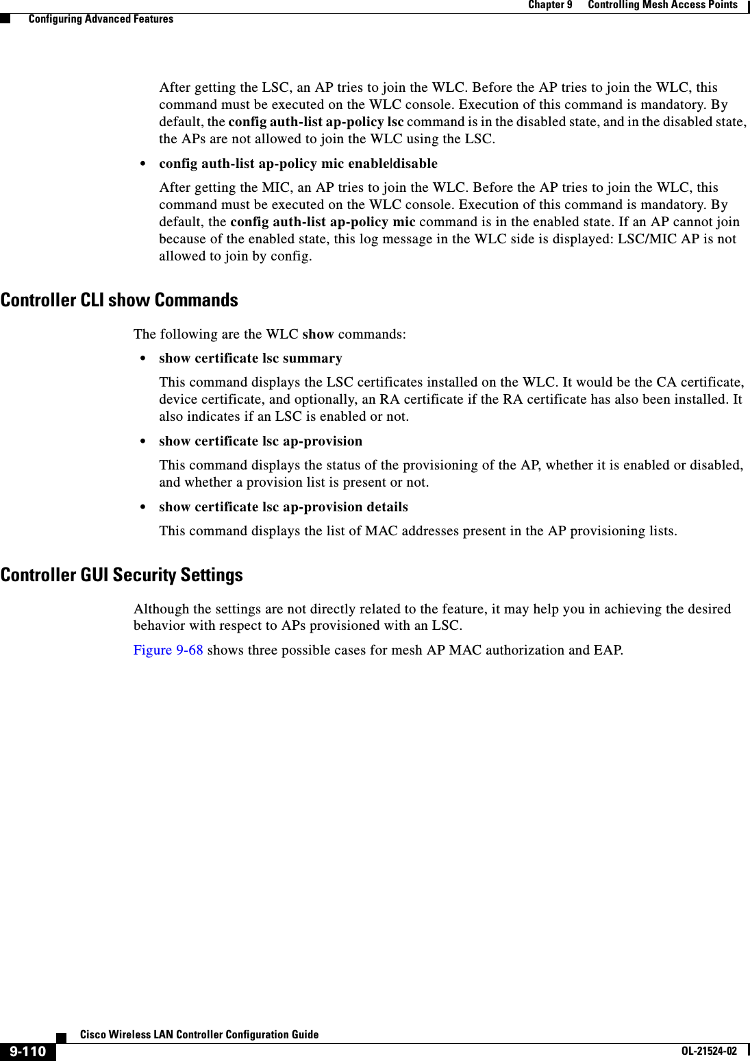
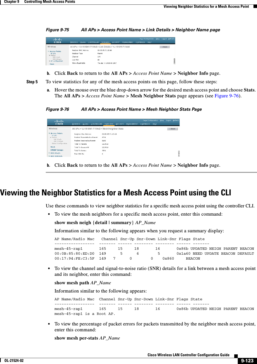
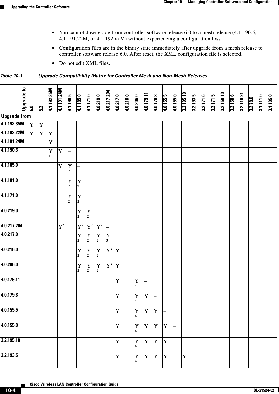
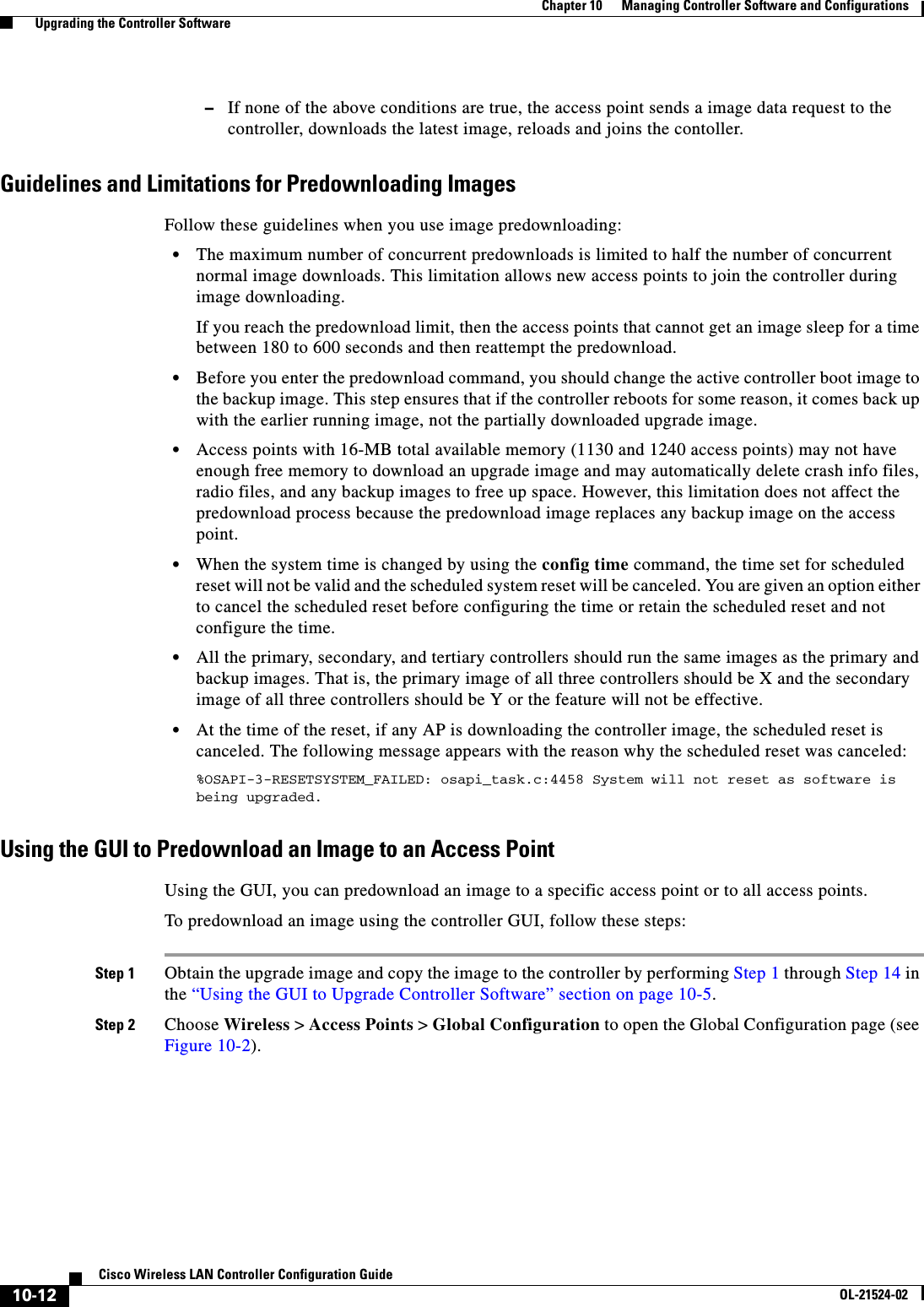
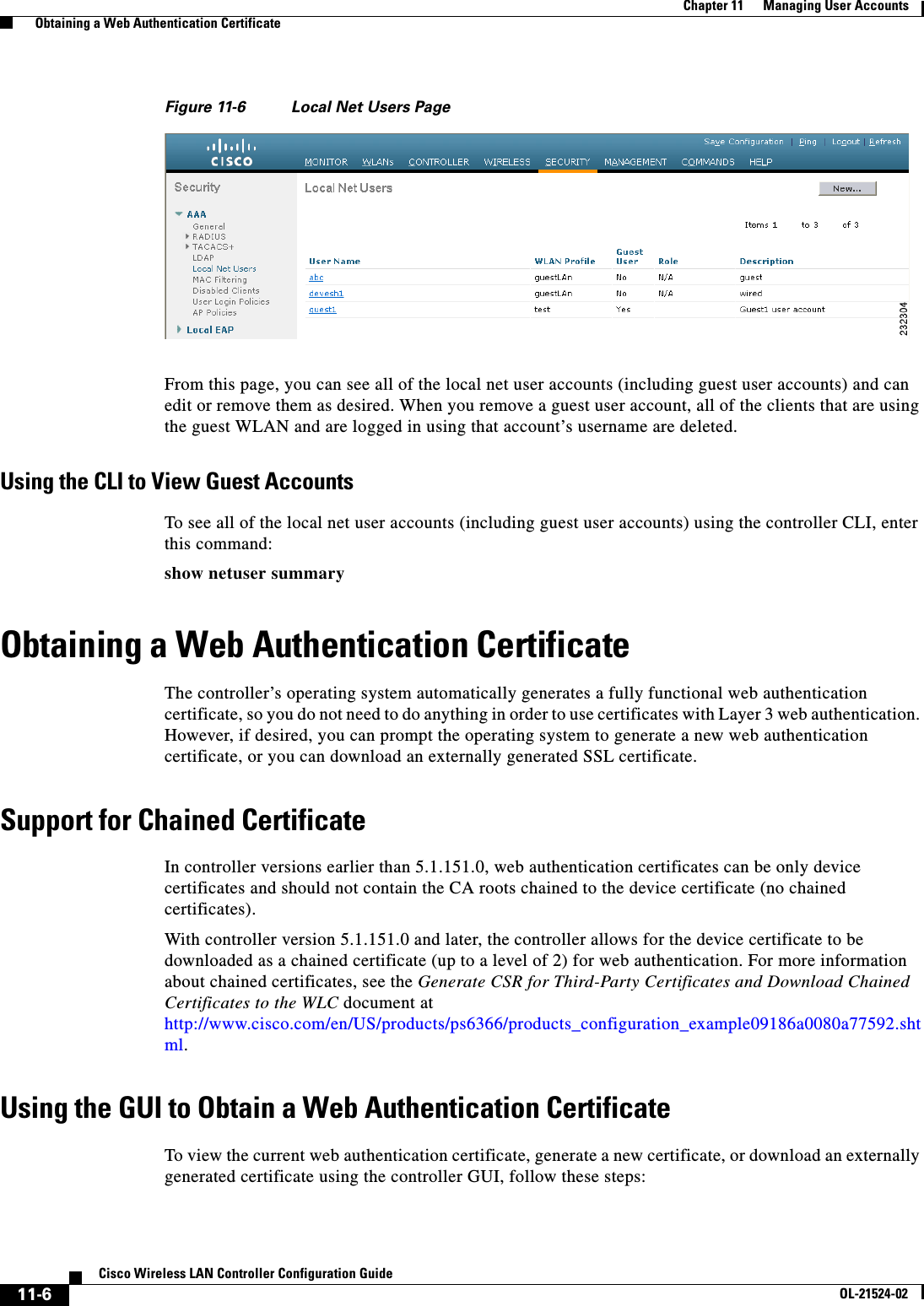
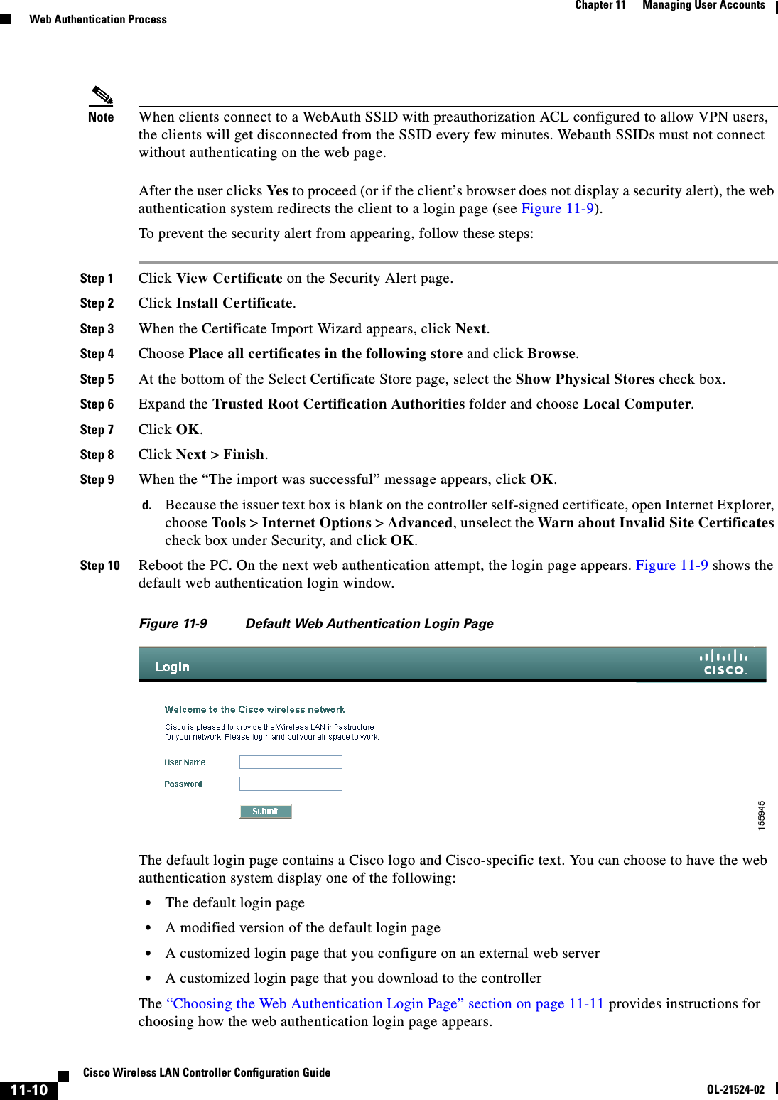
![11-17Cisco Wireless LAN Controller Configuration GuideOL-21524-02Chapter 11 Managing User Accounts Choosing the Web Authentication Login Page}if(redirectUrl.length > 255)redirectUrl = redirectUrl.substring(0,255);document.forms[0].redirect_url.value = redirectUrl;document.forms[0].buttonClicked.value = 4; document.forms[0].submit();}function loadAction(){ var url = window.location.href; var args = new Object(); var query = location.search.substring(1); var pairs = query.split("&"); for(var i=0;i<pairs.length;i++){ var pos = pairs[i].indexOf('='); if(pos == -1) continue; var argname = pairs[i].substring(0,pos); var value = pairs[i].substring(pos+1); args[argname] = unescape(value); }//alert( "AP MAC Address is " + args.ap_mac); //alert( "The Switch URL to post user credentials is " + args.switch_url); //document.forms[0].action = args.switch_url; // This is the status code returned from webauth login action // Any value of status code from 1 to 5 is error condition and user // should be shown error as below or modify the message as it suits // the customer if(args.statusCode == 1){ alert("You are already logged in. No further action is required on your part."); } else if(args.statusCode == 2){ alert("You are not configured to authenticate against web portal. No further action is required on your part."); } else if(args.statusCode == 3){ alert("The username specified cannot be used at this time. Perhaps the username is already logged into the system?"); } else if(args.statusCode == 4){ alert("The User has been excluded. Please contact the administrator."); } else if(args.statusCode == 5){ alert("Invalid username and password. Please try again."); }}</script></head><body topmargin="50" marginheight="50" onload="loadAction();"><form method="post" action="https://209.165.200.225/login.html"><input TYPE="hidden" NAME="buttonClicked" SIZE="16" MAXLENGTH="15" value="0"><input TYPE="hidden" NAME="redirect_url" SIZE="255" MAXLENGTH="255" VALUE=""><input TYPE="hidden" NAME="err_flag" SIZE="16" MAXLENGTH="15" value="0"><div align="center"><table border="0" cellspacing="0" cellpadding="0"><tr> <td>&nbsp;</td></tr><tr align="center"> <td colspan="2"><font size="10" color="#336699">Web Authentication</font></td></tr><tr align="center">](https://usermanual.wiki/Cisco-Systems/102075.Cisco-Wireless-LAN-Controller-Configuration-Guide-6/User-Guide-1514966-Page-129.png)