Cisco Systems 102075 Cisco Aironet 802.11n Dual Band Access Points User Manual Cisco Wireless LAN Controller Configuration Guide 7

Cisco Systems Inc Cisco Aironet 802.11n Dual Band Access Points Cisco Wireless LAN Controller Configuration Guide 7

Cisco Wireless LAN Controller Configuration Guide_7
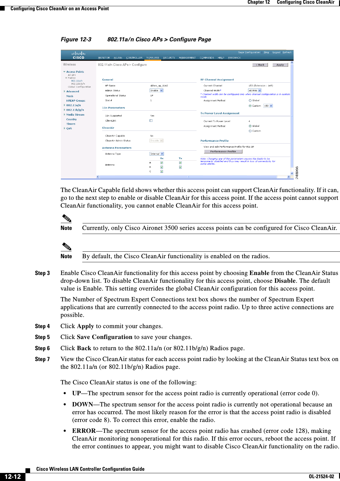
 11-27Cisco Wireless LAN Controller Configuration GuideOL-21524-02Chapter 11      Managing User Accounts  Configuring Wired Guest AccessWired guest access ports initially terminate on a Layer 2 access switch or switch port configured with VLAN interfaces for wired guest access traffic. The wired guest traffic is then trunked from the access switch to a controller. This controller is configured with an interface that is mapped to a wired guest access VLAN on the access switch. See Figure 11-16.Figure 11-16 Wired Guest Access Example with One ControllerIf two controllers are being used, the foreign controller, which receives the wired guest traffic from the access switch, forwards it to the anchor controller. A bidirectional EoIP tunnel is established between the foreign and anchor controllers to handle this traffic. See Figure 11-17.232048InternetVLAN ID: 236,guest LAN: 1egress interface,guest-dsingress interface,sidkrish-intfController(foreign)Controller(anchor)SSID: internalSSID: guestWirelessguestclientAccessswitchConferenceroomGuestofficeWired guest access portsWired guest access ports
 11-28Cisco Wireless LAN Controller Configuration GuideOL-21524-02Chapter 11      Managing User Accounts  Configuring Wired Guest AccessFigure 11-17 Wired Guest Access Example with Two ControllersNote Although wired guest access is managed by anchor and foreign anchors when two controllers are deployed, mobility is not supported for wired guest access clients. In this case, DHCP and web authentication for the client are handled by the anchor controller.Note You can specify the amount of bandwidth allocated to a wired guest user in the network by configuring a QoS role and a bandwidth contract. For details on configuring these features. See the “Configuring Quality of Service” section on page 4-68.Configuration OverviewTo configure wired guest access on a wireless network, you will perform the following:1. Configure a dynamic interface (VLAN) for wired guest user access2. Create a wired LAN for guest user access3. Configure the controller4. Configure the anchor controller (if terminating traffic on another controller)5. Configure security for the guest LAN6. Verify the configurationWired Guest Access GuidelinesFollow these guidelines before using wired guest access on your network:  • Wired guest access is supported only on the following controllers: 5500 and 4400 series controllers, the Cisco WiSM, and the Catalyst 3750G Integrated Wireless LAN Controller Switch.   • Wired guest access interfaces must be tagged.232347InternetSSID: InternalSSID: GUESTWiredguestclientAccessswitchWirelessguest clientWired guest portsWired guest portsWired guest portsAnchor controller,mobility anchor,export-anchorForeign controller,export-foreign
 11-29Cisco Wireless LAN Controller Configuration GuideOL-21524-02Chapter 11      Managing User Accounts  Configuring Wired Guest Access  • Wired guest access ports must be in the same Layer 2 network as the foreign controller.  • Up to five wired guest access LANs can be configured on a controller.  • Layer 3 web authentication and web passthrough are supported for wired guest access clients. Layer 2 security is not supported.  • Do not attempt to trunk a guest VLAN on the Catalyst 3750G Integrated Wireless LAN Controller Switch to multiple controllers. Redundancy cannot be achieved by doing this action.Using the GUI to Configure Wired Guest AccessTo configure wired guest user access on your network using the controller GUI, follow these steps:Step 1 To create a dynamic interface for wired guest user access, choose Controller > Interfaces. The Interfaces page appears.Step 2 Click New to open the Interfaces > New page.Step 3 Enter a name and VLAN ID for the new interface.Step 4 Click Apply to commit your changes.Step 5 In the Port Number text box, enter a valid port number. You can enter a number between 0 and 25 (inclusive).Step 6 Select the Guest LAN check box.Step 7 Click Apply to commit your changes.Step 8 To create a wired LAN for guest user access, choose WLANs.Step 9 On the WLANs page, choose Create New from the drop-down list and click Go. The WLANs > New page appears (see Figure 11-18).Figure 11-18 WLANs > New PageStep 10 From the Type drop-down list, choose Guest LAN.Step 11 In the Profile Name text box, enter a name that identifies the guest LAN. Do not use any spaces.Step 12 From the WLAN ID drop-down list, choose the ID number for this guest LAN.Note You can create up to five guest LANs, so the WLAN ID options are 1 through 5 (inclusive).Step 13 Click Apply to commit your changes. The WLANs > Edit page appears (see Figure 11-19).
 11-30Cisco Wireless LAN Controller Configuration GuideOL-21524-02Chapter 11      Managing User Accounts  Configuring Wired Guest AccessFigure 11-19 WLANs > Edit PageStep 14 Select the Enabled check box for the Status parameter.Step 15 Web authentication (Web-Auth) is the default security policy. If you want to change this to web passthrough, choose the Security tab after completing Step 16 and Step 17.Step 16 From the Ingress Interface drop-down list, choose the VLAN that you created in Step 3. This VLAN provides a path between the wired guest client and the controller by way of the Layer 2 access switch.Step 17 From the Egress Interface drop-down list, choose the name of the interface. This WLAN provides a path out of the controller for wired guest client traffic.Step 18 If you want to change the authentication method (for example, from web authentication to web passthrough), choose Security > Layer 3. The WLANs > Edit (Security > Layer 3) page appears (see Figure 11-20).Figure 11-20 WLANs > Edit (Security > Layer 3) PageStep 19 From the Layer 3 Security drop-down list, choose one of the following:  • None—Layer 3 security is disabled.  • Web Authentication—Causes users to be prompted for a username and password when connecting to the wireless network. This is the default value.  • Web Passthrough—Allows users to access the network without entering a username and password.Note There should not be a Layer 3 gateway on the guest wired VLAN, as this would bypass the web authentication done through the controller.
 11-31Cisco Wireless LAN Controller Configuration GuideOL-21524-02Chapter 11      Managing User Accounts  Configuring Wired Guest AccessStep 20 If you choose the Web Passthrough option, an Email Input check box appears. Select this check box if you want users to be prompted for their e-mail address when attempting to connect to the network.Step 21 To override the global authentication configuration set on the Web Login page, select the Override Global Config check box.Step 22 When the Web Auth Type drop-down list appears, choose one of the following options to define the web authentication pages for wired guest users:  • Internal—Displays the default web login page for the controller. This is the default value.  • Customized—Displays custom web login, login failure, and logout pages. If you choose this option, three separate drop-down lists appear for login, login failure, and logout page selection. You do not need to define a customized page for all three options. Choose None from the appropriate drop-down list if you do not want to display a customized page for that option.Note These optional login, login failure, and logout pages are downloaded to the controller as webauth.tar files.  • External—Redirects users to an external server for authentication. If you choose this option, you must also enter the URL of the external server in the URL text box.You can choose specific RADIUS or LDAP servers to provide external authentication on the WLANs > Edit (Security > AAA Servers) page. Additionally, you can define the priority in which the servers provide authentication.Step 23 If you chose External as the web authentication type in Step 22, choose AAA Servers and choose up to three RADIUS and LDAP servers using the drop-down lists.Note The RADIUS and LDAP external servers must already be configured in order to be selectable options on the WLANs > Edit (Security > AAA Servers) page. You can configure these servers on the RADIUS Authentication Servers page and LDAP Servers page.Step 24 To establish the priority in which the servers are contacted to perform web authentication as follows:Note The default order is local, RADIUS, LDAP.a. Highlight the server type (local, RADIUS, or LDAP) that you want to be contacted first in the box next to the Up and Down buttons.b. Click Up and Down until the desired server type is at the top of the box.c. Click the < arrow to move the server type to the priority box on the left.d. Repeat these steps to assign priority to the other servers.Step 25 Click Apply to commit your changes.Step 26 Click Save Configuration to save your changes.Step 27 Repeat this process if a second (anchor) controller is being used in the network.
 11-32Cisco Wireless LAN Controller Configuration GuideOL-21524-02Chapter 11      Managing User Accounts  Configuring Wired Guest AccessUsing the CLI to Configure Wired Guest AccessTo configure wired guest user access on your network using the controller CLI, follow these steps:Step 1 Create a dynamic interface (VLAN) for wired guest user access by entering this command:config interface create interface_name vlan_idStep 2 If link aggregation trunk is not configured, enter this command to map a physical port to the interface:config interface port interface_name primary_port {secondary_port}Step 3 Enable or disable the guest LAN VLAN by entering this command:config interface guest-lan interface_name {enable | disable}This VLAN is later associated with the ingress interface created in Step 5.Step 4 Create a wired LAN for wired client traffic and associate it to an interface by entering this command:config guest-lan create guest_lan_id interface_nameThe guest LAN ID must be a value between 1 and 5 (inclusive).Note To delete a wired guest LAN, enter the config guest-lan delete guest_lan_id command.Step 5 Configure the wired guest VLAN’s ingress interface, which provides a path between the wired guest client and the controller by way of the Layer 2 access switch by entering this command:config guest-lan ingress-interface guest_lan_id interface_nameStep 6 Configure an egress interface to transmit wired guest traffic out of the controller by entering this command:config guest-lan interface guest_lan_id interface_nameNote If the wired guest traffic is terminating on another controller, repeat Step 4 and Step 6 for the terminating (anchor) controller and Step 1 through Step 5 for the originating (foreign) controller. Additionally, configure the config mobility group anchor add {guest-lan guest_lan_id | wlan wlan_id} IP_address command for both controllers.Step 7 Configure the security policy for the wired guest LAN by entering this command:config guest-lan security {web-auth enable guest_lan_id | web-passthrough enable guest_lan_id}Note Web authentication is the default setting.Step 8 Enable or disable a wired guest LAN by entering this command:config guest-lan {enable | disable} guest_lan_idStep 9 If you want wired guest users to log into a customized web login, login failure, or logout page, enter these commands to specify the filename of the web authentication page and the guest LAN for which it should display:  • config guest-lan custom-web login-page page_name guest_lan_id—Defines a web login page.  • config guest-lan custom-web loginfailure-page page_name guest_lan_id—Defines a web login failure page.
 11-33Cisco Wireless LAN Controller Configuration GuideOL-21524-02Chapter 11      Managing User Accounts  Configuring Wired Guest AccessNote To use the controller’s default login failure page, enter the config guest-lan custom-web loginfailure-page none guest_lan_id command.  • config guest-lan custom-web logout-page page_name guest_lan_id—Defines a web logout page.Note To use the controller’s default logout page, enter the config guest-lan custom-web logout-page none guest_lan_id command.Step 10 If you want wired guest users to be redirected to an external server before accessing the web login page, enter this command to specify the URL of the external server:config guest-lan custom-web ext-webauth-url ext_web_url guest_lan_idStep 11 If you want to define the order in which local (controller) or external (RADIUS, LDAP) web authentication servers are contacted, enter this command:config wlan security web-auth server-precedence wlan_id {local | ldap | radius} {local | ldap | radius} {local | ldap | radius}The default order of server web authentication is local, RADIUS, LDAP.Note All external servers must be preconfigured on the controller. You can configure them on the RADIUS Authentication Servers page or the LDAP Servers page.Step 12 Define the web login page for wired guest users by entering this command:config guest-lan custom-web webauth-type {internal | customized | external} guest_lan_idwhere  • internal displays the default web login page for the controller. This is the default value.  • customized displays the custom web pages (login, login failure, or logout) that were configured in Step 9.  • external redirects users to the URL that was configured in Step 10.Step 13 Use a guest-LAN specific custom web configuration rather than a global custom web configuration by entering this command:config guest-lan custom-web global disable guest_lan_idNote If you enter the config guest-lan custom-web global enable guest_lan_id command, the custom web authentication configuration at the global level is used.Step 14 Save your changes by entering this command:save configNote Information on the configured web authentication appears in both the show run-config and show running-config commands.Step 15 Display the customized web authentication settings for a specific guest LAN by entering this command:show custom-web {all | guest-lan guest_lan_id}
 11-34Cisco Wireless LAN Controller Configuration GuideOL-21524-02Chapter 11      Managing User Accounts  Configuring Wired Guest AccessNote If internal web authentication is configured, the Web Authentication Type displays as internal rather than external (controller level) or customized (WLAN profile level).Information similar to the following appears for the show custom-web all command:Radius Authentication Method..................... PAPCisco Logo....................................... Enabled CustomLogo....................................... NoneCustom Title..................................... NoneCustom Message................................... NoneCustom Redirect URL.............................. NoneWeb Authentication Type...............            ExternalExternal Web Authentication URL............       http:\\9.43.0.100\login.htmlExternal Web Server listIndex IP Address----- ---------------1   9.43.0.1002 0.0.0.03 0.0.0.04 0.0.0.05 0.0.0.0...       20 0.0.0.0Configuration Per Profile:WLAN ID: 1WLAN Status................................... EnabledWeb Security Policy........................... Web Based AuthenticationGlobal Status................................. DisabledWebAuth Type.................................. CustomizedLogin Page.................................... login1.htmlLoginfailure page name....................... loginfailure1.htmlLogout page name............................. logout1.htmlWLAN ID: 2WLAN Status................................... EnabledWeb Security Policy........................... Web Based AuthenticationGlobal Status................................. DisabledWebAuth Type.................................. InternalLoginfailure page name........................ NoneLogout page name.............................. NoneWLAN ID: 3WLAN Status................................... EnabledWeb Security Policy........................... Web Based AuthenticationGlobal Status................................. DisabledWebAuth Type.................................. CustomizedLogin Page.................................... login.htmlLoginfailure page name........................ LF2.htmlLogout page name.............................. LG2.htmlInformation similar to the following appears for the show custom-web guest-lan guest_lan_id command:Guest LAN ID: 1Guest LAN Status.............................. DisabledWeb Security Policy........................... Web Based AuthenticationGlobal Status................................. EnabledWebAuth Type.................................. Internal
 11-35Cisco Wireless LAN Controller Configuration GuideOL-21524-02Chapter 11      Managing User Accounts  Configuring Wired Guest AccessLoginfailure page name........................ NoneLogout page name.............................. NoneStep 16 Display a summary of the local interfaces by entering this command:show interface summaryInformation similar to the following appears:Interface Name                   Port Vlan Id  IP Address      Type    Ap Mgr Guest   -------------------------------- ---- -------- --------------- ------- ------ ----- ap-manager                       1    untagged 1.100.163.25    Static  Yes    Nomanagement                       1    untagged 1.100.163.24    Static  No     Noservice-port                     N/A  N/A      172.19.35.31    Static  No     Novirtual                          N/A  N/A      1.1.1.1         Static  No     Nowired                            1    20       10.20.20.8      Dynamic No     Nowired-guest                      1  236     10.20.236.50   Dynamic No    Yes Note The interface name of the wired guest LAN in this example is wired-guest and its VLAN ID is 236.Display detailed interface information by entering this command:show interface detailed interface_nameInformation similar to the following appears:Interface Name................................... wired-guestMAC Address...................................... 00:1a:6d:dd:1e:40IP Address....................................... 0.0.0.0DHCP Option 82................................... DisabledVirtual DNS Host Name............................ DisabledAP Manager....................................... NoGuest Interface.................................. No Step 17 Display the configuration of a specific wired guest LAN by entering this command:show guest-lan guest_lan_idInformation similar to the following appears:Guest LAN Identifier............................. 1Profile Name..................................... guestlanNetwork Name (SSID).............................. guestlanStatus........................................... EnabledAAA Policy Override.............................. DisabledNumber of Active Clients......................... 1Exclusionlist Timeout............................ 60 secondsSession Timeout.................................. InfinityInterface........................................ wiredIngress Interface................................ wired-guestWLAN ACL......................................... unconfiguredDHCP Server...................................... 10.20.236.90DHCP Address Assignment Required................. DisabledQuality of Service............................... Silver (best effort)SecurityWeb Based Authentication...................... EnabledACL........................................... UnconfiguredWeb-Passthrough............................... DisabledConditional Web Redirect...................... Disabled
 11-36Cisco Wireless LAN Controller Configuration GuideOL-21524-02Chapter 11      Managing User Accounts  Configuring Wired Guest AccessAuto Anchor................................... DisabledMobility Anchor ListGLAN ID IP Address Status------- --------------- ------Note Enter the show guest-lan summary command to see all wired guest LANs configured on the controller.Step 18 Display the active wired guest LAN clients by entering this command:show client summary guest-lanInformation similar to the following appears:Number of Clients................................ 1MAC Address     AP Name Status     WLAN  Auth  Protocol  Port Wired------------------- ------- ----------- ----- ----- --------- ----- ------00:16:36:40:ac:58   N/A   Associated   1    No   802.3    1   Yes Step 19 Display detailed information for a specific client by entering this command:show client detail client_macInformation similar to the following appears:Client MAC Address............................... 00:40:96:b2:a3:44Client Username ................................. N/AAP MAC Address................................... 00:18:74:c7:c0:90Client State..................................... AssociatedWireless LAN Id.................................. 1BSSID............................................ 00:18:74:c7:c0:9fChannel.......................................... 56IP Address....................................... 192.168.10.28Association Id................................... 1Authentication Algorithm......................... Open SystemReason Code...................................... 0Status Code...................................... 0Session Timeout.................................. 0Client CCX version............................... 5Client E2E version............................... No E2E supportDiagnostics Capability........................... SupportedS69 Capability................................... SupportedMirroring........................................ DisabledQoS Level........................................ Silver...
CHAPTER12-1Cisco Wireless LAN Controller Configuration GuideOL-21524-0212Configuring Cisco CleanAirThis chapter describes how to configure Cisco CleanAir functionality on the controller and lightweight access points. It contains these sections:  • Overview of Cisco CleanAir, page 12-1  • Configuring Cisco CleanAir on the Controller, page 12-5  • Configuring Cisco CleanAir on an Access Point, page 12-11  • Monitoring the Air Quality of Radio Bands, page 12-18  • Configuring a Spectrum Expert Connection, page 12-23Overview of Cisco CleanAirWireless LAN systems operate in unlicensed 2.4- and 5-GHz industrial, scientific, and medical (ISM) bands. Many devices, such as microwave ovens, cordless phones, and Bluetooth devices also operate in these bands and can negatively affect Wi-Fi operations. Some of the most advanced WLAN services, such as voice over wireless and IEEE 802.11n radio communications, could be significantly impaired by the interference caused by other legal users of the ISM bands. The integration of Cisco CleanAir functionality into the Cisco Unified Wireless Network addresses this problem of radio frequency (RF) interference. The Cisco CleanAir feature, available in controller software release 7.0.98.0, enables you to identify and track non-Wi-Fi sources of interference, adjust your network configuration for optimal performance, identify threats from malicious devices, and allow your WLAN to coexist with other wireless devices.A Cisco CleanAir system consists of CleanAir-enabled access points, controllers, and WCS. Currently, only Cisco Aironet 3500 series access points can be configured for Cisco CleanAir. These access points collect information about all devices that operate in the ISM bands, identify and evaluate the information as a potential interference source, and forward it to the controller. The controller controls the access points, collects spectrum data, and forwards information to WCS or a Cisco mobility services engine (MSE) upon request. The controller provides a local user interface to configure basic CleanAir features and display basic spectrum information. WCS provides an advanced user interface for configuring Cisco CleanAir features, displaying information, and keeping records. The MSE is optional for the basic feature set but required for advanced features such as tracking the location of non-Wi-Fi interference devices.Role of the ControllerThe controller performs these tasks in a Cisco CleanAir system:
 12-2Cisco Wireless LAN Controller Configuration GuideOL-21524-02Chapter 12      Configuring Cisco CleanAirOverview of Cisco CleanAir  • Configures Cisco CleanAir capabilities on the access point  • Provides interfaces (GUI, CLI, and SNMP) for configuring Cisco CleanAir features and retrieving data  • Displays spectrum data  • Collects and processes air quality reports from the access point and stores them in the air quality database  • Collects and processes interference device reports (IDRs) from the access point and stores them in the interference device database  • Forwards spectrum data to WCS and the MSEBenefitsCisco CleanAir is a spectrum intelligence solution designed to proactively manage the challenges of a shared wireless spectrum. It allows you to see all of the users of the shared spectrum (both native devices and foreign interferers). It also enables you or your network to act upon this information. For example, you could manually remove the interfering device, or the system could automatically change the channel away from the interference.For every device operating in the unlicensed band, Cisco CleanAir tells you what it is, where it is, how it is impacting your wireless network, and what actions you or your network should take. It simplifies RF so that you do not have to be an RF expert.Types of InterferencesCisco CleanAir can detect interference, report on the location and severity of the interference, and recommend different mitigation strategies. Two such mitigation strategies are persistent device avoidance and spectrum event-driven RRM.Wi-Fi chip-based RF management systems share these characteristics:  • Any RF energy that cannot be identified as a Wi-Fi signal is reported as noise.  • Noise measurements that are used to assign a channel plan tend to be averaged over a period of time to avoid instability or rapid changes that can be disruptive to certain client devices.  • Averaging measurements reduces the resolution of the measurement. As such, a signal that disrupts clients might not look like it needs to be mitigated after averaging.  • All RF management systems available today are reactive in nature.Cisco CleanAir is different and can positively identify not only the source of the noise but also its location and potential impact to a WLAN. Having this information allows you to consider the noise within the context of the network and make intelligent and, where possible, proactive decisions. For CleanAir, two types of interference events are common:  • Persistent interference   • Spontaneous interferencePersistent interference events are created by devices that are stationary in nature and have intermittent but largely repeatable patterns of interference. For example, consider the case of a microwave oven located in a break room. Such a device might be active for only 1 or 2 minutes at a time. When operating, however, it can be disruptive to the performance of the wireless network and associated clients. Using Cisco CleanAir, you can positively identify the device as a microwave oven rather than indiscriminate
 12-3Cisco Wireless LAN Controller Configuration GuideOL-21524-02Chapter 12      Configuring Cisco CleanAirOverview of Cisco CleanAirnoise. You can also determine exactly which part of the band is affected by the device, and because you can locate it, you can understand which access points are most severely affected. You can then use this information to direct RRM in selecting a channel plan that avoids this source of interference for the access points within its range. Because this interference is not active for a large portion of the day, existing RF management applications might attempt to again change the channels of the affected access points. Persistent device avoidance is unique, however, in that it remains in effect as long as the source of interference is periodically detected to refresh the persistent status. The Cisco CleanAir system knows that the microwave oven exists and includes it in all future planning. If you move either the microwave oven or the surrounding access points, the algorithm updates RRM automatically.Spontaneous interference is interference that appears suddenly on a network, perhaps jamming a channel or a range of channels completely. The Cisco CleanAir spectrum event-driven RRM feature allows you to set a threshold for air quality (AQ) that, if exceeded, triggers an immediate channel change for the affected access point. Most RF management systems can avoid interference, but this information takes time to propagate through the system. Cisco CleanAir relies on AQ measurements to continuously evaluate the spectrum and can trigger a move within 30 seconds. For example, if an access point detects interference from a video camera, it can recover by changing channels within 30 seconds of the camera becoming active. Cisco CleanAir also identifies and locates the source of interference so that more permanent mitigation of the device can be performed at a later time.Note Spectrum event-driven RRM can be triggered only by Cisco CleanAir-enabled access points in local mode.Supported Access Point ModesOnly Cisco CleanAir-enabled access points using the following access point modes can perform Cisco CleanAir spectrum monitoring:  • Local—In this mode, each Cisco CleanAir-enabled access point radio provides air quality and interference detection reports for the current operating channel only.   • Hybrid-REAP—When a hybrid-REAP access point is connected to the controller, its Cisco CleanAir functionality is identical to local mode.  • Monitor—When Cisco CleanAir is enabled in monitor mode, the access point provides air quality and interference detection reports for all monitored channels. Note Suppose you have two APs, one in the H-REAP mode and the other in the Monitor mode. Also suppose that you have created a profile enabling EAP attack against 802.1x auth. The Airmagnet (AM) tool, which can generate different types of attacks, fails to generate any attack even if you have provided valid AP MAC and STA MAC addresses. But if the AP MAC and STA MAC addresses in the AM tool are swapped, that is, the AP MAC address is specified in the STA MAC field and the STA MAC address is specified in the AP MAC field, then the tool is able to generate attacks, which the AP in the Monitor mode is also able to detect.Note The access point does not participate in AQ HeatMap in WCS.The following options are available:  –All— All channels
 12-4Cisco Wireless LAN Controller Configuration GuideOL-21524-02Chapter 12      Configuring Cisco CleanAirOverview of Cisco CleanAir  –DCA—Channel selection governed by the DCA list  –Country—All channel legal within a regulatory domain  • SE-Connect—This mode enables a user to connect a Spectrum Expert application running on an external Microsoft Windows XP or Vista PC to a Cisco CleanAir-enabled access point in order to display and analyze detailed spectrum data. The Spectrum Expert application connects directly to the access point, bypassing the controller. An access point in SE-Connect mode does not provide any Wi-Fi, RF, or spectrum data to the controller. In addition to performing spectrum intellegence, an access point can provide other. See the “Configuring a Spectrum Expert Connection” section on page 12-23 for instructions on establishing a Spectrum Expert console connection.GuidelinesFollow these guidelines when using Cisco CleanAir functionality:  • The Cisco 2100 Series Controller and Controller Network Modules support up to 75 device clusters (unique interference devices detected by a single or multiple radios) and up to 300 device records (information about an interference device detected by a single radio). The Cisco 4400 Series Controllers, Cisco WiSM, and Catalyst 3750G Wireless LAN Controller Switch support up to 750 device clusters and up to 3,000 device records. The Cisco 5500 Series Controllers support up to 2,500 device clusters and up to 10,000 device records.  • The amount of power required for processing spectrum data limits the number of monitor-mode access points that can be used for Cisco CleanAir monitoring. The Cisco CleanAir system supports up to 6 monitor-mode access points on the Cisco 2100 Series Controller and Controller Network Modules; up to 25 monitor-mode access points on the Cisco 4400 Series Controllers, the Catalyst 3750G Wireless LAN Controller Switch, and each Cisco WiSM controller; number of supported monitor mode access points is equal to the maximum number of supported access points on the Cisco 5500 and Flex 7500 Series Controllers. This limitation affects only Cisco CleanAir functionality.  • Access points in monitor mode do not transmit Wi-Fi traffic or 802.11 packets. They are excluded from radio resource management (RRM) planning and are not included in the neighbor access point list. IDR clustering depends on the controller’s ability to detect neighboring in-network access points. Correlating interference device detections from multiple access points is limited between monitor-mode access points.  • Spectrum Expert (SE) Connect functionality is supported for local, hybrid REAP, bridge, and monitor modes. The access point provides spectrum information to Spectrum Expert only for the current channel(s). For local, hybrid REAP, and bridge modes, the spectrum data is available for the current active channel(s) and for the monitor mode, the common monitored channel list is available. The access point continues to send AQ (Air Quality) and IDR (Interference Device Reports) reports to the controller and perform normal activities according to the current mode. Sniffer and rogue detections access point modes are incompatible with all types of CleanAir spectrum monitoring.  • Controllers have limitations on the number of monitor mode AP’s that they can support. This is because, a monitor mode AP saves data for all the channels.  • Do not connect access points in SE connect mode directly to any physical port on the Cisco 2100 or 2500 Series Controller.
 12-5Cisco Wireless LAN Controller Configuration GuideOL-21524-02Chapter 12      Configuring Cisco CleanAirConfiguring Cisco CleanAir on the ControllerConfiguring Cisco CleanAir on the ControllerThis section describes how to configure Cisco CleanAir functionality on the 802.11a/n or 802.11b/g/n network using either the controller GUI or CLI.Note See the “Configuring Cisco CleanAir on an Access Point” section on page 12-11 to enable or disable Cisco CleanAir functionality for a specific access point, rather than globally across the network. For example, you may want to enable Cisco CleanAir globally on the 802.11a/n network but then disable it for a particular access point on that network.Using the GUI to Configure Cisco CleanAir on the ControllerTo configure Cisco CleanAir functionality on the controller using the controller GUI, follow these steps:Step 1 Choose Wireless > 802.11a/n or 802.11b/g/n > CleanAir to open the 802.11a (or 802.11b) > CleanAir page (see Figure 12-1). Figure 12-1 802.11a > CleanAir PageStep 2 Select the CleanAir check box to enable Cisco CleanAir functionality on the 802.11a/n or 802.11b/g/n network, or unselect it to prevent the controller from detecting spectrum interference. The default value is selected.Step 3 Select the Report Interferers check box to enable the Cisco CleanAir system to report any detected sources of interference, or unselect it to prevent the controller from reporting interferers. The default value is selected.
 12-6Cisco Wireless LAN Controller Configuration GuideOL-21524-02Chapter 12      Configuring Cisco CleanAirConfiguring Cisco CleanAir on the ControllerStep 4 Make sure that any sources of interference that need to be detected and reported by the Cisco CleanAir system appear in the Interferences to Detect box and any that do not need to be detected appear in the Interferences to Ignore box. Use the > and < buttons to move interference sources between these two boxes. By default, all interference sources are detected. The possible sources of interference are as follows:  • Bluetooth Paging Inquiry—A Bluetooth discovery (802.11b/g/n only)  • Bluetooth Sco Acl—A Bluetooth link (802.11b/g/n only)  • Generic DECT—A digital enhanced cordless communication (DECT)-compatible phone  • Generic TDD—A time division duplex (TDD) transmitter  • Generic Waveform—A continuous transmitter  • Jammer—A jamming device  • Microwave—A microwave oven (802.11b/g/n only)  • Canopy—A canopy device  • Radar—A radar device (802.11a/n only)  • Spectrum 802.11 FH—An 802.11 frequency-hopping device (802.11b/g/n only)  • Spectrum 802.11 inverted—A device using spectrally inverted Wi-Fi signals  • Spectrum 802.11 non std channel—A device using nonstandard Wi-Fi channels  • Spectrum 802.11 SuperG—An 802.11 SuperAG device  • Spectrum 802.15.4—An 802.15.4 device (802.11b/g/n only)  • Video Camera—An analog video camera  • WiMAX Fixed—A WiMAX fixed device (802.11a/n only)  • WiMAX Mobile—A WiMAX mobile device (802.11a/n only)  • XBox—A Microsoft Xbox (802.11b/g/n only)Note Access points that are associated to the controller send interference reports only for the interferers that appear in the Interferences to Detect box. This functionality allows you to filter out interferers that you do not want as well as any that may be flooding the network and causing performance problems for the controller or WCS. Filtering allows the system to resume normal performance levels.Step 5 Configure Cisco CleanAir alarms as follows:a. Select the Enable AQI (Air Quality Index) Trap check box to enable the triggering of air quality alarms, or unselect the box to disable this feature. The default value is selected.b. If you selected the Enable AQI Trap check box in Step a, enter a value between 1 and 100 (inclusive) in the AQI Alarm Threshold text box to specify the threshold at which you want the air quality alarm to be triggered. When the air quality falls below the threshold level, the alarm is triggered. A value of 1 represents the worst air quality, and 100 represents the best. The default value is 35.c. Select the Enable Interference Type Trap check box to trigger interferer alarms when the controller detects specified device types, or unselect it to disable this feature. The default value is selected.
 12-7Cisco Wireless LAN Controller Configuration GuideOL-21524-02Chapter 12      Configuring Cisco CleanAirConfiguring Cisco CleanAir on the Controllerd. Make sure that any sources of interference that need to trigger interferer alarms appear in the Trap on These Types box and any that do not need to trigger interferer alarms appear in the Do Not Trap on These Types box. Use the > and < buttons to move interference sources between these two boxes. By default, all interference sources trigger interferer alarms.For example, if you want the controller to send an alarm when it detects a jamming device, select the Enable Interference Type Trap check box and move the jamming device to the Trap on These Types box.Step 6 Click Apply to commit your changes.Step 7 Trigger spectrum event-driven radio resource management (RRM) to run when a Cisco CleanAir-enabled access point detects a significant level of interference as follows:a. Look at the EDRRM field to see the current status of spectrum event-driven RRM and, if enabled, the Sensitivity Threshold field to see the threshold level at which event-driven RRM is invoked.b. If you want to change the current status of event-driven RRM or the sensitivity level, click Change Settings. The 802.11a (or 802.11b) > RRM > Dynamic Channel Assignment (DCA) page appears (see Figure 12-2).Figure 12-2 802.11a > RRM > Dynamic Channel Assignment (DCA) Pagec. Select the EDRRM check box to trigger RRM to run when an access point detects a certain level of interference, or unselect it to disable this feature. The default value is selected.d. If you selected the EDRRM check box in Step c, choose Low, Medium, or High from the Sensitivity Threshold drop-down list to specify the threshold at which you want RRM to be triggered. When the interference for the access point rises above the threshold level, RRM initiates a local dynamic channel assignment (DCA) run and changes the channel of the affected access point radio if possible to improve network performance. Low represents a decreased sensitivity to changes in the environment while High represents an increased sensitivity.The EDRRM AQ threshold value for low sensitivity is 35, medium sensitivity is 50, and high sensitivity is 60. The default value is Medium.
 12-8Cisco Wireless LAN Controller Configuration GuideOL-21524-02Chapter 12      Configuring Cisco CleanAirConfiguring Cisco CleanAir on the Controllere. Click Apply to commit your changes.Step 8 Click Save Configuration to save your changes.Using the CLI to Configure Cisco CleanAir on the ControllerTo configure Cisco CleanAir functionality on the controller using the controller CLI, follow these steps:Step 1 Configure Cisco CleanAir functionality on the 802.11a/n or 802.11b/g/n network by entering this command:config {802.11a | 802.11b} CleanAir {enable | disable} allIf you disable this feature, the controller does not receive any spectrum data. The default value is enable.Step 2 Configure interference detection and specify sources of interference that need to be detected by the Cisco CleanAir system by entering this command:config {802.11a | 802.11b} CleanAir device {enable | disable} typewhere type is one of the following:  • 802.11-fh—An 802.11 frequency-hopping device (802.11b/g/n only)  • 802.11-inv—A device using spectrally inverted Wi-Fi signals  • 802.11-nonstd—A device using nonstandard Wi-Fi channels  • 802.15.4—An 802.15.4 device (802.11b/g/n only)  • all—All interference device types (this is the default value)  • bt-discovery—A bluetooth discovery (802.11b/g/n only)  • bt-link—A bluetooth link (802.11b/g/n only)  • canopy—A canopy device  • cont-tx—A continuous transmitter  • dect-like—A digital enhanced cordless communication (DECT)-compatible phone  • jammer—A jamming device  • mw-oven—A microwave oven (802.11b/g/n only)  • radar—A radar device (802.11a/n only)  • superag—An 802.11 SuperAG device  • tdd-tx—A time division duplex (TDD) transmitter  • video camera—An analog video camera  • wimax-fixed—A WiMAX fixed device  • wimax-mobile—A WiMAX mobile device  • xbox—A Microsoft Xbox (802.11b/g/n only)
 12-9Cisco Wireless LAN Controller Configuration GuideOL-21524-02Chapter 12      Configuring Cisco CleanAirConfiguring Cisco CleanAir on the ControllerNote Access points that are associated to the controller send interference reports only for the interference types specified in this command. This functionality allows you to filter out interferers that may be flooding the network and causing performance problems for the controller or WCS. Filtering allows the system to resume normal performance levels.Step 3 Configure the triggering of air quality alarms by entering this command:config {802.11a | 802.11b} CleanAir alarm air-quality {enable | disable}The default value is enable.Step 4 Specify the threshold at which you want the air quality alarm to be triggered by entering this command:config {802.11a | 802.11b} CleanAir alarm air-quality threshold thresholdwhere threshold is a value between 1 and 100 (inclusive). When the air quality falls below the threshold level, the alarm is triggered. A value of 1 represents the worst air quality, and 100 represents the best. The default value is 35.Step 5 Enable the triggering of interferer alarms by entering this command:config {802.11a | 802.11b} CleanAir alarm device {enable | disable}The default value is enable.Step 6 Specify sources of interference that trigger alarms by entering this command:config {802.11a | 802.11b} CleanAir alarm device type {enable | disable}where type is one of the following:  • 802.11-fh—An 802.11 frequency-hopping device (802.11b/g/n only)  • 802.11-inv—A device using spectrally inverted Wi-Fi signals  • 802.11-nonstd—A device using nonstandard Wi-Fi channels  • 802.15.4—An 802.15.4 device (802.11b/g/n only)  • all—All interference device types (this is the default value)  • bt-discovery—A Bluetooth discovery (802.11b/g/n only)  • bt-link—A Bluetooth link (802.11b/g/n only)  • canopy—A canopy device  • cont-tx—A continuous transmitter  • dect-like—A digital enhanced cordless communication (DECT)-compatible phone  • jammer—A jamming device  • mw-oven—A microwave oven (802.11b/g/n only)  • radar—A radar device (802.11a/n only)  • superag—An 802.11 SuperAG device  • tdd-tx—A time division duplex (TDD) transmitter  • video camera—An analog video camera  • wimax-fixed—A WiMAX fixed device  • wimax-mobile—A WiMAX mobile device  • xbox—A Microsoft Xbox (802.11b/g/n only)
 12-10Cisco Wireless LAN Controller Configuration GuideOL-21524-02Chapter 12      Configuring Cisco CleanAirConfiguring Cisco CleanAir on the ControllerStep 7 Trigger spectrum event-driven radio resource management (RRM) to run when a Cisco CleanAir-enabled access point detects a significant level of interference by entering these commands:  • config advanced {802.11a | 802.11b} channel cleanair-event {enable | disable}—Enables or disables spectrum event-driven RRM. The default value is disabled.  • config advanced {802.11a | 802.11b} channel cleanair-event sensitivity {low | medium | high}—Specifies the threshold at which you want RRM to be triggered. When the interference level for the access point rises above the threshold level, RRM initiates a local dynamic channel assignment (DCA) run and changes the channel of the affected access point radio if possible to improve network performance. Low represents a decreased sensitivity to changes in the environment while high represents an increased sensitivity. The default value is medium.Step 8 Save your changes by entering this command:save configStep 9 See the Cisco CleanAir configuration for the 802.11a/n or 802.11b/g/n network by entering this command:show {802.11a | 802.11b} cleanair configInformation similar to the following appears:Clean Air Solution............................... EnabledAir Quality Settings:    Air Quality Reporting........................ Enabled    Air Quality Reporting Period (min)........... 15    Air Quality Alarms........................... Enabled    Air Quality Alarm Threshold.................. 35Interference Device Settings:    Interference Device Reporting................ Enabled    Interference Device Types:        TDD Transmitter.......................... Disabled        Jammer................................... Disabled        Continuous Transmitter................... Disabled        DECT-like Phone.......................... Disabled        Video Camera............................. Disabled        WiFi Inverted............................ Disabled        WiFi Invalid Channel..................... Disabled        SuperAG.................................. Disabled        Radar.................................... Disabled        Canopy................................... Disabled        WiMax Mobile............................. Disabled        WiMax Fixed.............................. DisabledInterference Device Alarms....................... Enabled    Interference Device Types Triggering Alarms:        TDD Transmitter.......................... Disabled        Jammer................................... Enabled        Continuous Transmitter................... Disabled        DECT-like Phone.......................... Disabled        Video Camera............................. Disabled        WiFi Inverted............................ Enabled        WiFi Invalid Channel..................... Enabled        SuperAG.................................. Disabled        Radar.................................... Disabled        Canopy................................... Disabled        WiMax Mobile............................. Disabled        WiMax Fixed.............................. Disabled    Interference Device Merging Type............. normalAdditional Clean Air Settings:    CleanAir Event-driven RRM State............. Enabled    CleanAir Driven RRM Sensitivity............. Medium
 12-11Cisco Wireless LAN Controller Configuration GuideOL-21524-02Chapter 12      Configuring Cisco CleanAirConfiguring Cisco CleanAir on an Access Point    CleanAir Persistent Devices state........ Disabled Step 10 See the spectrum event-driven RRM configuration for the 802.11a/n or 802.11b/g/n network by entering this command:show advanced {802.11a | 802.11b} channelInformation similar to the following appears:Automatic Channel Assignment  Channel Assignment Mode........................ AUTO  Channel Update Interval........................ 600 seconds [startup]  Anchor time (Hour of the day).................. 0  Channel Update Contribution.................... SNI  CleanAir Event-driven RRM option.............. Enabled  CleanAir Event-driven RRM sensitivity...... Medium ... Configuring Cisco CleanAir on an Access PointThis section describes how to configure Cisco CleanAir functionality on an individual access point using either the controller GUI or CLI.Note See the “Configuring Cisco CleanAir on the Controller” section on page 12-5 to enable or disable Cisco CleanAir functionality globally across the 802.11a/n or 802.11b/g/n network rather than for specific access points.Using the GUI to Configure Cisco CleanAir on an Access PointTo configure Cisco CleanAir functionality for a specific access point using the controller GUI, follow these steps:Step 1 Choose Wireless > Access Points > Radios > 802.11a/n or 802.11b/g/n to open the 802.11a/n (or 802.11b/g/n) Radios page.Step 2 Hover your cursor over the blue drop-down arrow for the desired access point and click Configure. The 802.11a/n (or 802.11b/g/n) Cisco APs > Configure page appears (see Figure 12-3).
 12-12Cisco Wireless LAN Controller Configuration GuideOL-21524-02Chapter 12      Configuring Cisco CleanAirConfiguring Cisco CleanAir on an Access PointFigure 12-3 802.11a/n Cisco APs > Configure PageThe CleanAir Capable field shows whether this access point can support CleanAir functionality. If it can, go to the next step to enable or disable CleanAir for this access point. If the access point cannot support CleanAir functionality, you cannot enable CleanAir for this access point.Note Currently, only Cisco Aironet 3500 series access points can be configured for Cisco CleanAir.Note By default, the Cisco CleanAir functionality is enabled on the radios. Step 3 Enable Cisco CleanAir functionality for this access point by choosing Enable from the CleanAir Status drop-down list. To disable CleanAir functionality for this access point, choose Disable. The default value is Enable. This setting overrides the global CleanAir configuration for this access point.The Number of Spectrum Expert Connections text box shows the number of Spectrum Expert applications that are currently connected to the access point radio. Up to three active connections are possible.Step 4 Click Apply to commit your changes.Step 5 Click Save Configuration to save your changes.Step 6 Click Back to return to the 802.11a/n (or 802.11b/g/n) Radios page.Step 7 View the Cisco CleanAir status for each access point radio by looking at the CleanAir Status text box on the 802.11a/n (or 802.11b/g/n) Radios page.The Cisco CleanAir status is one of the following:  • UP—The spectrum sensor for the access point radio is currently operational (error code 0).  • DOWN—The spectrum sensor for the access point radio is currently not operational because an error has occurred. The most likely reason for the error is that the access point radio is disabled (error code 8). To correct this error, enable the radio.  • ERROR—The spectrum sensor for the access point radio has crashed (error code 128), making CleanAir monitoring nonoperational for this radio. If this error occurs, reboot the access point. If the error continues to appear, you might want to disable Cisco CleanAir functionality on the radio.
 12-13Cisco Wireless LAN Controller Configuration GuideOL-21524-02Chapter 12      Configuring Cisco CleanAirConfiguring Cisco CleanAir on an Access Point  • N/A—This access point radio is not capable of supporting Cisco CleanAir functionality. Currently, only Cisco Aironet 3500 series access point radios can be configured for Cisco CleanAir.Note You can create a filter to make the 802.11a/n Radios page or the 802.11b/g/n Radios page show only access point radios that have a specific Cisco CleanAir status (such as UP, DOWN, ERROR, or N/A). This feature is especially useful if your list of access point radios spans multiple pages, preventing you from viewing them all at once. To create a filter, click Change Filter to open the Search AP dialog box, select one or more of the CleanAir Status check boxes, and click Find. Only the access point radios that match your search criteria appear on the 802.11a/n Radios page or the 802.11b/g/n Radios page, and the Current Filter parameter at the top of the page specifies the filter used to generate the list (for example, CleanAir Status: UP).Using the CLI to Configure Cisco CleanAir on an Access PointTo configure CleanAir functionality for a specific access point using the controller CLI, follow these steps:Step 1 Configure Cisco CleanAir functionality for a specific access point by entering this command:config {802.11a | 802.11b} cleanair {enable | disable} Cisco_APStep 2 Save your changes by entering this command:save configStep 3 See the Cisco CleanAir configuration for a specific access point on the 802.11a/n or 802.11b/g/n network by entering this command:show ap config {802.11a | 802.11b} Cisco_APInformation similar to the following appears:Cisco AP Identifier.............................. 0Cisco AP Name.................................... CISCO_AP3500...Spectrum Management Information        Spectrum Management Capable.............. Yes        Spectrum Management Admin State.......... Enabled        Spectrum Management Operation State...... Up        Rapid Update Mode........................ Disabled        Spectrum Expert connection............... Disabled  Spectrum Sensor State................. Configured (Error code = 0) Note See Step 7 in the “Using the GUI to Configure Cisco CleanAir on an Access Point” section for descriptions of the spectrum management operation states and the possible error codes for the spectrum sensor state.
 12-14Cisco Wireless LAN Controller Configuration GuideOL-21524-02Chapter 12      Configuring Cisco CleanAirMonitoring the Interference DevicesMonitoring the Interference DevicesThis section describes how to monitor the interference devices of the 802.11a/n and 802.11b/g/n radio bands using the controller GUI or CLI.Note Only Cisco Aironet 3500 series access point radios can be configured for Cisco CleanAir.Using GUI to Monitor the Interference DeviceTo monitor the interference devices using the controller GUI, follow these steps:Step 1 Choose Monitor > Cisco CleanAir > 802.11a/n or 802.11b/g > Interference Devices to open the CleanAir > Interference Devices page see (Figure 12-4).Figure 12-4 CleanAir > Interference Device PageThis page shows the following information:  • AP Name—The name of the access point where the interference device is detected.  • Radio Slot #—Slot where the radio is installed.  • Interferer Type—Type of the interferer.  • Affected Channel—Channel that the device affects.  • Detected Time—Time at which the interference was detected.  • Severity—Severity index of the interfering device.  • Duty Cycle (%)—Proportion of time during which the interfering device was active.  • RSSI—Receive signal strength indicator (RSSI) of the access point.  • DevID—Device identification number that uniquely identified the interfering device.  • ClusterID—Cluster identification number that uniquely identifies the type of the devices.When a CleanAir-enabled access point detects interference devices, detections of the same device from multiple sensors are merged together to create clusters. Each cluster is given a unique ID. Some devices conserve power by limiting the transmit time until actually needed which results in the
 12-15Cisco Wireless LAN Controller Configuration GuideOL-21524-02Chapter 12      Configuring Cisco CleanAirMonitoring the Interference Devicesspectrum sensor to temporarily stop detecting the device. This device is then correctly marked as down. A down device is correctly removed from the spectrum database. In cases when all the interferer detections for a specific devices are reported, the cluster ID is kept alive for an extended period of time to prevent possible device detection bouncing. If the same device is detected again, it is merged with the original cluster ID and the device detection history is preserved.For example, some bluetooth headsets operate on battery power. These devices employ methods to reduce power consumption, such as turning off the transmitter when not actually needed. Such devices can appear to come and go from the classification. To manage these devices, CleanAir keeps the cluster IDs longer and they are remerged into a single record upon detection. This process smoothens the user records and accurately represents the device history.Step 2 Click Change Filter to display the information about interference devices based on a particular criteria.Step 3 Click Clear Filter to remove the filter and display the entire access point list.You can create a filter to display the list of interference devices that are based on the following filtering parameters:  • Cluster ID—To filter based on the Cluster ID, select the check box and enter the Cluster ID in the text box next to this field.  • AP Name—To filter based on the access point name, select the check box and enter the access point name in the text box next to this field.  • Interferer Type—To filter based on the type of the interference device, select the check box and select the interferer device from the options.Select one of the interferer devices:  –BT Link   –MW Oven   –802.11 FH   –BT Discovery   –TDD Transmit   –Jammer   –Continuous TX   –DECT Phone   –Video Camera   –802.15.4   –WiFi Inverted   –WiFi Inv. Ch   –SuperAG   –Canopy   –XBox   –WiMax Mobile   –WiMax Fixed   –WiFi ACI   –Unclassified   • Activity Channels
 12-16Cisco Wireless LAN Controller Configuration GuideOL-21524-02Chapter 12      Configuring Cisco CleanAirMonitoring the Interference Devices  • Severity   • Duty Cycle (%)   • RSSIStep 4 Click Find to commit your changes. The current filter parameters are displayed in the Current Filter field.Using the CLI to Monitor the Interference DeviceUse these commands to monitor the interference devices for the 802.11a/n or 802.11b/g/n radio band.  • See information for all of the interferers detected by a specific access point on the 802.11a/n or 802.11b/g/n radio band by entering this command:show {802.11a | 802.11b} cleanair device ap Cisco_APInformation similar to the following appears:DC = Duty Cycle (%)ISI = Interference Severity Index (1-Low Interference, 100-High Interference)RSSI  = Received Signal Strength Index (dBm)DevID = Device IDNo  ClusterID          DevID  Type       AP Name      ISI  RSSI  DC   Channel--- ------------------ ------ ---------- --------------- ---- ----- ---- -------------1   c2:f7:40:00:00:03  0x8001 DECT phone CISCO_AP3500 1    -43   3   149,153,157,1612   c2:f7:40:00:00:51  0x8002 Radar      CISCO_AP3500 1    -81   2   153,157,161,1653   c2:f7:40:00:00:03  0x8005 Canopy     CISCO_AP3500 2    -62   2   153,157,161,165 When a CleanAir-enabled access point detects interference devices, detections of the same device from multiple sensors are merged together to create clusters. Each cluster is given a unique ID. Some devices conserve power by limiting the transmit time until actually needed which results in the spectrum sensor to temporarily stop detecting the device. This device is then correctly marked as down. A down device is correctly removed from the spectrum database. In cases when all the interferer detections for a specific devices are reported, the cluster ID is kept alive for an extended period of time to prevent possible device detection bouncing. If the same device is detected again, it is merged with the original cluster ID and the device detection history is preserved.For example, some bluetooth headsets operate on battery power. These devices employ methods to reduce power consumption, such as turning off the transmitter when not actually needed. Such devices can appear to come and go from the classification. To manage these devices, CleanAir keeps the cluster IDs longer and they are remerged into a single record upon detection. This process smoothens the user records and accurately represents the device history.  • See information for all of the interferers of a specific device type on the 802.11a/n or 802.11b/g/n radio band by entering this command:show {802.11a | 802.11b} cleanair device type typeInformation similar to the following appears:DC = Duty Cycle (%)ISI = Interference Severity Index (1-Low Interference, 100-High Interference)RSSI  = Received Signal Strength Index (dBm)DevID = Device ID  * indicates cluster center device  No  ClusterID          DevID  Type        AP Name     ISI  RSSI DC   Channel--- ----------------- ------ -------------- ------------ ---- ----- --- --------------1  b4:f7:40:00:00:03 0x4185 DECT-like (26) CISCO_AP35001  -58   3  153,157,161,165
 12-17Cisco Wireless LAN Controller Configuration GuideOL-21524-02Chapter 12      Configuring Cisco CleanAirMonitoring the Interference Devices  • View a list of persistent sources of interference for a specific access point on the 802.11a/n or 802.11b/g/n radio band by entering this command:show ap auto-rf {802.11a | 802.11b} Cisco_APInformation similar to the following appears:Number Of Slots.................................. 2AP Name.......................................... AP1-LMAC Address...................................... c4:7d:4f:3a:07:1e  Slot ID........................................ 1  Radio Type..................................... RADIO_TYPE_80211a  Sub-band Type.................................. All  Noise Information    Noise Profile................................ PASSED    Channel 34...................................  -97 dBm    Channel 36...................................  -90 dBm    Channel 38...................................  -97 dBmInterference Information    Interference Profile......................... PASSED    Channel 34................................... -128 dBm @  0 % busy    Channel 36................................... -128 dBm @  0 % busy    Channel 38................................... -128 dBm @  0 % busy    Channel 40................................... -128 dBm @  0 % busyLoad Information    Load Profile................................. PASSED    Receive Utilization.......................... 0 %    Transmit Utilization......................... 0 %    Channel Utilization.......................... 0 %    Attached Clients............................. 0 clients  Coverage Information    Coverage Profile............................. PASSED    Failed Clients............................... 0 clients  Client Signal Strengths    RSSI -100 dbm................................ 0 clients    RSSI  -92 dbm................................ 0 clients    RSSI  -84 dbm................................ 0 clientsClient Signal To Noise Ratios    SNR    0 dB.................................. 0 clients    SNR    5 dB.................................. 0 clients    SNR   10 dB.................................. 0 clients    SNR   15 dB.................................. 0 clientsNearby APs    AP c4:7d:4f:52:cf:a0 slot 1..................  -36 dBm on 149 (10.10.10.27)    AP c4:7d:4f:53:1b:50 slot 1..................  -10 dBm on 149 (10.10.10.27)Radar Information  Channel Assignment Information    Current Channel Average Energy............... unknown    Previous Channel Average Energy.............. unknown    Channel Change Count......................... 0Last Channel Change Time..................... Mon May 17 11:56:32 2010    Recommended Best Channel..................... 149  RF Parameter Recommendations    Power Level.................................. 7    RTS/CTS Threshold............................ 2347    Fragmentation Tnreshold...................... 2346    Antenna Pattern.............................. 0  Persistent Interference Devices  Classtype Channel DC (%) RSSI (dBM) Last Update Time---------------  -------  ------  ----------  ------------------------  Canopy     149     4   -63       Tue May 18 03:21:16 2010  All third party trademarks are the property of their respective owners.
 12-18Cisco Wireless LAN Controller Configuration GuideOL-21524-02Chapter 12      Configuring Cisco CleanAirMonitoring the Air Quality of Radio BandsMonitoring the Air Quality of Radio BandsThis section describes how to monitor the air quality of the 802.11a/n and 802.11b/g/n radio bands using the controller GUI or CLI.Note Cisco WCS shows all of the reports related to Cisco CleanAir functionality. If you want to view all reports, use WCS and see the Cisco Wireless Control System Configuration Guide for instructions.Using the GUI to Monitor the Air Quality of Radio BandsTo monitor the air quality of radio bands using the controller GUI, follow these steps:Step 1 Choose Monitor > Cisco CleanAir > 802.11a/n or 802.11b/g >Air Quality Report to open the CleanAir > Air Quality Report page see (Figure 12-5).Figure 12-5 CleanAir > AIr Quality Report PageThis page shows the air quality of both the 802.11a/n and 802.11b/g/n radio bands. Specifically, it shows the following information:  • AP Name—The name of the access point that reported the worst air quality for the 802.11a/n or 802.11b/g/n radio band.  • Radio Slot—The slot number where the radio is installed.  • Channel—The radio channel where the air quality is monitored.  • Minimum AQ—The minimum air quality for this radio channel.   • Average AQ—The average air quality for this radio channel.   • Interferer—The number of interferers detected by the radios on the 802.11a/n or 802.11b/g/n radio band.  • DFS—Dynamic Frequency Selection. This indicates if DFS is enabled or not.
 12-19Cisco Wireless LAN Controller Configuration GuideOL-21524-02Chapter 12      Configuring Cisco CleanAirMonitoring the Air Quality of Radio BandsUsing the CLI to Monitor the Air Quality of Radio BandsUse these commands to monitor the air quality of the 802.11a/n or 802.11b/g/n radio band:  • See a summary of the air quality for the 802.11a/n or 802.11b/g/n radio band by entering this command:show {802.11a | 802.11b} cleanair air-quality summaryInformation similar to the following appears:AQ = Air QualityDFS = Dynamic Frequency Selection AP Name      Channel  Avg AQ  Min AQ  Interferers DFS-------------- -------- ------- ------- ------------ ----CISCO_AP3500  36     95    70   0CISCO_AP3500  40         93 75     0CISCO_AP3500  44         95  80     0CISCO_AP3500  48         97  75     0CISCO_AP3500  52         98  80     0...   • See information for the 802.11a/n or 802.11b/g/n access point with the air quality by entering this command:show {802.11a | 802.11b} cleanair air-qualityInformation similar to the following appears:AQ = Air QualityDFS = Dynamic Frequency Selection AP Name      Channel  Avg AQ  Min AQ  Interferers  DFS-------------- --------- -------- --------- ------------ ------CISCO_AP3500 1  83   57    3   5   • See air quality information for a specific access point on the 802.11a/n or 802.11b/g/n radio band by entering this command:show {802.11a | 802.11b} cleanair air-quality Cisco_APInformation similar to the following appears:Slot Channel Avg AQ  Min AQ  Total Power (dBm) Total Duty Cycle (%)---- ------- ------- ------  ----------------- --------------------1  140  100 100 -89  0Interferer Power (dBm) Interferer Duty Cycle (%) Interferers DFS---------------------- ------------------------- ----------- ----128 0                         0Using the GUI to Monitor the Worst Air Quality of Radio BandsTo monitor the air quality of the 802.11a/n and 802.11b/g/n radio bands using the controller GUI, follow these steps:Step 1 Choose Monitor > Cisco CleanAir > 802.11b/g >Worst Air-Quality to open the CleanAir > Worst Air Quality Report page (see Figure 12-6).
 12-20Cisco Wireless LAN Controller Configuration GuideOL-21524-02Chapter 12      Configuring Cisco CleanAirMonitoring the Air Quality of Radio BandsFigure 12-6 CleanAir > Worst Air Quality Report PageThis page shows the air quality of both the 802.11a/n and 802.11b/g/n radio bands. Specifically, it shows the following information:  • AP Name—The name of the access point that reported the worst air quality for the 802.11a/n or 802.11b/g/n radio band.  • Channel Number—The radio channel with the worst reported air quality.  • Minimum Air Quality Index(1 to 100)—The minimum air quality for this radio channel. An air quality index (AQI) value of 100 is the best, and 1 is the worst.  • Average Air Quality Index(1 to 100)—The average air quality for this radio channel. An air quality index (AQI) value of 100 is the best, and 1 is the worst.  • Interference Device Count—The number of interferers detected by the radios on the 802.11a/n or 802.11b/g/n radio band.Step 2 View a list of persistent sources of interference for a specific access point radio as follows:a. Choose Wireless > Access Points > Radios > 802.11a/n or 802.11b/g/n to open the 802.11a/n (or 802.11b/g/n) Radios page.b. Hover your cursor over the blue drop-down arrow for the desired access point radio and click CleanAir-RRM. The 802.11a/n (or 802.11b/g/n) Cisco APs > Access Point Name > Persistent Devices page appears. This page lists the device types of persistent sources of interference detected by this access point radio. It also shows the channel on which the interference was detected, the percentage of time that the interferer was active (duty cycle), the received signal strength (RSSI) of the interferer, and the day and time when the interferer was last detected.Using the CLI to Monitor the Worst Air Quality of Radio BandsUse these commands to monitor the air quality of the 802.11a/n or 802.11b/g/n radio band:  • See a summary of the air quality for the 802.11a/n or 802.11b/g/n radio band by entering this command:show {802.11a | 802.11b} cleanair air-quality summaryInformation similar to the following appears:
 12-21Cisco Wireless LAN Controller Configuration GuideOL-21524-02Chapter 12      Configuring Cisco CleanAirMonitoring the Air Quality of Radio BandsAQ = Air QualityDFS = Dynamic Frequency Selection AP Name      Channel  Avg AQ  Min AQ  Interferers DFS-------------- -------- ------- ------- ------------ ----CISCO_AP3500  36     95    70   0CISCO_AP3500  40         93 75     0CISCO_AP3500  44         95  80     0CISCO_AP3500  48         97  75     0CISCO_AP3500  52         98  80     0...   • See information for the 802.11a/n or 802.11b/g/n access point with the worst air quality by entering this command:show {802.11a | 802.11b} cleanair air-quality worstInformation similar to the following appears:AQ = Air QualityDFS = Dynamic Frequency Selection AP Name      Channel  Avg AQ  Min AQ  Interferers  DFS-------------- --------- -------- --------- ------------ ------CISCO_AP3500 1  83   57    3   5   • See air quality information for a specific access point on the 802.11a/n or 802.11b/g/n radio band by entering this command:show {802.11a | 802.11b} cleanair air-quality Cisco_APInformation similar to the following appears:Slot Channel Avg AQ  Min AQ  Total Power (dBm) Total Duty Cycle (%)---- ------- ------- ------  ----------------- --------------------1  140  100 100 -89  0Interferer Power (dBm) Interferer Duty Cycle (%) Interferers DFS---------------------- ------------------------- ----------- ----128 0                         0  • See information for all of the interferers detected by a specific access point on the 802.11a/n or 802.11b/g/n radio band by entering this command:show {802.11a | 802.11b} cleanair device ap Cisco_APInformation similar to the following appears:DC = Duty Cycle (%)ISI = Interference Severity Index (1-Low Interference, 100-High Interference)RSSI  = Received Signal Strength Index (dBm)DevID = Device IDNo  ClusterID          DevID  Type       AP Name      ISI  RSSI  DC   Channel--- ------------------ ------ ---------- --------------- ---- ----- ---- -------------1   c2:f7:40:00:00:03  0x8001 DECT phone CISCO_AP3500 1    -43   3   149,153,157,1612   c2:f7:40:00:00:51  0x8002 Radar      CISCO_AP3500 1    -81   2   153,157,161,1653   c2:f7:40:00:00:03  0x8005 Canopy     CISCO_AP3500 2    -62   2   153,157,161,165   • See information for all of the interferers of a specific device type on the 802.11a/n or 802.11b/g/n radio band by entering this command:show {802.11a | 802.11b} cleanair device type typewhere type is one of the following:
 12-22Cisco Wireless LAN Controller Configuration GuideOL-21524-02Chapter 12      Configuring Cisco CleanAirMonitoring the Air Quality of Radio Bands  –802.11-fh—An 802.11 frequency-hopping device (802.11b/g/n only)  –802.11-inv—A device using spectrally inverted Wi-Fi signals  –802.11-nonstd—A device using nonstandard Wi-Fi channels  –802.15.4—An 802.15.4 device (802.11b/g/n only)  –all—All interference device types (this is the default value)  –bt-discovery—A bluetooth discovery (802.11b/g/n only)  –bt-link—A bluetooth link (802.11b/g/n only)  –canopy—A canopy device  –cont-tx—A continuous transmitter  –dect-like—A digital enhanced cordless communication (DECT)-compatible phone  –jammer—A jamming device  –mw-oven—A microwave oven (802.11b/g/n only)  –radar—A radar device (802.11a/n only)  –superag—An 802.11 SuperAG device  –tdd-tx—A time division duplex (TDD) transmitter  –video camera—An analog video camera  –wimax-fixed—A WiMAX fixed device  –wimax-mobile—A WiMAX mobile device  –xbox—A Microsoft Xbox (802.11b/g/n only)Information similar to the following appears:DC = Duty Cycle (%)ISI = Interference Severity Index (1-Low Interference, 100-High Interference)RSSI  = Received Signal Strength Index (dBm)DevID = Device ID  * indicates cluster center device  No  ClusterID          DevID  Type        AP Name     ISI  RSSI DC   Channel--- ----------------- ------ -------------- ------------ ---- ----- --- --------------1  b4:f7:40:00:00:03 0x4185 DECT-like (26) CISCO_AP35001  -58   3  153,157,161,165  • See a list of persistent sources of interference for a specific access point on the 802.11a/n or 802.11b/g/n radio band by entering this command:show ap auto-rf {802.11a | 802.11b} Cisco_APInformation similar to the following appears:Number Of Slots.................................. 2AP Name.......................................... CISCO_AP3500...Persistent Interferers  Classtype                  Channel  DC (%)  RSSI (dBm)  Last Update Time  -------------------------  -------  ------  ----------  -------------------------802.11FH 149 3 -58 Thu Jan 1 00:20:34 2009Radar 153 2 -81 Thu Jan 1 00:20:35 2009Continuous Transmitter    157 2 -62 Thu Jan 1 00:20:36 2009...    All third party trademarks are the property of their respective owners.
 12-23Cisco Wireless LAN Controller Configuration GuideOL-21524-02Chapter 12      Configuring Cisco CleanAirConfiguring a Spectrum Expert ConnectionConfiguring a Spectrum Expert ConnectionTo obtain detailed spectrum data that can be used to generate RF analysis plots similar to those provided by a spectrum analyzer, you can configure a Cisco CleanAir-enabled access point to connect directly to a Microsoft Windows XP or Vista PC running the Spectrum Expert application (referred to as a Spectrum Expert console). You can initiate the Spectrum Expert connection semi-automatically from WCS or by manually launching it from the controller. This section provides instructions for the latter.Note See the Wireless Control System Configuration Guide, Release 7.0.172.0, for information on initiating a Spectrum Expert connection using WCS.Note Spectrum Expert (Windows XP laptop client) and AP should be pingable, otherwise; it will not work.To configure a Spectrum Expert, follow these steps:Step 1 Prior to establishing a connection between the Spectrum Expert console and the access point, make sure that IP address routing is properly configured and the network spectrum interface (NSI) ports are open in any intervening firewalls.Step 2 Make sure that Cisco CleanAir functionality is enabled for the access point that will be connected to the Spectrum Expert console.Step 3 Configure the access point for SE-Connect mode using the controller GUI or CLI.Note The SE-Connect mode is set for the entire access point, not just a single radio. However, the Spectrum Expert console connects to a single radio at a time.  • If you are using the controller GUI, follow these steps:a. Choose Wireless > Access Points > All APs to open the All APs page.b. Click the name of the desired access point to open the All APs > Details for page (see Figure 12-7).
 12-24Cisco Wireless LAN Controller Configuration GuideOL-21524-02Chapter 12      Configuring Cisco CleanAirConfiguring a Spectrum Expert ConnectionFigure 12-7 All APs > Details For Spectrumc. Choose SE-Connect from the AP Mode drop-down list. This mode is available only for access points that are capable of supporting Cisco CleanAir functionality. For the SE-Connect mode to appear as an available option, the access point must have at least one spectrum-capable radio in the Enable state.d. Click Apply to commit your changes.e. Click OK when prompted to reboot the access point.  • If you are using the controller CLI, follow these steps:a. To configure the access point for SE-Connect mode, enter this command:config ap mode se-connect Cisco_APb. When prompted to reboot the access point, enter Y.c. To verify the SE-Connect configuration status for the access point, enter this command:show ap config {802.11a | 802.11b} Cisco_APInformation similar to the following appears:Cisco AP Identifier.............................. 0Cisco AP Name.................................... CISCO_AP3500...Spectrum Management Information        Spectrum Management Capable.............. Yes        Spectrum Management Admin State.......... Enabled        Spectrum Management Operation State...... Up        Rapid Update Mode........................ Disabled        Spectrum Expert connection............... Enabled  Spectrum Sensor State.................. Configured (Error code = 0) Step 4 On the Windows PC, access the Cisco Software Center from this URL:http://www.cisco.com/cisco/software/navigator.html?a=a&i=rpmStep 5 Click Product > Wireless > Cisco Spectrum Intelligence > Cisco Spectrum Expert > Cisco Spectrum Expert Wi-Fi, and then download the Spectrum Expert 4.0 executable (*.exe) file.Step 6 Run the Spectrum Expert application on the PC.
 12-25Cisco Wireless LAN Controller Configuration GuideOL-21524-02Chapter 12      Configuring Cisco CleanAirConfiguring a Spectrum Expert ConnectionStep 7 When the Connect to Sensor dialog box appears, enter the IP address of the access point, choose the access point radio, and enter the 16-byte network spectrum interface (NSI) key to authenticate. The Spectrum Expert application opens a TCP/IP connection directly to the access point using the NSI protocol.Note The access point must be a TCP server listening on ports 37540 for 2.4 GHz and 37550 for 5 GHz frequencies. These ports must be opened for the spectrum expert application to connect to the access point using the NSI protocol.Note On the controller GUI, the NSI key appears in the Network Spectrum Interface Key field (below the Port Number field) on the All APs > Details for page. To view the NSI key from the controller CLI, enter the show {802.11a | 802.11b} spectrum se-connect Cisco_AP command. This parameter is shown only for CleanAir capable access points for only Local, HREAP, and SE Connected mode.When an access point in SE-Connect mode joins a controller, it sends a Spectrum Capabilities notification message, and the controller responds with a Spectrum Configuration Request. The request contains the 16-byte random NSI key generated by the controller for use in NSI authentication. The controller generates one key per access point, which the access point stores until it is rebooted.Note You can establish up to three Spectrum Expert console connections per access point radio. The Number of Spectrum Expert Connections text box on the 802.11a/n (or 802.11b/g/n) Cisco APs > Configure page of the controller GUI shows the number of Spectrum Expert applications that are currently connected to the access point radio.Step 8 Verify that the Spectrum Expert console is connected to the access point by selecting the Slave Remote Sensor text box in the bottom right corner of the Spectrum Expert application (see Figure 12-8). If the two devices are connected, the IP address of the access point appears in this text box.
 12-26Cisco Wireless LAN Controller Configuration GuideOL-21524-02Chapter 12      Configuring Cisco CleanAirConfiguring a Spectrum Expert ConnectionFigure 12-8 Spectrum Expert ApplicationStep 9 Use the Spectrum Expert application to view and analyze spectrum data from the access point.Note See the Cisco Spectrum Expert Users Guide, Release 4.0, for information on using the Spectrum Expert application.
CHAPTER13-1Cisco Wireless LAN Controller Configuration GuideOL-21524-0213Configuring Radio Resource ManagementThis chapter describes radio resource management (RRM) and explains how to configure it on the controllers. It contains these sections:  • Overview of Radio Resource Management, page 13-1  • Overview of RF Groups, page 13-5  • Configuring an RF Group, page 13-7  • Viewing the RF Group Status, page 13-9  • Configuring RRM, page 13-10  • RRM Neighbor Discovery Packet, page 13-31  • Overriding RRM, page 13-32  • Enabling Rogue Access Point Detection in RF Groups, page 13-40  • Configuring Beamforming, page 13-43  • Configuring CCX Radio Management Features, page 13-48Overview of Radio Resource ManagementThe Radio Resource Management (RRM) software embedded in the controller acts as a built-in RF engineer to consistently provide real-time RF management of your wireless network. RRM enables controllers to continually monitor their associated lightweight access points for the following information:   • Traffic load—The total bandwidth used for transmitting and receiving traffic. It enables wireless LAN managers to track and plan network growth ahead of client demand.  • Interference—The amount of traffic coming from other 802.11 sources.  • Noise—The amount of non-802.11 traffic that is interfering with the currently assigned channel.  • Coverage—The received signal strength (RSSI) and signal-to-noise ratio (SNR) for all connected clients.  • Other —The number of nearby access points.Using this information, RRM can periodically reconfigure the 802.11 RF network for best efficiency. To do this, RRM performs these functions:  • Radio resource monitoring  • Transmit power control
 13-2Cisco Wireless LAN Controller Configuration GuideOL-21524-02Chapter 13      Configuring Radio Resource Management  Overview of Radio Resource Management  • Dynamic channel assignment  • Coverage hole detection and correctionNote The OEAP 600 series access points do not support RRM. The radios for the 600 series OEAP access points are controlled through the local GUI of the 600 series access points and not through the wireless LAN controller. Attempting to control the spectrum channel or power, or disabling the radios through the controller will fail to have any effect on the 600 series OEAP.Radio Resource MonitoringRRM automatically detects and configures new controllers and lightweight access points as they are added to the network. It then automatically adjusts associated and nearby lightweight access points to optimize coverage and capacity.Lightweight access points can simultaneously scan all valid 802.11a/b/g channels for the country of operation as well as for channels available in other locations. The access points go “off-channel” for a period not greater than 60 ms to monitor these channels for noise and interference. Packets collected during this time are analyzed to detect rogue access points, rogue clients, ad-hoc clients, and interfering access points.Note In the presence of voice traffic (in the last 100 ms), the access points defer off-channel measurements.Each access point spends only 0.2 percent of its time off-channel. This activity is distributed across all access points so that adjacent access points are not scanning at the same time, which could adversely affect wireless LAN performance.Note When there are numerous rogue access points in the network, the chance of detecting rogues on channels 157 or 161 by a hybrid-REAP or local mode access point is small. In such cases, the monitor mode AP can be used for rogue detection.Transmit Power ControlThe controller dynamically controls access point transmit power based on real-time wireless LAN conditions. Typically, power can be kept low to gain extra capacity and reduce interference. The controller attempts to balance the access points’ transmit power according to how the access points are seen by their third strongest neighbor.The transmit power control (TPC) algorithm both increases and decreases an access point’s power in response to changes in the RF environment. In most instances, TPC seeks to lower an access point's power to reduce interference, but in the case of a sudden change in the RF coverage—for example, if an access point fails or becomes disabled—TPC can also increase power on surrounding access points. This feature is different from coverage hole detection, which is primarily concerned with clients. TPC provides enough RF power to achieve desired coverage levels while avoiding channel interference between access points.Note See Step 7 on page 13-36 for an explanation of the transmit power levels.
 13-3Cisco Wireless LAN Controller Configuration GuideOL-21524-02Chapter 13      Configuring Radio Resource Management  Overview of Radio Resource ManagementDynamic Channel AssignmentTwo adjacent access points on the same channel can cause either signal contention or signal collision. In a collision, data is not received by the access point. This functionality can become a problem, for example, when someone reading e-mail in a café affects the performance of the access point in a neighboring business. Even though these are completely separate networks, someone sending traffic to the café on channel 1 can disrupt communication in an enterprise using the same channel. Controllers can dynamically allocate access point channel assignments to avoid conflict and to increase capacity and performance. Channels are “reused” to avoid wasting scarce RF resources. In other words, channel 1 is allocated to a different access point far from the café, which is more effective than not using channel 1 altogether.The controller’s dynamic channel assignment (DCA) capabilities are also useful in minimizing adjacent channel interference between access points. For example, two overlapping channels in the 802.11b/g band, such as 1 and 2, cannot both simultaneously use 11/54 Mbps. By effectively reassigning channels, the controller keeps adjacent channels separated.The controller examines a variety of real-time RF characteristics to efficiently handle channel assignments as follows:  • Access point received energy—The received signal strength measured between each access point and its nearby neighboring access points. Channels are optimized for the highest network capacity.  • Noise—Noise can limit signal quality at the client and access point. An increase in noise reduces the effective cell size and degrades user experience. By optimizing channels to avoid noise sources, the controller can optimize coverage while maintaining system capacity. If a channel is unusable due to excessive noise, that channel can be avoided.  • 802.11 Interference—Interference is any 802.11 traffic that is not part of your wireless LAN, including rogue access points and neighboring wireless networks. Lightweight access points constantly scan all channels looking for sources of interference. If the amount of 802.11 interference exceeds a predefined configurable threshold (the default is 10 percent), the access point sends an alert to the controller. Using the RRM algorithms, the controller may then dynamically rearrange channel assignments to increase system performance in the presence of the interference. Such an adjustment could result in adjacent lightweight access points being on the same channel, but this setup is preferable to having the access points remain on a channel that is unusable due to an interfering foreign access point.In addition, if other wireless networks are present, the controller shifts the usage of channels to complement the other networks. For example, if one network is on channel 6, an adjacent wireless LAN is assigned to channel 1 or 11. This arrangement increases the capacity of the network by limiting the sharing of frequencies. If a channel has virtually no capacity remaining, the controller may choose to avoid this channel. In very dense deployments in which all nonoverlapping channels are occupied, the controller does its best, but you must consider RF density when setting expectations.  • Utilization—When utilization monitoring is enabled, capacity calculations can consider that some access points are deployed in ways that carry more traffic than other access points (for example, a lobby versus an engineering area). The controller can then assign channels to improve the access point with the worst performance reported.  • Load—The load is taken into account when changing the channel structure to minimize the impact on clients currently in the wireless LAN. This metric keeps track of every access point’s transmitted and received packet counts to determine how busy the access points are. New clients avoid an overloaded access point and associate to a new access point. This parameter is disabled by default.
 13-4Cisco Wireless LAN Controller Configuration GuideOL-21524-02Chapter 13      Configuring Radio Resource Management  Overview of Radio Resource ManagementThe controller combines this RF characteristic information with RRM algorithms to make system-wide decisions. Conflicting demands are resolved using soft-decision metrics that guarantee the best choice for minimizing network interference. The end result is optimal channel configuration in a three-dimensional space, where access points on the floor above and below play a major factor in an overall wireless LAN configuration.In controller software releases prior to 5.1, only radios using 20-MHz channels are supported by DCA. In controller software release 5.1 or later releases, DCA is extended to support 802.11n 40-MHz channels in the 5-GHz band. 40-MHz channelization allows radios to achieve higher instantaneous data rates (potentially 2.25 times higher than 20-MHz channels). In controller software release 5.1 or later releases, you can choose if DCA works at 20 or 40 MHz.Note Radios using 40-MHz channels in the 2.4-GHz band are not supported by DCA.The RRM startup mode is invoked in the following conditions:  • In a single-controller environment, the RRM startup mode is invoked after the controller is rebooted.  • In a multiple-controller environment, the RRM startup mode is invoked after an RF Group leader is elected.RRM startup mode runs for 100 minutes (10 iterations at 10-minute intervals). The duration of the RRM startup mode is independent of the DCA interval, sensitivity, and network size. The startup mode consists of 10 DCA runs with high sensitivity (making channel changes easy and sensitive to the environment) to converge to a steady state channel plan. After the startup mode is finished, DCA continues to run at the specified interval and sensitivity.Coverage Hole Detection and CorrectionThe RRM coverage hole detection algorithm can detect areas of radio coverage in a wireless LAN that are below the level needed for robust radio performance. This feature can alert you to the need for an additional (or relocated) lightweight access point.If clients on a lightweight access point are detected at threshold levels (RSSI, failed client count, percentage of failed packets, and number of failed packets) lower than those specified in the RRM configuration, the access point sends a “coverage hole” alert to the controller. The alert indicates the existence of an area where clients are continually experiencing poor signal coverage, without having a viable access point to which to roam. The controller discriminates between coverage holes that can and cannot be corrected. For coverage holes that can be corrected, the controller mitigates the coverage hole by increasing the transmit power level for that specific access point. The controller does not mitigate coverage holes caused by clients that are unable to increase their transmit power or are statically set to a power level because increasing their downstream transmit power might increase interference in the network.Note While transmit power control and DCA can operate in multiple-controller environments (based on RF domains), coverage hole detection is performed on a per-controller basis. In controller software release 5.2 or later releases, you can disable coverage hole detection on a per-WLAN basis. See the “Disabling Coverage Hole Detection per WLAN” section on page 7-67 for more information.
 13-5Cisco Wireless LAN Controller Configuration GuideOL-21524-02Chapter 13      Configuring Radio Resource Management  Overview of RF GroupsRRM BenefitsRRM produces a network with optimal capacity, performance, and reliability. It frees you from having to continually monitor the network for noise and interference problems, which can be transient and difficult to troubleshoot. RRM ensures that clients enjoy a seamless, trouble-free connection throughout the Cisco unified wireless network.RRM uses separate monitoring and control for each deployed network: 802.11a and 802.11b/g. The RRM algorithms run separately for each radio type (802.11a and 802.11b/g). RRM uses both measurements and algorithms. RRM measurements can be adjusted using monitor intervals, but they cannot be disabled. RRM algorithms are enabled automatically but can be disabled by statically configuring channel and power assignment. The RRM algorithms run at a specified updated interval, which is 600 seconds by default.Overview of RF GroupsAn RF group is a logical collection of controllers that coordinate to perform RRM in a globally optimized manner to perform network calculations on a per-radio basis. An RF group exists for each 802.11 network type. Clustering controllers into a single RF group enable the RRM algorithms to scale beyond the capabilities of a single controller.Lightweight access points periodically send out neighbor messages over the air. Access points using the the same RF group name validate messages from each other. When access points on different controllers hear validated neighbor messages at a signal strength of –80 dBm or stronger, the controllers dynamically form an RF neighborhood in auto mode. In static mode, the leader is manually selected and the members are added to the RF Group. To know more about RF Group modes, see “RF Group Leader” section on page 13-6.Note RF groups and mobility groups are similar in that they both define clusters of controllers, but they are different in terms of their use. An RF group facilitates scalable, system-wide dynamic RF management while a mobility group facilitates scalable, system-wide mobility and controller redundancy. See Chapter 14, “Configuring Mobility Groups,” for more information on mobility groups.RF Grouping Support for Controllers and Access PointsController software release 4.2.99.0 or later releases support up to 20 controllers and 1000 access points in an RF group. For example, a Cisco WiSM controller supports up to 150 access points, so you can have up to 6 WiSM controllers in an RF group (150 access points x 6 controllers = 900 access points, which is less than 1000). Similarly, a 4404 controller supports up to 100 access points, so you can have up to ten (10) 4404 controllers in an RF group (100 x 10 = 1000). The Cisco 2100 Series Controller supports a maximum of 25 access points, so you can have up to 20 of these controllers in an RF group.Note In controller software release 4.2.61.0 or earlier releases, RRM supports no more than five Cisco 4400 Series Controllers in an RF group.Starting in the 7.0.116.0 release, the RF group members are added based on the following criteria:
 13-6Cisco Wireless LAN Controller Configuration GuideOL-21524-02Chapter 13      Configuring Radio Resource Management  Overview of RF Groups  • Maximum number of APs Supported: The maximum limit for the number of access points in an RF group is 1000. The number of access points supported is determined by the number of APs licensed to operate on the controller.  • Twenty controllers: Only 20 controllers (including the leader) can be part of an RF group if the sum of the access points of all controllers combined is less than or equal to the upper access point limit.RF Group LeaderStarting in the 7.0.116.0 release, the RF Group Leader can be configured in two ways as follows:  • Auto Mode—In this mode, the members of an RF group elect an RF group leader to maintain a “master” power and channel scheme for the group. The RF grouping algorithm dynamically chooses the RF group leader and ensures that an RF group leader is always present. Group leader assignments can and do change (for instance, if the current RF group leader becomes inoperable or if RF group members experience major changes).  • Static Mode—In this mode, the user selects a controller as an RF group leader manually. In this mode, the leader and the members are manually configured and are therefore fixed. If the members are unable to join the RF group, the reason is indicated. The leader tries to establish a connection with a member every 1 minute if the member has not joined in the previous attempt.The RF group leader analyzes real-time radio data collected by the system, calculates the power and channel assignments, and sends them to each of the controllers in the RF group. The RRM algorithms ensure system-wide stability and restrain channel and power scheme changes to the appropriate local RF neighborhoods.In controller software releases prior to 6.0, the dynamic channel assignment (DCA) search algorithm attempts to find a good channel plan for the radios associated to controllers in the RF group, but it does not adopt a new channel plan unless it is considerably better than the current plan. The channel metric of the worst radio in both plans determines which plan is adopted. Using the worst-performing radio as the single criterion for adopting a new channel plan can result in pinning or cascading problems.Pinning occurs when the algorithm could find a better channel plan for some of the radios in an RF group but is prevented from pursuing such a channel plan change because the worst radio in the network does not have any better channel options. The worst radio in the RF group could potentially prevent other radios in the group from seeking better channel plans. The larger the network, the more likely pinning becomes.Cascading occurs when one radio’s channel change results in successive channel changes to optimize the remaining radios in the RF neighborhood. Optimizing these radios could lead to their neighbors and their neighbors’ neighbors having a suboptimal channel plan and triggering their channel optimization. This effect could propagate across multiple floors or even multiple buildings, if all the access point radios belong to the same RF group. This change results in considerable client confusion and network instability.The main cause of both pinning and cascading is the way in which the search for a new channel plan is performed and that any potential channel plan changes are controlled by the RF circumstances of a single radio. In controller software release 6.0, the DCA algorithm has been redesigned to prevent both pinning and cascading. The following changes have been implemented:  • Multiple local searches—The DCA search algorithm performs multiple local searches initiated by different radios within the same DCA run rather than performing a single global search driven by a single radio. This change addresses both pinning and cascading while maintaining the desired flexibility and adaptability of DCA and without jeopardizing stability.
 13-7Cisco Wireless LAN Controller Configuration GuideOL-21524-02Chapter 13      Configuring Radio Resource Management  Configuring an RF Group  • Multiple channel plan change initiators (CPCIs)—Previously, the single worst radio was the sole initiator of a channel plan change. Now each radio within the RF group is evaluated and prioritized as a potential initiator. Intelligent randomization of the resulting list ensures that every radio is eventually evaluated, which eliminates the potential for pinning.  • Limiting the propagation of channel plan changes (Localization)—For each CPCI radio, the DCA algorithm performs a local search for a better channel plan, but only the CPCI radio itself and its one-hop neighboring access points are actually allowed to change their current transmit channels. The impact of an access point triggering a channel plan change is felt only to within two RF hops from that access point, and the actual channel plan changes are confined to within a one-hop RF neighborhood. Because this limitation applies across all CPCI radios, cascading cannot occur.  • Non-RSSI-based cumulative cost metric—A cumulative cost metric measures how well an entire region, neighborhood, or network performs with respect to a given channel plan. The individual cost metrics of all access points in that area are considered in order to provide an overall understanding of the channel plan’s quality. These metrics ensure that the improvement or deterioration of each single radio is factored into any channel plan change. The objective is to prevent channel plan changes in which a single radio improves but at the expense of multiple other radios experiencing a considerable performance decline.The RRM algorithms run at a specified updated interval, which is 600 seconds by default. Between update intervals, the RF group leader sends keepalive messages to each of the RF group members and collects real-time RF data.Note Several monitoring intervals are also available. See the “Configuring RRM” section on page 13-10 for details.RF Group NameA controller is configured with an RF group name, which is sent to all access points joined to the controller and used by the access points as the shared secret for generating the hashed MIC in the neighbor messages. To create an RF group, you configure all of the controllers to be included in the group with the same RF group name.If there is any possibility that an access point joined to a controller may hear RF transmissions from an access point on a different controller, you should configure the controllers with the same RF group name. If RF transmissions between access points can be heard, then system-wide RRM is recommended to avoid 802.11 interference and contention as much as possible.Configuring an RF GroupThis section describes how to configure RF groups through either the GUI or the CLI.Note The RF group name is generally set at deployment time through the Startup Wizard. However, you can change it as necessary.Note When the multiple-country feature is being used, all controllers intended to join the same RF group must be configured with the same set of countries, configured in the same order.
 13-8Cisco Wireless LAN Controller Configuration GuideOL-21524-02Chapter 13      Configuring Radio Resource Management  Configuring an RF GroupNote You can also configure RF groups using the Cisco Wireless Control System (WCS). See the Cisco Wireless Control System Configuration Guide for instructions.Using the GUI to Configure an RF Group NameTo create an RF group name using the controller GUI, follow these steps:Step 1 Choose Controller > General to open the General page (see Figure 13-1).Figure 13-1 General PageStep 2 Enter a name for the RF group in the RF-Network Name text box. The name can contain up to 19 ASCII characters.Step 3 Click Apply to commit your changes.Step 4 Click Save Configuration to save your changes.Step 5 Repeat this procedure for each controller that you want to include in the RF group.Using the CLI to Configure an RF Group NameTo configure an RF group name using the controller CLI, follow these steps:Step 1 Create an RF group by entering the config network rf-network-name name command:
 13-9Cisco Wireless LAN Controller Configuration GuideOL-21524-02Chapter 13      Configuring Radio Resource Management  Viewing the RF Group StatusNote Enter up to 19 ASCII characters for the group name.Step 2 See the RF group by entering the show network command.Step 3 Save your settings by entering the save config command.Step 4 Repeat this procedure for each controller that you want to include in the RF group.Viewing the RF Group StatusThis section describes how to view the status of the RF group through either the GUI or the CLI.Note You can also view the status of RF groups using the Cisco Wireless Control System (WCS). See Cisco Wireless Control System Configuration Guide for instructions.Using the GUI to View RF Group StatusTo view the status of the RF group using the controller GUI, follow these steps:Step 1 Choose Wireless > 802.11a/n or 802.11b/g/n > RRM > RF Grouping to open the 802.11a (or 802.11b/g) RRM > RF Grouping page (see Figure 13-2).Figure 13-2 802.11a > RRM > RF Grouping PageThis page shows the details of the RF group, displaying the configurable parameter RF Group mode, the RF Group role of this controller, the Update Interval and the controller name and IP address of the Group Leader to this controller.
 13-10Cisco Wireless LAN Controller Configuration GuideOL-21524-02Chapter 13      Configuring Radio Resource Management  Configuring RRMNote RF grouping mode can be set using the Group Mode drop-down. See the “Using the GUI to Configure RF Group Mode” section on page 13-11 for more information on this parameter.Tip Once a controller has joined as a static member and you want to change the grouping mode, we recommend that you remove the member from the configured static-leader and also make sure that a member controller has not been configured to be a member on multiple static leaders. This is to avoid repeated join attempts from one or more RF static leaders.Step 2 (Optional) Repeat this procedure for the network type that you did not select (802.11a or 802.11b/g).Using the CLI to View RF Group StatusTo view the RF group status using the controller CLI, follow these steps:Step 1 See which controller is the RF group leader for the 802.11a RF network by entering this command:show advanced 802.11a groupInformation similar to the following appears:Radio RF Grouping  802.11a Group Mode............................. STATIC  802.11a Group Update Interval.................. 600 seconds  802.11a Group Leader........................... test (209.165.200.225)    802.11a Group Member......................... test (209.165.200.225)  802.11a Last Run............................... 397 seconds agoThis output shows the details of the RF group, specifically the grouping mode for the controller, how often the group information is updated (600 seconds by default), the IP address of the RF group leader, the IP address of this controller, and the last time the group information was updated.Note If the IP addresses of the group leader and the group member are identical, this controller is currently the group leader. Note A * indicates that the controller has not joined as a static member.Step 2 See which controller is the RF group leader for the 802.11b/g RF network by entering this command:show advanced 802.11b groupConfiguring RRMThe controller’s preconfigured RRM settings are optimized for most deployments. However, you can modify the controller’s RRM configuration parameters at any time through either the GUI or the CLI.
 13-11Cisco Wireless LAN Controller Configuration GuideOL-21524-02Chapter 13      Configuring Radio Resource Management  Configuring RRMNote You can configure these parameters on controllers that are part of an RF group or on controllers that are not part of an RF group.Note The RRM parameters should be set to the same values on every controller in an RF group. The RF group leader can change as a result of controller reboots or depending on which radios hear each other. If the RRM parameters are not identical for all RF group members, varying results can occur when the group leader changes.Configuring RRMUsing the controller GUI, you can configure the following RRM parameters: RF group mode, transmit power control, dynamic channel assignment, coverage hole detection, profile thresholds, monitoring channels, and monitor intervals.Using the GUI to Configure RF Group ModeTo configure RF group mode using the controller GUI, follow these steps:Step 1 Choose Wireless > 802.11a/n or 802.11b/g/n > RRM > RF Grouping to open the 802.11a (or 802.11b/g) RRM > RF Grouping page (see Figure 13-2).Step 2 From the Group Mode drop-down box, select the mode you want to configure for this controller.You can configure RF grouping in the following modes:  • auto—Sets the RF group selection to automatic update mode.  • leader—Sets the RF group selection to static mode, and sets this controller as the group leader.  • off—Sets the RF group selection off. Every controller optimizes its own access point parameters.Note A configured static leader cannot become a member of another controller until its mode is set to “auto”.Note A controller with a lower priority cannot assume the role of a group leader if a controller with a higher priority is available. Here priority is related to the processing power of the controller.Note We recommend that controllers participate in automatic RF grouping. You can override RRM settings without disabling automatic RF group participation. See the “Overriding RRM” section on page 13-32 for instructions.Step 3 Click Restart to restart RRM RF Grouping algorithm.
 13-12Cisco Wireless LAN Controller Configuration GuideOL-21524-02Chapter 13      Configuring Radio Resource Management  Configuring RRMStep 4 If you configured RF Grouping mode for this controller as a static leader, you can add group members from the RF Group Members section as follows:a. In the Controller Name text box, enter the controller that you want to add as a member to this group.b. In the IP Address text box, enter the IP address of the controller.c. Click Add Member to add the member to this group.Note If the member has not joined the static leader, the reason of the failure is shown in parentheses.To know more about the number of access points and controllers you can add as members, see “RF Grouping Support for Controllers and Access Points” section on page 13-5.Step 5 Click Apply to save your changes.Using the CLI to Configure the RF Group ModeTo configure the RF Group mode using the CLI, follow these steps:Step 1 Configure the RF Grouping mode by entering this command:config advanced {802.11a | 802.11b} group-mode {auto | leader| off | restart}  • auto—Sets the RF group selection to automatic update mode.  • leader—Sets the RF group selection to static mode, and sets this controller as the group leader.  • off—Sets the RF group selection off. Every controller optimizes its own access point parameters.  • restart—Restarts the RF group selection.Note A configured static leader cannot become a member of another controller until its mode is set to “auto”.Note A controller with a lower priority cannot assume the role of a group leader if a controller with higher priority is available. Here priority is related to the processing power of the controller.Step 2 Add or remove a controller as a static member of the RF group (if the mode is set to “leader”) by entering the these commands:  • config advanced {802.11a | 802.11 b} group-member add controller_name controller_ip_address  • config advanced {802.11a | 802.11 b} group-member remove controller_name controller_ip_addressStep 3 To see RF grouping status, by entering these commands:show advanced {802.11 a | 802.11 b} group
 13-13Cisco Wireless LAN Controller Configuration GuideOL-21524-02Chapter 13      Configuring Radio Resource Management  Configuring RRMUsing the GUI to Configure Transmit Power ControlTo configure transmit power control settings using the controller GUI, follow these steps:Step 1 Choose Wireless > 802.11a/n or 802.11b/g/n > RRM > TPC to open the 802.11a (or 802.11b/g) > RRM > Tx Power Control (TPC) page.Step 2 Choose one of the following options from the Power Level Assignment Method drop-down list to specify the controller’s dynamic power assignment mode:  • Automatic—Causes the controller to periodically evaluate and, if necessary, update the transmit power for all joined access points. This is the default value.  • On Demand—Causes the controller to periodically evaluate the transmit power for all joined access points. However, the controller updates the power, if necessary, only when you click Invoke Power Update Now.Note The controller does not evaluate and update the transmit power immediately after you click Invoke Power Update Now. It waits for the next 600-second interval. This value is not configurable.  • Fixed—Prevents the controller from evaluating and, if necessary, updating the transmit power for joined access points. The power level is set to the fixed value chosen from the drop-down list.Note The transmit power level is assigned an integer value instead of a value in mW or dBm. The integer corresponds to a power level that varies depending on the regulatory domain in which the access points are deployed. See Step 7 on page 13-36 for information on available transmit power levels.Note For optimal performance, we recommend that you use the Automatic setting. See the “Disabling Dynamic Channel and Power Assignment Globally for a Controller” section on page 13-39 for instructions if you need to disable the controller’s dynamic channel and power settings.Step 3 Enter the maximum and minimum power level assignment values in the Maximum Power Level Assignment and Minimum Power Level Assignment text boxes.The range for the Maximum Power Level Assignment is -10 to 30 dBm.The range for the Minimum Power Level Assignment is -10 to 30 dBm.Step 4 In the Power Threshold text box, enter the cutoff signal level used by RRM when determining whether to reduce an access point’s power. The default value for this parameter is –70 dBm but can be changed when access points are transmitting at higher (or lower) than desired power levels.The range for this parameter is –80 to –50 dBm. Increasing this value (between –65 and –50 dBm) causes the access points to operate at higher transmit power rates. Decreasing the value has the opposite effect.In applications with a dense population of access points, it may be useful to decrease the threshold to –80 or –75 dBm to reduce the number of BSSIDs (access points) and beacons seen by the wireless clients. Some wireless clients might have difficulty processing a large number of BSSIDs or a high beacon rate and might exhibit problematic behavior with the default threshold.This page also shows the following nonconfigurable transmit power level parameter settings:
 13-14Cisco Wireless LAN Controller Configuration GuideOL-21524-02Chapter 13      Configuring Radio Resource Management  Configuring RRM  • Power Neighbor Count—The minimum number of neighbors an access point must have for the transmit power control algorithm to run.  • Power Assignment Leader—The MAC address of the RF group leader, which is responsible for power level assignment.  • Last Power Level Assignment—The last time RRM evaluated the current transmit power level assignments.Step 5 Click Apply to commit your changes.Step 6 Click Save Configuration to save your changes.Off-Channel Scanning DeferIn deployments with certain power-save clients, you sometimes need to defer RRM's normal off-channel scanning to avoid missing critical information from low-volume clients (for example, medical devices that use power-save mode and periodically send telemetry information). This feature improves the way that QoS interacts with the RRM scan defer feature. You can use a client's WMM UP marking to configure the access point to defer off-channel scanning for a configurable period of time if it receives a packet marked UP.Off-Channel Scanning Defer is essential to the operation of RRM, which gathers information about alternate channel choices such as noise and interference. Additionally, Off-Channel Scanning Defer is responsible for rogue detection. Devices that need to defer Off-Channel Scanning Defer should use the same WLAN as often as possible. If there are many of these devices (and the possibility exists that Off-Channel Defer scanning could be completely disabled by the use of this feature), you should implement an alternative to local AP Off-Channel Scanning Defer, such as monitor access points, or other access points in the same location that do not have this WLAN assigned.Assignment of a QoS policy (bronze, silver, gold, and platinum) to a WLAN affects how packets are marked on the downlink connection from the access point regardless of how they were received on the uplink from the client. UP=1,2 is the lowest priority, and UP=0,3 is the next higher priority. The marking results of each QoS policy are as follows:  • Bronze marks all downlink traffic to UP= 1.  • Silver marks all downlink traffic to UP= 0.  • Gold marks all downlink traffic to UP=4.  • Platinum marks all downlink traffic to UP=6. Using the GUI to Configure Off-Channel Scanning Defer for a WLANTo configure Off-Channel Scanning Defer for a WLAN using the controller GUI, follow these steps:Step 1 Choose WLANs to open the WLANs page.Step 2 Click the ID number of the WLAN to which you want to configure off-channel scanning Defer.Step 3 Choose the Advanced tab from the WLANs > Edit page.Step 4 From the Off Channel Scanning Defer section, set the Scan Defer Priority by clicking on the priority argument.Step 5 Set the time in milliseconds in the Scan Defer Time text box.
 13-15Cisco Wireless LAN Controller Configuration GuideOL-21524-02Chapter 13      Configuring Radio Resource Management  Configuring RRMValid values are 100 through 60000. The default value is 100 milliseconds.Step 6 Click Apply to save your configuration.Using the CLI to Configure Off Channel Scanning Defer for a WLANTo configure the controller to defer normal off-channel scanning for a WLAN using the controller CLI, follow these steps:Step 1 Assign a defer-priority for the channel scan by entering this command:config wlan channel-scan defer-priority priority [enable | disable] WLAN-idThe valid range for the priority argument is 0 to 7.The priority is 0 to 7 (this value should be set to 6 on the client and on the WLAN).Use this command to configure the amount of time that scanning will be deferred following an UP packet in the queue.Step 2 Assign the channel scan defer time (in milliseconds) by entering this command:config wlan channel-scan defer-time msec WLAN-idThe time value is in miliseconds (ms) and the valid range is 100 (default) to 60000 (60 seconds). This setting should match the requirements of the equipment on your wireless LAN.You can also configure this feature on the controller GUI by selecting WLANs, and either edit an existing WLAN or create a new one.Overriding the TPC Algorithm with Minimum and Maximum Transmit Power SettingsThe TPC algorithm has undergone a major rework in this release and it should do an adequate job of balancing RF power in many diverse RF environments. However, it is possible that automatic power control will not be able to resolve some scenarios in which an adequate RF design was not possible to implement due to architectural restrictions or site restrictions—for example, when all access points must be mounted in a central hallway, placing the access points close together, but requiring coverage out to the edge of the building.In these scenarios, you can configure maximum and minimum transmit power limits to override TPC recommendations. The maximum and minimum TPC power settings only apply to access points attached to a controller from which they are configured; it is not a global RRM command. The default settings essentially disable this feature, and you should use care when overriding TPC recommendations.To set the Maximum Power Level Assignment and Minimum Power Level Assignment text boxes, enter the maximum and minimum transmit power used by RRM on the Tx Power Control page. The range for these parameters is -10 to 30 dBM. The minimum value cannot be greater than the maximum value; the maximum value cannot be less than the minimum value. If you configure a maximum transmit power, RRM does not allow any access point attached to the controller to exceed this transmit power level (whether the power is set by RRM TPC or by coverage hole detection). For example, if you configure a maximum transmit power of 11 dBm, then no access point would transmit above 11 dBm, unless the access point is configured manually.
 13-16Cisco Wireless LAN Controller Configuration GuideOL-21524-02Chapter 13      Configuring Radio Resource Management  Configuring RRMUsing the GUI to Configure Dynamic Channel AssignmentTo specify the channels that the dynamic channel assignment (DCA) algorithm considers when selecting the channels to be used for RRM scanning using the controller GUI, follow these steps:Note This functionality is helpful when you know that the clients do not support certain channels because they are legacy devices or they have certain regulatory restrictions.Step 1 Disable the 802.11a or 802.11b/g network as follows:a. Choose Wireless > 802.11a/n or 802.11b/g/n > Network to open the 802.11a (or 802.11b/g) Global Parameters page.b. Unselect the 802.11a (or 802.11b/g) Network Status check box.c. Click Apply to commit your changes.Step 2 Choose Wireless > 802.11a/n or 802.11b/g/n > RRM > DCA to open the 802.11a (or 802.11b/g) > RRM > Dynamic Channel Assignment (DCA) page (see Figure 13-3).
 13-17Cisco Wireless LAN Controller Configuration GuideOL-21524-02Chapter 13      Configuring Radio Resource Management  Configuring RRMFigure 13-3 802.11a > RRM > Dynamic Channel Assignment (DCA) PageStep 3 Choose one of the following options from the Channel Assignment Method drop-down list to specify the controller’s DCA mode:  • Automatic—Causes the controller to periodically evaluate and, if necessary, update the channel assignment for all joined access points. This is the default value.  • Freeze—Causes the controller to evaluate and update the channel assignment for all joined access points, if necessary, but only when you click Invoke Channel Update Once.Note The controller does not evaluate and update the channel assignment immediately after you click Invoke Channel Update Once. It waits for the next interval to elapse.  • OFF—Turns off DCA and sets all access point radios to the first channel of the band, which is the default value. If you choose this option, you must manually assign channels on all radios.Note For optimal performance, we recommend that you use the Automatic setting. See the “Disabling Dynamic Channel and Power Assignment Globally for a Controller” section on page 13-39 for instructions if you need to disable the controller’s dynamic channel and power settings.
 13-18Cisco Wireless LAN Controller Configuration GuideOL-21524-02Chapter 13      Configuring Radio Resource Management  Configuring RRMStep 4 From the Interval drop-down list, choose one of the following options to specify how often the DCA algorithm is allowed to run: 10 minutes, 1 hour, 2 hours, 3 hours, 4 hours, 6 hours, 8 hours, 12 hours, or 24 hours. The default value is 10 minutes.Note If your controller supports only OfficeExtend access points, we recommend that you set the DCA interval to 6 hours for optimal performance. For deployments with a combination of OfficeExtend access points and local access points, the range of 10 minutes to 24 hours can be used.Step 5 From the AnchorTime drop-down list, choose a number to specify the time of day when the DCA algorithm is to start. The options are numbers between 0 and 23 (inclusive) representing the hour of the day from 12:00 a.m. to 11:00 p.m.Step 6 Select the Avoid Foreign AP Interference check box to cause the controller’s RRM algorithms to consider 802.11 traffic from foreign access points (those not included in your wireless network) when assigning channels to lightweight access points, or unselect it to disable this feature. For example, RRM may adjust the channel assignment to have access points avoid channels close to foreign access points. The default value is selected.Step 7 Select the Avoid Cisco AP Load check box to cause the controller’s RRM algorithms to consider 802.11 traffic from Cisco lightweight access points in your wireless network when assigning channels, or unselect it to disable this feature. For example, RRM can assign better reuse patterns to access points that carry a heavier traffic load. The default value is unselected.Step 8 Select the Avoid Non-802.11a (802.11b) Noise check box to cause the controller’s RRM algorithms to consider noise (non-802.11 traffic) in the channel when assigning channels to lightweight access points, or unselect it to disable this feature. For example, RRM may have access points avoid channels with significant interference from nonaccess point sources, such as microwave ovens. The default value is selected.Step 9 Select the Avoid Persistent Non-WiFi Interference check box to enable the controller to ignore persistent non-WiFi interference.Step 10 From the DCA Channel Sensitivity drop-down list, choose one of the following options to specify how sensitive the DCA algorithm is to environmental changes such as signal, load, noise, and interference when determining whether to change channels:  • Low—The DCA algorithm is not particularly sensitive to environmental changes.  • Medium—The DCA algorithm is moderately sensitive to environmental changes.  • High—The DCA algorithm is highly sensitive to environmental changes.The default value is Medium. The DCA sensitivity thresholds vary by radio band, as noted in Table 13-1.Step 11 For 802.11a/n networks only, choose one of the following channel width options to specify the channel bandwidth supported for all 802.11n radios in the 5-GHz band:  • 20 MHz—The 20-MHz channel bandwidth (default)Ta b l e  13-1 DCA Sensitivity ThresholdsOption 2.4-GHz DCA Sensitivity Threshold 5-GHz DCA Sensitivity ThresholdHigh 5 dB 5 dBMedium 15 dB 20 dBLow 30 dB 35 dB
 13-19Cisco Wireless LAN Controller Configuration GuideOL-21524-02Chapter 13      Configuring Radio Resource Management  Configuring RRM  • 40 MHz—The 40-MHz channel bandwidthNote If you choose 40 MHz, be sure to choose at least two adjacent channels from the DCA Channel List in Step 13 (for example, a primary channel of 36 and an extension channel of 40). If you choose only one channel, that channel is not used for 40-MHz channel width.Note If you choose 40 MHz, you can also configure the primary and extension channels used by individual access points. See the “Using the GUI to Statically Assign Channel and Transmit Power Settings” section on page 13-32 for configuration instructions.Note To override the globally configured DCA channel width setting, you can statically configure an access point’s radio for 20- or 40-MHz mode on the 802.11a/n Cisco APs > Configure page. if you then change the static RF channel assignment method to Global on the access point radio, the global DCA configuration overrides the channel width configuration that the access point was previously using. It can take up to 30 minutes (depending on how often DCA is configured to run) for the change to take effect.Note If you choose 40 MHz on the A radio, you cannot pair channels 116, 140, and 165 with any other channels.This page also shows the following nonconfigurable channel parameter settings:  • Channel Assignment Leader—The MAC address of the RF group leader, which is responsible for channel assignment.  • Last Auto Channel Assignment—The last time RRM evaluated the current channel assignments.Step 12 Select the Avoid check for non-DFS channel to enable the controller to avoid checks for non-DFS channels. DCA configuration requires at least one non-DFS channel in the list. In the EU countries, outdoor deployments do not support non-DFS channels. Customers based in EU or regions with similar regulations must enable this option or at least have one non-DFS channel in the DCA list even if the channel is not supported by the APs.Note This parameter is applicable only for deployments having outdoor access points such as 1522 and 1524.Step 13 In the DCA Channel List area, the DCA Channels text box shows the channels that are currently selected. To choose a channel, select its check box in the Select column. To exclude a channel, unselect its check box.The ranges are as follows: 802.11a—36, 40, 44, 48, 52, 56, 60, 64, 100, 104, 108, 112, 116, 132, 136, 140, 149, 153, 157, 161, 165, 190, 196 802.11b/g—1, 2, 3, 4, 5, 6, 7, 8, 9, 10, 11The defaults are as follows: 802.11a—36, 40, 44, 48, 52, 56, 60, 64, 100, 104, 108, 112, 116, 132, 136, 140, 149, 153, 157, 161 802.11b/g—1, 6, 11
 13-20Cisco Wireless LAN Controller Configuration GuideOL-21524-02Chapter 13      Configuring Radio Resource Management  Configuring RRMNote These extended UNII-2 channels in the 802.11a band do not appear in the channel list: 100, 104, 108, 112, 116, 132, 136, and 140. If you have Cisco Aironet 1520 series mesh access points in the -E regulatory domain, you must include these channels in the DCA channel list before you start operation. If you are upgrading from a previous release, verify that these channels are included in the DCA channel list. To include these channels in the channel list, select the Extended UNII-2 Channels check box.Step 14 If you are using Cisco Aironet 1520 series mesh access points in your network, you need to set the 4.9-GHz channels in the 802.11a band on which they are to operate. The 4.9-GHz band is for public safety client access traffic only. To choose a 4.9-GHz channel, select its check box in the Select column. To exclude a channel, unselect its check box.The ranges are as follows: 802.11a—1, 2, 3, 4, 5, 6, 7, 8, 9, 10, 11, 12, 13, 14, 15, 16, 17, 18, 19, 20, 21, 22, 23, 24, 25, 26The defaults are as follows: 802.11a—20, 26Step 15 Click Apply to commit your changes.Step 16 Reenable the 802.11a or 802.11b/g network as follows:a. Choose Wireless > 802.11a/n or 802.11b/g/n > Network to open the 802.11a (or 802.11b/g) Global Parameters page.b. Select the 802.11a (or 802.11b/g) Network Status check box.c. Click Apply to commit your changes.Step 17 Click Save Configuration to save your changes.Note To see why the DCA algorithm changed channels, choose Monitor and then choose View All under Most Recent Traps. The trap provides the MAC address of the radio that changed channels, the previous channel and the new channel, the reason why the change occurred, the energy before and after the change, the noise before and after the change, and the interference before and after the change.Using the GUI to Configure Coverage Hole DetectionTo enable coverage hole detection using the controller GUI, follow these steps:Note In controller software release 5.2 or later releases, you can disable coverage hole detection on a per-WLAN basis. See the “Disabling Coverage Hole Detection per WLAN” section on page 7-67 for more information.Step 1 Disable the 802.11a or 802.11b/g network as follows:a. Choose Wireless > 802.11a/n or 802.11b/g/n > Network to open the 802.11a (or 802.11b/g) Global Parameters page.b. Unselect the 802.11a (or 802.11b/g) Network Status check box.
 13-21Cisco Wireless LAN Controller Configuration GuideOL-21524-02Chapter 13      Configuring Radio Resource Management  Configuring RRMc. Click Apply to commit your changes.Step 2 Choose Wireless > 802.11a/n or 802.11b/g/n > RRM > Coverage to open the 802.11a (or 802.11b/g) > RRM > Coverage page (see Figure 13-4).Figure 13-4 802.11a > RRM > Coverage PageStep 3 Select the Enable Coverage Hole Detection check box to enable coverage hole detection, or unselect it to disable this feature. If you enable coverage hole detection, the controller automatically determines, based on data received from the access points, if any access points have clients that are potentially located in areas with poor coverage. The default value is selected.Step 4 In the Data RSSI text box, enter the minimum receive signal strength indication (RSSI) value for data packets received by the access point. The value that you enter is used to identify coverage holes (or areas of poor coverage) within your network. If the access point receives a packet in the data queue with an RSSI value below the value that you enter here, a potential coverage hole has been detected. The valid range is –90 to –60 dBm, and the default value is –80 dBm. The access point takes data RSSI measurements every 5 seconds and reports them to the controller in 90-second intervals.Step 5 In the Voice RSSI text box, enter the minimum receive signal strength indication (RSSI) value for voice packets received by the access point. The value that you enter is used to identify coverage holes within your network. If the access point receives a packet in the voice queue with an RSSI value below the value that you enter here, a potential coverage hole has been detected. The valid range is –90 to –60 dBm, and the default value is –75 dBm. The access point takes voice RSSI measurements every 5 seconds and reports them to the controller in 90-second intervals.Step 6 In the Min Failed Client Count per AP text box, enter the minimum number of clients on an access point with an RSSI value at or below the data or voice RSSI threshold. The valid range is 1 to 75, and the default value is 3.Step 7 In the Coverage Exception Level per AP text box, enter the percentage of clients on an access point that are experiencing a low signal level but cannot roam to another access point. The valid range is 0 to 100%, and the default value is 25%.
 13-22Cisco Wireless LAN Controller Configuration GuideOL-21524-02Chapter 13      Configuring Radio Resource Management  Configuring RRMNote If both the number and percentage of failed packets exceed the values configured for Failed Packet Count and Failed Packet Percentage (configurable through the controller CLI) for a 5-second period, the client is considered to be in a pre-alarm condition. The controller uses this information to distinguish between real and false coverage holes. False positives are generally due to the poor roaming logic implemented on most clients. A coverage hole is detected if both the number and percentage of failed clients meet or exceed the values entered in the Min Failed Client Count per AP and Coverage Exception Level per AP text boxes over a 90-second period. The controller determines if the coverage hole can be corrected and, if appropriate, mitigates the coverage hole by increasing the transmit power level for that specific access point.Step 8 Click Apply to commit your changes.Step 9 Reenable the 802.11a or 802.11b/g network as follows:a. Choose Wireless > 802.11a/n or 802.11b/g/n > Network to open the 802.11a (or 802.11b/g) Global Parameters page.b. Select the 802.11a (or 802.11b/g) Network Status check box.c. Click Apply to commit your changes.Step 10 Click Save Configuration to save your changes.Using the GUI to Configure RRM Profile Thresholds, Monitoring Channels, and Monitor IntervalsTo configure RRM profile thresholds, monitoring channels, and monitor intervals using the controller GUI, follow these steps:Step 1 Choose Wireless > 802.11a/n or 802.11b/g/n > RRM > General to open the 802.11a (or 802.11b/g) > RRM > General page (see Figure 13-5).
 13-23Cisco Wireless LAN Controller Configuration GuideOL-21524-02Chapter 13      Configuring Radio Resource Management  Configuring RRMFigure 13-5 802.11a > RRM > General PageStep 2 Configure profile thresholds used for alarming as follows:Note The profile thresholds have no bearing on the functionality of the RRM algorithms. Lightweight access points send an SNMP trap (or an alert) to the controller when the values set for these threshold parameters are exceeded.a. In the Interference text box, enter the percentage of interference (802.11 traffic from sources outside of your wireless network) on a single access point. The valid range is 0 to 100%, and the default value is 10%.b. In the Clients text box, enter the number of clients on a single access point. The valid range is 1 to 75, and the default value is 12.c. In the Noise text box, enter the level of noise (non-802.11 traffic) on a single access point. The valid range is –127 to 0 dBm, and the default value is –70 dBm.d. In the Utilization text box, enter the percentage of RF bandwidth being used by a single access point. The valid range is 0 to 100%, and the default value is 80%.Step 3 From the Channel List drop-down list, choose one of the following options to specify the set of channels that the access point uses for RRM scanning:  • All Channels—RRM channel scanning occurs on all channels supported by the selected radio, which includes channels not allowed in the country of operation.  • Country Channels—RRM channel scanning occurs only on the data channels in the country of operation. This is the default value.  • DCA Channels—RRM channel scanning occurs only on the channel set used by the DCA algorithm, which by default includes all of the non-overlapping channels allowed in the country of operation. However, you can specify the channel set to be used by DCA if desired. To do so, follow the instructions in the “Using the GUI to Configure Dynamic Channel Assignment” section on page 13-16.
 13-24Cisco Wireless LAN Controller Configuration GuideOL-21524-02Chapter 13      Configuring Radio Resource Management  Configuring RRMStep 4 Configure monitor intervals as follows:a. In the Channel Scan Interval text box, enter (in seconds) the sum of the time between scans for each channel within a radio band. The entire scanning process takes 50 ms per channel, per radio and runs at the interval configured here. The time spent listening on each channel is determined by the non-configurable 50-ms scan time and the number of channels to be scanned. For example, in the U.S. all 11 802.11b/g channels are scanned for 50 ms each within the default 180-second interval. So every 16 seconds, 50 ms is spent listening on each scanned channel (180/11 = ~16 seconds). The Channel Scan Interval parameter determines the interval at which the scanning occurs.The valid range is 60 to 3600 seconds, and the default value is 60 seconds for 802.11a radios and 180 seconds for the 802.11b/g radios.Note If your controller supports only OfficeExtend access points, we recommend that you set the channel scan interval to 1800 seconds for optimal performance. For deployments with a combination of OfficeExtend access points and local access points, the range of 60 to 3600 seconds can be used.b. In the Neighbor Packet Frequency text box, enter (in seconds) how frequently neighbor packets (messages) are sent, which eventually builds the neighbor list. The valid range is 60 to 3600 seconds, and the default value is 60 seconds.Note If your controller supports only OfficeExtend access points, we recommend that you set the neighbor packet frequency to 600 seconds for optimal performance. For deployments with a combination of OfficeExtend access points and local access points, the range of 60 to 3600 seconds can be used.Note In controller software release 4.1.185.0 or later releases, if the access point radio does not receive a neighbor packet from an existing neighbor within 60 minutes, the controller deletes that neighbor from the neighbor list. In controller software releases prior to 4.1.185.0, the controller waits only 20 minutes before deleting an unresponsive neighbor radio from the neighbor list.Step 5 Click Apply to commit your changes.Step 6 Click Save Configuration to save your changes.Note Click Set to Factory Default if you want to return all of the controller’s RRM parameters to their factory-default values.Using the CLI to Configure RRMTo configure RRM using the controller CLI, follow these steps:Step 1 Disable the 802.11a or 802.11b/g network by entering this command:config {802.11a | 802.11b} disable network
 13-25Cisco Wireless LAN Controller Configuration GuideOL-21524-02Chapter 13      Configuring Radio Resource Management  Configuring RRMStep 2 Perform one of the following to configure transmit power control:  • To have RRM automatically set the transmit power for all 802.11a or 802.11b/g radios at periodic intervals, enter this command:config {802.11a | 802.11b} txPower global auto  • To have RRM automatically reset the transmit power for all 802.11a or 802.11b/g radios one time, enter this command:config {802.11a | 802.11b} txPower global once  • To configure the transmit power range that overrides the Transmit Power Control algorithm, use this command to enter the maximum and minimum transmit power used by RRM:config {802.11a | 802.11b} txPower global {max | min} txpowerwhere txpower is a value from –126 to 126 dBM. The minimum value cannot be greater than the maximum value; the maximum value cannot be less than the minimum value. If you configure a maximum transmit power, RRM does not allow any access point to exceed this transmit power (whether the maximum is set at RRM startup, or by coverage hole detection). For example, if you configure a maximum transmit power of 11 dBm, then no access point would transmit above 11 dBm, unless the access point is configured manually.  • To manually change the default transmit power setting of –70 dBm, enter this command:config advanced {802.11a | 802.11b} tx-power-control-thresh thresholdwhere threshold is a value from –80 to –50 dBm. Increasing this value (between –65 and –50 dBm) causes the access points to operate at higher transmit power rates. Decreasing the value has the opposite effect.In applications with a dense population of access points, it may be useful to decrease the threshold to –80 or –75 dBm in order to reduce the number of BSSIDs (access points) and beacons seen by the wireless clients. Some wireless clients may have difficulty processing a large number of BSSIDs or a high beacon rate and may exhibit problematic behavior with the default threshold.Step 3 Perform one of the following to configure dynamic channel assignment (DCA):  • To have RRM automatically configure all 802.11a or 802.11b/g channels based on availability and interference, enter this command: config {802.11a | 802.11b} channel global auto  • To have RRM automatically reconfigure all 802.11a or 802.11b/g channels one time based on availability and interference, enter this command:config {802.11a | 802.11b} channel global once  • To disable RRM and set all channels to their default values, enter this command:config {802.11a | 802.11b} channel global off  • To specify the channel set used for DCA, enter this command:config advanced {802.11a | 802.11b} channel {add | delete} channel_numberYou can enter only one channel number per command. This command is helpful when you know that the clients do not support certain channels because they are legacy devices or they have certain regulatory restrictions.Step 4 Configure additional DCA parameters by entering these commands:  • config advanced {802.11a | 802.11b} channel dca anchor-time value—Specifies the time of day when the DCA algorithm is to start. value is a number between 0 and 23 (inclusive) representing the hour of the day from 12:00 a.m. to 11:00 p.m.
 13-26Cisco Wireless LAN Controller Configuration GuideOL-21524-02Chapter 13      Configuring Radio Resource Management  Configuring RRM  • config advanced {802.11a | 802.11b} channel dca interval value—Specifies how often the DCA algorithm is allowed to run. value is one of the following: 1, 2, 3, 4, 6, 8, 12, or 24 hours or 0, which is the default value of 10 minutes (or 600 seconds).Note If your controller supports only OfficeExtend access points, we recommend that you set the DCA interval to 6 hours for optimal performance. For deployments with a combination of OfficeExtend access points and local access points, the range of 10 minutes to 24 hours can be used.  • config advanced {802.11a | 802.11b} channel dca sensitivity {low | medium | high}—Specifies how sensitive the DCA algorithm is to environmental changes such as signal, load, noise, and interference when determining whether to change channel.  –low means that the DCA algorithm is not particularly sensitive to environmental changes.  –medium means that the DCA algorithm is moderately sensitive to environmental changes.  –high means that the DCA algorithm is highly sensitive to environmental changes.The DCA sensitivity thresholds vary by radio band, as noted in Table 13-2.   • config advanced 802.11a channel dca chan-width-11n {20 | 40}—Configures the DCA channel width for all 802.11n radios in the 5-GHz band.where  –20 sets the channel width for 802.11n radios to 20 MHz. This is the default value.  –40 sets the channel width for 802.11n radios to 40 MHz.Note If you choose 40, be sure to set at least two adjacent channels in the config advanced 802.11a channel {add | delete} channel_number command in Step 3 (for example, a primary channel of 36 and an extension channel of 40). If you set only one channel, that channel is not used for 40-MHz channel width.Note If you choose 40, you can also configure the primary and extension channels used by individual access points. See the “Using the CLI to Statically Assign Channel and Transmit Power Settings” section on page 13-37 for configuration instructions.Ta b l e  13-2 DCA Sensitivity ThresholdsOption 2.4-GHz DCA Sensitivity Threshold 5-GHz DCA Sensitivity ThresholdHigh 5 dB 5 dBMedium 15 dB 20 dBLow 30 dB 35 dB
 13-27Cisco Wireless LAN Controller Configuration GuideOL-21524-02Chapter 13      Configuring Radio Resource Management  Configuring RRMNote To override the globally configured DCA channel width setting, you can statically configure an access point’s radio for 20- or 40-MHz mode using the config 802.11a chan_width Cisco_AP {20 | 40} command. if you then change the static configuration to global on the access point radio, the global DCA configuration overrides the channel width configuration that the access point was previously using. It can take up to 30 minutes (depending on how often DCA is configured to run) for the change to take effect.  • config advanced {802.11a | 802.11b} channel outdoor-ap-dca {enable | disable}—Enables or disables to the controller to avoid checks for non-DFS channels.Note This parameter is applicable only for deployments having outdoor access points such as 1522 and 1524.  • config advanced {802.11a | 802.11b} channel foreign {enable | disable}—Enables or disables foreign access point interference avoidance in the channel assignment.  • config advanced {802.11a | 802.11b} channel load {enable | disable}—Enables or disables load avoidance in the channel assignment.  • config advanced {802.11a | 802.11b} channel noise {enable | disable}—Enables or disables noise avoidance in the channel assignment.  • config advanced {802.11a | 802.11b} channel update—Initiates an update of the channel selection for every Cisco access point.Step 5 Configure coverage hole detection by entering these commands:Note In controller software release 5.2 or later releases, you can disable coverage hole detection on a per-WLAN basis. See the “Disabling Coverage Hole Detection per WLAN” section on page 7-67 for more information.  • config advanced {802.11a | 802.11b} coverage {enable | disable}—Enables or disables coverage hole detection. If you enable coverage hole detection, the controller automatically determines, based on data received from the access points, if any access points have clients that are potentially located in areas with poor coverage. The default value is enabled.  • config advanced {802.11a | 802.11b} coverage {data | voice} rssi-threshold rssi—Specifies the minimum receive signal strength indication (RSSI) value for packets received by the access point. The value that you enter is used to identify coverage holes (or areas of poor coverage) within your network. If the access point receives a packet in the data or voice queue with an RSSI value below the value you enter here, a potential coverage hole has been detected. The valid range is –90 to –60 dBm, and the default value is –80 dBm for data packets and –75 dBm for voice packets. The access point takes RSSI measurements every 5 seconds and reports them to the controller in 90-second intervals.  • config advanced {802.11a | 802.11b} coverage level global clients—Specifies the minimum number of clients on an access point with an RSSI value at or below the data or voice RSSI threshold. The valid range is 1 to 75, and the default value is 3.  • config advanced {802.11a | 802.11b} coverage exception global percent—Specifies the percentage of clients on an access point that are experiencing a low signal level but cannot roam to another access point. The valid range is 0 to 100%, and the default value is 25%.
 13-28Cisco Wireless LAN Controller Configuration GuideOL-21524-02Chapter 13      Configuring Radio Resource Management  Configuring RRM  • config advanced {802.11a | 802.11b} coverage {data | voice} packet-count packets—Specifies the minimum failure count threshold for uplink data or voice packets. The valid range is 1 to 255 packets, and the default value is 10 packets.  • config advanced {802.11a | 802.11b} coverage {data | voice} fail-rate percent—Specifies the failure rate threshold for uplink data or voice packets. The valid range is 1 to 100%, and the default value is 20%.Note If both the number and percentage of failed packets exceed the values entered in the packet-count and fail-rate commands for a 5-second period, the client is considered to be in a pre-alarm condition. The controller uses this information to distinguish between real and false coverage holes. False positives are generally due to the poor roaming logic implemented on most clients. A coverage hole is detected if both the number and percentage of failed clients meet or exceed the values entered in the coverage level global and coverage exception global commands over a 90-second period. The controller determines if the coverage hole can be corrected and, if appropriate, mitigates the coverage hole by increasing the transmit power level for that specific access point.Step 6 Enable the 802.11a or 802.11b/g network by entering this command:config {802.11a | 802.11b} enable networkNote To enable the 802.11g network, enter config 802.11b 11gSupport enable after the config 802.11b enable network command.Step 7 Save your settings by entering this command:save configUsing the CLI to View RRM SettingsTo see 802.11a and 802.11b/g RRM settings, use these commands:show advanced {802.11a | 802.11b} ?where ? is one of the following:  • ccx {global | Cisco_AP}—Shows the CCX RRM configuration.802.11a Client Beacon Measurements:    disabled   • channel—Shows the channel assignment configuration and statistics.Automatic Channel Assignment  Channel Assignment Mode........................ ONCE  Channel Update Interval........................ 600 seconds  Anchor time (Hour of the day).................. 20  Channel Update Count........................... 0  Channel Update Contribution.................... S.IU  Channel Assignment Leader...................... 00:0b:85:40:90:c0  Last Run....................................... 532 seconds ago  DCA Sensitivity Level.......................... MEDIUM (20 dB)  DCA 802.11n Channel Width...................... 40 MHz  Channel Energy Levels
 13-29Cisco Wireless LAN Controller Configuration GuideOL-21524-02Chapter 13      Configuring Radio Resource Management  Configuring RRM    Minimum...................................... unknown    Average...................................... unknown    Maximum...................................... unknown  Channel Dwell Times    Minimum...................................... unknown    Average...................................... unknown    Maximum...................................... unknown  Auto-RF Allowed Channel List................... 36,40  Auto-RF Unused Channel List.................... 44,48,52,56,60,64,100,104,    .......................................... 108,112,116,132,136,140,149, ............................................. 153,157,161,165,190,196  DCA Outdoor AP option....................... Disabled   • coverage—Shows the coverage hole detection configuration and statistics.Coverage Hole Detection  802.11a Coverage Hole Detection Mode........... Enabled  802.11a Coverage Voice Packet Count............ 10 packets  802.11a Coverage Voice Packet Percentage....... 20%  802.11a Coverage Voice RSSI Threshold.......... -75 dBm  802.11a Coverage Data Packet Count............. 10 packets  802.11a Coverage Data Packet Percentage........ 20%  802.11a Coverage Data RSSI Threshold........... -80 dBm  802.11a Global coverage exception level........ 25%  802.11a Global client minimum exception lev. 3 clients   • logging—Shows the RF event and performance logging.RF Event and Performance Logging  Channel Update Logging......................... Off  Coverage Profile Logging....................... Off  Foreign Profile Logging........................ Off  Load Profile Logging........................... Off  Noise Profile Logging.......................... Off  Performance Profile Logging.................... Off  TxPower Update Logging...................... Off   • monitor—Shows the Cisco radio monitoring.Default 802.11a AP monitoring  802.11a Monitor Mode........................... enable  802.11a Monitor Channels....................... Country channels  802.11a AP Coverage Interval................... 180 seconds  802.11a AP Load Interval....................... 60 seconds  802.11a AP Noise Interval...................... 180 seconds  802.11a AP Signal Strength Interval......... 60 seconds   • profile {global | Cisco_AP}—Shows the access point performance profiles.Default 802.11a AP performance profiles  802.11a Global Interference threshold.......... 10%  802.11a Global noise threshold................. -70 dBm  802.11a Global RF utilization threshold........ 80%  802.11a Global throughput threshold............ 1000000 bps  802.11a Global clients threshold............ 12 clients   • receiver—Shows the 802.11a or 802.11b/g receiver configuration and statistics.802.11a Advanced Receiver Settings                                   RxStart  : Signal Threshold..................... 15                             RxStart  : Signal Jump Threshold................ 5 RxStart  : Preamble Power Threshold............. 2 RxRestart: Signal Jump Status................... Enabled RxRestart: Signal Jump Threshold................ 10 TxStomp  : Low RSSI Status...................... Enabled
 13-30Cisco Wireless LAN Controller Configuration GuideOL-21524-02Chapter 13      Configuring Radio Resource Management  Configuring RRM TxStomp  : Low RSSI Threshold................... 30 TxStomp  : Wrong BSSID Status................... Enabled TxStomp  : Wrong BSSID Data Only Status......... Enabled RxAbort  : Raw Power Drop Status................ Disabled RxAbort  : Raw Power Drop Threshold............. 10 RxAbort  : Low RSSI Status...................... Disabled RxAbort  : Low RSSI Threshold................... 0 RxAbort  : Wrong BSSID Status................... Disabled RxAbort  : Wrong BSSID Data Only Status......... Disabled --------------------------------------------.... pico-cell-V2 parameters in dbm units:........... RxSensitivity: Min,Max,Current RxSense Thres.... 0,0,0 CCA Threshold: Min,Max,Current Clear Channel.... 0,0,0Tx Pwr: Min,Max,Current Transmit Power for A.... 0,0,0 --------------------------------------------....   • summary—Shows the configuration and statistics of the 802.11a or 802.11b/g access points.AP Name   MAC Address        Admin State  Operation State Channel TxPower-------- ------------------ ------------- --------------- -------- -------AP1140   00:22:90:96:5b:d0    ENABLED         DOWN      64*    1(*)AP1240   00:21:1b:ea:36:60    ENABLED         DOWN       161*    1(*)AP1130   00:1f:ca:cf:b6:60    ENABLED      REGISTERED    48*     1(*)   • txpower—Shows the transmit power assignment configuration and statistics.Automatic Transmit Power Assignment  Transmit Power Assignment Mode................. AUTO  Transmit Power Update Interval................. 600 seconds  Transmit Power Update Count.................... 0  Transmit Power Threshold....................... -70 dBm  Transmit Power Neighbor Count.................. 3 APs  Min Transmit Power............................. -100 dBm  Max Transmit Power............................. 100 dBm  Transmit Power Update Contribution............. SNI.  Transmit Power Assignment Leader............... 00:0b:85:40:90:c0  Last Run....................................... 354 seconds agoUsing the CLI to Debug RRM IssuesUse these commands to troubleshoot and verify RRM behavior:debug airewave-director ?where ? is one of the following:  • all—Enables debugging for all RRM logs.  • channel—Enables debugging for the RRM channel assignment protocol.  • detail—Enables debugging for RRM detail logs.  • error—Enables debugging for RRM error logs.  • group—Enables debugging for the RRM grouping protocol.  • manager—Enables debugging for the RRM manager.  • message—Enables debugging for RRM messages.  • packet—Enables debugging for RRM packets.  • power—Enables debugging for the RRM power assignment protocol as well as coverage hole detection.
 13-31Cisco Wireless LAN Controller Configuration GuideOL-21524-02Chapter 13      Configuring Radio Resource Management  RRM Neighbor Discovery Packet  • profile—Enables debugging for RRM profile events.  • radar—Enables debugging for the RRM radar detection/avoidance protocol.  • rf-change—Enables debugging for RRM RF changes.RRM Neighbor Discovery PacketThe Cisco Neighbor Discovery Packet (NDP) is the fundamental tool for RRM and other wireless applications that provides information about the neighbor radio information. Starting in the 7.0.116.0 releases and later, you can configure the controller to encrypt neighbor discovery packets.This feature enables you to be compliant with the PCI specifications.Important Notes about RRM NDP and RF GroupingAn RF group can only be formed between controllers that have the same encryption mechanism. That is, an access point associated to a controller that is encrypted can not be neighbors with an access point associated to a controller that is not encrypted. The two controllers and their access points will not recognize each other as neighbors and cannot form an RF group. It is possible to assign two controllers in a static RF group configuration that has mismatched encryption settings. In this case, the two controllers do not function as a single RF group because the access points belonging to the mismatched controllers do not recognize one another as neighbors in the group. For more information on RF groups, see Configuring an RF Group, page 13-7. Caution Inter-operation between 7.0.116.0 release and earlier releases: Because the NDP feature has been introduced from the 7.0.116.0 release, only transparent settings can ensure a RF-group formation between these cases. Previous controller releases do not have the NDP encryption mechanism.Caution Inter-release 7.0.116.0: Controllers that are intended to be in the same RF group must have the same protection settings.Configuring RRM NDP Using the CLITo configure RRM NDP using the controller CLI, follow these steps:config advanced 802.11{a|b} monitor ndp-mode {protected | transparent}This command configures NDP mode. By default, the mode is set to “transparent”. The following options are available:  • Protected—Packets are encrypted.  • Transparent—Packets are sent as is.Use the following command to see the discovery type:show advanced 802.11{a|b} monitor
 13-32Cisco Wireless LAN Controller Configuration GuideOL-21524-02Chapter 13      Configuring Radio Resource Management  Overriding RRMOverriding RRMIn some deployments, it is desirable to statically assign channel and transmit power settings to the access points instead of relying on the RRM algorithms provided by Cisco. Typically, this is true in challenging RF environments and non standard deployments but not the more typical carpeted offices. Note If you choose to statically assign channels and power levels to your access points and/or to disable dynamic channel and power assignment, you should still use automatic RF grouping to avoid spurious rogue device events. You can disable dynamic channel and power assignment globally for a controller, or you can leave dynamic channel and power assignment enabled and statically configure specific access point radios with a channel and power setting. Follow the instructions in one of the following sections:  • Statically Assigning Channel and Transmit Power Settings to Access Point Radios, page 13-32  • Disabling Dynamic Channel and Power Assignment Globally for a Controller, page 13-39Note While you can specify a global default transmit power parameter for each network type that applies to all the access point radios on a controller, you must set the channel for each access point radio when you disable dynamic channel assignment. You may also want to set the transmit power for each access point instead of leaving the global transmit power in effect.Statically Assigning Channel and Transmit Power Settings to Access Point RadiosThis section provides instructions for statically assigning channel and power settings using the controller GUI or CLI.Note We recommend that you assign different nonoverlapping channels to access points that are within close proximity to each other. The nonoverlapping channels in the U.S. are 36, 40, 44, 48, 52, 56, 60, 64, 149, 153, 157, and 161 in an 802.11a network and 1, 6, and 11 in an 802.11b/g network.Note We recommend that you do not assign all access points that are within close proximity to each other to the maximum power level.Using the GUI to Statically Assign Channel and Transmit Power SettingsTo statically assign channel and/or power settings on a per access point radio basis using the controller GUI, follow these steps:Step 1 Choose Wireless > Access Points > Radios > 802.11a/n or 802.11b/g/n to open the 802.11a/n (or 802.11b/g/n) Radios page (see Figure 13-6).
 13-33Cisco Wireless LAN Controller Configuration GuideOL-21524-02Chapter 13      Configuring Radio Resource Management  Overriding RRMFigure 13-6 802.11a/n Radios PageThis page shows all the 802.11a/n or 802.11b/g/n access point radios that are joined to the controller and their current settings. The Channel text box shows both the primary and extension channels and uses an asterisk to indicate if they are globally assigned.Step 2 Hover your cursor over the blue drop-down arrow for the access point for which you want to modify the radio configuration and choose Configure. The 802.11a/n (or 802.11b/g/n) Cisco APs > Configure page appears (see Figure 13-7).Figure 13-7 802.11a/n Cisco APs > Configure PageStep 3 Choose Custom for the Assignment Method under RF Channel Assignment to be able to assign primary and extension channels to the access point radio.Step 4 Choose one of the following options from the Channel Width drop-down list:  • 20 MHz—Allows the radio to communicate using only 20-MHz channels. Choose this option for legacy 802.11a radios, 20-MHz 802.11n radios, or 40-MHz 802.11n radios that you want to operate using only 20-MHz channels. This is the default value.
 13-34Cisco Wireless LAN Controller Configuration GuideOL-21524-02Chapter 13      Configuring Radio Resource Management  Overriding RRM  • 40 MHz—Allows 40-MHz 802.11n radios to communicate using two adjacent 20-MHz channels bonded together. The radio uses the primary channel that you choose in Step 6 as well as its extension channel for faster throughput. Each channel has only one extension channel (36 and 40 are a pair, 44 and 48 are a pair, and so on). For example, if you choose a primary channel of 44, the controller would use channel 48 as the extension channel. If you choose a primary channel of 48, the controller would use channel 44 as the extension channel.Note You cannot configure access points supporting 40 MHz channel width on 2.4 GHz.Note The Channel Width parameter can be configured for 802.11a/n radios only if the RF channel assignment method is in custom mode.Note Statically configuring an access point’s radio for 20- or 40-MHz mode overrides the globally configured DCA channel width setting on the 802.11a > RRM > Dynamic Channel Assignment (DCA) page. If you change the static RF channel assignment method back to Global on the access point radio, the global DCA configuration overrides the channel width configuration that the access point was previously using. It can take up to 30 minutes (depending on how often DCA is configured to run) for the change to take effect.Figure 13-8 shows channel bonding in the 5-GHz band. Low channels are preferred.Note Channels 116, 120, 124, and 128 are not available in the U.S. and Canada for 40-MHz channel bonding.
 13-35Cisco Wireless LAN Controller Configuration GuideOL-21524-02Chapter 13      Configuring Radio Resource Management  Overriding RRMFigure 13-8 Channel Bonding in the 5-GHz BandStep 5 Configure the antenna parameters for this radio as follows:a. From the Antenna Type drop-down list, choose Internal or External to specify the type of antennas used with the access point radio.b. Select and unselect the check boxes in the Antenna text box to enable and disable the use of specific antennas for this access point, where A, B, and C are specific antenna ports. A is the right antenna port, B is the left antenna port, and C is the center antenna port. For example, to enable transmissions from antenna ports A and B and receptions from antenna port C, you would select the following check boxes: Tx: A and B and Rx: C.c. In the Antenna Gain text box, enter a number to specify an external antenna’s ability to direct or focus radio energy over a region of space. High-gain antennas have a more focused radiation pattern in a specific direction. The antenna gain is measured in 0.5 dBi units, and the default value is 7 times 0.5 dBi, or 3.5 dBi.If you have a high-gain antenna, enter a value that is twice the actual dBi value (see Cisco Aironet Antenna Reference Guide for antenna dBi values). Otherwise, enter 0. For example, if your antenna has a 4.4-dBi gain, multiply the 4.4 dBi by 2 to get 8.8 and then round down to enter only the whole number (8). The controller reduces the actual equivalent isotropic radiated power (EIRP) to make sure that the antenna does not violate your country’s regulations.d. Choose one of the following options from the Diversity drop-down list:  • Enabled—Enables the antenna connectors on both sides of the access point. This is the default value.  • Side A or Right—Enables the antenna connector on the right side of the access point.  • Side B or Left—Enables the antenna connector on the left side of the access point.
 13-36Cisco Wireless LAN Controller Configuration GuideOL-21524-02Chapter 13      Configuring Radio Resource Management  Overriding RRMStep 6 Choose Custom for the Assignment Method under RF Channel Assignment and choose a channel from the drop-down list to assign an RF channel to the access point radio.The channel you choose is the primary channel (for example, channel 36), which is used for communication by legacy 802.11a radios and 802.11n 20-MHz radios. 802.11n 40-MHz radios use this channel as the primary channel but also use an additional bonded extension channel for faster throughput, if you chose 40 MHz for the channel width in Step 4.Note The Current Channel text box shows the current primary channel. If you chose 40 MHz for the channel width in Step 4, the extension channel appears in parentheses after the primary channel.Note Changing the operating channel causes the access point radio to reset.Step 7 Choose Custom for the Assignment Method under Tx Power Level Assignment and choose a transmit power level from the drop-down list to assign a transmit power level to the access point radio.The transmit power level is assigned an integer value instead of a value in mW or dBm. The integer corresponds to a power level that varies depending on the regulatory domain in which the access points are deployed. The number of available power levels varies based on the access point model. However, power level 1 is always the maximum power level allowed per country code setting, with each successive power level representing 50% of the previous power level. For example, 1 = maximum power level in a particular regulatory domain, 2 = 50% power, 3 = 25% power, 4 = 12.5% power, and so on.Note See the hardware installation guide for your access point for the maximum transmit power levels supported per regulatory domain. Also, see the data sheet for your access point for the number of power levels supported.Note If the access point is not operating at full power, the “Due to low PoE, radio is transmitting at degraded power” message appears under the Tx Power Level Assignment section. See the “Configuring Power over Ethernet” section on page 8-128 for more information on PoE power levels.Step 8 Choose Enable from the Admin Status drop-down list to enable this configuration for the access point.Step 9 Click Apply to commit your changes.Step 10 Have the controller send the access point radio admin state immediately to WCS as follows:a. Choose Wireless > 802.11a/n or 802.11b/g/n > Network to open the 802.11a (or 802.11b/g) Global Parameters page.b. Select the 802.11a (or 802.11b/g) Network Status check box.c. Click Apply to commit your changes.Step 11 Click Save Configuration to save your changes.Step 12 Repeat this procedure for each access point radio for which you want to assign a static channel and power level.
 13-37Cisco Wireless LAN Controller Configuration GuideOL-21524-02Chapter 13      Configuring Radio Resource Management  Overriding RRMUsing the CLI to Statically Assign Channel and Transmit Power SettingsTo statically assign channel and/or power settings on a per access point radio basis using the controller CLI, follow these steps:Step 1 Disable the radio of a particular access point on the 802.11a or 802.11b/g network by entering this command:config {802.11a | 802.11b} disable Cisco_APStep 2 Configure the channel width for a particular access point by entering this command:config {802.11a | 802.11b} chan_width Cisco_AP {20 | 40}where  • 20 allows the radio to communicate using only 20-MHz channels. Choose this option for legacy 802.11a radios, 20-MHz 802.11n radios, or 40-MHz 802.11n radios that you want to operate using only 20-MHz channels. This is the default value.  • 40 allows 40-MHz 802.11n radios to communicate using two adjacent 20-MHz channels bonded together. The radio uses the primary channel that you choose in Step 5 as well as its extension channel for faster throughput. Each channel has only one extension channel (36 and 40 are a pair, 44 and 48 are a pair, and so on). For example, if you choose a primary channel of 44, the controller would use channel 48 as the extension channel. If you choose a primary channel of 48, the controller would use channel 44 as the extension channel.Note This parameter can be configured only if the primary channel is statically assigned.Note Statically configuring an access point’s radio for 20- or 40-MHz mode overrides the globally configured DCA channel width setting (configured using the config advanced 802.11a channel dca chan-width-11n {20 | 40} command). If you ever change the static configuration back to global on the access point radio, the global DCA configuration overrides the channel width configuration that the access point was previously using. It can take up to 30 minutes (depending on how often DCA is configured to run) for the change to take effect.Figure 13-8 on page 13-35 shows channel bonding in the 5-GHz band. Low channels are preferred.Note Channels 116, 120, 124, and 128 are not available in the U.S. and Canada for 40-MHz channel bonding.Step 3 Enable or disable the use of specific antennas for a particular access point by entering this command:config {802.11a | 802.11b} 11nsupport antenna {tx | rx} Cisco_AP {A | B | C} {enable | disable}where A, B, and C are antenna ports. A is the right antenna port, B is the left antenna port, and C is the center antenna port. For example, to enable transmissions from the antenna in access point AP1’s antenna port C on the 802.11a network, you would enter this command:config 802.11a 11nsupport antenna tx AP1 C enableStep 4 Specify the external antenna gain, which is a measure of an external antenna’s ability to direct or focus radio energy over a region of space entering this command:config {802.11a | 802.11b} antenna extAntGain antenna_gain Cisco_AP
 13-38Cisco Wireless LAN Controller Configuration GuideOL-21524-02Chapter 13      Configuring Radio Resource Management  Overriding RRMHigh-gain antennas have a more focused radiation pattern in a specific direction. The antenna gain is measured in 0.5 dBi units, and the default value is 7 times 0.5 dBi, or 3.5 dBi.If you have a high-gain antenna, enter a value that is twice the actual dBi value (see Cisco Aironet Antenna Reference Guide for antenna dBi values). Otherwise, enter 0. For example, if your antenna has a 4.4-dBi gain, multiply the 4.4 dBi by 2 to get 8.8 and then round down to enter only the whole number (8). The controller reduces the actual equivalent isotropic radiated power (EIRP) to make sure that the antenna does not violate your country’s regulations. Step 5 Specify the channel that a particular access point is to use by entering this command:config {802.11a | 802.11b} channel ap Cisco_AP channelFor example, to configure 802.11a channel 36 as the default channel on AP1, enter the  config 802.11a channel ap AP1 36 command.The channel you choose is the primary channel (for example, channel 36), which is used for communication by legacy 802.11a radios and 802.11n 20-MHz radios. 802.11n 40-MHz radios use this channel as the primary channel but also use an additional bonded extension channel for faster throughput, if you chose 40 for the channel width in Step 2.Note Changing the operating channel causes the access point radio to reset.Step 6 Specify the transmit power level that a particular access point is to use by entering this command:config {802.11a | 802.11b} txPower ap Cisco_AP power_levelFor example, to set the transmit power for 802.11a AP1 to power level 2, enter the config 802.11a txPower ap AP1 2 command.The transmit power level is assigned an integer value instead of a value in mW or dBm. The integer corresponds to a power level that varies depending on the regulatory domain in which the access points are deployed. The number of available power levels varies based on the access point model. However, power level 1 is always the maximum power level allowed per country code setting, with each successive power level representing 50% of the previous power level. For example, 1 = maximum power level in a particular regulatory domain, 2 = 50% power, 3 = 25% power, 4 = 12.5% power, and so on.Note See the hardware installation guide for your access point for the maximum transmit power levels supported per regulatory domain. Also, see data sheet for your access point for the number of power levels supported.Step 7 Save your settings by entering this command:save configStep 8 Repeat Step 2 through Step 7 for each access point radio for which you want to assign a static channel and power level.Step 9 Reenable the access point radio by entering this command:config {802.11a | 802.11b} enable Cisco_APStep 10 Have the controller send the access point radio admin state immediately to WCS by entering this command:config {802.11a | 802.11b} enable networkStep 11 Save your changes by entering this command:save config
 13-39Cisco Wireless LAN Controller Configuration GuideOL-21524-02Chapter 13      Configuring Radio Resource Management  Overriding RRMStep 12 See the configuration of a particular access point by entering this command:show ap config {802.11a | 802.11b} Cisco_APInformation similar to the following appears:Cisco AP Identifier.............................. 7Cisco AP Name.................................... AP1...Tx PowerNum Of Supported Power Levels ............. 8      Tx Power Level 1 .......................... 20 dBm      Tx Power Level 2 .......................... 17 dBm      Tx Power Level 3 .......................... 14 dBm      Tx Power Level 4 .......................... 11 dBm      Tx Power Level 5 .......................... 8 dBm      Tx Power Level 6 .......................... 5 dBm      Tx Power Level 7 .......................... 2 dBm      Tx Power Level 8 .......................... -1 dBm      Tx Power Configuration .................... CUSTOMIZED      Current Tx Power Level .................... 1Phy OFDM parameters      Configuration ............................. CUSTOMIZED      Current Channel ........................... 36      Extension Channel ......................... 40      Channel Width.............................. 40 Mhz      Allowed Channel List....................... 36,44,52,60,100,108,116,132,        ......................................... 149,157      TI Threshold .............................. -50      Antenna Type............................... EXTERNAL_ANTENNA      External Antenna Gain (in .5 dBi units).... 7      Diversity.................................. DIVERSITY_ENABLED802.11n Antennas        Tx         A....................................... ENABLED         B....................................... ENABLED        Rx         A....................................... DISABLED         B....................................... DISABLED         C.................................... ENABLED Disabling Dynamic Channel and Power Assignment Globally for a ControllerThis section provides instructions for disabling dynamic channel and power assignment using the GUI or CLI.Using the GUI to Disable Dynamic Channel and Power AssignmentTo configure disable dynamic channel and power assignment using the controller GUI, follow these steps:Step 1 Choose Wireless > 802.11a/n or 802.11b/g/n > RRM > Auto RF to open the 802.11a (or 802.11b/g) Global Parameters > Auto RF page (see Figure 13-2).Step 2 Disable dynamic channel assignment by choosing OFF under RF Channel Assignment.
 13-40Cisco Wireless LAN Controller Configuration GuideOL-21524-02Chapter 13      Configuring Radio Resource Management  Enabling Rogue Access Point Detection in RF GroupsStep 3 Disable dynamic power assignment by choosing Fixed under Tx Power Level Assignment and choosing a default transmit power level from the drop-down list.Note See Step 7 on page 13-36 for information on transmit power levels.Step 4 Click Apply to commit your changes.Step 5 Click Save Configuration to save your changes.Step 6 If you are overriding the default channel and power settings on a per radio basis, assign static channel and power settings to each of the access point radios that are joined to the controller.Step 7 (Optional) Repeat this procedure for the network type that you did not select (802.11a or 802.11b/g).Using the CLI to Disable Dynamic Channel and Power AssignmentTo disable RRM for all 802.11a or 802.11b/g radios using the controller CLI, follow these steps:Step 1 Disable the 802.11a or 802.11b/g network by entering this command:config {802.11a | 802.11b} disable networkStep 2 Disable RRM for all 802.11a or 802.11b/g radios and set all channels to the default value by entering this command:config {802.11a | 802.11b} channel global offStep 3 Enable the 802.11a or 802.11b/g network by entering this command:config {802.11a | 802.11b} enable networkNote To enable the 802.11g network, enter the config 802.11b 11gSupport enable command after the config 802.11b enable network command.Step 4 Save your changes by entering this command:save configEnabling Rogue Access Point Detection in RF GroupsAfter you have created an RF group of controllers, you need to configure the access points connected to the controllers to detect rogue access points. The access points will then select the beacon/ probe-response frames in neighboring access point messages to see if they contain an authentication information element (IE) that matches that of the RF group. If the select is successful, the frames are authenticated. Otherwise, the authorized access point reports the neighboring access point as a rogue, records its BSSID in a rogue table, and sends the table to the controller.
 13-41Cisco Wireless LAN Controller Configuration GuideOL-21524-02Chapter 13      Configuring Radio Resource Management  Enabling Rogue Access Point Detection in RF GroupsUsing the GUI to Enable Rogue Access Point Detection in RF GroupsTo enable rogue access point detection in RF groups using the controller GUI, follow these steps:Step 1 Make sure that each controller in the RF group has been configured with the same RF group name.Note The name is used to verify the authentication IE in all beacon frames. If the controllers have different names, false alarms will occur.Step 2 Choose Wireless to open the All APs page (see Figure 13-9).Figure 13-9 All APs PageStep 3 Click the name of an access point to open the All APs > Details page (see Figure 13-10).Figure 13-10 All APs > Details PageStep 4 Choose either local or monitor from the AP Mode drop-down list and click Apply to commit your changes.Step 5 Click Save Configuration to save your changes.Step 6 Repeat Step 2 through Step 5 for every access point connected to the controller.Step 7 Choose Security > Wireless Protection Policies > AP Authentication/MFP to open the AP Authentication Policy page (see Figure 13-11).
 13-42Cisco Wireless LAN Controller Configuration GuideOL-21524-02Chapter 13      Configuring Radio Resource Management  Enabling Rogue Access Point Detection in RF GroupsFigure 13-11 AP Authentication Policy PageThe name of the RF group to which this controller belongs appears at the top of the page.Step 8 Choose AP Authentication from the Protection Type drop-down list to enable rogue access point detection.Step 9 Enter a number in the Alarm Trigger Threshold edit box to specify when a rogue access point alarm is generated. An alarm occurs when the threshold value (which specifies the number of access point frames with an invalid authentication IE) is met or exceeded within the detection period.Note The valid threshold range is from1 to 255, and the default threshold value is 1. To avoid false alarms, you may want to set the threshold to a higher value.Step 10 Click Apply to commit your changes.Step 11 Click Save Configuration to save your changes.Step 12 Repeat this procedure on every controller in the RF group.Note If rogue access point detection is not enabled on every controller in the RF group, the access points on the controllers with this feature disabled are reported as rogues.Using the CLI to Enable Rogue Access Point Detection in RF GroupsTo enable rogue access point detection in RF groups using the controller CLI, follow these steps:Step 1 Make sure that each controller in the RF group has been configured with the same RF group name.Note The name is used to verify the authentication IE in all beacon frames. If the controllers have different names, false alarms will occur.Step 2 Configure a particular access point for local (normal) mode or monitor (listen-only) mode by entering this command:
 13-43Cisco Wireless LAN Controller Configuration GuideOL-21524-02Chapter 13      Configuring Radio Resource Management  Enabling Rogue Access Point Detection in RF Groupsconfig ap mode local Cisco_AP or config ap mode monitor Cisco_APStep 3 Save your changes by entering this command:save configStep 4 Repeat Step 2 and Step 3 for every access point connected to the controller.Step 5 Enable rogue access point detection by entering this command:config wps ap-authenticationStep 6 Specify when a rogue access point alarm is generated by entering this command. An alarm occurs when the threshold value (which specifies the number of access point frames with an invalid authentication IE) is met or exceeded within the detection period.config wps ap-authentication thresholdNote The valid threshold range is from 1 to 255, and the default threshold value is 1. To avoid false alarms, you may want to set the threshold to a higher value.Step 7 Save your changes by entering this command:save configStep 8 Repeat Step 5 through Step 7 on every controller in the RF group.Note If rogue access point detection is not enabled on every controller in the RF group, the access points on the controllers with this feature disabled are reported as rogues.Configuring BeamformingBeamforming (also called ClientLink) is a spatial-filtering mechanism used at a transmitter to improve the received signal power or signal-to-noise (SNR) ratio at an intended receiver (client).Cisco Aironet 1140 and 1250 series access points support beamforming. Beamforming uses multiple transmit antennas to focus transmissions in the direction of an 802.11a or 802.11g client, which increases the downlink SNR and the data rate to the client, reduces coverage holes, and enhances overall system performance. Beamforming works with all existing 802.11a and 802.11g clients.Beamforming starts only when the signal from the client falls below these thresholds:  • 802.11a clients—RSSI of –60 dBm or weaker  • 802.11g clients—RSSI of –50 dBm or weakerNote 802.11b clients do not support beamforming.The access point actively maintains beamforming data for up to 15 clients per radio.In the receive data path, the access point updates the beamforming data (the transmit steering matrix) for the active entries when packets are received from an address that matches an active entry. If a packet is received from a beamforming client that is not an active entry, the access point automatically replaces the oldest active entry.
 13-44Cisco Wireless LAN Controller Configuration GuideOL-21524-02Chapter 13      Configuring Radio Resource Management  Enabling Rogue Access Point Detection in RF GroupsIn the transmit data path, if the packet is destined for an active entry, the access point links the packets based on the recorded beamforming data.Guidelines for Using BeamformingFollow these guidelines for using beamforming:  • Beamforming is supported only for legacy orthogonal frequency-division multiplexing (OFDM) data rates (6, 9, 12, 18, 24, 36, 48, and 54 Mbps).Note Beamforming is not supported for complementary code keying (CCK) data rates (1, 2, 5.5, and 11 Mbps).  • Only access points that support 802.11n (currently the 1140 and 1250 series access points) can use beamforming.  • Two or more antennas must be enabled for transmission.  • All three antennas must be enabled for reception.  • OFDM data rates must be enabled.  • Beamforming must be enabled.Note If the antenna configuration restricts operation to a single transmit antenna or if OFDM data rates are disabled, beamforming is not used.Using the GUI to Configure BeamformingTo configure beamforming using the controller GUI, follow these steps:Step 1 Disable the 802.11a or 802.11b/g network as follows:a. Choose Wireless > 802.11a/n or 802.11b/g/n > Network to open the 802.11a (or 802.11b/g) Global Parameters page (see Figure 13-12).
 13-45Cisco Wireless LAN Controller Configuration GuideOL-21524-02Chapter 13      Configuring Radio Resource Management  Enabling Rogue Access Point Detection in RF GroupsFigure 13-12 802.11a Global Parameters Pageb. Unselect the 802.11a (or 802.11b/g) Network Status check box.c. Click Apply to commit your changes. Step 2 Select the Beamforming check box to globally enable beamforming on your 802.11a or 802.11g network, or leave it unselected to disable this feature. The default value is disabled.Step 3 Reenable the network by selecting the 802.11a (or 802.11b/g) Network Status check box.Step 4 Click Apply to commit your changes.Step 5 Click Save Configuration to save your changes.Note After you enable beamforming on the network, it is automatically enabled for all the radios applicable to that network type.Step 6 Override the global configuration and enable or disable beamforming for a specific access point as follows:a. Choose Wireless > Access Points > Radios > 802.11a/n or 802.11b/g/n to open the 802.11a/n (or 802.11b/g/n) Radios page.b. Hover your cursor over the blue drop-down arrow for the access point for which you want to modify the radio configuration and choose Configure. The 802.11a/n (or 802.11b/g/n) Cisco APs > Configure page appears (see Figure 13-13).
 13-46Cisco Wireless LAN Controller Configuration GuideOL-21524-02Chapter 13      Configuring Radio Resource Management  Enabling Rogue Access Point Detection in RF GroupsFigure 13-13 802.11a/n Cisco APs > Configure PageStep 7 In the 11n Parameters section, select the Beamforming check box to enable beamforming for this access point or leave it unselected to disable this feature. The default value is unselected if beamforming is disabled on the network and selected if beamforming is enabled on the network.Note If the access point does not support 802.11n, the beamforming option is not available.Step 8 Click Apply to commit your changes.Step 9 Click Save Configuration to save your changes.Using the CLI to Configure BeamformingTo configure beamforming using the controller CLI, follow these steps:Step 1 Disable the 802.11a or 802.11b/g network by entering this command:config {802.11a | 802.11b} disable networkStep 2 Globally enable or disable beamforming on your 802.11a or 802.11g network by entering this command:config {802.11a | 802.11b} beamforming global {enable | disable}The default value is disabled.
 13-47Cisco Wireless LAN Controller Configuration GuideOL-21524-02Chapter 13      Configuring Radio Resource Management  Enabling Rogue Access Point Detection in RF GroupsNote After you enable beamforming on the network, it is automatically enabled for all the radios applicable to that network type.Step 3 Override the global configuration and enable or disable beamforming for a specific access point by entering this command:config {802.11a | 802.11b} beamforming ap Cisco_AP {enable | disable}The default value is disabled if beamforming is disabled on the network and enabled if beamforming is enabled on the network.Step 4 Reenable the network by entering this command:config {802.11a | 802.11b} enable networkStep 5 Save your changes by entering this command:save configStep 6 See the beamforming status for your network by entering this command:show {802.11a | 802.11b}Information similar to the following appears:802.11a Network.................................. Enabled11nSupport....................................... Enabled      802.11a Low Band........................... Enabled      802.11a Mid Band........................... Enabled      802.11a High Band.......................... Enabled...Pico-Cell-V2 Status.............................. DisabledTI Threshold..................................... -50Legacy Tx Beamforming setting................. Enabled Step 7 See the beamforming status for a specific access point by entering this command:show ap config {802.11a | 802.11b} Cisco_APInformation similar to the following appears:Cisco AP Identifier.............................. 14Cisco AP Name.................................... 1250-1Country code..................................... US  - United StatesRegulatory Domain allowed by Country............. 802.11bg:-A     802.11a:-A...Phy OFDM parameters      Configuration ............................. AUTOMATIC      Current Channel ........................... 149      Extension Channel ......................... NONE      Channel Width.............................. 20 Mhz      Allowed Channel List....................... 36,40,44,48,52,56,60,64,100,        ......................................... 104,108,112,116,132,136,140,        ......................................... 149,153,157,161,165      TI Threshold .............................. -50      Legacy Tx Beamforming Configuration ....... CUSTOMIZED      Legacy Tx Beamforming ..................... ENABLED
 13-48Cisco Wireless LAN Controller Configuration GuideOL-21524-02Chapter 13      Configuring Radio Resource Management  Configuring CCX Radio Management FeaturesConfiguring CCX Radio Management FeaturesYou can configure two parameters that affect client location calculations:  • Radio measurement requests  • Location calibrationThese parameters are supported in Cisco Client Extensions (CCX) v2 and later releases are designed to enhance location accuracy and timeliness for participating CCX clients. See the “Configuring Cisco Client Extensions” section on page 7-52 for more information on CCX.For the location features to operate properly, the access points must be configured for normal, monitor, or hybrid-REAP mode. However, for hybrid-REAP mode, the access point must be connected to the controller.Note CCX is not supported on the AP1030.Radio Measurement RequestsWhen you enable the radio measurements requests feature, lightweight access points issue broadcast radio measurement request messages to clients running CCXv2 or later releases. The access points transmit these messages for every SSID over each enabled radio interface at a configured interval. In the process of performing 802.11 radio measurements, CCX clients send 802.11 broadcast probe requests on all the channels specified in the measurement request. The Cisco Location Appliance uses the uplink measurements based on these requests received at the access points to quickly and accurately calculate the client location. You do not need to specify on which channels the clients are to measure. The controller, access point, and client automatically determine which channels to use.In controller software release 4.1 or later releases, the radio measurement feature has been expanded to enable the controller to also obtain information on the radio environment from the client’s perspective (rather than from just that of the access point). In this case, the access points issue unicast radio measurement requests to a particular CCXv4 or v5 client. The client then sends various measurement reports back to the access point and onto the controller. These reports include information about the radio environment and data used to interpret the location of the clients. To prevent the access points and controller from being overwhelmed by radio measurement requests and reports, only two clients per access point and up to 20 clients per controller are supported. You can view the status of radio measurement requests for a particular access point or client as well as radio measurement reports for a particular client from the controller CLI.Controller software release 4.1 or later releases improve the ability of the Location Appliance to accurately interpret the location of a device through a CCXv4 feature called location-based services. The controller issues a path-loss request to a particular CCXv4 or v5 client. If the client chooses to respond, it sends a path-loss measurement report to the controller. These reports contain the channel and transmit power of the client. Note Non-CCX and CCXv1 clients ignore the CCX measurement requests and do not participate in the radio measurement activity.
 13-49Cisco Wireless LAN Controller Configuration GuideOL-21524-02Chapter 13      Configuring Radio Resource Management  Configuring CCX Radio Management FeaturesLocation CalibrationFor CCX clients that need to be tracked more closely (for example, when a client calibration is performed), the controller can be configured to command the access point to send unicast measurement requests to these clients at a configured interval and whenever a CCX client roams to a new access point. These unicast requests can be sent out more often to these specific CCX clients than the broadcast measurement requests, which are sent to all clients. When location calibration is configured for non-CCX and CCXv1 clients, the clients are forced to disassociate at a specified interval to generate location measurements.Using the GUI to Configure CCX Radio ManagementTo configure CCX radio management using the controller GUI, follow these steps:Step 1 Choose Wireless > 802.11a/n or 802.11b/g/n > Network to open the 802.11a (or 802.11b/g) Global Parameters page (see Figure 13-14).Figure 13-14 802.11a Global Parameters PageStep 2 Under CCX Location Measurement, select the Mode check box to globally enable CCX radio management. This parameter causes the access points connected to this controller to issue broadcast radio measurement requests to clients running CCX v2 or later releases. The default value is disabled (or unselected).Step 3 If you selected the Mode check box in the previous step, enter a value in the Interval text box to specify how often the access points are to issue the broadcast radio measurement requests.The range is 60 to 32400 seconds.The default is 60 seconds.
 13-50Cisco Wireless LAN Controller Configuration GuideOL-21524-02Chapter 13      Configuring Radio Resource Management  Configuring CCX Radio Management FeaturesStep 4 Click Apply to commit your changes.Step 5 Click Save Configuration to save your settings.Step 6 Follow the instructions in Step 2 of the “Using the CLI to Configure CCX Radio Management” section below to enable access point customization.Note To enable CCX radio management for a particular access point, you must enable access point customization, which can be done only through the controller CLI.Step 7 If desired, repeat this procedure for the other radio band (802.11a or 802.11b/g).Using the CLI to Configure CCX Radio ManagementTo enable CCX radio management using the controller CLI, follow these steps:Step 1 Globally enable CCX radio management by entering this command:config advanced {802.11a | 802.11b} ccx location-meas global enable interval_secondsThe range for the interval_seconds parameter is 60 to 32400 seconds, and the default value is 60 seconds. This command causes all access points connected to this controller in the 802.11a or 802.11b/g network to issue broadcast radio measurement requests to clients running CCXv2 or later releases.Step 2 Enable access point customization by entering these commands:  • config advanced {802.11a | 802.11b} ccx customize Cisco_AP {on | off}This command enables or disables CCX radio management features for a particular access point in the 802.11a or 802.11b/g network.  • config advanced {802.11a | 802.11b} ccx location-meas ap Cisco_AP enable interval_secondsThe range for the interval_seconds parameter is 60 to 32400 seconds, and the default value is 60 seconds. This command causes a particular access point in the 802.11a or 802.11b/g network to issue broadcast radio measurement requests to clients running CCXv2 or higher.Step 3 Enable or disable location calibration for a particular client by entering this command:config client location-calibration {enable | disable} client _mac interval_secondsNote You can configure up to five clients per controller for location calibration.Step 4 Save your settings by entering this command:save configUsing the CLI to Obtain CCX Radio Management InformationUse these commands to obtain information about CCX radio management on the controller:
 13-51Cisco Wireless LAN Controller Configuration GuideOL-21524-02Chapter 13      Configuring Radio Resource Management  Configuring CCX Radio Management Features  • To see the CCX broadcast location measurement request configuration for all access points connected to this controller in the 802.11a or 802.11b/g network, enter this command:show advanced {802.11a | 802.11b} ccx global  • To see the CCX broadcast location measurement request configuration for a particular access point in the 802.11a or 802.11b/g network, enter this command:show advanced {802.11a | 802.11b} ccx ap Cisco_AP  • To see the status of radio measurement requests for a particular access point, enter this command:show ap ccx rm Cisco_AP statusInformation similar to the following appears:A Radio  Beacon Request................................. Enabled  Channel Load Request........................... Enabled  Frame Request.................................. Disabled  Noise Histogram Request........................ Disabled  Path Loss Request.............................. Disabled  Interval....................................... 60  Iteration...................................... 5B Radio  Beacon Request................................. Disabled  Channel Load Request........................... Enabled  Frame Request.................................. Disabled  Noise Histogram Request........................ Enabled  Path Loss Request.............................. Disabled  Interval....................................... 60  Iteration................................... 5   • To see the status of radio measurement requests for a particular client, enter this command:show client ccx rm client_mac statusInformation similar to the following appears:Client Mac Address............................... 00:40:96:ae:53:b4Beacon Request................................... EnabledChannel Load Request............................. DisabledFrame Request.................................... DisabledNoise Histogram Request.......................... DisabledPath Loss Request................................ DisabledInterval......................................... 5Iteration........................................ 3  • To see radio measurement reports for a particular client, enter these commands:  • show client ccx rm client_mac report beacon—Shows the beacon report for the specified client.  • show client ccx rm client_mac report chan-load—Shows the channel-load report for the specified client.  • show client ccx rm client_mac report noise-hist—Shows the noise-histogram report for the specified client.  • show client ccx rm client_mac report frame—Shows the frame report for the specified client.  • To see the clients configured for location calibration, enter this command:show client location-calibration summary
 13-52Cisco Wireless LAN Controller Configuration GuideOL-21524-02Chapter 13      Configuring Radio Resource Management  Configuring CCX Radio Management Features  • To see the RSSI reported for both antennas on each access point that heard the client, enter this command:show client detail client_macUsing the CLI to Debug CCX Radio Management IssuesUse these commands if you experience any CCX radio management problems.  • To debug CCX broadcast measurement request activity, enter this command:debug airewave-director message {enable | disable}  • To debug client location calibration activity, enter this command:debug ccxrm [all | error | warning | message | packet | detail {enable | disable}]  • The CCX radio measurement report packets are encapsulated in Internet Access Point Protocol (IAPP) packets. Therefore, if the previous debug ccxrm command does not provide any debugs, enter this command to provide debugs at the IAPP level:debug iapp error {enable | disable}  • To debug the output for forwarded probes and their included RSSI for both antennas, enter this command:debug dot11 load-balancing
CHAPTER14-1Cisco Wireless LAN Controller Configuration GuideOL-21524-0214Configuring Mobility GroupsThis chapter describes mobility groups and explains how to configure them on the controllers. It contains these sections:  • Overview of Mobility, page 14-1  • Overview of Mobility Groups, page 14-4  • Configuring Mobility Groups, page 14-9  • Viewing Mobility Group Statistics, page 14-17  • Configuring Auto-Anchor Mobility, page 14-20  • WLAN Mobility Security Values, page 14-26  • Using Symmetric Mobility Tunneling, page 14-26  • Running Mobility Ping Tests, page 14-29  • Configuring Dynamic Anchoring for Clients with Static IP Addresses, page 14-30Overview of MobilityMobility, or roaming, is a wireless LAN client’s ability to maintain its association seamlessly from one access point to another securely and with as little latency as possible. This section explains how mobility works when controllers are included in a wireless network.When a wireless client associates and authenticates to an access point, the access point’s controller places an entry for that client in its client database. This entry includes the client’s MAC and IP addresses, security context and associations, quality of service (QoS) contexts, the WLAN, and the associated access point. The controller uses this information to forward frames and manage traffic to and from the wireless client. Figure 14-1 shows a wireless client that roams from one access point to another when both access points are joined to the same controller.
 14-2Cisco Wireless LAN Controller Configuration GuideOL-21524-02Chapter 14      Configuring Mobility Groups  Overview of MobilityFigure 14-1 Intra-Controller RoamingWhen the wireless client moves its association from one access point to another, the controller simply updates the client database with the newly associated access point. If necessary, new security context and associations are established as well.The process becomes more complicated, however, when a client roams from an access point joined to one controller to an access point joined to a different controller. It also varies based on whether the controllers are operating on the same subnet. Figure 14-2 shows inter-controller roaming, which occurs when the controllers’ wireless LAN interfaces are on the same IP subnet.
 14-3Cisco Wireless LAN Controller Configuration GuideOL-21524-02Chapter 14      Configuring Mobility Groups  Overview of MobilityFigure 14-2 Inter-Controller RoamingWhen the client associates to an access point joined to a new controller, the new controller exchanges mobility messages with the original controller, and the client database entry is moved to the new controller. New security context and associations are established if necessary, and the client database entry is updated for the new access point. This process remains transparent to the user.Note All clients configured with 802.1X/Wi-Fi Protected Access (WPA) security complete a full authentication in order to comply with the IEEE standard.Figure 14-3 shows inter-subnet roaming, which occurs when the controllers’ wireless LAN interfaces are on different IP subnets.
 14-4Cisco Wireless LAN Controller Configuration GuideOL-21524-02Chapter 14      Configuring Mobility Groups  Overview of Mobility GroupsFigure 14-3 Inter-Subnet RoamingInter-subnet roaming is similar to inter-controller roaming in that the controllers exchange mobility messages on the client roam. However, instead of moving the client database entry to the new controller, the original controller marks the client with an “Anchor” entry in its own client database. The database entry is copied to the new controller client database and marked with a “Foreign” entry in the new controller. The roam remains transparent to the wireless client, and the client maintains its original IP address.In inter-subnet roaming, WLANs on both anchor and foreign controllers need to have the same network access privileges and no source-based routing or source-based firewalls in place. Otherwise, the clients may have network connectivity issues after the handoff.Note Currently, multicast traffic cannot be passed during inter-subnet roaming. You would not want to design an inter-subnet network for SpectraLink phones that need to send multicast traffic while using push to talk.Note If a client roams in web authentication state, the client is considered as a new client on another controller instead of considering it as a mobile client.Overview of Mobility GroupsA mobility group is a set of controllers, identified by the same mobility group name, that defines the realm of seamless roaming for wireless clients. By creating a mobility group, you can enable multiple controllers in a network to dynamically share information and forward data traffic when inter-controller
 14-5Cisco Wireless LAN Controller Configuration GuideOL-21524-02Chapter 14      Configuring Mobility Groups  Overview of Mobility Groupsor inter-subnet roaming occurs. Controllers in the same mobility group can share the context and state of client devices as well as their list of access points so that they do not consider each other’s access points as rogue devices. With this information, the network can support inter-controller wireless LAN roaming and controller redundancy. Figure 14-4 shows an example of a mobility group.Note Controllers do not have to be of the same model to be a member of a mobility group. Mobility groups can be comprised of any combination of controller platforms.Figure 14-4 Single Mobility GroupAs shown above, each controller is configured with a list of the other members of the mobility group. Whenever a new client joins a controller, the controller sends out a unicast message (or multicast message if mobility multicast is configured) to all of the controllers in the mobility group. The controller to which the client was previously connected passes on the status of the client. Note Controller software release 5.1 or later releases support up to 24 controllers in a single mobility group. The number of access points supported in a mobility group is bound by the number of controllers and controller types in the group.Examples:1. A 4404-100 controller supports up to 100 access points. Therefore, a mobility group that consists of 24 4404-100 controllers supports up to 2400 access points (24 * 100 = 2400 access points).
 14-6Cisco Wireless LAN Controller Configuration GuideOL-21524-02Chapter 14      Configuring Mobility Groups  Overview of Mobility Groups2. A 4402-25 controller supports up to 25 access points, and a 4402-50 controller supports up to 50 access points. Therefore, a mobility group that consists of 12 4402-25 controllers and 12 4402-50 controllers supports up to 900 access points (12 * 25 + 12 * 50 = 300 + 600 = 900 access points).Mobility groups enable you to limit roaming between different floors, buildings, or campuses in the same enterprise by assigning different mobility group names to different controllers within the same wireless network. Figure 14-5 shows the results of creating distinct mobility group names for two groups of controllers.Figure 14-5 Two Mobility GroupsThe controllers in the ABC mobility group share access point and client information with each other. The controllers in the ABC mobility group do not share the access point or client information with the XYZ controllers, which are in a different mobility group. Likewise, the controllers in the XYZ mobility group do not share access point or client information with the controllers in the ABC mobility group. This feature ensures mobility group isolation across the network.Every controller maintains information about its peer controllers in a mobility list. Controllers can communicate across mobility groups and clients may roam between access points in different mobility groups if the controllers are included in each other’s mobility lists. In the following example, controller 1 can communicate with either controller 2 or 3, but controller 2 and controller 3 can communicate only with controller 1 and not with each other. Similarly, clients can roam between controller 1 and controller 2 or between controller 1 and controller 3 but not between controller 2 and controller 3.Example:Controller 1 Controller 2 Controller 3Mobility group: A Mobility group: A Mobility group: CMobility list: Mobility list: Mobility list:Controller 1 (group A) Controller 1 (group A) Controller 1 (group A)Controller 2 (group A) Controller 2 (group A) Controller 3 (group C)
 14-7Cisco Wireless LAN Controller Configuration GuideOL-21524-02Chapter 14      Configuring Mobility Groups  Overview of Mobility GroupsController 3 (group C) Note Controller software release 5.1 or later releases support up to 72 controllers in a controller’s mobility list. The support for 24 controllers in a mobility group has been the same across all releases.The controller supports seamless roaming across multiple mobility groups. During seamless roaming, the client maintains its IP address across all mobility groups; however, Cisco Centralized Key Management (CCKM) and public key cryptography (PKC) are supported only for inter-mobility-group roaming. When a client crosses a mobility group boundary during a roam, the client is fully authenticated, but the IP address is maintained, and mobility tunneling is initiated for Layer 3 roaming.Note Controller software release 5.0 release supports up to 48 controllers in a mobility list.Determining When to Include Controllers in a Mobility GroupIf it is possible for a wireless client in your network to roam from an access point joined to one controller to an access point joined to another controller, but both controllers should be in the same mobility group.Messaging Among Mobility GroupsThe controller provides inter-subnet mobility for clients by sending mobility messages to other member controllers. In controller software release 5.0 or later releases, two improvements have been made to mobility messaging, each of which is especially useful when sending messages to the full list of mobility members:  • Sending Mobile Announce messages within the same group first and then to other groups in the listThe controller sends a Mobile Announce message to members in the mobility list each time that a new client associates to it. In controller software releases prior to 5.0, the controller sends this message to all members in the list irrespective of the group to which they belong. However, in controller software release 5.0 or later releases, the controller sends the message only to those members that are in the same group as the controller (the local group) and then includes all of the other members while sending retries.  • Sending Mobile Announce messages using multicast instead of unicastIn controller software releases prior to 5.0, the controller sends all mobility messages using unicast mode, which requires sending a copy of the messages to every mobility member. This behavior is not efficient because many messages (such as Mobile Announce, PMK Update, AP List Update, and IDS Shun) are meant for all members in the group. In controller software release 5.0 or later releases, the controller may be configured to use multicast to send the Mobile Announce messages. This behavior allows the controller to send only one copy of the message to the network, which destines it to the multicast group that contains all the mobility members. To derive the maximum benefit from multicast messaging, we recommend that it be enabled on all group members.
 14-8Cisco Wireless LAN Controller Configuration GuideOL-21524-02Chapter 14      Configuring Mobility Groups  Overview of Mobility GroupsUsing Mobility Groups with NAT DevicesIn controller software releases prior to 4.2, mobility between controllers in the same mobility group does not work if one of the controllers is behind a network address translation (NAT) device. This behavior creates a problem for the guest anchor feature where one controller is expected to be outside the firewall.Mobility message payloads carry IP address information about the source controller. This IP address is validated with the source IP address of the IP header. This behavior is a problem when a NAT device is introduced in the network because it changes the source IP address in the IP header. In the guest WLAN feature, any mobility packet, that is being routed through a NAT device is dropped because of the IP address mismatch. In controller software release 4.2 or later releases, the mobility group lookup is changed to use the MAC address of the source controller. Because the source IP address is changed due to the mapping in the NAT device, the mobility group database is searched before a reply is sent to get the IP address of the requesting controller. This process is done using the MAC address of the requesting controller.When configuring the mobility group in a network where NAT is enabled, enter the IP address that is sent to the controller from the NAT device rather than the controller’s management interface IP address. Also, make sure that the following ports are open on the firewall if you are using a firewall such as PIX:  • UDP 16666 for tunnel control traffic  • IP protocol 97 for user data traffic  • UDP 161 and 162 for SNMPNote Client mobility among controllers works only if auto-anchor mobility (also called guest tunneling) or symmetric mobility tunneling is enabled. Asymmetric tunneling is not supported when mobility controllers are behind the NAT device. See the “Configuring Auto-Anchor Mobility” and “Using Symmetric Mobility Tunneling” sections for details on these mobility options.Figure 14-6 shows an example mobility group configuration with a NAT device. In this example, all packets pass through the NAT device (that is, packets from the source to the destination and vice versa). Figure 14-7 shows an example mobility group configuration with two NAT devices. In this example, one NAT device is used between the source and the gateway, and the second NAT device is used between the destination and the gateway.Figure 14-6 Mobility Group Configuration with One NAT DeviceNATAnchor controller(9.x.x.1)Mobility group9.x.x.2Foreign controller(10.x.x.1)Mobility group(10.x.x.2)23231910.x.x.29.x.x.2
 14-9Cisco Wireless LAN Controller Configuration GuideOL-21524-02Chapter 14      Configuring Mobility Groups  Configuring Mobility GroupsFigure 14-7 Mobility Group Configuration with Two NAT DevicesConfiguring Mobility GroupsThis section describes how to configure controller mobility groups through either the GUI or the CLI.Note You can also configure mobility groups using the Cisco Wireless Control System (WCS). See the Cisco Wireless Control System Configuration Guide for instructions.PrerequisitesBefore you add controllers to a mobility group, you must verify that the following requirements have been met for all controllers that are to be included in the group:  • IP connectivity must exist between the management interfaces of all controllers.Note You can verify IP connectivity by pinging the controllers.Note Mobility control packets can use any interface address as the source, based on routing table. It is recommended that all controllers in the mobility group should have the management interface in the same subnet. A topology where one controller's management interface and other controller's dynamic interface are on same subnet not recommended for seamless mobility.  • All controllers must be configured with the same mobility group name.12.x.x.213.x.x.2Anchor controller(9.x.x.1)Mobility group13.x.x.2Foreign controller(10.x.x.1)Mobility group(10.x.x.2)10.x.x.211.x.x.2232318NATNATInternet backbone
 14-10Cisco Wireless LAN Controller Configuration GuideOL-21524-02Chapter 14      Configuring Mobility Groups  Configuring Mobility GroupsNote The mobility group name is generally set at deployment time through the Startup Wizard. However, you can change it if necessary through the Default Mobility Domain Name text box on the Controller > General page. The mobility group name is case sensitive.Note For the Cisco WiSM, both controllers should be configured with the same mobility group name for seamless routing among 300 access points.Note If one controller in the mobility group is configured for preferred call configuration, other controllers in the mobility group must also be configured with the same preferred call configuration.  • When controllers in the mobility list use different software versions, Layer 2 or Layer 3 clients have limited roaming support. Layer 2 or Layer 3 client roaming is supported only between controllers that use the same version or with controllers that run versions 4.2.X, 6.0.X, and 7.0.X. See Table 14-2 for more information on mobility support across controllers.Note If you inadvertently configure a controller that runs software release 5.2 or later releases with a failover controller that runs a different software release (such as 4.2, 5.0, or 5.1), the access point might take a long time to join the failover controller because the access point starts the discovery process in CAPWAP and then changes to LWAPP discovery.  • All controllers must be configured with the same virtual interface IP address.Note If necessary, you can change the virtual interface IP address by editing the virtual interface name on the Controller > Interfaces page. See Chapter 3, “Configuring Ports and Interfaces,” for more information on the controller’s virtual interface.Note If all the controllers within a mobility group are not using the same virtual interface, inter-controller roaming may appear to work, but the handoff does not complete, and the client loses connectivity for a period of time.  • You must have gathered the MAC address and IP address of every controller that is to be included in the mobility group. This information is necessary because you will be configuring all controllers with the MAC address and IP address of all the other mobility group members.Note You can find the MAC and IP addresses of the other controllers to be included in the mobility group on the Controller > Mobility Groups page of each controller’s GUI.  • When you configure mobility groups using a third-party firewall, for example, Cisco PIX, or Cisco ASA, you must open port 16666, and IP protocol 97.  • For inter-controller CAPWAP data and control traffic for releases 5.0, 6.0, and 7.0, you must open the ports 5247 and 5264.
 14-11Cisco Wireless LAN Controller Configuration GuideOL-21524-02Chapter 14      Configuring Mobility Groups  Configuring Mobility Groups  • For inter-controller LWAPP data and control traffic for prior releases to 5.0, do not open ports 12222 and 12223.Table 14-1 lists the protocols and port numbers that must be used for management and operational purposes:Note You cannot perform port address translation (PAT) on the firewall. You must configure one-to-one network address translation (NAT).Table 14-2 describes support for mobility across controllers with different software versions.Using the GUI to Configure Mobility GroupsTo configure mobility groups using the controller GUI, follow these steps:Note See the “Using the CLI to Configure Mobility Groups” section on page 14-15 if you would prefer to configure mobility groups using the CLI.Ta b l e  14-1 Protocol/Service and Port NumberProtocol/Service Port NumberSSH/Telnet TCP Port 22 or 29TFTP UDP Port 69NTP UDP Port 123SNMP UDP Port 161 for gets and sets and UDP port 162 for traps.HTTPS/HTTP TCP port 443 for HTTPS and port 80 for HTTPSyslog TCP port 514Radius Auth/Account UDP port 1812 and 1813Ta b l e  14-2 Mobility Support Across controller versionsCUWN Service 4.2.X.X 5.0.X.X 5.1.X.X 6.0.X.X 7.0.X.XLayer 2 and Layer 3 Roaming X – – X XGuest access/termination X X X X XRogue detection X – – X XFast roaming (CCKM) in a mobility group X – – X XLocation services X – – X XRadio Resource Management (RRM) X – – X XManagement Frame Protection (MFP) X – – X XAP failover X – – X X
 14-12Cisco Wireless LAN Controller Configuration GuideOL-21524-02Chapter 14      Configuring Mobility Groups  Configuring Mobility GroupsStep 1 Choose Controller > Mobility Management > Mobility Groups to open the Static Mobility Group Members page (see Figure 14-8).Figure 14-8 Static Mobility Group Members PageThis page shows the mobility group name in the Default Mobility Group text box and lists the MAC address and IP address of each controller that is currently a member of the mobility group. The first entry is the local controller, which cannot be deleted.Note If you want to delete any of the remote controllers from the mobility group, hover your cursor over the blue drop-down arrow for the desired controller and choose Remove.Step 2 Perform one of the following to add controllers to a mobility group:  • If you are adding only one controller or want to individually add multiple controllers, click New and go to Step 3.  • If you are adding multiple controllers and want to add them in bulk, click EditAll and go to .Note The EditAll option enables you to enter the MAC and IP addresses of all the current mobility group members and then copy and paste all the entries from one controller to the other controllers in the mobility group.Step 3 Choose Controller > Mobility Management > Mobility Groups to open the Mobility Group Member > New page (see Figure 14-9).
 14-13Cisco Wireless LAN Controller Configuration GuideOL-21524-02Chapter 14      Configuring Mobility Groups  Configuring Mobility GroupsFigure 14-9 Mobility Group Member > New PageStep 4 Add a controller to the mobility group as follows:a. In the Member IP Address text box, enter the management interface IP address of the controller to be added.Note If you are configuring the mobility group in a network where network address translation (NAT) is enabled, enter the IP address that is sent to the controller from the NAT device rather than the controller’s management interface IP address. Otherwise, mobility will fail among controllers in the mobility group.b. In the Member MAC Address text box, enter the MAC address of the controller to be added.c. In the Group Name text box, enter the name of the mobility group.Note The mobility group name is case sensitive.d. Click Apply to commit your changes. The new controller is added to the list of mobility group members on the Static Mobility Group Members page.e. Click Save Configuration to save your changes.f. Repeat Step a through Step e to add all of the controllers in the mobility group.g. Repeat this procedure on every controller to be included in the mobility group. All controllers in the mobility group must be configured with the MAC address and IP address of all other mobility group members. The Mobility Group Members > Edit All page (see Figure 14-10) lists the MAC address, IP address, and mobility group name (optional) of all the controllers currently in the mobility group. The controllers are listed one per line with the local controller at the top of the list.Note If desired, you can edit or delete any of the controllers in the list.
 14-14Cisco Wireless LAN Controller Configuration GuideOL-21524-02Chapter 14      Configuring Mobility Groups  Configuring Mobility GroupsFigure 14-10 Mobility Group Members > Edit All PageStep 5 Add more controllers to the mobility group as follows:a. Click inside the edit box to start a new line.b. Enter the MAC address, the management interface IP address, and the name of the mobility group for the controller to be added.Note You should enter these values on one line and separate each value with one or two spaces.Note The mobility group name is case sensitive.c. Repeat Step a and Step b for each additional controller that you want to add to the mobility group.d. Highlight and copy the complete list of entries in the edit box.e. Click Apply to commit your changes. The new controllers are added to the list of mobility group members on the Static Mobility Group Members page.f. Click Save Configuration to save your changes. g. Paste the list into the text box on the Mobility Group Members > Edit All page of all the other controllers in the mobility group and click Apply and Save Configuration.Step 6 Choose Multicast Messaging to open the Mobility Multicast Messaging page (see Figure 14-11).Figure 14-11 Mobility Multicast Messaging PageThe names of all the currently configured mobility groups appear in the middle of the page.
 14-15Cisco Wireless LAN Controller Configuration GuideOL-21524-02Chapter 14      Configuring Mobility Groups  Configuring Mobility GroupsStep 7 On the Mobility Multicast Messaging page, select the Enable Multicast Messaging check box to enable the controller to use multicast mode to send Mobile Announce messages to the mobility members. If you leave it unselected, the controller uses unicast mode to send the Mobile Announce messages. The default value is unselected.Step 8 If you enabled multicast messaging in the previous step, enter the multicast group IP address for the local mobility group in the Local Group Multicast IP Address text box. This address is used for multicast mobility messaging.Note In order to use multicast messaging, you must configure the IP address for the local mobility group.Step 9 Click Apply to commit your changes.Step 10 If desired, you can also configure the multicast group IP address for nonlocal groups within the mobility list. To do so, click the name of a nonlocal mobility group to open the Mobility Multicast Messaging > Edit page (see Figure 14-12), and enter the multicast group IP address for the nonlocal mobility group in the Multicast IP Address text box.Note If you do not configure the multicast IP address for nonlocal groups, the controller uses unicast mode to send mobility messages to those members.Figure 14-12 Mobility Multicast Messaging > Edit PageStep 11 Click Apply to commit your changes.Step 12 Click Save Configuration to save your changes.Using the CLI to Configure Mobility GroupsTo configure mobility groups using the controller CLI, follow these steps:Step 1 Check the current mobility settings by entering this command:show mobility summaryInformation similar to the following appears:Symmetric Mobility Tunneling (current) .......... EnabledSymmetric Mobility Tunneling (after reboot) ..... EnabledMobility Protocol Port........................... 16666Mobility Security Mode........................... DisabledDefault Mobility Domain.......................... snmp_guiMulticast Mode .................................. Disabled
 14-16Cisco Wireless LAN Controller Configuration GuideOL-21524-02Chapter 14      Configuring Mobility Groups  Configuring Mobility GroupsMobility Domain ID for 802.11r................... 0x66bdMobility Keepalive Interval...................... 10Mobility Keepalive Count......................... 3Mobility Group Members Configured................ 3Mobility Control Message DSCP Value.............. 0Controllers configured in the Mobility Group MAC Address        IP Address       Group Name Multicast IP Status 00:0b:85:32:42:c0 1.100.163.24     snmp_gui     0.0.0.0     Up 00:cc:11:ee:1b:10 10.100.100.1    VoWLAN      0.0.0.0     Control and Data Path Down 11:22:11:33:11:44 1.2.3.4         test      0.0.0.0     Control and Data Path Down Step 2 Create a mobility group by entering this command: config mobility group domain domain_nameNote Enter up to 31 case-sensitive ASCII characters for the group name. Spaces are not allowed in mobility group names.Step 3 Add a group member by entering this command:config mobility group member add mac_address ip_addressNote If you are configuring the mobility group in a network where network address translation (NAT) is enabled, enter the IP address that is sent to the controller from the NAT device rather than the controller’s management interface IP address. Otherwise, mobility will fail among controllers in the mobility group.Note Enter the config mobility group member delete mac_address command if you want to delete a group member.Step 4 Enable or disable multicast mobility mode by entering this command: config mobility multicast-mode {enable | disable} local_group_multicast_addresswhere local_group_multicast_address is the multicast group IP address for the local mobility group. This address is used for multicast mobility messaging.If you enable multicast mobility mode, the controller uses multicast mode to send Mobile Announce messages to the local group. If you disable multicast mobility mode, the controller uses unicast mode to send the Mobile Announce messages to the local group. The default value is disabled.Step 5 (Optional) You can also configure the multicast group IP address for nonlocal groups within the mobility list. To do so, enter this command:config mobility group multicast-address group_name IP_addressIf you do not configure the multicast IP address for nonlocal groups, the controller uses unicast mode to send mobility messages to those members.Step 6 Verify the mobility configuration by entering this command:show mobility summaryStep 7 Save your changes by entering this command:save config
 14-17Cisco Wireless LAN Controller Configuration GuideOL-21524-02Chapter 14      Configuring Mobility Groups  Viewing Mobility Group StatisticsStep 8 Repeat this procedure on every controller to be included in the mobility group. All controllers in the mobility group must be configured with the MAC address and IP address of all other mobility group members.Step 9 Enable or disable debugging of multicast usage for mobility messages by entering this command:debug mobility multicast {enable | disable}Viewing Mobility Group StatisticsYou can view three types of mobility group statistics from the controller GUI:  • Global statistics—Affect all mobility transactions  • Mobility initiator statistics—Generated by the controller initiating a mobility event   • Mobility responder statistics—Generated by the controller responding to a mobility eventYou can view mobility group statistics using the controller GUI or CLI.Using the GUI to View Mobility Group StatisticsTo view mobility group statistics using the controller GUI, follow these steps:Step 1 Choose Monitor > Statistics > Mobility Statistics to open the Mobility Statistics page (see Figure 14-13).
 14-18Cisco Wireless LAN Controller Configuration GuideOL-21524-02Chapter 14      Configuring Mobility Groups  Viewing Mobility Group StatisticsFigure 14-13 Mobility Statistics PageStep 2 See Table 14-3 for a description of each statistic.Ta b l e  14-3 Mobility Statistics  Parameter DescriptionGroup Mobility StatisticsRx Errors Generic protocol packet receive errors, such as packet too short or format incorrect.Tx Errors Generic protocol packet transmit errors, such as packet transmission fail.Responses Retransmitted Mobility protocol that uses UDP and resends requests several times if it does not receive a response. Because of network or processing delays, the responder may receive one or more retry requests after it initially responds to a request. This text box shows a count of the response resends.
 14-19Cisco Wireless LAN Controller Configuration GuideOL-21524-02Chapter 14      Configuring Mobility Groups  Viewing Mobility Group StatisticsHandoff Requests Received Total number of handoff requests received, ignored, or responded to.Handoff End Requests ReceivedTotal number of handoff end requests received. These requests are sent by the anchor or foreign controller to notify the other about the close of a client session.State Transitions Disallowed Policy enforcement module (PEM) that has denied a client state transition, usually resulting in the handoff being aborted.Resource Unavailable Necessary resource, such as a buffer, was unavailable, resulting in the handoff being aborted.Mobility Initiator StatisticsHandoff Requests Sent Number of clients that have associated to the controller and have been announced to the mobility group.Handoff Replies Received Number of handoff replies that have been received in response to the requests sent.Handoff as Local Received Number of handoffs in which the entire client session has been transferred.Handoff as Foreign Received Number of handoffs in which the client session was anchored elsewhere.Handoff Denys Received Number of handoffs that were denied.Anchor Request Sent Number of anchor requests that were sent for a three-party (foreign-to-foreign) handoff. The handoff was received from another foreign controller, and the new controller is requesting the anchor to move the client.Anchor Deny Received Number of anchor requests that were denied by the current anchor.Anchor Grant Received Number of anchor requests that were approved by the current anchor.Anchor Transfer Received Number of anchor requests that closed the session on the current anchor and transferred the anchor back to the requestor.Table 14-3 Mobility Statistics  (continued)Parameter Description
 14-20Cisco Wireless LAN Controller Configuration GuideOL-21524-02Chapter 14      Configuring Mobility Groups  Configuring Auto-Anchor MobilityStep 3 If you want to clear the current mobility statistics, click Clear Stats.Using the CLI to View Mobility Group StatisticsTo view mobility group statistics using the controller CLI, follow these steps:Step 1 See mobility group statistics by entering this command:show mobility statisticsStep 2 Refer to Table 14-3 for a description of each statistic.Step 3 If you want to clear the current mobility statistics, enter this command:clear stats mobilityConfiguring Auto-Anchor MobilityYou can use auto-anchor mobility (also called guest tunneling) to improve load balancing and security for roaming clients on your wireless LANs. Under normal roaming conditions, client devices join a wireless LAN and are anchored to the first controller that they contact. If a client roams to a different Mobility Responder StatisticsHandoff Requests Ignored Number of handoff requests or client announcements that were ignored because the controller had no knowledge of that client.Ping Pong Handoff Requests DroppedNumber of handoff requests that were denied because the handoff period was too short (3 seconds).Handoff Requests Dropped Number of handoff requests that were dropped due to either an incomplete knowledge of the client or a problem with the packet.Handoff Requests Denied Number of handoff requests that were denied.Client Handoff as Local Number of handoff responses sent while the client is in the local role.Client Handoff as Foreign Number of handoff responses sent while the client is in the foreign role.Anchor Requests Received Number of anchor requests received.Anchor Requests Denied Number of anchor requests denied.Anchor Requests Granted Number of anchor requests granted.Anchor Transferred Number of anchors transferred because the client has moved from a foreign controller to a controller on the same subnet as the current anchor.Table 14-3 Mobility Statistics  (continued)Parameter Description
 14-21Cisco Wireless LAN Controller Configuration GuideOL-21524-02Chapter 14      Configuring Mobility Groups  Configuring Auto-Anchor Mobilitysubnet, the controller to which the client roamed sets up a foreign session for the client with the anchor controller. However, when you use the auto-anchor mobility feature, you can specify a controller or set of controllers as the anchor points for clients on a wireless LAN. In auto-anchor mobility mode, a subset of a mobility group is specified as the anchor controllers for a WLAN. You can use this feature to restrict a WLAN to a single subnet, regardless of a client’s entry point into the network. Clients can then access a guest WLAN throughout an enterprise but still be restricted to a specific subnet. Auto-anchor mobility can also provide geographic load balancing because the WLANs can represent a particular section of a building (such as a lobby, a restaurant, and so on), effectively creating a set of home controllers for a WLAN. Instead of being anchored to the first controller that they happen to contact, mobile clients can be anchored to controllers that control access points in a particular vicinity.When a client first associates to a controller of a mobility group that has been preconfigured as a mobility anchor for a WLAN, the client associates to the controller locally, and a local session is created for the client. Clients can be anchored only to preconfigured anchor controllers of the WLAN. For a given WLAN, you should configure the same set of anchor controllers on all controllers in the mobility group.When a client first associates to a controller of a mobility group that has not been configured as a mobility anchor for a WLAN, the client associates to the controller locally, a local session is created for the client, and the client is announced to the other controllers in the mobility list. If the announcement is not answered, the controller contacts one of the anchor controllers configured for the WLAN and creates a foreign session for the client on the local switch. Packets from the client are encapsulated through a mobility tunnel using EtherIP and sent to the anchor controller, where they are decapsulated and delivered to the wired network. Packets to the client are received by the anchor controller and forwarded to the foreign controller through a mobility tunnel using EtherIP. The foreign controller decapsulates the packets and forwards them to the client.In controller software releases prior to 4.1, there is no automatic way of determining if a particular controller in a mobility group is unreachable. As a result, the foreign controller may continually send all new client requests to a failed anchor controller, and the clients remain connected to this failed controller until a session timeout occurs. In controller software release 4.1 or later releases, mobility list members can send ping requests to one another to check the data and control paths among them to find failed members and reroute clients. You can configure the number and interval of ping requests that are sent to each anchor controller. This functionality provides guest N+1 redundancy for guest tunneling and mobility failover for regular mobility.If multiple controllers are added as mobility anchors for a particular WLAN on a foreign controller, the foregin controller internally sorts the controller by their IP address. The controller with the lowest IP address is the first anchor. For example, a typical ordered list would be 172.16.7.25, 172.16.7.28, 192.168.5.15. If the first client associates to the foreign controller's anchored WLAN, the client database entry is sent to the first anchor controller in the list, the second client is sent to the second controller in the list, and so on, until the end of the anchor list is reached. The process is repeated starting with the first anchor controller. If any of the anchor controller is detected to be down, all the clients anchored to the controller are deauthenticated, and the clients then go through the authentication/anchoring process again in a round-robin manner with the remaining controller in the anchor list. This functionality is also extended to regular mobility clients through mobility failover. This feature enables mobility group members to detect failed members and reroute clients.Note A Cisco 2100 Series Controller cannot be designated as an anchor for a WLAN. However, a WLAN created on a Cisco 2100 Series Controller can have a Cisco 4400 Series Controller as its anchor.
 14-22Cisco Wireless LAN Controller Configuration GuideOL-21524-02Chapter 14      Configuring Mobility Groups  Configuring Auto-Anchor MobilityNote The IPsec and L2TP Layer 3 security policies are unavailable for WLANs that are configured with a mobility anchor.Guidelines for Using Auto-Anchor MobilityFollow these guidelines when you configure auto-anchor mobility:  • You must add controllers to the mobility group member list before you can designate them as mobility anchors for a WLAN.  • You can configure multiple controllers as mobility anchors for a WLAN.  • You must disable the WLAN before configuring mobility anchors for it.  • Auto-anchor mobility supports web authorization but does not support other Layer 3 security types.  • You must configure the WLANs on both the foreign controller and the anchor controller with mobility anchors. On the anchor controller, configure the anchor controller itself as a mobility anchor. On the foreign controller, configure the anchor as a mobility anchor.  • Auto-anchor mobility is not supported for use with DHCP option 82.  • When using the guest N+1 redundancy and mobility failover features with a firewall, make sure that the following ports are open:  –UDP 16666 for tunnel control traffic  –IP Protocol 97 for user data traffic  –UDP 161 and 162 for SNMPUsing the GUI to Configure Auto-Anchor MobilityTo create a new mobility anchor for a WLAN using the controller GUI, follow these steps:Note See the “Using the CLI to Configure Auto-Anchor Mobility” section on page 14-24 if you would prefer to configure auto-anchor mobility using the CLI.Step 1 Configure the controller to detect failed anchor controllers within a mobility group as follows:a. Choose Controller > Mobility Management > Mobility Anchor Config to open the Mobility Anchor Config page.b. In the Keep Alive Count text box, enter the number of times a ping request is sent to an anchor controller before the anchor is considered to be unreachable. The valid range is 3 to 20, and the default value is 3.c. In the Keep Alive Interval text box, enter the amount of time (in seconds) between each ping request that is sent to an anchor controller. The valid range is 1 to 30 seconds, and the default value is 10 seconds.d. In the DSCP Value text box, enter the DSCP value. The default is 0.e. Click Apply to commit your changes.Step 2 Choose WLANs to open the WLANs page (see Figure 14-14).
 14-23Cisco Wireless LAN Controller Configuration GuideOL-21524-02Chapter 14      Configuring Mobility Groups  Configuring Auto-Anchor MobilityFigure 14-14 WLANs PageStep 3 Click the blue drop-down arrow for the desired WLAN or wired guest LAN and choose Mobility Anchors. The Mobility Anchors page appears (see Figure 14-15).Figure 14-15 Mobility Anchors PageThis page lists the controllers that have already been configured as mobility anchors and shows the current state of their data and control paths. Controllers within a mobility group communicate among themselves over a well-known UDP port and exchange data traffic through an Ethernet-over-IP (EoIP) tunnel. They send mpings, which test mobility control packet reachability over the management interface over mobility UDP port 16666 and they send epings, which test the mobility data traffic over the management interface over EoIP port 97. The Control Path text box shows whether mpings have passed (up) or failed (down), and the Data Path text box shows whether epings have passed (up) or failed (down). If the Data or Control Path text box shows “down,” the mobility anchor cannot be reached and is considered failed.Step 4 Select the IP address of the controller to be designated a mobility anchor in the Switch IP Address (Anchor) drop-down list. Step 5 Click Mobility Anchor Create. The selected controller becomes an anchor for this WLAN or wired guest LAN.Note To delete a mobility anchor for a WLAN or wired guest LAN, hover your cursor over the blue drop-down arrow for the anchor and choose Remove.Step 6 Click Save Configuration to save your changes.Step 7 Repeat Step 4 and Step 6 to set any other controllers as mobility anchors for this WLAN or wired guest LAN.
 14-24Cisco Wireless LAN Controller Configuration GuideOL-21524-02Chapter 14      Configuring Mobility Groups  Configuring Auto-Anchor MobilityStep 8 Configure the same set of mobility anchors on every controller in the mobility group.Using the CLI to Configure Auto-Anchor MobilityUse these commands to configure auto-anchor mobility using the controller CLI:Note See the “Using the GUI to Configure Auto-Anchor Mobility” section on page 14-22 for the valid ranges and default values of the parameters used in the CLI commands.  • The controller is programmed to always detect failed mobility list members. To change the parameters for the ping exchange between mobility members, enter these commands:  –config mobility group keepalive count count—Specifies the number of times a ping request is sent to a mobility list member before the member is considered to be unreachable. The valid range is 3 to 20, and the default value is 3.  –config mobility group keepalive interval seconds—Specifies the amount of time (in seconds) between each ping request sent to a mobility list member. The valid range is 1 to 30 seconds, and the default value is 10 seconds.  • Disable the WLAN or wired guest LAN for which you are configuring mobility anchors by entering this command:config {wlan | guest-lan} disable {wlan_id | guest_lan_id}   • Create a new mobility anchor for the WLAN or wired guest LAN by entering one of these commands:  –config mobility group anchor add {wlan | guest-lan} {wlan_id | guest_lan_id} anchor_controller_ip_address  –config {wlan | guest-lan} mobility anchor add {wlan_id | guest_lan_id} anchor_controller_ip_addressNote The wlan_id or guest_lan_id must exist and be disabled, and the anchor_controller_ip_address must be a member of the default mobility group.Note Auto-anchor mobility is enabled for the WLAN or wired guest LAN when you configure the first mobility anchor.  • Delete a mobility anchor for the WLAN or wired guest LAN by entering one of these commands:  –config mobility group anchor delete {wlan | guest-lan} {wlan_id | guest_lan_id} anchor_controller_ip_address  –config {wlan | guest-lan} mobility anchor delete {wlan_id | guest_lan_id} anchor_controller_ip_addressNote The wlan_id or guest_lan_id must exist and be disabled.
 14-25Cisco Wireless LAN Controller Configuration GuideOL-21524-02Chapter 14      Configuring Mobility Groups  Configuring Auto-Anchor MobilityNote Deleting the last anchor disables the auto-anchor mobility feature and resumes normal mobility for new associations.  • Save your settings by entering this command:save config  • See a list and status of controllers configured as mobility anchors for a specific WLAN or wired guest LAN by entering this command:show mobility anchor {wlan | guest-lan} {wlan_id | guest_lan_id}Note The wlan_id and guest_lan_id parameters are optional and constrain the list to the anchors in a particular WLAN or guest LAN. To see all of the mobility anchors on your system, enter the show mobility anchor command.Information similar to the following appears:Mobility Anchor Export ListWLAN ID IP Address Status1 10.50.234.2 UP1 10.50.234.6 UP2 10.50.234.2 UP2 10.50.234.3 CNTRL_DATA_PATH_DOWNGLAN ID IP Address Status1 10.20.100.2 UP2 10.20.100.3 UP The Status text box shows one of these values:  • UP—The controller is reachable and able to pass data.  • CNTRL_PATH_DOWN—The mpings failed. The controller cannot be reached through the control path and is considered failed.  • DATA_PATH_DOWN—The epings failed. The controller cannot be reached and is considered failed.  • CNTRL_DATA_PATH_DOWN—Both the mpings and epings failed. The controller cannot be reached and is considered failed.  • See the status of all mobility group members by entering this command:show mobility summaryInformation similar to the following appears:Mobility Keepalive interval...................... 10Mobility Keepalive count......................... 3Mobility Group members configured................ 3Controllers configured in the mobility groupMAC Address IP Address Group Name Status00:0b:85:32:b1:80  10.10.1.1 local Up00:0b:85:33:a1:70 10.1.1.2 local Data Path Down00:0b:85:23:b2:30 10.20.1.2 local Up   • Troubleshoot mobility issues by entering these commands:  –debug mobility handoff {enable | disable}—Debugs mobility handoff issues.
 14-26Cisco Wireless LAN Controller Configuration GuideOL-21524-02Chapter 14      Configuring Mobility Groups  WLAN Mobility Security Values  –debug mobility keep-alive {enable | disable} all—Dumps the keepalive packets for all mobility anchors.  –debug mobility keep-alive {enable | disable} IP_address—Dumps the keepalive packets for a specific mobility anchor.WLAN Mobility Security ValuesFor any anchoring or mobility event, the WLAN security policy values on each controller must match. These values can be validated in the controller debugs. Table 14-4 lists the WLAN mobility security values and their corresponding security policy.*Controllers running software release 6.0 or later releases do not support this security policy.Using Symmetric Mobility TunnelingController software releases 4.1 through 5.1 support both asymmetric and symmetric mobility tunneling. Controller software release 5.2 or later releases support only symmetric mobility tunneling, which is now always enabled by default.In asymmetric tunneling, client traffic to the wired network is routed directly through the foreign controller, as shown in Figure 14-16.Ta b l e  14-4 WLAN Mobility Security Values Security Hexadecimal Value Security Policy0x00000000 Security_None0x00000001 Security_WEP0x00000002 Security_802_1X0x00000004 Security_IPSec*0x00000008 Security_IPSec_Passthrough*0x00000010 Security_Web0x00000020 Security_PPTP*0x00000040 Security_DHCP_Required0x00000080 Security_WPA_NotUsed0x00000100 Security_Cranite_Passthrough*0x00000200 Security_Fortress_Passthrough*0x00000400 Security_L2TP_IPSec*0x00000800 Security_802_11i_NotUsed*0x00001000 Security_Web_Passthrough
 14-27Cisco Wireless LAN Controller Configuration GuideOL-21524-02Chapter 14      Configuring Mobility Groups  Using Symmetric Mobility TunnelingFigure 14-16 Asymmetric Tunneling or Uni-Directional TunnelingAsymmetric tunneling breaks when an upstream router has reverse path filtering (RPF) enabled. In this case, the client traffic is dropped at the router because the RPF check ensures that the path back to the source address matches the path from which the packet is coming. When symmetric mobility tunneling is enabled, all client traffic is sent to the anchor controller and can then successfully pass the RPF check, as shown in Figure 14-17.Figure 14-17 Symmetric Mobility Tunneling or Bi-Directional TunnelingSymmetric mobility tunneling is also useful in the following situations:  • If a firewall installation in the client packet path drops packets because the source IP address does not match the subnet on which the packets are received.  • If the access-point group VLAN on the anchor controller is different than the WLAN interface VLAN on the foreign controller. In this case, client traffic could be sent on an incorrect VLAN during mobility events.RouterServerAnchor ForeignMobile210899MobileRouterwith RPFServerStatic Anchor ForeignMobileMobile210952
 14-28Cisco Wireless LAN Controller Configuration GuideOL-21524-02Chapter 14      Configuring Mobility Groups  Using Symmetric Mobility TunnelingNote Although a Cisco 2100 Series Controller cannot be designated as an anchor for a WLAN when you are using auto-anchor mobility, it can serve as an anchor in symmetric mobility tunneling to process and forward the upstream client data traffic tunneled from the foreign controller.Both the controller GUI and CLI show that symmetric mobility tunneling is enabled on the controller:  • To use the controller GUI to verify that symmetric mobility tunneling is enabled, choose Controller > Mobility Management > Mobility Anchor Config to open the Mobility Anchor Config page (see Figure 14-18). The Symmetric Mobility Tunneling Mode text box shows Enabled.Figure 14-18 Mobility Anchor Config Page  • To use the controller CLI to verify that symmetric mobility tunneling is enabled, enter this command:show mobility summaryInformation similar to the following appears:Symmetric Mobility Tunneling (current) .......... EnabledSymmetric Mobility Tunneling (after reboot) ..... EnabledMobility Protocol Port........................... 16666Mobility Security Mode........................... DisabledDefault Mobility Domain.......................... User1Mobility Keepalive interval...................... 10Mobility Keepalive count......................... 3Mobility Group members configured................ 7Controllers configured in the Mobility GroupMAC Address         IP Address    Group Name      Status00:0b:85:32:b0:80    10.28.8.30       User1        Up00:0b:85:47:f6:00    10.28.16.10      User1        Up00:16:9d:ca:d8:e0    10.28.32.10      User1        Up00:18:73:34:a9:60    10.28.24.10      <local>      Up00:18:73:36:55:00    10.28.8.10       User1        Up00:1a:a1:c1:7c:e0    10.28.32.30      User1        Up00:d0:2b:fc:90:20   10.28.32.61     User1       Control and Data Path Down
 14-29Cisco Wireless LAN Controller Configuration GuideOL-21524-02Chapter 14      Configuring Mobility Groups  Running Mobility Ping TestsRunning Mobility Ping TestsControllers in a mobility list communicate with each other by controlling information over a well-known UDP port and exchanging data traffic through an Ethernet-over-IP (EoIP) tunnel. Because UDP and EoIP are not reliable transport mechanisms, there is no guarantee that a mobility control packet or data packet will be delivered to a mobility peer. Mobility packets may be lost in transit due to a firewall filtering the UDP port or EoIP packets or due to routing issues.Controller software release 4.0 or later releases enable you to test the mobility communication environment by performing mobility ping tests. These tests may be used to validate connectivity between members of a mobility group (including guest controllers). Two ping tests are available:  • Mobility ping over UDP—This test runs over mobility UDP port 16666. It tests whether the mobility control packet can be reached over the management interface.  • Mobility ping over EoIP—This test runs over EoIP. It tests the mobility data traffic over the management interface. Only one mobility ping test per controller can be run at a given time.Note These ping tests are not Internet Control Message Protocol (ICMP) based. The term “ping” is used to indicate an echo request and an echo reply message.Use these commands to run mobility ping tests using the controller CLI:  • To test the mobility UDP control packet communication between two controllers, enter this command:mping mobility_peer_IP_addressThe mobility_peer_IP_address parameter must be the IP address of a controller that belongs to the mobility list.  • To test the mobility EoIP data packet communication between two controllers, enter this command:eping mobility_peer_IP_addressThe mobility_peer_IP_address parameter must be the IP address of a controller that belongs to the mobility list.  • To troubleshoot your controller for mobility ping, enter these commands:config logging buffered debuggingshow loggingTo troubleshoot your controller for mobility ping over UDP, enter this command to display the mobility control packet:debug mobility handoff enableNote We recommend using an ethereal trace capture when troubleshooting.
 14-30Cisco Wireless LAN Controller Configuration GuideOL-21524-02Chapter 14      Configuring Mobility Groups  Configuring Dynamic Anchoring for Clients with Static IP AddressesConfiguring Dynamic Anchoring for Clients with Static IP AddressesAt times you may want to configure static IP addresses for wireless clients. When these wireless clients move about in a network, they could try associating with other controllers. If the clients try to associate with a controller that does not support the same subnet as the static IP, the clients fail to connect to the network. You can now enable dynamic tunneling of clients with static IP addresses. Dynamic anchoring of static IP clients with static IP addresses can be associated with other controllers where the client’s subnet is supported by tunneling the traffic to another controller in the same mobility group. This feature enables you to configure your WLAN so that the network is serviced even though the clients use static IP addresses.How Dynamic Anchoring of Static IP Clients WorksThe following sequence of steps occur when a client with a static IP address tries to associate with a controller:1. When a client associates with a controller, for example, WLC-1, it performs a mobility announcement. If a controller in the mobility group responds (for example WLC-2), the client traffic is tunneled to the controller WLC-2. As a result, the controller WLC 1 becomes the foreign controller and WLC-2 becomes the anchor controller.2. If none of the controllers respond, the client is treated as a local client and authentication is performed. The IP address for the client is updated either through an orphan packet handling or an ARP request processing. If the client's IP subnet is not supported in the controller (WLC-1), WLC-1 sends another static IP mobile announce and if a controller (for example WLC-3) which supports the clients subnet responds to that announce, the client traffic is tunneled to that controller WLC-3. As a result, the controller WLC 1 becomes the export foreign controller and WLC-2 becomes the export anchor controller.3. Once the acknowledgement is received, the client traffic is tunneled between the anchor and the controller (WLC-1).Note If you configure WLAN with an interface group and any of the interfaces in the interface group supports the static IP client subnet, the client is assigned to that interface. This situation occurs in local or remote (static IP Anchor) controller. Note A security level 2 authentication is performed only in the local (static IP foreign) controller, which is also known as the exported foreign controller.Note Do not configure overridden interfaces when you perform AAA for static IP tunneling, this is because traffic can get blocked for the client if the overridden interface does not support the client’s subnet. This can be possible in extreme cases where the overriding interface group supports the client’s subnet. Note The local controller must be configured with the correct AAA server where this client entry is present.
 14-31Cisco Wireless LAN Controller Configuration GuideOL-21524-02Chapter 14      Configuring Mobility Groups  Configuring Dynamic Anchoring for Clients with Static IP AddressesThe following restrictions apply when configuring static IP tunneling with other features on the same WLAN:  • Auto anchoring mobility (guest tunneling) cannot be configured for the same WLAN.  • Hybrid-REAP local authentication cannot be configured for the same WLAN.  • The DHCP required option cannot be configured for the same WLAN.Note You cannot configure dynamic anchoring of static IP clients with hybrid REAP local switching.Using the GUI to Configure Dynamic Anchoring of Static IP ClientsTo configure dynamic anchoring of static IP clients using the controller GUI, follow these steps:Step 1 Choose WLANs to open the WLANs page.Step 2 Click the ID number of the WLAN on which you want to enable dynamic anchoring of IP clients. The WLANs > Edit page is displayed.Step 3 Choose the Advanced tab to open the WLANs > Edit (Advanced) page.Step 4 Enable dynamic anchoring of static IP clients by selecting the Static IP Tunneling check box.Step 5 Click Apply to commit your changes.Using the CLI to Configure Dynamic Anchoring of Static IP ClientsTo configure dynamic anchoring of Static IP clients using the controller CLI, use the following commands:config wlan static-ip tunneling {enable | disable} wlan_id— Enables or disables the dynamic anchoring of static IP clients on a given WLAN.To monitor and troubleshoot your controller for clients with static IP, use the following commands:  • show wlan wlan_id—Enables you to see the status of the static IP clients feature. …………..Static IP client tunneling.............. Enabled…………..  • debug client client-mac  • debug dot11 mobile enable  • debug mobility handoff enableConfiguring Foreign MappingsAuto-Anchor mobility, also known as Foreign Mapping, allows you to configure users that are on different foreign controllers to obtain IP addresses from a subnet or group of subnets.
 14-32Cisco Wireless LAN Controller Configuration GuideOL-21524-02Chapter 14      Configuring Mobility Groups  Configuring Dynamic Anchoring for Clients with Static IP AddressesUsing the GUI to Configure Foreign MAC MappingTo configure a foreign mapping using the controller GUI, follow these steps:Step 1 Choose the WLANs tab. The WLANs page appears listing the available WLANs.Step 2 Click the Blue drop down arrow for the desired WLAN and choose Foreign-Maps. The foreign mappings page appears. This page also lists the MAC addresses of the foreign controllers that are in the mobility group and interfaces/interface groups.Step 3 Choose the desired foreign controller MAC and the interface or interface group to which it must be mapped and click on Add Mapping.Using the CLI to Configure Foreign Controller MAC MappingTo configure foreign controller MAC mapping, use this command:config wlan mobility foreign-map add wlan-id foreign_ctlr_mac interface/interface_grp nameTo configure a foreign mappings, use this command:config wlan mobility foreign-map add wlan_id interface
CHAPTER15-1Cisco Wireless LAN Controller Configuration GuideOL-21524-0215Configuring Hybrid REAPThis chapter describes hybrid REAP and explains how to configure this feature on controllers and access points. It contains these sections:  • Overview of Hybrid REAP, page 15-1  • Configuring Hybrid REAP, page 15-7  • Configuring Hybrid-REAP Groups, page 15-19Overview of Hybrid REAPHybrid REAP is a wireless solution for branch office and remote office deployments. It enables customers to configure and control access points in a branch or remote office from the corporate office through a wide area network (WAN) link without deploying a controller in each office. The hybrid-REAP access points can switch client data traffic locally and perform client authentication locally when their connection to the controller is lost. When they are connected to the controller, they can also send traffic back to the controller. In connected mode, the hybrid REAP access point can also perform local authentication.Hybrid REAP is supported only on the 1130AG, 1140, 1240, 1250, 1260, AP801, AP802, and AP3550 access points on the Cisco WiSM, Cisco 5500, 4400, 2100, 2500, and Flex 7500 Series Controllers, the Catalyst 3750G Integrated Wireless LAN Controller Switch; the Controller Network Module for Integrated Services Routers. Figure 15-1 shows a typical hybrid-REAP deployment.Note Do not connect hybrid REAP access points directly to any physical port on Cisco 2100 or 2500 Series Controller platform.Note A newly connected access point cannot be booted in hybrid REAP mode.
 15-2Cisco Wireless LAN Controller Configuration GuideOL-21524-02Chapter 15      Configuring Hybrid REAP  Overview of Hybrid REAPFigure 15-1 Hybrid-REAP DeploymentThere is no deployment restriction on the number of hybrid-REAP access points per location. However, the minimum bandwidth restriction remains 128 kbps with the roundtrip latency no greater than 300 ms and the maximum transmission unit (MTU) no smaller than 500 bytes. Hybrid-REAP Authentication ProcessWhen an access point boots up, it looks for a controller. If it finds one, it joins the controller, downloads the latest software image and configuration from the controller, and initializes the radio. It saves the downloaded configuration in nonvolatile memory for use in standalone mode.Note Once the access point is rebooted after downloading the latest controller software, it must be converted to the hybrid REAP mode. This can done using the GUI or CLI.A hybrid-REAP access point can learn the controller IP address in one of these ways:  • If the access point has been assigned an IP address from a DHCP server, it can discover a controller through the regular CAPWAP or LWAPP discovery process.Note OTAP is no longer supported on the controllers with 6.0.196 code and above.  • If the access point has been assigned a static IP address, it can discover a controller through any of the discovery process methods except DHCP option 43. If the access point cannot discover a controller through Layer 3 broadcast, we recommend DNS resolution. With DNS, any access point with a static IP address that knows of a DNS server can find at least one controller.  • If you want the access point to discover a controller from a remote network where CAPWAP or LWAPP discovery mechanisms are not available, you can use priming. This method enables you to specify (through the access point CLI) the controller to which the access point is to connect.ControllerManagement 10.10.99.2AP-Manager 10.10.99.3WLAN 99AAAserverWCSHeadquartersWAN linkBranch802.1xDHCP serverVLAN 101Local VLANLocal switch155859Trunk portnative VLAN 100Trunk portnative VLAN 100Hybrid-REAP Access Points
 15-3Cisco Wireless LAN Controller Configuration GuideOL-21524-02Chapter 15      Configuring Hybrid REAP  Overview of Hybrid REAPNote See Chapter 8, “Controlling Lightweight Access Points,” or the controller deployment guide at this URL for more information on how access points find controllers: http://www.cisco.com/en/US/docs/wireless/technology/controller/deployment/guide/dep.htmlWhen a hybrid-REAP access point can reach the controller (referred to as connected mode), the controller assists in client authentication. When a hybrid-REAP access point cannot access the controller, the access point enters standalone mode and authenticates clients by itself.Note The LEDs on the access point change as the device enters different hybrid-REAP modes. See the hardware installation guide for your access point for information on LED patterns.When a client associates to a hybrid-REAP access point, the access point sends all authentication messages to the controller and either switches the client data packets locally (locally switched) or sends them to the controller (centrally switched), depending on the WLAN configuration. With respect to client authentication (open, shared, EAP, web authentication, and NAC) and data packets, the WLAN can be in any one of the following states depending on the configuration and state of controller connectivity:  • central authentication, central switching—In this state, the controller handles client authentication, and all client data is tunneled back to the controller. This state is valid only in connected mode.Note Cisco Flex 7500 Series Controllers do not support central switching.  • central authentication, local switching—In this state, the controller handles client authentication, and the hybrid-REAP access point switches data packets locally. After the client authenticates successfully, the controller sends a configuration command with a new payload to instruct the hybrid-REAP access point to start switching data packets locally. This message is sent per client. This state is applicable only in connected mode.  • local authentication, local switching—In this state, the hybrid-REAP access point handles client authentication and switches client data packets locally. This state is valid in standalone mode and connected mode.In connected mode, the access point provides minimal information about the locally authenticated client to the controller. The following information is not available to the controller:  –Policy type  –Access VLAN  –VLAN name  –Supported rates  –Encryption cipherLocal authentication is useful where you cannot maintain a remote office setup of a minimum bandwidth of 128 kbps with the round-trip latency no greater than 100 ms and the maximum transmission unit (MTU) no smaller than 500 bytes. In local authentication, the authentication capabilities are present in the access point itself. Local authentication reduces the latency requirements of the branch office.
 15-4Cisco Wireless LAN Controller Configuration GuideOL-21524-02Chapter 15      Configuring Hybrid REAP  Overview of Hybrid REAPNote Local authentication can only be enabled on the WLAN of a hybrid-REAP access point that is in local switching mode.Notes about local authentication are as follows:  –Guest authentication cannot be done on a hybrid-REAP local authentication-enabled WLAN.  –Local RADIUS on the controller is not supported.  –Once the client has been authenticated, roaming is only supported after the controller and the other hybrid REAP access points in the group are updated with the client information.  –Local authentication in connected mode requires a WLAN configuration.Note When locally switched clients that are connected to a hybrid REAP access point renew the IP addresses, on joining back, the client continues to stay in the run state. These clients are not reauthenticated by the controller.  • authentication down, switch down—In this state, the WLAN disassociates existing clients and stops sending beacon and probe requests. This state is valid in both standalone mode and connected mode.  • authentication down, local switching—In this state, the WLAN rejects any new clients trying to authenticate, but it continues sending beacon and probe responses to keep existing clients alive. This state is valid only in standalone mode.When a hybrid-REAP access point enters standalone mode, WLANs that are configured for open, shared, WPA-PSK, or WPA2-PSK authentication enter the “local authentication, local switching” state and continue new client authentications. In controller software release 4.2 or later releases, this configuration is also correct for WLANs that are configured for 802.1X, WPA-802.1X, WPA2-802.1X, or CCKM, but these authentication types require that an external RADIUS server be configured. You can also configure a local RADIUS server on a HREAP access point to support 802.1X in a standalone mode or with local authentication.Other WLANs enter either the “authentication down, switching down” state (if the WLAN was configured for central switching) or the “authentication down, local switching” state (if the WLAN was configured for local switching).When hybrid-REAP access points are connected to the controller (rather than in standalone mode), the controller uses its primary RADIUS servers and accesses them in the order specified on the RADIUS Authentication Servers page or in the config radius auth add CLI command (unless the server order is overridden for a particular WLAN). However, to support 802.1X EAP authentication, hybrid-REAP access points in standalone mode need to have their own backup RADIUS server to authenticate clients.Note A controller does not use a backup RADIUS server. The controller uses the backup RADIUS server in local authentication mode.You can configure a backup RADIUS server for individual hybrid-REAP access points in standalone mode by using the controller CLI or for groups of hybrid-REAP access points in standalone mode by using either the GUI or CLI. A backup server configured for an individual access point overrides the backup RADIUS server configuration for a hybrid-REAP.When a hybrid-REAP access point enters standalone mode, it disassociates all clients that are on centrally switched WLANs. For web-authentication WLANs, existing clients are not disassociated, but the hybrid-REAP access point stops sending beacons when the number of associated clients reaches zero
 15-5Cisco Wireless LAN Controller Configuration GuideOL-21524-02Chapter 15      Configuring Hybrid REAP  Overview of Hybrid REAP(0). It also sends disassociation messages to new clients associating to web-authentication WLANs. Controller-dependent activities, such as network access control (NAC) and web authentication (guest access), are disabled, and the access point does not send any intrusion detection system (IDS) reports to the controller. Most radio resource management (RRM) features (such as neighbor discovery; noise, interference, load, and coverage measurements; use of the neighbor list; and rogue containment and detection) are disabled. However, a hybrid-REAP access point supports dynamic frequency selection in standalone mode.Note If your controller is configured for NAC, clients can associate only when the access point is in connected mode. When NAC is enabled, you need to create an unhealthy (or quarantined) VLAN so that the data traffic of any client that is assigned to this VLAN passes through the controller, even if the WLAN is configured for local switching. After a client is assigned to a quarantined VLAN, all of its data packets are centrally switched. See the “Configuring Dynamic Interfaces” section on page 3-18 for information on creating quarantined VLANs and the “Configuring NAC Out-of-Band Integration” section on page 7-68 for information on configuring NAC out-of-band support.When a hybrid-REAP access point enters into a standalone mode, the following occurs:  • The access point checks whether it is able to reach the default gateway via ARP. If so, it will continue to try and reach the controller. If the access point fails to establish the ARP, the following will occur.  • The access point attempts to discover for five times and if it still cannot find the controller, it tries to renew the DHCP on the ethernet interface to get a new DHCP IP.   • The access point will retry for five times, and if that fails, the access point will renew the IP address of the interface again, this will happen for three attempts.  • If the three attempts fail, the access point will fall back to the static IP and will reboot (only if the access point is configured with a static IP).  • Reboot is done to remove the possibility of any unknown error the access point configuration. Once the access point reestablishes a connection with the controller, it disassociates all clients, applies new configuration information from the controller, and reallows client connectivity.Starting release 7.0.116.0 and later releases, the controller software release has added a more robust fault tolerance methodology to hybrid REAP access points. In previous releases, whenever a hybrid REAP access point disassociates from a controller, it moves to the standalone mode. The clients that are centrally switched are disassociated. However, the hybrid REAP access point continues to serve locally switched clients. When the hybrid REAP access point rejoins the controller (or a standby controller), all clients are disconnected and are authenticated again. In the controller software 7.0.116.0 and later releases, this functionality has been enhanced and the connection between the clients and the hybrid REAP access points are maintained intact and the clients experience seameless connectivity.Note This feature can be used only when both the access point and the controller have the same configuration.Note Clients that are centrally authenticated are reauthenticated.Note Client connections are restored only for locally switched clients that are in the RUN state when the access point moves from standalone mode to connected mode.
 15-6Cisco Wireless LAN Controller Configuration GuideOL-21524-02Chapter 15      Configuring Hybrid REAP  Overview of Hybrid REAPNote The configuration on the controller must be the same between the time the access point went into standalone mode and the time the access point came back to connected mode. Similarly, if the access point is falling back to a secondary or backup controller, the configuration between the primary and secondary or backup controller must be the same.Session timeout and reauthentication is performed when the access point establishes a connected to the controller.After the client connection has been established, the controller does not restore the original attributes of the client. The client username, current rate and supported rates, and listen interval values are reset to the default values only after the session timer expires.Hybrid-REAP GuidelinesFollow these guidelines when using hybrid REAP:  • You can deploy a hybrid-REAP access point with either a static IP address or a DHCP address. In the case of DHCP, a DHCP server must be available locally and must be able to provide the IP address for the access point at bootup.  • Hybrid REAP supports up to four fragmented packets or a minimum 500-byte maximum transmission unit (MTU) WAN link.  • Round-trip latency must not exceed 300 milliseconds (ms) between the access point and the controller, and CAPWAP control packets must be prioritized over all other traffic. In cases where you cannot achieve the 300 milliseconds round-trip latency, you can configure the access point to perform local authentication. See the “Hybrid-REAP Authentication Process” section on page 15-2 to know more about hybrid-REAP local authentication using local authentication and local switching.  • The controller can send multicast packets in the form of unicast or multicast packets to the access point. In hybrid-REAP mode, the access point can receive multicast packets only in unicast form.  • To use CCKM fast roaming with hybrid-REAP access points, you must configure hybrid-REAP Groups. See the “Configuring Hybrid-REAP Groups” section on page 15-19 for more information.  • Hybrid-REAP access points support a 1-1 network address translation (NAT) configuration. They also support port address translation (PAT) for all features except true multicast. Multicast is supported across NAT boundaries when configured using the Unicast option. Hybrid-REAP access points also support a many-to-one NAT/PAT boundary, except when you want true multicast to operate for all centrally switched WLANs.Note Although NAT and PAT are supported for hybrid-REAP access points, they are not supported on the corresponding controller. Cisco does not support configurations in which the controller is behind a NAT/PAT boundary.  • VPN and PPTP are supported for locally switched traffic if these security types are accessible locally at the access point.  • Hybrid-REAP access points support multiple SSIDs. See the “Using the CLI to Create WLANs” section on page 7-6 for more information.
 15-7Cisco Wireless LAN Controller Configuration GuideOL-21524-02Chapter 15      Configuring Hybrid REAP  Configuring Hybrid REAP  • NAC out-of-band integration is supported only on WLANs configured for hybrid-REAP central switching. It is not supported for use on WLANs configured for hybrid-REAP local switching. See the “Configuring NAC Out-of-Band Integration” section on page 7-68 for more information.  • The primary and secondary controllers for a hybrid-REAP access point must have the same configuration. Otherwise, the access point might lose its configuration, and certain features (such as WLAN override, VLANs, static channel number, and so on) might not operate correctly. In addition, make sure to duplicate the SSID of the hybrid-REAP access point and its index number on both controllers.  • The QoS profile per-user bandwidth contracts are not supported for H-REAP locally switched WLANs. The QoS per-user bandwidth contracts are only supported for centrally switched WLANs and APs in the local mode.Note If you configure a hybrid REAP access point with a syslog server configured on the access point, after the access point is reloaded and the native VLAN other than 1, at time of initialization, few syslog packets from the access point are tagged with VLAN ID 1. This is a known issue.Configuring Hybrid REAPTo configure hybrid REAP, you must follow the instructions in these sections in the order provided:  • Configuring the Switch at the Remote Site, page 15-7  • Configuring the Controller for Hybrid REAP, page 15-8  • Configuring an Access Point for Hybrid REAP, page 15-13  • Connecting Client Devices to the WLANs, page 15-18Configuring the Switch at the Remote SiteTo prepare the switch at the remote site, follow these steps:Step 1 Attach the access point that will be enabled for hybrid REAP to a trunk or access port on the switch.Note The sample configuration in this procedure shows the hybrid-REAP access point connected to a trunk port on the switch.Step 2 See the sample configuration in this procedure to configure the switch to support the hybrid-REAP access point.In this sample configuration, the hybrid-REAP access point is connected to trunk interface FastEthernet 1/0/2 with native VLAN 100. The access point needs IP connectivity on the native VLAN. The remote site has local servers/resources on VLAN 101. A DHCP pool is created in the local switch for both VLANs in the switch. The first DHCP pool (NATIVE) is used by the hybrid-REAP access point, and the second DHCP pool (LOCAL-SWITCH) is used by the clients when they associate to a WLAN that is locally switched. The bolded text in the sample configuration shows these settings.
 15-8Cisco Wireless LAN Controller Configuration GuideOL-21524-02Chapter 15      Configuring Hybrid REAP  Configuring Hybrid REAPNote The addresses in this sample configuration are for illustration purposes only. The addresses that you use must fit into your upstream network.A sample local switch configuration is as follows:ip dhcp pool NATIVE   network 10.10.100.0 255.255.255.0   default-router 10.10.100.1 !ip dhcp pool LOCAL-SWITCH   network 10.10.101.0 255.255.255.0   default-router 10.10.101.1 !interface FastEthernet1/0/1 description Uplink port no switchport ip address 10.10.98.2 255.255.255.0 spanning-tree portfast!interface FastEthernet1/0/2 description the Access Point port switchport trunk encapsulation dot1q switchport trunk native vlan 100 switchport trunk allowed vlan 100,101 switchport mode trunk spanning-tree portfast!interface Vlan100 ip address 10.10.100.1 255.255.255.0 ip helper-address 10.10.100.1!interface Vlan101 ip address 10.10.101.1 255.255.255.0 ip helper-address 10.10.101.1end!Configuring the Controller for Hybrid REAPThis section describes how to configure the controller for hybrid REAP using either the controller GUI or the CLI.Using the GUI to Configure the Controller for Hybrid REAPThe controller configuration for hybrid REAP consists of creating centrally switched and locally switched WLANs. Table 15-1 shows the three WLANs as an example.
 15-9Cisco Wireless LAN Controller Configuration GuideOL-21524-02Chapter 15      Configuring Hybrid REAP  Configuring Hybrid REAPTa b l e  15-1 WANs ExampleNote See the “Using the CLI to Configure the Controller for Hybrid REAP” section on page 15-13 if you would prefer to configure the controller for hybrid REAP using the CLI.To configure the controller for these WLANs, follow these steps:Step 1 Create a centrally switched WLAN (in our example, this is the first WLAN (employee)) as follows:a. Choose WLANs to open the WLANs page.b. From the drop-down list, choose Create New and click Go to open the WLANs > New page (see Figure 15-2).Figure 15-2 WLANs > New Pagec. From the Type drop-down list, choose WLAN.d. In the Profile Name text box, enter a unique profile name for the WLAN.e. In the WLAN SSID text box, enter a name for the WLAN.f. From the WLAN ID drop-down list, choose the ID number for this WLAN.g. Click Apply to commit your changes. The WLANs > Edit page appears (see Figure 15-3).WLAN SecurityAuthenticationSwitching Interface Mapping (VLAN)employee WPA1+WPA2 Central Central management (centrally switched VLAN)employee-local WPA1+WPA2 (PSK) Local Local 101 (locally switched VLAN)guest-central Web authentication Central Central management (centrally switched VLAN)employee-local-auth WPA1+WPA2 Local Local 101 (locally switched VLAN)
 15-10Cisco Wireless LAN Controller Configuration GuideOL-21524-02Chapter 15      Configuring Hybrid REAP  Configuring Hybrid REAPFigure 15-3 WLANs > Edit Pageh. Modify the configuration parameters for this WLAN using the various WLANs > Edit tabs. In our employee WLAN example, you would need to choose WPA+WPA2 for Layer 2 Security from the Security > Layer 2 tabs and then set the WPA+WPA2 parameters.Note Be sure to enable this WLAN by selecting the Status check box on the General tab.Note If NAC is enabled and you created a quarantined VLAN and want to use it for this WLAN, be sure to select it from the Interface drop-down list on the General tab.i. Click Apply to commit your changes.j. Click Save Configuration to save your changes.Step 2 Create a locally switched WLAN (in our example, this is the second WLAN [employee-local]) as follows:a. Follow the substeps in Step 1 to create a new WLAN. In our example, this WLAN is named “employee-local.”b. When the WLANs > Edit page appears, modify the configuration parameters for this WLAN. In our employee WLAN example, you would need to choose WPA+WPA2 for Layer 2 Security from the Security > Layer 2 tabs and then set the WPA+WPA2 parameters.Note Be sure to enable this WLAN by selecting the Status check box on the General tab. Also, be sure to enable local switching by selecting the H-REAP Local Switching check box on the Advanced tab. When you enable local switching, any hybrid-REAP access point that advertises this WLAN is able to locally switch data packets (instead of tunneling them to the controller).
 15-11Cisco Wireless LAN Controller Configuration GuideOL-21524-02Chapter 15      Configuring Hybrid REAP  Configuring Hybrid REAPNote When you enable hybrid-REAP local switching, the Learn Client IP Address check box is enabled by default. However, if the client is configured with Fortress Layer 2 encryption, the controller cannot learn the client IP address, and the controller periodically drops the client. Disable this option so that the controller maintains the client connection without waiting to learn the client IP address. The ability to disable this option is supported only with hybrid-REAP local switching; it is not supported with hybrid-REAP central switching.Note For hybrid-REAP access points, the interface mapping at the controller for WLANs that is configured for H-REAP Local Switching is inherited at the access point as the default VLAN tagging. This mapping can be easily changed per SSID, per hybrid-REAP access point. Nonhybrid-REAP access points tunnel all traffic back to the controller, and VLAN tagging is dictated by each WLAN’s interface mapping.c. Click Apply to commit your changes.d. Click Save Configuration to save your changes.Step 3 Follow these steps if you also want to create a centrally switched WLAN that is used for guest access. In our example, this is the third WLAN (guest-central). You might want to tunnel guest traffic to the controller so you can exercise your corporate data policies for unprotected guest traffic from a central site.Note Chapter 11, “Managing User Accounts,” provides additional information on creating guest user accounts.a. Follow the substeps in Step 1 to create a new WLAN. In our example, this WLAN is named “guest-central.”b. When the WLANs > Edit page appears, modify the configuration parameters for this WLAN. In our employee WLAN example, you would need to choose None for both Layer 2 Security and Layer 3 Security on the Security > Layer 2 and Security > Layer 3 tabs and select the Web Policy check box and make sure Authentication is selected on the Layer 3 tab.Note If you are using an external web server, you must configure a preauthentication access control list (ACL) on the WLAN for the server and then choose this ACL as the WLAN preauthentication ACL on the Layer 3 tab. See Chapter 6, “Configuring Security Solutions” for more information on ACLs.Note Make sure to enable this WLAN by selecting the Status check box on the General tab.c. Click Apply to commit your changes.d. Click Save Configuration to save your changes.e. If you want to customize the content and appearance of the login page that guest users will see the first time they access this WLAN, follow the instructions in Chapter 6, “Configuring Security Solutions.”f. To add a local user to this WLAN, choose Security > AAA > Local Net Users.
 15-12Cisco Wireless LAN Controller Configuration GuideOL-21524-02Chapter 15      Configuring Hybrid REAP  Configuring Hybrid REAPg. When the Local Net Users page appears, click New. The Local Net Users > New page appears (see Figure 15-4).Figure 15-4 Local Net Users > New Pageh. In the User Name and Password text boxes, enter a username and password for the local user.i. In the Confirm Password text box, reenter the password.j. Select the Guest User check box to enable this local user account.k. In the Lifetime text box, enter the amount of time (in seconds) for this user account to remain active.l. If you are adding a new user, you selected the Guest User check box, and you want to assign a QoS role to this guest user, select the Guest User Role check box. The default setting is unselected.Note If you do not assign a QoS role to a guest user, the bandwidth contracts for this user are defined in the QoS profile for the WLAN.Note Guest user configuration is not supported with hybrid REAP local switching.m. If you are adding a new user and you selected the Guest User Role check box, choose the QoS role that you want to assign to this guest user from the Role drop-down list. If you want to create a new QoS role, see the “Configuring Quality of Service” section on page 4-68 for instructions.n. From the WLAN Profile drop-down list, choose the name of the WLAN that is to be accessed by the local user. If you choose Any WLAN, which is the default setting, the user can access any of the configured WLANs.o. In the Description text box, enter a descriptive title for the local user (such as “Guest user”).p. Click Apply to commit your changes.q. Click Save Configuration to save your changes.Step 4 See to the “Configuring an Access Point for Hybrid REAP” section on page 15-13 to configure up to six access points for hybrid-REAP.
 15-13Cisco Wireless LAN Controller Configuration GuideOL-21524-02Chapter 15      Configuring Hybrid REAP  Configuring Hybrid REAPUsing the CLI to Configure the Controller for Hybrid REAPUse these commands to configure the controller for hybrid REAP:  • config wlan h-reap local-switching wlan_id enable—Configures the WLAN for local switching.Note When you enable hybrid-REAP local switching, the controller waits to learn the client IP address by default. However, if the client is configured with Fortress Layer 2 encryption, the controller cannot learn the client IP address, and the controller periodically drops the client. Use the config wlan h-reap learn-ipaddr wlan_id disable command to disable the client IP address learning feature so that the controller maintains the client connection without waiting to learn the client IP address. The ability to disable this feature is supported only with hybrid-REAP local switching; it is not supported with hybrid-REAP central switching. If you later want to re-enable this feature, enter the config wlan h-reap learn-ipaddr wlan_id enable command.  • config wlan h-reap local-switching wlan_id disable—Configures the WLAN for central switching. This is the default value.Note See the “Configuring an Access Point for Hybrid REAP” section on page 15-13 to configure up to six access points for hybrid REAP.Use these commands to obtain hybrid-REAP information:  • show ap config general Cisco_AP—Shows VLAN configurations.  • show wlan wlan_id—Shows whether the WLAN is locally or centrally switched.  • show client detail client_mac—Shows whether the client is locally or centrally switched.Use these commands to obtain debug information:  • debug hreap aaa {event | error} {enable | disable}—Enables or disables debugging of hybrid-REAP backup RADIUS server events or errors.  • debug hreap cckm {enable | disable}—Enables or disables debugging of hybrid-REAP CCKM.  • debug hreap {enable | disable}—Enables or disables debugging of hybrid-REAP Groups.  • debug pem state {enable | disable}—Enables or disables debugging of the policy manager state machine.  • debug pem events {enable | disable}—Enables or disables debugging of policy manager events.Configuring an Access Point for Hybrid REAPThis section describes how to configure an access point for hybrid REAP using either the controller GUI or CLI.Using the GUI to Configure an Access Point for Hybrid REAPTo configure an access point for hybrid REAP using the controller GUI, follow these steps:Step 1 Make sure that the access point has been physically added to your network.
 15-14Cisco Wireless LAN Controller Configuration GuideOL-21524-02Chapter 15      Configuring Hybrid REAP  Configuring Hybrid REAPStep 2 Choose Wireless to open the All APs page (see Figure 15-5).Figure 15-5 All APs PageStep 3 Click the name of the desired access point. The All APs > Details (General) page appears (see Figure 15-6).Figure 15-6 All APs > Details for (General) PageStep 4 Choose H-REAP from the AP Mode drop-down list to enable hybrid REAP for this access point.Note The last parameter on the inventory tab indicates whether the access point can be configured for hybrid REAStep 5 Click Apply to commit your changes and to cause the access point to reboot.Step 6 Choose the H-REAP tab to open the All APs > Details for (H-REAP) page (see Figure 15-7).
 15-15Cisco Wireless LAN Controller Configuration GuideOL-21524-02Chapter 15      Configuring Hybrid REAP  Configuring Hybrid REAPFigure 15-7 All APs > Details for (H-REAP) PageIf the access point belongs to a hybrid-REAP group, the name of the group appears in the HREAP Name text box.Step 7 Select the VLAN Support check box and enter the number of the native VLAN on the remote network (such as 100) in the Native VLAN ID text box.Note By default, a VLAN is not enabled on the hybrid-REAP access point. Once hybrid REAP is enabled, the access point inherits the VLAN ID associated to the WLAN. This configuration is saved in the access point and received after the successful join response. By default, the native VLAN is 1. One native VLAN must be configured per hybrid-REAP access point in a VLAN-enabled domain. Otherwise, the access point cannot send and receive packets to and from the controller.Note To preserve the VLAN mappings in the access point after an upgrade or downgrade, it is necessary that the access point join is restricted to the controller for which it is primed. That is, no other discoverable controller with a different configuration should be available by other means. Similarly, at the time the access point joins, if it moves across controllers which have different VLAN mappings, the VLAN mappings at the access point may get mismatched.Step 8 Click Apply to commit your changes. The access point temporarily loses its connection to the controller while its Ethernet port is reset.Step 9 Click the name of the same access point and then choose the H-REAP tab.Step 10 Click VLAN Mappings to open the All APs > Access Point Name > VLAN Mappings page (see Figure 15-8).
 15-16Cisco Wireless LAN Controller Configuration GuideOL-21524-02Chapter 15      Configuring Hybrid REAP  Configuring Hybrid REAPFigure 15-8 All APs > Access Point Name > VLAN Mappings PageStep 11 Enter the number of the VLAN from which the clients will get an IP address when doing local switching (VLAN 101, in this example) in the VLAN ID text box.Step 12 Click Apply to commit your changes.Step 13 Click Save Configuration to save your changes.Step 14 Repeat this procedure for any additional access points that need to be configured for hybrid REAP at the remote site.Using the CLI to Configure an Access Point for Hybrid REAPUse these commands on the controller to configure an access point for hybrid REAP:  • config ap mode h-reap Cisco_AP—Enables hybrid REAP for this access point.  • config ap h-reap radius auth set {primary | secondary} ip_address auth_port secret Cisco_AP—Configures a primary or secondary RADIUS server for a specific hybrid-REAP access point.Note Only the Session Timeout RADIUS attribute is supported in standalone mode. All other attributes as well as RADIUS accounting are not supported.Note To delete a RADIUS server that is configured for a hybrid-REAP access point, enter the config ap h-reap radius auth delete {primary | secondary} Cisco_AP command.  • config ap h-reap vlan wlan wlan_id vlan-id Cisco_AP—Enables you to assign a VLAN ID to this hybrid-REAP access point. By default, the access point inherits the VLAN ID associated to the WLAN.   • config ap h-reap vlan {enable | disable} Cisco_AP—Enables or disables VLAN tagging for this hybrid-REAP access point. By default, VLAN tagging is not enabled. Once VLAN tagging is enabled on the hybrid-REAP access point, WLANs enabled for local switching inherit the VLAN assigned at the controller.
 15-17Cisco Wireless LAN Controller Configuration GuideOL-21524-02Chapter 15      Configuring Hybrid REAP  Configuring Hybrid REAP  • config ap h-reap vlan native vlan-id Cisco_AP—Enables you to configure a native VLAN for this hybrid-REAP access point. By default, no VLAN is set as the native VLAN. One native VLAN must be configured per hybrid-REAP access point (when VLAN tagging is enabled). Make sure the switchport to which the access point is connected has a corresponding native VLAN configured as well. If the hybrid-REAP access point’s native VLAN setting and the upstream switchport native VLAN do not match, the access point cannot transmit packets to and from the controller.Note To preserve the VLAN mappings in the access point after an upgrade or downgrade, it is necessary that the access point join is restricted to the controller for which it is primed. That is, no other discoverable controller with a different configuration should be available by other means. Similarly, at the time the access point joins, if it moves across controllers which have different VLAN mappings, the VLAN mappings at the access point may get mismatched.Use these commands on the hybrid-REAP access point to obtain status information:  • show capwap reap status—Shows the status of the hybrid-REAP access point (connected or standalone).  • show capwap reap association—Shows the list of clients associated to this access point and their SSIDs.Use these commands on the hybrid-REAP access point to obtain debug information:  • debug capwap reap—Shows general hybrid-REAP activities.  • debug capwap reap mgmt—Shows client authentication and association messages.  • debug capwap reap load—Shows payload activities, which is useful when the hybrid-REAP access point boots up in standalone mode.  • debug dot11 mgmt interface—Shows 802.11 management interface events.  • debug dot11 mgmt msg—Shows 802.11 management messages.  • debug dot11 mgmt ssid—Shows SSID management events.  • debug dot11 mgmt state-machine—Shows the 802.11 state machine.  • debug dot11 mgmt station—Shows client events.Using the GUI to Configure an Access Point for Local Authentication on a WLANTo configure an access point to enable an access point for local authentication on a WLAN using the controller GUI, follow these steps:Step 1 Choose WLANs to open the WLANs page.Step 2 Click the ID number of the desired WLAN. The WLANs > Edit page appears.Step 3 Choose the Advanced tab to open the WLANs > Edit (Advanced) page.Step 4 Enable H-REAP local switching by selecting the H-reap Local Switching check box under the H-REAP section.Step 5 Enable H-REAP local authentication by selecting the H-REAP Local Auth check box.Note Do not connect access points in HREAP mode directly to a Cisco 2100 and 2500 Series Controllers.
 15-18Cisco Wireless LAN Controller Configuration GuideOL-21524-02Chapter 15      Configuring Hybrid REAP  Configuring Hybrid REAPStep 6 Click Apply to commit your changes. Using the CLI to Configure an Access Point for Local Authentication on a WLANUse the following commands to configure an access point for local authentication on a WLAN: Note You must enable local switching on the WLAN where you want to enable local authentication for an access point. See the “Using the CLI to Configure the Controller for Hybrid REAP” section on page 15-13 for more information.  • config wlan h-reap ap-auth wlan_id {enable | disable}—Configures the access point to enable or disable local authentication on a WLAN.Note Do not connect the access points in HREAP mode directly to Cisco 2100 and 2500 Series Controllers.  • show wlan wlan-id —Displays the configuration for the WLAN. If local authentication is enabled, the following information appears.. . . . . .Web Based Authentication...................... Disabled   Web-Passthrough............................... Disabled   Conditional Web Redirect...................... Disabled   Splash-Page Web Redirect...................... Disabled   Auto Anchor................................... Disabled   H-REAP Local Switching........................ Enabled   H-REAP Local Authentication................... Enabled   H-REAP Learn IP Address....................... Enabled   Client MFP.................................... Optional   Tkip MIC Countermeasure Hold-down Timer....... 60Call Snooping.................................... DisabledRoamed Call Re-Anchor Policy..................... Disabled. . .. . . See the “Using the CLI to Configure the Controller for Hybrid REAP” section on page 15-13 for more information on viewing and debugging.Connecting Client Devices to the WLANsFollow the instructions for your client device to create profiles to connect to the WLANs you created in the “Configuring the Controller for Hybrid REAP” section on page 15-8.In our example, you would create three profiles on the client:1. To connect to the “employee” WLAN, you would create a client profile that uses WPA/WPA2 with PEAP-MSCHAPV2 authentication. Once the client becomes authenticated, it should get an IP address from the management VLAN of the controller.2. To connect to the “local-employee” WLAN, you would create a client profile that uses WPA/WPA2 authentication. Once the client becomes authenticated, it should get an IP address from VLAN 101 on the local switch.

Navigation menu