Cisco Systems 102075 Cisco Aironet 802.11n Dual Band Access Points User Manual Cisco Wireless LAN Controller Configuration Guide 10
Cisco Systems Inc Cisco Aironet 802.11n Dual Band Access Points Cisco Wireless LAN Controller Configuration Guide 10
Contents
- 1. User manual
- 2. Cisco Wireless LAN Controller Configuration Guide_1
- 3. Cisco Wireless LAN Controller Configuration Guide_2
- 4. Cisco Wireless LAN Controller Configuration Guide_3
- 5. Cisco Wireless LAN Controller Configuration Guide_4
- 6. Cisco Wireless LAN Controller Configuration Guide_5
- 7. Cisco Wireless LAN Controller Configuration Guide_6
- 8. Cisco Wireless LAN Controller Configuration Guide_7
- 9. Cisco Wireless LAN Controller Configuration Guide_8
- 10. Cisco Wireless LAN Controller Configuration Guide_9
- 11. Cisco Wireless LAN Controller Configuration Guide_10
- 12. Cisco Wireless LAN Controller Configuration Guide_11
- 13. User Manual
Cisco Wireless LAN Controller Configuration Guide_10
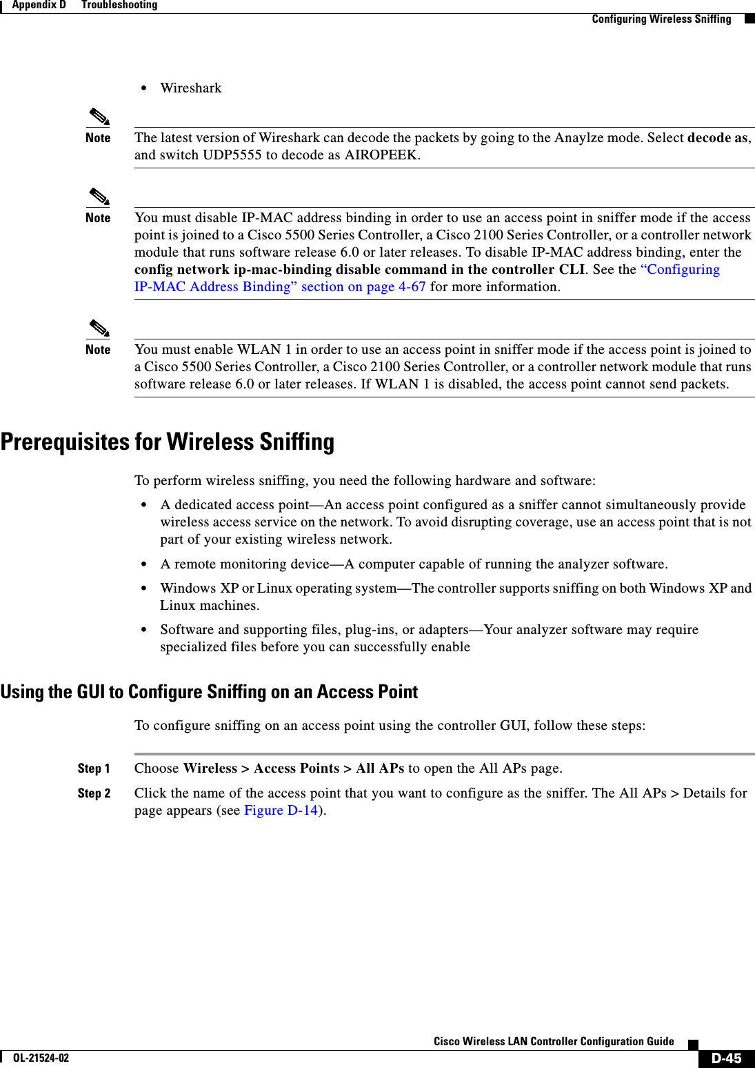
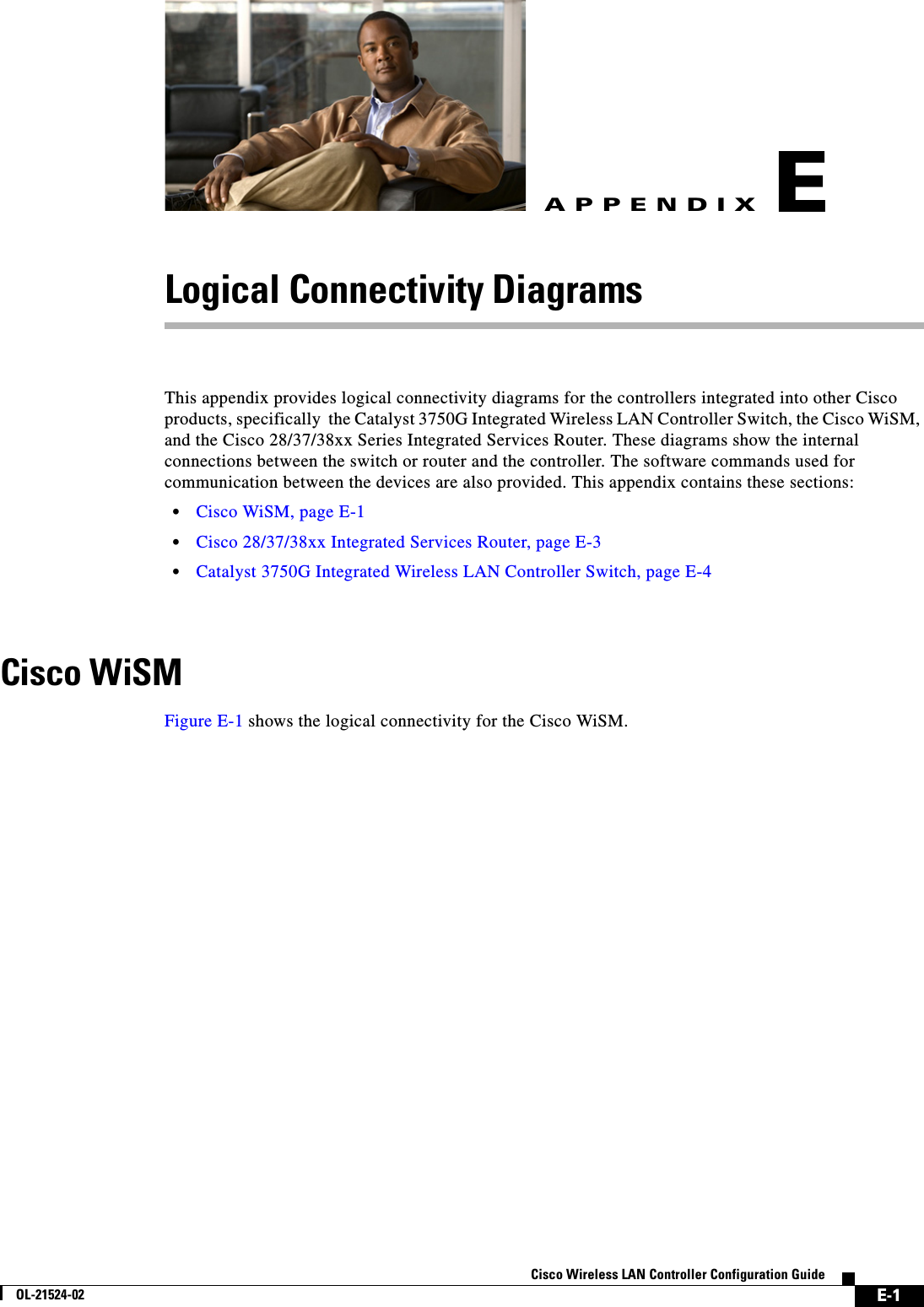
![E-3Cisco Wireless LAN Controller Configuration GuideOL-21524-02Appendix E Logical Connectivity Diagrams Cisco 28/37/38xx Integrated Services Routerhttp://www.cisco.com/en/US/docs/wireless/technology/wism/technical/reference/appnote.html#wp39498Cisco 28/37/38xx Integrated Services RouterFigure E-2 shows the logical connectivity for the Cisco 28/37/38xx integrated services router.Figure E-2 Logical Connectivity Diagram for the Cisco 28/37/38xx Integrated Services Router These commands are used for communication between the 28/37/38xx Integrated Services Router and the controller network module. They are initiated from the router. The commands vary depending on the version of the network module.These commands are used for communication between the router and Fast Ethernet versions of the controller network module: • interface wlan-controller slot/unit (and support for subinterfaces with dot1q encap) • show interfaces wlan-controller slot/unit • show controllers wlan-controller slot/unit • test service-module wlan-controller slot/unit • test HW-module wlan-controller slot/unit reset {enable | disable} • service-module wlan-controller slot/port {reload | reset | session [clear] | shutdown | status}These commands are used for communication between the router and Gigabit Ethernet versions of the controller network module: • interface integrated-service-engine slot/unit (and support for subinterfaces with dot1q encap) • show interfaces integrated-service-engine slot/unit • show controllers integrated-service-engine slot/unit • test service-module integrated-service-engine slot/unit • test HW-module integrated-service-engine slot/unit reset {enable | disable}Console28/37/38xxIntegratedServices RouterControllerNetwork ModuleRouter CPU(Cisco IOS Software)MemoryFlashInternal EthernetInterfaceInternal EthernetInterface 1 CPUCompact Flash Memory StrataFlash230621](https://usermanual.wiki/Cisco-Systems/102075.Cisco-Wireless-LAN-Controller-Configuration-Guide-10/User-Guide-1514970-Page-11.png)
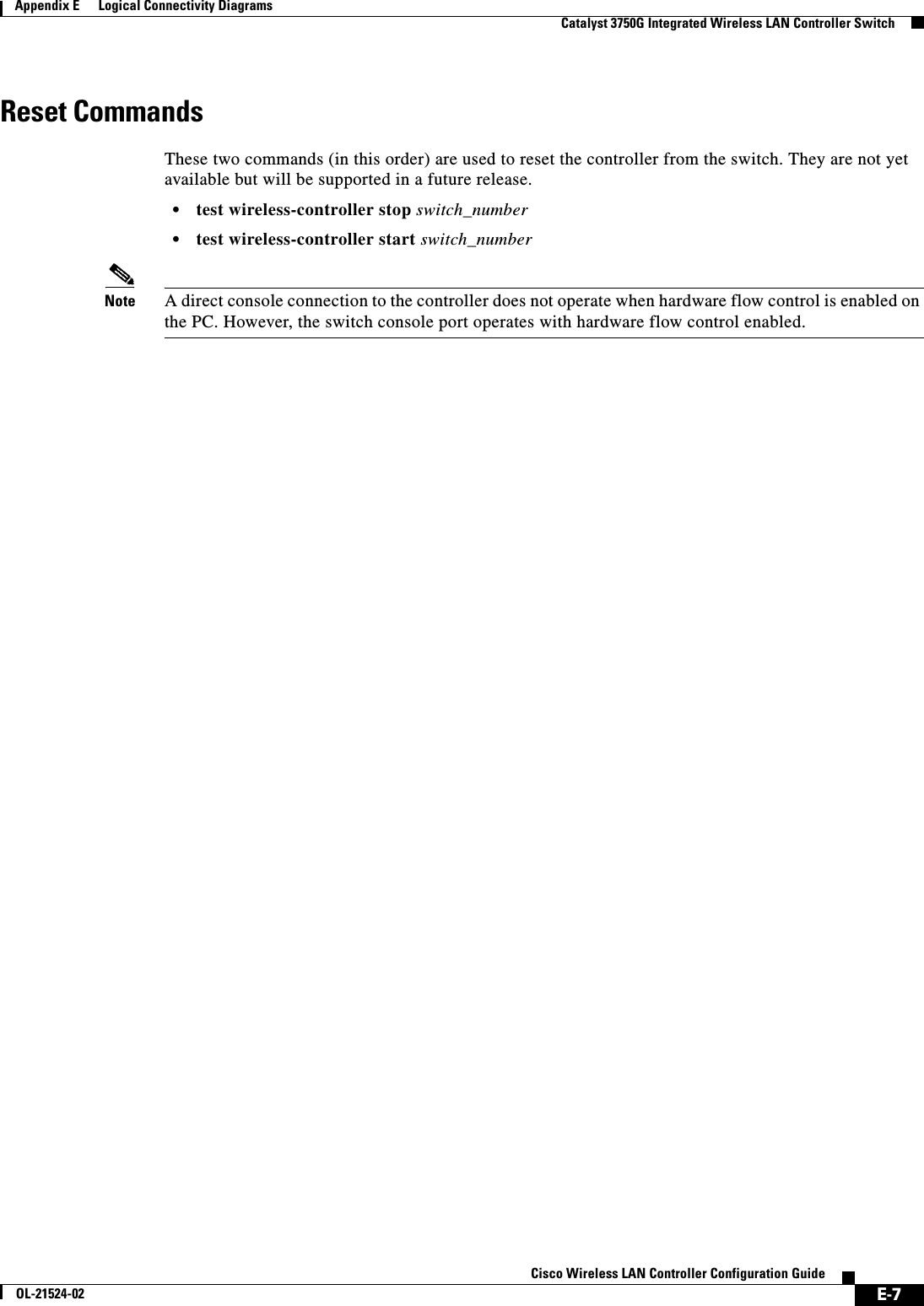
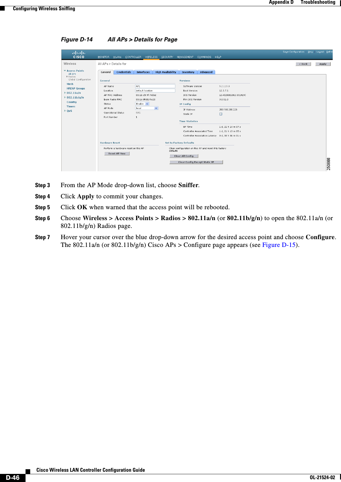
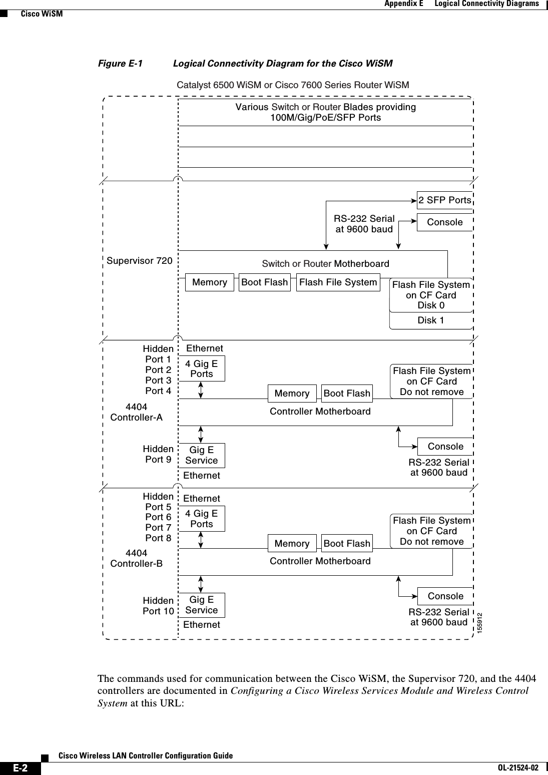
![E-4Cisco Wireless LAN Controller Configuration GuideOL-21524-02Appendix E Logical Connectivity Diagrams Catalyst 3750G Integrated Wireless LAN Controller Switch • service-module integrated-service engine slot/port {reload | reset | session [clear] | shutdown | status}Note See the Cisco Wireless LAN Controller Network Module Feature Guide for more information. You can find this document at this URL: http://www.cisco.com/univercd/cc/td/doc/product/software/ios124/124newft/124limit/124x/124xa2/boxernm.htm#wp2033271Catalyst 3750G Integrated Wireless LAN Controller SwitchFigure E-3 shows the logical connectivity for the catalyst 3750G integrated wireless LAN.Figure E-3 Logical Connectivity Diagram for the Catalyst 3750G Integrated Wireless LAN Controller Switch3750G Switch4402ControllerHiddenG1/0/27G1/0/2815591124 Gig PoE PortsSwitch MotherboardController MotherboardConsoleConsole Gig E ServiceRS-232 Serialat 9600 baudEthernet2 SFP PortsG1/0/1 through G1/0/24RS-232 Serialat 9600 baudG1/0/25G1/0/262 SFP PortsHiddenPort 1Port 22 SFP PortsMemory Boot Flash Flash File SystemMemory Boot FlashFlash File Systemon CF CardDo not remove](https://usermanual.wiki/Cisco-Systems/102075.Cisco-Wireless-LAN-Controller-Configuration-Guide-10/User-Guide-1514970-Page-12.png)