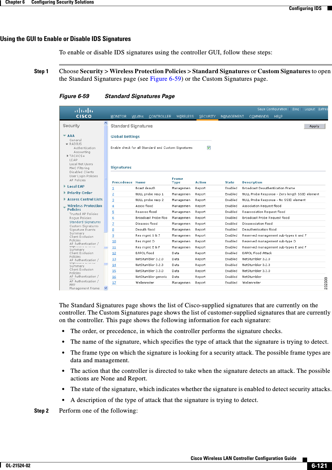
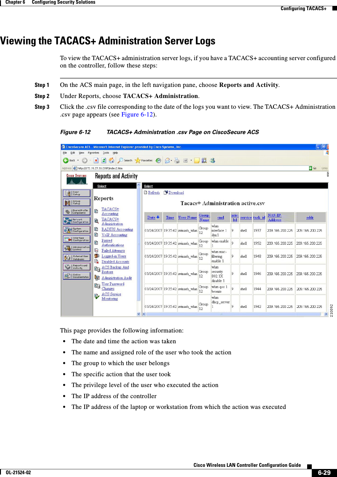
Cisco Systems 102075 Cisco Aironet 802.11n Dual Band Access Points User Manual Cisco Wireless LAN Controller Configuration Guide 3
Cisco Systems Inc Cisco Aironet 802.11n Dual Band Access Points Cisco Wireless LAN Controller Configuration Guide 3
Contents
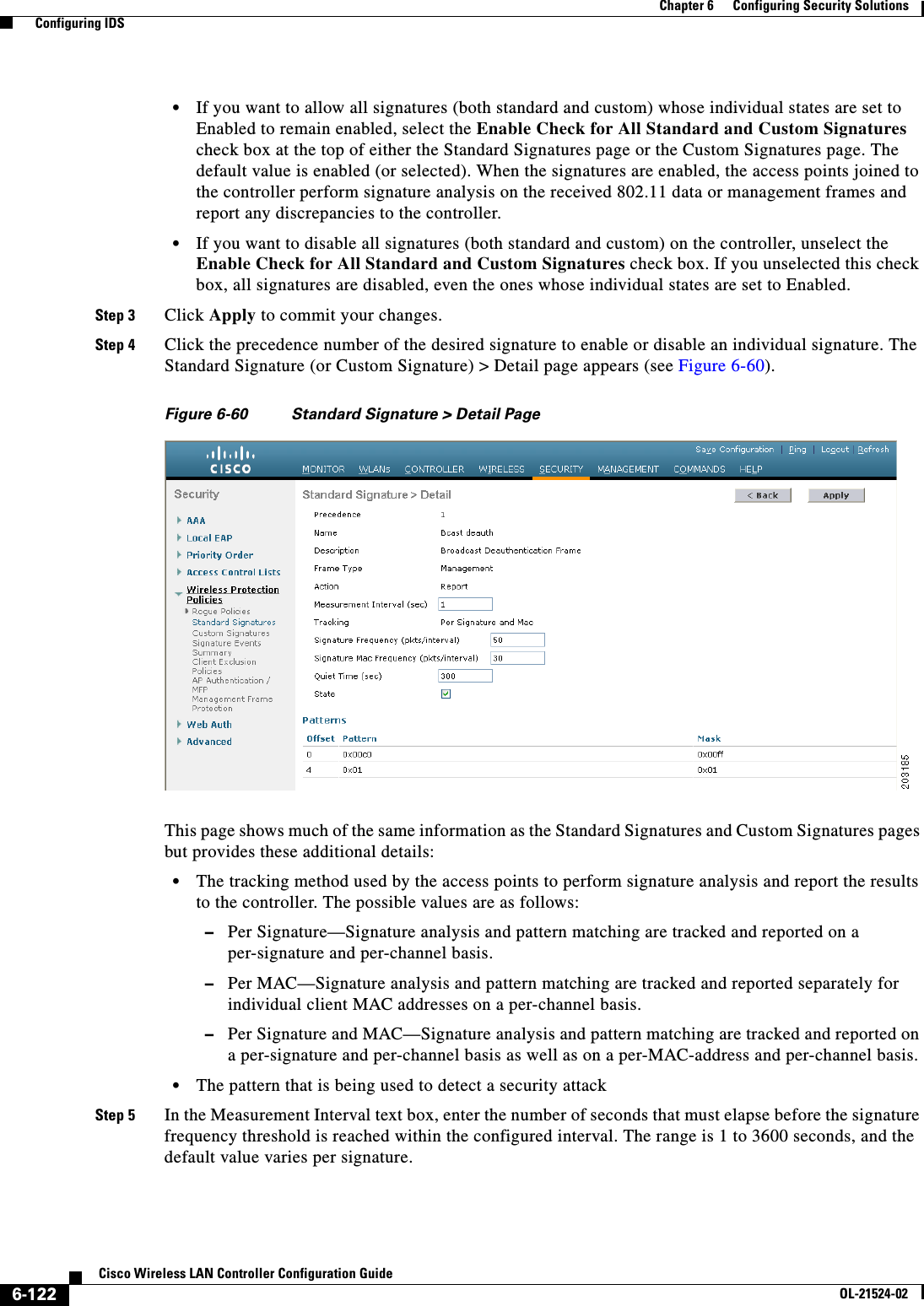
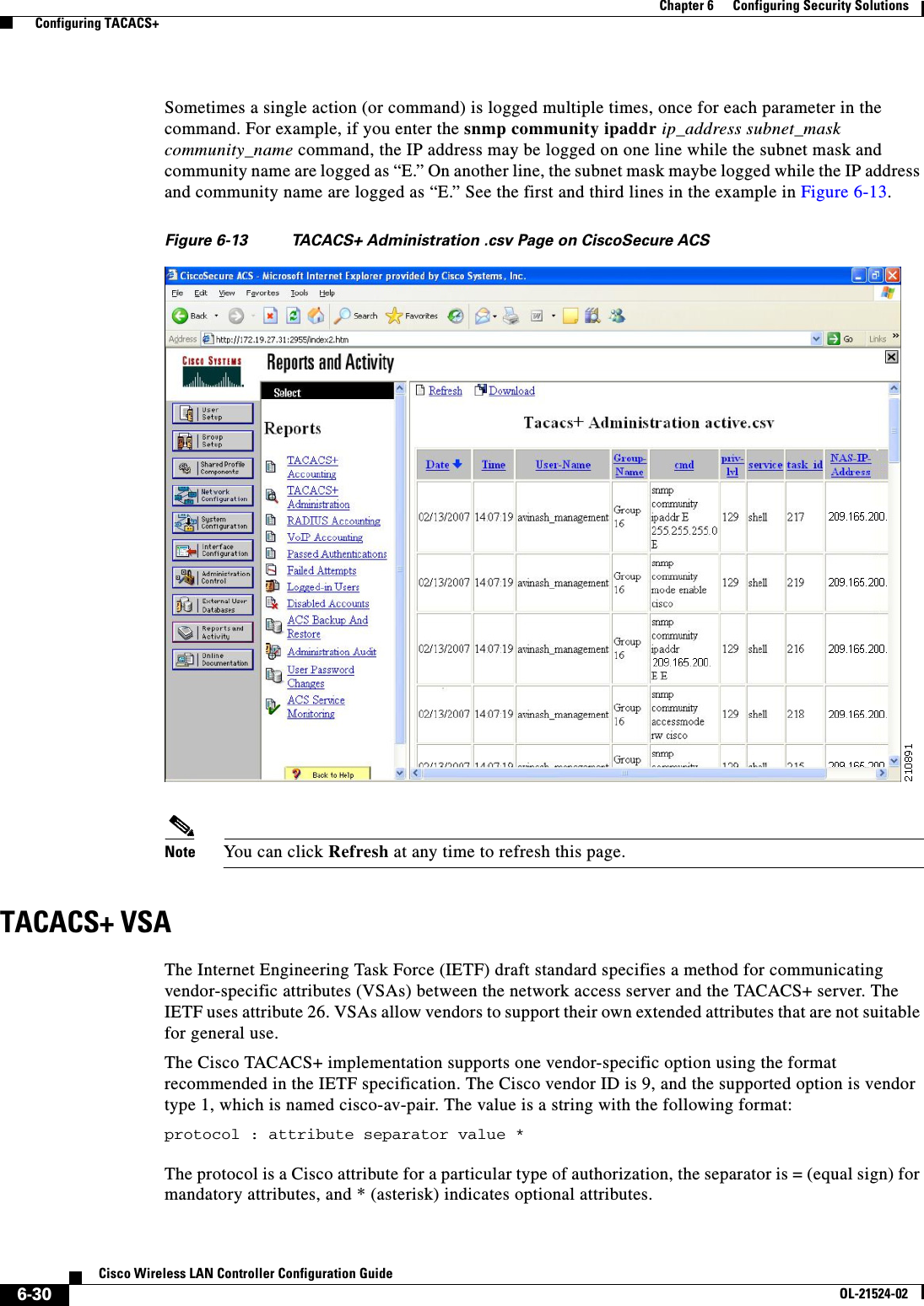
- 1. User manual
- 2. Cisco Wireless LAN Controller Configuration Guide_1
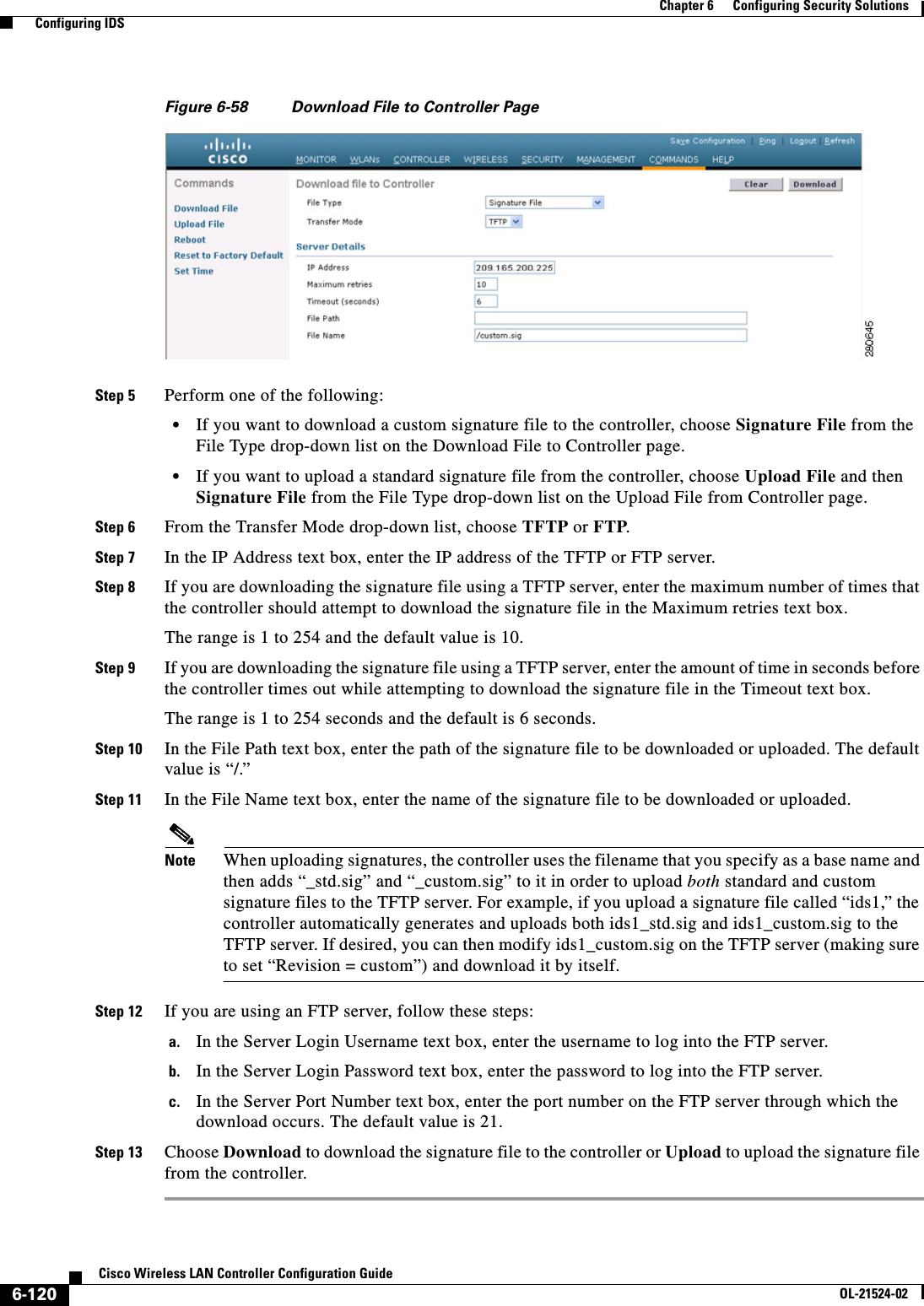
- 3. Cisco Wireless LAN Controller Configuration Guide_2
- 4. Cisco Wireless LAN Controller Configuration Guide_3
- 5. Cisco Wireless LAN Controller Configuration Guide_4
- 6. Cisco Wireless LAN Controller Configuration Guide_5
- 7. Cisco Wireless LAN Controller Configuration Guide_6
- 8. Cisco Wireless LAN Controller Configuration Guide_7
- 9. Cisco Wireless LAN Controller Configuration Guide_8
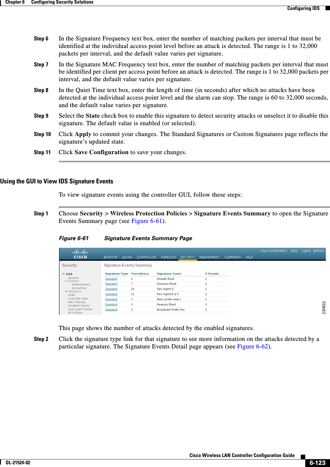
- 10. Cisco Wireless LAN Controller Configuration Guide_9
- 11. Cisco Wireless LAN Controller Configuration Guide_10
- 12. Cisco Wireless LAN Controller Configuration Guide_11
- 13. User Manual
Cisco Wireless LAN Controller Configuration Guide_3
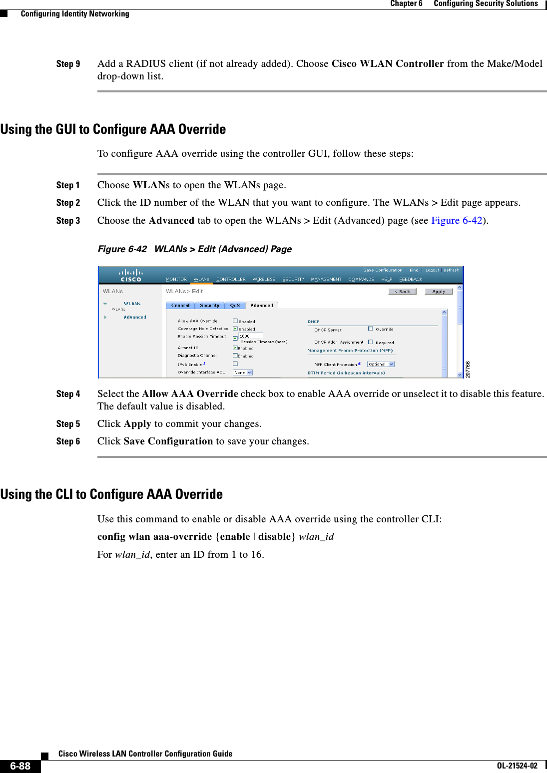
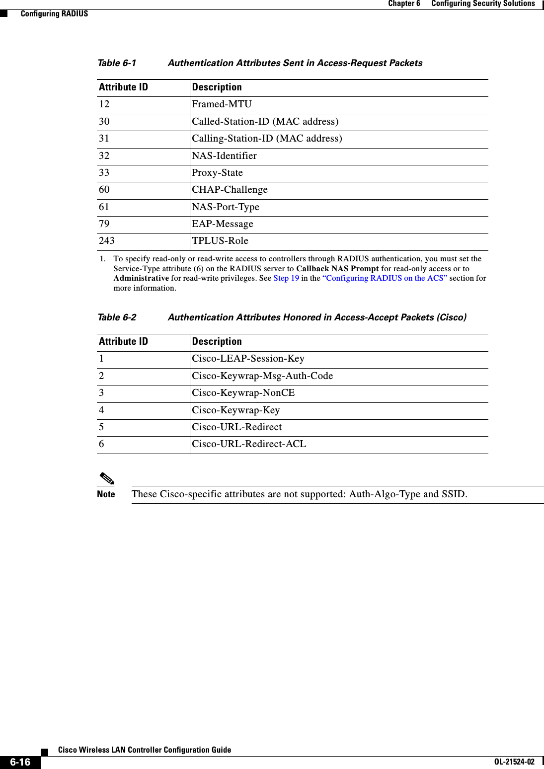
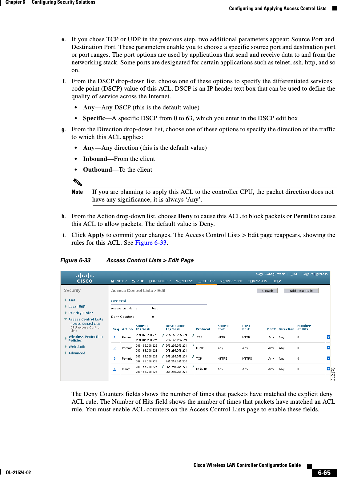
![5-9Cisco Wireless LAN Controller Configuration GuideOL-21524-02Chapter 5 Configuring VideoStream Configuring VideoStreamStep 3 Configure various message configuration parameters by entering this command:config media-stream message {state [enable | disable] | url url | email email | phone phone _number | note note}Step 4 Save your changes by entering this command:save configStep 5 Configure various global media-stream configurations by entering this commands:config media-stream add multicast-direct stream-name media_stream_name start_IP end_IP [template {very-coarse | coarse | ordinary | low-resolution | med-resolution | high-resolution} | detail {Max_bandwidth bandwidth | packet size packet_size | Re-evaluation re-evaluation {periodic | initial}} video video priority {drop | fallback}Note • The Resource Reservation Control (RRC) parameters are assigned with the predefined values based on the values assigned to the template. • The following templates are used to assign RRC parameters to the media stream: –Very Coarse (below 3000 kbps) –Coarse (below 500 kbps) –Ordinary (below 750 kbps) –Low Resolution (below 1 mbps) –Medium Resolution (below 3 mbps) –High Resolution (below 5 mbps)Step 6 Delete a media stream by entering this command:config media-stream delete media_stream_nameStep 7 Enable a specific enhanced distributed channel access (EDC) profile by entering this command:config advanced {801.11a | 802.11b} edca-parameters optimized-video-voiceStep 8 Enable the admission control on desired bandwidth by entering the following commands: • Enable bandwidth-based voice CAC for 802.11a or 802.11b/g network by entering this command:config {802.11a | 802.11b} cac voice acm enable • Set the percentage of the maximum bandwidth allocated to clients for voice applications on the 802.11a or 802.11b/g network by entering this command:config {802.11a | 802.11b} cac voice max-bandwidth bandwidth • Configure the percentage of the maximum allocated bandwidth reserved for roaming voice clients on the 802.11a or 802.11b/g network by entering this command:config {802.11a | 802.11b} cac voice roam-bandwidth bandwidthStep 9 Set the maximum number of streams per radio and/or per client by entering the following commands: • Set the maximum limit to the number multicast streams per radio by entering this command:config {802.11a | 802.11b} media-stream multicast-direct radio-maximum [value | ‘no-limit’] • Set the maximum number of multicast streams per client by entering this command:config {802.11a | 802.11b} media-stream multicast-direct client-maximum [value | ‘no-limit’]Step 10 Save your changes by entering this command:](https://usermanual.wiki/Cisco-Systems/102075.Cisco-Wireless-LAN-Controller-Configuration-Guide-3/User-Guide-1514963-Page-3.png)
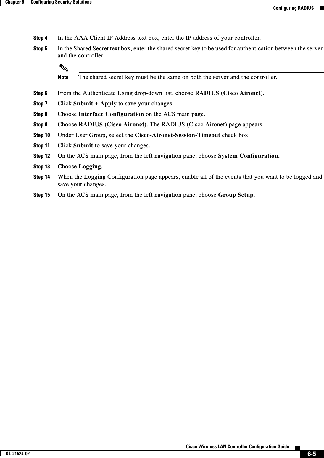
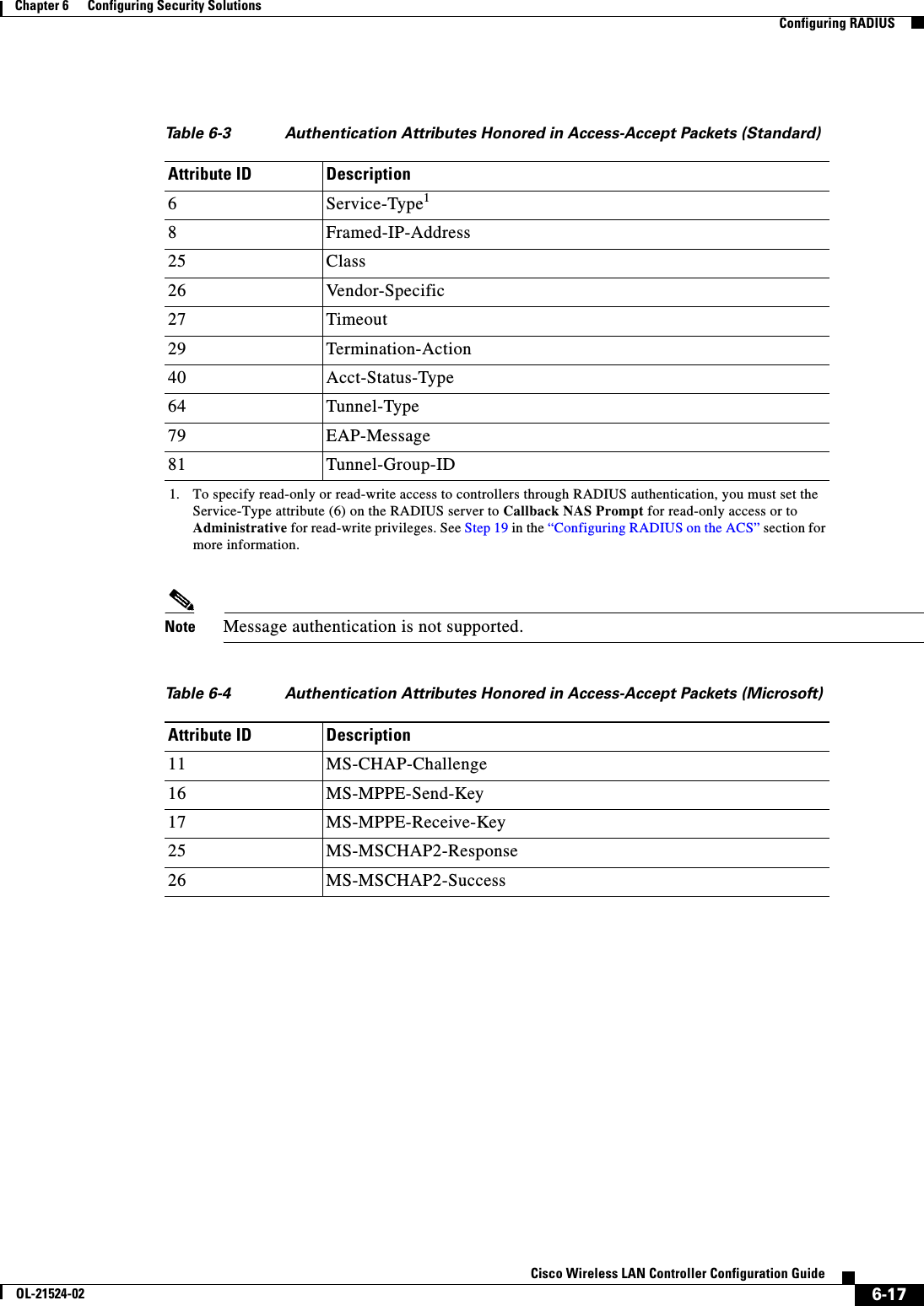
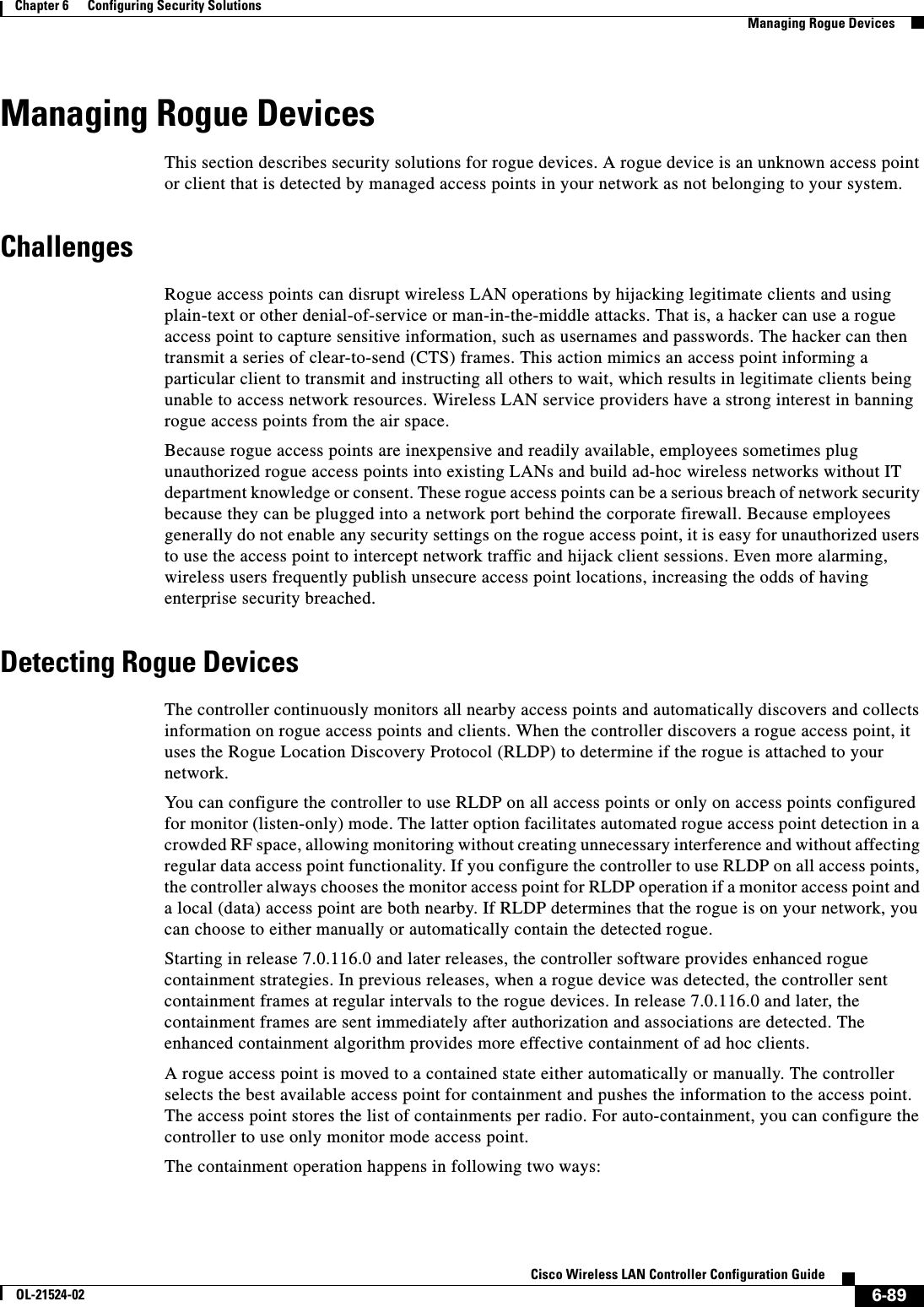
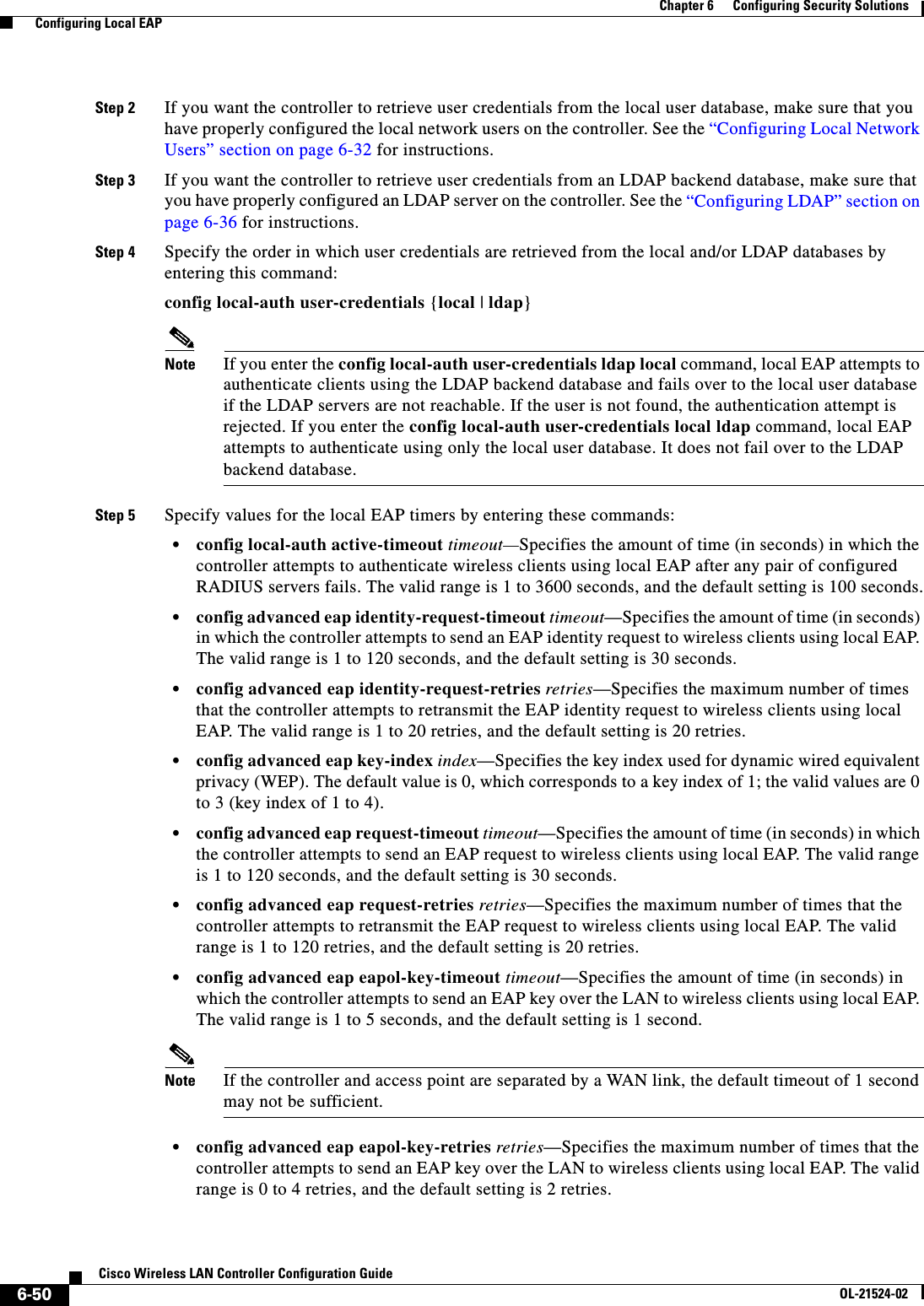
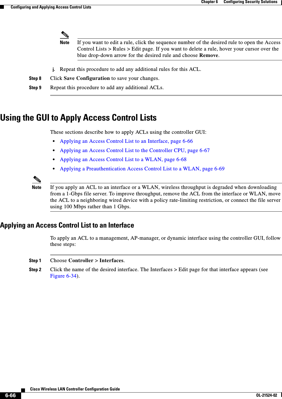
![6-28Cisco Wireless LAN Controller Configuration GuideOL-21524-02Chapter 6 Configuring Security Solutions Configuring TACACS+1 11.11.12.2 49 Enabled 5 2 11.11.13.2 49 Enabled 5 3 11.11.14.2 49 Enabled 5 Accounting Servers Idx Server Address Port State Tout--- ---------------- ------ -------- ----1 11.11.12.2 49 Enabled 5 2 11.11.13.2 49 Enabled 5 3 11.11.14.2 49 Enabled 5Information similar to the following appears when you enter the show tacacs auth stats command:Server Index..................................... 1Server Address................................... 10.10.10.10Msg Round Trip Time.............................. 0 (msec)First Requests................................... 0Retry Requests................................... 0Accept Responses................................. 0Reject Responses................................. 0Error Responses.................................. 0Restart Responses................................ 0Follow Responses................................. 0GetData Responses................................ 0Encrypt no secret Responses...................... 0Challenge Responses.............................. 0Malformed Msgs................................... 0Bad Authenticator Msgs........................... 0Pending Requests................................. 0Timeout Requests................................. 0Unknowntype Msgs................................. 0Other Drops....................................0 • Clear the statistics for one or more TACACS+ servers by entering this command:clear stats tacacs [auth | athr | acct] {index | all} • Configure the order of authentication when multiple databases are configured by entering this command. The default setting is local and then radius.config aaa auth mgmt [radius | tacacs]See the current management authentication server order by entering this command:show aaa authInformation similar to the following appears:Management authentication server order: 1............................................ local 2......................................... tacacs • Make sure the controller can reach the TACACS+ server by entering this command:ping server_ip_address • Enable or disable TACACS+ debugging by entering this command:debug aaa tacacs {enable | disable} • Save your changes by entering this command:save config](https://usermanual.wiki/Cisco-Systems/102075.Cisco-Wireless-LAN-Controller-Configuration-Guide-3/User-Guide-1514963-Page-32.png)
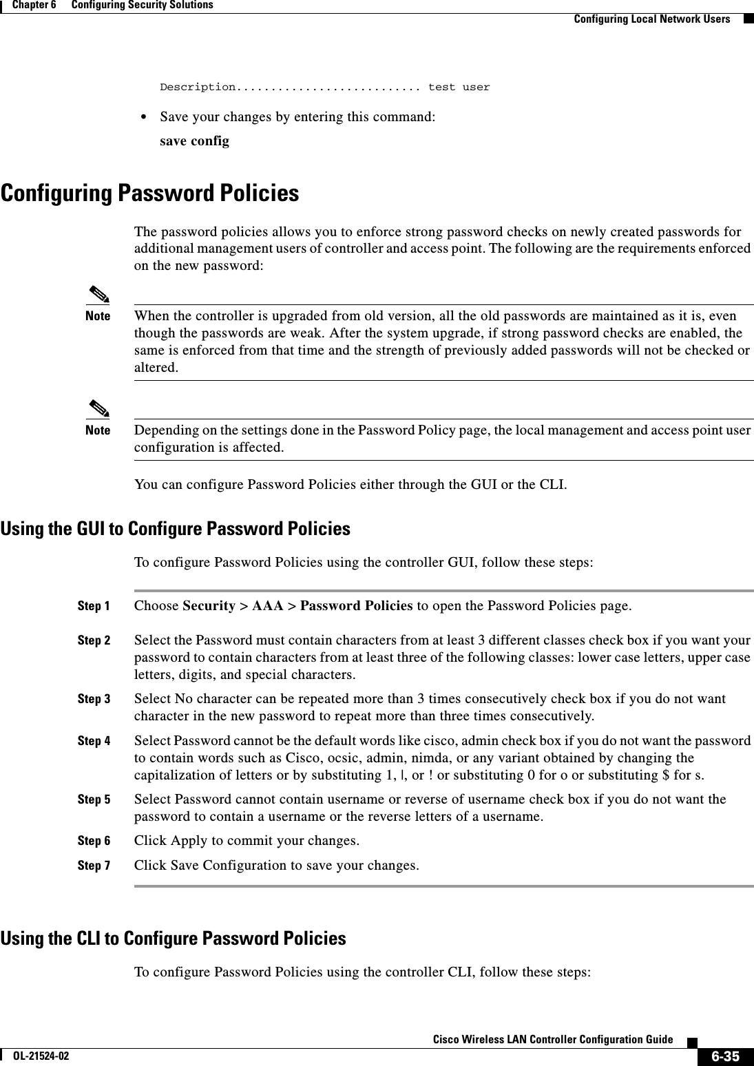
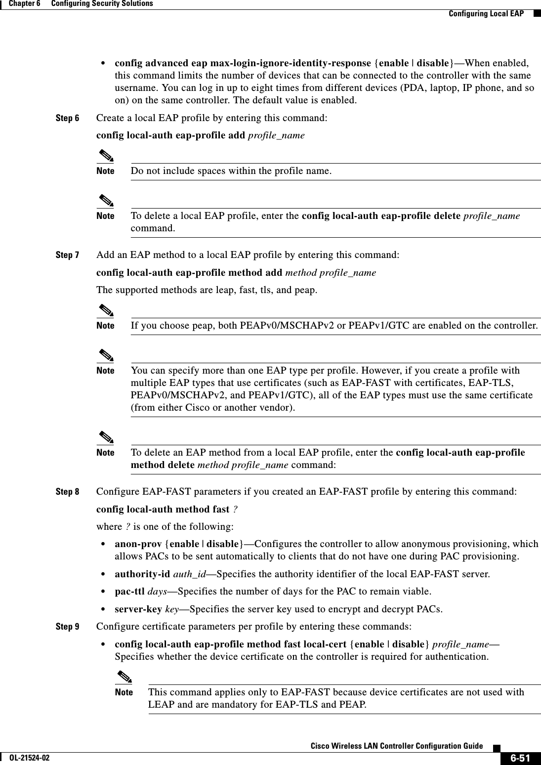
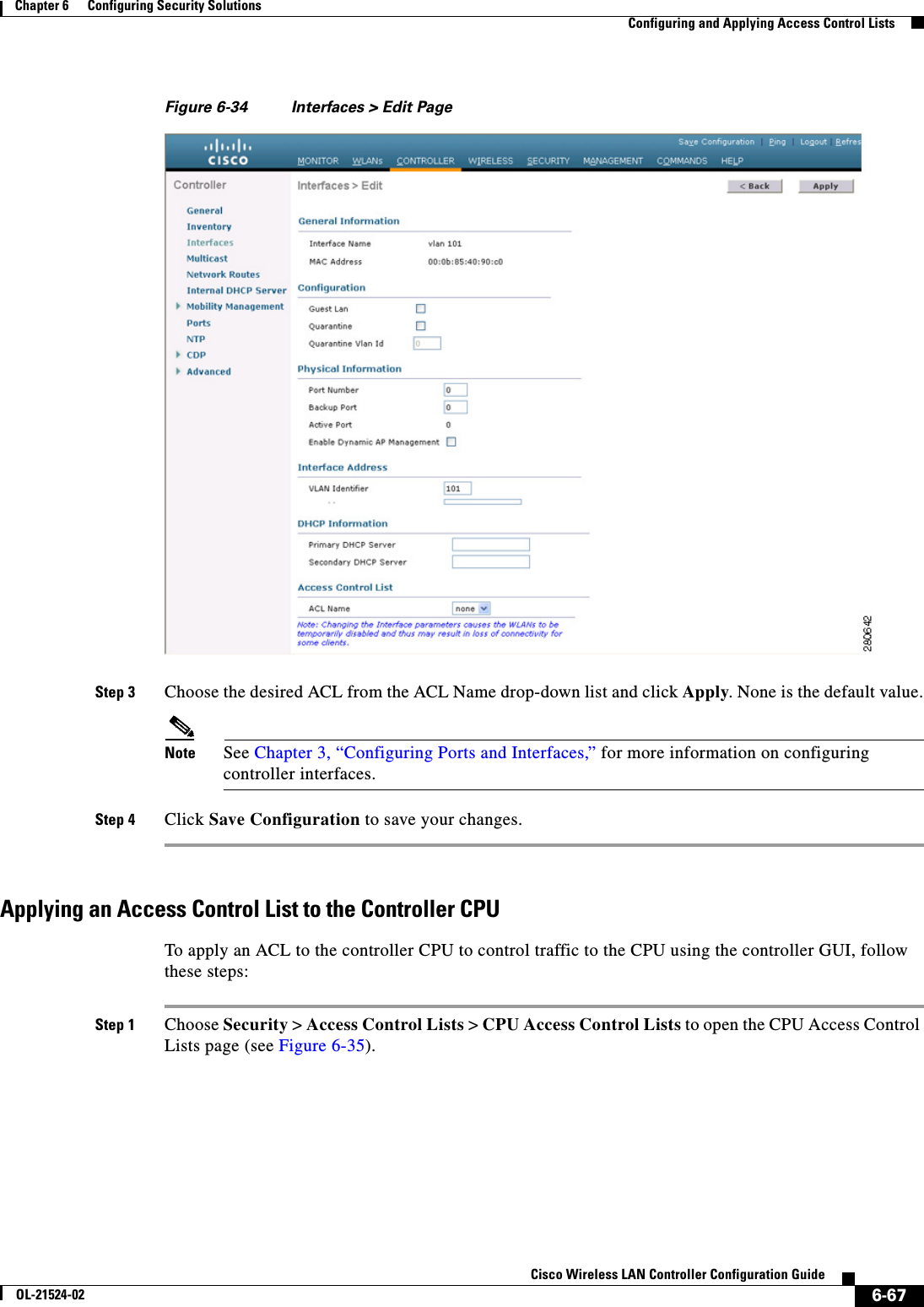
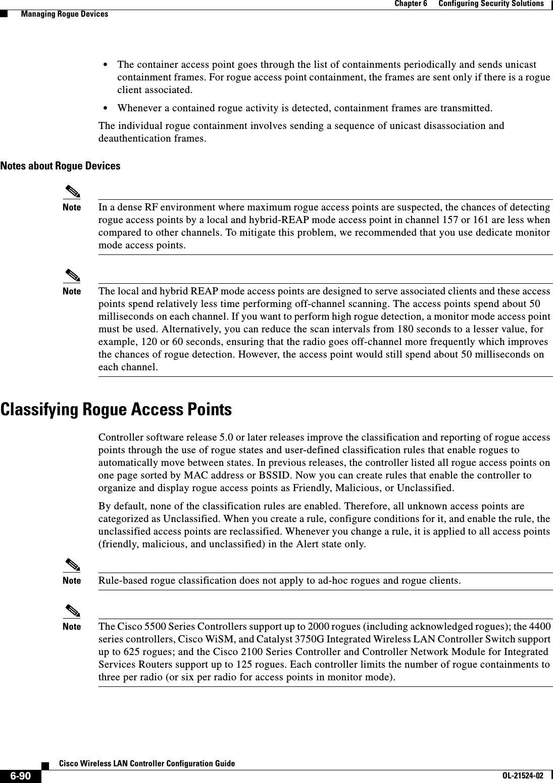
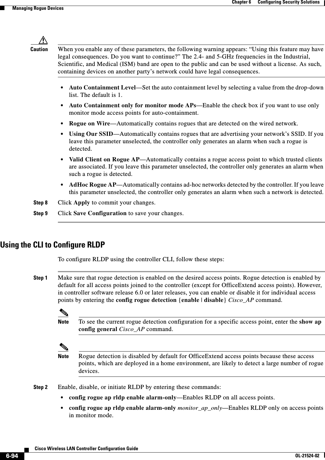
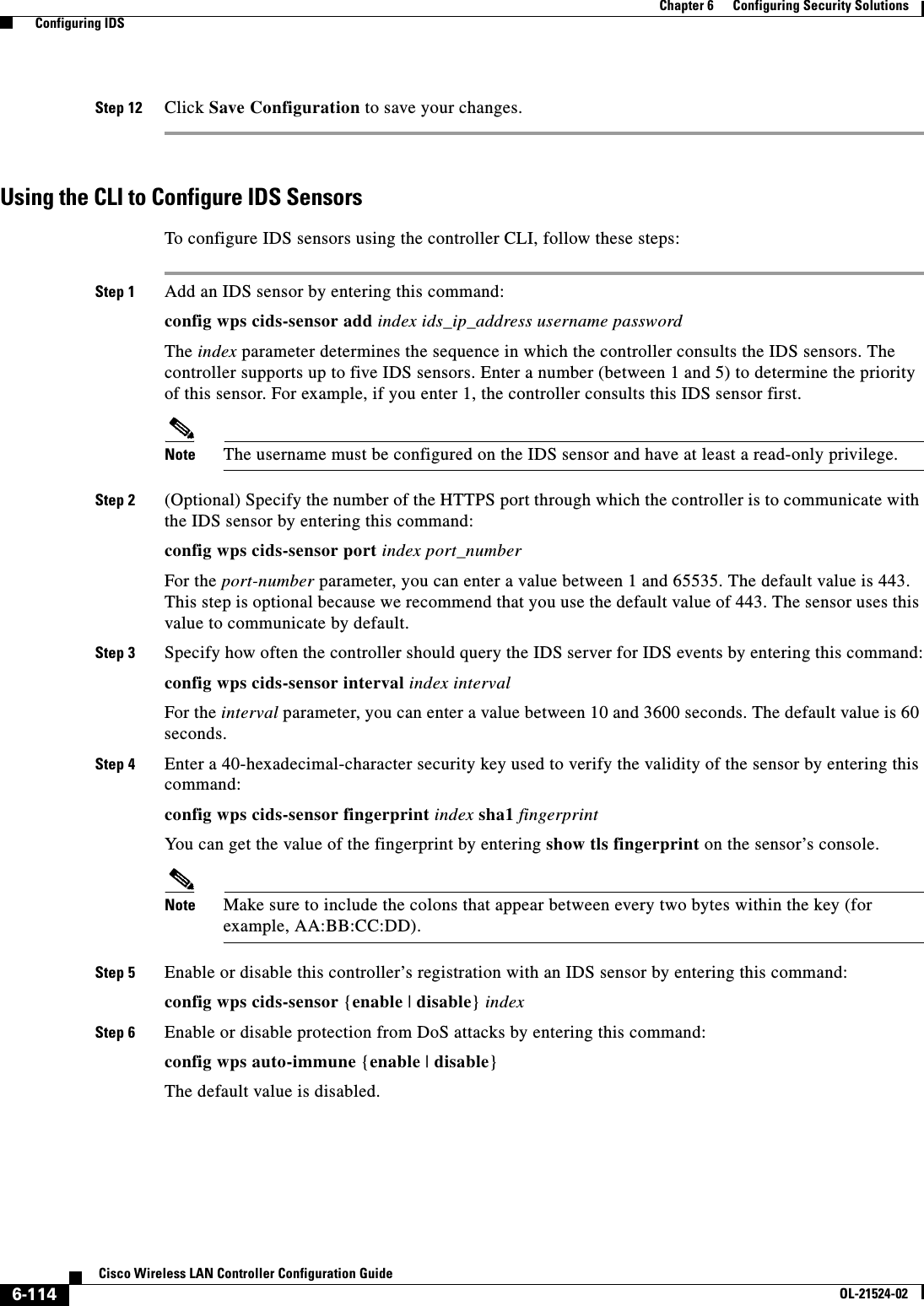
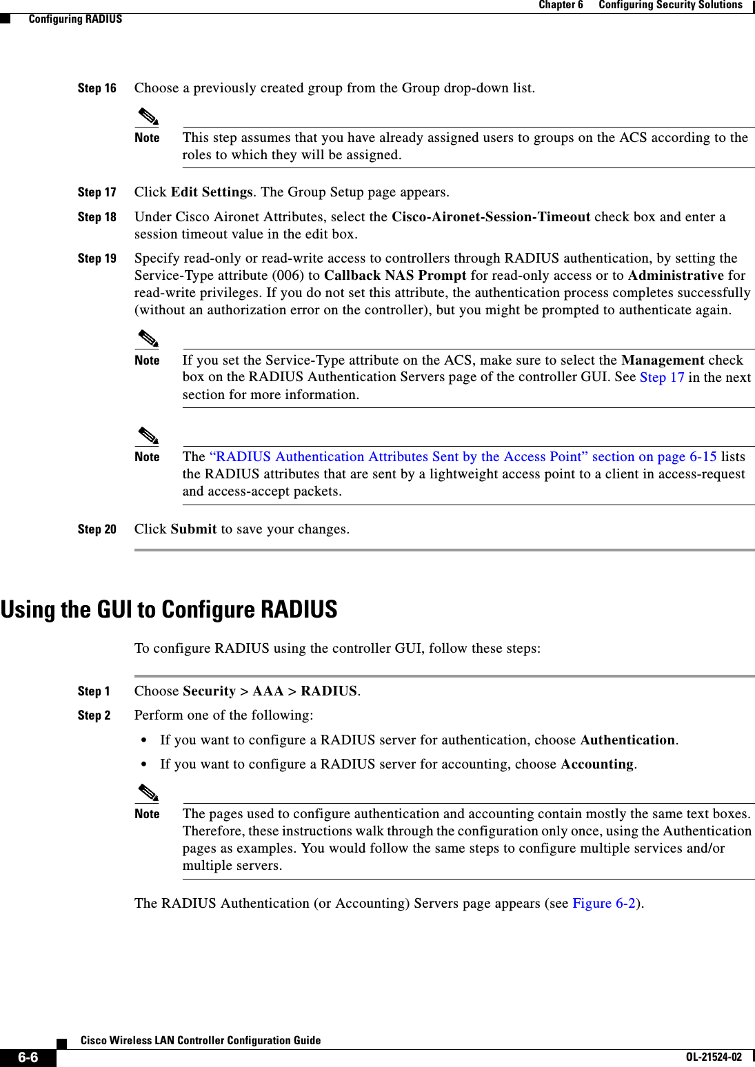
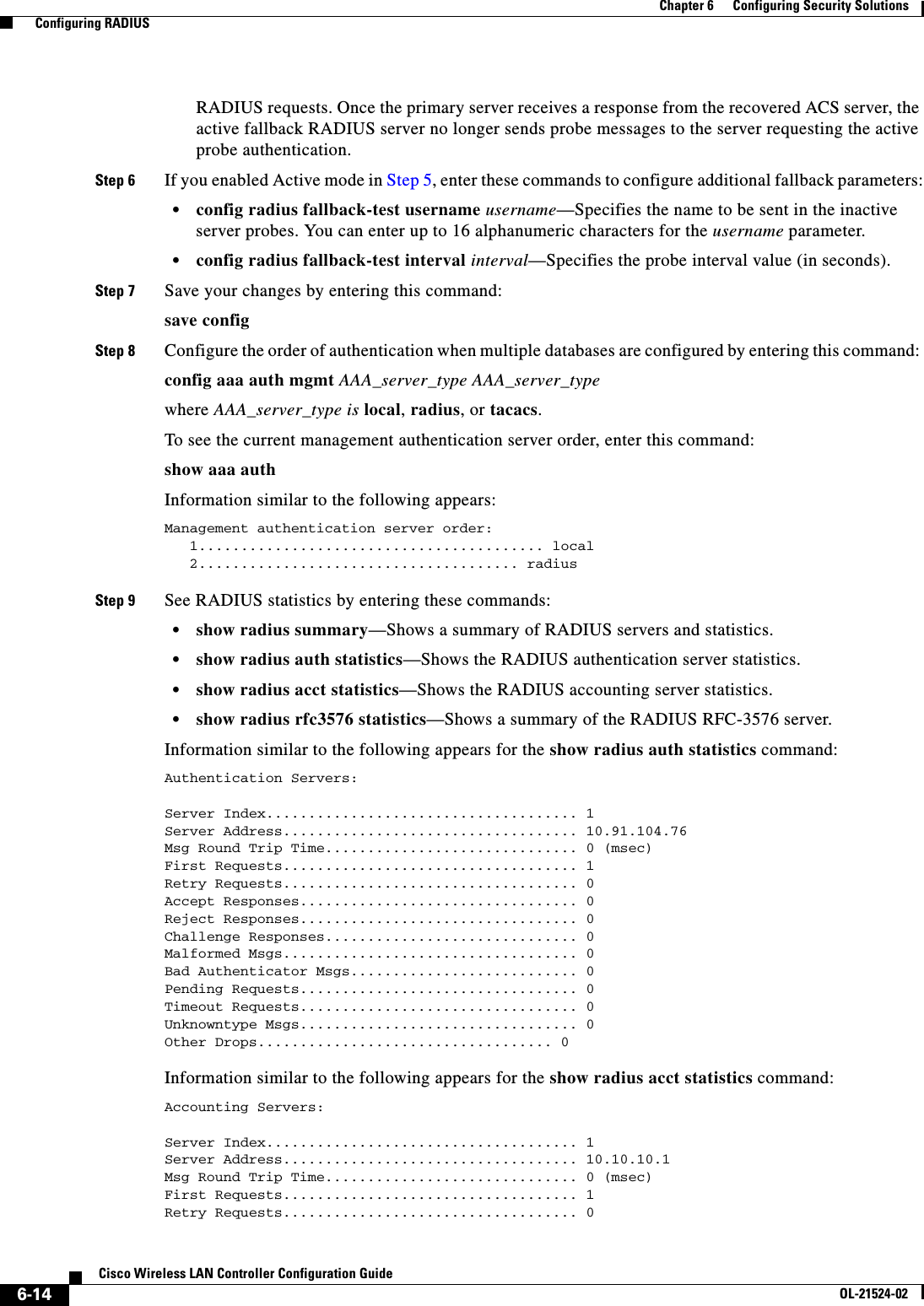
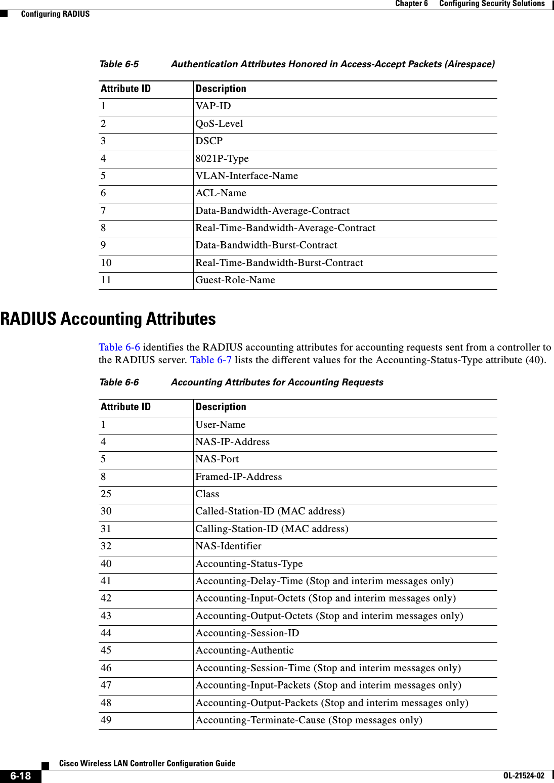
![6-77Cisco Wireless LAN Controller Configuration GuideOL-21524-02Chapter 6 Configuring Security Solutions Using the GUI to Configure MFPFigure 6-40 Management Frame Protection Settings PageOn this page, you can see the following MFP settings: • The Management Frame Protection field shows if infrastructure MFP is enabled globally for the controller. • The Controller Time Source Valid field indicates whether the controller time is set locally (by manually entering the time) or through an external source (such as the NTP server). If the time is set by an external source, the value of this field is “True.” If the time is set locally, the value is “False.” The time source is used for validating the timestamp on management frames between access points of different controllers within a mobility group. • The Infrastructure Protection field shows if infrastructure MFP is enabled for individual WLANs. • The Client Protection field shows if client MFP is enabled for individual WLANs and whether it is optional or required. • The Infrastructure Validation text box shows if infrastructure MFP is enabled for individual access points.Using the CLI to Configure MFPTo configure MFP using the controller CLI, use these commands: • Enable or disable infrastructure MFP globally for the controller by entering this command:config wps mfp infrastructure {enable | disable} • Enable or disable infrastructure MFP validation on an access point by entering this command:config ap mfp infrastructure validation {enable | disable} Cisco_APNote MFP validation is activated only if infrastructure MFP is globally enabled. • Enable or disable client MFP on a specific WLAN by entering this command:config wlan mfp client {enable | disable} wlan_id [required]If you enable client MFP and use the optional required parameter, clients are allowed to associate only if MFP is negotiated.](https://usermanual.wiki/Cisco-Systems/102075.Cisco-Wireless-LAN-Controller-Configuration-Guide-3/User-Guide-1514963-Page-81.png)
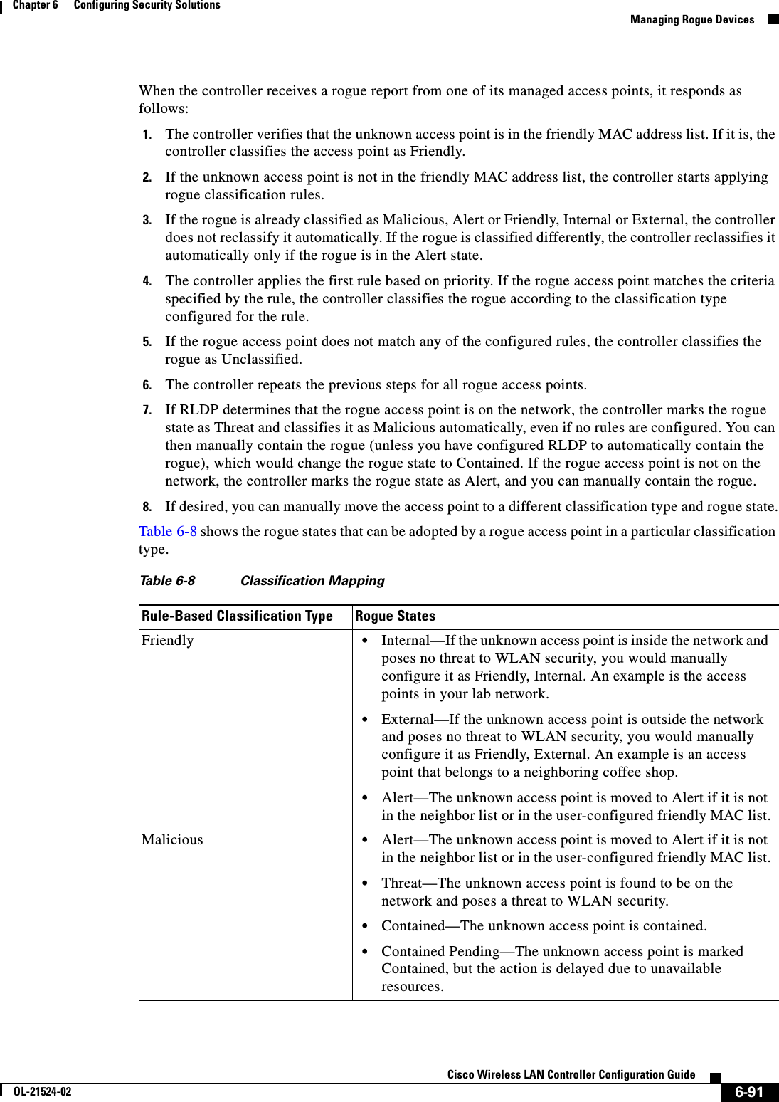
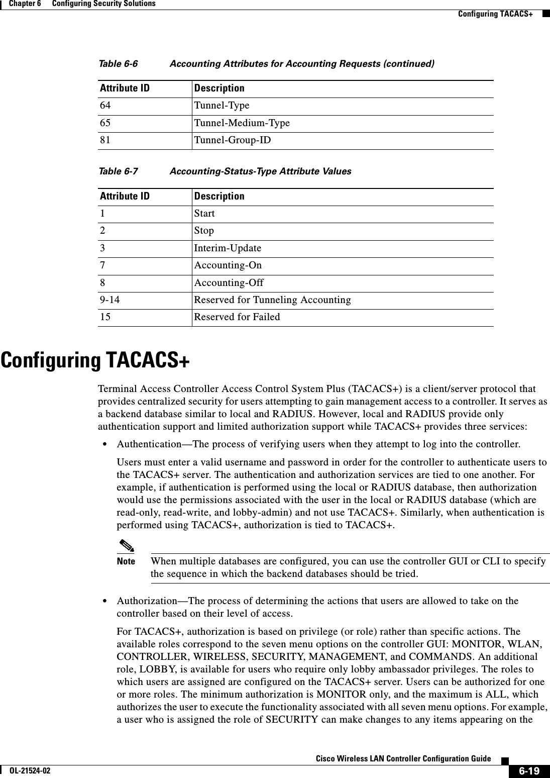
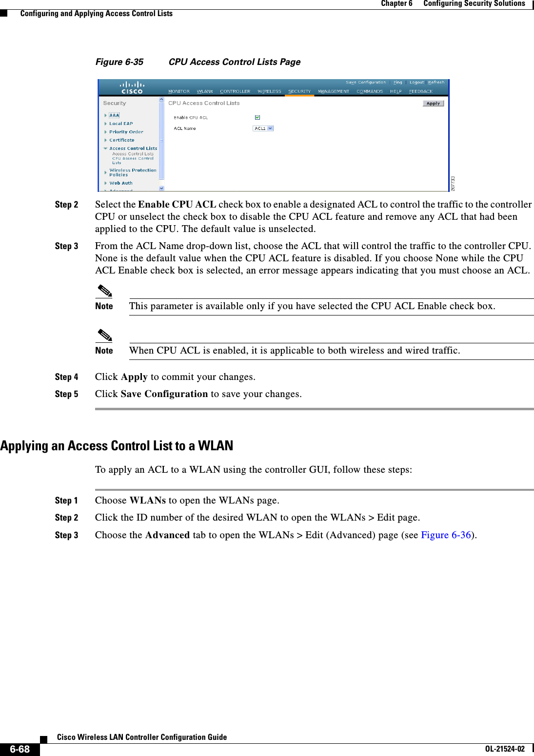
![6-81Cisco Wireless LAN Controller Configuration GuideOL-21524-02Chapter 6 Configuring Security Solutions Configuring Client Exclusion PoliciesStep 2 Select any of these check boxes if you want the controller to exclude clients for the condition specified. The default value for each exclusion policy is enabled. • Excessive 802.11 Association Failures—Clients are excluded on the sixth 802.11 association attempt, after five consecutive failures. • Excessive 802.11 Authentication Failures—Clients are excluded on the sixth 802.11 authentication attempt, after five consecutive failures. • Excessive 802.1X Authentication Failures—Clients are excluded on the fourth 802.1X authentication attempt, after three consecutive failures. • IP Theft or IP Reuse—Clients are excluded if the IP address is already assigned to another device. • Excessive Web Authentication Failures—Clients are excluded on the fourth web authentication attempt, after three consecutive failures.Step 3 Click Apply to commit your changes.Step 4 Click Save Configuration to save your changes.Using the CLI to Configure Client Exclusion PoliciesTo configure client exclusion policies using the controller CLI, follow these steps:Step 1 Enable or disable the controller to exclude clients on the sixth 802.11 association attempt, after five consecutive failures by entering this command:config wps client-exclusion 802.11-assoc {enable | disable}Step 2 Enable or disable the controller to exclude clients on the sixth 802.11 authentication attempt, after five consecutive failures by entering this command:config wps client-exclusion 802.11-auth {enable | disable}Step 3 Enable or disable the controller to exclude clients on the fourth 802.1X authentication attempt, after three consecutive failures by entering this command:config wps client-exclusion 802.1x-auth {enable | disable}Step 4 Enable or disable the controller to exclude clients if the IP address is already assigned to another device by entering this command:config wps client-exclusion ip-theft {enable | disable}Step 5 Enable or disable the controller to exclude clients on the fourth web authentication attempt, after three consecutive failures by entering this command:config wps client-exclusion web-auth {enable | disable}Step 6 Enable or disable the controller to exclude clients for all of the above reasons by entering this command:config wps client-exclusion all {enable | disable}Step 7 Use the following command to add or delete client exclusion entries.config exclusionlist {add MAC [description] | delete MAC | description MAC [description]}Step 8 Save your changes by entering this command:save configStep 9 See a list of clients that have been dynamically excluded, by entering this command:](https://usermanual.wiki/Cisco-Systems/102075.Cisco-Wireless-LAN-Controller-Configuration-Guide-3/User-Guide-1514963-Page-85.png)
![6-87Cisco Wireless LAN Controller Configuration GuideOL-21524-02Chapter 6 Configuring Security Solutions Configuring Identity NetworkingNote This issue does not apply to the Cisco Secure Access Control Server (ACS).To update the RADIUS server dictionary file, follow these steps:Step 1 Stop the SBR service (or other RADIUS service).Step 2 Save the following text to the Radius_Install_Directory\Service folder as ciscowlan.dct:################################################################################# CiscoWLAN.dct- Cisco Wireless Lan Controllers# # (See README.DCT for more details on the format of this file)################################################################################# Dictionary - Cisco WLAN Controllers## Start with the standard Radius specification attributes#@radius.dct## Standard attributes supported by Airespace## Define additional vendor specific attributes (VSAs)#MACRO Airespace-VSA(t,s) 26 [vid=14179 type1=%t% len1=+2 data=%s%]ATTRIBUTE WLAN-Id Airespace-VSA(1, integer) crATTRIBUTE Aire-QoS-Level Airespace-VSA(2, integer) rVALUE Aire-QoS-Level Bronze 3VALUE Aire-QoS-Level Silver 0VALUE Aire-QoS-Level Gold 1VALUE Aire-QoS-Level Platinum 2ATTRIBUTE DSCP Airespace-VSA(3, integer) rATTRIBUTE 802.1P-Tag Airespace-VSA(4, integer) rATTRIBUTE Interface-Name Airespace-VSA(5, string) rATTRIBUTE ACL-Name Airespace-VSA(6, string) r# This should be last.################################################################################# CiscoWLAN.dct - Cisco WLC dictionary############################################################################## Step 3 Open the dictiona.dcm file (in the same directory) and add the line “@ciscowlan.dct.”Step 4 Save and close the dictiona.dcm file.Step 5 Open the vendor.ini file (in the same directory) and add the following text:vendor-product = Cisco WLAN Controllerdictionary = ciscowlanignore-ports = noport-number-usage = per-port-typehelp-id = Step 6 Save and close the vendor.ini file.Step 7 Start the SBR service (or other RADIUS service).Step 8 Launch the SBR Administrator (or other RADIUS Administrator).](https://usermanual.wiki/Cisco-Systems/102075.Cisco-Wireless-LAN-Controller-Configuration-Guide-3/User-Guide-1514963-Page-91.png)