Cisco Systems 102075 Cisco Aironet 802.11n Dual Band Access Points User Manual Cisco Wireless LAN Controller Configuration Guide 3
Cisco Systems Inc Cisco Aironet 802.11n Dual Band Access Points Cisco Wireless LAN Controller Configuration Guide 3
Contents
- 1. User manual
- 2. Cisco Wireless LAN Controller Configuration Guide_1
- 3. Cisco Wireless LAN Controller Configuration Guide_2
- 4. Cisco Wireless LAN Controller Configuration Guide_3
- 5. Cisco Wireless LAN Controller Configuration Guide_4
- 6. Cisco Wireless LAN Controller Configuration Guide_5
- 7. Cisco Wireless LAN Controller Configuration Guide_6
- 8. Cisco Wireless LAN Controller Configuration Guide_7
- 9. Cisco Wireless LAN Controller Configuration Guide_8
- 10. Cisco Wireless LAN Controller Configuration Guide_9
- 11. Cisco Wireless LAN Controller Configuration Guide_10
- 12. Cisco Wireless LAN Controller Configuration Guide_11
- 13. User Manual
Cisco Wireless LAN Controller Configuration Guide_3
5-7
Cisco Wireless LAN Controller Configuration Guide
OL-21524-02
Chapter 5 Configuring VideoStream
Configuring VideoStream
The range is 5 to 85%.
The default value is 9%.
Step 32 Click Apply to commit your changes.
Step 33 Reenable all WMM WLANs and click Apply.
Note To configure the media bandwidth using the controller GUI, perform Step 34 through Step 44.
Step 34 Choose Wireless > 802.11a/n or 802.11b/g/n > Media to open the 802.11a (or 802.11b) > Media >
Parameters page.
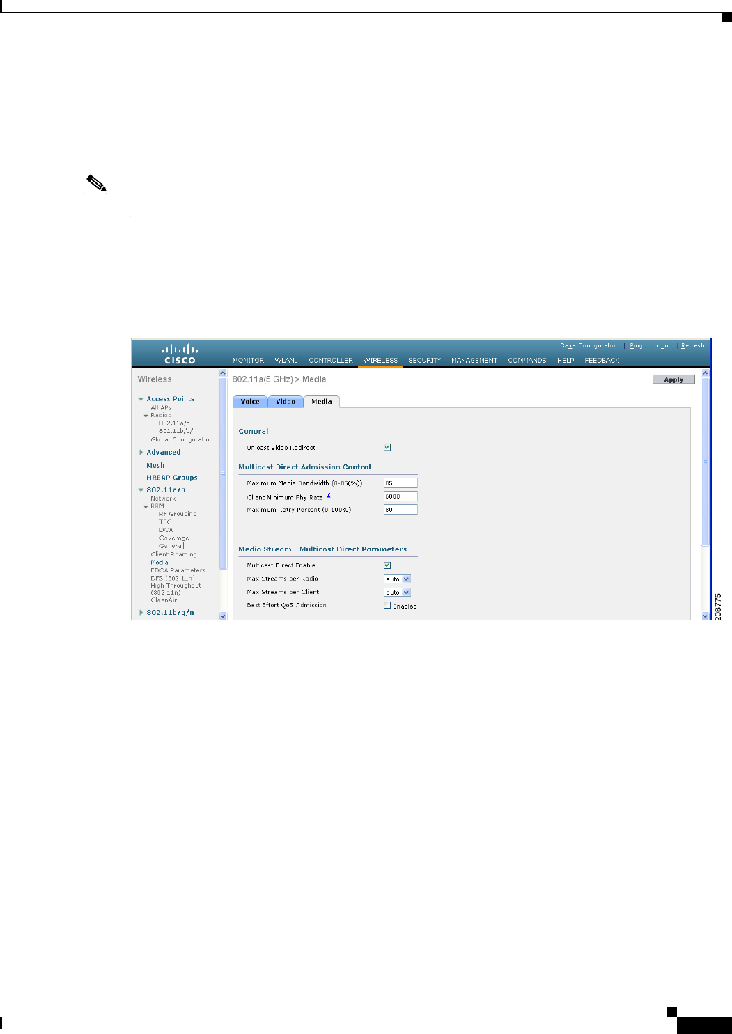
Step 35 Choose the Media tab to open the Media page (see Figure 5-5).
Figure 5-5 Media Streams Page
Step 36 Select the Unicast Video Redirect check box to enable Unicast Video Redirect. The default value is
disabled.
Step 37 In the Maximum Media Bandwidth (0-85%) text box, enter the percentage of the maximum bandwidth
to be allocated for media applications on this radio band. Once the client reaches a specified value, the
access point rejects new calls on this radio band.
The default value is 85%; valid values are from 0 to 85%.
Step 38 In the Client Phy Rate field, enter the minimum transmission data rate to the client. If the transmission
data rate is below the phy rate, either the video will not start or the client may be classified as a bad client.
The bad client video can be demoted for better effort QoS or subject to denial.
Step 39 In the Maximum Retry Percent (0-100%) field, enter the percentage of maximum retries that are allowed.
The default value is 80. If it exceeds 80, either the video will not start or client may be classified as a
bad client. The bad client video can be demoted for better effort QoS or subject to denial.
Step 40 Select the Multicast Direct Enable check box to enable the Multicast Direct Enable field. The default
value is enabled.

5-8
Cisco Wireless LAN Controller Configuration Guide
OL-21524-02
Chapter 5 Configuring VideoStream
Configuring VideoStream
Step 41 From the Max Streams per Radio drop-down list, choose the maximum number of streams allowed per
radio from the range 0 to 20. The default value is set to auto. If you choose auto, there is no limit set for
the number of client subscriptions.
Step 42 From the Max Streams per Client drop-down list, choose the maximum number of streams allowed per
client from the range 0 to 20. The default value is set to auto. If you choose auto, there is no limit set for
the number of client subscriptions.
Step 43 Select the Best Effort QoS Admission check box to enable best-effort QoS admission.
Step 44 Click Apply to save the configuration changes
Note To enable WLANs using the controller GUI, perform Step 45 through Step 48.
Step 45 Choose WLANS > WLAN ID. The WLANs > Edit page appears.
Step 46 Enable the VideoStream feature for the WLAN.
Step 47 Select the Status check box to enable the WLAN.
Step 48 Click Apply to commit your changes.
Note To enable the 802.11 a/n or 802.11 b/g/n network using the controller GUI, perform Step 49 through Step
51.
Step 49 Choose WIRELESS > Wireless > 802.11a/n or 802.11b/g/n > Network.
Step 50 Select the 802.11a or 802.11b/g Network Status check box to enable the network status.
Step 51 Click Apply to commit your changes.
Note To verify if the clients are associated with the multicast groups and group-ides using the controller GUI,
perform Step 52 through Step 56.
Step 52 Choose MONITOR > Clients. The Clients page appears.
Step 53 Check if the 802.11a or 802.11b/g network clients have the associated access points.
Step 54 Choose Monitor > Multicast. The Multicast Groups page appears.
Step 55 Select the MGID check box for the VideoStream to the clients.
Step 56 Click MGID. The Multicast Group Detail page appears. Check the Multicast Status details.
Using the CLI to Configure the VideoStream to the Controller
To configure the VideoStream to the controller using the controller GUI, follow these steps:
Step 1 Configure multicast-direct feature on WLANs media stream by entering this command:
config wlan media-stream multicast-direct {wlan_id | all} {enable | disable}
Step 2 Enable or disable the multicast feature by entering this command:
config media-stream multicast-direct {enable | disable}

5-9
Cisco Wireless LAN Controller Configuration Guide
OL-21524-02
Chapter 5 Configuring VideoStream
Configuring VideoStream
Step 3 Configure various message configuration parameters by entering this command:
config media-stream message {state [enable | disable] | url url | email email |
phone phone _number | note note}
Step 4 Save your changes by entering this command:
save config
Step 5 Configure various global media-stream configurations by entering this commands:
config media-stream add multicast-direct stream-name media_stream_name start_IP end_IP
[template {very-coarse | coarse | ordinary | low-resolution | med-resolution | high-resolution} |
detail {Max_bandwidth bandwidth | packet size packet_size | Re-evaluation re-evaluation {periodic
| initial}} video video priority {drop | fallback}
Note • The Resource Reservation Control (RRC) parameters are assigned with the predefined values based
on the values assigned to the template.
• The following templates are used to assign RRC parameters to the media stream:
–
Very Coarse (below 3000 kbps)
–
Coarse (below 500 kbps)
–
Ordinary (below 750 kbps)
–
Low Resolution (below 1 mbps)
–
Medium Resolution (below 3 mbps)
–
High Resolution (below 5 mbps)
Step 6 Delete a media stream by entering this command:
config media-stream delete media_stream_name
Step 7 Enable a specific enhanced distributed channel access (EDC) profile by entering this command:
config advanced {801.11a | 802.11b} edca-parameters optimized-video-voice
Step 8 Enable the admission control on desired bandwidth by entering the following commands:
• Enable bandwidth-based voice CAC for 802.11a or 802.11b/g network by entering this command:
config {802.11a | 802.11b} cac voice acm enable
• Set the percentage of the maximum bandwidth allocated to clients for voice applications on the
802.11a or 802.11b/g network by entering this command:
config {802.11a | 802.11b} cac voice max-bandwidth bandwidth
• Configure the percentage of the maximum allocated bandwidth reserved for roaming voice clients
on the 802.11a or 802.11b/g network by entering this command:
config {802.11a | 802.11b} cac voice roam-bandwidth bandwidth
Step 9 Set the maximum number of streams per radio and/or per client by entering the following commands:
• Set the maximum limit to the number multicast streams per radio by entering this command:
config {802.11a | 802.11b} media-stream multicast-direct radio-maximum [value | ‘no-limit’]
• Set the maximum number of multicast streams per client by entering this command:
config {802.11a | 802.11b} media-stream multicast-direct client-maximum [value | ‘no-limit’]
Step 10 Save your changes by entering this command:

5-10
Cisco Wireless LAN Controller Configuration Guide
OL-21524-02
Chapter 5 Configuring VideoStream
Configuring VideoStream
save config
Use the following commands to view or debug media streams functionality:
• See the configured media streams by entering this command:
show wlan wlan_id
• See the details of the media stream name by entering this command:
show 802.11{a | b | h} media-stream media-stream_name
• See the clients for a media stream by entering this command:
show 802.11a media-stream client media-stream-name
• See a summary of the media stream and client information by entering this command:
show media-stream group summary
• See details about a particular media stream group by entering this command:
show media-stream group detail media_stream_name
• See details of the 802.11a or 802.11b media resource reservation configuration by entering this
command:
show {802.11a | 802.11b} media-stream rrc
• Enable debugging of media stream history by entering this command:
debug media-stream history {enable | disable}

CHAPTER
6-1
Cisco Wireless LAN Controller Configuration Guide
OL-21524-02
6
Configuring Security Solutions
This chapter describes security solutions for wireless LANs. It contains these sections:
• Cisco UWN Solution Security, page 6-1
• Configuring RADIUS, page 6-3
• Configuring TACACS+, page 6-19
• Configuring Maximum Local Database Entries, page 6-31
• Configuring Local Network Users, page 6-32
• Configuring LDAP, page 6-36
• Configuring Local EAP, page 6-42
• Configuring the System for SpectraLink NetLink Telephones, page 6-54
• Using Management over Wireless, page 6-58
• Configuring DHCP Option 82, page 6-59
• Configuring and Applying Access Control Lists, page 6-61
• Configuring Management Frame Protection, page 6-72
• Configuring Client Exclusion Policies, page 6-80
• Configuring Identity Networking, page 6-82
• Managing Rogue Devices, page 6-89
• Configuring IDS, page 6-112
• Configuring wIPS, page 6-128
• Detecting Active Exploits, page 6-133
Cisco UWN Solution Security
Cisco UWN solution security includes the following sections:
• Security Overview, page 6-2
• Layer 1 Solutions, page 6-2
• Layer 2 Solutions, page 6-2
• Layer 3 Solutions, page 6-2
• Integrated Security Solutions, page 6-2

6-2
Cisco Wireless LAN Controller Configuration Guide
OL-21524-02
Chapter 6 Configuring Security Solutions
Cisco UWN Solution Security
Security Overview
The Cisco UWN security solution bundles potentially complicated Layer 1, Layer 2, and Layer 3 802.11
Access Point security components into a simple policy manager that customizes system-wide security
policies on a per-WLAN basis. The Cisco UWN security solution provides simple, unified, and
systematic security management tools.
One of the biggest hurdles to WLAN deployment in the enterprise is WEP encryption, which is a weak
standalone encryption method. A newer problem is the availability of low-cost access points, which can
be connected to the enterprise network and used to mount man-in-the-middle and denial-of-service
attacks.
Layer 1 Solutions
The Cisco UWN security solution ensures that all clients gain access within a user-set number of
attempts. If a client fails to gain access within that limit, it is automatically excluded (blocked from
access) until the user-set timer expires. The operating system can also disable SSID broadcasts on a
per-WLAN basis.
Layer 2 Solutions
If a higher level of security and encryption is required, you can also implement industry-standard
security solutions such as Extensible Authentication Protocol (EAP), Wi-Fi protected access (WPA), and
WPA2. The Cisco UWN solution WPA implementation includes AES (advanced encryption standard),
TKIP and Michael (temporal key integrity protocol and message integrity code checksum) dynamic
keys, or WEP (Wired Equivalent Privacy) static keys. Disabling is also used to automatically block
Layer 2 access after a user-set number of failed authentication attempts.
Regardless of the wireless security solution selected, all Layer 2 wired communications between
controllers and lightweight access points are secured by passing data through CAPWAP tunnels.
Note With WPA/WPA2, CCKM as Auth Key management, and a latency between controller and AP set as 2
seconds, Cisco Aironet client adapter of version 4.2 does not authenticate.
Layer 3 Solutions
The WEP problem can be further solved using industry-standard Layer 3 security solutions such as
passthrough VPNs (virtual private networks).
The Cisco UWN solution supports local and RADIUS MAC (media access control) filtering. This
filtering is best suited to smaller client groups with a known list of 802.11 access card MAC addresses.
The Cisco UWN solution supports local and RADIUS user/password authentication. This authentication
is best suited to small to medium client groups.
Integrated Security Solutions
The integrated security solutions are as follows:

6-3
Cisco Wireless LAN Controller Configuration Guide
OL-21524-02
Chapter 6 Configuring Security Solutions
Configuring RADIUS
• Cisco UWN solution operating system security is built around a 802.1X AAA (authorization,
authentication and accounting) engine, which allows users to rapidly configure and enforce a variety
of security policies across the Cisco UWN solution.
• The controllers and lightweight access points are equipped with system-wide authentication and
authorization protocols across all ports and interfaces, maximizing system security.
• Operating system security policies are assigned to individual WLANs, and lightweight access points
simultaneously broadcast all (up to 16) configured WLANs, which can eliminate the need for
additional access points, which can increase interference and degrade system throughput.
• Operating system security uses the RRM function to continually monitor the air space for
interference and security breaches and to notify the user when they are detected.
• Operating system security works with industry-standard authorization, authentication, and
accounting (AAA) servers.
Configuring RADIUS
Remote Authentication Dial-In User Service (RADIUS) is a client/server protocol that provides
centralized security for users attempting to gain management access to a network. It serves as a backend
database similar to local and TACACS+ and provides authentication and accounting services:
• Authentication—The process of verifying users when they attempt to log into the controller.
Users must enter a valid username and password in order for the controller to authenticate users to
the RADIUS server.
Note When multiple databases are configured, you can use the controller GUI or CLI to specify
the sequence in which the backend databases should be tried.
• Accounting—The process of recording user actions and changes.
Whenever a user successfully executes an action, the RADIUS accounting server logs the changed
attributes, the user ID of the person who made the change, the remote host where the user is logged
in, the date and time when the command was executed, the authorization level of the user, and a
description of the action performed and the values provided. If the RADIUS accounting server
becomes unreachable, users are able to continue their sessions uninterrupted.
RADIUS uses User Datagram Protocol (UDP) for its transport. It maintains a database and listens on
UDP port 1812 for incoming authentication requests and UDP port 1813 for incoming accounting
requests. The controller, which requires access control, acts as the client and requests AAA services from
the server. The traffic between the controller and the server is encrypted by an algorithm defined in the
protocol and a shared secret key configured on both devices.
You can configure up to 17 RADIUS authentication and accounting servers each. For example, you may
want to have one central RADIUS authentication server but several RADIUS accounting servers in
different regions. If you configure multiple servers of the same type and the first one fails or becomes
unreachable, the controller automatically tries the second one, then the third one if necessary, and so on.
Note If multiple RADIUS servers are configured for redundancy, the user database must be identical in all the
servers for the backup to work properly.
6-4
Cisco Wireless LAN Controller Configuration Guide
OL-21524-02
Chapter 6 Configuring Security Solutions
Configuring RADIUS
The primary RADIUS server (the server with the lowest server index) is assumed to be the most
preferable server for the controller. If the primary server becomes unresponsive, the controller switches
to the next active backup server (the server with the next lowest server index). The controller continues
to use this backup server forever, unless you configure the controller to fall back to the primary RADIUS
server when it recovers and becomes responsive or to a more preferable server from the available backup
servers.
You must configure RADIUS on both your CiscoSecure Access Control Server (ACS) and your
controller. You can configure the controller through either the GUI or the CLI.
Configuring RADIUS on the ACS
To configure RADIUS on the ACS, follow these steps:
Note RADIUS is supported on CiscoSecure ACS version 3.2 and later releases. The figures and instructions
in this section pertain to ACS version 4.1 and may vary for other versions. See the CiscoSecure ACS
documentation for the version that you are running.
Step 1 Choose Network Configuration on the ACS main page.
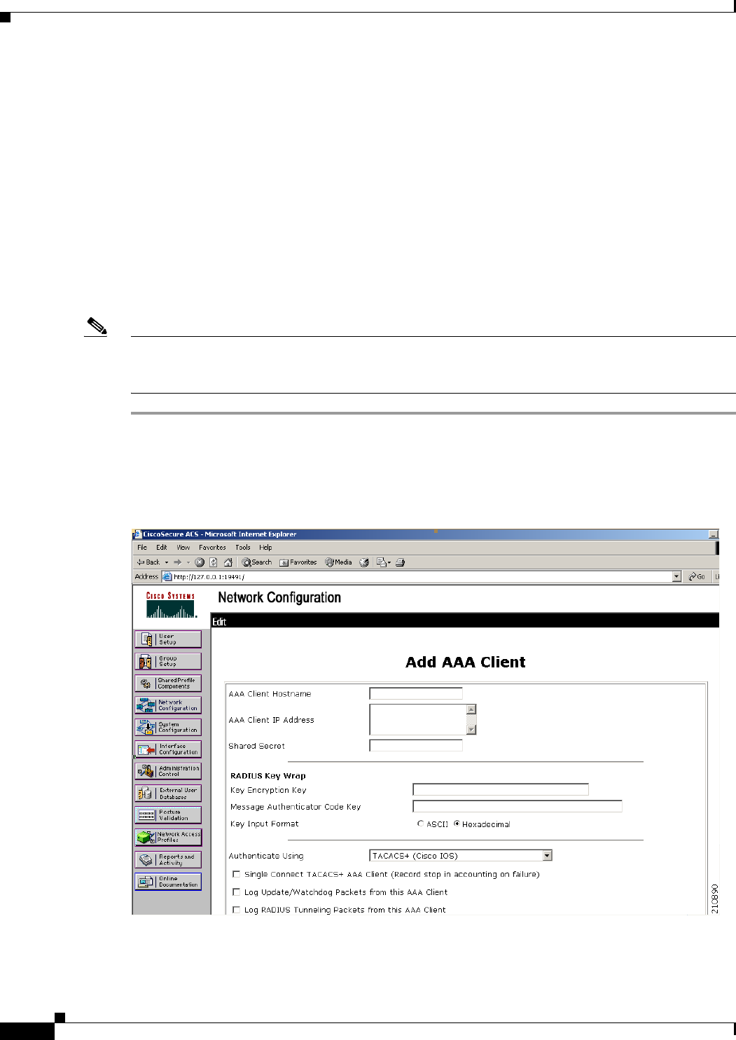
Step 2 Choose Add Entry under AAA Clients to add your controller to the server. The Add AAA Client page
appears (see Figure 6-1).
Figure 6-1 Add AAA Client Page on CiscoSecure ACS
Step 3 In the AAA Client Hostname text box, enter the name of your controller.

6-5
Cisco Wireless LAN Controller Configuration Guide
OL-21524-02
Chapter 6 Configuring Security Solutions
Configuring RADIUS
Step 4 In the AAA Client IP Address text box, enter the IP address of your controller.
Step 5 In the Shared Secret text box, enter the shared secret key to be used for authentication between the server
and the controller.
Note The shared secret key must be the same on both the server and the controller.
Step 6 From the Authenticate Using drop-down list, choose RADIUS (Cisco Aironet).
Step 7 Click Submit + Apply to save your changes.
Step 8 Choose Interface Configuration on the ACS main page.
Step 9 Choose RADIUS (Cisco Aironet). The RADIUS (Cisco Aironet) page appears.
Step 10 Under User Group, select the Cisco-Aironet-Session-Timeout check box.
Step 11 Click Submit to save your changes.
Step 12 On the ACS main page, from the left navigation pane, choose System Configuration.
Step 13 Choose Logging.
Step 14 When the Logging Configuration page appears, enable all of the events that you want to be logged and
save your changes.
Step 15 On the ACS main page, from the left navigation pane, choose Group Setup.

6-6
Cisco Wireless LAN Controller Configuration Guide
OL-21524-02
Chapter 6 Configuring Security Solutions
Configuring RADIUS
Step 16 Choose a previously created group from the Group drop-down list.
Note This step assumes that you have already assigned users to groups on the ACS according to the
roles to which they will be assigned.
Step 17 Click Edit Settings. The Group Setup page appears.
Step 18 Under Cisco Aironet Attributes, select the Cisco-Aironet-Session-Timeout check box and enter a
session timeout value in the edit box.
Step 19 Specify read-only or read-write access to controllers through RADIUS authentication, by setting the
Service-Type attribute (006) to Callback NAS Prompt for read-only access or to Administrative for
read-write privileges. If you do not set this attribute, the authentication process completes successfully
(without an authorization error on the controller), but you might be prompted to authenticate again.
Note If you set the Service-Type attribute on the ACS, make sure to select the Management check
box on the RADIUS Authentication Servers page of the controller GUI. See Step 17 in the next
section for more information.
Note The “RADIUS Authentication Attributes Sent by the Access Point” section on page 6-15 lists
the RADIUS attributes that are sent by a lightweight access point to a client in access-request
and access-accept packets.
Step 20 Click Submit to save your changes.
Using the GUI to Configure RADIUS
To configure RADIUS using the controller GUI, follow these steps:
Step 1 Choose Security > AAA > RADIUS.
Step 2 Perform one of the following:
• If you want to configure a RADIUS server for authentication, choose Authentication.
• If you want to configure a RADIUS server for accounting, choose Accounting.
Note The pages used to configure authentication and accounting contain mostly the same text boxes.
Therefore, these instructions walk through the configuration only once, using the Authentication
pages as examples. You would follow the same steps to configure multiple services and/or
multiple servers.
The RADIUS Authentication (or Accounting) Servers page appears (see Figure 6-2).

6-7
Cisco Wireless LAN Controller Configuration Guide
OL-21524-02
Chapter 6 Configuring Security Solutions
Configuring RADIUS
Figure 6-2 RADIUS Authentication Servers Page
This page lists any RADIUS servers that have already been configured.
• If you want to delete an existing server, hover your cursor over the blue drop-down arrow for that
server and choose Remove.
• If you want to make sure that the controller can reach a particular server, hover your cursor over the
blue drop-down arrow for that server and choose Ping.
Step 3 From the Call Station ID Type drop-down list, choose IP Address, System MAC Address, or AP MAC
Address to specify whether the IP address, system MAC address, or AP MAC address of the originator
will be sent to the RADIUS server in the Access-Request message.
Step 4 Enable RADIUS-to-controller key transport using AES key wrap protection by selecting the Use AES
Key Wrap check box. The default value is unselected. This feature is required for FIPS customers.
Step 5 Click Apply to commit your changes.
Step 6 Perform one of the following:
• To edit an existing RADIUS server, click the server index number for that server. The RADIUS
Authentication (or Accounting) Servers > Edit page appears.
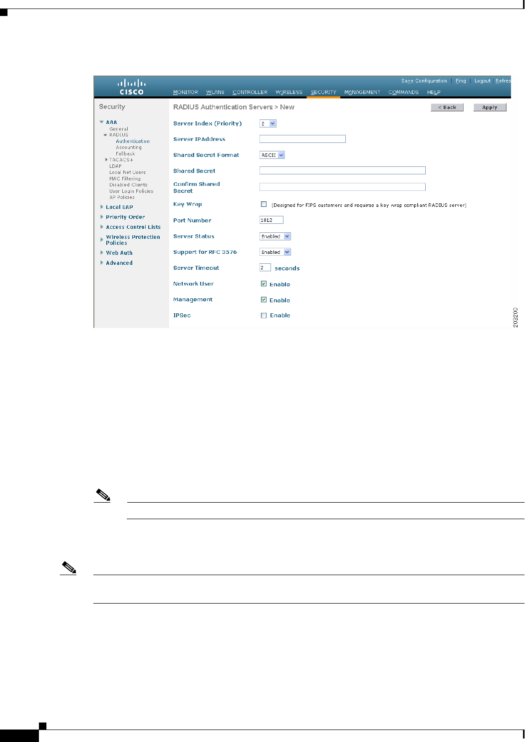
• To add a RADIUS server, click New. The RADIUS Authentication (or Accounting) Servers > New
page appears (see Figure 6-3).
6-8
Cisco Wireless LAN Controller Configuration Guide
OL-21524-02
Chapter 6 Configuring Security Solutions
Configuring RADIUS
Figure 6-3 RADIUS Authentication Servers > New Page
Step 7 If you are adding a new server, choose a number from the Server Index (Priority) drop-down list to
specify the priority order of this server in relation to any other configured RADIUS servers providing
the same service. You can configure up to 17 servers. If the controller cannot reach the first server, it
tries the second one in the list, then the third one if necessary, and so on.
Step 8 If you are adding a new server, enter the IP address of the RADIUS server in the Server IP Address text
box.
Step 9 From the Shared Secret Format drop-down list, choose ASCII or Hex to specify the format of the shared
secret key to be used between the controller and the RADIUS server. The default value is ASCII.
Step 10 In the Shared Secret and Confirm Shared Secret text boxes, enter the shared secret key to be used for
authentication between the controller and the server.
Note The shared secret key must be the same on both the server and the controller.
Step 11 If you are configuring a new RADIUS authentication server and want to enable AES key wrap, which
makes the shared secret between the controller and the RADIUS server more secure, follow these steps:
Note AES key wrap is designed for Federal Information Processing Standards (FIPS) customers and requires
a key-wrap compliant RADIUS authentication server.
a. Select the Key Wrap check box.
b. From the Key Wrap Format drop-down list, choose ASCII or HEX to specify the format of the AES
key wrap keys: Key Encryption Key (KEK) and Message Authentication Code Key (MACK).
c. In the Key Encryption Key (KEK) text box, enter the 16-byte KEK.
d. In the Message Authentication Code Key (MACK) text box, enter the 20-byte KEK.

6-9
Cisco Wireless LAN Controller Configuration Guide
OL-21524-02
Chapter 6 Configuring Security Solutions
Configuring RADIUS
Step 12 If you are adding a new server, enter the RADIUS server’s UDP port number for the interface protocols
in the Port Number text box. The valid range is 1 to 65535, and the default value is 1812 for
authentication and 1813 for accounting.
Step 13 From the Server Status text box, choose Enabled to enable this RADIUS server or choose Disabled to
disable it. The default value is Enabled.
Step 14 If you are configuring a new RADIUS authentication server, choose Enabled from the Support for RFC
3576 drop-down list to enable RFC 3576, which is an extension to the RADIUS protocol that allows
dynamic changes to a user session, or choose Disabled to disable this feature. The default value is
Enabled. RFC 3576 includes support for disconnecting users and changing authorizations applicable to
a user session and supports disconnect and change-of-authorization (CoA) messages. Disconnect
messages cause a user session to be terminated immediately where CoA messages modify session
authorization attributes such as data filters.
Step 15 In the Server Timeout text box, enter the number of seconds between retransmissions. The valid range
is 2 to 30 seconds, and the default value is 2 seconds.
Note We recommend that you increase the timeout value if you experience repeated reauthentication
attempts or the controller falls back to the backup server when the primary server is active and
reachable.
Step 16 Select the Network User check box to enable network user authentication (or accounting), or unselect
it to disable this feature. The default value is selected. If you enable this feature, this entry is considered
the RADIUS authentication (or accounting) server for network users. If you did not configure a RADIUS
server entry on the WLAN, you must enable this option for network users.
Step 17 If you are configuring a RADIUS authentication server, select the Management check box to enable
management authentication, or unselect it to disable this feature. The default value is selected. If you
enable this feature, this entry is considered the RADIUS authentication server for management users,
and authentication requests go to the RADIUS server.
Step 18 Select the IPSec check box to enable the IP security mechanism, or unselect it to disable this feature.
The default value is unselected.
Note The IPsec option appears only if a crypto card is installed in the controller.
Step 19 If you enabled IPsec in Step 18, follow these steps to configure additional IPsec parameters:
a. From the IPSec drop-down list, choose one of the following options as the authentication protocol
to be used for IP security: HMAC MD5 or HMAC SHA1. The default value is HMAC SHA1.
A message authentication code (MAC) is used between two parties that share a secret key to validate
information transmitted between them. HMAC (Hash MAC) is based on cryptographic hash
functions. It can be used in combination with any iterated cryptographic hash function. HMAC MD5
and HMAC SHA1 are two constructs of the HMAC using the MD5 hash function and the SHA1 hash
function. HMAC also uses a secret key for calculation and verification of the message authentication
values.
b. From the IPSec Encryption drop-down list, choose one of the following options to specify the IP
security encryption mechanism:
• DES—Data Encryption Standard that is a method of data encryption using a private (secret) key.
DES applies a 56-bit key to each 64-bit block of data.
• 3DES—Data Encryption Standard that applies three keys in succession. This is the default
value.
6-10
Cisco Wireless LAN Controller Configuration Guide
OL-21524-02
Chapter 6 Configuring Security Solutions
Configuring RADIUS
• AES CBS—Advanced Encryption Standard that uses keys with a length of 128, 192, or 256 bits
to encrypt data blocks with a length of 128, 192, or 256 bits. AES 128 CBC uses a 128-bit data
path in Cipher Clock Chaining (CBC) mode.
c. From the IKE Phase 1 drop-down list, choose one of the following options to specify the Internet
Key Exchange (IKE) protocol: Aggressive or Main. The default value is Aggressive.
IKE Phase 1 is used to negotiate how IKE should be protected. Aggressive mode passes more
information in fewer packets with the benefit of slightly faster connection establishment at the cost
of transmitting the identities of the security gateways in the clear.
d. In the Lifetime text box, enter a value (in seconds) to specify the timeout interval for the session.
The valid range is 1800 to 57600 seconds, and the default value is 1800 seconds.
e. From the IKE Diffie Hellman Group drop-down list, choose one of the following options to specify
the IKE Diffie Hellman group: Group 1 (768 bits), Group 2 (1024 bits), or Group 5 (1536 bits).
The default value is Group 1 (768 bits).
Diffie-Hellman techniques are used by two devices to generate a symmetric key through which they
can publicly exchange values and generate the same symmetric key. Although all three groups
provide security from conventional attacks, Group 5 is considered more secure because of its larger
key size. However, computations involving Group 1 and Group 2 based keys might occur slightly
faster because of their smaller prime number size.
Step 20 Click Apply to commit your changes.
Step 21 Click Save Configuration to save your changes.
Step 22 Repeat the previous steps if you want to configure any additional services on the same server or any
additional RADIUS servers.
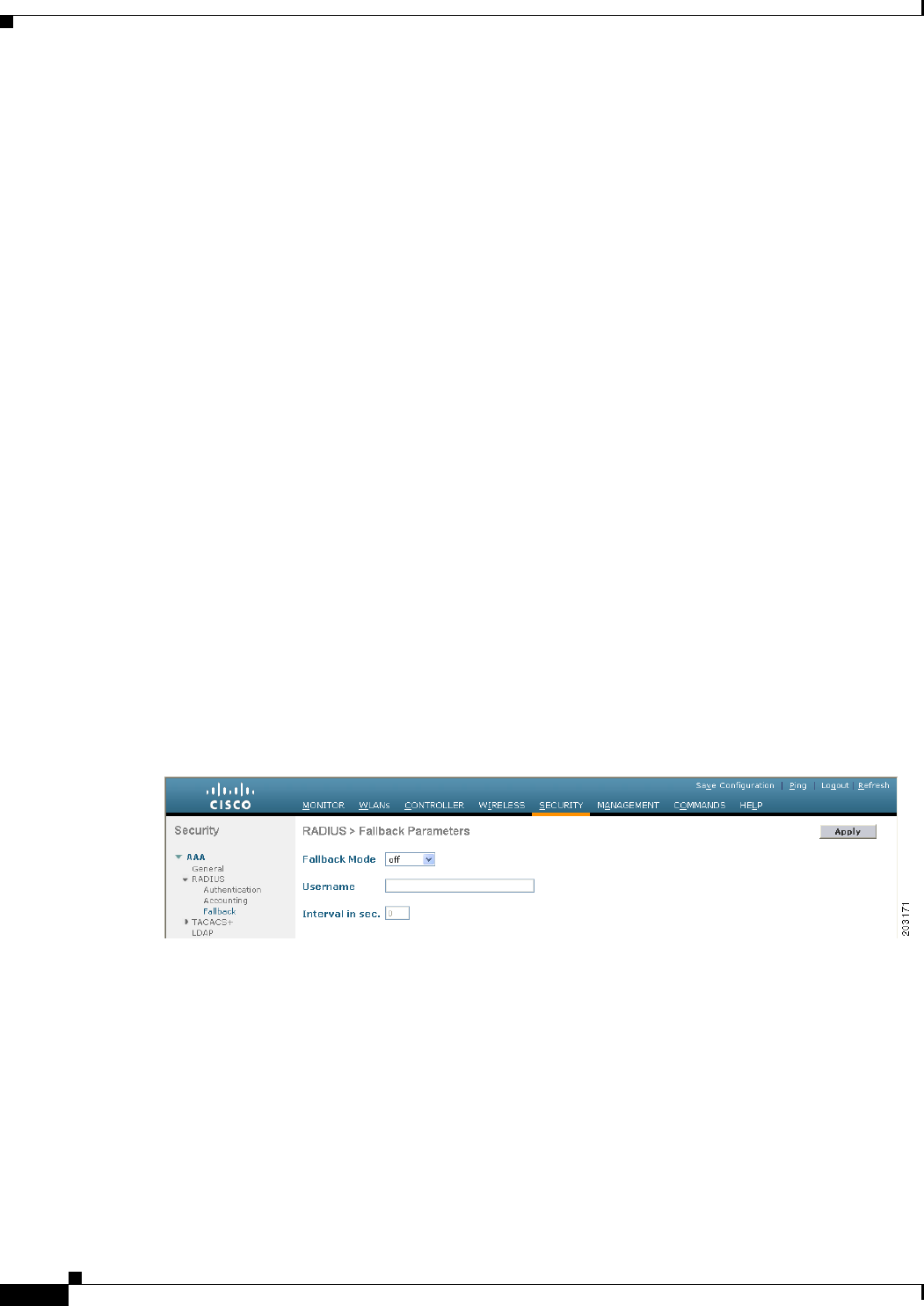
Step 23 Specify the RADIUS server fallback behavior, as follows:
a. Choose Security > AAA > RADIUS > Fallback to open the RADIUS > Fallback Parameters page
(see Figure 6-4).
Figure 6-4 RADIUS > Fallback Parameters Page
b. From the Fallback Mode drop-down list, choose one of the following options:
• Off—Disables RADIUS server fallback. This is the default value.
• Passive—Causes the controller to revert to a server with a lower priority from the available
backup servers without using extraneous probe messages. The controller ignores all inactive
servers for a time period and retries later when a RADIUS message needs to be sent.
• Active—Causes the controller to revert to a server with a lower priority from the available
backup servers by using RADIUS probe messages to proactively determine whether a server
that has been marked inactive is back online. The controller ignores all inactive servers for all
6-11
Cisco Wireless LAN Controller Configuration Guide
OL-21524-02
Chapter 6 Configuring Security Solutions
Configuring RADIUS
active RADIUS requests. Once the primary server receives a response from the recovered ACS
server, the active fallback RADIUS server no longer sends probe messages to the server
requesting the active probe authentication.
c. If you enabled Active fallback mode in Step b, enter the name to be sent in the inactive server probes
in the Username text box. You can enter up to 16 alphanumeric characters. The default value is
“cisco-probe.”
d. If you enabled Active fallback mode in Step b, enter the probe interval value (in seconds) in the
Interval in Sec text box. The interval serves as inactive time in passive mode and probe interval in
active mode. The valid range is 180 to 3600 seconds, and the default value is 300 seconds.
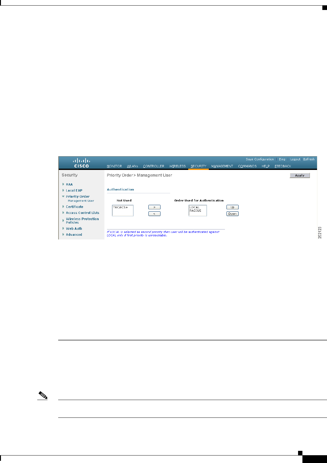
Step 24 Specify the order of authentication when multiple databases are configured by choosing Security >
Priority Order > Management User. The Priority Order > Management User page appears (see
Figure 6-5).
Figure 6-5 Priority Order > Management User Page
Step 25 In the Order Used for Authentication text box, specify which servers have priority when the controller
attempts to authenticate management users. Use the > and < buttons to move servers between the Not
Used and Order Used for Authentication text boxes. After the desired servers appear in the Order Used
for Authentication text box, use the Up and Down buttons to move the priority server to the top of the
list.
By default, the local database is always queried first. If the username is not found, the controller switches
to the RADIUS server if configured for RADIUS or to the TACACS+ server if configured for TACACS+.
The default setting is local and then RADIUS.
Step 26 Click Apply to commit your changes.
Step 27 Click Save Configuration to save your changes.
Using the CLI to Configure RADIUS
To configure RADIUS using the controller CLI, follow these steps:
Note See the “Using the GUI to Configure RADIUS” section on page 6-6 for the valid ranges and default
values of the parameters used in the CLI commands.

6-12
Cisco Wireless LAN Controller Configuration Guide
OL-21524-02
Chapter 6 Configuring Security Solutions
Configuring RADIUS
Step 1 Specify whether the IP address, system MAC address, or AP MAC address of the originator will be sent
to the RADIUS server in the Access-Request message by entering this command:
config radius callStationIdType {ip_address, mac_address, ap_mac_address, ap_macaddr_ssid}
Step 2 Specify the delimiter to be used in the MAC addresses that are sent to the RADIUS authentication or
accounting server in Access-Request messages by entering this command:
config radius {auth | acct} mac-delimiter {colon | hyphen | single-hyphen | none}
where
• colon sets the delimiter to a colon (the format is xx:xx:xx:xx:xx:xx).
• hyphen sets the delimiter to a hyphen (the format is xx-xx-xx-xx-xx-xx). This is the default value.
• single-hyphen sets the delimiter to a single hyphen (the format is xxxxxx-xxxxxx).
• none disables delimiters (the format is xxxxxxxxxxxx).
Step 3 Configure a RADIUS authentication server by entering these commands:
• config radius auth add index server_ip_address port# {ascii | hex} shared_secret—Adds a
RADIUS authentication server.
• config radius auth keywrap {enable | disable}—Enables AES key wrap, which makes the shared
secret between the controller and the RADIUS server more secure. AES key wrap is designed for
Federal Information Processing Standards (FIPS) customers and requires a key-wrap compliant
RADIUS authentication server.
• config radius auth keywrap add {ascii | hex} kek mack index—Configures the AES key wrap
attributes
where
–
kek specifies the 16-byte Key Encryption Key (KEK).
–
mack specifies the 20-byte Message Authentication Code Key (MACK).
–
index specifies the index of the RADIUS authentication server on which to configure the AES
key wrap.
• config radius auth rfc3576 {enable | disable} index—Enables or disables RFC 3576, which is an
extension to the RADIUS protocol that allows dynamic changes to a user session. RFC 3576
includes support for disconnecting users and changing authorizations applicable to a user session
and supports disconnect and change-of-authorization (CoA) messages. Disconnect messages cause
a user session to be terminated immediately where CoA messages modify session authorization
attributes such as data filters.
• config radius auth retransmit-timeout index timeout—Configures the retransmission timeout
value for a RADIUS authentication server.
• config radius auth network index {enable | disable}—Enables or disables network user
authentication. If you enable this feature, this entry is considered the RADIUS authentication server
for network users. If you did not configure a RADIUS server entry on the WLAN, you must enable
this option for network users.
• config radius auth management index {enable | disable}—Enables or disables management
authentication. If you enable this feature, this entry is considered the RADIUS authentication server
for management users, and authentication requests go to the RADIUS server.
• config radius auth ipsec {enable | disable} index—Enables or disables the IP security mechanism.
• config radius auth ipsec authentication {hmac-md5 | hmac-sha1} index—Configures the
authentication protocol to be used for IP security.

6-13
Cisco Wireless LAN Controller Configuration Guide
OL-21524-02
Chapter 6 Configuring Security Solutions
Configuring RADIUS
• config radius auth ipsec encryption {3des | aes | des | none} index—Configures the IP security
encryption mechanism.
• config radius auth ipsec ike dh-group {group-1 | group-2 | group-5} index—Configures the IKE
Diffie Hellman group.
• config radius auth ipsec ike lifetime interval index—Configures the timeout interval for the
session.
• config radius auth ipsec ike phase1{aggressive | main} index—Configures the Internet Key
Exchange (IKE) protocol.
• config radius auth {enable | disable} index—Enables or disables a RADIUS authentication server.
• config radius auth delete index—Deletes a previously added RADIUS authentication server.
Step 4 Configure a RADIUS accounting server by entering these commands:
• config radius acct add index server_ip_address port# {ascii | hex} shared_secret—Adds a
RADIUS accounting server.
• config radius acct server-timeout index timeout—Configures the retransmission timeout value for
a RADIUS accounting server.
• config radius acct network index {enable | disable}—Enables or disables network user
accounting. If you enable this feature, this entry is considered the RADIUS accounting server for
network users. If you did not configure a RADIUS server entry on the WLAN, you must enable this
option for network users.
• config radius acct ipsec {enable | disable} index—Enables or disables the IP security mechanism.
• config radius acct ipsec authentication {hmac-md5 | hmac-sha1} index—Configures the
authentication protocol to be used for IP security.
• config radius acct ipsec encryption {3des | aes | des | none} index—Configures the IP security
encryption mechanism.
• config radius acct ipsec ike dh-group {group-1 | group-2 | group-5} index—Configures the IKE
Diffie Hellman group.
• config radius acct ipsec ike lifetime interval index—Configures the timeout interval for the
session.
• config radius acct ipsec ike phase1{aggressive | main} index—Configures the Internet Key
Exchange (IKE) protocol.
• config radius acct {enable | disable} index—Enables or disables a RADIUS accounting server.
• config radius acct delete index—Deletes a previously added RADIUS accounting server.
Step 5 Configure the RADIUS server fallback behavior by entering this command:
config radius fallback-test mode {off | passive | active}
where
• off disables RADIUS server fallback.
• passive causes the controller to revert to a server with a lower priority from the available backup
servers without using extraneous probe messages. The controller simply ignores all inactive servers
for a time period and retries later when a RADIUS message needs to be sent.
• active causes the controller to revert to a server with a lower priority from the available backup
servers by using RADIUS probe messages to proactively determine whether a server that has been
marked inactive is back online. The controller simply ignores all inactive servers for all active

6-14
Cisco Wireless LAN Controller Configuration Guide
OL-21524-02
Chapter 6 Configuring Security Solutions
Configuring RADIUS
RADIUS requests. Once the primary server receives a response from the recovered ACS server, the
active fallback RADIUS server no longer sends probe messages to the server requesting the active
probe authentication.
Step 6 If you enabled Active mode in Step 5, enter these commands to configure additional fallback parameters:
• config radius fallback-test username username—Specifies the name to be sent in the inactive
server probes. You can enter up to 16 alphanumeric characters for the username parameter.
• config radius fallback-test interval interval—Specifies the probe interval value (in seconds).
Step 7 Save your changes by entering this command:
save config
Step 8 Configure the order of authentication when multiple databases are configured by entering this command:
config aaa auth mgmt AAA_server_type AAA_server_type
where AAA_server_type is local, radius, or tacacs.
To see the current management authentication server order, enter this command:
show aaa auth
Information similar to the following appears:
Management authentication server order:
1......................................... local
2...................................... radius
Step 9 See RADIUS statistics by entering these commands:
• show radius summary—Shows a summary of RADIUS servers and statistics.
• show radius auth statistics—Shows the RADIUS authentication server statistics.
• show radius acct statistics—Shows the RADIUS accounting server statistics.
• show radius rfc3576 statistics—Shows a summary of the RADIUS RFC-3576 server.
Information similar to the following appears for the show radius auth statistics command:
Authentication Servers:
Server Index..................................... 1
Server Address................................... 10.91.104.76
Msg Round Trip Time.............................. 0 (msec)
First Requests................................... 1
Retry Requests................................... 0
Accept Responses................................. 0
Reject Responses................................. 0
Challenge Responses.............................. 0
Malformed Msgs................................... 0
Bad Authenticator Msgs........................... 0
Pending Requests................................. 0
Timeout Requests................................. 0
Unknowntype Msgs................................. 0
Other Drops................................... 0
Information similar to the following appears for the show radius acct statistics command:
Accounting Servers:
Server Index..................................... 1
Server Address................................... 10.10.10.1
Msg Round Trip Time.............................. 0 (msec)
First Requests................................... 1
Retry Requests................................... 0

6-15
Cisco Wireless LAN Controller Configuration Guide
OL-21524-02
Chapter 6 Configuring Security Solutions
Configuring RADIUS
Accounting Responses............................. 0
Malformed Msgs................................... 0
Bad Authenticator Msgs........................... 0
Pending Requests................................. 0
Timeout Requests................................. 0
Unknowntype Msgs................................. 0
Other Drops...................................... 0
Information similar to the following appears for the show radius rfc3576 statistics command:
RFC-3576 Servers:
Server Index..................................... 1
Server Address................................... 10.91.104.76
Disconnect-Requests.............................. 0
COA-Requests..................................... 0
Retransmitted Requests........................... 0
Malformed Requests............................... 0
Bad Authenticator Requests....................... 0
Other Drops...................................... 0
Sent Disconnect-Ack.............................. 0
Sent Disconnect-Nak.............................. 0
Sent CoA-Ack..................................... 0
Sent CoA-Nak.................................. 0
Step 10 See active security associations by entering these commands:
• show ike {brief | detailed} ip_or_mac_addr—Shows a brief or detailed summary of active IKE
security associations.
• show ipsec {brief | detailed} ip_or_mac_addr—Shows a brief or detailed summary of active IPSec
security associations.
Step 11 Clear the statistics for one or more RADIUS servers by entering this command:
clear stats radius {auth | acct} {index | all}
Step 12 Make sure that the controller can reach the RADIUS server by entering this command:
ping server_ip_address
RADIUS Authentication Attributes Sent by the Access Point
Table 6-1 through Table 6-5 identify the RADIUS authentication attributes sent by a lightweight access
point to a client in access-request and access-accept packets.
Ta b l e 6-1 Authentication Attributes Sent in Access-Request Packets
Attribute ID Description
1User-Name
2Password
3CHAP-Password
4NAS-IP-Address
5NAS-Port
6Service-Type1

6-16
Cisco Wireless LAN Controller Configuration Guide
OL-21524-02
Chapter 6 Configuring Security Solutions
Configuring RADIUS
Note These Cisco-specific attributes are not supported: Auth-Algo-Type and SSID.
12 Framed-MTU
30 Called-Station-ID (MAC address)
31 Calling-Station-ID (MAC address)
32 NAS-Identifier
33 Proxy-State
60 CHAP-Challenge
61 NAS-Port-Type
79 EAP-Message
243 TPLUS-Role
1. To specify read-only or read-write access to controllers through RADIUS authentication, you must set the
Service-Type attribute (6) on the RADIUS server to Callback NAS Prompt for read-only access or to
Administrative for read-write privileges. See Step 19 in the “Configuring RADIUS on the ACS” section for
more information.
Ta b l e 6-2 Authentication Attributes Honored in Access-Accept Packets (Cisco)
Attribute ID Description
1Cisco-LEAP-Session-Key
2Cisco-Keywrap-Msg-Auth-Code
3Cisco-Keywrap-NonCE
4Cisco-Keywrap-Key
5Cisco-URL-Redirect
6Cisco-URL-Redirect-ACL
Table 6-1 Authentication Attributes Sent in Access-Request Packets
Attribute ID Description

6-17
Cisco Wireless LAN Controller Configuration Guide
OL-21524-02
Chapter 6 Configuring Security Solutions
Configuring RADIUS
Note Message authentication is not supported.
Ta b l e 6-3 Authentication Attributes Honored in Access-Accept Packets (Standard)
Attribute ID Description
6Service-Type1
8Framed-IP-Address
25 Class
26 Vendor-Specific
27 Timeout
29 Termination-Action
40 Acct-Status-Type
64 Tunnel-Type
79 EAP-Message
81 Tunnel-Group-ID
1. To specify read-only or read-write access to controllers through RADIUS authentication, you must set the
Service-Type attribute (6) on the RADIUS server to Callback NAS Prompt for read-only access or to
Administrative for read-write privileges. See Step 19 in the “Configuring RADIUS on the ACS” section for
more information.
Ta b l e 6-4 Authentication Attributes Honored in Access-Accept Packets (Microsoft)
Attribute ID Description
11 MS-CHAP-Challenge
16 MS-MPPE-Send-Key
17 MS-MPPE-Receive-Key
25 MS-MSCHAP2-Response
26 MS-MSCHAP2-Success

6-18
Cisco Wireless LAN Controller Configuration Guide
OL-21524-02
Chapter 6 Configuring Security Solutions
Configuring RADIUS
RADIUS Accounting Attributes
Table 6-6 identifies the RADIUS accounting attributes for accounting requests sent from a controller to
the RADIUS server. Table 6-7 lists the different values for the Accounting-Status-Type attribute (40).
Ta b l e 6-5 Authentication Attributes Honored in Access-Accept Packets (Airespace)
Attribute ID Description
1VAP-ID
2QoS-Level
3DSCP
48021P-Type
5VLAN-Interface-Name
6ACL-Name
7Data-Bandwidth-Average-Contract
8Real-Time-Bandwidth-Average-Contract
9Data-Bandwidth-Burst-Contract
10 Real-Time-Bandwidth-Burst-Contract
11 Guest-Role-Name
Ta b l e 6-6 Accounting Attributes for Accounting Requests
Attribute ID Description
1User-Name
4NAS-IP-Address
5NAS-Port
8Framed-IP-Address
25 Class
30 Called-Station-ID (MAC address)
31 Calling-Station-ID (MAC address)
32 NAS-Identifier
40 Accounting-Status-Type
41 Accounting-Delay-Time (Stop and interim messages only)
42 Accounting-Input-Octets (Stop and interim messages only)
43 Accounting-Output-Octets (Stop and interim messages only)
44 Accounting-Session-ID
45 Accounting-Authentic
46 Accounting-Session-Time (Stop and interim messages only)
47 Accounting-Input-Packets (Stop and interim messages only)
48 Accounting-Output-Packets (Stop and interim messages only)
49 Accounting-Terminate-Cause (Stop messages only)

6-19
Cisco Wireless LAN Controller Configuration Guide
OL-21524-02
Chapter 6 Configuring Security Solutions
Configuring TACACS+
Configuring TACACS+
Terminal Access Controller Access Control System Plus (TACACS+) is a client/server protocol that
provides centralized security for users attempting to gain management access to a controller. It serves as
a backend database similar to local and RADIUS. However, local and RADIUS provide only
authentication support and limited authorization support while TACACS+ provides three services:
• Authentication—The process of verifying users when they attempt to log into the controller.
Users must enter a valid username and password in order for the controller to authenticate users to
the TACACS+ server. The authentication and authorization services are tied to one another. For
example, if authentication is performed using the local or RADIUS database, then authorization
would use the permissions associated with the user in the local or RADIUS database (which are
read-only, read-write, and lobby-admin) and not use TACACS+. Similarly, when authentication is
performed using TACACS+, authorization is tied to TACACS+.
Note When multiple databases are configured, you can use the controller GUI or CLI to specify
the sequence in which the backend databases should be tried.
• Authorization—The process of determining the actions that users are allowed to take on the
controller based on their level of access.
For TACACS+, authorization is based on privilege (or role) rather than specific actions. The
available roles correspond to the seven menu options on the controller GUI: MONITOR, WLAN,
CONTROLLER, WIRELESS, SECURITY, MANAGEMENT, and COMMANDS. An additional
role, LOBBY, is available for users who require only lobby ambassador privileges. The roles to
which users are assigned are configured on the TACACS+ server. Users can be authorized for one
or more roles. The minimum authorization is MONITOR only, and the maximum is ALL, which
authorizes the user to execute the functionality associated with all seven menu options. For example,
a user who is assigned the role of SECURITY can make changes to any items appearing on the
64 Tunnel-Type
65 Tunnel-Medium-Type
81 Tunnel-Group-ID
Ta b l e 6-7 Accounting-Status-Type Attribute Values
Attribute ID Description
1Start
2Stop
3Interim-Update
7Accounting-On
8Accounting-Off
9-14 Reserved for Tunneling Accounting
15 Reserved for Failed
Table 6-6 Accounting Attributes for Accounting Requests (continued)
Attribute ID Description

6-20
Cisco Wireless LAN Controller Configuration Guide
OL-21524-02
Chapter 6 Configuring Security Solutions
Configuring TACACS+
Security menu (or designated as security commands in the case of the CLI). If users are not
authorized for a particular role (such as WLAN), they can still access that menu option in read-only
mode (or the associated CLI show commands). If the TACACS+ authorization server becomes
unreachable or unable to authorize, users are unable to log into the controller.
Note If users attempt to make changes on a controller GUI page that are not permitted for their
assigned role, a message appears indicating that they do not have sufficient privilege. If users
enter a controller CLI command that is not permitted for their assigned role, a message may
appear indicating that the command was successfully executed although it was not. In this
case, the following additional message appears to inform users that they lack sufficient
privileges to successfully execute the command: “Insufficient Privilege! Cannot execute
command!”
• Accounting—The process of recording user actions and changes.
Whenever a user successfully executes an action, the TACACS+ accounting server logs the changed
attributes, the user ID of the person who made the change, the remote host where the user is logged
in, the date and time when the command was executed, the authorization level of the user, and a
description of the action performed and the values provided. If the TACACS+ accounting server
becomes unreachable, users are able to continue their sessions uninterrupted.
TACACS+ uses Transmission Control Protocol (TCP) for its transport, unlike RADIUS which uses User
Datagram Protocol (UDP). It maintains a database and listens on TCP port 49 for incoming requests. The
controller, which requires access control, acts as the client and requests AAA services from the server.
The traffic between the controller and the server is encrypted by an algorithm defined in the protocol and
a shared secret key configured on both devices.
You can configure up to three TACACS+ authentication, authorization, and accounting servers each. For
example, you may want to have one central TACACS+ authentication server but several TACACS+
authorization servers in different regions. If you configure multiple servers of the same type and the first
one fails or becomes unreachable, the controller automatically tries the second one and then the third
one if necessary.
Note If multiple TACACS+ servers are configured for redundancy, the user database must be identical in all
the servers for the backup to work properly.
You must configure TACACS+ on both your CiscoSecure Access Control Server (ACS) and your
controller. You can configure the controller through either the GUI or the CLI.
Configuring TACACS+ on the ACS
To configure TACACS+ on the ACS, follow these steps:
Note TACACS+ is supported on CiscoSecure ACS version 3.2 and later releases. The figures and instructions
in this section pertain to ACS version 4.1 and may vary for other versions. See the CiscoSecure ACS
documentation for the version that you are running.
Step 1 Choose Network Configuration on the ACS main page.
6-21
Cisco Wireless LAN Controller Configuration Guide
OL-21524-02
Chapter 6 Configuring Security Solutions
Configuring TACACS+
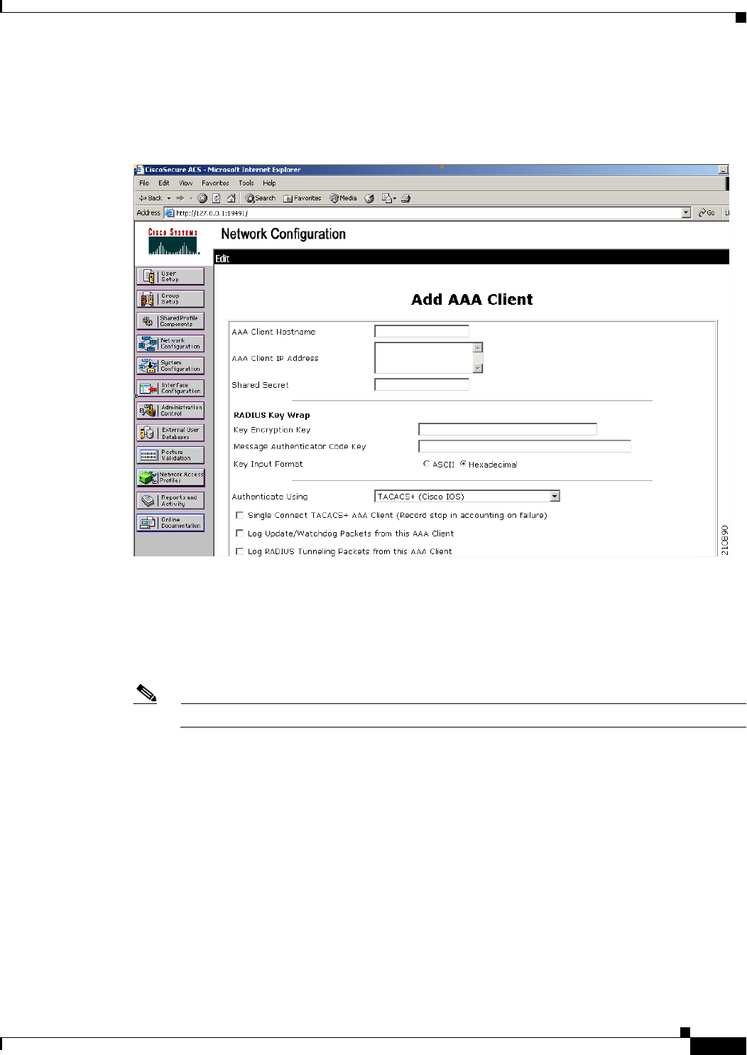
Step 2 Choose Add Entry under AAA Clients to add your controller to the server. The Add AAA Client page
appears (see Figure 6-6).
Figure 6-6 Add AAA Client Page on CiscoSecure ACS
Step 3 In the AAA Client Hostname text box, enter the name of your controller.
Step 4 In the AAA Client IP Address text box, enter the IP address of your controller.
Step 5 In the Shared Secret text box, enter the shared secret key to be used for authentication between the server
and the controller.
Note The shared secret key must be the same on both the server and the controller.
Step 6 From the Authenticate Using drop-down list, choose TACACS+ (Cisco IOS).
Step 7 Click Submit + Apply to save your changes.
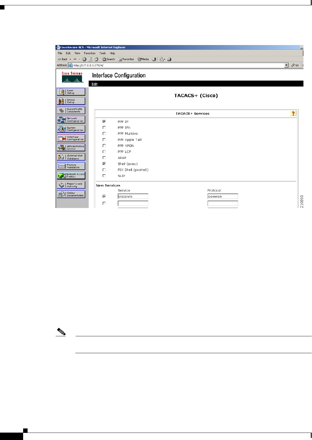
Step 8 On the ACS main page, in the left navigation pane, choose Interface Configuration.
Step 9 Choose TACACS+ (Cisco IOS). The TACACS+ (Cisco) page appears (see Figure 6-7).
6-22
Cisco Wireless LAN Controller Configuration Guide
OL-21524-02
Chapter 6 Configuring Security Solutions
Configuring TACACS+
Figure 6-7 TACACS+ (Cisco) Page on CiscoSecure ACS
Step 10 Under TACACS+ Services, select the Shell (exec) check box.
Step 11 Under New Services, select the first check box and enter ciscowlc in the Service text box and common
in the Protocol text box.
Step 12 Under Advanced Configuration Options, select the Advanced TACACS+ Features check box.
Step 13 Click Submit to save your changes.
Step 14 On the ACS main page, in the left navigation pane, choose System Configuration.
Step 15 Choose Logging.
Step 16 When the Logging Configuration page appears, enable all of the events that you want to be logged and
save your changes.
Step 17 On the ACS main page, in the left navigation pane, choose Group Setup.
Step 18 From the Group drop-down list, choose a previously created group.
Note This step assumes that you have already assigned users to groups on the ACS according to the
roles to which they will be assigned.
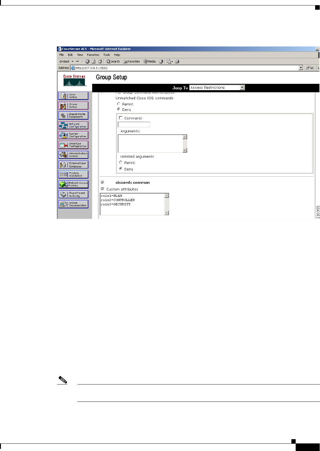
Step 19 Click Edit Settings. The Group Setup page appears (see Figure 6-8).
6-23
Cisco Wireless LAN Controller Configuration Guide
OL-21524-02
Chapter 6 Configuring Security Solutions
Configuring TACACS+
Figure 6-8 Group Setup Page on CiscoSecure ACS
Step 20 Under TACACS+ Settings, select the ciscowlc common check box.
Step 21 Select the Custom Attributes check box.
Step 22 In the text box below Custom Attributes, specify the roles that you want to assign to this group. The
available roles are MONITOR, WLAN, CONTROLLER, WIRELESS, SECURITY, MANAGEMENT,
COMMANDS, ALL, and LOBBY. The first seven correspond to the menu options on the controller GUI
and allow access to those particular controller features. You can enter one or multiple roles, depending
on the group’s needs. Use ALL to specify all seven roles or LOBBY to specify the lobby ambassador
role. Enter the roles using this format:
rolex=ROLE
For example, to specify the WLAN, CONTROLLER, and SECURITY roles for a particular user group,
you would enter the following text:
role1=WLAN
role2=CONTROLLER
role3=SECURITY
To give a user group access to all seven roles, you would enter the following text:
role1=ALL
Note Make sure to enter the roles using the format shown above. The roles must be in all uppercase
letters, and there can be no spaces within the text.
6-24
Cisco Wireless LAN Controller Configuration Guide
OL-21524-02
Chapter 6 Configuring Security Solutions
Configuring TACACS+
Note You should not combine the MONITOR role or the LOBBY role with any other roles. If you
specify one of these two roles in the Custom Attributes text box, users will have MONITOR or
LOBBY privileges only, even if additional roles are specified.
Step 23 Click Submit to save your changes.
Using the GUI to Configure TACACS+
To configure TACACS+ using the controller GUI, follow these steps:
Step 1 Choose Security > AAA > TACACS+.
Step 2 Perform one of the following:
• If you want to configure a TACACS+ server for authentication, choose Authentication.
• If you want to configure a TACACS+ server for authorization, choose Authorization.
• If you want to configure a TACACS+ server for accounting, choose Accounting.
Note The pages used to configure authentication, authorization, and accounting all contain the same
text boxes. Therefore, these instructions walk through the configuration only once, using the
Authentication pages as examples. You would follow the same steps to configure multiple
services and/or multiple servers.
Note For basic management authentication via TACACS+ to succeed, it is required to configure
authentication and authorization servers on the WLC. Accounting configuration is optional.
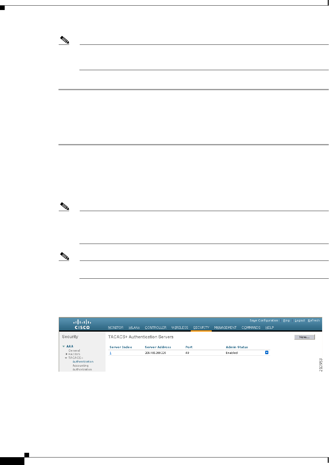
The TACACS+ (Authentication, Authorization, or Accounting) Servers page appears (see Figure 6-9).
Figure 6-9 TACACS+ Authentication Servers Page
This page lists any TACACS+ servers that have already been configured.
• If you want to delete an existing server, hover your cursor over the blue drop-down arrow for that
server and choose Remove.
• If you want to make sure that the controller can reach a particular server, hover your cursor over the
blue drop-down arrow for that server and choose Ping.
6-25
Cisco Wireless LAN Controller Configuration Guide
OL-21524-02
Chapter 6 Configuring Security Solutions
Configuring TACACS+
Step 3 Perform one of the following:
• To edit an existing TACACS+ server, click the server index number for that server. The TACACS+
(Authentication, Authorization, or Accounting) Servers > Edit page appears.
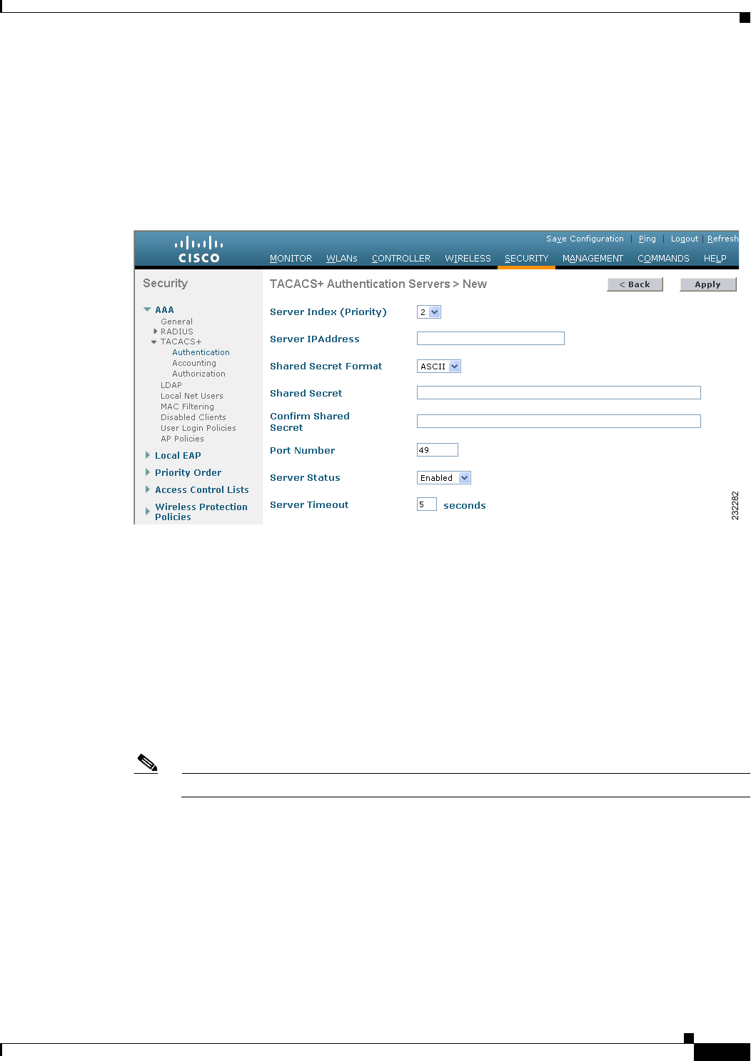
• To add a TACACS+ server, click New. The TACACS+ (Authentication, Authorization, or
Accounting) Servers > New page appears (see Figure 6-10).
Figure 6-10 TACACS+ Authentication Servers > New Page
Step 4 If you are adding a new server, choose a number from the Server Index (Priority) drop-down list to
specify the priority order of this server in relation to any other configured TACACS+ servers providing
the same service. You can configure up to three servers. If the controller cannot reach the first server, it
tries the second one in the list and then the third if necessary.
Step 5 If you are adding a new server, enter the IP address of the TACACS+ server in the Server IP Address text
box.
Step 6 From the Shared Secret Format drop-down list, choose ASCII or Hex to specify the format of the shared
secret key to be used between the controller and the TACACS+ server. The default value is ASCII.
Step 7 In the Shared Secret and Confirm Shared Secret text boxes, enter the shared secret key to be used for
authentication between the controller and the server.
Note The shared secret key must be the same on both the server and the controller.
Step 8 If you are adding a new server, enter the TACACS+ server’s TCP port number for the interface protocols
in the Port Number text box. The valid range is 1 to 65535, and the default value is 49.
Step 9 In the Server Status text box, choose Enabled to enable this TACACS+ server or choose Disabled to
disable it. The default value is Enabled.
6-26
Cisco Wireless LAN Controller Configuration Guide
OL-21524-02
Chapter 6 Configuring Security Solutions
Configuring TACACS+
Step 10 In the Server Timeout text box, enter the number of seconds between retransmissions. The valid range
is 5 to 30 seconds, and the default value is 5 seconds.
Note We recommend that you increase the timeout value if you experience repeated reauthentication
attempts or the controller falls back to the backup server when the primary server is active and
reachable.
Step 11 Click Apply to commit your changes.
Step 12 Click Save Configuration to save your changes.
Step 13 Repeat the previous steps if you want to configure any additional services on the same server or any
additional TACACS+ servers.
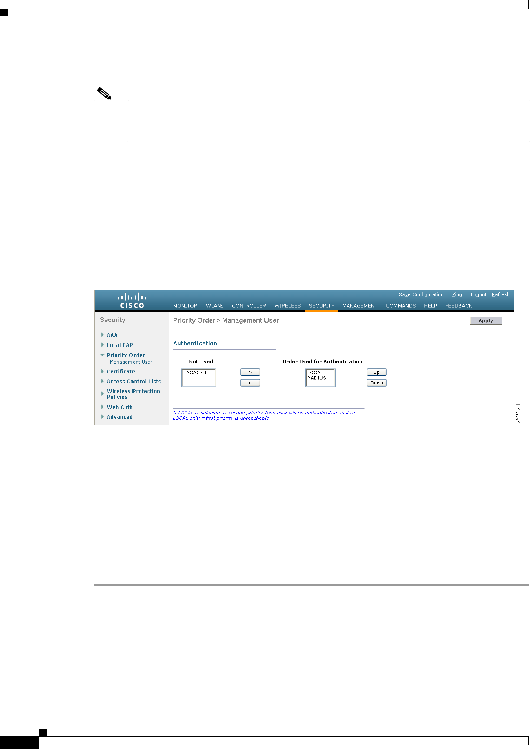
Step 14 Specify the order of authentication when multiple databases are configured by choosing Security >
Priority Order > Management User. The Priority Order > Management User page appears (see
Figure 6-11).
Figure 6-11 Priority Order > Management User Page
Step 15 In the Order Used for Authentication text box, specify which servers have priority when the controller
attempts to authenticate management users. Use the > and < buttons to move servers between the Not
Used and Order Used for Authentication text boxes. After the desired servers appear in the Order Used
for Authentication text box, use the Up and Down buttons to move the priority server to the top of the
list.
By default, the local database is always queried first. If the username is not found, the controller switches
to the RADIUS server if configured for RADIUS or to the TACACS+ server if configured for TACACS+.
The default setting is local and then RADIUS.
Step 16 Click Apply to commit your changes.
Step 17 Click Save Configuration to save your changes.
Using the CLI to Configure TACACS+
To configure TACACS+ using the controller CLI, use these commands:

6-27
Cisco Wireless LAN Controller Configuration Guide
OL-21524-02
Chapter 6 Configuring Security Solutions
Configuring TACACS+
Note See the “Using the GUI to Configure TACACS+” section on page 6-24 for the valid ranges and default
values of the parameters used in the CLI commands.
• Configure a TACACS+ authentication server by entering these commands:
–
config tacacs auth add index server_ip_address port# {ascii | hex} shared_secret—Adds a
TACACS+ authentication server.
–
config tacacs auth delete index—Deletes a previously added TACACS+ authentication server.
–
config tacacs auth (enable | disable} index—Enables or disables a TACACS+ authentication
server.
–
config tacacs auth server-timeout index timeout—Configures the retransmission timeout
value for a TACACS+ authentication server.
• Configure a TACACS+ authorization server by entering these commands:
• config tacacs athr add index server_ip_address port# {ascii | hex} shared_secret—Adds a
TACACS+ authorization server.
• config tacacs athr delete index—Deletes a previously added TACACS+ authorization server.
• config tacacs athr (enable | disable} index—Enables or disables a TACACS+ authorization
server.
• config tacacs athr server-timeout index timeout—Configures the retransmission timeout value
for a TACACS+ authorization server.
• Configure a TACACS+ accounting server by entering these commands:
• config tacacs acct add index server_ip_address port# {ascii | hex} shared_secret—Adds a
TACACS+ accounting server.
• config tacacs acct delete index—Deletes a previously added TACACS+ accounting server.
• config tacacs acct (enable | disable} index—Enables or disables a TACACS+ accounting
server.
• config tacacs acct server-timeout index timeout—Configures the retransmission timeout value
for a TACACS+ accounting server.
• See TACACS+ statistics by entering these commands:
• show tacacs summary—Shows a summary of TACACS+ servers and statistics.
• show tacacs auth stats—Shows the TACACS+ authentication server statistics.
• show tacacs athr stats—Shows the TACACS+ authorization server statistics.
• show tacacs acct stats—Shows the TACACS+ accounting server statistics.
Information similar to the following appears when you enter the show tacacs summary command:
Authentication Servers
Idx Server Address Port State Tout
--- ---------------- ------ -------- ----
1 11.11.12.2 49 Enabled 5
2 11.11.13.2 49 Enabled 5
3 11.11.14.2 49 Enabled 5
Authorization Servers
Idx Server Address Port State Tout
--- ---------------- ------ -------- ----

6-28
Cisco Wireless LAN Controller Configuration Guide
OL-21524-02
Chapter 6 Configuring Security Solutions
Configuring TACACS+
1 11.11.12.2 49 Enabled 5
2 11.11.13.2 49 Enabled 5
3 11.11.14.2 49 Enabled 5
Accounting Servers
Idx Server Address Port State Tout
--- ---------------- ------ -------- ----
1 11.11.12.2 49 Enabled 5
2 11.11.13.2 49 Enabled 5
3 11.11.14.2 49 Enabled 5
Information similar to the following appears when you enter the show tacacs auth stats command:
Server Index..................................... 1
Server Address................................... 10.10.10.10
Msg Round Trip Time.............................. 0 (msec)
First Requests................................... 0
Retry Requests................................... 0
Accept Responses................................. 0
Reject Responses................................. 0
Error Responses.................................. 0
Restart Responses................................ 0
Follow Responses................................. 0
GetData Responses................................ 0
Encrypt no secret Responses...................... 0
Challenge Responses.............................. 0
Malformed Msgs................................... 0
Bad Authenticator Msgs........................... 0
Pending Requests................................. 0
Timeout Requests................................. 0
Unknowntype Msgs................................. 0
Other Drops....................................0
• Clear the statistics for one or more TACACS+ servers by entering this command:
clear stats tacacs [auth | athr | acct] {index | all}
• Configure the order of authentication when multiple databases are configured by entering this
command. The default setting is local and then radius.
config aaa auth mgmt [radius | tacacs]
See the current management authentication server order by entering this command:
show aaa auth
Information similar to the following appears:
Management authentication server order:
1............................................ local
2......................................... tacacs
• Make sure the controller can reach the TACACS+ server by entering this command:
ping server_ip_address
• Enable or disable TACACS+ debugging by entering this command:
debug aaa tacacs {enable | disable}
• Save your changes by entering this command:
save config
6-29
Cisco Wireless LAN Controller Configuration Guide
OL-21524-02
Chapter 6 Configuring Security Solutions
Configuring TACACS+
Viewing the TACACS+ Administration Server Logs
To view the TACACS+ administration server logs, if you have a TACACS+ accounting server configured
on the controller, follow these steps:
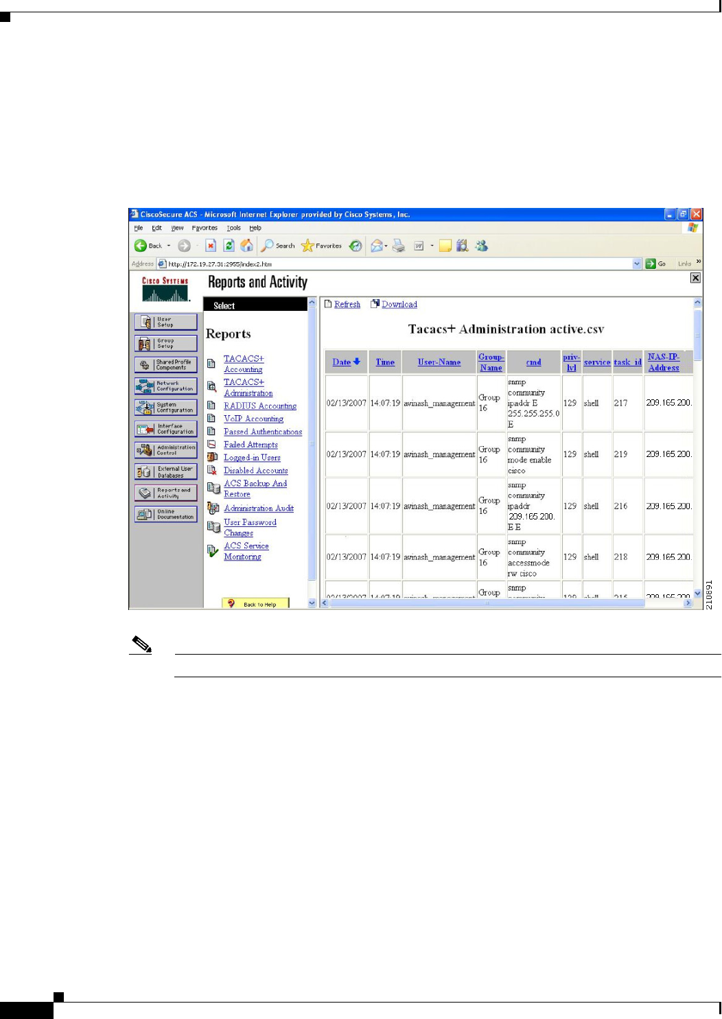
Step 1 On the ACS main page, in the left navigation pane, choose Reports and Activity.
Step 2 Under Reports, choose TACACS+ Administration.
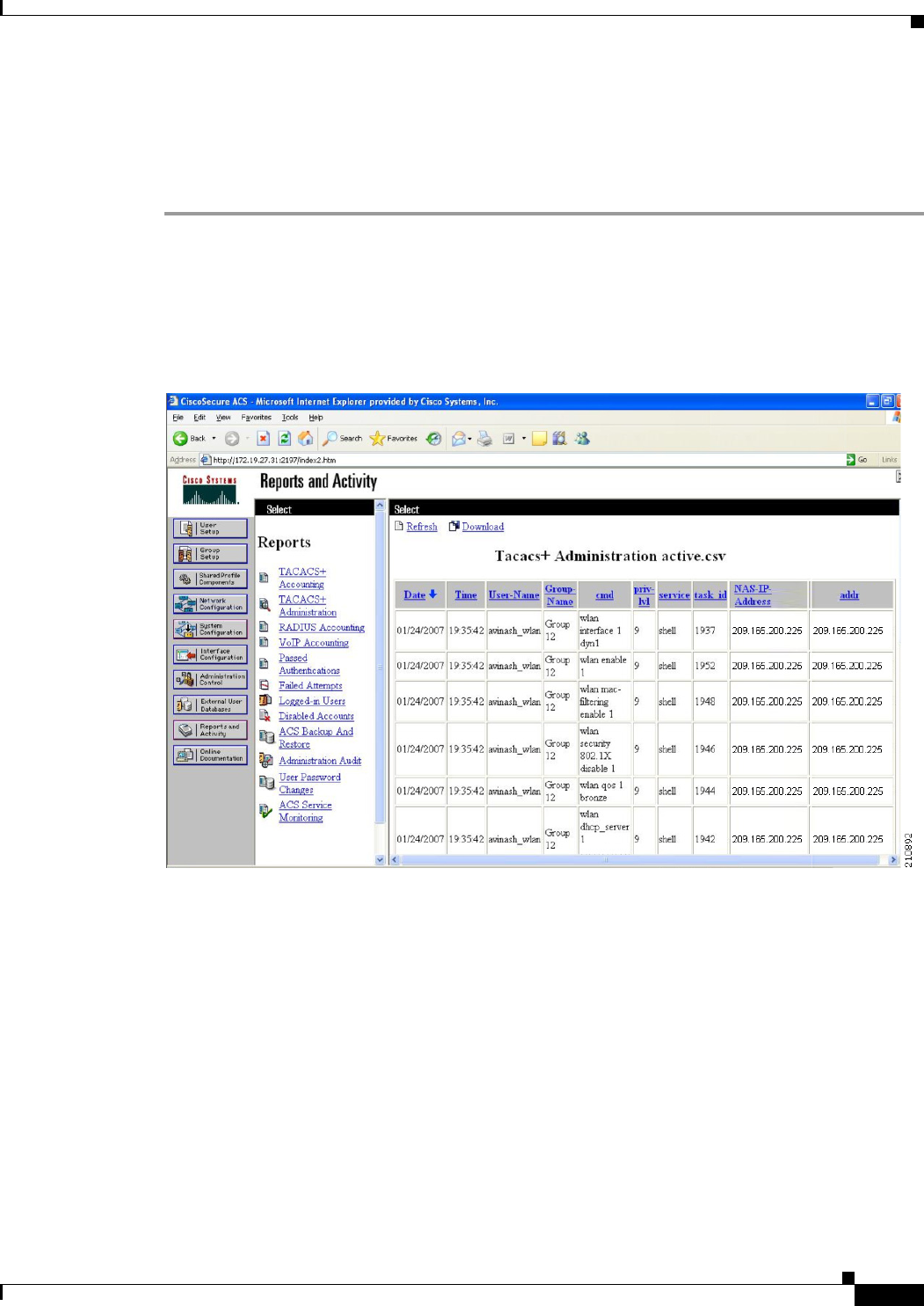
Step 3 Click the .csv file corresponding to the date of the logs you want to view. The TACACS+ Administration
.csv page appears (see Figure 6-12).
Figure 6-12 TACACS+ Administration .csv Page on CiscoSecure ACS
This page provides the following information:
• The date and time the action was taken
• The name and assigned role of the user who took the action
• The group to which the user belongs
• The specific action that the user took
• The privilege level of the user who executed the action
• The IP address of the controller
• The IP address of the laptop or workstation from which the action was executed
6-30
Cisco Wireless LAN Controller Configuration Guide
OL-21524-02
Chapter 6 Configuring Security Solutions
Configuring TACACS+
Sometimes a single action (or command) is logged multiple times, once for each parameter in the
command. For example, if you enter the snmp community ipaddr ip_address subnet_mask
community_name command, the IP address may be logged on one line while the subnet mask and
community name are logged as “E.” On another line, the subnet mask maybe logged while the IP address
and community name are logged as “E.” See the first and third lines in the example in Figure 6-13.
Figure 6-13 TACACS+ Administration .csv Page on CiscoSecure ACS
Note You can click Refresh at any time to refresh this page.
TACACS+ VSA
The Internet Engineering Task Force (IETF) draft standard specifies a method for communicating
vendor-specific attributes (VSAs) between the network access server and the TACACS+ server. The
IETF uses attribute 26. VSAs allow vendors to support their own extended attributes that are not suitable
for general use.
The Cisco TACACS+ implementation supports one vendor-specific option using the format
recommended in the IETF specification. The Cisco vendor ID is 9, and the supported option is vendor
type 1, which is named cisco-av-pair. The value is a string with the following format:
protocol : attribute separator value *
The protocol is a Cisco attribute for a particular type of authorization, the separator is = (equal sign) for
mandatory attributes, and * (asterisk) indicates optional attributes.
6-31
Cisco Wireless LAN Controller Configuration Guide
OL-21524-02
Chapter 6 Configuring Security Solutions
Configuring Maximum Local Database Entries
Configuring Maximum Local Database Entries
You can use the controller GUI or CLI to specify the maximum number of local database entries used
for storing user authentication information. The database entries include local management users
(including lobby ambassadors), local network users (including guest users), MAC filter entries,
exclusion list entries, and access point authorization list entries. Together they cannot exceed the
configured maximum value.
Using the GUI to Configure Maximum Local Database Entries
To configure the maximum number of local database entries using the controller GUI, follow these steps:
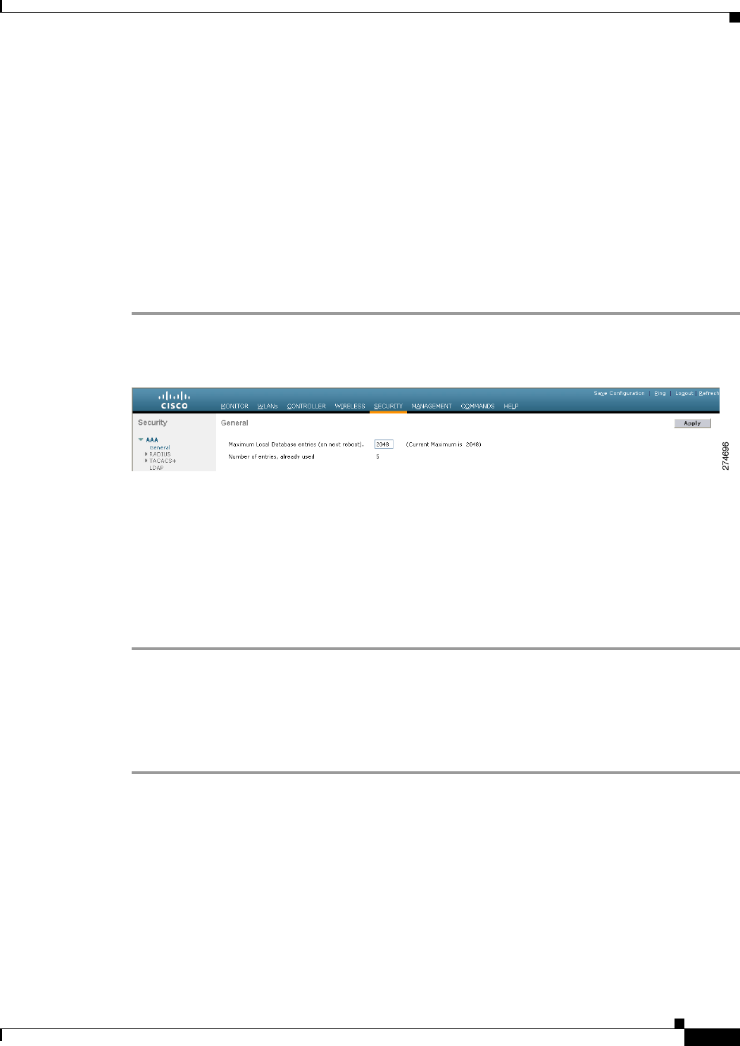
Step 1 Choose Security > AAA > General to open the General page (see Figure 6-14).
Figure 6-14 General Page
Step 2 In the Maximum Local Database Entries text box, enter a value for the maximum number of entries that
can be added to the local database the next time the controller reboots. The currently configured value
appears in parentheses to the right of the text box. The valid range is 512 to 2048, and the default setting
is 2048.
The Number of Entries, Already Used text box shows the number of entries currently in the database.
Step 3 Click Apply to commit your changes.
Step 4 Click Save Configuration to save your settings.
Using the CLI to Configure Maximum Local Database Entries
To configure the maximum number of local database entries using the controller CLI, follow these steps:
Step 1 Specify the maximum number of entries that can be added to the local database the next time the
controller reboots by entering this command:
config database size max_entries
Step 2 Save your changes by entering this command:
save config
Step 3 View the maximum number of database entries and the current database contents by entering this
command:
show database summary
Information similar to the following appears:
6-32
Cisco Wireless LAN Controller Configuration Guide
OL-21524-02
Chapter 6 Configuring Security Solutions
Configuring Local Network Users
Maximum Database Entries......................... 2048
Maximum Database Entries On Next Reboot.......... 2048
Database Contents
MAC Filter Entries........................... 2
Exclusion List Entries....................... 0
AP Authorization List Entries................ 1
Management Users............................. 1
Local Network Users.......................... 1
Local Users.............................. 1
Guest Users.............................. 0
Total..................................... 5
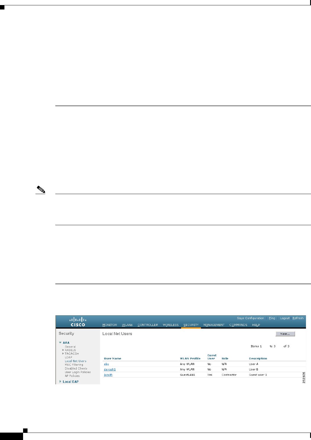
Configuring Local Network Users
This section explains how to add local network users to the local user database on the controller. The
local user database stores the credentials (username and password) of all the local network users. These
credentials are then used to authenticate the users. For example, local EAP may use the local user
database as its backend database to retrieve user credentials. See the “Configuring Local EAP” section
on page 6-42 for more information.
Note The controller passes client information to the RADIUS authentication server first. If the client
information does not match a RADIUS database entry, the local user database is polled. Clients located
in this database are granted access to network services if the RADIUS authentication fails or does not
exist.
You can configure local network users through either the GUI or the CLI.
Using the GUI to Configure Local Network Users
To configure local network users using the controller GUI, follow these steps:
Step 1 Choose Security > AAA > Local Net Users to open the Local Net Users page (see Figure 6-15).
Figure 6-15 Local Net Users Page
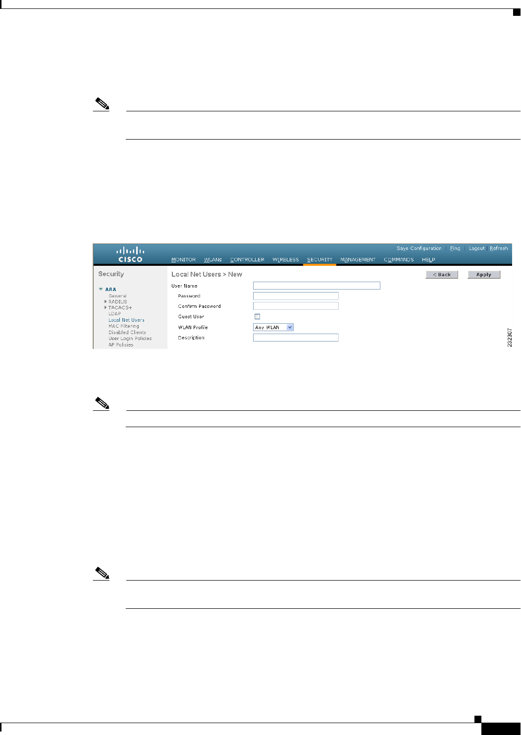
6-33
Cisco Wireless LAN Controller Configuration Guide
OL-21524-02
Chapter 6 Configuring Security Solutions
Configuring Local Network Users
This page lists any local network users that have already been configured. It also specifies any guest
users and the QoS role to which they are assigned (if applicable). See the“Configuring Quality of
Service” section on page 4-68 for information on configuring QoS roles.
Note If you want to delete an existing user, hover your cursor over the blue drop-down arrow for that
user and choose Remove.
Step 2 Perform one of the following:
• To edit an existing local network user, click the username for that user. The Local Net Users > Edit
page appears.
• To add a local network user, click New. The Local Net Users > New page appears (see Figure 6-16).
Figure 6-16 Local Net Users > New Page
Step 3 If you are adding a new user, enter a username for the local user in the User Name text box. You can
enter up to 24 alphanumeric characters.
Note Local network usernames must be unique because they are all stored in the same database.
Step 4 In the Password and Confirm Password text boxes, enter a password for the local user. You can enter up
to 24 alphanumeric characters.
Step 5 If you are adding a new user, select the Guest User check box if you want to limit the amount of time
that the user has access to the local network. The default setting is unselected.
Step 6 If you are adding a new user and you selected the Guest User check box, enter the amount of time (in
seconds) that the guest user account is to remain active in the Lifetime text box. The valid range is 60 to
2,592,000 seconds (30 days) inclusive, and the default setting is 86,400 seconds.
Step 7 If you are adding a new user, you selected the Guest User check box, and you want to assign a QoS role
to this guest user, select the Guest User Role check box. The default setting is unselected.
Note If you do not assign a QoS role to a guest user, the bandwidth contracts for this user are defined
in the QoS profile for the WLAN.
Step 8 If you are adding a new user and you selected the Guest User Role check box, choose the QoS role that
you want to assign to this guest user from the Role drop-down list.

6-34
Cisco Wireless LAN Controller Configuration Guide
OL-21524-02
Chapter 6 Configuring Security Solutions
Configuring Local Network Users
Note If you want to create a new QoS role, see the “Configuring Quality of Service” section on
page 4-68 for instructions.
Step 9 From the WLAN Profile drop-down list, choose the name of the WLAN that is to be accessed by the
local user. If you choose Any WLAN, which is the default setting, the user can access any of the
configured WLANs.
Step 10 In the Description text box, enter a descriptive title for the local user (such as “User 1”).
Step 11 Click Apply to commit your changes.
Step 12 Click Save Configuration to save your changes.
Using the CLI to Configure Local Network Users
To configure local network users using the controller CLI, use these commands:
Note See the “Using the GUI to Configure Local Network Users” section on page 6-32 for the valid ranges
and default values of the parameters used in the CLI commands.
• Configure a local network user by entering these commands:
–
config netuser add username password wlan wlan_id userType permanent description
description—Adds a permanent user to the local user database on the controller.
–
config netuser add username password {wlan | guestlan} {wlan_id | guest_lan_id} userType
guest lifetime seconds description description—Adds a guest user on a WLAN or wired guest
LAN to the local user database on the controller.
Note Instead of adding a permanent user or a guest user to the local user database from the
controller, you can choose to create an entry on the RADIUS server for the user and enable
RADIUS authentication for the WLAN on which web authentication is performed.
–
config netuser delete username—Deletes a user from the local user database on the controller.
Note Local network usernames must be unique because they are all stored in the same database.
• See information related to the local network users configured on the controller by entering these
commands:
–
show netuser detail username—Shows the configuration of a particular user in the local user
database.
–
show netuser summary—Lists all the users in the local user database.
For example, information similar to the following appears for the show netuser detail username
command:
User Name............................... abc
WLAN Id................................. Any
Lifetime................................ Permanent

6-35
Cisco Wireless LAN Controller Configuration Guide
OL-21524-02
Chapter 6 Configuring Security Solutions
Configuring Local Network Users
Description........................... test user
• Save your changes by entering this command:
save config
Configuring Password Policies
The password policies allows you to enforce strong password checks on newly created passwords for
additional management users of controller and access point. The following are the requirements enforced
on the new password:
Note When the controller is upgraded from old version, all the old passwords are maintained as it is, even
though the passwords are weak. After the system upgrade, if strong password checks are enabled, the
same is enforced from that time and the strength of previously added passwords will not be checked or
altered.
Note Depending on the settings done in the Password Policy page, the local management and access point user
configuration is affected.
You can configure Password Policies either through the GUI or the CLI.
Using the GUI to Configure Password Policies
To configure Password Policies using the controller GUI, follow these steps:
Step 1 Choose Security > AAA > Password Policies to open the Password Policies page.
Step 2 Select the Password must contain characters from at least 3 different classes check box if you want your
password to contain characters from at least three of the following classes: lower case letters, upper case
letters, digits, and special characters.
Step 3 Select No character can be repeated more than 3 times consecutively check box if you do not want
character in the new password to repeat more than three times consecutively.
Step 4 Select Password cannot be the default words like cisco, admin check box if you do not want the password
to contain words such as Cisco, ocsic, admin, nimda, or any variant obtained by changing the
capitalization of letters or by substituting 1, |, or ! or substituting 0 for o or substituting $ for s.
Step 5 Select Password cannot contain username or reverse of username check box if you do not want the
password to contain a username or the reverse letters of a username.
Step 6 Click Apply to commit your changes.
Step 7 Click Save Configuration to save your changes.
Using the CLI to Configure Password Policies
To configure Password Policies using the controller CLI, follow these steps:

6-36
Cisco Wireless LAN Controller Configuration Guide
OL-21524-02
Chapter 6 Configuring Security Solutions
Configuring LDAP
Step 1 Enable or disable strong password check for AP and WLC by entering the following command:
config switchconfig strong-pwd {case-check | consecutive-check | default-check | username-check |
all-check} {enable | disable}
where
• case-check—checks the occurrence of same character thrice consecutively
• consecutive-check—checks the default values or its variants are being used.
• default-check—checks either username or its reverse is being used.
• all-checks—enables/disables all the strong password checks.
Step 2 See the configured options for strong password check using the following command:
show switchconfig
Information similar to the following appears:
802.3x Flow Control Mode......................... Disabled
FIPS prerequisite features....................... Disabled
secret obfuscation............................... Enabled
Strong Password Check Features:
case-check ...........Enabled
consecutive-check ....Enabled
default-check .......Enabled
username-check ......Enabled
Configuring LDAP
This section explains how to configure a Lightweight Directory Access Protocol (LDAP) server as a
backend database, similar to a RADIUS or local user database. An LDAP backend database allows the
controller to query an LDAP server for the credentials (username and password) of a particular user.
These credentials are then used to authenticate the user. For example, local EAP may use an LDAP server
as its backend database to retrieve user credentials. See the “Configuring Local EAP” section on
page 6-42 for more information.
Note The LDAP backend database supports these local EAP methods: EAP-TLS, EAP-FAST/GTC, and
PEAPv1/GTC. LEAP, EAP-FAST/MSCHAPv2, and PEAPv0/MSCHAPv2 are also supported but only
if the LDAP server is set up to return a clear-text password.
Note Cisco wireless LAN controllers support Local EAP authentication against external LDAP databases such
as Microsoft Active Directory and Novell’s eDirectory. For more information about configuring the
controller for Local EAP authentication against Novell’s eDirectory, see the Configure Unified Wireless
Network for Authentication Against Novell's eDirectory Database whitepaper at
http://www.cisco.com/en/US/products/ps6366/products_white_paper09186a0080b4cd24.shtml.
Using the GUI to Configure LDAP
To configure LDAP using the controller GUI, follow these steps:
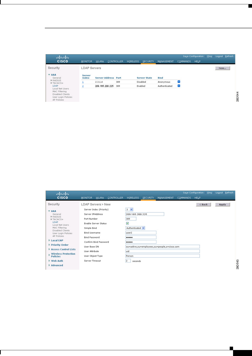
6-37
Cisco Wireless LAN Controller Configuration Guide
OL-21524-02
Chapter 6 Configuring Security Solutions
Configuring LDAP
Step 1 Choose Security > AAA > LDAP to open the LDAP Servers page (see Figure 6-17).
Figure 6-17 LDAP Servers Page
This page lists any LDAP servers that have already been configured.
• If you want to delete an existing LDAP server, hover your cursor over the blue drop-down arrow for
that server and choose Remove.
• If you want to make sure that the controller can reach a particular server, hover your cursor over the
blue drop-down arrow for that server and choose Ping.
Step 2 Perform one of the following:
• To edit an existing LDAP server, click the index number for that server. The LDAP Servers > Edit
page appears.
• To add an LDAP server, click New. The LDAP Servers > New page appears (see Figure 6-18).
Figure 6-18 LDAP Servers > New Page
Step 3 If you are adding a new server, choose a number from the Server Index (Priority) drop-down list to
specify the priority order of this server in relation to any other configured LDAP servers. You can
configure up to 17 servers. If the controller cannot reach the first server, it tries the second one in the list
and so on.
Step 4 If you are adding a new server, enter the IP address of the LDAP server in the Server IP Address text box.
Step 5 If you are adding a new server, enter the LDAP server’s TCP port number in the Port Number text box.
The valid range is 1 to 65535, and the default value is 389.
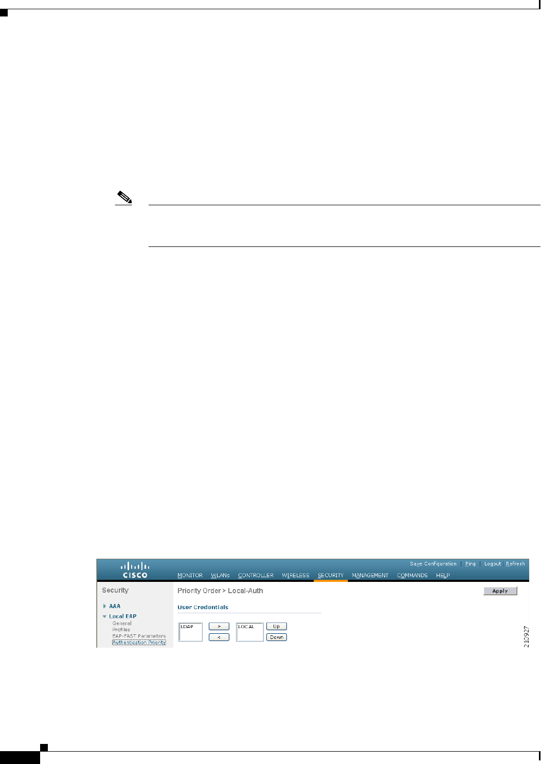
6-38
Cisco Wireless LAN Controller Configuration Guide
OL-21524-02
Chapter 6 Configuring Security Solutions
Configuring LDAP
Step 6 Select the Enable Server Status check box to enable this LDAP server or unselect it to disable it. The
default value is disabled.
Step 7 From the Simple Bind drop-down list, choose Anonymous or Authenticated to specify the local
authentication bind method for the LDAP server. The Anonymous method allows anonymous access to
the LDAP server. The Authenticated method requires that a username and password be entered to secure
access. The default value is Anonymous.
Step 8 If you chose Authenticated in Step 7, follow these steps:
a. In the Bind Username text box, enter a username to be used for local authentication to the LDAP
server. The username can contain up to 80 characters.
Note If the username starts with “cn=” (in lowercase letters), the controller assumes that the
username includes the entire LDAP database path and does not append the user base DN.
This designation allows the authenticated bind user to be outside the user base DN.
b. In the Bind Password and Confirm Bind Password text boxes, enter a password to be used for local
authentication to the LDAP server. The password can contain up to 32 characters.
Step 9 In the User Base DN text box, enter the distinguished name (DN) of the subtree in the LDAP server that
contains a list of all the users. For example, ou=organizational unit, .ou=next organizational unit, and
o=corporation.com. If the tree containing users is the base DN, type o=corporation.com or
dc=corporation,dc=com.
Step 10 In the User Attribute text box, enter the name of the attribute in the user record that contains the
username. You can obtain this attribute from your directory server.
Step 11 In the User Object Type text box, enter the value of the LDAP objectType attribute that identifies the
record as a user. Often, user records have several values for the objectType attribute, some of which are
unique to the user and some of which are shared with other object types.
Step 12 In the Server Timeout text box, enter the number of seconds between retransmissions. The valid range
is 2 to 30 seconds, and the default value is 2 seconds.
Step 13 Click Apply to commit your changes.
Step 14 Click Save Configuration to save your changes.
Step 15 Specify LDAP as the priority backend database server for local EAP authentication as follows:
a. Choose Security > Local EAP > Authentication Priority to open the Priority Order > Local-Auth
page (see Figure 6-19).
Figure 6-19 Priority Order > Local-Auth Page
b. Highlight LOCAL and click < to move it to the left User Credentials box.
c. Highlight LDAP and click > to move it to the right User Credentials box. The database that appears
at the top of the right User Credentials box is used when retrieving user credentials.
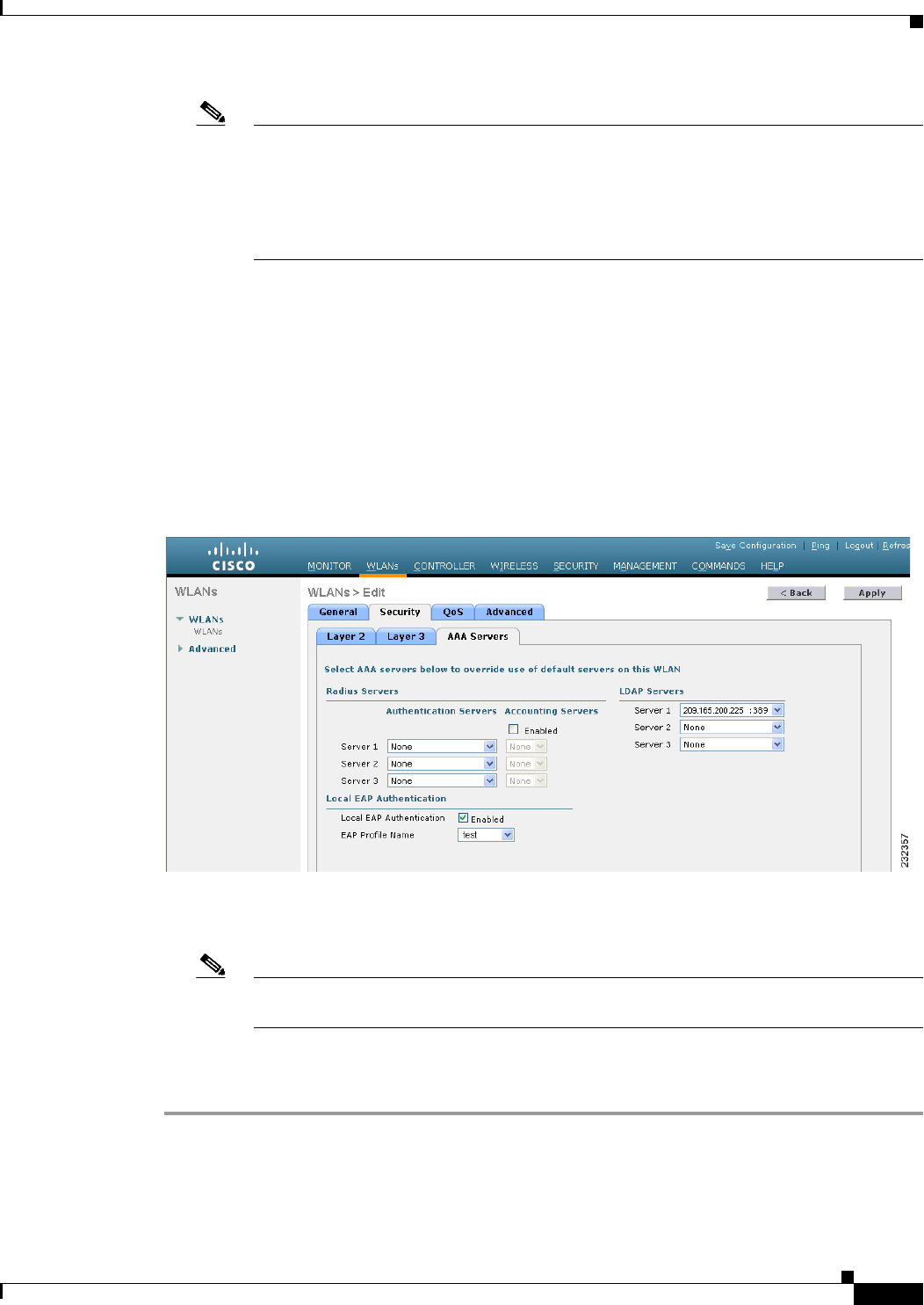
6-39
Cisco Wireless LAN Controller Configuration Guide
OL-21524-02
Chapter 6 Configuring Security Solutions
Configuring LDAP
Note If both LDAP and LOCAL appear in the right User Credentials box with LDAP on the top
and LOCAL on the bottom, local EAP attempts to authenticate clients using the LDAP
backend database and fails over to the local user database if the LDAP servers are not
reachable. If the user is not found, the authentication attempt is rejected. If LOCAL is on the
top, local EAP attempts to authenticate using only the local user database. It does not fail
over to the LDAP backend database.
d. Click Apply to commit your changes.
e. Click Save Configuration to save your changes.
Step 16 (Optional) Assign specific LDAP servers to a WLAN as follows:
a. Choose WLANs to open the WLANs page.
b. Click the ID number of the desired WLAN.
c. When the WLANs > Edit page appears, choose the Security > AAA Servers tabs to open the
WLANs > Edit (Security > AAA Servers) page (see Figure 6-20).
Figure 6-20 WLANs > Edit (Security > AAA Servers) Page
d. From the LDAP Servers drop-down lists, choose the LDAP server(s) that you want to use with this
WLAN. You can choose up to three LDAP servers, which are tried in priority order.
Note These LDAP servers apply only to WLANs with web authentication enabled. They are not
used by local EAP.
e. Click Apply to commit your changes.
f. Click Save Configuration to save your changes.

6-40
Cisco Wireless LAN Controller Configuration Guide
OL-21524-02
Chapter 6 Configuring Security Solutions
Configuring LDAP
Using the CLI to Configure LDAP
To configure LDAP using the controller CLI, use these commands:
Note See the “Using the GUI to Configure LDAP” section on page 6-36 for the valid ranges and default values
of the parameters used in the CLI commands.
• Configure an LDAP server by entering these commands:
–
config ldap add index server_ip_address port# user_base user_attr user_type—
Adds an LDAP server.
–
config ldap delete index—Deletes a previously added LDAP server.
–
config ldap {enable | disable} index—Enables or disables an LDAP server.
–
config ldap simple-bind {anonymous index | authenticated index username username
password password}—Specifies the local authentication bind method for the LDAP server. The
anonymous method allows anonymous access to the LDAP server whereas the authenticated
method requires that a username and password be entered to secure access. The default value is
anonymous.
Note The username can contain up to 80 characters.
Note If the username starts with “cn=” (in lowercase letters), the controller assumes that the
username includes the entire LDAP database path and does not append the user base
DN. This designation allows the authenticated bind user to be outside the user base DN.
–
config ldap retransmit-timeout index timeout—Configures the number of seconds between
retransmissions for an LDAP server.
• Specify LDAP as the priority backend database server by entering this command:
config local-auth user-credentials ldap
Note If you enter the config local-auth user-credentials ldap local command, local EAP
attempts to authenticate clients using the LDAP backend database and fails over to the local
user database if the LDAP servers are not reachable. If the user is not found, the
authentication attempt is rejected. If you enter the config local-auth user-credentials local
ldap command, local EAP attempts to authenticate using only the local user database. It
does not fail over to the LDAP backend database.
• (Optional) Assign specific LDAP servers to a WLAN by entering these commands:
–
config wlan ldap add wlan_id server_index—Links a configured LDAP server to a WLAN.
Note The LDAP servers specified in this command apply only to WLANs with web
authentication enabled. They are not used by local EAP.
–
config wlan ldap delete wlan_id {all | index}—Deletes a specific or all configured LDAP
server(s) from a WLAN.

6-41
Cisco Wireless LAN Controller Configuration Guide
OL-21524-02
Chapter 6 Configuring Security Solutions
Configuring LDAP
• View information pertaining to configured LDAP servers by entering these commands:
–
show ldap summary—Shows a summary of the configured LDAP servers.
–
show ldap index—Shows detailed LDAP server information.
–
show ldap statistics—Shows LDAP server statistics.
–
show wlan wlan_id—Shows the LDAP servers that are applied to a WLAN.
Information similar to the following appears when you enter the show ldap index command:
Server Index..................................... 2
Address.......................................... 10.10.20.22
Port............................................. 389
Enabled.......................................... Yes
User DN.......................................... ou=active,ou=employees,ou=people,
o=cisco.com
User Attribute................................... uid
User Type........................................ Person
Retransmit Timeout............................... 2 seconds
Bind Method ..................................... Authenticated
Bind Username................................. user1
Information similar to the following appears when you enter the show ldap summary command:
Idx Server Address Port Enabled
--- --------------- ---- -------
1 2.3.1.4 389 No
2 10.10.20.22 389 Yes
Information similar to the following appears when you enter the show ldap statistics command:
Server Index..................................... 1
Server statistics:
Initialized OK................................. 0
Initialization failed.......................... 0
Initialization retries......................... 0
Closed OK...................................... 0
Request statistics:
Received....................................... 0
Sent........................................... 0
OK............................................. 0
Success........................................ 0
Authentication failed.......................... 0
Server not found............................... 0
No received attributes......................... 0
No passed username............................. 0
Not connected to server........................ 0
Internal error................................. 0
Retries........................................ 0
Server Index..................................... 2
...
• Make sure the controller can reach the LDAP server by entering this command:
ping server_ip_address
• Save your changes by entering this command:
save config
• Enable or disable debugging for LDAP by entering this command:
debug aaa ldap {enable | disable}

6-42
Cisco Wireless LAN Controller Configuration Guide
OL-21524-02
Chapter 6 Configuring Security Solutions
Configuring Local EAP
Configuring Local EAP
Local EAP is an authentication method that allows users and wireless clients to be authenticated locally.
It is designed for use in remote offices that want to maintain connectivity to wireless clients when the
backend system becomes disrupted or the external authentication server goes down. When you enable
local EAP, the controller serves as the authentication server and the local user database, which removes
dependence on an external authentication server. Local EAP retrieves user credentials from the local user
database or the LDAP backend database to authenticate users. Local EAP supports LEAP, EAP-FAST,
EAP-TLS, PEAPv0/MSCHAPv2, and PEAPv1/GTC authentication between the controller and wireless
clients.
Note The LDAP backend database supports these local EAP methods: EAP-TLS, EAP-FAST/GTC, and
PEAPv1/GTC. LEAP, EAP-FAST/MSCHAPv2, and PEAPv0/MSCHAPv2 are also supported but only
if the LDAP server is set up to return a clear-text password.
Note Cisco wireless LAN controllers support Local EAP authentication against external LDAP databases such
as Microsoft Active Directory and Novell’s eDirectory. For more information about configuring the
controller for Local EAP authentication on Novell’s eDirectory, see the Configure Unified Wireless
Network for Authentication Against Novell's eDirectory Database whitepaper at
http://www.cisco.com/en/US/products/ps6366/products_white_paper09186a0080b4cd24.shtml.
Note If any RADIUS servers are configured on the controller, the controller tries to authenticate the wireless
clients using the RADIUS servers first. Local EAP is attempted only if no RADIUS servers are found,
either because the RADIUS servers timed out or no RADIUS servers were configured. If four RADIUS
servers are configured, the controller attempts to authenticate the client with the first RADIUS server,
then the second RADIUS server, and then local EAP. If the client attempts to then reauthenticate
manually, the controller tries the third RADIUS server, then the fourth RADIUS server, and then local
EAP. If you never want the controller to try to authenticate clients using an external RADIUS server,
enter these CLI commands in this order:
config wlan disable wlan_id
config wlan radius_server auth disable wlan_id
config wlan enable wlan_id
Figure 6-21 provides an example of a remote office using local EAP.
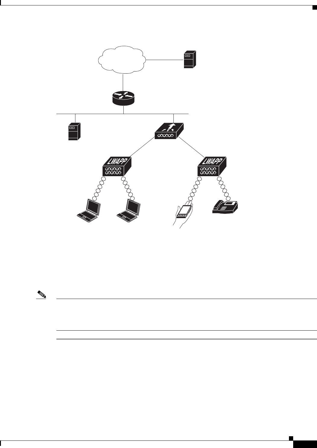
6-43
Cisco Wireless LAN Controller Configuration Guide
OL-21524-02
Chapter 6 Configuring Security Solutions
Configuring Local EAP
Figure 6-21 Local EAP Example
You can configure local EAP through either the GUI or the CLI.
Using the GUI to Configure Local EAP
To configure local EAP using the controller GUI, follow these steps:
Note EAP-TLS, PEAPv0/MSCHAPv2, and PEAPv1/GTC use certificates for authentication, and EAP-FAST
uses either certificates or PACs. The controller is shipped with Cisco-installed device and Certificate
Authority (CA) certificates. However, if you want to use your own vendor-specific certificates, they must
be imported on the controller.
Step 1 If you are configuring local EAP to use one of the EAP types listed in the note above, make sure that the
appropriate certificates and PACs (if you will use manual PAC provisioning) have been imported on the
controller. See Chapter 10, “Managing Controller Software and Configurations,” for instructions on
importing certificates and PACs.
Step 2 If you want the controller to retrieve user credentials from the local user database, make sure that you
have properly configured the local network users on the controller. See the “Configuring Local Network
Users” section on page 6-32 for instructions.
IP
LDAP server
(optional)
Wireless LAN
controller
Cisco Aironet
Lightweight Access Point
Regional office
RADIUS server
WAN
232306
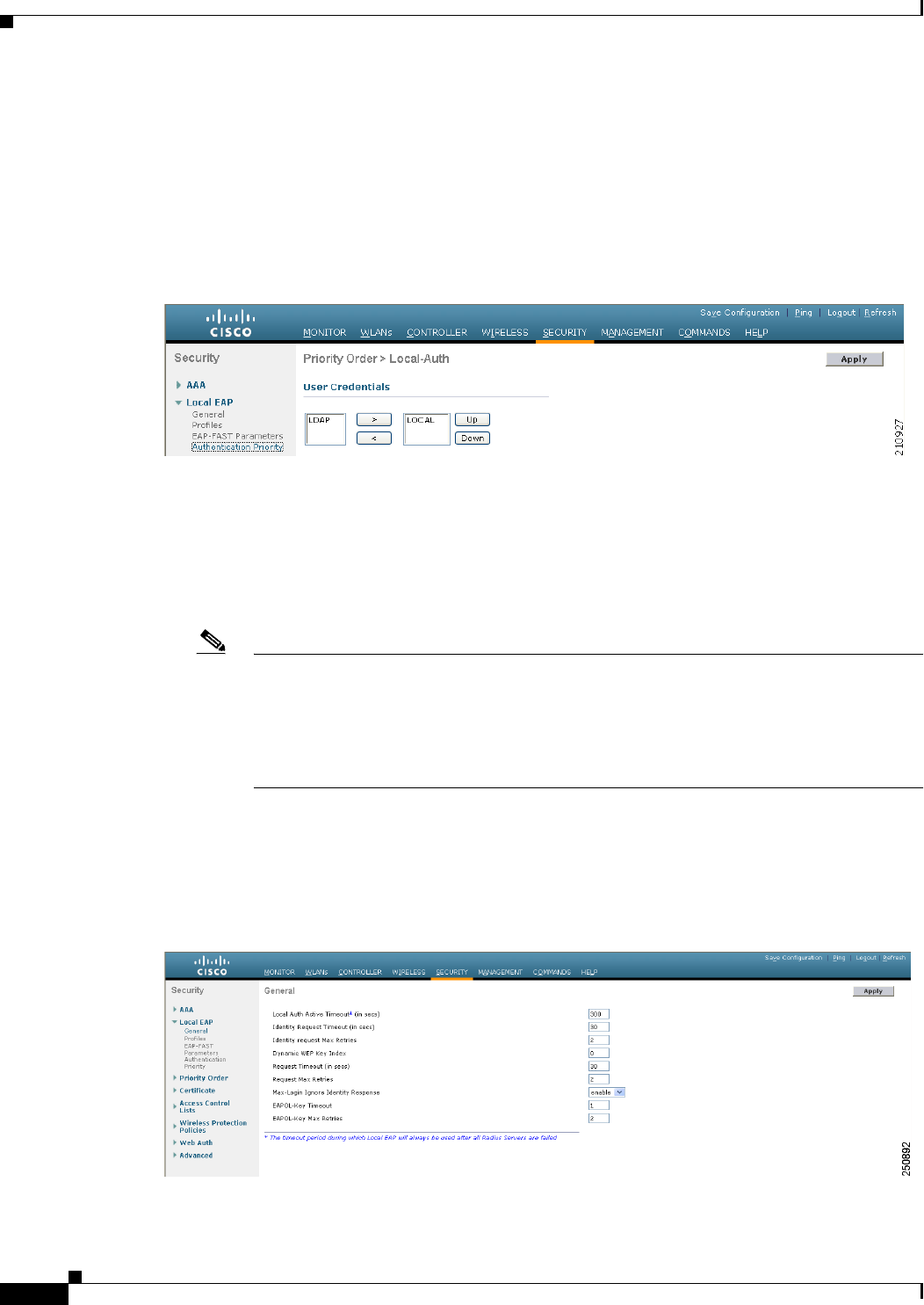
6-44
Cisco Wireless LAN Controller Configuration Guide
OL-21524-02
Chapter 6 Configuring Security Solutions
Configuring Local EAP
Step 3 If you want the controller to retrieve user credentials from an LDAP backend database, make sure that
you have properly configured an LDAP server on the controller. See the “Configuring LDAP” section on
page 6-36 for instructions.
Step 4 Specify the order in which user credentials are retrieved from the backend database servers as follows:
a. Choose Security > Local EAP > Authentication Priority to open the Priority Order > Local-Auth
page (see Figure 6-22).
Figure 6-22 Priority Order > Local-Auth Page
b. Determine the priority order in which user credentials are to be retrieved from the local and/or LDAP
databases. For example, you may want the LDAP database to be given priority over the local user
database, or you may not want the LDAP database to be considered at all.
c. When you have decided on a priority order, highlight the desired database. Then use the left and
right arrows and the Up and Down buttons to move the desired database to the top of the right User
Credentials box.
Note If both LDAP and LOCAL appear in the right User Credentials box with LDAP on the top
and LOCAL on the bottom, local EAP attempts to authenticate clients using the LDAP
backend database and fails over to the local user database if the LDAP servers are not
reachable. If the user is not found, the authentication attempt is rejected. If LOCAL is on the
top, local EAP attempts to authenticate using only the local user database. It does not fail
over to the LDAP backend database.
d. Click Apply to commit your changes.
Step 5 Specify values for the local EAP timers as follows:
a. Choose Security > Local EAP > General to open the General page (see Figure 6-23).
Figure 6-23 General Page

6-45
Cisco Wireless LAN Controller Configuration Guide
OL-21524-02
Chapter 6 Configuring Security Solutions
Configuring Local EAP
b. In the Local Auth Active Timeout text box, enter the amount of time (in seconds) in which the
controller attempts to authenticate wireless clients using local EAP after any pair of configured
RADIUS servers fails. The valid range is 1 to 3600 seconds, and the default setting is 100 seconds.
c. In the Identity Request Timeout text box, enter the amount of time (in seconds) in which the
controller attempts to send an EAP identity request to wireless clients using local EAP. The valid
range is 1 to 120 seconds, and the default setting is 30 seconds.
d. In the Identity Request Max Retries text box, enter the maximum number of times that the controller
attempts to retransmit the EAP identity request to wireless clients using local EAP. The valid range
is 1 to 20 retries, and the default setting is 20 retries.
e. In the Dynamic WEP Key Index text box, enter the key index used for dynamic wired equivalent
privacy (WEP). The default value is 0, which corresponds to a key index of 1; the valid values are 0
to 3 (key index of 1 to 4).
f. In the Request Timeout text box, enter the amount of time (in seconds) in which the controller
attempts to send an EAP request to wireless clients using local EAP. The valid range is 1 to 120
seconds, and the default setting is 30 seconds.
g. In the Request Max Retries text box, enter the maximum number of times that the controller attempts
to retransmit the EAP request to wireless clients using local EAP. The valid range is 1 to 120 retries,
and the default setting is 20 retries.
h. From the Max-Login Ignore Identity Response drop-down list, choose Enable to limit the number
of devices that can be connected to the controller with the same username. You can log in up to eight
times from different devices (PDA, laptop, IP phone, and so on) on the same controller. The default
value is enabled.
i. In the EAPOL-Key Timeout text box, enter the amount of time (in seconds) in which the controller
attempts to send an EAP key over the LAN to wireless clients using local EAP. The valid range is 1
to 5 seconds, and the default setting is 1 second.
Note If the controller and access point are separated by a WAN link, the default timeout of 1 second
may not be sufficient.
j. In the EAPOL-Key Max Retries text box, enter the maximum number of times that the controller
attempts to send an EAP key over the LAN to wireless clients using local EAP. The valid range is 0
to 4 retries, and the default setting is 2 retries.
k. Click Apply to commit your changes.
Step 6 Create a local EAP profile, which specifies the EAP authentication types that are supported on the
wireless clients as follows:
a. Choose Security > Local EAP > Profiles to open the Local EAP Profiles page (see Figure 6-24).
Figure 6-24 Local EAP Profiles Page
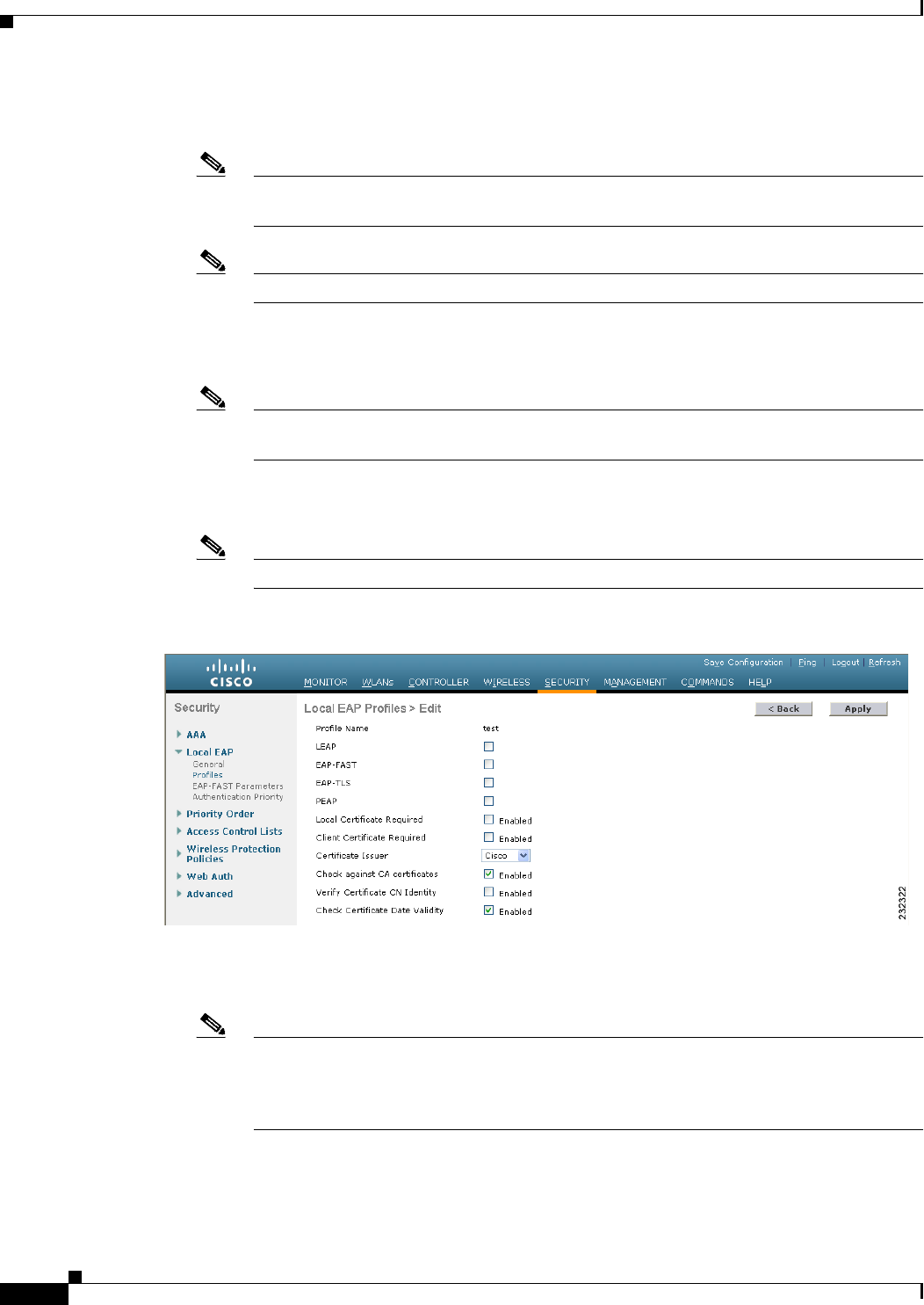
6-46
Cisco Wireless LAN Controller Configuration Guide
OL-21524-02
Chapter 6 Configuring Security Solutions
Configuring Local EAP
This page lists any local EAP profiles that have already been configured and specifies their EAP
types. You can create up to 16 local EAP profiles.
Note If you want to delete an existing profile, hover your cursor over the blue drop-down arrow
for that profile and choose Remove.
Note Local EAP Profiles are not supported on AP602 OEAP.
b. Click New to open the Local EAP Profiles > New page.
c. In the Profile Name text box, enter a name for your new profile and then click Apply.
Note You can enter up to 63 alphanumeric characters for the profile name. Make sure not to
include spaces.
d. When the Local EAP Profiles page reappears, click the name of your new profile. The Local EAP
Profiles > Edit page appears (see Figure 6-25).
Note Local EAP Profiles are not supported on AP602 OEAP.
Figure 6-25 Local EAP Profiles > Edit Page
e. Select the LEAP, EAP-FAST, EAP-TLS, and/or PEAP check boxes to specify the EAP type that
can be used for local authentication.
Note You can specify more than one EAP type per profile. However, if you choose multiple EAP
types that use certificates (such as EAP-FAST with certificates, EAP-TLS,
PEAPv0/MSCHAPv2, and PEAPv1/GTC), all of the EAP types must use the same
certificate (from either Cisco or another vendor).

6-47
Cisco Wireless LAN Controller Configuration Guide
OL-21524-02
Chapter 6 Configuring Security Solutions
Configuring Local EAP
Note If you select the PEAP check box, both PEAPv0/MSCHAPv2 or PEAPv1/GTC are enabled
on the controller.
f. If you chose EAP-FAST and want the device certificate on the controller to be used for
authentication, select the Local Certificate Required check box. If you want to use EAP-FAST
with PACs instead of certificates, leave this check box unselected, which is the default setting.
Note This option applies only to EAP-FAST because device certificates are not used with LEAP
and are mandatory for EAP-TLS and PEAP.
g. If you chose EAP-FAST and want the wireless clients to send their device certificates to the
controller in order to authenticate, select the Client Certificate Required check box. If you want
to use EAP-FAST with PACs instead of certificates, leave this check box unselected, which is the
default setting.
Note This option applies only to EAP-FAST because client certificates are not used with LEAP
or PEAP and are mandatory for EAP-TLS.
h. If you chose EAP-FAST with certificates, EAP-TLS, or PEAP, choose which certificates will be sent
to the client, the ones from Cisco or the ones from another Vendor, from the Certificate Issuer
drop-down list. The default setting is Cisco.
i. If you chose EAP-FAST with certificates or EAP-TLS and want the incoming certificate from the
client to be validated against the CA certificates on the controller, select the Check against CA
certificates check box. The default setting is enabled.
j. If you chose EAP-FAST with certificates or EAP-TLS and want the common name (CN) in the
incoming certificate to be validated against the CA certificates’ CN on the controller, select the
Verify Certificate CN Identity check box. The default setting is disabled.
k. If you chose EAP-FAST with certificates or EAP-TLS and want the controller to verify that the
incoming device certificate is still valid and has not expired, select the Check Certificate Date
Validi ty check box. The default setting is enabled.
Note Certificate date validity is checked against the current UTC (GMT) time that is configured
on the controller. Timezone offset will be ignored.
l. Click Apply to commit your changes.
Step 7 If you created an EAP-FAST profile, follow these steps to configure the EAP-FAST parameters:
a. Choose Security > Local EAP > EAP-FAST Parameters to open the EAP-FAST Method
Parameters page (see Figure 6-26).
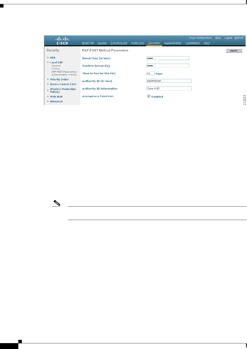
6-48
Cisco Wireless LAN Controller Configuration Guide
OL-21524-02
Chapter 6 Configuring Security Solutions
Configuring Local EAP
Figure 6-26 EAP-FAST Method Parameters Page
b. In the Server Key and Confirm Server Key text boxes, enter the key (in hexadecimal characters) used
to encrypt and decrypt PACs.
c. In the Time to Live for the PAC text box, enter the number of days for the PAC to remain viable. The
valid range is 1 to 1000 days, and the default setting is 10 days.
d. In the Authority ID text box, enter the authority identifier of the local EAP-FAST server in
hexadecimal characters. You can enter up to 32 hexadecimal characters, but you must enter an even
number of characters.
e. In the Authority ID Information text box, enter the authority identifier of the local EAP-FAST server
in text format.
f. If you want to enable anonymous provisioning, select the Anonymous Provision check box. This
feature allows PACs to be sent automatically to clients that do not have one during PAC
provisioning. If you disable this feature, PACS must be manually provisioned. The default setting is
enabled.
Note If the local and/or client certificates are required and you want to force all EAP-FAST clients
to use certificates, unselect the Anonymous Provision check box.
g. Click Apply to commit your changes.
Step 8 Enable local EAP on a WLAN as follows:
a. Choose WLANs to open the WLANs page.
b. Click the ID number of the desired WLAN.
c. When the WLANs > Edit page appears, choose the Security > AAA Servers tabs to open the
WLANs > Edit (Security > AAA Servers) page (see Figure 6-27).
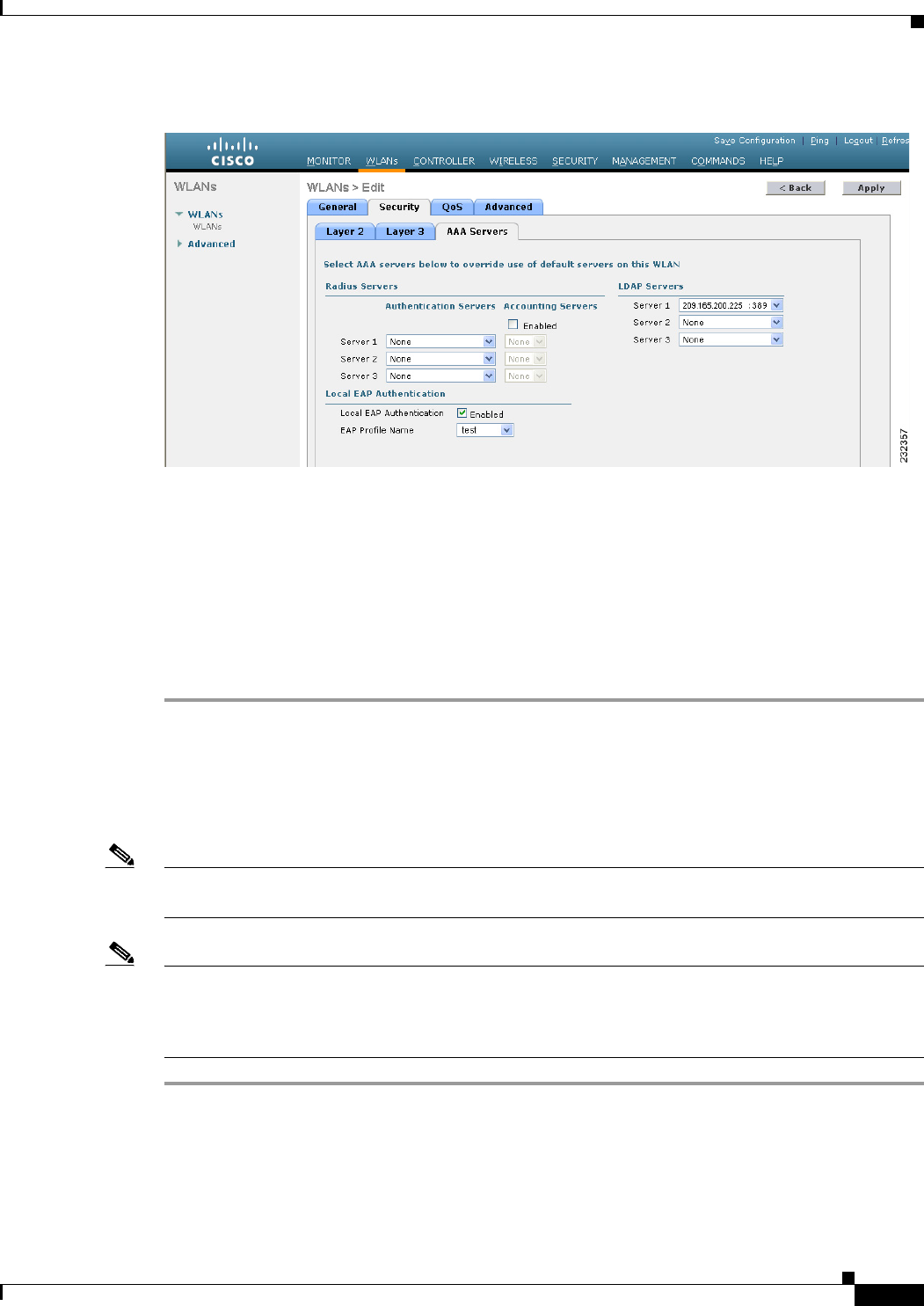
6-49
Cisco Wireless LAN Controller Configuration Guide
OL-21524-02
Chapter 6 Configuring Security Solutions
Configuring Local EAP
Figure 6-27 WLANs > Edit (Security > AAA Servers) Page
d. Select the Local EAP Authentication check box to enable local EAP for this WLAN.
e. From the EAP Profile Name drop-down list, choose the EAP profile that you want to use for this
WLAN.
f. If desired, choose the LDAP server that you want to use with local EAP on this WLAN from the
LDAP Servers drop-down lists.
g. Click Apply to commit your changes.
Step 9 Click Save Configuration to save your changes.
Using the CLI to Configure Local EAP
To configure local EAP using the controller CLI, follow these steps:
Note See the “Using the GUI to Configure Local EAP” section on page 6-43 for the valid ranges and default
values of the parameters used in the CLI commands.
Note EAP-TLS, PEAPv0/MSCHAPv2, and PEAPv1/GTC use certificates for authentication, and EAP-FAST
uses either certificates or PACs. The controller is shipped with Cisco-installed device and Certificate
Authority (CA) certificates. However, if you want to use your own vendor-specific certificates, they must
be imported on the controller.
Step 1 If you are configuring local EAP to use one of the EAP types listed in the note above, make sure that the
appropriate certificates and PACs (if you will use manual PAC provisioning) have been imported on the
controller. See Chapter 10, “Managing Controller Software and Configurations,” for instructions on
importing certificates and PACs.

6-50
Cisco Wireless LAN Controller Configuration Guide
OL-21524-02
Chapter 6 Configuring Security Solutions
Configuring Local EAP
Step 2 If you want the controller to retrieve user credentials from the local user database, make sure that you
have properly configured the local network users on the controller. See the “Configuring Local Network
Users” section on page 6-32 for instructions.
Step 3 If you want the controller to retrieve user credentials from an LDAP backend database, make sure that
you have properly configured an LDAP server on the controller. See the “Configuring LDAP” section on
page 6-36 for instructions.
Step 4 Specify the order in which user credentials are retrieved from the local and/or LDAP databases by
entering this command:
config local-auth user-credentials {local | ldap}
Note If you enter the config local-auth user-credentials ldap local command, local EAP attempts to
authenticate clients using the LDAP backend database and fails over to the local user database
if the LDAP servers are not reachable. If the user is not found, the authentication attempt is
rejected. If you enter the config local-auth user-credentials local ldap command, local EAP
attempts to authenticate using only the local user database. It does not fail over to the LDAP
backend database.
Step 5 Specify values for the local EAP timers by entering these commands:
• config local-auth active-timeout timeout—Specifies the amount of time (in seconds) in which the
controller attempts to authenticate wireless clients using local EAP after any pair of configured
RADIUS servers fails. The valid range is 1 to 3600 seconds, and the default setting is 100 seconds.
• config advanced eap identity-request-timeout timeout—Specifies the amount of time (in seconds)
in which the controller attempts to send an EAP identity request to wireless clients using local EAP.
The valid range is 1 to 120 seconds, and the default setting is 30 seconds.
• config advanced eap identity-request-retries retries—Specifies the maximum number of times
that the controller attempts to retransmit the EAP identity request to wireless clients using local
EAP. The valid range is 1 to 20 retries, and the default setting is 20 retries.
• config advanced eap key-index index—Specifies the key index used for dynamic wired equivalent
privacy (WEP). The default value is 0, which corresponds to a key index of 1; the valid values are 0
to 3 (key index of 1 to 4).
• config advanced eap request-timeout timeout—Specifies the amount of time (in seconds) in which
the controller attempts to send an EAP request to wireless clients using local EAP. The valid range
is 1 to 120 seconds, and the default setting is 30 seconds.
• config advanced eap request-retries retries—Specifies the maximum number of times that the
controller attempts to retransmit the EAP request to wireless clients using local EAP. The valid
range is 1 to 120 retries, and the default setting is 20 retries.
• config advanced eap eapol-key-timeout timeout—Specifies the amount of time (in seconds) in
which the controller attempts to send an EAP key over the LAN to wireless clients using local EAP.
The valid range is 1 to 5 seconds, and the default setting is 1 second.
Note If the controller and access point are separated by a WAN link, the default timeout of 1 second
may not be sufficient.
• config advanced eap eapol-key-retries retries—Specifies the maximum number of times that the
controller attempts to send an EAP key over the LAN to wireless clients using local EAP. The valid
range is 0 to 4 retries, and the default setting is 2 retries.

6-51
Cisco Wireless LAN Controller Configuration Guide
OL-21524-02
Chapter 6 Configuring Security Solutions
Configuring Local EAP
• config advanced eap max-login-ignore-identity-response {enable | disable}—When enabled,
this command limits the number of devices that can be connected to the controller with the same
username. You can log in up to eight times from different devices (PDA, laptop, IP phone, and so
on) on the same controller. The default value is enabled.
Step 6 Create a local EAP profile by entering this command:
config local-auth eap-profile add profile_name
Note Do not include spaces within the profile name.
Note To delete a local EAP profile, enter the config local-auth eap-profile delete profile_name
command.
Step 7 Add an EAP method to a local EAP profile by entering this command:
config local-auth eap-profile method add method profile_name
The supported methods are leap, fast, tls, and peap.
Note If you choose peap, both PEAPv0/MSCHAPv2 or PEAPv1/GTC are enabled on the controller.
Note You can specify more than one EAP type per profile. However, if you create a profile with
multiple EAP types that use certificates (such as EAP-FAST with certificates, EAP-TLS,
PEAPv0/MSCHAPv2, and PEAPv1/GTC), all of the EAP types must use the same certificate
(from either Cisco or another vendor).
Note To delete an EAP method from a local EAP profile, enter the config local-auth eap-profile
method delete method profile_name command:
Step 8 Configure EAP-FAST parameters if you created an EAP-FAST profile by entering this command:
config local-auth method fast ?
where ? is one of the following:
• anon-prov {enable | disable}—Configures the controller to allow anonymous provisioning, which
allows PACs to be sent automatically to clients that do not have one during PAC provisioning.
• authority-id auth_id—Specifies the authority identifier of the local EAP-FAST server.
• pac-ttl days—Specifies the number of days for the PAC to remain viable.
• server-key key—Specifies the server key used to encrypt and decrypt PACs.
Step 9 Configure certificate parameters per profile by entering these commands:
• config local-auth eap-profile method fast local-cert {enable | disable} profile_name—
Specifies whether the device certificate on the controller is required for authentication.
Note This command applies only to EAP-FAST because device certificates are not used with
LEAP and are mandatory for EAP-TLS and PEAP.

6-52
Cisco Wireless LAN Controller Configuration Guide
OL-21524-02
Chapter 6 Configuring Security Solutions
Configuring Local EAP
• config local-auth eap-profile method fast client-cert {enable | disable} profile_name—
Specifies whether wireless clients are required to send their device certificates to the controller in
order to authenticate.
Note This command applies only to EAP-FAST because client certificates are not used with
LEAP or PEAP and are mandatory for EAP-TLS.
• config local-auth eap-profile cert-issuer {cisco | vendor} profile_name—If you specified
EAP-FAST with certificates, EAP-TLS, or PEAP, specifies whether the certificates that will be sent
to the client are from Cisco or another vendor.
• config local-auth eap-profile cert-verify ca-issuer {enable | disable} profile_name—If you chose
EAP-FAST with certificates or EAP-TLS, specifies whether the incoming certificate from the client
is to be validated against the CA certificates on the controller.
• config local-auth eap-profile cert-verify cn-verify {enable | disable} profile_name—If you chose
EAP-FAST with certificates or EAP-TLS, specifies whether the common name (CN) in the
incoming certificate is to be validated against the CA certificates’ CN on the controller.
• config local-auth eap-profile cert-verify date-valid {enable | disable} profile_name—If you
chose EAP-FAST with certificates or EAP-TLS, specifies whether the controller is to verify that the
incoming device certificate is still valid and has not expired.
Step 10 Enable local EAP and attach an EAP profile to a WLAN by entering this command:
config wlan local-auth enable profile_name wlan_id
Note To disable local EAP for a WLAN, enter the config wlan local-auth disable wlan_id command.
Step 11 Save your changes by entering this command:
save config
Step 12 View information pertaining to local EAP by entering these commands:
• show local-auth config—Shows the local EAP configuration on the controller.
Information similar to the following appears when you enter the show local-auth config command:
User credentials database search order:
Primary ..................................... Local DB
Timer:
Active timeout .............................. 300
Configured EAP profiles:
Name ........................................ fast-cert
Certificate issuer ........................ vendor
Peer verification options:
Check against CA certificates ........... Enabled
Verify certificate CN identity .......... Disabled
Check certificate date validity ......... Enabled
EAP-FAST configuration:
Local certificate required .............. Yes
Client certificate required ............. Yes
Enabled methods ........................... fast
Configured on WLANs ....................... 1
Name ........................................ tls
Certificate issuer ........................ vendor

6-53
Cisco Wireless LAN Controller Configuration Guide
OL-21524-02
Chapter 6 Configuring Security Solutions
Configuring Local EAP
Peer verification options:
Check against CA certificates ........... Enabled
Verify certificate CN identity .......... Disabled
Check certificate date validity ......... Enabled
EAP-FAST configuration:
Local certificate required .............. No
Client certificate required ............. No
Enabled methods ........................... tls
Configured on WLANs ....................... 2
EAP Method configuration:
EAP-FAST:
Server key ................................ <hidden>
TTL for the PAC ........................... 10
Anonymous provision allowed ............... Yes
Accept client on auth prov ................ No
Authority ID .............................. 436973636f0000000000000000000000
Authority Information ..................... Cisco A-ID
• show local-auth statistics—Shows the local EAP statistics.
• show local-auth certificates—Shows the certificates available for local EAP.
• show local-auth user-credentials—Shows the priority order that the controller uses when
retrieving user credentials from the local and/or LDAP databases.
• show advanced eap—Shows the timer values for local EAP. Information similar to the following
appears:
EAP-Identity-Request Timeout (seconds)........... 1
EAP-Identity-Request Max Retries................. 20
EAP Key-Index for Dynamic WEP.................... 0
EAP Max-Login Ignore Identity Response........... enable
EAP-Request Timeout (seconds).................... 20
EAP-Request Max Retries.......................... 20
EAPOL-Key Timeout (seconds)...................... 1
EAPOL-Key Max Retries......................... 2
• show ap stats wlan Cisco_AP—Shows the EAP timeout and failure counters for a specific access
point for each WLAN. Information similar to the following appears:
WLAN 1
EAP Id Request Msg Timeouts................... 0
EAP Id Request Msg Timeouts Failures.......... 0
EAP Request Msg Timeouts...................... 2
EAP Request Msg Timeouts Failures............. 1
EAP Key Msg Timeouts.......................... 0
EAP Key Msg Timeouts Failures................. 0
WLAN 2
EAP Id Request Msg Timeouts................... 1
EAP Id Request Msg Timeouts Failures.......... 0
EAP Request Msg Timeouts...................... 0
EAP Request Msg Timeouts Failures............. 0
EAP Key Msg Timeouts.......................... 3
EAP Key Msg Timeouts Failures.............. 1
• show client detail client_mac—Shows the EAP timeout and failure counters for a specific
associated client. These statistics are useful in troubleshooting client association issues. Information
similar to the following appears:
...
Client Statistics:
Number of Bytes Received................... 10
Number of Bytes Sent....................... 10

6-54
Cisco Wireless LAN Controller Configuration Guide
OL-21524-02
Chapter 6 Configuring Security Solutions
Configuring the System for SpectraLink NetLink Telephones
Number of Packets Received................. 2
Number of Packets Sent..................... 2
Number of EAP Id Request Msg Timeouts...... 0
Number of EAP Id Request Msg Failures...... 0
Number of EAP Request Msg Timeouts......... 2
Number of EAP Request Msg Failures......... 1
Number of EAP Key Msg Timeouts............. 0
Number of EAP Key Msg Failures............. 0
Number of Policy Errors.................... 0
Radio Signal Strength Indicator............ Unavailable
Signal to Noise Ratio...................... Unavailable
...
• show wlan wlan_id—Shows the status of local EAP on a particular WLAN.
Step 13 (Optional) Troubleshoot local EAP sessions by entering these commands:
• debug aaa local-auth eap method {all | errors | events | packets | sm} {enable | disable}—
Enables or disables debugging of local EAP methods.
• debug aaa local-auth eap framework {all | errors | events | packets | sm} {enable | disable}—
Enables or disables debugging of the local EAP framework.
Note In these two debug commands, sm is the state machine.
• clear stats local-auth—Clears the local EAP counters.
• clear stats ap wlan Cisco_AP—Clears the EAP timeout and failure counters for a specific access
point for each WLAN.
Configuring the System for SpectraLink NetLink Telephones
For the best integration with the Cisco UWN solution, SpectraLink NetLink Telephones require an extra
operating system configuration step: enable long preambles. The radio preamble (sometimes called a
header) is a section of data at the head of a packet that contains information that wireless devices need
when sending and receiving packets. Short preambles improve throughput performance, so they are
enabled by default. However, some wireless devices, such as SpectraLink NetLink phones, require long
preambles.
Use one of these methods to enable long preambles:
• Using the GUI to Enable Long Preambles, page 6-54
• Using the CLI to Enable Long Preambles, page 6-55
Using the GUI to Enable Long Preambles
To enable long preambles to optimize the operation of SpectraLink NetLink phones on your wireless
LAN using the controller GUI, follow these steps:
Step 1 Choose Wireless > 802.11b/g/n > Network to open the 802.11b/g Global Parameters page.

6-55
Cisco Wireless LAN Controller Configuration Guide
OL-21524-02
Chapter 6 Configuring Security Solutions
Configuring the System for SpectraLink NetLink Telephones
Step 2 If the Short Preamble check box is selected, continue with this procedure. However, if the Short
Preamble check box is unselected (which means that long preambles are enabled), the controller is
already optimized for SpectraLink NetLink phones and you do not need to continue this procedure.
Step 3 Unselect the Short Preamble check box to enable long preambles.
Step 4 Click Apply to update the controller configuration.
Note If you do not already have an active CLI session to the controller, we recommend that you start
a CLI session to reboot the controller and watch the reboot process. A CLI session is also useful
because the GUI loses its connection when the controller reboots.
Step 5 Choose Commands > Reboot > Reboot > Save and Reboot to reboot the controller. Click OK in
response to this prompt:
Configuration will be saved and the controller will be rebooted. Click ok to confirm.
The controller reboots.
Step 6 Log back into the controller GUI to verify that the controller is properly configured.
Step 7 Choose Wireless > 802.11b/g/n > Network to open the 802.11b/g Global Parameters page. If the Short
Preamble check box is unselected, the controller is optimized for SpectraLink NetLink phones.
Using the CLI to Enable Long Preambles
To enable long preambles to optimize the operation of SpectraLink NetLink phones on your wireless
LAN using the controller CLI, follow these steps:
Step 1 Log into the controller CLI.
Step 2 Enter the show 802.11b command and select the Short preamble mandatory parameter. If the parameter
indicates that short preambles are enabled, continue with this procedure. This example shows that short
preambles are enabled:
Short Preamble mandatory....................... Enabled
However, if the parameter shows that short preambles are disabled (which means that long preambles
are enabled), the controller is already optimized for SpectraLink NetLink phones and you do not need
to continue this procedure. This example shows that short preambles are disabled:
Short Preamble mandatory....................... Disabled
Step 3 Disable the 802.11b/g network by entering this command:
config 802.11b disable network
You cannot enable long preambles on the 802.11a network.
Step 4 Enable long preambles by entering this command:
config 802.11b preamble long
Step 5 Reenable the 802.11b/g network by entering this command:
config 802.11b enable network
Step 6 Enter the reset system command to reboot the controller. Enter y when this prompt appears:

6-56
Cisco Wireless LAN Controller Configuration Guide
OL-21524-02
Chapter 6 Configuring Security Solutions
Configuring RADIUS NAC Support
The system has unsaved changes. Would you like to save them now? (y/n)
The controller reboots.
Step 7 Verify that the controller is properly configured by logging back into the CLI and entering the show
802.11b command to view these parameters:
802.11b Network................................ Enabled
Short Preamble mandatory....................... Disabled
These parameters show that the 802.11b/g network is enabled and that short preambles are disabled.
Using the CLI to Configure Enhanced Distributed Channel Access
To configure 802.11 enhanced distributed channel access (EDCA) parameters to support SpectraLink
phones, use the following CLI commands:
config advanced edca-parameters {svp-voice | wmm-default}
where
svp-voice enables SpectraLink voice priority (SVP) parameters and wmm-default enables wireless
multimedia (WMM) default parameters.
Note To propagate this command to all access points connected to the controller, make sure to disable and then
reenable the 802.11b/g network after entering this command.
Configuring RADIUS NAC Support
The Cisco Identity Services Engine (ISE) is a next-generation, context-based access control solution that
provides the functions of Cisco Secure Access Control System (ACS) and Cisco Network Admission
Control (NAC) in one integrated platform.
ISE has been introduced in the 7.0.116.0 release of the Cisco Unified Wireless Network. ISE can be used
to provide advanced security for your deployed network. It is an authentication server that you can
configure on your controller. When a client associates to the controller on a RADIUS NAC–enabled
WLAN, the controller forwards the request to the ISE server.
The ISE server validates the user in the database and on successful authentication, the URL and
pre-AUTH ACL are sent to the client. The client then moves to the Posture Required state and is
redirected to the URL returned by the ISE server. The NAC agent in the client triggers the posture
validation process. On successful posture validation by the ISE server, the client is moved to the run
state.
Note Radius NAC functionality does not work if the configured accounting server is different from
authentication (ISE) server. You should configure same server as authentication and accounting server
in case ISE functionalities are used. If ISE is used only for ACS functionality, then the accounting srever
can be flexible.

6-57
Cisco Wireless LAN Controller Configuration Guide
OL-21524-02
Chapter 6 Configuring Security Solutions
Configuring RADIUS NAC Support
Note Dot1x authentication must be enabled.
The following restrictions apply:
• RADIUS NAC functionality with VLAN override is not supported after the change of authorization
once the client is authorized.
• During slow roaming, the client goes through posture validation.
• Guest tunneling mobility is not supported for ISE NAC–enabled WLANs.
• MAC auth bypass is not supported for RADIUS NAC clients.
• VLAN select is not supported
• Workgroup bridge is not supported.
• The AP Group over NAC is not supported over RADIUS NAC.
• Hybrid REAP local switching is not supported.
Note Do not swap AAA server indexes in a live network. This may result in clients to be disconnected and
having to reconnect to the RADIUS server. This may result in log messages to be appended to the ISE
server logs.
When clients move from one WLAN to another, the controller retains the client’s audit session ID if it
returns to the WLAN before the idle timeout occurs. As a result of this, when clients join back the
controller before the idle timeout session expires, they are immediately moved to RUN state. The clients
are validated if they reassociate with the controller after the session timeout.
Suppose you have two WLANs, where WLAN 1 is configured on a controller (WLC1) and WLAN2
configured on another controller (WLC2) and both are RADIUS NAC enabled. The client first connects
to WLC1 and movs to the RUN state after posture validation. Assume that the client now moved to
WLC2. If the client connects back to WLC1 before the PMK expires for this client in WLC1, the posture
validation is skipped for the client. Effectively, the client directly moves to RUN state bypassing posture
validation as the controller retains the old audit session ID for the client which is already known to ISE.
When deploying RADIUS NAC in your wireless network, do not configure a primary and secondary ISE
server. Instead, we recommend that you configure HA between the two ISE servers. Having a primary
and secondary ISE setup will require a posture validation to happen before the clients move to RUN
state. If HA is configured, the client is automatically moved to RUN state in the fallback ISE server.
Controller software configured with RADIUS NAC does not support change of authorization (CoA) on
the service port.
Using the CLI to Configure RADIUS NAC Support
To configure RADIUS NAC support, use the following command:
config wlan nac radius {enable | disable} wlan wlan_id
Note You must enable AAA override on the WLAN to use RADIUS NAC.
Note WPA and WPA2 or dot1X must be enabled on the WLAN.

6-58
Cisco Wireless LAN Controller Configuration Guide
OL-21524-02
Chapter 6 Configuring Security Solutions
Using Management over Wireless
Using the GUI to Configure RADIUS NAC Support
To configure ISE on a WLAN using the controller GUI, follow these steps:
Step 1 Choose the WLANs tab.
Step 2 Click the WLAN ID of the WLAN for which you want to enable ISE.
The WLANs > Edit page appears.
Step 3 Click the Advanced tab.
Step 4 From the NAC State drop-down list, choose Radius NAC:
• SNMP NAC—Uses SNMP NAC for the WLAN.
• Radius NAC—Uses Radius NAC for the WLAN
Note AAA override is automatically enabled when you use RADIUS NAC on a WLAN.
Step 5 Click Apply.
Using Management over Wireless
The management over wireless feature allows you to monitor and configure local controllers using a
wireless client. This feature is supported for all management tasks except uploads to and downloads from
(transfers to and from) the controller.
Before you can use management over wireless, you must properly configure the controller using one of
these sections:
• Using the GUI to Enable Management over Wireless, page 6-58
• Using the CLI to Enable Management over Wireless, page 6-59
Using the GUI to Enable Management over Wireless
To enable management over wireless using the controller GUI, follow these steps:
Step 1 Choose Management > Mgmt Via Wireless to open the Management Via Wireless page.
Step 2 Select the Enable Controller Management to be accessible from Wireless Clients check box to enable
management over wireless for the WLAN or unselect it to disable this feature. The default value is
unselected.
Step 3 Click Apply to commit your changes.
Step 4 Click Save Configuration to save your changes.
Step 5 Use a wireless client web browser to connect to the controller management port or distribution system
port IP address, and log into the controller GUI to verify that you can manage the WLAN using a
wireless client.
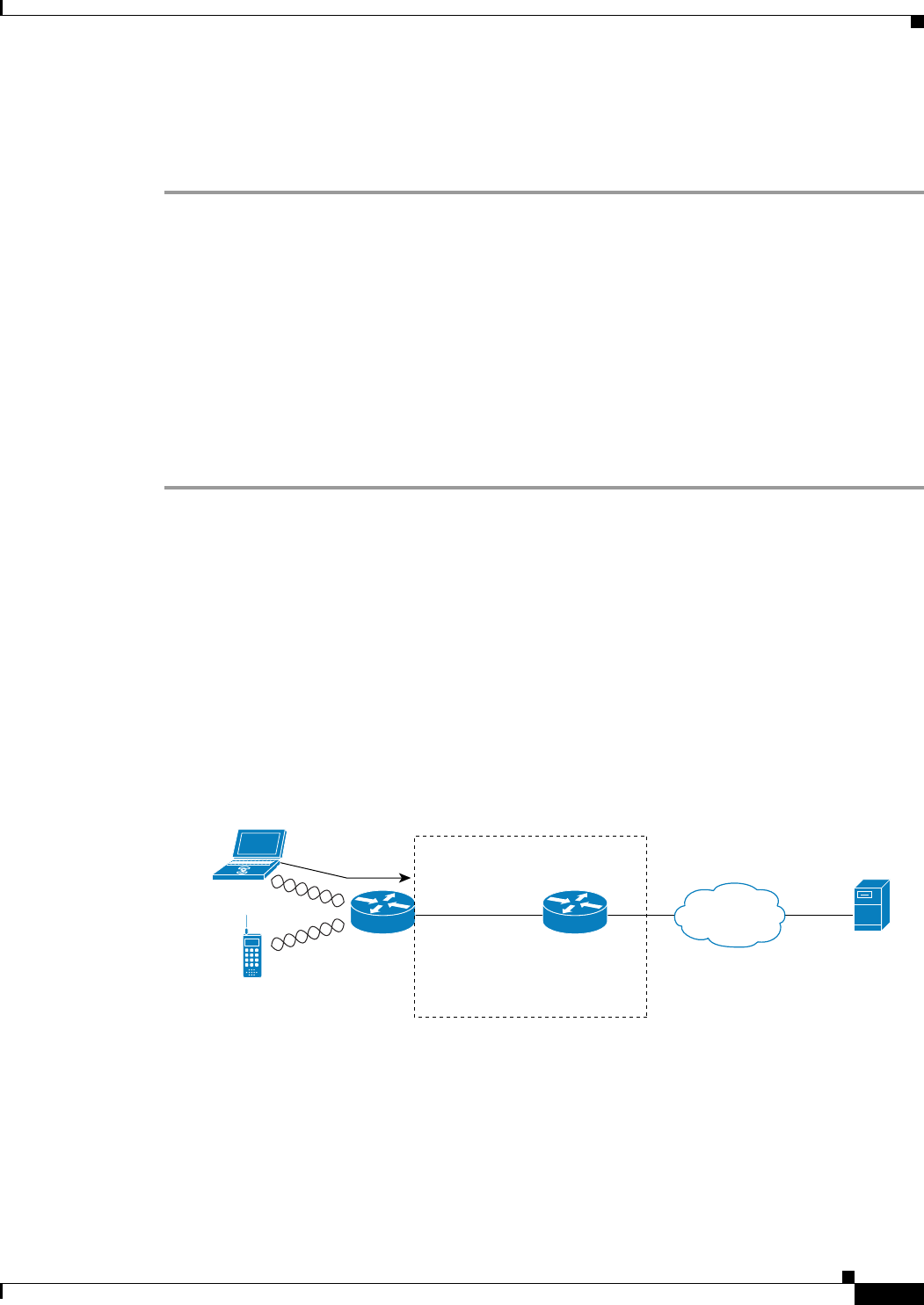
6-59
Cisco Wireless LAN Controller Configuration Guide
OL-21524-02
Chapter 6 Configuring Security Solutions
Configuring DHCP Option 82
Using the CLI to Enable Management over Wireless
To enable management over wireless using the controller CLI, follow these steps:
Step 1 Verify whether the management over wireless interface is enabled or disabled by entering this command:
show network summary
If disabled, continue with Step 2. Otherwise, continue with Step 3.
Step 2 Enable management over wireless by entering this command:
config network mgmt-via-wireless enable
Step 3 Use a wireless client to associate with an access point connected to the controller that you want to
manage.
Step 4 Log into the CLI to verify that you can manage the WLAN using a wireless client by entering this
command:
telnet controller-ip-address command
Configuring DHCP Option 82
DHCP option 82 provides additional security when DHCP is used to allocate network addresses.
Specifically, it enables the controller to act as a DHCP relay agent to prevent DHCP client requests from
untrusted sources. The controller can be configured to add option 82 information to DHCP requests from
clients before forwarding the requests to the DHCP server. See Figure 6-28 for an illustration of this
process.
Figure 6-28 DHCP Option 82
The access point forwards all DHCP requests from a client to the controller. The controller adds the
DHCP option 82 payload and forwards the request to the DHCP server. The payload can contain the
MAC address or the MAC address and SSID of the access point, depending on how you configure this
option. In controller software release 4.0 or later releases, you can configure DHCP option 82 using the
controller CLI. In controller software release 6.0 or later releases, you can configure this feature using
either the GUI or CLI.
PC or PDA with 802.11
Client and IP Soft-Phone
802.11 WLAN
IP Phone
Controller adds Option 82
payload to the request
and forwards it to DHCP Server
Access
Point DHCP
Relay Agent
(Controller)
IP
DHCP
Server
231050
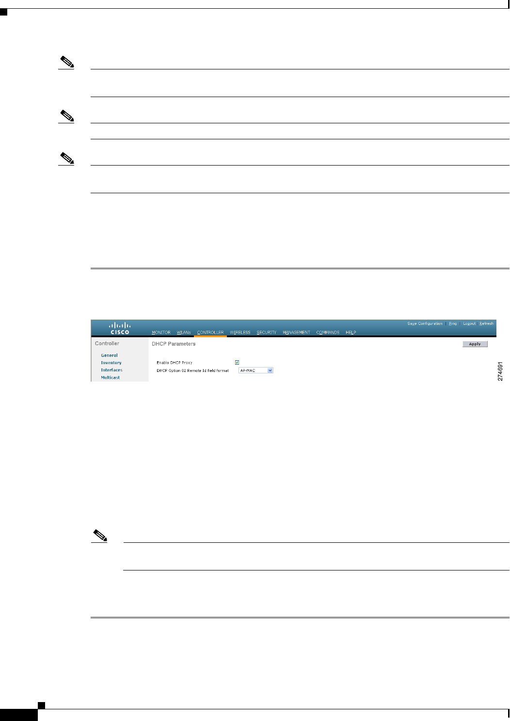
6-60
Cisco Wireless LAN Controller Configuration Guide
OL-21524-02
Chapter 6 Configuring Security Solutions
Configuring DHCP Option 82
Note In order for DHCP option 82 to operate correctly, DHCP proxy must be enabled. See the “Configuring
DHCP Proxy” section on page 4-39 for instructions on configuring DHCP proxy.
Note Any DHCP packets that already include a relay agent option are dropped at the controller.
Note DHCP option 82 is not supported for use with auto-anchor mobility, which is described in Chapter 14,
“Configuring Mobility Groups.”
Using the GUI to Configure DHCP Option 82
To configure DHCP option 82 using the controller GUI, follow these steps:
Step 1 Choose Controller > Advanced > DHCP to open the DHCP Parameters page (see Figure 6-29).
Figure 6-29 DHCP Parameters Page
Step 2 Select the Enable DHCP Proxy check box to enable DHCP proxy.
Step 3 Choose one of the following options from the DHCP Option 82 Remote ID text box Format drop-down
list to specify the format of the DHCP option 82 payload:
• AP-MAC—Adds the MAC address of the access point to the DHCP option 82 payload. This is the
default value.
• AP-MAC-SSID—Adds the MAC address and SSID of the access point to the DHCP option 82
payload.
• AP-ETHMAC—Adds the Ethernet MAC address of the access point to the DHCP option 82
payload.
Note If the SSID is associated with a dynamic interface, then the DHCP Option 82 that you configure
must be enabled on the dynamic interface.
Step 4 Click Apply to commit your changes.
Step 5 Click Save Configuration to save your changes.

6-61
Cisco Wireless LAN Controller Configuration Guide
OL-21524-02
Chapter 6 Configuring Security Solutions
Configuring and Applying Access Control Lists
Using the CLI to Configure DHCP Option 82
To configure DHCP option 82 using the controller CLI, use these commands:
• Configure the format of the DHCP option 82 payload by entering one of these commands:
–
config dhcp opt-82 remote-id ap_mac
This command adds the MAC address of the access point to the DHCP option 82 payload.
–
config dhcp opt-82 remote-id ap_mac:ssid
This command adds the MAC address and SSID of the access point to the DHCP option 82
payload.
–
config dhcp opt-82 remote-id ap-ethmac
Adds the Ethernet MAC address of the access point to the DHCP option 82 payload.
• Override the global DHCP option 82 setting and disable (or enable) this feature for the AP-manager
or management interface on the controller by entering this command:
config interface dhcp {ap-manager | management} option-82 {disable | enable}
• See the status of DHCP option 82 on the controller by entering this command:
show interface detailed ap-manager
Information similar to the following appears:
Interface Name................................... ap-manager
MAC Address...................................... 00:0a:88:25:10:c4
IP Address....................................... 10.30.16.13
IP Netmask....................................... 255.255.248.0
IP Gateway....................................... 10.30.16.1
External NAT IP State............................ Disabled
External NAT IP Address.......................... 0.0.0.0
External NAT IP Netmask.......................... 0.0.0.0
VLAN............................................. untagged
Active Physical Port............................. LAG (29)
Primary Physical Port............................ LAG (29)
Backup Physical Port............................. Unconfigured
Primary DHCP Server.............................. 10.1.0.10
Secondary DHCP Server............................ Unconfigured
DHCP Option 82................................... Enabled
ACL.............................................. Unconfigured
AP Manager....................................... Yes
Guest Interface.................................. No
Configuring and Applying Access Control Lists
An access control list (ACL) is a set of rules used to limit access to a particular interface (for example,
if you want to restrict a wireless client from pinging the management interface of the controller). After
ACLs are configured on the controller, they can be applied to the management interface, the AP-manager
interface, any of the dynamic interfaces, or a WLAN to control data traffic to and from wireless clients
or to the controller central processing unit (CPU) to control all traffic destined for the CPU.
You may also want to create a preauthentication ACL for web authentication. Such an ACL could be used
to allow certain types of traffic before authentication is complete.
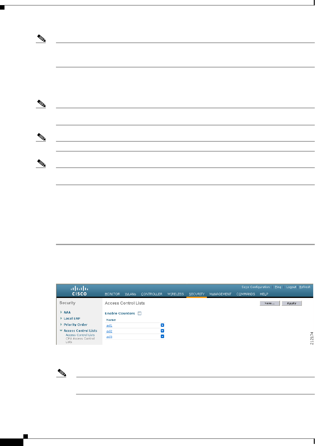
6-62
Cisco Wireless LAN Controller Configuration Guide
OL-21524-02
Chapter 6 Configuring Security Solutions
Configuring and Applying Access Control Lists
Note If you are using an external web server with a Cisco 5500 Series Controller, a Cisco 2100 Series
Controller, or a controller network module, you must configure a preauthentication ACL on the WLAN
for the external web server.
You can define up to 64 ACLs, each with up to 64 rules (or filters). Each rule has parameters that affect
its action. When a packet matches all of the parameters for a rule, the action set for that rule is applied
to the packet.
Note All ACLs have an implicit “deny all rule” as the last rule. If a packet does not match any of the rules, it
is dropped by the controller.
Note ACLs in your network might need to be modified if CAPWAP uses different ports than LWAPP.
Note Adding an ACL on the Controller results in the degradation of throughput and could even result in packet
loss.
You can configure and apply ACLs through either the GUI or the CLI.
Using the GUI to Configure Access Control Lists
To configure ACLs using the controller GUI, follow these steps:
Step 1 Choose Security > Access Control Lists > Access Control Lists to open the Access Control Lists page
(see Figure 6-30).
Figure 6-30 Access Control Lists Page
This page lists all of the ACLs that have been configured for this controller.
Note If you want to delete an existing ACL, hover your cursor over the blue drop-down arrow for that
ACL and choose Remove.
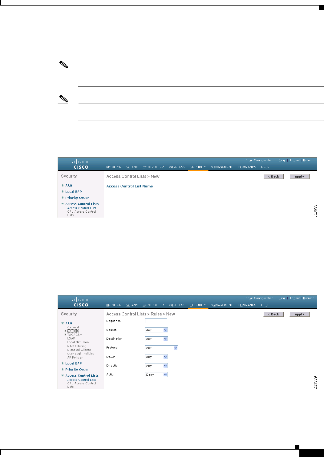
6-63
Cisco Wireless LAN Controller Configuration Guide
OL-21524-02
Chapter 6 Configuring Security Solutions
Configuring and Applying Access Control Lists
Step 2 If you want to see if packets are hitting any of the ACLs configured on your controller, select the Enable
Counters check box and click Apply. Otherwise, leave the check box unselected, which is the default
value. This feature is useful when troubleshooting your system.
Note If you want to clear the counters for an ACL, hover your cursor over the blue drop-down arrow
for that ACL and choose Clear Counters.
Note ACL counters are available only on the following controllers: 5500 series, 4400 series, Cisco
WiSM, and Catalyst 3750G Integrated Wireless LAN Controller Switch.
Step 3 Add a new ACL by clicking New. The Access Control Lists > New page appears (see Figure 6-31).
Figure 6-31 Access Control Lists > New Page
Step 4 In the Access Control List Name text box, enter a name for the new ACL. You can enter up to 32
alphanumeric characters.
Step 5 Click Apply. When the Access Control Lists page reappears, click the name of the new ACL.
Step 6 When the Access Control Lists > Edit page appears, click Add New Rule. The Access Control Lists >
Rules > New page appears (see Figure 6-32).
Figure 6-32 Access Control Lists > Rules > New Page

6-64
Cisco Wireless LAN Controller Configuration Guide
OL-21524-02
Chapter 6 Configuring Security Solutions
Configuring and Applying Access Control Lists
Step 7 Configure a rule for this ACL as follows:
a. The controller supports up to 64 rules for each ACL. These rules are listed in order from 1 to 64. In
the Sequence text box, enter a value (between 1 and 64) to determine the order of this rule in relation
to any other rules defined for this ACL.
Note If rules 1 through 4 are already defined and you add rule 29, it is added as rule 5. If you add
or change a sequence number for a rule, the sequence numbers for other rules adjust to
maintain a contiguous sequence. For instance, if you change a rule’s sequence number from
7 to 5, the rules with sequence numbers 5 and 6 are automatically reassigned as 6 and 7,
respectively.
b. From the Source drop-down list, choose one of these options to specify the source of the packets to
which this ACL applies:
• Any—Any source (this is the default value).
• IP Address—A specific source. If you choose this option, enter the IP address and netmask of
the source in the edit boxes.
c. From the Destination drop-down list, choose one of these options to specify the destination of the
packets to which this ACL applies:
• Any—Any destination (this is the default value).
• IP Address—A specific destination. If you choose this option, enter the IP address and netmask
of the destination in the edit boxes.
d. From the Protocol drop-down list, choose the protocol ID of the IP packets to be used for this ACL.
These are the protocol options:
• Any—Any protocol (this is the default value)
• TCP—Transmission Control Protocol
• UDP—User Datagram Protocol
• ICMP—Internet Control Message Protocol
• ESP—IP Encapsulating Security Payload
• AH—Authentication Header
• GRE—Generic Routing Encapsulation
• IP in IP—Internet Protocol (IP) in IP (permits or denies IP-in-IP packets)
• Eth Over IP—Ethernet-over-Internet Protocol
• OSPF—Open Shortest Path First
• Other—Any other Internet Assigned Numbers Authority (IANA) protocol
Note If you choose Other, enter the number of the desired protocol in the Protocol text box.
You can find the list of available protocols in the INAI wesite.
• The controller can permit or deny only IP packets in an ACL. Other types of packets (such as ARP
packets) cannot be specified.
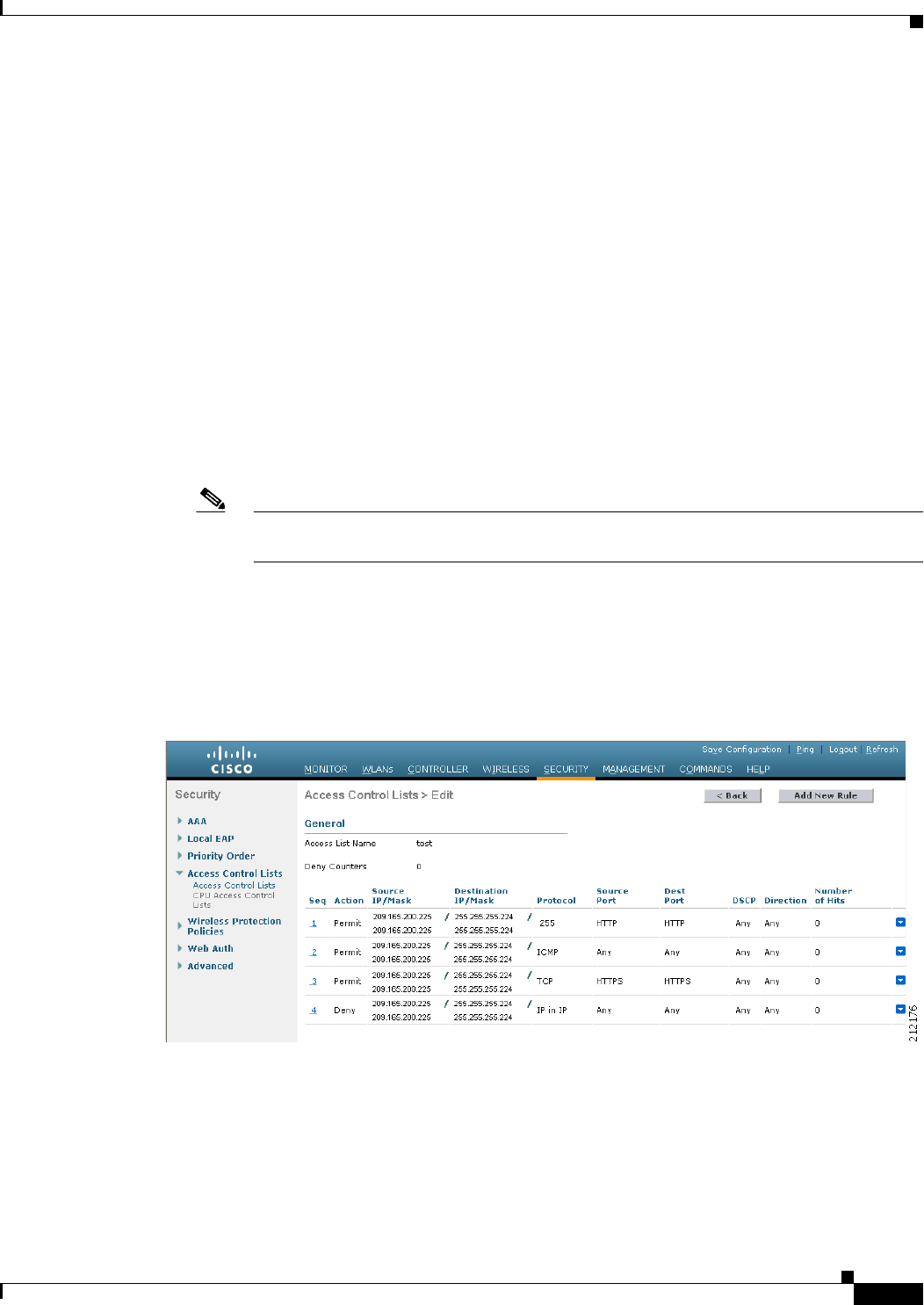
6-65
Cisco Wireless LAN Controller Configuration Guide
OL-21524-02
Chapter 6 Configuring Security Solutions
Configuring and Applying Access Control Lists
e. If you chose TCP or UDP in the previous step, two additional parameters appear: Source Port and
Destination Port. These parameters enable you to choose a specific source port and destination port
or port ranges. The port options are used by applications that send and receive data to and from the
networking stack. Some ports are designated for certain applications such as telnet, ssh, http, and so
on.
f. From the DSCP drop-down list, choose one of these options to specify the differentiated services
code point (DSCP) value of this ACL. DSCP is an IP header text box that can be used to define the
quality of service across the Internet.
• Any—Any DSCP (this is the default value)
• Specific—A specific DSCP from 0 to 63, which you enter in the DSCP edit box
g. From the Direction drop-down list, choose one of these options to specify the direction of the traffic
to which this ACL applies:
• Any—Any direction (this is the default value)
• Inbound—From the client
• Outbound—To the client
Note If you are planning to apply this ACL to the controller CPU, the packet direction does not
have any significance, it is always ‘Any’.
h. From the Action drop-down list, choose Deny to cause this ACL to block packets or Permit to cause
this ACL to allow packets. The default value is Deny.
i. Click Apply to commit your changes. The Access Control Lists > Edit page reappears, showing the
rules for this ACL. See Figure 6-33.
Figure 6-33 Access Control Lists > Edit Page
The Deny Counters fields shows the number of times that packets have matched the explicit deny
ACL rule. The Number of Hits field shows the number of times that packets have matched an ACL
rule. You must enable ACL counters on the Access Control Lists page to enable these fields.

6-66
Cisco Wireless LAN Controller Configuration Guide
OL-21524-02
Chapter 6 Configuring Security Solutions
Configuring and Applying Access Control Lists
Note If you want to edit a rule, click the sequence number of the desired rule to open the Access
Control Lists > Rules > Edit page. If you want to delete a rule, hover your cursor over the
blue drop-down arrow for the desired rule and choose Remove.
j. Repeat this procedure to add any additional rules for this ACL.
Step 8 Click Save Configuration to save your changes.
Step 9 Repeat this procedure to add any additional ACLs.
Using the GUI to Apply Access Control Lists
These sections describe how to apply ACLs using the controller GUI:
• Applying an Access Control List to an Interface, page 6-66
• Applying an Access Control List to the Controller CPU, page 6-67
• Applying an Access Control List to a WLAN, page 6-68
• Applying a Preauthentication Access Control List to a WLAN, page 6-69
Note If you apply an ACL to an interface or a WLAN, wireless throughput is degraded when downloading
from a 1-Gbps file server. To improve throughput, remove the ACL from the interface or WLAN, move
the ACL to a neighboring wired device with a policy rate-limiting restriction, or connect the file server
using 100 Mbps rather than 1 Gbps.
Applying an Access Control List to an Interface
To apply an ACL to a management, AP-manager, or dynamic interface using the controller GUI, follow
these steps:
Step 1 Choose Controller > Interfaces.
Step 2 Click the name of the desired interface. The Interfaces > Edit page for that interface appears (see
Figure 6-34).
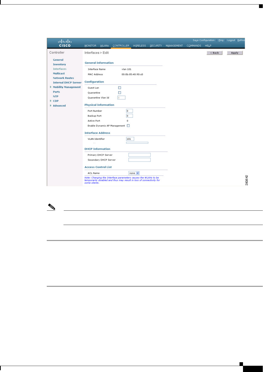
6-67
Cisco Wireless LAN Controller Configuration Guide
OL-21524-02
Chapter 6 Configuring Security Solutions
Configuring and Applying Access Control Lists
Figure 6-34 Interfaces > Edit Page
Step 3 Choose the desired ACL from the ACL Name drop-down list and click Apply. None is the default value.
Note See Chapter 3, “Configuring Ports and Interfaces,” for more information on configuring
controller interfaces.
Step 4 Click Save Configuration to save your changes.
Applying an Access Control List to the Controller CPU
To apply an ACL to the controller CPU to control traffic to the CPU using the controller GUI, follow
these steps:
Step 1 Choose Security > Access Control Lists > CPU Access Control Lists to open the CPU Access Control
Lists page (see Figure 6-35).

6-68
Cisco Wireless LAN Controller Configuration Guide
OL-21524-02
Chapter 6 Configuring Security Solutions
Configuring and Applying Access Control Lists
Figure 6-35 CPU Access Control Lists Page
Step 2 Select the Enable CPU ACL check box to enable a designated ACL to control the traffic to the controller
CPU or unselect the check box to disable the CPU ACL feature and remove any ACL that had been
applied to the CPU. The default value is unselected.
Step 3 From the ACL Name drop-down list, choose the ACL that will control the traffic to the controller CPU.
None is the default value when the CPU ACL feature is disabled. If you choose None while the CPU
ACL Enable check box is selected, an error message appears indicating that you must choose an ACL.
Note This parameter is available only if you have selected the CPU ACL Enable check box.
Note When CPU ACL is enabled, it is applicable to both wireless and wired traffic.
Step 4 Click Apply to commit your changes.
Step 5 Click Save Configuration to save your changes.
Applying an Access Control List to a WLAN
To apply an ACL to a WLAN using the controller GUI, follow these steps:
Step 1 Choose WLANs to open the WLANs page.
Step 2 Click the ID number of the desired WLAN to open the WLANs > Edit page.
Step 3 Choose the Advanced tab to open the WLANs > Edit (Advanced) page (see Figure 6-36).
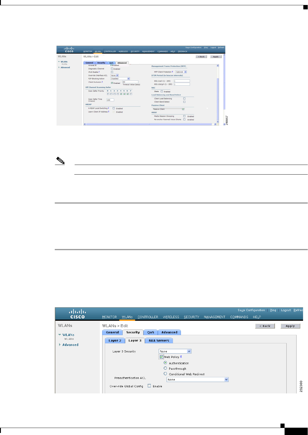
6-69
Cisco Wireless LAN Controller Configuration Guide
OL-21524-02
Chapter 6 Configuring Security Solutions
Configuring and Applying Access Control Lists
Figure 6-36 WLANs > Edit (Advanced) Page
Step 4 From the Override Interface ACL drop-down list, choose the ACL that you want to apply to this WLAN.
The ACL that you choose overrides any ACL that is configured for the interface. None is the default
value.
Note See Chapter 7, “Configuring WLANs,” for more information on configuring WLANs.
Step 5 Click Apply to commit your changes.
Step 6 Click Save Configuration to save your changes.
Applying a Preauthentication Access Control List to a WLAN
To apply a preauthentication ACL to a WLAN using the controller GUI, follow these steps:
Step 1 Choose WLANs to open the WLANs page.
Step 2 Click the ID number of the desired WLAN to open the WLANs > Edit page.
Step 3 Choose the Security and Layer 3 tabs to open the WLANs > Edit (Security > Layer 3) page (see
Figure 6-37).
Figure 6-37 WLANs > Edit (Security > Layer 3) Page
Step 4 Select the Web Policy check box.

6-70
Cisco Wireless LAN Controller Configuration Guide
OL-21524-02
Chapter 6 Configuring Security Solutions
Configuring and Applying Access Control Lists
Step 5 From the Preauthentication ACL drop-down list, choose the desired ACL and click Apply. None is the
default value.
Note See Chapter 7, “Configuring WLANs” for more information on configuring WLANs.
Step 6 Click Save Configuration to save your changes.
Using the CLI to Configure Access Control Lists
To configure ACLs using the controller CLI, follow these steps:
Step 1 See all of the ACLs that are configured on the controller by entering this command:
show acl summary
Information similar to the following appears:
ACL Counter Status Enabled
-------------------------------------
ACL Name Applied
------------------------- -----------
acl1 Yes
acl2 Yes
acl3 Yes
Step 2 See detailed information for a particular ACL by entering this command:
show acl detailed acl_name
Information similar to the following appears:
Source Destination Source Port Dest Port
I Dir IP Address/Netmask IP Address/Netmask Prot Range Range DSCP Action Counter
- --- ------------------ ------------------ ---- ----------- -------- ----- ------ -------
1 Any 0.0.0.0/0.0.0.0 0.0.0.0/0.0.0.0 Any 0-65535 0-65535 0 Deny 0
2 In 0.0.0.0/0.0.0.0 200.200.200.0/ 6 80-80 0-65535 Any Permit 0
255.255.255.0
DenyCounter : 0
The Counter text box increments each time a packet matches an ACL rule, and the DenyCounter text box
increments each time a packet does not match any of the rules.
Step 3 Enable or disable ACL counters for your controller by entering this command:
config acl counter {start | stop}
Note If you want to clear the current counters for an ACL, enter the clear acl counters acl_name
command.
Note ACL counters are available only on the Cisco 5500 Series Controller, Cisco 4400 Series
Controller, Cisco WiSM, and Catalyst 3750G Integrated Wireless LAN Controller Switch.

6-71
Cisco Wireless LAN Controller Configuration Guide
OL-21524-02
Chapter 6 Configuring Security Solutions
Configuring and Applying Access Control Lists
Step 4 Add a new ACL by entering this command:
config acl create acl_name
You can enter up to 32 alphanumeric characters for the acl_name parameter.
Note When you try to create an interface name with space, the controller CLI does not create an interface. For
example, if you want to create an interface name int 3, the CLI will not create this since there is a space
between int and 3. If you want to use int 3 as the interface name, you need to enclose within single quotes
like ‘int 3’.
Step 5 Add a rule for an ACL by entering this command:
config acl rule add acl_name rule_index
Step 6 Configure an ACL rule by entering this command:
config acl rule
action acl_name rule_index {permit | deny} |
change index acl_name old_index new_index |
destination address acl_name rule_index ip_address netmask |
destination port range acl_name rule_index start_port end_port |
direction acl_name rule_index {in | out | any} |
dscp acl_name rule_index dscp |
protocol acl_name rule_index protocol |
source address acl_name rule_index ip_address netmask |
source port range acl_name rule_index start_port end_port |
swap index acl_name index_1 index_2}
See Step 7 of the “Using the GUI to Configure Access Control Lists” section on page 6-62 for
explanations of the rule parameters.
Step 7 Save your settings by entering this command:
save config
Note To delete an ACL, enter the config acl delete acl_name command. To delete an ACL rule, enter
the config acl rule delete acl_name rule_index command.
Using the CLI to Apply Access Control Lists
To apply ACLs using the controller CLI, follow these steps:
Step 1 Perform any of the following:
• To apply an ACL to a management, AP-manager, or dynamic interface, enter this command:
config interface acl {management | ap-manager | dynamic_interface_name} acl_name

6-72
Cisco Wireless LAN Controller Configuration Guide
OL-21524-02
Chapter 6 Configuring Security Solutions
Configuring Management Frame Protection
Note To see the ACL that is applied to an interface, enter the show interface detailed
{management | ap-manager | dynamic_interface_name} command. To remove an ACL that
is applied to an interface, enter the config interface acl
{management | ap-manager | dynamic_interface_name} none command.
See Chapter 3, “Configuring Ports and Interfaces,” for more information on configuring controller
interfaces.
• To apply an ACL to the data path, enter this command:
config acl apply acl_name
• To apply an ACL to the controller CPU to restrict the type of traffic (wired, wireless, or both)
reaching the CPU, enter this command:
config acl cpu acl_name {wired | wireless | both}
Note To see the ACL that is applied to the controller CPU, enter the show acl cpu command. To
remove the ACL that is applied to the controller CPU, enter the config acl cpu none
command.
• To apply an ACL to a WLAN, enter this command:
config wlan acl wlan_id acl_name
Note To see the ACL that is applied to a WLAN, enter the show wlan wlan_id command. To
remove the ACL that is applied to a WLAN, enter the config wlan acl wlan_id none
command.
• To apply a preauthentication ACL to a WLAN, enter this command:
config wlan security web-auth acl wlan_id acl_name
See Chapter 7, “Configuring WLANs,” for more information on configuring WLANs.
Step 2 Save your changes by entering this command:
save config
Configuring Management Frame Protection
Management frame protection (MFP) provides security for the otherwise unprotected and unencrypted
802.11 management messages passed between access points and clients. MFP provides both
infrastructure and client support. Controller software release 4.1 or later releases support both
infrastructure and client MFP while controller software release 4.0 supports only infrastructure MFP.
• Infrastructure MFP—Protects management frames by detecting adversaries that are invoking
denial-of-service attacks, flooding the network with associations and probes, interjecting as rogue
access points, and affecting network performance by attacking the QoS and radio measurement
frames. It also provides a quick and effective means to detect and report phishing incidents.

6-73
Cisco Wireless LAN Controller Configuration Guide
OL-21524-02
Chapter 6 Configuring Security Solutions
Configuring Management Frame Protection
Specifically, infrastructure MFP protects 802.11 session management functions by adding message
integrity check information elements (MIC IEs) to the management frames emitted by access points
(and not those emitted by clients), which are then validated by other access points in the network.
Infrastructure MFP is passive. It can detect and report intrusions but has no means to stop them.
• Client MFP—Shields authenticated clients from spoofed frames, preventing many of the common
attacks against wireless LANs from becoming effective. Most attacks, such as deauthentication
attacks, revert to simply degrading performance by contending with valid clients.
Specifically, client MFP encrypts management frames are sent between access points and CCXv5
clients so that both the access points and clients can take preventative action by dropping spoofed
class 3 management frames (that is, management frames passed between an access point and a client
that is authenticated and associated). Client MFP leverages the security mechanisms defined by
IEEE 802.11i to protect the following types of class 3 unicast management frames: disassociation,
deauthentication, and QoS (WMM) action. Client MFP protects a client-access point session from
the most common type of denial-of-service attack. It protects class 3 management frames by using
the same encryption method used for the session’s data frames. If a frame received by the access
point or client fails decryption, it is dropped, and the event is reported to the controller.
To use client MFP, clients must support CCXv5 MFP and must negotiate WPA2 using either TKIP
or AES-CCMP. EAP or PSK may be used to obtain the PMK. CCKM and controller mobility
management are used to distribute session keys between access points for Layer 2 and Layer 3 fast
roaming.
Note To prevent attacks using broadcast frames, access points supporting CCXv5 will not emit any
broadcast class 3 management frames (such as disassociation, deauthentication, or action).
CCXv5 clients and access points must discard broadcast class 3 management frames.
Client MFP supplements infrastructure MFP rather than replaces it because infrastructure MFP
continues to detect and report invalid unicast frames sent to clients that are not client-MFP capable
as well as invalid class 1 and 2 management frames. Infrastructure MFP is applied only to
management frames that are not protected by client MFP.
Infrastructure MFP consists of three main components:
• Management frame protection—The access point protects the management frames it transmits by
adding a MIC IE to each frame. Any attempt to copy, alter, or replay the frame invalidates the MIC,
causing any receiving access point configured to detect MFP frames to report the discrepancy.
• Management frame validation—In infrastructure MFP, the access point validates every management
frame that it receives from other access points in the network. It ensures that the MIC IE is present
(when the originator is configured to transmit MFP frames) and matches the content of the
management frame. If it receives any frame that does not contain a valid MIC IE from a BSSID
belonging to an access point that is configured to transmit MFP frames, it reports the discrepancy to
the network management system. In order for the timestamps to operate properly, all controllers
must be Network Transfer Protocol (NTP) synchronized.
• Event reporting—The access point notifies the controller when it detects an anomaly, and the
controller aggregates the received anomaly events and can report the results through SNMP traps to
the network management system.
Note Error reports generated on a hybrid-REAP access point in standalone mode cannot be
forwarded to the controller and are dropped.

6-74
Cisco Wireless LAN Controller Configuration Guide
OL-21524-02
Chapter 6 Configuring Security Solutions
Using the GUI to Configure MFP
Note Client MFP uses the same event reporting mechanisms as infrastructure MFP.
Infrastructure MFP is enabled by default and can be disabled globally. When you upgrade from a
previous software release, infrastructure MFP is disabled globally if access point authentication is
enabled because the two features are mutually exclusive. Once infrastructure MFP is enabled globally,
signature generation (adding MICs to outbound frames) can be disabled for selected WLANs, and
validation can be disabled for selected access points.
Client MFP is enabled by default on WLANs that are configured for WPA2. It can be disabled, or it can
be made mandatory (in which case, only clients that negotiate MFP are allowed to associate) on selected
WLANs.
Note Infrastructure MFP is a global setting only in the 7.0.98.0 release. In the earlier releases, there was an
option for you to enable or disable the MFP infrastructure protection for WLANs and MFP infrastructure
validation for APs. These options are no longer available in the GUI or CLI.
Guidelines for Using MFP
Follow these guidelines for using MFP:
• MFP is supported for use with Cisco Aironet lightweight access points.
• Lightweight access points support infrastructure MFP in local and monitor modes and in
hybrid-REAP mode when the access point is connected to a controller. They support client MFP in
local, hybrid-REAP, and bridge modes.
Note OEAP 600 Series Access points do not support MFP.
• Client MFP is supported for use only with CCXv5 clients using WPA2 with TKIP or AES-CCMP.
• Non-CCXv5 clients may associate to a WLAN if client MFP is disabled or optional.
Using the GUI to Configure MFP
To configure MFP using the controller GUI, follow these steps:
Step 1 Choose Security > Wireless Protection Policies > AP Authentication/MFP to open the AP
Authentication Policy page (see Figure 6-38).
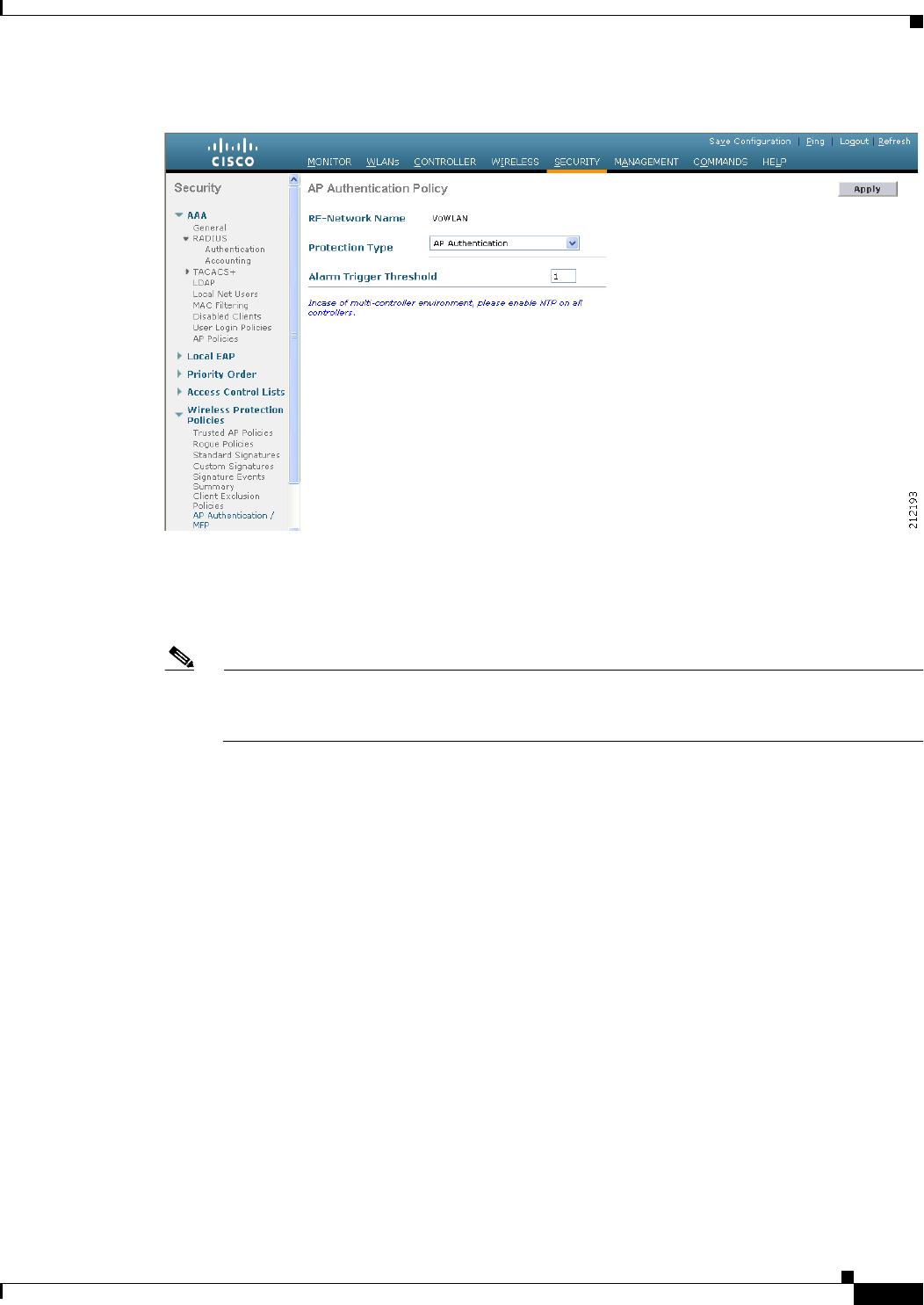
6-75
Cisco Wireless LAN Controller Configuration Guide
OL-21524-02
Chapter 6 Configuring Security Solutions
Using the GUI to Configure MFP
Figure 6-38 AP Authentication Policy Page
Step 2 Enable infrastructure MFP globally for the controller by choosing Management Frame Protection
from the Protection Type drop-down list.
Step 3 Click Apply to commit your changes.
Note If more than one controller is included in the mobility group, you must configure a Network
Time Protocol (NTP) server on all controllers in the mobility group that are configured for
infrastructure MFP.
Step 4 Configure client MFP for a particular WLAN after infrastructure MFP has been enabled globally for the
controller as follows:
a. Choose WLANs.
b. Click the profile name of the desired WLAN. The WLANs > Edit page appears.
c. Choose Advanced. The WLANs > Edit (Advanced) page appears (see Figure 6-39).
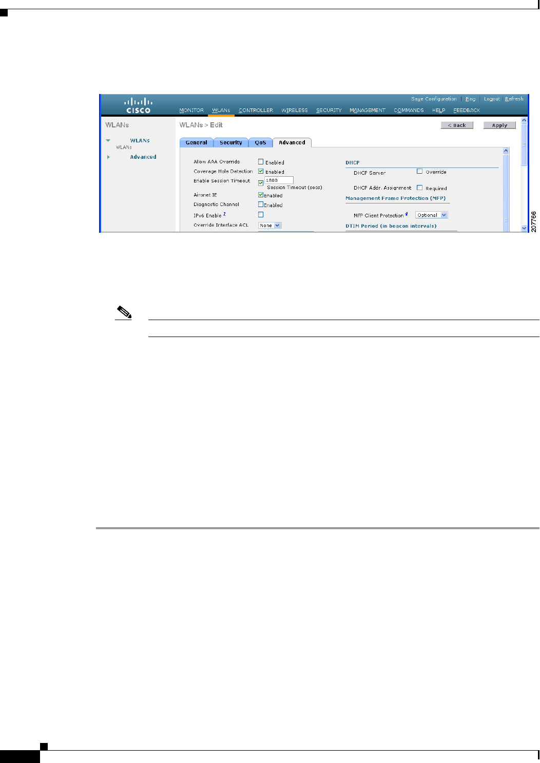
6-76
Cisco Wireless LAN Controller Configuration Guide
OL-21524-02
Chapter 6 Configuring Security Solutions
Using the GUI to Configure MFP
Figure 6-39 WLANs > Edit (Advanced) Page
d. Choose Disabled, Optional, or Required from the MFP Client Protection drop-down list. The
default value is Optional. If you choose Required, clients are allowed to associate only if MFP is
negotiated (that is, if WPA2 is configured on the controller and the client supports CCXv5 MFP and
is also configured for WPA2).
Note For Cisco OEAP 600, MFP is not supported. It should either be Disabled or Optional.
e. Click Apply to commit your changes.
Step 5 Disable or reenable infrastructure MFP validation for a particular access point after infrastructure MFP
has been enabled globally for the controller as follows:
a. Choose Wireless > Access Points > All APs to open the All APs page.
b. Click the name of the desired access point.
c. Choose the Advanced tab. The All APs > Details for (Advanced) page appears.
d. Unselect the MFP Frame Validation check box to disable MFP for this access point or select this
check box to enable MFP for this access point. The default value is enabled. If global MFP is
disabled, a note appears in parentheses to the right of the check box.
e. Click Apply to commit your changes.
Step 6 Click Save Configuration to save your settings.
Using the GUI to View MFP Settings
To see the controller’s current global MFP settings, choose Security > Wireless Protection Policies >
Management Frame Protection. The Management Frame Protection Settings page appears (see
Figure 6-40).
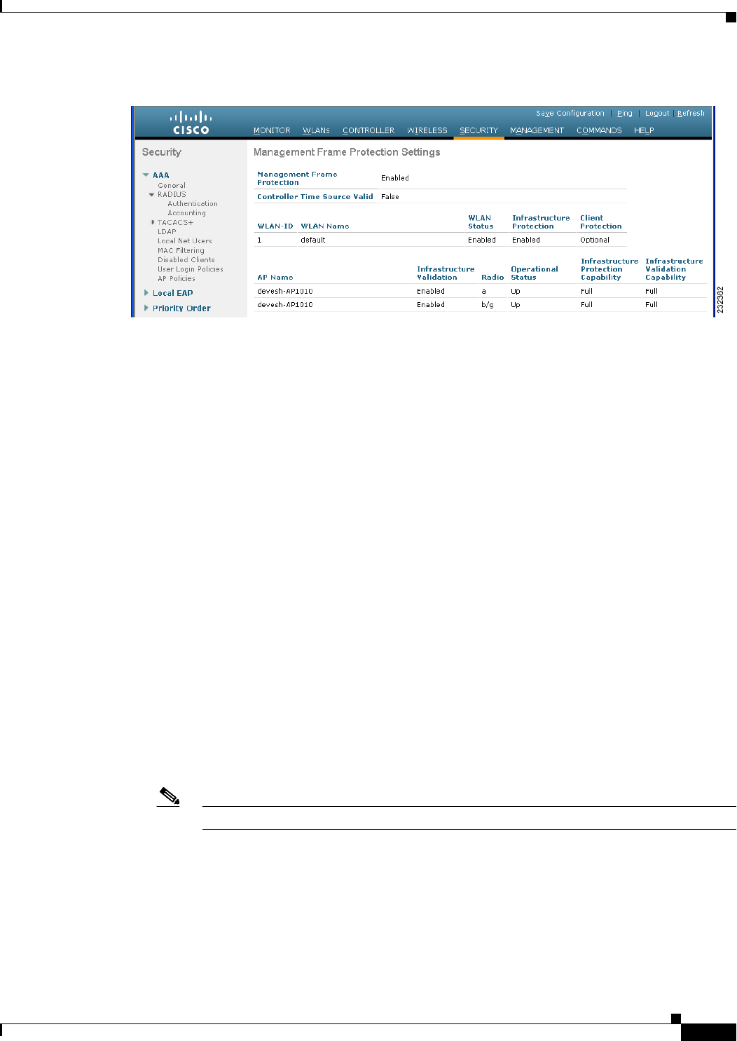
6-77
Cisco Wireless LAN Controller Configuration Guide
OL-21524-02
Chapter 6 Configuring Security Solutions
Using the GUI to Configure MFP
Figure 6-40 Management Frame Protection Settings Page
On this page, you can see the following MFP settings:
• The Management Frame Protection field shows if infrastructure MFP is enabled globally for the
controller.
• The Controller Time Source Valid field indicates whether the controller time is set locally (by
manually entering the time) or through an external source (such as the NTP server). If the time is set
by an external source, the value of this field is “True.” If the time is set locally, the value is “False.”
The time source is used for validating the timestamp on management frames between access points
of different controllers within a mobility group.
• The Infrastructure Protection field shows if infrastructure MFP is enabled for individual WLANs.
• The Client Protection field shows if client MFP is enabled for individual WLANs and whether it is
optional or required.
• The Infrastructure Validation text box shows if infrastructure MFP is enabled for individual access
points.
Using the CLI to Configure MFP
To configure MFP using the controller CLI, use these commands:
• Enable or disable infrastructure MFP globally for the controller by entering this command:
config wps mfp infrastructure {enable | disable}
• Enable or disable infrastructure MFP validation on an access point by entering this command:
config ap mfp infrastructure validation {enable | disable} Cisco_AP
Note MFP validation is activated only if infrastructure MFP is globally enabled.
• Enable or disable client MFP on a specific WLAN by entering this command:
config wlan mfp client {enable | disable} wlan_id [required]
If you enable client MFP and use the optional required parameter, clients are allowed to associate
only if MFP is negotiated.

6-78
Cisco Wireless LAN Controller Configuration Guide
OL-21524-02
Chapter 6 Configuring Security Solutions
Using the GUI to Configure MFP
Using the CLI to View MFP Settings
To view MFP settings using the controller CLI, use these commands:
• See the controller’s current MFP settings by entering this command:
show wps mfp summary
Information similar to the following appears:
Global Infrastructure MFP state.... Enabled
Controller Time Source Valid....... False
WLAN Infra. Client
WLAN ID WLAN Name Status Protection Protection
------- ---------- -------- ---------- -----------
1 test1 Enabled Disabled Disabled
2 open Enabled Enabled Required
3 testpsk Enabled *Enabled Optional but inactive (WPA2 not configured)
Infra. Operational --Infra. Capability--
AP Name Validation Radio State Protection Validation
-------- ----------- ----- ----------- ----------- -----------
mapAP Disabled a Up Full Full
b/g Up Full Full
rootAP2 Enabled a Up Full Full
b/g Up Full Full
HReap *Enabled b/g Up Full Full
a Down Full Full
• See the current MFP configuration for a particular WLAN by entering this command:
show wlan wlan_id
Information similar to the following appears:
WLAN Identifier........................... 1
Profile Name.............................. test1
Network Name (SSID)....................... test1
Status.................................... Enabled
MAC Filtering............................. Disabled
Broadcast SSID............................ Enabled
...
Local EAP Authentication.................. Enabled (Profile 'test')
Diagnostics Channel....................... Disabled
Security
802.11 Authentication:................. Open System
Static WEP Keys........................ Disabled
802.1X................................. Enabled
Encryption:.............................. 104-bit WEP
Wi-Fi Protected Access (WPA/WPA2)...... Disabled
CKIP .................................. Disabled
IP Security............................ Disabled
IP Security Passthru................... Disabled
Web Based Authentication............... Disabled
Web-Passthrough........................ Disabled
Conditional Web Redirect............... Disabled
Auto Anchor............................ Enabled
H-REAP Local Switching................. Disabled
Infrastructure MFP protection.......... Enabled
Client MFP............................. Required
...
• See the current MFP configuration for a particular access point by entering this command:

6-79
Cisco Wireless LAN Controller Configuration Guide
OL-21524-02
Chapter 6 Configuring Security Solutions
Using the GUI to Configure MFP
show ap config general ap_name
Information similar to the following appears:
Cisco AP Identifier.............................. 0
Cisco AP Name.................................... ap:52:c5:c0
AP Regulatory Domain............................. 80211bg: -N 80211a: -N
Switch Port Number .............................. 1
MAC Address...................................... 00:0b:85:52:c5:c0
IP Address Configuration......................... Static IP assigned
IP Address....................................... 10.67.73.33
IP NetMask....................................... 255.255.255.192
...
AP Mode ......................................... Local
Remote AP Debug ................................. Disabled
S/W Version .................................... 4.0.2.0
Boot Version ................................... 2.1.78.0
Mini IOS Version ................................ --
Stats Reporting Period .......................... 180
LED State........................................ Enabled
ILP Pre Standard Switch.......................... Disabled
ILP Power Injector............................... Disabled
Number Of Slots.................................. 2
AP Model......................................... AP1020
AP Serial Number................................. WCN09260057
AP Certificate Type.............................. Manufacture Installed
Management Frame Protection Validation .......... Enabled
• See whether client MFP is enabled for a specific client by entering this command:
show client detail client_mac
Client MAC Address............................... 00:14:1c:ed:34:72
...
Policy Type...................................... WPA2
Authentication Key Management.................... PSK
Encryption Cipher................................ CCMP (AES)
Management Frame Protection...................... Yes
...
• See MFP statistics for the controller by entering this command:
show wps mfp statistics
Information similar to the following appears:
Note This report contains no data unless an active attack is in progress. Examples of various error
types are shown for illustration only. This table is cleared every 5 minutes when the data is
forwarded to any network management stations.
BSSID Radio Validator AP Last Source Addr Found Error Type Count Frame Types
----------------- ----- ------------- ------------------ ------ ------------ ----- -------
00:0b:85:56:c1:a0 a jatwo-1000b 00:01:02:03:04:05 Infra Invalid MIC 183 Assoc Req
Probe Req
Beacon
Infra Out of seq 4 Assoc Req
Infra Unexpected MIC 85 Reassoc Req
Client Decrypt err 1974 Reassoc Req
Disassoc
Client Replay err 74 Assoc Req
Probe Req
Beacon

6-80
Cisco Wireless LAN Controller Configuration Guide
OL-21524-02
Chapter 6 Configuring Security Solutions
Configuring Client Exclusion Policies
Client Invalid ICV 174 Reassoc Req
Disassoc
Client Invalid header174 Assoc Req
Probe Req
Beacon
Client Brdcst disass 174 Reassoc Req
Disassoc
00:0b:85:56:c1:a0 b/g jatwo-1000b 00:01:02:03:04:05 Infra Out of seq 185 Reassoc Resp
Client Not encrypted 174 Assoc Resp
Probe Resp
Using the CLI to Debug MFP Issues
Use this command if you experience any problems with MFP:
• debug wps mfp ? {enable | disable}
where ? is one of the following:
client—Configures debugging for client MFP messages.
capwap—Configures debugging for MFP messages between the controller and access points.
detail—Configures detailed debugging for MFP messages.
report—Configures debugging for MFP reporting.
mm—Configures debugging for MFP mobility (inter-controller) messages.
Configuring Client Exclusion Policies
This section describes how to configure the controller to exclude clients under certain conditions using
the controller GUI or CLI.
Using the GUI to Configure Client Exclusion Policies
To configure client exclusion policies using the controller GUI, follow these steps:
Step 1 Choose Security > Wireless Protection Policies > Client Exclusion Policies to open the Client
Exclusion Policies page (see Figure 6-41).
Figure 6-41 Client Exclusion Policies Page

6-81
Cisco Wireless LAN Controller Configuration Guide
OL-21524-02
Chapter 6 Configuring Security Solutions
Configuring Client Exclusion Policies
Step 2 Select any of these check boxes if you want the controller to exclude clients for the condition specified.
The default value for each exclusion policy is enabled.
• Excessive 802.11 Association Failures—Clients are excluded on the sixth 802.11 association
attempt, after five consecutive failures.
• Excessive 802.11 Authentication Failures—Clients are excluded on the sixth 802.11
authentication attempt, after five consecutive failures.
• Excessive 802.1X Authentication Failures—Clients are excluded on the fourth 802.1X
authentication attempt, after three consecutive failures.
• IP Theft or IP Reuse—Clients are excluded if the IP address is already assigned to another device.
• Excessive Web Authentication Failures—Clients are excluded on the fourth web authentication
attempt, after three consecutive failures.
Step 3 Click Apply to commit your changes.
Step 4 Click Save Configuration to save your changes.
Using the CLI to Configure Client Exclusion Policies
To configure client exclusion policies using the controller CLI, follow these steps:
Step 1 Enable or disable the controller to exclude clients on the sixth 802.11 association attempt, after five
consecutive failures by entering this command:
config wps client-exclusion 802.11-assoc {enable | disable}
Step 2 Enable or disable the controller to exclude clients on the sixth 802.11 authentication attempt, after five
consecutive failures by entering this command:
config wps client-exclusion 802.11-auth {enable | disable}
Step 3 Enable or disable the controller to exclude clients on the fourth 802.1X authentication attempt, after
three consecutive failures by entering this command:
config wps client-exclusion 802.1x-auth {enable | disable}
Step 4 Enable or disable the controller to exclude clients if the IP address is already assigned to another device
by entering this command:
config wps client-exclusion ip-theft {enable | disable}
Step 5 Enable or disable the controller to exclude clients on the fourth web authentication attempt, after three
consecutive failures by entering this command:
config wps client-exclusion web-auth {enable | disable}
Step 6 Enable or disable the controller to exclude clients for all of the above reasons by entering this command:
config wps client-exclusion all {enable | disable}
Step 7 Use the following command to add or delete client exclusion entries.
config exclusionlist {add MAC [description] | delete MAC | description MAC [description]}
Step 8 Save your changes by entering this command:
save config
Step 9 See a list of clients that have been dynamically excluded, by entering this command:

6-82
Cisco Wireless LAN Controller Configuration Guide
OL-21524-02
Chapter 6 Configuring Security Solutions
Configuring Identity Networking
show exclusionlist
Information similar to the following appears:
Dynamically Disabled Clients
----------------------------
MAC Address Exclusion Reason Time Remaining (in secs)
----------- ---------------- ------------------------
00:40:96:b4:82:55 802.1X Failure 51
Step 10 See the client exclusion policy configuration settings by entering this command:
show wps summary
Information similar to the following appears:
Auto-Immune
Auto-Immune.................................... Disabled
Client Exclusion Policy
Excessive 802.11-association failures.......... Enabled
Excessive 802.11-authentication failures....... Enabled
Excessive 802.1x-authentication................ Enabled
IP-theft....................................... Enabled
Excessive Web authentication failure........... Enabled
Signature Policy
Signature Processing........................ Enabled
Configuring Identity Networking
These sections explain the identity networking feature, how it is configured, and the expected behavior
for various security policies:
• Identity Networking Overview, page 6-82
• RADIUS Attributes Used in Identity Networking, page 6-83
• Configuring AAA Override, page 6-86
Identity Networking Overview
In most wireless LAN systems, each WLAN has a static policy that applies to all clients associated with
an SSID. Although powerful, this method has limitations because it requires clients to associate with
different SSIDs to inherit different QoS and security policies.
However, the Cisco Wireless LAN solution supports identity networking, which allows the network to
advertise a single SSID but allows specific users to inherit different QoS or security policies based on
their user profiles. The specific policies that you can control using identity networking are as follows:
• Quality of service. When present in a RADIUS Access Accept, the QoS-Level value overrides the
QoS value specified in the WLAN profile.
• ACL. When the ACL attribute is present in the RADIUS Access Accept, the system applies the
ACL-Name to the client station after it authenticates, which overrides any ACLs that are assigned
to the interface.

6-83
Cisco Wireless LAN Controller Configuration Guide
OL-21524-02
Chapter 6 Configuring Security Solutions
Configuring Identity Networking
• VLAN. When a VLAN Interface-Name or VLAN-Tag is present in a RADIUS Access Accept, the
system places the client on a specific interface.
Note The VLAN feature only supports MAC filtering, 802.1X, and WPA. The VLAN feature does
not support web authentication or IPsec.
• Tunnel Attributes.
Note When any of the other RADIUS attributes (QoS-Level, ACL-Name, Interface-Name, or
VLAN-Tag), which are described later in this section, are returned, the Tunnel Attributes
must also be returned.
The operating system’s local MAC filter database has been extended to include the interface name,
allowing local MAC filters to specify to which interface the client should be assigned. A separate
RADIUS server can also be used, but the RADIUS server must be defined using the Security menus.
RADIUS Attributes Used in Identity Networking
This section explains the RADIUS attributes used in identity networking.
QoS-Level
This attribute indicates the QoS level to be applied to the mobile client's traffic within the switching
fabric, as well as over the air. This example shows a summary of the QoS-Level Attribute format. The
text boxes are transmitted from left to right.
0 1 2 3
0 1 2 3 4 5 6 7 8 9 0 1 2 3 4 5 6 7 8 9 0 1 2 3 4 5 6 7 8 9 0 1
+-+-+-+-+-+-+-+-+-+-+-+-+-+-+-+-+-+-+-+-+-+-+-+-+-+-+-+-+-+-+-+-+
| Type | Length | Vendor-Id
+-+-+-+-+-+-+-+-+-+-+-+-+-+-+-+-+-+-+-+-+-+-+-+-+-+-+-+-+-+-+-+-+
Vendor-Id (cont.) | Vendor type | Vendor length |
+-+-+-+-+-+-+-+-+-+-+-+-+-+-+-+-+-+-+-+-+-+-+-+-+-+-+-+-+-+-+-+-+
| QoS Level |
+-+-+-+-+-+-+-+-+-+-+-+-+-+-+-+-+-+-+-+-+-+-+-+-+-+-+-+-+-+-+-+-+
• Type – 26 for Vendor-Specific
• Length – 10
• Vendor-Id – 14179
• Vendor type – 2
• Vendor length – 4
• Value – Three octets:
–
0 – Bronze (Background)
–
1 – Silver (Best Effort)
–
2 – Gold (Video)
–
3 – Platinum (Voice)

6-84
Cisco Wireless LAN Controller Configuration Guide
OL-21524-02
Chapter 6 Configuring Security Solutions
Configuring Identity Networking
ACL-Name
This attribute indicates the ACL name to be applied to the client. A summary of the ACL-Name Attribute
format is shown below. The text boxes are transmitted from left to right.
0 1 2 3
0 1 2 3 4 5 6 7 8 9 0 1 2 3 4 5 6 7 8 9 0 1 2 3 4 5 6 7 8 9 0 1
+-+-+-+-+-+-+-+-+-+-+-+-+-+-+-+-+-+-+-+-+-+-+-+-+-+-+-+-+-+-+-+-+
| Type | Length | Vendor-Id
+-+-+-+-+-+-+-+-+-+-+-+-+-+-+-+-+-+-+-+-+-+-+-+-+-+-+-+-+-+-+-+-+
Vendor-Id (cont.) | Vendor type | Vendor length |
+-+-+-+-+-+-+-+-+-+-+-+-+-+-+-+-+-+-+-+-+-+-+-+-+-+-+-+-+-+-+-+-+
| ACL Name...
+-+-+-+-+-+-+-+-+-+-+-+-+-+-+-
• Type – 26 for Vendor-Specific
• Length – >7
• Vendor-Id – 14179
• Vendor type – 6
• Vendor length – >0
• Value – A string that includes the name of the ACL to use for the client
Interface-Name
This attribute indicates the VLAN Interface a client is to be associated to. A summary of the
Interface-Name Attribute format is shown below. The text boxes are transmitted from left to right.
0 1 2 3
0 1 2 3 4 5 6 7 8 9 0 1 2 3 4 5 6 7 8 9 0 1 2 3 4 5 6 7 8 9 0 1
+-+-+-+-+-+-+-+-+-+-+-+-+-+-+-+-+-+-+-+-+-+-+-+-+-+-+-+-+-+-+-+-+
| Type | Length | Vendor-Id
+-+-+-+-+-+-+-+-+-+-+-+-+-+-+-+-+-+-+-+-+-+-+-+-+-+-+-+-+-+-+-+-+
Vendor-Id (cont.) | Vendor type | Vendor length |
+-+-+-+-+-+-+-+-+-+-+-+-+-+-+-+-+-+-+-+-+-+-+-+-+-+-+-+-+-+-+-+-+
| Interface Name...
+-+-+-+-+-+-+-+-+-+-+-+-+-+-+-
• Type – 26 for Vendor-Specific
• Length – >7
• Vendor-Id – 14179
• Vendor type – 5
• Vendor length – >0
• Value – A string that includes the name of the interface the client is to be assigned to.
Note This Attribute only works when MAC filtering is enabled or if 802.1X or WPA is used as the
security policy.
VLAN-Tag
This attribute indicates the group ID for a particular tunneled session and is also known as the
Tunnel-Private-Group-ID attribute.

6-85
Cisco Wireless LAN Controller Configuration Guide
OL-21524-02
Chapter 6 Configuring Security Solutions
Configuring Identity Networking
This attribute might be included in the Access-Request packet if the tunnel initiator can predetermine
the group resulting from a particular connection and should be included in the Access-Accept packet if
this tunnel session is to be treated as belonging to a particular private group. Private groups may be used
to associate a tunneled session with a particular group of users. For example, it may be used to facilitate
routing of unregistered IP addresses through a particular interface. It should be included in
Accounting-Request packets which contain Acct-Status-Type attributes with values of either Start or
Stop and which pertain to a tunneled session.
A summary of the Tunnel-Private-Group-ID Attribute format is shown below. The text boxes are
transmitted from left to right.
0 1 2 3
0 1 2 3 4 5 6 7 8 9 0 1 2 3 4 5 6 7 8 9 0 1 2 3 4 5 6 7 8 9 0 1
+-+-+-+-+-+-+-+-+-+-+-+-+-+-+-+-+-+-+-+-+-+-+-+-+-+-+-+-+-+-+-+-+
| Type | Length | Tag | String...
+-+-+-+-+-+-+-+-+-+-+-+-+-+-+-+-+-+-+-+-+-+-+-+-+-+-+-+-+-+-+-+-+
• Type – 81 for Tunnel-Private-Group-ID.
• Length – >= 3
• Tag – The Tag text box is one octet in length and is intended to provide a means of grouping
attributes in the same packet which refer to the same tunnel. If the value of the Tag text box is greater
than 0x00 and less than or equal to 0x1F, it should be interpreted as indicating which tunnel (of
several alternatives) this attribute pertains. If the Tag text box is greater than 0x1F, it should be
interpreted as the first byte of the following String text box.
• String – This text box must be present. The group is represented by the String text box. There is no
restriction on the format of group IDs.
Tunnel Attributes
Note When any of the other RADIUS attributes (QoS-Level, ACL-Name, Interface-Name, or VLAN-Tag) are
returned, the Tunnel Attributes must also be returned.
RFC 2868 defines RADIUS tunnel attributes used for authentication and authorization, and RFC2867
defines tunnel attributes used for accounting. Where the IEEE 802.1X authenticator supports tunneling,
a compulsory tunnel may be set up for the Supplicant as a result of the authentication.
In particular, it may be desirable to allow a port to be placed into a particular VLAN, defined in IEEE
8021Q, based on the result of the authentication. This configuration can be used, for example, to allow
a wireless host to remain on the same VLAN as it moves within a campus network.
The RADIUS server typically indicates the desired VLAN by including tunnel attributes within the
Access-Accept. However, the IEEE 802.1X authenticator may also provide a hint as to the VLAN to be
assigned to the Supplicant by including Tunnel attributes within the AccessRequest.
For use in VLAN assignment, the following tunnel attributes are used:
• Tunnel-Type=VLAN (13)
• Tunnel-Medium-Type=802
• Tunnel-Private-Group-ID=VLANID
The VLAN ID is 12 bits, with a value between 1 and 4094, inclusive. Because the
Tunnel-Private-Group-ID is of type String as defined in RFC 2868, for use with IEEE 802.1X, the
VLANID integer value is encoded as a string.

6-86
Cisco Wireless LAN Controller Configuration Guide
OL-21524-02
Chapter 6 Configuring Security Solutions
Configuring Identity Networking
When Tunnel attributes are sent, it is necessary to fill in the Tag text box. As noted in RFC 2868,
section 3.1:
• The Tag text box is one octet in length and is intended to provide a means of grouping attributes in
the same packet that refer to the same tunnel. Valid values for this text box are 0x01 through 0x1F,
inclusive. If the Tag text box is unused, it must be zero (0x00).
• For use with Tunnel-Client-Endpoint, Tunnel-Server-Endpoint, Tunnel-Private-Group-ID,
Tunnel-Assignment-ID, Tunnel-Client-Auth-ID or Tunnel-Server-Auth-ID attributes (but not
Tunnel-Type, Tunnel-Medium-Type, Tunnel-Password, or Tunnel-Preference), a tag text box of
greater than 0x1F is interpreted as the first octet of the following text box.
• Unless alternative tunnel types are provided, (e.g. for IEEE 802.1X authenticators that may support
tunneling but not VLANs), it is only necessary for tunnel attributes to specify a single tunnel. As a
result, where it is only desired to specify the VLANID, the tag text box should be set to zero (0x00)
in all tunnel attributes. Where alternative tunnel types are to be provided, tag values between 0x01
and 0x1F should be chosen.
Configuring AAA Override
The Allow AAA Override option of a WLAN allows you to configure the WLAN for identity
networking. It allows you to apply VLAN tagging, QoS, and ACLs to individual clients based on the
returned RADIUS attributes from the AAA server.
Note If a client moves to a new interface due to the AAA override and then you apply an ACL to that interface,
the ACL does not take effect until the client reauthenticates. To work around this issue, apply the ACL
and then enable the WLAN so that all clients connect to the ACL that is already configured on the
interface, or disable and then reenable the WLAN after you apply the interface so that the clients can
reauthenticate.
Note When the interface group is mapped to a WLAN and clients connect to the WLAN, the client does not
get the IP address in a round robin fashion. The AAA override with interface group is not supported.
Most of the configuration for allowing AAA override is done at the RADIUS server, where you should
configure the Access Control Server (ACS) with the override properties you would like it to return to the
controller (for example, Interface-Name, QoS-Level, and VLAN-Tag).
On the controller, enable the Allow AAA Override configuration parameter using the GUI or CLI.
Enabling this parameter allows the controller to accept the attributes returned by the RADIUS server.
The controller then applies these attributes to its clients.
Note AAA override is not supported with H-REAP.
Updating the RADIUS Server Dictionary File for Proper QoS Values
If you are using a Steel-Belted RADIUS (SBR), FreeRadius, or similar RADIUS server, clients may not
obtain the correct QoS values after the AAA override feature is enabled. For these servers, which allow
you to edit the dictionary file, you need to update the file to reflect the proper QoS values: Silver is 0,
Gold is 1, Platinum is 2, and Bronze is 3. To update the RADIUS server dictionary file, follow these
steps:

6-87
Cisco Wireless LAN Controller Configuration Guide
OL-21524-02
Chapter 6 Configuring Security Solutions
Configuring Identity Networking
Note This issue does not apply to the Cisco Secure Access Control Server (ACS).
To update the RADIUS server dictionary file, follow these steps:
Step 1 Stop the SBR service (or other RADIUS service).
Step 2 Save the following text to the Radius_Install_Directory\Service folder as ciscowlan.dct:
################################################################################
# CiscoWLAN.dct- Cisco Wireless Lan Controllers
#
# (See README.DCT for more details on the format of this file)
################################################################################
# Dictionary - Cisco WLAN Controllers
#
# Start with the standard Radius specification attributes
#
@radius.dct
#
# Standard attributes supported by Airespace
#
# Define additional vendor specific attributes (VSAs)
#
MACRO Airespace-VSA(t,s) 26 [vid=14179 type1=%t% len1=+2 data=%s%]
ATTRIBUTE WLAN-Id Airespace-VSA(1, integer) cr
ATTRIBUTE Aire-QoS-Level Airespace-VSA(2, integer) r
VALUE Aire-QoS-Level Bronze 3
VALUE Aire-QoS-Level Silver 0
VALUE Aire-QoS-Level Gold 1
VALUE Aire-QoS-Level Platinum 2
ATTRIBUTE DSCP Airespace-VSA(3, integer) r
ATTRIBUTE 802.1P-Tag Airespace-VSA(4, integer) r
ATTRIBUTE Interface-Name Airespace-VSA(5, string) r
ATTRIBUTE ACL-Name Airespace-VSA(6, string) r
# This should be last.
################################################################################
# CiscoWLAN.dct - Cisco WLC dictionary
##############################################################################
Step 3 Open the dictiona.dcm file (in the same directory) and add the line “@ciscowlan.dct.”
Step 4 Save and close the dictiona.dcm file.
Step 5 Open the vendor.ini file (in the same directory) and add the following text:
vendor-product = Cisco WLAN Controller
dictionary = ciscowlan
ignore-ports = no
port-number-usage = per-port-type
help-id =
Step 6 Save and close the vendor.ini file.
Step 7 Start the SBR service (or other RADIUS service).
Step 8 Launch the SBR Administrator (or other RADIUS Administrator).
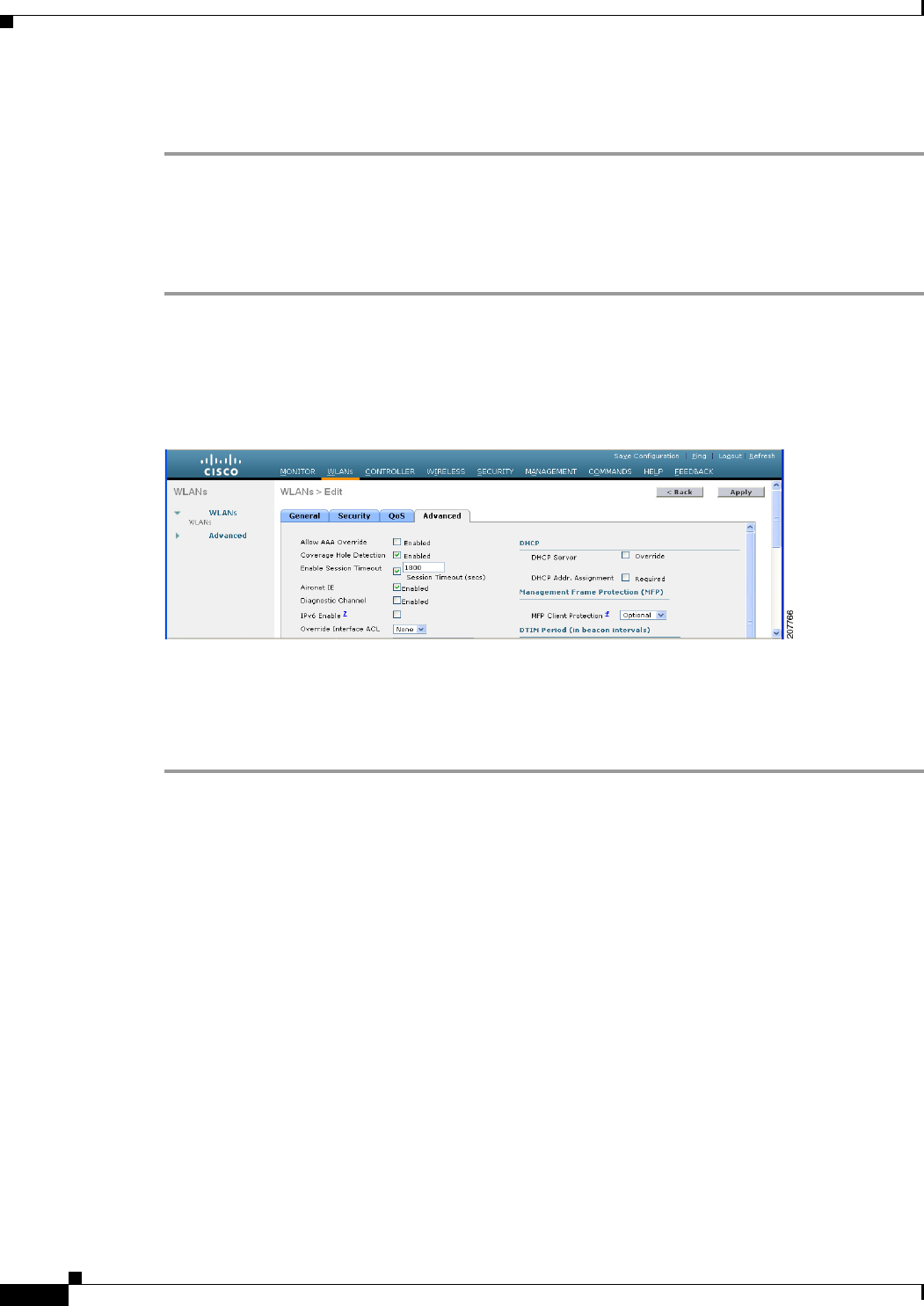
6-88
Cisco Wireless LAN Controller Configuration Guide
OL-21524-02
Chapter 6 Configuring Security Solutions
Configuring Identity Networking
Step 9 Add a RADIUS client (if not already added). Choose Cisco WLAN Controller from the Make/Model
drop-down list.
Using the GUI to Configure AAA Override
To configure AAA override using the controller GUI, follow these steps:
Step 1 Choose WLANs to open the WLANs page.
Step 2 Click the ID number of the WLAN that you want to configure. The WLANs > Edit page appears.
Step 3 Choose the Advanced tab to open the WLANs > Edit (Advanced) page (see Figure 6-42).
Figure 6-42 WLANs > Edit (Advanced) Page
Step 4 Select the Allow AAA Override check box to enable AAA override or unselect it to disable this feature.
The default value is disabled.
Step 5 Click Apply to commit your changes.
Step 6 Click Save Configuration to save your changes.
Using the CLI to Configure AAA Override
Use this command to enable or disable AAA override using the controller CLI:
config wlan aaa-override {enable | disable} wlan_id
For wlan_id, enter an ID from 1 to 16.

6-89
Cisco Wireless LAN Controller Configuration Guide
OL-21524-02
Chapter 6 Configuring Security Solutions
Managing Rogue Devices
Managing Rogue Devices
This section describes security solutions for rogue devices. A rogue device is an unknown access point
or client that is detected by managed access points in your network as not belonging to your system.
Challenges
Rogue access points can disrupt wireless LAN operations by hijacking legitimate clients and using
plain-text or other denial-of-service or man-in-the-middle attacks. That is, a hacker can use a rogue
access point to capture sensitive information, such as usernames and passwords. The hacker can then
transmit a series of clear-to-send (CTS) frames. This action mimics an access point informing a
particular client to transmit and instructing all others to wait, which results in legitimate clients being
unable to access network resources. Wireless LAN service providers have a strong interest in banning
rogue access points from the air space.
Because rogue access points are inexpensive and readily available, employees sometimes plug
unauthorized rogue access points into existing LANs and build ad-hoc wireless networks without IT
department knowledge or consent. These rogue access points can be a serious breach of network security
because they can be plugged into a network port behind the corporate firewall. Because employees
generally do not enable any security settings on the rogue access point, it is easy for unauthorized users
to use the access point to intercept network traffic and hijack client sessions. Even more alarming,
wireless users frequently publish unsecure access point locations, increasing the odds of having
enterprise security breached.
Detecting Rogue Devices
The controller continuously monitors all nearby access points and automatically discovers and collects
information on rogue access points and clients. When the controller discovers a rogue access point, it
uses the Rogue Location Discovery Protocol (RLDP) to determine if the rogue is attached to your
network.
You can configure the controller to use RLDP on all access points or only on access points configured
for monitor (listen-only) mode. The latter option facilitates automated rogue access point detection in a
crowded RF space, allowing monitoring without creating unnecessary interference and without affecting
regular data access point functionality. If you configure the controller to use RLDP on all access points,
the controller always chooses the monitor access point for RLDP operation if a monitor access point and
a local (data) access point are both nearby. If RLDP determines that the rogue is on your network, you
can choose to either manually or automatically contain the detected rogue.
Starting in release 7.0.116.0 and later releases, the controller software provides enhanced rogue
containment strategies. In previous releases, when a rogue device was detected, the controller sent
containment frames at regular intervals to the rogue devices. In release 7.0.116.0 and later, the
containment frames are sent immediately after authorization and associations are detected. The
enhanced containment algorithm provides more effective containment of ad hoc clients.
A rogue access point is moved to a contained state either automatically or manually. The controller
selects the best available access point for containment and pushes the information to the access point.
The access point stores the list of containments per radio. For auto-containment, you can configure the
controller to use only monitor mode access point.
The containment operation happens in following two ways:

6-90
Cisco Wireless LAN Controller Configuration Guide
OL-21524-02
Chapter 6 Configuring Security Solutions
Managing Rogue Devices
• The container access point goes through the list of containments periodically and sends unicast
containment frames. For rogue access point containment, the frames are sent only if there is a rogue
client associated.
• Whenever a contained rogue activity is detected, containment frames are transmitted.
The individual rogue containment involves sending a sequence of unicast disassociation and
deauthentication frames.
Notes about Rogue Devices
Note In a dense RF environment where maximum rogue access points are suspected, the chances of detecting
rogue access points by a local and hybrid-REAP mode access point in channel 157 or 161 are less when
compared to other channels. To mitigate this problem, we recommended that you use dedicate monitor
mode access points.
Note The local and hybrid REAP mode access points are designed to serve associated clients and these access
points spend relatively less time performing off-channel scanning. The access points spend about 50
milliseconds on each channel. If you want to perform high rogue detection, a monitor mode access point
must be used. Alternatively, you can reduce the scan intervals from 180 seconds to a lesser value, for
example, 120 or 60 seconds, ensuring that the radio goes off-channel more frequently which improves
the chances of rogue detection. However, the access point would still spend about 50 milliseconds on
each channel.
Classifying Rogue Access Points
Controller software release 5.0 or later releases improve the classification and reporting of rogue access
points through the use of rogue states and user-defined classification rules that enable rogues to
automatically move between states. In previous releases, the controller listed all rogue access points on
one page sorted by MAC address or BSSID. Now you can create rules that enable the controller to
organize and display rogue access points as Friendly, Malicious, or Unclassified.
By default, none of the classification rules are enabled. Therefore, all unknown access points are
categorized as Unclassified. When you create a rule, configure conditions for it, and enable the rule, the
unclassified access points are reclassified. Whenever you change a rule, it is applied to all access points
(friendly, malicious, and unclassified) in the Alert state only.
Note Rule-based rogue classification does not apply to ad-hoc rogues and rogue clients.
Note The Cisco 5500 Series Controllers support up to 2000 rogues (including acknowledged rogues); the 4400
series controllers, Cisco WiSM, and Catalyst 3750G Integrated Wireless LAN Controller Switch support
up to 625 rogues; and the Cisco 2100 Series Controller and Controller Network Module for Integrated
Services Routers support up to 125 rogues. Each controller limits the number of rogue containments to
three per radio (or six per radio for access points in monitor mode).

6-91
Cisco Wireless LAN Controller Configuration Guide
OL-21524-02
Chapter 6 Configuring Security Solutions
Managing Rogue Devices
When the controller receives a rogue report from one of its managed access points, it responds as
follows:
1. The controller verifies that the unknown access point is in the friendly MAC address list. If it is, the
controller classifies the access point as Friendly.
2. If the unknown access point is not in the friendly MAC address list, the controller starts applying
rogue classification rules.
3. If the rogue is already classified as Malicious, Alert or Friendly, Internal or External, the controller
does not reclassify it automatically. If the rogue is classified differently, the controller reclassifies it
automatically only if the rogue is in the Alert state.
4. The controller applies the first rule based on priority. If the rogue access point matches the criteria
specified by the rule, the controller classifies the rogue according to the classification type
configured for the rule.
5. If the rogue access point does not match any of the configured rules, the controller classifies the
rogue as Unclassified.
6. The controller repeats the previous steps for all rogue access points.
7. If RLDP determines that the rogue access point is on the network, the controller marks the rogue
state as Threat and classifies it as Malicious automatically, even if no rules are configured. You can
then manually contain the rogue (unless you have configured RLDP to automatically contain the
rogue), which would change the rogue state to Contained. If the rogue access point is not on the
network, the controller marks the rogue state as Alert, and you can manually contain the rogue.
8. If desired, you can manually move the access point to a different classification type and rogue state.
Table 6-8 shows the rogue states that can be adopted by a rogue access point in a particular classification
type.
Ta b l e 6-8 Classification Mapping
Rule-Based Classification Type Rogue States
Friendly • Internal—If the unknown access point is inside the network and
poses no threat to WLAN security, you would manually
configure it as Friendly, Internal. An example is the access
points in your lab network.
• External—If the unknown access point is outside the network
and poses no threat to WLAN security, you would manually
configure it as Friendly, External. An example is an access
point that belongs to a neighboring coffee shop.
• Alert—The unknown access point is moved to Alert if it is not
in the neighbor list or in the user-configured friendly MAC list.
Malicious • Alert—The unknown access point is moved to Alert if it is not
in the neighbor list or in the user-configured friendly MAC list.
• Threat—The unknown access point is found to be on the
network and poses a threat to WLAN security.
• Contained—The unknown access point is contained.
• Contained Pending—The unknown access point is marked
Contained, but the action is delayed due to unavailable
resources.

6-92
Cisco Wireless LAN Controller Configuration Guide
OL-21524-02
Chapter 6 Configuring Security Solutions
Managing Rogue Devices
If you upgrade to controller software release 5.0 or later releases, the classification and state of the rogue
access points are reconfigured as follows:
• From Known to Friendly, Internal
• From Acknowledged to Friendly, External
• From Contained to Malicious, Contained
As mentioned previously, the controller can automatically change the classification type and rogue state
of an unknown access point based on user-defined rules, or you can manually move the unknown access
point to a different classification type and rogue state. Table 6-9 shows the allowable classification types
and rogue states from and to which an unknown access point can be configured.
If the rogue state is Contained, you have to uncontain the rogue access point before you can change the
classification type. If you want to move a rogue access point from Malicious to Unclassified, you must
delete the access point and allow the controller to reclassify it.
WCS Interaction
WCS software release 5.0 or later releases also support rule-based classification. WCS uses the
classification rules configured on the controller. The controller sends traps to WCS after the following
events:
Unclassified • Pending—On first detection, the unknown access point is put in
the Pending state for 3 minutes. During this time, the managed
access points determine if the unknown access point is a
neighbor access point.
• Alert—The unknown access point is moved to Alert if it is not
in the neighbor list or in the user-configured friendly MAC list.
• Contained—The unknown access point is contained.
• Contained Pending—The unknown access point is marked
Contained, but the action is delayed due to unavailable
resources.
Table 6-8 Classification Mapping (continued)
Rule-Based Classification Type Rogue States
Ta b l e 6-9 Allowable Classification Type and Rogue State Transitions
From To
Friendly (Internal, External, Alert) Malicious (Alert)
Friendly (Internal, External, Alert) Unclassified (Alert)
Friendly (Alert) Friendly (Internal, External)
Malicious (Alert, Threat) Friendly (Internal, External)
Malicious (Contained, Contained Pending) Malicious (Alert)
Unclassified (Alert, Threat) Friendly (Internal, External)
Unclassified (Contained, Contained Pending) Unclassified (Alert)
Unclassified (Alert) Malicious (Alert)

6-93
Cisco Wireless LAN Controller Configuration Guide
OL-21524-02
Chapter 6 Configuring Security Solutions
Managing Rogue Devices
• If an unknown access point moves to Friendly for the first time, the controller sends a trap to WCS
only if the rogue state is Alert. It does not send a trap if the rogue state is Internal or External.
• If a rogue entry is removed after the timeout expires, the controller sends a trap to WCS for rogue
access points categorized as Malicious (Alert, Threat) or Unclassified (Alert). The controller does
not remove rogue entries with the following rogue states: Contained, Contained Pending, Internal,
and External.
Configuring Rogue Detection
You can configure RLDP to automatically detect and contain rogue devices using the controller GUI or
CLI.
Using the GUI to Configure Rogue Detection
To configure RLDP using the controller GUI, follow these steps:
Step 1 Make sure that rogue detection is enabled on the desired access points. Rogue detection is enabled by
default for all access points joined to the controller (except for OfficeExtend access points). However,
in controller software release 6.0 or later releases, you can enable or disable it for individual access
points by selecting or unselecting the Rogue Detection check box on the All APs > Details for
(Advanced) page.
Note Rogue detection is disabled by default for OfficeExtend access points because these access
points, which are deployed in a home environment, are likely to detect a large number of rogue
devices.
Step 2 Choose Security > Wireless Protection Policies > Rogue Policies > General to open the Rogue
Policies page.
Step 3 Choose one of the following options from the Rogue Location Discovery Protocol drop-down list:
• Disable—Disables RLDP on all access points. This is the default value.
• All APs—Enables RLDP on all access points.
• Monitor Mode APs—Enables RLDP only on access points in monitor mode.
Step 4 In the Expiration Timeout for Rogue AP and Rogue Client Entries text box, enter the number of seconds
after which the rogue access point and client entries expire and are removed from the list. The valid range
is 240 to 3600 seconds, and the default value is 1200 seconds.
Note If a rogue access point or client entry times out, it is removed from the controller only if its rogue
state is Alert or Threat for any classification type.
Step 5 If desired, select the Validate Rogue Clients Against AAA check box to use the AAA server or local
database to validate if rogue clients are valid clients. The default value is unselected.
Step 6 If desired, select the Detect and Report Ad-Hoc Networks check box to enable ad-hoc rogue detection
and reporting. The default value is selected.
Step 7 If you want the controller to automatically contain certain rogue devices, select the following check
boxes. Otherwise, leave the check boxes unselected, which is the default value.

6-94
Cisco Wireless LAN Controller Configuration Guide
OL-21524-02
Chapter 6 Configuring Security Solutions
Managing Rogue Devices
Caution When you enable any of these parameters, the following warning appears: “Using this feature may have
legal consequences. Do you want to continue?” The 2.4- and 5-GHz frequencies in the Industrial,
Scientific, and Medical (ISM) band are open to the public and can be used without a license. As such,
containing devices on another party’s network could have legal consequences.
• Auto Containment Level—Set the auto containment level by selecting a value from the drop-down
list. The default is 1.
• Auto Containment only for monitor mode APs—Enable the check box if you want to use only
monitor mode access points for auto-containment.
• Rogue on Wire—Automatically contains rogues that are detected on the wired network.
• Using Our SSID—Automatically contains rogues that are advertising your network’s SSID. If you
leave this parameter unselected, the controller only generates an alarm when such a rogue is
detected.
• Valid Client on Rogue AP—Automatically contains a rogue access point to which trusted clients
are associated. If you leave this parameter unselected, the controller only generates an alarm when
such a rogue is detected.
• AdHoc Rogue AP—Automatically contains ad-hoc networks detected by the controller. If you leave
this parameter unselected, the controller only generates an alarm when such a network is detected.
Step 8 Click Apply to commit your changes.
Step 9 Click Save Configuration to save your changes.
Using the CLI to Configure RLDP
To configure RLDP using the controller CLI, follow these steps:
Step 1 Make sure that rogue detection is enabled on the desired access points. Rogue detection is enabled by
default for all access points joined to the controller (except for OfficeExtend access points). However,
in controller software release 6.0 or later releases, you can enable or disable it for individual access
points by entering the config rogue detection {enable | disable} Cisco_AP command.
Note To see the current rogue detection configuration for a specific access point, enter the show ap
config general Cisco_AP command.
Note Rogue detection is disabled by default for OfficeExtend access points because these access
points, which are deployed in a home environment, are likely to detect a large number of rogue
devices.
Step 2 Enable, disable, or initiate RLDP by entering these commands:
• config rogue ap rldp enable alarm-only—Enables RLDP on all access points.
• config rogue ap rldp enable alarm-only monitor_ap_only—Enables RLDP only on access points
in monitor mode.

6-95
Cisco Wireless LAN Controller Configuration Guide
OL-21524-02
Chapter 6 Configuring Security Solutions
Managing Rogue Devices
• config rogue ap rldp initiate rogue_mac_address—Initiates RLDP on a specific rogue access
point.
• config rogue ap rldp disable—Disables RLDP on all access points.
Step 3 Specify the number of seconds after which the rogue access point and client entries expire and are
removed from the list by entering this command:
config rogue ap timeout seconds
The valid range for the seconds parameter is 240 to 3600 seconds (inclusive), and the default value is
1200 seconds.
Note If a rogue access point or client entry times out, it is removed from the controller only if its rogue
state is Alert or Threat for any classification type.
Step 4 Enable or disable ad-hoc rogue detection and reporting by entering this command:
config rogue adhoc {enable | disable}
Step 5 Enable or disable the AAA server or local database to validate if rogue clients are valid clients by
entering this command:
config rogue client aaa {enable | disable}
Step 6 If you want the controller to automatically contain certain rogue devices, enter these commands.
Caution When you enter any of these commands, the following warning appears: “Using this feature may have
legal consequences. Do you want to continue?” The 2.4- and 5-GHz frequencies in the Industrial,
Scientific, and Medical (ISM) band are open to the public and can be used without a license. As such,
containing devices on another party’s network could have legal consequences.
• config rogue ap rldp enable auto-contain—Automatically contains rogues that are detected on the
wired network.
• config rogue ap ssid auto-contain—Automatically contains rogues that are advertising your
network’s SSID.
Note If you want the controller to only generate an alarm when such a rogue is detected, enter the
config rogue ap ssid alarm command.
• config rogue ap valid-client auto-contain—Automatically contains a rogue access point to which
trusted clients are associated.
Note If you want the controller to only generate an alarm when such a rogue is detected, enter the
config rogue ap valid-client alarm command.
• config rogue adhoc auto-contain—Automatically contains adhoc networks detected by the
controller.
Note If you want the controller to only generate an alarm when such a network is detected, enter
the config rogue adhoc alert command.
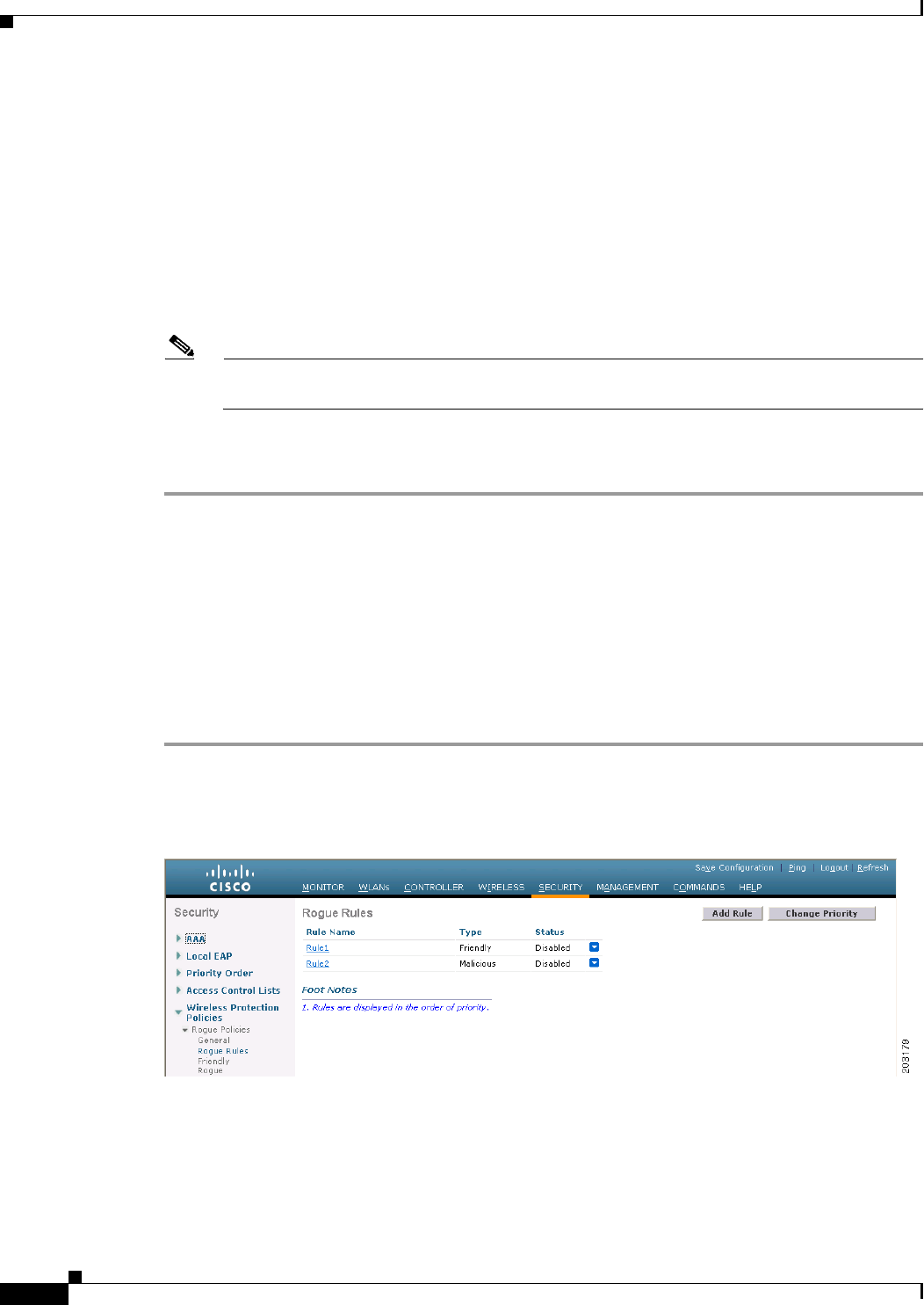
6-96
Cisco Wireless LAN Controller Configuration Guide
OL-21524-02
Chapter 6 Configuring Security Solutions
Managing Rogue Devices
• configure rogue auto-containment level {1 - 4}—Set the auto containment level by entering a
value between 1 and 4. The default is 1.
• config rogue auto-contain level 1 monitor_mode_ap_only—Automatically contains only monitor
mode access points.
Step 7 Configure RLDP scheduling by entering the following command:
• config rogue ap rldp schedule add—Enables you to schedule RLDP on a particular day of the
week. You must enter the day of the week (for example mon, tue, wed, and so on) on which you
want to schedule RLDP and the start time and end time in HH:MM:SS format. Here is an example:
config rogue ap rldp schedule add mon 22:00:00 23:00:00
Note When you configure RLDP scheduling, it is assumed that the scheduling would occur in the
future, that is, after the configuration is saved.
Step 8 Save your changes by entering this command:
save config
Configuring Rogue Classification Rules
You can configure up to 64 rogue classification rules per controller using the controller GUI or CLI.
Using the GUI to Configure Rogue Classification Rules
To configure rogue classification rules using the controller GUI, follow these steps:
Step 1 Choose Security > Wireless Protection Policies > Rogue Policies > Rogue Rules to open the Rogue
Rules page (see Figure 6-43).
Figure 6-43 Rogue Rules Page
Any rules that have already been created are listed in priority order. The name, type, and status of each
rule is provided.
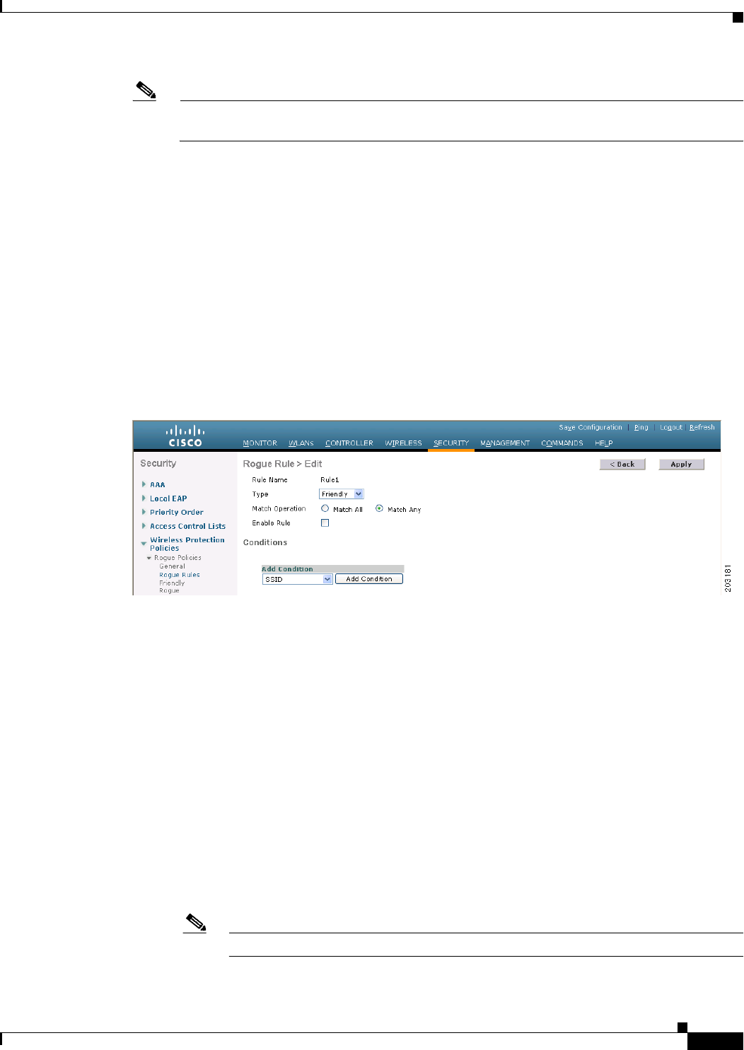
6-97
Cisco Wireless LAN Controller Configuration Guide
OL-21524-02
Chapter 6 Configuring Security Solutions
Managing Rogue Devices
Note If you ever want to delete a rule, hover your cursor over the blue drop-down arrow for that rule
and click Remove.
Step 2 Create a new rule as follows:
a. Click Add Rule. An Add Rule section appears at the top of the page.
b. In the Rule Name text box, enter a name for the new rule. Make sure that the name does not contain
any spaces.
c. From the Rule Type drop-down list, choose Friendly or Malicious to classify rogue access points
matching this rule as friendly or malicious.
d. Click Add to add this rule to the list of existing rules, or click Cancel to discard this new rule.
Step 3 Edit a rule as follows:
a. Click the name of the rule that you want to edit. The Rogue Rule > Edit page appears (see
Figure 6-44).
Figure 6-44 Rogue Rule > Edit Page
b. From the Type drop-down list, choose Friendly or Malicious to classify rogue access points
matching this rule as friendly or malicious.
c. From the Match Operation text box, choose one of the following:
• Match All—If this rule is enabled, a detected rogue access point must meet all of the conditions
specified by the rule in order for the rule to be matched and the rogue to adopt the classification
type of the rule.
• Match Any—If this rule is enabled, a detected rogue access point must meet any of the
conditions specified by the rule in order for the rule to be matched and the rogue to adopt the
classification type of the rule. This is the default value.
d. To enable this rule, select the Enable Rule check box. The default value is unselected.
e. From the Add Condition drop-down list, choose one or more of the following conditions that the
rogue access point must meet and click Add Condition.
• SSID—Requires that the rogue access point have a specific user-configured SSID. If you choose
this option, enter the SSID in the User Configured SSID text box, and click Add SSID.
Note To delete an SSID, highlight the SSID and click Remove.
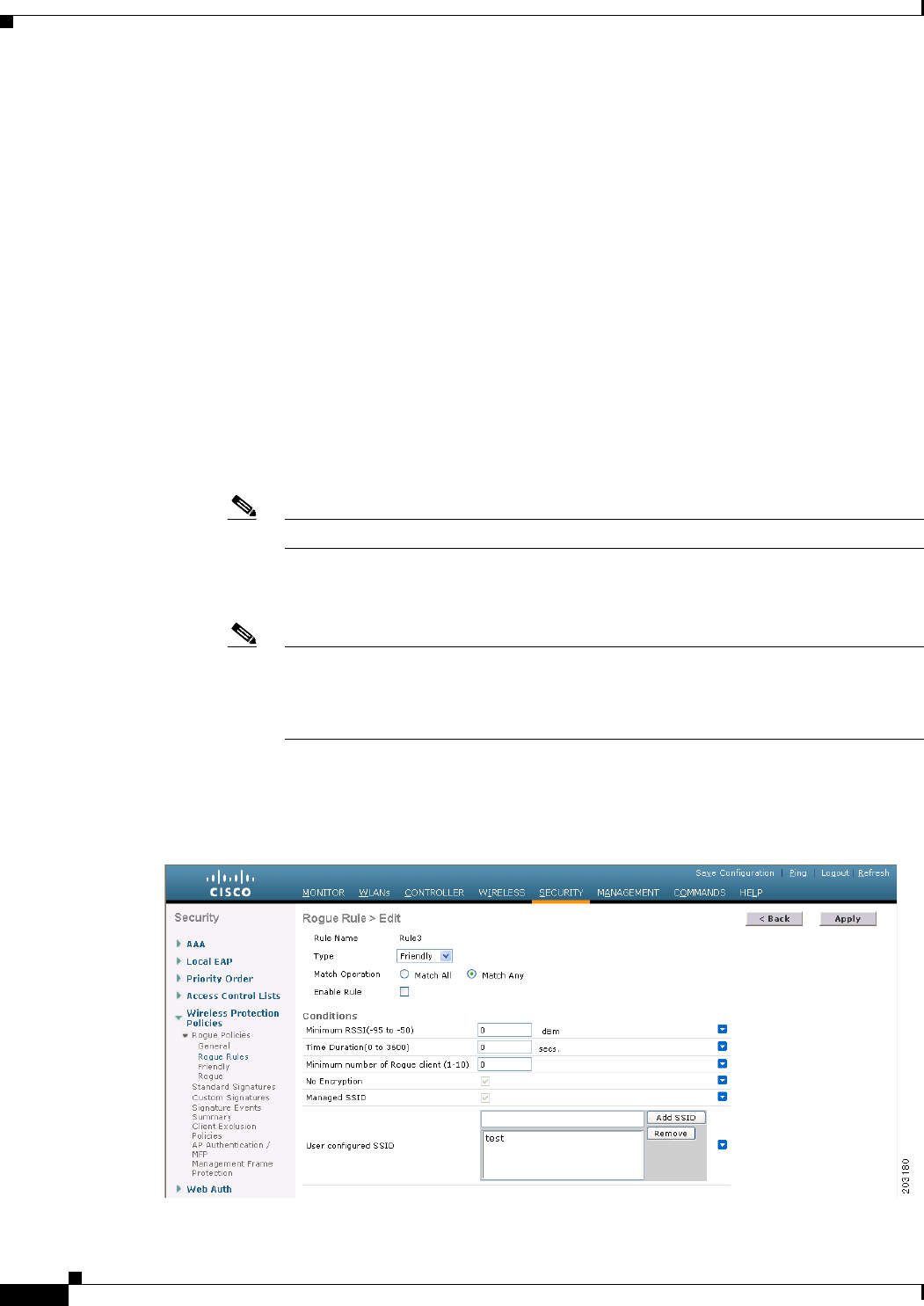
6-98
Cisco Wireless LAN Controller Configuration Guide
OL-21524-02
Chapter 6 Configuring Security Solutions
Managing Rogue Devices
• RSSI—Requires that the rogue access point have a minimum received signal strength indication
(RSSI) value. For example, if the rogue access point has an RSSI that is greater than the
configured value, then the access point could be classified as malicious. If you choose this
option, enter the minimum RSSI value in the Minimum RSSI text box. The valid range is –95
to –50 dBm (inclusive), and the default value is 0 dBm.
• Duration—Requires that the rogue access point be detected for a minimum period of time. If
you choose this option, enter a value for the minimum detection period in the Time Duration
text box. The valid range is 0 to 3600 seconds (inclusive), and the default value is 0 seconds.
• Client Count—Requires that a minimum number of clients be associated to the rogue access
point. For example, if the number of clients associated to the rogue access point is greater than
or equal to the configured value, then the access point could be classified as malicious. If you
choose this option, enter the minimum number of clients to be associated to the rogue access
point in the Minimum Number of Rogue Clients text box. The valid range is 1 to 10 (inclusive),
and the default value is 0.
• No Encryption—Requires that the rogue access point’s advertised WLAN does not have
encryption enabled. If a rogue access point has encryption disabled, it is likely that more clients
will try to associate to it. No further configuration is required for this option.
Note WCS refers to this option as “Open Authentication.”
• Managed SSID—Requires that the rogue access point’s managed SSID (the SSID configured
for the WLAN) be known to the controller. No further configuration is required for this option.
Note The SSID and Managed SSID conditions cannot be used with the Match All operation
because these two SSID lists are mutually exclusive. If you define a rule with Match All
and have these two conditions configured, the rogue access points are never classified
as friendly or malicious because one of the conditions can never be met.
You can add up to six conditions per rule. When you add a condition, it appears under the Conditions
section (see Figure 6-45).
Figure 6-45 Rogue Rule > Edit Page
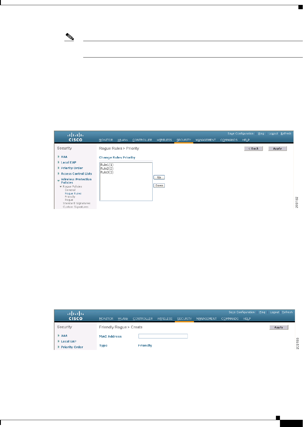
6-99
Cisco Wireless LAN Controller Configuration Guide
OL-21524-02
Chapter 6 Configuring Security Solutions
Managing Rogue Devices
Note If you ever want to delete a condition from this rule, hover your cursor over the blue
drop-down arrow for that condition and click Remove.
f. Click Apply to commit your changes.
Step 4 Click Save Configuration to save your changes.
Step 5 If you want to change the order in which rogue classification rules are applied, follow these steps:
a. Click Back to return to the Rogue Rules page.
b. Click Change Priority to access the Rogue Rules > Priority page (see Figure 6-46).
Figure 6-46 Rogue Rules > Priority Page
The rogue rules are listed in priority order in the Change Rules Priority text box.
c. Highlight the rule for which you want to change the priority, and click Up to raise its priority in the
list or Down to lower its priority in the list.
d. Continue to move the rules up or down until the rules are in the desired order.
e. Click Apply to commit your changes.
Step 6 Classify any rogue access points as friendly and add them to the friendly MAC address list as follows:
a. Choose Security > Wireless Protection Policies > Rogue Policies > Friendly Rogue to open the
Friendly Rogue > Create page (see Figure 6-47).
Figure 6-47 Friendly Rogue > Create Page
b. In the MAC Address text box, enter the MAC address of the friendly rogue access point.
c. Click Apply to commit your changes.

6-100
Cisco Wireless LAN Controller Configuration Guide
OL-21524-02
Chapter 6 Configuring Security Solutions
Managing Rogue Devices
d. Click Save Configuration to save your changes. This access point is added to the controller’s list
of friendly access points and should now appear on the Friendly Rogue APs page.
Using the CLI to Configure Rogue Classification Rules
To configure rogue classification rules using the controller CLI, follow these steps:
Step 1 Create a rule by entering this command:
config rogue rule add ap priority priority classify {friendly | malicious} rule_name
Note If you later want to change the priority of this rule and shift others in the list accordingly, enter
the config rogue rule priority priority rule_name command. If you later want to change the
classification of this rule, enter the config rogue rule classify {friendly | malicious} rule_name
command.
Note If you ever want to delete all of the rogue classification rules or a specific rule, enter the config
rogue rule delete {all | rule_name} command.
Step 2 Disable all rules or a specific rule by entering this command:
config rogue rule disable {all | rule_name}
Note A rule must be disabled before you can modify its attributes.
Step 3 Add conditions to a rule that the rogue access point must meet by entering this command:
config rogue rule condition ap set condition_type condition_value rule_name
where condition_type is one of the following:
• ssid—Requires that the rogue access point have a specific SSID. You should add SSIDs that are not
managed by the controller. If you choose this option, enter the SSID for the condition_value
parameter. The SSID is added to the user-configured SSID list.
Note If you ever want to delete all of the SSIDs or a specific SSID from the user-configured SSID
list, enter the config rogue rule condition ap delete ssid {all | ssid} rule_name command.
• rssi—Requires that the rogue access point have a minimum RSSI value. For example, if the rogue
access point has an RSSI that is greater than the configured value, then the access point could be
classified as malicious. If you choose this option, enter the minimum RSSI value for the
condition_value parameter. The valid range is –95 to –50 dBm (inclusive), and the default value is
0 dBm.
• duration—Requires that the rogue access point be detected for a minimum period of time. If you
choose this option, enter a value for the minimum detection period for the condition_value
parameter. The valid range is 0 to 3600 seconds (inclusive), and the default value is 0 seconds.

6-101
Cisco Wireless LAN Controller Configuration Guide
OL-21524-02
Chapter 6 Configuring Security Solutions
Managing Rogue Devices
• client-count—Requires that a minimum number of clients be associated to the rogue access point.
For example, if the number of clients associated to the rogue access point is greater than or equal to
the configured value, then the access point could be classified as malicious. If you choose this
option, enter the minimum number of clients to be associated to the rogue access point for the
condition_value parameter. The valid range is 1 to 10 (inclusive), and the default value is 0.
• no-encryption—Requires that the rogue access point’s advertised WLAN does not have encryption
enabled. A condition_value parameter is not required for this option.
• managed-ssid—Requires that the rogue access point’s SSID be known to the controller. A
condition_value parameter is not required for this option.
Note You can add up to six conditions per rule. If you ever want to delete all of the conditions or a
specific condition from a rule, enter the config rogue rule condition ap delete {all |
condition_type} condition_value rule_name command.
Step 4 Specify whether a detected rogue access point must meet all or any of the conditions specified by the
rule in order for the rule to be matched and the rogue access point to adopt the classification type of the
rule by entering this command:
config rogue rule match {all | any} rule_name
Step 5 Enable all rules or a specific rule by entering this command:
config rogue rule enable {all | rule_name}
Note For your changes to become effective, you must enable the rule.
Step 6 Add a new friendly access point entry to the friendly MAC address list or delete an existing friendly
access point entry from the list by entering this command:
config rogue ap friendly {add | delete} ap_mac_address
Step 7 Save your changes by entering this command:
save config
Step 8 View the rogue classification rules that are configured on the controller by entering this command:
show rogue rule summary
Information similar to the following appears:
Priority Rule Name State Type Match Hit Count
-------- ----------- -------- ------------ ------ ---------
1 Rule1 Disabled Friendly Any 0
2 Rule2 Enabled Malicious Any 339
3 Rule3 Disabled Friendly Any 0
Step 9 View detailed information for a specific rogue classification rule by entering this command:
show rogue rule detailed rule_name
Information similar to the following appears:
Priority......................................... 2
Rule Name........................................ Rule2
State............................................ Enabled
Type............................................. Malicious
Match Operation.................................. Any
Hit Count........................................ 352
Total Conditions................................. 6

6-102
Cisco Wireless LAN Controller Configuration Guide
OL-21524-02
Chapter 6 Configuring Security Solutions
Managing Rogue Devices
Condition 1
type......................................... Client-count
value........................................ 10
Condition 2
type......................................... Duration
value (seconds).............................. 2000
Condition 3
type......................................... Managed-ssid
value........................................ Enabled
Condition 4
type......................................... No-encryption
value........................................ Enabled
Condition 5
type......................................... Rssi
value (dBm).................................. -50
Condition 6
type......................................... Ssid
SSID Count................................... 1
SSID 1.................................... test
Viewing and Classifying Rogue Devices
Using the controller GUI or CLI, you can view rogue devices and determine the action that the controller
should take.
Caution When you choose to contain a rogue device, the following warning appears: “There may be legal issues
following this containment. Are you sure you want to continue?” The 2.4- and 5-GHz frequencies in the
Industrial, Scientific, and Medical (ISM) band are open to the public and can be used without a license.
As such, containing devices on another party’s network could have legal consequences.
Using the GUI to View and Classify Rogue Devices
To view and classify rogue devices using the controller GUI, follow these steps:
Step 1 Choose Monitor > Rogues.
Step 2 Choose the following options to view the different types of rogue access points detected by the
controller:
• Friendly APs
• Malicious APs
• Unclassified APs
A page similar to the following appears (see Figure 6-48).
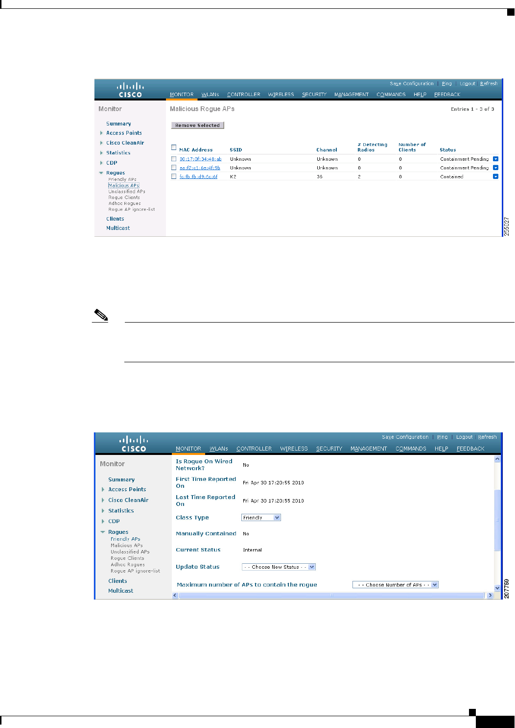
6-103
Cisco Wireless LAN Controller Configuration Guide
OL-21524-02
Chapter 6 Configuring Security Solutions
Managing Rogue Devices
Figure 6-48 Friendly Rogue APs Page
The Friendly Rogue APs page, Malicious Rogue APs page, and Unclassified Rogue APs page provide
the following information: the MAC address and SSID of the rogue access point, Channel Number, the
number of clients connected to the rogue access point, the number of radios that detected the rogue
access point, and the current status of the rogue access point.
Note If you ever want to delete a rogue access point from one of these pages, hover your cursor over
the blue drop-down arrow and click Remove. To delete multiple rogue access points, check the
check box corresponding to the row you want to delete and click Remove Selected.
Step 3 Obtain more details about a rogue access point by clicking the MAC address of the access point. The
Rogue AP Detail page appears (see Figure 6-49).
Figure 6-49 Rogue AP Detail Page
This page provides the following information: the MAC address of the rogue device, the type of rogue
device (such as an access point), whether the rogue device is on the wired network, the dates and times
when the rogue device was first and last reported, and the current status of the device.
The Class Type text box shows the current classification for this rogue access point:

6-104
Cisco Wireless LAN Controller Configuration Guide
OL-21524-02
Chapter 6 Configuring Security Solutions
Managing Rogue Devices
• Friendly—An unknown access point that matches the user-defined friendly rules or an existing
known and acknowledged rogue access point. Friendly access points cannot be contained.
• Malicious—An unknown access point that matches the user-defined malicious rules or is moved
manually by the user from the Friendly or Unclassified classification type.
Note Once an access point is classified as Malicious, you cannot apply rules to it in the future,
and it cannot be moved to another classification type. If you want to move a malicious access
point to the Unclassified classification type, you must delete the access point and allow the
controller to reclassify it.
• Unclassified—An unknown access point that does not match the user-defined friendly or malicious
rules. An unclassified access point can be contained. It can also be moved to the Friendly or
Malicious classification type automatically in accordance with user-defined rules or manually by the
user.
Step 4 If you want to change the classification of this device, choose a different classification from the Class
Type drop-down list.
Note A rogue access point cannot be moved to another class if its current state is Contain.
Step 5 From the Update Status drop-down list, choose one of the following options to specify how the controller
should respond to this rogue access point:
• Internal—The controller trusts this rogue access point. This option is available if the Class Type is
set to Friendly.
• External—The controller acknowledges the presence of this rogue access point. This option is
available if the Class Type is set to Friendly.
• Contain—The controller contains the offending device so that its signals no longer interfere with
authorized clients. This option is available if the Class Type is set to Malicious or Unclassified.
• Alert—The controller forwards an immediate alert to the system administrator for further action.
This option is available if the Class Type is set to Malicious or Unclassified.
The bottom of the page provides information on both the access points that detected this rogue access
point and any clients that are associated to it. To see more details for any of the clients, click Edit to
open the Rogue Client Detail page.
Step 6 Click Apply to commit your changes.
Step 7 Click Save Configuration to save your changes.
Step 8 View any rogue clients that are connected to the controller by choosing Rogue Clients. The Rogue
Clients page appears. This page shows the following information: the MAC address of the rogue client,
the MAC address of the access point to which the rogue client is associated, the SSID of the rogue client,
the number of radios that detected the rogue client, the date and time when the rogue client was last
reported, and the current status of the rogue client.
Step 9 Obtain more details about a rogue client by clicking the MAC address of the client. The Rogue Client
Detail page appears (see Figure 6-50).
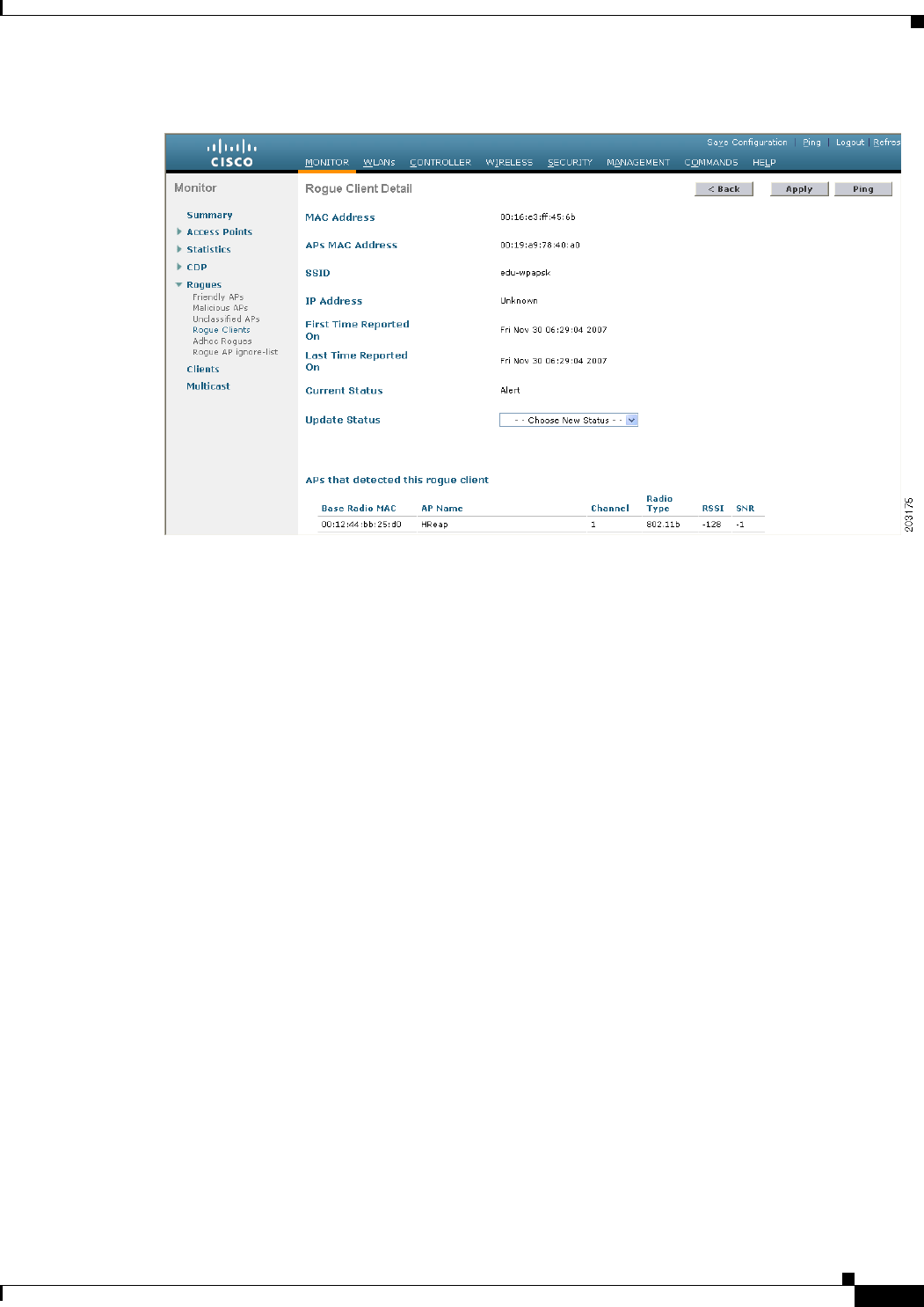
6-105
Cisco Wireless LAN Controller Configuration Guide
OL-21524-02
Chapter 6 Configuring Security Solutions
Managing Rogue Devices
Figure 6-50 Rogue Client Detail Page
This page provides the following information: the MAC address of the rogue client, the MAC address of
the rogue access point to which this client is associated, the SSID and IP address of the rogue client, the
dates and times when the rogue client was first and last reported, and the current status of the rogue
client.
Step 10 From the Update Status drop-down list, choose one of the following options to specify how the controller
should respond to this rogue client:
• Contain—The controller contains the offending device so that its signals no longer interfere with
authorized clients.
• Alert—The controller forwards an immediate alert to the system administrator for further action.
The bottom of the page provides information on the access points that detected this rogue client.
Step 11 Click Apply to commit your changes.
Step 12 If desired, you can test the controller’s connection to this client by clicking Ping.
Step 13 Click Save Configuration to save your changes.
Step 14 See any ad-hoc rogues detected by the controller by choosing Adhoc Rogues. The Adhoc Rogues page
appears (see Figure 6-51).
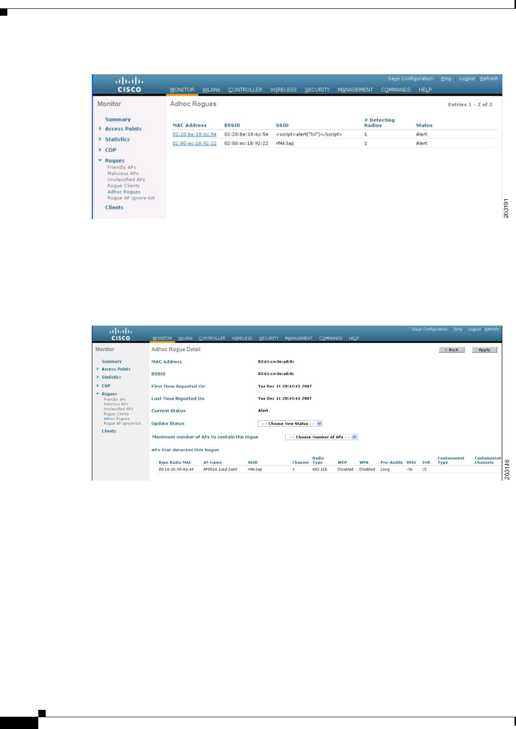
6-106
Cisco Wireless LAN Controller Configuration Guide
OL-21524-02
Chapter 6 Configuring Security Solutions
Managing Rogue Devices
Figure 6-51 Adhoc Rogues Page
This page shows the following information: the MAC address, BSSID, and SSID of the ad-hoc rogue,
the number of radios that detected the ad-hoc rogue, and the current status of the ad-hoc rogue.
Step 15 Obtain more details about an ad-hoc rogue by clicking the MAC address of the rogue. The Adhoc Rogue
Detail page appears (see Figure 6-52).
Figure 6-52 Adhoc Rogue Detail Page
This page provides the following information: the MAC address and BSSID of the ad-hoc rogue, the
dates and times when the rogue was first and last reported, and the current status of the rogue.
Step 16 From the Update Status drop-down list, choose one of the following options to specify how the controller
should respond to this ad-hoc rogue:
• Contain—The controller contains the offending device so that its signals no longer interfere with
authorized clients.
• Alert—The controller forwards an immediate alert to the system administrator for further action.
• Internal—The controller trusts this rogue access point.
• External—The controller acknowledges the presence of this rogue access point.
Step 17 From the Maximum Number of APs to Contain the Rogue drop-down list, choose one of the following
options to specify the maximum number of access points used to contain this ad-hoc rogue: 1, 2, 3, or 4.
The bottom of the page provides information on the access points that detected this ad-hoc rogue.
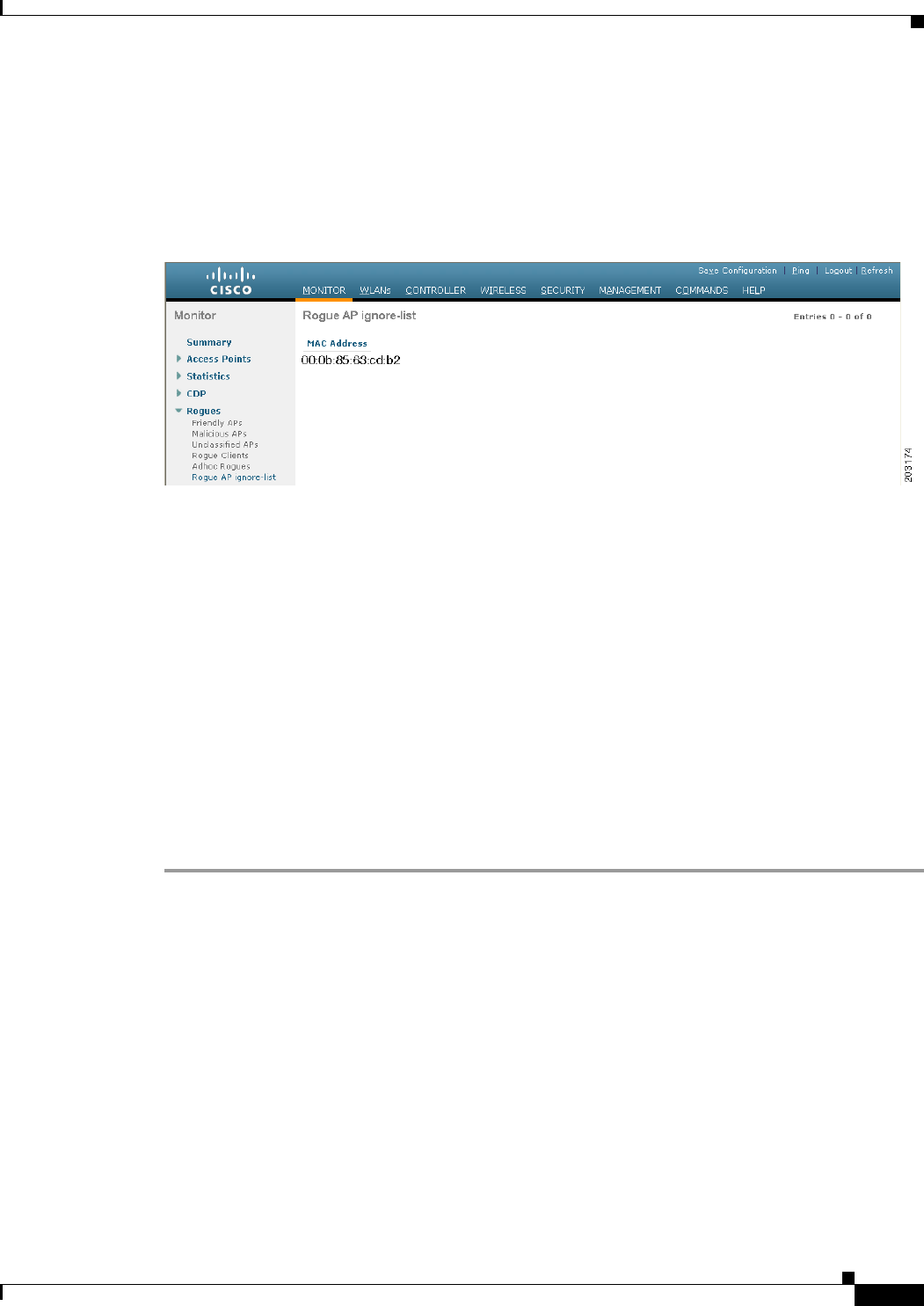
6-107
Cisco Wireless LAN Controller Configuration Guide
OL-21524-02
Chapter 6 Configuring Security Solutions
Managing Rogue Devices
Step 18 Click Apply to commit your changes.
Step 19 Click Save Configuration to save your changes.
Step 20 View any access points that have been configured to be ignored by choosing Rogue AP Ignore-List. The
Rogue AP Ignore-List page appears (see Figure 6-53).
Figure 6-53 Rogue AP Ignore-List Page
This page shows the MAC addresses of any access points that are configured to be ignored. The
rogue-ignore list contains a list of any autonomous access points that have been manually added to WCS
maps by WCS users. The controller regards these autonomous access points as rogues even though WCS
is managing them. The rogue-ignore list allows the controller to ignore these access points. The list is
updated as follows:
• When the controller receives a rogue report, it checks to see if the unknown access point is in the
rogue-ignore access point list.
• If the unknown access point is in the rogue-ignore list, the controller ignores this access point and
continues to process other rogue access points.
• If the unknown access point is not in the rogue-ignore list, the controller sends a trap to WCS. If
WCS finds this access point in its autonomous access point list, WCS sends a command to the
controller to add this access point to the rogue-ignore list. This access point is then ignored in future
rogue reports.
• If a user removes an autonomous access point from WCS, WCS sends a command to the controller
to remove this access point from the rogue-ignore list.
Using the CLI to View and Classify Rogue Devices
To view and classify rogue devices using the controller CLI, use these commands:
• View a list of all rogue access points detected by the controller by entering this command:
show rogue ap summary
Information similar to the following appears:
Rogue Location Discovery Protocol................ Enabled
Rogue AP timeout................................. 1200
MAC Address Classification # APs # Clients Last Heard
----------------- ------------------ ----- --------- -----------------------
00:0a:b8:7f:08:c0 Friendly 0 0 Not Heard
00:0b:85:01:30:3f Malicious 1 0 Fri Nov 30 11:30:59 2007

6-108
Cisco Wireless LAN Controller Configuration Guide
OL-21524-02
Chapter 6 Configuring Security Solutions
Managing Rogue Devices
00:0b:85:63:70:6f Malicious 1 0 Fri Nov 30 11:20:14 2007
00:0b:85:63:cd:bf Malicious 1 0 Fri Nov 30 11:23:12 2007
...
• See a list of the friendly rogue access points detected by the controller by entering this command:
show rogue ap friendly summary
Information similar to the following appears:
Number of APs.................................... 1
MAC Address State # APs # Clients Last Heard
----------------- ------------------ ----- --------- ---------------------------
00:0a:b8:7f:08:c0 Internal 1 0 Tue Nov 27 13:52:04 2007
• See a list of the malicious rogue access points detected by the controller by entering this command:
show rogue ap malicious summary
Information similar to the following appears:
Number of APs.................................... 264
MAC Address State # APs # Clients Last Heard
----------------- ------------------ ----- --------- -----------------------
00:0b:85:01:30:3f Alert 1 0 Fri Nov 30 11:20:01 2007
00:0b:85:63:70:6f Alert 1 0 Fri Nov 30 11:20:14 2007
00:0b:85:63:cd:bf Alert 1 0 Fri Nov 30 11:23:12 2007
00:0b:85:63:cd:dd Alert 1 0 Fri Nov 30 11:27:03 2007
00:0b:85:63:cd:de Alert 1 0 Fri Nov 30 11:26:23 2007
00:0b:85:63:cd:df Alert 1 0 Fri Nov 30 11:26:50 2007
...
• See a list of the unclassified rogue access points detected by the controller by entering this
command:
show rogue ap unclassified summary
Information similar to the following appears:
Number of APs.................................... 164
MAC Address State # APs # Clients Last Heard
----------------- ------------------ ----- --------- -----------------------
00:0b:85:63:cd:bd Alert 1 0 Fri Nov 30 11:12:52 2007
00:0b:85:63:cd:e7 Alert 1 0 Fri Nov 30 11:29:01 2007
00:0b:85:63:ce:05 Alert 1 0 Fri Nov 30 11:26:23 2007
00:0b:85:63:ce:07Alert 1 0 Fri Nov 30 11:26:23 2007
...
• See detailed information for a specific rogue access point by entering this command:
show rogue ap detailed ap_mac_address
Information similar to the following appears:
Rogue BSSID...................................... 00:1d:70:59:95:9d
Rogue Radio Type................................. 802.11a
State............................................ Alert
First Time Rogue was Reported.................... Tue Sep 21 09:57:08 2010
Last Time Rogue was Reported..................... Tue Sep 21 10:00:56 2010
Rogue Client IP address.......................... Not known
Reported By
AP 1
MAC Address.............................. 68:ef:bd:e1:fd:30
Name..................................... AP5475.d074.48e4

6-109
Cisco Wireless LAN Controller Configuration Guide
OL-21524-02
Chapter 6 Configuring Security Solutions
Managing Rogue Devices
RSSI..................................... -80 dBm
SNR...................................... 18 dB
Channel.................................. 40
Last reported by this AP................. Tue Sep 21 10:00:56 2010
• See the rogue report (which shows the number of rogue devices detected on different channel
widths) for a specific 802.11a/n radio by entering this command:
show ap auto-rf 802.11a Cisco_AP
Information similar to the following appears:
Number Of Slots.................................. 2
AP Name.......................................... AP2
MAC Address...................................... 00:1b:d5:13:39:74
Radio Type..................................... RADIO_TYPE_80211a
Noise Information
Noise Profile................................ PASSED
Channel 36................................... -80 dBm
Channel 40................................... -78 dBm
...
Interference Information
Interference Profile......................... PASSED
Channel 36................................... -81 dBm @ 8 % busy
Channel 40................................... -66 dBm @ 4 % busy
...
Rogue Histogram (20/40_ABOVE/40_BELOW)
Channel 36................................... 21/ 1/ 0
Channel 40................................... 7/ 0/ 0
...
• See a list of all rogue clients that are associated to a rogue access point by entering this command:
show rogue ap clients ap_mac_address
Information similar to the following appears:
MAC Address State # APs Last Heard
----------------- ------------------ ----- -------------------------
00:bb:cd:12:ab:ff Alert 1 Fri Nov 30 11:26:23 2007
• See a list of all rogue clients detected by the controller by entering this command:
show rogue client summary
Information similar to the following appears:
Validate rogue clients against AAA............... Disabled
MAC Address State # APs Last Heard
----------------- ------------------ ----- -----------------------
00:0a:8a:7d:f5:f5 Alert 1 Mon Dec 3 21:56:36 2007
00:18:ba:78:c4:44 Alert 1 Mon Dec 3 21:59:36 2007
00:18:ba:78:c4:d1 Alert 1 Mon Dec 3 21:47:36 2007
00:18:ba:78:ca:f8 Alert 1 Mon Dec 3 22:02:36 2007
...
• See detailed information for a specific rogue client by entering this command:
show rogue client detailed client_mac_address
Information similar to the following appears:
Rogue BSSID...................................... 00:0b:85:23:ea:d1
State............................................ Alert
First Time Rogue was Reported.................... Mon Dec 3 21:50:36 2007
Last Time Rogue was Reported..................... Mon Dec 3 21:50:36 2007

6-110
Cisco Wireless LAN Controller Configuration Guide
OL-21524-02
Chapter 6 Configuring Security Solutions
Managing Rogue Devices
Rogue Client IP address.......................... Not known
Reported By
AP 1
MAC Address.............................. 00:15:c7:82:b6:b0
Name..................................... AP0016.47b2.31ea
Radio Type............................... 802.11a
RSSI..................................... -71 dBm
SNR...................................... 23 dB
Channel.................................. 149
Last reported by this AP.............. Mon Dec 3 21:50:36 2007
• See a list of all ad-hoc rogues detected by the controller by entering this command:
show rogue adhoc summary
Information similar to the following appears:
Detect and report Ad-Hoc Networks................ Enabled
Client MAC Address Adhoc BSSID State # APs Last Heard
------------------ ------------------ ----------- ------- ------------------------
00:bb:cd:12:ab:ff super Alert 1 Fri Nov 30 11:26:23 2007
• See detailed information for a specific ad-hoc rogue by entering this command:
show rogue adhoc detailed rogue_mac_address
Information similar to the following appears:
Adhoc Rogue MAC address.......................... 02:61:ce:8e:a8:8c
Adhoc Rogue BSSID................................ 02:61:ce:8e:a8:8c
State............................................ Alert
First Time Adhoc Rogue was Reported.............. Tue Dec 11 20:45:45 2007
Last Time Adhoc Rogue was Reported............... Tue Dec 11 20:45:45 2007
Reported By
AP 1
MAC Address.............................. 00:14:1b:58:4a:e0
Name..................................... AP0014.1ced.2a60
Radio Type............................... 802.11b
SSID..................................... rf4k3ap
Channel.................................. 3
RSSI..................................... -56 dBm
SNR...................................... 15 dB
Encryption............................... Disabled
ShortPreamble............................ Disabled
WPA Support.............................. Disabled
Last reported by this AP............... Tue Dec 11 20:45:45 2007
• See a list of rogue access points that are configured to be ignore by entering this command:
show rogue ignore-list
Information similar to the following appears:
MAC Address
------------------
10:bb:17:cc:01:ef
Note See Step 20 of the “Using the GUI to View and Classify Rogue Devices” section on
page 6-102 for more information on the rogue-ignore access point list.
• Classify a rogue access point as friendly by entering this command:
config rogue ap classify friendly state {internal | external} ap_mac_address

6-111
Cisco Wireless LAN Controller Configuration Guide
OL-21524-02
Chapter 6 Configuring Security Solutions
Managing Rogue Devices
where
• internal means that the controller trusts this rogue access point.
• external means that the controller acknowledges the presence of this rogue access point.
Note A rogue access point cannot be moved to the Friendly class if its current state is Contain.
• Mark a rogue access point as malicious by entering this command:
config rogue ap classify malicious state {alert | contain} ap_mac_address
where
• alert means that the controller forwards an immediate alert to the system administrator for
further action.
• contain means that the controller contains the offending device so that its signals no longer
interfere with authorized clients.
Note A rogue access point cannot be moved to the Malicious class if its current state is Contain.
• Mark a rogue access point as unclassified by entering this command:
config rogue ap classify unclassified state {alert | contain} ap_mac_address
Note A rogue access point cannot be moved to the Unclassified class if its current state is Contain.
• alert means that the controller forwards an immediate alert to the system administrator for
further action.
• contain means that the controller contains the offending device so that its signals no longer
interfere with authorized clients.
• Specify how the controller should respond to a rogue client by entering one of these commands:
• config rogue client alert client_mac_address—The controller forwards an immediate alert to
the system administrator for further action.
• config rogue client contain client_mac_address—The controller contains the offending device
so that its signals no longer interfere with authorized clients.
• Specify how the controller should respond to an ad-hoc rogue by entering one these commands:
• config rogue adhoc alert rogue_mac_address—The controller forwards an immediate alert to
the system administrator for further action.
• config rogue adhoc contain rogue_mac_address—The controller contains the offending device
so that its signals no longer interfere with authorized clients.
• config rogue adhoc external rogue_mac_address—The controller acknowledges the presence
of this ad-hoc rogue.
• Save your changes by entering this command:
save config
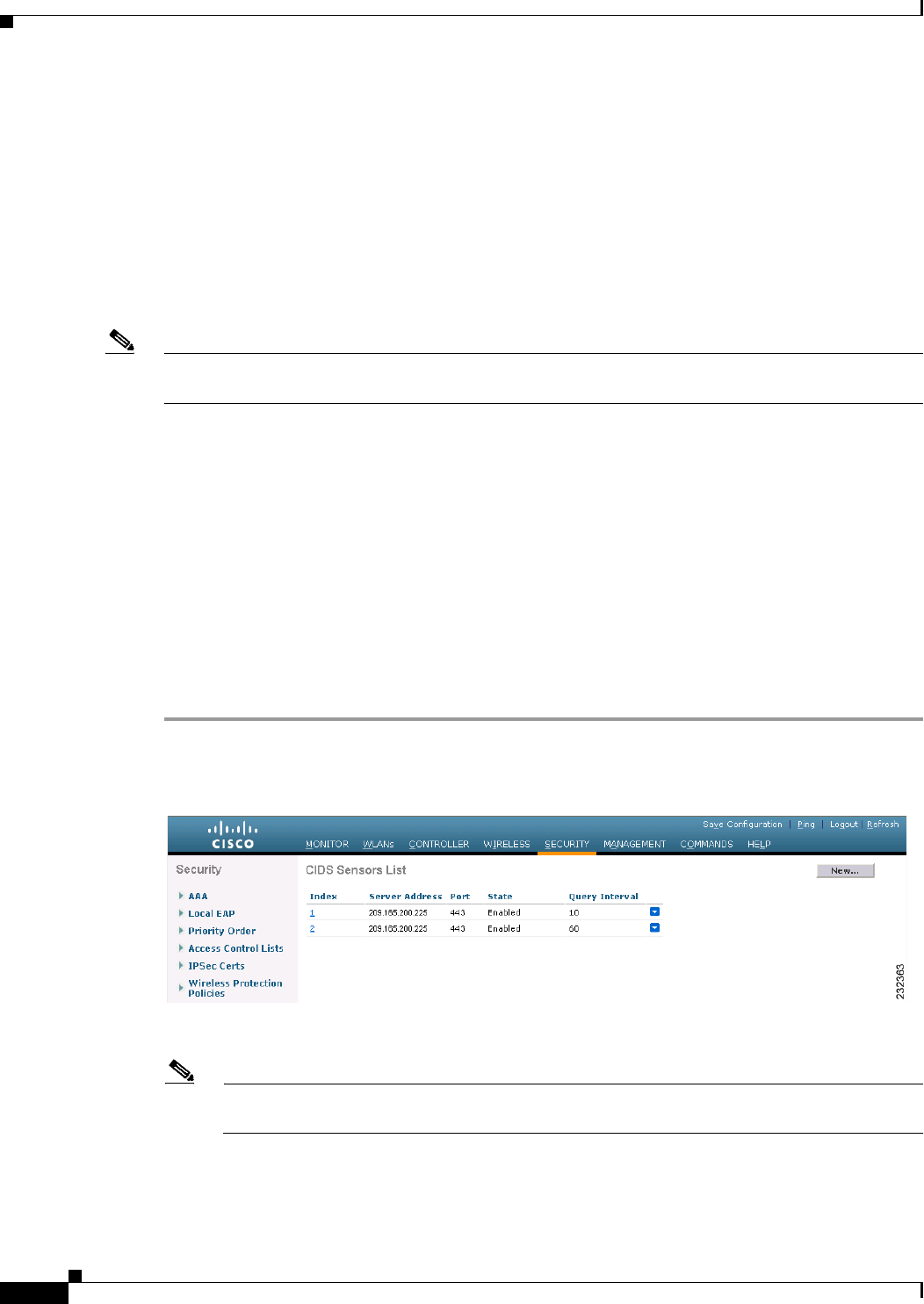
6-112
Cisco Wireless LAN Controller Configuration Guide
OL-21524-02
Chapter 6 Configuring Security Solutions
Configuring IDS
Configuring IDS
The Cisco intrusion detection system/intrusion prevention system (CIDS/IPS) instructs controllers to
block certain clients from accessing the wireless network when attacks involving these clients are
detected at Layer 3 through Layer 7. This system offers significant network protection by helping to
detect, classify, and stop threats including worms, spyware/adware, network viruses, and application
abuse. Two methods are available to detect potential attacks:
• IDS sensors
• IDS signatures
Note The Cisco wireless intrusion prevention system (wIPS) is also supported on the controller through WCS.
See the “Configuring wIPS” section on page 6-128 for more information.
Configuring IDS Sensors
You can configure IDS sensors to detect various types of IP-level attacks in your network. When the
sensors identify an attack, they can alert the controller to shun the offending client. When you add a new
IDS sensor, you register the controller with that IDS sensor so that the controller can query the sensor
to get the list of shunned clients. You can configure IDS sensor registration through either the GUI or
the CLI.
Using the GUI to Configure IDS Sensors
To configure IDS sensors using the controller GUI, follow these steps:
Step 1 Choose Security > Advanced > CIDs > Sensors to open the CIDS Sensors List page (see Figure 6-54).
Figure 6-54 CIDS Sensors List Page
This page lists all of the IDS sensors that have been configured for this controller.
Note If you want to delete an existing sensor, hover your cursor over the blue drop-down arrow for
that sensor and choose Remove.
Step 2 Add an IDS sensor to the list by clicking New. The CIDS Sensor Add page appears (see Figure 6-55).
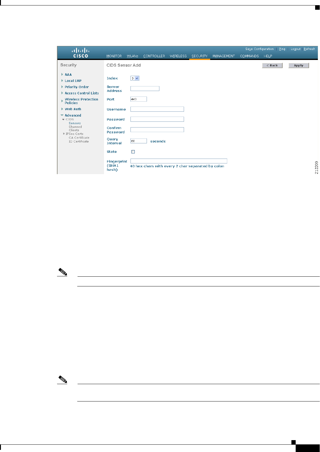
6-113
Cisco Wireless LAN Controller Configuration Guide
OL-21524-02
Chapter 6 Configuring Security Solutions
Configuring IDS
Figure 6-55 CIDS Sensor Add Page
Step 3 The controller supports up to five IDS sensors. From the Index drop-down list, choose a number
(between 1 and 5) to determine the sequence in which the controller consults the IDS sensors. For
example, if you choose 1, the controller consults this IDS sensor first.
Step 4 In the Server Address text box, enter the IP address of your IDS server.
Step 5 The Port text box contains the number of the HTTPS port through which the controller is to communicate
with the IDS sensor. We recommend that you set this parameter to 443 because the sensor uses this value
to communicate by default.
The default value is 443 and the range is 1 to 65535.
Step 6 In the Username text box, enter the name that the controller uses to authenticate to the IDS sensor.
Note This username must be configured on the IDS sensor and have at least a read-only privilege.
Step 7 In the Password and Confirm Password text boxes, enter the password that the controller uses to
authenticate to the IDS sensor.
Step 8 In the Query Interval text box, enter the time (in seconds) for how often the controller should query the
IDS server for IDS events.
The default is 60 seconds and the range is 10 to 3600 seconds.
Step 9 Select the State check box to register the controller with this IDS sensor or unselected this check box to
disable registration. The default value is disabled.
Step 10 Enter a 40-hexadecimal-character security key in the Fingerprint text box. This key is used to verify the
validity of the sensor and is used to prevent security attacks.
Note Make sure you include colons that appear between every two bytes within the key. For example,
enter AA:BB:CC:DD.
Step 11 Click Apply. Your new IDS sensor appears in the list of sensors on the CIDS Sensors List page.

6-114
Cisco Wireless LAN Controller Configuration Guide
OL-21524-02
Chapter 6 Configuring Security Solutions
Configuring IDS
Step 12 Click Save Configuration to save your changes.
Using the CLI to Configure IDS Sensors
To configure IDS sensors using the controller CLI, follow these steps:
Step 1 Add an IDS sensor by entering this command:
config wps cids-sensor add index ids_ip_address username password
The index parameter determines the sequence in which the controller consults the IDS sensors. The
controller supports up to five IDS sensors. Enter a number (between 1 and 5) to determine the priority
of this sensor. For example, if you enter 1, the controller consults this IDS sensor first.
Note The username must be configured on the IDS sensor and have at least a read-only privilege.
Step 2 (Optional) Specify the number of the HTTPS port through which the controller is to communicate with
the IDS sensor by entering this command:
config wps cids-sensor port index port_number
For the port-number parameter, you can enter a value between 1 and 65535. The default value is 443.
This step is optional because we recommend that you use the default value of 443. The sensor uses this
value to communicate by default.
Step 3 Specify how often the controller should query the IDS server for IDS events by entering this command:
config wps cids-sensor interval index interval
For the interval parameter, you can enter a value between 10 and 3600 seconds. The default value is 60
seconds.
Step 4 Enter a 40-hexadecimal-character security key used to verify the validity of the sensor by entering this
command:
config wps cids-sensor fingerprint index sha1 fingerprint
You can get the value of the fingerprint by entering show tls fingerprint on the sensor’s console.
Note Make sure to include the colons that appear between every two bytes within the key (for
example, AA:BB:CC:DD).
Step 5 Enable or disable this controller’s registration with an IDS sensor by entering this command:
config wps cids-sensor {enable | disable} index
Step 6 Enable or disable protection from DoS attacks by entering this command:
config wps auto-immune {enable | disable}
The default value is disabled.

6-115
Cisco Wireless LAN Controller Configuration Guide
OL-21524-02
Chapter 6 Configuring Security Solutions
Configuring IDS
Note A potential attacker can use specially crafted packets to mislead the IDS into treating a
legitimate client as an attacker. It causes the controller to wrongly disconnect this legitimate
client and launches a DoS attack. The auto-immune feature, when enabled, is designed to protect
against such attacks. However, conversations using Cisco 792x phones might be interrupted
intermittently when the auto-immune feature is enabled. If you experience frequent disruptions
when using 792x phones, you might want to disable this feature.
Step 7 Save your settings by entering this command:
save config
Step 8 See the IDS sensor configuration by entering one of these commands:
• show wps cids-sensor summary
• show wps cids-sensor detail index
The second command provides more information than the first.
Step 9 See the auto-immune configuration setting by entering this command:
show wps summary
Information similar to the following appears:
Auto-Immune
Auto-Immune.................................... Disabled
Client Exclusion Policy
Excessive 802.11-association failures.......... Enabled
Excessive 802.11-authentication failures....... Enabled
Excessive 802.1x-authentication................ Enabled
IP-theft....................................... Enabled
Excessive Web authentication failure........... Enabled
Signature Policy
Signature Processing........................... Enabled
Step 10 Obtain debug information regarding IDS sensor configuration by entering this command:
debug wps cids enable
Note If you ever want to delete or change the configuration of a sensor, you must first disable it by entering
the config wps cids-sensor disable index command. To delete the sensor, enter the config wps
cids-sensor delete index command.
Viewing Shunned Clients
When an IDS sensor detects a suspicious client, it alerts the controller to shun this client. The shun entry
is distributed to all controllers within the same mobility group. If the client to be shunned is currently
joined to a controller in this mobility group, the anchor controller adds this client to the dynamic
exclusion list, and the foreign controller removes the client. The next time that the client tries to connect
to a controller, the anchor controller rejects the handoff and informs the foreign controller that the client
is being excluded. See Chapter 14, “Configuring Mobility Groups,” for more information on mobility
groups.
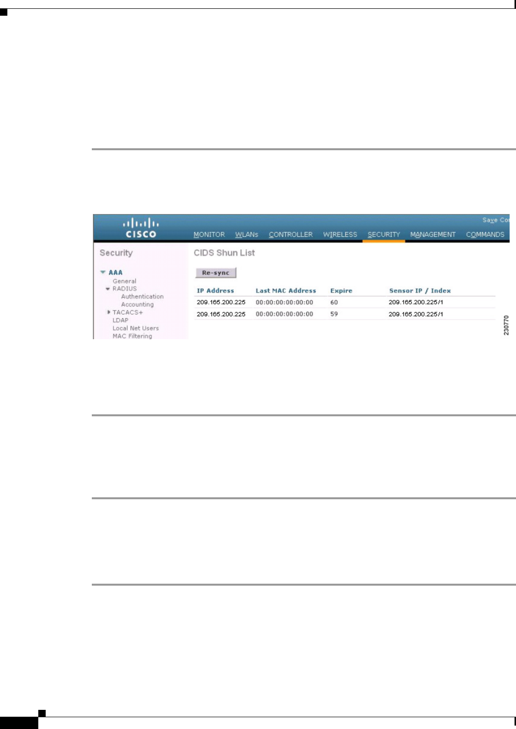
6-116
Cisco Wireless LAN Controller Configuration Guide
OL-21524-02
Chapter 6 Configuring Security Solutions
Configuring IDS
You can view the list of clients that the IDS sensors have identified to be shunned through either the GUI
or the CLI.
Using the GUI to View Shunned Clients
To view the list of clients that the IDS sensors have identified to be shunned using the controller GUI,
follow these steps:
Step 1 Choose Security > Advanced > CIDS > Shunned Clients to open the CIDS Shun List page (see
Figure 6-56).
Figure 6-56 CIDS Shun List Page
This page shows the IP address and MAC address of each shunned client, the length of time that the
client’s data packets should be blocked by the controller as requested by the IDS sensor, and the IP
address of the IDS sensor that discovered the client.
Step 2 Click Re-sync to purge and reset the list as desired.
Using the CLI to View Shunned Clients
To view the list of clients that the IDS sensors have identified to be shunned using the controller CLI,
follow these steps:
Step 1 View the list of clients to be shunned by entering this command:
show wps shun-list
Step 2 Force the controller to synchronize with other controllers in the mobility group for the shun list by
entering this command:
config wps shun-list re-sync
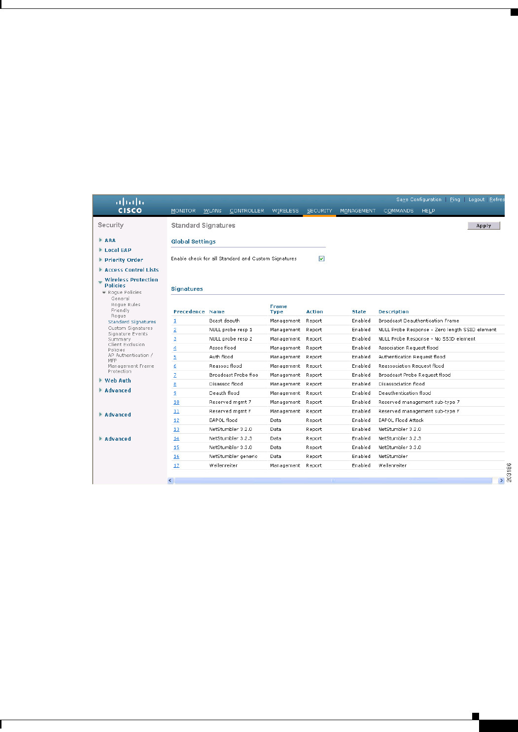
6-117
Cisco Wireless LAN Controller Configuration Guide
OL-21524-02
Chapter 6 Configuring Security Solutions
Configuring IDS
Configuring IDS Signatures
You can configure IDS signatures, or bit-pattern matching rules used to identify various types of attacks
in incoming 802.11 packets, on the controller. When the signatures are enabled, the access points joined
to the controller perform signature analysis on the received 802.11 data or management frames and
report any discrepancies to the controller. If an attack is detected, appropriate mitigation is initiated.
Cisco supports 17 standard signatures on the controller as shown on the Standard Signatures page (see
Figure 6-57).
Figure 6-57 Standard Signatures Page
These signatures are divided into six main groups. The first four groups contain management signatures,
and the last two groups contain data signatures.
• Broadcast deauthentication frame signatures—During a broadcast deauthentication frame attack, a
hacker sends an 802.11 deauthentication frame to the broadcast MAC destination address of another
client. This attack causes the destination client to disassociate from the access point and lose its
connection. If this action is repeated, the client experiences a denial of service. When the broadcast
deauthentication frame signature (precedence 1) is used to detect such an attack, the access point
listens for clients transmitting broadcast deauthentication frames that match the characteristics of
the signature. If the access point detects such an attack, it alerts the controller. Depending on how
your system is configured, the offending device is contained so that its signals no longer interfere
with authorized clients, or the controller forwards an immediate alert to the system administrator for
further action, or both.

6-118
Cisco Wireless LAN Controller Configuration Guide
OL-21524-02
Chapter 6 Configuring Security Solutions
Configuring IDS
• NULL probe response signatures—During a NULL probe response attack, a hacker sends a NULL
probe response to a wireless client adapter. As a result, the client adapter locks up. When a NULL
probe response signature is used to detect such an attack, the access point identifies the wireless
client and alerts the controller. The NULL probe response signatures are as follows:
–
NULL probe resp 1 (precedence 2)
–
NULL probe resp 2 (precedence 3)
• Management frame flood signatures—During a management frame flood attack, a hacker floods an
access point with 802.11 management frames. The result is a denial of service to all clients
associated or attempting to associate to the access point. This attack can be implemented with
different types of management frames: association requests, authentication requests, reassociation
requests, probe requests, disassociation requests, deauthentication requests, and reserved
management subtypes.
When a management frame flood signature is used to detect such an attack, the access point
identifies management frames matching the entire characteristic of the signature. If the frequency
of these frames is greater than the value of the frequency set in the signature, an access point that
hears these frames triggers an alarm. The controller generates a trap and forwards it to WCS.
The management frame flood signatures are as follows:
–
Assoc flood (precedence 4)
–
Auth flood (precedence 5)
–
Reassoc flood (precedence 6)
–
Broadcast probe flood (precedence 7)
–
Disassoc flood (precedence 8)
–
Deauth flood (precedence 9)
–
Reserved mgmt 7 (precedence 10)
–
Reserved mgmt F (precedence 11)
The reserved management frame signatures 7 and F are reserved for future use.
• Wellenreiter signature—Wellenreiter is a wireless LAN scanning and discovery utility that can
reveal access point and client information. When the Wellenreiter signature (precedence 17) is used
to detect such an attack, the access point identifies the offending device and alerts the controller.
• EAPOL flood signature—During an EAPOL flood attack, a hacker floods the air with EAPOL
frames that contain 802.1X authentication requests. As a result, the 802.1X authentication server
cannot respond to all of the requests and fails to send successful authentication responses to valid
clients. The result is a denial of service to all affected clients. When the EAPOL flood signature
(precedence 12) is used to detect such an attack, the access point waits until the maximum number
of allowed EAPOL packets is exceeded. It then alerts the controller and proceeds with the
appropriate mitigation.
• NetStumbler signatures—NetStumbler is a wireless LAN scanning utility that reports access point
broadcast information (such as operating channel, RSSI information, adapter manufacturer name,
SSID, WEP status, and the latitude and longitude of the device running NetStumbler when a GPS is
attached). If NetStumbler succeeds in authenticating and associating to an access point, it sends a
data frame with the following strings, depending on the NetStumbler version:
Version String
3.2.0 “Flurble gronk bloopit, bnip Frundletrune”

6-119
Cisco Wireless LAN Controller Configuration Guide
OL-21524-02
Chapter 6 Configuring Security Solutions
Configuring IDS
When a NetStumbler signature is used to detect such an attack, the access point identifies the
offending device and alerts the controller. The NetStumbler signatures are as follows:
–
NetStumbler 3.2.0 (precedence 13)
–
NetStumbler 3.2.3 (precedence 14)
–
NetStumbler 3.3.0 (precedence 15)
–
NetStumbler generic (precedence 16)
A standard signature file exists on the controller by default. You can upload this signature file from the
controller, or you can create a custom signature file and download it to the controller or modify the
standard signature file to create a custom signature. You can configure signatures through either the GUI
or the CLI.
Using the GUI to Configure IDS Signatures
To configure signatures using the controller GUI, follow these steps:
• Uploading or downloading IDS signatures, page 6-119
• Enabling or disabling IDS signatures, page 6-121
• Viewing IDS signature events, page 6-123
Using the GUI to Upload or Download IDS Signatures
To upload or download IDS signatures using the controller GUI, follow these steps:
Step 1 If desired, create your own custom signature file.
Step 2 Make sure that you have a Trivial File Transfer Protocol (TFTP) server available. Follow these
guidelines when setting up a TFTP server:
• If you are downloading through the service port, the TFTP server must be on the same subnet as the
service port because the service port is not routable, or you must create static routes on the
controller.
• If you are downloading through the distribution system network port, the TFTP server can be on the
same or a different subnet because the distribution system port is routable.
• A third-party TFTP server cannot run on the same computer as the Cisco WCS because the WCS
built-in TFTP server and the third-party TFTP server require the same communication port.
Step 3 If you are downloading a custom signature file (*.sig), copy it to the default directory on your TFTP
server.
Step 4 Choose Commands to open the Download File to Controller page (see Figure 6-58).
3.2.3 “All your 802.11b are belong to us”
3.3.0 Sends white spaces
Version String

6-120
Cisco Wireless LAN Controller Configuration Guide
OL-21524-02
Chapter 6 Configuring Security Solutions
Configuring IDS
Figure 6-58 Download File to Controller Page
Step 5 Perform one of the following:
• If you want to download a custom signature file to the controller, choose Signature File from the
File Type drop-down list on the Download File to Controller page.
• If you want to upload a standard signature file from the controller, choose Upload File and then
Signature File from the File Type drop-down list on the Upload File from Controller page.
Step 6 From the Transfer Mode drop-down list, choose TFTP or FTP.
Step 7 In the IP Address text box, enter the IP address of the TFTP or FTP server.
Step 8 If you are downloading the signature file using a TFTP server, enter the maximum number of times that
the controller should attempt to download the signature file in the Maximum retries text box.
The range is 1 to 254 and the default value is 10.
Step 9 If you are downloading the signature file using a TFTP server, enter the amount of time in seconds before
the controller times out while attempting to download the signature file in the Timeout text box.
The range is 1 to 254 seconds and the default is 6 seconds.
Step 10 In the File Path text box, enter the path of the signature file to be downloaded or uploaded. The default
value is “/.”
Step 11 In the File Name text box, enter the name of the signature file to be downloaded or uploaded.
Note When uploading signatures, the controller uses the filename that you specify as a base name and
then adds “_std.sig” and “_custom.sig” to it in order to upload both standard and custom
signature files to the TFTP server. For example, if you upload a signature file called “ids1,” the
controller automatically generates and uploads both ids1_std.sig and ids1_custom.sig to the
TFTP server. If desired, you can then modify ids1_custom.sig on the TFTP server (making sure
to set “Revision = custom”) and download it by itself.
Step 12 If you are using an FTP server, follow these steps:
a. In the Server Login Username text box, enter the username to log into the FTP server.
b. In the Server Login Password text box, enter the password to log into the FTP server.
c. In the Server Port Number text box, enter the port number on the FTP server through which the
download occurs. The default value is 21.
Step 13 Choose Download to download the signature file to the controller or Upload to upload the signature file
from the controller.
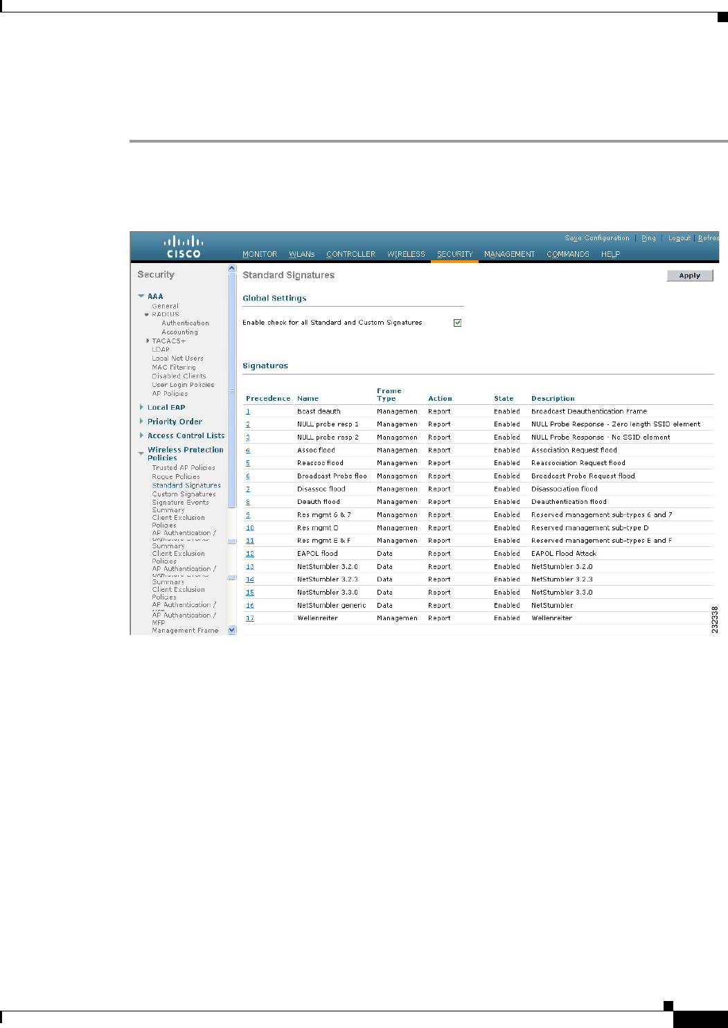
6-121
Cisco Wireless LAN Controller Configuration Guide
OL-21524-02
Chapter 6 Configuring Security Solutions
Configuring IDS
Using the GUI to Enable or Disable IDS Signatures
To enable or disable IDS signatures using the controller GUI, follow these steps:
Step 1 Choose Security > Wireless Protection Policies > Standard Signatures or Custom Signatures to open
the Standard Signatures page (see Figure 6-59) or the Custom Signatures page.
Figure 6-59 Standard Signatures Page
The Standard Signatures page shows the list of Cisco-supplied signatures that are currently on the
controller. The Custom Signatures page shows the list of customer-supplied signatures that are currently
on the controller. This page shows the following information for each signature:
• The order, or precedence, in which the controller performs the signature checks.
• The name of the signature, which specifies the type of attack that the signature is trying to detect.
• The frame type on which the signature is looking for a security attack. The possible frame types are
data and management.
• The action that the controller is directed to take when the signature detects an attack. The possible
actions are None and Report.
• The state of the signature, which indicates whether the signature is enabled to detect security attacks.
• A description of the type of attack that the signature is trying to detect.
Step 2 Perform one of the following:
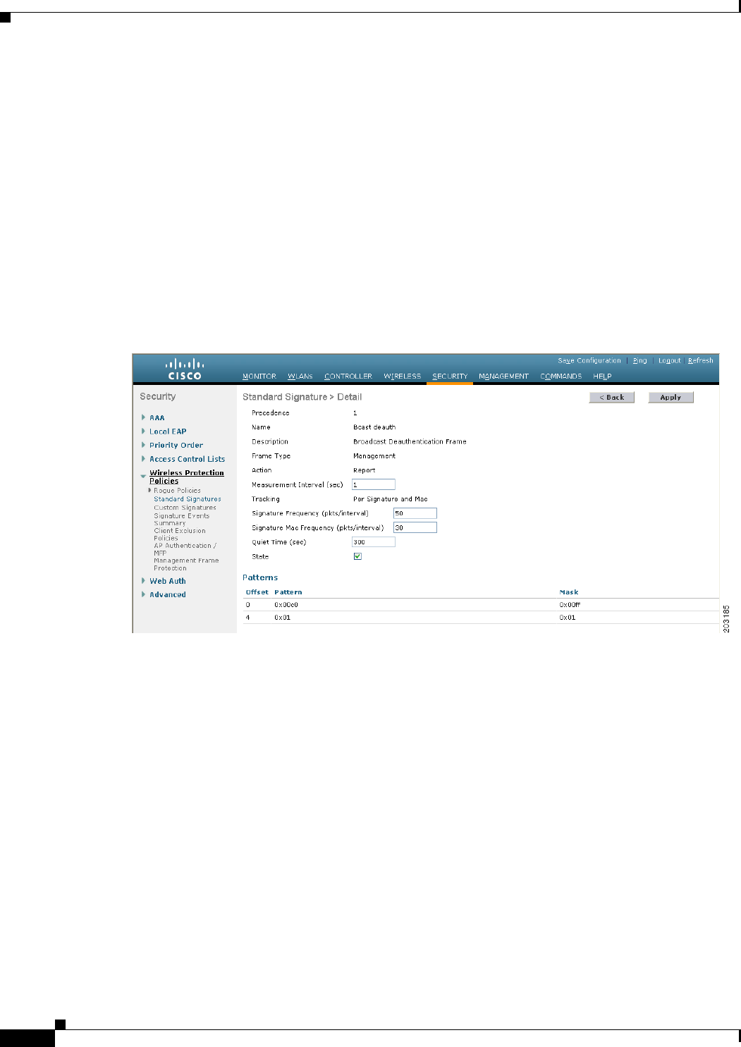
6-122
Cisco Wireless LAN Controller Configuration Guide
OL-21524-02
Chapter 6 Configuring Security Solutions
Configuring IDS
• If you want to allow all signatures (both standard and custom) whose individual states are set to
Enabled to remain enabled, select the Enable Check for All Standard and Custom Signatures
check box at the top of either the Standard Signatures page or the Custom Signatures page. The
default value is enabled (or selected). When the signatures are enabled, the access points joined to
the controller perform signature analysis on the received 802.11 data or management frames and
report any discrepancies to the controller.
• If you want to disable all signatures (both standard and custom) on the controller, unselect the
Enable Check for All Standard and Custom Signatures check box. If you unselected this check
box, all signatures are disabled, even the ones whose individual states are set to Enabled.
Step 3 Click Apply to commit your changes.
Step 4 Click the precedence number of the desired signature to enable or disable an individual signature. The
Standard Signature (or Custom Signature) > Detail page appears (see Figure 6-60).
Figure 6-60 Standard Signature > Detail Page
This page shows much of the same information as the Standard Signatures and Custom Signatures pages
but provides these additional details:
• The tracking method used by the access points to perform signature analysis and report the results
to the controller. The possible values are as follows:
–
Per Signature—Signature analysis and pattern matching are tracked and reported on a
per-signature and per-channel basis.
–
Per MAC—Signature analysis and pattern matching are tracked and reported separately for
individual client MAC addresses on a per-channel basis.
–
Per Signature and MAC—Signature analysis and pattern matching are tracked and reported on
a per-signature and per-channel basis as well as on a per-MAC-address and per-channel basis.
• The pattern that is being used to detect a security attack
Step 5 In the Measurement Interval text box, enter the number of seconds that must elapse before the signature
frequency threshold is reached within the configured interval. The range is 1 to 3600 seconds, and the
default value varies per signature.
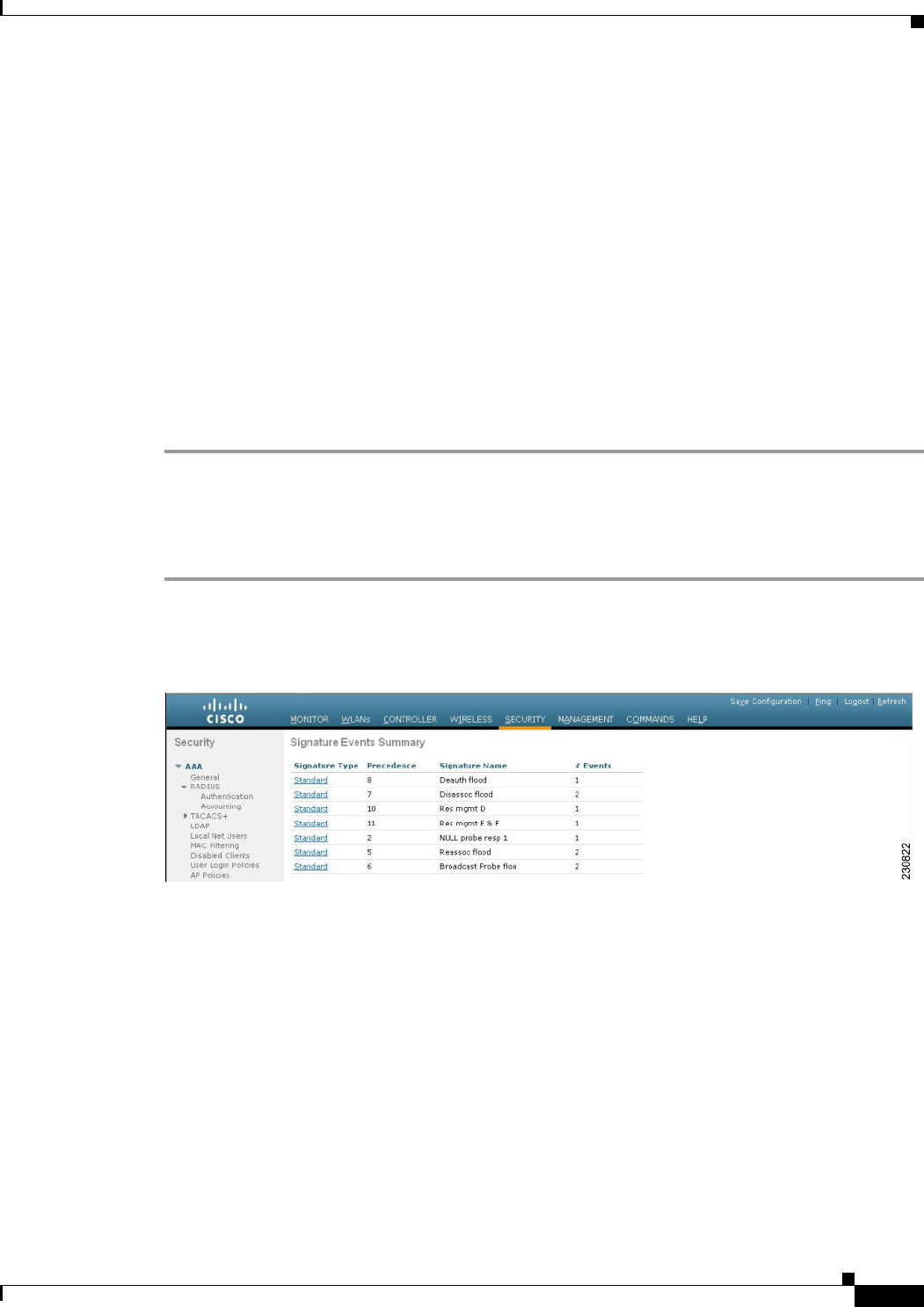
6-123
Cisco Wireless LAN Controller Configuration Guide
OL-21524-02
Chapter 6 Configuring Security Solutions
Configuring IDS
Step 6 In the Signature Frequency text box, enter the number of matching packets per interval that must be
identified at the individual access point level before an attack is detected. The range is 1 to 32,000
packets per interval, and the default value varies per signature.
Step 7 In the Signature MAC Frequency text box, enter the number of matching packets per interval that must
be identified per client per access point before an attack is detected. The range is 1 to 32,000 packets per
interval, and the default value varies per signature.
Step 8 In the Quiet Time text box, enter the length of time (in seconds) after which no attacks have been
detected at the individual access point level and the alarm can stop. The range is 60 to 32,000 seconds,
and the default value varies per signature.
Step 9 Select the State check box to enable this signature to detect security attacks or unselect it to disable this
signature. The default value is enabled (or selected).
Step 10 Click Apply to commit your changes. The Standard Signatures or Custom Signatures page reflects the
signature’s updated state.
Step 11 Click Save Configuration to save your changes.
Using the GUI to View IDS Signature Events
To view signature events using the controller GUI, follow these steps:
Step 1 Choose Security > Wireless Protection Policies > Signature Events Summary to open the Signature
Events Summary page (see Figure 6-61).
Figure 6-61 Signature Events Summary Page
This page shows the number of attacks detected by the enabled signatures.
Step 2 Click the signature type link for that signature to see more information on the attacks detected by a
particular signature. The Signature Events Detail page appears (see Figure 6-62).
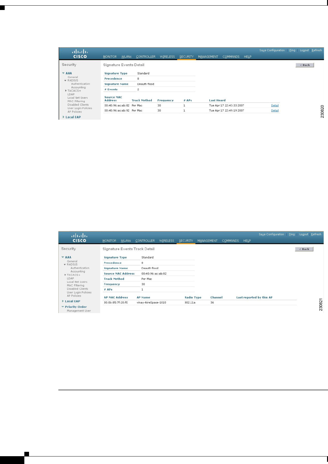
6-124
Cisco Wireless LAN Controller Configuration Guide
OL-21524-02
Chapter 6 Configuring Security Solutions
Configuring IDS
Figure 6-62 Signature Events Detail Page
This page shows the following information:
• The MAC addresses of the clients identified as attackers
• The method used by the access point to track the attacks
• The number of matching packets per second that were identified before an attack was detected
• The number of access points on the channel on which the attack was detected
• The day and time when the access point detected the attack
Step 3 Click the Detail link for that attack to see more information for a particular attack. The Signature Events
Track Detail page appears (see Figure 6-63).
Figure 6-63 Signature Events Track Detail Page
This page shows the following information:
• The MAC address of the access point that detected the attack
• The name of the access point that detected the attack
• The type of radio (802.11a or 802.11b/g) used by the access point to detect the attack
• The radio channel on which the attack was detected
• The day and time when the access point reported the attack
Using the CLI to Configure IDS Signatures
To configure IDS signatures using the controller CLI, follow these steps:

6-125
Cisco Wireless LAN Controller Configuration Guide
OL-21524-02
Chapter 6 Configuring Security Solutions
Configuring IDS
Step 1 If desired, create your own custom signature file.
Step 2 Make sure that you have a TFTP server available. See the guidelines for setting up a TFTP server in
Step 2 of the “Using the GUI to Upload or Download IDS Signatures” section on page 6-119.
Step 3 Copy the custom signature file (*.sig) to the default directory on your TFTP server.
Step 4 Specify the download or upload mode by entering the transfer {download | upload} mode tftp
command.
Step 5 Specify the type of file to be downloaded or uploaded by entering the transfer {download | upload}
datatype signature command.
Step 6 Specify the IP address of the TFTP server by entering the transfer {download | upload} serverip
tftp-server-ip-address command.
Note Some TFTP servers require only a forward slash (/) as the TFTP server IP address, and the TFTP
server automatically determines the path to the correct directory.
Step 7 Specify the download or upload path by entering the transfer {download | upload} path
absolute-tftp-server-path-to-file command.
Step 8 Specify the file to be downloaded or uploaded by entering the transfer {download | upload} filename
filename.sig command.
Note When uploading signatures, the controller uses the filename you specify as a base name and then
adds “_std.sig” and “_custom.sig” to it in order to upload both standard and custom signature
files to the TFTP server. For example, if you upload a signature file called “ids1,” the controller
automatically generates and uploads both ids1_std.sig and ids1_custom.sig to the TFTP server.
If desired, you can then modify ids1_custom.sig on the TFTP server (making sure to set
“Revision = custom”) and download it by itself.
Step 9 Enter the transfer {download | upload} start command and answer y to the prompt to confirm the
current settings and start the download or upload.
Step 10 Specify the number of seconds that must elapse before the signature frequency threshold is reached
within the configured interval by entering this command:
config wps signature interval signature_id interval
where signature_id is a number used to uniquely identify a signature. The range is 1 to 3600 seconds,
and the default value varies per signature.
Step 11 Specify the number of matching packets per interval that must be identified at the individual access point
level before an attack is detected by entering this command:
config wps signature frequency signature_id frequency
The range is 1 to 32,000 packets per interval, and the default value varies per signature.
Step 12 Specify the number of matching packets per interval that must be identified per client per access point
before an attack is detected by entering this command:
config wps signature mac-frequency signature_id mac_frequency
The range is 1 to 32,000 packets per interval, and the default value varies per signature.
Step 13 Specify the length of time (in seconds) after which no attacks have been detected at the individual access
point level and the alarm can stop by entering by entering this command:

6-126
Cisco Wireless LAN Controller Configuration Guide
OL-21524-02
Chapter 6 Configuring Security Solutions
Configuring IDS
config wps signature quiet-time signature_id quiet_time
The range is 60 to 32,000 seconds, and the default value varies per signature.
Step 14 Perform one of the following:
• To enable or disable an individual IDS signature, enter this command:
config wps signature {standard | custom} state signature_id {enable | disable}
• To enable or disable IDS signature processing, which enables or disables the processing of all IDS
signatures, enter this command:
config wps signature {enable | disable}
Note If IDS signature processing is disabled, all signatures are disabled, regardless of the state
configured for individual signatures.
Step 15 Save your changes by entering this command:
save config
Step 16 If desired, you can reset a specific signature or all signatures to default values. To do so, enter this
command:
config wps signature reset {signature_id | all}
Note You can reset signatures to default values only through the controller CLI.
Using the CLI to View IDS Signature Events
To view signature events using the controller CLI, use these commands:
• See whether IDS signature processing is enabled or disabled on the controller by entering this
command:
show wps summary
Information similar to the following appears:
Auto-Immune
Auto-Immune.................................... Disabled
Client Exclusion Policy
Excessive 802.11-association failures.......... Enabled
Excessive 802.11-authentication failures....... Enabled
Excessive 802.1x-authentication................ Enabled
IP-theft....................................... Enabled
Excessive Web authentication failure........... Enabled
Signature Policy
Signature Processing........................... Enabled
Note If IDS signature processing is disabled, all signatures are disabled, regardless of the state
configured for individual signatures.

6-127
Cisco Wireless LAN Controller Configuration Guide
OL-21524-02
Chapter 6 Configuring Security Solutions
Configuring IDS
• See individual summaries of all of the standard and custom signatures installed on the controller by
entering this command:
show wps signature summary
Information similar to the following appears:
Signature-ID..................................... 1
Precedence....................................... 1
Signature Name................................... Bcast deauth
Type............................................. standard
FrameType........................................ management
State............................................ enabled
Action........................................... report
Tracking......................................... per Signature and Mac
Signature Frequency.............................. 50 pkts/interval
Signature Mac Frequency.......................... 30 pkts/interval
Interval......................................... 1 sec
Quiet Time....................................... 300 sec
Description...................................... Broadcast Deauthentication Frame
Patterns:
0(Header):0x00c0:0x00ff
4(Header):0x01:0x01
• See the number of attacks detected by the enabled signatures by entering this command:
show wps signature events summary
Information similar to the following appears:
Precedence Signature Name Type # Events
---------- ------------------ ----- -----------
1 Bcast deauth Standard 2
2 NULL probe resp 1 Standard 1
• See more information on the attacks detected by a particular standard or custom signature by
entering this command:
show wps signature events {standard | custom} precedence# summary
Information similar to the following appears:
Precedence....................................... 1
Signature Name................................... Bcast deauth
Type............................................. Standard
Number of active events....................... 2
Source MAC Addr Track Method Frequency No. APs Last Heard
----------------- ------------ --------- -------- ------------------------
00:01:02:03:04:01 Per Signature 4 3 Tue Dec 6 00:17:44 2005
00:01:02:03:04:01 Per Mac 6 2 Tue Dec 6 00:30:04 2005
• See information on attacks that are tracked by access points on a per-signature and per-channel basis
by entering this command:
show wps signature events {standard | custom} precedence# detailed per-signature source_mac
• See information on attacks that are tracked by access points on an individual-client basis (by MAC
address) by entering this command:
show wps signature events {standard | custom} precedence# detailed per-mac source_mac
Information similar to the following appears:
Source MAC....................................... 00:01:02:03:04:01
Precedence....................................... 1
Signature Name................................... Bcast deauth

6-128
Cisco Wireless LAN Controller Configuration Guide
OL-21524-02
Chapter 6 Configuring Security Solutions
Configuring wIPS
Type............................................. Standard
Track............................................ Per Mac
Frequency........................................ 6
Reported By
AP 1
MAC Address.............................. 00:0b:85:01:4d:80
Name..................................... Test_AP_1
Radio Type............................... 802.11bg
Channel.................................. 4
Last reported by this AP................. Tue Dec 6 00:17:49 2005
AP 2
MAC Address.............................. 00:0b:85:26:91:52
Name..................................... Test_AP_2
Radio Type............................... 802.11bg
Channel.................................. 6
Last reported by this AP................. Tue Dec 6 00:30:04 2005
Configuring wIPS
The Cisco Adaptive wireless intrusion prevention system (wIPS) is an advanced approach to wireless
threat detection and performance management. It combines network traffic analysis, network device and
topology information, signature-based techniques, and anomaly detection to deliver highly accurate and
complete wireless threat prevention. With a fully infrastructure-integrated solution, you can continually
monitor wireless traffic on both the wired and wireless networks and use that network intelligence to
analyze attacks from many sources to more accurately pinpoint and proactively prevent attacks rather
than waiting until damage or exposure has occurred.
The Cisco Adaptive wIPS is enabled by the Cisco 3300 Series Mobility Services Engine (MSE), which
centralizes the processing of intelligence collected by the continuous monitoring of Cisco Aironet access
points. With Cisco Adaptive wIPS functionalities and WCS integration into the MSE, the wIPS service
can configure, monitor, and report wIPS policies and alarms.
Note If your wIPS deployment consists of a controller, access point, and MSE, you must set all the three
entities to the UTC time zone.
The Cisco Adaptive wIPS is not configured on the controller. Instead, WCS forwards the profile
configuration to the wIPS service, which forwards the profile to the controller. The profile is stored in
flash memory on the controller and sent to access points when they join the controller. When an access
point disassociates and joins another controller, it receives the wIPS profile from the new controller.
Starting release 7.0.116.0, the regular local mode or H-REAP mode access point has been extended with
a subset of Wireless Intrusion Prevention System (wIPS) capabilities. This feature enables you to deploy
your access points to provide protection without needing a separate overlay network.
Local mode or Hybrid REAP mode access points with a subset of wIPS capabilities is referred to as
Enhanced Local Mode access point or just ELM AP. You can configure an access point to work in wIPS
mode if the access point is in any of the following modes:
• Monitor
• Local
• Hybrid REAP
Note wIPS ELM is not supported on 1130 and 1240 access points.

6-129
Cisco Wireless LAN Controller Configuration Guide
OL-21524-02
Chapter 6 Configuring Security Solutions
Configuring wIPS
wIPS ELM has limited capability of detecting off-channel alarms. The access point periodically goes
off-channel, and monitors the non-serving channels for a short duration, and triggers alarms if any attack
is detected on the channel. But the off-channel alarm detection is best effort and it takes longer time to
detect attacks and trigger alarms, which might cause the ELM AP intermittently detect an alarm and
clear it because it is not visible. Access points in any of the above modes can periodically send alarms
based on the policy profile to the wIPS service through the controller. The wIPS service stores and
processes the alarms and generates SNMP traps. WCS configures its IP address as a trap destination to
receive SNMP traps from the MSE.
Note In all of the above cases, the controller functions solely as a forwarding device.
Note For more information on the Cisco Adaptive wIPS, see the Cisco Wireless Control System Configuration
Guide, Release 7.0.172.0 and the Cisco 3300 Series Mobility Services Engine Configuration Guide,
Release 7.0.201.0.
Using the GUI to Configure wIPS on an Access Point
To configure wIPS on an access point using the controller GUI, follow these steps:
Step 1 Choose Wireless > Access Points > All APs > access point name.
Step 2 Set the AP Mode parameter. To configure an access point for wIPS, you must choose one of the
following modes from the AP Mode drop-down list:
• Local
• H-REAP
• Monitor
Step 3 Set the AP Sub Mode to wIPS by choosing wIPS from the AP Sub Mode drop-down list.
Step 4 Click Apply.
Using the CLI to Configure wIPS on an Access Point
To configure wIPS on an access point using the controller CLI, follow these steps:
Step 1 Configure an access point for monitor mode by entering this command:
config ap mode {monitor | local | h-reap} Cisco_AP
Note To configure an access point for wIPS, the access point must be in monitor, local, or h-reap
modes.
Step 2 Enter Y when you see the message that the access point will be rebooted if you want to continue.
Step 3 Save your changes by entering this command:

6-130
Cisco Wireless LAN Controller Configuration Guide
OL-21524-02
Chapter 6 Configuring Security Solutions
Configuring wIPS
save config
Step 4 Disable the access point radio by entering this command:
config {802.11a | 802.11b} disable Cisco_AP
Step 5 Configure the wIPS submode on the access point by entering this command:
config ap mode ap_mode submode wips Cisco_AP
Note To disable wIPS on the access point, enter the config ap mode ap_mode submode none
Cisco_AP command.
Step 6 Enable wIPS optimized channel scanning for the access point by entering this command:
config ap monitor-mode wips-optimized Cisco_AP
The access point scans each channel for 250 milliseconds. It derives the list of channels to be scanned
from the monitor configuration. You can choose one of these options:
• All—All channels supported by the access point’s radio
• Country—Only the channels supported by the access point’s country of operation
• DCA—Only the channel set used by the dynamic channel assignment (DCA) algorithm, which by
default includes all of the nonoverlapping channels allowed in the access point’s country of
operation
The 802.11a or 802.11b Monitor Channels text box in the output of the show advanced {802.11a |
802.11b} monitor command shows the monitor configuration channel set:
Default 802.11b AP monitoring
802.11b Monitor Mode........................... enable
802.11b Monitor Channels....................... Country channels
802.11b AP Coverage Interval................... 180 seconds
802.11b AP Load Interval....................... 60 seconds
802.11b AP Noise Interval...................... 180 seconds
802.11b AP Signal Strength Interval............ 60 seconds
Step 7 Reenable the access point radio by entering this command:
config {802.11a | 802.11b} enable Cisco_AP
Step 8 Save your changes by entering this command:
save config
Viewing wIPS Information
To view wIPS information using the controller CLI, use these commands:
Note You can also view the access point submode from the controller GUI. To do so, choose Wireless >
Access Points > All APs > the access point name > the Advanced tab. The AP Sub Mode text box shows
wIPS if the access point in is monitor mode and the wIPS submode is configured on the access point or
None if the access point is not in monitor mode or the access point is in monitor mode but the wIPS
submode is not configured.

6-131
Cisco Wireless LAN Controller Configuration Guide
OL-21524-02
Chapter 6 Configuring Security Solutions
Configuring wIPS
• See the wIPS submode on the access point by entering this command:
show ap config general Cisco_AP
Information similar to the following appears:
Cisco AP Identifier.............................. 3
Cisco AP Name.................................... AP1131:46f2.98ac
...
AP Mode ......................................... Monitor
Public Safety ................................... Disabled Disabled
AP SubMode ...................................... WIPS
...
• See the wIPS optimized channel scanning configuration on the access point by entering this
command:
show ap monitor-mode summary
Information similar to the following appears:
AP Name Ethernet MAC Status Scanning Channel List
------------------ -------------------- ---------- ------------------------
AP1131:46f2.98ac 00:16:46:f2:98:ac wIPS 1, 6, NA, NA
• See the wIPS configuration forwarded by WCS to the controller by entering this command:
show wps wips summary
Information similar to the following appears:
Policy Name.............. Default
Policy Version.......... 3
• See the current state of wIPS operation on the controller by entering this command:
show wps wips statistics
Information similar to the following appears:
Policy Assignment Requests............ 1
Policy Assignment Responses........... 1
Policy Update Requests................ 0
Policy Update Responses............... 0
Policy Delete Requests................ 0
Policy Delete Responses............... 0
Alarm Updates......................... 13572
Device Updates........................ 8376
Device Update Requests................ 0
Device Update Responses............... 0
Forensic Updates...................... 1001
Invalid WIPS Payloads................. 0
Invalid Messages Received............. 0
NMSP Transmitted Packets.............. 22950
NMSP Transmit Packets Dropped......... 0
NMSP Largest Packet................... 1377
• Clear the wIPS statistics on the controller by entering this command:
clear stats wps wips

6-132
Cisco Wireless LAN Controller Configuration Guide
OL-21524-02
Chapter 6 Configuring Security Solutions
Configuring Web Auth Proxy
Configuring Web Auth Proxy
This feature enables clients that have manual web proxy enabled in the browser to facilitate
authentication with the controller. If the user's browser is configured with manual proxy settings with a
configured port number as 8080 or 3128 and if the client requests any URL, the controller responds with
a web page prompting the user to change the Internet proxy settings to automatically detect the proxy
settings so that the browser’s manual proxy settings information does not get lost. After enabling this
settings, the user can get access to the network through the web authentication policy. This functionality
is given for port 8080 and 3128 because these are the most commonly used ports for the web proxy
server.
Note Webauth proxy redirect ports are not blocked via CPU ACL. If a CPU ACL is configured to block the
port 8080, 3128, and one random port as part of webauth proxy configuration, then those ports are not
blocked because the webauth rules take higher precedence than the CPU ACL rules, till the client is in
webauth_req state.
A web browser has three types of Internet settings that can be configured by the user.
• Auto detect
• System Proxy
• Manual
In a manual proxy server configuration, the browser uses a proxy server's IP address and a port. If this
configuration is enabled on the browser, the wireless client communicates with the destination proxy
server's IP on the configured port. In a Web-Auth scenario, the controller does not listen to such proxy
ports and the client would not able to establish a TCP connection with the controller. In effect, the user
is unable to get any login page to authentication and get access to the network.
When a wireless client enters a web authenticated WLAN network, it tries to access a URL. If a manual
proxy configuration is configured on the client's browser, all web traffic going out from the client will
be destined to the proxy IP and port configured on the browser.
• A TCP connection is established between the client and the proxy server IP address that the
controller proxies for.
• The client processes the DHCP response and obtains a JavaScript file from the controller. The script
disables all proxy configurations on the client for that session.
• Any requests that are bypass the proxy configuration. The controller can then perform
web-redirection, login, and authentication.
• When the client goes out of the network, and then back into its own network, a DHCP refresh occurs
and the client continues to use the old proxy configuration configured on the browser.
• If the external DHCP server is used with webauth proxy, then DHCP option 252 must be configured
on the DHCP server for that scope. The value of option 252 will have the format http://<virtual
ip>/proxy.js. No extra configuration is needed for internal DHCP servers.
Using the GUI to Configure Web Auth Proxy
To configure web auth proxy using the controller GUI, follow these steps:
Step 1 Choose Controller > General

6-133
Cisco Wireless LAN Controller Configuration Guide
OL-21524-02
Chapter 6 Configuring Security Solutions
Detecting Active Exploits
Step 2 Enable Web Auth Proxy by selecting Enabled from the WebAuth Proxy Redirection Mode from the
drop-down menu.
Step 3 In the WebAuth Proxy Redirection Port text box, enter the port number of the web auth proxy .
This text box consists of the port numbers on which the controller listens to for web authentication proxy
redirection. By default, the three ports 80, 8080, and 3128 are assumed. If you configured the web
authentication redirection port to any port other than these values, you must specify that value.
Step 4 Click Apply.
Using the CLI to Configure Web Auth Proxy
To configure web auth proxy using the controller CLI, use the following commands:
• Enable web auth proxy redirection using the config network web-auth proxy-redirect {enable |
disable}
• Set the web auth port number using the config network web-auth port <port-number>
This parameter specifies the port numbers on which the controller listens to for web authentication
proxy redirection. By default, the three ports 80, 8080, and 3128 are assumed. If you configured the
web authentication redirection port to any port other than these values, you must specify that value.
• To see the current status of the web auth proxy configuration, use the show network summary or
the show running-config command.
Detecting Active Exploits
The controller supports three active exploit alarms that serve as notifications of potential threats. They
are enabled by default and therefore require no configuration on the controller.
• ASLEAP detection—The controller raises a trap event if an attacker launches a LEAP crack tool.
The trap message is visible in the controller’s trap log.
• Fake access point detection—The controller tweaks the fake access point detection logic to avoid
false access point alarms in high-density access point environments.
• Honeypot access point detection—The controller raises a trap event if a rogue access point is using
managed SSIDs (WLANs configured on the controller). The trap message is visible in the
controller’s trap log.

6-134
Cisco Wireless LAN Controller Configuration Guide
OL-21524-02
Chapter 6 Configuring Security Solutions
Detecting Active Exploits