Cisco Systems 102075 Cisco Aironet 802.11n Dual Band Access Points User Manual Cisco Wireless LAN Controller Configuration Guide 6
Cisco Systems Inc Cisco Aironet 802.11n Dual Band Access Points Cisco Wireless LAN Controller Configuration Guide 6
Contents
- 1. User manual
- 2. Cisco Wireless LAN Controller Configuration Guide_1
- 3. Cisco Wireless LAN Controller Configuration Guide_2
- 4. Cisco Wireless LAN Controller Configuration Guide_3
- 5. Cisco Wireless LAN Controller Configuration Guide_4
- 6. Cisco Wireless LAN Controller Configuration Guide_5
- 7. Cisco Wireless LAN Controller Configuration Guide_6
- 8. Cisco Wireless LAN Controller Configuration Guide_7
- 9. Cisco Wireless LAN Controller Configuration Guide_8
- 10. Cisco Wireless LAN Controller Configuration Guide_9
- 11. Cisco Wireless LAN Controller Configuration Guide_10
- 12. Cisco Wireless LAN Controller Configuration Guide_11
- 13. User Manual
Cisco Wireless LAN Controller Configuration Guide_6
9-55
Cisco Wireless LAN Controller Configuration Guide
OL-21524-02
Chapter 9 Controlling Mesh Access Points
Adding Mesh Access Points to the Mesh Network
Caution Exercise caution when you configure a BGN on a live network. Always start a BGN assignment from
the farthest-most node (last node, bottom of mesh tree) and move up toward the RAP to ensure that no
mesh access points are dropped due to mixed BGNs (old and new BGNs) within the same network.
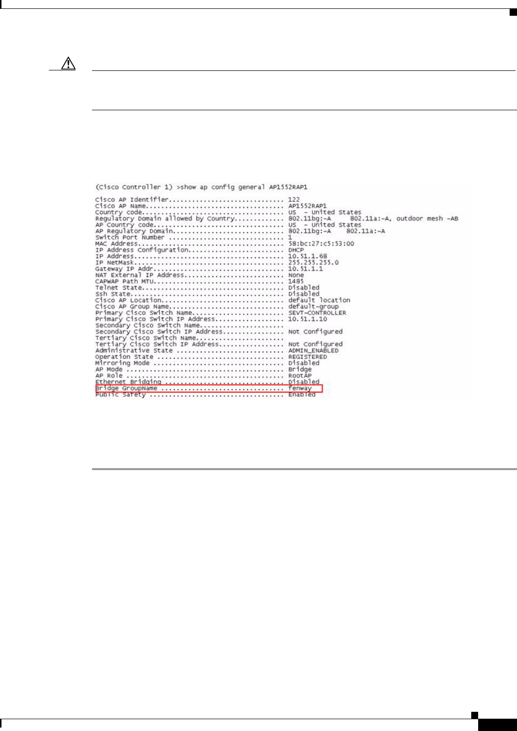
Step 2 To verify the BGN, enter the following command:
(Cisco controller) > show ap config general AP_Name
Information similar to the following is displayed.
Verifying BGN Using the GUI
To verify BGN using the GUI, follow these steps:
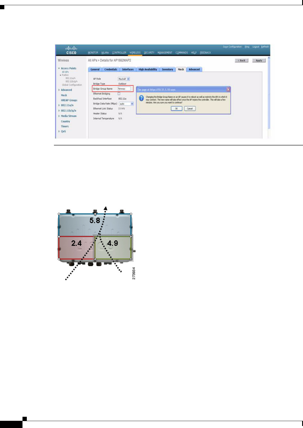
Step 1 Click Wireless > Access Points > AP Name. the details page for the selected mesh access point appears.
Step 2 Click the Mesh tab. Details for the mesh access point including the BGN appears. (See Figure 9-34.)
9-56
Cisco Wireless LAN Controller Configuration Guide
OL-21524-02
Chapter 9 Controlling Mesh Access Points
Adding Mesh Access Points to the Mesh Network
Figure 9-34 AP Name > Mesh
Configuring Public Safety Band Settings
A public safety band (4.9 GHz) is supported on the AP1522 and AP1524PS. (See Figure 9-35.)
Figure 9-35 AP 1524PS Diagram Showing Radio Placement
• For the AP1524PS, the 4.9-GHz radio is independent of the 5-GHz radio and is not used for
backhaul. The 5.8 GHz is used only for backhaul, and there is no client access possible on it. On the
AP1524PS, the 4.9-GHz band is enabled by default.
–
In Japan, 4.9 GHz is enabled by default as 4.9 GHz is unlicensed.
• For AP1522s, you can enable the 4.9-GHz public safety band on the backhaul. This step can only
be done at the global level and cannot be done on a per mesh access point basis.
–
For client access on the 4.9-GHz band on the AP1522, you have to enable the feature universal
client access.
• For public safety-only deployments, the AP1522 and the AP1524PS must each be connected to its
own separate RAP-based tree. For such deployments, the 1522 must use the 4.9-GHz backhaul and
the 1524PS must be in its own RAP tree and use the 5.8-GHz backhaul.
• In some parts of the world including the USA, you can only have public safety traffic on the 4.9-GHz
backhaul. Check the destination countries compliance before installing.
9-57
Cisco Wireless LAN Controller Configuration Guide
OL-21524-02
Chapter 9 Controlling Mesh Access Points
Adding Mesh Access Points to the Mesh Network
The 4.9-GHz subband radio on the AP1524PS supports public safety channels within the 5-MHz
(channels 1 to 10), 10-MHz (channels 11 to 19), and 20-MHz (channels 20 to 26) bandwidths.
• The following data rates are supported within the 5 MHz bandwidth: 1.5, 2.25, 3, 4.5, 6, 9, 12, and
13.5 Mbps. The default rate is 6 Mbps.
• The following data rates are supported within the 10-MHz bandwidth: 3, 4.5, 6, 9, 12, 18, 24, and
27 Mbps. The default rate is 12 Mbps.
Note • Those AP1522s with serial numbers prior to FTX1150XXXX do not support 5 and 10 MHz
channels on the 4.9-GHz radio; however, a 20-MHz channel is supported.
• Those AP1522s with serial numbers after FTX1150XXXX support 5, 10, and 20 MHz channels.
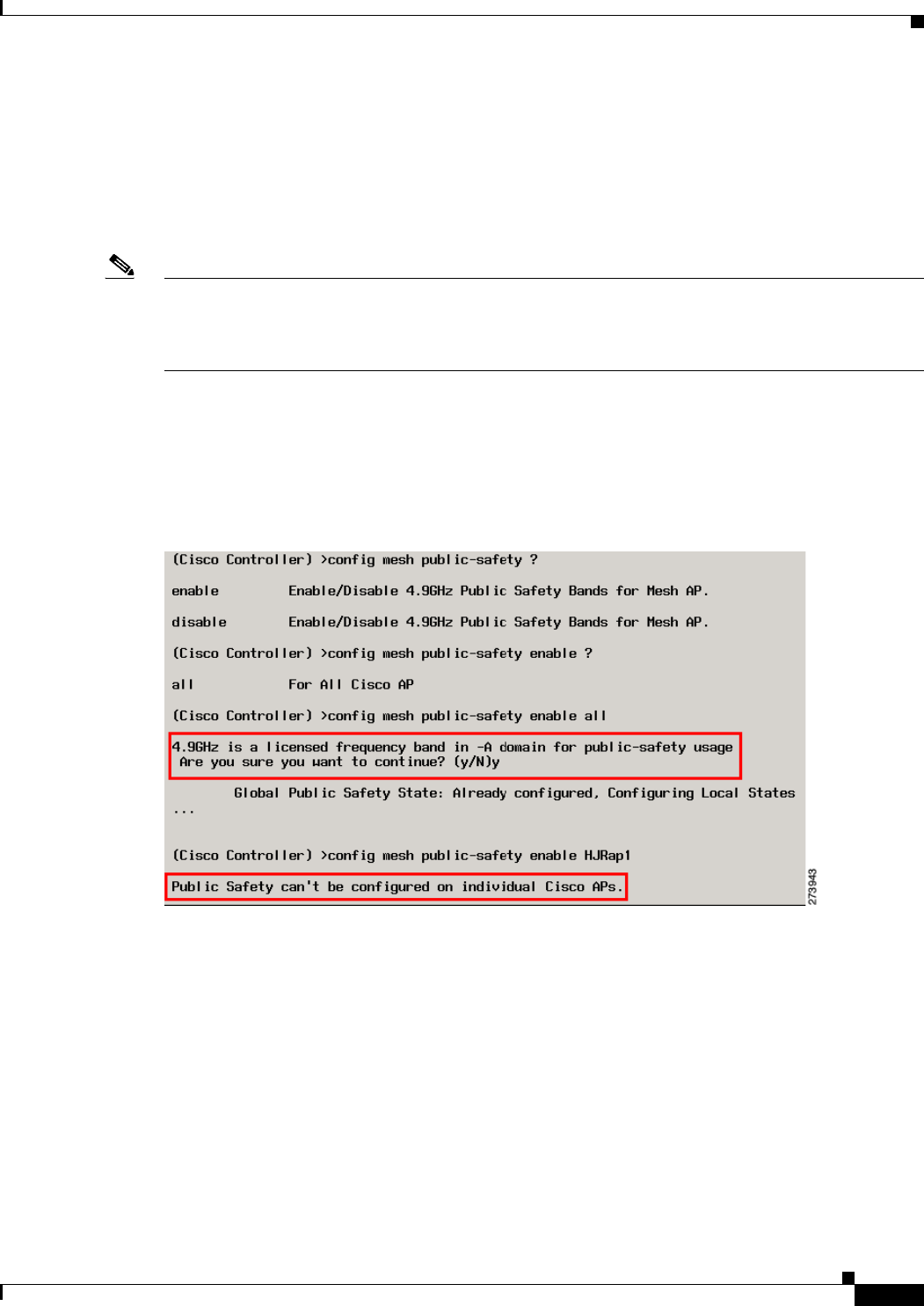
Enabling the 4.9-GHz Band
When you attempt to enable the 4.9-GHz band, you get a warning that the band is a licensed band in
most parts of the world. (See Figure 9-36.)
Figure 9-36 Public Safety Warning During Configuration
• To verify that a public safety band is on the mesh access point using the CLI, enter the following
command:
(Cisco controller) show mesh public-safety
Global Public Safety status: enabled
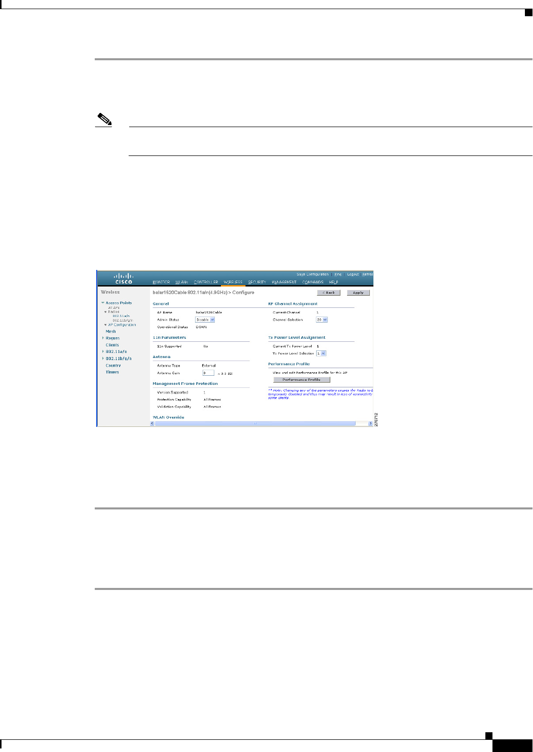
• To verify that a public safety band is on the mesh access point using the GUI:
Wireless > Access Points > 802.11a radio > Configure (from the Antenna drop-down list)
Configuring Interoperability with Cisco 3200
Cisco AP1522 and AP1524PS can interoperate with the Cisco 3200 on the public safety channel
(4.9-GHz) as well as the 2.4-GHz access and 5.8-GHz backhaul.

9-58
Cisco Wireless LAN Controller Configuration Guide
OL-21524-02
Chapter 9 Controlling Mesh Access Points
Adding Mesh Access Points to the Mesh Network
The Cisco 3200 creates an in-vehicle network in which devices such as PCs, surveillance cameras, digital
video recorders, printers, PDAs, and scanners can share wireless networks such as cellular or WLAN
based services back to the main infrastructure. This feature allows data collected from in-vehicle
deployments such as a police cars to be integrated into the overall wireless infrastructure.
This section provides configuration guidelines and step-by-step instructions for configuring
interoperability between the Cisco 3200 and the AP1522 and the AP1524PS.
For specific interoperability details between series 1130, 1240, and 1520 (1522, 1524PS) mesh access
points and Cisco 3200, see Table 9-8.
Enabling AP1522 to Associate with Cisco 3200 Using the GUI
To enable AP1522 to associate with Cisco 3200, follow these steps:
Ta b l e 9-8 Mesh Access Points and Cisco 3200 Interoperability
Mesh Access Point Model Cisco 3200 Model
1552, 15221
1. Universal access must be enabled on the AP1522 if connecting to a Cisco 3200 on the 802.11a radio or 4.9-GHz band.
c32012, c32023, c32054
2. Model c3201 is a Cisco 3200 with a 802.11b/g radio (2.4-GHz).
3. Model c3202 is a Cisco 3200 with a 4-9-GHz subband radio.
4. Model c3205 is a Cisco 3200 with a 802.11a radio (5.8-GHz subband).
Configuration Guidelines for Public Safety 4.9-GHz Band
For the AP1522 or AP1524PS and Cisco 3200 to interoperate on the public safety network, the
following configuration guidelines must be met:
Client access must be enabled on the backhaul (mesh global parameter). This feature is not
supported on the AP1524PS.
Public safety must be enabled globally on all mesh access points (MAPs) in the mesh network.
The channel number assignment on the AP1522 or AP1524PS must match those on the Cisco 3200
radio interfaces:
Channels 20 (4950 GHz) through 26 (4980 GHz) and subband channels 1 through 19 (5 and 10
MHz) are used for Cisco 3200 interoperability. This configuration change is made on the
controller. No changes are made to the mesh access point configuration.
Channel assignments are only made to the RAP. Updates to the MAP are propagated by the
RAP.
The default channel width for Cisco 3200s is 5 MHz. You must either change the channel width to 10
or 20 MHz to enable WGBs to associate with the AP1522 and AP1524PS or change the channel on the
AP1522 or AP1524PS to a channel in the 5-MHz band (channels 1 to 10) or 10-MHz band (channels
11 to 19).
Radio (802.11a) must be disabled when configuring channels and then reenabled when using the
CLI. When using the GUI, enabling and disabling of the 802.11a radio for channel configuration is
not required.
Cisco 3200s can scan channels within but not across the 5, 10 or 20-MHz bands.
1524PS c3201, c3202
1524SB, 1130, 1240, Indoor 802.11n mesh access
points
c3201, c3205
9-59
Cisco Wireless LAN Controller Configuration Guide
OL-21524-02
Chapter 9 Controlling Mesh Access Points
Adding Mesh Access Points to the Mesh Network
Step 1 To enable the backhaul for client access, choose Wireless > Mesh to access the Mesh page.
Step 2 Select the Backhaul Client Access Enabled check box to allow wireless client association over the 802.11a
radio. Click Apply.
Note You are prompted with a message to allow reboot of all the mesh access points to enable
Backhaul Client Access on a network. Click OK.
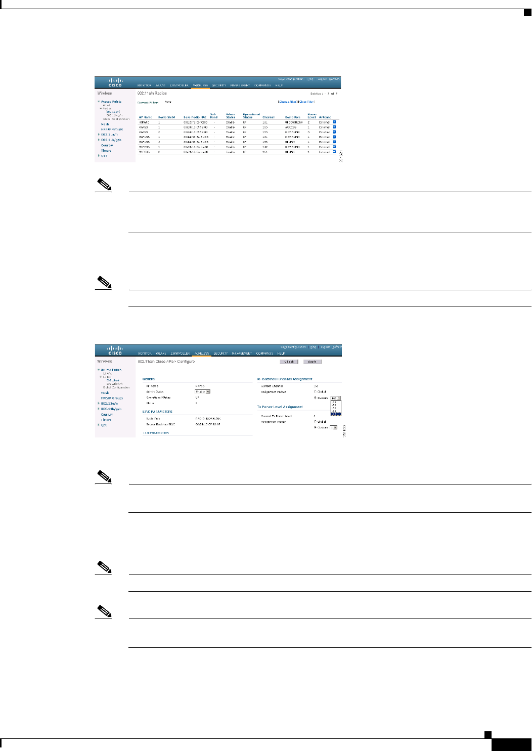
Step 3 To assign the channel to use for the backhaul (channels 20 through 26), click Wireless > Access Points
> Radio and select 802.11a/n from the Radio subheading. A summary page for all 802.11a radios
displays.
Step 4 At the Antenna drop-down list for the appropriate RAP, select Configure. The Configure page seen in
Figure 9-37 is displayed.
Figure 9-37 Wireless > Access Points > Radio > 802.11 a/n > Configure Page
Step 5 At the RF Backhaul Channel Assignment section, select the Custom option for the Assignment Method
option and select any channel between 1 and 26.
Step 6 Click Apply to commit your changes.
Step 7 Click Save Configuration to save your changes.
Enabling 1522 and 1524PS Association with Cisco 3200 Using the CLI
To enable an AP1522 or AP1524PS to associate with Cisco 3200, follow these steps:
Step 1 To enable client access mode on the AP1522, enter this command:
config mesh client-access enable
Step 2 To enable the public safety on a global basis, enter this command:
config mesh public-safety enable all
Step 3 To enable the public safety channels, enter these commands:
a. On the AP1522, enter these commands:

9-60
Cisco Wireless LAN Controller Configuration Guide
OL-21524-02
Chapter 9 Controlling Mesh Access Points
Adding Mesh Access Points to the Mesh Network
config 802.11a disable Cisco_MAP
config 802.11a channel ap Cisco_MAP channel number
config 802.11a enable Cisco_MAP
b. On the AP1524PS, enter these commands:
config 802.11–a49 disable Cisco_MAP
config 802.11–a49 channel ap Cisco_MAP channel number
config 802.11–a49 enable Cisco_MAP
Note Enter the config 802.11–a58 enable Cisco_MAP command to enable a 5.8-GHz radio.
Note For both the AP1522 and AP1524PS, channel number is equal to any value 1 to 26.
Step 4 To save your changes, enter this command:
save config
Step 5 To verify your configuration, enter these commands:
show mesh public-safety
show mesh client-access
show ap config 802.11a summary (1522 only)
show ap config 802.11–a49 summary (1524PS only)
Note Enter the show config 802.11-a58 summary command to display configuration details for a
5.8-GHz radio.
Configuring Power and Channel Settings
The backhaul channel (802.11a/n) can be configured on a RAP. MAPs tune to the RAP channel. The
local access can be configured independently for MAP.
Configuring Power and Channel Settings Using the GUI
To configure power and channel using the controller GUI, follow these steps:
Step 1 Choose Wireless > Access Points > 802.11a/n (see Figure 9-38).
9-61
Cisco Wireless LAN Controller Configuration Guide
OL-21524-02
Chapter 9 Controlling Mesh Access Points
Adding Mesh Access Points to the Mesh Network
Figure 9-38 Access Points > 802.11a/n Radios Page
Note In Figure 9-38, radio slots are displayed for each radio. For an AP1524SB, the 802.11a radio will
display for slots 1 and 2 that operate in the 5-GHz band. For an AP1524PS, the 802.11a radio
will display for slots 1 and 2, operating in the 5-GHz and 4.9-GHz bands respectively.
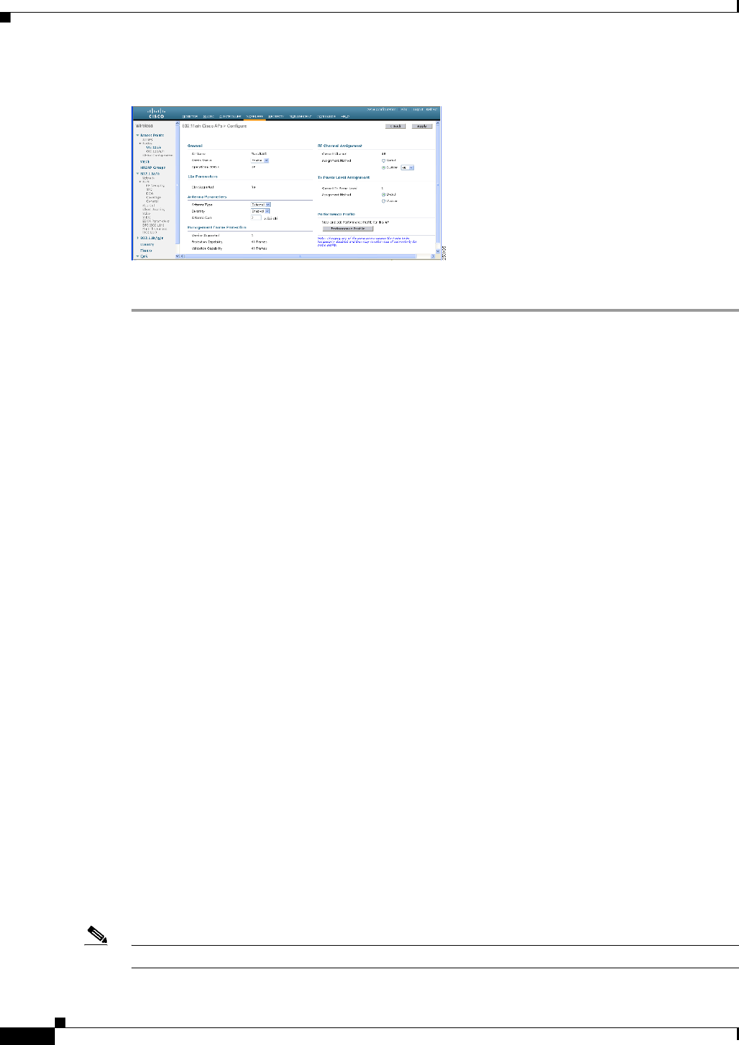
Step 2 Select configure from the Antenna drop-down list for the 802.11a/n radio. The Configure page is
displayed (see Figure 9-39).
Note For the 1524SB, select the Antenna drop-down list for a RAP with a radio role of downlink.
Figure 9-39 802.11a/n Cisco APs > Configure Page
Step 3 Assign a channel (assignment methods of global and custom) for the radio.
Note When you assign a channel to the AP1524SB, choose the Custom assignment method, and select
one of the supported channels for the 5-GHz band.
Step 4 Assign Tx power levels (global and custom) for the radio.
There are five selectable power levels for the 802.11a backhaul for AP1500s.
Note The default Tx power level on the backhaul is the highest power level (Level 1).
Note Radio Resource Management (RRM) is OFF (disabled) by default. RRM cannot be turned ON
(enabled) for the backhaul.
Step 5 Click Apply when power and channel assignment are complete.
Step 6 From the 802.11a/n Radios page, verify that channel assignments were made correctly (see Figure 9-40).

9-62
Cisco Wireless LAN Controller Configuration Guide
OL-21524-02
Chapter 9 Controlling Mesh Access Points
Adding Mesh Access Points to the Mesh Network
Figure 9-40 Channel Assignment
Configuring the Channels on the Serial Backhaul Using the CLI
To configure channels on the serial backhaul of the RAP using the controller CLI, follow these steps:
Step 1 To configure the backhaul channel on the radio in slot 2 of the RAP, enter this command:
config slot 2 channel ap Cisco_RAPSB channel
The available channels for the 5.8-GHz band are 149, 153, 157, 161, and 165.
Step 2 To configure the transmit power level on the radio in slot 2 of the RAP, enter this command:
config slot 2 txPower ap Cisco_RAPSB power
Valid values are 1 through 5; the default value is 1.
Step 3 To display the configurations on the mesh access points, enter these commands:
• show mesh path MAP
Information similar to the following appears:
RAPSB is a Root AP.
• show mesh backhaul RAPSB
Information similar to the following appears:
Current Backhaul Slot(s)......................... 1, 2,
Basic Attributes for Slot 1
Radio Type................................... RADIO_TYPE_80211a
Radio Role................................... ACCESS
Administrative State ........................ ADMIN_ENABLED
Operation State ............................. UP
Current Tx Power Level ...................... 1
Current Channel ............................. 165
Antenna Type................................. EXTERNAL_ANTENNA
External Antenna Gain (in .5 dBm units)...... 0
Basic Attributes for Slot 2
Radio Type................................... RADIO_TYPE_80211a
Radio Role................................... RADIO_DOWNLINK
Administrative State ........................ ADMIN_ENABLED
Operation State ............................. UP
AP Name/Radio Channel Rate Link-Snr Flags State
MAP1SB 161 auto 60 0x10ea9d54 UPDATED NEIGH PARENT BEACON
RAPSB 153 auto 51 0x10ea9d54 UPDATED NEIGH PARENT BEACON

9-63
Cisco Wireless LAN Controller Configuration Guide
OL-21524-02
Chapter 9 Controlling Mesh Access Points
Adding Mesh Access Points to the Mesh Network
Current Tx Power Level ...................... 3
Current Channel ............................. 153
Antenna Type................................. EXTERNAL_ANTENNA
External Antenna Gain (in .5 dBm units)...... 0
• show ap channel MAP1SB
Information similar to the following appears:
802.11b/g Current Channel ................. 11
Slot Id ................................... 0
Allowed Channel List....................... 1,2,3,4,5,6,7,8,9,10,11
802.11a(5.8Ghz) Current Channel ........... 161
Slot Id ................................... 1
Allowed Channel List....................... 149,153,157,161,165
802.11a(5.8Ghz) Current Channel ........... 153
Slot Id ................................... 2
Allowed Channel List....................... 149,153,157,161,165
Configuring Antenna Gain
You must configure the antenna gain for the mesh access point to match that of the antenna installed
using the controller GUI or controller CLI.
Configuring Antenna Gain Using the GUI
To configure antenna parameters using the controller GUI, follow these steps:
Step 1 Choose Wireless > Access Points > Radio > 802.11a/n to open the 802.11a/n Radios page.
Step 2 For the mesh access point antenna you want to configure, hover the mouse over the blue arrow (far right)
to display antenna options. Choose Configure. (See Figure 9-41.)
Note Only external antennas have configurable gain settings.
Figure 9-41 802.11a/n Radios Page
Step 3 In the Antenna Parameters section, enter the antenna gain.
The gain is entered in 0.5 dBm units. For example, 2.5 dBm = 5. (See Figure 9-42.)
Note The entered gain value must match that value specified by the vendor for that antenna.
9-64
Cisco Wireless LAN Controller Configuration Guide
OL-21524-02
Chapter 9 Controlling Mesh Access Points
Adding Mesh Access Points to the Mesh Network
Figure 9-42 802.11 a/n Cisco APs > Configure Page
Step 4 Click Apply and Save Configuration to save the changes.
Configuring Antenna Gain Using the CLI
Enter this command to configure the antenna gain for the 802.11a backhaul radio using the controller
CLI:
config 802.11a antenna extAntGain antenna_gain AP_name
where gain is entered in 0.5-dBm units (for example, 2.5 dBm =5).
Backhaul Channel Deselection on Serial Backhaul Access Point
This feature is applicable to mesh APs with two 5-GHz radios, such as 1524SB (serial backhaul).
The backhaul channel deselection feature helps you to restrict the set of channels available to be assigned
for the serial backhaul MAPs and RAPs. Because 1524SB MAP channels are automatically assigned,
this feature helps in regulating the set of channels that get assigned to mesh access points. For example,
if you do not want channel 165 to get assigned to any of the 1524SB mesh access points, you need to
remove channel 165 from the DCA list and enable this feature.
When you remove certain channels from the DCA list and enable the mesh backhaul dca-channel
command, those channels will not be assigned to any serial backhaul access points in any scenario. Even
if a radar is detected on all channels within the DCA list channels, the radio will be shut down rather
than moved to channels outside it. A trap message is sent to the WCS, and the message is displayed
showing that the radio has been shut down because of DFS. You will not be able to assign channels to
the serial backhaul RAP outside of the DCA list with the config mesh backhaul dca-channels enable
command enabled. However, this is not case for the APs with one 5-GHz radio such as 1552, 1522, and
1524PS APs. For these APs, you can assign any channel outside of the DCA list for a RAP, and the
controller/AP can also select a channel outside of the DCA list if no radar-free channel is available from
the list.
This feature is best suited in an interoperability scenario with indoor mesh access points or workgroup
bridges that support a channel set that is different from outdoor access points. For example, channel 165
is supported by outdoor access points but not by indoor access points in the -A domain. By enabling the
backhaul channel deselection feature, you can restrict the channel assignment to only those channels that
are common to both indoor and outdoor access points.
Note Channel deselection is applicable to 7.0 and later releases.

9-65
Cisco Wireless LAN Controller Configuration Guide
OL-21524-02
Chapter 9 Controlling Mesh Access Points
Adding Mesh Access Points to the Mesh Network
In some scenarios, there may be two linear tracks or roads for mobility side by side. Because channel
selection of MAPs happens automatically, there can be a hop at a channel, which is not available on the
autonomous side, or the channel has to be skipped when the same or adjacent channel is selected in a
neighborhood access point that belongs to a different linear chain.
Configuring Backhaul Channel Deselection Using the GUI
To configure the backhaul channel deselection, follow these steps:
Step 1 Choose Controller > Wireless > 802.11a/n > RRM > DCA
The Dynamic Channel Assignment Algorithm page appears.
Step 2 Select one or more channels to include in the DCA list.
The channels included in the DCA list will not be assigned to the access points associated to this
controller during automatic channel assignment.
Step 3 Choose Wireless > Mesh
The Mesh page appears.
Step 4 Select the Mesh DCA Channels check box to enable the backhaul channel deselection using the DCA
list. This option is applicable for serial backhaul access points.
Step 5 After you enable the backhaul deselection option, choose Wireless > Access Points > Radios >
802.11a/n to configure the channel for the RAP downlink radio.
Step 6 From the list of access points, click on the Antenna drop-down list for a RAP and choose Configure.
The Configure page appears.
Step 7 In the RF Backhaul Channel assignment section, choose Custom.
Step 8 Select a channel for the RAP downlink radio from the drop-down list, which appears when you choose
Custom.
Step 9 Click Apply to apply and save the backhaul channel deselection configuration changes.
Configuring Backhaul Channel Deselection Using the CLI
To configure backhaul channel deselection using CLI, follow these steps:
Step 1 From the controller prompt, enter the show advanced 802.11a channel command to review the channel
list already configured in the DCA list.
(Controller) > show advanced 802.11a channel
Automatic Channel Assignment
Channel Assignment Mode........................ AUTO
Channel Update Interval........................ 600 seconds
Anchor time (Hour of the day).................. 0
Channel Update Contribution.................... SNI..
CleanAir Event-driven RRM option............... Enabled
CleanAir Event-driven RRM sensitivity.......... Medium
Channel Assignment Leader...................... 09:2b:16:28:00:03
Last Run....................................... 286 seconds ago
DCA Sensitivity Level.......................... MEDIUM (15 dB)
DCA 802.11n Channel Width...................... 20 MHz
DCA Minimum Energy Limit....................... -95 dBm

9-66
Cisco Wireless LAN Controller Configuration Guide
OL-21524-02
Chapter 9 Controlling Mesh Access Points
Adding Mesh Access Points to the Mesh Network
Channel Energy Levels
Minimum...................................... unknown
Average...................................... unknown
Maximum...................................... unknown
Channel Dwell Times
Minimum...................................... 0 days, 17 h 02 m 05 s
Average...................................... 0 days, 17 h 46 m 07 s
Maximum...................................... 0 days, 18 h 28 m 58 s
802.11a 5 GHz Auto-RF Channel List
--More-- or (q)uit
Allowed Channel List......................... 36,40,44,48,52,56,60,64,116,
140
Unused Channel List.......................... 100,104,108,112,120,124,128,
132,136
DCA Outdoor AP option.......................... Disabled
Step 2 To add a channel to the DCA list, enter the config advanced 802.11a channel add channel number
command, where channel number is the channel number that you want to add to the DCA list.
You can also delete a channel from the DCA list by entering the config advanced 802.11a channel
delete channel number command, where channel number is the channel number that you want to delete
from the DCA list.
Before you add or delete a channel to or from the DCA list, ensure that the 802.11a network is disabled.
• To disable the 802.11a network, enter the following command:
config 802.11a disable network
• To enable the 802.11a network, enter the following command:
config 802.11a enable network
You cannot directly delete a channel from the DCA list if it is assigned to any 1524 RAP. To delete a
channel assigned to a RAP, you must first change the channel assigned to the RAP and then enter the
config advanced 802.11a channel delete channel number command from the controller.
The following is a sample output of the add channel and delete channel commands:
(Controller) > config 802.11a disable network
Disabling the 802.11a network may strand mesh APs. Are you sure you want to continue?
(y/n)y
(Controller) > config advanced 802.11a channel add 132
(Controller) > config advanced 802.11a channel delete 116
802.11a 5 GHz Auto-RF:
Allowed Channel List......................... 36,40,44,48,52,56,60,64,116,
132,140
DCA channels for cSerial Backhaul Mesh APs is enabled.
DCA list should have at least 3 non public safety channels supported by Serial Backhaul
Mesh APs.
Otherwise, the Serial Backhaul Mesh APs can get stranded.
Are you sure you want to continue? (y/N)y
Failed to delete channel.
Reason: Channel 116 is configured for one of the Serial Backhaul RAPs.
Disable mesh backhaul dca-channels or configure a different channel for Serial Backhaul
RAPs.

9-67
Cisco Wireless LAN Controller Configuration Guide
OL-21524-02
Chapter 9 Controlling Mesh Access Points
Adding Mesh Access Points to the Mesh Network
(Controller) > config advanced 802.11a channel delete 132
802.11a 5 GHz Auto-RF:
Allowed Channel List..................... 36,40,44,48,52,56,60,64,116,132,140
DCA channels for Serial Backhaul Mesh APs is enabled.
DCA list should have at least 3 non public safety channels supported by Serial Backhaul
Mesh APs.
Otherwise, the Serial Backhaul Mesh APs can get stranded.
Are you sure you want to continue? (y/N)y
(Controller) > config 802.11a enable network
Step 3 After a suitable DCA list has been created, enter the config mesh backhaul dca-channels enable
command to enable the backhaul channel deselection feature for mesh access points.
You can enter the config mesh backhaul dca-channels disable command if you want to disable the
backhaul channel deselection feature for mesh access points.
It is not required that you disable 802.11a network to enable or disable this feature.
The following is a sample output:
(Controller) > config mesh backhaul dca-channels enable
802.11a 5 GHz Auto-RF:
Allowed Channel List......................... 36,40,44,48,52,56,60,64,116,
140
Enabling DCA channels for c1524 mesh APs will limit the channel set to the DCA channel
list.
DCA list should have at least 3 non public safety channels supported by Serial Backhaul
Mesh APs.
Otherwise, the Serial Backhaul Mesh APs can get stranded.
Are you sure you want to continue? (y/N)y
(Controller) > config mesh backhaul dca-channels disable
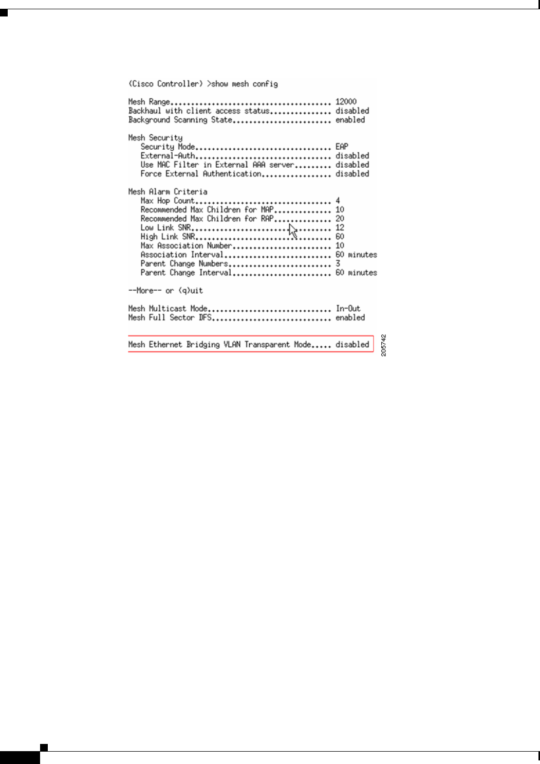
Step 4 To check the current status of the backhaul channel deselection feature, enter the show mesh config
command.
The following is a sample output:
(Controller) > show mesh config
Mesh Range....................................... 12000
Mesh Statistics update period.................... 3 minutes
Backhaul with client access status............... enabled
Background Scanning State........................ enabled
Backhaul Amsdu State............................. disabled
Mesh Security
Security Mode................................. PSK
External-Auth................................. enabled
Radius Server 1............................ 209.165.200.240
Use MAC Filter in External AAA server......... disabled
Force External Authentication................. disabled
Mesh Alarm Criteria
Max Hop Count................................. 4
Recommended Max Children for MAP.............. 10
Recommended Max Children for RAP.............. 20
Low Link SNR.................................. 12
High Link SNR................................. 60
Max Association Number........................ 10

9-68
Cisco Wireless LAN Controller Configuration Guide
OL-21524-02
Chapter 9 Controlling Mesh Access Points
Adding Mesh Access Points to the Mesh Network
Association Interval.......................... 60 minutes
Parent Change Numbers......................... 3
--More-- or (q)uit
Parent Change Interval........................ 60 minutes
Mesh Multicast Mode.............................. In-Out
Mesh Full Sector DFS............................. enabled
Mesh Ethernet Bridging VLAN Transparent Mode..... enabled
Mesh DCA channels for Serial Backhaul APs................ disabled
Step 5 Enter the config slot slot number channel ap ap-name channel number command to assign a particular
channel to the 1524 RAP downlink radio.
• slot number refers to the slot of the downlink radio to which the channel is assigned.
• ap-name refers to the name of the access point on which the channel is configured.
• channel number refers to the channel that is assigned to a slot on the access point.
Slot 2 of the 1524 RAP acts as a downlink radio. If backhaul channel deselection is enabled, you can
assign only those channels that are available in the DCA list the access point.
The following is a sample output:
(Controller) > config slot 2 channel ap Controller-RAP2-1524 136
Mesh backhaul dca-channels is enabled. Choose a channel from the DCA list.
(Controller) > config slot 2 channel ap Controller-RAP2-1524 140
Backhaul Channel Deselection Guidelines
Follow these guidelines when configuring backhaul channel deselection:
• Channels for serial backhaul RAP 11a access radio and both 11a radios of serial backhaul MAPs are
assigned automatically. You cannot configure these channels.
• Look out for trap logs on the controller. In case of radar detection and subsequent channel change,
messages similar to below appear:
Channel changed for Base Radio MAC: 00:1e:bd:19:7b:00 on 802.11a
radio. Old channel: 132. New Channel: 116. Why: Radar. Energy
before/after change: 0/0. Noise before/after change: 0/0.
Interference before/after change: 0/0.
Radar signals have been detected on channel 132 by 802.11a radio
with MAC: 00:1e:bd:19:7b:00 and slot 2
• For every serial backhaul AP, channels on downlink and uplink radios should always be
noninterfering (for example, if the uplink is channel 104, the 100, 104, and 108 channels cannot be
assigned for a downlink radio on that AP). An alternate adjacent channel is also selected for an 11a
access radio on RAP.
• If radar signals are detected on all channels except the uplink radio channel, the downlink radio will
be shut down and the uplink radio will act as both an uplink and a downlink (that is, the behavior is
similar to 1522 APs in this case).

9-69
Cisco Wireless LAN Controller Configuration Guide
OL-21524-02
Chapter 9 Controlling Mesh Access Points
Adding Mesh Access Points to the Mesh Network
• Radar detection is cleared after 30 minutes. Any radio that is shut down because of radar detection
should be back up and operational after this duration.
• There is a 60-second silent period immediately after moving to a DFS-enabled channel (irrespective
of whether the channel change is because of radar detection or user configured in case of a RAP)
during which the AP scans for radar signals without transmitting anything. A small period (60
seconds) of downtime may occur because of radar detection, if the new channel is also DFS-enabled.
If radar detection occurs again on the new channel during the silent period, the parent changes its
channel without informing the child AP because it is not allowed to transmit during the silent period.
In this case, the child AP dissociates and goes back to scan mode, rediscovers the parent on the new
channel and then joins back, which causes a slightly longer (approximately 3 minutes) downtime.
• For a RAP, the channel for the downlink radio is always selected from within the DCA list,
irrespective of whether the backhaul channel deselection feature is enabled or not. The behavior is
different for a MAP because the MAP can pick any channel that is allowed for that domain, unless
the backhaul channel deselection feature is enabled. We recommend that you have quite a few
channels added to the 802.11a DCA channel list to prevent any radios getting shut down because of
a lack of channels even if the backhaul channel deselection feature is not in use.
• Because the DCA list that was used for the RRM feature is also used for mesh APs through the
backhaul channel deselection feature, keep in mind that any addition or deletion of channels from
the DCA list will affect the channel list input to the RRM feature for nonmesh access points as well.
RRM is off for mesh.
• For -M domain APs, a slightly longer time interval (25 to 50 percent more time than usual) may be
required for the mesh network to come up because there is a longer list of DFS-enabled channels in
the -M domain, which each AP scans before joining the parent.
Configuring Dynamic Channel Assignment
Using the controller GUI, follow these steps to specify the channels that the dynamic channel assignment
(DCA) algorithm considers when selecting the channels to be used for RRM scanning. This functionality
is helpful when you know that the clients do not support certain channels because they are legacy devices
or they have certain regulatory restrictions.
The steps outlined in this section are only relevant to mesh networks.
Step 1 To disable the 802.11a/n or 802.11b/g/n network, follow these steps:
a. Choose Wireless > 802.11a/n or 802.11b/g/n > Network to open the 802.11a (or 802.11b/g) Global
Parameters page.
b. Deselect the 802.11a (or 802.11b/g) Network Status check box.
c. Click Apply to commit your changes.
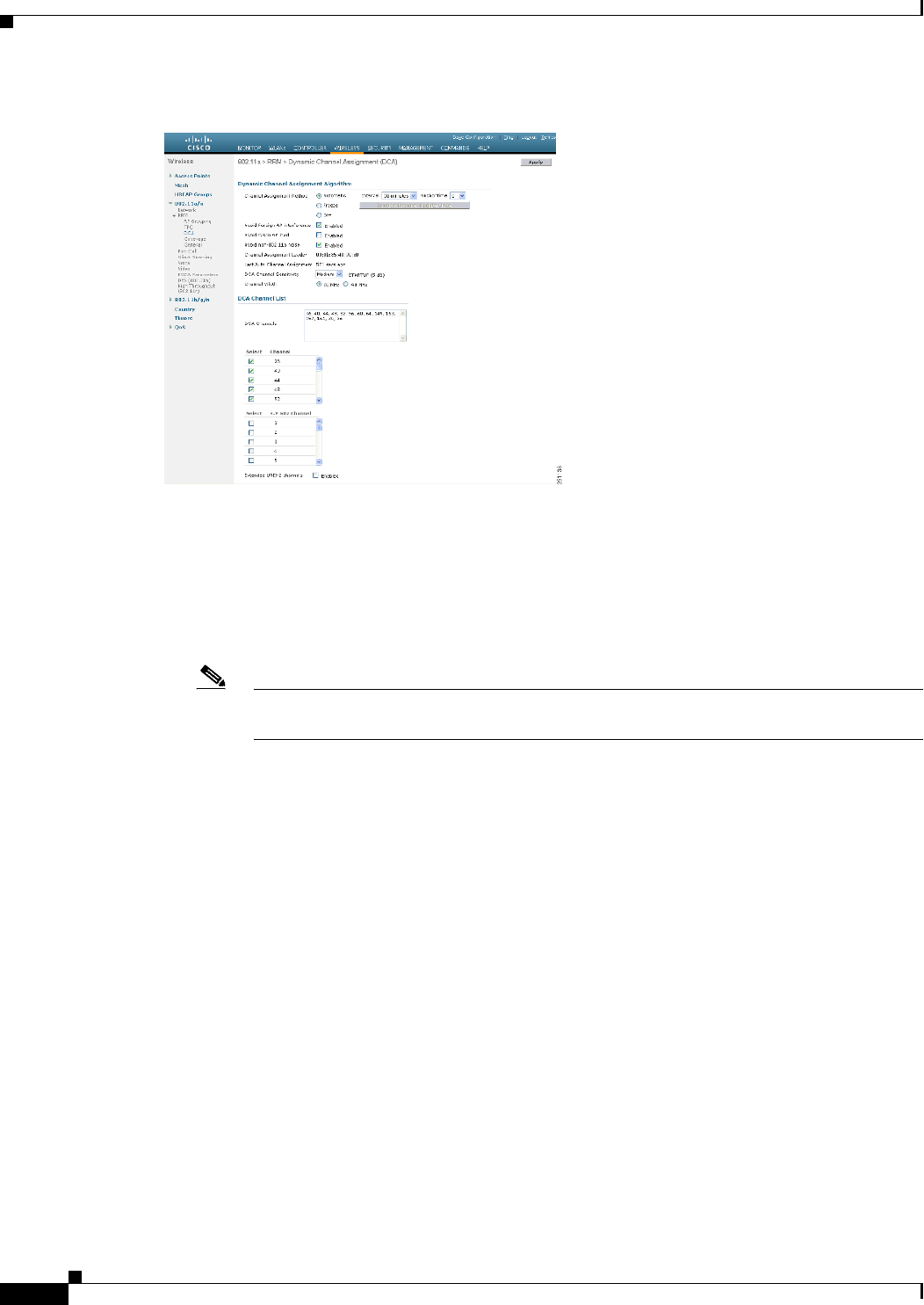
Step 2 Choose Wireless > 802.11a/n or 802.11b/g/n > RRM > DCA to open the 802.11a (or 802.11b/g) > RRM
> Dynamic Channel Assignment (DCA) page. (See Figure 9-43.)
9-70
Cisco Wireless LAN Controller Configuration Guide
OL-21524-02
Chapter 9 Controlling Mesh Access Points
Adding Mesh Access Points to the Mesh Network
Figure 9-43 802.11a > RRM > Dynamic Channel Assignment (DCA) Page
Step 3 Choose one of the following options from the Channel Assignment Method drop-down list to specify the
controller’s DCA mode:
• Automatic—Causes the controller to periodically evaluate and, if necessary, update the channel
assignment for all joined mesh access points. This is the default value.
• Freeze—Causes the controller to evaluate and update the channel assignment for all joined mesh
access points, if necessary, but only when you click Invoke Channel Update Once.
Note The controller does not evaluate and update the channel assignment immediately after you
click Invoke Channel Update Once. It waits for the next interval to elapse.
• OFF—Turns off DCA and sets all mesh access point radios to the first channel of the band, which
is the default value. If you choose this option, you must manually assign channels on all radios.
Step 4 From the Interval drop-down list, choose one of the following options to specify how often the DCA
algorithm is allowed to run: 10 minutes, 1 hour, 2 hours, 3 hours, 4 hours, 6 hours, 8 hours, 12 hours, or
24 hours. The default value is 10 minutes.
Step 5 From the AnchorTime drop-down list, choose a number to specify the time of day when the DCA
algorithm is to start. The options are numbers between 0 and 23 (inclusive) representing the hour of the
day from 12:00 a.m. to 11:00 p.m.
Step 6 Select the Avoid Foreign AP Interference check box to cause the controller’s RRM algorithms to
consider 802.11 traffic from foreign access points (those access points not included in your wireless
network) when assigning channels to lightweight access points, or deselect it to disable this feature. For
example, RRM may adjust the channel assignment to have access points avoid channels close to foreign
access points. The default value is checked.
Step 7 Select the Avoid Cisco AP Load check box to cause the controller’s RRM algorithms to consider 802.11
traffic from Cisco lightweight access points in your wireless network when assigning channels, or
deselect it to disable this feature. For example, RRM can assign better reuse patterns to access points
that carry a heavier traffic load. The default value is deselected.

9-71
Cisco Wireless LAN Controller Configuration Guide
OL-21524-02
Chapter 9 Controlling Mesh Access Points
Adding Mesh Access Points to the Mesh Network
Step 8 Select the Avoid Non-802.11a (802.11b) Noise check box to cause the controller’s RRM algorithms to
consider noise (non-802.11 traffic) in the channel when assigning channels to lightweight access points,
or deselect it to disable this feature. For example, RRM may have access points avoid channels with
significant interference from nonaccess point sources, such as microwave ovens. The default value is
checked.
Step 9 From the DCA Channel Sensitivity drop-down list, choose one of the following options to specify how
sensitive the DCA algorithm is to environmental changes such as signal, load, noise, and interference
when determining whether to change channels:
• Low—The DCA algorithm is not particularly sensitive to environmental changes.
• Medium—The DCA algorithm is moderately sensitive to environmental changes.
• High—The DCA algorithm is highly sensitive to environmental changes.
The default value is Medium. The DCA sensitivity thresholds vary by radio band, as noted in Table 9-9.
Step 10 For 802.11a/n networks only, choose one of the following Channel Width options to specify the channel
bandwidth supported for all 802.11n radios in the 5-GHz band:
• 20 MHz—The 20-MHz channel bandwidth (default)
Note To override the globally configured DCA channel width setting, you can statically configure
an access point’s radio for 20-MHz mode on the 802.11a/n Cisco APs > Configure page. If
you ever change the static RF channel assignment method to Global on the access point
radio, the global DCA configuration overrides the channel width configuration that the
access point was previously using.
This page also shows the following nonconfigurable channel parameter settings:
• Channel Assignment Leader—The MAC address of the RF group leader, which is responsible for
channel assignment.
• Last Auto Channel Assignment—The last time RRM evaluated the current channel assignments.
Step 11 In the DCA Channel List section, the DCA Channels field shows the channels that are currently selected.
To choose a channel, select its check box in the Select column. To exclude a channel, deselect its check
box.
Range:
802.11a—36, 40, 44, 48, 52, 56, 60, 64, 100, 104, 108, 112, 116, 132, 136, 140, 149, 153, 157, 161, 165,
190, 196
802.11b/g—1, 2, 3, 4, 5, 6, 7, 8, 9, 10, 11
Default:
802.11a—36, 40, 44, 48, 52, 56, 60, 64, 100, 104, 108, 112, 116, 132, 136, 140, 149, 153, 157, 161
802.11b/g—1, 6, 11
Ta b l e 9-9 DCA Sensitivity Thresholds
Option 2.4-GHz DCA Sensitivity Threshold 5-GHz DCA Sensitivity Threshold
High 5 dB 5 dB
Medium 15 dB 20 dB
Low 30 dB 35 dB

9-72
Cisco Wireless LAN Controller Configuration Guide
OL-21524-02
Chapter 9 Controlling Mesh Access Points
Configuring Advanced Features
Note These extended UNII-2 channels in the 802.11a band do not appear in the channel list: 100, 104,
108, 112, 116, 132, 136, and 140. If you have Cisco Aironet 1500 series mesh access points in
the -E regulatory domain, you must include these channels in the DCA channel list before you
start operation. If you are upgrading from a previous release, verify that these channels are
included in the DCA channel list. To include these channels in the channel list, select the
Extended UNII-2 Channels check box.
Step 12 If you are using AP1500s in your network, you must set the 4.9-GHz channels in the 802.11a band on
which they are to operate. The 4.9-GHz band is for public safety client access traffic only. To choose a
4.9-GHz channel, select its check box in the Select column. To exclude a channel, deselect its check box.
Range:
802.11a—1, 2, 3, 4, 5, 6, 7, 8, 9, 10, 11, 12, 13, 14, 15, 16, 17, 18, 19, 20, 21, 22, 23, 24, 25, 26
Default:
802.11a—20, 26
Step 13 Click Apply to commit your changes.
Step 14 To reenable the 802.11a or 802.11b/g network, follow these steps:
a. Click Wireless > 802.11a/n or 802.11b/g/n > Network to open the 802.11a (or 802.11b/g) Global
Parameters page.
b. Select the 802.11a (or 802.11b/g) Network Status check box.
c. Click Apply to commit your changes.
Step 15 Click Save Configuration to save your changes.
To see why the DCA algorithm changed channels, click Monitor and then View All under Most Recent
Traps. The trap provides the MAC address of the radio that changed channels, the previous channel and
the new channel, the reason why the change occurred, the energy before and after the change, the noise
before and after the change, and the interference before and after the change.
Configuring Advanced Features
This section includes the following topics:
• Using the 2.4-GHz Radio for Backhaul, page 9-72
• Configuring Ethernet VLAN Tagging, page 9-74
• Workgroup Bridge Interoperability with Mesh Infrastructure, page 9-82
• Client Roaming, page 9-92
• Configuring Voice Parameters in Indoor Mesh Networks, page 9-94
• Enabling Mesh Multicast Containment for Video, page 9-104
Using the 2.4-GHz Radio for Backhaul
Until the 7.0 release, mesh used the 5-GHz radio for backhaul, and the 2.4-GHz radio was used only for
client access. The reasons for using only the 5-GHz radio for backhaul are as follows:

9-73
Cisco Wireless LAN Controller Configuration Guide
OL-21524-02
Chapter 9 Controlling Mesh Access Points
Configuring Advanced Features
• More channels are available
• More EIRP is available
• Less interference occurs
• Most of the client access occurs over the 2.4-GHz band
However, under certain conditions, such as dense foliage areas, you might have needed to use the
2.4-GHz band for a backhaul because it has better penetration.
With the 7.0.116.0 release, you can configure an entire mesh network to use a single backhaul that can
be either 5 GHz or 2.4 GHz.
Caution This feature is available only for AP1522 (two radios). This feature should be used only after exploring
the 5-GHz backhaul option.
Caution We recommend that you use 5 GHz as the first option and use 2.4 GHz only if the 5-GHz option does
not work.
Changing the Backhaul from 5 GHz to 2.4 GHz
When you specify only the RAP name as an argument to the command, the whole mesh sector changes
to 2.4 GHz or 5 GHz backhaul. The warning messages indicate the change in backhaul, whether it is
from 2.4 GHz to 5 GHz or vice versa.
Note The 2.4-GHz backhaul cannot be configured using the controller user interface, but only through the
CLI.
To change the backhaul from 5 GHz to 2.4 GHz, follow these steps:
Step 1 To change the backhaul, enter the following command:
(Cisco Controller) > config mesh backhaul slot 0 enable RAP
The following message appears;
Warning! Changing backhaul slot will bring down the mesh for renegotiation!!!
After backhaul is changed, 5 GHz client access channels need to be changed manually
Are you sure you want to continue? (y/N)
Step 2 Press y.
Note When you change the 5-GHz backhaul to local client access, the 5-GHz client access frequencies on all
the APs are the same, because the backhaul frequency is ported on these 5-GHz radios for client access.
You need to configure these channels for a better frequency planning.

9-74
Cisco Wireless LAN Controller Configuration Guide
OL-21524-02
Chapter 9 Controlling Mesh Access Points
Configuring Advanced Features
Changing the Backhaul from 2.4 GHz to 5 GHz
To change the backhaul from 2.4 GHz to 5 GHz, follow these steps:
Step 1 To change the backhaul, enter the following command:
(Cisco Controller) > config mesh backhaul slot 1 enable RAP
The following message appears:
Warning! Changing backhaul slot will bring down the mesh for renegotiation!!!
Are you sure you want to continue? (y/N)
Step 2 Press y.
Note You cannot configure the 2.4-GHz backhaul using the controller GUI, but you can configure the 2.4-GHz
backhaul using the CLI.
Verifying the Current Backhaul in Use
To verify the current backhaul in use, enter the following command:
(Cisco Controller) > show mesh backhaul AP_name
Note For a 5-GHz backhaul, dynamic frequency selection (DFS) occurs only on 5 GHz and not on 2.4 GHz.
The mechanism, which differs for RAP and MAP, is called a coordinated change mechanism.
When 5 GHz is converted to client access from the backhaul or 2.4 GHz is being used as backhaul, DFS
works similar to how it works for a local mode AP. DFS is detected on a 5-GHz client access, and the
request is sent to the controller for a new channel. Mesh adjacency is not affected for the 2.4-GHz
backhaul.
Note Universal client access is available on the 2.4-GHz backhaul.
Configuring Ethernet VLAN Tagging
Ethernet VLAN tagging allows specific application traffic to be segmented within a wireless mesh
network and then forwarded (bridged) to a wired LAN (access mode) or bridged to another wireless
mesh network (trunk mode).
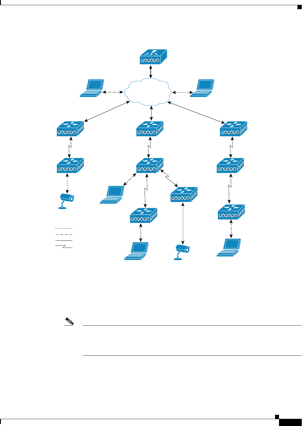
A typical public safety access application that uses Ethernet VLAN tagging is the placement of video
surveillance cameras at various outdoor locations within a city. Each of these video cameras has a wired
connection to a MAP. The video of all these cameras is then streamed across the wireless backhaul to a
central command station on a wired network (see Figure 9-44).
9-75
Cisco Wireless LAN Controller Configuration Guide
OL-21524-02
Chapter 9 Controlling Mesh Access Points
Configuring Advanced Features
Figure 9-44 Ethernet VLAN Tagging
Ethernet Port Notes
Ethernet VLAN tagging allows Ethernet ports to be configured as normal, access, or trunk in both indoor
and outdoor implementations:
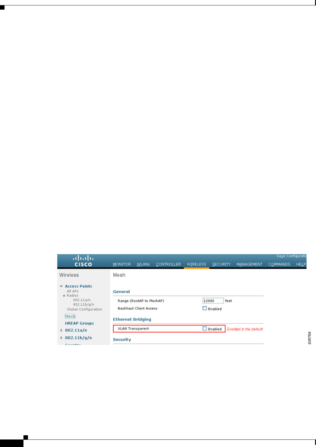
Note When VLAN Transparent is disabled, the default Ethernet port mode is normal. VLAN
Transparent must be disabled for VLAN tagging to operate and to allow configuration of
Ethernet ports. To disable VLAN Transparent, which is a global parameter, see the
“Configuring Global Mesh Parameters” section on page 9-35.
• Normal mode—In this mode, the Ethernet port does not accept or send any tagged packets. Tagged
frames from clients are dropped.
Use the normal mode in applications when only a single VLAN is in use or there is no need to
segment traffic in the network across multiple VLANs.
Mesh AP
Controller
VLAN R
VLAN G
Wired trunk links
11a bridge trunk links
Ethernet
client
Ethernet
client
Camera
Camera
Ethernet
client
Root AP Root AP
Root AP
Mesh AP Mesh AP
Mesh AP
Mesh AP
Mesh AP
251053
9-76
Cisco Wireless LAN Controller Configuration Guide
OL-21524-02
Chapter 9 Controlling Mesh Access Points
Configuring Advanced Features
• Access Mode—In this mode, only untagged packets are accepted. All incoming packets are tagged
with user-configured VLANs called access-VLANs.
Use the access mode for applications in which information is collected from devices connected to
the MAP, such as cameras or PCs, and then forwarded to the RAP. The RAP then applies tags and
forwards traffic to a switch on the wired network.
• Trunk mode—This mode requires the user to configure a native VLAN and an allowed VLAN list
(no defaults). In this mode, both tagged and untagged packets are accepted. Untagged packets are
accepted and are tagged with the user-specified native VLAN. Tagged packets are accepted if they
are tagged with a VLAN in the allowed VLAN list.
• Use the trunk mode for bridging applications such as forwarding traffic between two MAPs that
reside on separate buildings within a campus.
Ethernet VLAN tagging operates on Ethernet ports that are not used as backhauls.
Ethernet VLAN Tagging Guidelines
Follow these guidelines for Ethernet tagging:
• For security reasons, the Ethernet port on a mesh access point (RAP and MAP) is disabled by
default. It is enabled by configuring Ethernet bridging on the mesh access point port.
• Ethernet bridging must be enabled on all the mesh access points in the mesh network to allow
Ethernet VLAN tagging to operate.
• VLAN mode must be set as non-VLAN transparent (global mesh parameter). See the “Configuring
Global Mesh Parameters Using the CLI” section on page 9-40. VLAN transparent is enabled by
default. To set as non-VLAN transparent, you must deselect the VLAN transparent option in the
global mesh parameters page (see Figure 9-45).
Figure 9-45 Wireless > Mesh Page
• VLAN tagging can only be configured on Ethernet interfaces as follows:
–
On AP1500s, three of the four ports can be used as secondary Ethernet interfaces: port 0-PoE
in, port 1-PoE out, and port 3- fiber. Port 2 - cable cannot be configured as a secondary Ethernet
interface.
–
In Ethernet VLAN tagging, port 0-PoE in on the RAP is used to connect to the trunk port of the
switch of the wired network. Port 1-PoE out on the MAP is used to connect to external devices
such as video cameras.
9-77
Cisco Wireless LAN Controller Configuration Guide
OL-21524-02
Chapter 9 Controlling Mesh Access Points
Configuring Advanced Features
• Backhaul interfaces (802.11a radios) act as primary Ethernet interfaces. Backhauls function as
trunks in the network and carry all VLAN traffic between the wireless and wired network. No
configuration of primary Ethernet interfaces is required.
• For indoor mesh networks, the VLAN tagging feature functions as it does for outdoor mesh
networks. Any access port that is not acting as a backhaul is secondary and can be used for VLAN
tagging.
• VLAN tagging cannot be implemented on RAPs because the RAPs do not have a secondary Ethernet
port, and the primary port is used as a backhaul. However, VLAN tagging can be enabled on MAPs
with a single Ethernet port because the Ethernet port on a MAP does not function as a backhaul and
is therefore a secondary port.
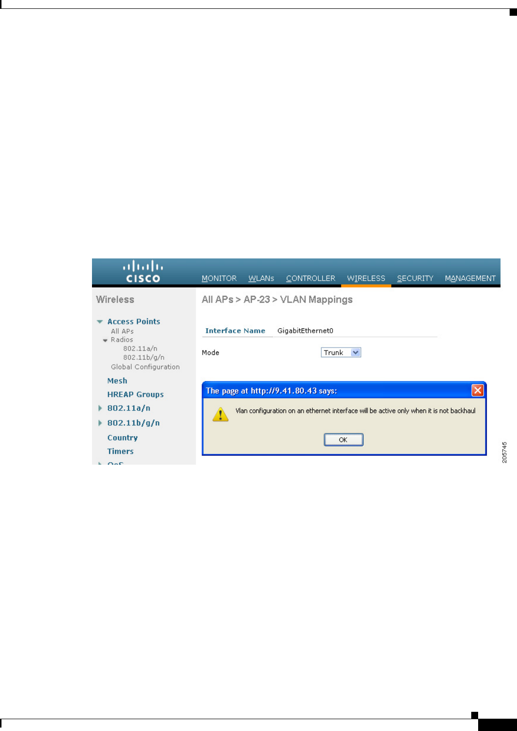
• No configuration changes are applied to any Ethernet interface acting as a backhaul. A warning
displays if you attempt to modify the backhaul’s configuration. The configuration is only applied
after the interface is no longer acting as a backhaul (see Figure 9-46).
Figure 9-46 Warning Message Displays for Backhaul Configuration Attempts
• No configuration is required to support VLAN tagging on any 802.11a backhaul Ethernet interface
within the mesh network as follows:
–
This includes the RAP uplink Ethernet port. The required configuration occurs automatically
using a registration mechanism.
–
Any configuration changes to an 802.11a Ethernet link acting as a backhaul are ignored and a
warning results. When the Ethernet link no longer functions as a backhaul, the modified
configuration is applied.
• VLAN configuration is not allowed on port-02-cable modem port of AP1500s (wherever
applicable). VLANs can be configured on ports 0 (PoE-in), 1 (PoE-out), and 3 (fiber).
• Up to 16 VLANs are supported on each sector. The cumulative number of VLANs supported by a
RAP’s children (MAP) cannot exceed 16.
• The switch port connected to the RAP must be a trunk:
–
The trunk port on the switch and the RAP trunk port must match.
–
The RAP must always connect to the native VLAN ID 1 on a switch. The RAP’s primary
Ethernet interface is by default the native VLAN of 1.

9-78
Cisco Wireless LAN Controller Configuration Guide
OL-21524-02
Chapter 9 Controlling Mesh Access Points
Configuring Advanced Features
–
The switch port in the wired network that is attached to the RAP (port 0–PoE in) must be
configured to accept tagged packets on its trunk port. The RAP forwards all tagged packets
received from the mesh network to the wired network.
–
No VLANs, other than those destined for the mesh sector, should be configured on the switch
trunk port.
• A configured VLAN on a MAP Ethernet port cannot function as a Management VLAN.
• Configuration is effective only when a mesh access point is in the CAPWAP RUN state and
VLAN-Transparent mode is disabled.
• Whenever there roaming or a CAPWAP restart, an attempt is made to apply configuration again.
VLAN Registration
To support a VLAN on a mesh access point, all the uplink mesh access points must also support the same
VLAN to allow segregation of traffic that belongs to different VLANs. The activity by which an mesh
access point communicates its requirements for a VLAN and gets response from a parent is known as
VLAN registration.
Note VLAN registration occurs automatically. No user intervention is required.
VLAN registration is summarized below:
1. Whenever an Ethernet port on a mesh access point is configured with a VLAN, the port requests its
parent to support that VLAN.
2. If the parent is able to support the request, it creates a bridge group for the VLAN and propagates
the request to its parent. This propagation continues until the RAP is reached.
3. When the request reaches the RAP, it checks whether it is able to support the VLAN request. If yes,
the RAP creates a bridge group and a subinterface on its uplink Ethernet interface to support the
VLAN request.
4. If the mesh access point is not able to support the VLAN request by its child, at any point, the mesh
access point replies with a negative response. This response is propagated to downstream mesh
access points until the mesh access point that requested the VLAN is reached.
5. Upon receiving negative response from its parent, the requesting mesh access point defers the
configuration of the VLAN. However, the configuration is stored for future attempts. Given the
dynamic nature of mesh, another parent and its uplink mesh access points might be able to support
it in the case of roaming or a CAPWAP reconnect.
Enabling Ethernet VLAN Tagging Using the GUI
You must enable Ethernet bridging before you can configure VLAN tagging. See the “Configuring
Ethernet Bridging” procedure on page 9-52.
To enable VLAN tagging on a RAP or MAP using the GUI, follow these steps:
Step 1 After enabling Ethernet bridging, choose Wireless > All APs.
Step 2 Click the AP name link of the mesh access point on which you want to enable VLAN tagging.
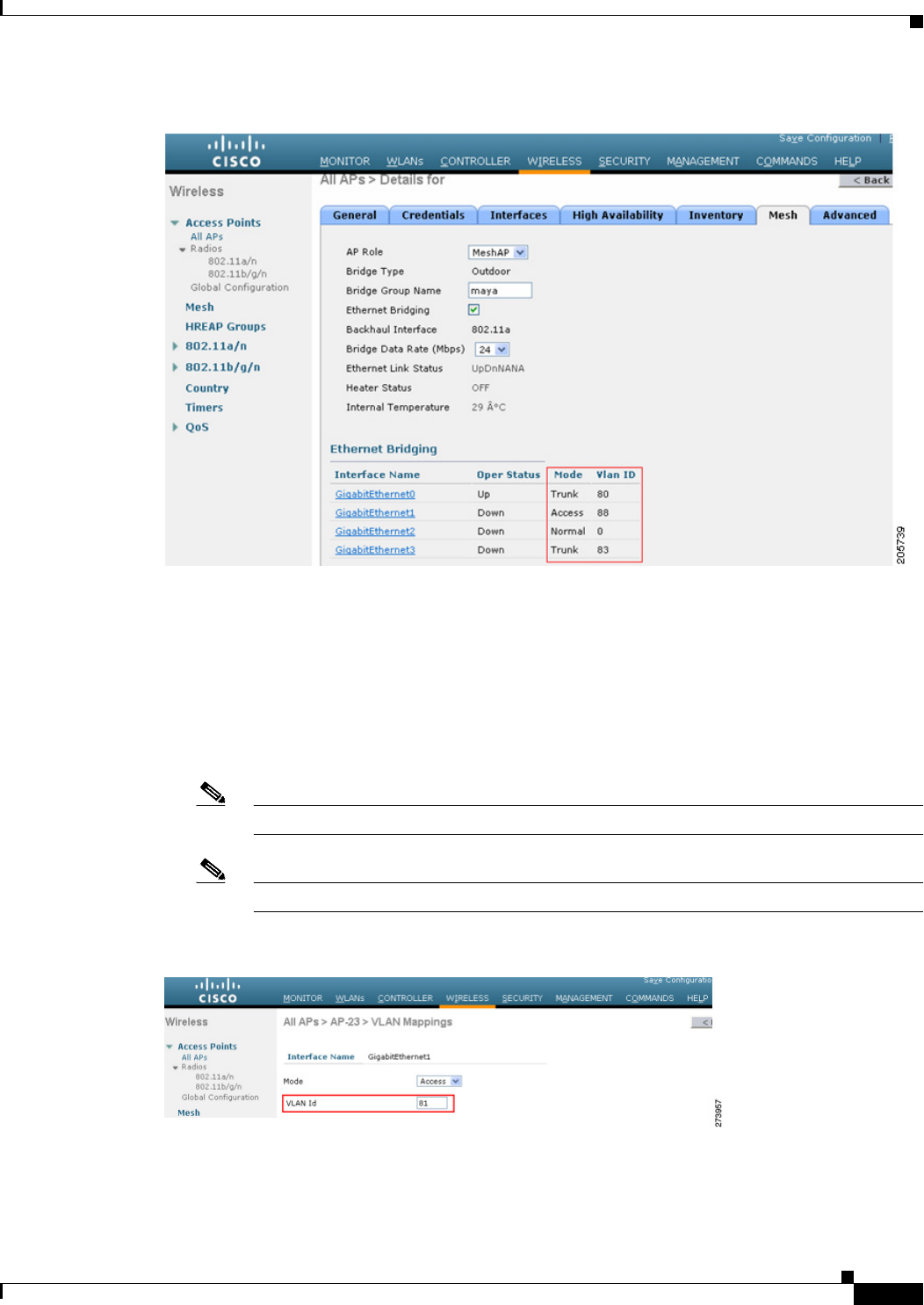
Step 3 On the details page, select the Mesh tab. (See Figure 9-47.)
9-79
Cisco Wireless LAN Controller Configuration Guide
OL-21524-02
Chapter 9 Controlling Mesh Access Points
Configuring Advanced Features
Figure 9-47 All APs > Details for (Mesh) Page
Step 4 Select the Ethernet Bridging check box to enable the feature and click Apply.
An Ethernet Bridging section appears at the bottom of the page listing each of the four Ethernet ports of
the mesh access point.
• If configuring a MAP access port, click, for example, gigabitEthernet1 (port 1-PoE out).
a. Select access from the mode drop-down list. (See Figure 9-48.)
b. Enter a VLAN ID. The VLAN ID can be any value between 1 and 4095.
c. Click Apply.
Note VLAN ID 1 is not reserved as the default VLAN.
Note A maximum of 16 VLANs are supported across all of a RAP’s subordinate MAP.
Figure 9-48 VLAN Access Mode
• If configuring a RAP or MAP trunk port, click gigabitEthernet0 (port 0-PoE in).
9-80
Cisco Wireless LAN Controller Configuration Guide
OL-21524-02
Chapter 9 Controlling Mesh Access Points
Configuring Advanced Features
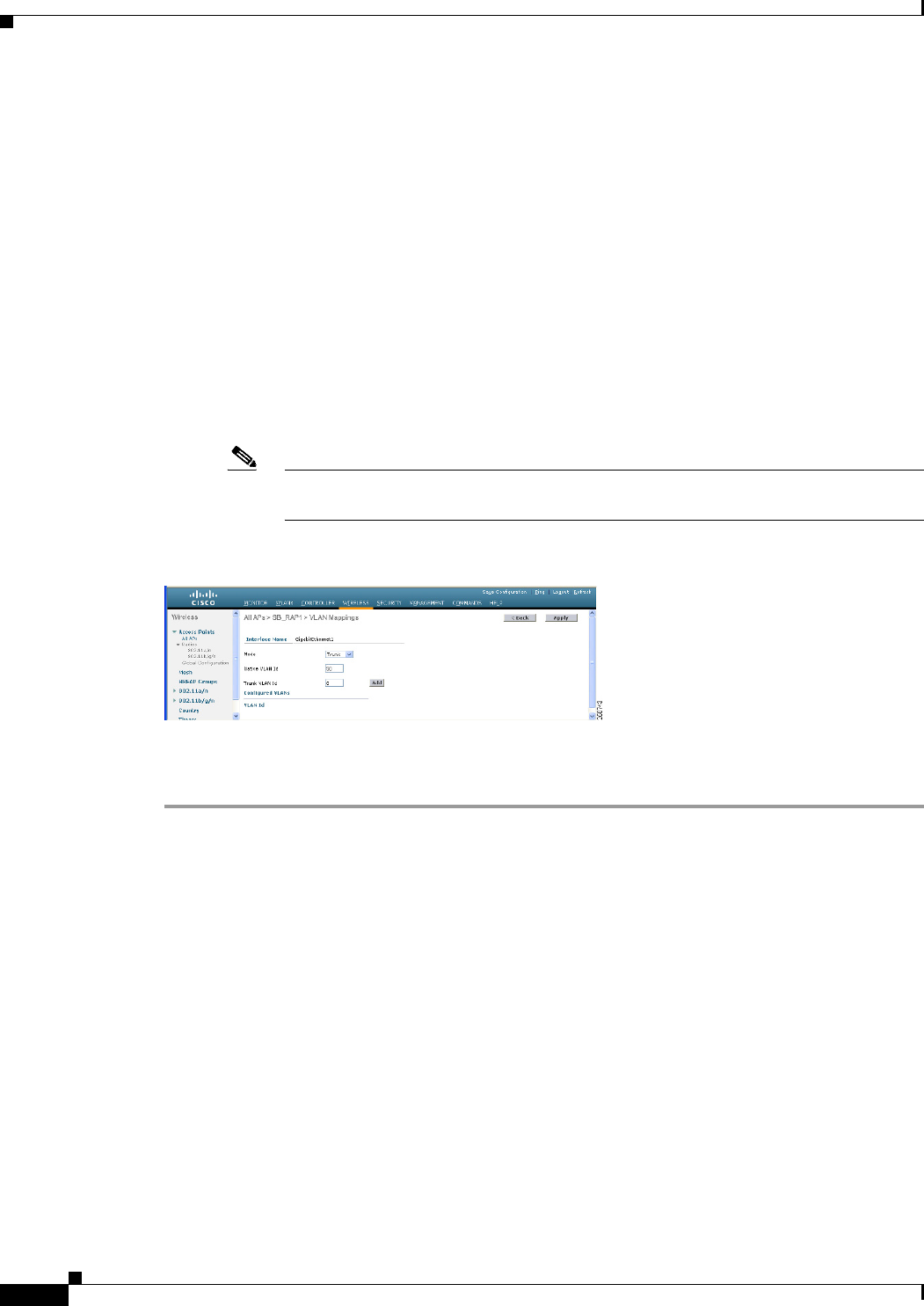
a. Select trunk from the mode drop-down list. (See Figure 9-49.)
b. Specify a native VLAN ID for incoming traffic. The native VLAN ID can be any value between
1 and 4095. Do not assign any value assigned to a user-VLAN (access).
c. Click Apply.
A trunk VLAN ID field and a summary of configured VLANs appears at the bottom of the
screen. The trunk VLAN ID field is for outgoing packets.
d. Specify a trunk VLAN ID for outgoing packets:
If forwarding untagged packets, do not change the default trunk VLAN ID value of zero.
(MAP-to-MAP bridging, campus environment)
If forwarding tagged packets, enter a VLAN ID (1 to 4095) that is not already assigned. (RAP
to switch on wired network).
e. Click Add to add the trunk VLAN ID to the allowed VLAN list. The newly added VLAN
displays under the Configured VLANs section on the page.
Note To remove a VLAN from the list, select the Remove option from the arrow drop-down
list to the right of the desired VLAN.
Figure 9-49 All APs > AP > VLAN Mappings Page
Step 5 Click Apply.
Step 6 Click Save Configuration to save your changes.
Configuring Ethernet VLAN Tagging Using the CLI
To configure a MAP access port, enter this command:
config ap ethernet 1 mode access enable AP1500-MAP 50
where AP1500-MAP is the variable AP_name and 50 is the variable access_vlan ID
To configure a RAP or MAP trunk port, enter this command:
config ap ethernet 0 mode trunk enable AP1500-MAP 60
where AP1500-MAP is the variable AP_name and 60 is the variable native_vlan ID
To add a VLAN to the VLAN allowed list of the native VLAN, enter this command:
config ap ethernet 0 mode trunk add AP1500-MAP3 65
where AP1500-MAP 3 is the variable AP_name and 65 is the variable VLAN ID
9-81
Cisco Wireless LAN Controller Configuration Guide
OL-21524-02
Chapter 9 Controlling Mesh Access Points
Configuring Advanced Features
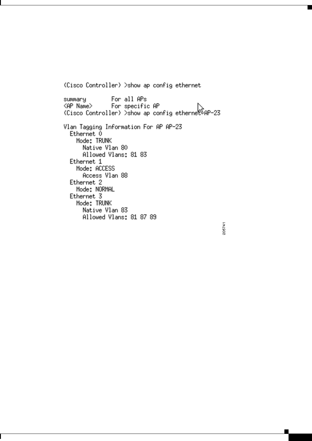
Viewing Ethernet VLAN Tagging Configuration Details Using the CLI
To view VLAN configuration details for Ethernet interfaces on a specific mesh access point (AP Name)
or all mesh access points (summary), enter one of the following commands:
To see if VLAN transparent mode is enabled or disabled, enter the following command:
9-82
Cisco Wireless LAN Controller Configuration Guide
OL-21524-02
Chapter 9 Controlling Mesh Access Points
Configuring Advanced Features
Workgroup Bridge Interoperability with Mesh Infrastructure
A workgroup bridge (WGB) is a small standalone unit that can provide a wireless infrastructure
connection for Ethernet-enabled devices. Devices that do not have a wireless client adapter to connect
to the wireless network can be connected to the WGB through the Ethernet port. The WGB is associated
with the root AP through the wireless interface, which means that wired clients get access to the wireless
network.
A WGB is used to connect wired networks over a single wireless segment by informing the mesh access
point of all the clients that the WGB has on its wired segment via IAPP messages. The data packets for
WGB clients contain an additional MAC address in the 802.11 header (4 MAC headers, versus the
normal 3 MAC data headers). The additional MAC in the header is the address of the WGB itself. This
additional MAC address is used to route the packet to and from the clients.
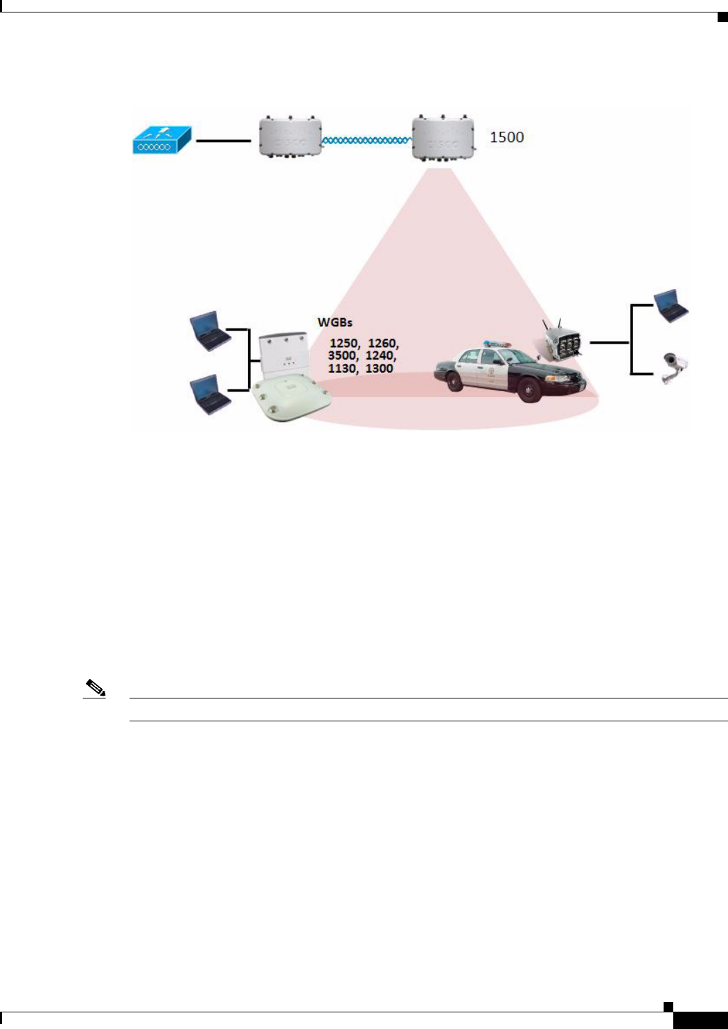
WGB association is supported on all radios of every mesh access point (see Figure 9-50).
9-83
Cisco Wireless LAN Controller Configuration Guide
OL-21524-02
Chapter 9 Controlling Mesh Access Points
Configuring Advanced Features
Figure 9-50 WGB Example
In the current architecture, while an autonomous AP functions as a workgroup bridge, only one radio
interface is used for controller connectivity, Ethernet interface for wired client connectivity, and other
radio interface for wireless client connectivity. dot11radio 1 (5 GHz) can be used to connect to a
controller (using the mesh infrastructure) and Ethernet interface for wired clients. dot11radio 0 (2.4
GHz) can be used for wireless client connectivity. Depending on the requirement, dot11radio 1 or
dot11radio 0 can be used for client association or controller connectivity.
With the 7.0 release, a wireless client on the second radio of the WGB is not dissociated by the WGB
upon losing its uplink to a wireless infrastructure or in a roaming scenario.
With two radios, one radio can be used for client access and the other radio can be used for accessing
the access points. Having two independent radios performing two independent functions provides you
better control and lowers the latency. Also, wireless clients on the second radio for the WGB do not get
disassociated by the WGB when an uplink is lost or in a roaming scenario. One radio has to be configured
as a Root AP (radio role) and the second radio has to be configured as a WGB (radio role).
Note If one radio is configured as a WGB, then the second radio cannot be a WGB or a repeater.
The following features are not supported for use with a WGB:
• Hybrid REAP
• Idle timeout
• Web authentication—If a WGB associates to a web-authentication WLAN, the WGB is added to the
exclusion list, and all of the WGB-wired clients are deleted (web-authentication WLAN is another
name for a guest WLAN).
• For wired clients behind the WGB, MAC filtering, link tests, and idle timeout

9-84
Cisco Wireless LAN Controller Configuration Guide
OL-21524-02
Chapter 9 Controlling Mesh Access Points
Configuring Advanced Features
Configuring Workgroup Bridges
A workgroup bridge (WGB) is used to connect wired networks over a single wireless segment by
informing the mesh access point of all the clients that the WGB has on its wired segment via IAPP
messages. In addition to the IAPP control messages, the data packets for WGB clients contain an extra
MAC address in the 802.11 header (4 MAC headers, versus the normal 3 MAC data headers). The extra
MAC in the header is the address of the workgroup bridge itself. This extra MAC address is used to route
the packet to and from the clients.
WGB association is supported on both the 2.4-GHz (802.11b/g) and 5-GHz (802.11a) radios on the
AP1522, and the 2.4-GHz (802.11b) and 4.9-GHz (public safety) radios on the AP1524PS;
Supported platforms are autonomous WGBs AP1130, AP1240, AP1310, and the Cisco 3200 Mobile
Router (hereafter referred to as Cisco 3200) which are configured as WGBs can associate with a mesh
access point. See the “Cisco Workgroup Bridges” section in Chapter 7 of the Cisco Wireless LAN
Controller Configuration Guide, Release 7.0.116.0 for configuration steps at
http://www.cisco.com/en/US/products/ps6366/products_installation_and_configuration_guides_list.ht
ml
Supported Workgroup Bridge Modes and Capacities
The supported WGB modes and capacities are as follows:
• The autonomous access points configured as WGBs must be running Cisco IOS release 12.4.25d-JA
or later.
Note If your mesh access point has two radios, you can only configure workgroup bridge mode
on one of the radios. We recommend that you disable the second radio. Workgroup bridge
mode is not supported on access points with three radios such as the AP1524SB.
• Client mode WGB (BSS) is supported; however, infrastructure WGB is not supported. The client
mode WGB is not able to trunk VLAN as in an infrastructure WGB.
• Multicast traffic is not reliably transmitted to WGB because no ACKs are returned by the client.
Multicast traffic is unicast to infrastructure WGB, and ACKs are received back.
• If one radio is configured as a WGB in a Cisco IOS access point, then the second radio cannot be a
WGB or a repeater.
• Mesh access points can support up to 200 clients including wireless clients, WGB, and wired clients
behind the associated WGB.
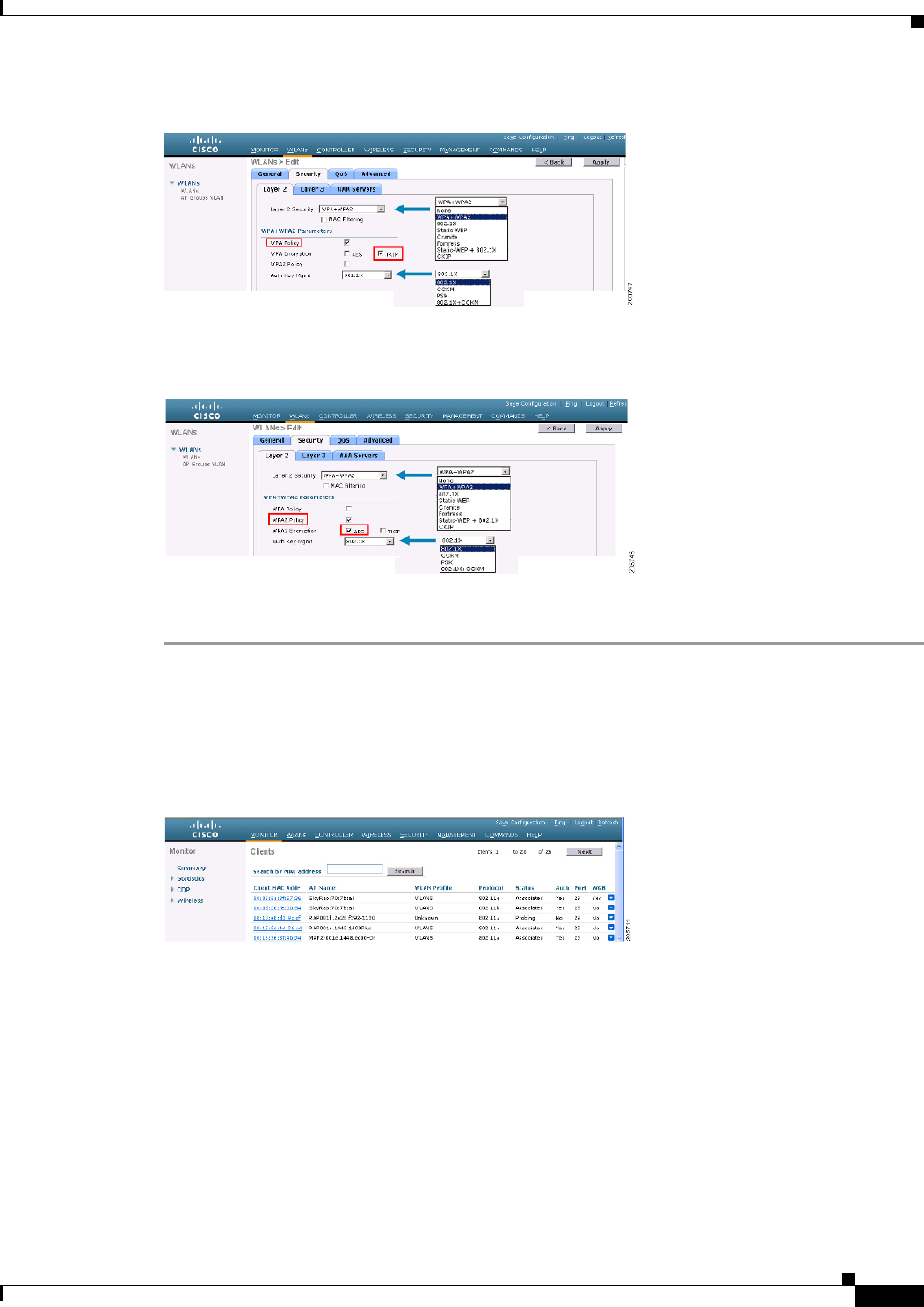
• A WGB cannot associate with mesh access points if the WLAN is configured with WPA1 (TKIP)
+WPA2 (AES), and the corresponding WGB interface is configured with only one of these
encryptions (either WPA1 or WPA2):
–
Figure 9-51 displays WPA security settings for WGB (controller GUI).
–
Figure 9-52 displays WPA-2 security settings for WGB (controller GUI).
9-85
Cisco Wireless LAN Controller Configuration Guide
OL-21524-02
Chapter 9 Controlling Mesh Access Points
Configuring Advanced Features
Figure 9-51 WPA Security Settings for a WGB
Figure 9-52 WPA-2 Security Settings for a WGB
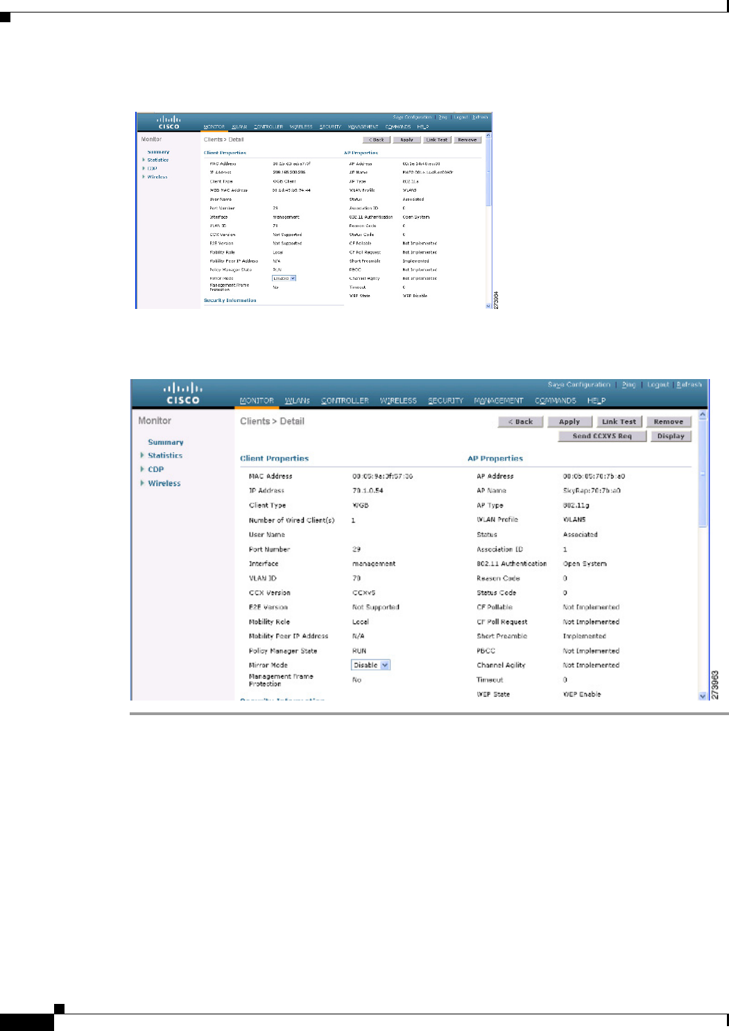
To view the status of a WGB client, follow these steps:
Step 1 Choose Monitor > Clients.
Step 2 On the client summary page, click on the MAC address of the client or search for the client using its
MAC address.
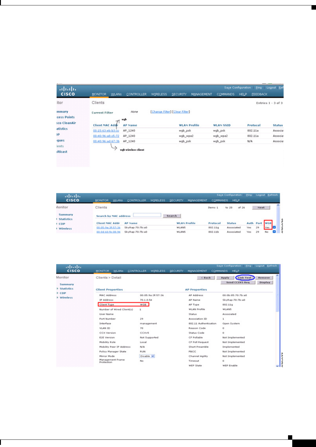
Step 3 In the page that appears, note that the client type is identified as a WGB (far right). (See Figure 9-53.)
Figure 9-53 Clients are Identified as a WGB
Step 4 Click on the MAC address of the client to view configuration details:
• For a wireless client, the page seen in Figure 9-54 appears.
• For a wired client, the page seen in Figure 9-55 appears.
9-86
Cisco Wireless LAN Controller Configuration Guide
OL-21524-02
Chapter 9 Controlling Mesh Access Points
Configuring Advanced Features
Figure 9-54 Monitor > Clients > Detail Page (Wireless WGB Client)
Figure 9-55 Monitor > Clients > Detail Page (Wired WGB Client)
Guidelines for Configuration
Follow these guidelines when you configure:
• We recommend using a 5-GHz radio for the uplink to Mesh AP infrastructure so you can take
advantage of a strong client access on two 5-GHz radios available on mesh access points. A 5-GHz
band allows more Effective Isotropic Radiated Power (EIRP) and is less polluted. In a two-radio
WGB, configure 5-GHz radio (radio 1) mode as WGB. This radio will be used to access the mesh
infrastructure. Configure the second radio 2.4-GHz (radio 0) mode as Root for client access.

9-87
Cisco Wireless LAN Controller Configuration Guide
OL-21524-02
Chapter 9 Controlling Mesh Access Points
Configuring Advanced Features
• On the Autonomous access points, only one SSID can be assigned to the native VLAN. You cannot
have multiple VLANs in one SSID on the autonomous side. SSID to VLAN mapping should be
unique because this is the way to segregate traffic on different VLANs. In a unified architecture,
multiple VLANs can be assigned to one WLAN (SSID).
• Only one WLAN (SSID) for wireless association of the WGB to the access point infrastructure is
supported. This SSID should be configured as an infrastructure SSID and should be mapped to the
native VLAN.
• A dynamic interface should be created in the controller for each VLAN configured in the WGB.
• A second radio (2.4-GHz) on the access point should be configured for client access. You have to
use the same SSID on both radios and map to the native VLAN. If you create a separate SSID, then
it is not possible to map it to a native VLAN, due to the unique VLAN/SSID mapping requirements.
If you try to map the SSID to another VLAN, then you do not have multiple VLAN support for
wireless clients.
• All Layer 2 security types are supported for the WLANs (SSIDs) for wireless client association in
WGB.
• This feature does not depend on the AP platform. On the controller side, both mesh and nonmesh
APs are supported.
• There is a limitation of 20 clients in the WGB. The 20-client limitation includes both wired and
wireless clients. If the WGB is talking to autonomous access points, then the client limit is very high.
• The controller treats the wireless and wired clients behind a WGB in the same manner. Features such
as MAC filtering and link test are not supported for wireless WGB clients from the controller.
• If required, you can run link tests for a WGB wireless client from an autonomous AP.
• Multiple VLANs for wireless clients associated to a WGB are not supported.
• Up to 16 multiple VLANs are supported for wired clients behind a WGB from the 7.0 release and
later releases.
• Roaming is supported for wireless and wired clients behind a WGB. The wireless clients on the other
radio will not be dissociated by the WGB when an uplink is lost or in a roaming scenario.
We recommend that you configure radio 0 (2.4 GHz) as a Root (one of the mode of operations for
Autonomous AP) and radio 1 (5 GHz) as a WGB.
Configuration Example
When you configure from the CLI, the following are mandatory:
• dot11 SSID (security for a WLAN can be decided based on the requirement).
• Map the subinterfaces in both the radios to a single bridge group.
Note A native VLAN is always mapped to bridge group 1 by default. For other VLANs, the bridge
group number matches the VLAN number; for example, for VLAN 46, the bridge group is 46.
• Map the SSID to the radio interfaces and define the role of the radio interfaces.
In the following example, one SSID (WGBTEST) is used in both radios, and the SSID is the
infrastructure SSID mapped to NATIVE VLAN 51. All radio interfaces are mapped to bridge group -1.
WGB1#config t
WGB1(config)#interface Dot11Radio1.51
WGB1(config-subif)#encapsulation dot1q 51 native
9-88
Cisco Wireless LAN Controller Configuration Guide
OL-21524-02
Chapter 9 Controlling Mesh Access Points
Configuring Advanced Features
WGB1(config-subif)#bridge-group 1
WGB1(config-subif)#exit
WGB1(config)#interface Dot11Radio0.51
WGB1(config-subif)#encapsulation dot1q 51 native
WGB1(config-subif)#bridge-group 1
WGB1(config-subif)#exit
WGB1(config)#dot11 ssid WGBTEST
WGB1(config-ssid)#VLAN 51
WGB1(config-ssid)#authentication open
WGB1(config-ssid)#infrastructiure-ssid
WGB1(config-ssid)#exit
WGB1(config)#interface Dot11Radio1
WGB1(config-if)#ssid WGBTEST
WGB1(config-if)#station-role workgroup-bridge
WGB1(config-if)#exit
WGB1(config)#interface Dot11Radio0
WGB1(config-if)#ssid WGBTEST
WGB1(config-if)#station-role root
WGB1(config-if)#exit
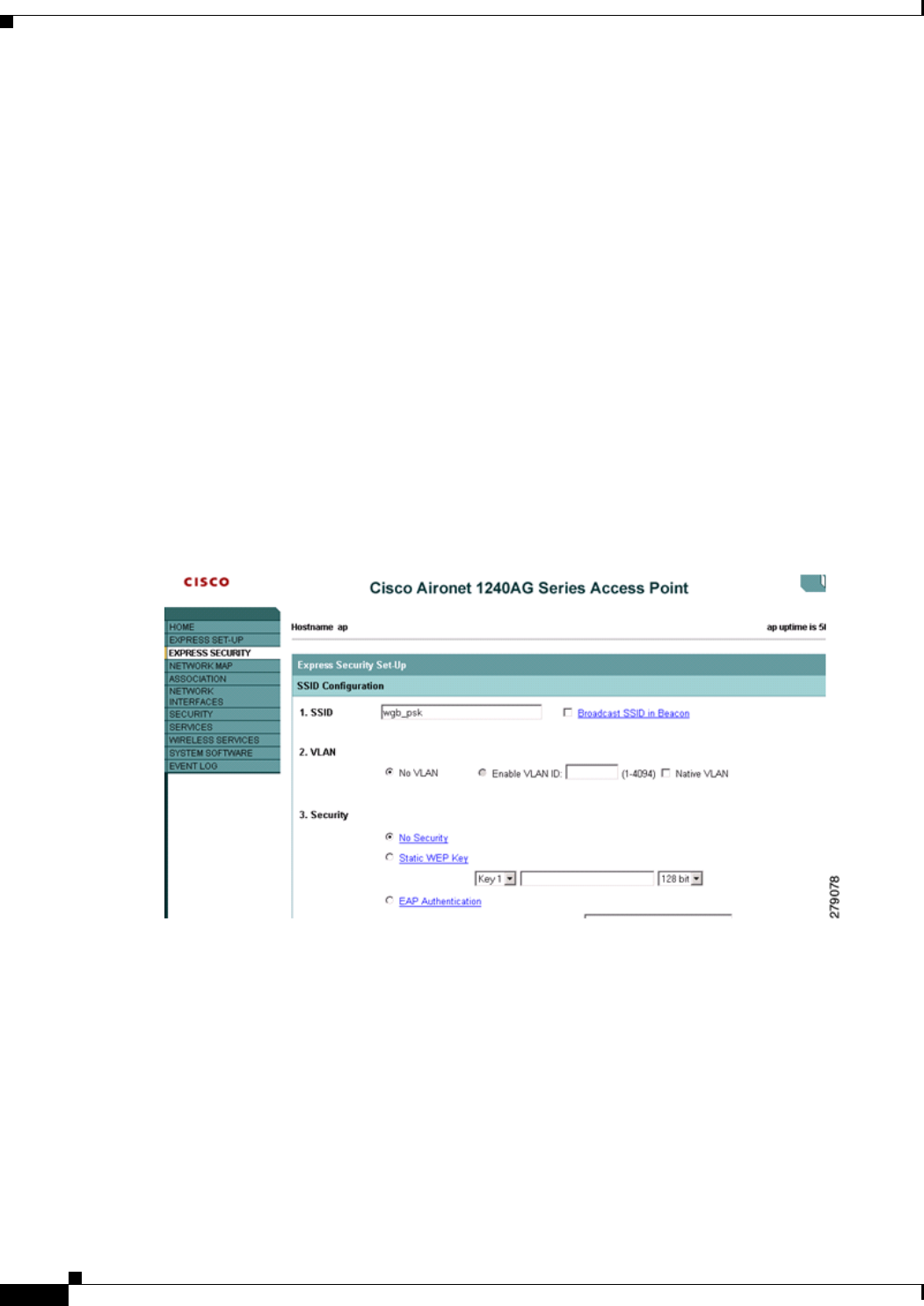
You can also use the GUI of an autonomous AP for configuration (see Figure 9-56). From the GUI,
subinterfaces are automatically created after the VLAN is defined.
Figure 9-56 SSID Configuration Page
WGB Association Check
Both the WGB association to the controller and the wireless client association to WGB can be verified
by entering the show dot11 associations client command in autonomous AP.
WGB#show dot11 associations client
802.11 Client Stations on Dot11Radio1:
SSID [WGBTEST] :
MAC Address IP Address Device Name Parent State
0024.130f.920e 209.165.200
.225
LWAPP-Paren
t
RAPSB -Assoc
9-89
Cisco Wireless LAN Controller Configuration Guide
OL-21524-02
Chapter 9 Controlling Mesh Access Points
Configuring Advanced Features
From the controller, choose Monitor > Clients. The WGB and the wireless/wired client behind the
WGB are updated and the wireless/wired client are shown as the WGB client, as shown in Figure 9-57,
Figure 9-58, and Figure 9-59.
Figure 9-57 Updated WGB Clients
Figure 9-58 Updated WGB Clients
Figure 9-59 Updated WGB Clients
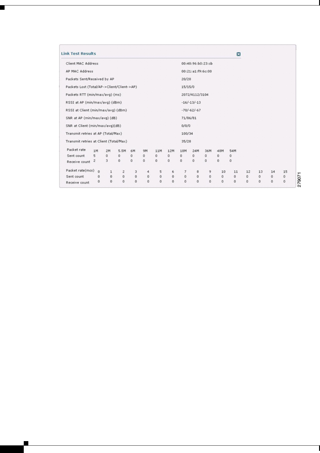
Link Test Result
Figure 9-60 shows the link test results.
9-90
Cisco Wireless LAN Controller Configuration Guide
OL-21524-02
Chapter 9 Controlling Mesh Access Points
Configuring Advanced Features
Figure 9-60 Link Test Results
A link test can also be run from the controller CLI using the following command:
(Cisco Controller) > linktest client mac address
Link tests from the controller are only limited to the WGB, and they cannot be run beyond the WGB
from the controller to a wired or wireless client connected to the WGB. You can run link tests for the
wireless client connected to the WGB from the WGB itself using the following command:
ap#dot11 dot11Radio 0 linktest target client mac
Start linktest to 0040.96b8.d462, 100 512 byte packets
ap#
Rates (Src/Tgt) 24Mb 0/5 36Mb 25/0 48Mb 73/0 54Mb 2/91
Linktest Done in 24.464 msec
POOR (4% lost) Time (msec) Strength (dBm) SNR Quality Retries
In Out In Out In Out
Sent: 100 Avg. 22 -37 -83 48 3Tot. 34 35
Lost to Tgt: 4 Max. 112 -34 -78 61 10 Max. 10 5
Lost to Src: 4 Min. 0 -40 -87 15 3

9-91
Cisco Wireless LAN Controller Configuration Guide
OL-21524-02
Chapter 9 Controlling Mesh Access Points
Configuring Advanced Features
WGB Wired/Wireless Client
You can also use the following commands to know the summary of WGBs and clients associated
associated with a Cisco lightweight access point:
(Cisco Controller) > show wgb summary
Number of WGBs................................... 2
(Cisco Controller) > show client summary
Number of Clients................................ 7
(Cisco Controller) > show wgb detail 00:1e:be:27:5f:e2
Number of wired client(s): 5
MAC Address IP Address AP Name Status WLAN Auth Protocol Clients
00:1d:70:97:bd:e8 209.165.200.225 c1240 Assoc 2Yes 802.11a 2
00:1e:be:27:5f:e2 209.165.200.226 c1240 Assoc 2Yes 802.11a 5
MAC Address AP Name Status WLAN/Guest-Lan Auth Protocol Port Wired
00:00:24:ca:a9:b4 R14 Associated 1Yes N/A 29 No
00:24:c4:a0:61:3a R14 Associated 1Yes 802.11a 29 No
00:24:c4:a0:61:f4 R14 Associated 1Yes 802.11a 29 No
00:24:c4:a0:61:f8 R14 Associated 1Yes 802.11a 29 No
00:24:c4:a0:62:0a R14 Associated 1Yes 802.11a 29 No
00:24:c4:a0:62:42 R14 Associated 1Yes 802.11a 29 No
00:24:c4:a0:71:d2 R14 Associated 1Yes 802.11a 29 No
MAC Address IP Address AP Name Mobility WLAN Auth
00:16:c7:5d:b4:8f Unknown c1240 Local 2No
00:21:91:f8:e9:ae 209.165.200.232 c1240 Local 2Yes
00:21:55:04:07:b5 209.165.200.234 c1240 Local 2Yes
00:1e:58:31:c7:4a 209.165.200.236 c1240 Local 2Yes
00:23:04:9a:0b:12 Unknown c1240 Local 2No

9-92
Cisco Wireless LAN Controller Configuration Guide
OL-21524-02
Chapter 9 Controlling Mesh Access Points
Configuring Advanced Features
Client Roaming
High-speed roaming of Cisco Compatible Extension (CX), version 4 (v4) clients is supported at speeds
up to 70 miles per hour in outdoor mesh deployments of AP1522s and AP1524s. An example application
might be maintaining communication with a terminal in an emergency vehicle as it moves within a mesh
public network.
Three Cisco CX v4 Layer 2 client roaming enhancements are supported:
• Access point assisted roaming—Helps clients save scanning time. When a Cisco CX v4 client
associates to an access point, it sends an information packet to the new access point listing the
characteristics of its previous access point. Roaming time decreases when the client recognizes and
uses an access point list built by compiling all previous access points to which each client was
associated and sent (unicast) to the client immediately after association. The access point list
contains the channels, BSSIDs of neighbor access points that support the client’s current SSID(s),
and time elapsed since disassociation.
• Enhanced neighbor list—Focuses on improving a Cisco CX v4 client’s roam experience and network
edge performance, especially when servicing voice applications. The access point provides its
associated client information about its neighbors using a neighbor-list update unicast message.
• Roam reason report—Enables Cisco CX v4 clients to report the reason why they roamed to a new
access point. It also allows network administrators to build and monitor a roam history.
Note Client roaming is enabled by default.
For more information, see the Enterprise Mobility Design Guide at
http://www.cisco.com/en/US/docs/solutions/Enterprise/Mobility/emob41dg/eMob4.1.pdf
WGB Roaming Guidelines
Follow these guidelines for WGB roaming:
• Configuring a WGB for roaming—If a WGB is mobile, you can configure it to scan for a better radio
connection to a parent access point or bridge. Use the ap(config-if)#mobile station period 3
threshold 50 command to configure the workgroup bridge as a mobile station.
When you enable this setting, the WGB scans for a new parent association when it encounters a poor
Received Signal Strength Indicator (RSSI), excessive radio interference, or a high frame-loss
percentage. Using these criteria, a WGB configured as a mobile station searches for a new parent
association and roams to a new parent before it loses its current association. When the mobile station
setting is disabled (the default setting), a WGB does not search for a new association until it loses
its current association.
• Configuring a WGB for Limited Channel Scanning—In mobile environments such as railroads, a
WGB instead of scanning all the channels is restricted to scan only a set of limited channels to
reduce the hand-off delay when the WGB roams from one access point to another. By limiting the
number of channels, the WGB scans only those required channels; the mobile WGB achieves and
maintains a continuous wireless LAN connection with fast and smooth roaming. This limited
channel set is configured using the ap(config-if)#mobile station scan set of channels.
This command invokes scanning to all or specified channels. There is no limitation on the maximum
number of channels that can be configured. The maximum number of channels that can be
configured is restricted only by the number of channels that a radio can support. When executed, the

9-93
Cisco Wireless LAN Controller Configuration Guide
OL-21524-02
Chapter 9 Controlling Mesh Access Points
Configuring Advanced Features
WGB scans only this limited channel set. This limited channel feature also affects the known
channel list that the WGB receives from the access point to which it is currently associated.
Channels are added to the known channel list only if they are also part of the limited channel set.
Configuration Example
The following example shows how to configure a roaming configuration:
ap(config)#interface dot11radio 1
ap(config-if)#ssid outside
ap(config-if)#packet retries 16
ap(config-if)#station role workgroup-bridge
ap(config-if)#mobile station
ap(config-if)#mobile station period 3 threshold 50
ap(config-if)#mobile station scan 5745 5765
Use the no mobile station scan command to restore scanning to all the channels.
Table 9-10 identifies mesh access points and their respective frequency bands that support WGB.
Troubleshooting Tips
If a wireless client is not associated with a WGB, use the following steps to troubleshoot the problem:
1. Verify the client configuration and ensure that the client configuration is correct.
2. Check the show bridge command output in autonomous AP, and confirm that the AP is reading the
client MAC address from the right interface.
3. Confirm that the subinterfaces corresponding to specific VLANs in different interfaces are mapped
to the same bridge group.
4. If required, clear the bridge entry using the clear bridge command (remember that this command
will remove all wired and wireless clients associated in a WGB and make them associate again).
Ta b l e 9-10 WGB Interoperability Chart
RAP/MAP WGB
Backhaul
MAR3200 802.11n Indoor APs 1130/1240 1310
4.9 GHz
(5, 10, 20
MHz)
5 GHz 2.4 GHz 5 GHz 2.4 GHz 5 GHz 2.4 GHz 5 GHz 2.4 GHz
1552/1552 No Yes Ye s Yes Yes Ye s Yes No Ye s
1524SB/1524SB No Yes Ye s Yes Ye s Ye s Yes No Ye s
1524PS/1524PS Yes No Ye s No Yes No Yes No Yes
1522/1522 Yes Yes Yes Yes Ye s Ye s Yes No Ye s
1524SB/1522 No Yes Yes Yes Yes Yes Ye s No Yes
1524PS/1522 No Yes Ye s Yes Yes Ye s Ye s No Yes
1522/1524SB No Yes Ye s Yes Yes Yes Ye s No Yes
1522/1524PS Yes No Ye s No Yes No Yes No Yes
1240/1130 No Yes Ye s Yes Yes Yes Ye s No Yes

9-94
Cisco Wireless LAN Controller Configuration Guide
OL-21524-02
Chapter 9 Controlling Mesh Access Points
Configuring Advanced Features
5. Check the show dot11 association command output and confirm that the WGB is associated with
the controller.
6. Ensure that the WGB has not exceeded its 20-client limitation.
In a normal scenario, if the show bridge and show dot11 association command outputs are as expected,
wireless client association should be successful.
Configuring Voice Parameters in Indoor Mesh Networks
You can configure call admission control (CAC) and QoS on the controller to manage voice and video
quality on the mesh network.
The indoor mesh access points are 802.11e capable, and QoS is supported on the local 2.4-GHz access
radio and the 5-GHz backhaul radio. CAC is supported on the backhaul and the CCXv4 clients (which
provides CAC between the mesh access point and the client).
Note Voice is supported only on indoor mesh networks. Voice is supported on a best-effort basis in the
outdoors in a mesh network.
CAC
CAC enables a mesh access point to maintain controlled quality of service (QoS) when the wireless LAN
is experiencing congestion. The Wi-Fi Multimedia (WMM) protocol deployed in CCXv3 ensures
sufficient QoS as long as the wireless LAN is not congested. However, to maintain QoS under differing
network loads, CAC in CCXv4 or later is required.
Note CAC is supported in Cisco Compatible Extensions (CCX) v4 or later. See Chapter 6 of the Cisco Wireless
LAN Controller Configuration Guide, Release 7.0 at
http://www.cisco.com/en/US/docs/wireless/controller/7.0/configuration/guide/c70sol.html
Two types of CAC are available for access points: bandwidth-based CAC and load-based CAC. All calls
on a mesh network are bandwidth-based, so mesh access points use only bandwidth-based CAC.
Bandwidth-based, or static CAC enables the client to specify how much bandwidth or shared medium
time is required to accept a new call. Each access point determines whether it is capable of
accommodating a particular call by looking at the bandwidth available and compares it against the
bandwidth required for the call. If there is not enough bandwidth available to maintain the maximum
allowed number of calls with acceptable quality, the mesh access point rejects the call.
QoS and DSCP Marking
Cisco supports 802.11e on the local access and on the backhaul. Mesh access points prioritize user traffic
based on classification, and therefore all user traffic is treated on a best-effort basis.
Resources available to users of the mesh vary, according to the location within the mesh, and a
configuration that provides a bandwidth limitation in one point of the network can result in an
oversubscription in other parts of the network.
Similarly, limiting clients on their percentage of RF is not suitable for mesh clients. The limiting
resource is not the client WLAN, but the resources available on the mesh backhaul.
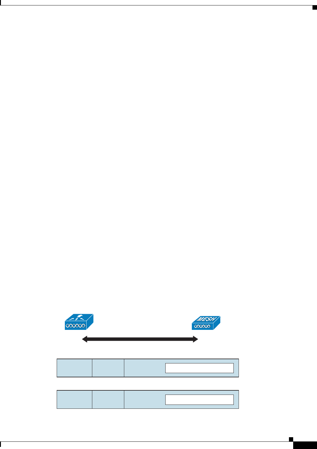
9-95
Cisco Wireless LAN Controller Configuration Guide
OL-21524-02
Chapter 9 Controlling Mesh Access Points
Configuring Advanced Features
Similar to wired Ethernet networks, 802.11 WLANs employ Carrier Sense Multiple Access (CSMA),
but instead of using collision detection (CD), WLANs use collision avoidance (CA), which means that
instead of each station trying to transmit as soon as the medium is free, WLAN devices will use a
collision avoidance mechanism to prevent multiple stations from transmitting at the same time.
The collision avoidance mechanism uses two values called CWmin and CWmax. CW stands for
contention window. The CW determines what additional amount of time an endpoint should wait, after
the interframe space (IFS), to attend to transmit a packet. Enhanced distributed coordination function
(EDCF) is a model that allows end devices that have delay-sensitive multimedia traffic to modify their
CWmin and CWmax values to allow for statically greater (and more frequent) access to the medium.
Cisco access points support EDCF-like QoS. This provides up to eight queues for QoS.
These queues can be allocated in several different ways, as follows:
• Based on TOS / DiffServ settings of packets
• Based on Layer 2 or Layer 3 access lists
• Based on VLAN
• Based on dynamic registration of devices (IP phones)
AP1500s, with Cisco controllers, provide a minimal integrated services capability at the controller, in
which client streams have maximum bandwidth limits, and a more robust differentiated services
(diffServ) capability based on the IP DSCP values and QoS WLAN overrides.
When the queue capacity has been reached, additional frames are dropped (tail drop).
Encapsulations
Several encapsulations are used by the mesh system. These encapsulations include CAPWAP control and
data between the controller and RAP, over the mesh backhaul, and between the mesh access point and
its client(s). The encapsulation of bridging traffic (noncontroller traffic from a LAN) over the backhaul
is the same as the encapsulation of CAPWAP data.
There are two encapsulations between the controller and the RAP. The first is for CAPWAP control, and
the second is for CAPWAP data. In the control instance, CAPWAP is used as a container for control
information and directives. In the instance of CAPWAP data, the entire packet, including the Ethernet
and IP headers, is sent in the CAPWAP container (see Figure 9-61).
Figure 9-61 Encapsulations
802.1/802.1P
Controller
802.1/802.1P
IP/IP DSCP CAPWAP
Encapsulation
IP/IP DSCP CAPWAP
Encapsulation
CAPWAP Control
CAPWAP Data
CAPWAP Control Information
Client Packet
205686
RAP
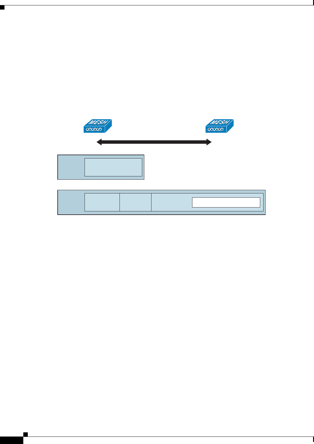
9-96
Cisco Wireless LAN Controller Configuration Guide
OL-21524-02
Chapter 9 Controlling Mesh Access Points
Configuring Advanced Features
For the backhaul, there is only one type of encapsulation, encapsulating MESH traffic. However, two
types of traffic are encapsulated: bridging traffic and CAPWAP control and data traffic. Both types of
traffic are encapsulated in a proprietary mesh header.
In the case of bridging traffic, the entire packet Ethernet frame is encapsulated in the mesh header (see
Figure 9-62).
All backhaul frames are treated identically, regardless of whether they are MAP to MAP, RAP to MAP,
or MAP to RAP.
Figure 9-62 Encapsulating Mesh Traffic
Queuing on the Mesh Access Point
The mesh access point uses a high speed CPU to process ingress frames, Ethernet, and wireless on a
first-come, first-serve basis. These frames are queued for transmission to the appropriate output device,
either Ethernet or wireless. Egress frames can be destined for either the 802.11 client network, the
802.11 backhaul network, or Ethernet.
AP1500s support four FIFOs for wireless client transmissions. These FIFOs correspond to the 802.11e
platinum, gold, silver, and bronze queues, and obey the 802.11e transmission rules for those queues. The
FIFOs have a user configurable queue depth.
The backhaul (frames destined for another outdoor mesh access point) uses four FIFOs, although user
traffic is limited to gold, silver, and bronze. The platinum queue is used exclusively for CAPWAP control
traffic and voice, and has been reworked from the standard 802.11e parameters for CWmin, CWmax, and
so on, to provide more robust transmission but higher latencies.
The 802.11e parameters for CWmin, CWmax, and so on, for the gold queue have been reworked to
provide lower latency at the expense of slightly higher error rate and aggressiveness. The purpose of
these changes is to provide a channel that is more conducive to video applications.
Frames that are destined for Ethernet are queued as FIFO, up to the maximum available transmit buffer
pool (256 frames). There is support for a Layer 3 IP Differentiated Services Code Point (DSCP), so
marking of the packets is there as well.
In the controller to RAP path for the data traffic, the outer DSCP value is set to the DSCP value of the
incoming IP frame. If the interface is in tagged mode, the controller sets the 802.1Q VLAN ID and
derives the 802.1p UP (outer) from 802.1p UP incoming and the WLAN default priority ceiling. Frames
with VLAN ID 0 are not tagged (see Figure 9-63).
Bridging Packet
Mesh
Header
802.1/802.1P IP/IP DSCP CAPWAP
Encapsulation
Mesh
Header CAPWAP Control/Data
205687
MAPRAP

9-97
Cisco Wireless LAN Controller Configuration Guide
OL-21524-02
Chapter 9 Controlling Mesh Access Points
Configuring Advanced Features
Figure 9-63 Controller to RAP Path
For CAPWAP control traffic the IP DSCP value is set to 46, and the 802.1p user priority is set to 7. Prior
to transmission of a wireless frame over the backhaul, regardless of node pairing (RAP/MAP) or
direction, the DSCP value in the outer header is used to determine a backhaul priority. The following
sections describe the mapping between the four backhaul queues the mesh access point uses and the
DSCP values shown in Backhaul Path QoS (see Table 9-11).
Note The platinum backhaul queue is reserved for CAPWAP control traffic, IP control traffic, and voice
packets. DHCP, DNS, and ARP requests are also transmitted at the platinum QoS level. The mesh
software inspects each frame to determine whether it is a CAPWAP control or IP control frame in order
to protect the platinum queue from use by non-CAPWAP applications.
For a MAP to the client path, there are two different procedures, depending on whether the client is a
WMM client or a normal client. If the client is a WMM client, the DSCP value in the outer frame is
examined, and the 802.11e priority queue is used (see Table 9-12).
If the client is not a WMM client, the WLAN override (as configured at the controller) determines the
802.11e queue (bronze, gold, platinum, or silver), on which the packet is transmitted.
For a client of a mesh access point, there are modifications made to incoming client frames in preparation
for transmission on the mesh backhaul or Ethernet. For WMM clients, a MAP illustrates the way in
which the outer DSCP value is set from an incoming WMM client frame (see Figure 9-64).
205688
802.1p UP Outer IP DSCP Outer
CAPWAP
Encapsulation
Incoming 802.1p UP IP DSCP Inner
Ta b l e 9-11 Backhaul Path QoS
DSCP Value Backhaul Queue
2, 4, 6, 8 to 23 Bronze
26, 32 to 63 Gold
46 to 56 Platinum
All others including 0 Silver
Ta b l e 9-12 MAP to Client Path QoS
DSCP Value Backhaul Queue
2, 4, 6, 8 to 23 Bronze
26, 32 to 45, 47 Gold
46, 48 to 63 Platinum
All others including 0 Silver

9-98
Cisco Wireless LAN Controller Configuration Guide
OL-21524-02
Chapter 9 Controlling Mesh Access Points
Configuring Advanced Features
Figure 9-64 MAP to RAP Path
The minimum value of the incoming 802.11e user priority and the WLAN override priority is translated
using the information listed in Table 9-13 to determine the DSCP value of the IP frame. For example, if
the incoming frame has as its value a priority indicating the gold priority, but the WLAN is configured
for the silver priority, the minimum priority of silver is used to determine the DSCP value.
If there is no incoming WMM priority, the default WLAN priority is used to generate the DSCP value
in the outer header. If the frame is an originated CAPWAP control frame, the DSCP value of 46 is placed
in the outer header.
With the 5.2 code enhancements, DSCP information is preserved in an AWPP header.
All wired client traffic is restricted to a maximum 802.1p UP value of 5, except DHCP/DNS and ARP
packets, which go through the platinum queue.
The non-WMM wireless client traffic gets the default QoS priority of its WLAN. The WMM wireless
client traffic may have a maximum 802.11e value of 6, but it must be below the QoS profile configured
for its WLAN. If admission control is configured, WMM clients must use TSPEC signaling and get
admitted by CAC.
The CAPWAPP data traffic carries wireless client traffic and has the same priority and treatment as
wireless client traffic.
Now that the DSCP value is determined, the rules described earlier for the backhaul path from the RAP
to the MAP are used to further determine the backhaul queue on which the frame is transmitted. Frames
transmitted from the RAP to the controller are not tagged. The outer DSCP values are left intact, as they
were first constructed.
Bridging Backhaul Packets
Bridging services are treated a little differently from regular controller-based services. There is no outer
DSCP value in bridging packets because they are not CAPWAP encapsulated. Therefore, the DSCP value
in the IP header as it was received by the mesh access point is used to index into the table as described
in the path from the mesh access point to the mesh access point (backhaul).
205689
IP DSCP Outer
CAPWAP
Encapsulation
Incoming 802.11e UP IP DSCP Inner
Ta b l e 9-13 DSCP to Backhaul Queue Mapping
DSCP Value 802.11e UP Backhaul Queue Packet Types
2, 4, 6, 8 to 23 1, 2 Bronze Lowest priority packets, if any
26, 32 to 34 4, 5 Gold Video packets
46 to 56 6, 7 Platinum CAPWAP control, AWPP,
DHCP/DNS, ARP packets, voice
packets
All others including 0 0, 3 Silver Best effort, CAPWAP data
packets

9-99
Cisco Wireless LAN Controller Configuration Guide
OL-21524-02
Chapter 9 Controlling Mesh Access Points
Configuring Advanced Features
Bridging Packets from and to a LAN
Packets received from a station on a LAN are not modified in any way. There is no override value for the
LAN priority. Therefore, the LAN must be properly secured in bridging mode. The only protection
offered to the mesh backhaul is that non-CAPWAP control frames that map to the platinum queue are
demoted to the gold queue.
Packets are transmitted to the LAN precisely as they are received on the Ethernet ingress at entry to the
mesh.
The only way to integrate QoS between Ethernet ports on AP1500 and 802.11a is by tagging Ethernet
packets with DSCP. AP1500s take the Ethernet packet with DSCP and places it in the appropriate
802.11e queue.
AP1500s do not tag DSCP itself:
• On the ingress port, the AP1500 sees a DSCP tag, encapsulates the Ethernet frame, and applies the
corresponding 802.11e priority.
• On the egress port, the AP1500 decapsulates the Ethernet frame, and places it on the wire with an
untouched DSCP field.
Ethernet devices, such as video cameras, should have the capability to mark the bits with DSCP value to
take advantage of QoS.
Note QoS only is relevant when there is congestion on the network.
Guidelines For Using Voice on the Mesh Network
Follow these guidelines when you use voice on the mesh network:
• Voice is supported only on indoor mesh networks in release 5.2, 6.0, 7.0, and 7.0.116.0. For
outdoors, voice is supported on a best-effort basis on a mesh infrastructure.
• When voice is operating on a mesh network, calls must not traverse more than two hops. Each sector
must be configured to require no more than two hops for voice.
• RF considerations for voice networks are as follows:
–
Coverage hole of 2 to 10 percent
–
Cell coverage overlap of 15 to 20 percent
–
Voice needs RSSI and SNR values that are at least 15 dB higher than data requirements
–
RSSI of -67 dBm for all data rates should be the goal for 11b/g/n and 11a/n
–
SNR should be 25 dB for the data rate used by client to connect to the AP
–
Packet error rate (PER) should be configured for a value of one percent or less
–
Channel with the lowest utilization (CU) must be used
• On the 802.11a/n or 802.11b/g/n > Global parameters page, you should do the following:
–
Enable dynamic target power control (DTPC).
–
Disable all data rates less than 11 Mbps.
• On the 802.11a/n or 802.11b/g/n > Voi c e parameters page, you should do the following:
–
Load-based CAC must be disabled.

9-100
Cisco Wireless LAN Controller Configuration Guide
OL-21524-02
Chapter 9 Controlling Mesh Access Points
Configuring Advanced Features
–
Enable admission control (ACM) for CCXv4 or v5 clients that have WMM enabled. Otherwise,
bandwidth-based CAC does not operate properly.
–
Set the maximum RF bandwidth to 50 percent.
–
Set the reserved roaming bandwidth to 6 percent.
–
Enable traffic stream metrics.
• On the 802.11a/n or 802.11b/g/n > EDCA parameters page, you should do the following:
–
Set the EDCA profile for the interface as voice optimized.
–
Disable low latency MAC.
• On the QoS > Profile page, you should do the following:
–
Create a voice profile and select 802.1Q as the wired QoS protocol type.
• On the WLANs > Edit > QoS page, you should do the following:
–
Select a QoS of platinum for voice and gold for video on the backhaul.
–
Select allowed as the WMM policy.
• On the WLANs > Edit > QoS page, you should do the following:
–
Select CCKM for authorization (auth) key management (mgmt) if you want to support fast
roaming. See the “Client Roaming” section on page 9-92.
• On the x > y page, you should do the following:
–
Disable voice active detection (VAD).
Voice Call Support in a Mesh Network
Table 9-14 shows the actual calls in a clean, ideal environment.
Table 9-15 shows the actual calls in a clean, ideal environment.
Ta b l e 9-14 Calls Possible with 1520 Series in 802.11a and 802.11b/g Radios1
1. Traffic was bidirectional 64K voice flows. VoCoder type: G.711, PER <= 1%. Network setup
was daisy-chained with no calls traversing more than 2 hops. No external interference.
No. of Calls 802.11a Radio 802.11b/g Radio
RAP 12 12
MAP1 710
MAP2 4 8
Ta b l e 9-15 Calls Possible with 1550 Series in 802.11a/n 802.11b/g/n Radios1
No. of Calls
802.11a/n
Radio 20 MHz
802.11a/n Radio
40 MHz
802.11b/g/n
Backhaul
Radio 20
MHz
802.11b/g/n
Backhaul Radio 40
MHz
RAP 20 35 20 20
MAP1 (First Hop) 10 20 15 20
MAP2 (Second Hop) 815 10 15
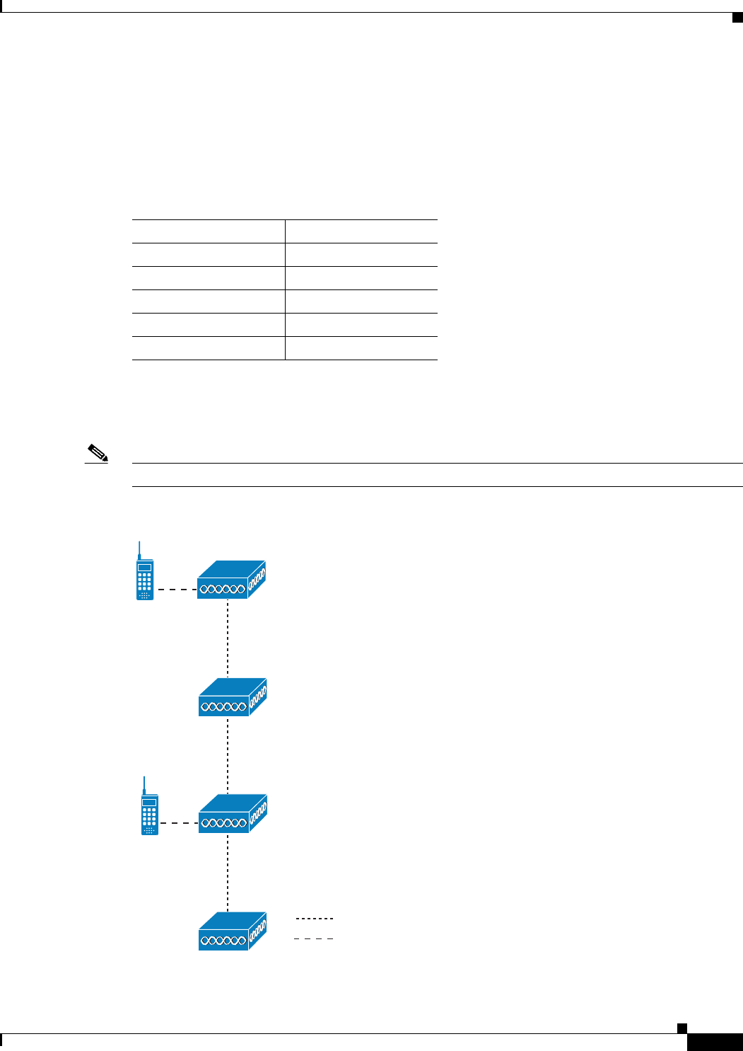
9-101
Cisco Wireless LAN Controller Configuration Guide
OL-21524-02
Chapter 9 Controlling Mesh Access Points
Configuring Advanced Features
While making a call, observe the MOS score of the call on the 7921 phone (see Table 9-16). A MOS
score between 3.5 and 4 is acceptable.
Viewing the Voice Details for Mesh Networks Using the CLI
Use the commands in this section to view details on voice and video calls on the mesh network:
Note See Figure 9-65 when using the CLI commands and viewing their output.
Figure 9-65 Mesh Network Example
1. Traffic was bidirectional 64K voice flows. VoCoder type: G.711, PER <= 1%. Network setup was daisy-chained
with no calls traversing more than 2 hops. No external interference.
Ta b l e 9-16 MOS Ratings
MOS rating User satisfaction
> 4.3 Very satisfied
4.0 Satisfied
3.6 Some users dissatisfied
3.1 Many users dissatisfied
< 2.58 —
802.11A
802.11B/G
RAP 01
MAP 02
272672
MAP 03
MESH
MESH
MAP 01
MESH
MESH

9-102
Cisco Wireless LAN Controller Configuration Guide
OL-21524-02
Chapter 9 Controlling Mesh Access Points
Configuring Advanced Features
• To view the total number of voice calls and the bandwidth used for voice calls on each RAP, enter
this command:
show mesh cac summary
Information similar to the following appears:
AP Name Slot# Radio BW Used/Max Calls
------------ ------- ----- ----------- -----
SB_RAP1 0 11b/g 0/23437 0
1 11a 0/23437 2
SB_MAP1 0 11b/g 0/23437 0
1 11a 0/23437 0
SB_MAP2 0 11b/g 0/23437 0
1 11a 0/23437 0
SB_MAP3 0 11b/g 0/23437 0
1 11a 0/23437 0
• To view the mesh tree topology for the network and the bandwidth utilization (used/maximum
available) of voice calls and video links for each mesh access point and radio, enter this command:
show mesh cac bwused {voice | video} AP_name
Information similar to the following appears:
AP Name Slot# Radio BW Used/Max
------------- ------- ----- -----------
SB_RAP1 0 11b/g 1016/23437
1 11a 3048/23437
|SB_MAP1 0 11b/g 0/23437
1 11a 3048/23437
|| SB_MAP2 0 11b/g 2032/23437
1 11a 3048/23437
||| SB_MAP3 0 11b/g 0/23437
1 11a 0/23437
Note The bars (|) to the left of the AP Name field indicate the number of hops that the MAP is
from its RAP.
Note When the radio type is the same, the backhaul bandwidth utilization (bw used/max) at each
hop is identical. For example, mesh access points map1, map2, map3, and rap1 are all on
the same radio backhaul (802.11a) and are using the same bandwidth (3048). All of the calls
are in the same interference domain. A call placed anywhere in that domain affects the
others.
• To view the mesh tree topology for the network and display the number of voice calls that are in
progress by mesh access point radio, enter this command:
show mesh cac access AP_name
Information similar to the following appears:
AP Name Slot# Radio Calls
------------- ------- ----- -----
SB_RAP1 0 11b/g 0
1 11a 0
| SB_MAP1 0 11b/g 0
1 11a 0
|| SB_MAP2 0 11b/g 1

9-103
Cisco Wireless LAN Controller Configuration Guide
OL-21524-02
Chapter 9 Controlling Mesh Access Points
Configuring Advanced Features
1 11a 0
||| SB_MAP3 0 11b/g 0
1 11a 0
Note Each call received by a mesh access point radio causes the appropriate calls summary
column to increment by one. For example, if a call is received on the 802.11b/g radio on
map2, then a value of one is added to the existing value in that radio’s calls column. In this
case, the new call is the only active call on the 802.11b/g radio of map2. If one call is active
when a new call is received, the resulting value is two.
• To view the mesh tree topology for the network and display the voice calls that are in progress, enter
this command:
show mesh cac callpath AP_name
Information similar to the following appears:
AP Name Slot# Radio Calls
------------- ------- ----- -----
SB_RAP1 0 11b/g 0
1 11a 1
| SB_MAP1 0 11b/g 0
1 11a 1
|| SB_MAP2 0 11b/g 1
1 11a 1
||| SB_MAP3 0 11b/g 0
1 11a 0
Note The calls column for each mesh access point radio in a call path increments by one. For
example, for a call that initiates at map2 (show mesh cac call path SB_MAP2) and
terminates at rap1 by way of map1, one call is added to the map2 802.11b/g and 802.11a
radio calls column, one call to the map1 802.11a backhaul radio calls column, and one call
to the rap1 802.11a backhaul radio calls column.
• To view the mesh tree topology of the network, the voice calls that are rejected at the mesh access
point radio due to insufficient bandwidth, and the corresponding mesh access point radio where the
rejection occurred, enter this command:
show mesh cac rejected AP_name
Information similar to the following appears:
AP Name Slot# Radio Calls
------------- ------- ----- -----
SB_RAP1 0 11b/g 0
1 11a 0
| SB_MAP1 0 11b/g 0
1 11a 0
|| SB_MAP2 0 11b/g 1
1 11a 0
||| SB_MAP3 0 11b/g 0
1 11a 0
Note If a call is rejected at the map2 802.11b/g radio, its calls column increments by one.

9-104
Cisco Wireless LAN Controller Configuration Guide
OL-21524-02
Chapter 9 Controlling Mesh Access Points
Configuring Advanced Features
• To view the number of bronze, silver, gold, platinum, and management queues active on the
specified access point, enter this command. The peak and average length of each queue are shown
as well as the overflow count.
show mesh queue-stats AP_name
Information similar to the following appears:
Queue Type Overflows Peak length Average length
---------- --------- ----------- --------------
Silver 0 1 0.000
Gold 0 4 0.004
Platinum 0 4 0.001
Bronze 0 0 0.000
Management 0 0 0.000
Overflows—The total number of packets dropped due to queue overflow.
Peak Length—The peak number of packets waiting in the queue during the defined statistics time
interval.
Average Length—The average number of packets waiting in the queue during the defined statistics
time interval.
Enabling Mesh Multicast Containment for Video
You can use the controller CLI to configure three mesh multicast modes to manage video camera
broadcasts on all mesh access points. When enabled, these modes reduce unnecessary multicast
transmissions within the mesh network and conserve backhaul bandwidth.
Mesh multicast modes determine how bridging-enabled access points MAP and RAP send multicasts
among Ethernet LANs within a mesh network. Mesh multicast modes manage non-CAPWAP multicast
traffic only. CAPWAP multicast traffic is governed by a different mechanism.
The three mesh multicast modes are as follows:
• Regular mode—Data is multicast across the entire mesh network and all its segments by
bridging-enabled RAP and MAP.
• In-only mode—Multicast packets received from the Ethernet by a MAP are forwarded to the RAP’s
Ethernet network. No additional forwarding occurs, which ensures that non-CAPWAP multicasts
received by the RAP are not sent back to the MAP Ethernet networks within the mesh network (their
point of origin), and MAP to MAP multicasts do not occur because they are filtered out.
Note When an HSRP configuration is in operation on a mesh network, we recommend the In-Out
multicast mode be configured.
• In-out mode—The RAP and MAP both multicast but in a different manner:
–
In-out mode is the default mode.
–
If multicast packets are received at a MAP over Ethernet, they are sent to the RAP; however,
they are not sent to other MAP over Ethernet, and the MAP to MAP packets are filtered out of
the multicast.
–
If multicast packets are received at a RAP over Ethernet, they are sent to all the MAPs and their
respective Ethernet networks. When the in-out mode is in operation, it is important to properly
partition your network to ensure that a multicast sent by one RAP is not received by another
RAP on the same Ethernet segment and then sent back into the network.

9-105
Cisco Wireless LAN Controller Configuration Guide
OL-21524-02
Chapter 9 Controlling Mesh Access Points
Configuring Advanced Features
Note If 802.11b clients need to receive CAPWAP multicasts, then multicast must be enabled
globally on the controller as well as on the mesh network (using the config network
multicast global enable CLI command). If multicast does not need to extend to 802.11b
clients beyond the mesh network, the global multicast parameter should be disabled (using
the config network multicast global disable CLI command).
Enabling Multicast on the Mesh Network Using the CLI
To enable multicast mode on the mesh network to receive multicasts from beyond the mesh networks,
enter these commands:
config network multicast global enable
config mesh multicast {regular | in | in-out}
To enable multicast mode only the mesh network (multicasts do not need to extend to 802.11b clients
beyond the mesh network), enter these commands:
config network multicast global disable
config mesh multicast {regular | in | in-out}
Note Multicast for mesh networks cannot be enabled using the controller GUI.
IGMP Snooping
IGMP snooping delivers improved RF usage through selective multicast forwarding and optimizes
packet forwarding in voice and video applications.
A mesh access point transmits multicast packets only if a client is associated with the mesh access point
that is subscribed to the multicast group. So, when IGMP snooping is enabled, only that multicast traffic
relevant to given hosts is forwarded.
To enable IGMP snooping on the controller, enter the following command:
configure network multicast igmp snooping enable
A client sends an IGMP join that travels through the mesh access point to the controller. The controller
intercepts the join and creates a table entry for the client in the multicast group. The controller then
proxies the IGMP join through the upstream switch or router.
You can query the status of the IGMP groups on a router by entering the following command:
router# show ip gmp groups
IGMP Connected Group Membership
Group Address Interface Uptime Expires Last Reporter
233.0.0.1 Vlan119 3w1d 00:01:52 10.1.1.130
For Layer 3 roaming, an IGMP query is sent to the client’s WLAN. The controller modifies the client’s
response before forwarding and changes the source IP address to the controller’s dynamic interface IP
address.
The network hears the controller’s request for the multicast group and forwards the multicast to the new
controller.
For more information about video, see the following:

9-106
Cisco Wireless LAN Controller Configuration Guide
OL-21524-02
Chapter 9 Controlling Mesh Access Points
Configuring Advanced Features
• Video Surveillance over Mesh Deployment Guide:
http://www.cisco.com/en/US/tech/tk722/tk809/technologies_tech_note09186a0080b02511.shtml
• Cisco Unified Wireless Network Solution: VideoStream Deployment Guide:
http://www.cisco.com/en/US/products/ps10315/products_tech_note09186a0080b6e11e.shtml
Locally Significant Certificates for Mesh APs
Until the 7.0 release, mesh APs supported only the Manufactured Installed Certificate (MIC) to
authenticate and get authenticated by controllers to join the controller. You might have had to have your
own public key infrastructure (PKI) to control CAs, to define policies, to define validity periods, to
define restrictions and usages on the certificates that are generated, and get these certificates installed
on the APs and controllers. After these customer-generated or locally significant certificates (LSCs) are
present on the APs and controllers, the devices start using these LSCs, to join, authenticate, and derive
a session key. Cisco supported normal APs from the 5.2 release and later releases and extended the
support for mesh APs as well from the 7.0 release.
With the 7.0.116.0 release, the following functionality has been added:
• Graceful fallback to MIC if APs are unable to join the controller with LSC certificates—Local APs
try to join a controller with an LSC for the number of times that are configured on the controller (the
default value is 3). After these trials, the AP deletes the LSC and tries to join a controller with an
MIC.
Mesh APs try to join a controller with an LSC until its lonely timer expires and the AP reboots. The
lonely timer is set for 40 minutes. After the reboot, the AP tries to join a controller with an MIC. If
the AP is again not able to join a controller with an MIC in 40 minutes, the AP reboots and then tries
to join a controller with an LSC.
Note An LSC in mesh APs is not deleted. An LSC is deleted in mesh APs only when the LSC is
disabled on the controller, which causes the APs to reboot.
• Over the air provisioning of MAPs.
Guidelines for Configuration
Follow these guidelines when using LSCs for mesh APs:
• This feature does not remove any preexisting certificates from an AP. It is possible for an AP to have
both LSC and MIC certificates.
• After an AP is provisioned with an LSC, it does not read in its MIC certificate on boot-up. A change
from an LSC to an MIC will require the AP to reboot. APs do it for a fallback if they cannot be joined
with an LSC.
• Provisioning an LSC on an AP does not require an AP to turn off its radios, which is vital for mesh
APs, which may get provisioned over-the-air.
• Because mesh APs need a dot1x authentication, a CA and ID certificate is required on the server (in
the controller or third-party server depending on the configuration).
• LSC provisioning will be supported only over Ethernet. You have to connect the mesh AP to the
controller through Ethernet and get the LSC certificate provisioned. After the LSC becomes the
default, an AP can be connected over-the-air to the controller using the LSC certificate.

9-107
Cisco Wireless LAN Controller Configuration Guide
OL-21524-02
Chapter 9 Controlling Mesh Access Points
Configuring Advanced Features
Differences Between LSCs for Mesh APs and Normal APs
CAPWAP APs use LSC for DTLS setup during a JOIN irrespective of the AP mode. Mesh APs also use
the certificate for mesh security, which involves a dot1x authentication with the controller (or an external
AAA server), through the parent AP. After the mesh APs are provisioned with an LSC, they need to use
the LSC for this purpose because MIC will not be read in.
Mesh APs use a statically configured dot1x profile to authenticate.
This profile is hardcoded to use "cisco" as the certificate issuer. This profile needs to be made
configurable so that vendor certificates can be used for mesh authentication (enter the config local-auth
eap-profile cert-issuer vendor "prfMaP1500LlEAuth93" command).
You must enter the config mesh lsc enable/disable command to enable or disable an LSC for mesh APs.
This command will cause all the mesh APs to reboot.
Note An LSC on mesh is open for very specific Oil and Gas customers with the 7.0 release. Initially, it is a
hidden feature. The config mesh lsc enable/disable is a hidden command. Also, the config local-auth
eap-profile cert-issuer vendor "prfMaP1500LlEAuth93" command is a normal command, but the
"prfMaP1500LlEAuth93" profile is a hidden profile, and is not stored on the controller and is lost after
the controller reboot.
Certificate Verification Process in LSC AP
LSC-provisioned APs have both LSC and MIC certificates, but the LSC certificate will be the default
one. The verification process consists of the following two steps:
1. The controller sends the AP the MIC device certificate, which the AP verifies with the MIC CA.
2. The AP sends the LSC device certificate to the controller, which the controller verifies with the LSC
CA.
Configuring an LSC Using the CLI
To configure LSC, follow these steps:
Step 1 Enable LSC and provision the LSC CA certificate in the controller.
Step 2 Enter the following command:
config local-auth eap-profile cert-issuer vendor "prfMaP1500LlEAuth93"
Step 3 Turn on the feature by entering the following command:
config mesh lsc enable/disable
Step 4 Install the CA and ID cert on the controller (or any other authentication server) from the same certificate
server.
Step 5 Connect the mesh AP through Ethernet and provision for an LSC certificate.
Step 6 Let the mesh AP get a certificate and join the controller using the LSC certificate. See Figure 9-66 and
Figure 9-67.
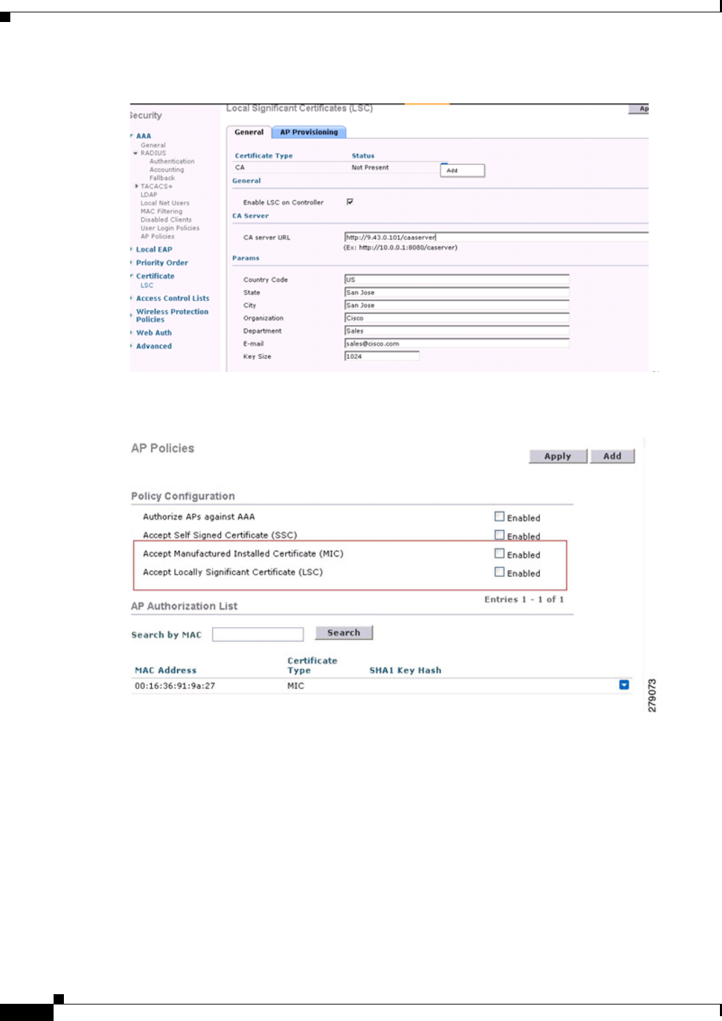
9-108
Cisco Wireless LAN Controller Configuration Guide
OL-21524-02
Chapter 9 Controlling Mesh Access Points
Configuring Advanced Features
Figure 9-66 Local Significant Certificate
Figure 9-67 AP Policy Configuration
LSC-Related Commands
The following commands are related to LSCs:
• config certificate lsc enable|disable
–
enable—To enable an LSC on the system.
–
disable—To disable an LSC on the system. Use this keyword to remove the LSC device
certificate and send a message to an AP, to do the same and disable an LSC, so that subsequent
joins could be made using the MIC/SSC. The removal of the LSC CA cert on the WLC should
be done explicitly by using the CLI to accommodate any AP that has not transitioned back to
the MIC/SSC.
• config certificate lsc ca-server "URL-Path"

9-109
Cisco Wireless LAN Controller Configuration Guide
OL-21524-02
Chapter 9 Controlling Mesh Access Points
Configuring Advanced Features
This command configures the URL to the CA server for getting the certificates. The URL contains
either the domain name or the IP address, port number (typically=80), and the CGI-PATH. The
following format is an example:
http://ipaddr:port/cgi-path
Only one CA server is allowed to be configured. The CA server has to be configured to provision an
LSC.
• config certificate lsc ca-server delete
This command deletes the CA server configured on the WLC.
• config certificate lsc ca-cert {add | delete}
This command adds or deletes the LSC CA certificate into/from the WLC's CA certificate database
as follows:
–
add—Queries the configured CA server for a CA certificate using the SSCEP getca operation,
and gets into the WLC and installs it permanently into the WLC database. If installed, this CA
certificate is used to validate the incoming LSC device certificate from the AP.
–
delete—Deletes the LSC CA certificate from the WLC database.
• config certificate lsc subject-params Country State City Orgn Dept Email
This command configures the parameters for the device certificate that will be created and installed
on the controller and the AP.
All of these strings have 64 bytes, except for the Country that has a maximum of 3 bytes. The
Common Name will be autogenerated using its Ethernet MAC address. This should be given prior
to the creation of the controller device certificate request.
The above parameters are sent as an LWAPP payload to the AP, so that the AP can use these
parameters to generate the certReq. The CN is autogenerated on the AP using the current MIC/SSC
"Cxxxx-MacAddr" format, where xxxx is the product number.
• config certificate lsc other-params keysize validity
The keysize and validity configurations have defaults. Therefore, it is not mandatory to configure
them.
1. The keysize can be from 360 to 2048 (the default is 2048 bits).
2. The validity period can be configured from 1 to 20 years (the default is 10 years).
• config certificate lsc ap-provision enable|disable
This command enables or disables the provisioning of the LSCs on the APs if the APs just joined
using the SSC/MIC. If enabled, all APs that join and do not have the LSC will get provisioned.
If disabled, no more automatic provisioning will be done. This command does not affect the APs,
which already have LSCs in them.
• config certificate lsc ra-cert add|delete
This command is recommended when the CA server is a Cisco IOS CA server. The WLC can use
the RA to encrypt the certificate requests and make communication more secure. RA certificates are
not currently supported by other external CA servers, such as MSFT.
–
add—Queries the configured CA server for an RA certificate using the SCEP operation and
installs it into the WLC Database. This keyword is used to get the certReq signed by the CA.
–
delete—Deletes the LSC RA certificate from the WLC database.
• config auth-list ap-policy lsc enable/disable

9-110
Cisco Wireless LAN Controller Configuration Guide
OL-21524-02
Chapter 9 Controlling Mesh Access Points
Configuring Advanced Features
After getting the LSC, an AP tries to join the WLC. Before the AP tries to join the WLC, this
command must be executed on the WLC console. Execution of this command is mandatory. By
default, the config auth-list ap-policy lsc command is in the disabled state, and in the disabled state,
the APs are not allowed to join the WLC using the LSC.
• config auth-list ap-policy mic enable|disable
After getting the MIC, an AP tries to join the WLC. Before the AP tries to join the WLC, this
command must be executed on the WLC console. Execution of this command is mandatory. By
default, the config auth-list ap-policy mic command is in the enabled state. If an AP cannot join
because of the enabled state, this log message in the WLC side is displayed: LSC/MIC AP is not
allowed to join by config.
Controller CLI show Commands
The following are the WLC show commands:
• show certificate lsc summary
This command displays the LSC certificates installed on the WLC. It would be the CA certificate,
device certificate, and optionally, an RA certificate if the RA certificate has also been installed. It
also indicates if an LSC is enabled or not.
• show certificate lsc ap-provision
This command displays the status of the provisioning of the AP, whether it is enabled or disabled,
and whether a provision list is present or not.
• show certificate lsc ap-provision details
This command displays the list of MAC addresses present in the AP provisioning lists.
Controller GUI Security Settings
Although the settings are not directly related to the feature, it may help you in achieving the desired
behavior with respect to APs provisioned with an LSC.
Figure 9-68 shows three possible cases for mesh AP MAC authorization and EAP.
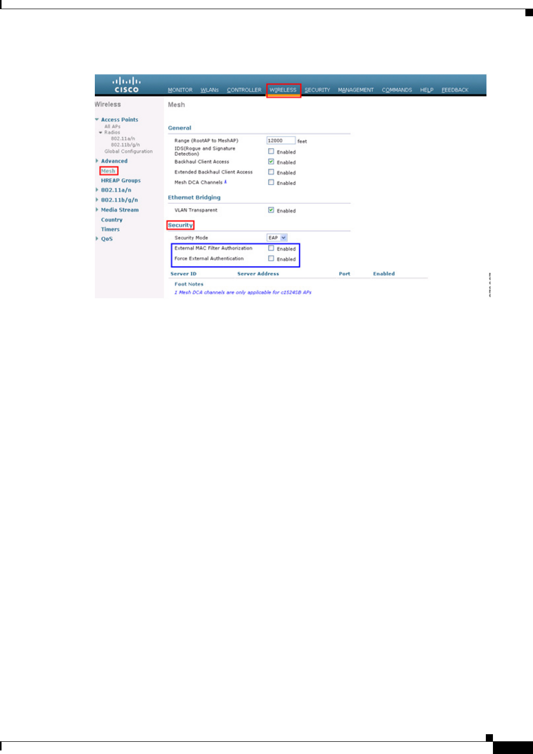
9-111
Cisco Wireless LAN Controller Configuration Guide
OL-21524-02
Chapter 9 Controlling Mesh Access Points
Configuring Advanced Features
Figure 9-68 Possible Cases for Mesh AP MAC Authorization and EAP
• Case 1—Local MAC Authorization and Local EAP Authentication
Add the MAC address of RAP/MAP to the controller MAC filter list.
Example:
(Cisco Controller) > config macfilter mac-delimiter colon
(Cisco Controller) > config macfilter add 00:0b:85:60:92:30 0 management
• Case 2—External MAC Authorization and Local EAP authentication
Enter the following command on the WLC:
(Cisco Controller) > config mesh security rad-mac-filter enable
or
Check only the external MAC filter authorization on the GUI page and follow these guidelines:
–
Do not add the MAC address of the RAP/MAP to the controller MAC filter list.
–
Configure the external radius server details on the WLC.
–
Enter the config macfilter mac-delimiter colon command configuration on the WLC.
–
Add the MAC address of the RAP/MAP in the external radius server in the following format:
User name: 11:22:33:44:55:66 Password : 11:22:33:44:55:66
• Case 3—External EAP authentication
Configure the external radius server details on the WLC and apply the following configuration on
the controller:
(Cisco Controller) > config mesh radius-server index enable
(Cisco Controller) > config mesh security force-ext-auth enable
Add the user ID and password on the AAA server in the (<platform name string>-<Ethernet mac
address hex string>) format for EAP Authentication.

9-112
Cisco Wireless LAN Controller Configuration Guide
OL-21524-02
Chapter 9 Controlling Mesh Access Points
Slot Bias Options
If it is a Cisco IOS AP, it should be in the following format:
username: c1240-112233445566 and password: c1240-112233445566 for 1240 platform APs
username: c1520-112233445566 and password: c1520-112233445566 for 1520 platform APs
For 1510 VxWorks-based AP, it should be in the following format:
username: 112233445566 and password: 112233445566
Deployment Guidelines
Follow these guidelines during deployment:
• When using local authorization, the controller should be installed with the vendor's CA and device
certificate.
• When using an external AAA server, the controller should be installed with the vendor’s CA and
device certificate.
• Mesh security should be configured to use ‘vendor’ as the cert-issuer.
• MAPs cannot move from an LSC to an MIC when they fall back to a backup controller.
The config mesh lsc enable|disable command is required to enable or disable an LSC for mesh APs.
This command causes all the mesh APs to reboot. Currently, disabling this command may also reboot
nonmesh APs.
Slot Bias Options
When a 1524SB AP is switched on, either slot 1 or slot 2 can be used for an uplink depending on the
strength of the signal. AWPP treats both slots equally. For a MAP, slot 2 is the preferred (biased) uplink
slot, that is, the slot that is used to connect to the parent AP. Slot 1 is the preferred downlink slot. When
both radio slots are available for use and if slot 1 is used for an uplink backhaul, a 15-minute timer is
started. At the end of 15 minutes, the AP scans for a channel in slot 2 so that slot 2 might be used for an
uplink backhaul again. This process is called slot bias.
We recommend that you use directional antenna on slot 2 for a proper linear functionality. We also
recommend that you ensure that slot 2 is selected for a strong uplink. However, there may be some
scenarios where directional antennas are used on both the backhaul radios for mobility. When the AP is
powered on, the parent can be selected in either direction. If slot 1 is selected, the AP should not go to
the scanning mode after 15 minutes, that is, you should disable the slot bias.
Disabling Slot Bias
In the 7.0.116.0 release, you can use the config mesh slot-bias disable to disable slot bias so that the
APs can be stable on slot 1.
To disable slot bias, enter the following command:
(Cisco Controller) > config mesh slot-bias disable
Note The slot bias is enabled by default.

9-113
Cisco Wireless LAN Controller Configuration Guide
OL-21524-02
Chapter 9 Controlling Mesh Access Points
Slot Bias Options
Usage Guidelines
Follow these guidelines for the config mesh slot-bias disable command:
• The config mesh slot-bias disable command is a global command and is applicable to all 1524SB
APs associated with the same controller.
• Slot bias is applicable only when both slot 1 and slot 2 are usable. If a slot radio does not have a
channel that is available because of dynamic frequency selection (DFS), the other slot takes up both
the uplink and downlink roles.
• If slot 2 is not available because of hardware issues, slot bias functions normally. Take corrective
action by disabling the slot bias or fixing the antenna.
• A 15-minute timer is initiated (slot bias) only when slot 1 and slot 2 are usable (have channels to
operate).
• The 15-minute timer is not initiated if slot 2 cannot find any channels because of DFS, which results
in slot 1 taking over the uplink and the downlink.
• Slot 2 takes over slot 1 if slot 1 does not have any channels to operate because of DFS.
• If slot 2 has a hardware failure, then slot bias is initiated, and slot 1 is selected for uplinking.
• Disabling slot bias enables you to take preventive action for a smooth operation.
Commands Related to Slot Bias
The following commands related to slot bias:
• To see which slot is being used for an uplink or a downlink, enter the following command:
(Cisco Controller) > show mesh config
Mesh Range....................................... 12000
Mesh Statistics update period.................... 3 minutes
Backhaul with client access status............... enabled
Backhaul with extended client access status...... disabled
Background Scanning State........................ enabled
Backhaul Amsdu State............................. enabled
Mesh Security
Security Mode................................. EAP
External-Auth................................. disabled
Use MAC Filter in External AAA server......... disabled
Force External Authentication................. disabled
Mesh Alarm Criteria
Max Hop Count................................. 4
Recommended Max Children for MAP.............. 10
Recommended Max Children for RAP.............. 20
Low Link SNR.................................. 12
High Link SNR................................. 60
Max Association Number........................ 10
Association Interval.......................... 60 minutes
Parent Change Numbers......................... 3
Parent Change Interval........................ 60 minutes
Mesh Multicast Mode.............................. In-Out
Mesh Full Sector DFS............................. enabled
Mesh Ethernet Bridging VLAN Transparent Mode..... enabled
Mesh DCA channels for serial backhaul APs........ disabled
Mesh Slot Bias................................... disabled
• To verify that slot 1 is being used for an uplink, do the following:
a. Enable debugging on the AP by entering the following command in the controller:

9-114
Cisco Wireless LAN Controller Configuration Guide
OL-21524-02
Chapter 9 Controlling Mesh Access Points
Slot Bias Options
(Cisco Controller) > debug ap enable AP_name
b. Enter the following commands in the controller:
(Cisco Controller) > debug ap command show mesh config AP_name
(Cisco Controller) > debug ap command show mesh adjacency parent AP_name
Preferred Parent Selection
You can configure a preferred parent for a MAP. This feature gives more control to you and enables you
to enforce a linear topology in a mesh environment. You can skip AWPP and force a parent to go to a
preferred parent.
Preferred Parent Selection Criteria
The child AP selects the preferred parent based on the following criteria:
• The preferred parent is the best parent.
• The preferred parent has a link SNR of at least 20 dB (other parents, however good, are ignored).
• The preferred parent has a link SNR in the range of 12 dB and 20 dB, but no other parent is
significantly better (that is, the SNR is more than 20 percent better). For an SNR lower than 12 dB,
the configuration is ignored.
• The preferred parent is not blacklisted.
• The preferred parent is not in silent mode because of dynamic frequency selection (DFS).
• The preferred parent is in the same bridge group name (BGN). If the configured preferred parent is
not in the same BGN and no other parent is available, the child joins the parent AP using the default
BGN.
Note Slot bias and preferred parent selection features are independent of each other. However, with the
preferred parent configured, the connection is made to the parent using slot 1 or slot 2, whichever the
AP sees first. If slot 1 is selected for the uplink in a MAP, then slot bias occurs. We recommend that you
disable slot bias if you already know that slot 1 is going to be selected.
Configuring a Preferred Parent
To configure a preferred parent, enter the following command:
(Cisco Controller) > config mesh parent preferred AP_name MAC
where:
• AP_name is the name of the child AP that you have to specify.
• MAC is the MAC address of the preferred parent that you have to specify.
The following example shows how to configure the preferred parent for the MAP1SB access point,
where 00:24:13:0f:92:00 is the preferred parent’s MAC address:
(Cisco Controller) > config mesh parent preferred MAP1SB 00:24:13:0f:92:00
Related Commands
The following commands are related to preferred parent selection:

9-115
Cisco Wireless LAN Controller Configuration Guide
OL-21524-02
Chapter 9 Controlling Mesh Access Points
Slot Bias Options
• To clear a configured parent, enter the following command:
(Cisco Controller) > config mesh parent preferred AP_name none
• To get information about the AP that is configured as the preferred parent of a child AP, enter the
following command:
(Cisco Controller) > show ap config general AP_name
The following example shows how to get the configuration information for the MAP1SB access point,
where 00:24:13:0f:92:00 is the MAC address of the preferred parent:
(Cisco Controller) > show ap config general MAP1SB
Cisco AP Identifier.............................. 9
Cisco AP Name.................................... MAP1SB
Country code..................................... US - United States
Regulatory Domain allowed by Country............. 802.11bg:-A 802.11a:-A
AP Country code.................................. US - United States
AP Regulatory Domain............................. 802.11bg:-A 802.11a:-A
Switch Port Number .............................. 1
MAC Address...................................... 12:12:12:12:12:12
IP Address Configuration......................... DHCP
IP Address....................................... 209.165.200.225
IP NetMask....................................... 255.255.255.224
CAPWAP Path MTU.................................. 1485
Domain...........................................
Name Server......................................
Telnet State..................................... Disabled
Ssh State........................................ Disabled
Cisco AP Location................................ default location
Cisco AP Group Name.............................. default-group
Primary Cisco Switch Name........................ 4404
Primary Cisco Switch IP Address.................. 209.165.200.230
Secondary Cisco Switch Name......................
Secondary Cisco Switch IP Address................ Not Configured
Tertiary Cisco Switch Name....................... 4404
Tertiary Cisco Switch IP Address................. 3.3.3.3
Administrative State ............................ ADMIN_ENABLED
Operation State ................................. REGISTERED
Mirroring Mode .................................. Disabled
AP Mode ......................................... Local
Public Safety ................................... Global: Disabled, Local: Disabled
AP subMode ...................................... WIPS
Remote AP Debug ................................. Disabled
S/W Version .................................... 5.1.0.0
Boot Version ................................... 12.4.10.0
Mini IOS Version ................................ 0.0.0.0
Stats Reporting Period .......................... 180
LED State........................................ Enabled
PoE Pre-Standard Switch.......................... Enabled
PoE Power Injector MAC Addr...................... Disabled
Power Type/Mode.................................. PoE/Low Power (degraded mode)
Number Of Slots.................................. 2
AP Model......................................... AIR-LAP1252AG-A-K9
IOS Version...................................... 12.4(10:0)
Reset Button..................................... Enabled
AP Serial Number................................. serial_number
AP Certificate Type.............................. Manufacture Installed
Management Frame Protection Validation........... Enabled (Global MFP Disabled)
AP User Mode..................................... CUSTOMIZED
AP username..................................... maria
AP Dot1x User Mode............................... Not Configured
AP Dot1x username............................... Not Configured

9-116
Cisco Wireless LAN Controller Configuration Guide
OL-21524-02
Chapter 9 Controlling Mesh Access Points
Viewing Mesh Statistics for a Mesh Access Point
Cisco AP system logging host..................... 255.255.255.255
AP Up Time....................................... 4 days, 06 h 17 m 22 s
AP LWAPP Up Time................................. 4 days, 06 h 15 m 00 s
Join Date and Time............................... Mon Mar 3 06:19:47 2008
Ethernet Port Duplex............................. Auto
Ethernet Port Speed.............................. Auto
AP Link Latency.................................. Enabled
Current Delay................................... 0 ms
Maximum Delay................................... 240 ms
Minimum Delay................................... 0 ms
Last updated (based on AP Up Time).............. 4 days, 06 h 17 m 20 s
Rogue Detection.................................. Enabled
AP TCP MSS Adjust................................ Disabled
Mesh preferred parent............................ 00:24:13:0f:92:00
Co-Channel Interference
In addition to hidden node interference, co-channel interference can also impact performance.
Co-channel interference occurs when adjacent radios on the same channel interfere with the performance
of the local mesh network. This interference takes the form of collisions or excessive deferrals by
CSMA. In both cases, performance of the mesh network is degraded. With appropriate channel
management, co-channel interference on the wireless mesh network can be minimized.
Viewing Mesh Statistics for a Mesh Access Point
This section describes how to use the controller GUI or CLI to view mesh statistics for specific mesh
access points.
Note You can modify the Statistics Timer interval setting on the All APs > Details page of the controller GUI.
Viewing Mesh Statistics for a Mesh Access Point Using the GUI
To view mesh statistics for a specific mesh access point using the controller GUI, follow these steps:
Step 1 Choose Wireless > Access Points > All APs to open the All APs page. (See Figure 9-69.)
Figure 9-69 All APs Page
Step 2 To view statistics for a specific mesh access point, hover the mouse over the blue drop-down arrow for
the desired mesh access point and choose Statistics. The All APs > AP Name > Statistics page for the
selected mesh access point appears. (See Figure 9-70.)
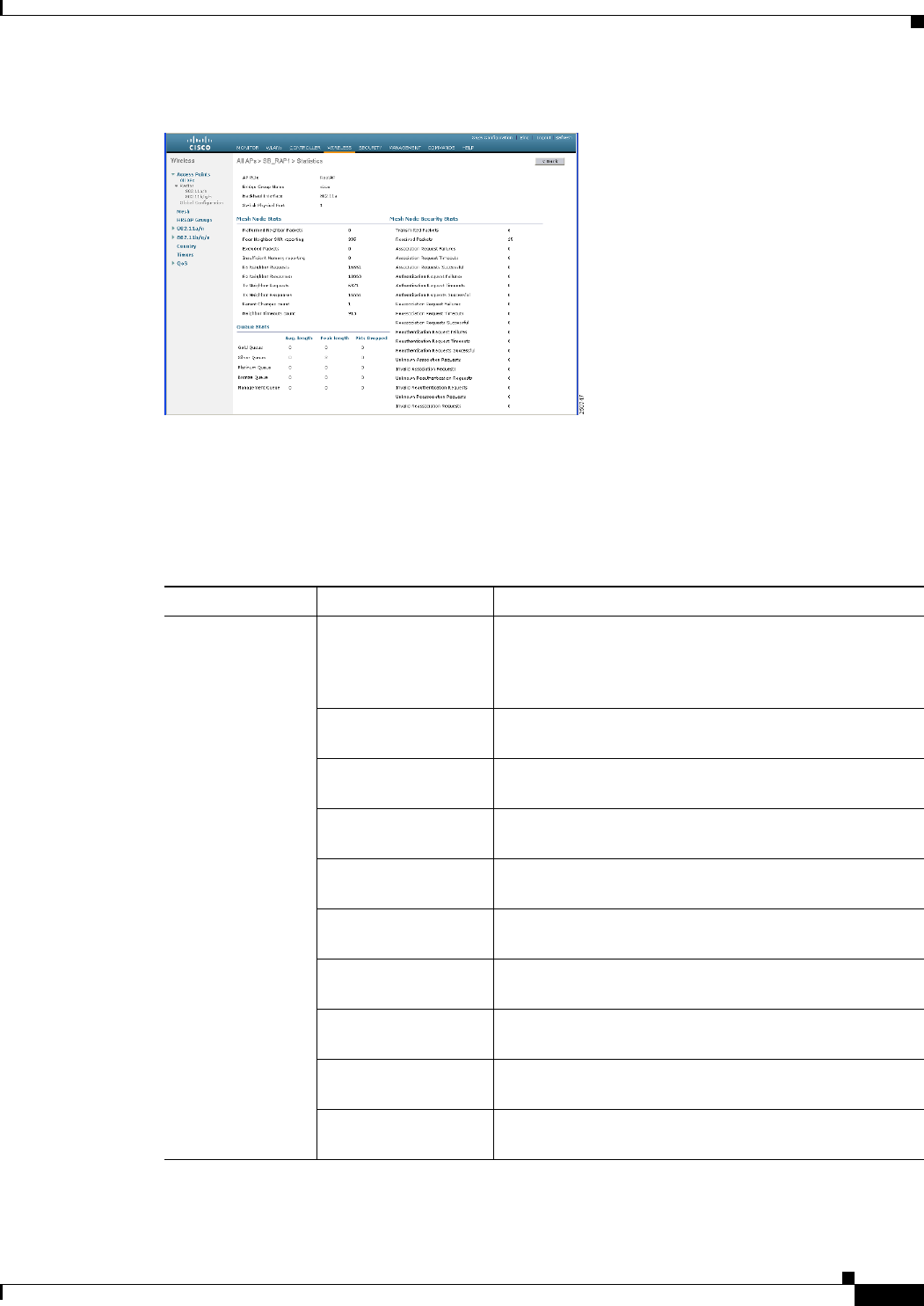
9-117
Cisco Wireless LAN Controller Configuration Guide
OL-21524-02
Chapter 9 Controlling Mesh Access Points
Viewing Mesh Statistics for a Mesh Access Point
Figure 9-70 All APs > Access Point Name > Statistics Page
This page shows the role of the mesh access point in the mesh network, the name of the bridge group to
which the mesh access point belongs, the backhaul interface on which the access point operates, and the
number of the physical switch port. It also displays a variety of mesh statistics for this mesh access point.
Table 9-17 describes each of the statistics.
Ta b l e 9-17 Mesh Access Point Statistics
Statistics Parameter Description
Mesh Node Stats Malformed Neighbor
Packets
The number of malformed packets received from the
neighbor. Examples of malformed packets include
malicious floods of traffic such as malformed or short
DNS packets and malformed DNS replies.
Poor Neighbor SNR
Reporting
The number of times the signal-to-noise ratio falls below
12 dB on the backhaul link.
Excluded Packets The number of packets received from excluded neighbor
mesh access points.
Insufficient Memory
Reporting
The number of insufficient memory conditions.
Rx Neighbor Requests The number of broadcast and unicast requests received
from the neighbor mesh access points.
Rx Neighbor
Responses
The number of responses received from the neighbor
mesh access points.
Tx Neighbor Requests The number of unicast and broadcast requests sent to the
neighbor mesh access points.
Tx Neighbor
Responses
The number of responses sent to the neighbor mesh
access points.
Parent Changes Count The number of times a mesh access point (child) moves
to another parent.
Neighbor Timeouts
Count
The number of neighbor timeouts.

9-118
Cisco Wireless LAN Controller Configuration Guide
OL-21524-02
Chapter 9 Controlling Mesh Access Points
Viewing Mesh Statistics for a Mesh Access Point
Queue Stats Gold Queue The average and peak number of packets waiting in the
gold (video) queue during the defined statistics time
interval.
Silver Queue The average and peak number of packets waiting in the
silver (best effort) queue during the defined statistics
time interval.
Platinum Queue The average and peak number of packets waiting in the
platinum (voice) queue during the defined statistics time
interval.
Bronze Queue The average and peak number of packets waiting in the
bronze (background) queue during the defined statistics
time interval.
Management Queue The average and peak number of packets waiting in the
management queue during the defined statistics time
interval.
Table 9-17 Mesh Access Point Statistics (continued)
Statistics Parameter Description

9-119
Cisco Wireless LAN Controller Configuration Guide
OL-21524-02
Chapter 9 Controlling Mesh Access Points
Viewing Mesh Statistics for a Mesh Access Point
Mesh Node
Security Stats
Transmitted Packets The number of packets transmitted during security
negotiations by the selected mesh access point.
Received Packets The number of packets received during security
negotiations by the selected mesh access point.
Association Request
Failures
The number of association request failures that occur
between the selected mesh access point and its parent.
Association Request
Timeouts
The number of association request timeouts that occur
between the selected mesh access point and its parent.
Association Requests
Successful
The number of successful association requests that occur
between the selected mesh access point and its parent.
Authentication
Request Failures
The number of failed authentication requests that occur
between the selected mesh access point and its parent.
Authentication
Request Timeouts
The number of authentication request timeouts that occur
between the selected mesh access point and its parent.
Authentication
Requests Successful
The number of successful authentication requests
between the selected mesh access point and its parent.
Reassociation Request
Failures
The number of failed reassociation requests between the
selected mesh access point and its parent.
Reassociation Request
Timeouts
The number of reassociation request timeouts between
the selected mesh access point and its parent.
Reassociation
Requests Successful
The number of successful reassociation requests between
the selected mesh access point and its parent.
Reauthentication
Request Failures
The number of failed reauthentication requests between
the selected mesh access point and its parent.
Reauthentication
Request Timeouts
The number of reauthentication request timeouts that
occur between the selected mesh access point and its
parent.
Reauthentication
Requests Successful
The number of successful reauthentication requests that
occur between the selected mesh access point and its
parent.
Unknown Association
Requests
The number of unknown association requests received by
the parent mesh access point from its child. The unknown
association requests often occur when a child is an
unknown neighbor mesh access point.
Invalid Association
Requests
The number of invalid association requests received by
the parent mesh access point from the selected child mesh
access point. This state may occur when the selected
child is a valid neighbor but is not in a state that allows
association.
Table 9-17 Mesh Access Point Statistics (continued)
Statistics Parameter Description

9-120
Cisco Wireless LAN Controller Configuration Guide
OL-21524-02
Chapter 9 Controlling Mesh Access Points
Viewing Mesh Statistics for a Mesh Access Point
Viewing Mesh Statistics for an Mesh Access Point Using the CLI
Use these commands to view mesh statistics for a specific mesh access point using the controller CLI:
• To view packet error statistics, a count of failures, timeouts, and successes with respect to
associations and authentications, and reassociations and reauthentications for a specific mesh access
point, enter this command:
show mesh security-stats AP_name
Information similar to the following appears:
AP MAC : 00:0B:85:5F:FA:F0
Packet/Error Statistics:
-----------------------------
x Packets 14, Rx Packets 19, Rx Error Packets 0
Parent-Side Statistics:
--------------------------
Unknown Association Requests 0
Invalid Association Requests 0
Unknown Re-Authentication Requests 0
Invalid Re-Authentication Requests 0
Unknown Re-Association Requests 0
Invalid Re-Association Requests 0
Unknown Re-Association Requests 0
Invalid Re-Association Requests 0
Child-Side Statistics:
--------------------------
Association Failures 0
Association Timeouts 0
Association Successes 0
Authentication Failures 0
Authentication Timeouts 0
Authentication Successes 0
Re-Association Failures 0
Mesh Node
Security Stats
(continued)
Unknown
Reauthentication
Requests
The number of unknown reauthentication requests
received by the parent mesh access point node from its
child. This state may occur when a child mesh access
point is an unknown neighbor.
Invalid
Reauthentication
Requests
The number of invalid reauthentication requests received
by the parent mesh access point from a child. This state
may occur when a child is a valid neighbor but is not in a
proper state for reauthentication.
Unknown
Reassociation
Requests
The number of unknown reassociation requests received
by the parent mesh access point from a child. This state
may occur when a child mesh access point is an unknown
neighbor.
Invalid Reassociation
Requests
The number of invalid reassociation requests received by
the parent mesh access point from a child. This state may
occur when a child is a valid neighbor but is not in a
proper state for reassociation.
Table 9-17 Mesh Access Point Statistics (continued)
Statistics Parameter Description

9-121
Cisco Wireless LAN Controller Configuration Guide
OL-21524-02
Chapter 9 Controlling Mesh Access Points
Viewing Neighbor Statistics for a Mesh Access Point
Re-Association Timeouts 0
Re-Association Successes 0
Re-Authentication Failures 0
Re-Authentication Timeouts 0
Re-Authentication Successes 0
• To view the number of packets in the queue by type, enter this command:
show mesh queue-stats AP_name
Information similar to the following appears:
Queue Type Overflows Peak length Average length
---------- --------- ----------- --------------
Silver 0 1 0.000
Gold 0 4 0.004
Platinum 0 4 0.001
Bronze 0 0 0.000
Management 0 0 0.000
Overflows—The total number of packets dropped due to queue overflow.
Peak Length—The peak number of packets waiting in the queue during the defined statistics time
interval.
Average Length—The average number of packets waiting in the queue during the defined statistics
time interval.
Viewing Neighbor Statistics for a Mesh Access Point
This section describes how to use the controller GUI or CLI to view neighbor statistics for a selected
mesh access point. It also describes how to run a link test between the selected mesh access point and
its parent.
Viewing Neighbor Statistics for a Mesh Access Point Using the GUI
To view neighbor statistics for a specific mesh access point using the controller GUI, follow these steps:
Step 1 Choose Wireless > Access Points > All APs to open the All APs page. (See Figure 9-71.)
Figure 9-71 All APs Page
Step 2 To view neighbor statistics for a specific mesh access point, hover the mouse over the blue drop-down
arrow for the desired mesh access point and choose Neighbor Information. The All APs > Access Point
Name > Neighbor Info page for the selected mesh access point appears (see Figure 9-72).
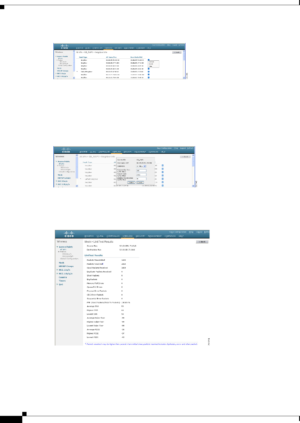
9-122
Cisco Wireless LAN Controller Configuration Guide
OL-21524-02
Chapter 9 Controlling Mesh Access Points
Viewing Neighbor Statistics for a Mesh Access Point
Figure 9-72 All APs > Access Point Name > Neighbor Info Page
This page lists the parent, children, and neighbors of the mesh access point. It provides each mesh access
point’s name and radio MAC address.
Step 3 To perform a link test between the mesh access point and its parent or children, follow these steps:
a. Hover the mouse over the blue drop-down arrow of the parent or desired child and choose LinkTest.
A pop-up window appears (see Figure 9-73).
Figure 9-73 Link Test Page
b. Click Submit to start the link test. The link test results appear on the Mesh > LinkTest Results page
(see Figure 9-74).
Figure 9-74 Mesh > LinkTest Results Page
c. Click Back to return to the All APs > Access Point Name > Neighbor Info page.
Step 4 To view the details for any of the mesh access points on this page, follow these steps:
a. Hover the mouse over the blue drop-down arrow for the desired mesh access point and choose
Details. The All APs > Access Point Name > Link Details > Neighbor Name page appears (see
Figure 9-75).
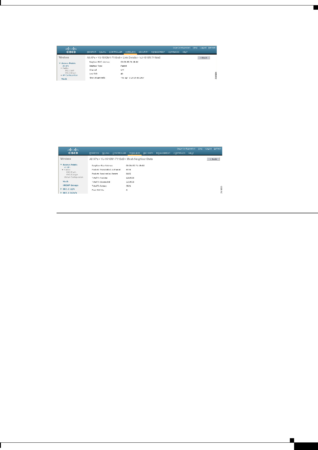
9-123
Cisco Wireless LAN Controller Configuration Guide
OL-21524-02
Chapter 9 Controlling Mesh Access Points
Viewing Neighbor Statistics for a Mesh Access Point
Figure 9-75 All APs > Access Point Name > Link Details > Neighbor Name page
b. Click Back to return to the All APs > Access Point Name > Neighbor Info page.
Step 5 To view statistics for any of the mesh access points on this page, follow these steps:
a. Hover the mouse over the blue drop-down arrow for the desired mesh access point and choose Stats.
The All APs > Access Point Name > Mesh Neighbor Stats page appears (see Figure 9-76).
Figure 9-76 All APs > Access Point Name > Mesh Neighbor Stats Page
b. Click Back to return to the All APs > Access Point Name > Neighbor Info page.
Viewing the Neighbor Statistics for a Mesh Access Point using the CLI
Use these commands to view neighbor statistics for a specific mesh access point using the controller CLI.
• To view the mesh neighbors for a specific mesh access point, enter this command:
show mesh neigh {detail | summary} AP_Name
Information similar to the following appears when you request a summary display:
AP Name/Radio Mac Channel Snr-Up Snr-Down Link-Snr Flags State
----------------- ------- ------ -------- -------- ------ -------
mesh-45-rap1 165 15 18 16 0x86b UPDATED NEIGH PARENT BEACON
00:0B:85:80:ED:D0 149 5 6 5 0x1a60 NEED UPDATE BEACON DEFAULT
00:17:94:FE:C3:5F 149 7 0 0 0x860 BEACON
• To view the channel and signal-to-noise ratio (SNR) details for a link between a mesh access point
and its neighbor, enter this command:
show mesh path AP_Name
Information similar to the following appears:
AP Name/Radio Mac Channel Snr-Up Snr-Down Link-Snr Flags State
----------------- ------- ------ -------- -------- ------ -------
mesh-45-rap1 165 15 18 16 0x86b UPDATED NEIGH PARENT BEACON
mesh-45-rap1 is a Root AP.
• To view the percentage of packet errors for packets transmitted by the neighbor mesh access point,
enter this command:
show mesh per-stats AP_Name

9-124
Cisco Wireless LAN Controller Configuration Guide
OL-21524-02
Chapter 9 Controlling Mesh Access Points
Converting Indoor Access Points to Mesh Access Points
Information similar to the following appears:
Neighbor MAC Address 00:0B:85:5F:FA:F0
Total Packets transmitted: 104833
Total Packets transmitted successfully: 104833
Total Packets retried for transmission: 33028
Neighbor MAC Address 00:0B:85:80:ED:D0
Total Packets transmitted: 0
Total Packets transmitted successfully: 0
Total Packets retried for transmission: 0
Neighbor MAC Address 00:17:94:FE:C3:5F
Total Packets transmitted: 0
Total Packets transmitted successfully: 0
Total Packets retried for transmission: 0
Packet error rate percentage = 1 – (number of successfully transmitted packets/number of total packets
transmitted).
Converting Indoor Access Points to Mesh Access Points
Before you can install and indoor access point into an indoor mesh deployment, follow these steps:
Step 1 Convert the autonomous access point (k9w7 image) to a lightweight access point.
For information about this process, see this URL:
http://cisco-images.cisco.com/en/US/docs/wireless/access_point/conversion/lwapp/upgrade/guide/lwap
note.html.
Step 2 Convert the lightweight access point to either a mesh access point (MAP) or root access point (RAP) as
follows:
Note Indoor mesh access points (1130 and 1240) can function as either a RAP or a MAP. By default, all are
configured as MAPs.
• To convert the access point to a mesh access point using the controller CLI, perform one of the
following:
–
To convert from a lightweight access point to a MAP, enter this command:
config ap mode bridge Cisco_AP
The mesh access point reloads.
–
To convert from a lightweight access point to a RAP, enter these CLI commands:
config ap mode bridge Cisco_AP
config ap role rootAP Cisco_AP
The mesh access point reloads and is configured to operate as a RAP.
• To convert the access point to a mesh access point using the GUI, follow these steps:
a. Choose Wireless and click on the AP Name link for the 1130 or 1240 indoor access point
you want to convert.
b. At the General Properties panel, choose Bridge from the AP Mode drop-down list.
The access point reboots.

9-125
Cisco Wireless LAN Controller Configuration Guide
OL-21524-02
Chapter 9 Controlling Mesh Access Points
Changing MAP and RAP Roles for Indoor Mesh Access Points
c. At the Mesh panel, choose either RootAP or MeshAP from the AP Role drop-down list.
d. Click Apply to commit your changes.
e. Click Save Configuration to save your changes.
Changing MAP and RAP Roles for Indoor Mesh Access Points
Cisco 1130 and 1240 series indoor mesh access points can function as either RAPs or MAPs.
Using the GUI to Change MAP and RAP Roles for Indoor Mesh Access Points
To change an indoor mesh access point from one role to another using the controller GUI, follow these
steps:
Step 1 Choose Wireless > Access Points > All APs to open the All APs page.
Step 2 Click the name of the 1130 or 1240 series access point that you want to change.
Step 3 Click the Mesh tab.
Step 4 From the AP Role drop-down list, choose MeshAP or RootAP to specify this access point as a MAP or
RAP, respectively.
Step 5 Click Apply to commit your changes. The access point reboots.
Step 6 Click Save Configuration to save your changes.
Note We recommend that you use a Fast Ethernet connection between the MAP and controller when
changing from a MAP to RAP.
Note After a RAP-to-MAP conversion, the MAP’s connection to the controller is a wireless backhaul
rather than a Fast Ethernet connection. You must ensure that the Fast Ethernet connection of the
RAP being converted is disconnected before the MAP starts up so that the MAP can join over
the air.
Note We recommend that your power source for MAPs is either a power supply or power injector. We
do not recommend that you use PoE as a power source for MAPs.
Using the CLI to Change MAP and RAP Roles for Indoor Mesh Access Points
To change an indoor mesh access point from one role to another using the controller CLI, follow these
steps:

9-126
Cisco Wireless LAN Controller Configuration Guide
OL-21524-02
Chapter 9 Controlling Mesh Access Points
Converting Indoor Mesh Access Points to Nonmesh Lightweight Access Points (1130AG, 1240AG)
Step 1 Change the role of an indoor access point from MAP to RAP or from RAP to MAP by entering this
command:
config ap role {rootAP | meshAP} Cisco_AP
The access point reboots after you change the role.
Step 2 Save your changes by entering this command:
save config
Converting Indoor Mesh Access Points to Nonmesh Lightweight
Access Points (1130AG, 1240AG)
The access point reboots after you enter the conversion commands in the controller CLI or perform the
steps on the controller or the Cisco WCS.
Note We recommend that you use a Fast Ethernet connection to the controller for the conversion from
a mesh (bridge) to nonmesh (local) access point. If the backhaul is a radio, after the conversion,
you must enable Ethernet and then reload the access image.
Note When a root access point is converted back to a lightweight access point, all of its subordinate
mesh access points lose connectivity to the controller. A mesh access point is unable to service
its clients until the mesh access point is able to connect to a different root access point in the
vicinity. Likewise, clients might connect to a different mesh access point in the vicinity to
maintain connectivity to the network.
• To convert an indoor mesh access point (MAP or RAP) to a nonmesh lightweight access point using
the controller CLI, enter this command.
config ap mode local Cisco_AP
The access point reloads.
• To convert an indoor mesh access point (MAP or RAP) to a nonmesh lightweight access point using
the GUI, follow these steps:
a. Choose Wireless and click on the AP Name link for the 1130 or 1240 indoor access point you
want to convert.
b. At the General Properties panel, choose Local from the AP Mode drop-down list.
c. Click Apply to apply changes.
d. Click Save Configuration to save your changes.
• To convert an indoor mesh access point (MAP or RAP) to a nonmesh lightweight access point using
Cisco WCS, follow these steps:
a. Choose Configure > Access Points and click on the AP Name link for the 1130 or 1240 indoor
access point you want to convert.
b. At the General Properties panel, choose Local as the AP Mode (left side).

9-127
Cisco Wireless LAN Controller Configuration Guide
OL-21524-02
Chapter 9 Controlling Mesh Access Points
Configuring Mesh Access Points to Operate with Cisco 3200 Series Mobile Access Routers
c. Click Save.
Configuring Mesh Access Points to Operate with Cisco 3200
Series Mobile Access Routers
Outdoor access points (1522, 1524PS) can interoperate with the Cisco 3200 Series Mobile Access
Router (MAR) on the public safety channel (4.9 GHz) as well as the 2.4-GHz access and 5-GHz
backhaul.
The Cisco 3200 creates an in-vehicle network in which devices such as PCs, surveillance cameras, digital
video recorders, printers, PDAs, and scanners can share wireless networks such as cellular or WLAN-
based services back to the main infrastructure. Data that is collected from in-vehicle deployments, such
as a police car can be integrated into the overall wireless infrastructure. For specific interoperability
details between series 1130, 1240, and 1520 mesh access points and series 3200 mobile access routers,
see Table 9-18.
Configuration Guidelines
Follow these guidelines to allow the 1522 or 1524PS mesh access point and Cisco MAR 3200 to
interoperate on the public safety network:
• Client access must be enabled on the backhaul (Mesh global parameter).
• Public Safety must be enabled globally on all mesh access points (MAPs) in the mesh network.
• Channel number assignments on the 1522 or 1524PS must match those on the Cisco 3200 radio
interfaces:
–
Channels 20 (4950 GHz) through 26 (4980 GHz) and sub-band channels 1 through 19 (5 and 10
MHz) are used for MAR interoperability. This configuration change is made on the controller.
No changes are made to the access point configuration.
–
Channel assignments are made only to the RAP. Updates to the MAP are propagated by the RAP.
The default channel width for MAR 3200s is 5 MHz. You must do one of the following:
• Change the channel width to 10 or 20 MHz to enable WGBs to associate with series 1520 mesh
access points.
• Change the channel on the 1522 or 1524PS to a channel in the 5-MHz (channels 1 to 10) or 10-MHz
band (channels 11 through 19) as follows:
Ta b l e 9-18 Mesh Access Points and MAR 3200 Interoperability
Mesh Access Point Model MAR Model
15221c32012, c32023, c32054
1524PS c3201, c3202
1130, 1240 configured as indoor mesh access
points with universal access
c3201, c3205
1. Universal access must be enabled on the 1522 if connecting to a MAR on the 802.11a radio or 4.9-GHz band.
2. Model c3201 is a MAR with a 802.11b/g radio (2.4 GHz).
3. Model c3202 is a MAR with a 4-9-GHz sub-band radio.
4. Model c3205 is a MAR with a 802.11a radio (5.8-GHz sub-band).
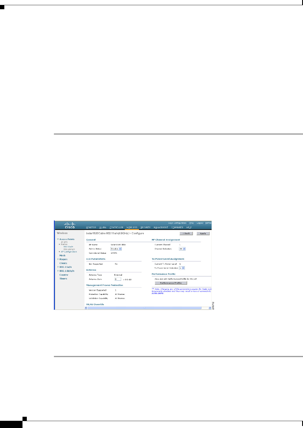
9-128
Cisco Wireless LAN Controller Configuration Guide
OL-21524-02
Chapter 9 Controlling Mesh Access Points
Configuring Mesh Access Points to Operate with Cisco 3200 Series Mobile Access Routers
–
When using the controller CLI, you must disable the 802.11a radio prior to configuring its
channels. You reenable the radio after the channels are configured.
–
When using the GUI, enabling and disabling the 802.11a radio for channel configuration is not
required.
–
Cisco MAR 3200s can scan channels within but not across the 5-, 10-, or 20-MHz bands.
Using the GUI to Enable Mesh Access Points to Operate with Cisco 3200 Series
Mobile Access Routers
To enable the 1522 and 1524PS mesh access points to associate to the Cisco 3200 series MAR using the
controller GUI, follow these steps:
Step 1 Enable the backhaul for client access by choosing Wireless > Mesh to open the Mesh page.
Step 2 Select the Backhaul Client Access check box to allow wireless client association over the 802.11a radio.
Step 3 Click Apply to commit your changes.
Step 4 When prompted to allow a reboot of all the mesh access points on the network, click OK.
Step 5 Choose Wireless > Access Points > Radios > 802.11a/n to open the 802.11a/n Radios page.
Step 6 Hover your cursor over the blue drop-down arrow for the appropriate RAP and choose Configure. The
802.11a/n (4.9 GHz) > Configure page appears (see Figure 9-77).
Figure 9-77 802.11 a/n (4.9GHz) > Configure Page
Step 7 Under the RF Channel Assignment section, choose the Custom option for Assignment Method and
select a channel between 1 and 26.
Step 8 Click Apply to commit your changes.
Step 9 Click Save Configuration to save your changes.

9-129
Cisco Wireless LAN Controller Configuration Guide
OL-21524-02
Chapter 9 Controlling Mesh Access Points
Configuring Mesh Access Points to Operate with Cisco 3200 Series Mobile Access Routers
Using the CLI to Enable Mesh Access Points to Operate with Cisco 3200 Series
Mobile Access Routers
To enable the 1522 and 1524PS mesh access points to associate to the Cisco 3200 series MAR using the
controller CLI, follow these steps:
Step 1 Enable client access mode on the 1522 and 1524PS mesh access points by entering this command:
config mesh client-access enable
Step 2 Enable public safety on a global basis by entering this command:
config mesh public-safety enable all
Step 3 Enable the public safety channels by entering these commands:
• For the 1522 access point, enter these commands:
config 802.11a disable Cisco_MAP
config 802.11a channel ap Cisco_MAP channel_number
config 802.11a enable Cisco_MAP
• For the 1524PS, enter these commands:
config 802.11–a49 disable Cisco_MAP
config 802.11–a49 channel ap Cisco_MAP channel_number
config 802.11–a49 enable Cisco_MAP
Note Enter the config 802.11–a58 enable Cisco_MAP command to enable a 5-GHz radio.
Note For both the 1522 and 1524PS mesh access points, valid values for the channel number is
1 through 26.
Step 4 Save your changes by entering this command:
save config
Step 5 Verify your configuration by entering these commands:
show mesh public-safety
show mesh client-access
show ap config 802.11a summary (for 1522 access points only)
show ap config 802.11–a49 summary (for 1524PS access points only)
Note Enter the show config 802.11-a58 summary command to view configuration details for a
5-GHz radio.

9-130
Cisco Wireless LAN Controller Configuration Guide
OL-21524-02
Chapter 9 Controlling Mesh Access Points
Configuring Mesh Access Points to Operate with Cisco 3200 Series Mobile Access Routers

CHAPTER
10-1
Cisco Wireless LAN Controller Configuration Guide
OL-21524-02
10
Managing Controller Software and
Configurations
This chapter describes how to manage configurations and software versions on the controllers. It
contains these sections:
• Upgrading the Controller Software, page 10-1
• Transferring Files to and from a Controller, page 10-15
• Saving Configurations, page 10-33
• Editing Configuration Files, page 10-33
• Clearing the Controller Configuration, page 10-34
• Erasing the Controller Configuration, page 10-34
• Resetting the Controller, page 10-35
Upgrading the Controller Software
When you upgrade the controller’s software, the software on the controller’s associated access points is
also automatically upgraded. When an access point is loading software, each of its LEDs blinks in
succession. Up to 10 access points can be concurrently upgraded from the controller.
Note The Cisco 5500 Series Controllers can download the 6.0 software to 100 access points simultaneously.
Caution Do not power down the controller or any access point during this process; otherwise, you might corrupt
the software image. Upgrading a controller with a large number of access points can take as long as 30
minutes, depending on the size of your network. However, with the increased number of concurrent
access point upgrades supported in software release 4.0.206.0 and later releases, the upgrade time should
be significantly reduced. The access points must remain powered, and the controller must not be reset
during this time.
Note In controller software release 5.2 or later releases, the WLAN override feature has been removed from
both the controller GUI and CLI. If your controller is configured for WLAN override and you upgrade
to controller software release 5.2 or later releases, the controller deletes the WLAN configuration and

10-2
Cisco Wireless LAN Controller Configuration Guide
OL-21524-02
Chapter 10 Managing Controller Software and Configurations
Upgrading the Controller Software
broadcasts all WLANs. You can specify that only certain WLANs be transmitted by configuring access
point groups. Each access point advertises only the enabled WLANs that belong to its access point
group.
Guidelines for Upgrading Controller Software
Follow these guidelines before upgrading your controller to software release 7.0.116.0:
• Make sure that you have a TFTP or FTP server available for the software upgrade. Follow these
guidelines when setting up a TFTP or FTP server:
–
Controller software release 6.0 is greater than 32 MB; you must make sure that your TFTP
server supports files that are larger than 32 MB. Some TFTP servers that support files of this
size are tftpd32 and the TFTP server is within WCS. If you attempt to download the 6.0
controller software and your TFTP server does not support files of this size, the following error
message appears: “TFTP failure while storing in flash.”
–
If you are upgrading through the service port, the TFTP or FTP server must be on the same
subnet as the service port because the service port is not routable, or you must create static
routes on the controller.
–
If you are upgrading through the distribution system network port, the TFTP or FTP server can
be on the same or a different subnet because the distribution system port is routable.
–
A third-party TFTP or FTP server cannot run on the same computer as WCS because the WCS
built-in TFTP or FTP server and the third-party TFTP or FTP server require the same
communication port.
• You can upgrade or downgrade the controller software only between certain releases. In some
instances, you must first install an intermediate release prior to upgrading to software release 6.0.
shows the upgrade path that you must follow prior to downloading software release 6.0.
Note The Cisco 5500 Series Controllers can run only controller software release 6.0 or later
releases.
Note When you upgrade the controller to an intermediate software release, wait until all of the
access points joined to the controller are upgraded to the intermediate release before you
install the 6.0 software. In large networks, it may take some time to download the software
on each access point.
• In software releases 6.0.186.0 and later releases, you can download the upgrade image to the
controller, and then download the image to the access points while the network is still up. New CLI
and controller GUI functionality allow you to specify the boot image for both devices and to reset
the access points when the controller resets. When both devices are up, the access points discover
and rejoin the controller. See the “Predownloading an Image to an Access Point” section on
page 10-11 for more information about predownloading images to access points.
• We recommend that you install the Cisco Unified Wireless Network Controller Boot Software
5.2.157.0 ER.aes file on all controller platforms. This file resolves CSCsm03461 and is necessary
to view the version information for ER.aes files in the output of the show sysinfo command. If you

10-3
Cisco Wireless LAN Controller Configuration Guide
OL-21524-02
Chapter 10 Managing Controller Software and Configurations
Upgrading the Controller Software
do not install this ER.aes file, your controller does not obtain the fix for this defect, and “N/A”
appears in the text box Recovery Image Version or Emergency Image Version text box in the output
of this command.
Note You cannot install the Cisco Unified Wireless Network Controller Boot Software
7.0.116.0ER.aes file on Cisco 5500 Controller platform.
Note The ER .aes files are independent from the controller software files. You can run any
controller software file with any ER.aes file. However, installing the latest boot software file
(5.2.157.0 ER.aes) ensures that the boot software modifications in all of the previous and
current boot software ER.aes files are installed.
Caution If you require a downgrade from one release to another, you may lose the configuration from your
current release. The workaround is to reload the previous controller configuration files saved on the
backup server or to reconfigure the controller.
Note Do not upgrade a controller using a wireless client as the TFTP or FTP server if the client is associated
to the same controller that is being upgraded. If you try upgrading a Wireless LAN Controller using an
associated client, the upgrade will fail. The controller will not attempt to contact the TFTP server to
download the image. The TFTP server can be located on a client that is not associated to the same
controller to which it is associated. This is applicable on all controller platforms.
Guidelines for Upgrading to Controller Software 6.0 in Mesh Networks
Caution Before upgrading your controller to software release 6.0 in a mesh network, you must comply with the
following rules.
Upgrade Compatibility Matrix
Table 10-1 outlines the upgrade compatibility of controller mesh and nonmesh releases and indicates the
intermediate software releases required as part of the upgrade path.
Software Upgrade Notes
• You can upgrade from all mesh releases to controller software release 6.0 without any configuration
file loss. See Table 10-1 for the available upgrade paths.
Note If you downgrade to a mesh release, you must then reconfigure the controller. We
recommend that you save the configuration from the mesh release before upgrading to
release 6.0 for the first time. You can reapply the configuration if you need to downgrade.

10-4
Cisco Wireless LAN Controller Configuration Guide
OL-21524-02
Chapter 10 Managing Controller Software and Configurations
Upgrading the Controller Software
• You cannot downgrade from controller software release 6.0 to a mesh release (4.1.190.5,
4.1.191.22M, or 4.1.192.xxM) without experiencing a configuration loss.
• Configuration files are in the binary state immediately after upgrade from a mesh release to
controller software release 6.0. After reset, the XML configuration file is selected.
• Do not edit XML files.
Ta b l e 10-1 Upgrade Compatibility Matrix for Controller Mesh and Non-Mesh Releases
Upgrade to
6.0
5.2
4.1.192.35M
4.1.191.24M
4.1.190.5
4.1.185.0
4.1.171.0
4.0.219.0
4.0.217.204
4.0.217.0
4.0.216.0
4.0.206.0
4.0.179.11
4.0.179.8
4.0.155.5
4.0.155.0
3.2.195.10
3.2.193.5
3.2.171.6
3.2.171.5
3.2.150.10
3.2.150.6
3.2.116.21
3.2.78.0
3.1.111.0
3.1.105.0
Upgrade from
4.1.192.35M Y Y
4.1.192.22M YYY
4.1.191.24M Y –
4.1.190.5 Y
1
Y –
4.1.185.0 Y Y
2
–
4.1.181.0 Y
2
Y
2
4.1.171.0 Y
2
Y
2
–
4.0.219.0 Y
2
Y
2
–
4.0.217.204 Y2Y2Y2Y2–
4.0.217.0 Y
2
Y
2
Y
2
Y
3
–
4.0.216.0 Y
2
Y
2
Y
2
Y3Y –
4.0.206.0 Y
2
Y
2
Y
2
Y3Y –
4.0.179.11 Y Y
4
–
4.0.179.8 Y Y
4
Y –
4.0.155.5 Y Y
4
YY–
4.0.155.0 Y Y
4
YYY–
3.2.195.10 Y Y
4
Y Y Y –
3.2.193.5 Y Y
4
YYY Y–

10-5
Cisco Wireless LAN Controller Configuration Guide
OL-21524-02
Chapter 10 Managing Controller Software and Configurations
Upgrading the Controller Software
Using the GUI to Upgrade Controller Software
To upgrade the controller software using the controller GUI, follow these steps:.
Note Do not install the 6.0 controller software file and the 5.2.157.0 ER.aes boot software file at the same
time. Install one file and reboot the controller and then install the other file and reboot the controller.
Step 1 Upload your controller configuration files to a server to back them up.
Note Cisco highly recommends that you back up your controller’s configuration files prior to
upgrading the controller software. See the “Uploading and Downloading Configuration Files”
section on page 10-27 for instructions.
3.2.171.6 Y Y
4
Y Y Y Y –
3.2.171.5 Y Y
4
Y Y Y Y Y –
3.2.150.10 Y Y
4
Y Y Y Y Y –
3.2.150.6 Y Y
4
Y Y Y Y Y Y –
3.2.116.21 Y Y
4
Y Y Y Y Y Y –
3.2.78.0 Y Y
4
Y Y Y Y Y Y Y –
3.1.111.0 Y Y Y Y Y –
3.1.105.0 Y Y Y Y Y Y –
3.1.59.24 Y Y Y Y Y Y Y
1. You can upgrade directly from software release 4.1.190.5 to 4.1.192.35M; however, upgrading to 4.1.191.24M before upgrading to 4.1.192.35M is
highly recommended.
2. CUSTOMERS WHO REQUIRE DYNAMIC FREQUENCY SELECTION (DFS) FUNCTIONALITY SHOULD NOT USE THIS RELEASE. This
release does not provide DFS functionality fixes found in release 4.0.217.204. Additionally, this release is not supported in ETSI-compliant countries
or Singapore.
3. Release 4.0.217.204 provides fixes for DFS on 1510 series access points. This functionality is needed only in countries where DFS rules apply.
4. An upgrade to 4.0.206.0 is not allowed in the following country codes when operating with the following access points: Australia (1505 and 1510), Brazil
(1505 and 1510), Hong Kong (1505 and 1510), India (1505 and 1510), Japan (1510), Korea (1505 and 1510), Mexico (1505 and 1510), New Zealand
(1505 and 1510), and Russia (1505 and 1510). The 1505 mesh access point is not supported in release 5.0 and later releases. The 1510 mesh access point
is supported only in mesh releases 4.1.190.5, 4.1.191.22M, and 4.1.192.xxM.
Table 10-1 Upgrade Compatibility Matrix for Controller Mesh and Non-Mesh Releases (continued)
Upgrade to
6.0
5.2
4.1.192.35M
4.1.191.24M
4.1.190.5
4.1.185.0
4.1.171.0
4.0.219.0
4.0.217.204
4.0.217.0
4.0.216.0
4.0.206.0
4.0.179.11
4.0.179.8
4.0.155.5
4.0.155.0
3.2.195.10
3.2.193.5
3.2.171.6
3.2.171.5
3.2.150.10
3.2.150.6
3.2.116.21
3.2.78.0
3.1.111.0
3.1.105.0

10-6
Cisco Wireless LAN Controller Configuration Guide
OL-21524-02
Chapter 10 Managing Controller Software and Configurations
Upgrading the Controller Software
Step 2 Obtain the 6.0 controller software and the Cisco Unified Wireless Network Controller Boot Software
5.2.157.0 ER.aes file from the Software Center on Cisco.com as follows:
a. Click this URL to go to the Software Center:
http://tools.cisco.com/support/downloads/go/Redirect.x?mdfid=278875243
b. Choose Wireless Software.
c. Choose Wireless LAN Controllers.
d. Choose Standalone Controllers or Integrated Controllers and Controller Modules.
e. Choose a controller series.
f. If necessary, choose a controller model.
g. If you chose Standalone Controllers in Step d., choose Wireless LAN Controller Software.
h. If you chose the Cisco Catalyst 6500 series / switch 7600 Series Wireless Services Module (WiSM)
in Step e., choose Wireless Services Modules (WiSM) Software.
i. Choose a controller software release. The software releases are labeled as follows to help you
determine which release to download:
• Early Deployment (ED)—These software releases provide new features, new hardware platform
support, and bug fixes.
• Maintenance Deployment (MD)—These software releases provide bug fixes and ongoing
software maintenance.
• Deferred (DF)—These software releases have been deferred. We recommend that you migrate
to an upgraded release.
j. Choose a software release number.
k. Click the filename (filename.aes).
l. Click Download.
m. Read Cisco’s End User Software License Agreement and then click Agree.
n. Save the file to your hard drive.
o. Repeat steps a. through n. to download the remaining file (either the 6.0 controller software or the
Cisco Unified Wireless Network Controller Boot Software 5.2.157.0 ER.aes file).
Step 3 Copy the controller software file (filename.aes) and the Cisco Unified Wireless Network Controller Boot
Software 5.2.157.0 ER.aes file to the default directory on your TFTP or FTP server.
Step 4 Disable the controller 802.11a and 802.11b/g networks.
Step 5 Disable any WLANs on the controller.
Step 6 Choose Commands > Download File to open the Download File to Controller page (see Figure 10-1).
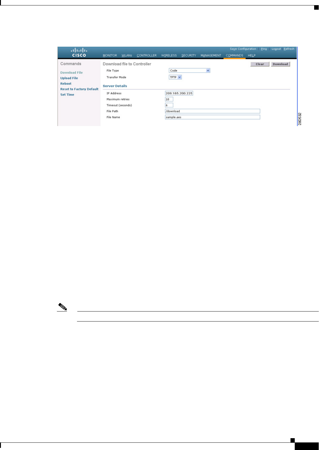
10-7
Cisco Wireless LAN Controller Configuration Guide
OL-21524-02
Chapter 10 Managing Controller Software and Configurations
Upgrading the Controller Software
Figure 10-1 Download File to Controller Page
Step 7 From the File Type drop-down list, choose Code.
Step 8 From the Transfer Mode drop-down list, choose TFTP or FTP.
Step 9 In the IP Address text box, enter the IP address of the TFTP or FTP server.
If you are using a TFTP server, the default values of 10 retries and 6 seconds for the Maximum Retries
and Timeout text boxes should work correctly without any adjustment. However, you can change these
values.
Step 10 Enter the maximum number of times that the TFTP server attempts to download the software in the
Maximum Retries text box and the amount of time (in seconds) that the TFTP server attempts to
download the software in the Timeout text box.
Step 11 In the File Path text box, enter the directory path of the software.
Step 12 In the File Name text box, enter the name of the controller software file (filename.aes).
Step 13 If you are using an FTP server, follow these steps:
a. In the Server Login Username text box, enter the username to log into the FTP server.
b. In the Server Login Password text box, enter the password to log into the FTP server.
c. In the Server Port Number text box, enter the port number on the FTP server through which the
download occurs. The default value is 21.
Step 14 Click Download to download the software to the controller. A message appears indicating the status of
the download.
Note You can schedule a reboot at a specified time. See Setting a Reboot Time, page 10-14.
Step 15 To install the remaining file (either the 6.0 controller software or the Cisco Unified Wireless Network
Controller Boot Software 5.2.157.0 ER.aes file).
Step 16 Reenable the WLANs.
Step 17 For Cisco WiSMs, reenable the controller port channel on the Catalyst switch.
Step 18 Reenable your 802.11a and 802.11b/g networks.
Step 19 (Optional) Reload your latest configuration file to the controller.
Step 20 Verify that the 6.0 controller software is installed on your controller by choosing Monitor on the
controller GUI and looking at the Software Version text box under Controller Summary.

10-8
Cisco Wireless LAN Controller Configuration Guide
OL-21524-02
Chapter 10 Managing Controller Software and Configurations
Upgrading the Controller Software
Step 21 Verify that the Cisco Unified Wireless Network Controller Boot Software 5.2.157.0 ER.aes file is
installed on your controller by choosing Monitor to open the Summary page and looking at the text box
Recovery Image Version or Emergency Image Version text box.
Note If a Cisco Unified Wireless Network Controller Boot Software ER.aes file is not installed, the
text box Recovery Image Version or Emergency Image Version text box shows “N/A.”
Using the CLI to Upgrade Controller Software
To upgrade the controller software using the controller CLI, follow these steps:
Note Do not install the 6.0 controller software file and the 5.2.157.0 ER.aes boot software file at the same
time. Install one file and reboot the controller; then install the other file and reboot the controller.
Step 1 Upload your controller configuration files to a server to back them up.
Note We highly recommend that you back up your controller’s configuration files prior to upgrading
the controller software. See the “Uploading and Downloading Configuration Files” section on
page 10-27 for instructions.
Step 2 Obtain the 6.0 controller software and the Cisco Unified Wireless Network Controller Boot Software
5.2.157.0 ER.aes file from the Software Center on Cisco.com as follows:
a. Click this URL to go to the Software Center:
http://tools.cisco.com/support/downloads/go/Redirect.x?mdfid=278875243
b. Choose Wireless Software.
c. Choose Wireless LAN Controllers.
d. Choose Standalone Controllers, Wireless Integrated Routers, or Wireless Integrated Switches.
e. Choose the name of a controller.
f. Choose Wireless LAN Controller Software.
g. Choose a controller software release.
h. Click the filename (filename.aes).
i. Click Download.
j. Read Cisco’s End User Software License Agreement and then click Agree.
k. Save the file to your hard drive.
l. Repeat steps a. to k. to download the remaining file (either the 6.0 controller software or the Cisco
Unified Wireless Network Controller Boot Software 5.2.157.0 ER.aes file).
Step 3 Copy the controller software file (filename.aes) and the Cisco Unified Wireless Network Controller Boot
Software 5.2.157.0 ER.aes file to the default directory on your TFTP or FTP server.
Step 4 Disable the controller 802.11a and 802.11b/g networks.

10-9
Cisco Wireless LAN Controller Configuration Guide
OL-21524-02
Chapter 10 Managing Controller Software and Configurations
Upgrading the Controller Software
Step 5 For Cisco WiSMs, shut down the controller port channel on the Catalyst switch to allow the controller
to reboot before the access points start downloading the software.
Step 6 Disable any WLANs on the controller (using the config wlan disable wlan_id command).
Step 7 Log into the controller CLI.
Step 8 Enter the ping server-ip-address command to verify that the controller can contact the TFTP or FTP
server.
Step 9 View current download settings by entering the transfer download start command. Answer n to the
prompt to view the current download settings.
Information similar to the following appears:
Mode........................................... TFTP
Data Type...................................... Code
TFTP Server IP................................. xxx.xxx.xxx.xxx
TFTP Packet Timeout............................... 6
TFTP Max Retries.................................. 10
TFTP Path...................................... <directory path>
TFTP Filename.................................. xxx.aes
This may take some time.
Are you sure you want to start? (y/N) n
Transfer Canceled
Step 10 Change the download settings, if necessary by entering these commands:
• transfer download mode {tftp | ftp}
• transfer download datatype code
• transfer download serverip server-ip-address
• transfer download filename filename
• transfer download path server-path-to-file
Note Pathnames on a TFTP or FTP server are relative to the server’s default or root directory. For
example, in the case of the Solarwinds TFTP server, the path is “/”.
If you are using a TFTP server, also enter these commands:
• transfer download tftpMaxRetries retries
• transfer download tftpPktTimeout timeout
Note The default values of 10 retries and a 6-second timeout should work correctly without any
adjustment. However, you can change these values. To do so, enter the maximum number of
times that the TFTP server attempts to download the software for the retries parameter and
the amount of time (in seconds) that the TFTP server attempts to download the software for
the timeout parameter.
If you are using an FTP server, also enter these commands:
• transfer download username username
• transfer download password password
• transfer download port port

10-10
Cisco Wireless LAN Controller Configuration Guide
OL-21524-02
Chapter 10 Managing Controller Software and Configurations
Upgrading the Controller Software
Note The default value for the port parameter is 21.
Step 11 View the current updated settings by entering the transfer download start command. Answer y to the
prompt to confirm the current download settings and start the software download.
Information similar to the following appears:
Mode........................................... TFTP
Data Type...................................... Code
TFTP Server IP.................................... xxx.xxx.xxx.xxx
TFTP Packet Timeout............................... 6
TFTP Max Retries............................... 10
TFTP Path...................................... <directory path>
TFTP Filename.................................. xxx.aes
Are you sure you want to start? (y/n) y
TFTP Code transfer starting.
TFTP receive complete... extracting components.
Writing new bootloader to flash.
Making backup copy of RTOS.
Writing new RTOS to flash.
Making backup copy of Code.
Writing new Code to flash.
TFTP File transfer operation completed successfully.
Please restart the switch (reset system) for update to complete.
Step 12 Save the code update to nonvolatile NVRAM and reboot the controller by entering this command:
reset system
The controller completes the bootup process.
Note You can also schedule a reboot at a specified time. See Setting a Reboot Time, page 10-14.
Step 13 To install the remaining file (either the 6.0 controller software or the Cisco Unified Wireless Network
Controller Boot Software 5.2.157.0 ER.aes file).
Step 14 Reenable the WLANs by entering this command:
config wlan enable wlan_id
Step 15 For Cisco WiSMs, re-enable the controller port channel on the Catalyst switch.
Step 16 Reenable your 802.11a and 802.11b/g networks.
Step 17 (Optional) Reload your latest configuration file to the controller.
Step 18 Verify that the 7.0 controller software is installed on your controller by entering the show sysinfo
command and look at the Product Version text box.
Step 19 Verify that the Cisco Unified Wireless Network Controller Boot Software 5.2.157.0 ER.aes file is
installed on your controller by entering the show sysinfo command on the controller CLI and looking at
the text box Recovery Image Version or Emergency Image Version text box.
Note If a Cisco Unified Wireless Network Controller Boot Software ER.aes file is not installed, the
text box Recovery Image Version or Emergency Image Version text box shows “N/A.”

10-11
Cisco Wireless LAN Controller Configuration Guide
OL-21524-02
Chapter 10 Managing Controller Software and Configurations
Upgrading the Controller Software
Predownloading an Image to an Access Point
To minimize a network outages, you can now download an upgrade image to the access point from the
controller without resetting the access point or losing network connectivity. Previously, you would
download an upgrade image to the controller and reset it, which causes the access point to go into
discovery mode. After the access point discovers the controller with the new image, the access point
downloads the new image, resets, goes into discovery mode, and rejoins the controller.
You can now download the upgrade image to the controller and then download the image to the access
point while the network is still up. You can also schedule a reboot of the controller and access points,
either after a specified amount of time or at a specific date and time. When both devices are up, the access
point discovers and rejoins the controller.
Note These access point models do not support predownloading of images: 1120, 1230, and 1310.
Access Point Predownload Process
The access point predownload feature works as below:
• The controller image is downloaded.
–
The downloaded image becomes the backup image on the controller. Change the current boot
image as the backup image using the config boot backup command. This ensures that if a
system failure occurs, the controller boots with the last working image of the controller.
–
User predownloads the upgraded image using the config ap image predownload primary all
command. The upgrade image gets downloaded as the backup up image on the access points.
This can be verified using the show ap image all command.
–
User manually changes the boot image to primary using config boot primary command and
reboot the controller for the upgrade image to get activated.
or
–
User issues scheduled reboot with swap keyword. For more information see Setting a Reboot
Time, page 10-14. Here the swap keyword has the following importance: The swapping
happens to the primary and backup images on access point, and the currently active image on
controller with the backup image.
–
When the controller reboots, the access points get disassociated and eventually they come up
with upgrade image. Once the controller responds to the discovery request sent by access points
with its discovery response packet, the access point sends a join request.
• The actual upgrade of the images occur. The following sequence of actions occur.
–
During boot time, the access point sends a join request.
–
Controller responds with the join response along with the image version the controller is
running.
–
The access point compares its running image with the running image on the controller. If the
versions match, the access point joins the controller.
–
If the versions do not match, the access point compares the version of the backup image and if
they match, the access point swaps the primary and backup images and reloads and
subsequently joins the controller.
–
If the primary image of the access point is same as that of the controllers’, the access point
reloads and joins the controller.

10-12
Cisco Wireless LAN Controller Configuration Guide
OL-21524-02
Chapter 10 Managing Controller Software and Configurations
Upgrading the Controller Software
–
If none of the above conditions are true, the access point sends a image data request to the
controller, downloads the latest image, reloads and joins the contoller.
Guidelines and Limitations for Predownloading Images
Follow these guidelines when you use image predownloading:
• The maximum number of concurrent predownloads is limited to half the number of concurrent
normal image downloads. This limitation allows new access points to join the controller during
image downloading.
If you reach the predownload limit, then the access points that cannot get an image sleep for a time
between 180 to 600 seconds and then reattempt the predownload.
• Before you enter the predownload command, you should change the active controller boot image to
the backup image. This step ensures that if the controller reboots for some reason, it comes back up
with the earlier running image, not the partially downloaded upgrade image.
• Access points with 16-MB total available memory (1130 and 1240 access points) may not have
enough free memory to download an upgrade image and may automatically delete crash info files,
radio files, and any backup images to free up space. However, this limitation does not affect the
predownload process because the predownload image replaces any backup image on the access
point.
• When the system time is changed by using the config time command, the time set for scheduled
reset will not be valid and the scheduled system reset will be canceled. You are given an option either
to cancel the scheduled reset before configuring the time or retain the scheduled reset and not
configure the time.
• All the primary, secondary, and tertiary controllers should run the same images as the primary and
backup images. That is, the primary image of all three controllers should be X and the secondary
image of all three controllers should be Y or the feature will not be effective.
• At the time of the reset, if any AP is downloading the controller image, the scheduled reset is
canceled. The following message appears with the reason why the scheduled reset was canceled:
%OSAPI-3-RESETSYSTEM_FAILED: osapi_task.c:4458 System will not reset as software is
being upgraded.
Using the GUI to Predownload an Image to an Access Point
Using the GUI, you can predownload an image to a specific access point or to all access points.
To predownload an image using the controller GUI, follow these steps:
Step 1 Obtain the upgrade image and copy the image to the controller by performing Step 1 through Step 14 in
the “Using the GUI to Upgrade Controller Software” section on page 10-5.
Step 2 Choose Wireless > Access Points > Global Configuration to open the Global Configuration page (see
Figure 10-2).
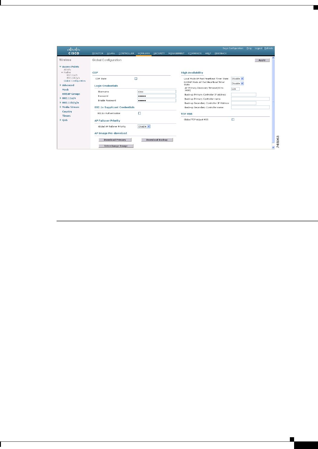
10-13
Cisco Wireless LAN Controller Configuration Guide
OL-21524-02
Chapter 10 Managing Controller Software and Configurations
Upgrading the Controller Software
Figure 10-2 Wireless > Access Points > Global Configuration Page
Step 3 Perform one of the following:
• To instruct all the access points to predownload a primary image from the controller, click
Download Primary under the AP Image Pre-download.
• To instruct all the access points to swap their primary and backup images, click Interchange Image.
• To download an image from the controller and store it as a backup image, click Download Backup.
Step 4 Click Apply to commit your changes.
Using the CLI to Predownload an Image to Access Points
Using the CLI, you can predownload an image to a specific access point or to all access points. The
process includes three steps:
1. Obtaining the upgrade image.
2. Specify access points that will receive the predownload image.
3. Set a reboot time for the controller and the access points.
Obtaining the Upgrade Image
To obtain the upgrade image and copy the image to the controller, follow Step 1 through Step 11 in the
“Using the CLI to Upgrade Controller Software” section on page 10-8.
Specifying Access Points for Predownload
Use one of these commands to specify access points for predownload:
• Specify access points for predownload by entering this command:
config ap image predownload {primary | backup} {ap_name | all}
The primary image is the new image; the backup image is the existing image. Access points always
boot with the primary image.
• Swap an access point’s primary and backup images by entering this command:

10-14
Cisco Wireless LAN Controller Configuration Guide
OL-21524-02
Chapter 10 Managing Controller Software and Configurations
Upgrading the Controller Software
config ap image swap {ap_name | all}
• Display detailed information on access points specified for predownload by entering this command:
show ap image {all | ap-name}
Information similar to the following appears:
Total number of APs.............................. 7
Number of APs
Initiated....................................... 4
Predownloading.................................. 0
Completed predownloading........................ 3
Not Supported................................... 0
Failed to Predownload........................... 0
AP Name Primary Image Backup Image Predownload Predownload Version Next Retry Time Retry
status Version Count
------------------ -------------- -------------- --------------- --------------
---------------- ------------
AP1140-1 7.0.56.0 6.0.183.38 Complete 6.0.183.38 NA NA
AP1140-2 7.0.56.0 6.0.183.58 Initiated 6.0.183.38 23:46:43 1
AP1130-2 7.0.56.0 6.0.183.38 Complete 6.0.183.38 NA NA
AP1130-3 7.0.56.0 6.0.183.58 Initiated 6.0.183.38 23:43:25 1
AP1130-4 7.0.56.0 6.0.183.38 Complete 6.0.183.38 NA NA
AP1130-5 7.0.56.0 6.0.183.58 Initiated 6.0.183.38 23:43:00 1
AP1130-6 7.0.56.0 6.0.183.58 Initiated 6.0.183.38 23:41:33 1
The output lists access points that are specified for predownloading and provides for each access point,
primary and secondary image versions, the version of the predownload image, the predownload retry
time (if necessary), and the number of predownload attempts. The output also includes the predownload
status for each device. The status of the access points is as follows:
• None—The access point is not scheduled for predownload.
• Predownloading—The access point is predownloading the image.
• Not supported—The access point (1120, 1230, and 1310) does not support predownloading.
• Initiated—The access point is waiting to get the predownload image because the concurrent
download limit has been reached.
• Failed—The access point has failed 64 predownload attempts.
• Complete—The access point has completed predownloading.
Setting a Reboot Time
Use one of these commands to schedule a reboot of the controller and access points:
• Specify the amount of time delay before the devices reboot by entering this command:
reset system in HH:MM:SS image {swap | no-swap} reset-aps [save-config]
Note The swap operand in the reset command will result in the swapping of the primary and
backup images on both the controller and the access point.
The controller sends a reset message to all joined access points, and then the controller resets.
• Specify a date and time for the devices to reboot by entering this command:
reset system at YYYY-MM-DD HH:MM:SS image {swap | no-swap} reset-aps [save-config]

10-15
Cisco Wireless LAN Controller Configuration Guide
OL-21524-02
Chapter 10 Managing Controller Software and Configurations
Transferring Files to and from a Controller
The controller sends a reset message to all joined access points, and then the controller resets.
Note The swap operand in the reset command will result in the swapping of the primary and
backup images on both the controller and the access point.
• Set up an SNMP trap message that announces the upcoming reset by entering this command:
reset system notify-time minutes
The controller sends the announcement trap the configured number of minutes before the reset.
• Cancel the scheduled reboot by entering this command:
reset system cancel
Note If you configure reset times and then use the config time command to change the system time on the
controller, the controller notifies you that any scheduled reset times will be canceled and must be
reconfigured after you set the system time.
Use the show reset command to display scheduled resets.
Information similar to the following appears:
System reset is scheduled for Apr 08 01:01:01 2010.
Current local time and date is Apr 07 02:57:44 2010.
A trap will be generated 10 minutes before each scheduled system reset.
Use 'reset system cancel' to cancel the reset.
Configuration will be saved before the system reset.
Transferring Files to and from a Controller
Controllers have built-in utilities for uploading and downloading various files. Follow the instructions
in these sections to import files using either the controller GUI or CLI:
• Downloading a Login Banner File, page 10-15
• Downloading Device Certificates, page 10-19
• Downloading CA Certificates, page 10-22
• Uploading PACs, page 10-25
• Uploading and Downloading Configuration Files, page 10-27
Downloading a Login Banner File
In controller software release 6.0 or later releases, you can download a login banner file using either the
GUI or the CLI. The login banner is the text that appears on the page before user authentication when
you access the controller GUI or CLI using Telnet, SSH, or a console port connection.
You save the login banner information as a text (*.txt) file. The text file cannot be larger than 1296
characters and cannot have more than 16 lines of text.

10-16
Cisco Wireless LAN Controller Configuration Guide
OL-21524-02
Chapter 10 Managing Controller Software and Configurations
Transferring Files to and from a Controller
Note The ASCII character set consists of printable and nonprintable characters. The login banner supports
only printable characters.
Here is an example of a login banner:
Welcome to the Cisco Wireless Controller!
Unauthorized access prohibited.
Contact sysadmin@corp.com for access.
Follow the instructions in this section to download a login banner to the controller through the GUI or
CLI. However, before you begin, make sure that you have a TFTP or FTP server available for the file
download. Follow these guidelines when setting up a TFTP or FTP server:
• If you are downloading through the service port, the TFTP or FTP server must be on the same subnet
as the service port because the service port is not routable, or you must create static routes on the
controller.
• If you are downloading through the distribution system network port, the TFTP or FTP server can
be on the same or a different subnet because the distribution system port is routable.
• A third-party TFTP or FTP server cannot run on the same computer as WCS because the WCS
built-in TFTP or FTP server and the third-party TFTP or FTP server require the same
communication port.
Note Clearing the controller configuration does not remove the login banner. See the “Using the GUI to Clear
the Login Banner” section on page 10-18 for information about clearing the login banner using the
controller GUI or CLI.
Note The controller can have only one login banner file. If you download another login banner file to the
controller, the first login banner file is overwritten.
Using the GUI to Download a Login Banner File
To download a login banner file to the controller using the controller GUI, follow these steps:
Step 1 Copy the login banner file to the default directory on your TFTP or FTP server.
Step 2 Choose Commands > Download File to open the Download File to Controller page (see Figure 10-3).
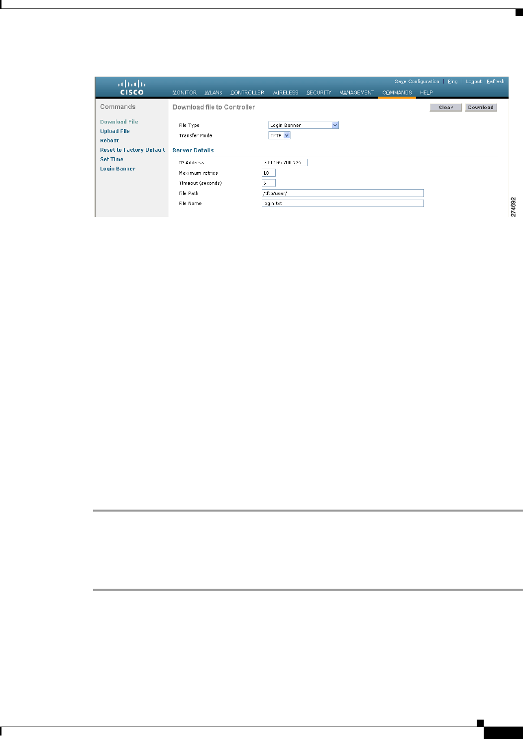
10-17
Cisco Wireless LAN Controller Configuration Guide
OL-21524-02
Chapter 10 Managing Controller Software and Configurations
Transferring Files to and from a Controller
Figure 10-3 Download File to Controller Page
Step 3 From the File Type drop-down list, choose Login Banner.
Step 4 From the Transfer Mode drop-down list, choose TFTP or FTP.
Step 5 In the IP Address text box, enter the IP address of the TFTP or FTP server.
If you are using a TFTP server, the default values of 10 retries and 6 seconds for the Maximum Retries
and Timeout text boxes should work correctly without any adjustment. However, you can change these
values.
Step 6 Enter the maximum number of times that the TFTP server attempts to download the certificate in the
Maximum Retries text box and the amount of time (in seconds) that the TFTP server attempts to
download the certificate in the Timeout text box.
Step 7 In the File Path text box, enter the directory path of the login banner file.
Step 8 In the File Name text box, enter the name of the login banner text (*.txt) file.
Step 9 If you are using an FTP server, follow these steps:
a. In the Server Login Username text box, enter the username to log into the FTP server.
b. In the Server Login Password text box, enter the password to log into the FTP server.
c. In the Server Port Number text box, enter the port number on the FTP server through which the
download occurs. The default value is 21.
Step 10 Click Download to download the login banner file to the controller. A message appears indicating the
status of the download.
Using the CLI to Download a Login Banner File
To download a login banner file to the controller using the controller CLI, follow these steps:
Step 1 Log into the controller CLI.
Step 2 Specify the transfer mode used to download the config file by entering this command:
transfer download mode {tftp | ftp}
Step 3 Download the controller login banner by entering this command:
transfer download datatype login-banner
Step 4 Specify the IP address of the TFTP or FTP server by entering this command:

10-18
Cisco Wireless LAN Controller Configuration Guide
OL-21524-02
Chapter 10 Managing Controller Software and Configurations
Transferring Files to and from a Controller
transfer download serverip server-ip-address
Step 5 Specify the name of the config file to be downloaded by entering this command:
transfer download path server-path-to-file
Step 6 Specify the directory path of the config file by entering this command:
transfer download filename filename.txt
Step 7 If you are using a TFTP server, enter these commands:
• transfer download tftpMaxRetries retries
• transfer download tftpPktTimeout timeout
Note The default values of 10 retries and a 6-second timeout should work correctly without any
adjustment. However, you can change these values. To do so, enter the maximum number of
times that the TFTP server attempts to download the software for the retries parameter and the
amount of time (in seconds) that the TFTP server attempts to download the software for the
timeout parameter.
Step 8 If you are using an FTP server, enter these commands:
• transfer download username username
• transfer download password password
• transfer download port port
Note The default value for the port parameter is 21.
Step 9 View the download settings by entering the transfer download start command. Answer y when
prompted to confirm the current settings and start the download process.
Information similar to the following appears:
Mode............................................. TFTP
Data Type........................................ Login Banner
TFTP Server IP................................... 10.10.10.10
TFTP Packet Timeout.............................. 6
TFTP Max Retries................................. 10
TFTP Path........................................ /
TFTP Filename.................................... banner.txt
This may take some time.
Are you sure you want to start? (y/N) y
TFTP Login Banner transfer starting.
TFTP receive complete... checking login banner.
Successfully installed new login banner file
Using the GUI to Clear the Login Banner
To clear the login banner from the controller using the controller GUI, follow these steps:
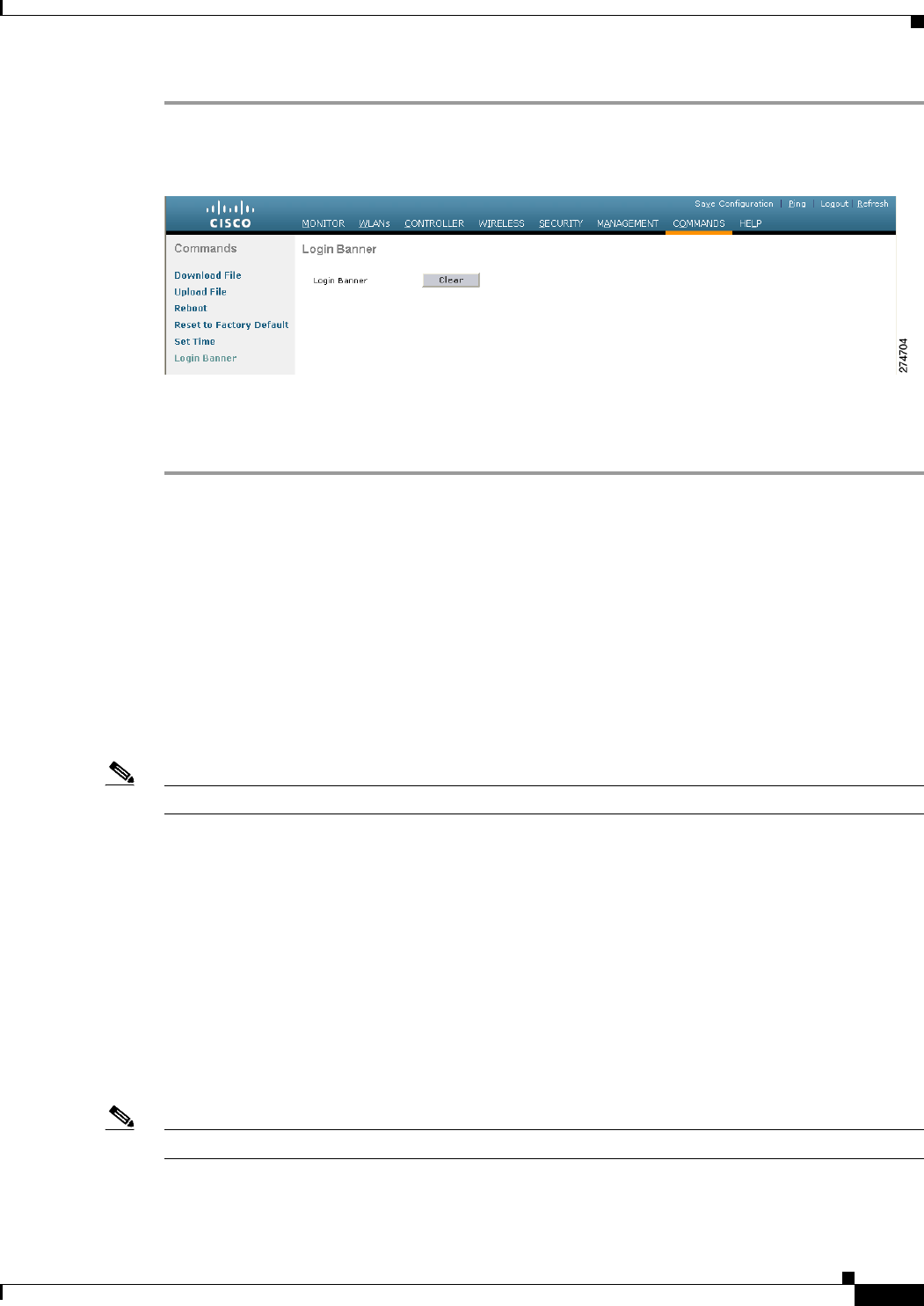
10-19
Cisco Wireless LAN Controller Configuration Guide
OL-21524-02
Chapter 10 Managing Controller Software and Configurations
Transferring Files to and from a Controller
Step 1 Choose Commands > Login Banner to open the Login Banner page (see Figure 10-4).
Figure 10-4 Login Banner Page
Step 2 Click Clear.
Step 3 When prompted, click OK to clear the banner.
To clear the login banner from the controller using the controller CLI, enter the clear login-banner
command.
Downloading Device Certificates
Each wireless device (controller, access point, and client) has its own device certificate. For example,
the controller is shipped with a Cisco-installed device certificate. This certificate is used by EAP-FAST
(when not using PACs), EAP-TLS, PEAP-GTC, and PEAP-MSCHAPv2 to authenticate wireless clients
during local EAP authentication. However, if you want to use your own vendor-specific device
certificate, it must be downloaded to the controller.
Note See the “Configuring Local EAP” section on page 6-42 for information on configuring local EAP.
Follow the instructions in this section to download a vendor-specific device certificate to the controller
through the GUI or CLI. However, before you begin, make sure you have a TFTP or FTP server available
for the certificate download. Follow these guidelines when setting up a TFTP or FTP server:
• If you are downloading through the service port, the TFTP or FTP server must be on the same subnet
as the service port because the service port is not routable, or you must create static routes on the
controller.
• If you are downloading through the distribution system network port, the TFTP or FTP server can
be on the same or a different subnet because the distribution system port is routable.
• A third-party TFTP or FTP server cannot run on the same computer as WCS because the WCS
built-in TFTP or FTP server and the third-party TFTP or FTP server require the same
communication port.
Note All certificates downloaded to the controller must be in PEM format.
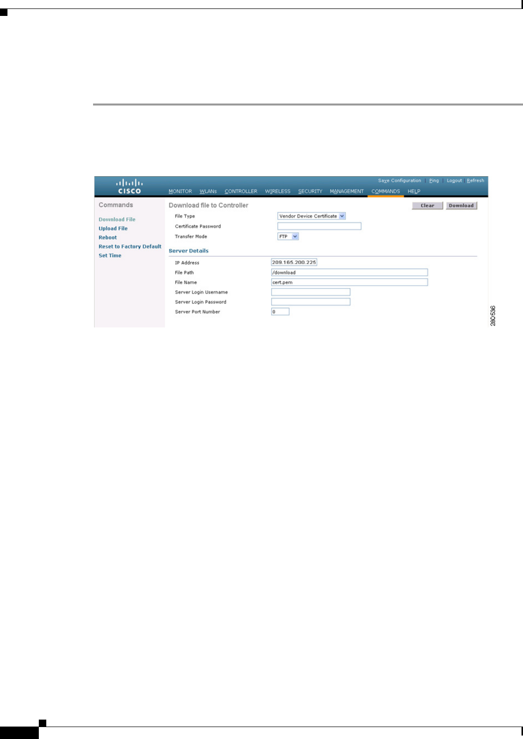
10-20
Cisco Wireless LAN Controller Configuration Guide
OL-21524-02
Chapter 10 Managing Controller Software and Configurations
Transferring Files to and from a Controller
Using the GUI to Download Device Certificates
To download a device certificate to the controller using the controller GUI, follow these steps:
Step 1 Copy the device certificate to the default directory on your TFTP or FTP server.
Step 2 Choose Commands > Download File to open the Download File to Controller page (see Figure 10-5).
Figure 10-5 Download File to Controller Page
Step 3 From the File Type drop-down list, choose Vendor Device Certificate.
Step 4 In the Certificate Password text box, enter the password that was used to protect the certificate.
Step 5 From the Transfer Mode drop-down list, choose TFTP or FTP.
Step 6 In the IP Address text box, enter the IP address of the TFTP or FTP server.
If you are using a TFTP server, the default values of 10 retries and 6 seconds for the Maximum Retries
and Timeout text boxes should work correctly without any adjustment. However, you can change these
values.
Step 7 Enter the maximum number of times that the TFTP server attempts to download the certificate in the
Maximum Retries text box and the amount of time (in seconds) that the TFTP server attempts to
download the certificate in the Timeout text box.
Step 8 In the File Path text box, enter the directory path of the certificate.
Step 9 In the File Name text box, enter the name of the certificate.
Step 10 If you are using an FTP server, follow these steps:
a. In the Server Login Username text box, enter the username to log into the FTP server.
b. In the Server Login Password text box, enter the password to log into the FTP server.
c. In the Server Port Number text box, enter the port number on the FTP server through which the
download occurs. The default value is 21.
Step 11 Click Download to download the device certificate to the controller. A message appears indicating the
status of the download.
Step 12 After the download is complete, choose Commands > Reboot > Reboot.
Step 13 If prompted to save your changes, click Save and Reboot.

10-21
Cisco Wireless LAN Controller Configuration Guide
OL-21524-02
Chapter 10 Managing Controller Software and Configurations
Transferring Files to and from a Controller
Step 14 Click OK to confirm your decision to reboot the controller.
Using the CLI to Download Device Certificates
To download a device certificate to the controller using the controller CLI, follow these steps:
Step 1 Log into the controller CLI.
Step 2 Specify the transfer mode used to download the config file by entering this command:
transfer download mode {tftp | ftp}
Step 3 Specify the type of the file to be downloaded by entering this command:
transfer download datatype eapdevcert
Step 4 Specify the certificate’s private key by entering this command:
transfer download certpassword password
Step 5 Specify the IP address of the TFTP or FTP server by entering this command:
transfer download serverip server-ip-address
Step 6 Specify the name of the config file to be downloaded by entering this command:
transfer download path server-path-to-file
Step 7 Specify the directory path of the config file by entering this command:
transfer download filename filename.pem
Step 8 If you are using a TFTP server, enter these commands:
• transfer download tftpMaxRetries retries
• transfer download tftpPktTimeout timeout
Note The default values of 10 retries and a 6-second timeout should work correctly without any
adjustment. However, you can change these values. To do so, enter the maximum number of
times that the TFTP server attempts to download the software for the retries parameter and the
amount of time (in seconds) that the TFTP server attempts to download the software for the
timeout parameter.
Step 9 If you are using an FTP server, enter these commands:
• transfer download username username
• transfer download password password
• transfer download port port
Note The default value for the port parameter is 21.
Step 10 View the updated settings by entering the transfer download start command. Answer y when prompted
to confirm the current settings and start the download process.
Information similar to the following appears:
Mode........................................... TFTP

10-22
Cisco Wireless LAN Controller Configuration Guide
OL-21524-02
Chapter 10 Managing Controller Software and Configurations
Transferring Files to and from a Controller
Data Type................................... Vendor Dev Cert
TFTP Server IP.............................. 10.10.10.4
TFTP Packet Timeout............................ 6
TFTP Max Retries............................... 10
TFTP Path................................... /tftpboot/username/
TFTP Filename............................... filename.pem
This may take some time.
Are you sure you want to start? (y/N) y
TFTP EAP Dev cert transfer starting.
Certificate installed.
Reboot the switch to use the new certificate.
Step 11 Reboot the controller by entering this command:
reset system
Downloading CA Certificates
Controllers and access points have a Certificate Authority (CA) certificate that is used to sign and
validate device certificates. The controller is shipped with a Cisco-installed CA certificate. This
certificate may be used by EAP-FAST (when not using PACs), EAP-TLS, PEAP-GTC, and
PEAP-MSCHAPv2 to authenticate wireless clients during local EAP authentication. However, if you
want to use your own vendor-specific CA certificate, it must be downloaded to the controller.
Note See the “Configuring Local EAP” section on page 6-42 for information on configuring local EAP.
Follow the instructions in this section to download CA certificates to the controller through the GUI or
CLI. However, before you begin, make sure that you have a TFTP or FTP server available for the
certificate download. Follow these guidelines when setting up a TFTP or FTP server:
• If you are downloading through the service port, the TFTP or FTP server must be on the same subnet
as the service port because the service port is not routable, or you must create static routes on the
controller.
• If you are downloading through the distribution system network port, the TFTP or FTP server can
be on the same or a different subnet because the distribution system port is routable.
• A third-party TFTP or FTP server cannot run on the same computer as WCS because the WCS
built-in TFTP or FTP server and the third-party TFTP or FTP server require the same
communication port.
Note All certificates downloaded to the controller must be in PEM format.
Using the GUI to Download CA Certificates
To download a CA certificate to the controller using the controller GUI, follow these steps:
Step 1 Copy the CA certificate to the default directory on your TFTP or FTP server.
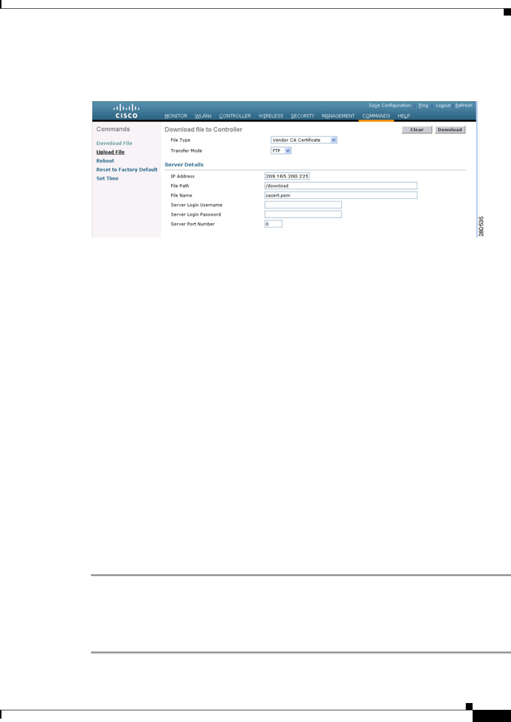
10-23
Cisco Wireless LAN Controller Configuration Guide
OL-21524-02
Chapter 10 Managing Controller Software and Configurations
Transferring Files to and from a Controller
Step 2 Choose Commands > Download File to open the Download File to Controller page (see Figure 10-6).
Figure 10-6 Download File to Controller Page
Step 3 From the File Type drop-down list, choose Vendor CA Certificate.
Step 4 From the Transfer Mode drop-down list, choose TFTP or FTP.
Step 5 In the IP Address text box, enter the IP address of the TFTP or FTP server.
If you are using a TFTP server, the default values of 10 retries and 6 seconds for the Maximum Retries
and Timeout text boxes should work correctly without any adjustment. However, you can change these
values.
Step 6 Enter the maximum number of times that the TFTP server attempts to download the certificate in the
Maximum Retries text box and the amount of time (in seconds) that the TFTP server attempts to
download the certificate in the Timeout text box.
Step 7 In the File Path text box, enter the directory path of the certificate.
Step 8 In the File Name text box, enter the name of the certificate.
Step 9 If you are using an FTP server, follow these steps:
a. In the Server Login Username text box, enter the username to log into the FTP server.
b. In the Server Login Password text box, enter the password to log into the FTP server.
c. In the Server Port Number text box, enter the port number on the FTP server through which the
download occurs. The default value is 21.
Step 10 Click Download to download the CA certificate to the controller. A message appears indicating the
status of the download.
Step 11 After the download is complete, choose Commands > Reboot > Reboot.
Step 12 If prompted to save your changes, click Save and Reboot.
Step 13 Click OK to confirm your decision to reboot the controller.
Using the CLI to Download CA Certificates
To download a CA certificate to the controller using the controller CLI, follow these steps:
Step 1 Log into the controller CLI.

10-24
Cisco Wireless LAN Controller Configuration Guide
OL-21524-02
Chapter 10 Managing Controller Software and Configurations
Transferring Files to and from a Controller
Step 2 Specify the transfer mode used to download the config file by entering this command:
transfer download mode {tftp | ftp}
Step 3 Specify the type of the file to be downloaded by entering this command:
transfer download datatype eapdevcert
Step 4 Specify the IP address of the TFTP or FTP server by entering this command:
transfer download serverip server-ip-address
Step 5 Specify the directory path of the config file by entering this command:
transfer download path server-path-to-file
Step 6 Specify the name of the config file to be downloaded by entering this command:
transfer download filename filename.pem
Step 7 If you are using a TFTP server, enter these commands:
• transfer download tftpMaxRetries retries
• transfer download tftpPktTimeout timeout
Note The default values of 10 retries and a 6-second timeout should work correctly without any
adjustment. However, you can change these values. To do so, enter the maximum number of
times that the TFTP server attempts to download the software for the retries parameter and the
amount of time (in seconds) that the TFTP server attempts to download the software for the
timeout parameter.
Step 8 If you are using an FTP server, enter these commands:
• transfer download username username
• transfer download password password
• transfer download port port
Note The default value for the port parameter is 21.
Step 9 View the updated settings by entering the transfer download start command. Answer y when prompted
to confirm the current settings and start the download process.
Information similar to the following appears:
Mode........................................... TFTP
Data Type................................... Vendor CA Cert
TFTP Server IP.............................. 10.10.10.4
TFTP Packet Timeout............................ 6
TFTP Max Retries............................... 10
TFTP Path................................... /tftpboot/username/
TFTP Filename............................... filename.pem
This may take some time.
Are you sure you want to start? (y/N) y
TFTP EAP CA cert transfer starting.
Certificate installed.
Reboot the switch to use the new certificate.
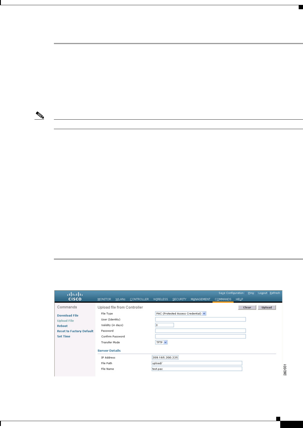
10-25
Cisco Wireless LAN Controller Configuration Guide
OL-21524-02
Chapter 10 Managing Controller Software and Configurations
Transferring Files to and from a Controller
Step 10 Reboot the controller by entering the reset system command.
Uploading PACs
Protected access credentials (PACs) are credentials that are either automatically or manually provisioned
and used to perform mutual authentication with a local EAP authentication server during EAP-FAST
authentication. When manual PAC provisioning is enabled, the PAC file is manually generated on the
controller.
Note See the “Configuring Local EAP” section on page 6-42 for information on configuring local EAP.
Follow the instructions in this section to generate and load PACs from the controller through the GUI or
CLI. However, before you begin, make sure you have a TFTP or FTP server available for the PAC upload.
Follow these guidelines when setting up a TFTP or FTP server:
• If you are uploading through the service port, the TFTP or FTP server must be on the same subnet
as the service port because the service port is not routable, or you must create static routes on the
controller.
• If you are uploading through the distribution system network port, the TFTP or FTP server can be
on the same or a different subnet because the distribution system port is routable.
• A third-party TFTP or FTP server cannot run on the same computer as WCS because the WCS
built-in TFTP or FTP server and the third-party TFTP or FTP server require the same
communication port.
Using the GUI to Upload PACs
To upload a PAC from the controller using the controller GUI, follow these steps:
Step 1 Choose Commands > Upload File to open the Upload File from Controller page (see Figure 10-7).
Figure 10-7 Upload File from Controller Page
Step 2 From the File Type drop-down list, choose PAC (Protected Access Credential).

10-26
Cisco Wireless LAN Controller Configuration Guide
OL-21524-02
Chapter 10 Managing Controller Software and Configurations
Transferring Files to and from a Controller
Step 3 In the User text box, enter the name of the user who will use the PAC.
Step 4 In the Validity text box, enter the number of days for the PAC to remain valid. The default setting is zero
(0).
Step 5 In the Password and Confirm Password text boxes, enter a password to protect the PAC.
Step 6 From the Transfer Mode drop-down list, choose TFTP or FTP.
Step 7 In the IP Address text box, enter the IP address of the TFTP or FTP server.
Step 8 In the File Path text box, enter the directory path of the PAC.
Step 9 In the File Name text box, enter the name of the PAC file. PAC files have a .pac extension.
Step 10 If you are using an FTP server, follow these steps:
a. In the Server Login Username text box, enter the username to log into the FTP server.
b. In the Server Login Password text box, enter the password to log into the FTP server.
c. In the Server Port Number text box, enter the port number on the FTP server through which the
upload occurs. The default value is 21.
Step 11 Click Upload to upload the PAC from the controller. A message appears indicating the status of the
upload.
Step 12 Follow the instructions for your wireless client to load the PAC on your client devices. Make sure to use
the password that you entered above.
Using the CLI to Upload PACs
To upload a PAC from the controller using the controller CLI, follow these steps:
Step 1 Log into the controller CLI.
Step 2 Specify the transfer mode used to upload the config file by entering this command:
transfer upload mode {tftp | ftp}
Step 3 Upload a Protected Access Credential (PAC) by entering this command:
transfer upload datatype pac
Step 4 Specify the identification of the user by entering this command:
transfer upload pac username validity password
Step 5 Specify the IP address of the TFTP or FTP server by entering this command:
transfer upload serverip server-ip-address
Step 6 Specify the directory path of the config file by entering this command:
transfer upload path server-path-to-file
Step 7 Specify the name of the config file to be uploaded by entering this command:
transfer upload filename manual.pac.
Step 8 If you are using an FTP server, enter these commands:
• transfer upload username username
• transfer upload password password
• transfer upload port port

10-27
Cisco Wireless LAN Controller Configuration Guide
OL-21524-02
Chapter 10 Managing Controller Software and Configurations
Transferring Files to and from a Controller
Note The default value for the port parameter is 21.
Step 9 View the updated settings by entering the transfer upload start command. Answer y when prompted to
confirm the current settings and start the upload process.
Information similar to the following appears:
Mode........................................... TFTP
TFTP Server IP................................. 10.10.10.4
TFTP Path...................................... /tftpboot/username/
TFTP Filename..................................... manual.pac
Data Type......................................... PAC
PAC User.......................................... username
PAC Validity...................................... 10 days
PAC Password................................... password
Are you sure you want to start? (y/N) y
PAC transfer starting.
File transfer operation completed successfully.
Step 10 Follow the instructions for your wireless client to load the PAC on your client devices. Make sure to use
the password that you entered above.
Uploading and Downloading Configuration Files
We recommend that you upload your controller’s configuration file to a server to back it up. If you lose
your configuration, you can then download the saved configuration to the controller.
Note Do not download a configuration file to your controller that was uploaded from a different controller
platform. For example, a Cisco 5500 Series Controller does not support the configuration file from a
Cisco 4400 Series or 2100 Series Controller.
In controller software release 4.2 or later releases, the controller’s bootup configuration file is stored in
an Extensible Markup Language (XML) format rather than in a binary format. Therefore, you cannot
download a binary configuration file onto a controller running software release 4.2 or later releases.
However, when you upgrade a controller from a previous software release to 4.2 or later releases, the
configuration file is migrated and converted to XML.
Follow these guidelines when working with configuration files:
• Any CLI with an invalid value is filtered out and set to default by the XML validation engine.
Validation occurs during bootup. A configuration may be rejected if the validation fails. A
configuration may fail if you have an invalid CLI. For example, if you have a CLI where you try to
configure a WLAN without adding appropriate commands to add the WLAN.
• A configuration may be rejected if the dependencies are not addressed. For example, if you try to
configure dependent parameters without using the add command. The XML validation may succeed
but the configuration download infrastructure will immediately reject the configuration with no
valadation errors.
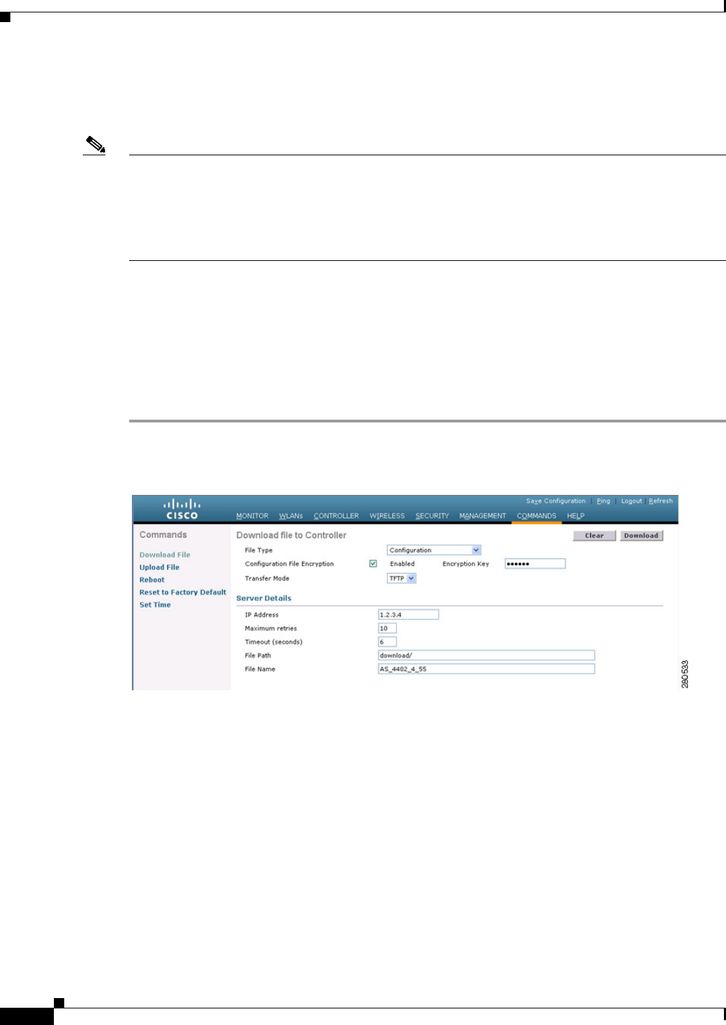
10-28
Cisco Wireless LAN Controller Configuration Guide
OL-21524-02
Chapter 10 Managing Controller Software and Configurations
Transferring Files to and from a Controller
• An invalid configuration can be verified by using the show invalid-config command. The show
invalid-config command reports the configuration that is rejected by the conftroller either as part of
download process or by XML validation infrastructure.
Note Controller software release 5.2 or later releases enable you to read and modify the configuration file. See
the “Editing Configuration Files” section on page 10-33 for details. Controller software releases prior to
5.2 do not allow configuration files to be modified. If you attempt to make changes to a 4.2, 5.0, or 5.1
configuration file and then download the file to a controller, the controller displays a cyclic redundancy
checksum (CRC) error while it is rebooting and returns the configuration parameters to their default
values.
Uploading Configuration Files
You can upload configuration files using either the GUI or the CLI.
Using the GUI to Upload Configuration Files
To upload a configuration file to a server using the controller GUI, follow these steps:
Step 1 Choose Commands > Upload File to open the Upload File from Controller page (see Figure 10-8).
Figure 10-8 Upload File from Controller Page
Step 2 From the File Type drop-down list, choose Configuration.
Step 3 Encrypt the configuration file by selecting the Configuration File Encryption check box and entering
the encryption key in the Encryption Key text box.
Step 4 From the Transfer Mode drop-down list, choose TFTP or FTP.
Step 5 In the IP Address text box, enter the IP address of the TFTP or FTP server.
Step 6 In the File Path text box, enter the directory path of the configuration file.
Step 7 In the File Name text box, enter the name of the configuration file.
Step 8 If you are using an FTP server, follow these steps:
a. In the Server Login Username text box, enter the username to log into the FTP server.
b. In the Server Login Password text box, enter the password to log into the FTP server.

10-29
Cisco Wireless LAN Controller Configuration Guide
OL-21524-02
Chapter 10 Managing Controller Software and Configurations
Transferring Files to and from a Controller
c. In the Server Port Number text box, enter the port number on the FTP server through which the
upload occurs. The default value is 21.
Step 9 Click Upload to upload the configuration file to the TFTP or FTP server. A message appears indicating
the status of the upload. If the upload fails, repeat this procedure and try again.
Using the CLI to Upload Configuration Files
To upload a configuration file to a server using the controller CLI, follow these steps:
Step 1 Specify the transfer mode used to upload the configuration file by entering this command:
transfer upload mode {tftp | ftp}
Step 2 Specify the type of file to be uploaded by entering this command:
transfer upload datatype config
Step 3 Encrypt the configuration file by entering these commands:
• transfer encrypt enable
• transfer encrypt set-key key, where key is the encryption key used to encrypt the file.
Step 4 Specify the IP address of the TFTP or FTP server by entering this command:
transfer upload serverip server-ip-address
Step 5 Specify the directory path of the configuration file by entering this command:
transfer upload path server-path-to-file
Step 6 Specify the name of the configuration file to be uploaded by entering this command:
transfer upload filename filename
Step 7 If you are using an FTP server, enter these commands to specify the username and password used to log
into the FTP server and the port number through which the upload occurs:
• transfer upload username username
• transfer upload password password
• transfer upload port port
Note The default value for the port parameter is 21.
Step 8 Initiate the upload process by entering this command:
transfer upload start
Step 9 When prompted to confirm the current settings, answer y.
Information similar to the following appears:
Mode............................................. TFTP
TFTP Server IP................................... 10.10.10.4
TFTP Path........................................ Config/
TFTP Filename.................................... AS_4402_4_2_55_8_Config.xml
Data Type........................................ Config File
Encryption....................................... Disabled
**************************************************
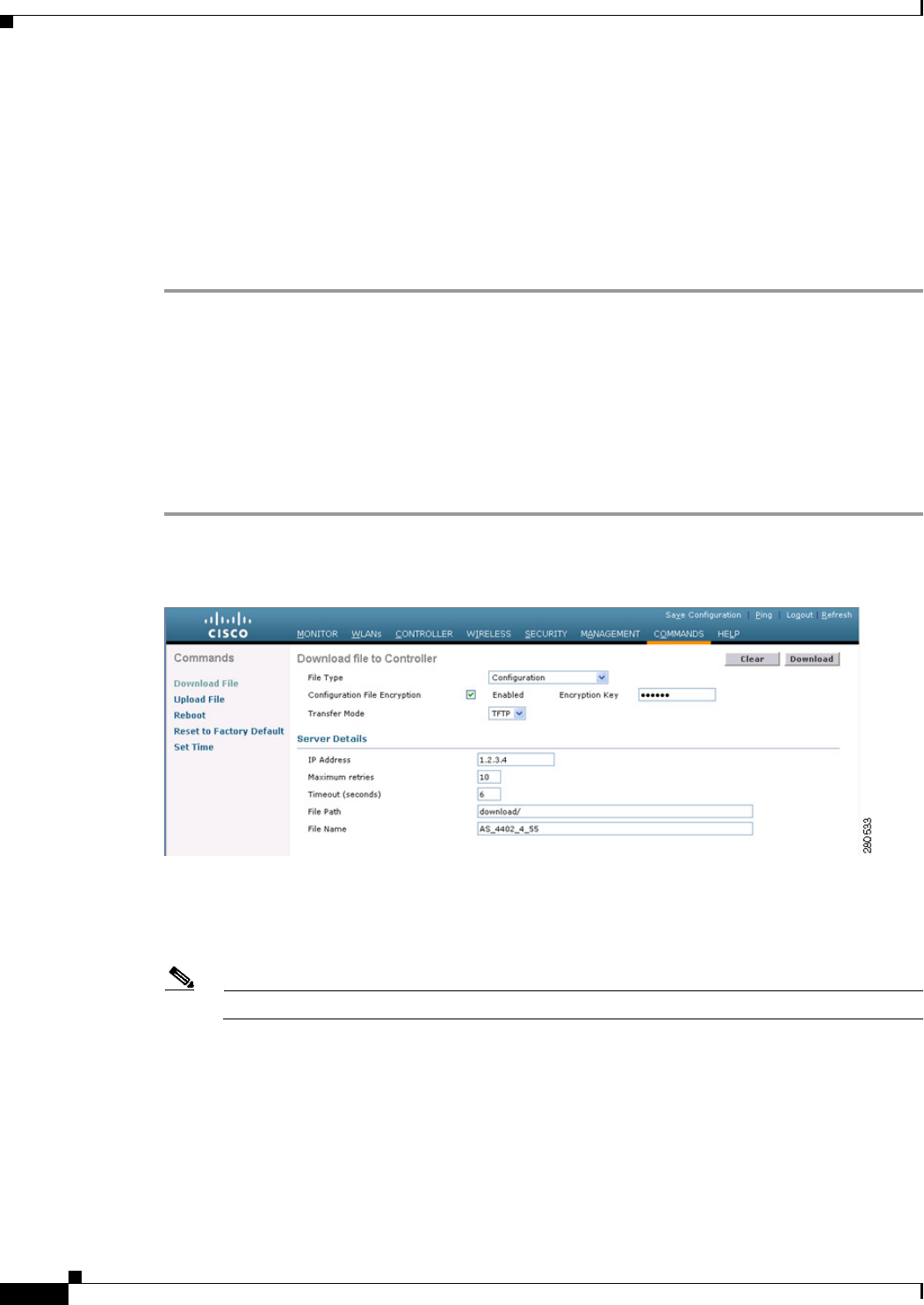
10-30
Cisco Wireless LAN Controller Configuration Guide
OL-21524-02
Chapter 10 Managing Controller Software and Configurations
Transferring Files to and from a Controller
*** WARNING: Config File Encryption Disabled ***
**************************************************
Are you sure you want to start? (y/N) y
File transfer operation completed successfully.
If the upload fails, repeat this procedure and try again.
Downloading Configuration Files
You can download configuration files using either the GUI or the CLI.
Using the GUI to Download Configuration Files
To download a configuration file to the controller using the controller GUI, follow these steps:
Step 1 Choose Commands > Download File to open the Download File to Controller page (see Figure 10-9).
Figure 10-9 Download File to Controller Page
Step 2 From the File Type drop-down list, choose Configuration.
Step 3 If the configuration file is encrypted, select the Configuration File Encryption check box and enter the
encryption key used to decrypt the file in the Encryption Key text box.
Note The key that you enter here should match the one entered during the upload process.
Step 4 From the Transfer Mode drop-down list, choose TFTP or FTP.
Step 5 In the IP Address text box, enter the IP address of the TFTP or FTP server.
If you are using a TFTP server, the default values of 10 retries and 6 seconds for the Maximum Retries
and Timeout text boxes should work correctly without any adjustment. However, you can change these
values.

10-31
Cisco Wireless LAN Controller Configuration Guide
OL-21524-02
Chapter 10 Managing Controller Software and Configurations
Transferring Files to and from a Controller
Step 6 Enter the maximum number of times that the TFTP server attempts to download the configuration file
in the Maximum Retries text box and the amount of time (in seconds) that the TFTP server attempts to
download the configuration file in the Timeout text box.
Step 7 In the File Path text box, enter the directory path of the configuration file.
Step 8 In the File Name text box, enter the name of the configuration file.
Step 9 If you are using an FTP server, follow these steps:
a. In the Server Login Username text box, enter the username to log into the FTP server.
b. In the Server Login Password text box, enter the password to log into the FTP server.
c. In the Server Port Number text box, enter the port number on the FTP server through which the
download occurs. The default value is 21.
Step 10 Click Download to download the file to the controller. A message appears indicating the status of the
download, and the controller reboots automatically. If the download fails, repeat this procedure and try
again.
Using the CLI to Download Configuration Files
To download a configuration file to the controller using the controller CLI, follow these steps:
Note The controller does not support incremental configuration downloads. The configuration file contains all
mandatory commands (all interface address commands, mgmtuser with read-write permission
commands, and interface port or LAG enable or disable commands) required to successfully complete
the download. For example, if you download only the config time ntp server index server_address
command as part of the configuration file, the download fails. Only the commands present in the
configuration file are applied to the controller, and any configuration in the controller prior to the
download is removed.
Step 1 Specify the transfer mode used to download the configuration file by entering this command:
transfer download mode {tftp | ftp}
Step 2 Specify the type of file to be downloaded by entering this command:
transfer download datatype config
Step 3 If the configuration file is encrypted, enter these commands:
• transfer encrypt enable
• transfer encrypt set-key key, where key is the encryption key used to decrypt the file
Note The key that you enter here should match the one entered during the upload process.
Step 4 Specify the IP address of the TFTP or FTP server by entering this command:
transfer download serverip server-ip-address
Step 5 Specify the directory path of the configuration file by entering this command:
transfer download path server-path-to-file
Step 6 Specify the name of the configuration file to be downloaded by entering this command:

10-32
Cisco Wireless LAN Controller Configuration Guide
OL-21524-02
Chapter 10 Managing Controller Software and Configurations
Transferring Files to and from a Controller
transfer download filename filename
Step 7 If you are using a TFTP server, enter these commands:
• transfer download tftpMaxRetries retries
• transfer download tftpPktTimeout timeout
Note The default values of 10 retries and a 6-second timeout should work correctly without any
adjustment. However, you can change these values. To do so, enter the maximum number of
times that the TFTP server attempts to download the software for the retries parameter and the
amount of time (in seconds) that the TFTP server attempts to download the software for the
timeout parameter.
Step 8 If you are using an FTP server, enter these commands to specify the username and password used to log
into the FTP server and the port number through which the download occurs:
• transfer download username username
• transfer download password password
• transfer download port port
Note The default value for the port parameter is 21.
Step 9 View the updated settings by entering this command:
transfer download start
Step 10 When prompted to confirm the current settings and start the download process, answer y.
Information similar to the following appears:
Mode............................................. TFTP
TFTP Server IP................................... 10.10.10.4
TFTP Path........................................ Config/
TFTP Filename.................................... AS_4402_4_2_55_8_Config.xml
Data Type........................................ Config File
Encryption....................................... Disabled
**************************************************
*** WARNING: Config File Encryption Disabled ***
**************************************************
Are you sure you want to start? (y/N) y
File transfer operation completed successfully.
If the download fails, repeat this procedure and try again.

10-33
Cisco Wireless LAN Controller Configuration Guide
OL-21524-02
Chapter 10 Managing Controller Software and Configurations
Saving Configurations
Saving Configurations
Controllers contain two kinds of memory: volatile RAM and NVRAM. At any time, you can save the
configuration changes from active volatile RAM to nonvolatile RAM (NVRAM) using one of these
commands:
• save config—Saves the configuration from volatile RAM to NVRAM without resetting the
controller.
• reset system—Prompts you to confirm that you want to save configuration changes before the
controller reboots.
• logout—Prompts you to confirm that you want to save configuration changes before you log out.
Editing Configuration Files
When you save the controller’s configuration, the controller stores it in XML format in flash memory.
Controller software release 5.2 or later releases enable you to easily read and modify the configuration
file by converting it to CLI format. When you upload the configuration file to a TFTP or FTP server, the
controller initiates the conversion from XML to CLI. You can then read or edit the configuration file in
a CLI format on the server. When you are finished, you download the file back to the controller, where
it is reconverted to an XML format and saved.
To edit the controller’s configuration file, follow these steps:
Step 1 Upload the configuration file to a TFTP or FTP server by performing one of the following:
• Upload the file using the controller GUI. Follow the instructions in the “Using the GUI to Upload
Configuration Files” section on page 10-28.
• Upload the file using the controller CLI. Follow the instructions in the “Using the CLI to Upload
Configuration Files” section on page 10-29.
Step 2 Read or edit the configuration file on the server. You can modify or delete existing CLI commands and
add new CLI commands to the file.
Note To edit the configuration file, you can use either Notepad or WordPad on Windows or the VI
editor on Linux.
Step 3 Save your changes to the configuration file on the server.
Step 4 Download the configuration file to the controller by performing one of the following:
• Download the file using the controller GUI. Follow the instructions in the “Using the GUI to
Download Configuration Files” section on page 10-30.
• Download the file using the controller CLI. Follow the instructions in the “Using the CLI to
Download Configuration Files” section on page 10-31.
The controller converts the configuration file to an XML format, saves it to flash memory, and then
reboots using the new configuration. CLI commands with known keywords and proper syntax are
converted to XML while improper CLI commands are ignored and saved to flash memory. Any CLI
commands that have invalid values are replaced with default values. To see any ignored commands or
invalid configuration values, enter this command:
show invalid-config

10-34
Cisco Wireless LAN Controller Configuration Guide
OL-21524-02
Chapter 10 Managing Controller Software and Configurations
Clearing the Controller Configuration
Note You cannot execute this command after the clear config or save config command.
Step 5 If the downloaded configuration contains a large number of invalid CLI commands, you might want to
upload the invalid configuration to the TFTP or FTP server for analysis. To do so, perform one of the
following:
• Upload the invalid configuration using the controller GUI. Follow the instructions in the “Using the
GUI to Upload Configuration Files” section on page 10-28 but choose Invalid Config from the File
Type drop-down list in Step 2 and skip Step 3.
• Upload the invalid configuration using the controller CLI. Follow the instructions in the “Using the
CLI to Upload Configuration Files” section on page 10-29 but enter the transfer upload datatype
invalid-config command in Step 2 and skip Step 3.
Step 6 The controller does not support the uploading and downloading of port configuration CLI commands. If
you want to configure the controller ports, enter these commands:
• config port linktrap {port | all} {enable | disable}—Enables or disables the up and down link traps
for a specific controller port or for all ports.
• config port adminmode {port | all} {enable | disable}—Enables or disables the administrative
mode for a specific controller port or for all ports.
Step 7 Save your changes by entering this command:
save config
Clearing the Controller Configuration
To clear the active configuration in NVRAM, follow these steps:
Step 1 Clear the configuration by entering this command:
clear config
Enter y at the confirmation prompt to confirm the action.
Step 2 Reboot the system by entering this command:
reset system
Enter n to reboot without saving configuration changes. When the controller reboots, the configuration
wizard starts automatically.
Step 3 Follow the instructions in the “Using the Configuration Wizard” section on page 2-1 to complete the
initial configuration.
Erasing the Controller Configuration
To reset the controller configuration to default, follow these steps:

10-35
Cisco Wireless LAN Controller Configuration Guide
OL-21524-02
Chapter 10 Managing Controller Software and Configurations
Resetting the Controller
Step 1 Reset the configuration by entering this command:
reset system
At the confirmation prompt, enter y to save configuration changes to NVRAM. The controller reboots.
Step 2 When you are prompted for a username, restore the factory-default settings by entering this command:
recover-config
The controller reboots and the configuration wizard starts automatically.
Step 3 Follow the instructions in the “Using the Configuration Wizard” section on page 2-1 to complete the
initial configuration.
Resetting the Controller
You can reset the controller and view the reboot process on the CLI console using one of the following
two methods:
• Turn the controller off and then turn it back on.
• On the CLI, enter reset system. At the confirmation prompt, enter y to save configuration changes
to NVRAM. The controller reboots.
When the controller reboots, the CLI console displays the following reboot information:
• Initializing the system.
• Verifying the hardware configuration.
• Loading microcode into memory.
• Verifying the operating system software load.
• Initializing with its stored configurations.
• Displaying the login prompt.

10-36
Cisco Wireless LAN Controller Configuration Guide
OL-21524-02
Chapter 10 Managing Controller Software and Configurations
Resetting the Controller

CHAPTER
11-1
Cisco Wireless LAN Controller Configuration Guide
OL-21524-02
11
Managing User Accounts
This chapter describes how to create and manage guest user accounts, how the web authentication
process works, and how to customize the web authentication login page. It contains these sections:
• Creating Guest User Accounts, page 11-1
• Obtaining a Web Authentication Certificate, page 11-6
• Web Authentication Process, page 11-9
• Choosing the Web Authentication Login Page, page 11-11
• Configuring Wired Guest Access, page 11-26
Creating Guest User Accounts
The controller can provide guest user access on WLANs. The first step in creating guest user accounts
is to create a lobby administrator account, also known as a lobby ambassador account. Once this account
has been created, a lobby ambassador can create and manage guest user accounts on the controller. The
lobby ambassador has limited configuration privileges and access only to the web pages used to manage
the guest accounts.
The lobby ambassador can specify the amount of time that the guest user accounts remain active. After
the specified time elapses, the guest user accounts expire automatically.
The local user database is limited to a maximum of 2048 entries, which is also the default value (on the
Security > AAA > General page). This database is shared by local management users (including lobby
ambassadors), local network users (including guest users), MAC filter entries, exclusion list entries, and
access point authorization list entries. Together they cannot exceed the configured maximum value.
Creating a Lobby Ambassador Account
You can create a lobby ambassador account on the controller through either the GUI or the CLI.
Using the GUI to Create a Lobby Ambassador Account
To create a lobby ambassador account using the controller GUI, follow these steps:
Step 1 Choose Management > Local Management Users to open the Local Management Users page (see
Figure 11-1).
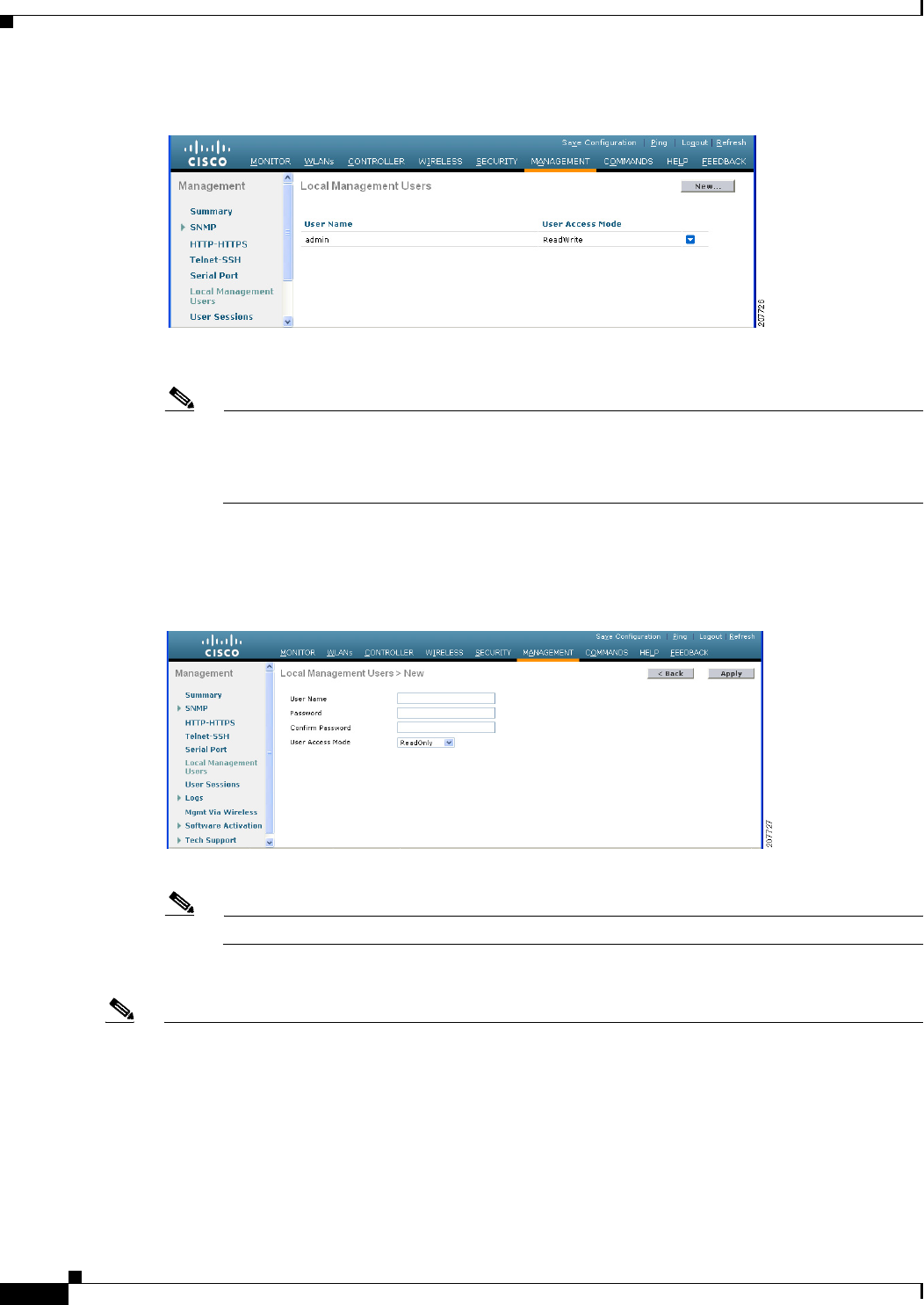
11-2
Cisco Wireless LAN Controller Configuration Guide
OL-21524-02
Chapter 11 Managing User Accounts
Creating Guest User Accounts
Figure 11-1 Local Management Users Page
This page lists the names and access privileges of the local management users.
Note If you want to delete any of the user accounts from the controller, hover your cursor over the
blue drop-down arrow and choose Remove. However, deleting the default administrative user
prohibits both GUI and CLI access to the controller. Therefore, you must create a user with
administrative privileges (ReadWrite) before you remove the default user.
Step 2 Click New to create a lobby ambassador account. The Local Management Users > New page appears
(see Figure 11-2).
Figure 11-2 Local Management Users > New Page
Step 3 In the User Name text box, enter a username for the lobby ambassador account.
Note Management usernames must be unique because they are stored in a single database.
Step 4 In the Password and Confirm Password text boxes, enter a password for the lobby ambassador account.
Note Passwords are case sensitive. The settings for the management User Details parameters depends on the
settings that you make in the Password Policy page. The following requirements are enforced on the
password
• The password should contain characters from at least three of the following classes: lowercase
letters, uppercase letters, digits, and special characters.
• No character in the password can be repeated more than three times consecutively.
• The password should not contain a management username or the reverse letters of a username.

11-3
Cisco Wireless LAN Controller Configuration Guide
OL-21524-02
Chapter 11 Managing User Accounts
Creating Guest User Accounts
• The password should not contain words like Cisco, oscic, admin, nimda, or any variant obtained by
changing the capitalization of letters by substituting 1, |, or ! or substituting 0 for o or substituting
$ for s.
Step 5 Choose LobbyAdmin from the User Access Mode drop-down list. This option enables the lobby
ambassador to create guest user accounts.
Note The ReadOnly option creates an account with read-only privileges, and the ReadWrite option
creates an administrative account with both read and write privileges.
Step 6 Click Apply to commit your changes. The new lobby ambassador account appears in the list of local
management users.
Step 7 Click Save Configuration to save your changes.
Using the CLI to Create a Lobby Ambassador Account
Use this command to create a lobby ambassador account using the controller CLI:
config mgmtuser add lobbyadmin_username lobbyadmin_pwd lobby-admin
Note Replacing lobby-admin with read-only creates an account with read-only privileges. Replacing
lobby-admin with read-write creates an administrative account with both read and write privileges.
Creating Guest User Accounts as a Lobby Ambassador
A lobby ambassador would follow these steps to create guest user accounts.
Note A lobby ambassador cannot access the controller CLI interface and therefore can create guest user
accounts only from the controller GUI.
Step 1 Log into the controller as the lobby ambassador, using the username and password specified in the
“Creating a Lobby Ambassador Account” section. The Lobby Ambassador Guest Management > Guest
Users List page appears (see Figure 11-3).
Figure 11-3 Lobby Ambassador Guest Management > Guest Users List Page
Step 2 Click New to create a guest user account. The Lobby Ambassador Guest Management > Guest Users
List > New page appears (see Figure 11-4).
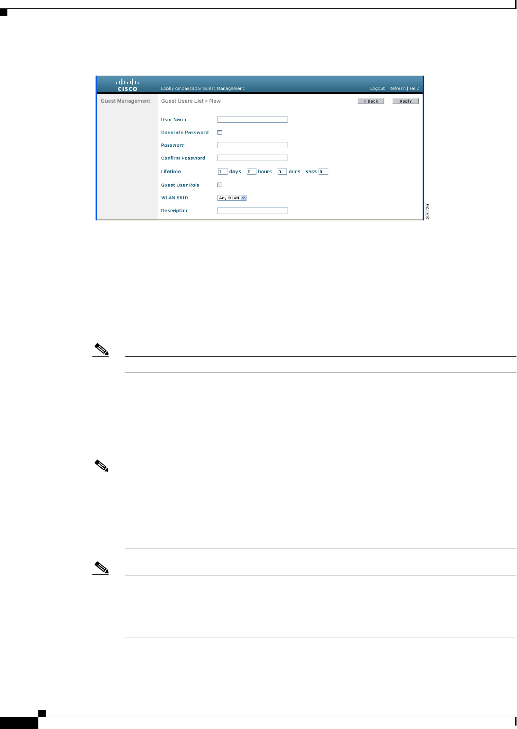
11-4
Cisco Wireless LAN Controller Configuration Guide
OL-21524-02
Chapter 11 Managing User Accounts
Creating Guest User Accounts
Figure 11-4 Lobby Ambassador Guest Management > Guest Users List > New Page
Step 3 In the User Name text box, enter a name for the guest user. You can enter up to 24 characters.
Step 4 Perform one of the following:
• If you want to generate an automatic password for this guest user, select the Generate Password
check box. The generated password is entered automatically in the Password and Confirm Password
text boxes.
• If you want to create a password for this guest user, leave the Generate Password check box
unselected and enter a password in both the Password and Confirm Password text boxes.
Note Passwords can contain up to 24 characters and are case sensitive.
Step 5 From the Lifetime drop-down lists, choose the amount of time (in days, hours, minutes, and seconds)
that this guest user account is to remain active. A value of zero (0) for all four text boxes creates a
permanent account.
Default: 1 day
Range: 5 minutes to 30 days
Note The smaller of this value or the session timeout for the guest WLAN, which is the WLAN on
which the guest account is created, takes precedence. For example, if a WLAN session timeout
is due to expire in 30 minutes but the guest account lifetime has 10 minutes remaining, the
account is deleted in 10 minutes upon guest account expiry. Similarly, if the WLAN session
timeout expires before the guest account lifetime, the client experiences a recurring session
timeout that requires reauthentication.
Note You can change a guest user account with a nonzero lifetime to another lifetime value at any time
while the account is active. However, to make a guest user account permanent using the
controller GUI, you must delete the account and create it again. If desired, you can use the config
netuser lifetime user_name 0 command to make a guest user account permanent without
deleting and recreating it.
Step 6 From the WLAN SSID drop-down list, choose the SSID that will be used by the guest user. The only
WLANs that are listed are those WLANs for which Layer 3 web authentication has been configured.
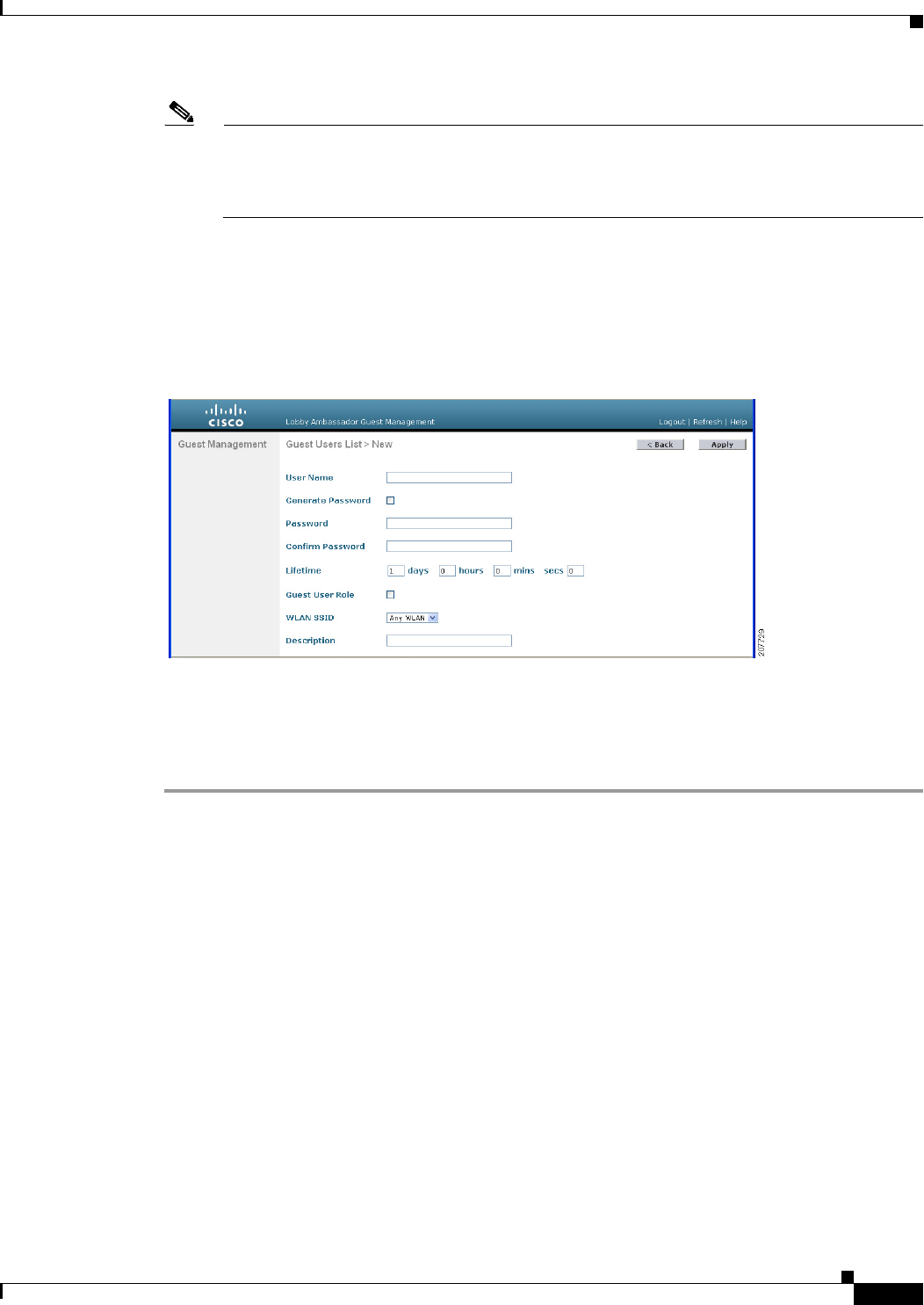
11-5
Cisco Wireless LAN Controller Configuration Guide
OL-21524-02
Chapter 11 Managing User Accounts
Creating Guest User Accounts
Note We recommend that you create a specific guest WLAN to prevent any potential conflicts. If a
guest account expires and it has a name conflict with an account on the RADIUS server and both
are on the same WLAN, the users associated with both accounts are disassociated before the
guest account is deleted.
Step 7 In the Description text box, enter a description of the guest user account. You can enter up to 32
characters.
Step 8 Click Apply to commit your changes. The new guest user account appears in the list of guest users on
the Guest Users List page (see Figure 11-5).
Figure 11-5 Lobby Ambassador Guest Management > Guest Users List Page
From this page, you can see all of the guest user accounts, their WLAN SSID, and their lifetime. You
can also edit or remove a guest user account. When you remove a guest user account, all of the clients
that are using the guest WLAN and are logged in using that account’s username are deleted.
Step 9 Repeat this procedure to create any additional guest user accounts.
Viewing Guest User Accounts
After a lobby ambassador has created guest user accounts, you can view them from the controller GUI
or CLI.
Using the GUI to View Guest Accounts
To view guest user accounts using the controller GUI, choose Security > AAA > Local Net Users. The
Local Net Users page appears (see Figure 11-6).

11-6
Cisco Wireless LAN Controller Configuration Guide
OL-21524-02
Chapter 11 Managing User Accounts
Obtaining a Web Authentication Certificate
Figure 11-6 Local Net Users Page
From this page, you can see all of the local net user accounts (including guest user accounts) and can
edit or remove them as desired. When you remove a guest user account, all of the clients that are using
the guest WLAN and are logged in using that account’s username are deleted.
Using the CLI to View Guest Accounts
To see all of the local net user accounts (including guest user accounts) using the controller CLI, enter
this command:
show netuser summary
Obtaining a Web Authentication Certificate
The controller’s operating system automatically generates a fully functional web authentication
certificate, so you do not need to do anything in order to use certificates with Layer 3 web authentication.
However, if desired, you can prompt the operating system to generate a new web authentication
certificate, or you can download an externally generated SSL certificate.
Support for Chained Certificate
In controller versions earlier than 5.1.151.0, web authentication certificates can be only device
certificates and should not contain the CA roots chained to the device certificate (no chained
certificates).
With controller version 5.1.151.0 and later, the controller allows for the device certificate to be
downloaded as a chained certificate (up to a level of 2) for web authentication. For more information
about chained certificates, see the Generate CSR for Third-Party Certificates and Download Chained
Certificates to the WLC document at
http://www.cisco.com/en/US/products/ps6366/products_configuration_example09186a0080a77592.sht
ml.
Using the GUI to Obtain a Web Authentication Certificate
To view the current web authentication certificate, generate a new certificate, or download an externally
generated certificate using the controller GUI, follow these steps:
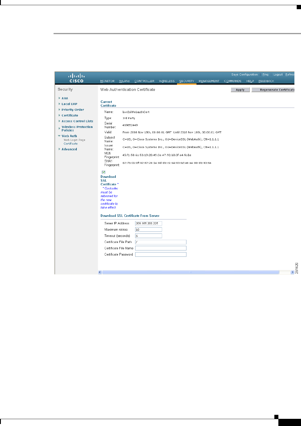
11-7
Cisco Wireless LAN Controller Configuration Guide
OL-21524-02
Chapter 11 Managing User Accounts
Obtaining a Web Authentication Certificate
Step 1 Choose Security > Web Auth > Certificate to open the Web Authentication Certificate page (see
Figure 11-7).
Figure 11-7 Web Authentication Certificate Page
This page shows the details of the current web authentication certificate.
Step 2 If you want to use a new operating system-generated web authentication certificate, follow these steps:
a. Click Regenerate Certificate. The operating system generates a new web authentication certificate,
and a successfully generated web authentication certificate message appears.
b. Reboot the controller to register the new certificate.
Step 3 If you prefer to use an externally generated web authentication certificate, follow these steps:
a. Verify that the controller can ping the TFTP server.
b. Select the Download SSL Certificate check box.
c. In the Server IP Address text box, enter the IP address of the TFTP server.
The default values of 10 retries and 6 seconds for the Maximum Retries and Timeout text boxes
should work correctly without any adjustment. However, you can change these values.
d. Enter the maximum number of times that each download can be attempted in the Maximum Retries
text box and the amount of time (in seconds) allowed for each download in the Timeout text box.

11-8
Cisco Wireless LAN Controller Configuration Guide
OL-21524-02
Chapter 11 Managing User Accounts
Obtaining a Web Authentication Certificate
e. In the Certificate File Path text box, enter the directory path of the certificate.
f. In the Certificate File Name text box, enter the name of the certificate (certname.pem).
g. In the Certificate Password text box, enter the password for the certificate.
h. Click Apply to commit your changes. The operating system downloads the new certificate from the
TFTP server.
i. Reboot the controller to register the new certificate.
Using the CLI to Obtain a Web Authentication Certificate
To see the current web authentication certificate, generate a new certificate, or download an externally
generated certificate using the controller CLI, follow these steps.
Step 1 See the current web authentication certificate by entering this command:
show certificate summary
Information similar to the following appears:
Web Administration Certificate................... Locally Generated
Web Authentication Certificate................... Locally Generated
Certificate compatibility mode:............... off
Step 2 If you want the operating system to generate a new web authentication certificate, follow these steps:
a. To generate the new certificate, enter this command:
config certificate generate webauth
b. To reboot the controller to register the new certificate, enter this command:
reset system
Step 3 If you prefer to use an externally generated web authentication certificate, follow these steps:
Note We recommend that the Common Name (CN) of the externally generated web authentication
certificate be 1.1.1.1 (or the equivalent virtual interface IP address) in order for the client’s
browser to match the domains of the web authentication URL and the web authentication
certificate.
a. Specify the name, path, and type of certificate to be downloaded by entering these commands:
transfer download mode tftp
transfer download datatype webauthcert
transfer download serverip server_ip_address
transfer download path server_path_to_file
transfer download filename certname.pem
transfer download certpassword password
transfer download tftpMaxRetries retries
transfer download tftpPktTimeout timeout
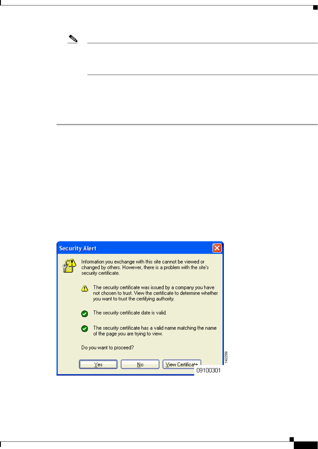
11-9
Cisco Wireless LAN Controller Configuration Guide
OL-21524-02
Chapter 11 Managing User Accounts
Web Authentication Process
Note The default values of 10 retries and a 6-second timeout should work correctly without any
adjustment. However, you can change these values. To do so, enter the maximum number of
times that each download can be attempted for the retries parameter and the amount of time
(in seconds) allowed for each download for the timeout parameter.
b. Start the download process by entering this command:
transfer download start
c. Reboot the controller to register the new certificate by entering this command:
reset system
Web Authentication Process
Web authentication is a Layer 3 security feature that causes the controller to not allow IP traffic (except
DHCP-related packets) from a particular client until that client has correctly supplied a valid username
and password. When you use web authentication to authenticate clients, you must define a username and
password for each client. When the clients attempt to join the wireless LAN, their users must enter the
username and password when prompted by a login page.
When web authentication is enabled (under Layer 3 Security), users might receive a web-browser
security alert the first time that they attempt to access a URL. Figure 11-8 shows a typical security alert.
Figure 11-8 Typical Web-Browser Security Alert
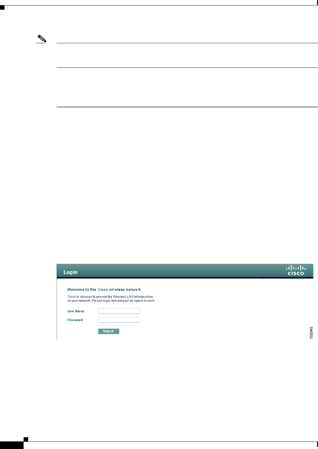
11-10
Cisco Wireless LAN Controller Configuration Guide
OL-21524-02
Chapter 11 Managing User Accounts
Web Authentication Process
Note When clients connect to a WebAuth SSID with preauthorization ACL configured to allow VPN users,
the clients will get disconnected from the SSID every few minutes. Webauth SSIDs must not connect
without authenticating on the web page.
After the user clicks Yes to proceed (or if the client’s browser does not display a security alert), the web
authentication system redirects the client to a login page (see Figure 11-9).
To prevent the security alert from appearing, follow these steps:
Step 1 Click View Certificate on the Security Alert page.
Step 2 Click Install Certificate.
Step 3 When the Certificate Import Wizard appears, click Next.
Step 4 Choose Place all certificates in the following store and click Browse.
Step 5 At the bottom of the Select Certificate Store page, select the Show Physical Stores check box.
Step 6 Expand the Trusted Root Certification Authorities folder and choose Local Computer.
Step 7 Click OK.
Step 8 Click Next > Finish.
Step 9 When the “The import was successful” message appears, click OK.
d. Because the issuer text box is blank on the controller self-signed certificate, open Internet Explorer,
choose Tools > Internet Options > Advanced, unselect the Warn about Invalid Site Certificates
check box under Security, and click OK.
Step 10 Reboot the PC. On the next web authentication attempt, the login page appears. Figure 11-9 shows the
default web authentication login window.
Figure 11-9 Default Web Authentication Login Page
The default login page contains a Cisco logo and Cisco-specific text. You can choose to have the web
authentication system display one of the following:
• The default login page
• A modified version of the default login page
• A customized login page that you configure on an external web server
• A customized login page that you download to the controller
The “Choosing the Web Authentication Login Page” section on page 11-11 provides instructions for
choosing how the web authentication login page appears.
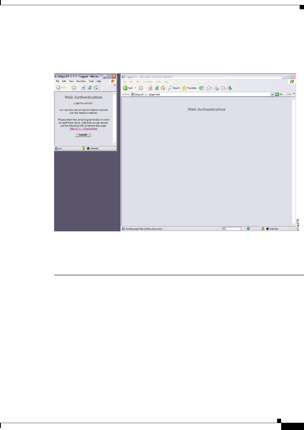
11-11
Cisco Wireless LAN Controller Configuration Guide
OL-21524-02
Chapter 11 Managing User Accounts
Choosing the Web Authentication Login Page
When the user enters a valid username and password on the web authentication login page and clicks
Submit, the web authentication system displays a successful login page and redirects the authenticated
client to the requested URL. Figure 11-10 shows a typical successful login page.
Figure 11-10 Successful Login Page
The default successful login page contains a pointer to a virtual gateway address URL:
https://1.1.1.1/logout.html. The IP address that you set for the controller virtual interface serves as the
redirect address for the login page (see Chapter 3, “Configuring Ports and Interfaces,” for more
information on the virtual interface).
Choosing the Web Authentication Login Page
This section provides instructions for specifying the content and appearance of the web authentication
login page. Follow the instructions in one of these sections to choose the web authentication login page
using the controller GUI or CLI:
• Choosing the Default Web Authentication Login Page, page 11-12
• Creating a Customized Web Authentication Login Page, page 11-16
• Using a Customized Web Authentication Login Page from an External Web Server, page 11-19
• Downloading a Customized Web Authentication Login Page, page 11-20
• Assigning Login, Login Failure, and Logout Pages per WLAN, page 11-24
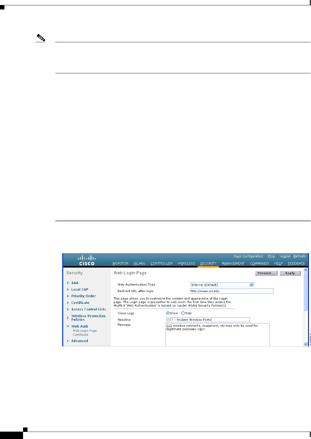
11-12
Cisco Wireless LAN Controller Configuration Guide
OL-21524-02
Chapter 11 Managing User Accounts
Choosing the Web Authentication Login Page
Note If you do not want users to connect to a web page using a browser that is configured with SSLv2 only,
you can disable SSLv2 for web authentication by entering the config network secureweb cipher-option
sslv2 disable command. If you enter this command, users must use a browser that is configured to use
a more secure protocol such as SSLv3 or later releases. The default value is enabled.
Choosing the Default Web Authentication Login Page
To use the default web authentication login page as is (see Figure 11-9) or with a few modifications,
follow the instructions in the GUI or CLI procedure in this section.
If you are using a custom web-auth bundle that is served by the internal controller web server, the page
should not contain more than 5 elements (including HTML, CSS, and Images). This is because the
internal controller web server implements a DoS protection mechanism that limits each client to open a
maximum of 5 (five) concurrent TCP connections depending on the load. Some browsers may try to open
more than 5 TCP sessions at the same time (For example Firefox 4) if the page contains more elements
and this may result in the page loading slowly depending on how the browser handles the DoS protection.
If you have a complex custom web authentication module, it is recommended that you use an external
web-auth config on the controller, where the full login page is hosted at an external web server.
Using the GUI to Choose the Default Web Authentication Login Page
To choose the default web authentication login page using the controller GUI, follow these steps:
Step 1 Choose Security > Web Auth > Web Login Page to open the Web Login page (see Figure 11-11).
Figure 11-11 Web Login Page
Step 2 From the Web Authentication Type drop-down list, choose Internal (Default).
Step 3 If you want to use the default web authentication login page as is, go to Step 8. If you want to modify
the default login page, go to Step 4.
Step 4 If you want to hide the Cisco logo that appears in the top right corner of the default page, choose the
Cisco Logo Hide option. Otherwise, click the Show option.
Step 5 If you want the user to be directed to a particular URL (such as the URL for your company) after login,
enter the desired URL in the Redirect URL After Login text box. You can enter up to 254 characters.

11-13
Cisco Wireless LAN Controller Configuration Guide
OL-21524-02
Chapter 11 Managing User Accounts
Choosing the Web Authentication Login Page
Note The controller supports web authentication redirects only to HTTP (HTTP over TCP) servers. It
does not support web authentication redirects to HTTPS (HTTP over SSL) servers.
Step 6 If you want to create your own headline on the login page, enter the desired text in the Headline text box.
You can enter up to 127 characters. The default headline is “Welcome to the Cisco wireless network.”
Step 7 If you want to create your own message on the login page, enter the desired text in the Message text box.
You can enter up to 2047 characters. The default message is “Cisco is pleased to provide the Wireless
LAN infrastructure for your network. Please login and put your air space to work.”
Step 8 Click Apply to commit your changes.
Step 9 Click Preview to view the web authentication login page.
Step 10 If you are satisfied with the content and appearance of the login page, click Save Configuration to save
your changes. Otherwise, repeat any of the previous steps as necessary to achieve your desired results.
Using the CLI to Choose the Default Web Authentication Login Page
To choose the default web authentication login page using the controller CLI, follow these steps:
Step 1 Specify the default web authentication type by entering this command:
config custom-web webauth_type internal
Step 2 If you want to use the default web authentication login page as is, go to Step 7. If you want to modify
the default login page, go to Step 3.
Step 3 To show or hide the Cisco logo that appears in the top right corner of the default login page, enter this
command:
config custom-web weblogo {enable | disable}
Step 4 If you want the user to be directed to a particular URL (such as the URL for your company) after login,
enter this command:
config custom-web redirecturl url
You can enter up to 130 characters for the URL. To change the redirect back to the default setting, enter
the clear redirecturl command.
Note The controller supports web authentication redirects only to HTTP (HTTP over TCP) servers. It
does not support web authentication redirects to HTTPS (HTTP over SSL) servers.
Step 5 If you want to create your own headline on the login page, enter this command:
config custom-web webtitle title
You can enter up to 130 characters. The default headline is “Welcome to the Cisco wireless network.”
To reset the headline to the default setting, enter the clear webtitle command.
Step 6 If you want to create your own message on the login page, enter this command:
config custom-web webmessage message

11-14
Cisco Wireless LAN Controller Configuration Guide
OL-21524-02
Chapter 11 Managing User Accounts
Choosing the Web Authentication Login Page
You can enter up to 130 characters. The default message is “Cisco is pleased to provide the Wireless
LAN infrastructure for your network. Please login and put your air space to work.” To reset the message
to the default setting, enter the clear webmessage command.
Step 7 Enter the save config command to save your settings.
Step 8 Import your own logo into the web authentication login page as follows:
a. Make sure that you have a Trivial File Transfer Protocol (TFTP) server available for the file
download. Follow these guidelines when setting up a TFTP server:
–
If you are downloading through the service port, the TFTP server must be on the same subnet
as the service port because the service port is not routable, or you must create static routes on
the controller.
–
If you are downloading through the distribution system network port, the TFTP server can be
on the same or a different subnet because the distribution system port is routable.
–
A third-party TFTP server cannot run on the same computer as the Cisco WCS because the WCS
built-in TFTP server and the third-party TFTP server require the same communication port.
b. Ensure that the controller can contact the TFTP server by entering this command:
ping ip-address
c. Copy the logo file (in .jpg, .gif, or .png format) to the default directory on your TFTP server. The
maximum file size is 30 kilobits. For an optimal fit, the logo should be approximately 180 pixels
wide and 360 pixels high.
d. Specify the download mode by entering this command:
transfer download mode tftp
e. Specify the type of file to be downloaded by entering this command:
transfer download datatype image
f. Specify the IP address of the TFTP server by entering this command:
transfer download serverip tftp-server-ip-address
Note Some TFTP servers require only a forward slash (/) as the TFTP server IP address, and
the TFTP server automatically determines the path to the correct directory.
g. Specify the download path by entering this command:
transfer download path absolute-tftp-server-path-to-file
h. Specify the file to be downloaded by entering this command:
transfer download filename {filename.jpg | filename.gif | filename.png}
i. View your updated settings and answer y to the prompt to confirm the current download settings and
start the download by entering this command:
transfer download start
Information similar to the following appears:
Mode........................................... TFTP
Data Type...................................... Login Image
TFTP Server IP................................. xxx.xxx.xxx.xxx
TFTP Path...................................... <directory path>
TFTP Filename..................................... <filename.jpg|.gif|.png>
This may take some time.
Are you sure you want to start? (y/n) y
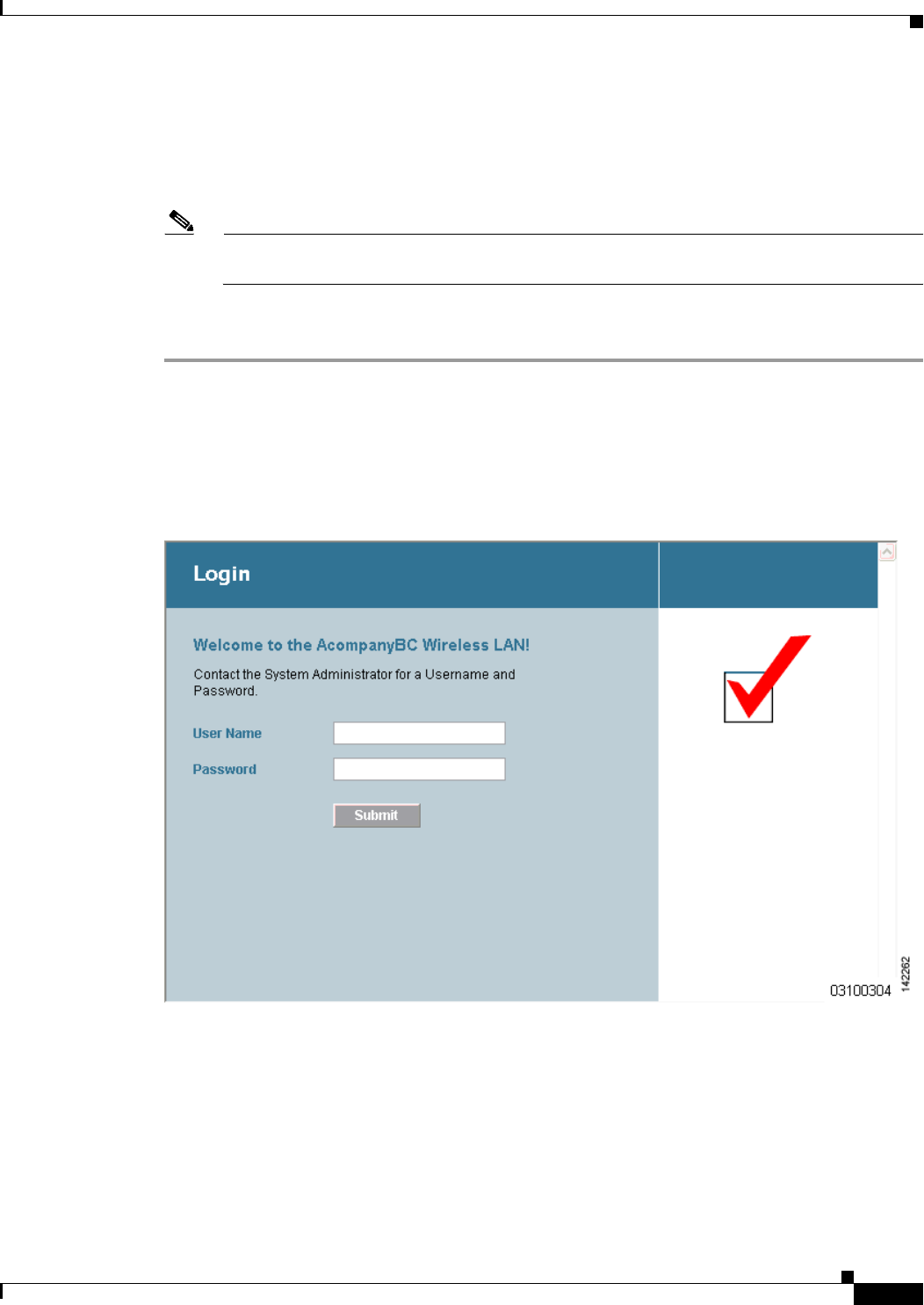
11-15
Cisco Wireless LAN Controller Configuration Guide
OL-21524-02
Chapter 11 Managing User Accounts
Choosing the Web Authentication Login Page
TFTP Image transfer starting.
Image installed.
j. Save your settings by entering this command:
save config
Note If you ever want to remove this logo from the web authentication login page, enter the clear
webimage command.
Step 9 Follow the instructions in the “Using the CLI to Verify the Web Authentication Login Page Settings”
section on page 11-23 to verify your settings.
Modified Default Web Authentication Login Page Example
Figure 11-12 shows an example of a modified default web authentication login page.
Figure 11-12 Modified Default Web Authentication Login Page Example
These CLI commands were used to create this login page:
• config custom-web weblogo disable
• config custom-web webtitle Welcome to the AcompanyBC Wireless LAN!
• config custom-web webmessage Contact the System Administrator for a Username and Password.
• transfer download start
Information similar to the following appears:

11-16
Cisco Wireless LAN Controller Configuration Guide
OL-21524-02
Chapter 11 Managing User Accounts
Choosing the Web Authentication Login Page
Mode........................................... TFTP
Data Type...................................... Login Image
TFTP Server IP................................. xxx.xxx.xxx.xxx
TFTP Path...................................... /
TFTP Filename..................................... Logo.gif
This may take some time.
Are you sure you want to start? (y/n) y
TFTP Image transfer starting.
Image installed.
config custom-web redirecturl url
• show custom-web
Cisco Logo.................. Disabled
CustomLogo.................. 00_logo.gif
Custom Title................ Welcome to the AcompanyBC Wireless LAN!
Custom Message ............. Contact the System Administrator for a Username and Password.
Custom Redirect URL......... http://www.AcompanyBC.com
Web Authentication Mode..... Disabled
Web Authentication URL........ Disabled
Creating a Customized Web Authentication Login Page
This section provides information on creating a customized web authentication login page, which can
then be accessed from an external web server.
Here is a web authentication login page template. It can be used as a model when creating your own
customized page:
<html>
<head>
<meta http-equiv="Pragma" content="no-cache">
<meta HTTP-EQUIV="Content-Type" CONTENT="text/html; charset=iso-8859-1">
<title>Web Authentication</title>
<script>
function submitAction(){
var link = document.location.href;
var searchString = "redirect=";
var equalIndex = link.indexOf(searchString);
var redirectUrl = "";
if (document.forms[0].action == "") {
var url = window.location.href;
var args = new Object();
var query = location.search.substring(1);
var pairs = query.split("&");
for(var i=0;i<pairs.length;i++){
var pos = pairs[i].indexOf('=');
if(pos == -1) continue;
var argname = pairs[i].substring(0,pos);
var value = pairs[i].substring(pos+1);
args[argname] = unescape(value);
}
document.forms[0].action = args.switch_url;
}
if(equalIndex >= 0) {
equalIndex += searchString.length;
redirectUrl = "";
redirectUrl += link.substring(equalIndex);

11-17
Cisco Wireless LAN Controller Configuration Guide
OL-21524-02
Chapter 11 Managing User Accounts
Choosing the Web Authentication Login Page
}
if(redirectUrl.length > 255)
redirectUrl = redirectUrl.substring(0,255);
document.forms[0].redirect_url.value = redirectUrl;
document.forms[0].buttonClicked.value = 4;
document.forms[0].submit();
}
function loadAction(){
var url = window.location.href;
var args = new Object();
var query = location.search.substring(1);
var pairs = query.split("&");
for(var i=0;i<pairs.length;i++){
var pos = pairs[i].indexOf('=');
if(pos == -1) continue;
var argname = pairs[i].substring(0,pos);
var value = pairs[i].substring(pos+1);
args[argname] = unescape(value);
}
//alert( "AP MAC Address is " + args.ap_mac);
//alert( "The Switch URL to post user credentials is " + args.switch_url);
//document.forms[0].action = args.switch_url;
// This is the status code returned from webauth login action
// Any value of status code from 1 to 5 is error condition and user
// should be shown error as below or modify the message as it suits
// the customer
if(args.statusCode == 1){
alert("You are already logged in. No further action is required on your part.");
}
else if(args.statusCode == 2){
alert("You are not configured to authenticate against web portal. No further
action is required on your part.");
}
else if(args.statusCode == 3){
alert("The username specified cannot be used at this time. Perhaps the username is
already logged into the system?");
}
else if(args.statusCode == 4){
alert("The User has been excluded. Please contact the administrator.");
}
else if(args.statusCode == 5){
alert("Invalid username and password. Please try again.");
}
}
</script>
</head>
<body topmargin="50" marginheight="50" onload="loadAction();">
<form method="post" action="https://209.165.200.225/login.html">
<input TYPE="hidden" NAME="buttonClicked" SIZE="16" MAXLENGTH="15" value="0">
<input TYPE="hidden" NAME="redirect_url" SIZE="255" MAXLENGTH="255" VALUE="">
<input TYPE="hidden" NAME="err_flag" SIZE="16" MAXLENGTH="15" value="0">
<div align="center">
<table border="0" cellspacing="0" cellpadding="0">
<tr> <td> </td></tr>
<tr align="center"> <td colspan="2"><font size="10" color="#336699">Web
Authentication</font></td></tr>
<tr align="center">

11-18
Cisco Wireless LAN Controller Configuration Guide
OL-21524-02
Chapter 11 Managing User Accounts
Choosing the Web Authentication Login Page
<td colspan="2"> User Name <input type="TEXT" name="username" SIZE="25"
MAXLENGTH="63" VALUE="">
</td>
</tr>
<tr align="center" >
<td colspan="2"> Password <input type="Password"
name="password" SIZE="25" MAXLENGTH="24">
</td>
</tr>
<tr align="center">
<td colspan="2"><input type="button" name="Submit" value="Submit" class="button"
onclick="submitAction();">
</td>
</tr>
</table>
</div>
</form>
</body>
</html>
These parameters are added to the URL when the user’s Internet browser is redirected to the customized
login page:
• ap_mac—The MAC address of the access point to which the wireless user is associated.
• switch_url—The URL of the controller to which the user credentials should be posted.
• redirect—The URL to which the user is redirected after authentication is successful.
• statusCode—The status code returned from the controller’s web authentication server.
• wlan—The WLAN SSID to which the wireless user is associated.
The available status codes are as follows:
• Status Code 1: “You are already logged in. No further action is required on your part.”
• Status Code 2: “You are not configured to authenticate against web portal. No further action is
required on your part.”
• Status Code 3: “The username specified cannot be used at this time. Perhaps the username is already
logged into the system?”
• Status Code 4: “You have been excluded.”
• Status Code 5: “The User Name and Password combination you have entered is invalid. Please try
again.”
Note For additional information, see the External Web Authentication with Wireless LAN Controllers
Configuration Example at this URL:
http://www.cisco.com/en/US/tech/tk722/tk809/technologies_configuration_example09186a008076f97
4.shtml
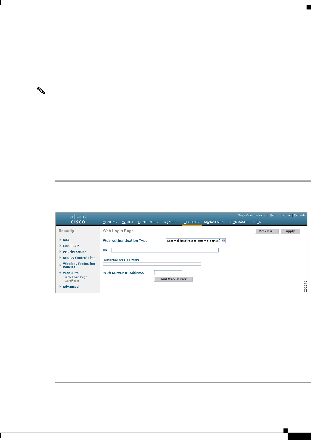
11-19
Cisco Wireless LAN Controller Configuration Guide
OL-21524-02
Chapter 11 Managing User Accounts
Choosing the Web Authentication Login Page
Using a Customized Web Authentication Login Page from an External Web
Server
If you want to use a customized web authentication login page that you configured on an external web
server, follow the instructions in the GUI or CLI procedure below. When you enable this feature, the user
is directed to your customized login page on the external web server.
Note For Cisco 5500 Series Controllers, Cisco 2100 Series Controller, and controller network modules, you
must configure a preauthentication access control list (ACL) on the WLAN for the external web server
and then choose this ACL as the WLAN preauthentication ACL under Security Policies > Web Policy
on the WLANs > Edit page. See Chapter 6, “Configuring Security Solutions,” for more information on
ACLs.
Using the GUI to Choose a Customized Web Authentication Login Page from an External Web Server
To choose a customized web authentication login page from an external server using the controller GUI,
follow these steps:
Step 1 Choose Security > Web Auth > Web Login Page to open the Web Login page (see Figure 11-13).
Figure 11-13 Web Login Page
Step 2 From the Web Authentication Type drop-down list, choose External (Redirect to external server).
Step 3 In the URL text box, enter the URL of the customized web authentication login page on your web server.
You can enter up to 252 characters.
Step 4 In the Web Server IP Address text box, enter the IP address of your web server. Your web server should
be on a different network from the controller service port network.
Step 5 Click Add Web Server. This server now appears in the list of external web servers.
Step 6 Click Apply to commit your changes.
Step 7 If you are satisfied with the content and appearance of the login page, click Save Configuration to save
your changes.

11-20
Cisco Wireless LAN Controller Configuration Guide
OL-21524-02
Chapter 11 Managing User Accounts
Choosing the Web Authentication Login Page
Using the CLI to Choose a Customized Web Authentication Login Page from an External Web Server
To choose a customized web authentication login page from an external server using the controller CLI,
follow these steps:
Step 1 Specify the web authentication type by entering this command:
config custom-web webauth_type external
Step 2 Specify the URL of the customized web authentication login page on your web server by entering this
command:
config custom-web ext-webauth-url url
You can enter up to 252 characters for the URL.
Step 3 Specify the IP address of your web server by entering this command:
config custom-web ext-webserver {add | delete} server_IP_address
Step 4 Enter the save config command to save your settings.
Step 5 Follow the instructions in the “Using the CLI to Verify the Web Authentication Login Page Settings”
section on page 11-23 to verify your settings.
Downloading a Customized Web Authentication Login Page
You can compress the page and image files used for displaying a web authentication login page into a.tar
file for download to a controller. These files are known as the webauth bundle. The maximum allowed
size of the files in their uncompressed state is 1 MB. When the .tar file is downloaded from a local TFTP
server, it enters the controller’s file system as an untarred file.
Note If you load a webauth bundle with a .tar compression application that is not GNU compliant, the
controller cannot extract the files in the bundle and the following error messages appear: “Extracting
error” and “TFTP transfer failed.” Therefore, we recommend that you use an application that complies
with GNU standards, such as PicoZip, to compress the .tar file for the webauth bundle.
Note Configuration backups do not include extra files or components, such as the webauth bundle or external
licenses, that you download and store on your controller, so you should manually save external backup
copies of those files or components.
Note If the customized webauth bundle has more than 3 separated elements, we advise you to use an external
server to prevent page load issues that may be caused because of TCP rate-limiting policy on the
controller.
Follow these guidelines when preparing the customized login page:
• Name the login page “login.html.” The controller prepares the web authentication URL based on this
name. If the server does not find this file after the webauth bundle has been untarred, the bundle is
discarded, and an error message appears.
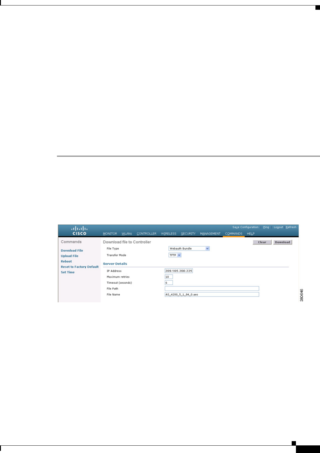
11-21
Cisco Wireless LAN Controller Configuration Guide
OL-21524-02
Chapter 11 Managing User Accounts
Choosing the Web Authentication Login Page
• Include input text boxes for both a username and password.
• Retain the redirect URL as a hidden input item after extracting from the original URL.
• Extract and set the action URL in the page from the original URL.
• Include scripts to decode the return status code.
• Make sure that all paths used in the main page (to refer to images, for example).
You can download a login page example from Cisco WCS and use it as a starting point for your
customized login page. See the “Downloading a Customized Web Auth Page” section in the Using
Templates chapter of the Cisco Wireless Control System Configuration Guide, Release 7.0, for
instructions.
Using the GUI to Download a Customized Web Authentication Login Page
To download a customized web authentication login page from the controller GUI, follow these steps:
Step 1 Make sure that you have a TFTP server available for the file download. See the guidelines for setting up
a TFTP server in Step 8 of the “Using the CLI to Choose the Default Web Authentication Login Page”
section on page 11-13.
Step 2 Copy the .tar file containing your login page to the default directory on your TFTP server.
Step 3 Choose Commands > Download File to open the Download File to Controller page (see Figure 11-14).
Figure 11-14 Download File to Controller Page
Step 4 From the File Type drop-down list, choose Webauth Bundle.
Step 5 From the Transfer Mode drop-down list, choose TFTP or FTP.
Step 6 In the IP Address text box, enter the IP address of the TFTP server.
Step 7 If you are using a TFTP server, enter the maximum number of times the controller should attempt to
download the .tar file in the Maximum Retries text box.
The range is 1 to 254.
The default is 10.
Step 8 If you are using a TFTP server, enter the amount of time in seconds before the controller times out while
attempting to download the *.tar file in the Timeout text box.
The range is 1 to 254 seconds.
The default is 6 seconds.

11-22
Cisco Wireless LAN Controller Configuration Guide
OL-21524-02
Chapter 11 Managing User Accounts
Choosing the Web Authentication Login Page
Step 9 In the File Path text box, enter the path of the .tar file to be downloaded. The default value is “/.”
Step 10 In the File Name text box, enter the name of the .tar file to be downloaded.
Step 11 If you are using an FTP server, follow these steps:
a. In the Server Login Username text box, enter the username to log into the FTP server.
b. In the Server Login Password text box, enter the password to log into the FTP server.
c. In the Server Port Number text box, enter the port number on the FTP server through which the
download occurs. The default value is 21.
Step 12 Click Download to download the .tar file to the controller.
Step 13 Choose Security > Web Auth > Web Login Page to open the Web Login page.
Step 14 From the Web Authentication Type drop-down list, choose Customized (Downloaded).
Step 15 Click Apply to commit your changes.
Step 16 Click Preview to view your customized web authentication login page.
Step 17 If you are satisfied with the content and appearance of the login page, click Save Configuration to save
your changes.
Using the CLI to Download a Customized Web Authentication Login Page
To download a customized web authentication login page using the controller CLI, follow these steps:
Step 1 Make sure that you have a TFTP server available for the file download. See the guidelines for setting up
a TFTP server in Step 8 of the “Using the CLI to Choose the Default Web Authentication Login Page”
section on page 11-13.
Step 2 Copy the .tar file containing your login page to the default directory on your TFTP server.
Step 3 Specify the download mode by entering this command:
transfer download mode tftp
Step 4 Specify the type of file to be downloaded by entering this command:
transfer download datatype webauthbundle
Step 5 Specify the IP address of the TFTP server by entering this command:
transfer download serverip tftp-server-ip-address.
Note Some TFTP servers require only a forward slash (/) as the TFTP server IP address, and the TFTP
server automatically determines the path to the correct directory.
Step 6 Specify the download path by entering this command:
transfer download path absolute-tftp-server-path-to-file
Step 7 Specify the file to be downloaded by entering this command:
transfer download filename filename.tar
Step 8 View your updated settings and answer y to the prompt to confirm the current download settings and start
the download by entering this command:
transfer download start
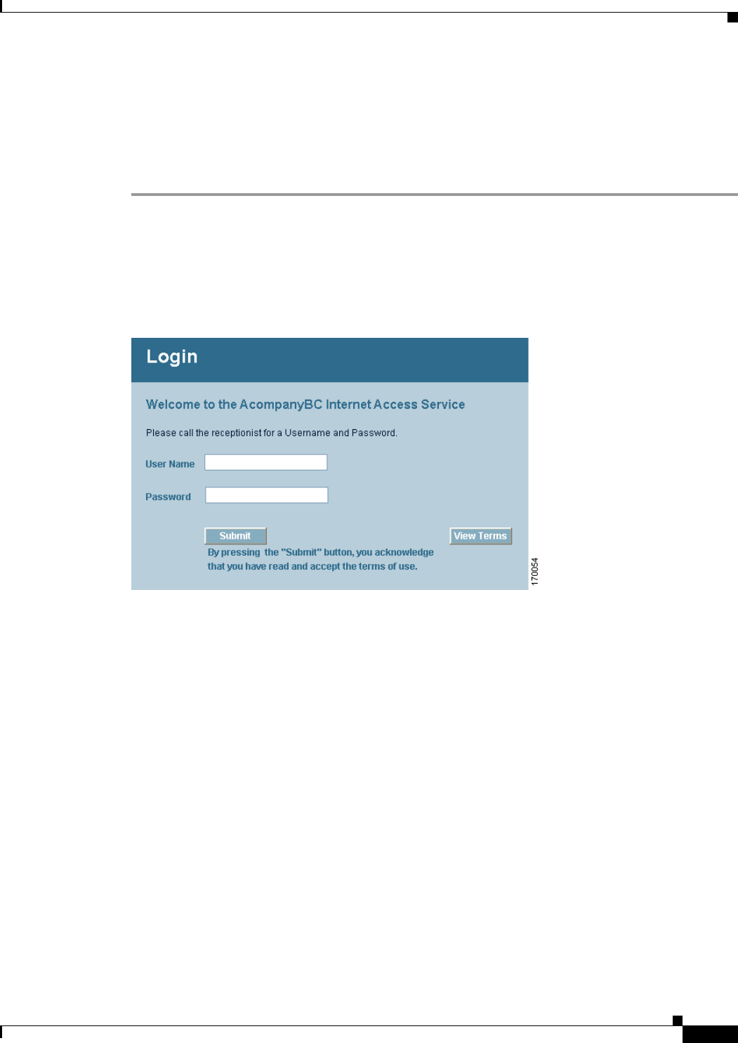
11-23
Cisco Wireless LAN Controller Configuration Guide
OL-21524-02
Chapter 11 Managing User Accounts
Choosing the Web Authentication Login Page
Step 9 Specify the web authentication type by entering this command:
config custom-web webauth_type customized
Step 10 Enter the save config command to save your settings.
Step 11 Follow the instructions in the “Using the CLI to Verify the Web Authentication Login Page Settings”
section on page 11-23 to verify your settings.
Customized Web Authentication Login Page Example
Figure 11-15 shows an example of a customized web authentication login page.
Figure 11-15 Customized Web Authentication Login Page Example
Using the CLI to Verify the Web Authentication Login Page Settings
Enter the show custom-web command to verify your changes to the web authentication login page. This
example shows the information that appears when the configuration settings are set to default values:
Cisco Logo..................................... Enabled
CustomLogo..................................... Disabled
Custom Title................................... Disabled
Custom Message................................. Disabled
Custom Redirect URL............................ Disabled
Web Authentication Mode........................ Disabled
Web Authentication URL......................... Disabled
This example shows the information that appears when the configuration settings have been modified:
Cisco Logo..................................... Disabled
CustomLogo..................................... 00_logo.gif
Custom Title................................... Welcome to the AcompanyBC Wireless LAN!
Custom Message................................. Contact the System Administrator for a
Username and Password.

11-24
Cisco Wireless LAN Controller Configuration Guide
OL-21524-02
Chapter 11 Managing User Accounts
Choosing the Web Authentication Login Page
Custom Redirect URL............................
Web Authentication Mode........................ Internal
Web Authentication URL............................ Disabled
Assigning Login, Login Failure, and Logout Pages per WLAN
You can display different web authentication login, login failure, and logout pages to users per WLAN.
This feature enables user-specific web authentication pages to be displayed for a variety of network
users, such as guest users or employees within different departments of an organization.
Different login pages are available for all web authentication types (internal, external, and customized).
However, different login failure and logout pages can be specified only when you choose customized as
the web authentication type.
Using the GUI to Assign Login, Login Failure, and Logout Pages per WLAN
To assign web login, login failure, and logout pages to a WLAN using the controller GUI, follow these
steps:
Step 1 Choose WLANs to open the WLANs page.
Step 2 Click the ID number of the WLAN to which you want to assign a web login, login failure, or logout page.
Step 3 Choose Security > Layer 3.
Step 4 Make sure that Web Policy and Authentication are selected.
Step 5 To override the global authentication configuration web authentication pages, select the Override
Global Config check box.
Step 6 When the Web Auth Type drop-down list appears, choose one of the following options to define the web
authentication pages for wireless guest users:
• Internal—Displays the default web login page for the controller. This is the default value.
• Customized—Displays custom web login, login failure, and logout pages. If you choose this option,
three separate drop-down lists appear for login, login failure, and logout page selection. You do not
need to define a customized page for all three options. Choose None from the appropriate drop-down
list if you do not want to display a customized page for that option.
Note These optional login, login failure, and logout pages are downloaded to the controller as
webauth.tar files. For details on downloading custom pages, see the “Downloading a
Customized Web Authentication Login Page” section on page 11-20.
• External—Redirects users to an external server for authentication. If you choose this option, you
must also enter the URL of the external server in the URL text box.
You can choose specific RADIUS or LDAP servers to provide external authentication on the
WLANs > Edit (Security > AAA Servers) page. Additionally, you can define the priority in which
the servers provide authentication.
Step 7 If you chose External as the web authentication type in Step 6, choose AAA Servers and choose up to
three RADIUS and LDAP servers using the drop-down lists.

11-25
Cisco Wireless LAN Controller Configuration Guide
OL-21524-02
Chapter 11 Managing User Accounts
Choosing the Web Authentication Login Page
Note The RADIUS and LDAP external servers must already be configured in order to be selectable
options on the WLANs > Edit (Security > AAA Servers) page. You can configure these servers
on the RADIUS Authentication Servers page and LDAP Servers page.
Step 8 Establish the priority in which the servers are contacted to perform web authentication as follows:
Note The default order is local, RADIUS, LDAP.
a. Highlight the server type (local, RADIUS, or LDAP) that you want to be contacted first in the box
next to the Up and Down buttons.
b. Click Up and Down until the desired server type is at the top of the box.
c. Click the < arrow to move the server type to the priority box on the left.
d. Repeat these steps to assign priority to the other servers.
Step 9 Click Apply to commit your changes.
Step 10 Click Save Configuration to save your changes.
Using the CLI to Assign Login, Login Failure, and Logout Pages per WLAN
To assign web login, login failure, and logout pages to a WLAN using the controller CLI, follow these
steps:
Step 1 Determine the ID number of the WLAN to which you want to assign a web login, login failure, or logout
page by entering this command:
show wlan summary
Step 2 If you want wireless guest users to log into a customized web login, login failure, or logout page, enter
these commands to specify the filename of the web authentication page and the WLAN for which it
should display:
• config wlan custom-web login-page page_name wlan_id—Defines a customized login page for a
given WLAN.
• config wlan custom-web loginfailure-page page_name wlan_id—Defines a customized login
failure page for a given WLAN.
Note To use the controller’s default login failure page, enter the config wlan custom-web
loginfailure-page none wlan_id command.
• config wlan custom-web logout-page page_name wlan_id—Defines a customized logout page for
a given WLAN.
Note To use the controller’s default logout page, enter the config wlan custom-web logout-page
none wlan_id command.

11-26
Cisco Wireless LAN Controller Configuration Guide
OL-21524-02
Chapter 11 Managing User Accounts
Configuring Wired Guest Access
Step 3 Redirect wireless guess users to an external server before accessing the web login page by entering this
command to specify the URL of the external server:
config wlan custom-web ext-webauth-url ext_web_url wlan_id
Step 4 Define the order in which web authentication servers are contacted by entering this command:
config wlan security web-auth server-precedence wlan_id {local | ldap | radius} {local | ldap |
radius} {local | ldap | radius}
The default order of server web authentication is local, RADIUS and LDAP.
Note All external servers must be preconfigured on the controller. You can configure them on the
RADIUS Authentication Servers page and the LDAP Servers page.
Step 5 Define which web authentication page displays for a wireless guest user by entering this command:
config wlan custom-web webauth-type {internal | customized | external} wlan_id
where
• internal displays the default web login page for the controller. This is the default value.
• customized displays the custom web login page that was configured in Step 2.
Note You do not need to define the web authentication type in Step 5 for the login failure and
logout pages as they are always customized.
• external redirects users to the URL that was configured in Step 3.
Step 6 Use a WLAN-specific custom web configuration rather than a global custom web configuration by
entering this command:
config wlan custom-web global disable wlan_id
Note If you enter the config wlan custom-web global enable wlan_id command, the custom web
authentication configuration at the global level is used.
Step 7 Save your changes by entering this command:
save config
Configuring Wired Guest Access
Wired guest access enables guest users to connect to the guest access network from a wired Ethernet
connection designated and configured for guest access. Wired guest access ports might be available in a
guest office or through specific ports in a conference room. Like wireless guest user accounts, wired
guest access ports are added to the network using the lobby ambassador feature.
Wired guest access can be configured in a standalone configuration or in a dual-controller configuration
that uses both an anchor controller and a foreign controller. This latter configuration is used to further
isolate wired guest access traffic but is not required for deployment of wired guest access.