Cisco Systems 102075 Cisco Aironet 802.11n Dual Band Access Points User Manual Cisco Wireless LAN Controller Configuration Guide 2
Cisco Systems Inc Cisco Aironet 802.11n Dual Band Access Points Cisco Wireless LAN Controller Configuration Guide 2
Contents
- 1. User manual
- 2. Cisco Wireless LAN Controller Configuration Guide_1
- 3. Cisco Wireless LAN Controller Configuration Guide_2
- 4. Cisco Wireless LAN Controller Configuration Guide_3
- 5. Cisco Wireless LAN Controller Configuration Guide_4
- 6. Cisco Wireless LAN Controller Configuration Guide_5
- 7. Cisco Wireless LAN Controller Configuration Guide_6
- 8. Cisco Wireless LAN Controller Configuration Guide_7
- 9. Cisco Wireless LAN Controller Configuration Guide_8
- 10. Cisco Wireless LAN Controller Configuration Guide_9
- 11. Cisco Wireless LAN Controller Configuration Guide_10
- 12. Cisco Wireless LAN Controller Configuration Guide_11
- 13. User Manual
Cisco Wireless LAN Controller Configuration Guide_2
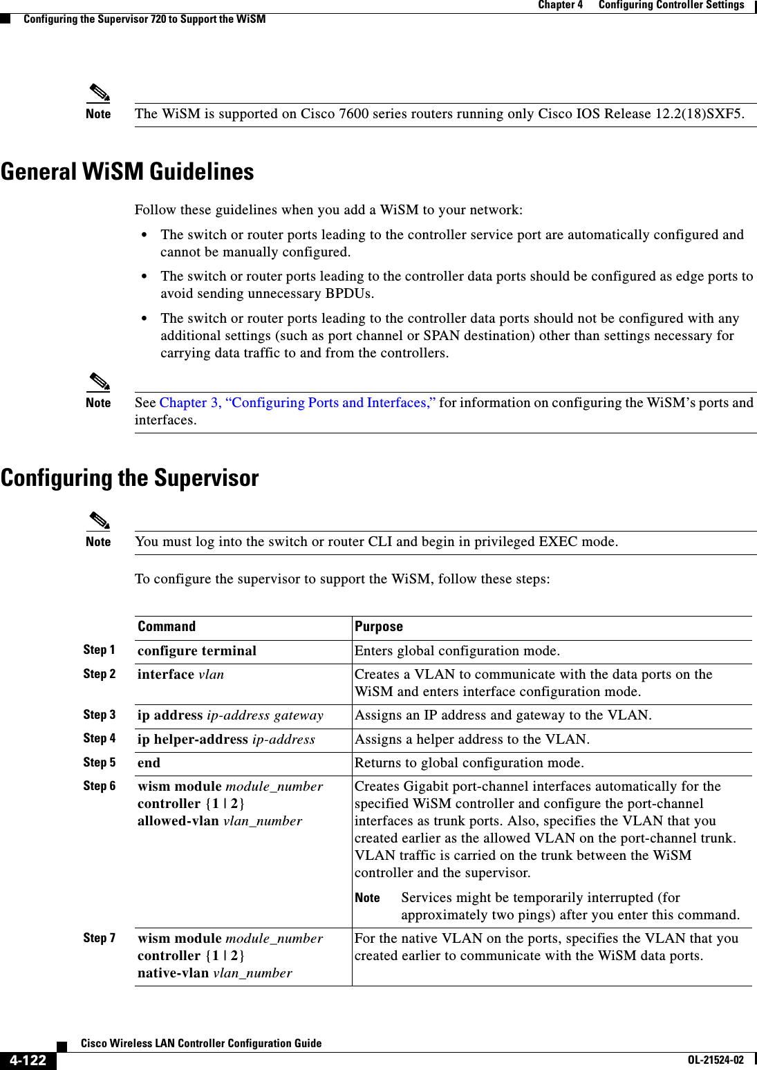
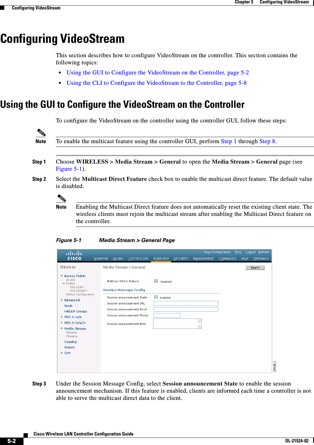
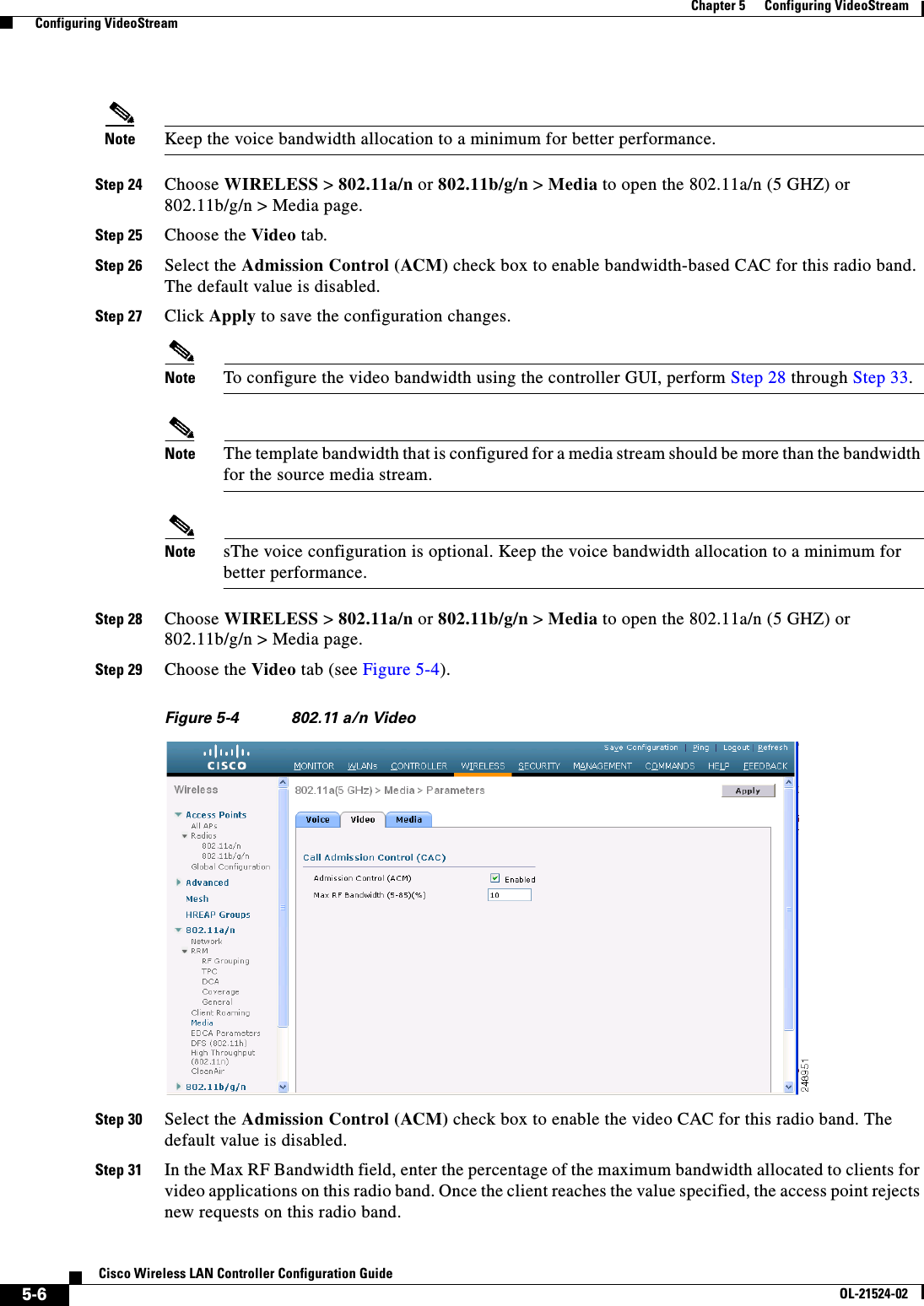
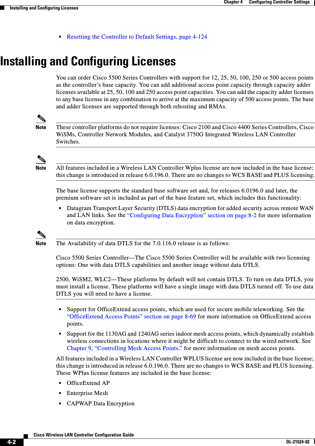
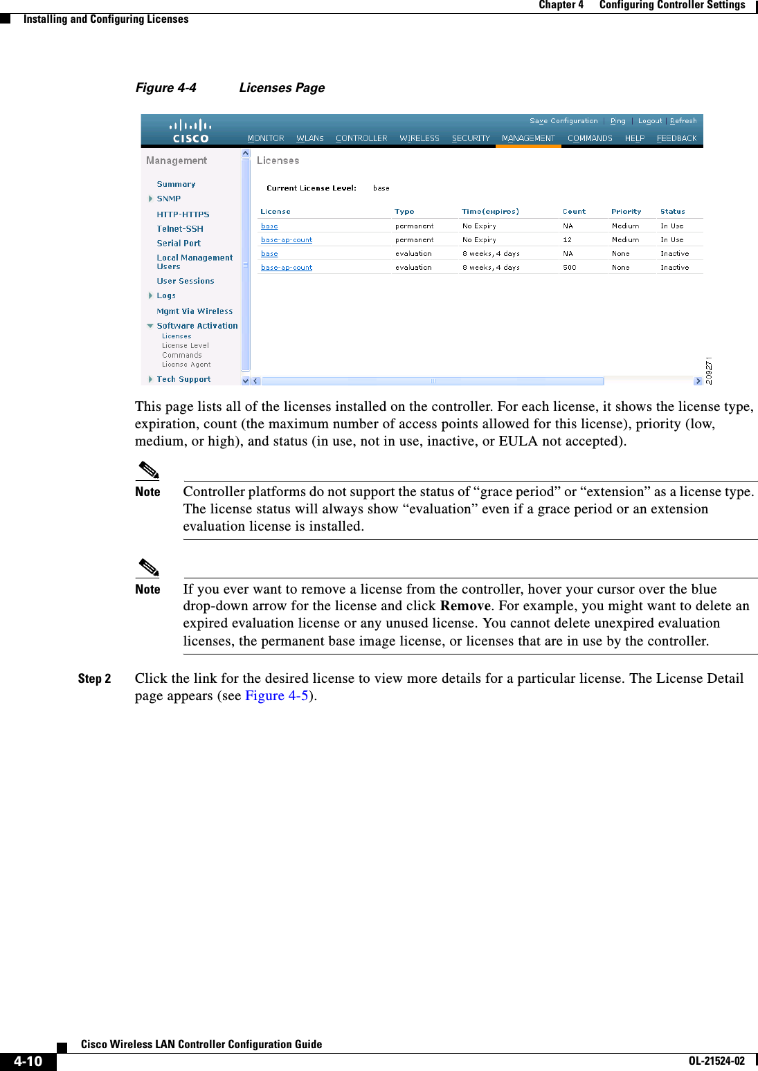
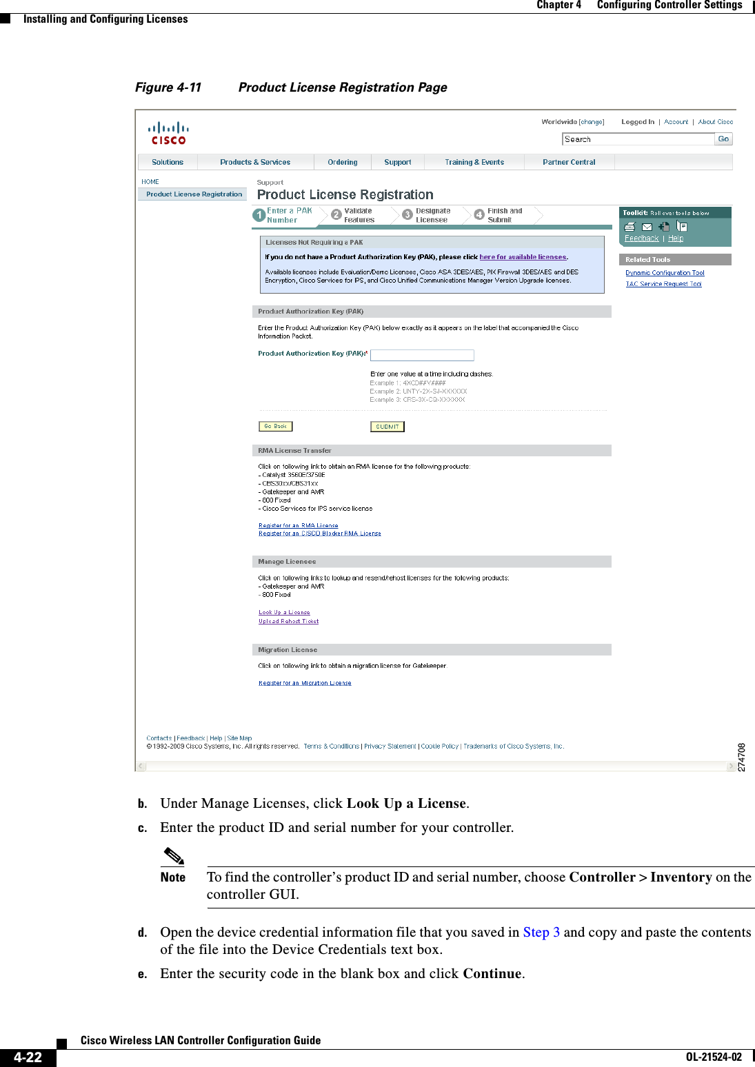
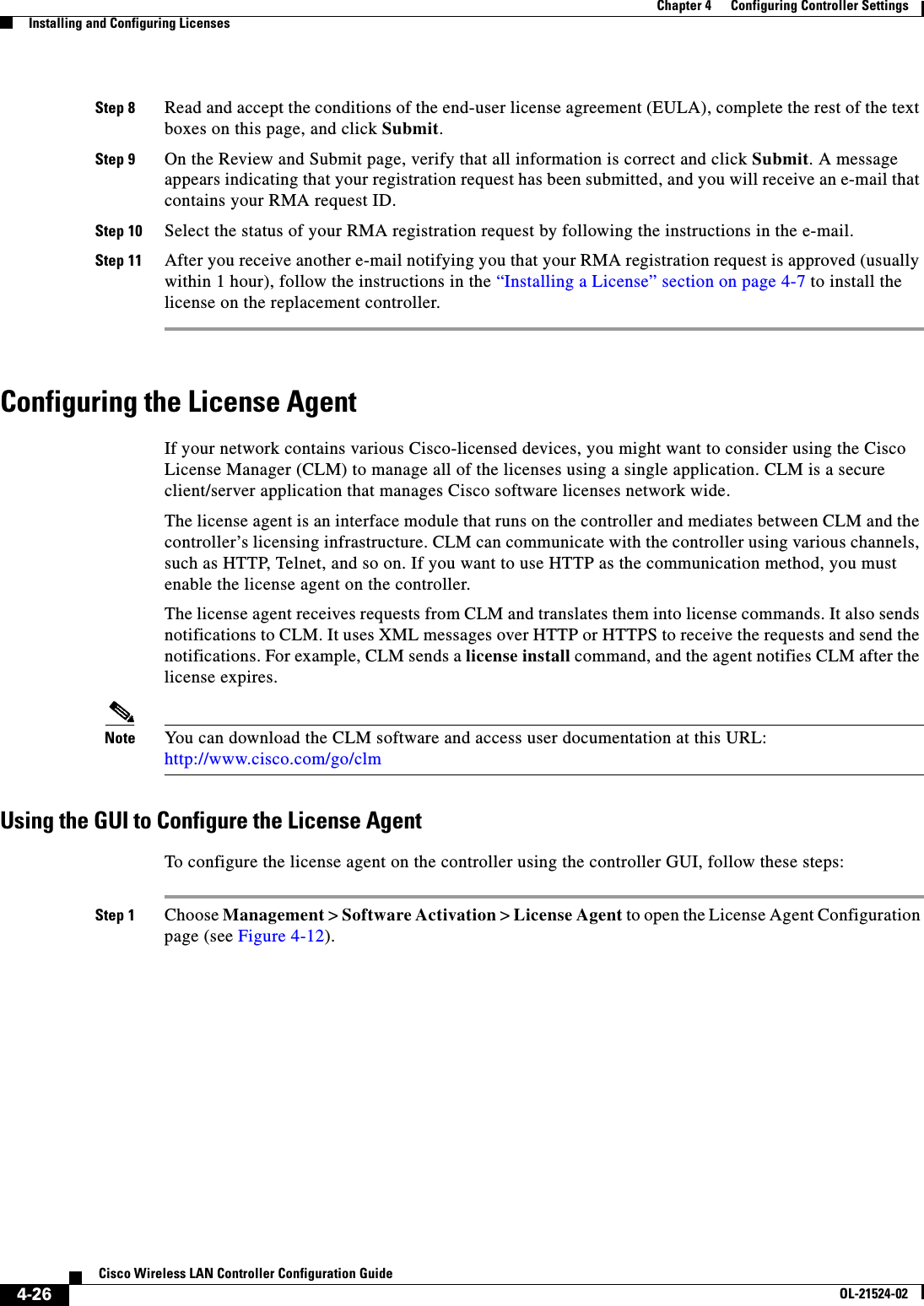
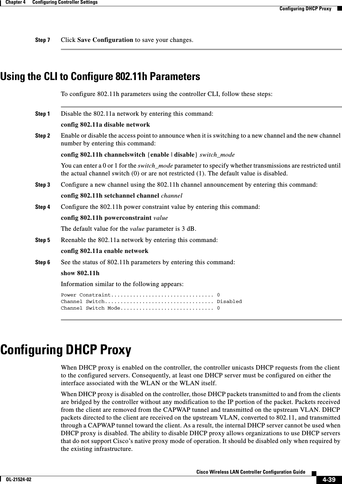
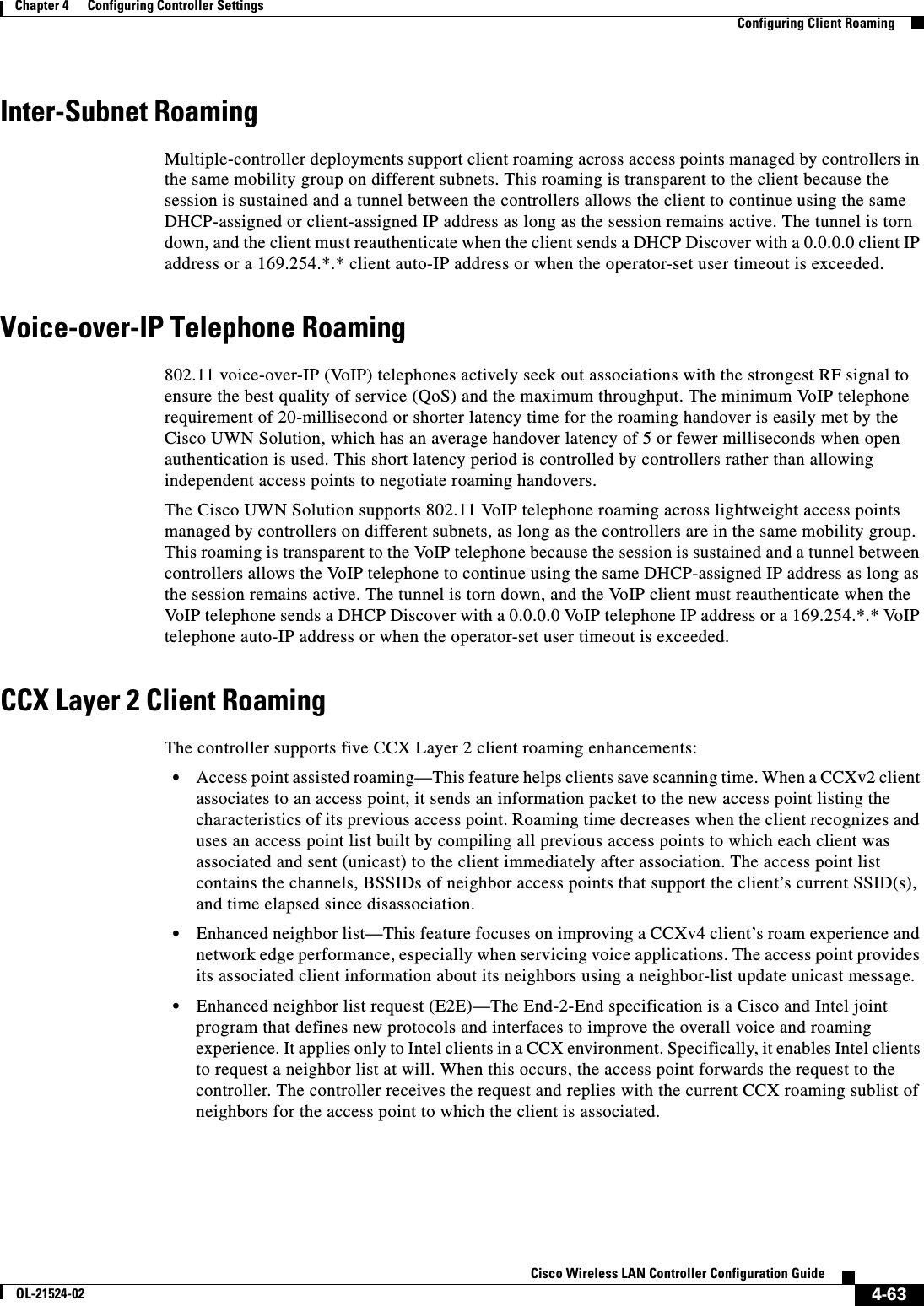
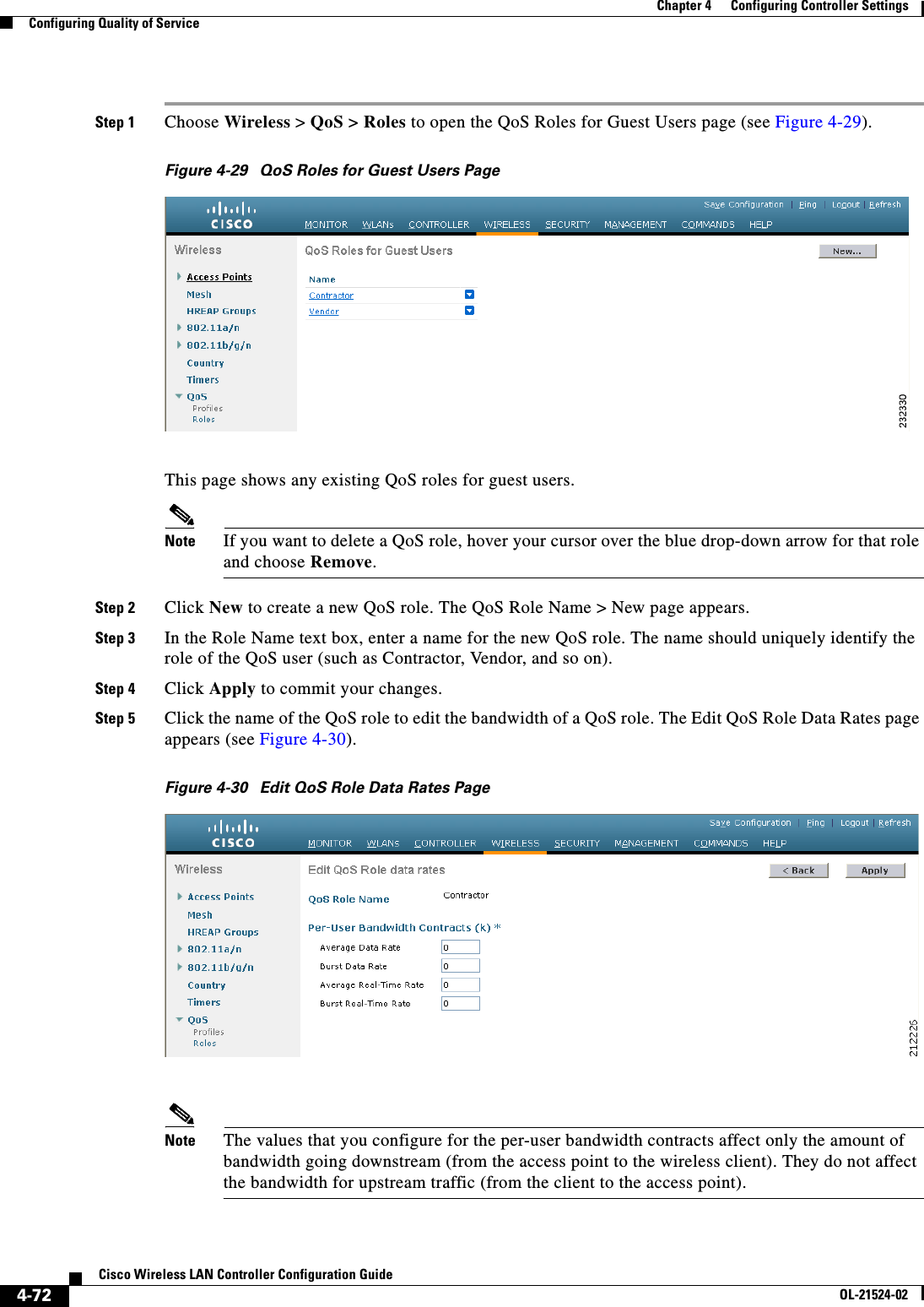
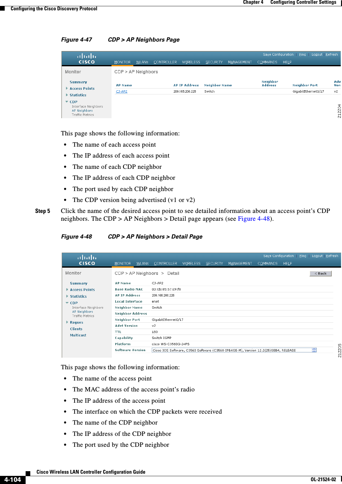
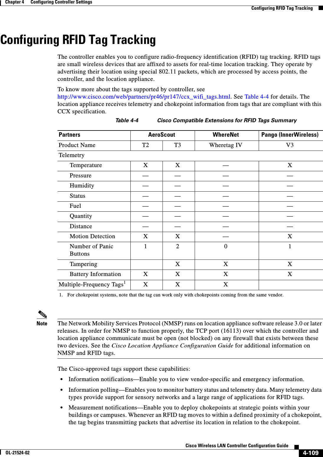
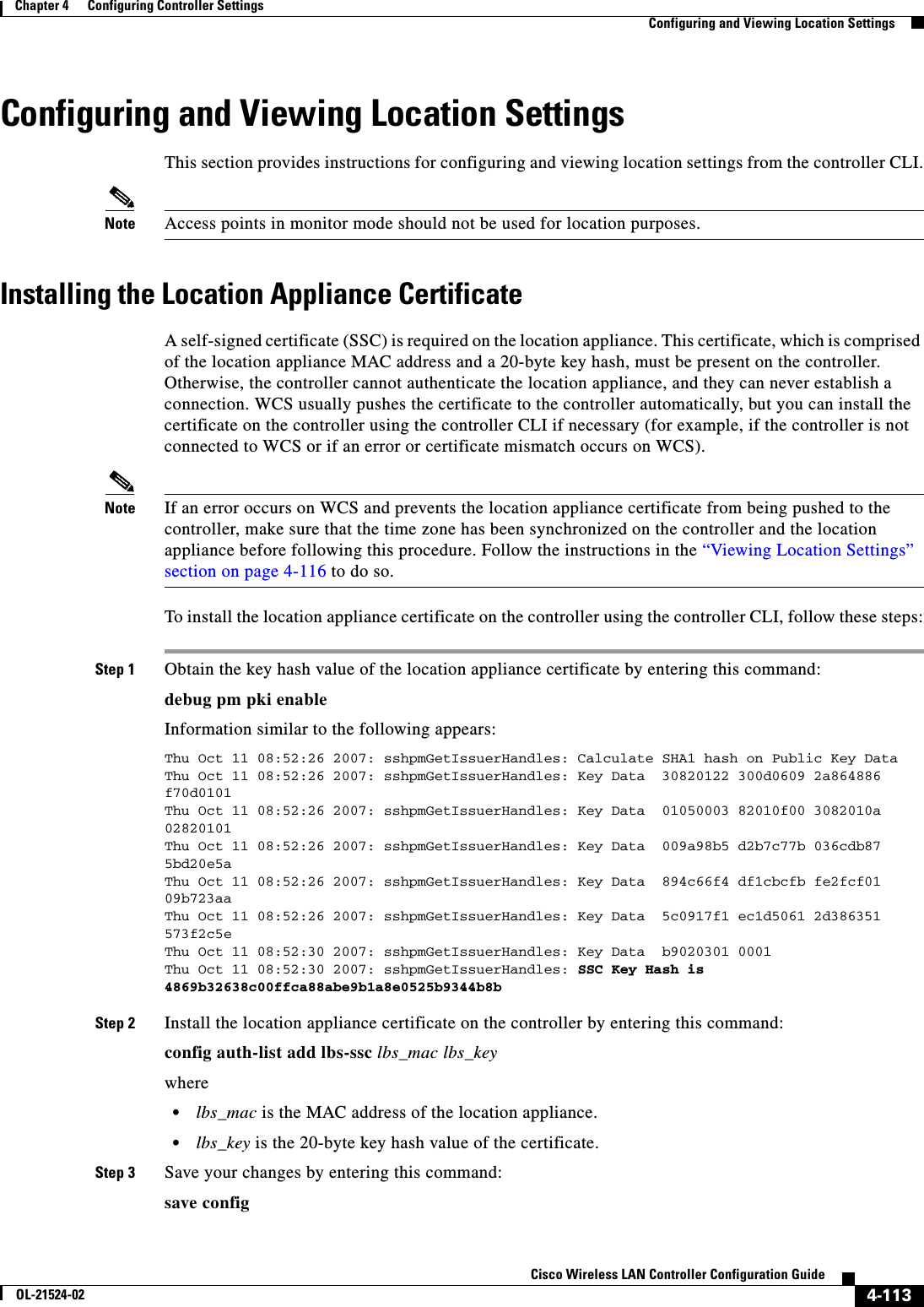
![3-47Cisco Wireless LAN Controller Configuration GuideOL-21524-02Chapter 3 Configuring Ports and Interfaces Configuring Multiple AP-Manager InterfacesUsing the CLI to Create Multiple AP-Manager InterfacesTo create multiple AP-manager interfaces using the controller CLI, follow these steps:Step 1 Enter these commands to create a new interface: • config interface create operator_defined_interface_name {vlan_id | x} • config interface address operator_defined_interface_name ip_addr ip_netmask [gateway] • config interface vlan operator_defined_interface_name {vlan_id | 0} • config interface port operator_defined_interface_name physical_ds_port_number • config interface dhcp operator_defined_interface_name ip_address_of_primary_dhcp_server [ip_address_of_secondary_dhcp_server] • config interface quarantine vlan interface_name vlan_idNote Use this command to configure a quarantine VLAN on any interface. • config interface acl operator_defined_interface_name access_control_list_nameNote See Chapter 6, “Configuring Security Solutions,” for more information on ACLs.Step 2 To make this interface an AP-manager interface, enter this command:config interface ap-manager operator_defined_interface_name {enable | disable}Note Only one AP-manager interface is allowed per physical port. A dynamic interface that is marked as an AP-manager interface cannot be used as a WLAN interface.Step 3 To save your changes, enter this command:save configStep 4 Repeat this procedure for each additional AP-manager interface that you want to create.Cisco 5500 Series Controller ExampleFor a Cisco 5500 Series Controller, we recommend having eight dynamic AP-manager interfaces and associating them to the controller’s eight Gigabit ports. If you are using the management interface, which acts like an AP-manager interface by default, you need to create only seven more dynamic AP-manager interfaces and associate them to the remaining seven Gigabit ports. For example, Figure 3-20 shows a dynamic interface that is enabled as a dynamic AP-manager interface and associated to port number 2, and Figure 3-21 shows a Cisco 5500 Series Controller with LAG disabled, the management interface used as one dynamic AP-manager interface, and seven additional dynamic AP-manager interfaces, each mapped to a different Gigabit port.](https://usermanual.wiki/Cisco-Systems/102075.Cisco-Wireless-LAN-Controller-Configuration-Guide-2/User-Guide-1514962-Page-1.png)

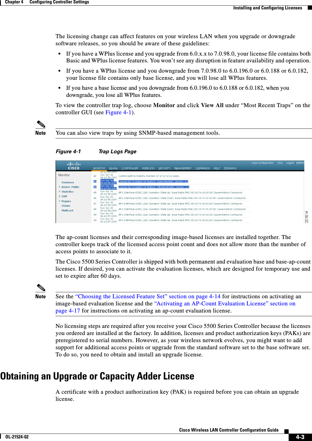
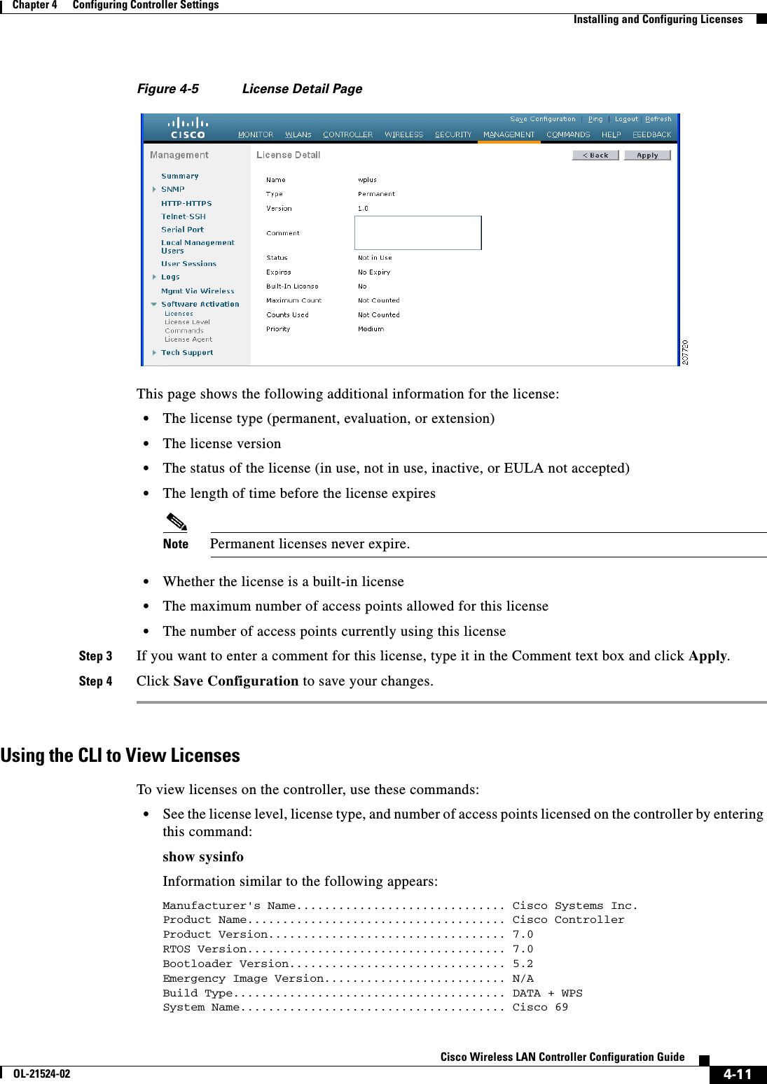
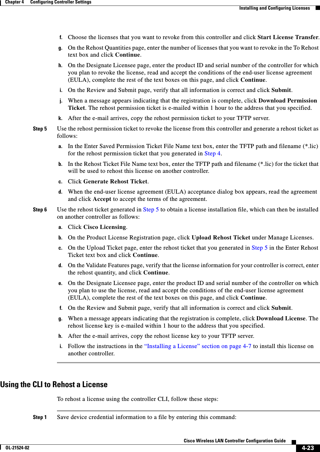
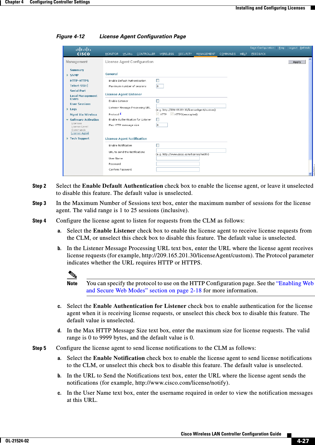
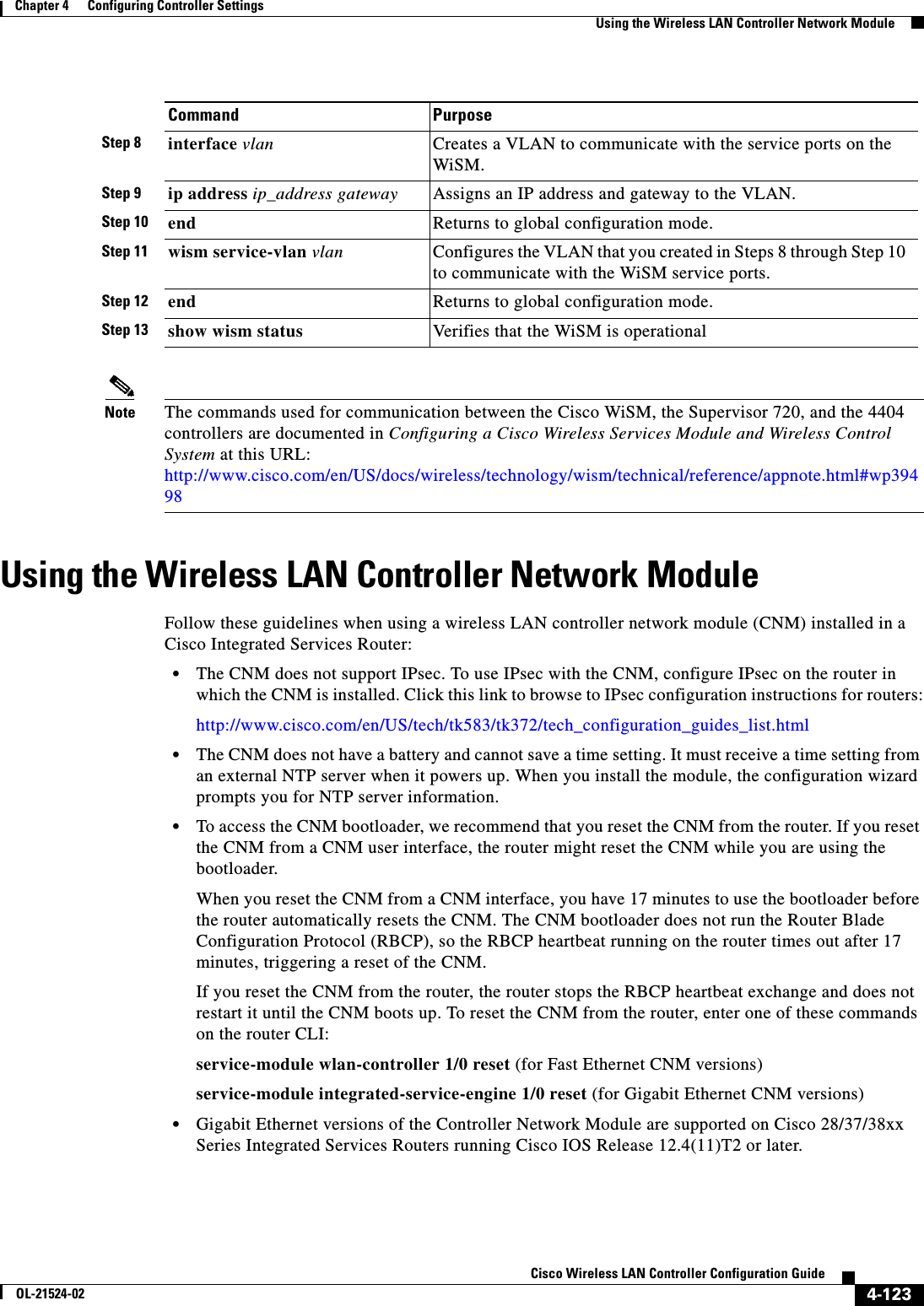
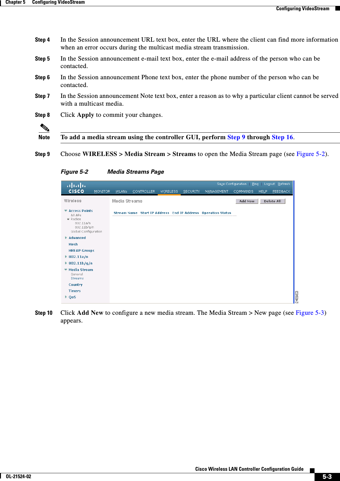
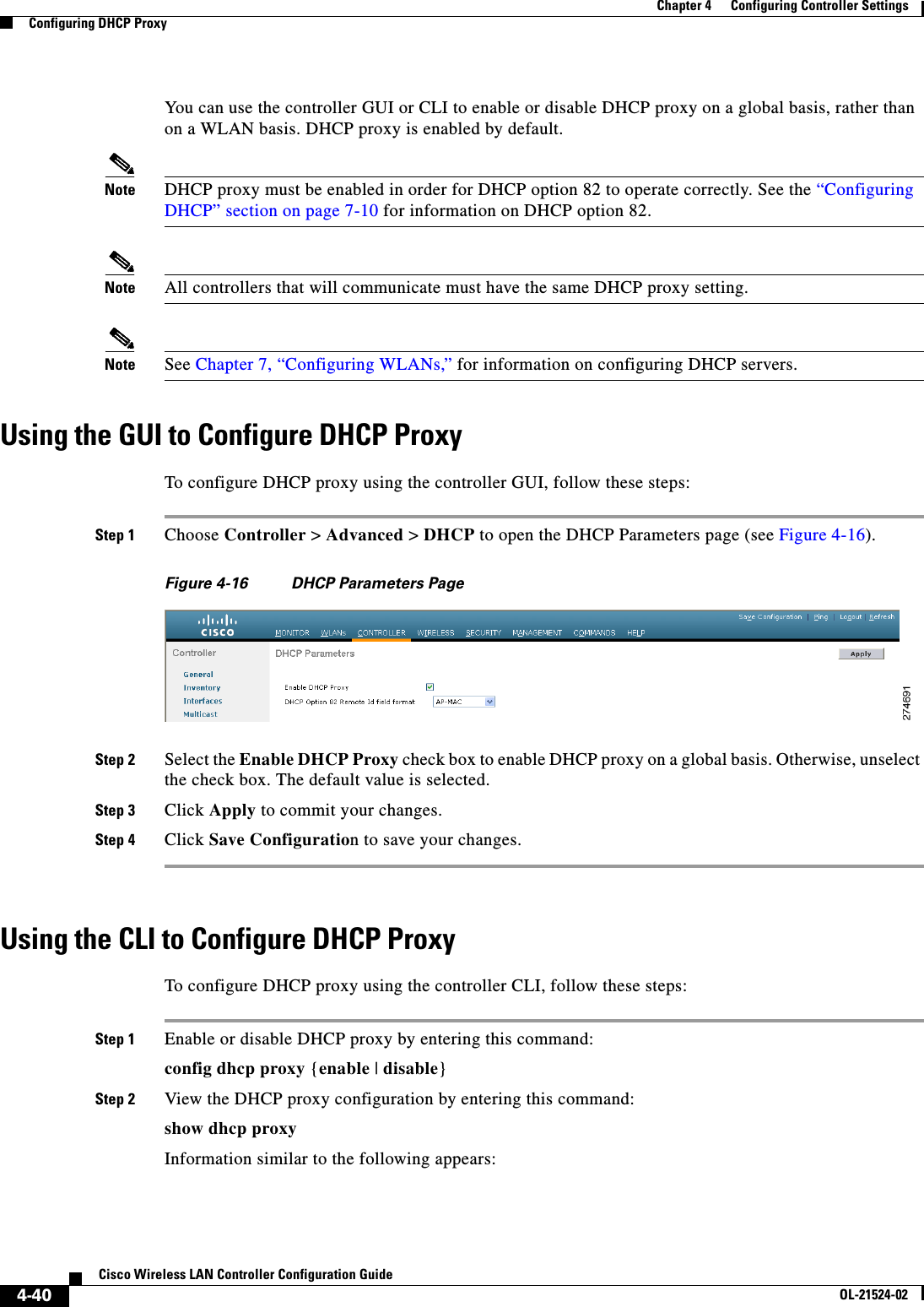
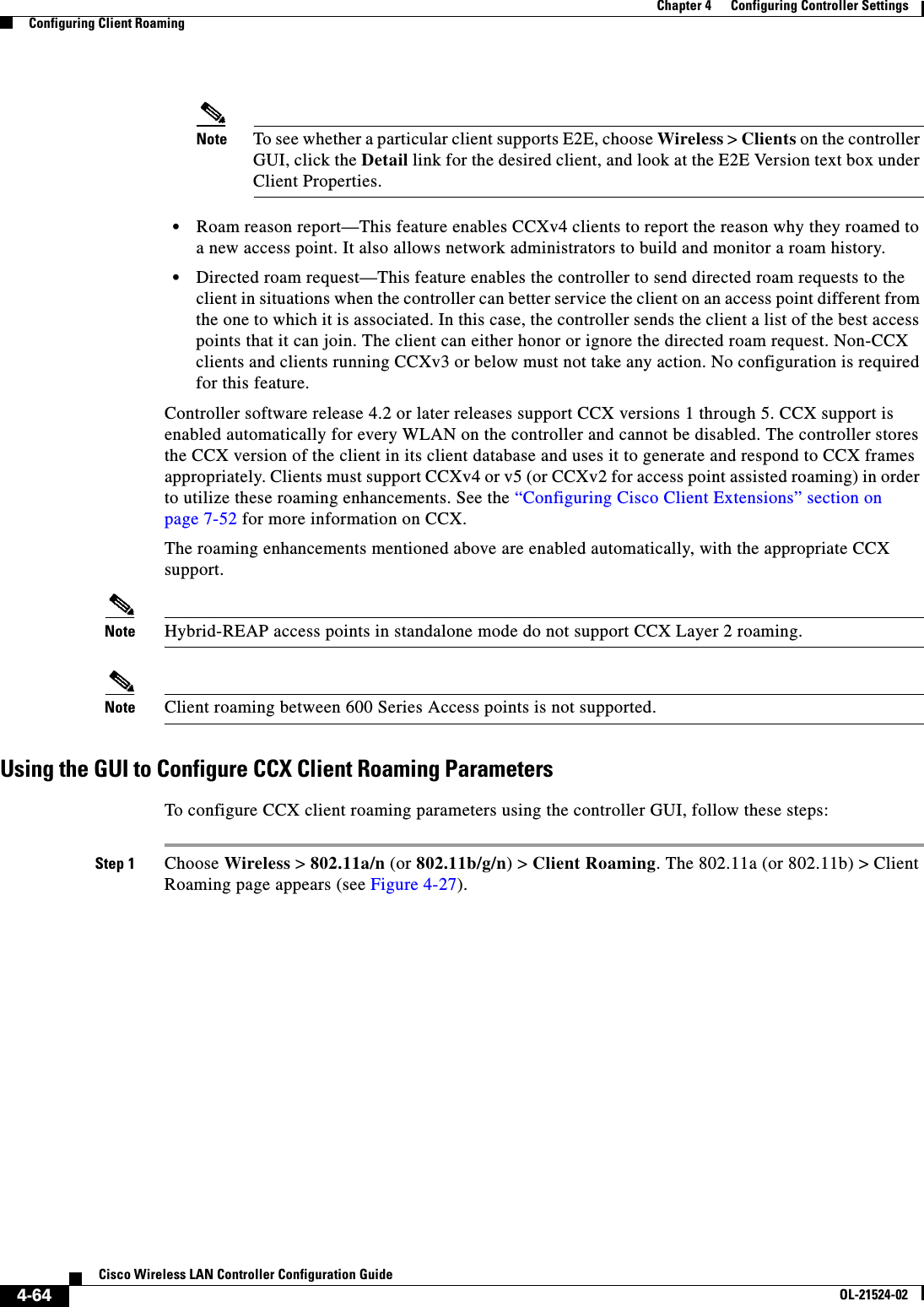
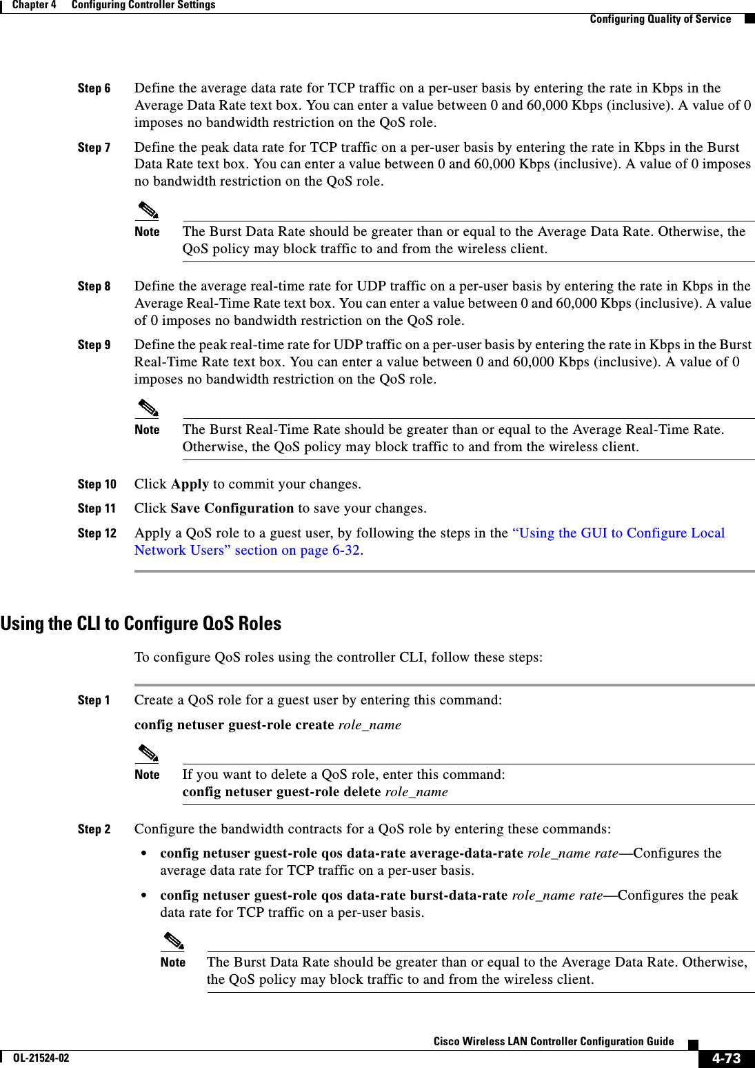
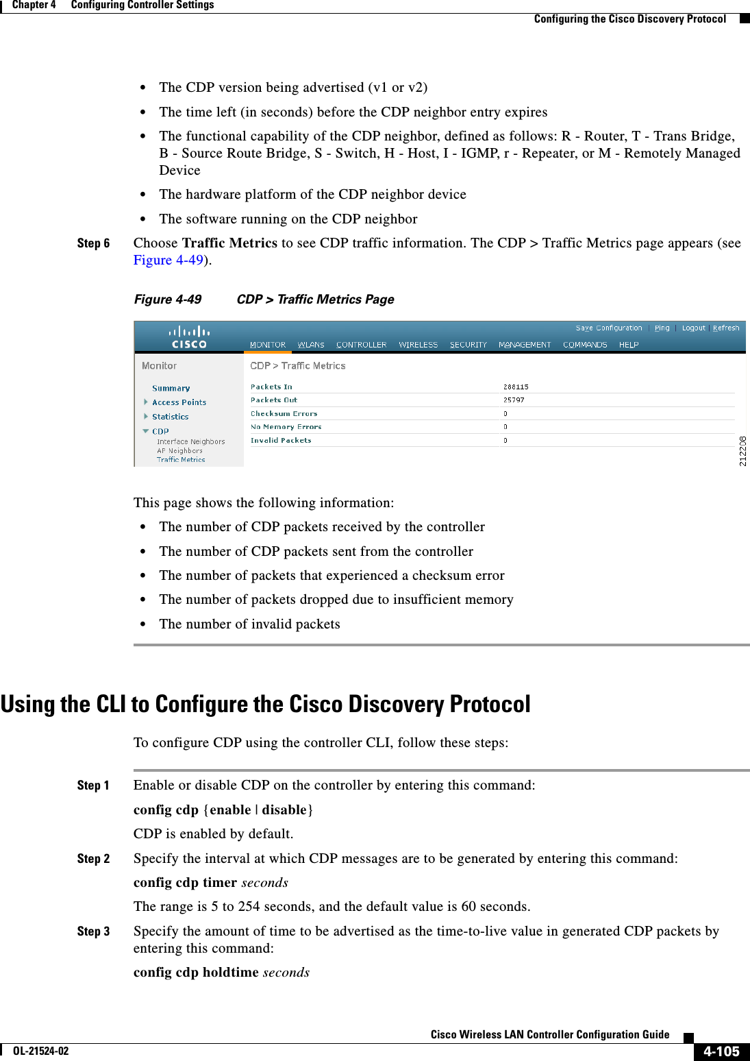
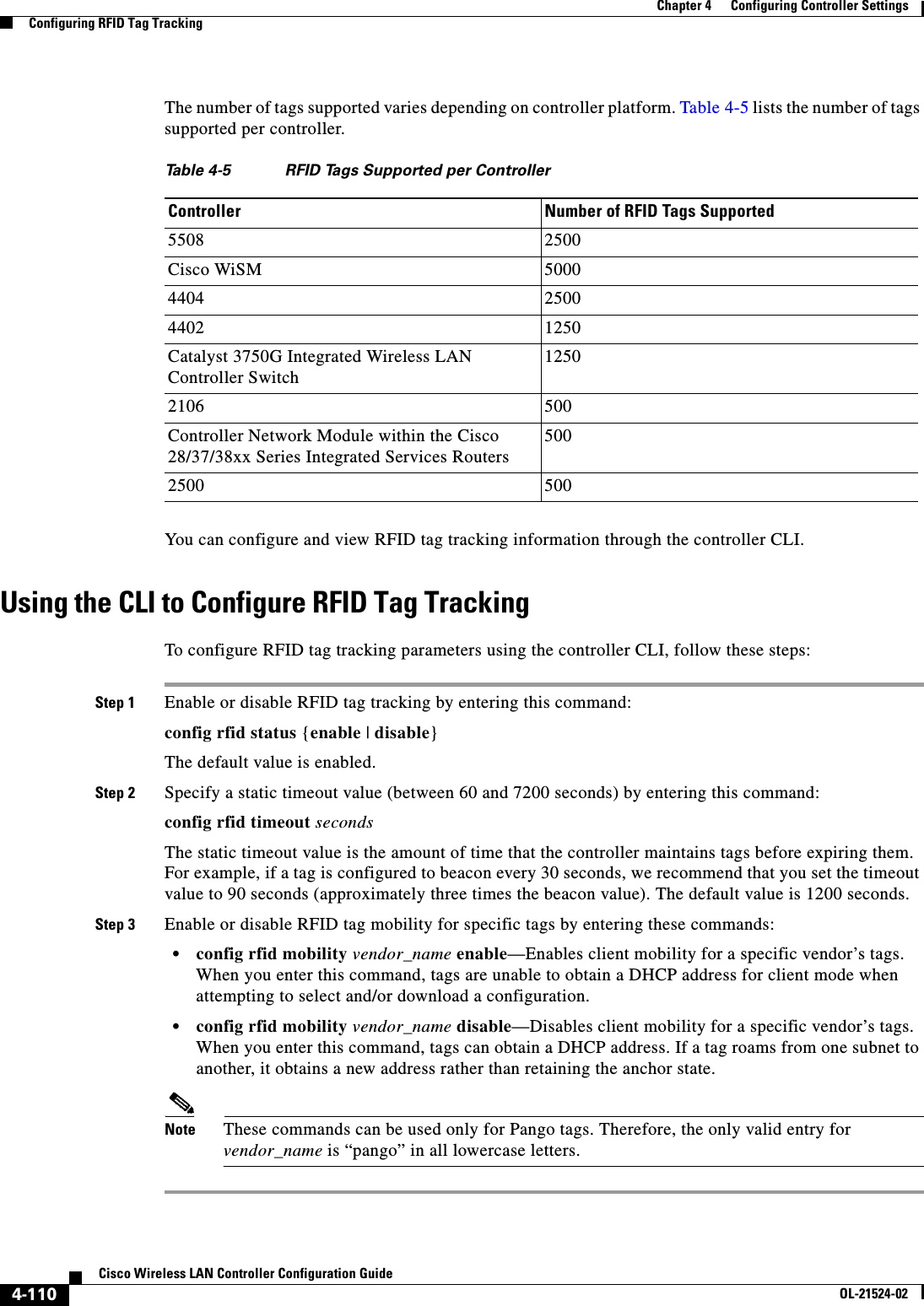
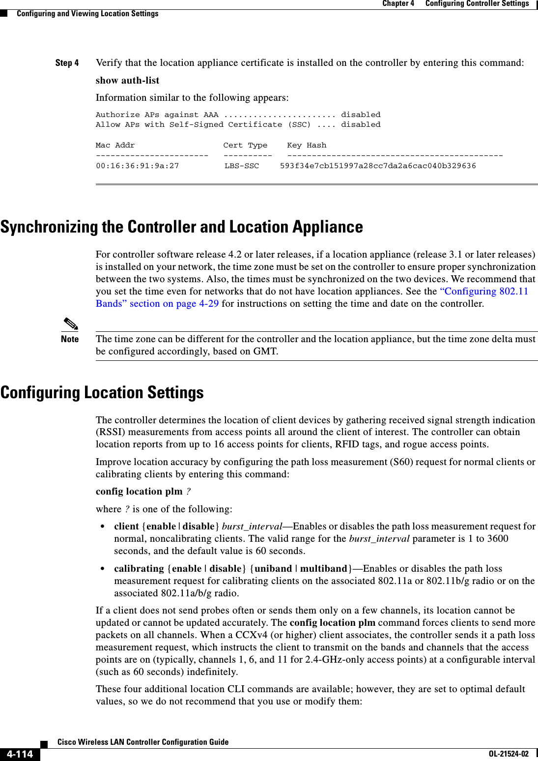
![4-28Cisco Wireless LAN Controller Configuration GuideOL-21524-02Chapter 4 Configuring Controller SettingsInstalling and Configuring Licensesd. In the Password and Confirm Password text boxes, enter the password required in order to view the notification messages at this URL.Step 6 Click Apply to commit your changes.Step 7 Click Save Configuration to save your changes.Using the CLI to Configure the License AgentTo configure the license agent on the controller using the controller CLI, follow these steps:Step 1 Enable the license agent by entering one of these commands: • config license agent default authenticate—Enables the license agent default listener with authentication. • config license agent default authenticate none—Enables the license agent default listener without authentication.Note To disable the license agent default listener, enter the config license agent default disable command. The default value is disabled.Step 2 Specify the maximum number of sessions for the license agent by entering this command:config license agent max-sessions sessionsThe valid range for the sessions parameter is 1 to 25 (inclusive), and the default value is 9.Step 3 Enable the license agent to receive license requests from the CLM and to specify the URL where the license agent receives the requests by entering this command:config license agent listener http {plaintext | encrypt} url authenticate [none] [max-message size] [acl acl]The valid range for the size parameter is 0 to 65535 bytes, and the default value is 0.Note To prevent the license agent from receiving license requests from the CLM, enter the config license agent listener http disable command. The default value is disabled.Step 4 Configure the license agent to send license notifications to the CLM and to specify the URL where the license agent sends the notifications by entering this command:config license agent notify url username passwordNote To prevent the license agent from sending license notifications to the CLM, enter the config license agent notify disable username password command. The default value is disabled.Step 5 Save your changes by entering this command:save configStep 6 See statistics for the license agent’s counters or sessions by entering this command:show license agent {counters | sessions}](https://usermanual.wiki/Cisco-Systems/102075.Cisco-Wireless-LAN-Controller-Configuration-Guide-2/User-Guide-1514962-Page-36.png)
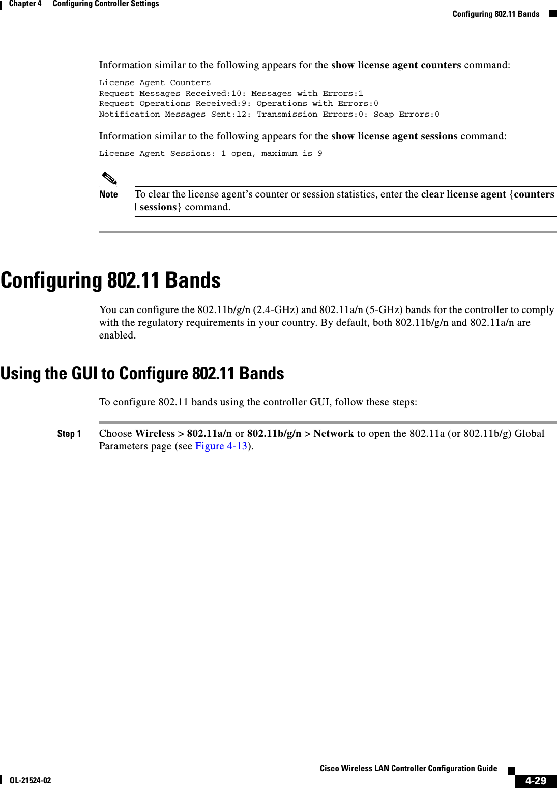
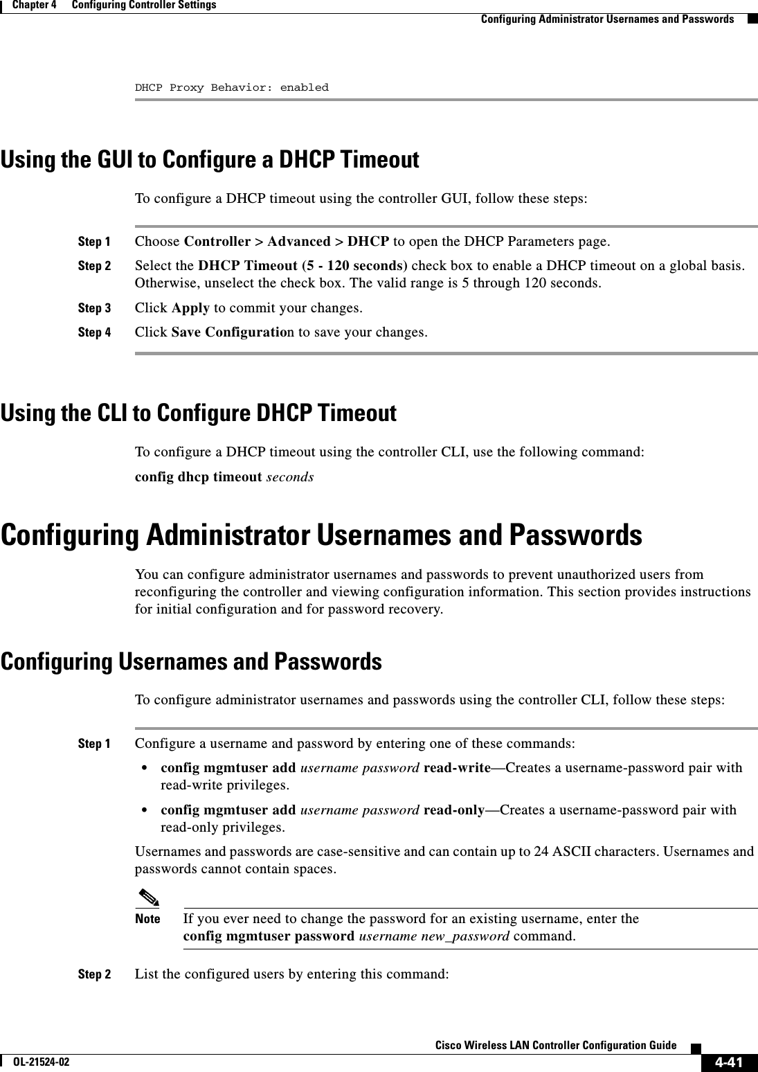
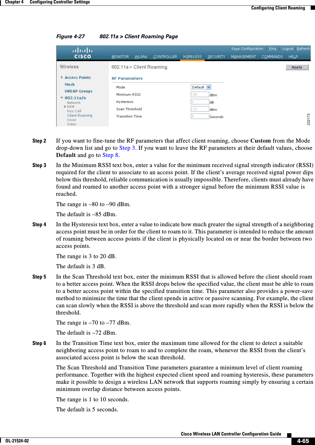
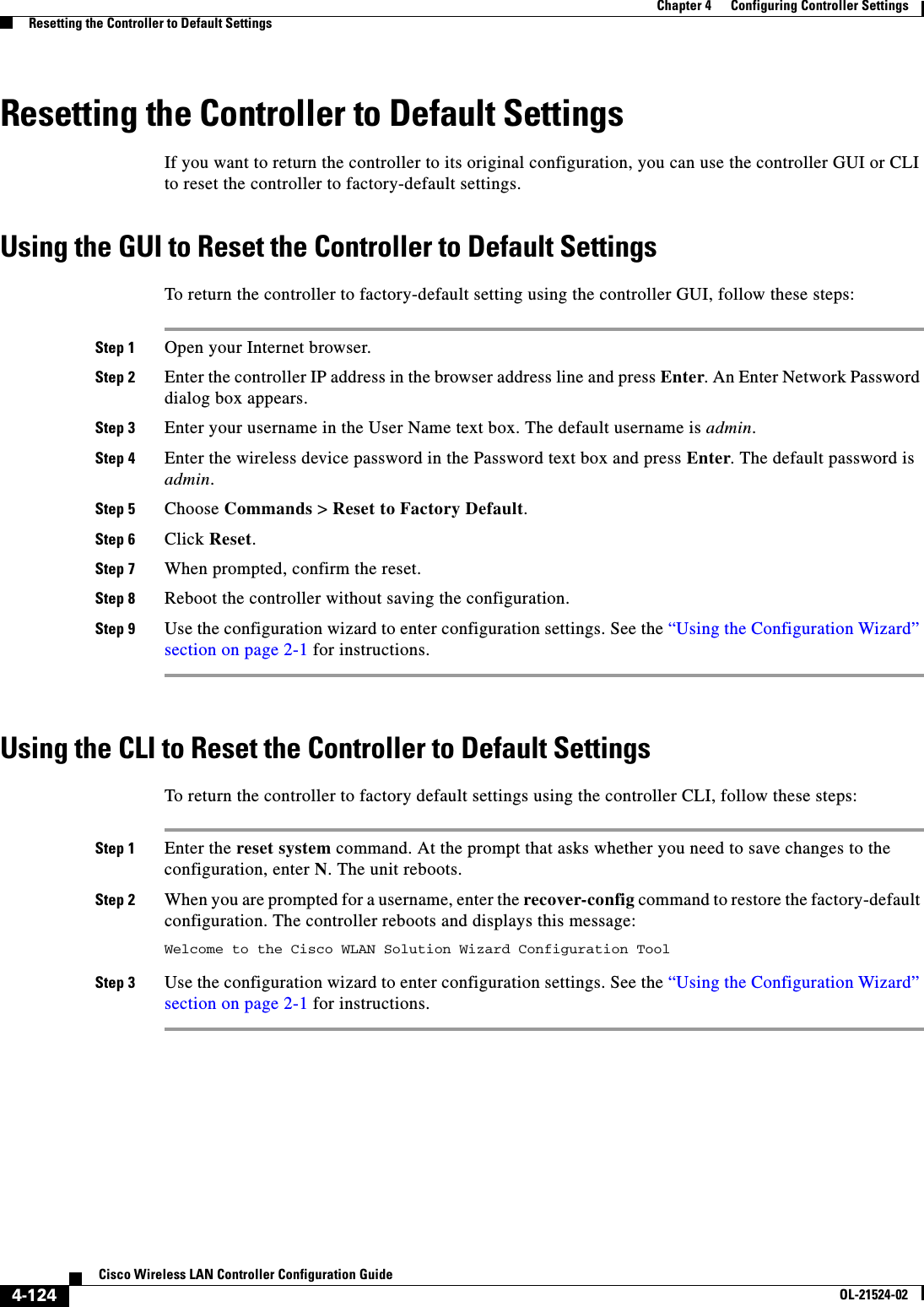
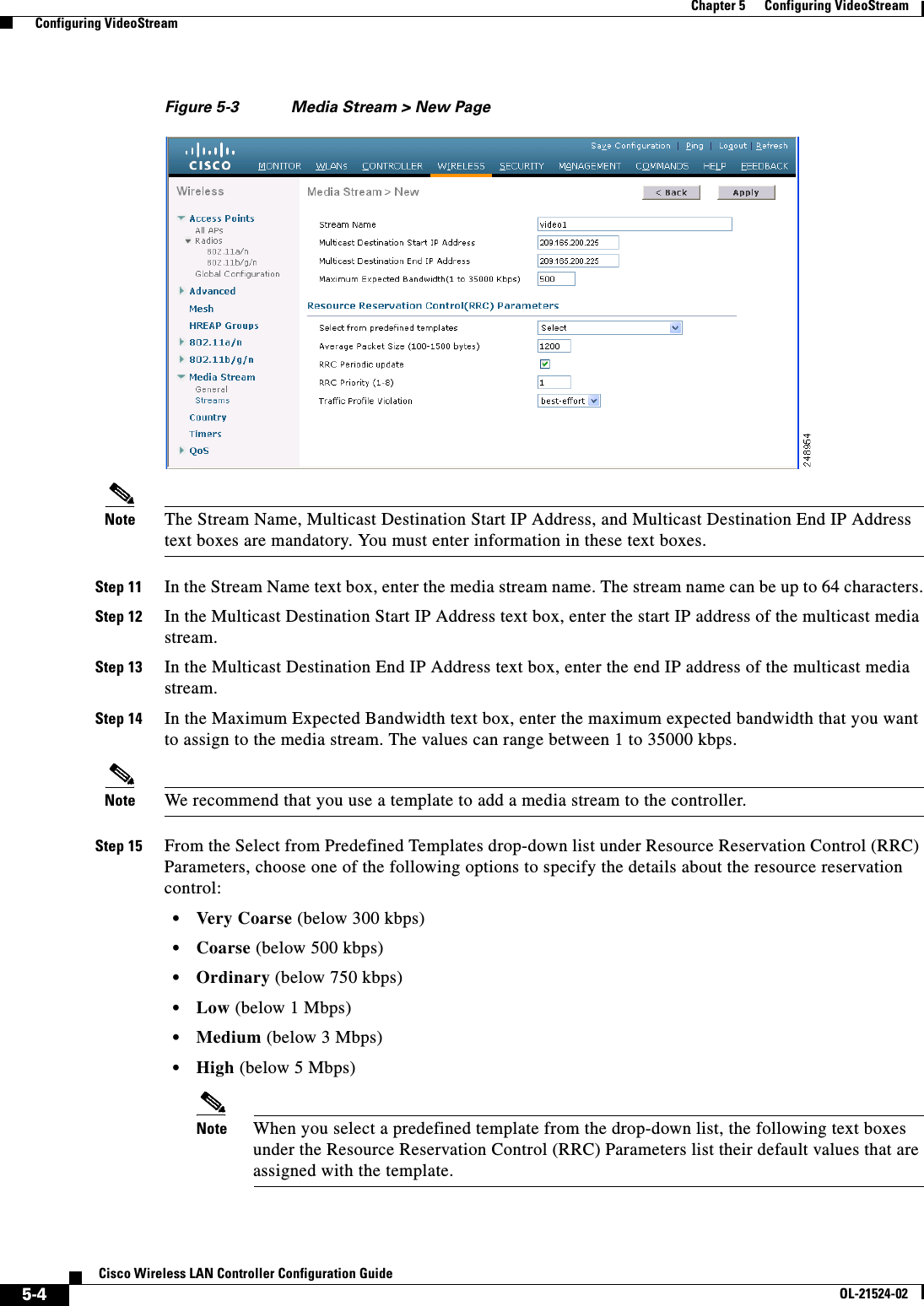
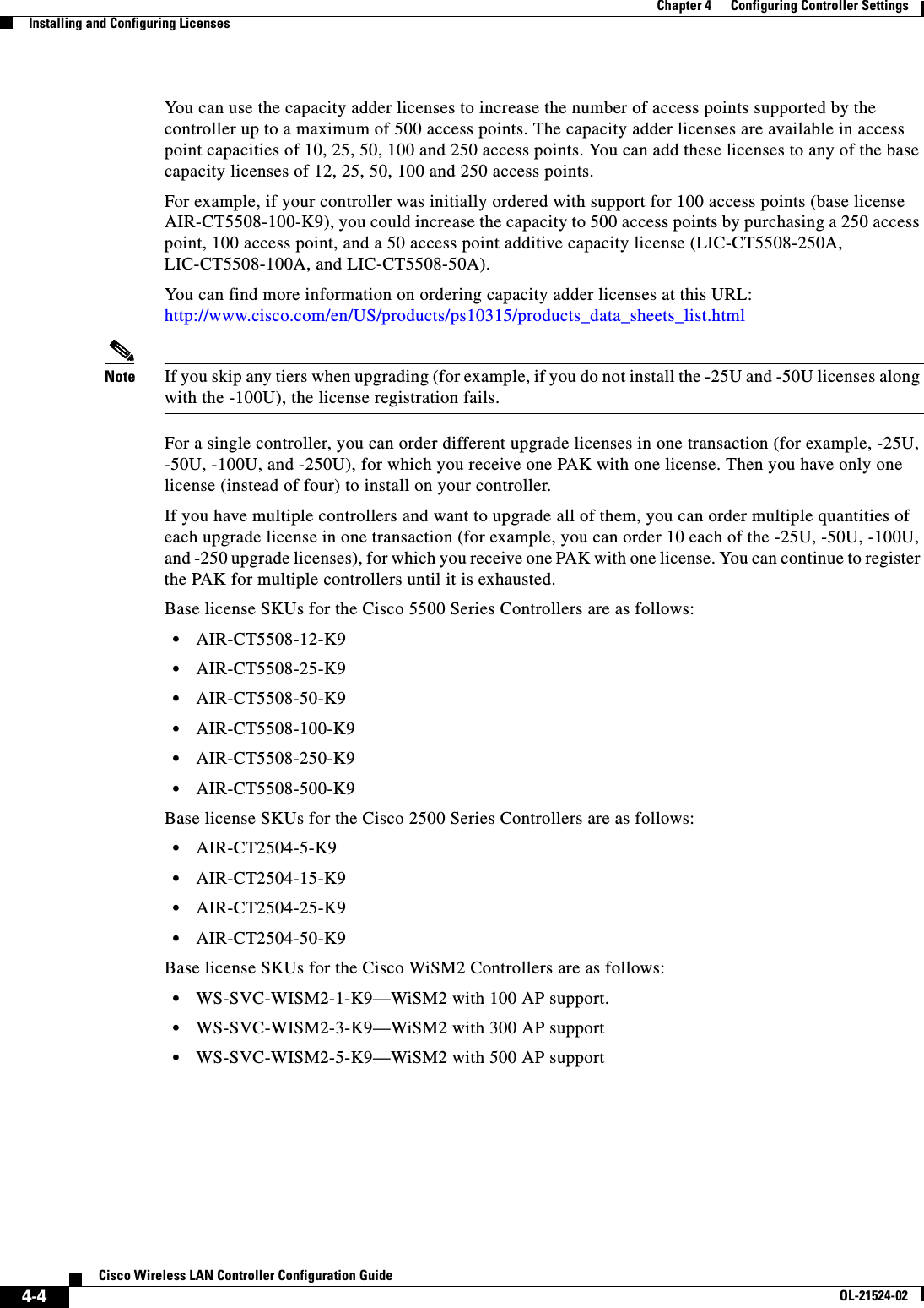
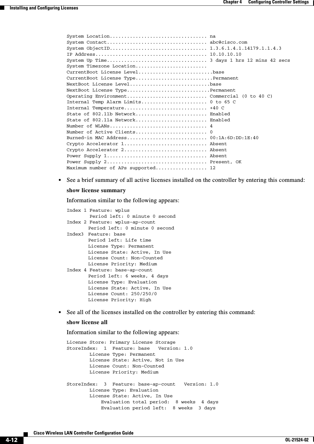
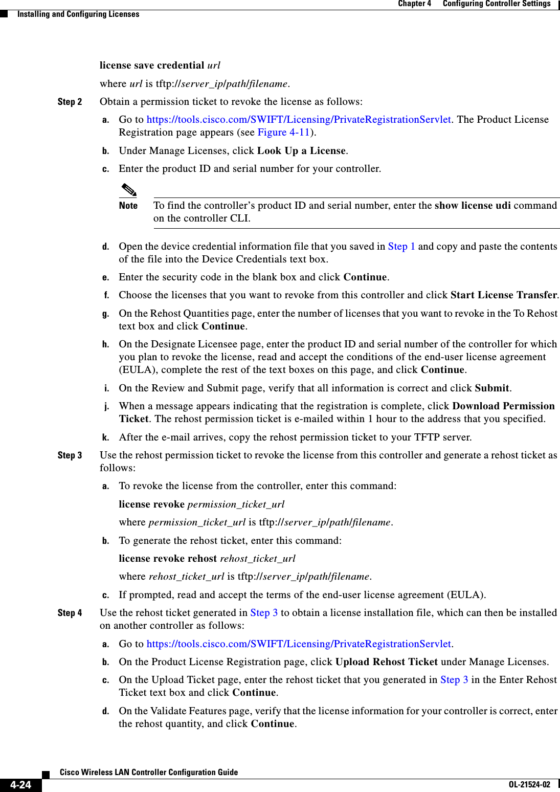
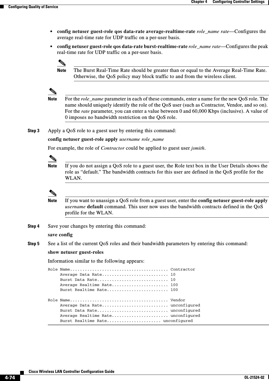
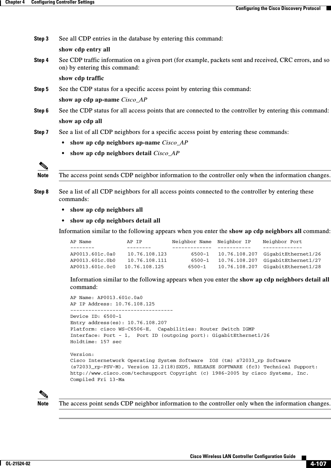
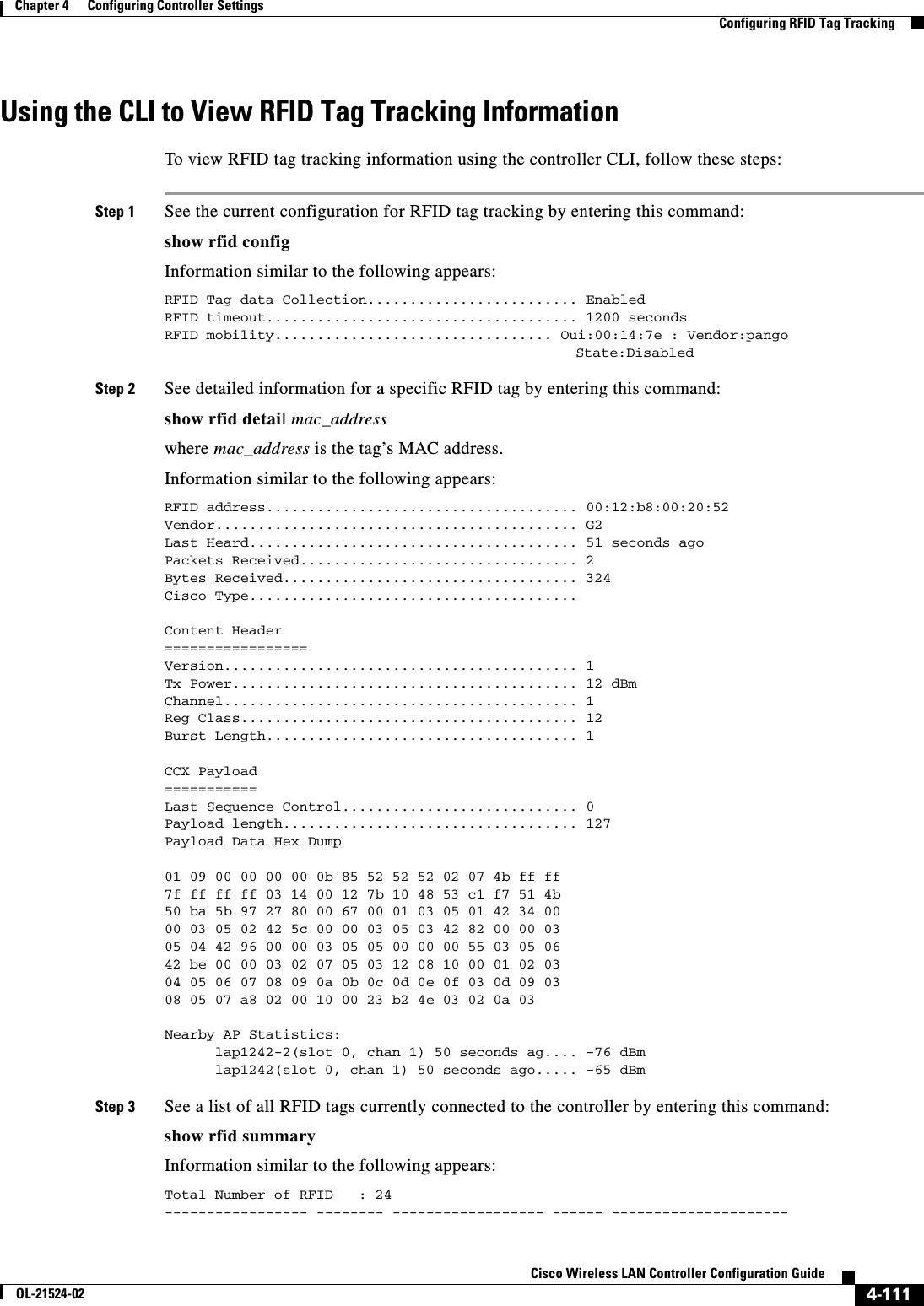
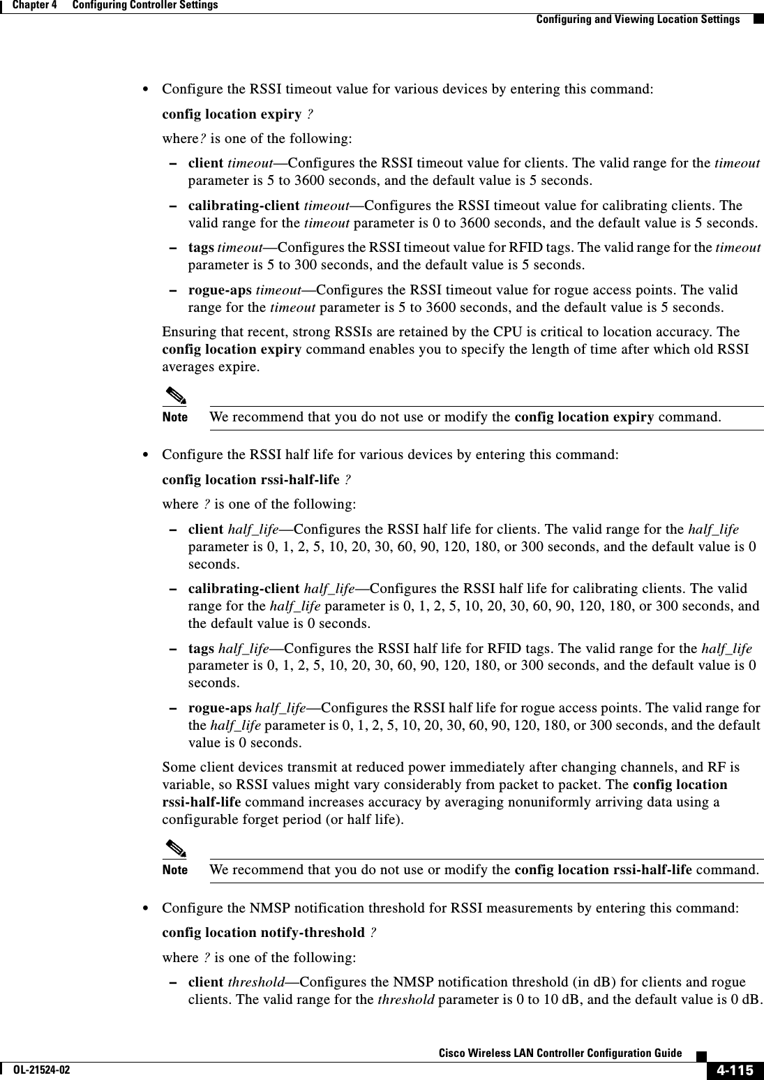
![4-67Cisco Wireless LAN Controller Configuration GuideOL-21524-02Chapter 4 Configuring Controller SettingsConfiguring IP-MAC Address BindingUsing the CLI to Debug CCX Client Roaming IssuesIf you experience any problems with CCX Layer 2 client roaming, enter this command:debug l2roam [detail | error | packet | all] {enable | disable}Configuring IP-MAC Address BindingIn controller software release 5.2 or later releases, the controller enforces strict IP address-to-MAC address binding in client packets. The controller checks the IP address and MAC address in a packet, compares them to the addresses that are registered with the controller, and forwards the packet only if they both match. In previous releases, the controller checks only the MAC address of the client and ignores the IP address.Note If the IP address or MAC address of the packet has been spoofed, the check does not pass, and the controller discards the packet. Spoofed packets can pass through the controller only if both the IP and MAC addresses are spoofed together and changed to that of another valid client on the same controller.To configure IP-MAC address binding using the controller CLI, follow these steps:Step 1 Enable or disable IP-MAC address binding by entering this command:config network ip-mac-binding {enable | disable}The default value is enabled.Note You might want to disable this binding check if you have a routed network behind a workgroup bridge (WGB).Note You must disable this binding check in order to use an access point in sniffer mode if the access point is joined to a Cisco 5500 Series Controller, a Cisco 2100 Series Controller, or a controller network module that runs software release 6.0 or later releases.Step 2 Save your changes by entering this command:save configStep 3 View the status of IP-MAC address binding by entering this command:show network summaryInformation similar to the following appears:RF-Network Name............................. ctrl4404Web Mode.................................... DisableSecure Web Mode............................. EnableSecure Web Mode Cipher-Option High.......... DisableSecure Web Mode Cipher-Option SSLv2......... Enable...IP/MAC Addr Binding Check ............... Enabled ...](https://usermanual.wiki/Cisco-Systems/102075.Cisco-Wireless-LAN-Controller-Configuration-Guide-2/User-Guide-1514962-Page-75.png)

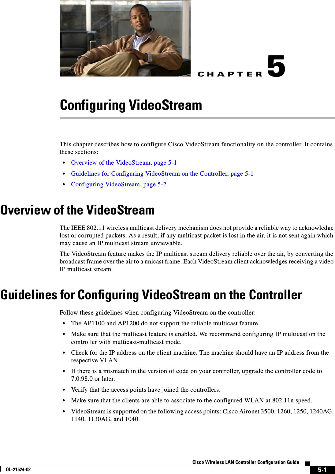
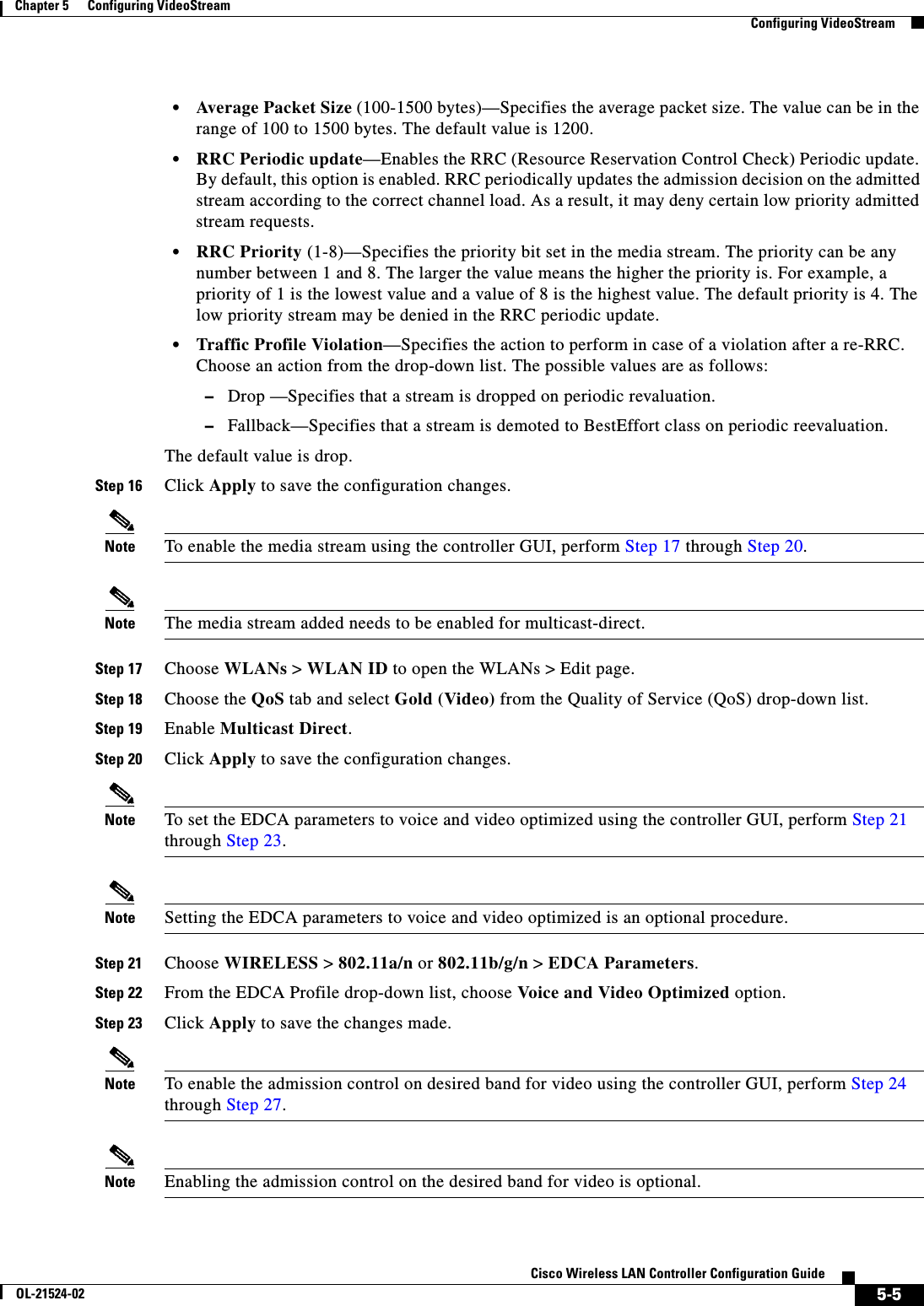
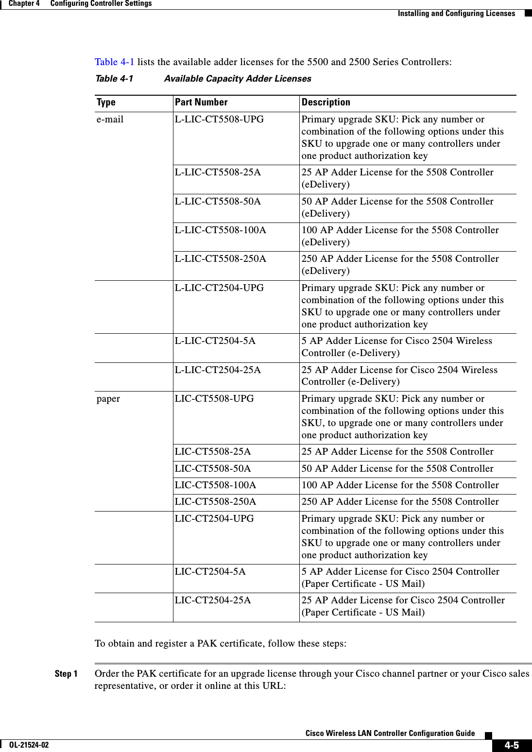
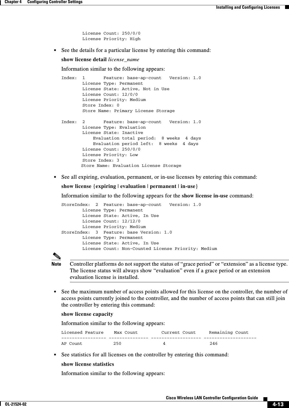
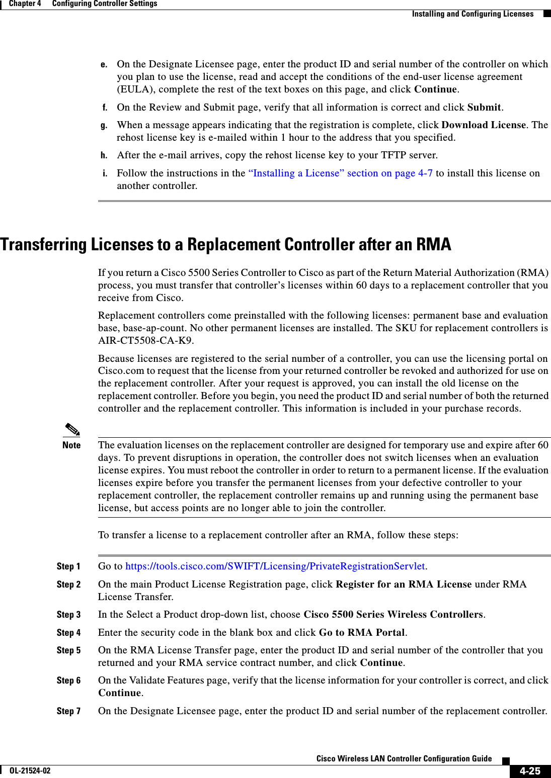
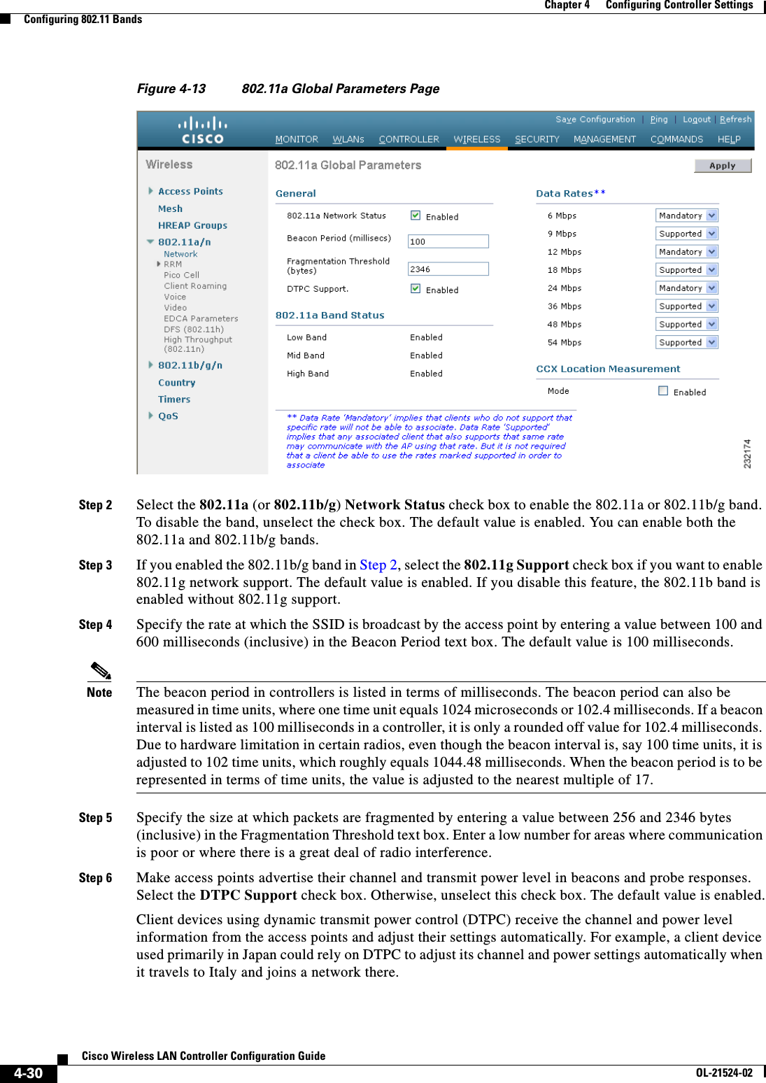
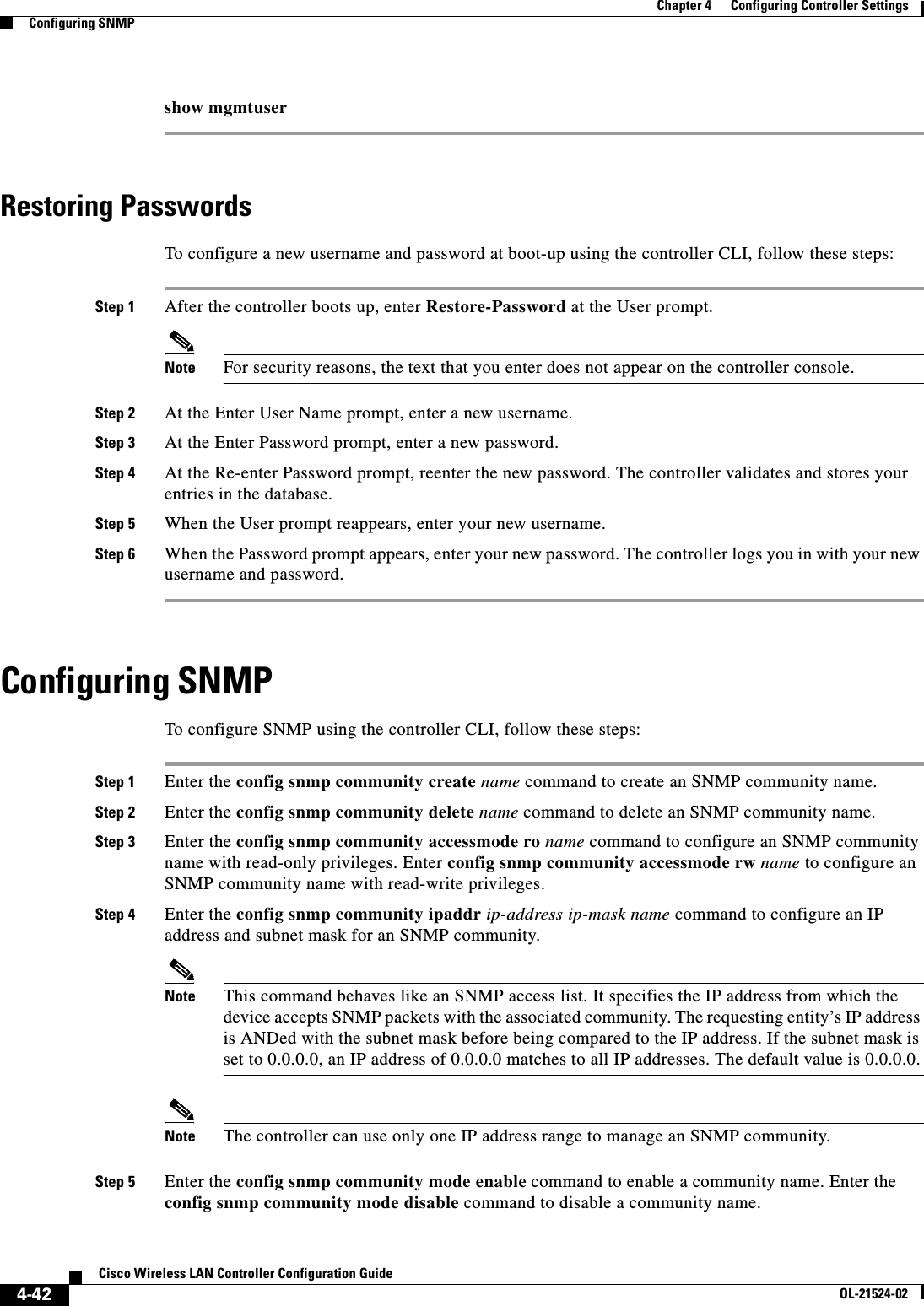
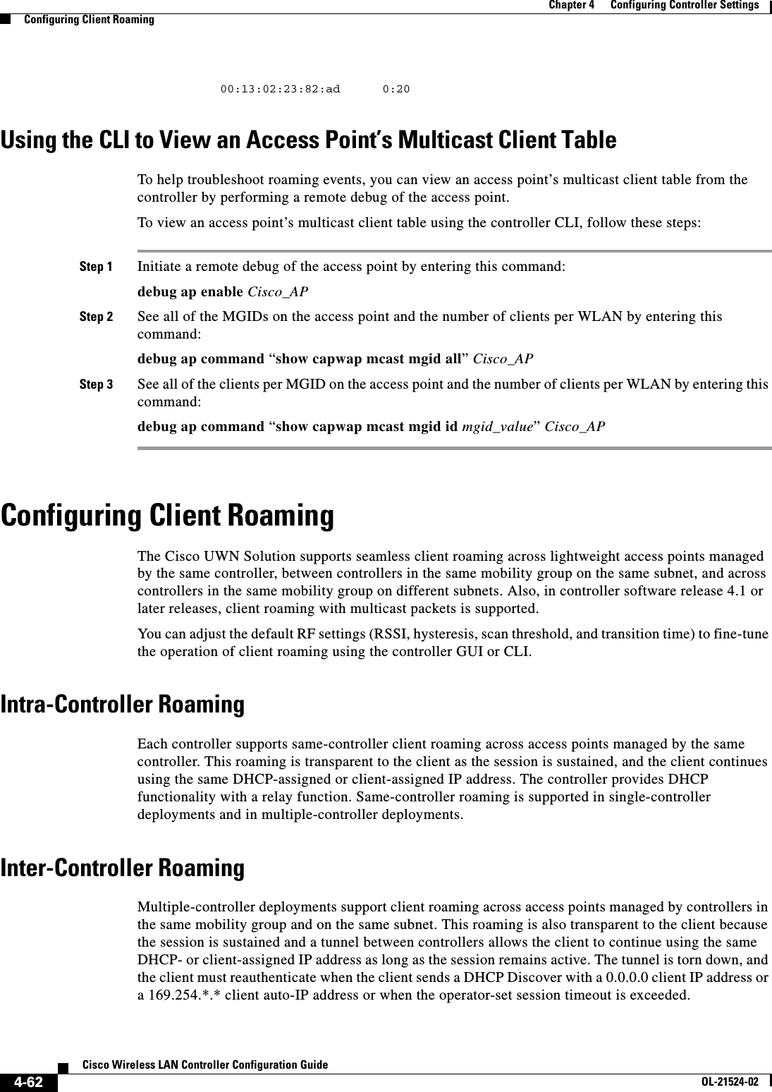
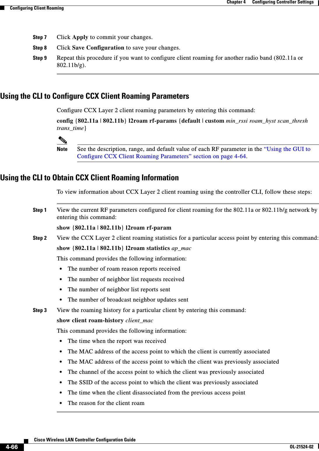
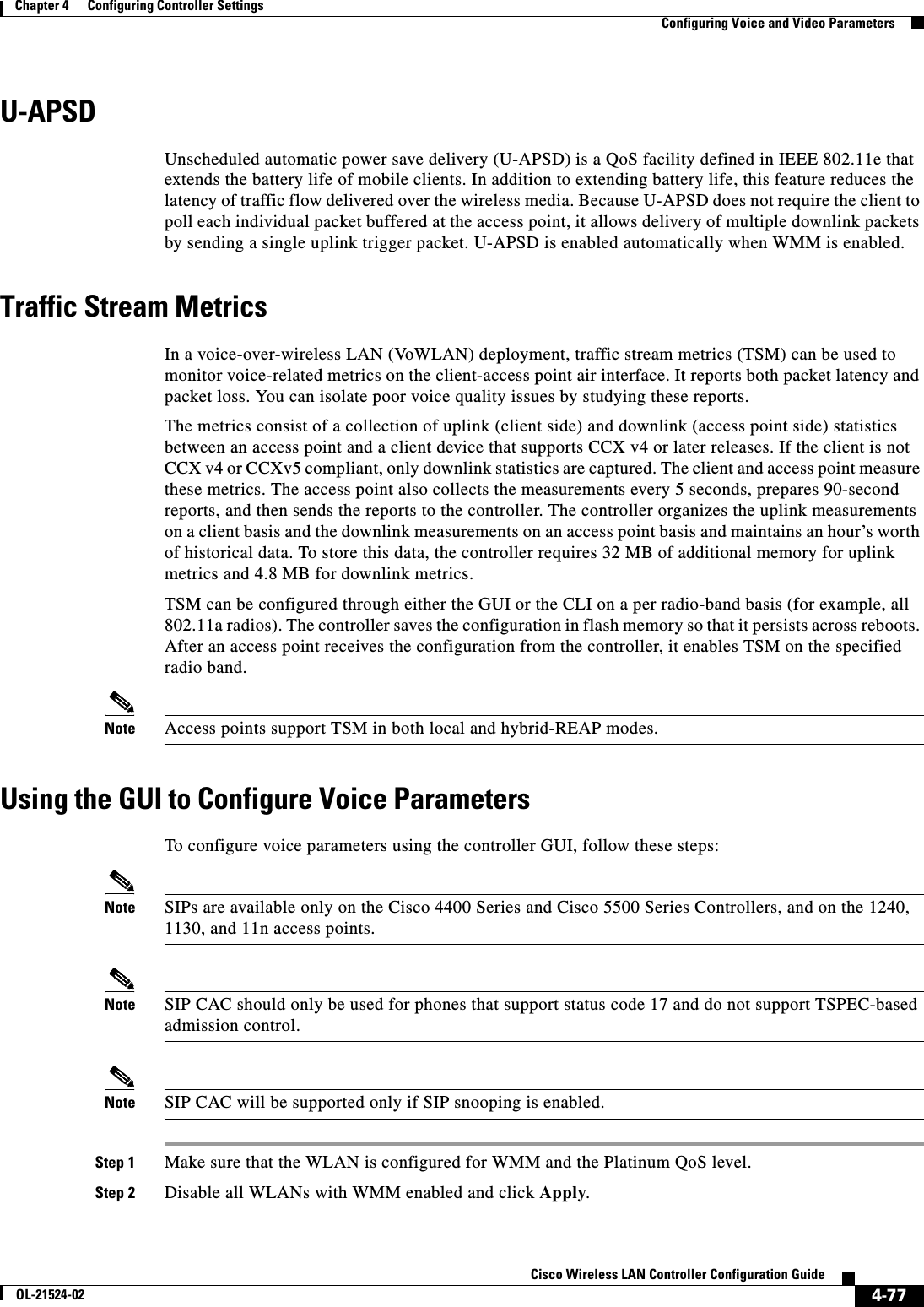
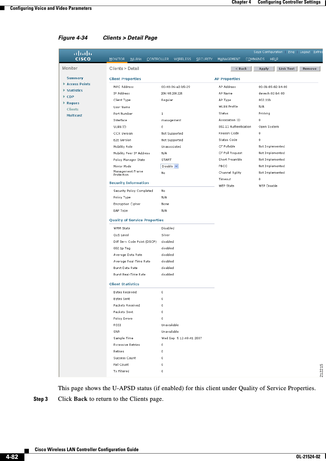
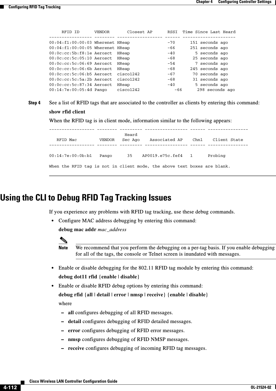
![4-76Cisco Wireless LAN Controller Configuration GuideOL-21524-02Chapter 4 Configuring Controller SettingsConfiguring Voice and Video ParametersIn load-based CAC, the access point continuously measures and updates the utilization of the RF channel (that is, the percentage of bandwidth that has been exhausted), channel interference, and the additional calls that the access point can admit. The access point admits a new call only if the channel has enough unused bandwidth to support that call. By doing so, load-based CAC prevents oversubscription of the channel and maintains QoS under all conditions of WLAN loading and interference.Note Load-based CAC is supported only on lightweight access points. If you disable load-based CAC, the access points start using bandwidth-based CAC.Expedited Bandwidth RequestsThe expedited bandwidth request feature enables CCXv5 clients to indicate the urgency of a WMM traffic specifications (TSPEC) request (for example, an e911 call) to the WLAN. When the controller receives this request, it attempts to facilitate the urgency of the call in any way possible without potentially altering the quality of other TSPEC calls that are in progress.You can apply expedited bandwidth requests to both bandwidth-based and load-based CAC. Expedited bandwidth requests are disabled by default. When this feature is disabled, the controller ignores all expedited requests and processes TSPEC requests as normal TSPEC requests.See Table 4-3 for examples of TSPEC request handling for normal TSPEC requests and expedited bandwidth requests.Note Controller software release 6.0 or later releases support admission control for TSPEC g711-40ms codec type.Note When video ACM is enabled, the controller rejects a video TSPEC if the non-MSDU size in the TSPEC is greater than 149 or the mean data rate is greater than 1 Kbps.Ta b l e 4-3 TSPEC Request Handling Examples CAC ModeReserved bandwidth for voice calls11. For bandwidth-based CAC, the voice call bandwidth usage is per access point and does not take into account co-channel access points. For load-based CAC, the voice call bandwidth usage is measured for the entire channel. Usage22. Bandwidth-based CAC (consumed voice and video bandwidth) or load-based CAC (channel utilization [Pb]).Normal TSPEC RequestTSPEC with Expedited Bandwidth RequestBandwidth-based CAC75% (default setting) Less than 75% Admitted AdmittedBetween 75% and 90% (reserved bandwidth for voice calls exhausted)Rejected AdmittedMore than 90% Rejected RejectedLoad-based CACLess than 75% Admitted AdmittedBetween 75% and 85% (reserved bandwidth for voice calls exhausted)Rejected AdmittedMore than 85% Rejected Rejected](https://usermanual.wiki/Cisco-Systems/102075.Cisco-Wireless-LAN-Controller-Configuration-Guide-2/User-Guide-1514962-Page-84.png)
![4-88Cisco Wireless LAN Controller Configuration GuideOL-21524-02Chapter 4 Configuring Controller SettingsConfiguring Voice and Video ParametersStep 10 Configure the bandwidth that is required per call by entering this command:config {802.11a | 802.11b} cac voice sip bandwidth bandwidth_kbps sample-interval number_msecsStep 11 Reenable all WLANs with WMM enabled by entering this command:config wlan enable wlan_idStep 12 Reenable the radio network by entering this command:config {802.11a | 802.11b} enable networkStep 13 To view the TSM voice metrics, by entering this command:show [802.11a | 802.11b] cu-metrics AP_NameThe command also displays the channel utilization metrics.Step 14 Save your changes by entering this command:save configUsing the CLI to Configure Video Parameters Note Make sure that the“Using the CLI to Configure SIP Based CAC” procedure on page 4-86 are met.To configure video parameters using the controller CLI, follow these steps:Step 1 See all of the WLANs configured on the controller by entering this command:show wlan summaryStep 2 Make sure that the WLAN that you are planning to modify is configured for WMM and the QoS level is set to Gold by entering this command:show wlan wlan_idStep 3 Disable all WLANs with WMM enabled prior to changing the video parameters by entering this command:config wlan disable wlan_idStep 4 Disable the radio network by entering this command:config {802.11a | 802.11b} disable networkStep 5 Save your settings by entering this command:save configStep 6 Enable or disable video CAC for the 802.11a or 802.11b/g network by entering this command:config {802.11a | 802.11b} cac video acm {enable | disable}Step 7 Set the percentage of maximum bandwidth allocated to clients for video applications on the 802.11a or 802.11b/g network by entering this command:config {802.11a | 802.11b} cac video max-bandwidth bandwidthThe bandwidth range is 5 to 85%, and the default value is 5%. However, the maximum RF bandwidth cannot exceed 85% for voice and video. Once the client reaches the value specified, the access point rejects new calls on this network.](https://usermanual.wiki/Cisco-Systems/102075.Cisco-Wireless-LAN-Controller-Configuration-Guide-2/User-Guide-1514962-Page-96.png)
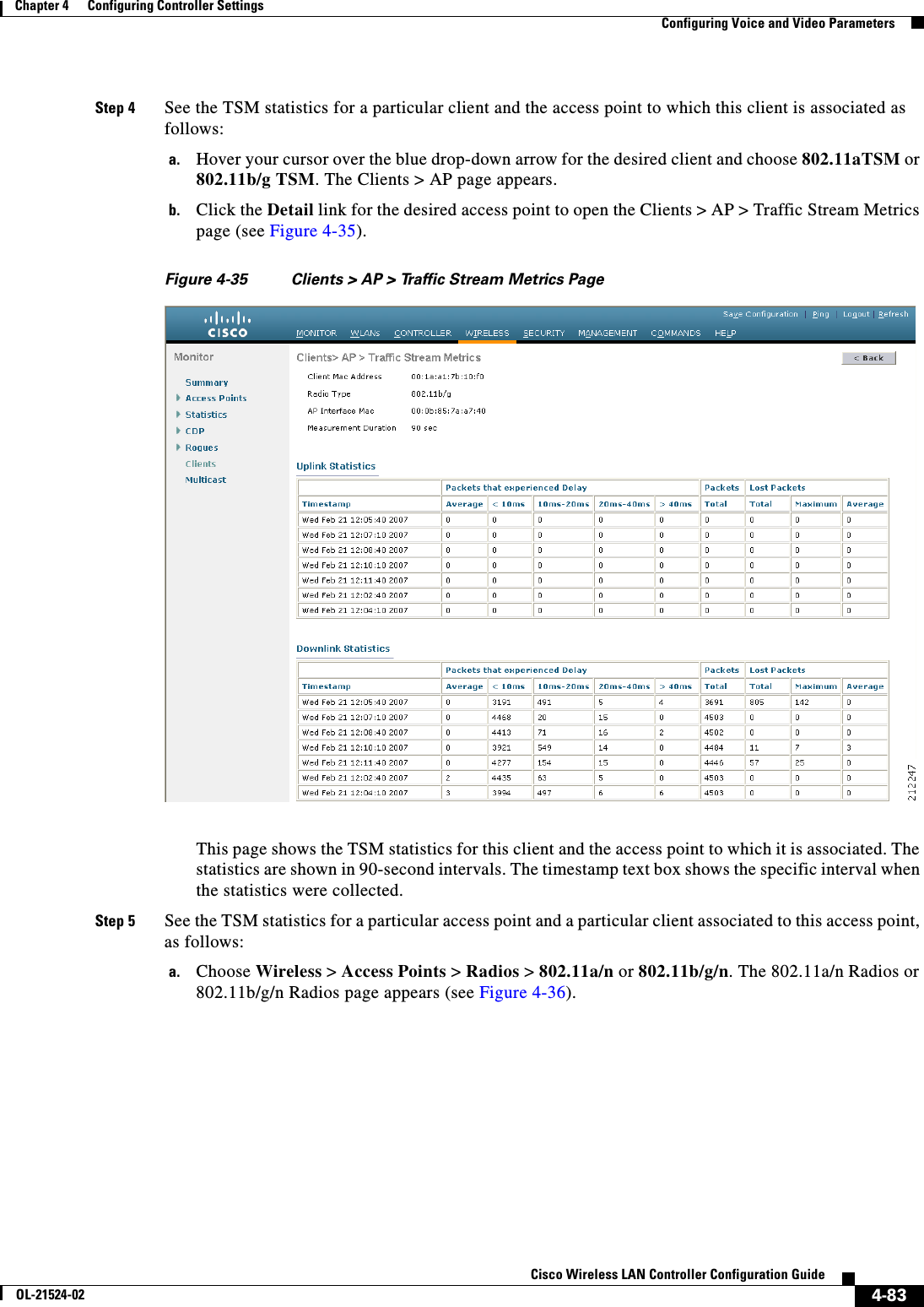
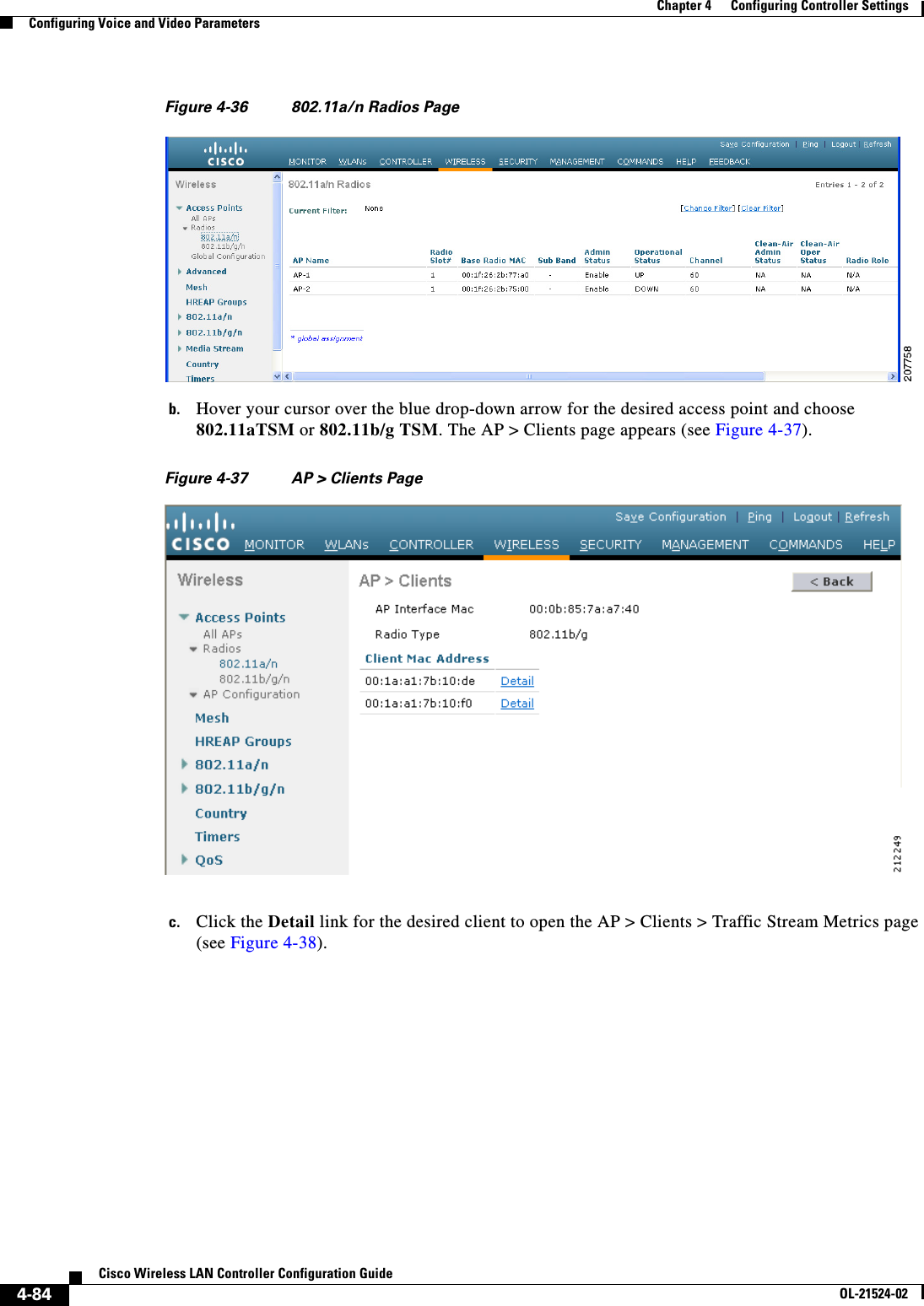
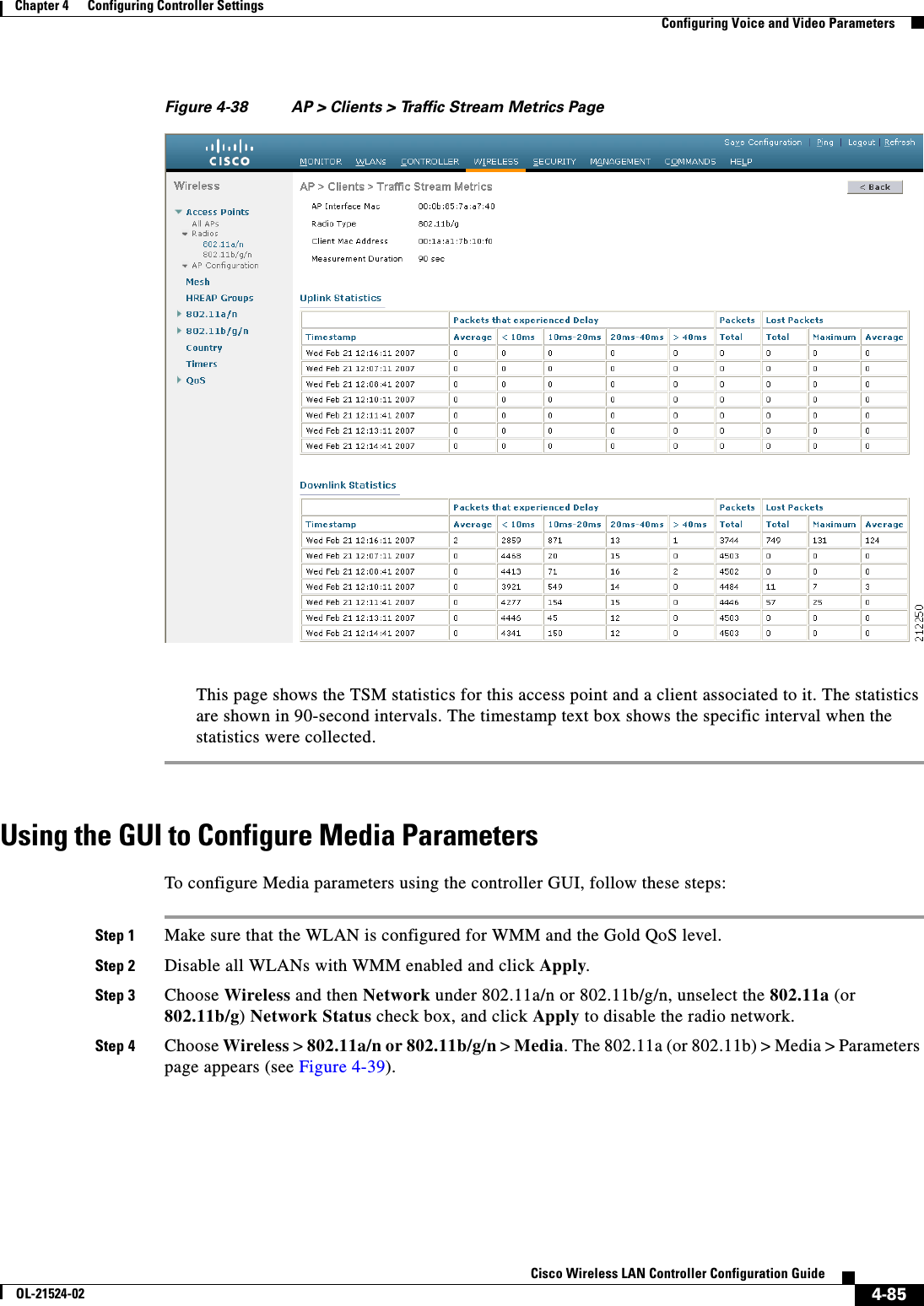
![4-91Cisco Wireless LAN Controller Configuration GuideOL-21524-02Chapter 4 Configuring Controller SettingsConfiguring Voice and Video ParametersThe optional all command shows all clients associated to this access point. Information similar to the following appears:AP Interface Mac: 00:0b:85:01:02:03Client Interface Mac: 00:01:02:03:04:05Measurement Duration: 90 seconds Timestamp 1st Jan 2006, 06:35:80 UpLink Stats ================ Average Delay (5sec intervals)............................35 Delay less than 10 ms.....................................20 Delay bet 10 - 20 ms......................................20 Delay bet 20 - 40 ms......................................20 Delay greater than 40 ms..................................20 Total packet Count.........................................80 Total packet lost count (5sec).............................10 Maximum Lost Packet count(5sec)............................5 Average Lost Packet count(5secs)...........................2 DownLink Stats ================ Average Delay (5sec intervals)............................35 Delay less than 10 ms.....................................20 Delay bet 10 - 20 ms......................................20 Delay bet 20 - 40 ms......................................20 Delay greater than 40 ms..................................20 Total packet Count.........................................80 Total packet lost count (5sec).............................10 Maximum Lost Packet count(5sec)............................5 Average Lost Packet count(5secs)...........................2Note The statistics are shown in 90-second intervals. The timestamp text box shows the specific interval when the statistics were collected.Step 6 Enable or disable debugging for call admission control (CAC) messages, events, or packets by entering this command:debug cac {all | event | packet}{enable | disable}where all configures debugging for all CAC messages, event configures debugging for all CAC events, and packet configures debugging for all CAC packets.Step 7 Use the following command to perform voice diagnostics and to view the debug messages between a maximum of two 802.11 clients:debug client voice-diag {enable | disable} mac-id mac-id2 [verbose]The verbose mode is an optional argument. When the verbose option is used, all debug messages are displayed in the console. You can use this command to monitor a maximum of two 802.11 clients. If one of the clients is a non-WiFi client, only the 802.11 client is monitored for debug messages. Note It is implicitly assumed that the clients being monitored are on call.Note The debug command automatically stops after 60 minutes.Step 8 Use the following commands to view various voice-related parameters:](https://usermanual.wiki/Cisco-Systems/102075.Cisco-Wireless-LAN-Controller-Configuration-Guide-2/User-Guide-1514962-Page-99.png)
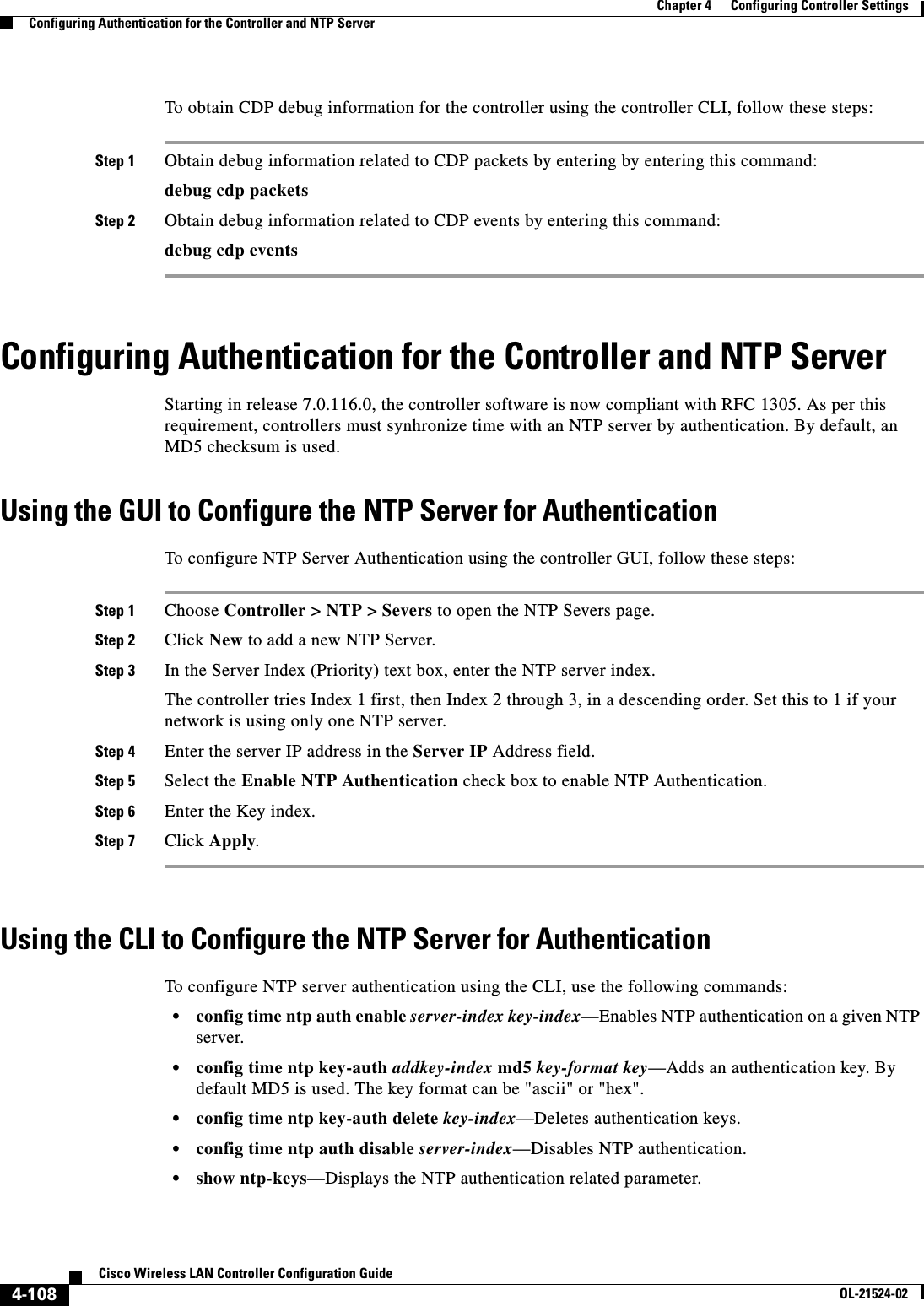
![4-106Cisco Wireless LAN Controller Configuration GuideOL-21524-02Chapter 4 Configuring Controller SettingsConfiguring the Cisco Discovery ProtocolThe range is 10 to 255 seconds, and the default value is 180 seconds.Step 4 Specify the highest CDP version supported on the controller by entering this command:config cdp advertise {v1 | v2}The default value is v1.Step 5 Enable or disable CDP on all access points that are joined to the controller by entering the config ap cdp {enable | disable} all command.The config ap cdp disable all command disables CDP on all access points that are joined to the controller and all access points that join in the future. CDP remains disabled on both current and future access points even after the controller or access point reboots. To enable CDP, enter the config ap cdp enable all command.Note After you enable CDP on all access points joined to the controller, you may disable and then reenable CDP on individual access points using the command in Step 6. After you disable CDP on all access points joined to the controller, you may not enable and then disable CDP on individual access points.Step 6 Enable or disable CDP on a specific access point by entering this command:config ap cdp {enable | disable} Cisco_APStep 7 Configure CDP on a specific or all access points for a specific interface by entering this command:config ap cdp {ethernet | radio} interface_number slot_id {enable | disable} {all | Cisco_AP}Note When you use the config ap cdp command to configure CDP on radio interfaces, a warning message appears indicating that the configuration is applicable only for mesh access points.Step 8 Save your changes by entering this command:save configUsing the CLI to View Cisco Discovery Protocol InformationTo obtain information about CDP neighbors on the controller using the controller CLI, follow these steps:Step 1 See the status of CDP and to view CDP protocol information by entering this command:show cdpStep 2 See a list of all CDP neighbors on all interfaces by entering this command:show cdp neighbors [detail]The optional detail command provides detailed information for the controller’s CDP neighbors.Note This command shows only the CDP neighbors of the controller. It does not show the CDP neighbors of the controller’s associated access points. Additional commands are provided below to show the list of CDP neighbors per access point.](https://usermanual.wiki/Cisco-Systems/102075.Cisco-Wireless-LAN-Controller-Configuration-Guide-2/User-Guide-1514962-Page-114.png)
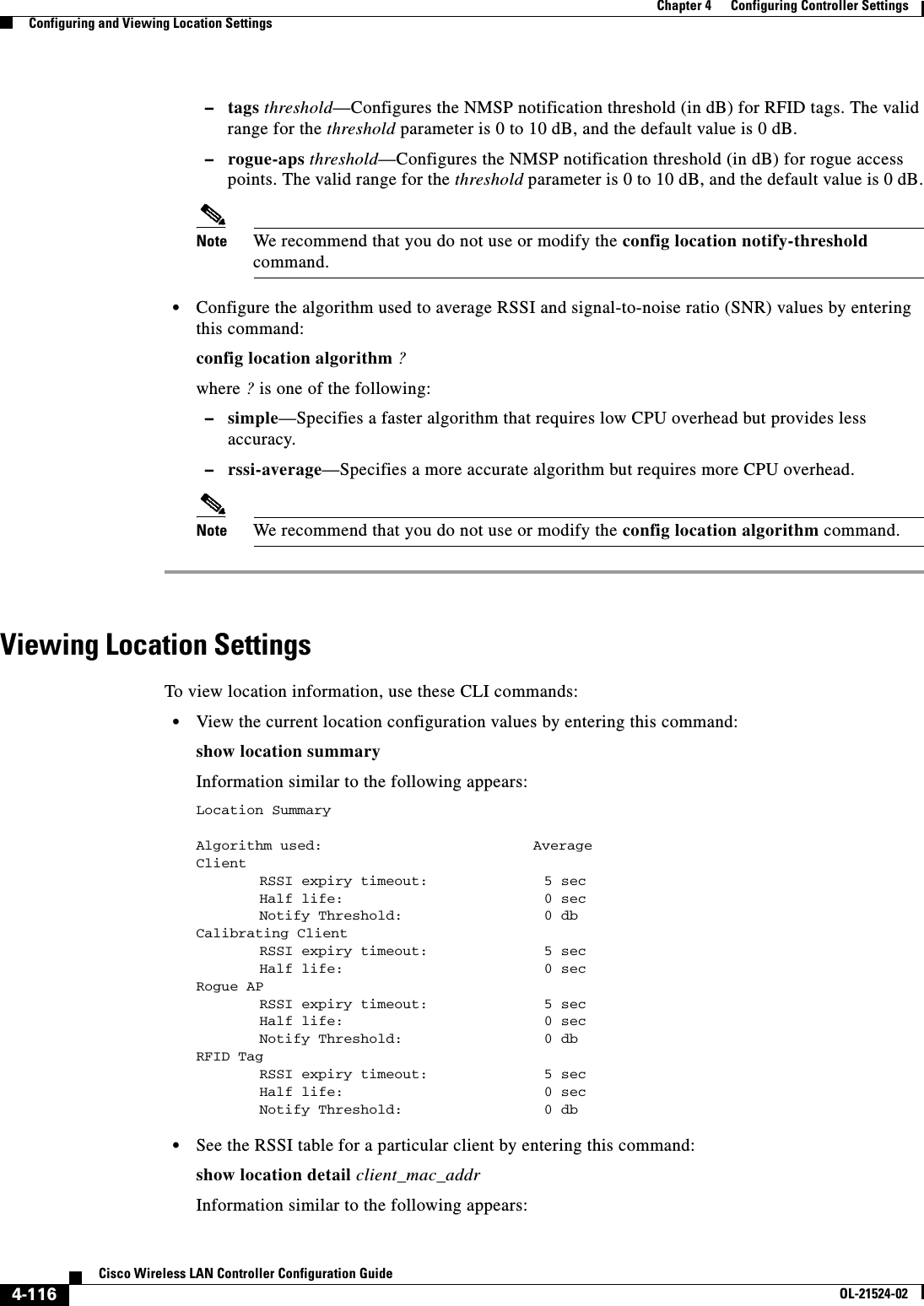
![4-117Cisco Wireless LAN Controller Configuration GuideOL-21524-02Chapter 4 Configuring Controller SettingsConfiguring and Viewing Location Settings... [11] AP 00:00:00:00:00:00 : Slot 0 inUse 0, expired 0, Timestamp (antenna-A 0) (antenna-B 0), band 0 rssi (antenna-A 0) (antenna-B 0), snr 0, acceptable 0[12] AP 00:00:00:00:00:00 : Slot 0 inUse 0, expired 0, Timestamp (antenna-A 0) (antenna-B 0), band 0 rssi (antenna-A 0) (antenna-B 0), snr 0, acceptable 0[13] AP 00:00:00:00:00:00 : Slot 0 inUse 0, expired 0, Timestamp (antenna-A 0) (antenna-B 0), band 0 rssi (antenna-A -1) (antenna-B 0), snr 0, acceptable 0[14] AP 00:00:00:00:00:00 : Slot 0 inUse 0, expired 0, Timestamp (antenna-A 0) (antenna-B 0), band 0 rssi (antenna-A 0) (antenna-B 0), snr 0, acceptable 0[15] AP 00:00:00:00:00:00 : Slot 0 inUse 0, expired 0, Timestamp (antenna-A 0) (antenna-B 0), band 0 rssi (antenna-A 0) (antenna-B 0), snr 0, acceptable 0 • See the location-based RFID statistics by entering this command:show location statistics rfidInformation similar to the following appears:RFID Statistics Database Full : 0 Failed Delete: 0Null Bufhandle: 0 Bad Packet: 0Bad LWAPP Data: 0 Bad LWAPP Encap: 0Off Channel: 0 Bad CCX Version: 0Bad AP Info : 0Above Max RSSI: 0 Below Max RSSI: 0Invalid RSSI: 0 Add RSSI Failed: 0Oldest Expired RSSI: 0 Smallest Overwrite: 0 • Clear the location-based RFID statistics by entering this command:clear location statistics rfid • Clear a specific RFID tag or all of the RFID tags in the entire database by entering this command:clear location rfid {mac_address | all} • See whether location presence (S69) is supported on a client by entering this command:show client detail client_macWhen location presence is supported by a client and enabled on a location appliance, the location appliance can provide the client with its location upon request. Location presence is enabled automatically on CCXv5 clients.Information similar to the following appears:Client MAC Address............................... 00:40:96:b2:a3:44Client Username ................................. N/AAP MAC Address................................... 00:18:74:c7:c0:90Client State..................................... AssociatedWireless LAN Id.................................. 1BSSID............................................ 00:18:74:c7:c0:9fChannel.......................................... 56IP Address....................................... 192.168.10.28Association Id................................... 1Authentication Algorithm......................... Open SystemReason Code...................................... 0Status Code...................................... 0Session Timeout.................................. 0Client CCX version............................... 5Client E2E version............................... No E2E supportDiagnostics Capability........................... SupportedS69 Capability................................... SupportedMirroring........................................ DisabledQoS Level........................................ Silver...](https://usermanual.wiki/Cisco-Systems/102075.Cisco-Wireless-LAN-Controller-Configuration-Guide-2/User-Guide-1514962-Page-125.png)