Electronic Systems Technology ESTEEM195EP BASE STATION TRANSMITTER User Manual CHAPTER 2
Electronic Systems Technology BASE STATION TRANSMITTER CHAPTER 2
Contents
- 1. FCC INFORMATION
- 2. SPECIFICATIONS
- 3. INTERFACE PORTS
- 4. RADIO CONFIGURATION
- 5. SECURITY
- 6. TROUBLESHOOTING
- 7. QUICK START GUIDE 1
- 8. FRONT COVER
- 9. TABLE OF CONTENTS
- 10. INTRODUCTION
- 11. CONFIGURATION DIAGRAMS
- 12. STARTING OUT
- 13. WEB CONFIGURATION MANAGER
- 14. EXAMPLE CONFIGURATIONS 1
- 15. EXAMPLE CONFIGURATIONS 2
- 16. REPEATING FIGURES
- 17. ANTENNA SETUP
- 18. QUICK START GUIDE 2
- 19. QUICK START GUIDE 3
ANTENNA SETUP
CHAPTER 7
ANTENNA SETUPS
Revised: 1 Aug 06 7-1 EST P/N AA107P
ANTENNA AND CABLE CONFIGURATIONS
Warning: Only the tested cable lengths and antennas provided by EST meet the FCC maximum peak output power
requirements. Any other combination of antennas or coax cables is not authorized.
EST offers different types of antennas for indoor, outdoor and mobile configurations.
Part Number: AA191Ep
• Omni-directional, vehicle mount, 5.5dBi gain antenna.
• Mobile vehicle mount applications.
• The AA191Ep antenna must be installed to provide a
separation distance of at least 20 cm from all persons
and must not be co-located or operating in conjunction
with any other antenna or transmitter.
Part Number: AA20DMp
• Omni-directional direct mount antenna, 5 dBi gain.
• Indoor and outdoor applications.
• The AA20DMp antenna must be fixed-mounted on
outdoor permanent structures with a separation
distance of at least 20 cm from all persons during
normal operation and must not be co-located or
operating in conjunction with any other antenna or
transmitter.
Part Number: AA20P
• Omni-directional external pole mount antenna, 9 dBi
gain.
• Outdoor applications.
• Antenna port B is not used in this configuration.
• AA20DP antenna must be fixed-mounted on outdoor
permanent structures with a separation distance of at
least 30 cm from all persons during normal operation
and must not be co-located or operating in conjunction
with any other antenna or transmitter.
Part Number: AA204Ep
• Directional pole mount antenna, 21 dBi gain with 3-ft.
integral feedline and connector.
• Point to point applications only.
• Antenna port B is not used in this configuration.
• The AA204Ep antenna must be fixed-mounted on
outdoor permanent structures with a separation
distance of at least 1.1 meters from all persons during
normal operation and must not be co-located or
operating in conjunction with any other antenna or
transmitter.
Antenna
Port B
Antenna
Port A
Notes:
Antenna Port A is a transmit and receive port for use
in all applications.
Antenna Port B is a receive only port and is used for
dual diversity antennas applications only. This port
is not used for point to point applications.
CHAPTER 7
ANTENNA SETUPS
Revised: 1 Aug 06 7-2 EST P/N AA107P
ANTENNA DIVERSITY
The dual diversity antenna configuration on the ESTeem Model 195Ep allows the radio to operate more efficiently in areas with
high reflections (such as indoors or in a city) and without direct line of sight (LOS) between the antennas. One of the most difficult
conditions to control in a radio system is the effect of a destructive reflected radio signal called mutipathing. Multipathing occurs
when waves emitted by the transmitter travel along a different path and interfere destructively with waves traveling on a direct
line-of-site path. The phenomenon occurs because waves traveling along different paths may be completely out of phase when
they reach the antenna, thereby canceling each other out. The dual diversity antenna configuration places a physical distance
between the antennas where one reflected signal will be out of phase, but the second will be not. The ESTeem Model 195Ep will
sample both antennas and select the best receive signal.
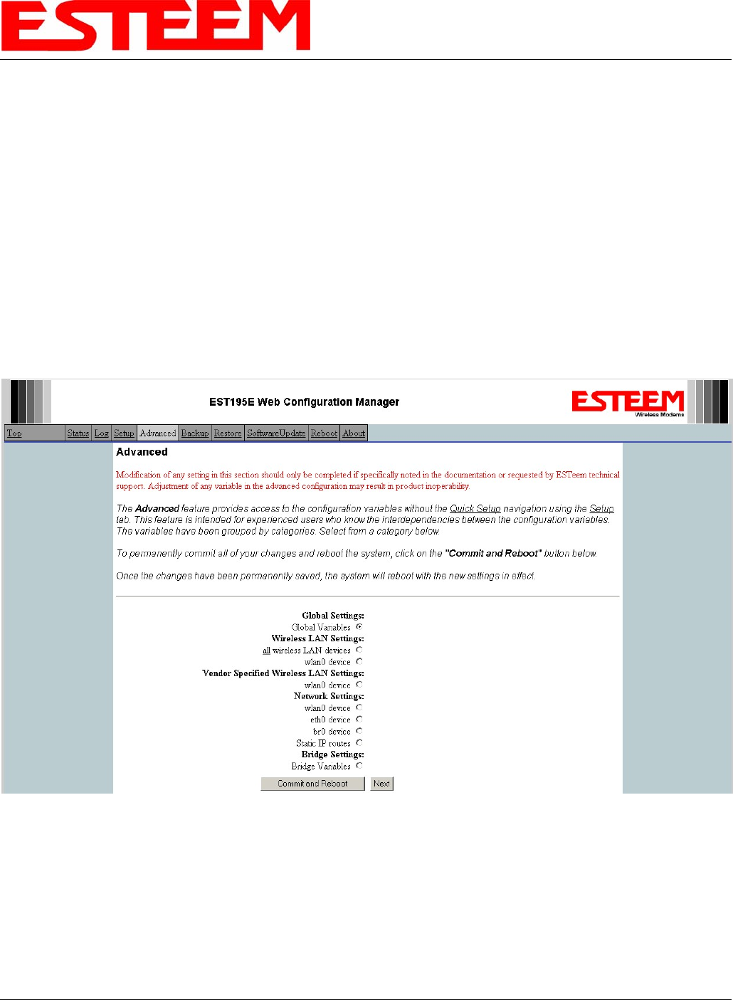
ANTENNA PORT SELECTION
The antenna ports on the Model 195Ep must be configured for either a single receive antenna (external mount antennas) or dual
diversity antenna setup. To access the port configuration open ESTeem Web page using your computer’s Web Browser as per
instructions in Chapter 4. Select Advanced from the menu items and Radio Settings-wlan0 device (Figure 1).
Figure 1: Advanced Settings Menu
CHAPTER 7
ANTENNA SETUPS
Revised: 1 Aug 06 7-3 EST P/N AA107P
Press the next button and Figure 2 will be displayed. The receive antenna is configured by selecting the
wlan0_dot11CurrentRXAntenna drop down (Figure 2) and selecting the receive antenna. A value of 0 = Dual diversity (Both
antenna Ports A & B will be used to receive). A value of 1 = Single receive source (Antenna Port A only).
COAXIAL CABLE ATTENUATION
Figure 2: Receive Antenna Settings Menu
Listed below are representative cable losses in db/100 ft at the 4.9 GHz frequency range:
Feedline Type Attenuation
(dB/100 ft.) @ 4.9 GHz
RG-8 (Solid) >9.9
LMR 600 6.5
3/8" Heliax 8.78
1/2" Heliax 5.49
7/8" Heliax 3.41
Note: A -3 dB loss means you have lost 1/2 of your signal or transmitter power. A +3 dB gain means you have doubled (x2)
your signal or transmitter power.
Example:
A 6 dB antenna will increase the radiated output power of a 1 watt transmitter to 4 watts {times 4 = 3 dB (x2) + 3 dB
(x2)} and increase the received signal strength to receiver times 4
CHAPTER 7
ANTENNA SETUPS
Revised: 1 Aug 06 7-4 EST P/N AA107P
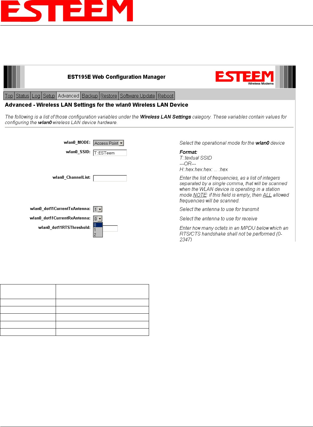
ASSEMBLING THE AA195PM OUTDOOR POLE MOUNTING KIT
The AA195PM mounting kit contains everything required for pole mounting and weatherproofing the ESTeem Model 195Ep for
outdoor installations. The 195Ep with AA195PM mounting kit can be directly mounted to a round pole up to a maximum diameter
of 2” OD. Any mounting structure greater than 2” requires hose clamp strapping run through the Pole Mount Brackets. The
mounting kit requires the following assembly:
1. If you purchased an AA195PM mounting kit with your Model 195Ep, the kit will be packed in the same packing box as the
ESTeem (Figure 1).
Heat Shield
Figure 1: Packet Box Contents
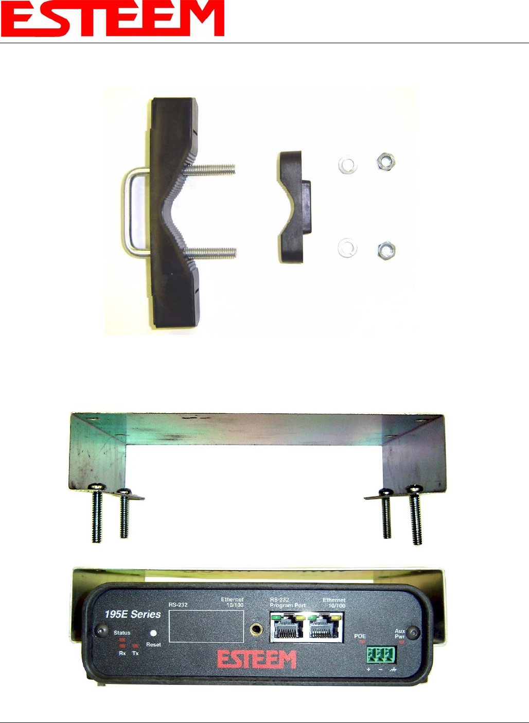
2. Remove and inventory the two (2) Pole Mounting Brackets, one (1) Face Plate Cover, one (1) Heat Shield and (1) AA195PM
Hardware bag from the packing box (Figure 1). Report any missing or damaged items to ESTeem Customer Support (509-
735-9092 Phone) as soon as possible for replacement.
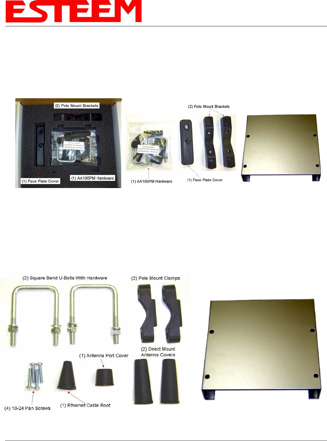
3. Inventory the AA195PM Hardware bag for all the components listed in Figure 2.
Heat Shield
Figure 2: AA195PM Hardware Contents
CHAPTER 7
ANTENNA SETUPS
Revised: 1 Aug 06 7-5 EST P/N AA107P
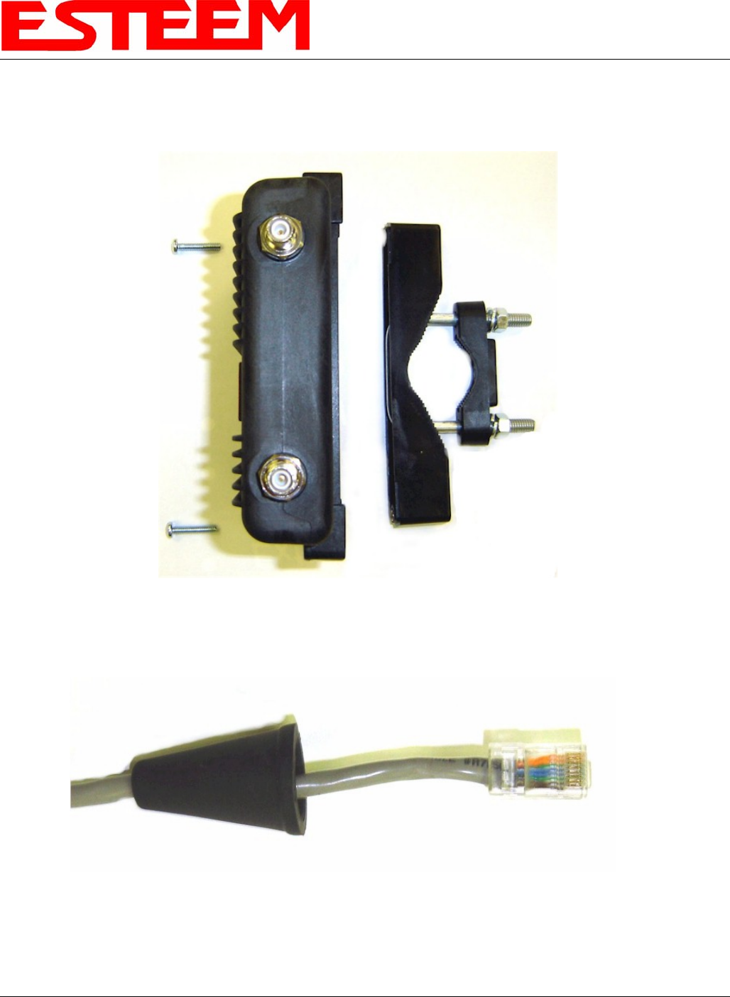
4. Assemble the two Pole Mounting Brackets with the included U-bolts, hardware and Pole Mount Clamps. Reference Figure 3.
Figure 3: Pole Mount Assembly
5. Place the four supplied 10-24 x 1” Phillips Pan Head screws through the mounting holes of the Heat Shield and attach to the
to the top of the ESTeem 195Ep (Figure 4).
Figure 4: Heat Shield Attachment
CHAPTER 7
ANTENNA SETUPS
Revised: 1 Aug 06 7-6 EST P/N AA107P
6. Attach the two Pole Mounting Brackets to the ESTeem Model 195Ep with the 10-24 x 1” Phillips Pan Head screws through
the top of the heat shield. Reference Figure 5 (Heat Shield removed for detail).
Figure 5: Pole Mount Connection to Case
(Heat Shield Removed for Detail)
7. Assemble the outdoor rated CAT-5e Ethernet cable (Not Provided) with the supplied Ethernet Cable Boot (Figure 6).
Figure 6: Ethernet Cable Assembly
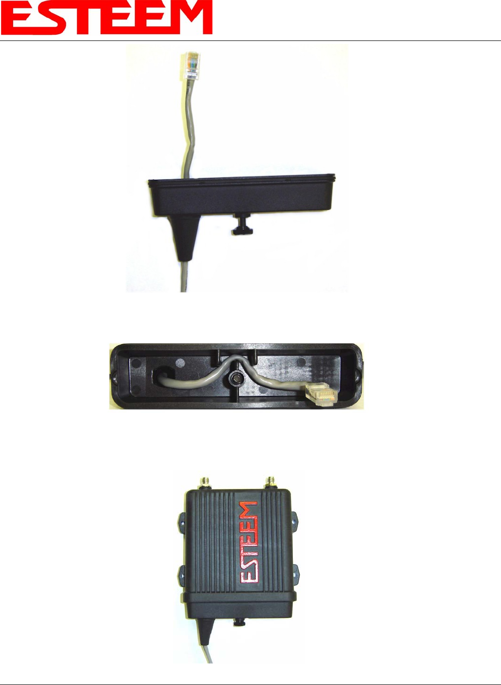
8. Feed the CAT-5e Ethernet connector through the Face Plate Cover and secure the Ethernet Cable Boot to the cover.
Reference Figure 7.
CHAPTER 7
ANTENNA SETUPS
Revised: 1 Aug 06 7-7 EST P/N AA107P
Figure 7: Ethernet Cable Routing
9. Route the CAT-5e Ethernet cable through the molded strain-relief fins in the Face Plate Cover (Figure 8) to secure the cable
and provide strain-relief for the connector.
10. Plug the CAT-5e Ethernet cable to the Model 195Ep’s Ethernet port and secure the Face Plate Cover with the attached thumb
screw. Verify that the weatherproof seal on the Face Plate Cover is sealed against the outer rim of the Model 195Ep.
Reference Figure 9.
Figure 8: Face Plate Cover Strain Relief
Figure 9: Face Plate Cover
CHAPTER 7
ANTENNA SETUPS
Revised: 1 Aug 06 7-8 EST P/N AA107P
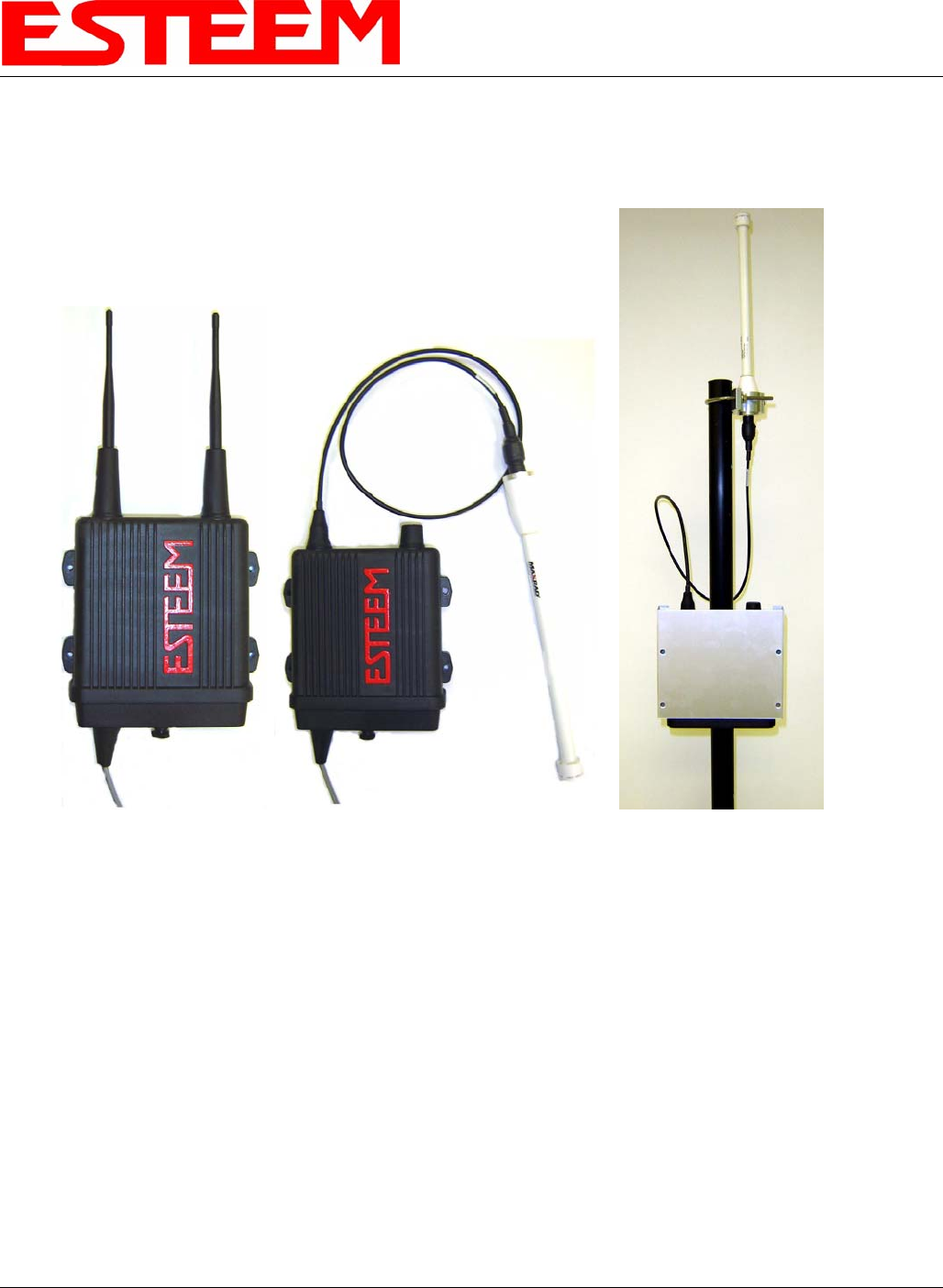
11. Attach the antenna connector boots as show in Figure 10 for either dual attached antennas or external antennas. You are now
ready to mount the ESTeem Model 195Ep.
Figure 11: Completed AA195PM Mounts
Caution: Always mount the 195Ep vertically with the antenna ports on top.
CHAPTER 7
ANTENNA SETUPS
Revised: 1 Aug 06 7-9 EST P/N AA107P
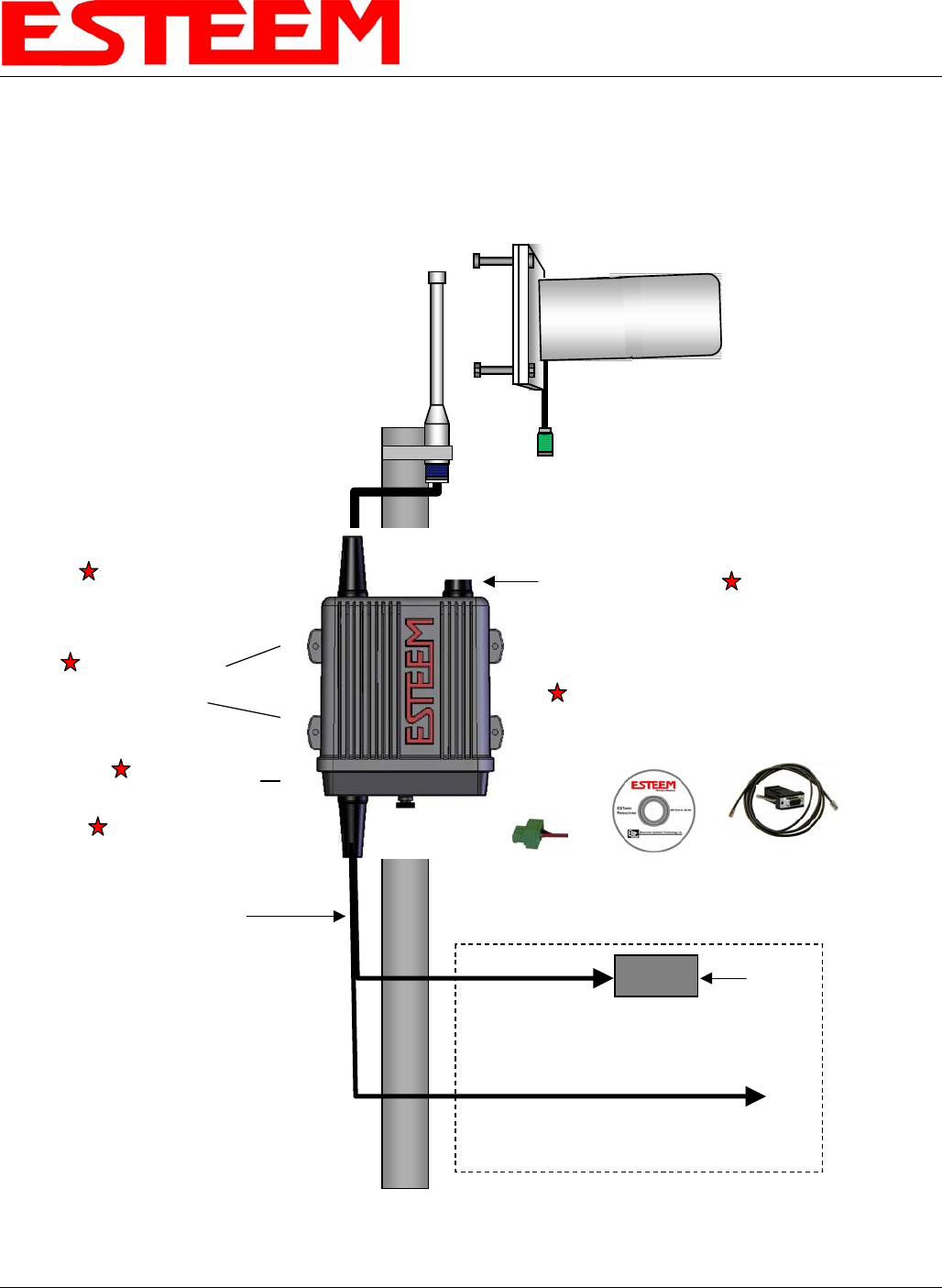
Model195Ep with
External Mount Antennas
Weatherproof
Front Cover
Directional Antenna
(with 3 ft.jumper)
EST P/N AA204Ep
Weatherproof Boot
Direct Pole Mount
Pole Mounting Kit
EST P/N AA195PM
Weatherproof Boot
Weatherproof Boot
In Building
100-250 VAC
50-60 Hz
Pole Mounting
Brackets
(not shown)
Power Supply
EST P/N AA174
Omni-Directional Antenna
(with 3 ft. jumper)
EST P/N AA20Ep
Antenna Port B
(not used)
Antenna Port A
Ethernet/12 VDC
Power Cable
EST P/N AA09.3
(50 ft. maximum)
LAN Interface Cable
ESTeem Resources
EST Part No. AA109
RS-232
Programming
Interface Cable
EST Part No. AA0621
12 VDC
Connector
EST P/N
AA195PP
Caution: Always mount the 195Ep vertically with the antenna ports on top.
CHAPTER 7
ANTENNA SETUPS
Revised: 1 Aug 06 7-10 EST P/N AA107P
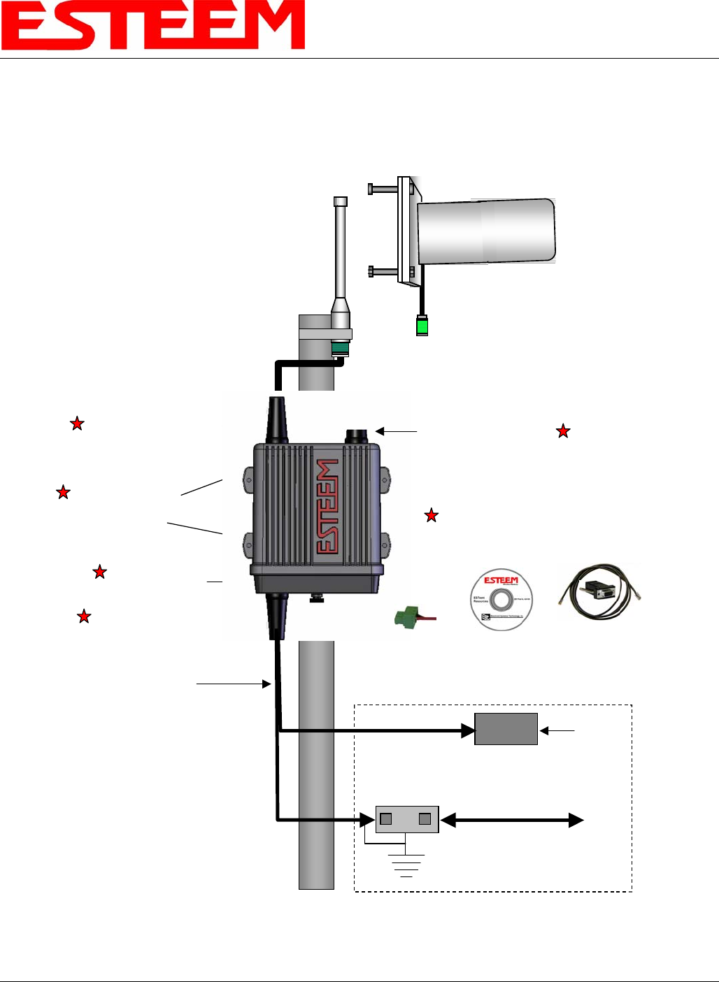
Model195Ep with External Mount
Antennas and Surge Protection
Weatherproof
Front Cover
Directional Antenna
(with 3 ft.jumper)
EST P/N AA204Ep
Weatherproof Boot
Direct Pole Mount
Pole Mounting Kit
EST P/N AA195PM
Weatherproof Boot
Weatherproof Boot
In Building
100-250 VAC
50-60 Hz
Pole Mounting
Brackets
(not shown)
Power Supply
EST P/N AA174
Omni-Directional Antenna
(with 3 ft. jumper)
EST P/N AA20Ep
Antenna Port B
(not used)
Antenna Port A
LAN Interface Cable
Ethernet
CAT 5e Cable
EST P/N: AA09.2
Earth Ground
Ethernet Surge
Protection
EST P/N AA166
ESTeem Resources
EST Part No. AA109
RS-232
Programming
Interface Cable
EST Part No. AA0621
12 VDC
Connector
EST P/N
AA195PP
Ethernet/12 VDC
Power Cable
EST P/N AA09.3
(50 ft. maximum)
Caution: Always mount the 195Ep vertically with the antenna ports on top.
CHAPTER 7
ANTENNA SETUPS
Revised: 1 Aug 06 7-11 EST P/N AA107P
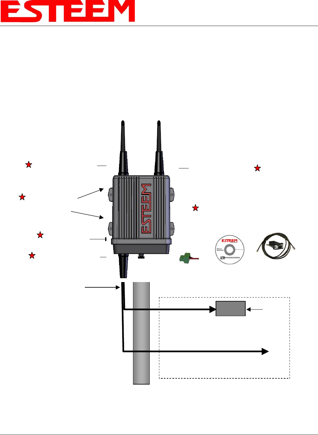
Model 195Ep Series with Direct Mount
Dual Diversity Antennas
Case Mount Omni-Directional
Dual Diversity Antennas
EST P/N AA20DMEp
Weatherproof
Front Cover
Weatherproof Boot
Direct Pole Mount
Pole Mounting Kit
EST P/N AA195PM
Weatherproof Boot
Weatherproof Boot
In Building
100-250 VAC
50-60 Hz
Pole Mounting
Brackets
(not shown)
Power Supply
EST P/N AA174
Antenna Port B
Antenna Port A
LAN Interface Cable
ESTeem Resources
EST Part No. AA109
RS-232
Programming
Interface Cable
EST Part No. AA0621
12 VDC
Connector
EST P/N
AA195PP
Ethernet/12 VDC
Power Cable
EST P/N AA09.3
(50 ft. maximum)
Caution: Always mount the 195Ep vertically with the antenna ports on top
CHAPTER 7
ANTENNA SETUPS
Revised: 1 Aug 06 7-12 EST P/N AA107P
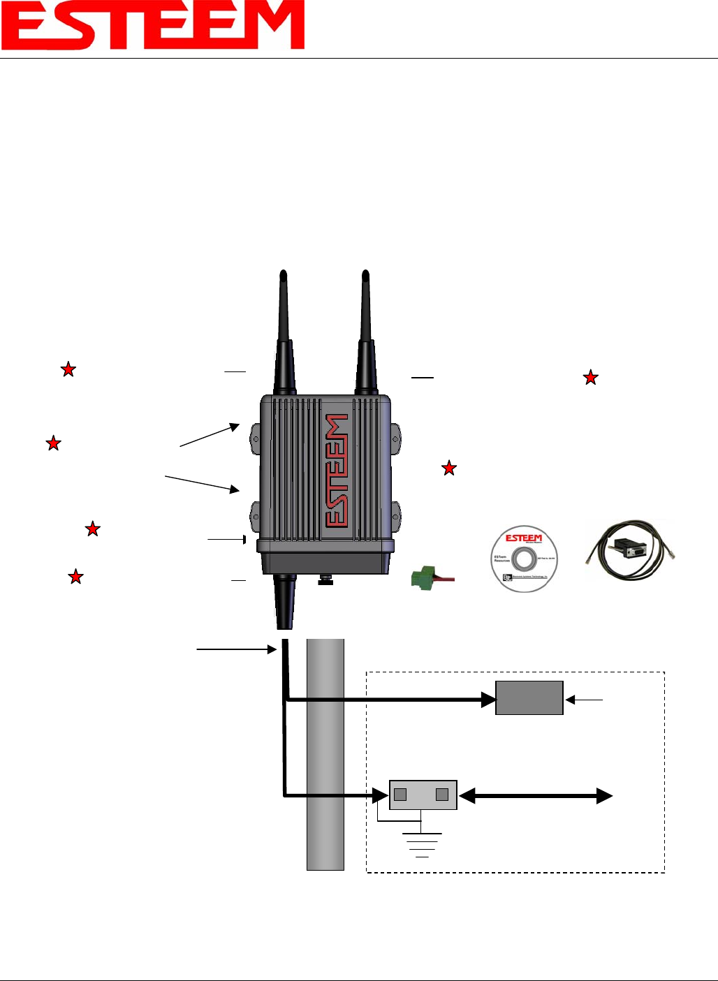
Model 195Ep Series with Direct Mount Dual
Diversity Antennas and Surge Protection
Weatherproof
Front Cover
Weatherproof Boot
Direct Pole Mount
Pole Mounting Kit
EST P/N AA195PM
Weatherproof Boot
Weatherproof Boot
In Building
100-250 VAC
50-60 Hz
Pole Mounting
Brackets
(not shown)
Power Supply
EST P/N AA174
Antenna Port B
Antenna Port A
LAN Interface Cable
Ethernet
CAT 5e Cable
EST P/N: AA09.2
Earth Ground
Ethernet Surge
Protection
EST P/N AA166
ESTeem Resources
EST Part No. AA109
RS-232
Programming
Interface Cable
EST Part No. AA0621
12 VDC
Connector
EST P/N
AA195PP
Case Mount Omni-Directional
Dual Diversity Antennas
EST P/N AA20DMEp
Ethernet/12 VDC
Power Cable
EST P/N AA09.3
(50 ft. maximum)
Caution: Always mount the 195Ep vertically with the antenna ports on top
CHAPTER 7
ANTENNA SETUPS
Revised: 1 Aug 06 7-13 EST P/N AA107P
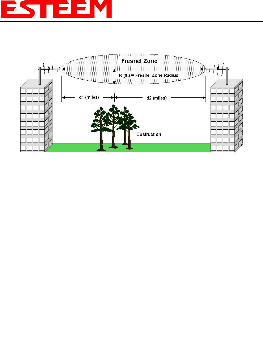
FRESNEL ZONE
The Fresnel zone shows the ellipsoid spread of the radio waves around the visual line-of-sight after they leave the antenna (see
figure above). This area must be clear of obstructions or the signal strength will be reduced due to signal blockage. Typically,
20% Fresnel Zone blockage introduces little signal loss to the link. Beyond 40% blockage, signal loss will become significant.
This calculation is based on a flat earth. It does not take into account the curvature of the earth. It is recommended for RF path
links greater than 7 miles to have a microwave path analysis done that takes the curvature of the earth and the topography of the
terrain into account.
Fresnel Zone Radius = 72.1 SQRT [(d1d2) / (F(d1 + d2)]
Units
Fresnel Zone Radius in feet.
d1 and d2 in statue miles
F in GHz