Electronic Systems Technology ESTEEM195EP BASE STATION TRANSMITTER User Manual CHAPTER 2
Electronic Systems Technology BASE STATION TRANSMITTER CHAPTER 2
Contents
- 1. FCC INFORMATION
- 2. SPECIFICATIONS
- 3. INTERFACE PORTS
- 4. RADIO CONFIGURATION
- 5. SECURITY
- 6. TROUBLESHOOTING
- 7. QUICK START GUIDE 1
- 8. FRONT COVER
- 9. TABLE OF CONTENTS
- 10. INTRODUCTION
- 11. CONFIGURATION DIAGRAMS
- 12. STARTING OUT
- 13. WEB CONFIGURATION MANAGER
- 14. EXAMPLE CONFIGURATIONS 1
- 15. EXAMPLE CONFIGURATIONS 2
- 16. REPEATING FIGURES
- 17. ANTENNA SETUP
- 18. QUICK START GUIDE 2
- 19. QUICK START GUIDE 3
SPECIFICATIONS
APPENDIX B
SPECIFICATIONS
Model 195Eg Specifications
Revised: 16 Jun 06 APX B-1 EST P/N AA107P
LED Indicators
Power On/Off Receiver On/Off
Carrier Detect On/Off Transmitter On/Off
Link Status On/Off
I/O Connectors
Ethernet 10/100Base T RJ-45
RS-232C Programming Port RJ-45
Dual Antenna input/Outputs TNC Reverse Female
Direct Input Power Header Screw Connector
Transmiter
Frequency of Operation 4.960 & 4.980 GHz
Software Selectable with two Channels
RF Data Rates 1,2,5.5,6,9, & 11 Mbps Fixed or Auto Scaling
DSSS/CCK Modulation
Tx Output Power 2 Watts (peak) / 1 watt (average)
RF Output Impedance 50 ohms
Receiver
Rx Sensitivity -85 dBm @11 Mbps to –92 dBm @ 1 Mbps
Frame Error Rate <10%
Power
Power Connector on Unit 10 to 16 VDC
Receive 320 ma @ 12 VDC
Transmit 1500 ma @ 12 VDC
Case
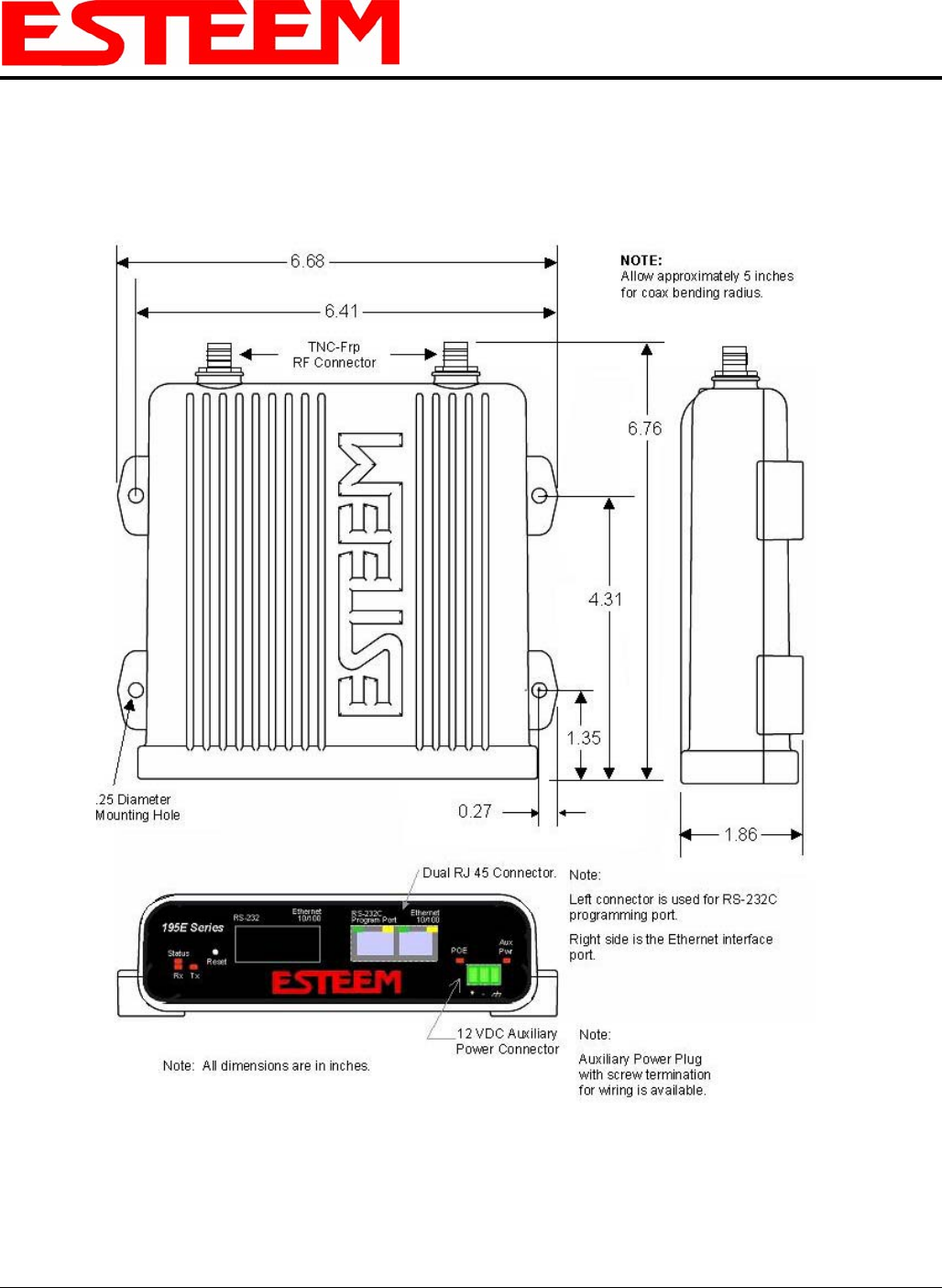
Dimensions 1.9 in. H x 6.7 in. W x 6.2 in. L
Weight 1.25 lbs.
Outdoor Pole Mounting Kit Optional, EST P/N 195PM
Other
Warranty 1 Year
Temperature Range -30° to +60° C
Humidity 95% Non-condensing
FCC Type Acceptance Pending Type Acceptance
Specifications Subject to Change Without Notice
APPENDIX B
SPECIFICATIONS
Model 195Eg Case Specifications
Revised: 16 Jun 06 APX B-2 EST P/N AA107P
APPENDIX B
SPECIFICATIONS
Antenna Specifications
Revised: 16 Jun 06 APX B-3 EST P/N AA107P
Model No: AA191Ep
Antenna Type: Omni-Directional, Vehicle Mount
Applications: Mobile
Model AA191Ep
Frequency: 4.9-5.0 GHz
Polarization: Vertical Caution
Omni-directional antenna
should not be located within
20 cm of personnel.
Impedance: 50 ohms
Gain: 5.5 dBi
VSWR: < 1.5
Front to Back Ratio: n/a
Horizontal Beamwidth: n/a
Vertical Beamwidth: n/a
Antenna Material: Black Radome
Mounting Hardware: Base Included
Antenna Connector: TNC-R Male
Antenna Envelope: 12 in. length by 1.75 in width
Weight: .08 lbs.
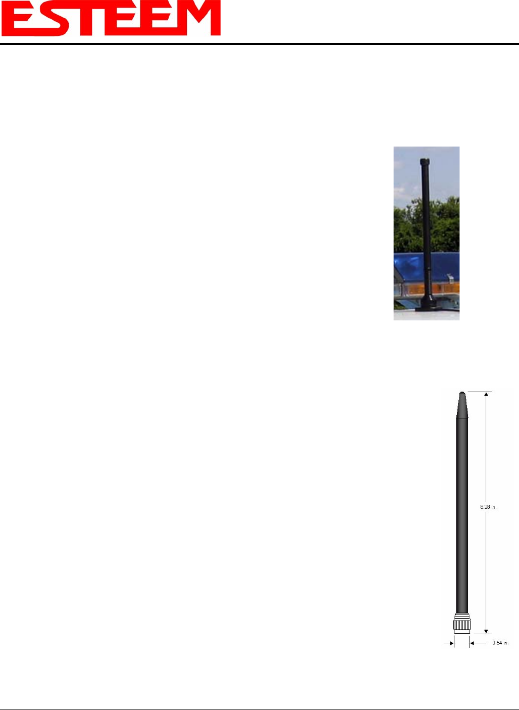
Model: AA20DMEp
Model AA20DMEp
Applications: Model 195Ep direct case mount
Antenna Type: Omni-Directional, Sleeve dipole
Frequency: 4.9-5.0 GHz Caution
Omni-directional antenna
should not be located within
20 cm of personnel.
Polarization: Vertical
Impedance: 50 ohms
Gain: 5.5 dBi (3.5 dBd)
VSWR: < 2:1
Power: 10 W
Front To Back Ratio: n/a
Horizontal Beamwidth: n/a
Vertical Beamwidth: n/a
Antenna Material: Polyurethane Plastic Radome
Recommended Mounting Hardware: n/a
Antenna Connector: TNC-R Male
Flexibility: +/- 20 °
Antenna Envelope: 8.28 in. length by .54 in. width
Temperature: -40 to +70 C°
Weight: 33 grams
APPENDIX B
SPECIFICATIONS
Antenna Specifications
Revised: 16 Jun 06 APX B-4 EST P/N AA107P
Mounting Bracket
Model AA20Eg
Caution
To comply with the FCC
exposure compliance
requirements, a separation
distance of at least 20 cm
must be maintained between
the antenna and all persons.
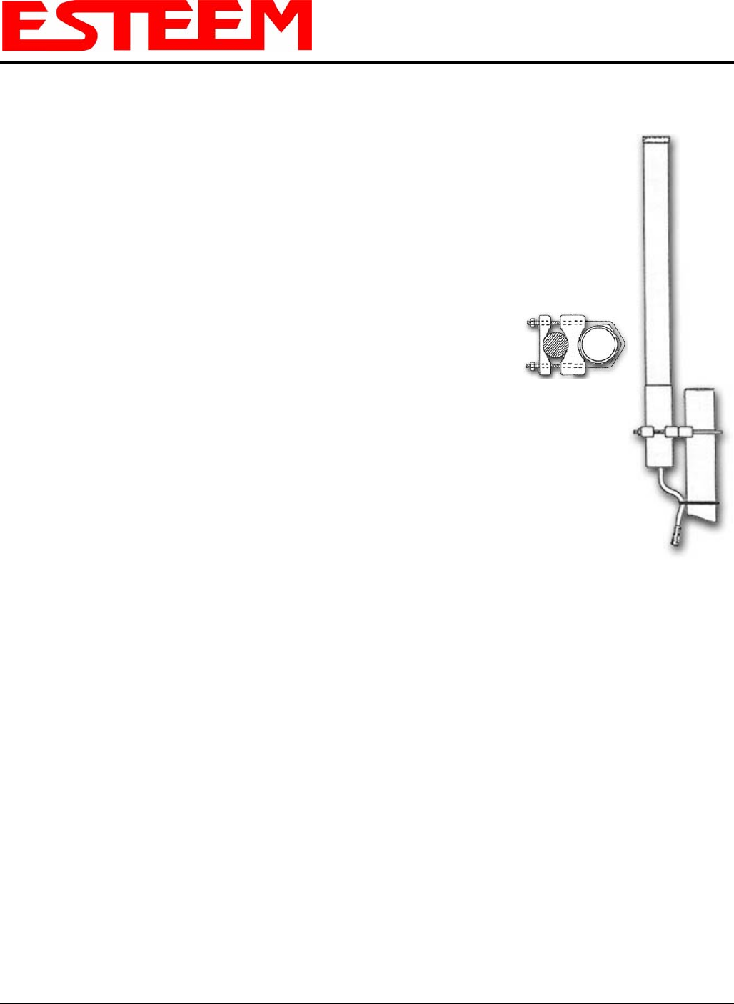
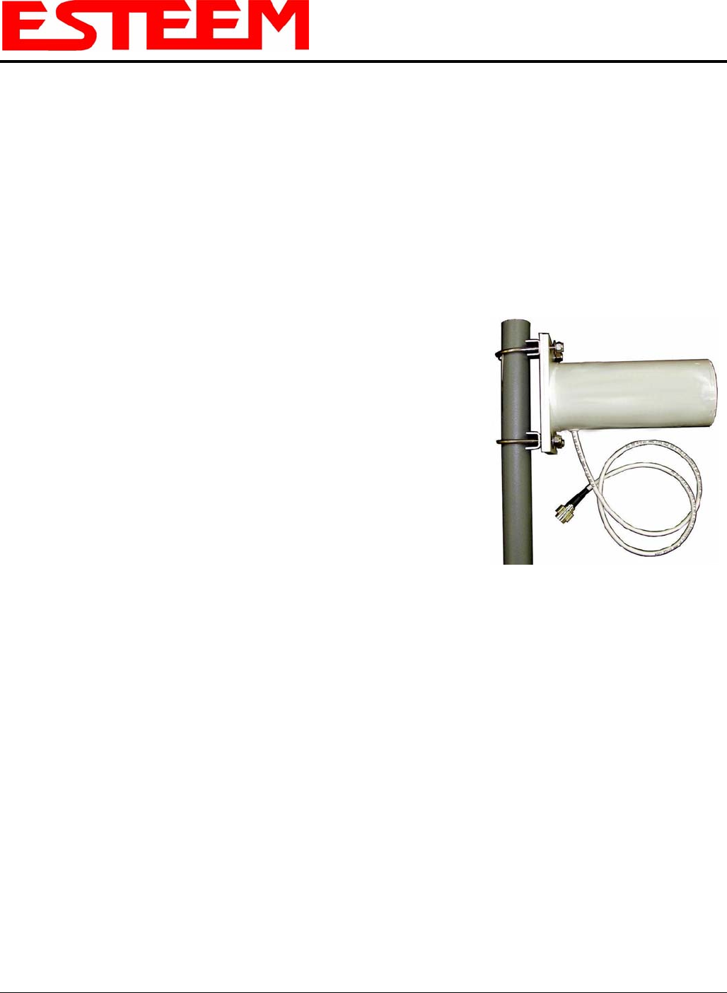
Model No: AA20Ep
Antenna Type: Omni Directional, DC Grounded
Applications: Fixed base
Frequency: 4.9-5.0 GHz
Polarization: Vertical
Impedance: 50 ohms
Gain: 9 dBi (7dBd)
VSWR: 1.2:1 Typical
Front to Back Ratio: n/a
Horizontal Beamwidth: n/a
Vertical Beamwidth: 40 degrees @ ½ power
Antenna Material: Brass radiator, UV inhibited
fiberglass enclosed
Mounting Hardware: Base to Mast, Supplied.
Antenna Connector: TNC-R Male with 36in. pig-tail.
Antenna Envelope: 12 in. length by 1 in. diameter
Weight: 1.5 lbs.
APPENDIX B
SPECIFICATIONS
Antenna Specifications
Revised: 16 Jun 06 APX B-5 EST P/N AA107P
Model No: AA203Ep Caution
To comply with the FCC
exposure compliance
requirements, a separation
distance of at least 20 cm
must be maintained between
the antenna and all persons.
Antenna Type: Directional, DC grounded
Applications: Fixed base.
Frequency: 4.9-5.0 GHz
Polarization: Vertical or Horizontal
Impedance: 50 ohms
Gain: 9 dBi (7 dBd)
VSWR: < 1.5
Model AA203Ep
Front to Back Ratio: 23 dB
Horizontal Beamwidth: 55 degrees @ ½ power
Vertical Beamwidth: 55 degrees @ ½ power
Antenna Material: Sealed in UV stable fiberglass enclosed radome
Mounting Hardware: Stainless steel U bolts (included) for mounting up
to 1 5/8 in. diameter pipe.
Antenna Connector: TNC-R Male with 36in. pig tail
Maximum Power Input: 5 Watts
Antenna Envelope: 4.5 in. length by 3 in. diameter
Windload (RWV): 125 mph
Lateral Thrust at
Rated Wind: 5.8 lbs.
Wind Surface Area: 0.060 ft2
Weight: 1 lbs.
APPENDIX B
SPECIFICATIONS
Antenna Specifications
Revised: 16 Jun 06 APX B-6 EST P/N AA107P
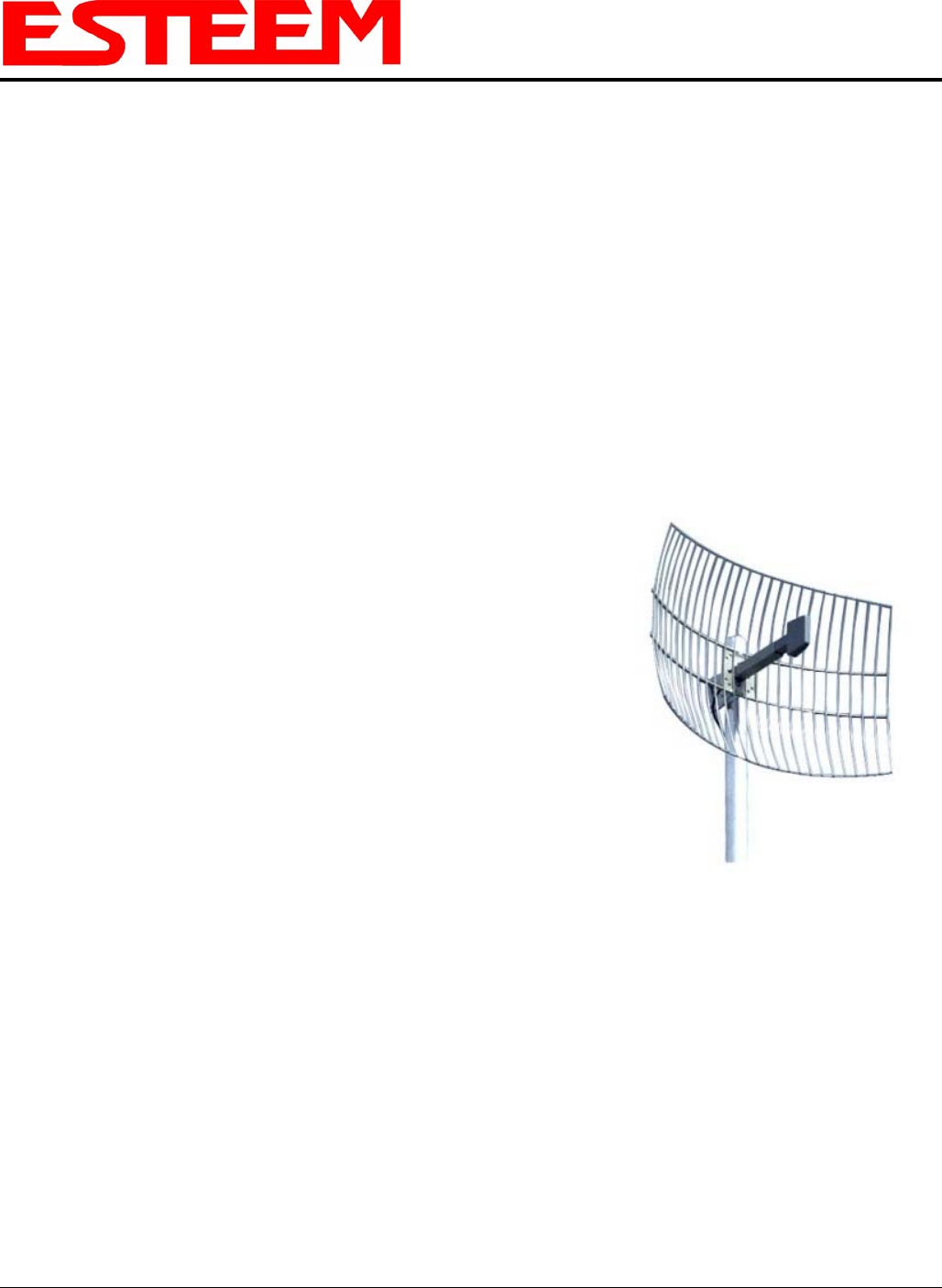
Model No: AA204Ep
Applications: Fixed base mounting
Antenna Type: 2.4 GHz ISM, Directional, DC Grounded, Parabolic Grid
Frequency: 4.9-5.0 GHz
Polarization: Vertical or Horizontal Caution
To comply with the FCC exposure
compliance requirements, a
separation distance of at least 50 cm
must be maintained between the
antenna and all persons.
Impedance: 50 ohms
Gain: 26 dBi (24 dBd) nominal
VSWR: < 1.5:1 nominal
Front to Back Ratio: >24 dB
Horizontal Beamwidth: 16 degrees @ ½ power
Vertical Beamwidth: 11 degrees @ ½ power
Antenna Material: Zinc plated cold rolled steel with polyester power
coat finish
Model AA204Eg
Recommended Mounting
Hardware: Standard U-bolt steel mast clamp complete with
mounting hardware. Designed for masts of up to
2.5 in. O.D.
Antenna Connector: TNC-R Male with 36 in. pig-tail
Maximum Power Input: 10 Watts
Wind Survival: 100 mph
Wind Load: 16 mph
Antenna Envelope: 34 in. length by 17 in. width by 11 in. height
Weight: 3 lbs.