Electronic Systems Technology ESTEEM195EP BASE STATION TRANSMITTER User Manual CHAPTER 2
Electronic Systems Technology BASE STATION TRANSMITTER CHAPTER 2
Contents
- 1. FCC INFORMATION
- 2. SPECIFICATIONS
- 3. INTERFACE PORTS
- 4. RADIO CONFIGURATION
- 5. SECURITY
- 6. TROUBLESHOOTING
- 7. QUICK START GUIDE 1
- 8. FRONT COVER
- 9. TABLE OF CONTENTS
- 10. INTRODUCTION
- 11. CONFIGURATION DIAGRAMS
- 12. STARTING OUT
- 13. WEB CONFIGURATION MANAGER
- 14. EXAMPLE CONFIGURATIONS 1
- 15. EXAMPLE CONFIGURATIONS 2
- 16. REPEATING FIGURES
- 17. ANTENNA SETUP
- 18. QUICK START GUIDE 2
- 19. QUICK START GUIDE 3
REPEATING FIGURES
CHAPTER 6
REPEATING FEATURES
Revised: 16 Jun 06 6-1 EST P/N AA107P
To increase the wireless network’s area of coverage for
both indoor and outdoor applications, the ESTeem 195Ep
utilizes a custom repeating feature that allows increased
coverage areas without the added expense of hard cabling
or adding an additional point to point radio link.
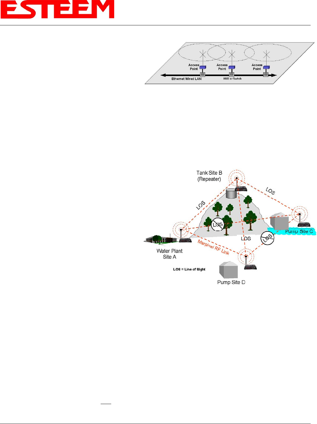
With a conventional IEEE 802.11g or 802.11b Access
Point (AP) network, all of the APs have to be interfaced
to a common network either by hardwire, see Figure 1, or
a separate, dedicated RF backbone. The Model 195Ep
can create this RF backbone, bridge Ethernet networks connected to the wired Ethernet port and provide the wireless canopy for
802.11 clients simultaneously.
Figure 1: Conventional Access Point Diagram
When programmed in any of the three Access Point (AP) Repeater Modes, the Model 195Ep will create a wireless network with
other Model 195Ep units in radio range that are programmed in the AP Repeater Peer table during setup. This feature adds the
increased functionality of repeaters to the typical Ethernet Bridge configuration.
ESTEEM MESH NETWORK
One of the most powerful features of the AP Repeater
Mode is the ability to input multiple communication
routes and designate the priority for each of these routes
to create a wireless Mesh network. The ESTeem Model
195Ep will automatically change communication routes
in the network if a route has failed. The new route will be
based upon the priority level set during configuration.
This wireless Meshing technology allows the RF network
to “self-heal” if any of the communication paths fail.
Figure 2: Small Mesh Network Diagram
The routing priority is manually set during the
configuration of the 195Ep. A manual path configuration
is far superior to standard “self-discovery” networks,
because you have direct control over the best RF paths
and can easily identify any failed routes for easy
troubleshooting. For example, Figure 2 shows a typical
wireless Ethernet system used in the Water/Waste Water
Industry. The problem with a standard “self-discovery”
Mesh network is the selection of routes. Notice that the
communication between the Water Plant (Site A) and
Pump Site D has a marginal link, but it is the most direct
route between the Ethernet devices.
This scenario poses the question, which path will the network select? The ESTeem Mesh Network takes out the guessing games
by allowing the user to select and prioritize all communication routes in the system. In our example we would want the primary
link to go through Tank B (Repeater) and use the direct link only if this primary link fails. The following sections will show how
this completed.
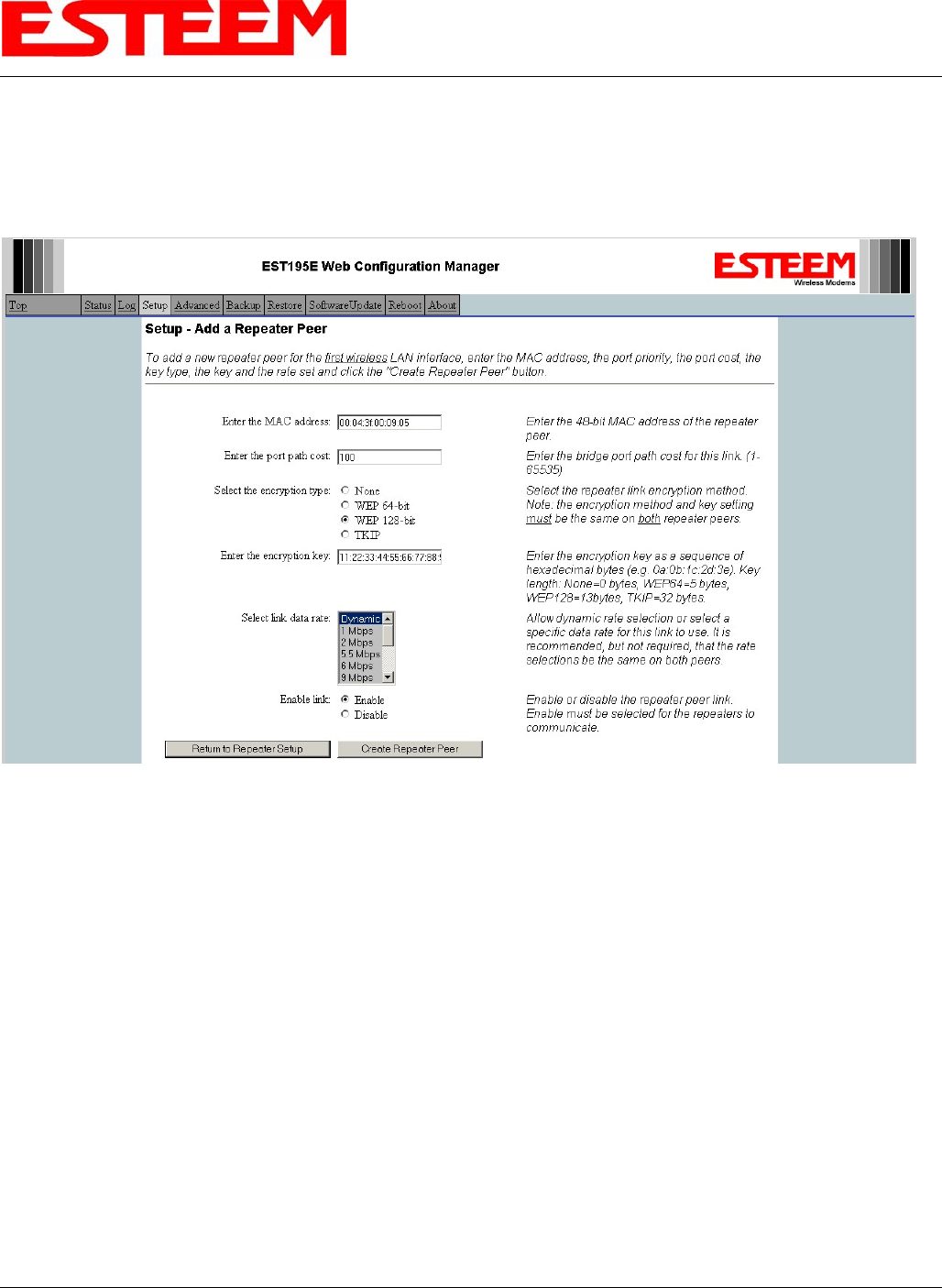
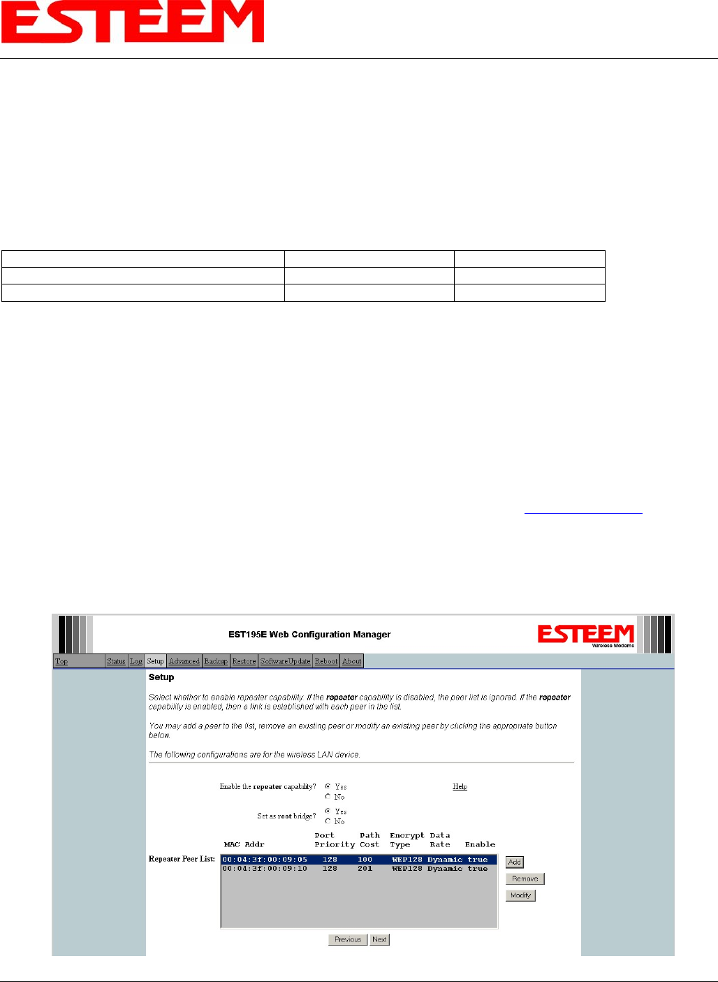
Configuration
The configuration of the repeater paths is completed during setup of the Access Point modes. All three Access Point modes
support repeating and Meshing features. Figure 3 shows an example repeater peer table from the setup menus. For an ESTeem
195Ep to communicate with another ESTeem 195Ep, Yes must be selected at the “Enable Repeater Capability.” Next, the
Wireless LAN (WLAN) MAC address of each Model 195Ep that will have direct communications must be added to the Repeater
Peer List. Finally, enabling the link allows the corresponding 195Ep to be included in the communication routing. Mobile clients
CHAPTER 6
REPEATING FEATURES
Revised: 16 Jun 06 6-2 EST P/N AA107P
do not require input in the repeater peer table. If multiple Mesh routes are configured, you will also need to set the values for
Priority and Path Costs (explained in Spanning Tree below). For multiple examples of repeater configurations, please refer to
Chapter 5 of this user’s manual.
Figure 3: Repeater Configuration Example
SPANNING TREE PROTOCOL (STP)
The ESTeem Model 195Ep uses standard Ethernet Spanning Tree Protocol (STP) to determine the radio routing structure of the
wireless network. The primary purpose of STP is to make sure that “network loops” are not created. A network loop is having
two communication paths to the same destination where the remote device would receive the same data multiple times. If there
were no way to control the data flow, this data would be constantly passed around this loop causing a “packet storm” that would
shut down the entire network. The Spanning Tree Protocol will block all these redundant links.
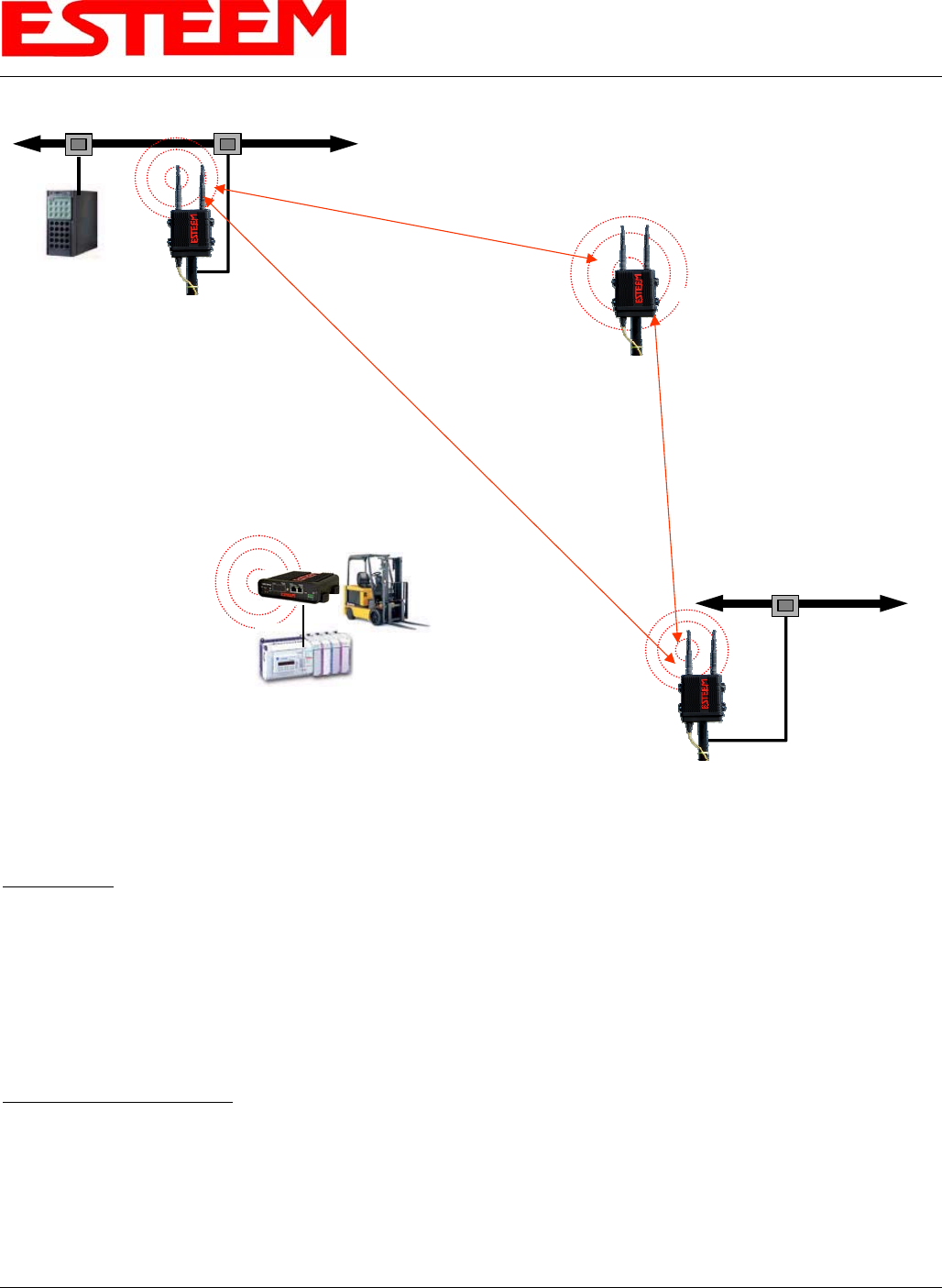
The STP operation begins by determining which Ethernet device on the network will be the Root Bridge. All Ethernet networks
have a Root Bridge that is selected by the lowest MAC address. All path costs are evaluated against this Root Bridge device to
determine routing and which paths will be blocked. On a wired Ethernet network, the location of the Root Bridge is not really
important, but in a wireless network selection of the Root Bridge is critical to the wireless network routing. Let’s use one of the
Example network diagrams from Chapter 5 to continue the discussion (Figure 4).
CHAPTER 6
REPEATING FEATURES
HUB or Switch
Revised: 16 Jun 06 6-3 EST P/N AA107P
The following sections describe the process of the STP in the ESTeem Model 195Ep as how it would happen in the above
example.
Learning Phase - Once properly configured, each Model 195Ep will begin to search out the other Model 195Ep units in radio
range that are programmed in the AP Repeater Peer table. All Model 195Ep’s will calculate their routes to every Model 195Ep in
the network based upon the lowest “path cost” to the Root Bridge. Path cost is the total cost of transmitting a packet through the
wireless network to the Root Bridge. Note: The Root Bridge in a network should be the Model 195Ep where the majority of the
data flow is processed. In every wireless network of two or more radios, the Root Bridge should be user defined. If not defined,
the ESTeem 195Ep with the lowest MAC address will be designated as the Root Bridge.
In Figure 4, the Plant network (Example 1) is the most logical location for the Root Bridge based upon the amount of data flow.
Setting this site as the root bridge is discussed below in Root Bridge.
Blocking and Forwarding Phase – To ensure you do not have a network loop situation due to redundant paths in your wireless
network, the Model 195Ep will recognize and disable (block) one or more redundant links and provide back up links should the
primary link fail. This establishes a wireless mesh network with a series of forwarding links, based upon the shortest path cost to
the Root Bridge.
For example, looking at Figure 4, the Remote Building has two routes to the Root Bridge (Plant Network – Example #1); directly
to the site and through the repeater. The direct link between the two sites is the shortest route (lowest Path Cost) and will be
selected as the primary route unless overridden by manually changing the Path Cost in the configuration.
Access Point Router
with Repeater
Feature Enabled
10/100BaseT
Mobile
PLC
EtherStation
Mode
10/100BaseT
Access Point Bridge
with Repeater
Feature Enabled
Primary Repeater Path
Backup Repeater Path
Access Point Bridge
with Repeater
Feature Enabled
Mobile Vehicle
Single Ethernet Device
Example #4
S/N: 14004
Primary Repeater Path
Plant Network
Large Wired LAN
Example #1
S/N: E-14001
WLAN MAC=00:04:3F:00:09:01
Remote Building
Small Ethernet Wired LAN
Example #3
S/N: E-14003
WLAN MAC=00:04:3F:00:09:10
Stand-Alone Repeater Site
Example #2
S/N: E-14002
WLAN MAC= 00:04:3F:00:09:05
Network
Router
(Required)
Figure 4: Programming Example #1 Diagram
CHAPTER 6
REPEATING FEATURES
Revised: 16 Jun 06 6-4 EST P/N AA107P
Path Cost
If more than one communication path to the Root Bridge is found, the 195Ep must determine which route to take based upon the
lowest Path Cost. The default path cost to all links in the 195Ep network is 100. If the Path Costs are equal then the lowest MAC
address will determine the priority route. In the ESTeem Mesh Network we want to directly control all data flow so do not want
the routes to be automatically determined.
Looking again at our Example in Figure 4, if we made no changes to the default path cost of 100 (note values in Figure 3) the
lowest path cost would be direct from the Remote Building to the Root Bridge (Plant Network).
Link Description Number of Routes Total Path Cost
Direct from Remote Building 1 100
Remote Build to Root Bridge Through Repeater 2 200
To configure the 195Ep to select the repeater as the primary radio path, set the path cost value for the direct link greater than 200
to make this the primary radio path. The lowest path cost will identify the highest priority. The Model 195Ep will use this routing,
but also switch to direct communication if the repeater were to disappear.
Root Bridge
In any Access Point Repeater network consisting of more than two sites, one Model 195Ep should be designated as the Root
Bridge. Only one Model 195Ep can be designated as the Root Bridge in a given network and should be located where the majority
of the Ethernet data flow is processed. This site may be the Master location in a SCADA network or could be configured at a
repeater site. Selection is important because all Model 195Ep’s NOT configured as the Root Bridge will choose routing based
upon the Path Cost to the Root Bridge. If you have any question as to which site in your AP Repeater application should be the
Root Bridge, contact ESTeem Customer Support at 509-735-9092 or e-mail your application to support@esteem.com.
The Root Bridge will be selected in one of two ways: the Root Bridge can be manually set (recommended) during the
configuration of the Repeater Peer table (Figure 3) or the Root Bridge designation will default to the lowest MAC address of all
the Model 195Ep’s in the network. The manual Root Bridge configuration is located in the “Advanced Settings” section.
Figure 3: Repeater Configuration Example
CHAPTER 6
REPEATING FEATURES
Revised: 16 Jun 06 6-5 EST P/N AA107P
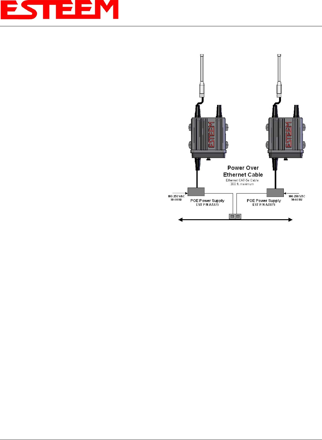
Redundant Backup
The ESTeem Model 195Ep configured in Access Point
Repeater mode will automatically function as a redundant
backup if two Model 195Ep’s are installed at the same location
(Figure 7). If two Model 195Ep’s are connected to the same
HUB or Switch, one of the Model 195Ep’s will be Blocked
when the Spanning Tree Protocol is completed. The network
will continue to use this route until any problem with the
original Model 195Ep is detected and the second Model 195Ep
will begin operation at that site.
Figure 7: Redundant Backup Diagram
Redundant Master Configuration – The configuration in
Figure 7 will also provide a redundant backup for the Master
Site (Root Bridge). Configure both Model 195Ep’s as Root
Bridges (see above) giving the primary Root Bridge a value of 1
and the secondary Root Bridge a value of 2.