Honeywell LXE4830P 802.11g COMPACT FLASH MODULE User Manual VX6 User s Guide
Honeywell International, Inc. 802.11g COMPACT FLASH MODULE VX6 User s Guide
Contents
- 1. Manual HX1 rev3
- 2. Manual MX3X rev3
- 3. Manual MX5X rev3
- 4. Manual MX7 rev3
- 5. User Manual HX2
- 6. User Manual MX7
- 7. users manual
- 8. USERS MANUAL
- 9. User Manual MX3X
- 10. User Manual VX3X
- 11. User Manual VX6 part 1
- 12. User Manual VX6 part 2
- 13. User Manual VX7 part 1
- 14. User Manual VX7 part 2
- 15. Users Manual F300
- 16. Users Manual MX9
User Manual VX6 part 1
VX6 User’s Guide
Copyright © November 2007 by LXE Inc.
All Rights Reserved
E-EQ-VX6OGWW-F
LANGUAGE: ENGLISH
Notices
Notice:
LXE Inc. reserves the right to make improvements or changes in the products described in this manual at any time
without notice. While reasonable efforts have been made in the preparation of this document to assure its
accuracy, LXE assumes no liability resulting from any errors or omissions in this document, or from the use of the
information contained herein. Further, LXE Incorporated, reserves the right to revise this publication and to make
changes to it from time to time without any obligation to notify any person or organization of such revision or
changes.
Copyright Notice:
This manual is copyrighted. All rights are reserved. This document may not, in whole or in part, be copied, photocopied,
reproduced, translated or reduced to any electronic medium or machine-readable form without prior consent, in writing, from
LXE Inc.
Copyright © 2007 by LXE Inc. An EMS Technologies Company.
125 Technology Parkway, Norcross, GA 30092 U.S.A. (770) 447-4224
Trademarks:
LXE® and Spire are registered trademarks of LXE Inc. RFTerm® is a registered trademark of EMS Technologies, Norcross,
GA.
Microsoft, Windows and the Windows logo are registered trademarks of Microsoft Corporation in the United States and/or
other countries.
Java® and Java-based trademarks and logos are trademarks or registered trademarks of Sun Microsystems, Inc. in the U.S. or
other countries, and are used under license.
Intel and Intel XScale are trademarks or registered trademarks of Intel Corporation or its subsidiaries in the United States and
other countries.
RAM® and RAM Mount™ are both trademarks of National Products Inc., 1205 S. Orr Street, Seattle, WA 98108.
The Cisco Square Bridge logo is a trademark of Cisco Systems, Inc.; Aironet, Cisco and Cisco Systems are registered
trademarks of Cisco Systems, Inc. and/or its affiliates in the United States and certain other countries.
Summit Data Communications, Inc. Summit Data Communications, the Summit logo, and “The Pinnacle of Performance” are
trademarks of Summit Data Communications, Inc. All rights reserved.
Symbol, the Symbol logo and Spectrum24 are registered trademarks of Symbol Technologies, Inc.
The Bluetooth® word mark and logos are owned by the Bluetooth SIG, Inc. and any use of such marks by LXE, Inc. is under
license.
Wavelink® and Wavelink Avalanche® are registered trademarks and the Wavelink logo, tagline and Avalanche MC are
trademarks of Wavelink Corporation, Kirkland, WA.
All other brand or product names are trademarks or registered trademarks of their respective companies or organizations.
When this manual is in PDF format: “Acrobat® Reader® Copyright © 2007 Adobe Systems Incorporated. All rights reserved.
Adobe®, the Adobe logo, Acrobat®, and the Acrobat logo are registered trademarks of Adobe Systems Incorporated.” applies.
!
The user is strongly cautioned to read Appendix B, “Regulatory Notices and Safety
Information”. Important safety cautions, warnings and regulatory information is contained in
Appendix B.
Important: This symbol is placed on the product to remind users to dispose of Waste Electrical
and Electronic Equipment (WEEE) appropriately, per Directive 2002-96-EC. In most areas, this
product can be recycled, reclaimed and re-used when properly discarded. Do not discard labeled
units with trash. For information about proper disposal, contact LXE through your local sales
representative, or visit www.lxe.com.

Revision Notice
VX6 User’s Guide
Upgrade From Revision E to Revision F
Section Explanation
Entire Manual Updated specific references to Microsoft Windows CE .NET to
generic references to Microsoft Windows CE to reflect the availability
of either Windows CE .NET or CE 5.0 operating systems on the VX6.
Added Bluetooth information and instruction.
Accessories Revised Accessories listing.
Strain Relief Cable Clamps Added new section.
AppLock and the VX6 Revised section.
Appendix B – Regulatory Notices and
Safety Information
Added translated Chinese Class A statement and Republic of
Singapore IDA Standards text.
Revised “R&TTE Directive Requirements”.
Note: A complete revision history is included in Appendix B, “Regulatory Notices and Safety Information”.


E-EQ-VX6OGWW-F VX6 User’s Guide
Table of Contents
THE VX6 VEHICLE MOUNT COMPUTER 1
Introduction............................................................................................................... 1
Document Conventions ............................................................................................................2
Environmental Specifications...................................................................................................3
Quick Start................................................................................................................. 4
Troubleshooting........................................................................................................................5
Components.............................................................................................................. 6
The Half-Screen Display........................................................................................... 9
VX6 Control Panel..................................................................................................... 9
Microsoft Windows CE Control Panel..................................................................... 9
PCMCIA, ATA and SD Slots ..................................................................................... 9
AppLock and the VX6............................................................................................. 10
Single Application AppLock ..................................................................................................10
Multi Application AppLock ...................................................................................................10
Using the Touchscreen .........................................................................................................10
Using the Keypad .................................................................................................................11
The QWERTY Keyboard ......................................................................................... 12
IBM 3270 Overlay..................................................................................................................12
IBM 5250 Overlay..................................................................................................................12
Key Maps................................................................................................................................13
Unused Key Functions .........................................................................................................13
Custom Key Maps ..................................................................................................................13
NumLock and the VX6...........................................................................................................13
Keyboard Backlight................................................................................................................13
Keyboard LEDs ......................................................................................................................14
CAPS LED ...........................................................................................................................14
Secondary Keys LED ...........................................................................................................15
Control Keys ........................................................................................................................16
General Windows CE Keyboard Shortcuts ............................................................................17
Input Panel (Virtual Keyboard) ..............................................................................................18
Enabling the Input Panel ......................................................................................................19
Power Supply .......................................................................................................... 20
Uninterruptible Power Supply Battery Pack ..........................................................................20
Backup Battery .......................................................................................................................20
Getting Help............................................................................................................. 21
Manuals and Accessories ...................................................................................... 21

ii Table of Contents
VX6 User’s Guide E-EQ-VX6OGWW-F
Manuals...................................................................................................................................21
Accessories .............................................................................................................................21
INSTALLATION 25
Install Mounting Brackets ...................................................................................... 25
RAM Mount System...............................................................................................................26
Components..........................................................................................................................26
Torque Measurements ..........................................................................................................26
Procedure..............................................................................................................................27
Step 1a – Mount Vehicle RAM Ball Base ..................................................................................... 27
Mounting Dimensions .....................................................................................................27
Step 1b – Mount Vehicle RAM Clamp Mount.............................................................................. 28
Mounting Dimensions .....................................................................................................29
Step 2 – Attach RAM Mount Ball to the VX6............................................................................... 30
Step 2 – Attach VX6 Assembly to RAM Mount ........................................................................... 31
Completed Assembly..............................................................................................................32
U-Bracket Mount System .......................................................................................................33
Components..........................................................................................................................33
Mounting Positions ..............................................................................................................33
Torque Measurements ..........................................................................................................34
Procedure..............................................................................................................................35
Step 1 - Mount Bottom Mounting Bracket To Vehicle. ................................................................ 35
Mounting Dimensions .....................................................................................................35
Step 2 - Connect Rear Bracket to VX6 .......................................................................................... 36
Step 3 - Attach VX6 Assembly To Bottom Mounting Bracket. .................................................... 37
Completed Assembly..............................................................................................................39
Install Stylus Tether and Sleeve .............................................................................................40
Install/Remove Touchscreen Protective Film.........................................................................41
UPS Battery Pack Remote Mount ..........................................................................................42
UPS Battery Pack Remote Mounting Dimensions...............................................................42
Connect Antenna .................................................................................................... 43
External Antenna ....................................................................................................................43
Remote Vehicle Mount Antenna ............................................................................................43
Internal Antenna .....................................................................................................................44
Connect Serial Barcode Scanner .......................................................................... 45
Connect Serial Printer or PC.................................................................................. 47
Ethernet and USB Ports ......................................................................................... 48
USB Mouse.............................................................................................................................49
Connect External Headset...................................................................................... 50
Connect Power Cable and Optional UPS Battery Pack ....................................... 51
External Power Supply, Optional........................................................................... 52
Vehicle 12-80VDC Power Connection ................................................................... 53

Table of Contents iii
E-EQ-VX6OGWW-F VX6 User’s Guide
Power Adapter Cable.............................................................................................. 59
Fuse Replacement for the VX6 .............................................................................. 60
Strain Relief Cable Clamps .................................................................................... 61
OPERATION 63
Powering On/Off...................................................................................................... 63
Display and Touchscreen....................................................................................... 64
Adjusting Screen Display .......................................................................................................64
Cleaning the Display ..............................................................................................................64
Disabling the Touchscreen .....................................................................................................64
Disabling the Touchscreen Heater..........................................................................................64
Calibrating the Touchscreen...................................................................................................65
Touchscreen Protective Film ..................................................................................................65
Touchscreen and USB Mouse ................................................................................................65
Adjust Speaker Volume.......................................................................................... 66
Microsoft Windows CE Event Sounds...................................................................................66
Power Management ................................................................................................ 66
Laser Barcode Scanner Warnings......................................................................... 67
Enter Data................................................................................................................ 67
Keyboard Entry.......................................................................................................................68
Touchscreen Entry..................................................................................................................68
Right Click ...........................................................................................................................68
Tethered Scanners...................................................................................................................69
Aiming the Barcode Scanner................................................................................................69
Distance from Label .............................................................................................................69
Successful Scan ....................................................................................................................69
Unsuccessful Scan................................................................................................................69
Bluetooth Scanners .................................................................................................................70
Voice Data ..............................................................................................................................70
Bluetooth Devices................................................................................................... 71
APPENDIX A KEY MAPS 73
The VX6 Keypad...................................................................................................... 73
Key Map 101-Key Equivalencies...........................................................................................73
IBM 3270 Keypad Overlay ....................................................................................................78
IBM 5250 Keypad Overlay ....................................................................................................78

iv Table of Contents
VX6 User’s Guide E-EQ-VX6OGWW-F
APPENDIX B REGULATORY NOTICES AND SAFETY INFORMATION 79
Approvals ................................................................................................................ 80
Revision History...................................................................................................... 91
INDEX 93
Illustrations
Figure 1 VX6 Components, Top View ................................................................................................................6
Figure 2 VX6 Components, Front View..............................................................................................................6
Figure 3 VX6 Components, Bottom View...........................................................................................................7
Figure 4 VX6 Components, Back View ..............................................................................................................7
Figure 5 VX6 Control Panel ................................................................................................................................7
Figure 6 VX6 Access Panel .................................................................................................................................8
Figure 7 The VX6 PCMCIA, CF and SD Slots ...................................................................................................9
Figure 8 Switchpad Menu..................................................................................................................................10
Figure 9 QWERTY Keyboard Standard ............................................................................................................12
Figure 10 QWERTY Keyboard with IBM 3270 Overlay..................................................................................12
Figure 11 QWERTY Keyboard with IBM 5250 Overlay..................................................................................12
Figure 12 Keyboard LEDs.................................................................................................................................14
Figure 13 The CapsLock Key ............................................................................................................................14
Figure 14 The Secondary Key ...........................................................................................................................15
Figure 15 Keyboard Display Controls ...............................................................................................................16
Figure 16 Small and Large Virtual Keyboards ..................................................................................................18
Figure 17 Input Panel Properties........................................................................................................................19
Figure 18 Connect Vehicle RAM Mount Bracket to Vehicle............................................................................27
Figure 19 VX6 RAM Bracket - Mounting Dimensions (Not To Scale) ............................................................27
Figure 20 RAM Clamp Mount Components......................................................................................................28
Figure 21 Assembled RAM Clamp Mount ........................................................................................................28
Figure 22 RAM Clamp Mount - Mounting Dimensions (Not To Scale) ...........................................................29
Figure 23 Attach RAM Mount to VX6..............................................................................................................30
Figure 24 RAM Assembly .................................................................................................................................31
Figure 25 Completed RAM Mount Assembly ...................................................................................................32
Figure 26 Suggested Mounting Positions ..........................................................................................................33
Figure 27 Connect Bottom Bracket to Vehicle..................................................................................................35
Figure 28 VX6 Bracket - Mounting Dimensions (Not To Scale) ......................................................................35
Figure 29 Attach Rear Bracket to VX6..............................................................................................................36
Figure 30 Attach VX6 Assembly to Bottom Bracket ........................................................................................37
Figure 31 Integrated UPS Battery Pack Mount .................................................................................................38
Figure 32 VX6 in Vehicle Bracket ....................................................................................................................39
Figure 33 Stylus Tether Mounting Holes...........................................................................................................40
Figure 34 Tethered Stylus, Typical Installation.................................................................................................40
Figure 35 VX6 Touchscreen Protective Film ....................................................................................................41
Figure 36 Remote UPS Battery Pack Mount .....................................................................................................42
Figure 37 UPS Battery Pack Remote Mounting Dimensions ............................................................................42
Figure 38 Connect External 2.4GHz Antenna ...................................................................................................43
Figure 39 Internal Antenna Cables ....................................................................................................................44
Figure 40 Connect Serial Scanner Cable ...........................................................................................................45
Figure 41 VX6 with Generic Barcode Scanner Attached ..................................................................................46

Table of Contents v
E-EQ-VX6OGWW-F VX6 User’s Guide
Figure 42 Generic Barcode Scanner ..................................................................................................................46
Figure 43 Connect Serial Cable to COM3 .........................................................................................................47
Figure 44 VX6 Ethernet/USB-H/USB-C Dongle Cables ..................................................................................48
Figure 45 Connect Ethernet/USB Dongle Cable ...............................................................................................48
Figure 46 Connect USB Device to Dongle Cable..............................................................................................49
Figure 47 Connect Ethernet Cable to Adapter Cable.........................................................................................49
Figure 48 Connect External Headset .................................................................................................................50
Figure 49 Connect Power Cable to VX6 ...........................................................................................................51
Figure 50 Optional Power Configuration ..........................................................................................................52
Figure 51 Vehicle Power Connection Cable (Fuse Not Shown)........................................................................53
Figure 52 Connecting the Power Cable to the Vehicle......................................................................................53
Figure 53 Vehicle Connection Wiring Color Codes..........................................................................................54
Figure 54 Direct Connection (No UPS Battery Pack) .......................................................................................55
Figure 55 Integrated Mount UPS Battery Pack Connection ..............................................................................56
Figure 56 Remote Mount UPS Battery Pack Connection ..................................................................................57
Figure 57 Power Adapter Cable, VX1/2/4 to VX6............................................................................................59
Figure 58 Fuse Replacement..............................................................................................................................60
Figure 59 Strain Relief Cable Clamps ...............................................................................................................61
Figure 60 Slide Clamp Over Cable....................................................................................................................61
Figure 61 The VX6 Power Switch.....................................................................................................................63
Figure 62 Touchscreen Calibration, Calibration Targets...................................................................................65
Figure 63 Caution Labels Class II Scanner........................................................................................................67
Figure 64 Caution Labels Class IIIA Scanner ...................................................................................................67
Figure 65 Scan Beam.........................................................................................................................................69
Figure 66 VX6 QWERTY Keyboard ................................................................................................................73
Figure 67 IBM 3270 Specific Keypad ...............................................................................................................78
Figure 68 IBM 5250 Specific Keypad ...............................................................................................................78

vi Table of Contents
VX6 User’s Guide E-EQ-VX6OGWW-F
E-EQ-VX6OGWW-F VX6 User’s Guide
The VX6 Vehicle Mount Computer
Introduction
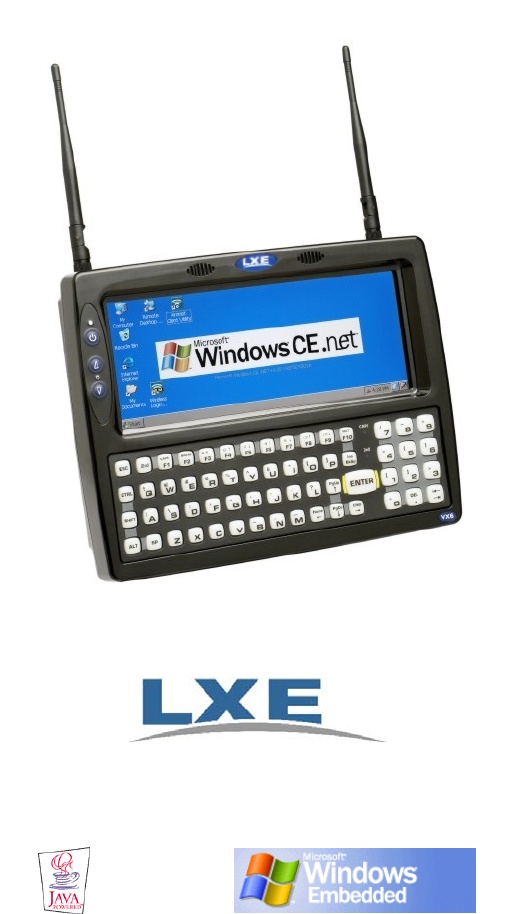
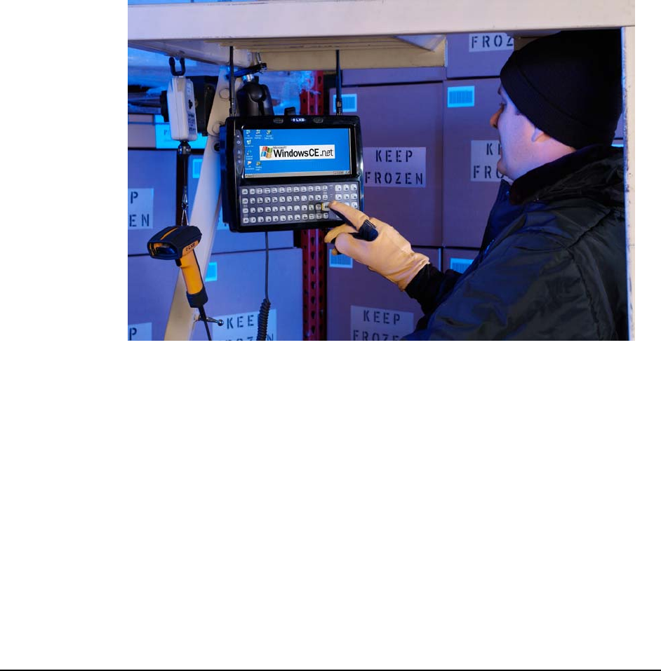
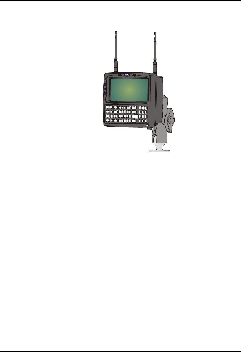
The VX6 Vehicle Mount Computer (VMC) is a rugged, vehicle-mounted, Microsoft® Windows®
CE equipped computer. The VX6 is capable of wireless data communications from a fork-lift
truck or any properly configured vehicle using a 2.4 GHz radio.
The VX6 features a half screen SVGA color TFT display. The touch-screen display supports
graphic features and Microsoft Windows CE icons that the Windows CE operating system
supports. The keyboard is illuminated to facilitate use in dimly lit areas.
The VX6 provides the power and functionality of a desktop computer in a vehicle mounted unit,
with a wide range of options:
• 400MHz Intel® PXA255 CPU
• Windows CE .NET or CE 5.0 Operating System
• Wireless LAN radios with internal, single external or dual external antenna options
• Optional Bluetooth module
• Ethernet port
• USB Host and Client ports
• Choice of indoor or outdoor half screen display
• Available touch screen protective film
• Available Uninterruptible Power Supply (UPS) Battery Pack
2 Introduction
VX6 User’s Guide E-EQ-VX6OGWW-F
• Available RAM MountTM options
• Extended temperature version includes touchscreen heater
Note: The “VX6 Reference Guide” contains VX6 technical information and advanced
functions.
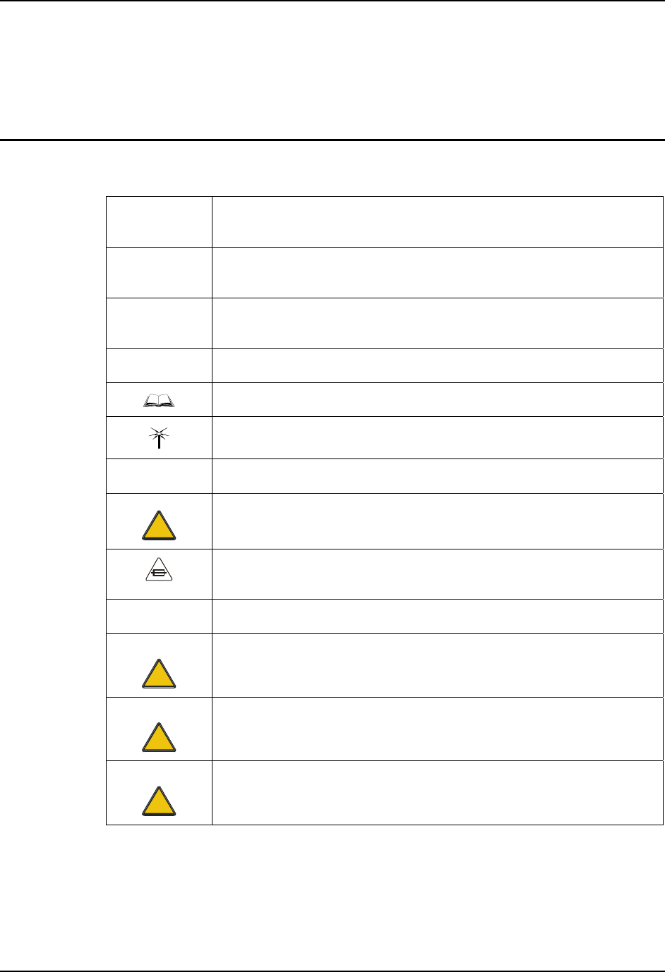
Document Conventions
This reference guide uses the following document conventions:
ALL CAPS All caps are used to represent disk directories, file names, and application
names.
Menu|Choice Rather than use the phrase “choose the Save command from the File menu”,
this manual uses the convention “choose File|Save”.
“Quotes” Indicates the title of a book, chapter or a section within a chapter (for
example, “Document Conventions”).
< > Indicates a key on the keyboard (for example, <Enter> ).
Indicates a reference to other documentation.
Differences in operation or commands due to radio type.
ATTENTION Keyword that indicates vital or pivotal information to follow.
!
Attention symbol that indicates vital or pivotal information to follow. Also,
when marked on product, means to refer to the manual or operator’s guide.
International fuse replacement symbol. When marked on the product, the
label includes fuse ratings in volts (v) and amperes (a) for the product.
Note: Keyword that indicates immediately relevant information.
Caution
!
Keyword that indicates a potentially hazardous situation, which, if not
avoided, may result in minor or moderate injury.
WARNING
!
Keyword that indicates a potentially hazardous situation, which, if not
avoided, could result in death or serious injury.
DANGER
!
Keyword that indicates an imminent hazardous situation, which, if not
avoided, will result in death or serious injury.
Introduction 3
E-EQ-VX6OGWW-F VX6 User’s Guide
Environmental Specifications
Feature Specification
Operating Temperature
Standard version -4°F to 122°F (-20°C to 50°C) [non-condensing]
Extended Temperature version -22º to 122º F (-30ºC to 50ºC [condensing]
Storage Temperature
Standard version -22°F to 140°F (-30°C to 60°C) [non-condensing]
Extended Temperature version -22°F to 140°F (-30°C to 60°C) [condensing]
Water, Sand Dust IP66 per IEC60529
Operating Humidity
Standard version Up to 90% non-condensing at 104°F (40°C)
Extended Temperature version 100%
Vibration Based on MIL Std 810F
ESD 15 kV
Bluetooth Range 32.8 feet (10 meters) Direct line of sight only

4 Quick Start
VX6 User’s Guide E-EQ-VX6OGWW-F
Quick Start
This section’s instructions are based on the assumption that your new system is pre-configured
and requires only accessory installation (e.g. antenna and/or barcode scanner) and a power source.
Use this guide as you would any other source book -- reading portions to learn about the VX6,
and then referring to it when you need more information about a particular subject. This guide
takes you through installation and operation of the LXE VX6.
In general, the sequence of events is:
1. Install Vehicle Mounting Bracket on vehicle and secure VX6 in Mounting Bracket
Assembly (see “Installation”, later in this manual).
2. Connect power cable to the VX6. The power cable can also be connected to a UPS
battery pack, which is then connected to the VX6.
3. Connect accessories to VX6, e.g. scanner, antenna, etc.
4. Secure all cables to the VX6 with the Strain Relief Cable Clamps.
5. Turn the VX6 on.
6. When instructed, calibrate the touchscreen.
7. The screen may appear white while applications and drivers are loading. When
complete, set Date and Time (see the “VX6 Reference Guide”).
8. Configure radio (see the VX6 Reference Guide”).
9. Warmboot to ensure all registry settings are saved.
10. Device is ready for use.
The VX6 should be mounted in an area in the vehicle where it:
• Does not obstruct the vehicle driver’s vision or safe vehicle operation.
• Can be easily accessed by anyone seated in the driver’s seat.
!
If your VX6 has AppLock installed, please contact your system administrator
for setup and processing information.
AppLock is configured by an administrator to limit general users to only certain
programs.

Quick Start 5
E-EQ-VX6OGWW-F VX6 User’s Guide
Troubleshooting
Can’t calibrate the touch
screen, change the date/time
or adjust the volume.
AppLock is installed and running on the mobile device. AppLock
restricts User access to running programs. Changes or
modifications require Administrator access.
Refer to AppLock in the VX6 Reference Guide for setup and
processing information.
RFterm opens and runs upon
each cold reset and warm
reset.
Tap File | Exit to close the RFTerm application.
The VX6 seems to lockup as
soon as it is warm booted. There may be small delays while the wireless client connects to
the network, authorization for Voxware-enabled applications
complete, Wavelink Avalanche management of the VX6 startup
completes, and Bluetooth relationships establish or re-establish.
6 Components
VX6 User’s Guide E-EQ-VX6OGWW-F
Components
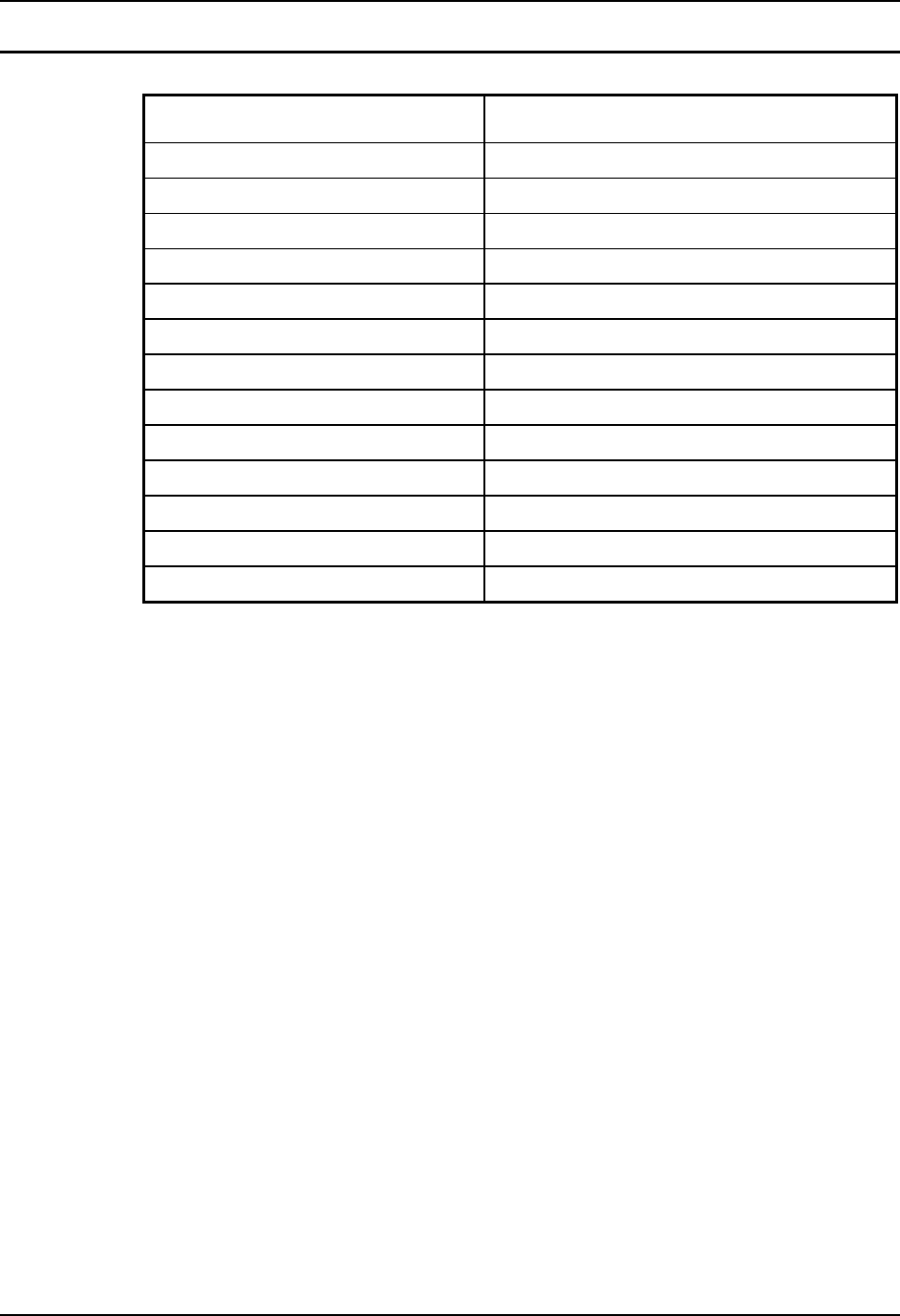
2
1
1. Access Panel Cover (See
Following Illustrations for
Detail)
2. Antenna Connectors or
Hole Plugs
Figure 1 VX6 Components, Top View
Note: When the internal antenna option is ordered, the internal antenna is mounted on the
inside of the Access Panel Cover.
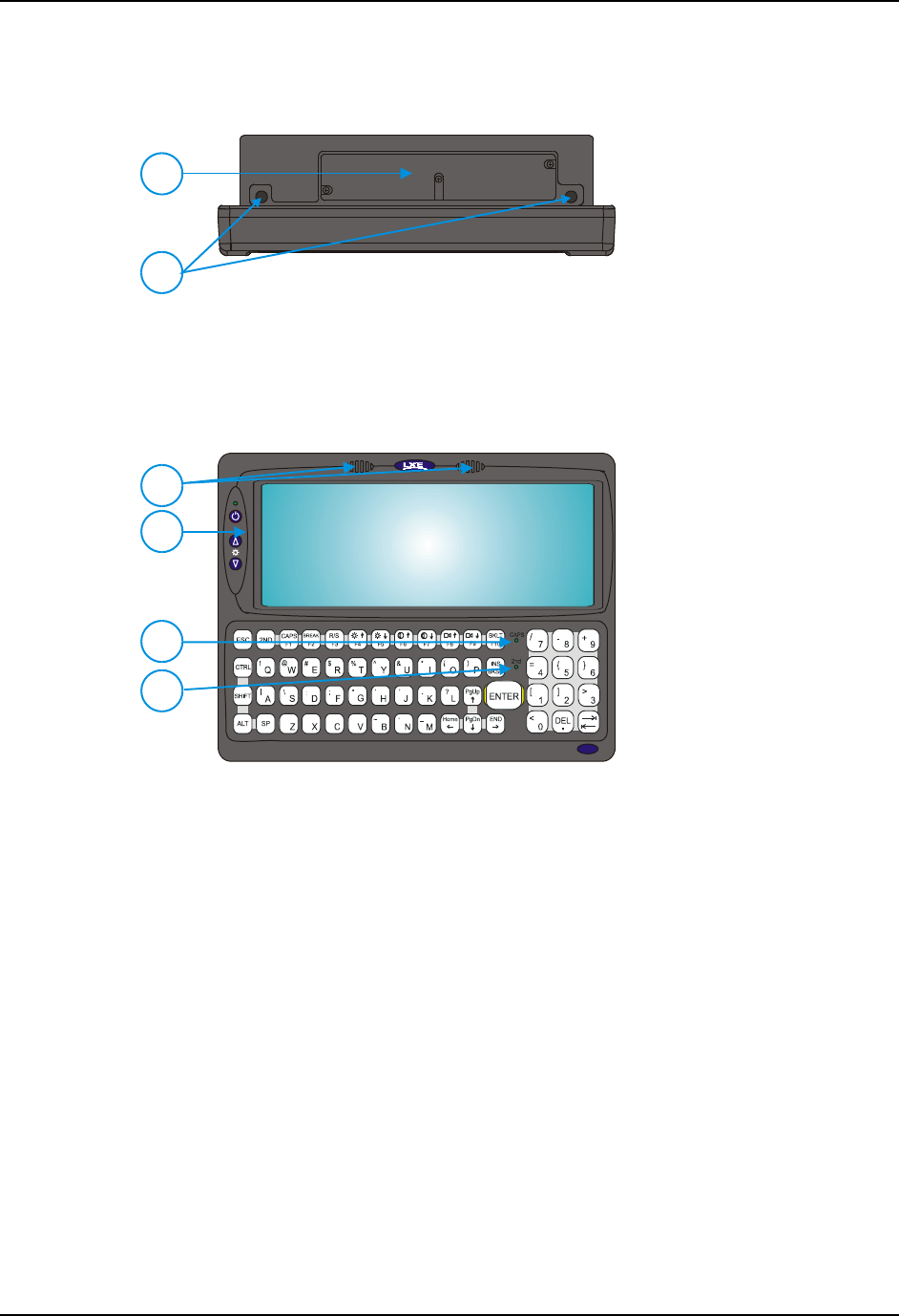
1
2
V
X6
4
3
1. Speakers
2. Control Panel
(See Following
Illustrations for Detail)
3. 2nd Indicator
4. Caps Lock Indicator
Figure 2 VX6 Components, Front View
Components 7
E-EQ-VX6OGWW-F VX6 User’s Guide
T10A, 125V
INPUT:
12-80VDC
6A 72W
AUDIO
ETHERNET /
USB
KEYBOARD /
MOUSE
COM2/3COM1 / SCANNER
N107
REFER TO
MANUAL
IP66
LISTED
I.T.E.
E-130794
C
PRODUCT OF U.S.A. U.S. PATENT 5862393
US
UL
®
THIS DEVICE COMPLIES WITH PART 15 OF THE FCC RULES.
OPERATION IS SUBJECT TO THE FOLLOWING TWO
CONDITIONS: (1) THIS DEVICE MAY NOT CAUSE HARMFUL
INTERFERENCE, AND (2) THIS DEVICE MUST ACCEPT ANY
INTERFERENC E RECEIVED, INCLUD ING INTERFERENCE
THAT MAY CAUSE UNDESIRED OPERATION.
This Class A digital apparatus complies with
Canadian ICE-003.
Cet appareil num de la Classe Aest
confirme l érique
orme NMB-003 du Canadaà n
CAUTION: For continues protection against risk of fire,
replace only with same type and rating of fuse.
ATTENTION: Pour ne pas compromette la preotection
contre les risques d'incendie, remplacer par un fusible
de mmes types de mmes caractristques nominales.êêé
67
54
3
2
1
1. COM1/Scanner
Connector
2. COM3 Connector
3. Keyboard/Mouse
Connector (Not Used)
4. Ethernet/USB Cable
Connector (USB-Host and
USB-Client)
5. Fuse
6. Audio Connector
7. Power Cable Connector
Figure 3 VX6 Components, Bottom View
Note: COM1 is configured with Pin 9 +5V. COM3 is labeled “COM2/3” and is configured
with Pin 9 RI. Please see the VX6 Reference Guide for details.
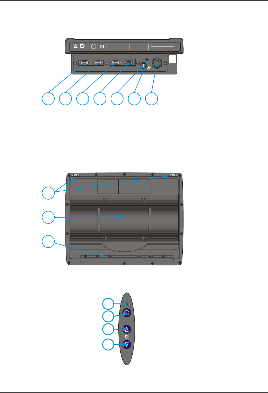
3
2
1
1. Antenna Connectors or
Plugs
2. Bracket Mounting Area
3. Strain Relief Bracket and
Screws
Figure 4 VX6 Components, Back View
1
2
4
3
1. Power LED
2. Power Switch
3. Brightness Increase
4. Brightness
Decrease
Figure 5 VX6 Control Panel

8 Components
VX6 User’s Guide E-EQ-VX6OGWW-F
SD CF ATA
PCMCIA A
PCMCIA B
21 3
1. SD Memory Card
Slot
2. Compact Flash ATA
Hard Drive
3. PCMCIA Slots
Figure 6 VX6 Access Panel
Note: The tethered access panel cover is not shown in the illustration above.
The Half-Screen Display 9
E-EQ-VX6OGWW-F VX6 User’s Guide
The Half-Screen Display
The VX6 has a half screen TFT color display capable of supporting SVGA graphics mode. The
resolution is 800 x 320 pixels.
VX6 Control Panel
The VX6 control panel contains the status LED, power button and display brightness adjustment
buttons. Please refer to the “Operation” section, later in this manual, for details on the VX6
Control Panel.
Microsoft Windows CE Control Panel
The Microsoft Windows CE .NET or CE 5.0 Control Panel provides standard Windows CE
options for configuring the VX6, such as:
• Sounds and volume control
• Display configuration (including backlight power management)
Please consult your System Administrator or refer to commercially available
Microsoft Windows CE user guides or the on-line Help application for these standard
configuration options.
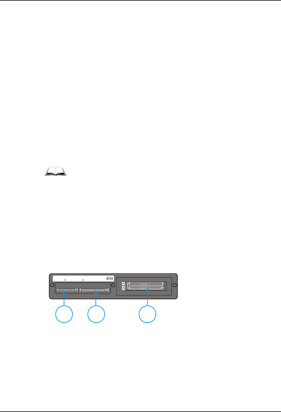
PCMCIA, ATA and SD Slots
The VX6 has two PCMCIA slots. These slots are intended for use with Type I or II cards, such as
LXE’s 2.4GHz radios. These slots are hot swappable per PCMCIA specifications.
The Compact Flash (CF) slot contains the Compact Flash ATA hard drive. This drive contains
the Operating System and the Documents and Settings. The VX6 does not operate without this
card installed. The CF card is not hot swappable.
One Secure Digital (SD) slot is provided for SD memory cards. The SD card is hot swappable.
SD CF ATA
PCMCIA A
PCMCIA B
21 3
1. SD Memory Card Slot
2. Compact Flash ATA Hard
Drive
3. PCMCIA Slots
Figure 7 The VX6 PCMCIA, CF and SD Slots
Please see the “VX6 Reference Guide” for more details on the PCMCIA, CF and SD slots.
10 AppLock and the VX6
VX6 User’s Guide E-EQ-VX6OGWW-F
AppLock and the VX6
AppLock may be installed and running on the mobile device. AppLock restricts access to
programs and the Windows CE Control Panel. Please contact your system administrator for
details.
Single Application AppLock
Single application AppLock restricts a user to one application. The user is unable to exit the
application (or if the application exits, it immediately restarts).
Note: Single application AppLock is obsolete. Please contact your LXE representative if you
desire to upgrade to multi application AppLock.
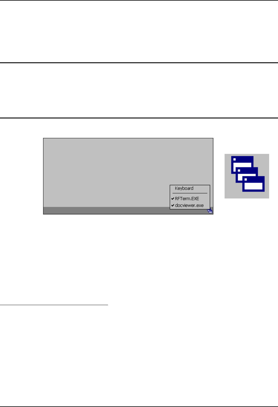
Multi Application AppLock
Switchpad Menu Switchpad Icon in
Taskbar
Figure 8 Switchpad Menu
A checkmark indicates applications currently active or available for Launching by the user. When
Keyboard is selected, the VX6 default input method (Input Panel, Transcriber, or custom input
method) is activated.
Note: If “Keyboard” is not present in the window, an older version of AppLock is installed.
Please contact your LXE representative for upgrade information, if desired.
Using the Touchscreen
Note: The touch screen must be enabled.
When the mobile device enters end-user mode, a Switchpad icon (it looks like three tiny windows
one above the other) is displayed in the taskbar. The taskbar is always visible on top of the
application in focus.
When the user taps the Switchpad icon, a menu is displayed showing the applications available to
the user. The user can tap an application name in the popup menu and the selected application is
brought to the foreground. The previous application continues to run in the background. Stylus
taps affect the application in focus only. When the user needs to use the Input Panel, they tap the
Keyboard option. Input Panel taps affect the application in focus only.

AppLock and the VX6 11
E-EQ-VX6OGWW-F VX6 User’s Guide
The figure shown above is an example and is shown only to aid in describing how the user can
switch between applications using a stylus.
Using the Keypad
One switch key sequence (or hotkey) is defined by the administrator for the end-user to use when
switching between locked applications. This is known as the Activation key. When the switch
key sequence is pressed on the keypad, the next application in the AppLock configuration is
moved to the foreground and the previous application moves to the background. The previous
application continues to run in the background. End-user key presses affect the application in
focus only.
See the VX6 Reference Guide for AppLock setup instruction.
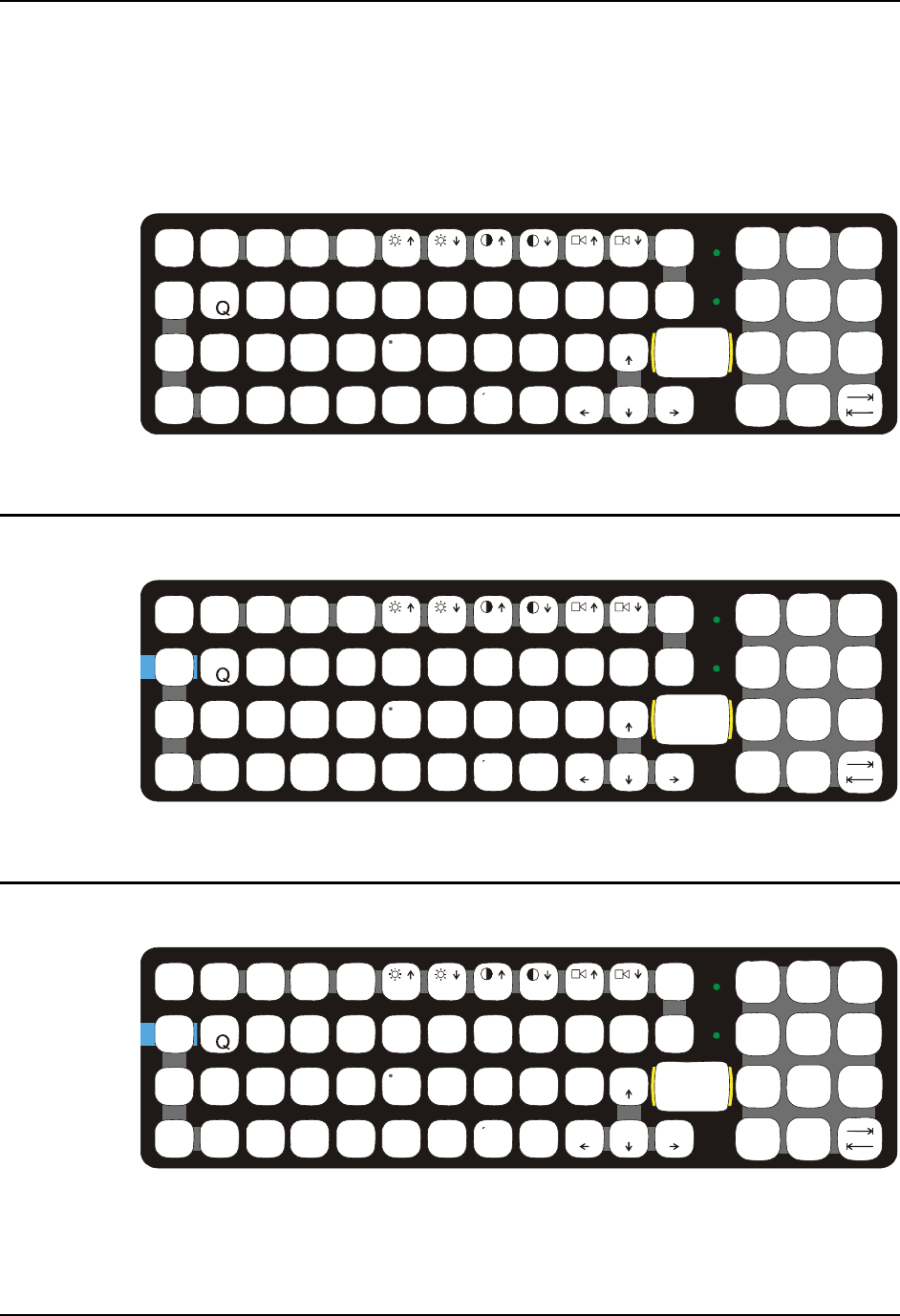
12 The QWERTY Keyboard
VX6 User’s Guide E-EQ-VX6OGWW-F
The QWERTY Keyboard
The VX6 has a QWERTY keyboard, available with a standard overlay, an IBM 3270 overlay or
an IBM 5250 overlay. These keyboards have 101 keyboard functions, including a numeric
keypad. Please refer to Appendix A, “Key Maps”, for keypress combinations.
ESC
SHIFT
2ND
ALT SP
F1 F2 F3 F4 F5 F6 F7 F8 F9
CAPS BREAK R/S
B
CMN
ADF
GHJKL
S
VXZ
@#$% ^&*()
F10
BKLT
INS
BKSP
EIO
P
RT
U
WY
CTRL !
|\ :; ‘,.?
~_
Home END
ENTER
PgUp
PgDn
0.
12
45
/78
-+
={}
[]>
<
DEL
3
6
9
CAPS
2nd
Figure 9 QWERTY Keyboard Standard
IBM 3270 Overlay
ESC
SHIFT
2ND
ALT SP
F1 F2 F3 F4 F5 F6 F7 F8 F9
CAPS BREAK R/S
B
CMN
ADF
GHJKL
S
VXZ
@#$%^&*()
F10
BKLT
INS
BKSP
EIOPRT
U
WY
CTRL !
|\ :; ‘,.?
~_
Home END
ENTER
PgUp
PgDn
0.
12
45
/78
-+
={}
[]>
<
DEL
3
6
9
Attn SysReq Del
Clr NL
Ins E-Inp
CAPS
2nd
Rst
PA1 PA2 PA3
Figure 10 QWERTY Keyboard with IBM 3270 Overlay
IBM 5250 Overlay
ESC
SHIFT
2ND
ALT SP
F1 F2 F3 F4 F5 F6 F7 F8 F9
CAPS BREAK R/S
B
CMN
ADF
GHJKL
S
VXZ
@#$%^&*()
F10
BKLT
INS
BKSP
EIOPRT
U
WY
CTRL !
|\ :; ‘,.?
~_
Home END
ENTER
PgUp
PgDn
0.
12
45
/78
-+
={}
[]>
<
DEL
3
6
9
Attn SysReq Del
Clr
Dup
NL
Ins
Fld+
Fld-
E-Inp
Field Exit
CAPS
2nd
Figure 11 QWERTY Keyboard with IBM 5250 Overlay
Note: Press the <CTRL> + <Enter> keys to initiate the IBM 5250 Field Exit Function.

The QWERTY Keyboard 13
E-EQ-VX6OGWW-F VX6 User’s Guide
Key Maps
The keyboard supports all 101 keyboard functions. However, because the keyboard only has 60
keys, all functions are not visible (or printed on the keyboard). Therefore the VX6 keyboard
supports what is called hidden keys -- keys that are accessible but not visible on the keyboard.
The hidden keys supported by the VX6 are listed in Appendix A, “Key Maps”.
Unused Key Functions
There are several key functions on the keyboard that are not used on the VX6. These include:
• <2nd> <F3> – The Resume/Suspend function is not used, as the VX6 does not
support these power management modes.
• <2nd> <F4> and <2nd> <F5> – The Display Brightness functions are not used as
the display brightness is adjusted by the buttons on the VX6 control panel.
• <2nd> <F6> and <2nd> <F7> – The Contrast functions are not used as the contrast
is not adjustable on the TFT display on the VX6.
• <2nd> <F8> and <2nd> <F9> – The Volume control keys are not used as volume is
adjusted via the Microsoft Windows CE Control Panel.
• <2nd> <F10> – The keyboard backlight in controlled by Windows CE Power
Management.
Custom Key Maps
The System Administrator creates Custom Key Maps for the VX6. To activate the Custom
keymap, select Start | Settings | Control Panel | Keyboard icon. Select the Custom keymap from
the keyboard popup menu, and close the control panel with the OK button.
To return to the default keymap, select 0409 or Preload, depending on system version, from the
keymap popup and click OK.
NumLock and the VX6
The keyboard does not have a NumLock indicator or key. By default, the VX6 turns NumLock
On each time the VX6 is turned on.
NumLock can be toggled On or Off using the <2nd> <SHIFT> <F10> keypress sequence.
The warmboot behavior of NumLock can be configured. Please refer to the “VX6 Reference
Guide” for more information on NumLock.
Keyboard Backlight
The LXE keyboard keys are backlit. The keyboard backlight and the display share the same
timer, which is configured in the Windows CE Control Panel. When the display is On, the
keyboard backlight is also On. Please refer to Control Panel Options in the “VX6 Reference
Guide” for more information.
14 The QWERTY Keyboard
VX6 User’s Guide E-EQ-VX6OGWW-F
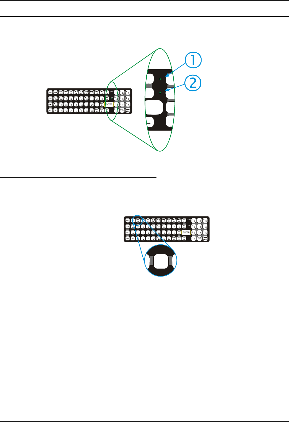
Keyboard LEDs
The VX6 keyboard has two (2) LED indicators.
CAPS
2nd
INS
BKSP
ENTER
END
F10
KLT
0
1
4
/7
=
[
<
1. CapsLock Mode LED
Indicator
2. Secondary Mode
LED Indicator
Figure 12 Keyboard LEDs
CAPS LED
This LED indicates the state of the keyboard CapsLock mode. If CapsLock is enabled this LED is
illuminated green. When CapsLock is off, the LED is dark.
B
D
CAPS
F1
Figure 13 The CapsLock Key
Press <2nd> then <F1> to toggle CapsLock On and Off.
The default value of CapsLock is “Off”. For information on configuring the behavior of
CapsLock after a reboot, please refer to the “VX6 Reference Guide”.

The QWERTY Keyboard 15
E-EQ-VX6OGWW-F VX6 User’s Guide
Secondary Keys LED
The keyboard is equipped with several secondary keys. These keys are identified by the
superscripted text found on the keyboard keys. The secondary keys are accessible by using two
(2) keystrokes: the <2nd> key followed by the superscripted key.
C
C2ND
Figure 14 The Secondary Key
Once the <2nd> state is enabled (by pressing the <2nd> key) the Secondary Mode LED is
illuminated and the <2nd> state is enabled until another key is pressed. The <2nd> key is toggled on
with a <2nd> keypress and then immediately off with another <2nd> keypress.
For example:
Press <2nd> and <F1> to turn CapsLock on and off.
Press <2nd> and <↑> to initiate the PgUp command.
Press <2nd> and <Q> to type the “!” key.
Press <2nd> and <BkSp> to enter the Insert (Ins) mode.
16 The QWERTY Keyboard
VX6 User’s Guide E-EQ-VX6OGWW-F
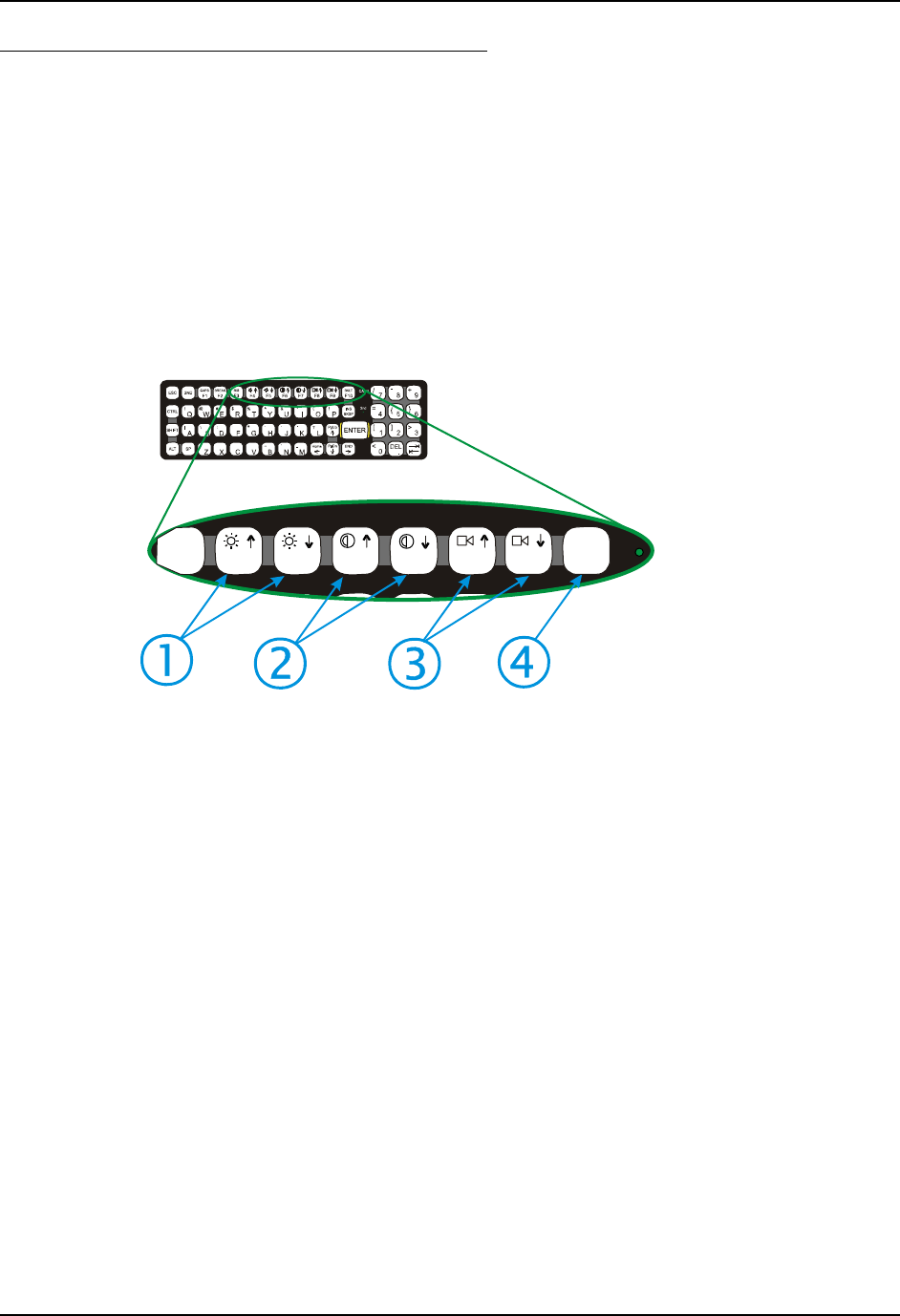
Control Keys
The keyboard has several control keys, which are not used on the VX6.
Note: The 2nd functions of the <F4> and <F5>keys are not used as the display brightness is
adjusted via the buttons on the control panel.
The 2nd functions of the <F6>, and <F7> keys are not used as the VX6 has TFT LCD
screen with no provision for contrast adjustments.
The 2nd functions of the <F8> and <F9> keys are not used as the sound volume on the
VX6 is controlled with the Volume and Sounds icon in the Microsoft Windows CE .NE
Control Panel.
The 2nd function of the <F10> key is not used as the display backlight timer also controls
the keyboard backlight.
R/S
F3 F4 F5 F6 F7 F8 F9
BKLT
F10
1. Display Brightness
Control Keys (Not
used)
2. Display Contrast
Control Keys (Not
used)
3. Speaker Volume
Control Keys (Not
used)
4. Backlight Control
Key (Not Used)
Figure 15 Keyboard Display Controls

The QWERTY Keyboard 17
E-EQ-VX6OGWW-F VX6 User’s Guide
General Windows CE Keyboard Shortcuts
Use the keyboard shortcuts in the chart below to navigate with the VX6 keyboard. These are
standard keyboard shortcuts for Windows CE applications.
Press these keys … To …
CTRL + C Copy
CTRL + X Cut
CTRL + V Paste
CTRL + Z Undo
DELETE Delete
SHIFT with any of the arrow keys Select more than one item in a window or on the
desktop, or select text within a document.
CTRL+A Select all.
ALT+ESC Cycle through items in the order they were opened.
CTRL+ESC Display the Start menu.
ALT+Underlined letter in a menu
name Display the corresponding menu.
Underlined letter in a command
name on an open menu Carry out the corresponding command.
ESC Cancel the current task.
The touchscreen provides equivalent functionality to a mouse:
• A touch on the touchscreen is equivalent to a left mouse click.
• Many items can be moved by the “drag and drop” method, touching the desired item,
moving the stylus across the screen and releasing the stylus in the desired location.
• A double stylus tap is equivalent to a double click.
• A touch and hold is equivalent to a right mouse click.
18 The QWERTY Keyboard
VX6 User’s Guide E-EQ-VX6OGWW-F
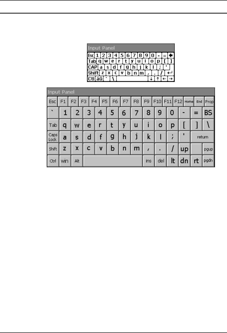
Input Panel (Virtual Keyboard)
The Input Panel may be enabled via the Input Panel icon in the Windows CE Control Panel. The
Input Panel can be displayed as a large or small keyboard.
Figure 16 Small and Large Virtual Keyboards
Virtual keyboards display the actual character a keypress results in. For example, pressing the
<Shift> key on the virtual keyboard toggles the characters displayed on the keys between upper
and lower case. The <áü> key toggles the keys between standard and international symbols. The
<Shift> and <áü> keys can be used in combination for capitalized international characters.
Note: When the virtual keyboard is displayed, the physical keyboard is still active. Therefore it
is possible to input data from both keyboards.
The QWERTY Keyboard 19
E-EQ-VX6OGWW-F VX6 User’s Guide
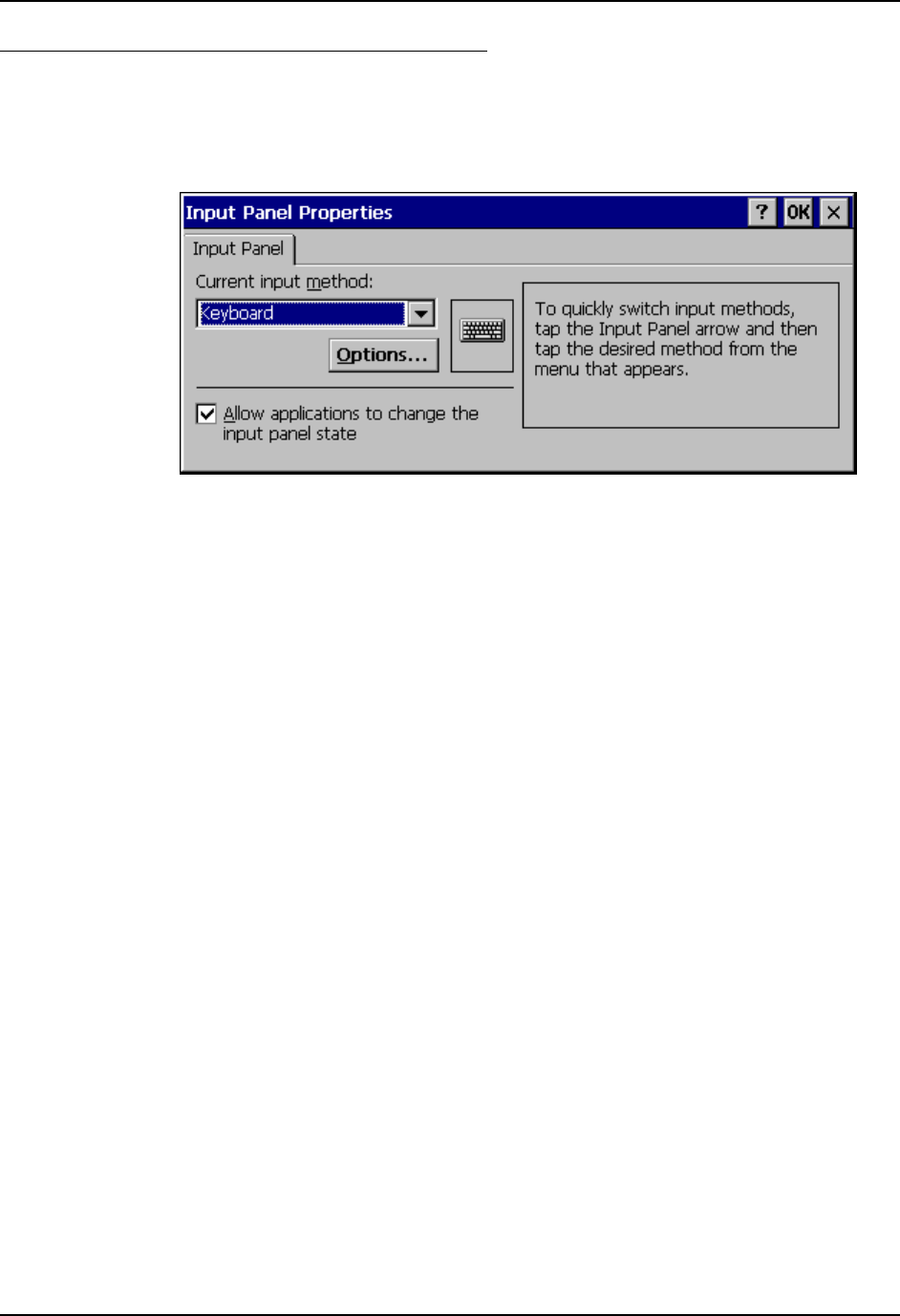
Enabling the Input Panel
The Input Panel is disabled by default. To enable the Input Panel, select Start | Settings |
Control Panel |Input Panel icon. Make sure the “Allow applications to change the input panel
state” checkbox is checked and warmboot the VX6.
Figure 17 Input Panel Properties
20 Power Supply
VX6 User’s Guide E-EQ-VX6OGWW-F
Power Supply
Vehicle power input for the VX6 is 12V to 80V DC and is accepted without the need to perform
any manual adjustments within the VX6. See the section titled “Installation”, sub-section titled
“Vehicle 12-80V DC Direct Connection”. An optional Uninterruptible Power Supply (UPS)
battery pack is available for the vehicle power supply connection.
If 12V to 80V DC power is not available – for example, in an office environment – an optional
external Input Power Supply can be used to convert AC wall power to an appropriate DC level.
See the section titled “Installation”, sub-section titled “External Power Supply”.
Power input is fused for protection and the fuse is externally accessible. See section titled
“Installation”, sub-section titled “Fuse Replacement for the VX6”.
Uninterruptible Power Supply Battery Pack
An optional Uninterruptible Power Supply (UPS) battery pack is designed to provide power to the
VX6 for short periods of time when vehicle power is unavailable (such as when vehicle batteries
are swapped). Fully charged, the UPS battery powers the VX6 for a minimum of 15 minutes at
25º C (77º F) ambient temperature.
The Power Status LED on the VX6 indicates the UPS battery status:
Green – Running on 12V – 80V power input
Solid Yellow – Running on UPS battery, battery is not low on power
Flashing Yellow – Running on UPS battery, battery is critically low.
Backup Battery
The internal 190 mAh Lithium backup (coin cell) battery provides power to maintain date and
time when the VX6 is not powered from an external source.
Caution
!
Danger of explosion if battery is incorrectly replaced.
Replace only with the same type or equivalent type recommended by the
manufacturer.
Dispose of used batteries according to the manufacturer’s instructions.

Getting Help 21
E-EQ-VX6OGWW-F VX6 User’s Guide
Getting Help
All LXE manuals are now available on one CD and they can also be viewed / downloaded
from the LXE ServicePass website on the ServicePass / Documentation page. Contact your LXE
representative to obtain the LXE Manuals CD or logon information for the ServicePass web
pages.
You can also get help from LXE by calling the telephone numbers listed on the LXE Manuals
CD, in the file titled “Contacting LXE”. This information is also available on the LXE website.
Explanations of terms and acronyms used in this guide are located in the file titled “Glossary” on
the LXE Manuals CD.
Manuals and Accessories
Manuals
The following manuals are available on the LXE Manuals CD:
• VX6 Reference Guide
• Contacting LXE
• LXE Technical Glossary
Accessories
The table below lists the available VX6 accessories.
• Where two parts numbers are listed for a given part, the part number ending in “-R”
is the RoHS compliant version.
• When only one part number is listed, the part is RoHS compliant unless otherwise
noted.
VX6 Brackets
Bracket, U Style, VX6 VX77 9000A021UBRACKET-R
Kit, VXX U-Bracket to VX6 VX7 Adapter 9000A022BRKTADPTKIT-R
Bracket, RAM Mount VX6 VX7 9000A023BRKTRAMMOUNT-R
Bracket, VXX RAM ball on plate 9000A028RAMPLATEBALL-R
Bracket, RAM Squeeze Mount, VX6 VX7 9000A031BRKTRAMSQZMT-R
Bracket, RAM Backup Mounting Plate 90000A033BACKUPPLATE
Data Cables
Cable, Combo D15 to USB and Ethernet Adapter 1 Ft 9000A071CBLD15USBETH
Cable, Combo D15 to USB-H, USB-C and Ethernet Adapter 9000A075CBLUSBHCETH
Cable, Printer/PC, D9 to D25 9000A053CBL6D9D25
(above part is not RoHS compliant)
Cable, PC, D9 to D9 9000A054CBL6D9D9

22 Manuals and Accessories
VX6 User’s Guide E-EQ-VX6OGWW-F
Power Cables
Cable, Input Power, 12 FT, VX5 VX6 VX7 9000A073CBLPWR12FT-R
Adapter Cable, VX1 VX2 VX4 Power Cable to VX5 VX6 VX7 9000A077CBLPWRADPTR
Power Supplies
Power Supply, External, AC, W/US Power Cord VX5 VX6 VX7 9000A317PSACUS-R
Power Supply, External, AC, No Power Cord VX5 VX6 VX7 9000A318PSACWW-R
UPS Battery and Cables
Battery, UPS Lead Acid, VX5 VX6 VX7 9000A378UPSBATTPACK-R
Cable, UPS Battery, Remote Mount Extender, 6 Ft 9000A074CBLUPSEXTNDR
Antenna and Antenna Mount Kits
Replacement antenna, 2.4GHz 153180-0001
Remote Mount Antenna Assembly Kit, 8 Ft Cable 9000A279ANTREMOTE8-R
Remote Mount Antenna Assembly Kit, 6 Ft Cable 9000A278ANTREMOTE6-R
Right Angle Remote Mount Antenna Assembly Kit, 6 Ft Cable 9000A280ANTREMOTE6RT
Right Angle Remote Mount Antenna Assembly Kit, 15 Ft Cable 9000A281ANTREMOT15RT
Miscellaneous
Stylus, with Tethers and Sleeves, 5 Pack 9000A510STYLUS
Protective Film, Touchscreen, 10 Pack, VX6 VX6A512PROTFILM
Voice Recognition Accessories
Headset coiled adapter cable, with quick disconnect connector to a
2.5 mm audio jack. A headset (see below) is required 9000A076CBLHEADSET1
Headset, Single Band HX1A501SINGHEADSET
Headset, Dual Band HX1A502DUALHEADSET
Headset, Behind the Ear, Dual Ear HX1A503BTHHEADSET
Foam, Replacement Block, Headset HX1A504HSBLOCKFOAM
Yoke, Replacement for Dual Band Headset HX1A505DUALYOKE
Yoke, Replacement for Single Band Headset HX1A506SINGLEYOKE
Replacement Microphone Foam, Wind Screen, 10 pack HX1A508WINDSREEN10
Replacement Microphone Foam, Wind Screen, 50 pack HX1A509WINDSREEN50
Replacement Headset Foam, Ear Cover, 10 pack HX1A510FOAMEAR10
Replacement Headset Foam, Ear Cover, 50 pack HX1A511FOAMEAR

Manuals and Accessories 23
E-EQ-VX6OGWW-F VX6 User’s Guide
Scanners
Scanner, Powerscan, SR, 8’ Cbl, WW 8300A326SCNRPWRSR8DA9F
8300A326SCNRPWRSR8DA9F-R
Scanner, Powerscan, SR, 12’ Cbl, US 8300A327SCNRPWRSR12DA9F
(above part is not RoHS compliant)
Scanner, Powerscan, SR, Low Temp, 8’ Cbl 8300A332SCNRS8D9FLT
(above part is not RoHS compliant)
Scanner, Powerscan, SR, Low Temp, 12’ Cbl 8300A333SCNRS12D9FLT
(above part is not RoHS compliant)
Scanner, Powerscan, LR, 8’ Cbl, WW 8310A326SCNRPWRLR8DA9F
8310A326SCNRPWRLR8DA9F-R
Scanner, Powerscan, LR, 12’ Cbl, US 8310A327SCNRPWRLR12DA9F
8310A327SCNRPWRLR12DA9F-R
Scanner, Powerscan, LR, Low Temp, 8’ Cbl 8310A332SCNRL8D9FLT
(above part is not RoHS compliant)
Scanner, Powerscan, LR, Low Temp, 12’ Cbl 8310A333SCNRL12D9FLT
(above part is not RoHS compliant)
Scanner, Powerscan, XLR, 8’ Cbl, WW 8320A326SCNRPWRXLR8DA9F
8320A326SCNRPWRXLR8DA9F-R
Scanner, Powerscan, XLR, 12’ Cbl, US 8320A327SCNRPWRXLR12DA9F
(above part is not RoHS compliant)
Scanner, Powerscan, XLR, Low Temp, 8’ Cbl 8320A332SCNRX8D9FLT
(above part is not RoHS compliant)
Scanner, Powerscan, XLR, Low Temp, 12’ Cbl 8320A333SCNRX12D9FLT
(above part is not RoHS compliant)
Scanner, LS3408 Fuzzy Logic SR, D9 Interface Cable, 8ft 8510A326SCNRFZYDA9F
8510A326SCNRFZYDA9F-R
Scanner, LS3408 Extended Range, D9 Interface Cable, 8ft 8520A326SCNRERDA9F-R

24 Manuals and Accessories
VX6 User’s Guide E-EQ-VX6OGWW-F
Bluetooth Scanner and Accessories
PowerScan 7000BT Scanner RS-232 with pointer 8700A301SCNRBTSRI
PowerScan 7000BT Base Station, RS232, without universal
power supply. 8700A501BASERS232
PowerScan 7000BT Base Station Power Supply, Std US, 120V 8700A502PSACUS
PowerScan 7000BT, RS232 Cable for Base Station, DB9S, Coil,
8’ 8700A001CBL8DA9F
PowerScan 7000BT Battery Charger with Power Supply, Four
Station, US Std 8700A503CHGR4US
PowerScan 7000BT Battery Pack 8700A504BATT
Bluetooth Standard Range Fuzzy Logic laser scanner 8810A326SCNRBTFZ
Bluetooth Auto range “LORAX” scanner 8820A327SCNRBTER
Desk Cradle, Radio/Charging, Multi-Interface 8800A001CRADLERCMI
Desk Cradle, Charge Only, Mulit-Interface 8800A002CRADLECMI
Forklift Cradle, Radio/Charging, Multi-Interface 8800A003CRADLEVRCMI
Forklift Cradle, Charge Only, Multi-Interface 8800A004CRADLEVCMI
US AC Power Cord 8800A051POWERCORD
Universal Desktop Power Supply 90-264VAC 8800A301ACPS
9-60VDC Forklift Power Supply 8800A302DCPS
Power Cable (connects Power Supply to Forklift) 8800A052DCPWRCABLE
Cable Assembly, DA9F, 9 ft, Cradle to Terminal 8500A051CBL9DA9F
Forklift Rugged Scanner Holder with RAM mount 8800A005STAND
8800 Spare Battery 8800A376BATTERY
Single slot Universal Battery Charger Adapter Cup 8800A377CHGRADPTRCUP
Single Slot Battery Charger w/International Power 8800A378CHGR1SLOT
Universal Battery Charger, 4 slot. Requires 4 adapter cups 8800A379CHGRBASE
Scanner Holster for Belt 8200A501HOLSRBELT
Mounted take up Reel 8000A501INDREEL
Auto Sense Intellistand, Hands Free Scanning 8500A505STANDSMT
Strap with Scanner Clip 9000A411SCNRSTRAP

E-EQ-VX6OGWW-F VX6 User’s Guide
Installation
Install Mounting Brackets
Caution:
This device is intended to transmit RF energy. For protection against RF exposure
to humans and in accordance with FCC rules and Industry Canada rules, this
transmitter should be installed such that a minimum separation distance of at least
20 cm (7.8 in.) is maintained between the antenna and the general population.
This device is not to be co-located with other transmitters.
Equipment Needed: Phillips No. 1 screwdriver and a Torque wrench capable of measuring to 50
inch pounds (5.64±.56 N/m).
Note: Torquing tool is not supplied by LXE. Bolts, washers, and wrench needed when attaching
the bottom mounting bracket to the vehicle are not supplied by LXE.
Several types of mounting systems are provided for the VX6:
• RAM mount system:
o Available RAM ball base or RAM clamp mount
• U-Bracket system:
o Provision for integrated UPS battery mount
o Available without U-Bracket for vehicles previously equipped with an LXE
vehicle mounted computer
• Remote mount for UPS battery pack
Before installation begins, verify you have the applicable vehicle mounting bracket assembly
components necessary for your mount type, as shown in the following figures.
26 Install Mounting Brackets
VX6 User’s Guide E-EQ-VX6OGWW-F
RAM Mount System
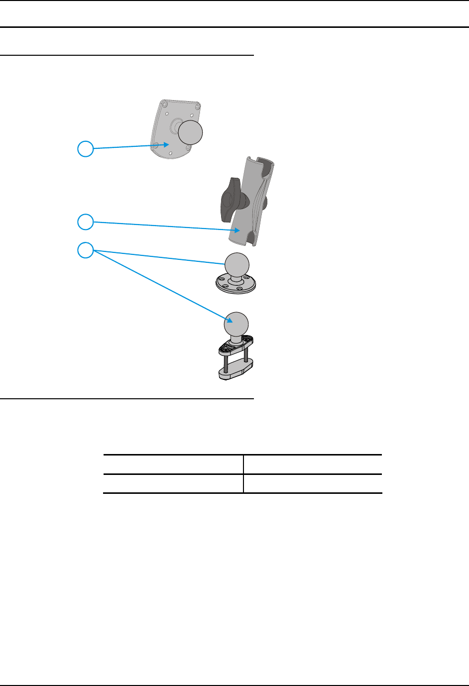
Components
RAM Mounting Assembly
The RAM mounting assembly consists of
the following parts:
1. VXX RAM ball bracket
2. RAM arm, size D
3. RAM ball base
- or -
RAM clamp mount
RAM Clamp Mount includes:
Upper Clamp Piece with Ball
Lower Clamp Piece
Bolts (2 each)
Nylon locking nuts (2 each)
2
1
3
- or -
4. Hardware (not shown):
Bolts, 1/4-20x5/8 (4 each)
Washers, 1/4 locking (4 each)
Washers, 1/4 flat (4 each)
RAM wrench
Torque Measurements
You will need a torquing tool capable of torquing to 50 inch pounds (5.64±.56 N/m).
Torque all screws and bolts according to the following table:
For these screws and bolts… Torque to
1/4 bolts 50.0±5 in/lb (5.64±.56 N/m)
Install Mounting Brackets 27
E-EQ-VX6OGWW-F VX6 User’s Guide
Procedure
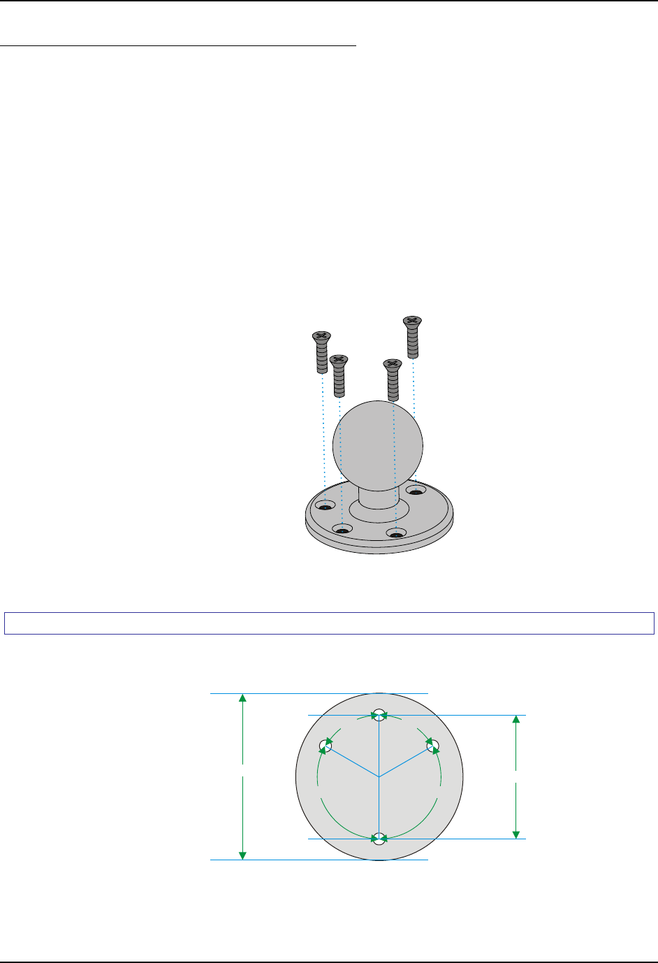
Step 1a – Mount Vehicle RAM Ball Base
Note: If you are using the RAM clamp mount, please skip to Step 1b.
1. Determine the position for mounting the RAM ball base. Be sure to position the RAM
ball base to allow access to the switches and ports on the bottom of the VX6.
2. Attach the RAM ball base to the vehicle mounting surface using four 1/4 bolts (or
equivalent) fasteners.
Note: 1/4 bolts not included.
IMPORTANT: Mount to the most rigid surface available.
Figure 18 Connect Vehicle RAM Mount Bracket to Vehicle
Mounting Dimensions
Note: Drill and tap holes for 1/4 bolts.
120º120º
60º60º
2.75" / 69.85 mm
3.69" / 93.73 mm
Figure 19 VX6 RAM Bracket - Mounting Dimensions (Not To Scale)
28 Install Mounting Brackets
VX6 User’s Guide E-EQ-VX6OGWW-F
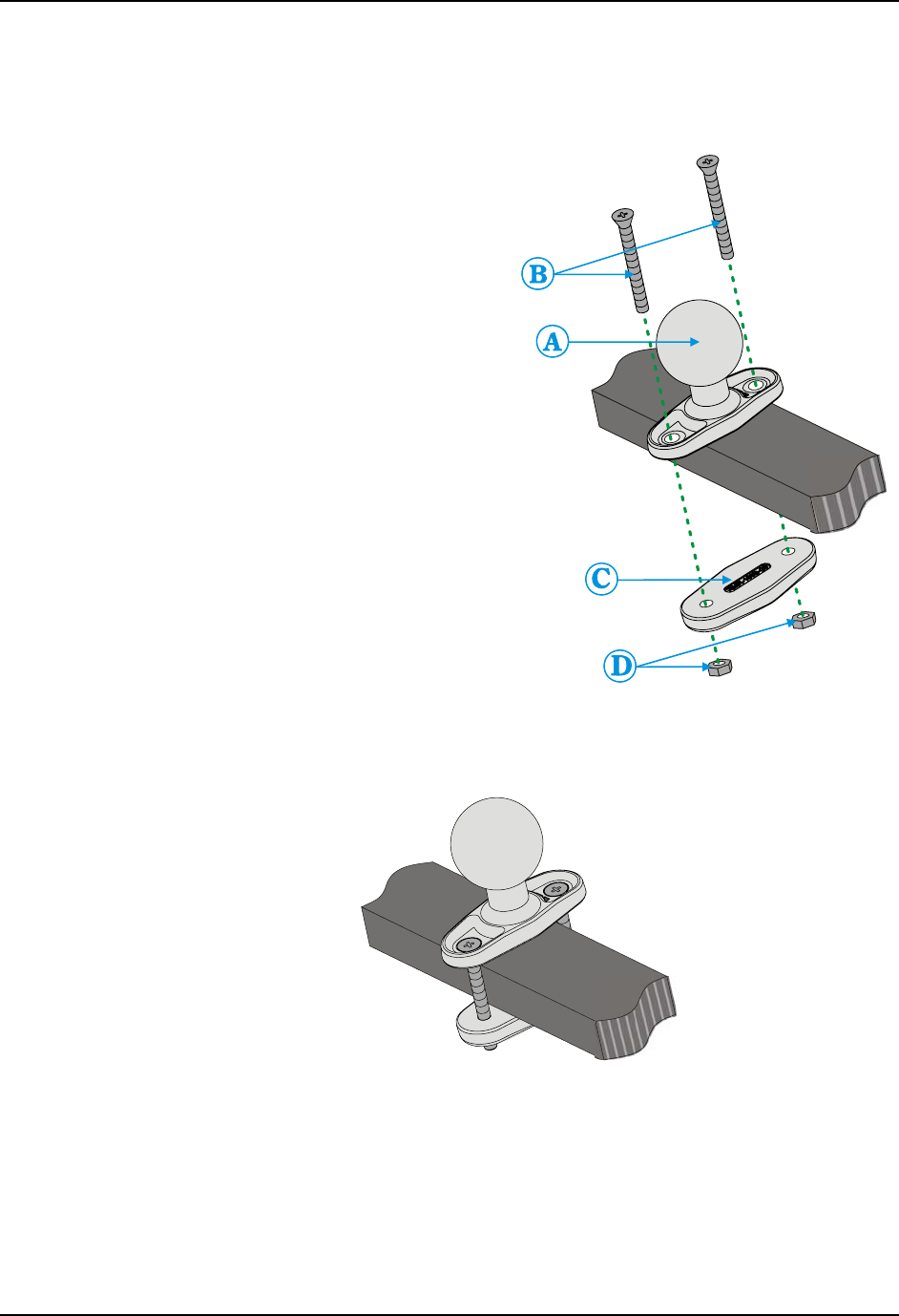
Step 1b – Mount Vehicle RAM Clamp Mount
Note: If you are using the RAM ball base, complete Step 1a and skip Step 1b.
1. Determine the position for mounting
the RAM clamp mount. The clamp
mount can be used on a beam (such
as on a fork lift truck) up to 2.5”
(63.5 mm) wide and approximately
2” (50.8 mm) thick. The clamp may
be attached to a thicker beam by
substituting longer bolts (not
included). Be sure to position the
RAM clamp mount to allow access
to the switches and ports on the
bottom of the VX6.
2. Position the upper clamp piece with
ball (A) on the beam. Place the bolts
(B) through the holes in the upper
clamp piece.
3. Position the lower clamp piece (C)
below the beam. Align the bolts with
the holes in the lower clamp piece.
4. Place the nylon locking nuts (D) on
the bolts and tighten the bolts.
Figure 20 RAM Clamp Mount
Components
Figure 21 Assembled RAM Clamp Mount

Install Mounting Brackets 29
E-EQ-VX6OGWW-F VX6 User’s Guide
Mounting Dimensions
A 2.56” (65.02 mm)
B 1.84” (46.74 mm)
Varies depending on bolt length
Figure 22 RAM Clamp Mount - Mounting Dimensions (Not To Scale)
30 Install Mounting Brackets
VX6 User’s Guide E-EQ-VX6OGWW-F
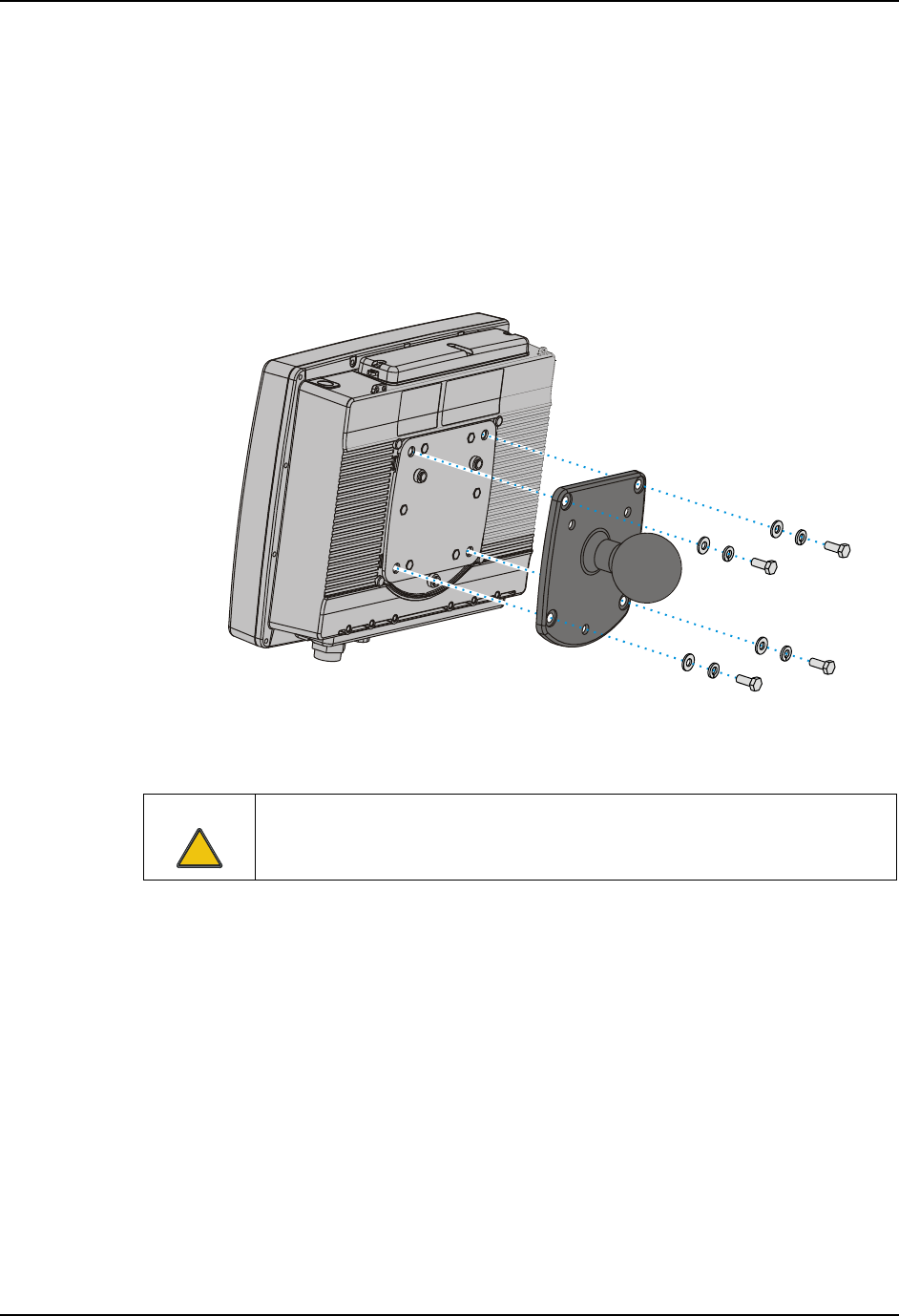
Step 2 – Attach RAM Mount Ball to the VX6
1. Turn the VX6 off before attaching the RAM mount ball.
2. Place the VX6 face down on a stable surface.
3. Position the RAM ball bracket on the rear of the VX6, aligning the curved edge on the
RAM mount bracket with the curved edge on the VX6. Attach with four 1/4-20x5/8
bolts, using one flat washer and one locking washer per bolt. Place the locking washer on
the bolt before the flat washer.
Figure 23 Attach RAM Mount to VX6
Caution
!
Failure to use one ¼ flat washer and one ¼ locking washer per bolt can result in
damage to the backplate of the VX6 computer.
Install Mounting Brackets 31
E-EQ-VX6OGWW-F VX6 User’s Guide
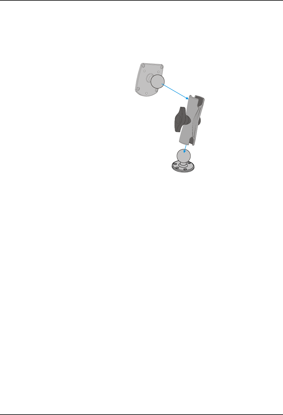
Step 2 – Attach VX6 Assembly to RAM Mount
1. Slip the RAM arm over the ball on the vehicle RAM ball bracket. Insert the ball of the
RAM mount bracket into the RAM arm. Adjust the VX6 to the desired position and
tighten the knob on the RAM arm using the supplied RAM wrench.
Figure 24 RAM Assembly
Note: RAM ball base shown.
32 Install Mounting Brackets
VX6 User’s Guide E-EQ-VX6OGWW-F
Completed Assembly
Figure 25 Completed RAM Mount Assembly
Note: RAM ball base shown.
Install Mounting Brackets 33
E-EQ-VX6OGWW-F VX6 User’s Guide
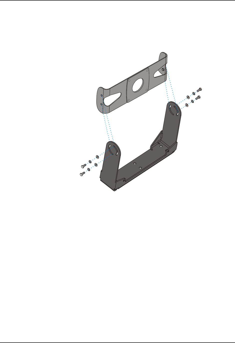
U-Bracket Mount System
Components
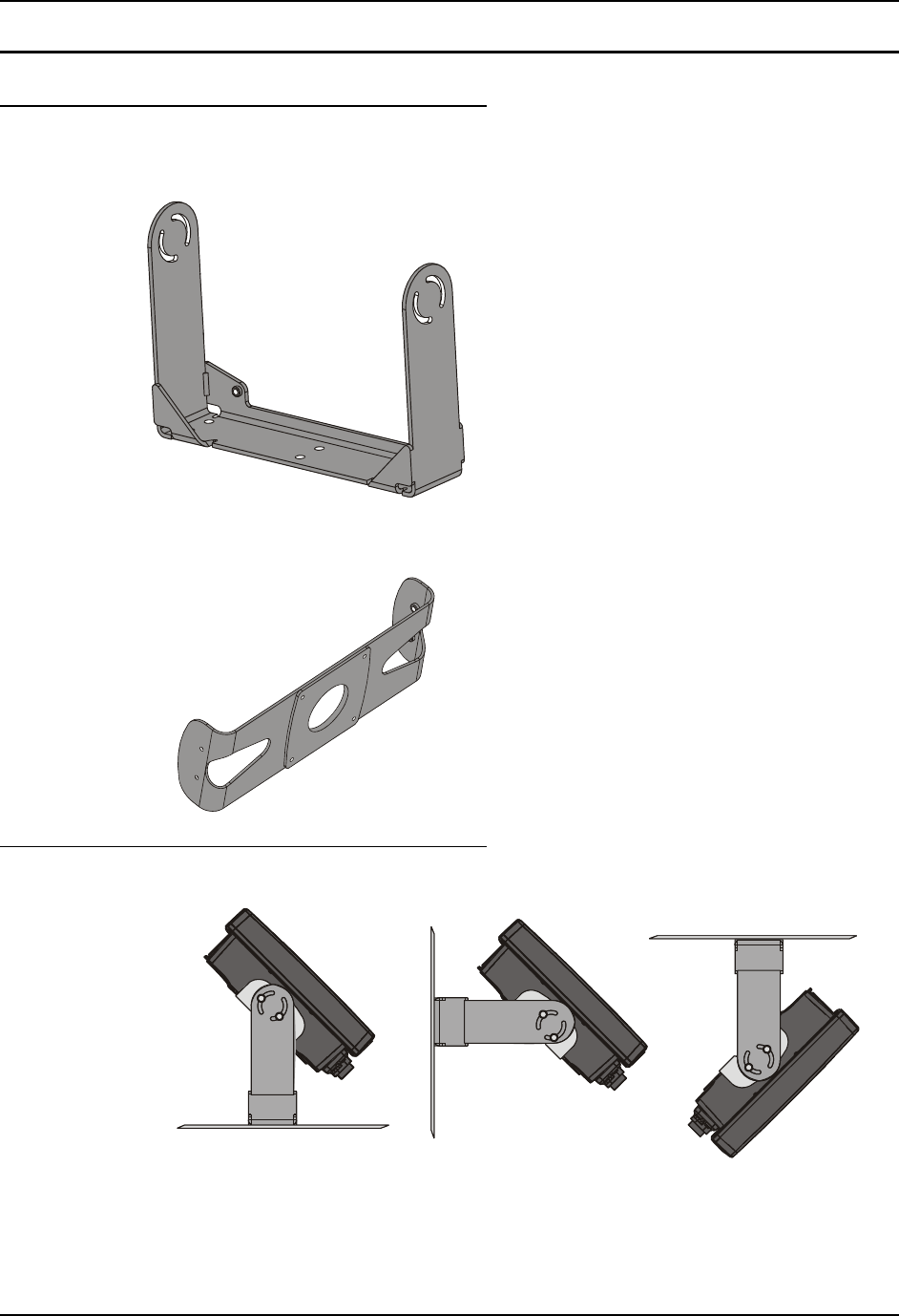
Bottom Mounting Bracket
This bracket is mounted to the vehicle. The VX6
can be mounted to the bottom mounting bracket.
The UPS battery pack may be mounted to the
bottom mounting bracket.
If the optional UPS battery pack is to be mounted
to the bottom bracket, use the following parts
included with the UPS battery pack (not shown):
1” long aluminum spacer w/through hole (2
each)
1/4 flat washer (2 each)
1/4 locking washer (2 each)
screw, pan head, 1/4-20x2 (2 each)
Back Bracket Assembly
1. Rear Bracket
2. Hardware (not shown):
1/4 flat washer (8 each)
1/4 locking washer (8 each)
1/4 flat washer (8 each)
Mounting Positions
Figure 26 Suggested Mounting Positions
The viewing angle can be adjusted through a wide range to provide the best viewing angle.

34 Install Mounting Brackets
VX6 User’s Guide E-EQ-VX6OGWW-F
Torque Measurements
You will need a torquing tool capable of torquing to 50 inch pounds (5.64±.56 N/m).
Torque all screws and bolts according to the following table:
For these screws and bolts… Torque to
1/4 bolts 50.0±5 in/lb (5.64±.56 N/m)
Install Mounting Brackets 35
E-EQ-VX6OGWW-F VX6 User’s Guide
Procedure
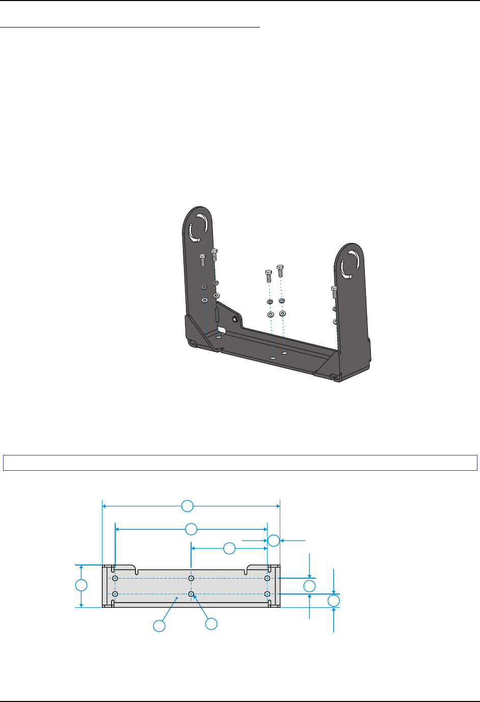
Step 1 - Mount Bottom Mounting Bracket To Vehicle.
1. Position the bracket to allow access to the switches and ports on the bottom of the VX6.
2. Attach the bottom mounting bracket to the vehicle mounting surface using a minimum of
four 1/4 bolts (or equivalent) fasteners.
Note: 1/4 bolts and washers not included. It is recommended to use lock washers and
flat washers on the fasteners.
IMPORTANT: Mount to the most rigid surface available.
Figure 27 Connect Bottom Bracket to Vehicle
After the bottom bracket has been attached to a rigid surface, you are ready to assemble the VX6
bracket configuration.
Mounting Dimensions
3
1
2
4
5
67
8
9
1. 14.40 in / 359.2 mm
2. 12.10 in / 307.3 mm
3. 6.05 in / 153.6 mm
4. 1.02 in / 25.9 mm
5. 3.38 in / 85.85 mm
6. Vehicle Mount
Footprint
7. 0.406 in / 10.312 mm
8. 0.88 in / 22.3 mm
9. 1.25 in / 31.75 mm
Figure 28 VX6 Bracket - Mounting Dimensions (Not To Scale)
36 Install Mounting Brackets
VX6 User’s Guide E-EQ-VX6OGWW-F
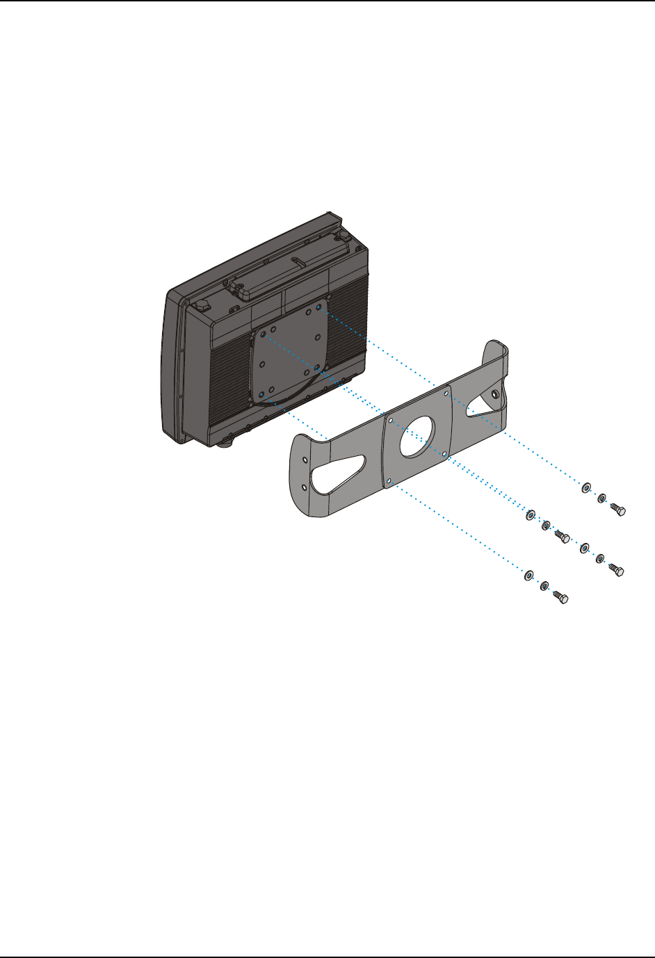
Step 2 - Connect Rear Bracket to VX6
1. Turn the VX6 off before attaching the rear bracket.
2. Place the VX6 face down on a stable surface.
3. Align the rear bracket with the holes on the back of the VX6. Attach with four 1/4-
20x5/8 bolts, using one flat washer and one locking washer per bolt. Place the locking
washer on the bolt before the flat washer.
Figure 29 Attach Rear Bracket to VX6
Install Mounting Brackets 37
E-EQ-VX6OGWW-F VX6 User’s Guide
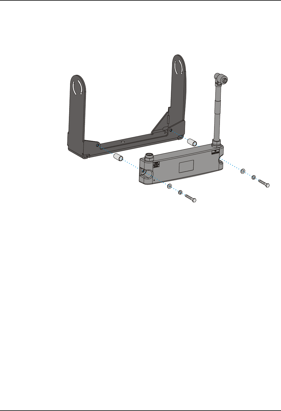
Step 3 - Attach VX6 Assembly To Bottom Mounting Bracket.
1. Place lock washer first, then flat washer on 1/4-20x5/8 bolt. Next insert mounting bolts
through the curved apertures in the bottom mounting bracket and into the screw holes on
the side of the back mounting bracket.
Figure 30 Attach VX6 Assembly to Bottom Bracket
2. Loosely tighten each bolt as it is inserted.
Important: Do not torque bolts until all bolts are in place and viewing angle
is adjusted.
3. Loosen the hex bolts on both sides to adjust the viewing angle of the mounted VX6.
4. Torque the hex bolts to 50±5 in lbf (5.64±.56 N m).
Note: Test the torque on the bolts frequently during operation and re-tighten if
necessary to 50±5 in lbf (5.64±.56 N m).
38 Install Mounting Brackets
VX6 User’s Guide E-EQ-VX6OGWW-F
6. If using a UPS battery pack, the battery pack can be mounted to the bottom mounting
bracket. Place a locking washer and then a flat washer on a 1/4-20x2 bolt. Thread the
bolt through the UPS Battery Pack, then through the 1” aluminum spacer and into the
mounting bracket.
Figure 31 Integrated UPS Battery Pack Mount
7. Connect all cables to the VX6. Secure the cables with the strain relief cable clamps,
ensuring a slack loop remains between the cable clamp and the accessory connector.
8. The vehicle mounted bracket and the VX6 are now ready to use.
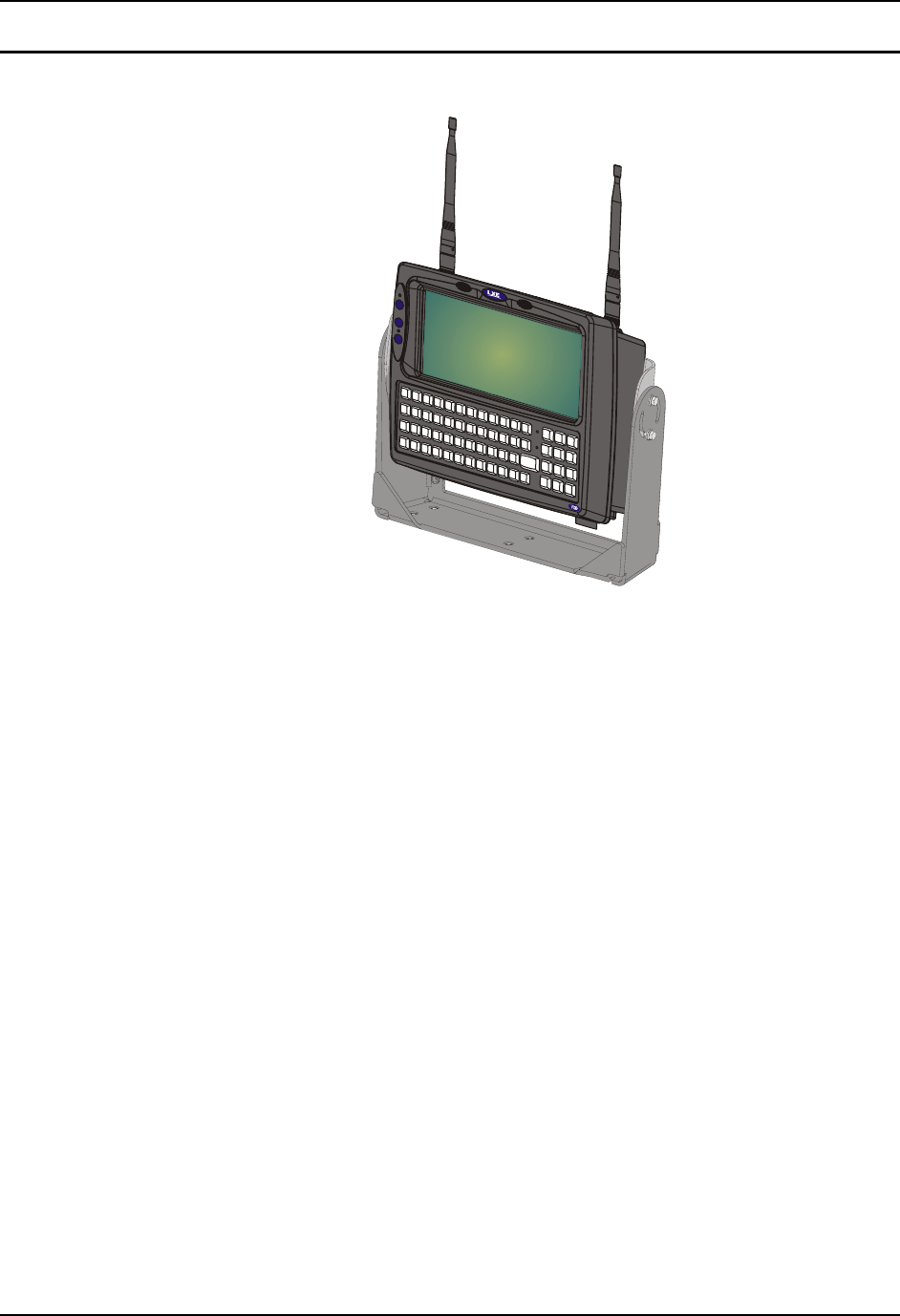
Install Mounting Brackets 39
E-EQ-VX6OGWW-F VX6 User’s Guide
Completed Assembly
Figure 32 VX6 in Vehicle Bracket
40 Install Mounting Brackets
VX6 User’s Guide E-EQ-VX6OGWW-F
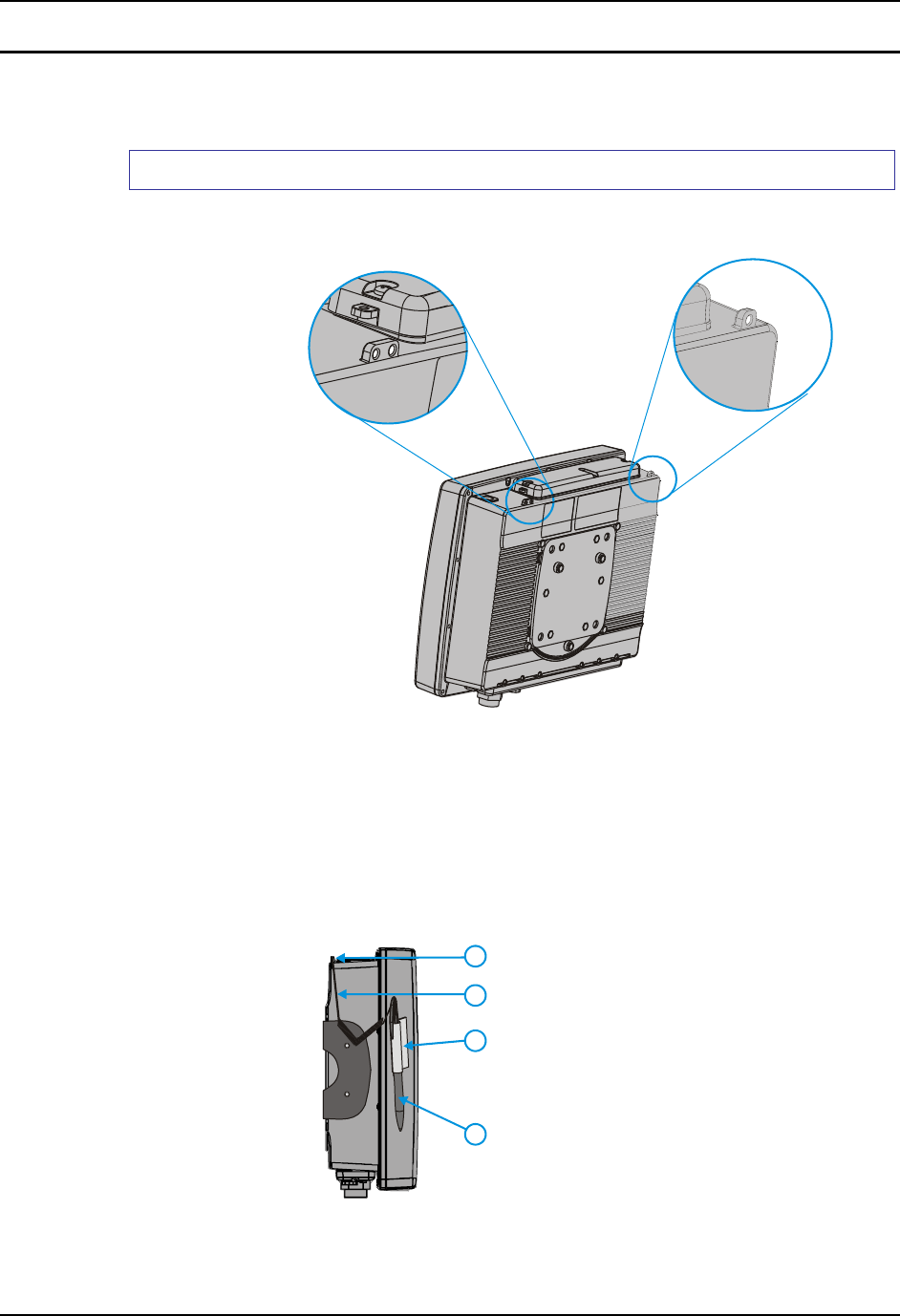
Install Stylus Tether and Sleeve
The LXE stylus kit includes the stylus, tether and sleeves. The tether allows the stylus to be
mounted to the VX6 and the sleeve provides storage for the stylus when not in use.
How To Install Stylus Tether and Sleeves
1. Locate the tether holes on the top of the VX6. (see below):
Figure 33 Stylus Tether Mounting Holes
2. Select the mounting hole most convenient for the particular VX6 installation.
3. Slide the clip end of the stylus tether into the tether mounting hole.
4. Determine a convenient location for the stylus sleeve. Apply the adhesive baked
Velcro® loop strip to the VX6. Attach the Velcro® hook strip on the elastic stylus
sleeve to the loop strip.
4
3
2
1
1 Tether Mount
2 Tether Cable
3 Stylus Sleeve
4 Stylus
Figure 34 Tethered Stylus, Typical Installation