Honeywell LXE4830P 802.11g COMPACT FLASH MODULE User Manual VX6 User s Guide
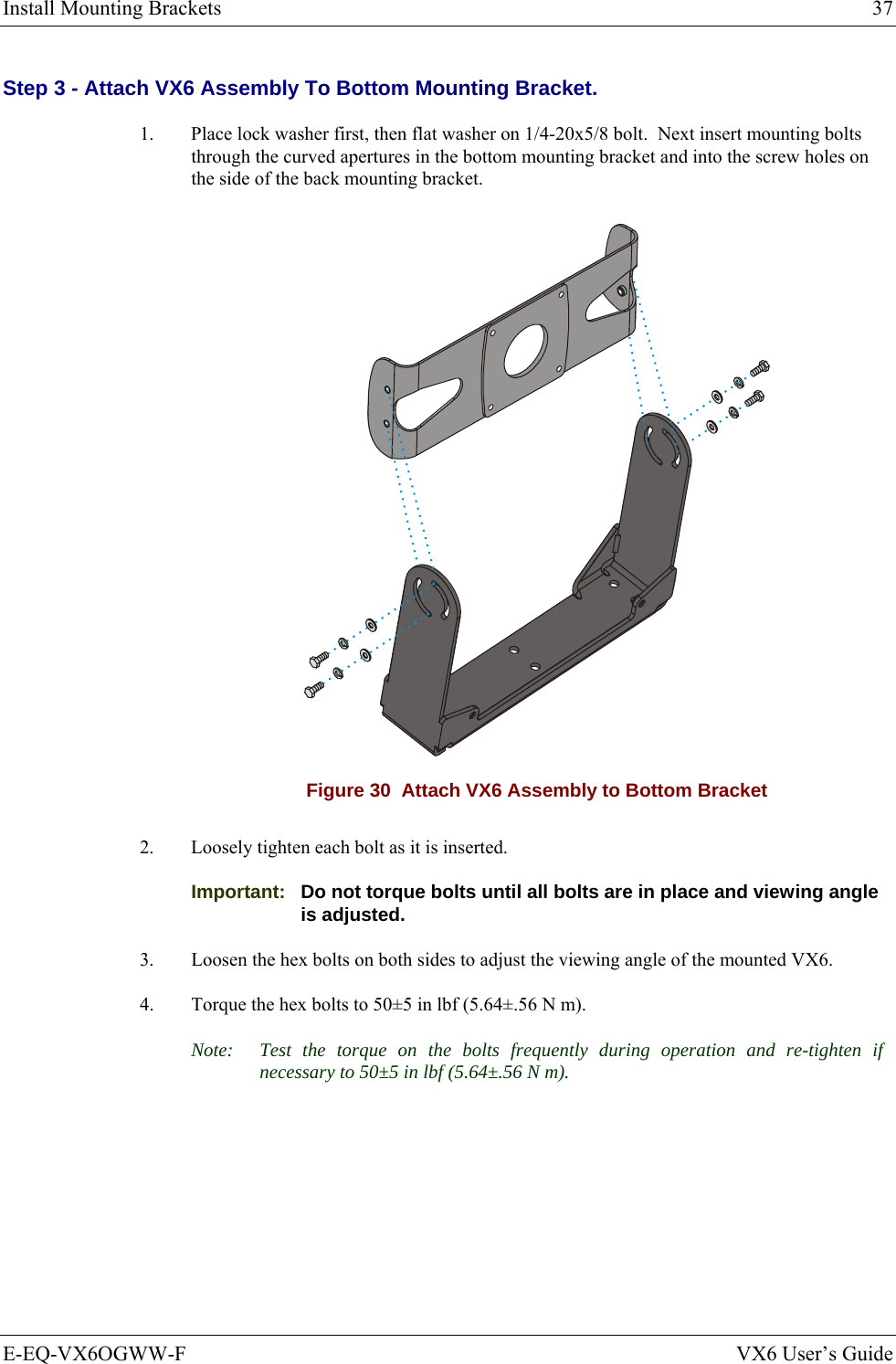
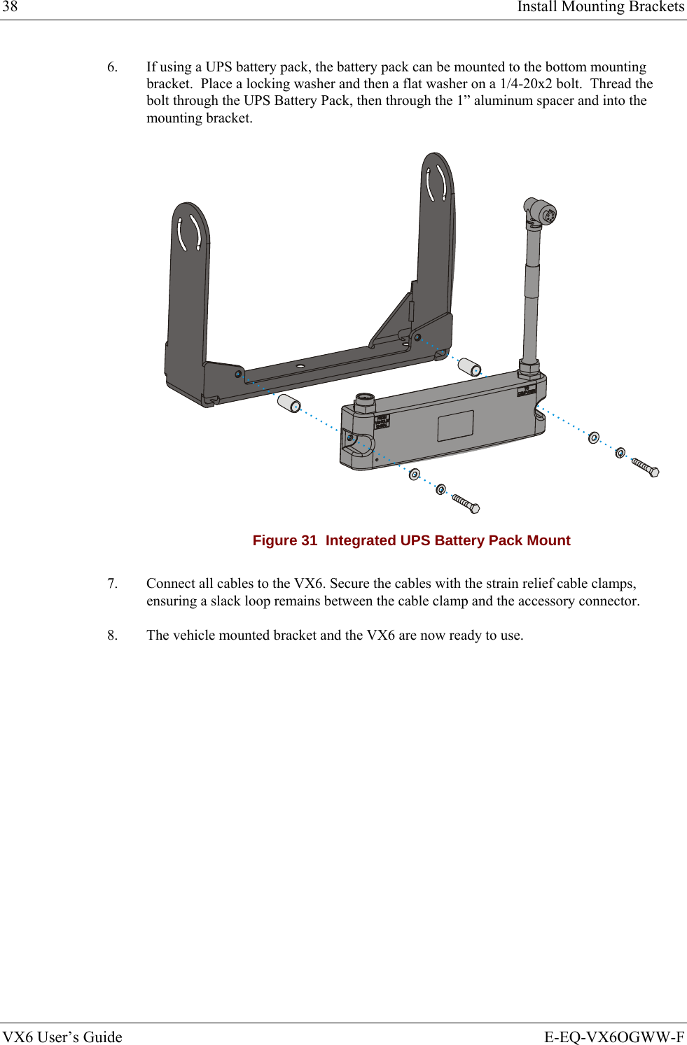
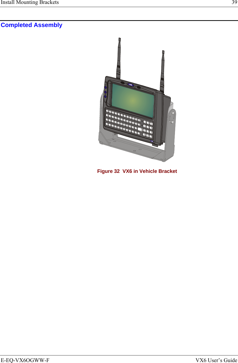
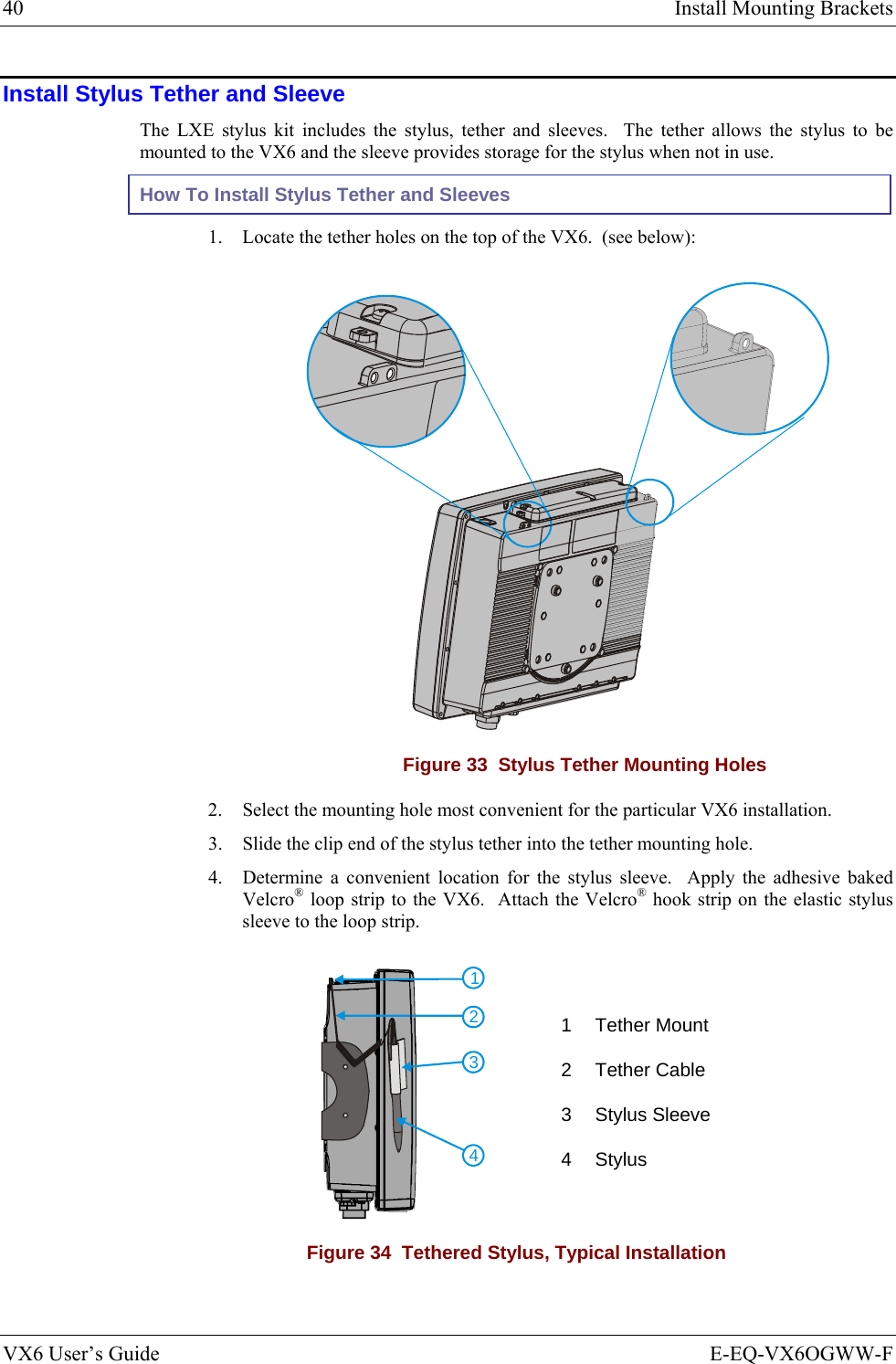
Honeywell International, Inc. 802.11g COMPACT FLASH MODULE VX6 User s Guide
Contents
- 1. Manual HX1 rev3
- 2. Manual MX3X rev3
- 3. Manual MX5X rev3
- 4. Manual MX7 rev3
- 5. User Manual HX2
- 6. User Manual MX7
- 7. users manual
- 8. USERS MANUAL
- 9. User Manual MX3X
- 10. User Manual VX3X
- 11. User Manual VX6 part 1
- 12. User Manual VX6 part 2
- 13. User Manual VX7 part 1
- 14. User Manual VX7 part 2
- 15. Users Manual F300
- 16. Users Manual MX9
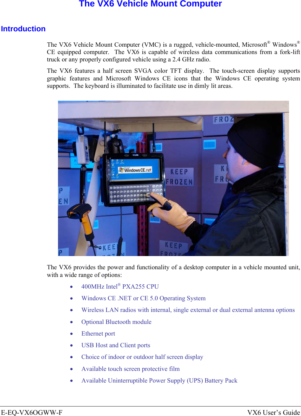
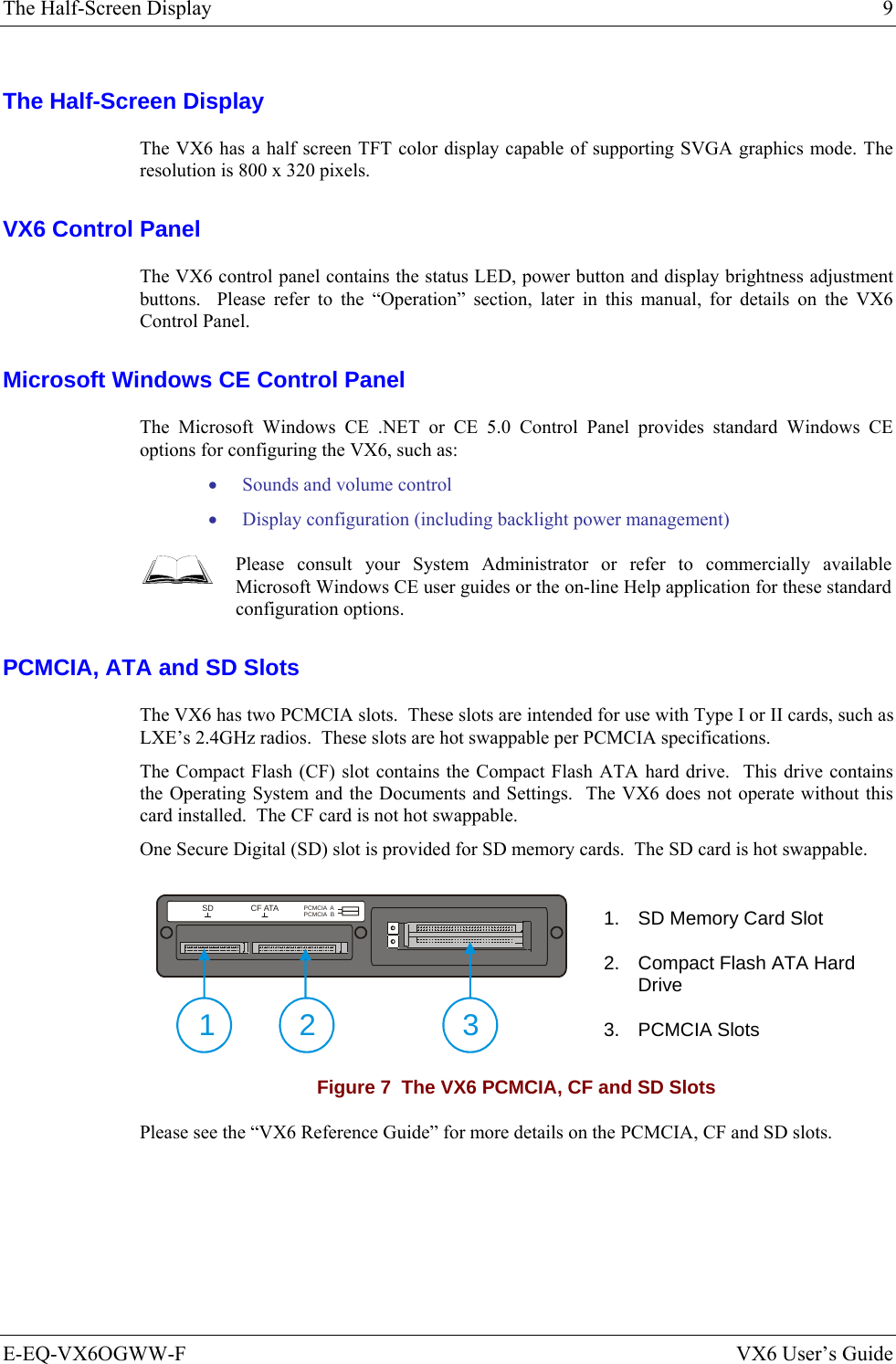
User Manual VX6 part 1
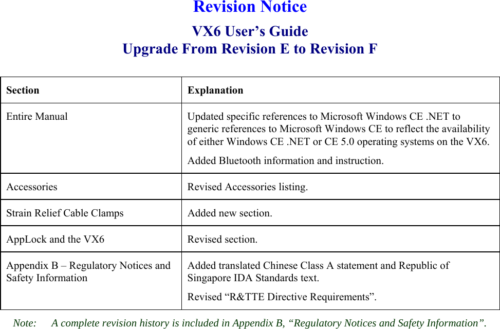

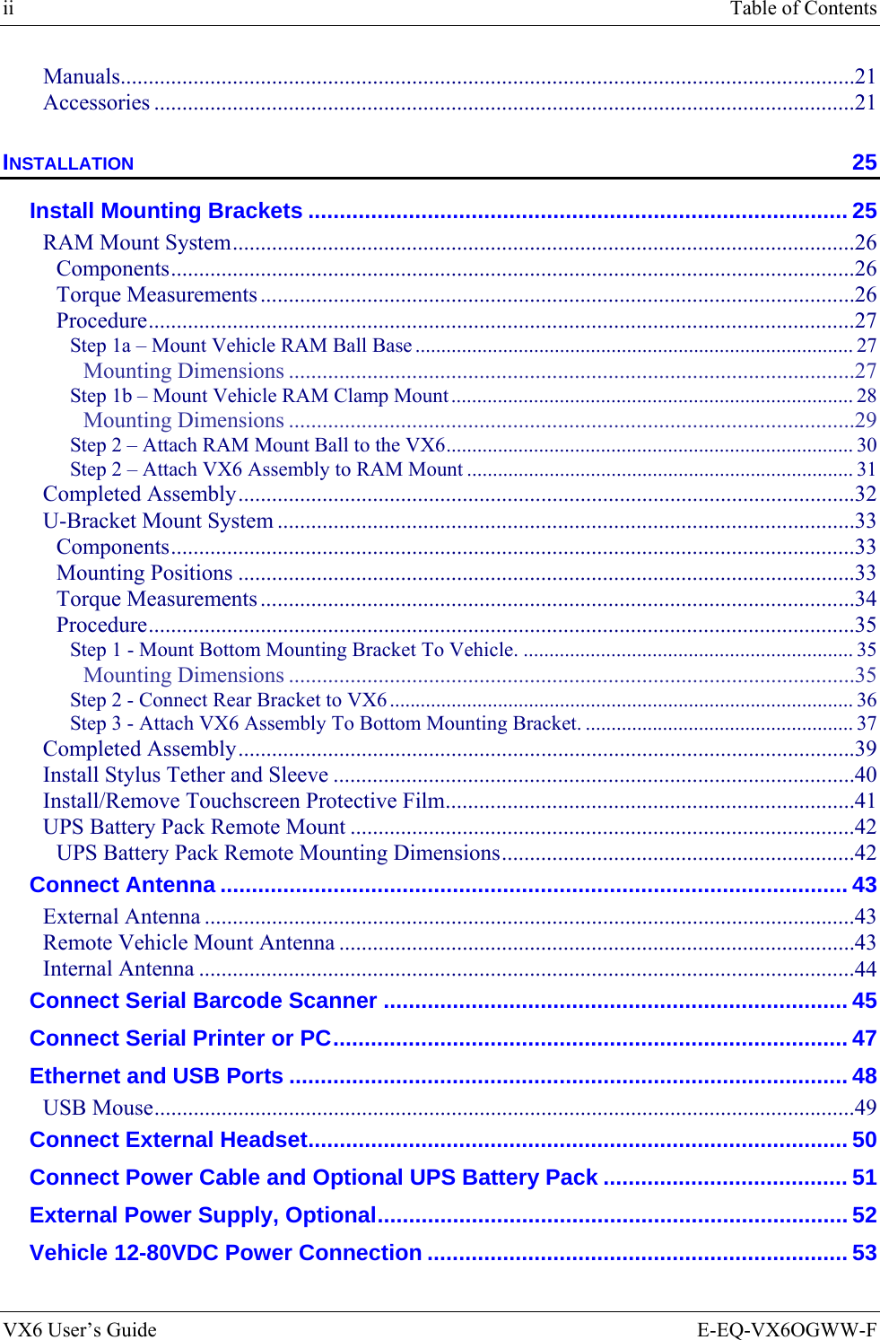
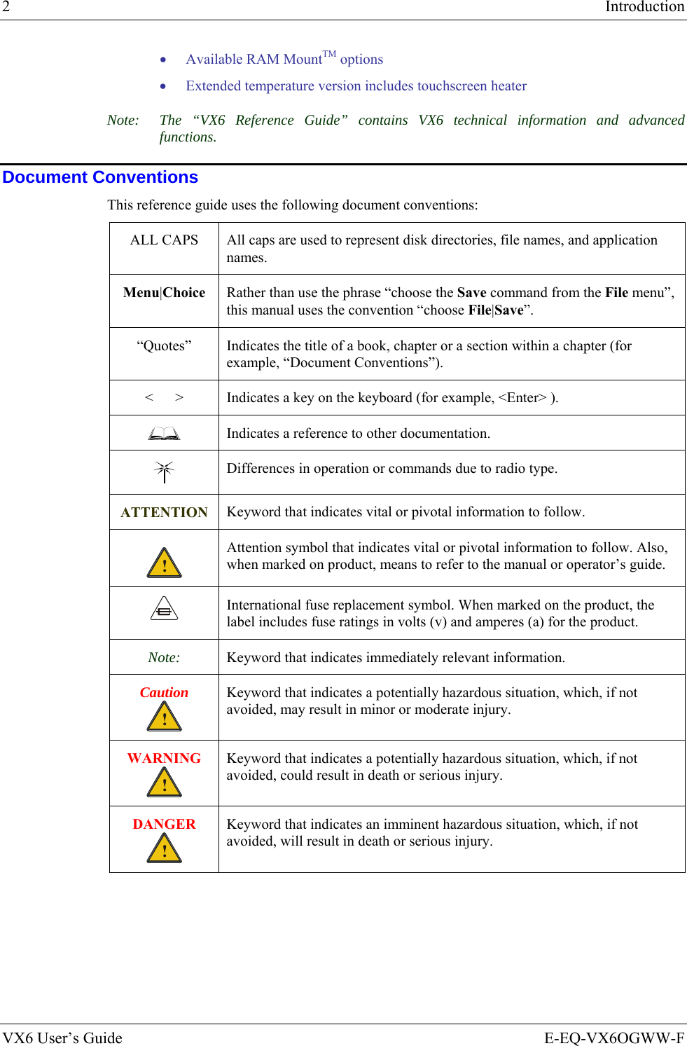
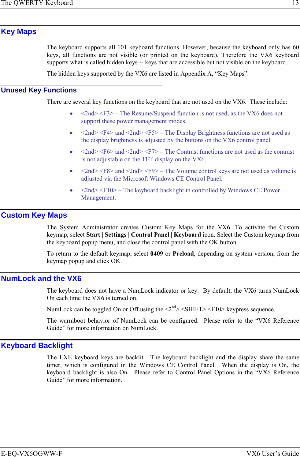
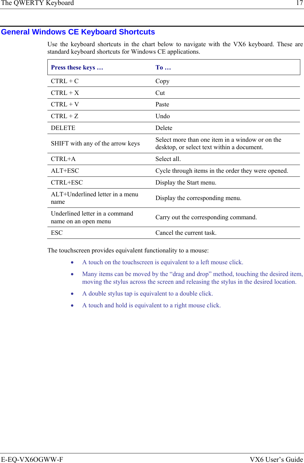
![Introduction 3 E-EQ-VX6OGWW-F VX6 User’s Guide Environmental Specifications Feature Specification Operating Temperature Standard version -4°F to 122°F (-20°C to 50°C) [non-condensing] Extended Temperature version -22º to 122º F (-30ºC to 50ºC [condensing] Storage Temperature Standard version -22°F to 140°F (-30°C to 60°C) [non-condensing] Extended Temperature version -22°F to 140°F (-30°C to 60°C) [condensing] Water, Sand Dust IP66 per IEC60529 Operating Humidity Standard version Up to 90% non-condensing at 104°F (40°C) Extended Temperature version 100% Vibration Based on MIL Std 810F ESD 15 kV Bluetooth Range 32.8 feet (10 meters) Direct line of sight only](https://usermanual.wiki/Honeywell/LXE4830P.User-Manual-VX6-part-1/User-Guide-886698-Page-13.png)
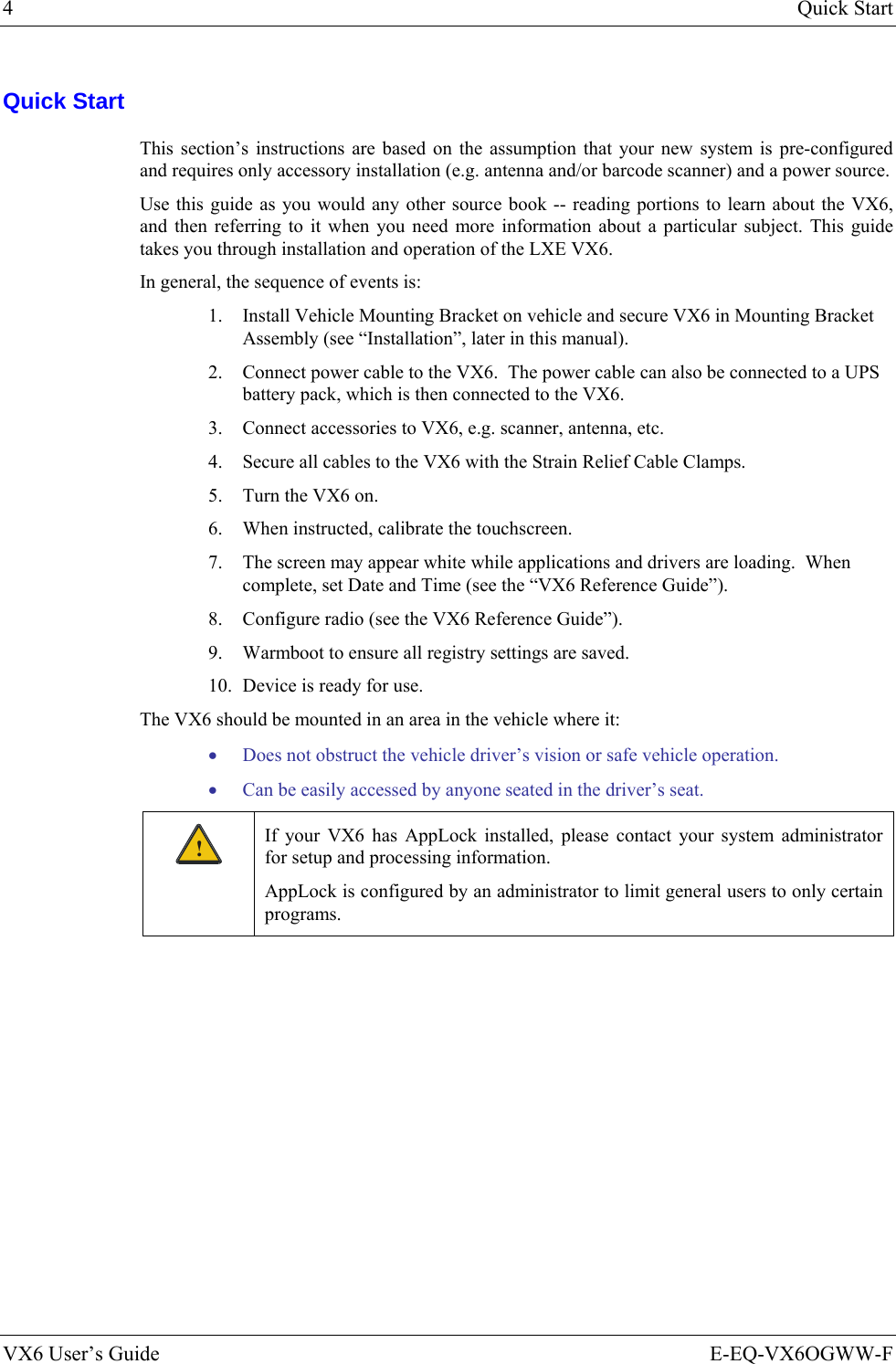
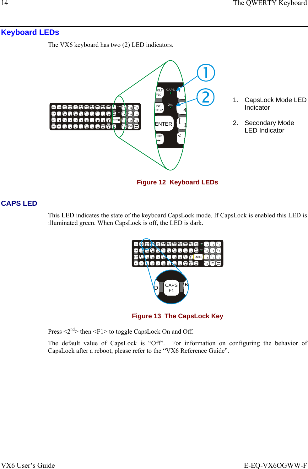
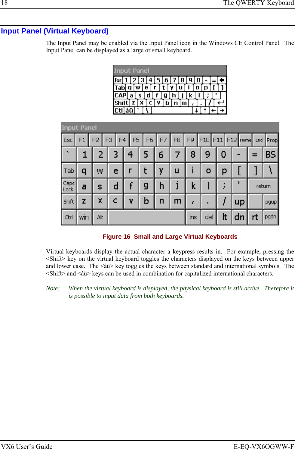
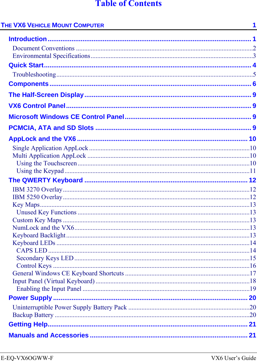
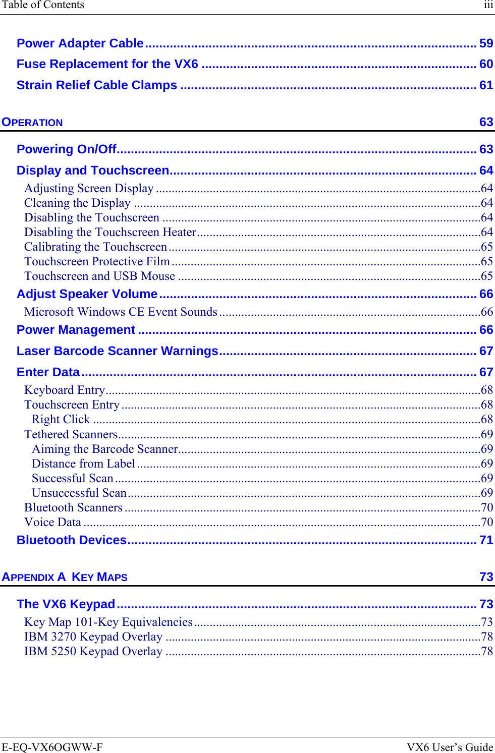
![12 The QWERTY Keyboard VX6 User’s Guide E-EQ-VX6OGWW-F The QWERTY Keyboard The VX6 has a QWERTY keyboard, available with a standard overlay, an IBM 3270 overlay or an IBM 5250 overlay. These keyboards have 101 keyboard functions, including a numeric keypad. Please refer to Appendix A, “Key Maps”, for keypress combinations. ESCSHIFT2NDALT SPF1 F2 F3 F4 F5 F6 F7 F8 F9CAPS BREAK R/SBCMNADFGHJKLSVXZ@#$% ^&*()F10BKLTINSBKSPEIOPRTUWYCTRL !|\ :; ‘,.?~_Home ENDENTERPgUpPgDn0.1245/78-+={}[]><DEL369CAPS2nd Figure 9 QWERTY Keyboard Standard IBM 3270 Overlay ESCSHIFT2NDALT SPF1 F2 F3 F4 F5 F6 F7 F8 F9CAPS BREAK R/SBCMNADFGHJKLSVXZ@#$%^&*()F10BKLTINSBKSPEIOPRTUWYCTRL !|\ :; ‘,.?~_Home ENDENTERPgUpPgDn0.1245/78-+={}[]><DEL369Attn SysReq DelClr NLIns E-InpCAPS2ndRstPA1 PA2 PA3 Figure 10 QWERTY Keyboard with IBM 3270 Overlay IBM 5250 Overlay ESCSHIFT2NDALT SPF1 F2 F3 F4 F5 F6 F7 F8 F9CAPS BREAK R/SBCMNADFGHJKLSVXZ@#$%^&*()F10BKLTINSBKSPEIOPRTUWYCTRL !|\ :; ‘,.?~_Home ENDENTERPgUpPgDn0.1245/78-+={}[]><DEL369Attn SysReq DelClrDupNLInsFld+Fld-E-InpField ExitCAPS2nd Figure 11 QWERTY Keyboard with IBM 5250 Overlay Note: Press the <CTRL> + <Enter> keys to initiate the IBM 5250 Field Exit Function.](https://usermanual.wiki/Honeywell/LXE4830P.User-Manual-VX6-part-1/User-Guide-886698-Page-22.png)