Honeywell LXE4830P 802.11g Compact Flash Module User Manual MX3X User s Guide
Honeywell International, Inc. 802.11g Compact Flash Module MX3X User s Guide
Contents
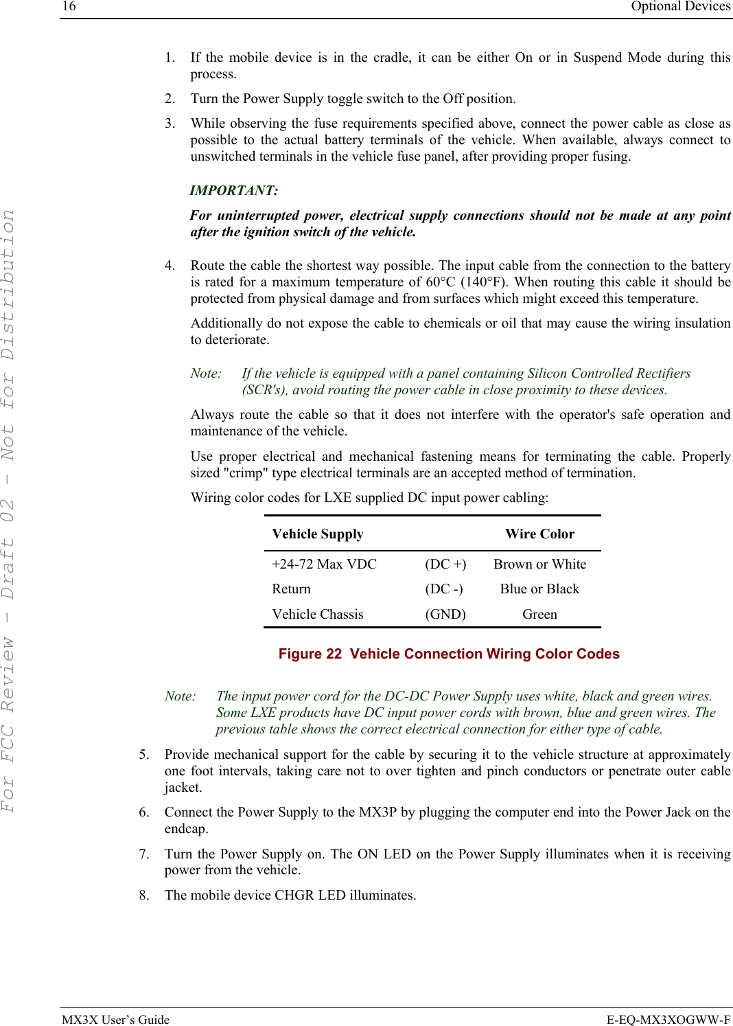
- 1. Manual HX1 rev3
- 2. Manual MX3X rev3
- 3. Manual MX5X rev3
- 4. Manual MX7 rev3
- 5. User Manual HX2
- 6. User Manual MX7
- 7. users manual
- 8. USERS MANUAL
- 9. User Manual MX3X
- 10. User Manual VX3X
- 11. User Manual VX6 part 1
- 12. User Manual VX6 part 2
- 13. User Manual VX7 part 1
- 14. User Manual VX7 part 2
- 15. Users Manual F300
- 16. Users Manual MX9
Manual MX3X rev3
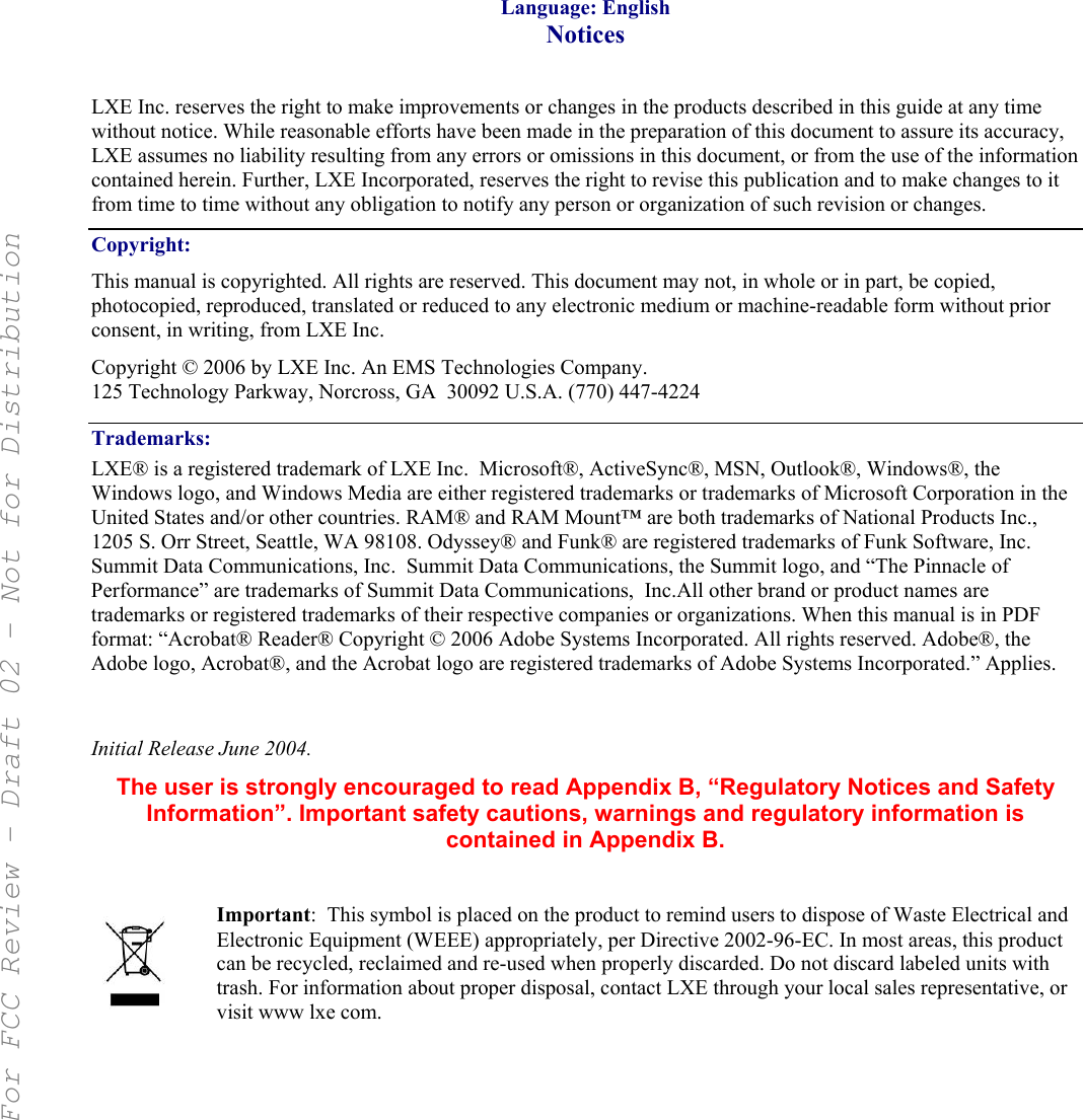

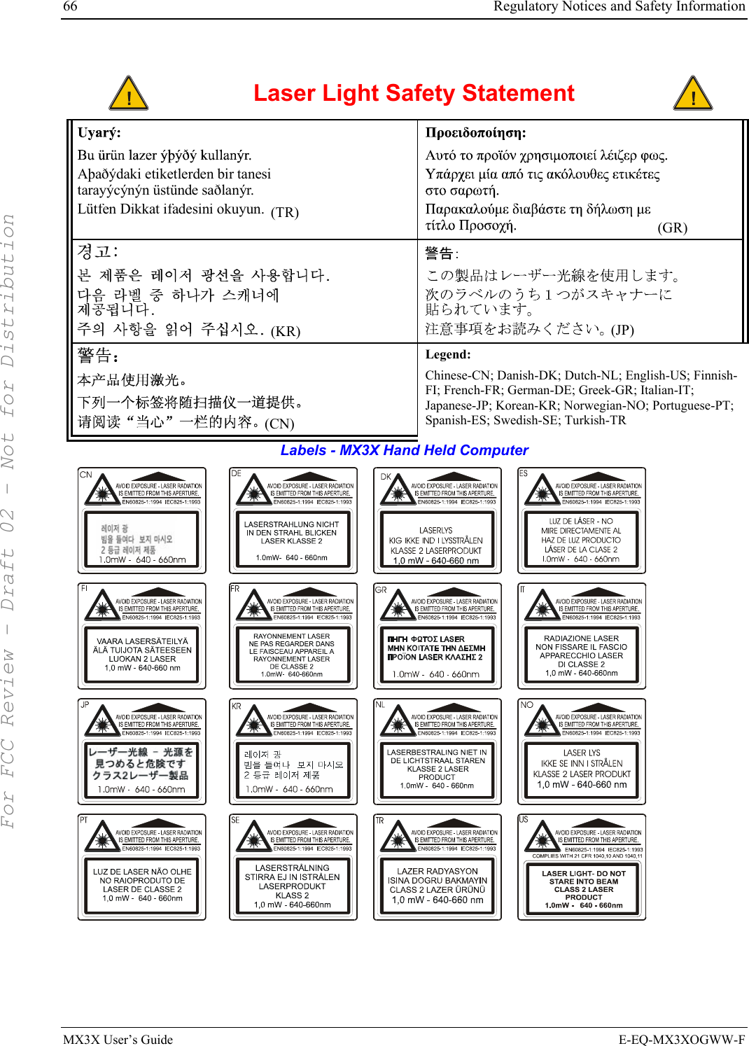
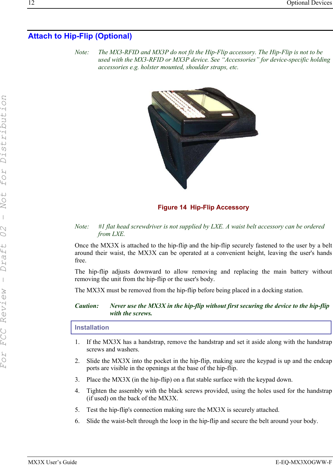
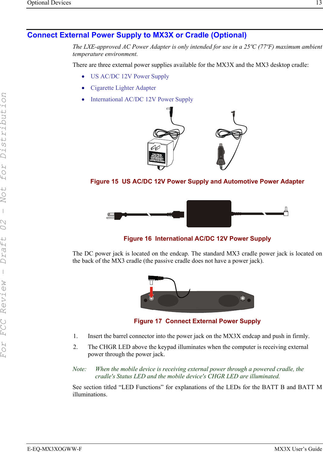
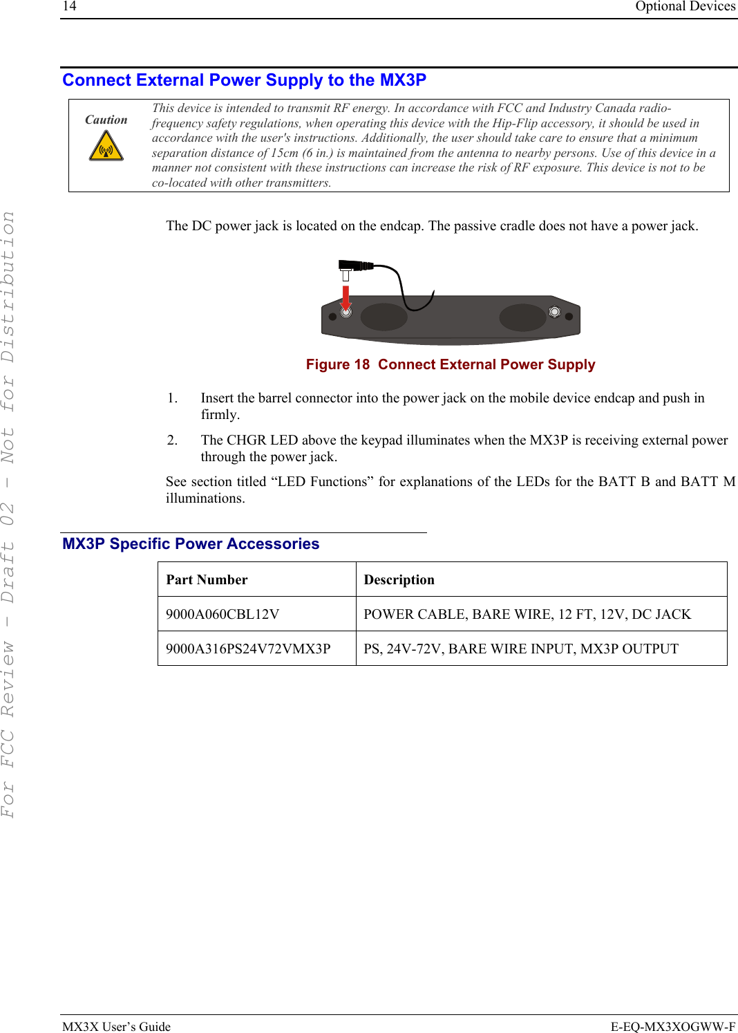
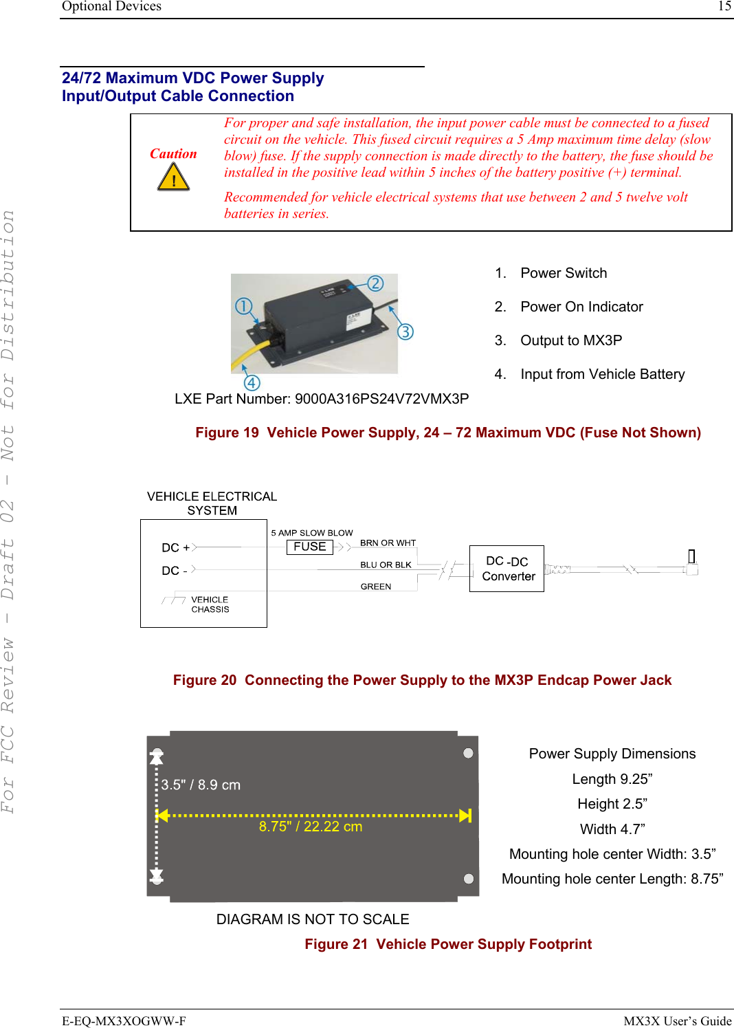
![Overview 3 E-EQ-MX3XOGWW-F MX3X User’s Guide Document Conventions ALL CAPS All caps are used to represent disk directories, file names, and application names. Menu | Choice Rather than use the phrase “choose the Save command from the File menu”, this guide uses the convention “choose File | Save”. “Quotes” Indicates the title of a book, chapter or a section within a chapter (for example, “Document Conventions”). < > Indicates a key on the keypad (for example, <Enter> ). Indicates a reference to other documentation. ATTENTION Keyword that indicates vital or pivotal information to follow. Attention symbol that indicates vital or pivotal information to follow. Also, when marked on product, means to refer to the user’s guide. International fuse replacement symbol. When marked on the product, the label includes fuse ratings in volts (v) and amperes (a) for the product. Note: Keyword that indicates immediately relevant information. CAUTION Keyword that indicates a potentially hazardous situation which, if not avoided, may result in minor or moderate injury. WARNING Keyword that indicates a potentially hazardous situation which, if not avoided, could result in death or serious injury. DANGER Keyword that indicates a imminent hazardous situation which, if not avoided, will result in death or serious injury. Environmental Specifications Operating Temperature Monochrome display : -4°F to 122°F (-20°C to 50°C) [non-condensing] Color display : 32°F to 122°F (0°C to 50°C) [non-condensing] Storage Temperature -22°F to 158°F (-30°C to 70°C) [non-condensing] Water and Dust MX3X : IEC IP66 MX3-RFID and MX3P : IEC IP65 Operating Humidity 5% to 95% non-condensing at 104°F (40°C) Vibration Based on MIL Std 810D ESD 8 kV air, 4kV contact Shock 75G, 5ms duration, 100 shock impacts Note: Environmental Specifications for the MX3 Cradles are contained in the “MX3 Cradle Reference Guide.” For FCC Review - Draft 02 - Not for Distribution](https://usermanual.wiki/Honeywell/LXE4830P.Manual-MX3X-rev3/User-Guide-696038-Page-11.png)
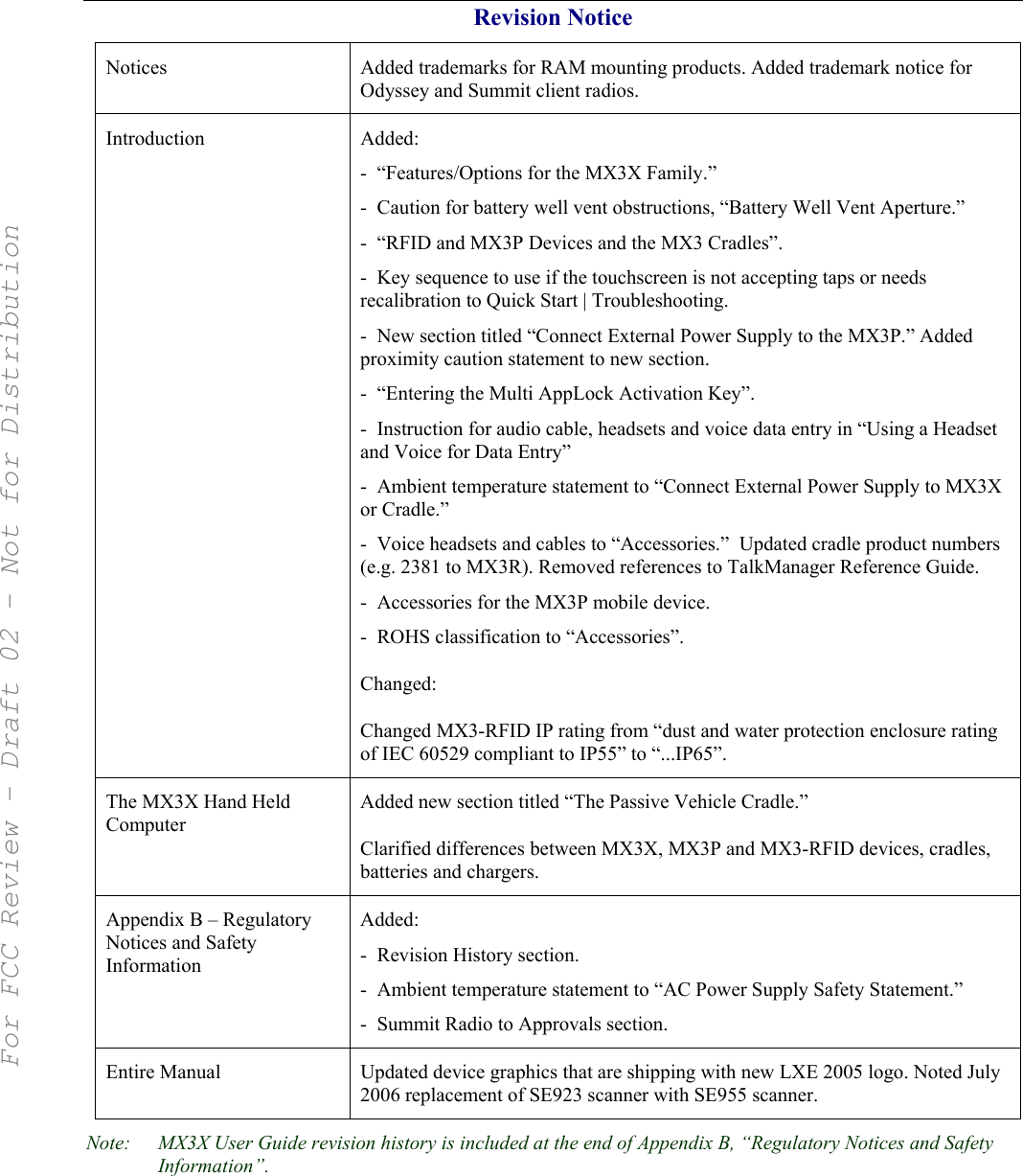
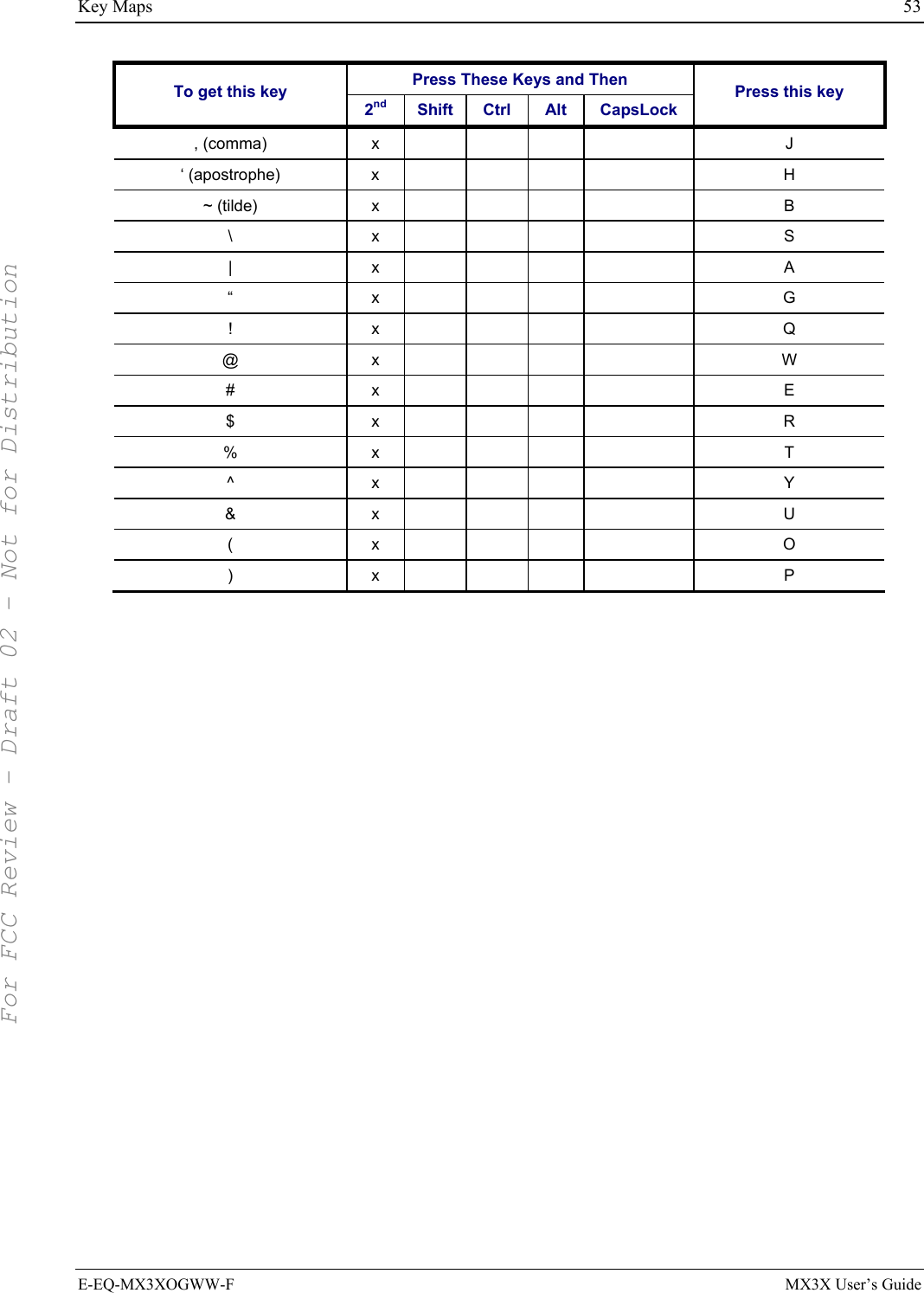
![52 Key Maps MX3X User’s Guide E-EQ-MX3XOGWW-F Press These Keys and Then To get this key 2nd Shift Ctrl Alt CapsLock Press this key S x S T x T U x U V x V W x W X x X Y x Y Z x Z 1 1 2 2 3 3 4 4 5 5 6 6 7 7 8 8 9 9 0 0 DOT DOT < x 0 [ x 1 ] x 2 > x 3 = x 4 { x 5 } x 6 / x 7 - x 8 + x 9 * x I : (colon) x D ; (semicolon) x F ? x L ` x N _ (underscore) x M For FCC Review - Draft 02 - Not for Distribution](https://usermanual.wiki/Honeywell/LXE4830P.Manual-MX3X-rev3/User-Guide-696038-Page-60.png)
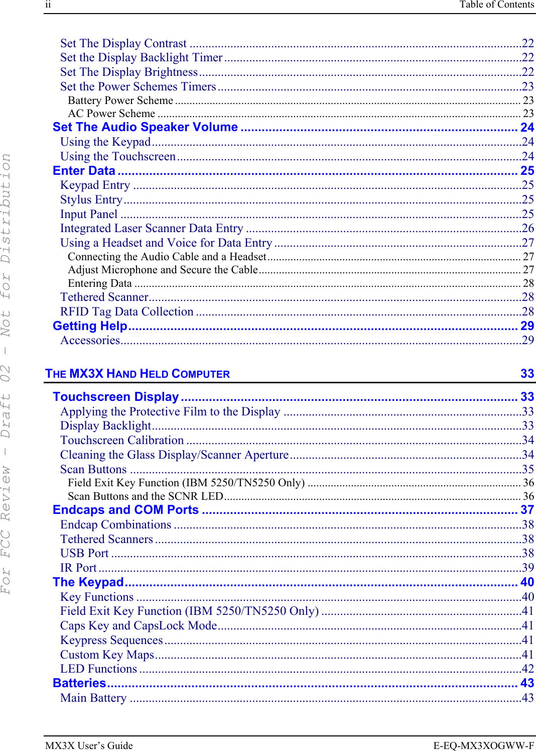
![Regulatory Notices and Safety Information 57 E-EQ-MX3XOGWW-F MX3X User’s Guide Approvals Product EMI / EMC Standards Safety Standards FCC Part 15 Subpart B, Class A EN 55022:1998 Class A EN 55024:1998 Industry Canada Class A MX3X MX3X with RFID Module MX3X with RFID Enclosure FCC Part 15.207 and 15.209, Class B ICES-0003 Class B AS/NZS 3548 Class B EN 301 489-1/17 CISPR22 and Class B UL 60950; CSA C22.2 No. 60950 CDRH: 21 CFR 1040.10 and 1040.11 EN 60950 IEC 60825-1 IEC 60950 Cradle Approvals: Product EMI / EMC Standards Safety Standards MX3 Table MX3 Vehicle Mount MX3-RFID / MX3P Passive Vehicle Cradle FCC Part 15 Subpart B, Class A EN 55022:1998 Class A EN 55024:1998 Industry Canada Class A UL 60950; CSA C22.2 No. 60950 EN 60950 IEC 60950 Transceiver: Transceiver RF Standards Notes 6726 (LXE Model No.) [Cisco] FCC Part 15, Subpart C FCC Part 2 EN 300 328 EN 300 826 IC-RSS 139 IC-RSS 102 Unlicensed Operation Unlicensed Operation Requires License for Outdoor Use 6816 (LXE Model No.) [Symbol] 2.4GHz Type II PCMCIA Card FCC Part 15, Subpart C FCC Part 2 EN 300 328 EN 300 826 IC-RSS 139 IC-RSS 102 Unlicensed Operation Unlicensed Operation Requires License for Outdoor Use 4830 (LXE Model No.) [LXE CF/Summit] 2.4GHz PCMCIA Card FCC Part 15.247, Subpart C FCC Bulletin OET-65 EN 300 328 IC-RSS 210 IC-RSS 102 Unlicensed Operation Unlicensed Operation Requires License for Outdoor Use For FCC Review - Draft 02 - Not for Distribution](https://usermanual.wiki/Honeywell/LXE4830P.Manual-MX3X-rev3/User-Guide-696038-Page-65.png)