Honeywell LXE4830P 802.11g COMPACT FLASH MODULE User Manual VX7 User s Guide
Honeywell International, Inc. 802.11g COMPACT FLASH MODULE VX7 User s Guide
Contents
- 1. Manual HX1 rev3
- 2. Manual MX3X rev3
- 3. Manual MX5X rev3
- 4. Manual MX7 rev3
- 5. User Manual HX2
- 6. User Manual MX7
- 7. users manual
- 8. USERS MANUAL
- 9. User Manual MX3X
- 10. User Manual VX3X
- 11. User Manual VX6 part 1
- 12. User Manual VX6 part 2
- 13. User Manual VX7 part 1
- 14. User Manual VX7 part 2
- 15. Users Manual F300
- 16. Users Manual MX9
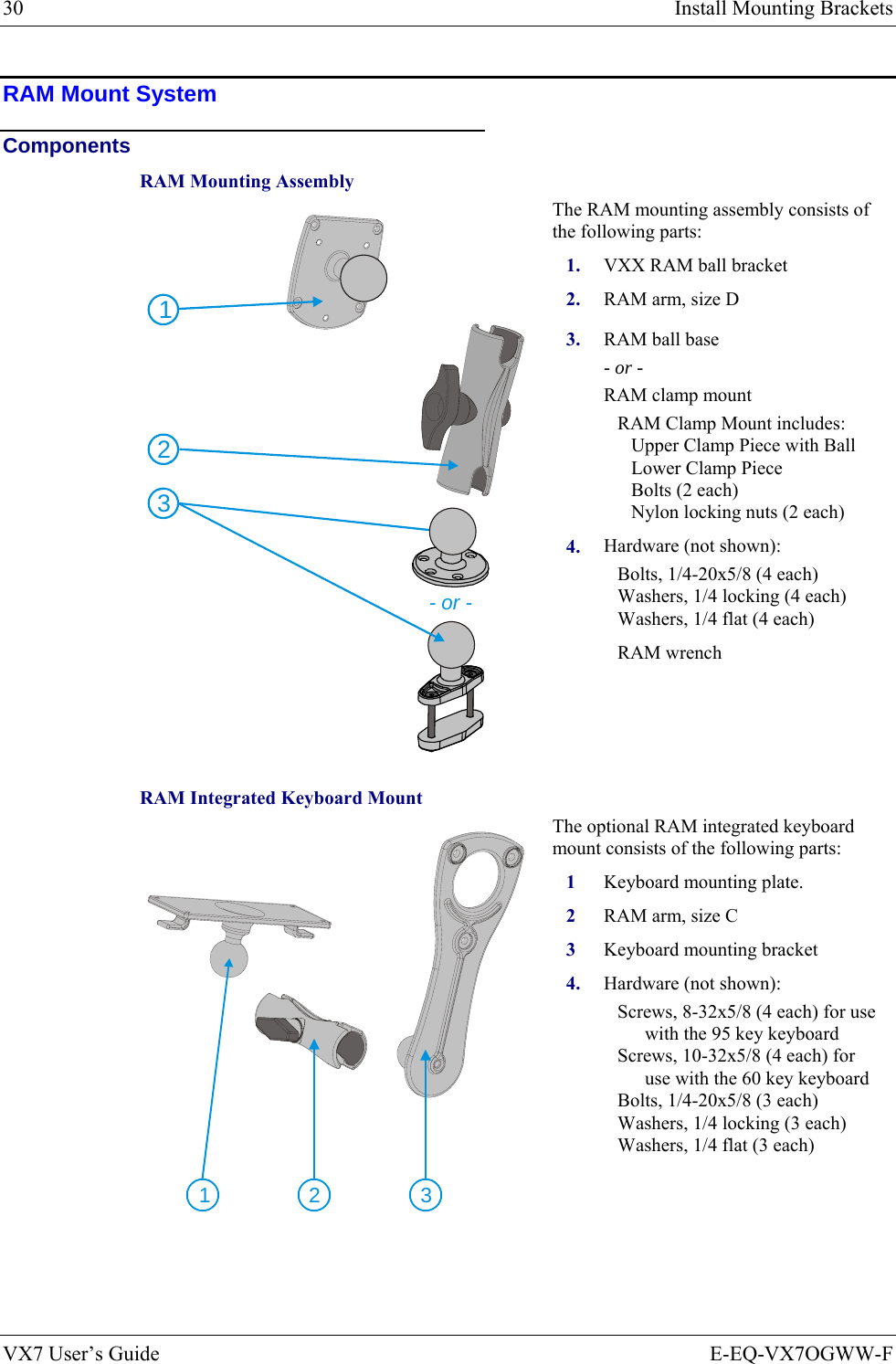
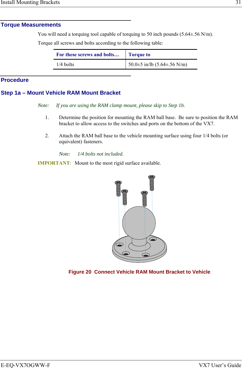
User Manual VX7 part 1
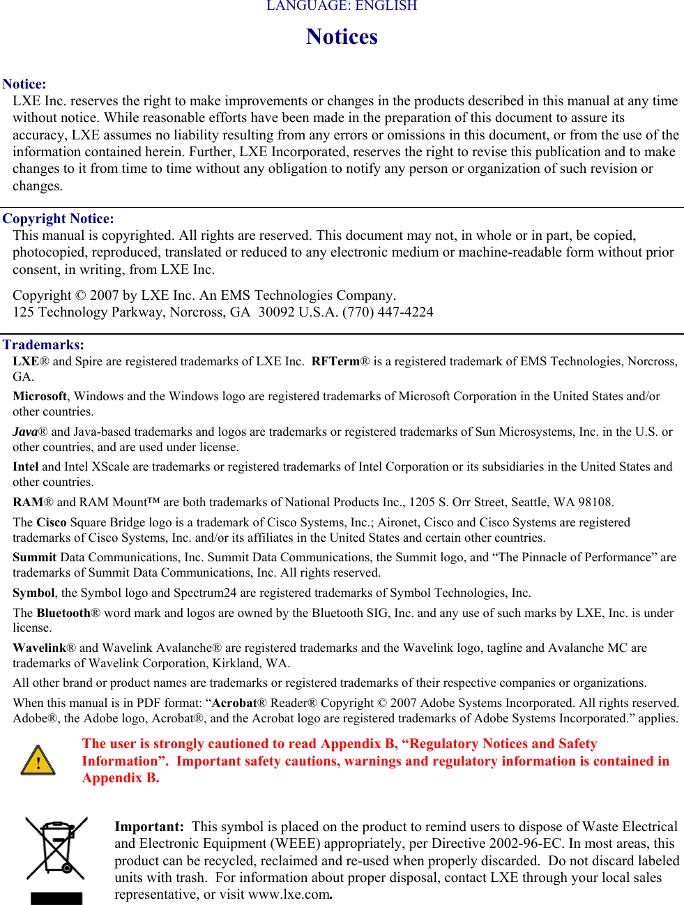

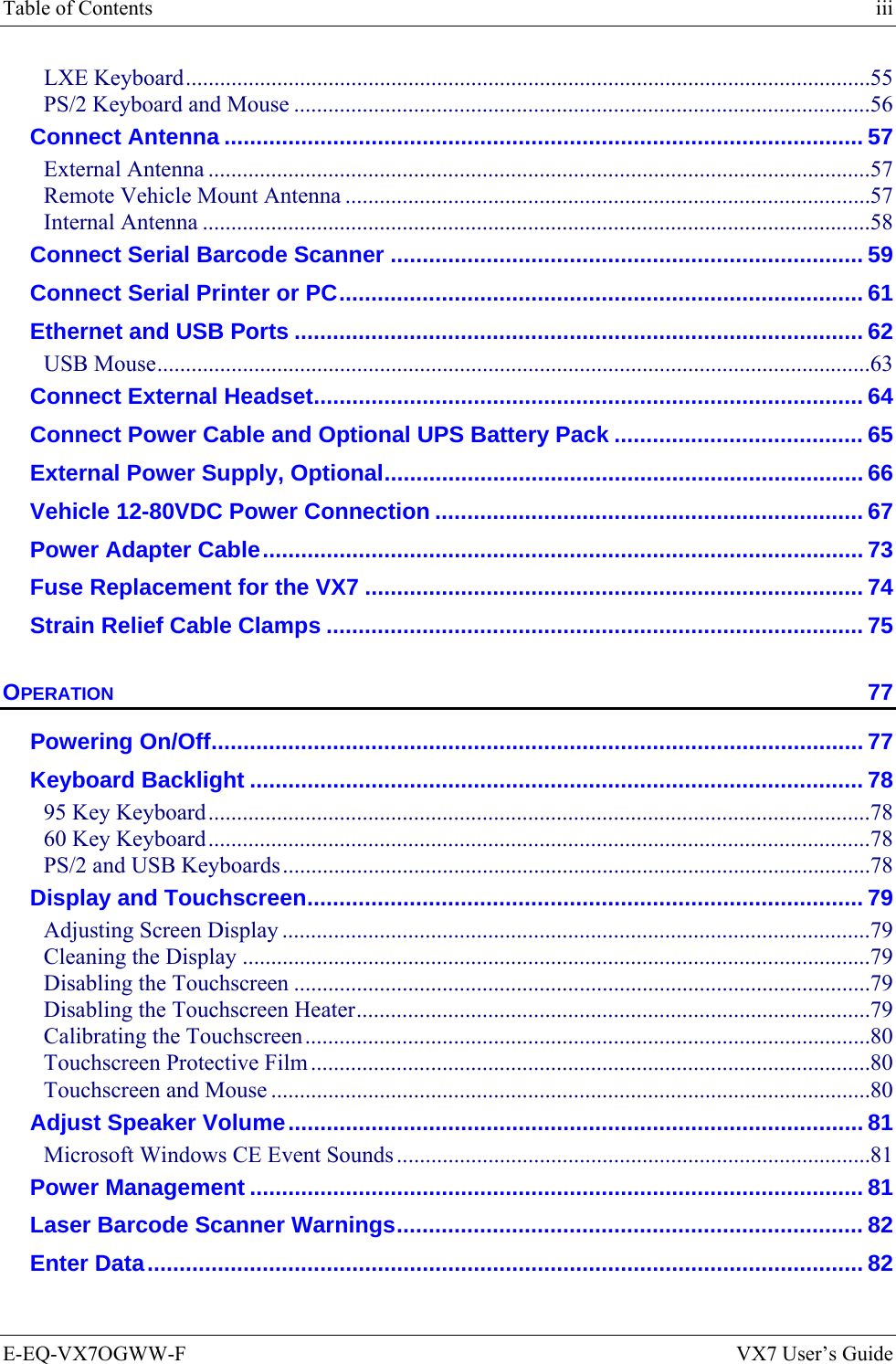
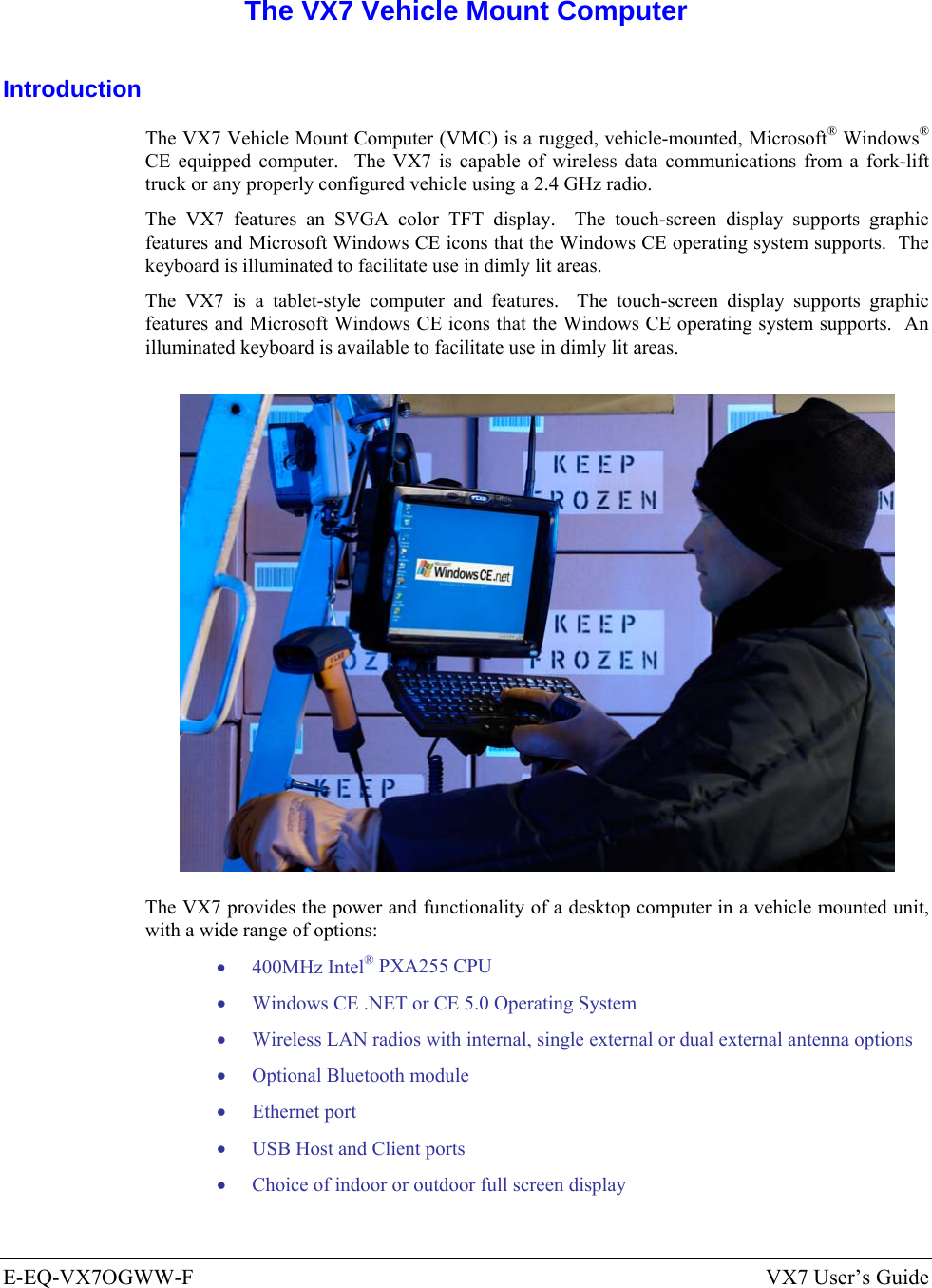
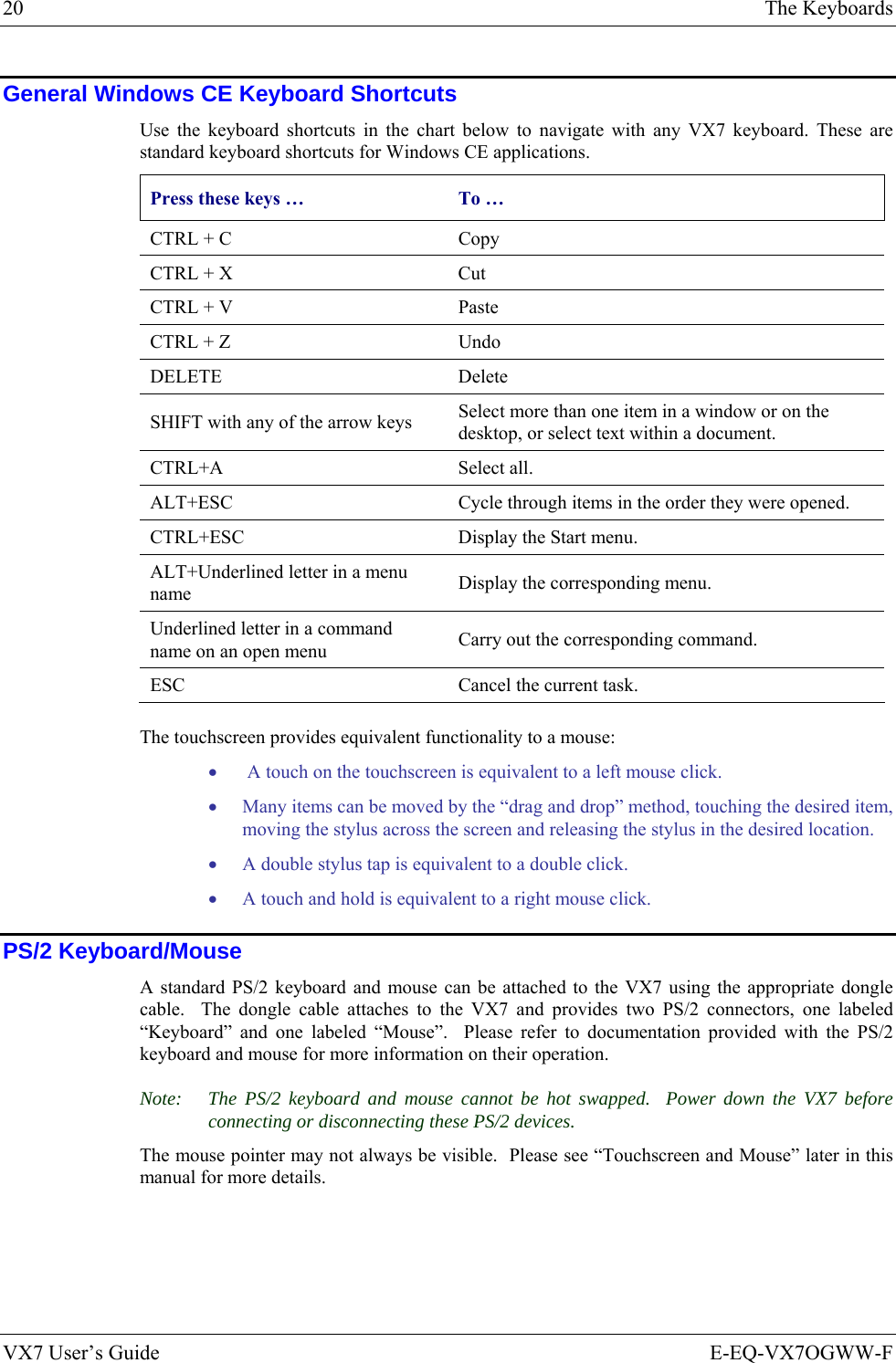
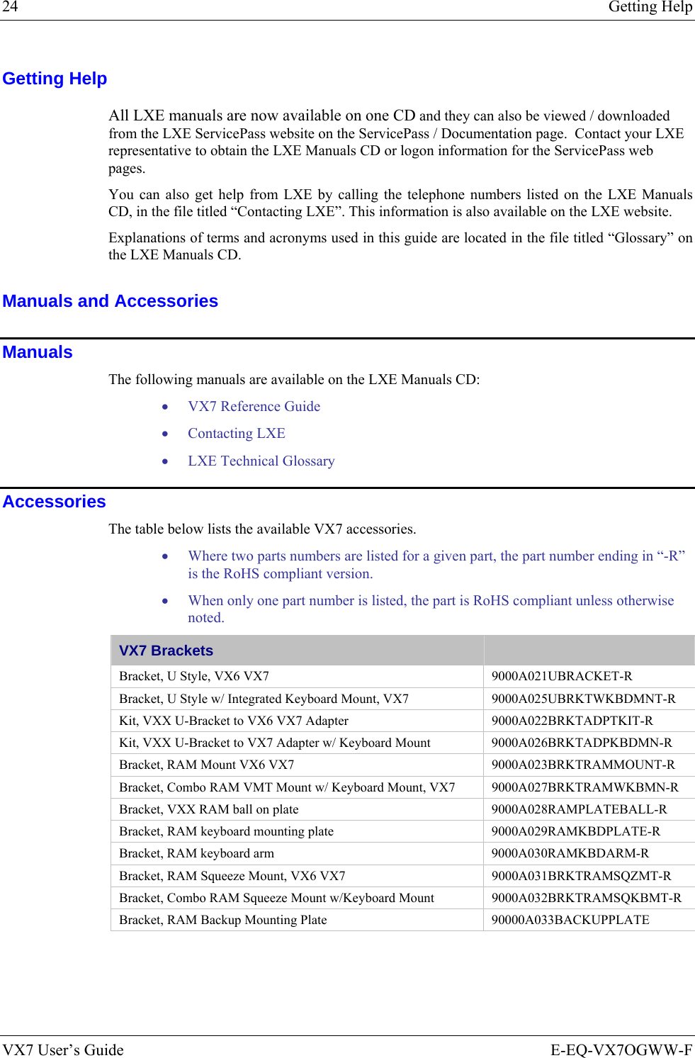
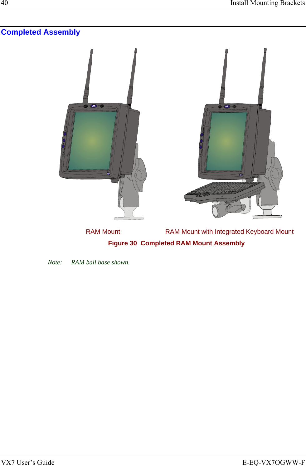
![Introduction 3 E-EQ-VX7OGWW-F VX7 User’s Guide Environmental Specifications Feature Specification Operating Temperature Standard version -4°F to 122°F (-20°C to 50°C) [non-condensing] Extended Temperature version -22º to 122º F (-30ºC to 50ºC [condensing] Storage Temperature Standard version -22°F to 140°F (-30°C to 60°C) [non-condensing] Extended Temperature version -22°F to 140°F (-30°C to 60°C) [condensing] Water, Sand Dust IP66 per IEC60529 Operating Humidity Standard version Up to 90% non-condensing at 104°F (40°C) Extended Temperature version 100% Vibration Based on MIL Std 810F ESD 15 kV Bluetooth Range 32.8 feet (10 meters) Direct line of sight only](https://usermanual.wiki/Honeywell/LXE4830P.User-Manual-VX7-part-1/User-Guide-886700-Page-13.png)
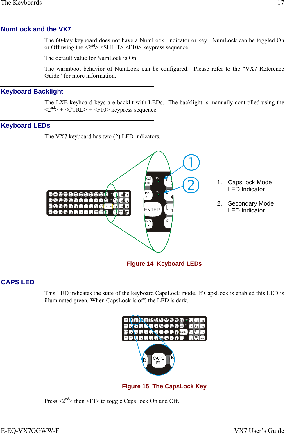
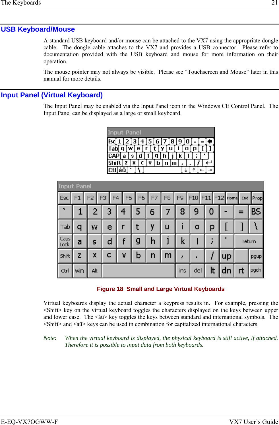
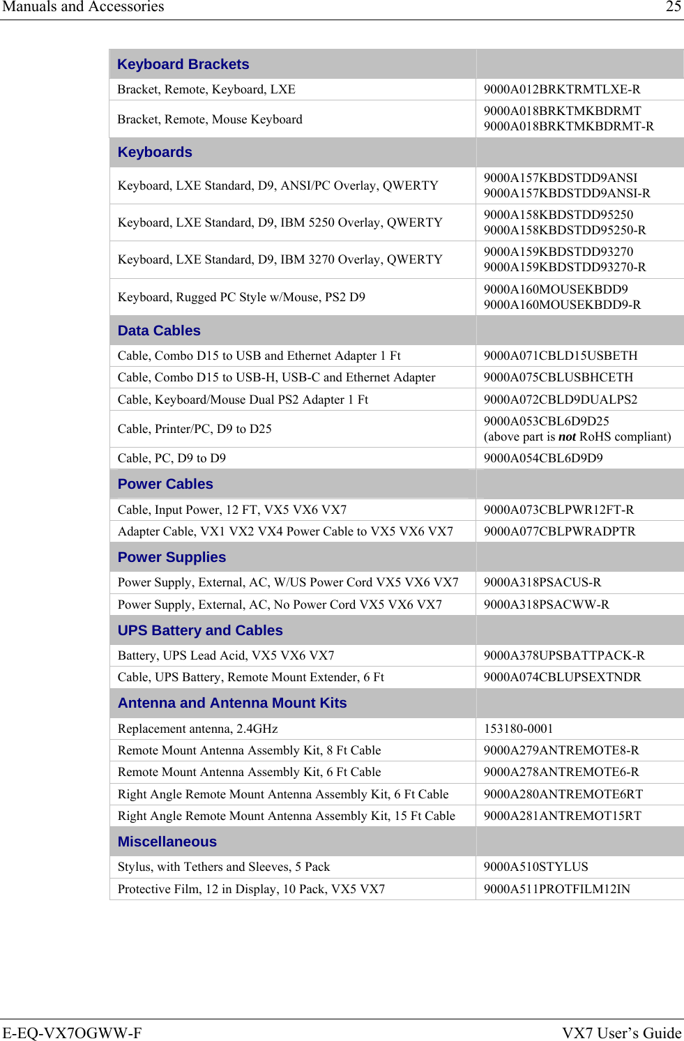
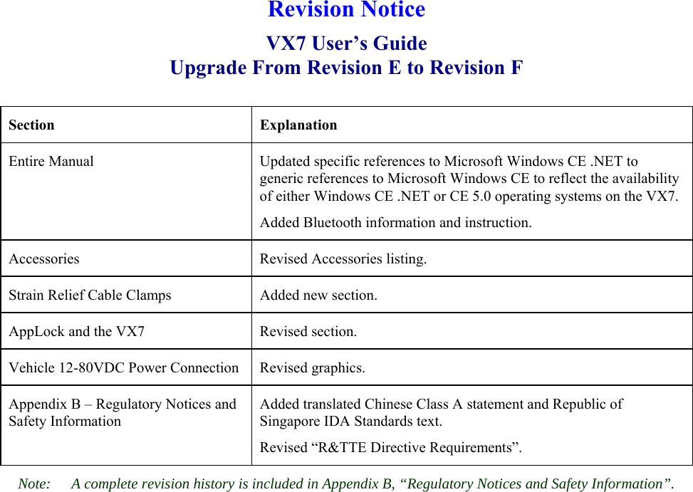
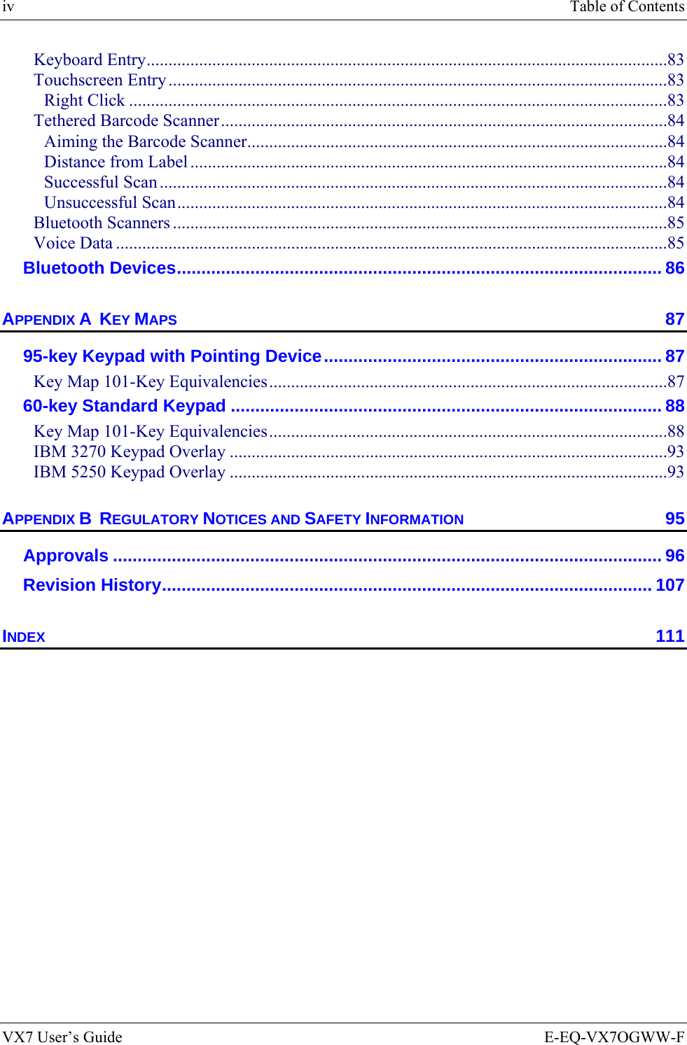
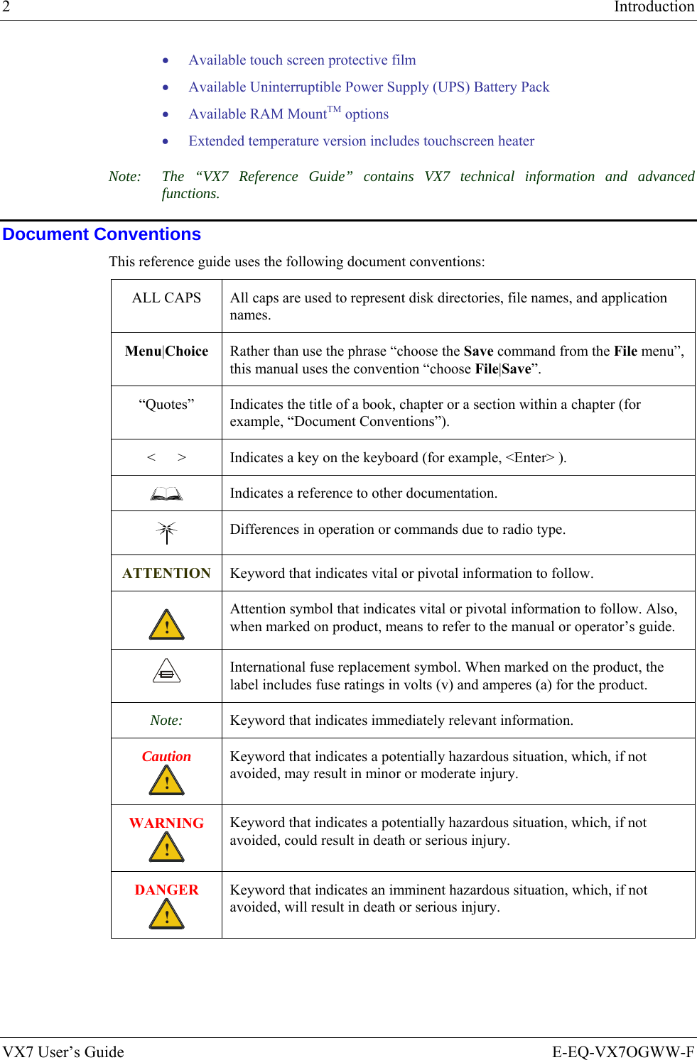
![12 The Keyboards VX7 User’s Guide E-EQ-VX7OGWW-F The Keyboards The following keyboard options are available for the VX7: • LXE 95-key QWERTY keyboard with integrated pointing device – a customized rugged keyboard connected to the VX7 via a watertight connector. • LXE 60-key QWERTY keyboard – a customized rugged keyboard connected to the VX7 via a watertight connector • A standard PS/2 keyboard via an adapter cable attached to the “Keyboard/MOUSE” port on the VX7. The adapter cable also provides a connector for a PS/2 mouse. • A USB keyboard via a dongle cable attached to the “Ethernet/USB” connector is available on certain VX7’s. Your system administrator can determine if your VX7 supports a USB keyboard. • A software keyboard, or virtual keyboard, can be displayed on the touch screen. The virtual keyboard can be used in place of, or in addition to, a physical keyboard. For more details on each keyboard type, please refer to the appropriate section later in this section. Esc F2 F3 F4 F5 F6 F7 F8 F9 F10 F11 F12PrintScreenSysRqScrollLock PauseBreakFn`1234567890-=BackSpaceNumLock/*-TabQWE R T Y U I OP[]\{}|7894561203Home PgUpCapsASDFGHJKL;':"EnterCtrl AltXCVBNM,./<>?ShiftAlt Ctrl InsEnd PgDn+~!@#$%^&*()_+LockShiftZLREnter.DelF1 95 key with Integrated Pointing Device 60 key Figure 9 The LXE Keyboards with Cable](https://usermanual.wiki/Honeywell/LXE4830P.User-Manual-VX7-part-1/User-Guide-886700-Page-22.png)
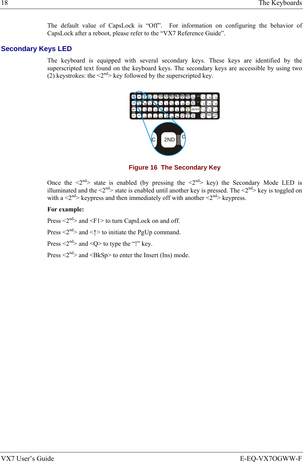
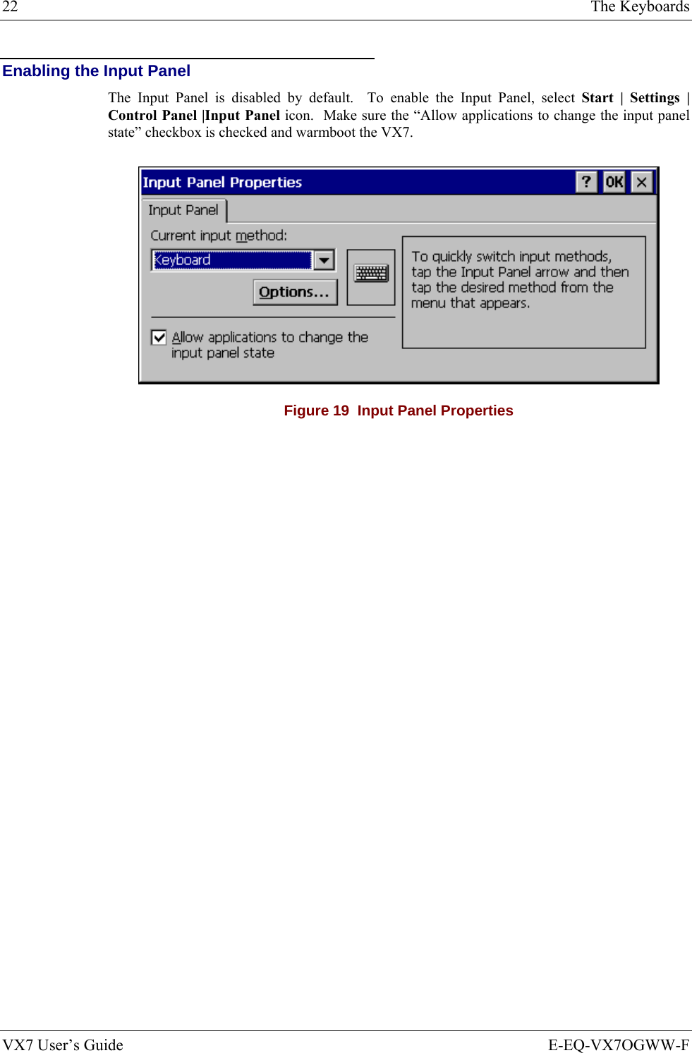
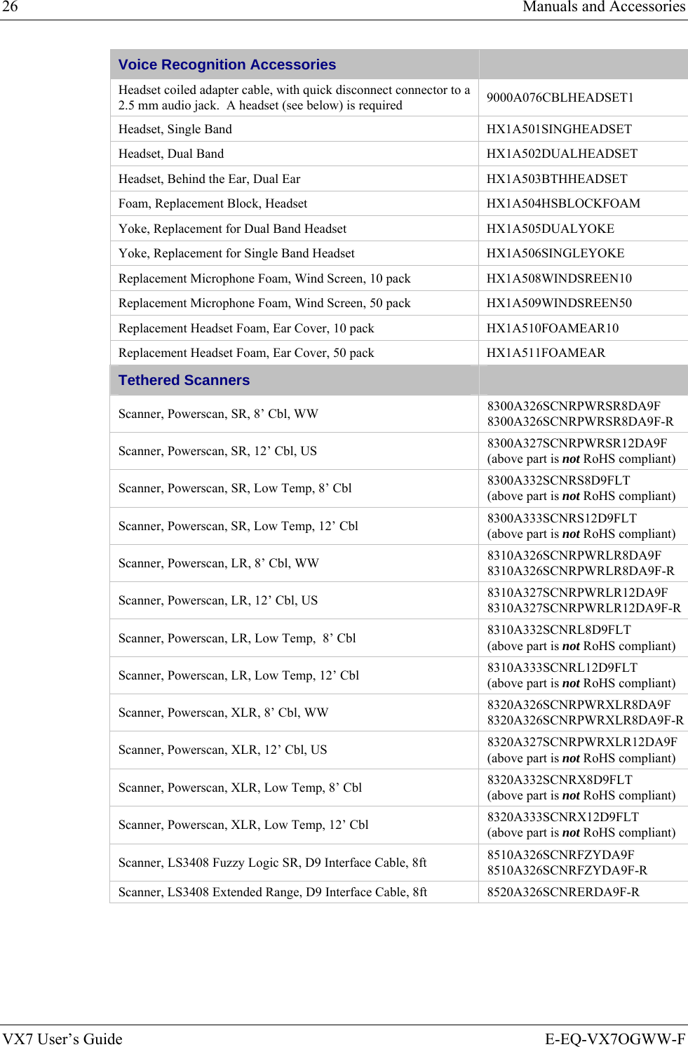
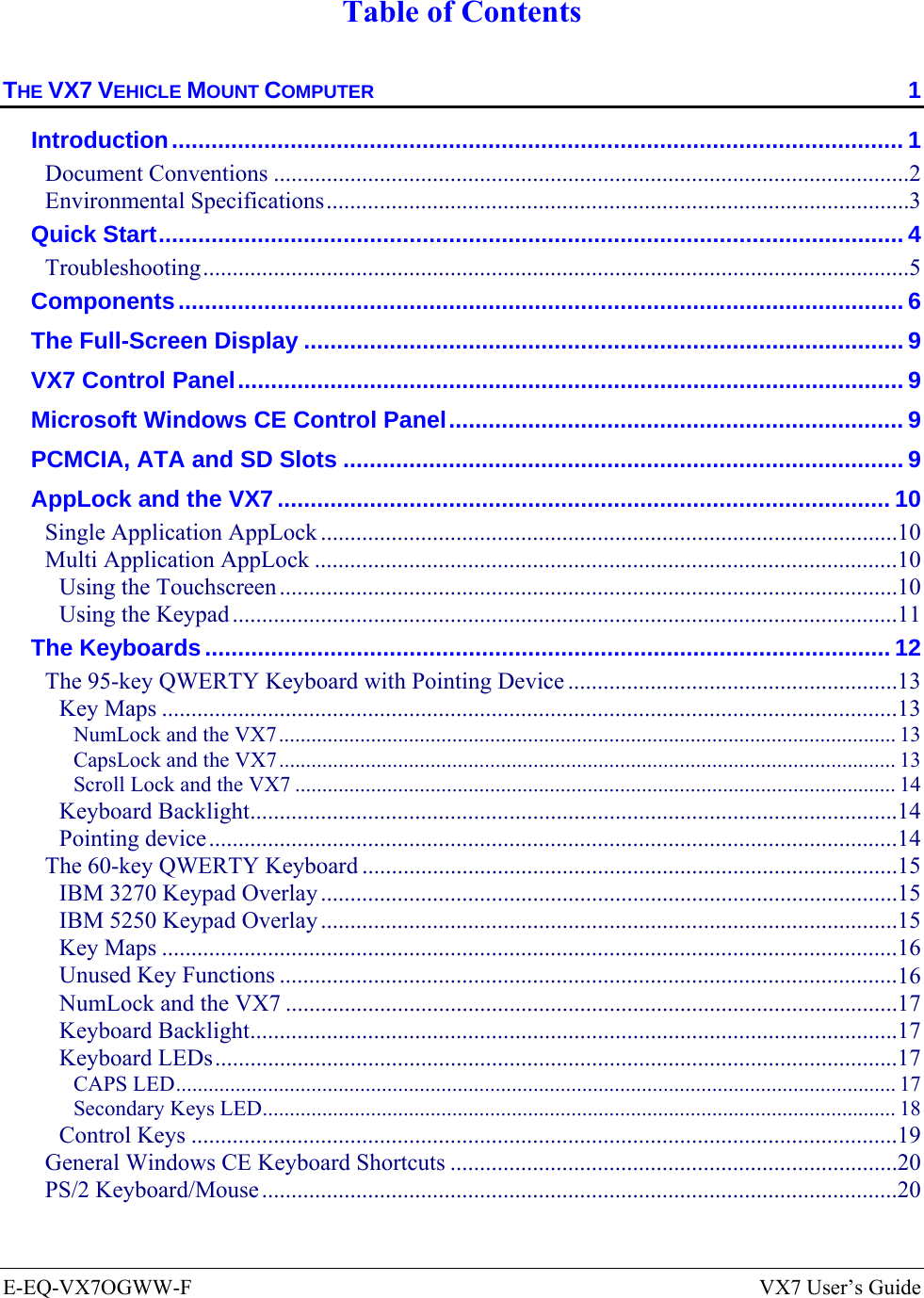
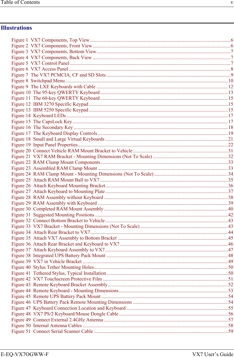
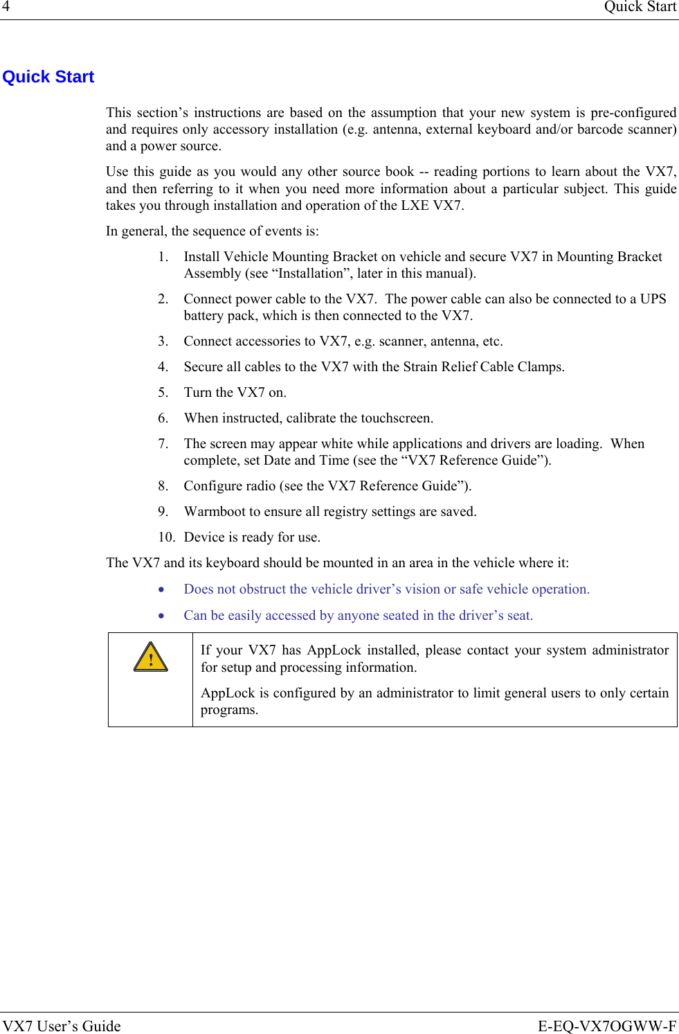
![The Keyboards 13 E-EQ-VX7OGWW-F VX7 User’s Guide The 95-key QWERTY Keyboard with Pointing Device Designed for ease of use with the Windows CE operating system, the 95-key keyboard with pointing device connects via a cable to the keyboard port on the VX7. Additional Windows keys (the Windows logo key and the Application key) and an integrated pointing device are provided for use with Windows CE operating system. Esc F2 F3 F4 F5 F6 F7 F8 F9 F10 F11 F12PrintScreenSysRq ScrollLock PauseBreakFn`1234567890-=BackSpaceNumLock/*-TabQWE R T Y U I OP[]\{}|7894561203Home PgUpCapsASDFGHJKL;':"EnterCtrl AltXCVBNM,./<>?ShiftAlt Ctrl InsEnd PgDn+~!@#$%^&*()_+LockShiftZLREnter.DelF1 Figure 10 The 95-key QWERTY Keyboard Note: The 2nd key function is available on the 60-key keyboard only. Key Maps The 95-key keyboard supports all 104 keyboard functions (101 keyboard standard plus Windows keys) and includes an integrated pointing device and left and right mouse buttons. However, because the keyboard only has 95 keys, all functions are not visible (or printed on the keyboard). Therefore the VX7 keyboard supports what is called hidden keys -- keys that are accessible but not visible on the keyboard. The hidden keys supported by the VX7 are listed in Appendix A, “Key Maps”. NumLock and the VX7 For the 95-key keyboard, the NumLock key and the numeric keys are backlit green when NumLock is off. When NumLock is on, the backlight for the NumLock key and the numeric keys is amber. The default value for NumLock is On. The warmboot behavior of NumLock can be configured. Please refer to the “VX7 Reference Guide” for more information. CapsLock and the VX7 For the 95-key keyboard, the CapsLock key is backlit green when CapsLock is off. When CapsLock is on, the backlight for the CapsLock key is amber. The default value for CapsLock is On. The warmboot behavior of CapsLock can be configured. Please refer to the “VX7 Reference Guide” for more information.](https://usermanual.wiki/Honeywell/LXE4830P.User-Manual-VX7-part-1/User-Guide-886700-Page-23.png)
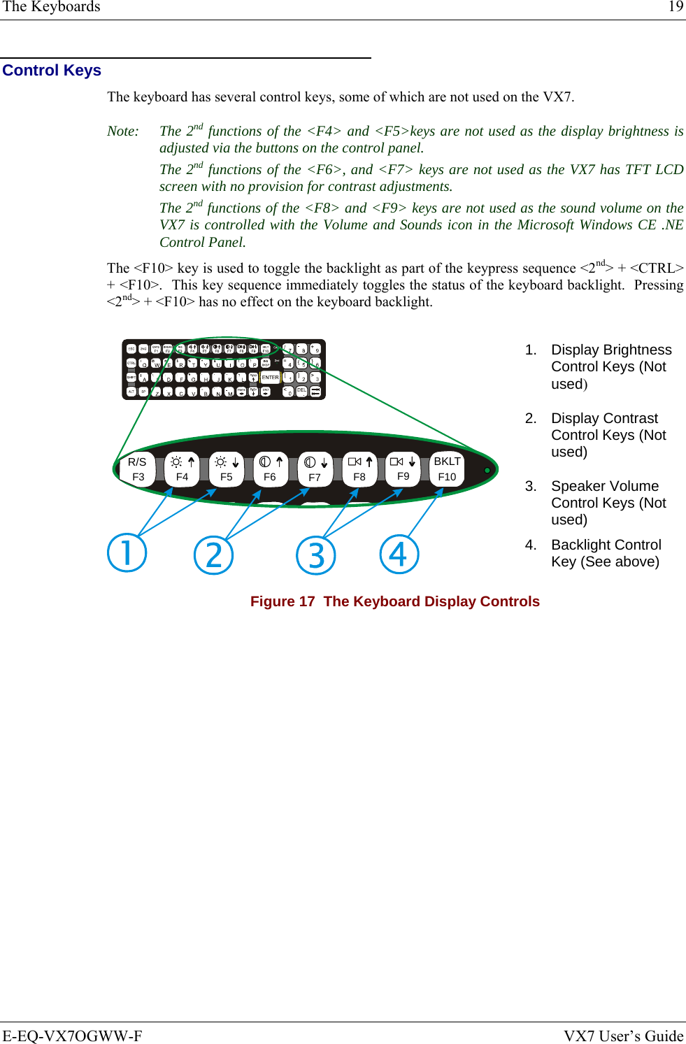
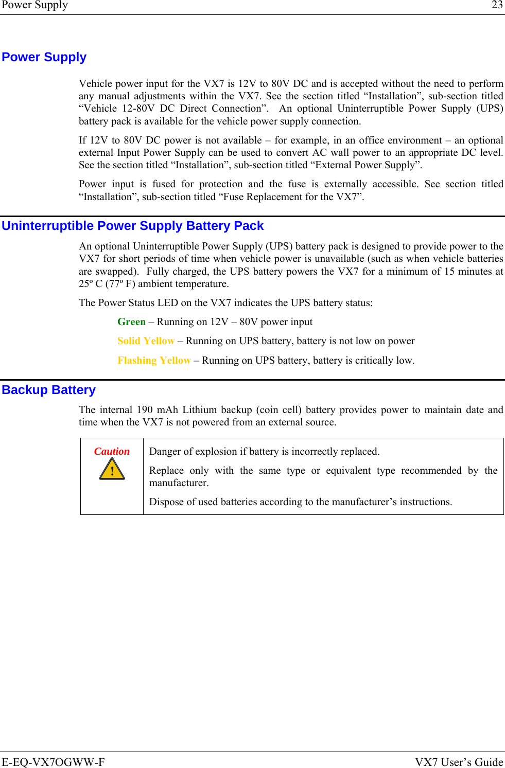
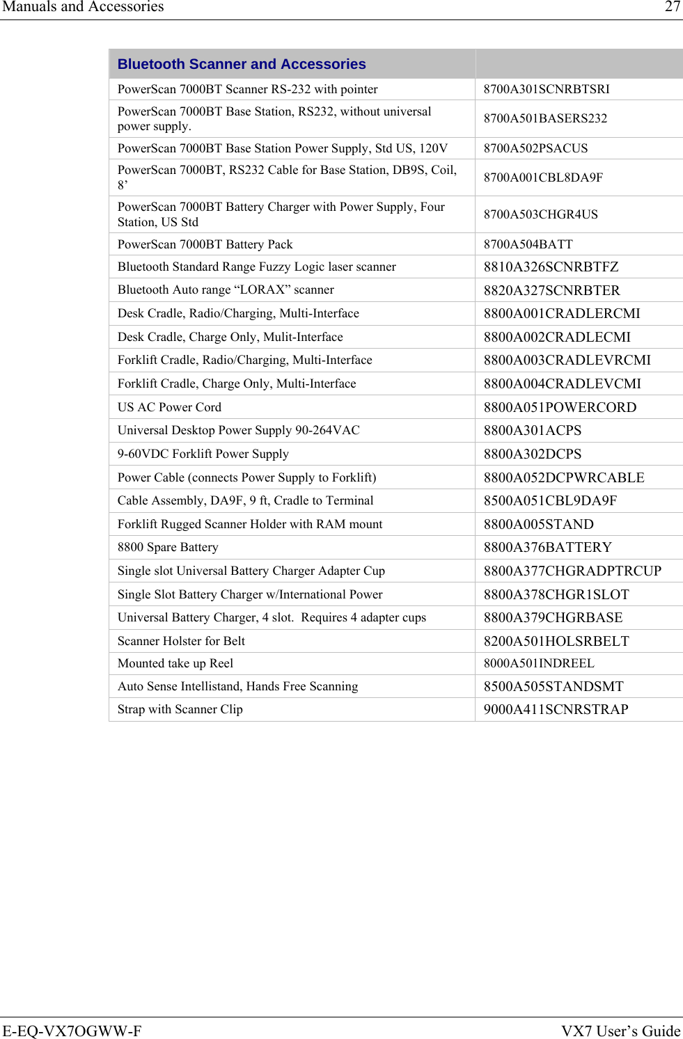
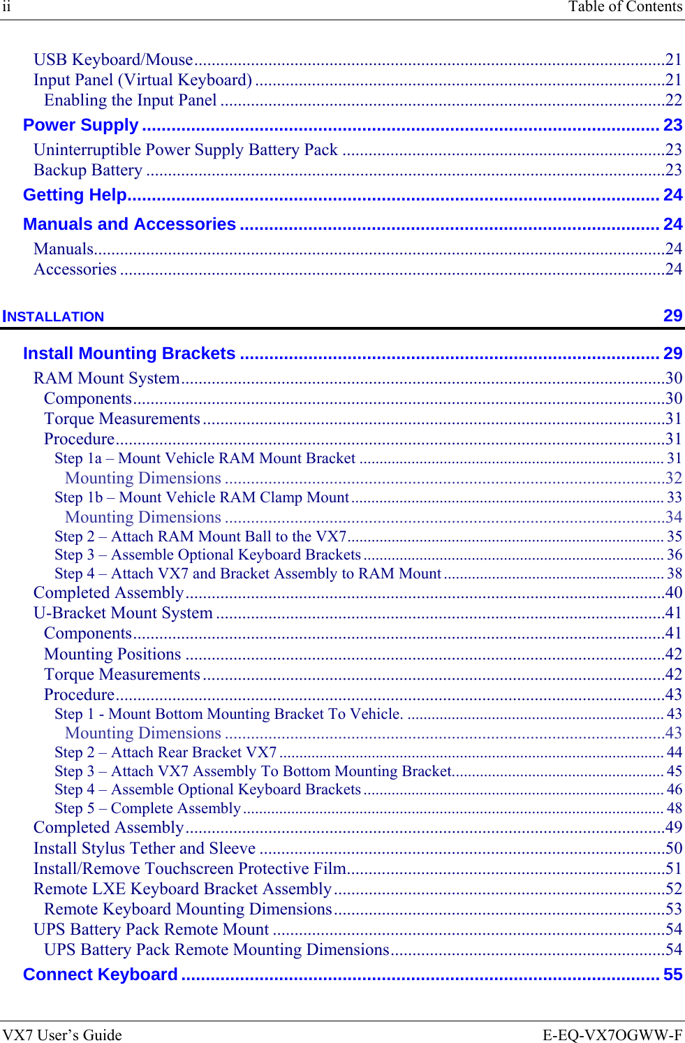
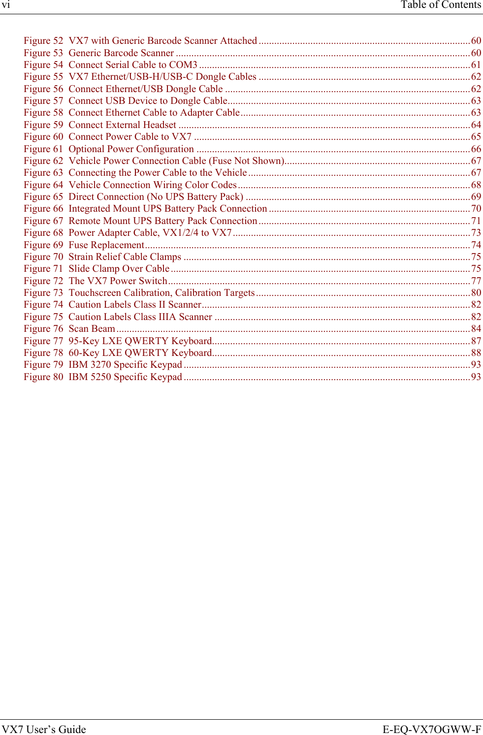
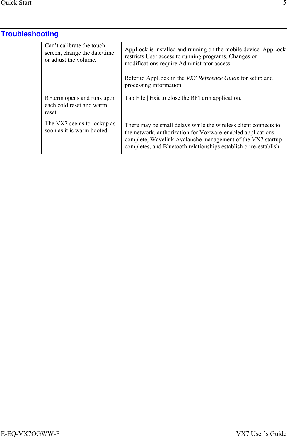
![The Keyboards 15 E-EQ-VX7OGWW-F VX7 User’s Guide The 60-key QWERTY Keyboard The 60-key keyboard has 101 keyboard functions, including a numeric keyboard pad. Please refer to Appendix A, “Key Maps”, for keypress combinations. ESCSHIFT2NDALT SPF1 F2 F3 F4 F5 F6 F7 F8 F9CAPS BREAK R/SBCMNADFGHJKLSVXZ@#$% ^&*()F10BKLTINSBKSPEIOPRTUWYCTRL !|\ :; ‘,.?~_Home ENDENTERPgUpPgDn0.1245/78-+={}[]><DEL369CAPS2nd Figure 11 The 60-key QWERTY Keyboard IBM 3270 Keypad Overlay ESCSHIFT2NDALT SPF1 F2 F3 F4 F5 F6 F7 F8 F9CAPS BREAK R/SBCMNADFGHJKLSVXZ@#$%^&*()F10BKLTINSBKSPEIOPRTUWYCTRL !|\ :; ‘,.?~_Home ENDENTERPgUpPgDn0.1245/78-+={}[]><DEL369Attn SysReq DelClr NLIns E-InpCAPS2ndRstPA1 PA2 PA3 Figure 12 IBM 3270 Specific Keypad The 60-key keypad is available with an IBM 3270 overlay designed to allow the user to enter terminal emulator commands when running LXE’s RFTerm™ program. IBM 5250 Keypad Overlay ESCSHIFT2NDALT SPF1 F2 F3 F4 F5 F6 F7 F8 F9CAPS BREAK R/SBCMNADFGHJKLSVXZ@#$%^&*()F10BKLTINSBKSPEIOPRTUWYCTRL !|\ :; ‘,.?~_Home ENDENTERPgUpPgDn0.1245/78-+={}[]><DEL369Attn SysReq DelClrDupNLInsFld+Fld-E-InpField ExitCAPS2nd Figure 13 IBM 5250 Specific Keypad The 60-key keypad is available with an IBM 5250 overlay designed to allow the user to enter terminal emulator commands when running LXE’s RFTerm™ program.](https://usermanual.wiki/Honeywell/LXE4830P.User-Manual-VX7-part-1/User-Guide-886700-Page-25.png)