Honeywell LXE4830P 802.11g COMPACT FLASH MODULE User Manual VX7 User s Guide
Honeywell International, Inc. 802.11g COMPACT FLASH MODULE VX7 User s Guide
Contents
- 1. Manual HX1 rev3
- 2. Manual MX3X rev3
- 3. Manual MX5X rev3
- 4. Manual MX7 rev3
- 5. User Manual HX2
- 6. User Manual MX7
- 7. users manual
- 8. USERS MANUAL
- 9. User Manual MX3X
- 10. User Manual VX3X
- 11. User Manual VX6 part 1
- 12. User Manual VX6 part 2
- 13. User Manual VX7 part 1
- 14. User Manual VX7 part 2
- 15. Users Manual F300
- 16. Users Manual MX9
User Manual VX7 part 2
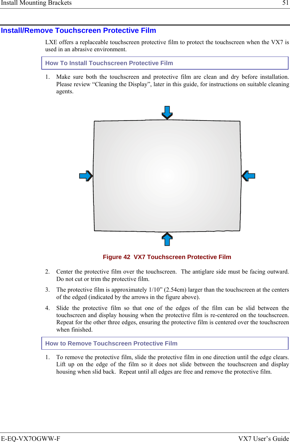
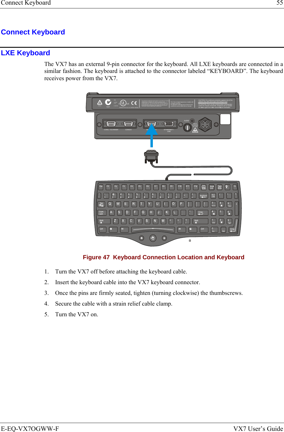
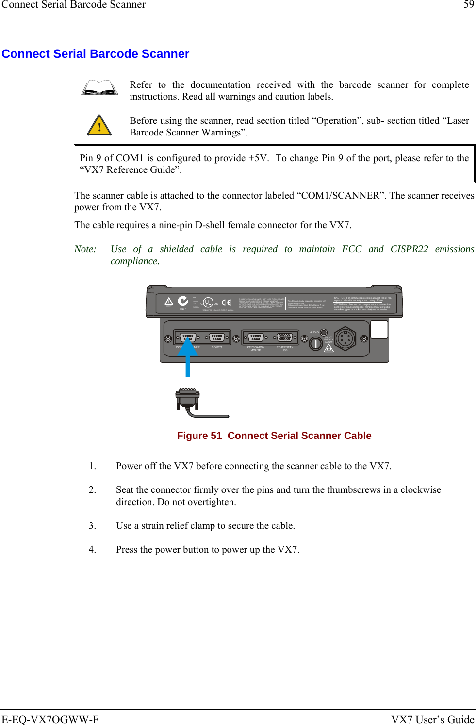
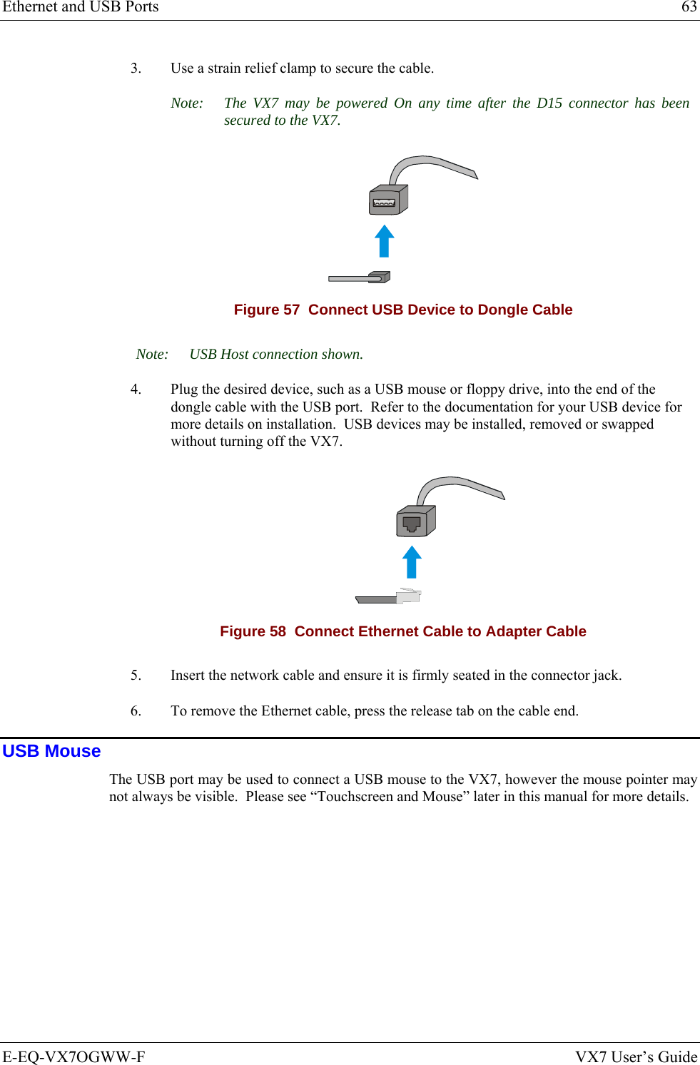
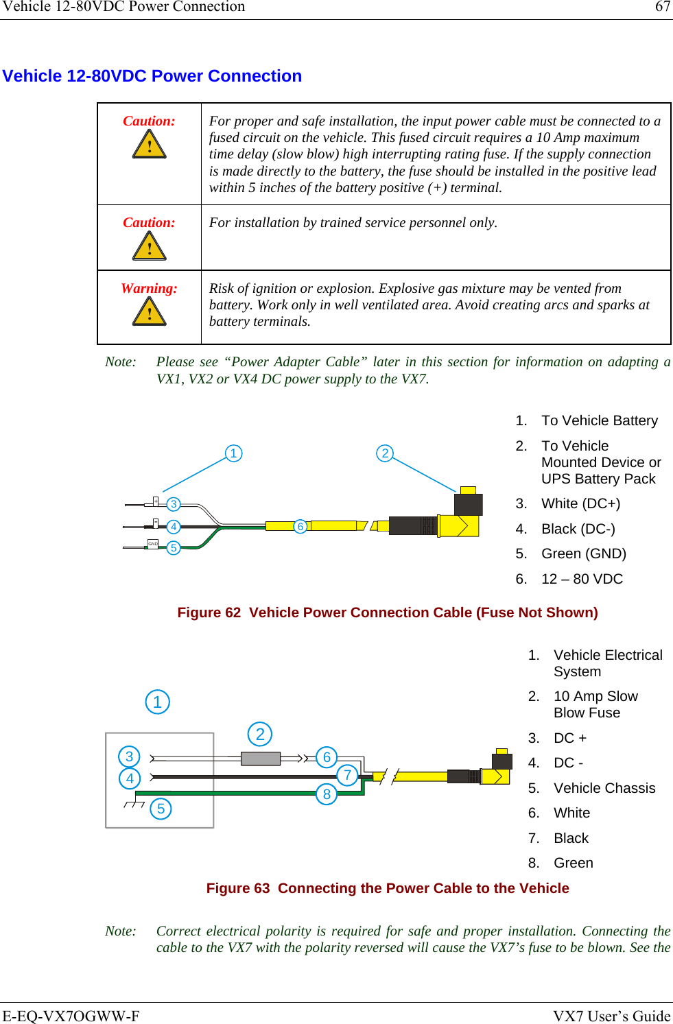

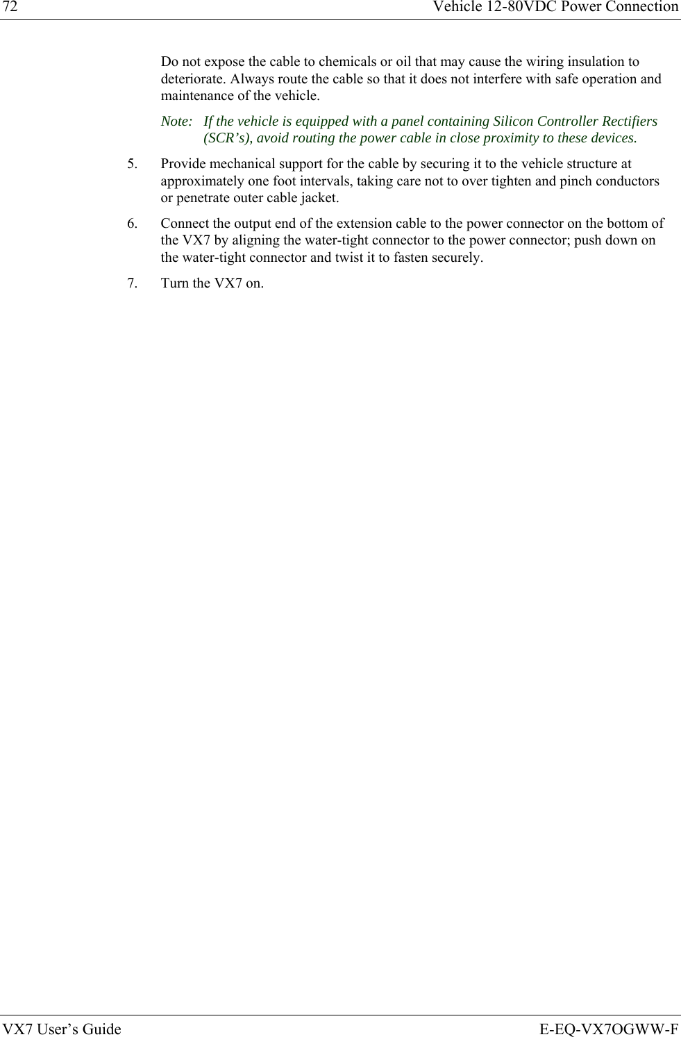

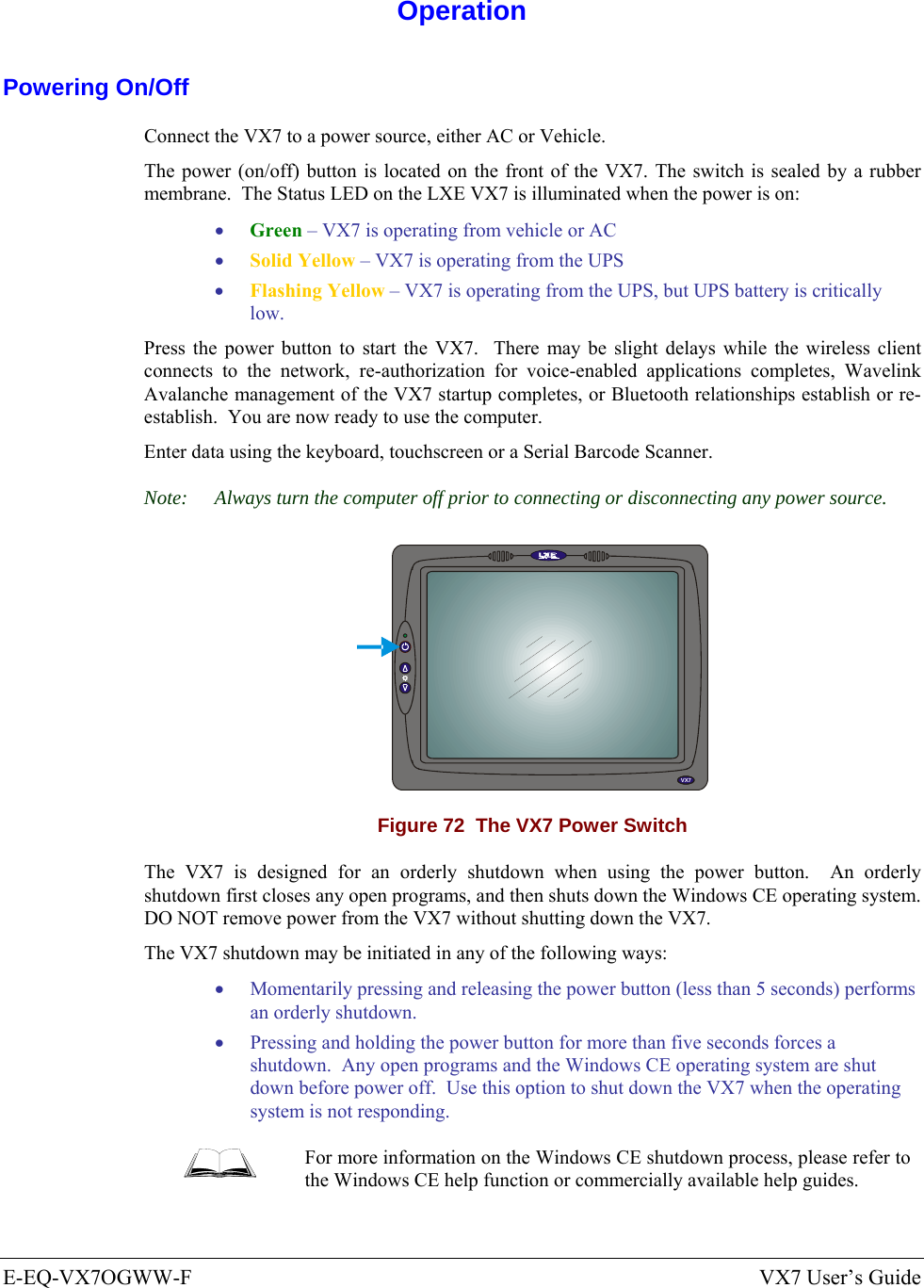
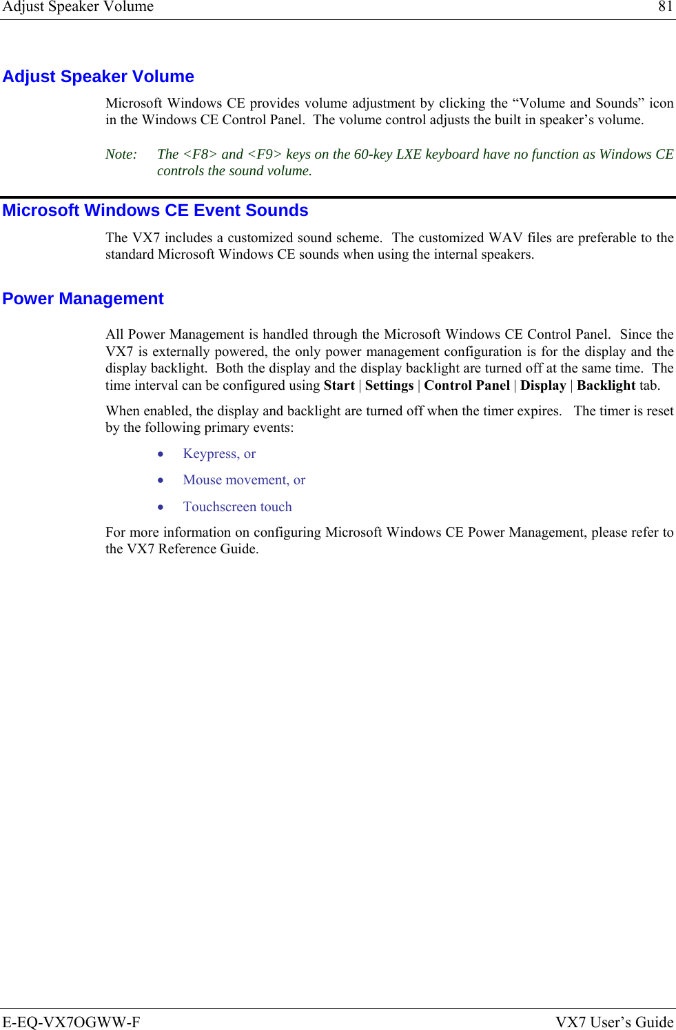
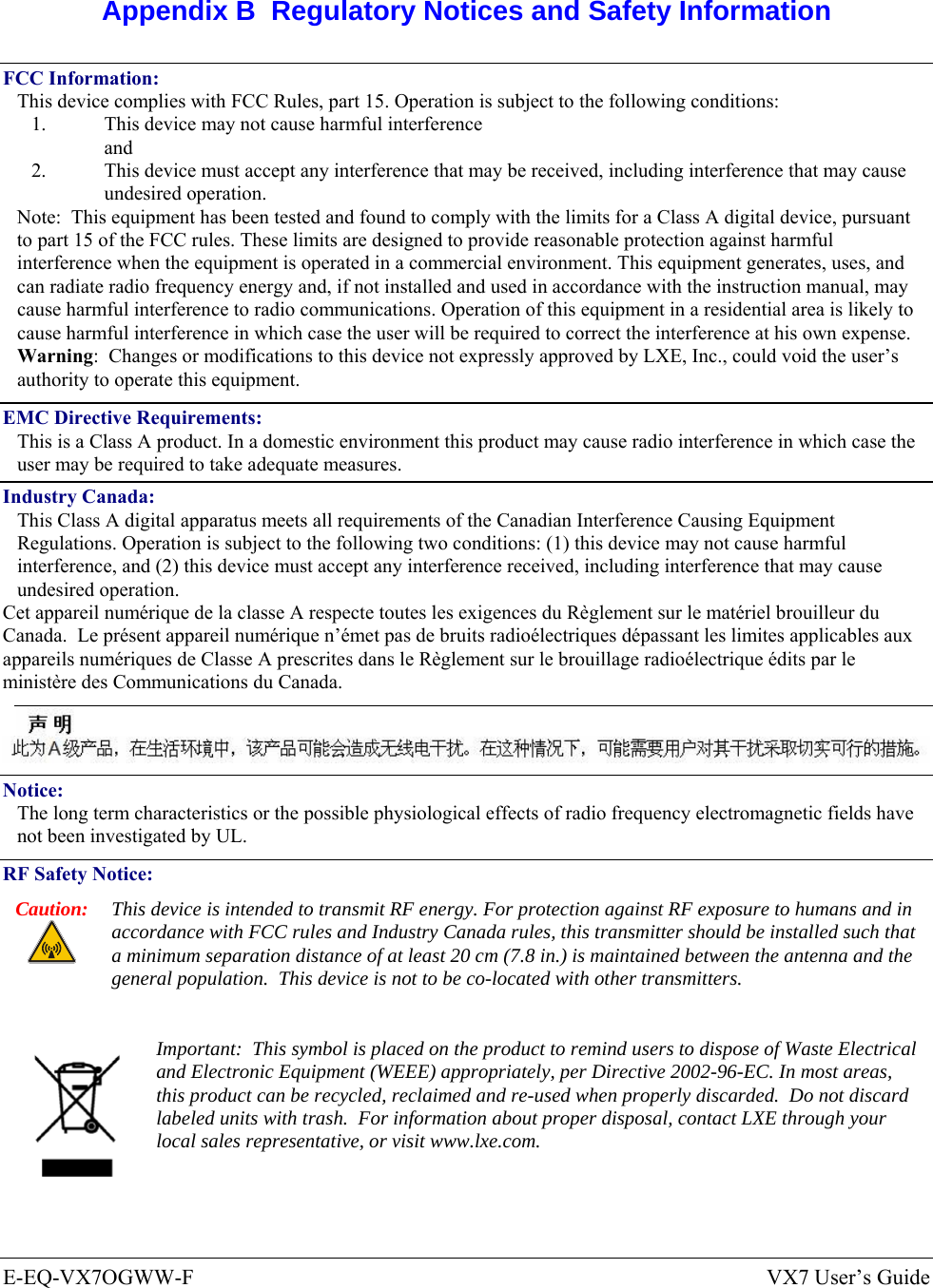
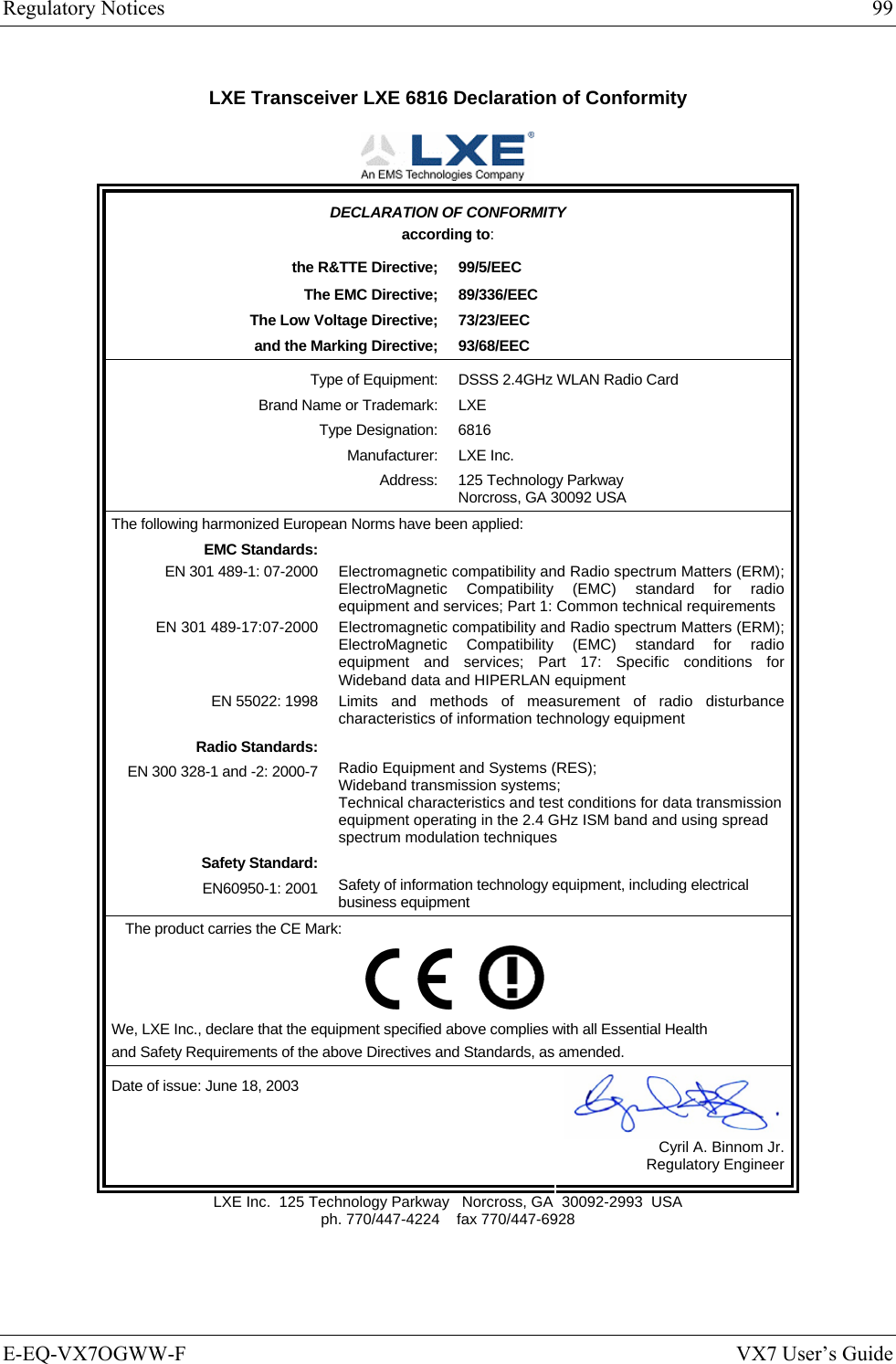
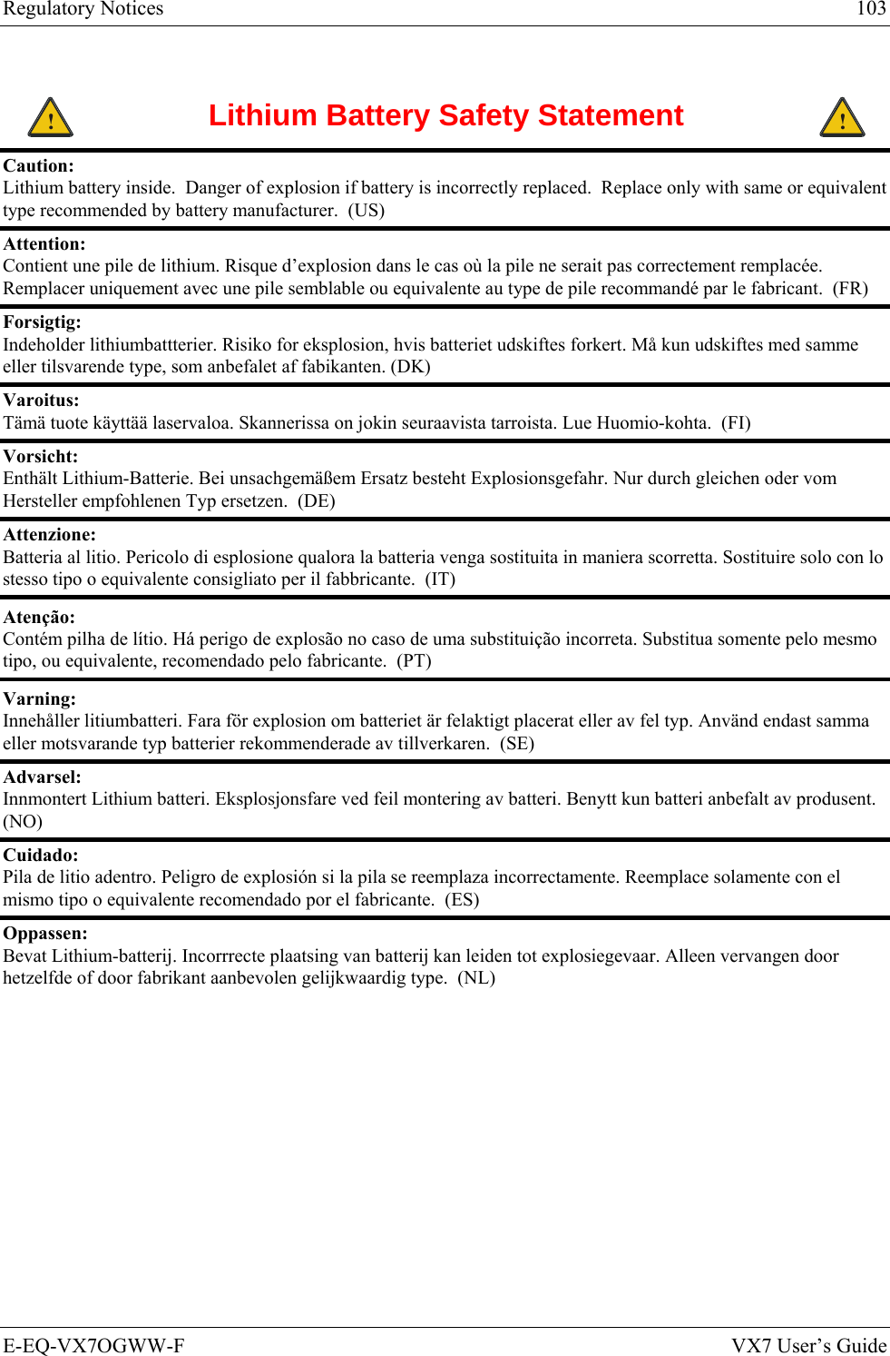
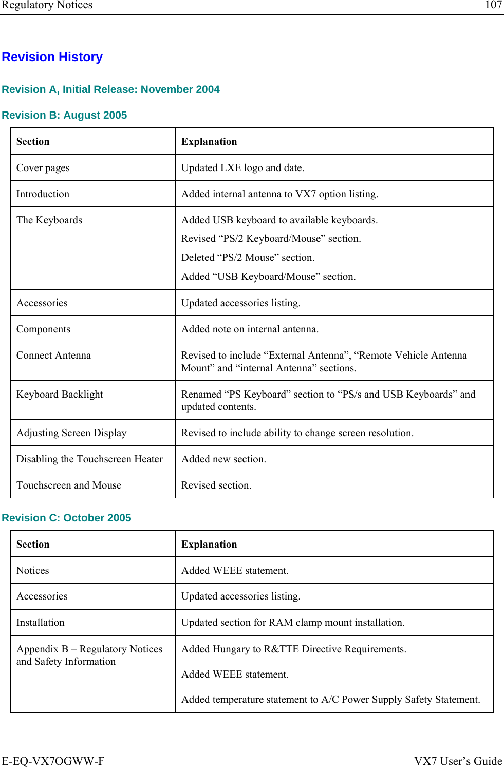
![E-EQ-VX7OGWW-F VX7 User’s Guide Appendix A Key Maps 95-key Keypad with Pointing Device Esc F2 F3 F4 F5 F6 F7 F8 F9 F10 F11 F12PrintScreenSysRq ScrollLock PauseBreakFn`1234567890-=BackSpaceNumLock/*-TabQWE R T Y U I OP[]\{}|7894561203Home PgUpCapsASDFGHJKL;':"EnterCtrl AltXCVBNM,./<>?ShiftAlt Ctrl InsEnd PgDn+~!@#$%^&*()_+LockShiftZLREnter.DelF1 Figure 77 95-Key LXE QWERTY Keyboard The key map table that follows lists the commands used for the VX7. Note that since the VX7 uses a Microsoft Windows CE operating system, no DOS Terminal Emulation keypress sequences are provided. Key Map 101-Key Equivalencies There are ten hidden keys on the 95-key keyboard. Each of these hidden keys is accessed by pressing the <Fn> key plus another key. To get this key Press These Keys and Then Insert Fn + 0 on the number pad Home Fn + 7 on the number pad Page Up Fn + 9 on the number pad Delete Fn + . on the number pad End Fn + 1 on the number pad Page Down Fn + 3 on the number pad Up Arrow Fn + 8 on the number pad Left Arrow Fn + 4 on the number pad Down Arrow Fn + 2 on the number pad Right Arrow Fn + 6 on the number pad Note: The 2nd key function is available on the 60-key keyboard only.](https://usermanual.wiki/Honeywell/LXE4830P.User-Manual-VX7-part-2/User-Guide-886701-Page-37.png)
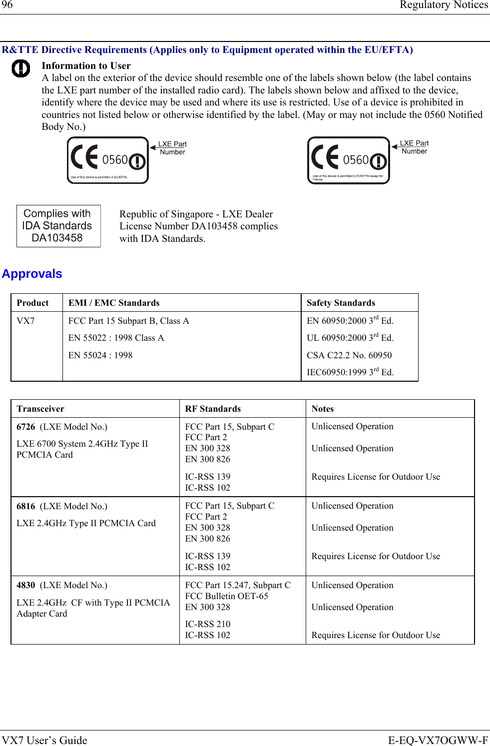
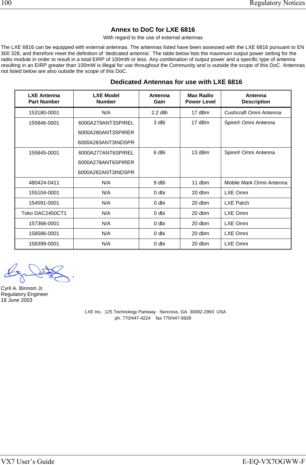
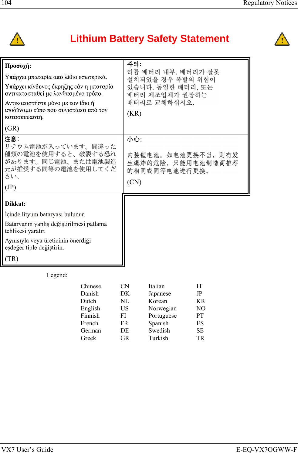
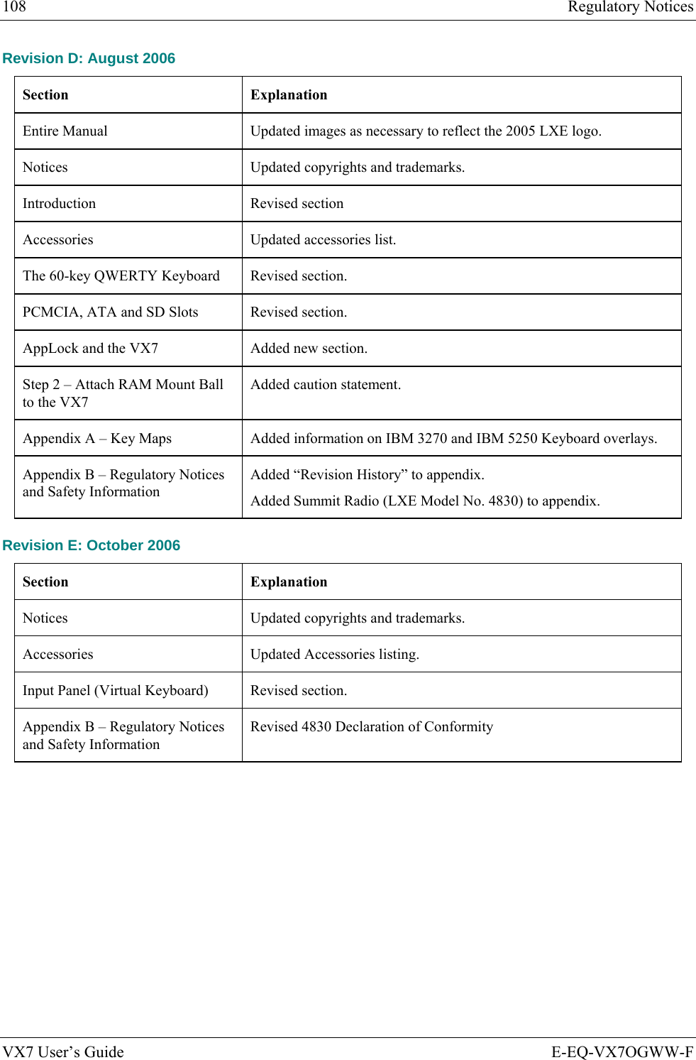
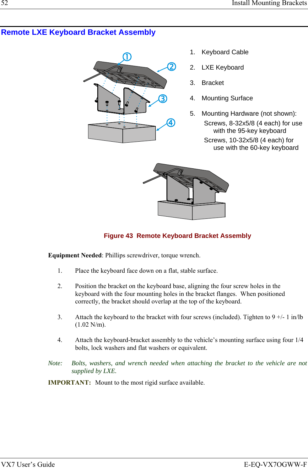
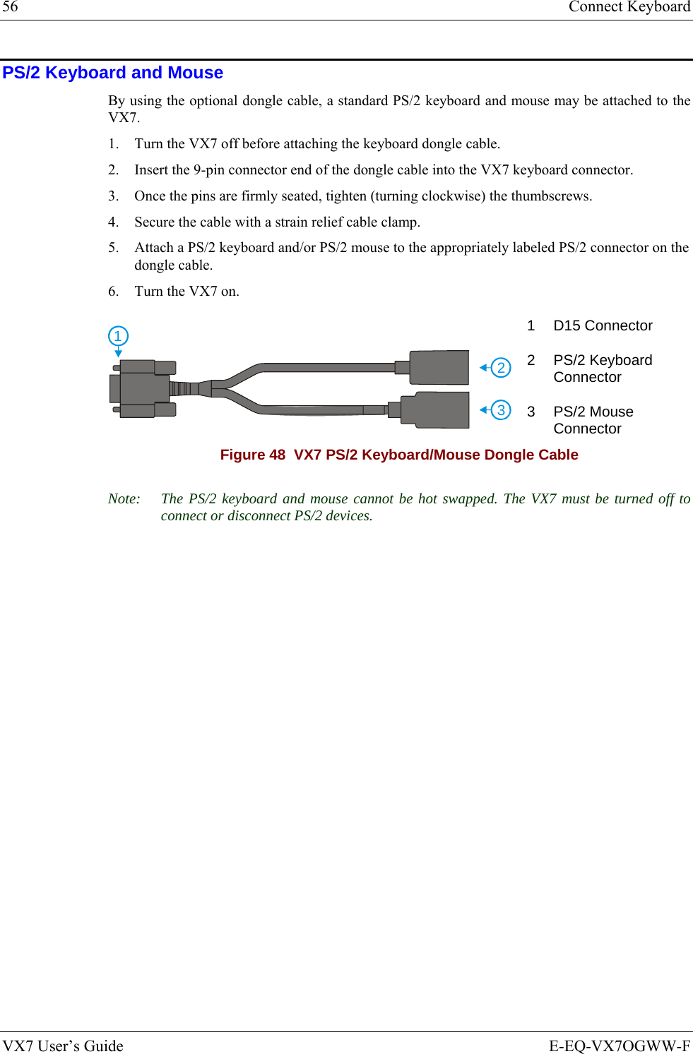
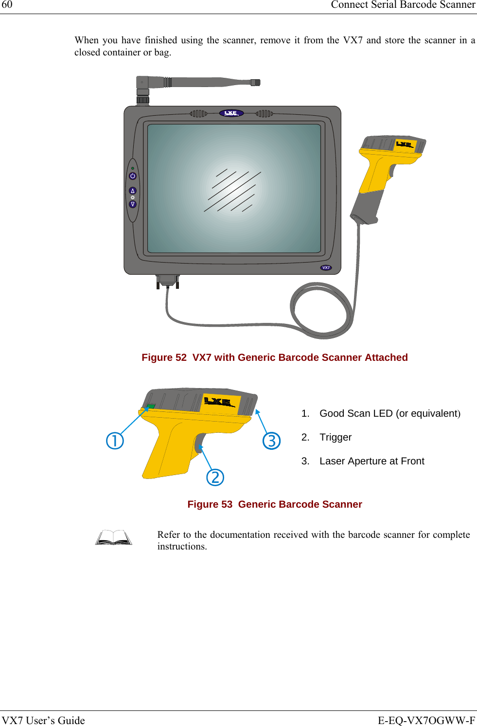
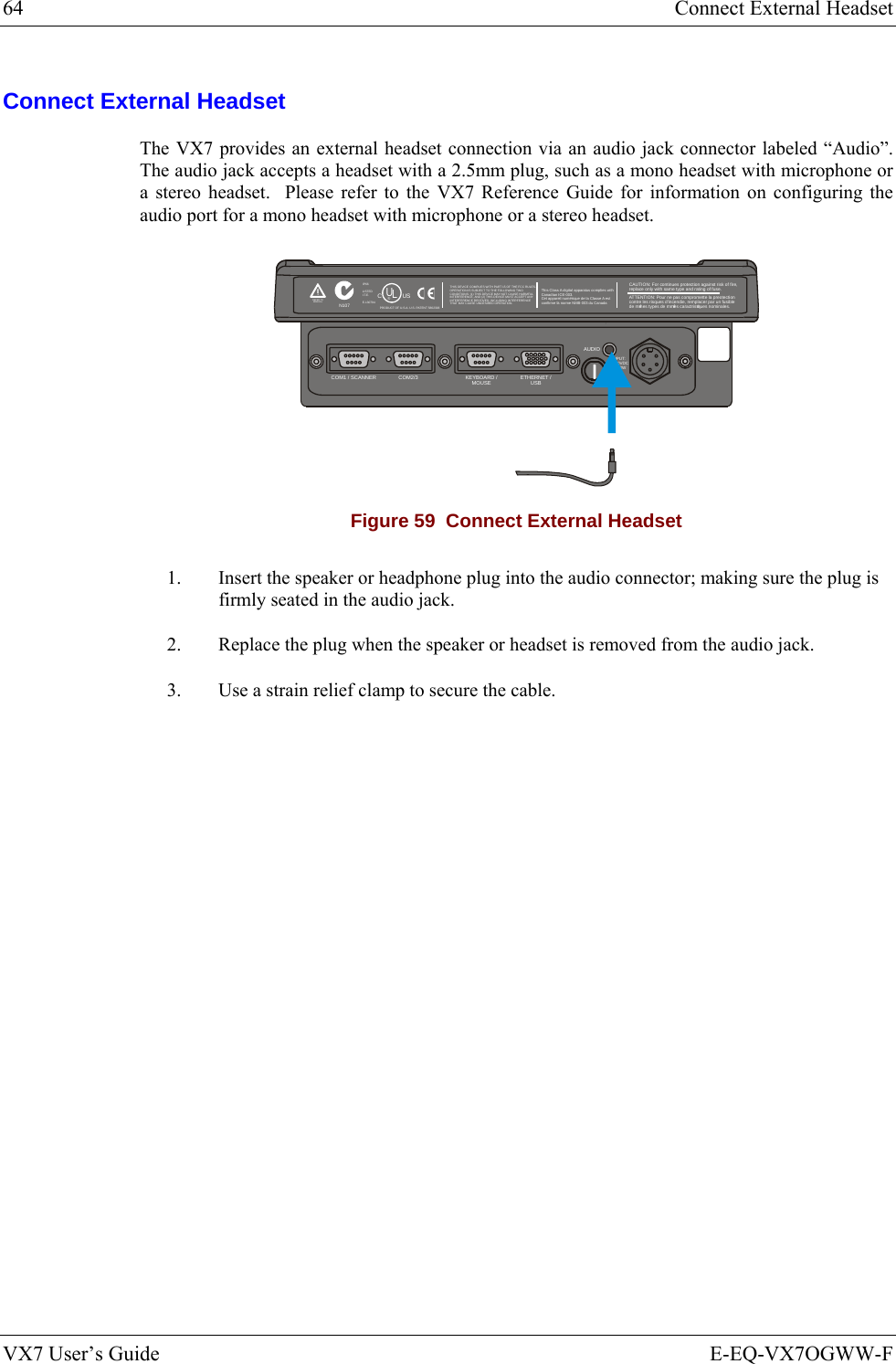
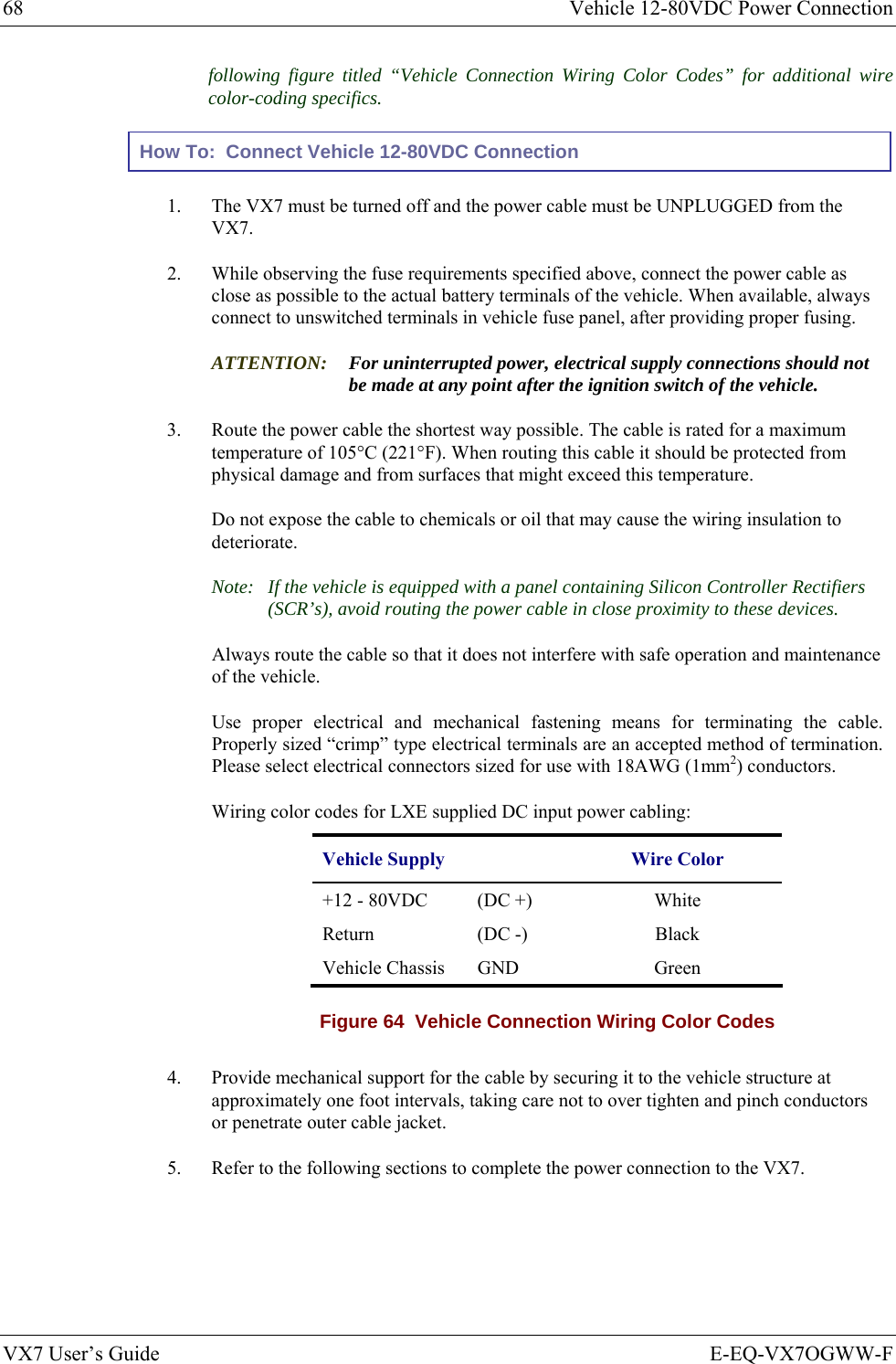
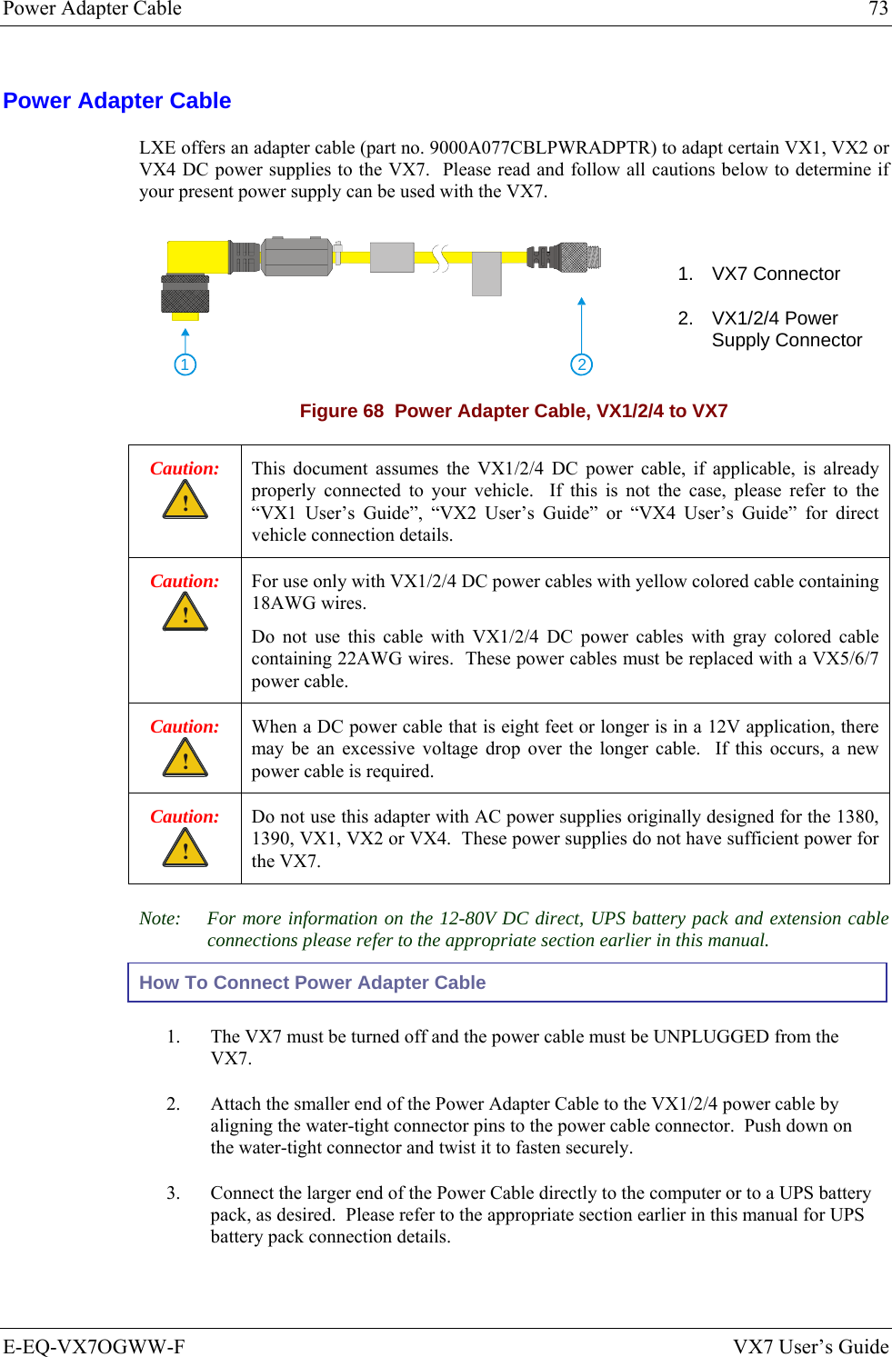
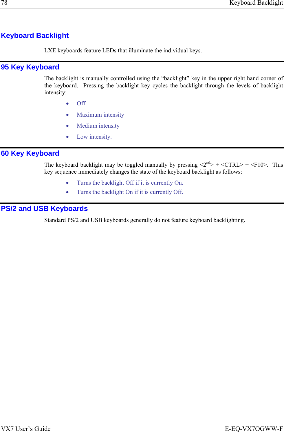
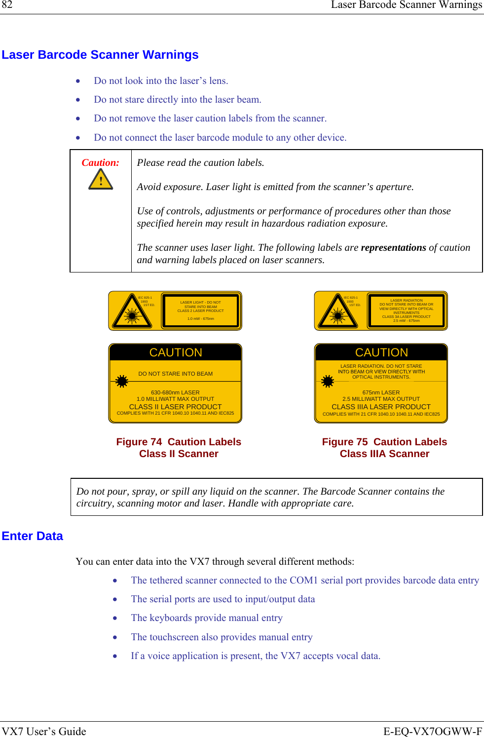
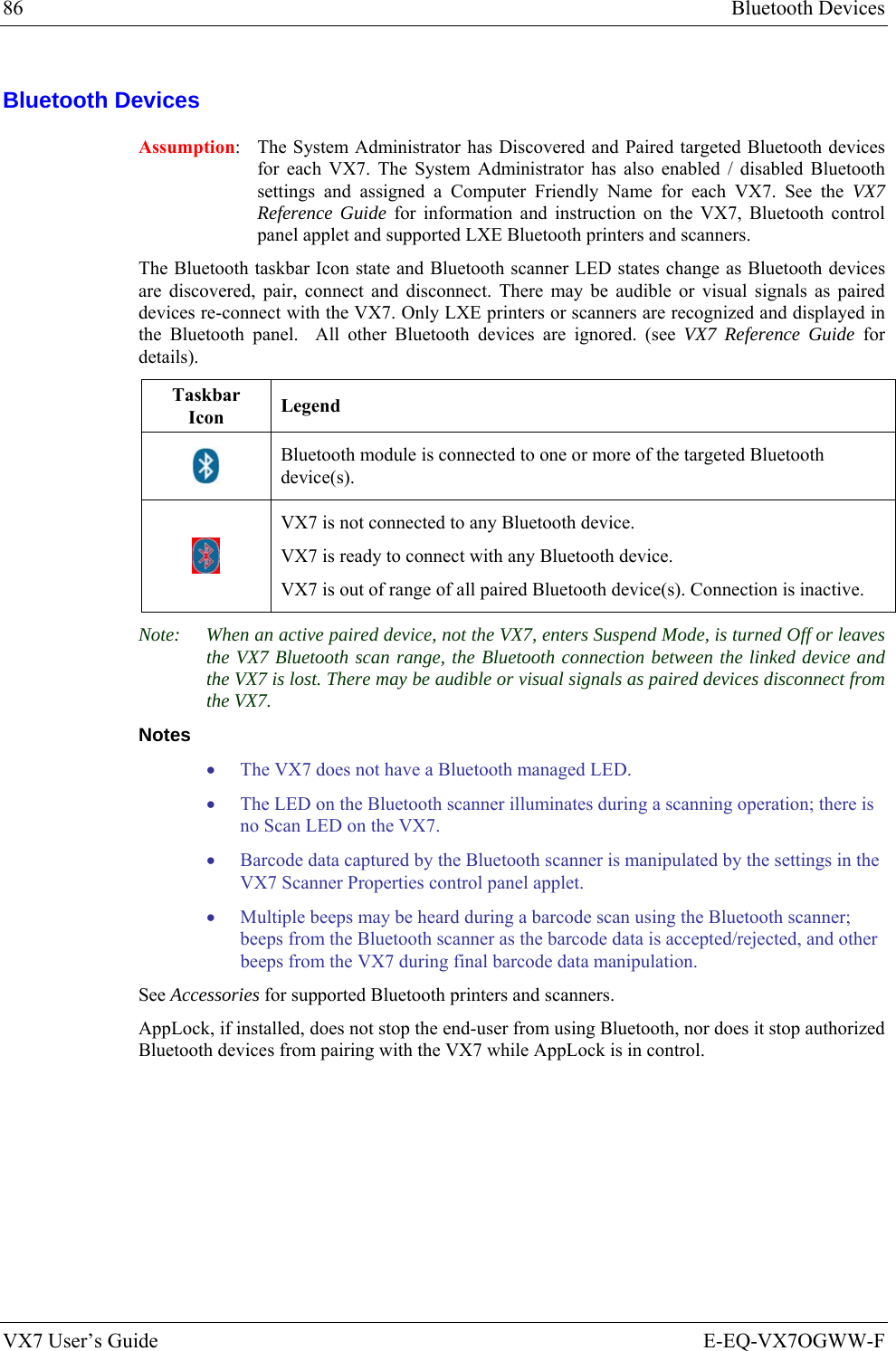
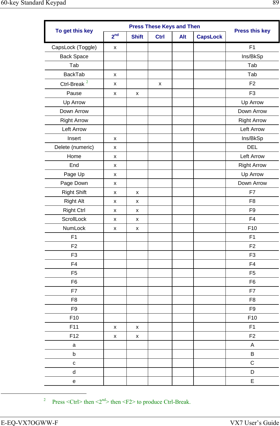
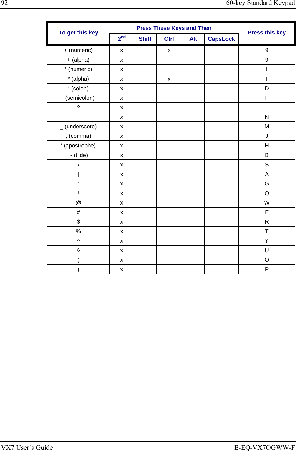
![88 60-key Standard Keypad VX7 User’s Guide E-EQ-VX7OGWW-F 60-key Standard Keypad ESCSHIFT2NDALT SPF1 F2 F3 F4 F5 F6 F7 F8 F9CAPS BREAK R/SBCMNADFGHJKLSVXZ@#$% ^&*()F10BKLTINSBKSPEIOPRTUWYCTRL !|\ :; ‘,.?~_Home ENDENTERPgUpPgDn0.1245/78-+={}[]><DEL369CAPS2nd Figure 78 60-Key LXE QWERTY Keyboard The key map table that follows lists the commands used for the VX7. Note that since the VX7 uses a Microsoft Windows CE operating system, no DOS Terminal Emulation keypress sequences are provided. Key Map 101-Key Equivalencies When using a sequence of keys that includes the <2nd> key, press the <2nd> key first then the rest of the key sequence. Note: This keyboard does not have a NumLock indicator. NumLock is enabled by default. The warmboot behavior of NumLock can be configured. Please refer to the “VX7 Reference Guide”. When NumLock is off, only the numeric 0 through 9 and DOT keys are affected. All other keymaps are unchanged. When the VX7 boots, the default condition of Caps (or CapsLock) is Off. The Caps (or CapsLock) condition can be set toggled with a <2nd>+<F1> key sequence. The CAPS LED on the keyboard is illuminated when CapsLock is On. Press These Keys and Then To get this key 2nd Shift Ctrl Alt CapsLock Press this key Keyboard Backlight x x F10 Suspend/Resume 1 x F3 2nd 2nd Shift Shift Alt Alt Ctrl Ctrl Esc Esc Space Sp Enter Enter Enter (numeric) x Enter 1 The Suspend/Resume key has no function as Windows Power Management controls the power management modes.](https://usermanual.wiki/Honeywell/LXE4830P.User-Manual-VX7-part-2/User-Guide-886701-Page-38.png)
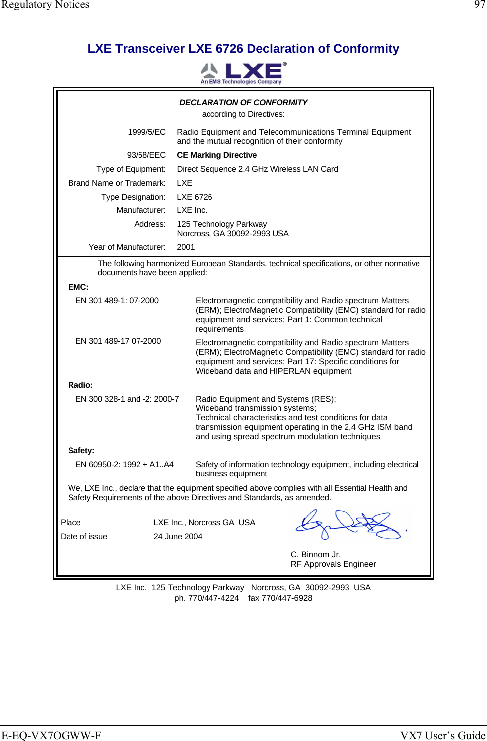
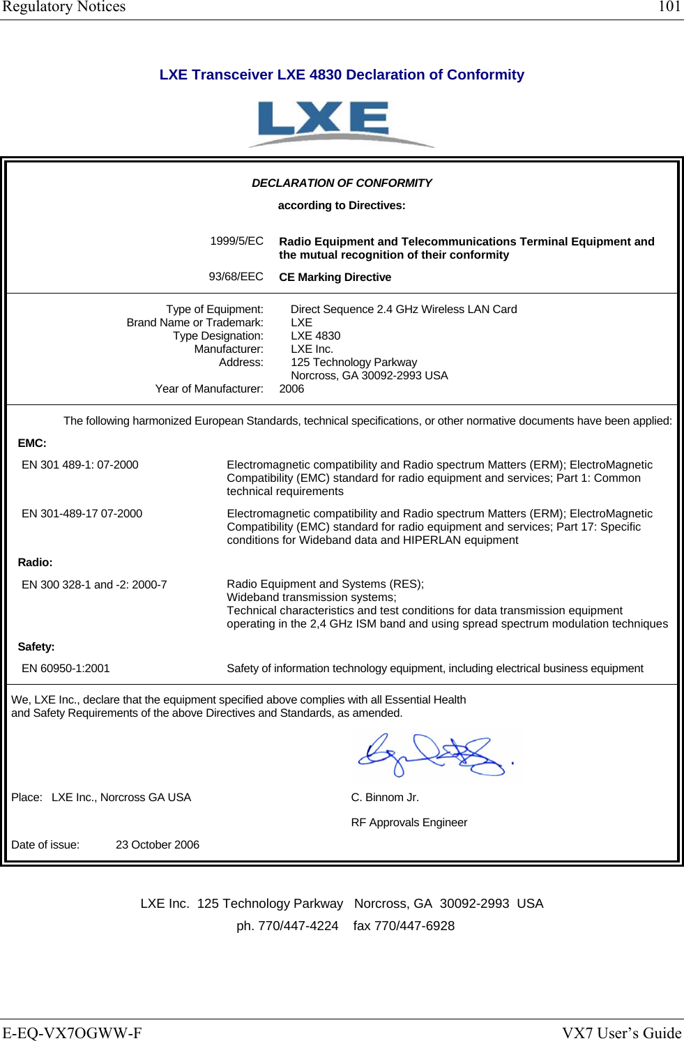
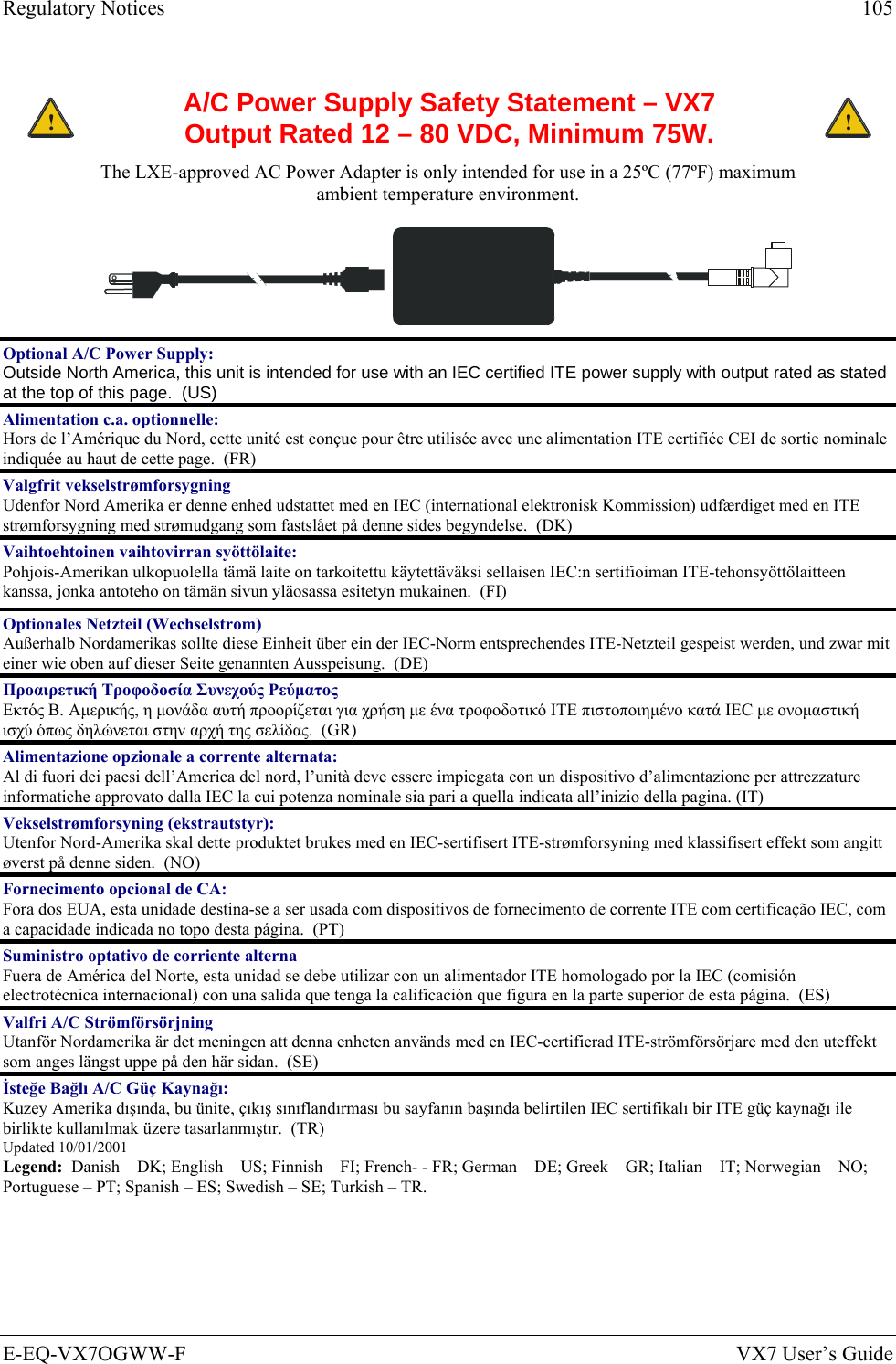
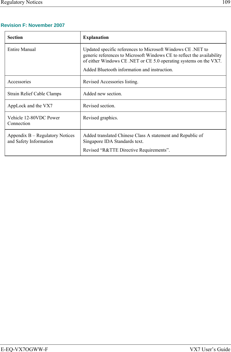
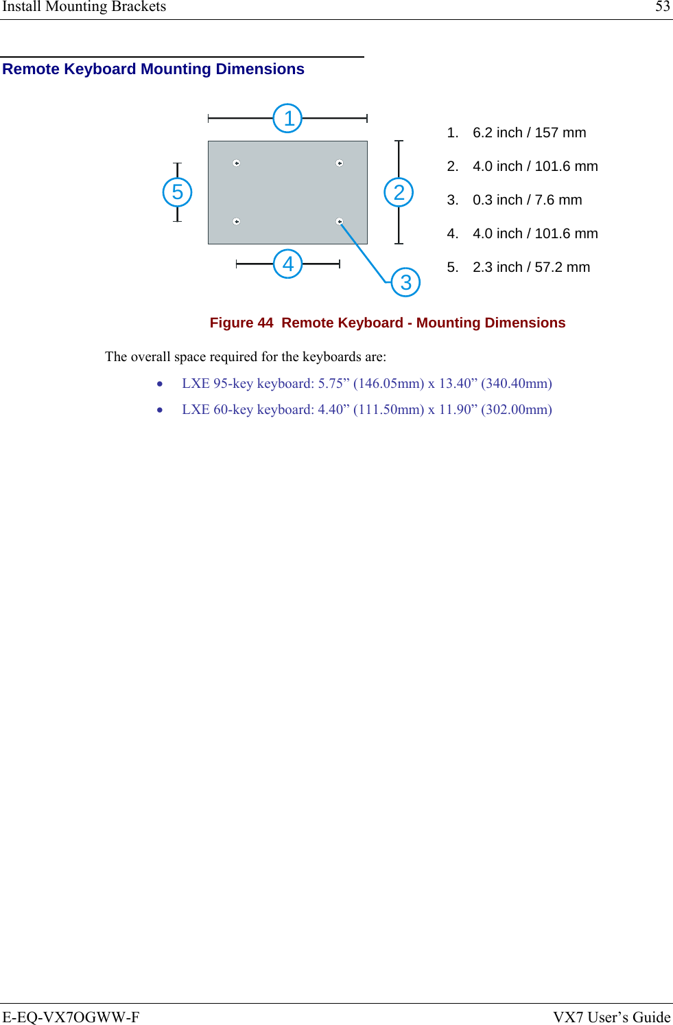
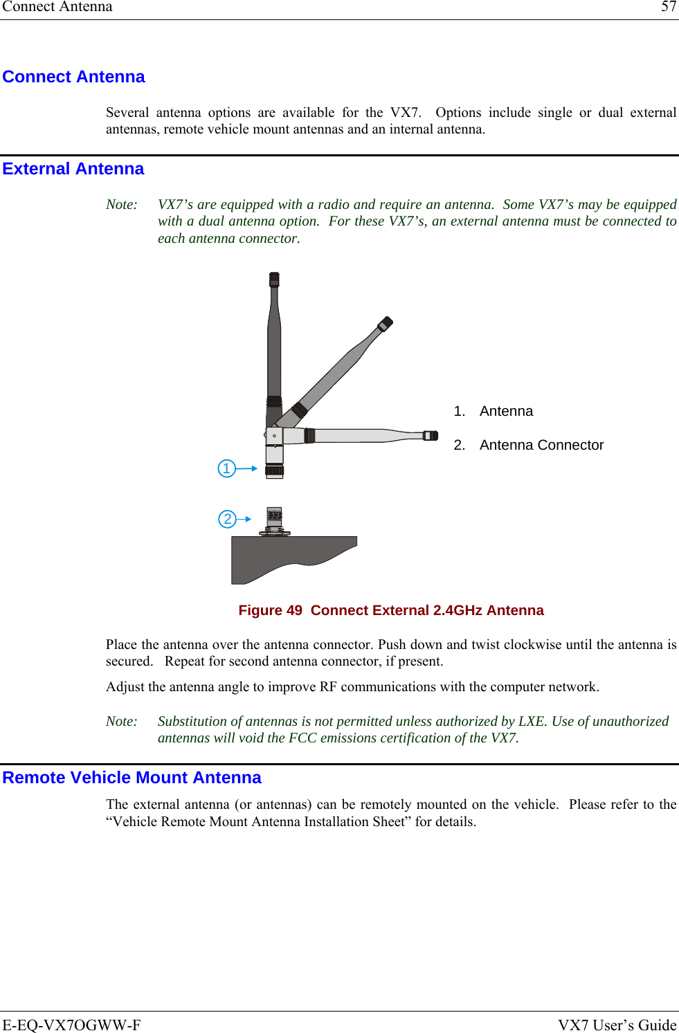
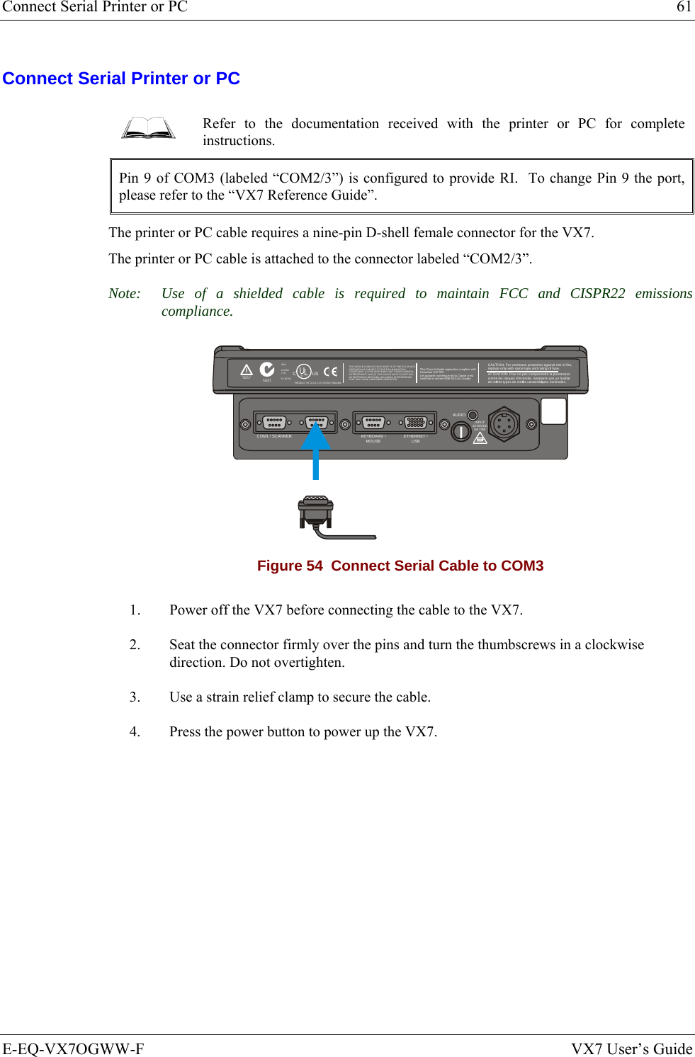
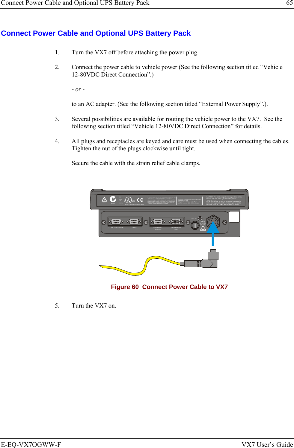
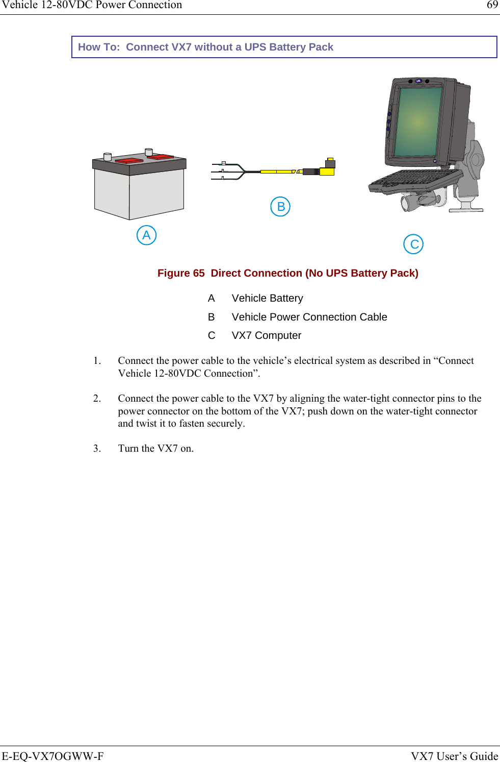
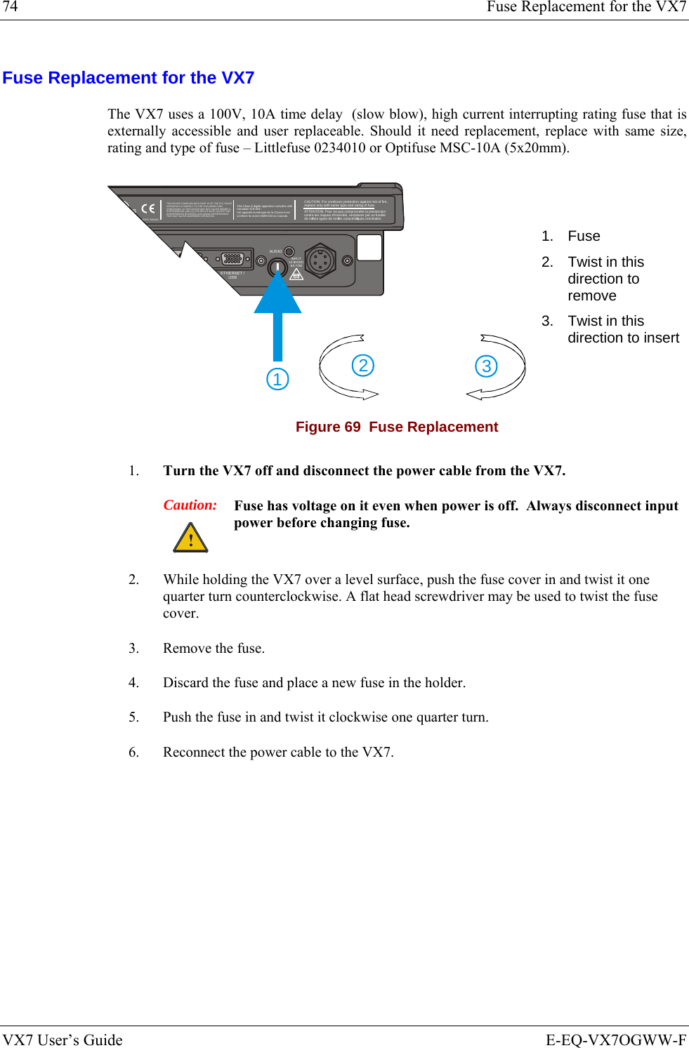
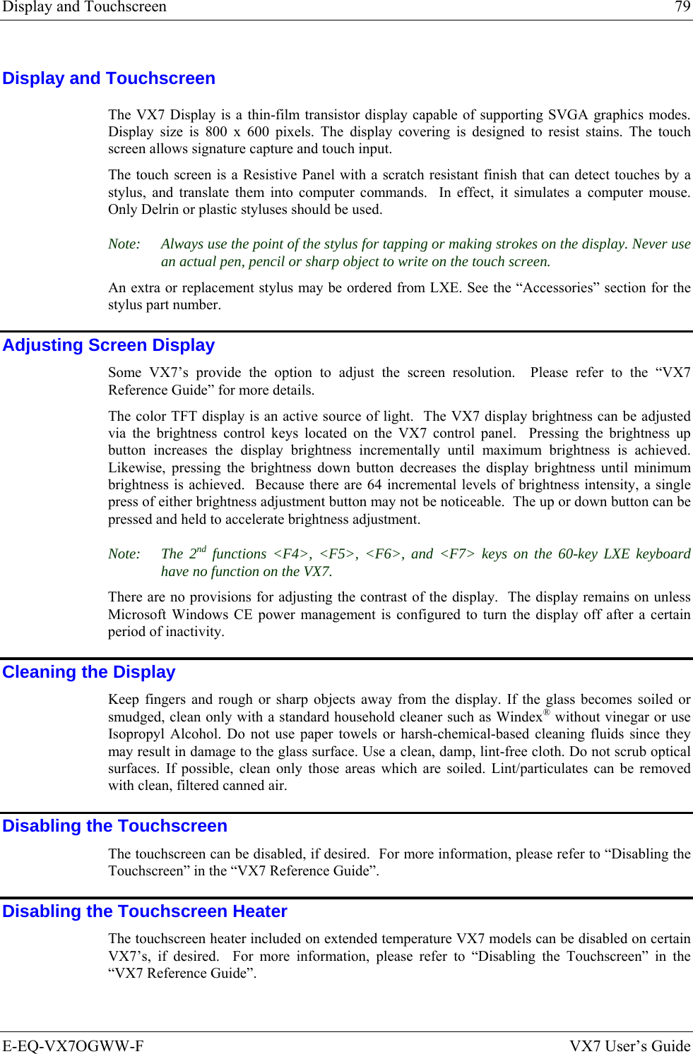
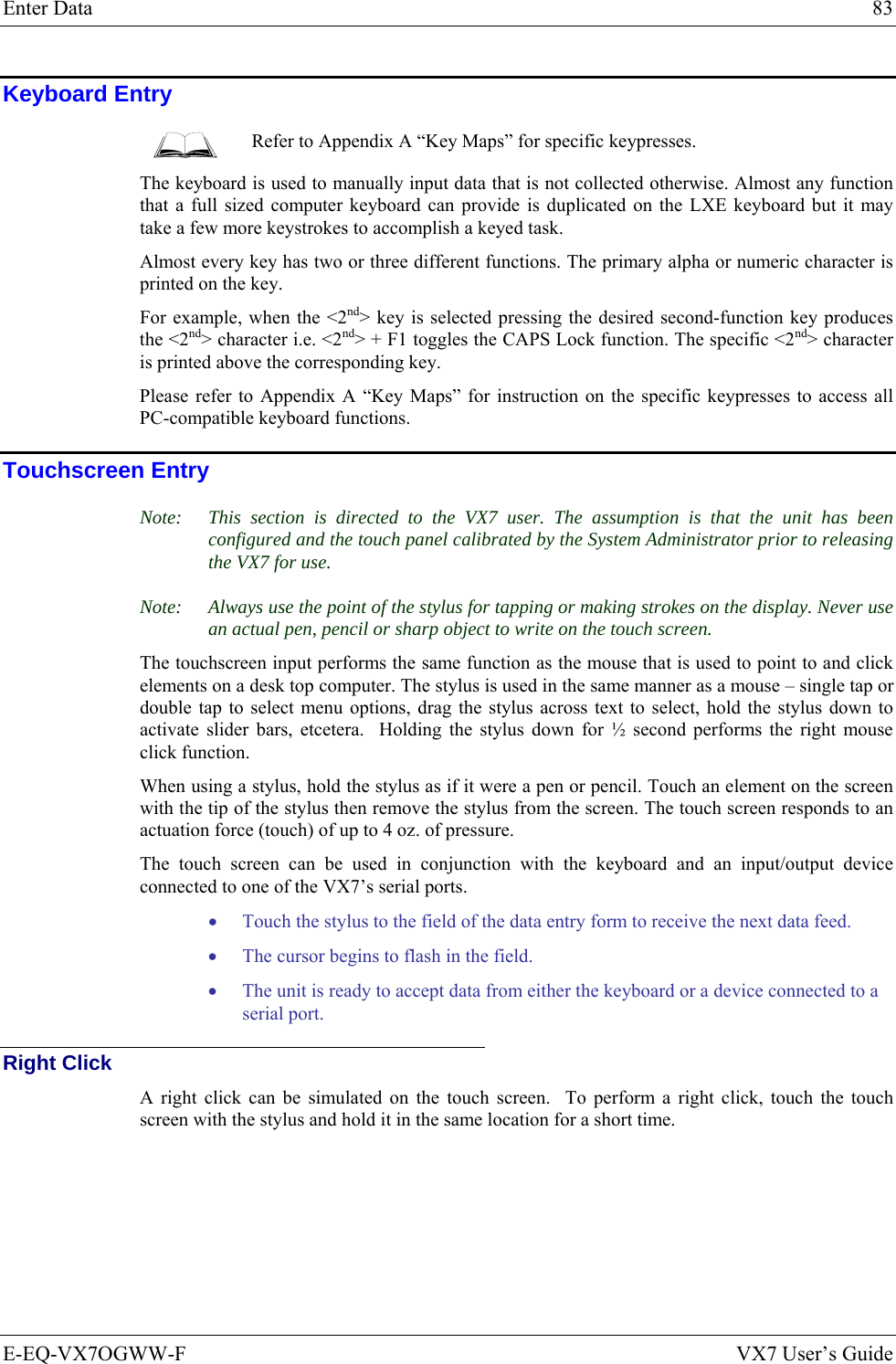
![60-key Standard Keypad 91 E-EQ-VX7OGWW-F VX7 User’s Guide Press These Keys and Then To get this key 2nd Shift Ctrl Alt CapsLock Press this key T x T U x U V x V W x W X x X Y x Y Z x Z 1 (alpha) x x 1 2 (alpha) x x 2 3 (alpha) x x 3 4 (alpha) x x 4 5 (alpha) x x 5 6 (alpha) x x 6 7 (alpha) x x 7 8 (alpha) x x 8 9 (alpha) x x 9 0 (alpha) x x 0 DOT (alpha) x K 1 (numeric) 1 2 (numeric) 2 3 (numeric) 3 4 (numeric) 4 5 (numeric) 5 6 (numeric) 6 7 (numeric) 7 8 (numeric) 8 9 (numeric) 9 0 (numeric) 0 DOT (numeric) DOT < x 0 [ x 1 ] x 2 > x 3 = x 4 { x 5 } x 6 / (numeric) x x 7 / (alpha) x 7 - (numeric) x x 8 - (alpha) x 8](https://usermanual.wiki/Honeywell/LXE4830P.User-Manual-VX7-part-2/User-Guide-886701-Page-41.png)
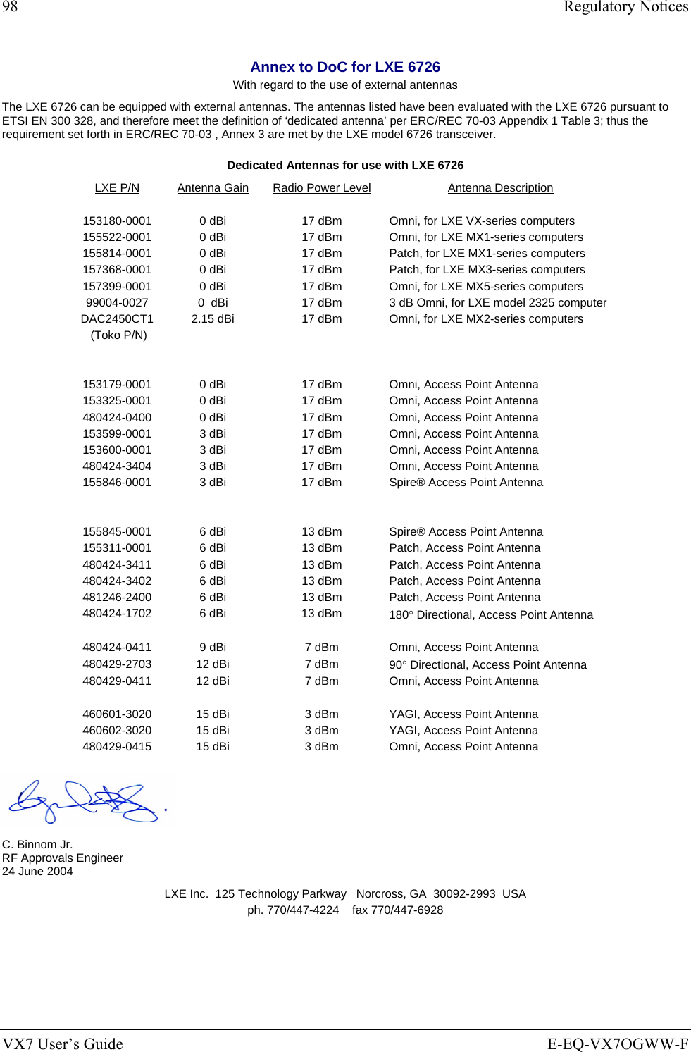
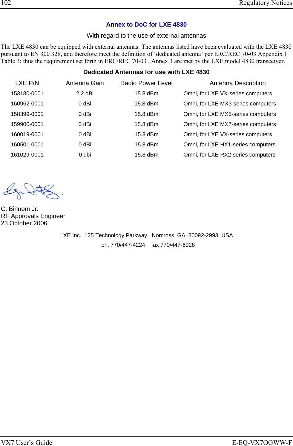
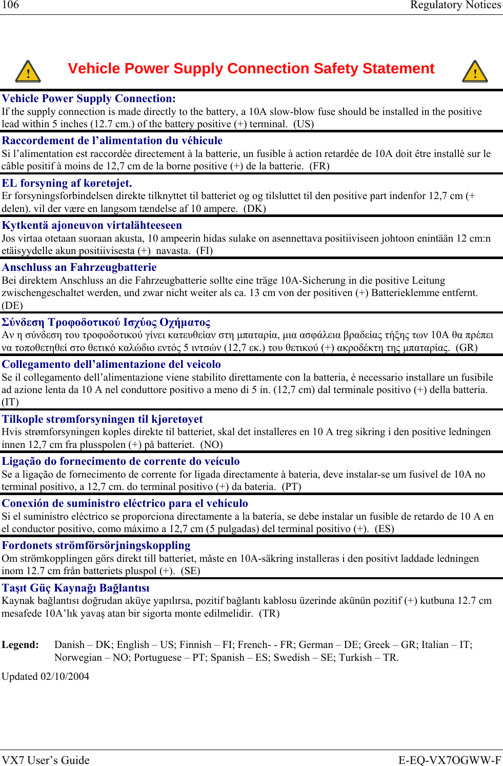
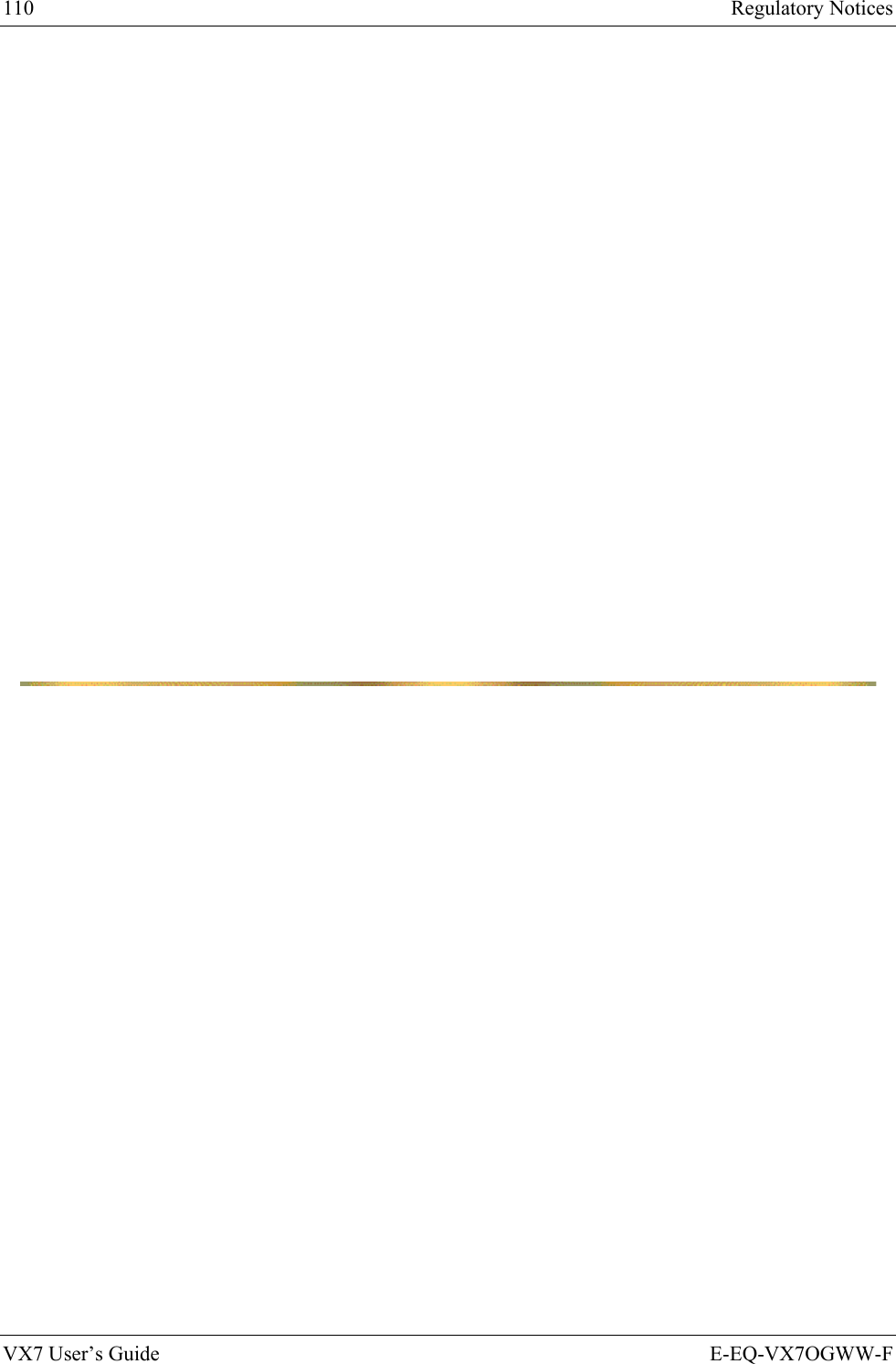
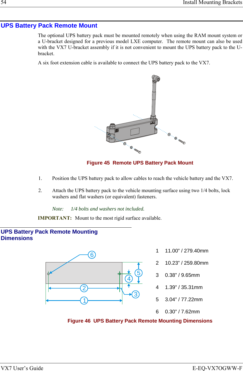
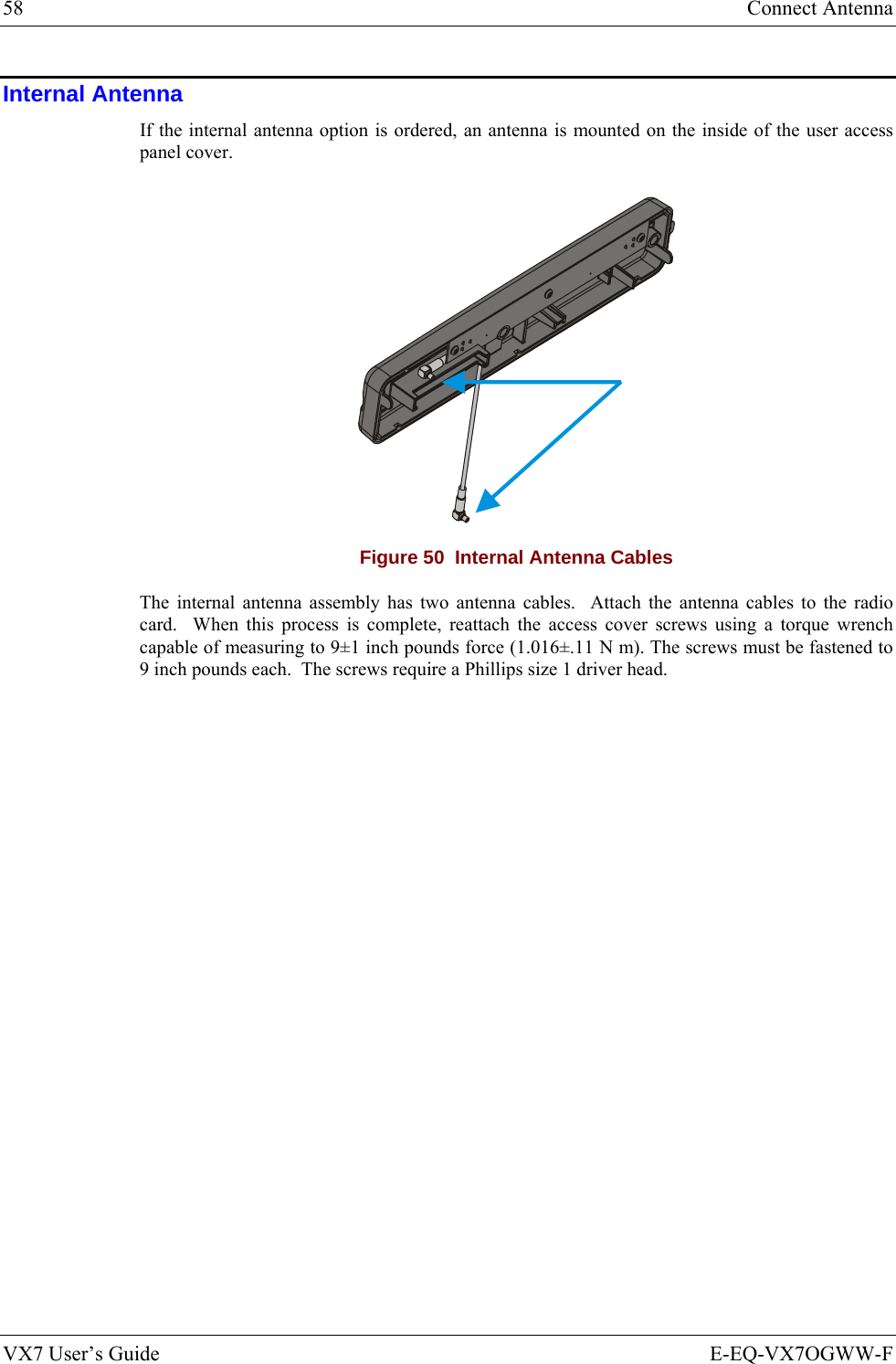
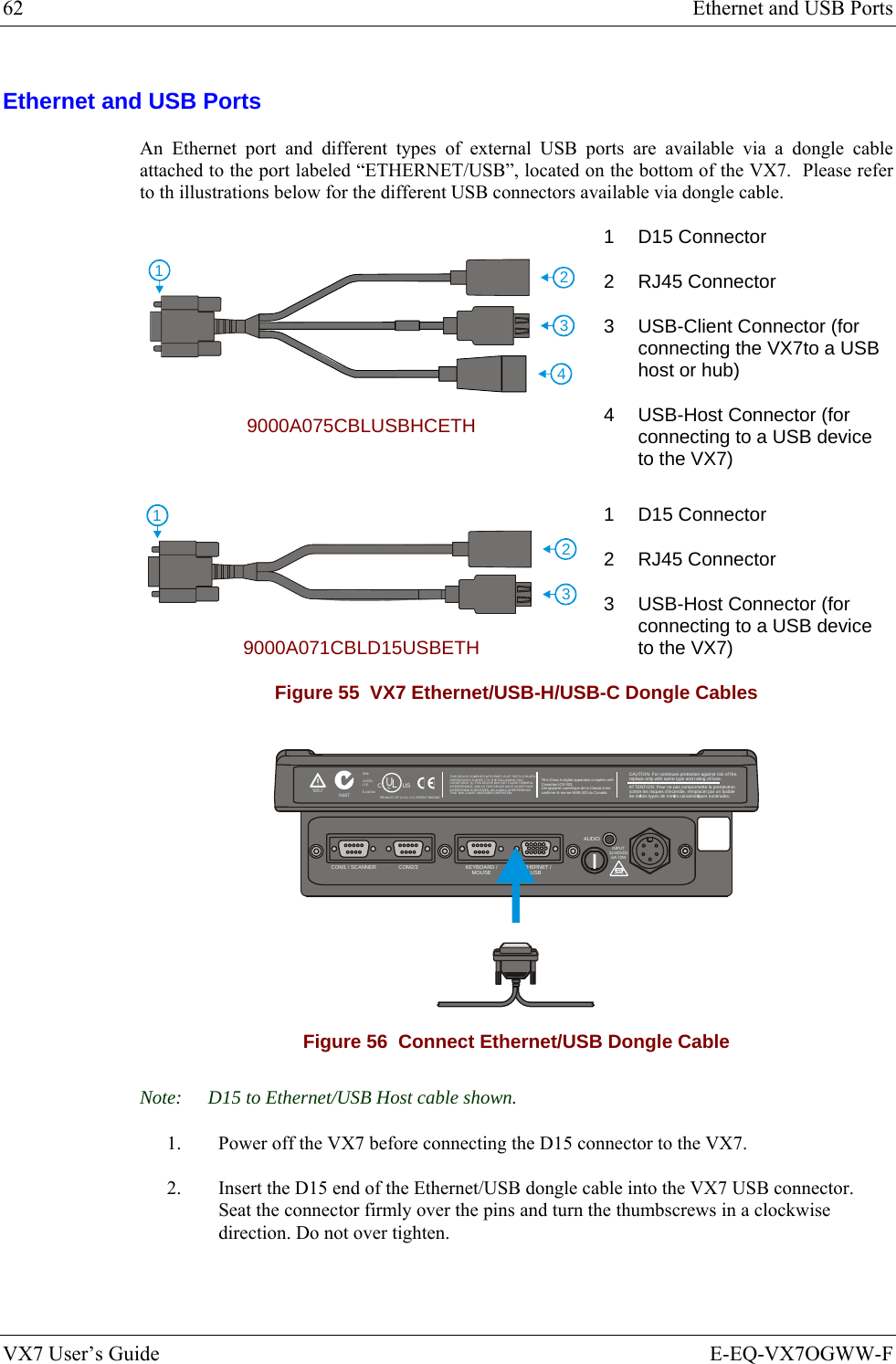
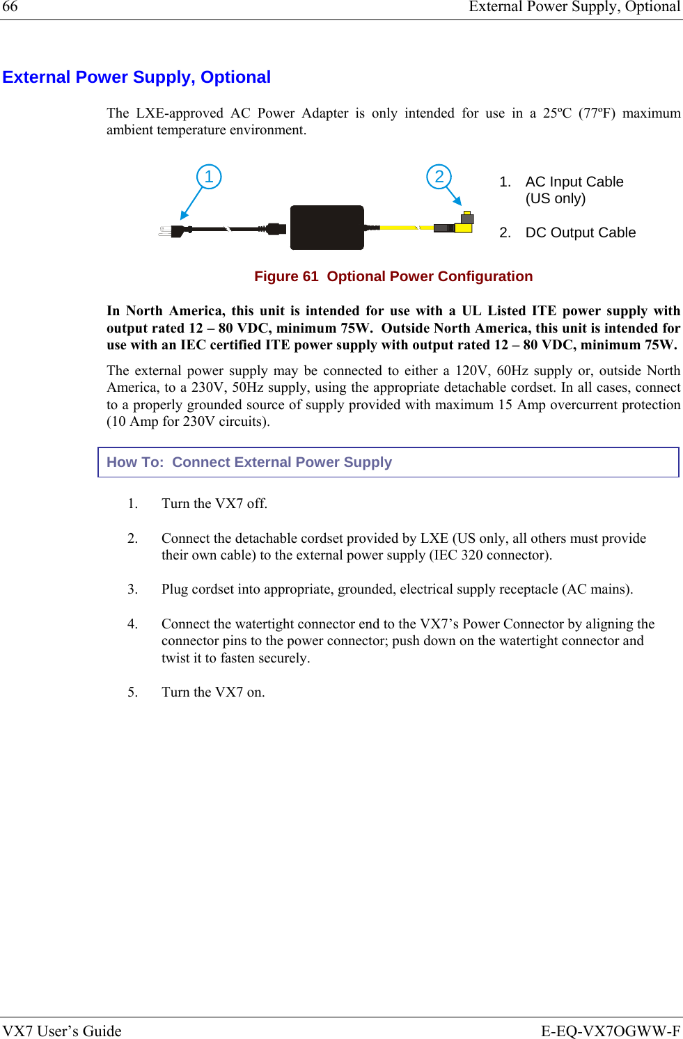
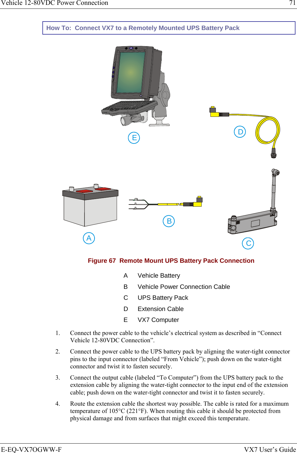
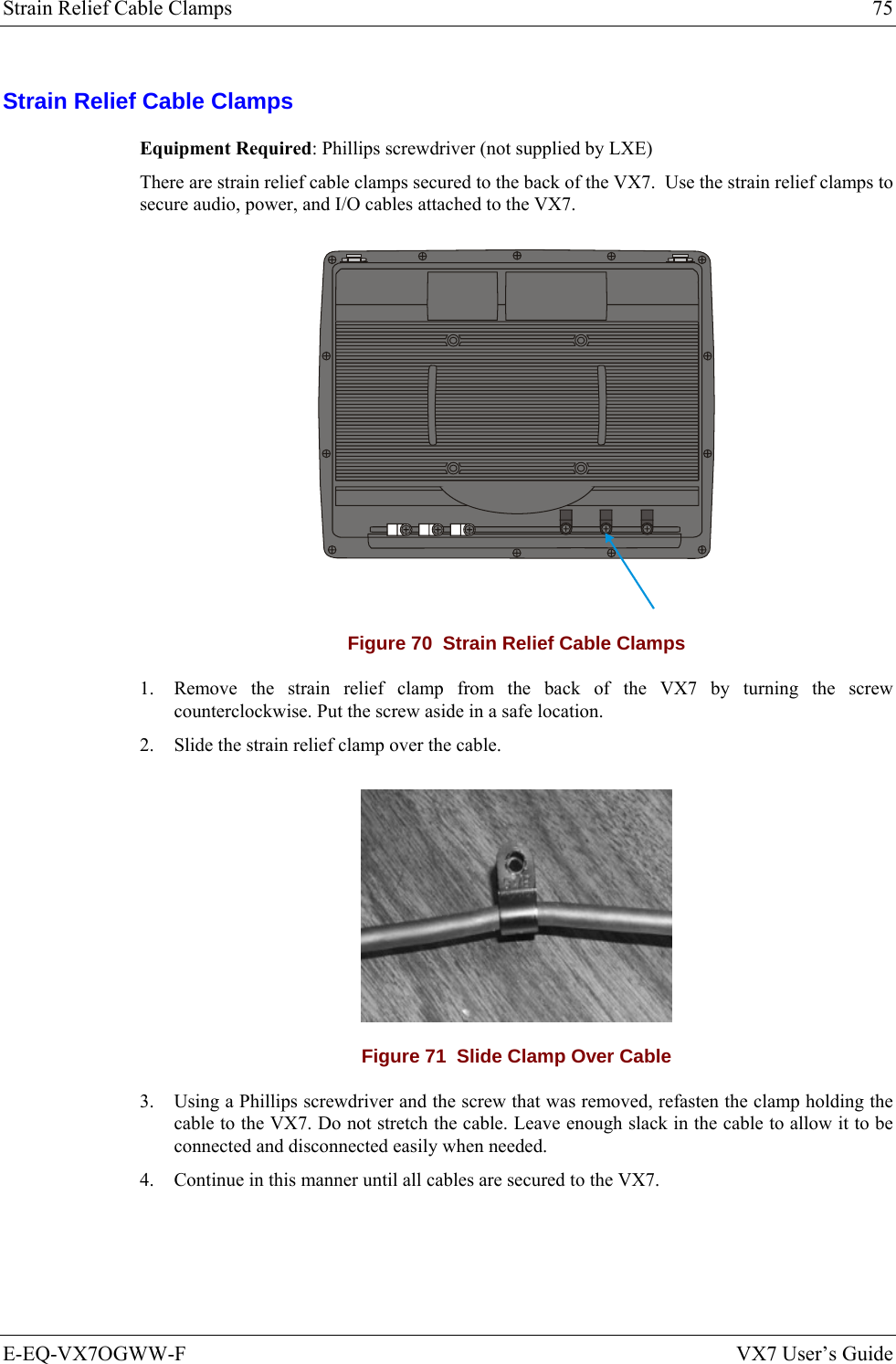
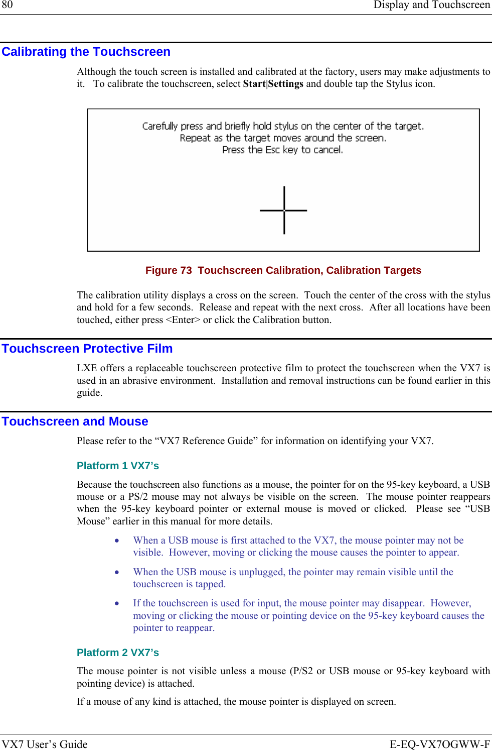
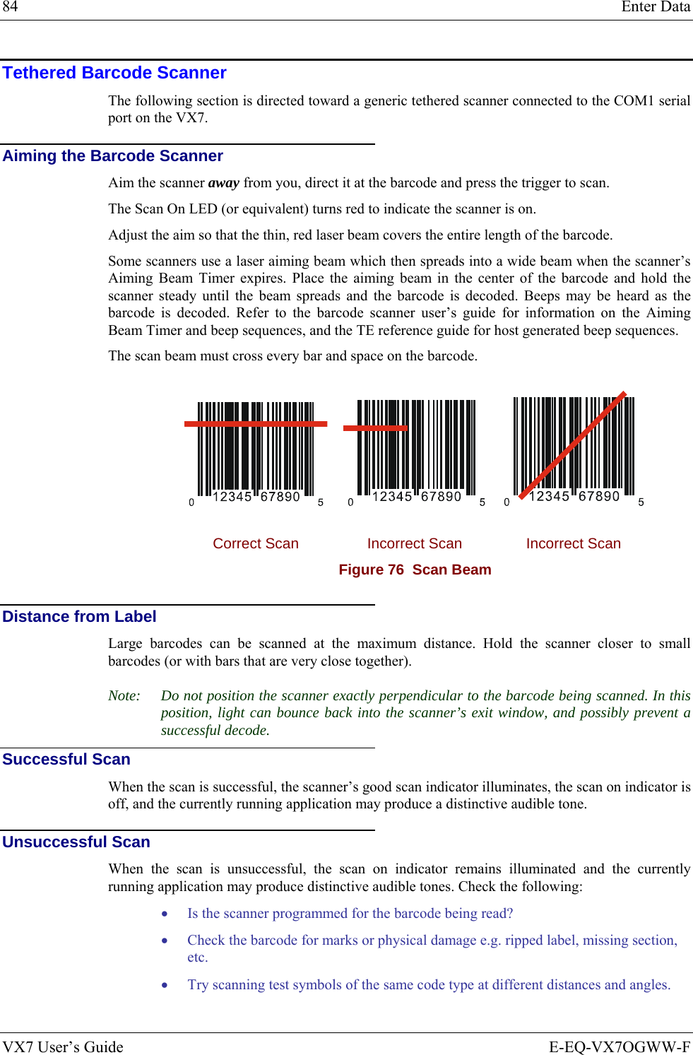
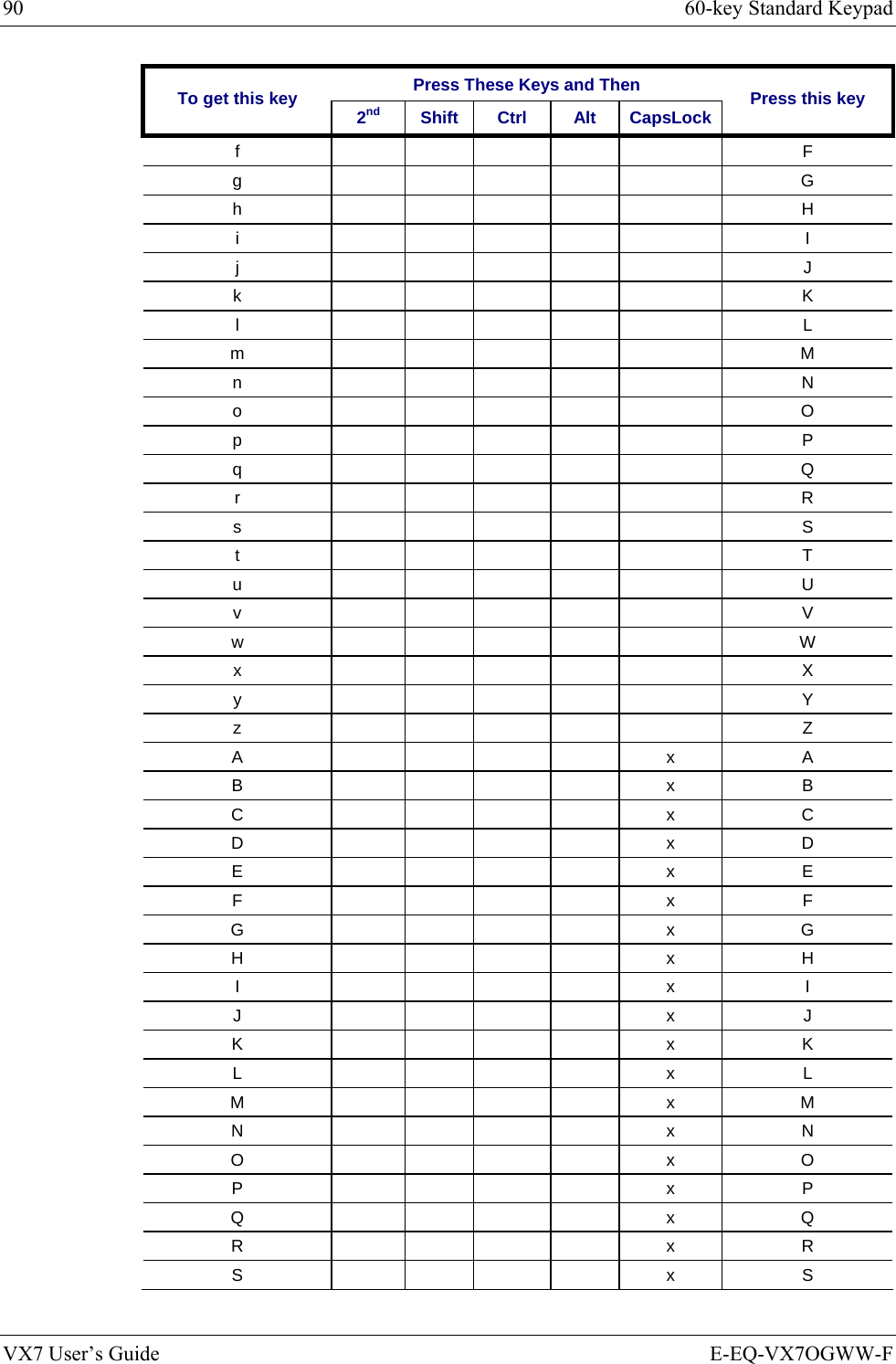
![60-key Standard Keypad 93 E-EQ-VX7OGWW-F VX7 User’s Guide IBM 3270 Keypad Overlay ESCSHIFT2NDALT SPF1 F2 F3 F4 F5 F6 F7 F8 F9CAPS BREAK R/SBCMNADFGHJKLSVXZ@#$% ^&*()F10BKLTINSBKSPEIOPRTUWYCTRL !|\ :; ‘,.?~_Home ENDENTERPgUpPgDn0.1245/78-+={}[]><DEL369Attn SysReq DelClr NLIns E-InpCAPS2ndRstPA1 PA2 PA3 Figure 79 IBM 3270 Specific Keypad The 60-key keypad is available with an IBM 3270 overlay designed to allow the user to enter terminal emulator commands when running LXE’s RFTerm™ program. When running this program please refer to the following reference guide for equivalent keys and keypress sequences: • RFTerm™ Reference Guide IBM 5250 Keypad Overlay ESCSHIFT2NDALT SPF1 F2 F3 F4 F5 F6 F7 F8 F9CAPS BREAK R/SBCMNADFGHJKLSVXZ@#$% ^&*()F10BKLTINSBKSPEIOPRTUWYCTRL !|\ :; ‘,.?~_Home ENDENTERPgUpPgDn0.1245/78-+={}[]><DEL369Attn SysReq DelClrDupNLInsFld+Fld-E-InpField ExitCAPS2nd Figure 80 IBM 5250 Specific Keypad The 60-key keypad is available with an IBM 5250 overlay designed to allow the user to enter terminal emulator commands when running LXE’s RFTerm™ program. When running this program please refer to the following reference guide for equivalent keys and keypress sequences: • RFTerm™ Reference Guide](https://usermanual.wiki/Honeywell/LXE4830P.User-Manual-VX7-part-2/User-Guide-886701-Page-43.png)