Honeywell LXE4830P 802.11g COMPACT FLASH MODULE User Manual MX3X User s Guide
Honeywell International, Inc. 802.11g COMPACT FLASH MODULE MX3X User s Guide
Contents
- 1. Manual HX1 rev3
- 2. Manual MX3X rev3
- 3. Manual MX5X rev3
- 4. Manual MX7 rev3
- 5. User Manual HX2
- 6. User Manual MX7
- 7. users manual
- 8. USERS MANUAL
- 9. User Manual MX3X
- 10. User Manual VX3X
- 11. User Manual VX6 part 1
- 12. User Manual VX6 part 2
- 13. User Manual VX7 part 1
- 14. User Manual VX7 part 2
- 15. Users Manual F300
- 16. Users Manual MX9
User Manual MX3X


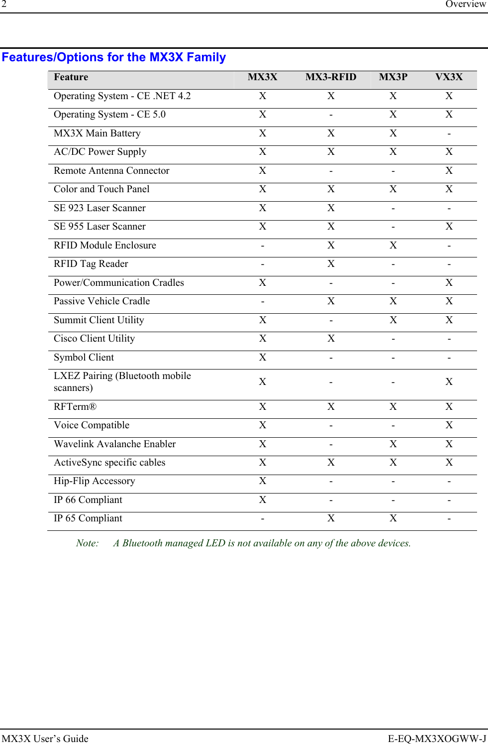
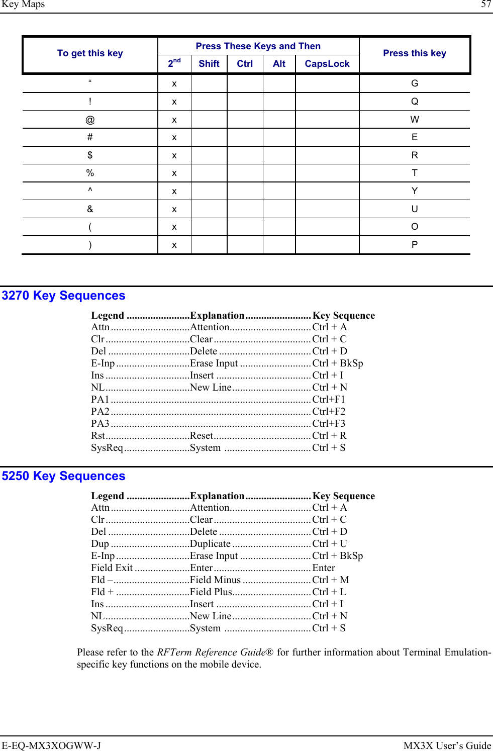
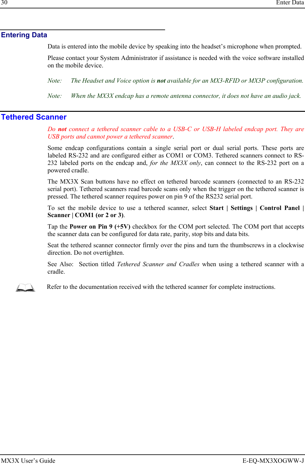
![4 Overview MX3X User’s Guide E-EQ-MX3XOGWW-J Document Conventions ALL CAPS All caps are used to represent disk directories, file names, and application names. Menu | Choice Rather than use the phrase “choose the Save command from the File menu”, this guide uses the convention “choose File | Save”. “Quotes” or Italics Indicates the title of a book, chapter or a section within a chapter (for example, “Document Conventions” or Document Conventions). < > Indicates a key on the keypad (for example, <Enter> ). Indicates a reference to other documentation. ATTENTION Keyword that indicates vital or pivotal information to follow. Attention symbol that indicates vital or pivotal information to follow. Also, when marked on product, means to refer to the user’s guide. International fuse replacement symbol. When marked on the product, the label includes fuse ratings in volts (v) and amperes (a) for the product. Note: Keyword that indicates immediately relevant information. CAUTION Keyword that indicates a potentially hazardous situation which, if not avoided, may result in minor or moderate injury. WARNING Keyword that indicates a potentially hazardous situation which, if not avoided, could result in death or serious injury. DANGER Keyword that indicates a imminent hazardous situation which, if not avoided, will result in death or serious injury. Environmental Specifications Operating Temperature Monochrome display : -4°F to 122°F (-20°C to 50°C) [non-condensing] Color display : 32°F to 122°F (0°C to 50°C) [non-condensing] Storage Temperature -22°F to 158°F (-30°C to 70°C) [non-condensing] Water and Dust MX3X : IEC IP66 MX3P : IEC IP65 Operating Humidity 5% to 95% non-condensing at 104°F (40°C) Vibration Based on MIL Std 810D ESD 8 kV air, 4kV contact Shock 75G, 5ms duration, 100 shock impacts Note: Environmental Specifications for the MX3 Cradles are contained in the MX3 Cradle Reference Guide.](https://usermanual.wiki/Honeywell/LXE4830P.User-Manual-MX3X/User-Guide-886696-Page-12.png)


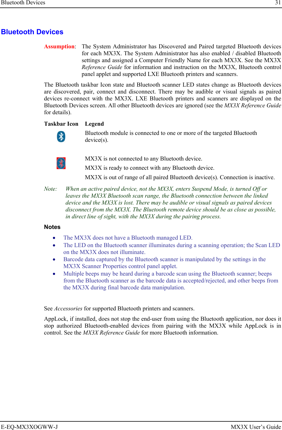
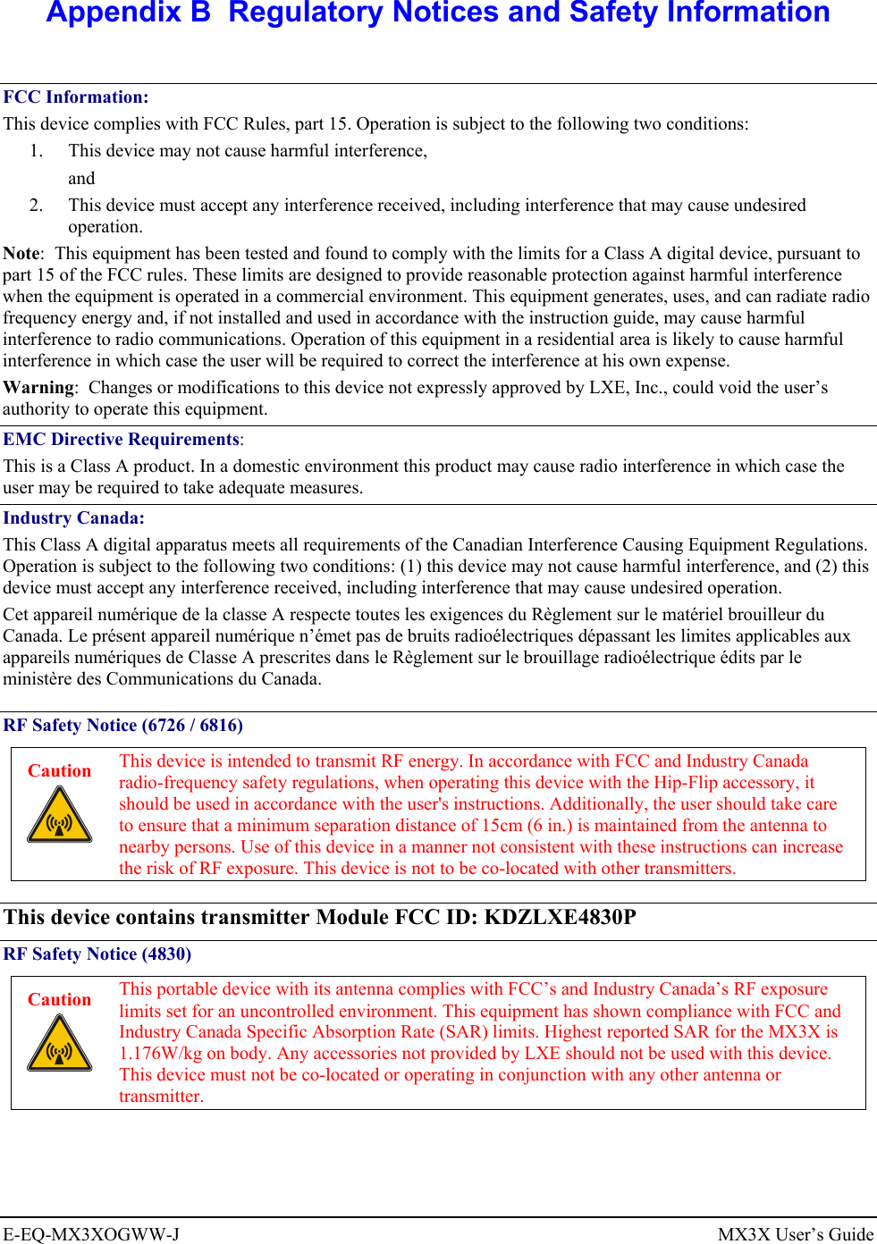
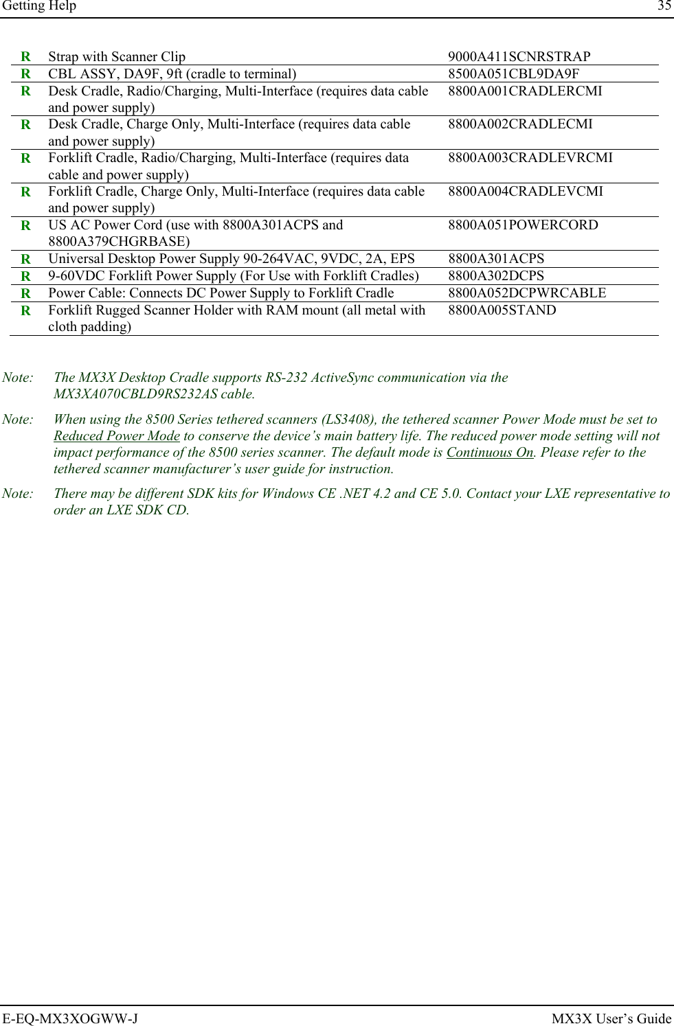
![32 Getting Help MX3X User’s Guide E-EQ-MX3XOGWW-J Getting Help All LXE user guides are now available on one CD and they can also be viewed/downloaded from the LXE ServicePass website. Contact your LXE representative to obtain the LXE Manuals CD. You can also get help from LXE by calling the telephone numbers listed on the LXE Manuals CD, in the file titled Contacting LXE. This information is also available on the LXE website. Explanations of terms and acronyms used in this guide are located in the file titled LXE Technical Glossary on the LXE Manuals CD. Manuals MX3X Reference Guide LXEbook – MX3X User’s Guide (download to MX3X) MX3 Cradle Reference Guide MX3 Multi-Charger Plus User’s Guide CE API Programming Guide RFTerm Reference Guide Integrated Scanner Reference Guide Accessories Note: Items with a Green letter R in the first column are ROHS-compliant. Please contact your LXE representative when ordering ROHS-compliant items as the part number may have changed. Items without the letter R may have received ROHS-compliance after this guide was published. R 1 Cable, USB Host D9F to USB, 6’ (Endcap only) MX3XA069CBL09USBCLNT (for endcaps with a USB-C port only) R 2 Cable, D9F to D9F for ActiveSync only, 6’ (Cradle use only) MX3XA070CBLD9RS232AS / Cradle MX3RA002DESKCRADLE R 3 Cable, USB Client D9F to USB, 6’ (Endcap only) MX3XA071CBLD9USBTYPB (for endcaps with a USB-H port only) R Cable, 12 in., D9F / USB Type A Receptacle MX3XA068CBLD9USBHOST (for endcaps with a USB-H port only) Note: MX3X endcaps with a remote antenna connector (female reverse TNC [RTNC]) do not have an audio port and the MX3X will not have an integrated antenna (normally located inside the device, under the endcap). Tethered Scanners R Scanner, Powerscan SR, 8’ Cbl, WW 8300A326SCNRPWRSR8DA9F Scanner, Powerscan SR, 12’ Cbl, US 8300A327SCNRPWRSR12DA9F](https://usermanual.wiki/Honeywell/LXE4830P.User-Manual-MX3X/User-Guide-886696-Page-40.png)
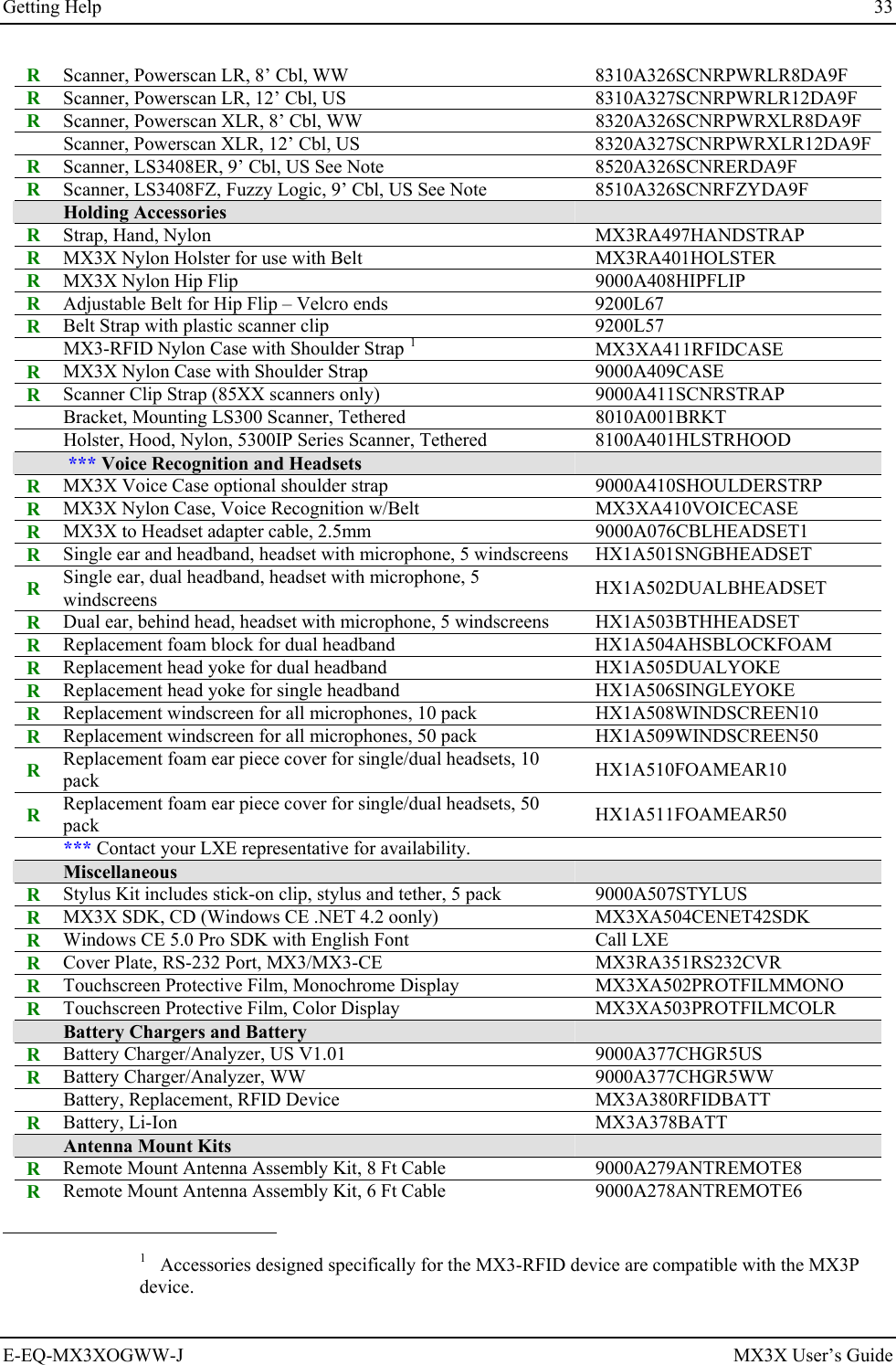

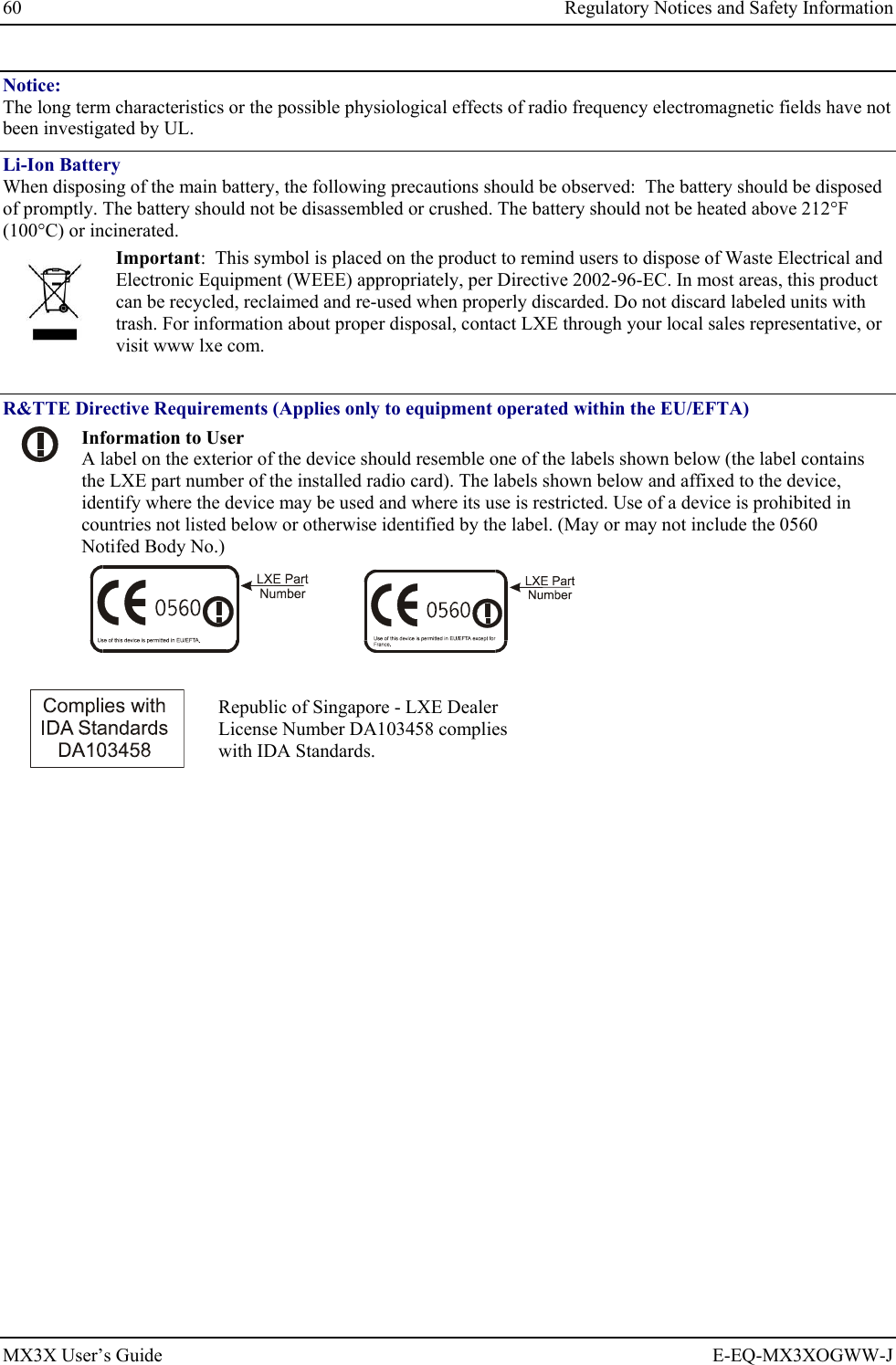
![56 Key Maps MX3X User’s Guide E-EQ-MX3XOGWW-J Press These Keys and Then To get this key 2nd Shift Ctrl Alt CapsLock Press this key X x X Y x Y Z x Z 1 1 2 2 3 3 4 4 5 5 6 6 7 7 8 8 9 9 0 0 DOT DOT < x 0 [ x 1 ] x 2 > x 3 = x 4 { x 5 } x 6 / x 7 - x 8 + x 9 * x I : (colon) x D ; (semicolon) x F ? x L ` x N _ (underscore) x M , (comma) x J ‘ (apostrophe) x H ~ (tilde) x B \ x S | x A](https://usermanual.wiki/Honeywell/LXE4830P.User-Manual-MX3X/User-Guide-886696-Page-64.png)