Honeywell LXE4830P 802.11g COMPACT FLASH MODULE User Manual VX3X User s Guide
Honeywell International, Inc. 802.11g COMPACT FLASH MODULE VX3X User s Guide
Contents
- 1. Manual HX1 rev3
- 2. Manual MX3X rev3
- 3. Manual MX5X rev3
- 4. Manual MX7 rev3
- 5. User Manual HX2
- 6. User Manual MX7
- 7. users manual
- 8. USERS MANUAL
- 9. User Manual MX3X
- 10. User Manual VX3X
- 11. User Manual VX6 part 1
- 12. User Manual VX6 part 2
- 13. User Manual VX7 part 1
- 14. User Manual VX7 part 2
- 15. Users Manual F300
- 16. Users Manual MX9
User Manual VX3X
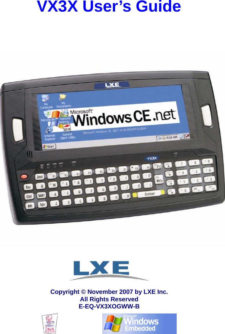

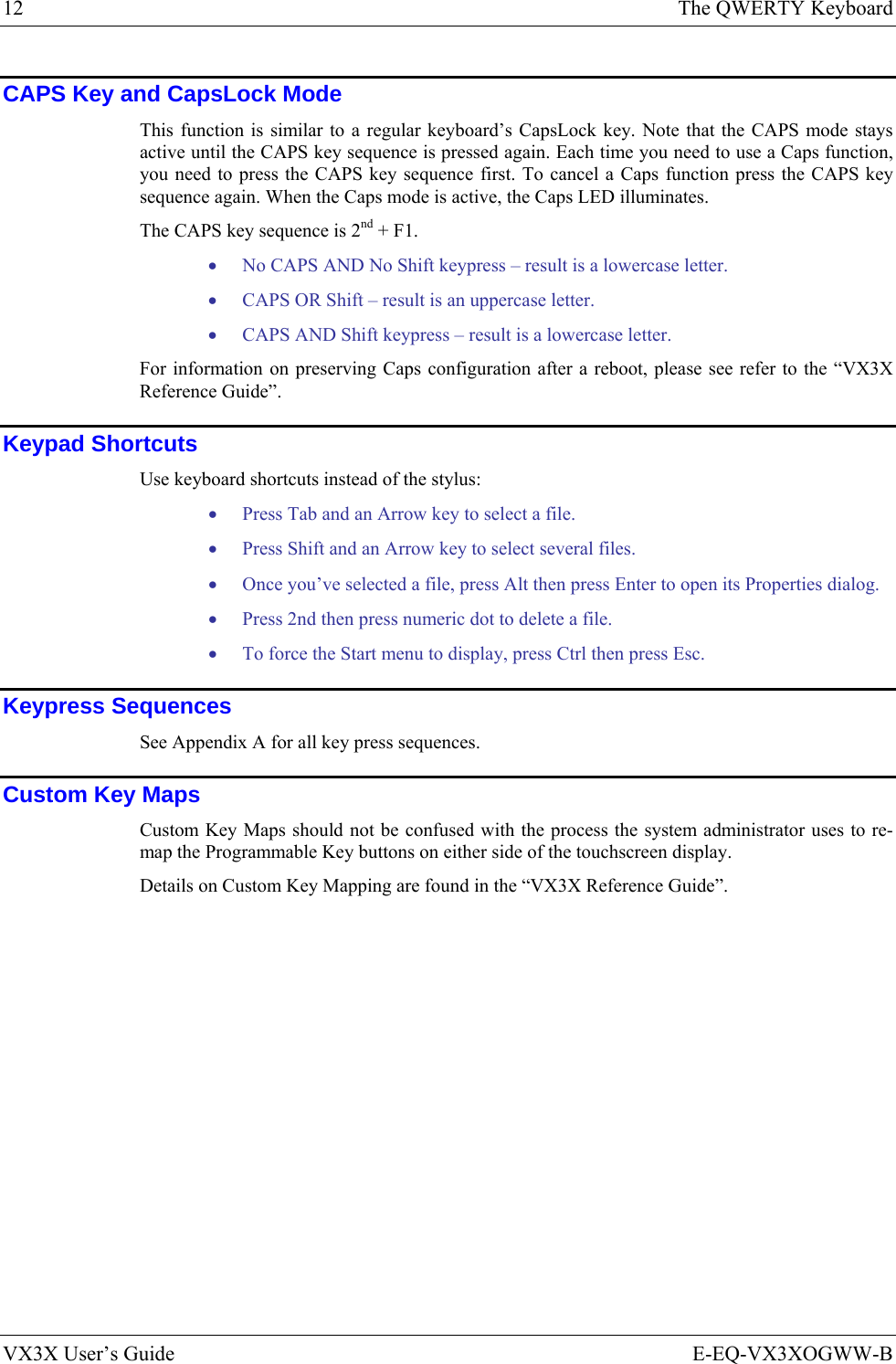
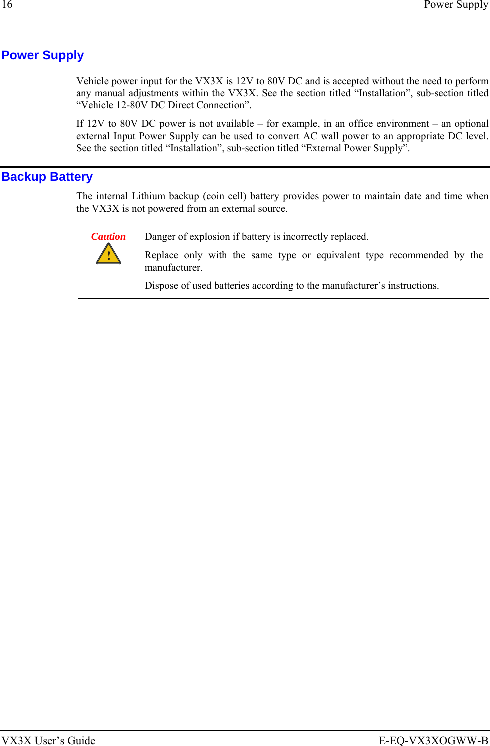
![2 Introduction VX3X User’s Guide E-EQ-VX3XOGWW-B Document Conventions This reference guide uses the following document conventions: ALL CAPS All caps are used to represent disk directories, file names, and application names. Menu|Choice Rather than use the phrase “choose the Save command from the File menu”, this manual uses the convention “choose File|Save”. “Quotes” Indicates the title of a book, chapter or a section within a chapter (for example, “Document Conventions”). < > Indicates a key on the keyboard (for example, <Enter> ). Indicates a reference to other documentation. Differences in operation or commands due to radio type. ATTENTION Keyword that indicates vital or pivotal information to follow. ! Attention symbol that indicates vital or pivotal information to follow. Also, when marked on product, means to refer to the manual or operator’s guide. International fuse replacement symbol. When marked on the product, the label includes fuse ratings in volts (v) and amperes (a) for the product. Note: Keyword that indicates immediately relevant information. Caution ! Keyword that indicates a potentially hazardous situation, which, if not avoided, may result in minor or moderate injury. WARNING ! Keyword that indicates a potentially hazardous situation, which, if not avoided, could result in death or serious injury. DANGER ! Keyword that indicates an imminent hazardous situation, which, if not avoided, will result in death or serious injury. Environmental Specifications Operating Temperature 14°F to 122°F (-10°C to 50°C) [non-condensing] Storage Temperature -22°F to 158°F (-30°C to 70°C) [non-condensing] Operating Humidity 5% to 95% non-condensing at 104°F (40°C) Vibration Based on MIL Std 810D ESD 8 kV air, 4kV contact Shock 75G, 5ms duration, 100 shock impacts Bluetooth Range 32.8 feet (10 meters) Direct line of sight only.](https://usermanual.wiki/Honeywell/LXE4830P.User-Manual-VX3X/User-Guide-886697-Page-10.png)
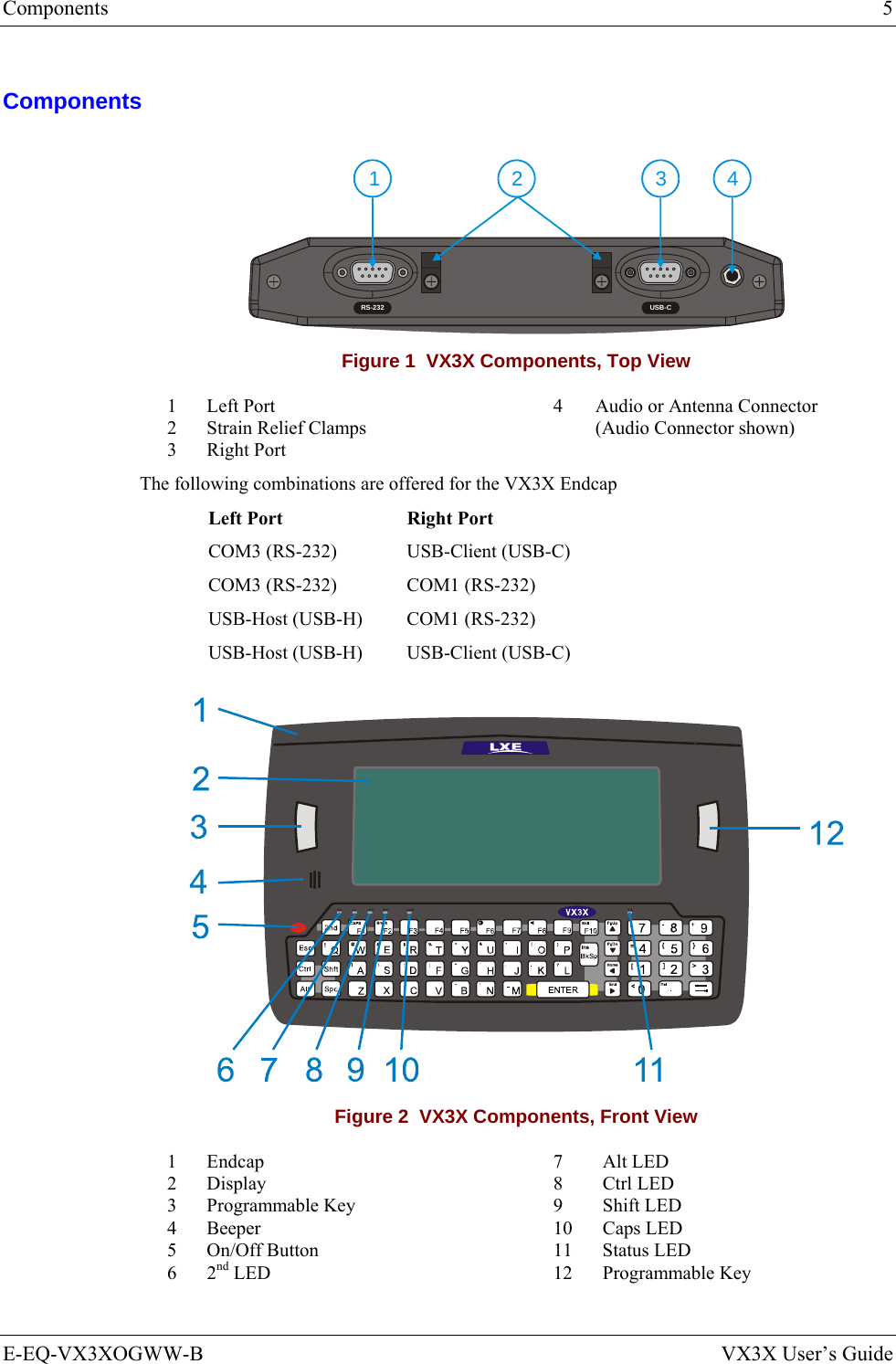
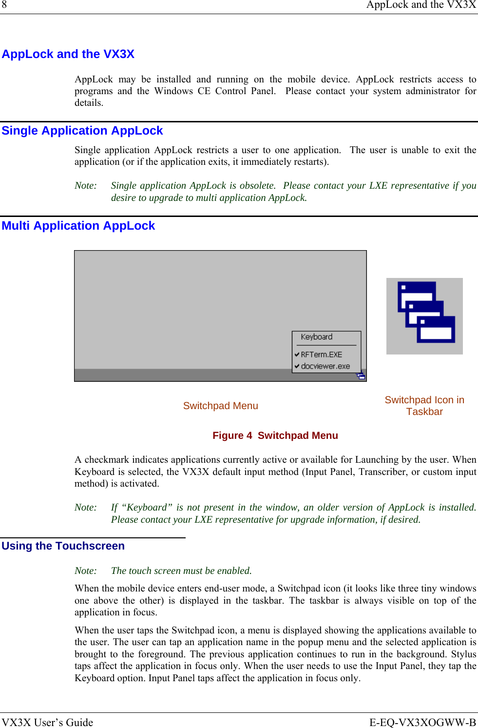
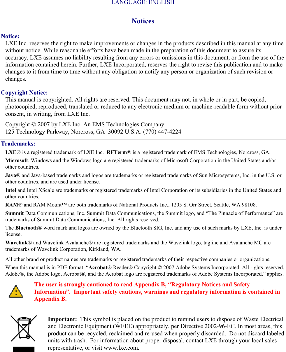
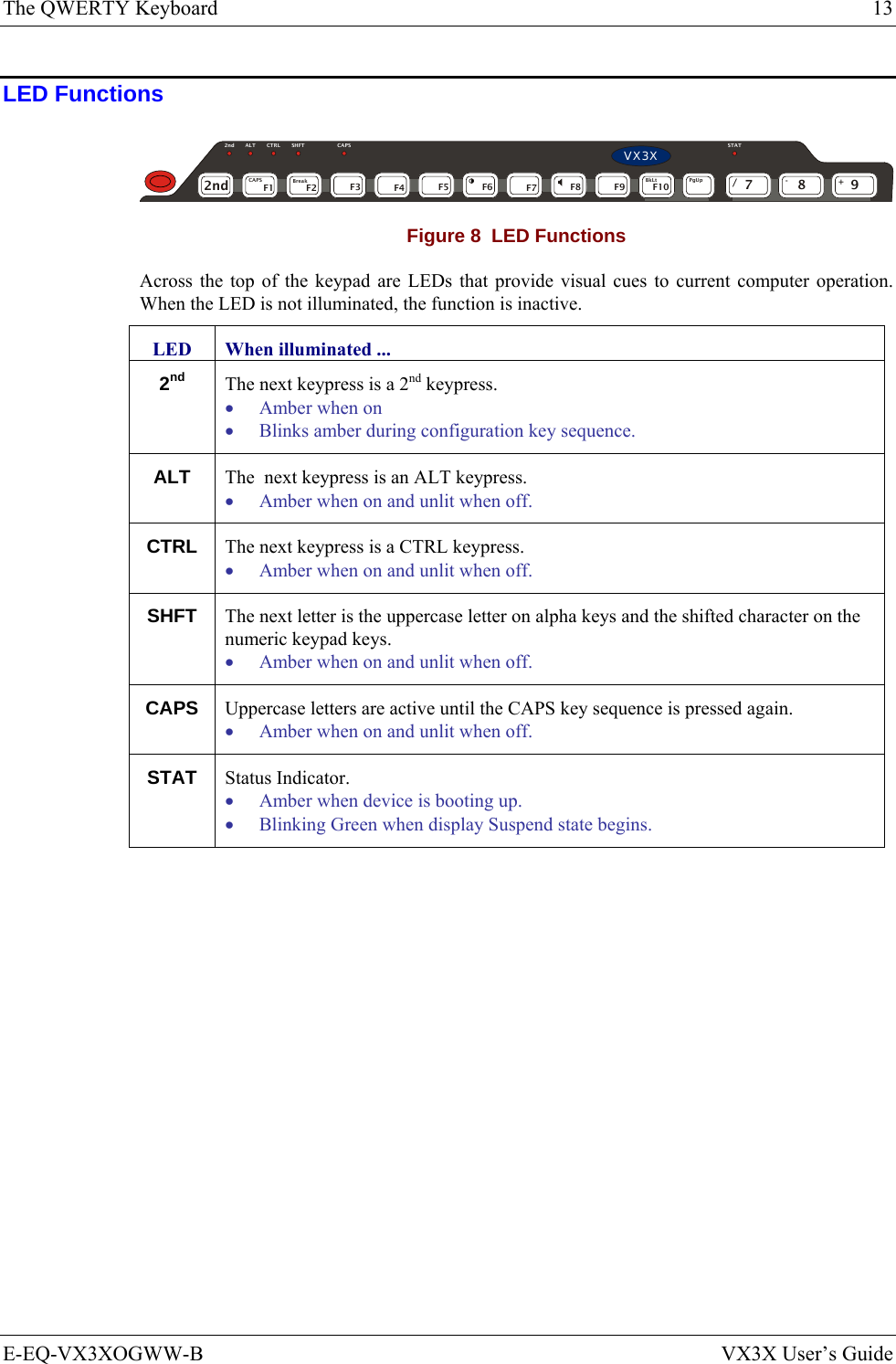
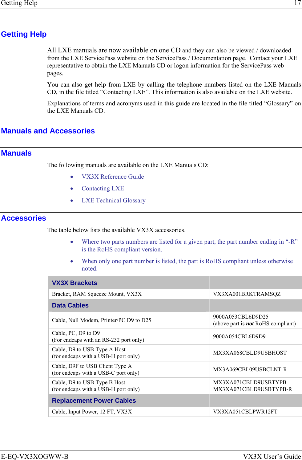
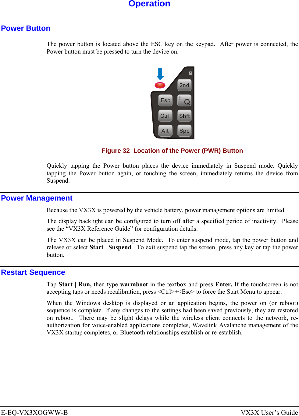
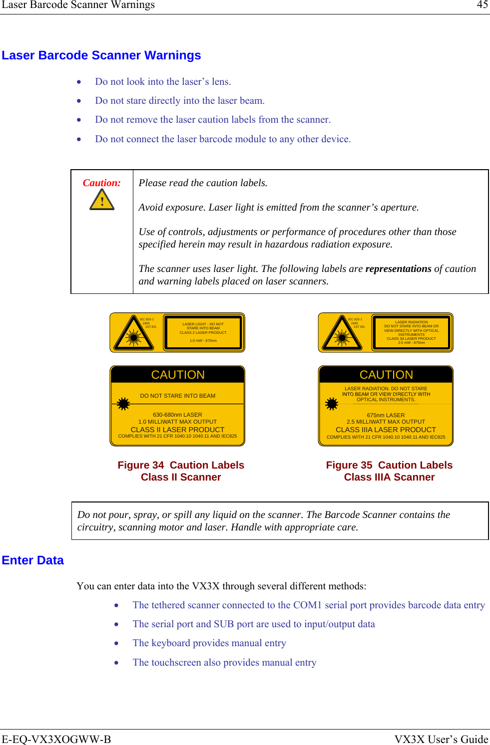
![10 The QWERTY Keyboard VX3X User’s Guide E-EQ-VX3XOGWW-B The QWERTY Keyboard The VX3X has a QWERTY keyboard, available with a standard ANSI overlay, an IBM 3270 overlay or an IBM 5250 overlay. These keyboards have 101 keyboard functions, including a numeric keypad. Please refer to Appendix A, “Key Maps”, for keypress combinations. WERTYUIO PASDFGH JKLZXCVBNMQ!@#$%^&*()|\:; ,.?EscCtrlAltShftSpc2nd~`_EnterPgUpPgDnHomeEnd7894561230/-+={}[]><DelInsBkSpBkLtBreakCAPSF1 F2 F3 F4 F5 F6 F7 F8 F9 F10ٛٛٛٛ2nd ALT CTRL SHFT CAPS STATVX3X Figure 5 QWERTY Keyboard Standard Overlay IBM 3270 Overlay WERTYUIO PASDFGH JKLZXCVBNMQ!@#$%^&*()|\:; ,.?EscCtrlAltShftSpc2nd~`_EnterPgUpPgDnHomeEnd7894561230/-+={}[]><DelInsBkSpBkLtBreakCAPSF1 F2 F3 F4 F5 F6 F7 F8 F9 F10ٛٛٛٛ2nd ALT CTRL SHFT CAPS STATVX3XPA1 PA2 PA3RstDelClrAttn SysReqInsNLE - Inp Figure 6 QWERTY Keyboard with IBM 3270 Overlay IBM 5250 Overlay WERTYUIO PASDFGH JKLZXCVBNMQ!@#$%^&*()|\:; ,.?EscCtrlAltShftSpc2nd~`_EnterPgUpPgDnHomeEnd7894561230/-+={}[]><DelInsBkSpBkLtBreakCAPSF1 F2 F3 F4 F5 F6 F7 F8 F9 F10ٛٛٛٛ2nd ALT CTRL SHFT CAPS STATVX3XDelClrAttn SysReqInsNLE - InpFld +Fld -Dup Figure 7 QWERTY Keyboard with IBM 5250 Overlay Note: Press the <CTRL> + <Enter> keys to initiate the IBM 5250 Field Exit Function.](https://usermanual.wiki/Honeywell/LXE4830P.User-Manual-VX3X/User-Guide-886697-Page-18.png)
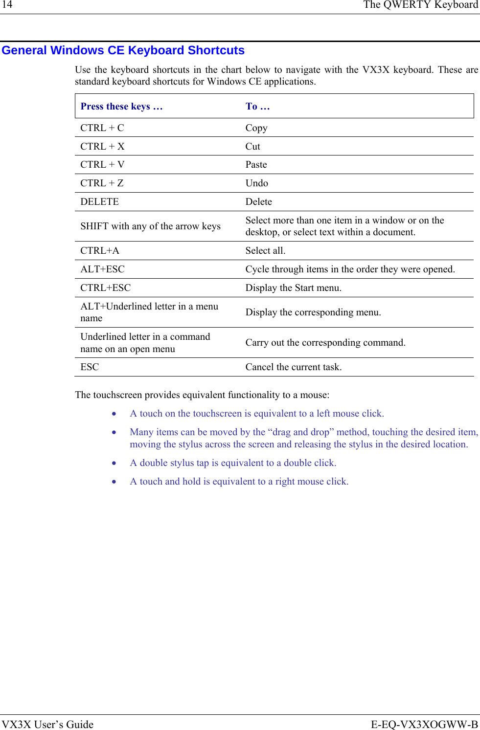
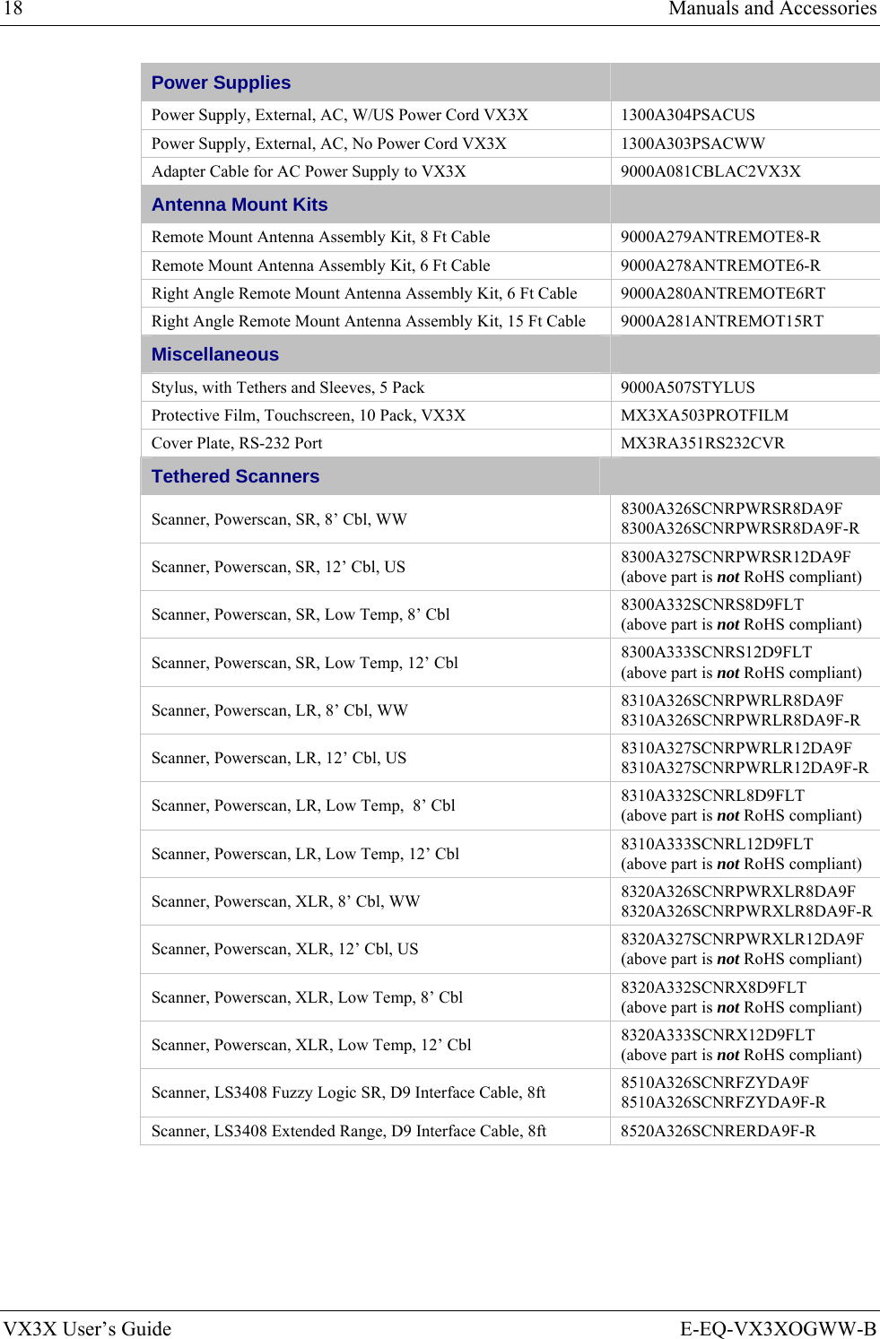
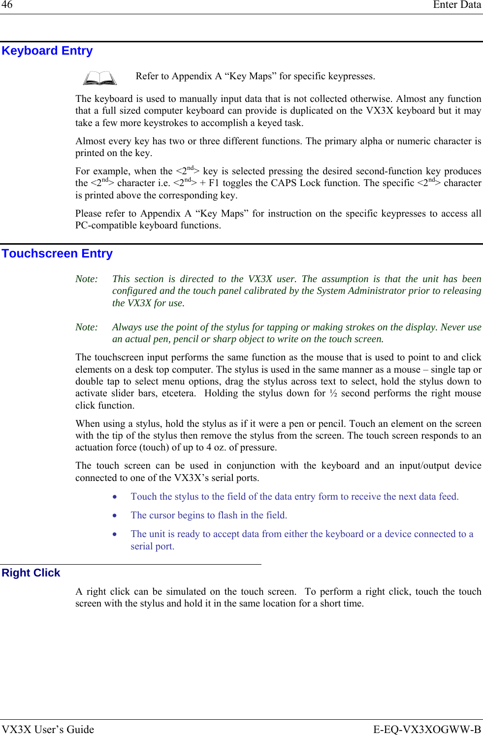
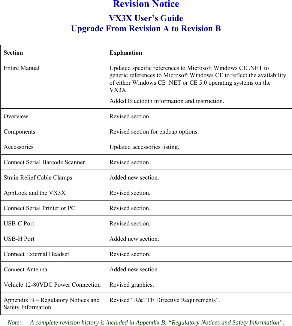
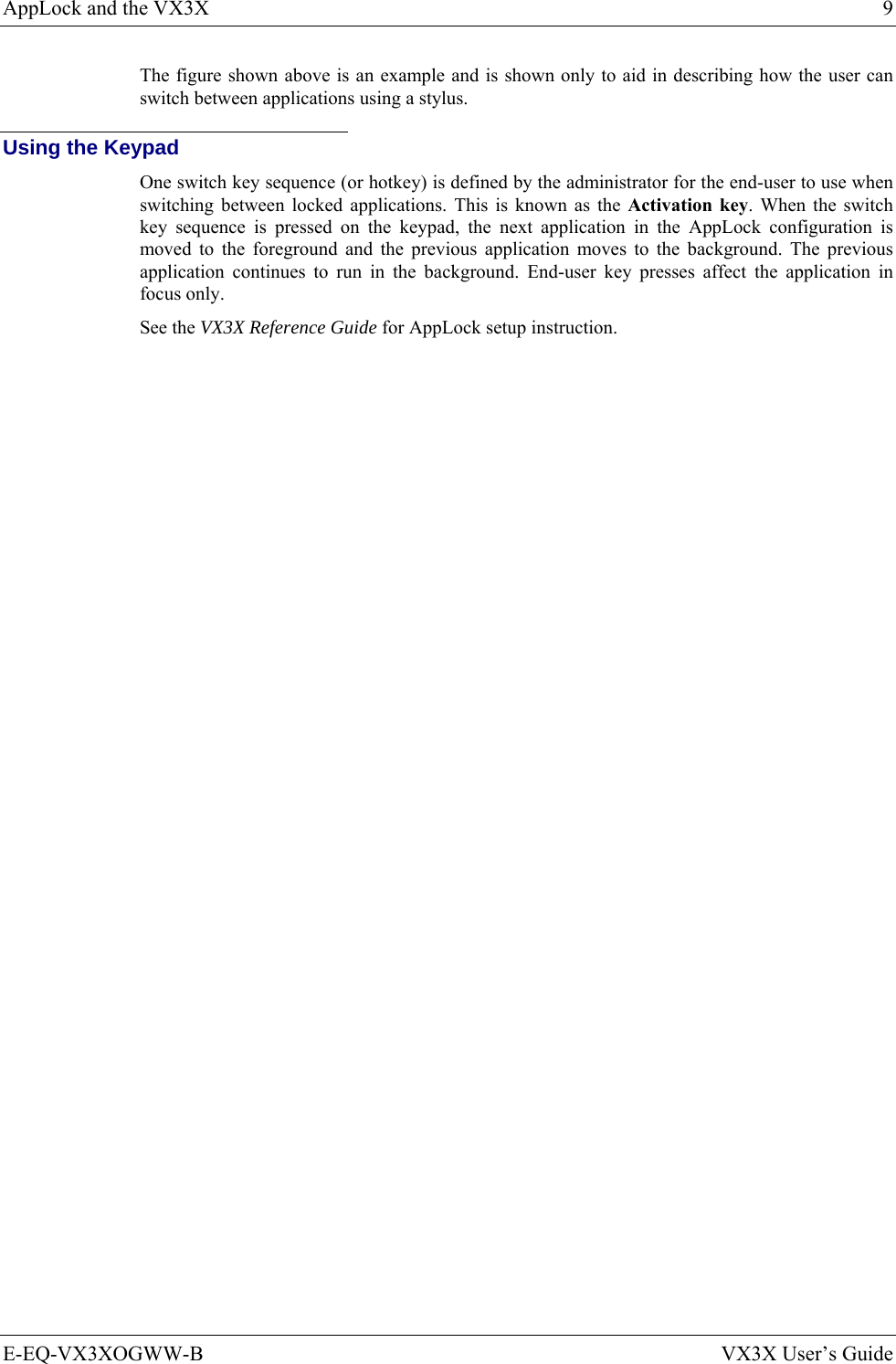
![E-EQ-VX3XOGWW-B VX3X User’s Guide Appendix A Key Maps The VX3X Keypad WERTYUIO PASDFGH JKLZXCVBNMQ!@#$%^&*()|\:; ,.?EscCtrlAltShftSpc2nd~`_EnterPgUpPgDnHomeEnd7894561230/-+={}[]><DelInsBkSpBkLtBreakCAPSF1 F2 F3 F4 F5 F6 F7 F8 F9 F10ٛٛٛٛ2nd ALT CTRL SHFT CAPS STATVX3X Figure 37 VX3X QWERTY Keyboard The key map table that follows lists the commands used for the VX3X. Note that since the VX3X uses a Microsoft Windows CE operating system, no DOS Terminal Emulation keypress sequences are provided. Key Map 101-Key Equivalencies Note: This key mapping is used on VX3X computers that are NOT running LXE’s RFTerm. When using a sequence of keys that includes the 2nd key, press the 2nd key first then the rest of the key sequence. Note: When the computer boots, the default condition of Caps (or CapsLock) is Off. The Caps (or CapsLock) condition can be toggled with a 2nd+F1 key sequence. The CAPS LED is illuminated when CapsLock is On. Press These Keys and Then To get this key 2nd Shift Ctrl Alt CapsLock Press this key Contrast x F6 Volume x F8 Backlight x F10 2nd 2nd Shift Shft Alt Alt Ctrl Ctrl Esc Esc Space Spc Enter Enter](https://usermanual.wiki/Honeywell/LXE4830P.User-Manual-VX3X/User-Guide-886697-Page-59.png)
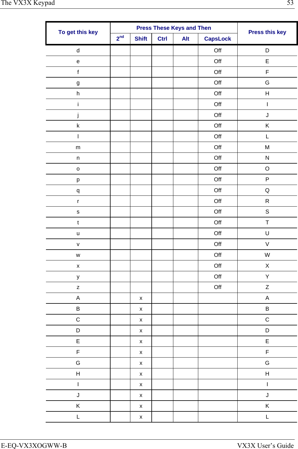
![54 The VX3X Keypad VX3X User’s Guide E-EQ-VX3XOGWW-B Press These Keys and Then To get this key 2nd Shift Ctrl Alt CapsLock Press this key M x M N x N O x O P x P Q x Q R x R S x S T x T U x U V x V W x W X x X Y x Y Z x Z 1 1 2 2 3 3 4 4 5 5 6 6 7 7 8 8 9 9 0 0 DOT DOT < x 0 [ x 1 ] x 2 > x 3 = x 4 { x 5 } x 6 / x 7 - x 8 + x 9](https://usermanual.wiki/Honeywell/LXE4830P.User-Manual-VX3X/User-Guide-886697-Page-62.png)
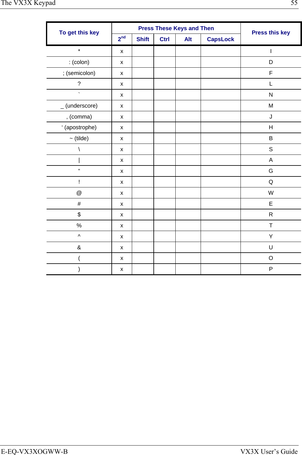
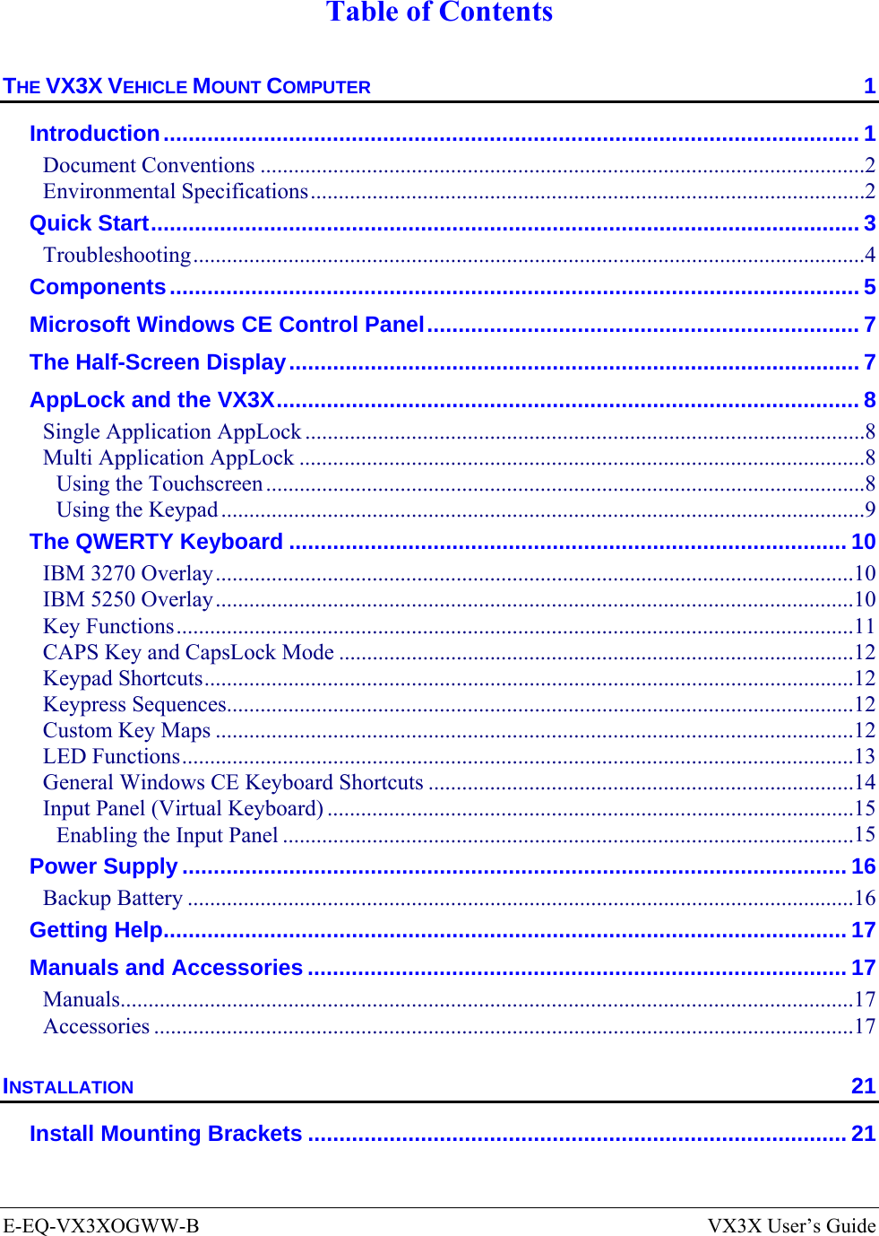
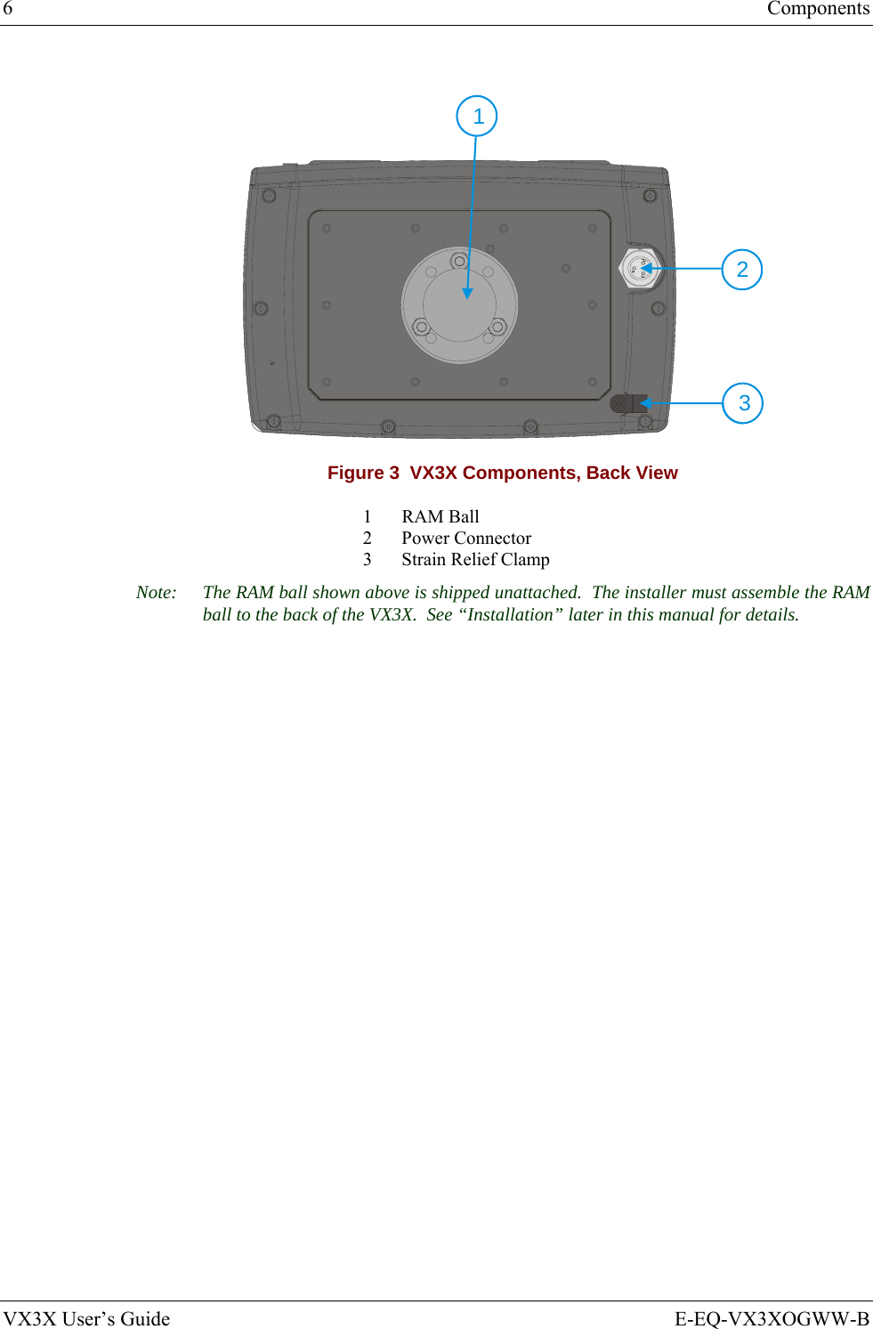
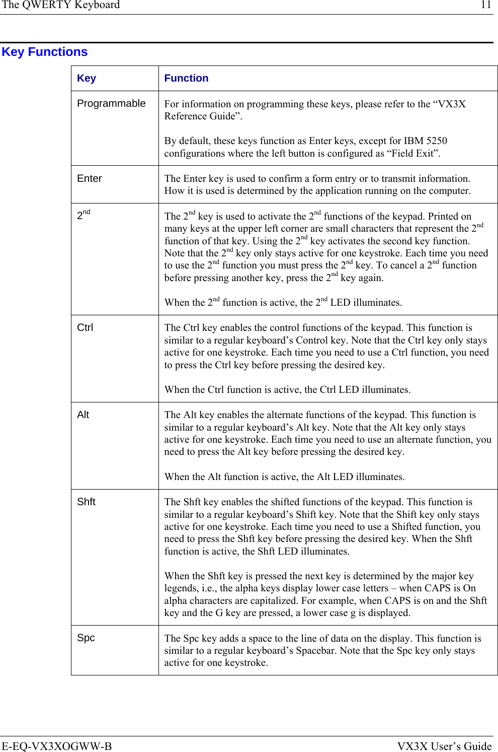
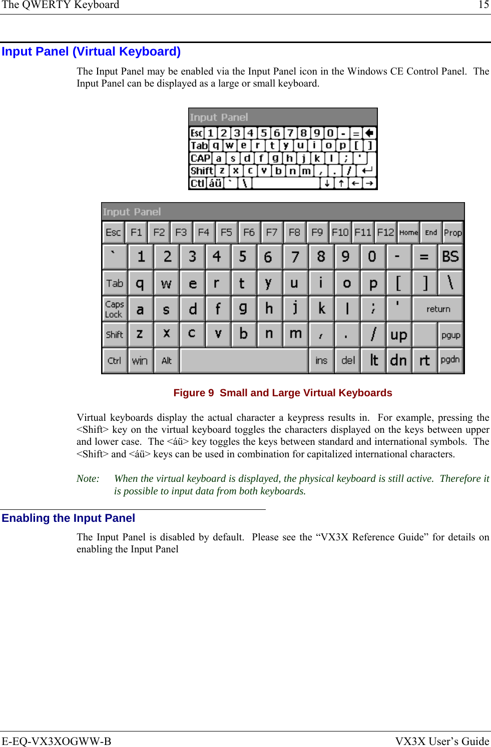
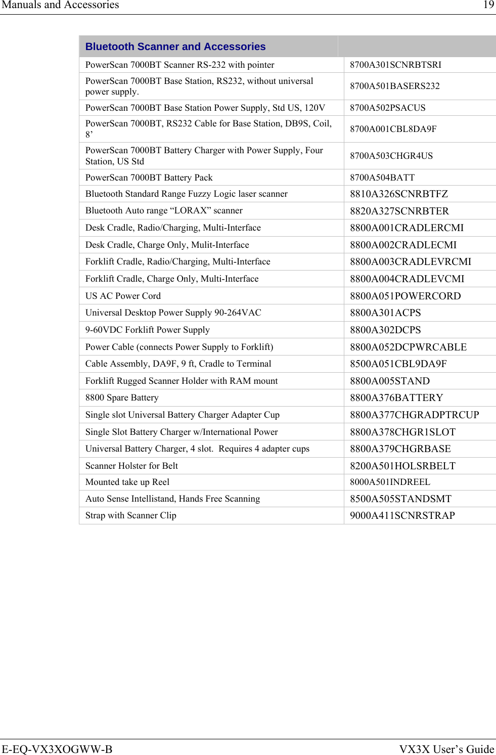
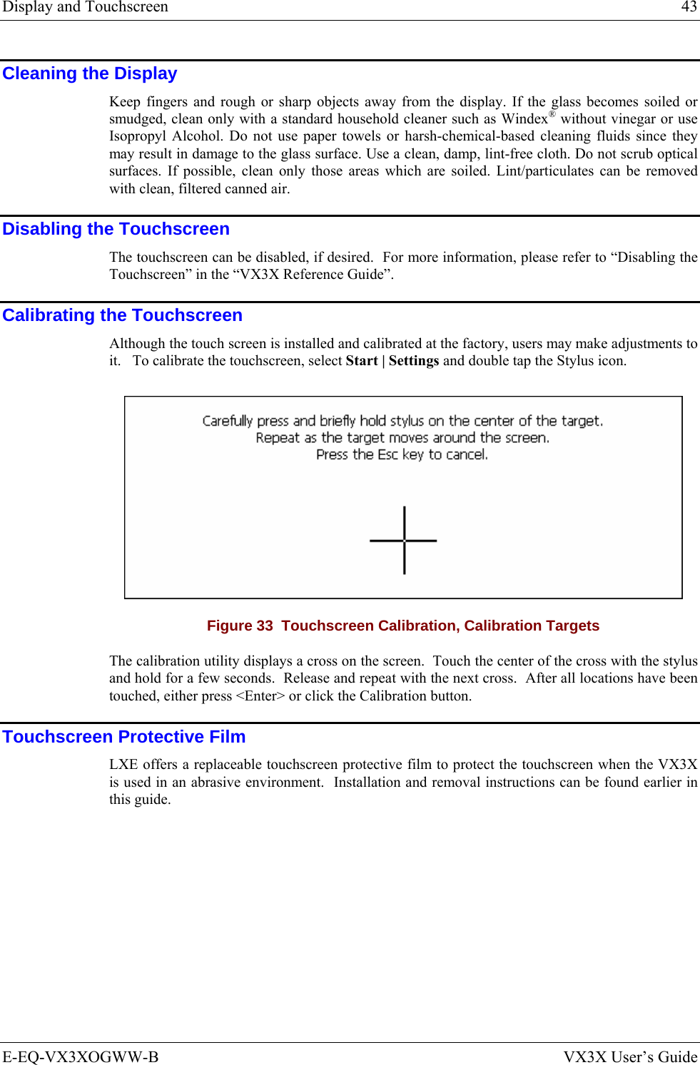
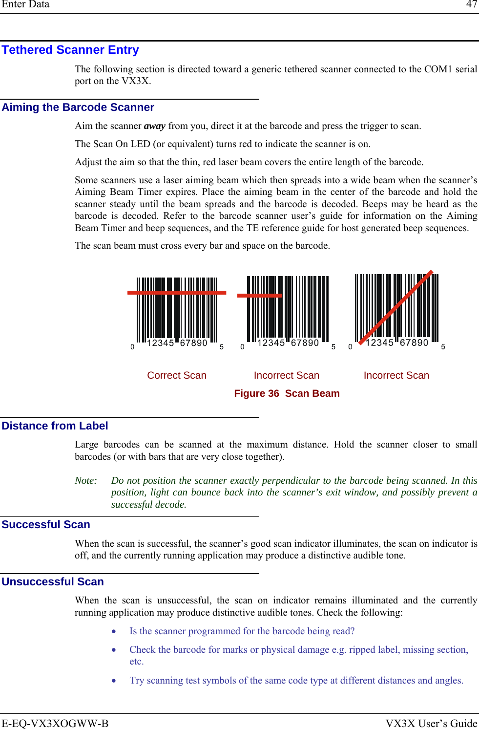
![56 The VX3X Keypad VX3X User’s Guide E-EQ-VX3XOGWW-B IBM 3270 Keypad Overlay WERTYUIO PASDFGH JKLZXCVBNMQ!@#$%^&*()|\:; ,.?EscCtrlAltShftSpc2nd~`_EnterPgUpPgDnHomeEnd7894561230/-+={}[]><DelInsBkSpBkLtBreakCAPSF1 F2 F3 F4 F5 F6 F7 F8 F9 F10ٛٛٛٛ2nd ALT CTRL SHFT CAPS STATVX3XPA1 PA2 PA3RstDelClrAttn SysReqInsNLE - Inp Figure 38 IBM 3270 Specific Keypad The 60-key keypad is available with an IBM 3270 overlay designed to allow the user to enter terminal emulator commands when running LXE’s RFTerm™ program. When running this program please refer to the following reference guide for equivalent keys and keypress sequences: • RFTerm™ Reference Guide IBM 5250 Keypad Overlay WERTYUIO PASDFGH JKLZXCVBNMQ!@#$%^&*()|\:; ,.?EscCtrlAltShftSpc2nd~`_EnterPgUpPgDnHomeEnd7894561230/-+={}[]><DelInsBkSpBkLtBreakCAPSF1 F2 F3 F4 F5 F6 F7 F8 F9 F10ٛٛٛٛ2nd ALT CTRL SHFT CAPS STATVX3XDelClrAttn SysReqInsNLE - InpFld +Fld -Dup Figure 39 IBM 5250 Specific Keypad The 60-key keypad is available with an IBM 5250 overlay designed to allow the user to enter terminal emulator commands when running LXE’s RFTerm™ program. When running this program please refer to the following reference guide for equivalent keys and keypress sequences: • RFTerm™ Reference Guide](https://usermanual.wiki/Honeywell/LXE4830P.User-Manual-VX3X/User-Guide-886697-Page-64.png)