Contents
- 1. TRX7431 User Manual
- 2. Teklogix 9150 Wireless Gateway User Manual
- 3. Teklogix 9150 Wireless Gateway User Manual Declaration of Conformity
- 4. Teklogix 9150 Wireless Gateway User Manual Cautions to Users
- 5. Teklogix 9150 Wireless Gateway User Manual Teklogix Offices
- 6. Teklogix 9150 Wireless Gateway User Manual Table of Contents
- 7. Teklogix 9150 Wireless Gateway User Manual Chapter 1 Introduction
- 8. Teklogix 9150 Wireless Gateway User Manual Chapter 2 Installation Requirements
- 9. Teklogix 9150 Wireless Gateway User Manual Chapter 3 9150 Main Configuration
- 10. Teklogix 9150 Wireless Gateway User Manual Chapter 4 Base Station Configuration
- 11. Teklogix 9150 Wireless Gateway User Manual Chapter 5 Mini Controller Configurati
- 12. Teklogix 9150 Wireless Gateway User Manual Chapter 6 Access Point Configuration
- 13. Teklogix 9150 Wireless Gateway User Manual Chapter 7 Specifications
- 14. Teklogix 9150 Wireless Gateway User Manual Appendix A
- 15. Teklogix 9150 Wireless Gateway User Manual Appendix B
- 16. Teklogix 9150 Wireless Gateway User Manual Index
- 17. Teklogix 9150 Wireless Gateway User Manual Appendix A
- 18. 7035 8255 8260 User Manual
- 19. 9150 User Manual
- 20. response to FCC correspondence 15472
Teklogix 9150 Wireless Gateway User Manual Appendix A

Teklogix 9150 Wireless Gateway User Manual A-1
APPENDIX A
PORT PINOUTS AND CABLE DIAGRAMS
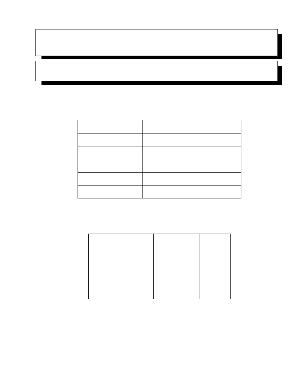
A.1 Console Port
* always pulled high
A.2 RS-232 Plus Port (SLIM Card)
Pin No. Name Function Direction
3 TD Transmit Data Out
2 RD Receive Data In
5 SG Signal Ground –
4* DTR Data Terminal Ready Out
7* RTS Request to Send Out
Pin No. Name Function Direction
1 FG Frame Ground –
2 TD Transmit Data Out
3 RD Receive Data In
7 SG Signal Ground –

Appendix A: Port Pinouts And Cable Diagrams
RS-232/Current Loop Port (SLIM Card)
A-2 Teklogix 9150 Wireless Gateway User Manual
A.3 RS-232/Current Loop Port (SLIM Card)
Pin No. Name Function Direction
1 FG Frame Ground –
2 TD Transmit Data Out
3 RD Receive Data In
4 RTS Request to Send Out
5 CTS Clear to Send In
6 DSR Data Set Ready In
7 SG Signal Ground –
8 DCD Data Carrier Detect In
12 –20 mA Current Loop In
13 –20 mA Current Loop In
14 –20 mA Out Out
19 –Loop Enable Out
20 DTR Data Terminal Ready Out

Teklogix 9150 Wireless Gateway User Manual A-3
Appendix A: Port Pinouts And Cable Diagrams
DA15 Connector Pinout (10Base5 Ethernet)
A.4 DA15 Connector Pinout (10Base5 Ethernet)
Pin No. Function Direction
1 Signal Ground –
2 Collision + In
3 Transmit + Out
4 Signal Ground –
5 Receive + In
6 Signal Ground –
7 No Connection –
8 Signal Ground –
9 Collision - In
10 Transmit - Out
11 Signal Ground –
12 Receive - In
13 +12 Volt Supply Out
14 Signal Ground –
15 No Connection –
Appendix A: Port Pinouts And Cable Diagrams
RJ-45 Connector Pinouts (10Base-T Ethernet)
A-4 Teklogix 9150 Wireless Gateway User Manual
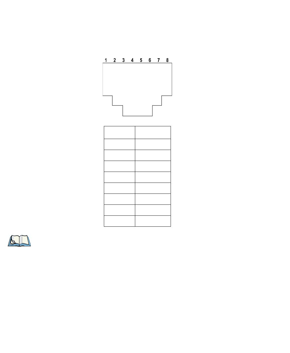
A.5 RJ-45 Connector Pinouts (10Base-T Ethernet)
Note: Usually, a straight-through connection is needed to connect Twisted-Pair
(10Base-T) to the hub.
Contact Signal
1TD+
2TD
–
3RD+
4 Not used
5 Not used
6RD
–
7 Not used
8 Not used

Teklogix 9150 Wireless Gateway User Manual A-5
Appendix A: Port Pinouts And Cable Diagrams
Token Ring Dsub9 Connector
A.6 Token Ring Dsub9 Connector
* This connection supports Shielded Twisted Pair (IBM STP) cable Type 1 or 6.
Pin No. Function Direction
1 Ring Input (A) In
2 Frame Ground –
3 +5 Volt Supply Out
4 Frame Ground –
5 Ring Output (B) Out
6 Ring Input (B) In
7 Frame Ground –
8 Frame Ground –
9 Ring Output (A) Out
Appendix A: Port Pinouts And Cable Diagrams
Serial Cable Descriptions
A-6 Teklogix 9150 Wireless Gateway User Manual
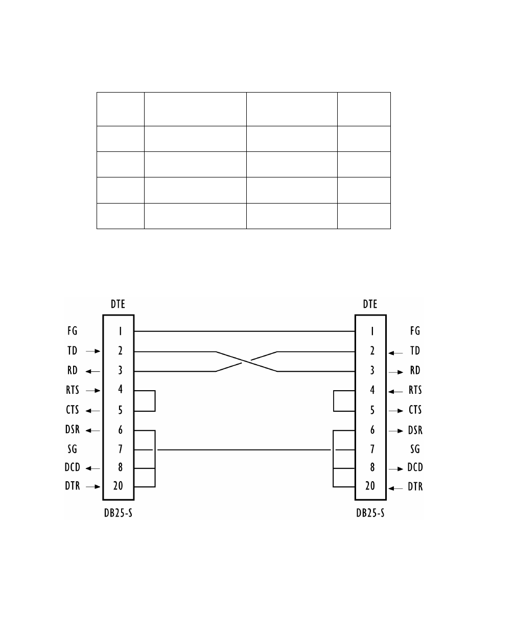
A.7 Serial Cable Descriptions
DTE to DTE Cable No. 16590
Cable No. Function Connection Standard
Length
16590 9400/9300 to 9150 Direct RS-232 15 feet
16598 9400/9300 to 9150 Modem RS-232 8 feet
16599 9400/9300 to 9150 Current Loop 15 feet
19387 9150 to Console Direct 6 feet
Teklogix 9150 Wireless Gateway User Manual A-7
Appendix A: Port Pinouts And Cable Diagrams
Serial Cable Descriptions
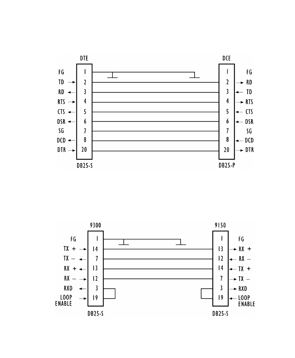
DTE to DCE Cable No. 16598
Current Loop Cable No. 16599
Appendix A: Port Pinouts And Cable Diagrams
Serial Cable Descriptions
A-8 Teklogix 9150 Wireless Gateway User Manual
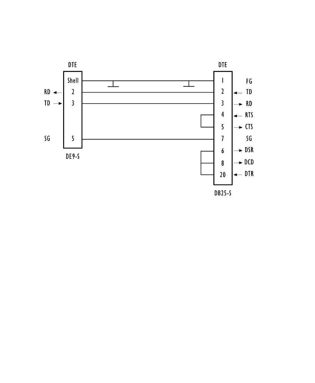
Console Port Cable No. 19387
Teklogix 9150 Wireless Gateway User Manual Appendix A
Teklogix 9150 Wireless Gateway User Manual A-1
APPENDIX A
PORT PINOUTS AND CABLE DIAGRAMS
A.1 Console Port
* always pulled high
A.2 RS-232 Plus Port (SLIM Card)
Pin No. Name Function Direction
3 TD Transmit Data Out
2 RD Receive Data In
5 SG Signal Ground –
4* DTR Data Terminal Ready Out
7* RTS Request to Send Out
Pin No. Name Function Direction
1 FG Frame Ground –
2 TD Transmit Data Out
3 RD Receive Data In
7 SG Signal Ground –

Appendix A: Port Pinouts And Cable Diagrams
RS-232/Current Loop Port (SLIM Card)
A-2 Teklogix 9150 Wireless Gateway User Manual
A.3 RS-232/Current Loop Port (SLIM Card)
Pin No. Name Function Direction
1 FG Frame Ground –
2 TD Transmit Data Out
3 RD Receive Data In
4 RTS Request to Send Out
5 CTS Clear to Send In
6 DSR Data Set Ready In
7 SG Signal Ground –
8 DCD Data Carrier Detect In
12 –20 mA Current Loop In
13 –20 mA Current Loop In
14 –20 mA Out Out
19 –Loop Enable Out
20 DTR Data Terminal Ready Out

Teklogix 9150 Wireless Gateway User Manual A-3
Appendix A: Port Pinouts And Cable Diagrams
DA15 Connector Pinout (10Base5 Ethernet)
A.4 DA15 Connector Pinout (10Base5 Ethernet)
Pin No. Function Direction
1 Signal Ground –
2 Collision + In
3 Transmit + Out
4 Signal Ground –
5 Receive + In
6 Signal Ground –
7 No Connection –
8 Signal Ground –
9 Collision - In
10 Transmit - Out
11 Signal Ground –
12 Receive - In
13 +12 Volt Supply Out
14 Signal Ground –
15 No Connection –

Appendix A: Port Pinouts And Cable Diagrams
RJ-45 Connector Pinouts (10Base-T Ethernet)
A-4 Teklogix 9150 Wireless Gateway User Manual
A.5 RJ-45 Connector Pinouts (10Base-T Ethernet)
Note: Usually, a straight-through connection is needed to connect Twisted-Pair
(10Base-T) to the hub.
Contact Signal
1TD+
2TD
–
3RD+
4 Not used
5 Not used
6RD
–
7 Not used
8 Not used

Teklogix 9150 Wireless Gateway User Manual A-5
Appendix A: Port Pinouts And Cable Diagrams
Token Ring Dsub9 Connector
A.6 Token Ring Dsub9 Connector
* This connection supports Shielded Twisted Pair (IBM STP) cable Type 1 or 6.
Pin No. Function Direction
1 Ring Input (A) In
2 Frame Ground –
3 +5 Volt Supply Out
4 Frame Ground –
5 Ring Output (B) Out
6 Ring Input (B) In
7 Frame Ground –
8 Frame Ground –
9 Ring Output (A) Out

Appendix A: Port Pinouts And Cable Diagrams
Serial Cable Descriptions
A-6 Teklogix 9150 Wireless Gateway User Manual
A.7 Serial Cable Descriptions
DTE to DTE Cable No. 16590
Cable No. Function Connection Standard
Length
16590 9400/9300 to 9150 Direct RS-232 15 feet
16598 9400/9300 to 9150 Modem RS-232 8 feet
16599 9400/9300 to 9150 Current Loop 15 feet
19387 9150 to Console Direct 6 feet

Teklogix 9150 Wireless Gateway User Manual A-7
Appendix A: Port Pinouts And Cable Diagrams
Serial Cable Descriptions
DTE to DCE Cable No. 16598
Current Loop Cable No. 16599

Appendix A: Port Pinouts And Cable Diagrams
Serial Cable Descriptions
A-8 Teklogix 9150 Wireless Gateway User Manual
Console Port Cable No. 19387