Contents
- 1. TRX7431 User Manual
- 2. Teklogix 9150 Wireless Gateway User Manual
- 3. Teklogix 9150 Wireless Gateway User Manual Declaration of Conformity
- 4. Teklogix 9150 Wireless Gateway User Manual Cautions to Users
- 5. Teklogix 9150 Wireless Gateway User Manual Teklogix Offices
- 6. Teklogix 9150 Wireless Gateway User Manual Table of Contents
- 7. Teklogix 9150 Wireless Gateway User Manual Chapter 1 Introduction
- 8. Teklogix 9150 Wireless Gateway User Manual Chapter 2 Installation Requirements
- 9. Teklogix 9150 Wireless Gateway User Manual Chapter 3 9150 Main Configuration
- 10. Teklogix 9150 Wireless Gateway User Manual Chapter 4 Base Station Configuration
- 11. Teklogix 9150 Wireless Gateway User Manual Chapter 5 Mini Controller Configurati
- 12. Teklogix 9150 Wireless Gateway User Manual Chapter 6 Access Point Configuration
- 13. Teklogix 9150 Wireless Gateway User Manual Chapter 7 Specifications
- 14. Teklogix 9150 Wireless Gateway User Manual Appendix A
- 15. Teklogix 9150 Wireless Gateway User Manual Appendix B
- 16. Teklogix 9150 Wireless Gateway User Manual Index
- 17. Teklogix 9150 Wireless Gateway User Manual Appendix A
- 18. 7035 8255 8260 User Manual
- 19. 9150 User Manual
- 20. response to FCC correspondence 15472
Teklogix 9150 Wireless Gateway User Manual Chapter 5 Mini Controller Configurati

Teklogix 9150 Wireless Gateway User Manual 75
MINI-CONTROLLER CONFIGURATION 5
5.1 Overview.............................77
5.2 Hosts...............................80
5.3 Main Host Menu.........................82
5.3.1 General Options...................83
5.3.2 9010 Emulations . . . . . . . . . . . . . . . . . . . 84
5.3.3 3274/Telnet. . . . . . . . . . . . . . . . . . . . . . 84
5.3.3.1 Emulation Options. . . . . . . . . . . . . . . 84
5.3.3.2 Protocol Options. . . . . . . . . . . . . . . . 95
5.3.3.3 Function Key Mappings . . . . . . . . . . . . 98
5.3.4 5250/Telnet. . . . . . . . . . . . . . . . . . . . . . 99
5.3.4.1 Emulation Options. . . . . . . . . . . . . . . 99
5.3.4.2 Protocol Options. . . . . . . . . . . . . . . 110
5.3.4.3 Function Key Mappings . . . . . . . . . . . 112
5.3.5 ANSI/Telnet....................113
5.3.5.1 Emulation Options. . . . . . . . . . . . . . 113
5.3.5.2 Protocol Options. . . . . . . . . . . . . . . 116
5.3.5.3 Function Key Mappings . . . . . . . . . . . 121


Teklogix 9150 Wireless Gateway User Manual 77
Chapter 5: Mini-Controller Configuration
Overview
5.1 Overview
The network controller in a Teklogix system performs a number of important tasks.
One of these tasks is emulation: the translation of data between the protocol of the
host computer and the protocol used by Teklogix terminals.
The data which is sent from a host computer to a terminal to provide its display, and
returned to the host as a result of operations at the terminal, is called a data stream.
Host computers can provide data streams of various types to their terminals.
Teklogix terminals can directly accept only two types of data stream: TESS and
ANSI. TESS (Teklogix Screen Subsystem) is the proprietary data stream used by
Teklogix terminals. ANSI data streams are a standard type of data stream used by
wired ANSI terminals. Other types of data stream provided by the host must be
converted into TESS or ANSI before Teklogix terminals can work with them. This
translation is done by emulation software in a network controller.
The 9150 is equipped with emulation capabilities, allowing it to act as a mini-
controller. When a 9150 is configured as a mini-controller, Teklogix terminals can
emulate an ANSI, 5250 or 3274 terminal via a 9150 rather than through a 9400/9300
Network Controller.
Important: 9150s acting as mini-controllers are designed for small, low-
transaction sites. A 9400/9300 Network Controller is required for
systems that support more than 50 terminals.
Acting as a mini-controller, the 9150 can support up to 32 additional networked base
stations and up to 50 terminals. A 9150 mini-controller can also manage wireless
LAN configurations.
A 9150 configured as a mini-controller can support the following emulations:
• 5250 emulation using TCP/IP over an Ethernet or Token Ring LAN.
• 3274 emulation using TCP/IP over an Ethernet or Token Ring LAN.
• ANSI emulation using TCP/IP over an Ethernet or Token Ring LAN.
Note: The 9150 main parameters should first be set up as described in Chapter 3:
“9150 Main Configuration”.
Chapter 5: Mini-Controller Configuration
Overview
78 Teklogix 9150 Wireless Gateway User Manual
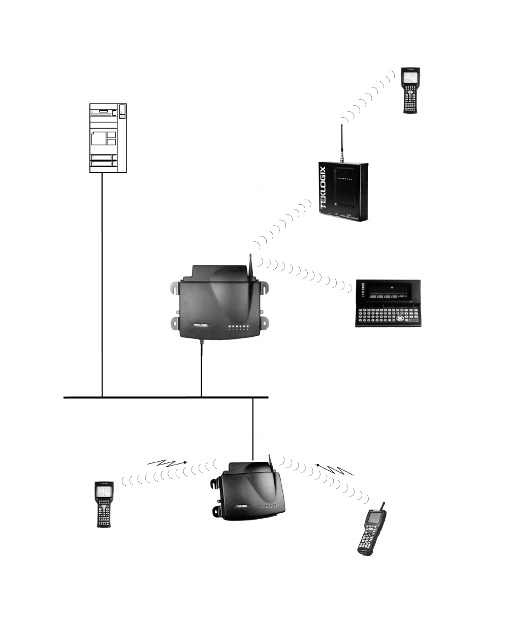
Figure 5.1 9150 Mini-Controller Configuration
Hand-Held
RF Terminal
7035
Hand-Held
RF Terminal
Mini-Controller
9150 Wireless Gateway
Base Station and Access Point
9150 Wireless Gateway
7030
7030 Hand-Held
RF Terminal
802.11 / 2.4 GHz
902 MHz
ETHERNET
TCP/IP
9140
8055 Vehicle-Mount
RF Terminal
Wireless Gateway
HOST
Teklogix 9150 Wireless Gateway User Manual 79
Chapter 5: Mini-Controller Configuration
Overview
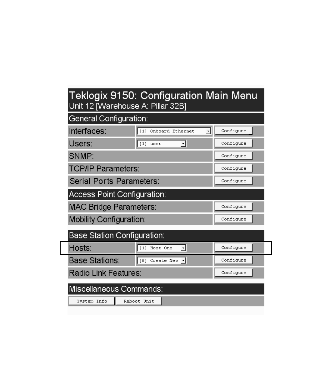
For operation as a mini-controller, the parameters in the Hosts pages under Base
Station Configuration should be set appropriately. The Hosts options are found on
the Configuration Main Menu page. For information on configuring radio protocol
parameters, please refer to “Radio Link Features” on page 72.
Chapter 5: Mini-Controller Configuration
Hosts
80 Teklogix 9150 Wireless Gateway User Manual
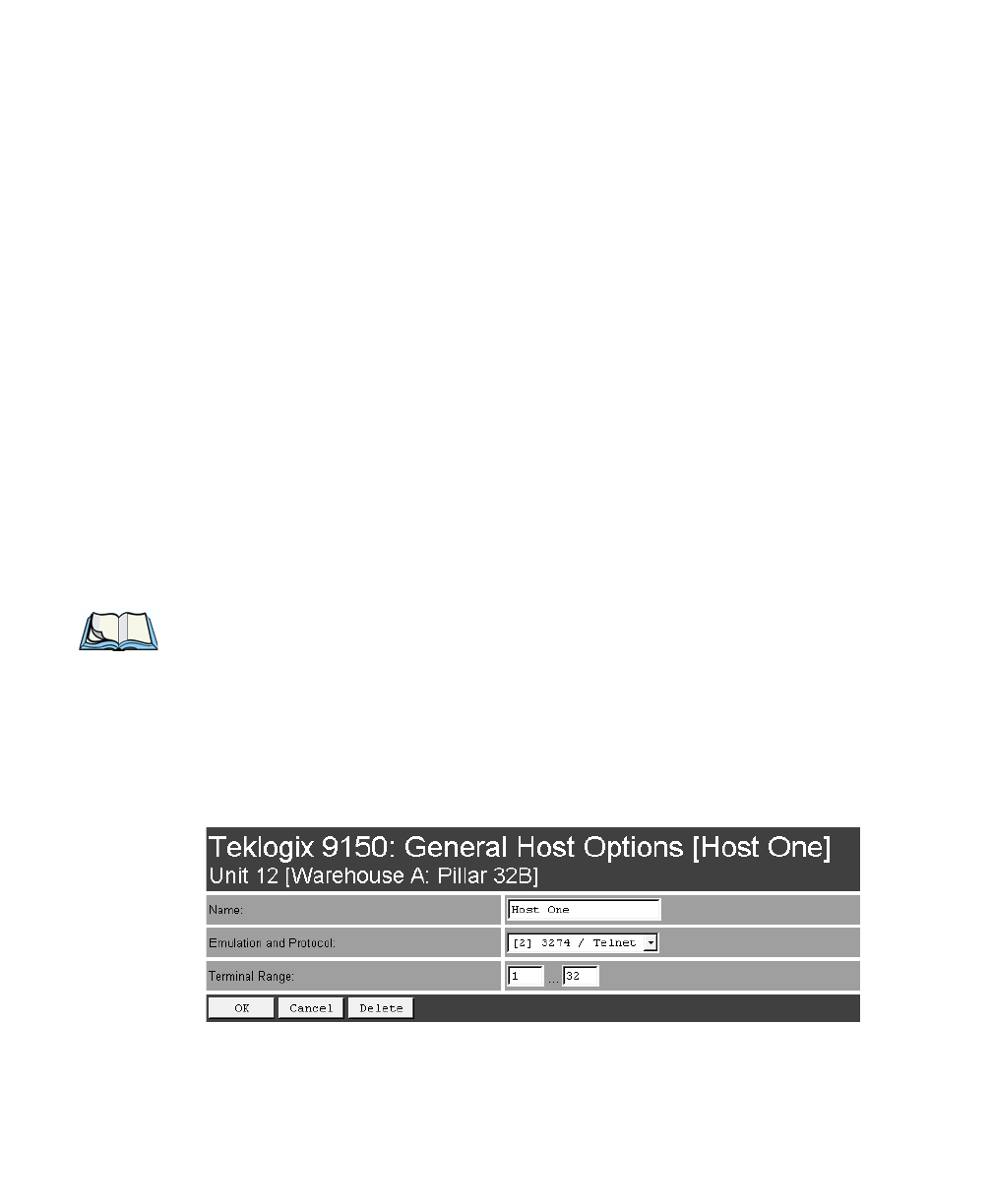
5.2 Hosts
The drop-down menu in this option shows the host names present on the system. Up
to six hosts can be supported. A “host” must be configured for each host that com-
municates with the 9150 mini-controller. Opening the Configure dialog box for a
selected host lists the parameters that can be modified or deleted for that host. New
hosts can be added by selecting “[#] Create New” in the drop-down menu before
entering the Configure dialog box.
Name
This parameter indicates the assigned host name. The host name also appears on the
RF terminal when switching between hosts in a multiple-host environment.
Enabled
The Enabled option must be turned on ( √ ) for terminals to communicate with
this host.
Emulation and Protocol
This drop-down menu provides a list of host emulations and communication proto-
cols supported by the 9150. Working with Teklogix terminals and base stations, the
9150 can emulate IBM 3278-2, 5251-11, and 5555-B01 terminals, as well as
ANSI terminals.
Protocols are the methods by which terminals communicate with host computers
over various physical media such as Ethernet, Token Ring, and serial connections, as
well as radio-link connections. The 9150 supports the TCP/IP protocol.

Teklogix 9150 Wireless Gateway User Manual 81
Chapter 5: Mini-Controller Configuration
Hosts
The supported emulations with their respective protocols are:
• 9010/ TCP/IP or Serial (See page 84 for Configuration Parameters).
• 3274/Telnet (See pages 84 to 98 for Configuration Parameters).
• 5250/Telnet (See pages 99 to 112 for Configuration Parameters).
• ANSI/Telnet (See pages 113 to 121 for Configuration Parameters).
When the 9150 acts as a base station, it uses the 9010 emulation (a proprietary asyn-
chronous protocol developed by Teklogix) to communicate with a 9300 Network
Controller or a host using a Teklogix Software Development Kit (TSDK). For
detailed information on configuring the 9150 as a base station, please refer to
Chapter 4: “Base Station Configuration”.
When the 9150 acts as a mini-controller, it uses the 3274 and 5250 emulation
protocols to communicate with IBM hosts, or the ANSI emulation protocol to com-
municate with ANSI terminals.
Terminal Range
The values entered in this parameter designate the first and last terminals in the
range of terminals that will communicate with the host. These terminal numbers are
mapped to this particular host. Terminal numbers may range from 1 to 50.
Chapter 5: Mini-Controller Configuration
Main Host Menu
82 Teklogix 9150 Wireless Gateway User Manual
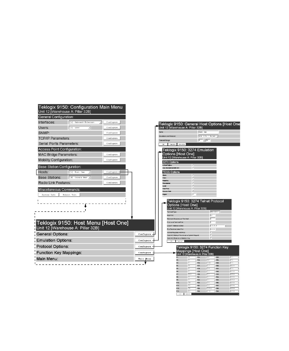
5.3 Main Host Menu
When you choose an existing host name from the Hosts listbox and then select the
Configure button, the 9150 displays the Host Menu. The Host Menu presents the
options for four sub-menus: General Host Options, Emulation Options, Protocol
Options, and Function Key Mappings. There is also a Main Menu button. When
you select this button, the 9150 displays the Configuration Main Menu page
(see page 79 for an enlarged illustration).
Figure 5.2 Overview Of Host Menus
Teklogix 9150 Wireless Gateway User Manual 83
Chapter 5: Mini-Controller Configuration
General Options
As illustrated in Figure 5.2 on page 82, the four configuration sub-menus display the
following options:
“General Options”
When you select this sub-menu, the 9150 displays the General Options page for
the host.
“Emulation Options”
When you select this sub-menu, the 9150 displays the Emulation Options page
for the host. This page may vary depending on the type of emulation and proto-
col selected for the host.
“Protocol Options”
When you select this sub-menu, the 9150 displays the Protocol Options page
for the host. This page may vary depending on the type of emulation and proto-
col selected for the host.
“Function Key Mappings”
When you select this sub-menu, the 9150 displays the Function Key Mappings
page for the host. This page may vary depending on the type of emulation and
protocol selected for the host.
Note: The Function Key Mappings parameters are not applicable to either of
the 9010 emulations; the Protocol Options parameters do not apply to the
9010/TCP/IP emulation.
5.3.1 General Options
In this page, you can select general options for this host connection. The host con-
nection may also be deleted.

Chapter 5: Mini-Controller Configuration
9010 Emulations
Emulation Options
84 Teklogix 9150 Wireless Gateway User Manual
Name
This parameter allows you to enter a name for the new host.
Emulation and Protocol
This parameter allows you to select the emulation and protocol to be used for the
connection to this host. Available combinations of emulation and protocol are:
3274/Telnet, 5250/Telnet, ANSI/Telnet.
Terminal Range
This parameter allows you to specify the range of terminals which will communi-
cate with this host. The left-hand textbox contains the lowest terminal number which
is allowed to communicate with the host; the right-hand textbox contains the highest
terminal number. Terminal numbers may range from 1 to 50.
5.3.2 9010 Emulations
When the 9150 acts as a base station, it uses the 9010 protocol (a proprietary asyn-
chronous protocol developed by Teklogix) to communicate with a 9400 or 9300
Network Controller, or a host using a Teklogix Software Development Kit (TSDK).
For detailed information on configuring the 9150 as a base station, please refer to
Chapter 4: “Base Station Configuration”.
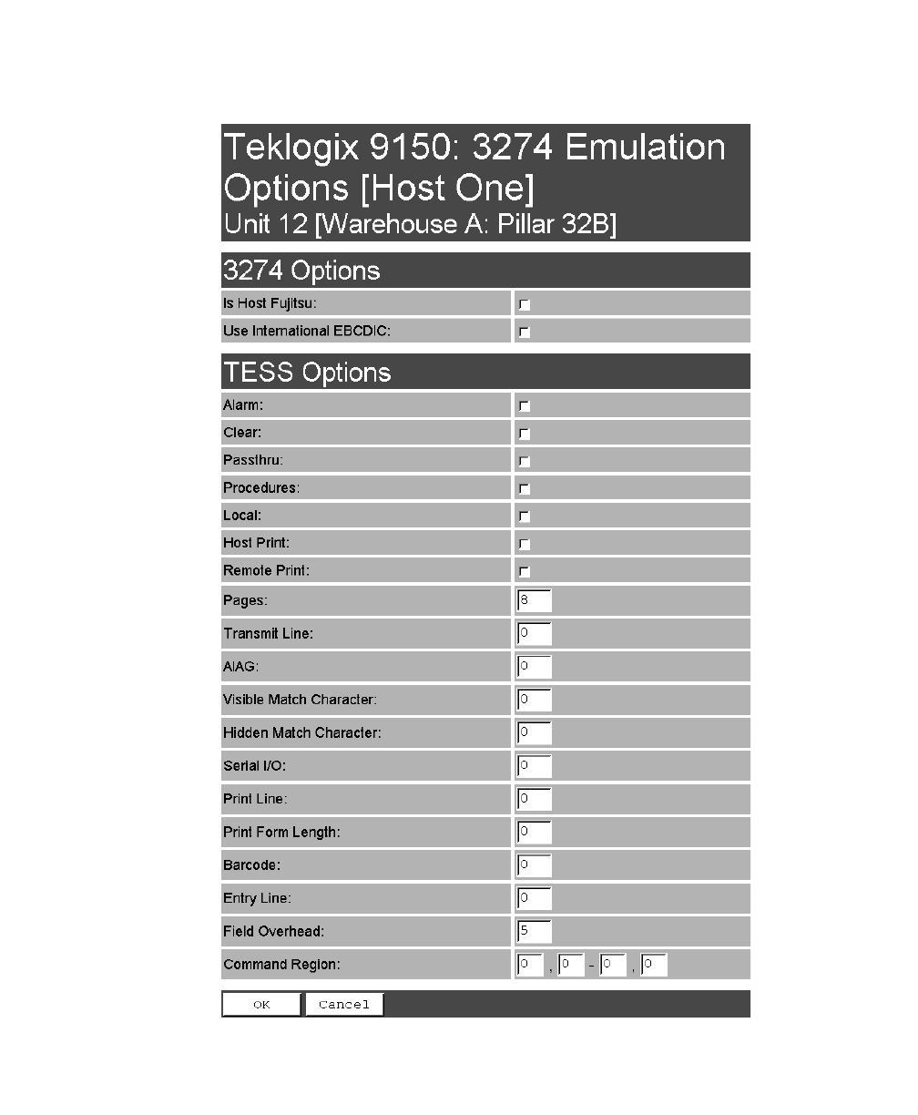
5.3.3 3274/Telnet
5.3.3.1 Emulation Options
The 9150 mini-controller displays this version of the Emulation Options page
after you have selected the 3274/Telnet emulation/protocol combination for this host
connection.
With IBM 3274, or IBM 5250 emulation, the 9150 mini-controller converts the
application data stream from the host to TESS (Teklogix Screen Subsystem)
commands. Some of the parameters in this page govern the conversion of the host
screens to TESS.
Teklogix 9150 Wireless Gateway User Manual 85
Chapter 5: Mini-Controller Configuration
3274/Telnet
Emulation Options

Chapter 5: Mini-Controller Configuration
3274/Telnet
Emulation Options
86 Teklogix 9150 Wireless Gateway User Manual
Is Host Fujitsu
If this parameter is enabled, the 9150 mini-controller sends its data in Fujitsu
format. Enabling this parameter causes the standard IBM formatting codes (for
start of field, setting buffers, etc.) to be replaced by the codes used by Fujitsu
host computers.
Use International EBCDIC
If this parameter is enabled, the 9150 mini-controller uses the International
EBCDIC character set, swapping the positions of the ! and ] characters.
Alarm
When this parameter is enabled, terminals beep when the word “ALARM” appears
on the application screen in the location specified by the Command Region parame-
ter (see page 95). The word “ALARM” should be a display-only field.
Note: The Command Region parameter must be enabled for this
parameter to work.
Clear
If this parameter is enabled, the 9150 mini-controller creates an empty entry field
for an entry field that is filled with spaces.
Some host applications rely on the video attributes of displayed characters to high-
light fields, particularly entry fields. For example, the application screen may define
all entry fields with reverse video and fill the field with spaces. This is effective on
terminals that support reverse video, but on terminals that do not, it can make the
field invisible since it is made up entirely of spaces.
By default, all empty entry fields displayed at the Teklogix terminal are highlighted
by the “entry character” chosen in the terminal’s configuration (not all Teklogix ter-
minals support video attributes).
Note: This operation is only performed on screens received from the host. Data
sent to the host remains unaffected.
Passthru
If this parameter is enabled, the 9150 allows the host to send data directly to the RF
terminal’s serial port. This is most commonly used for printing.

Teklogix 9150 Wireless Gateway User Manual 87
Chapter 5: Mini-Controller Configuration
3274/Telnet
Emulation Options
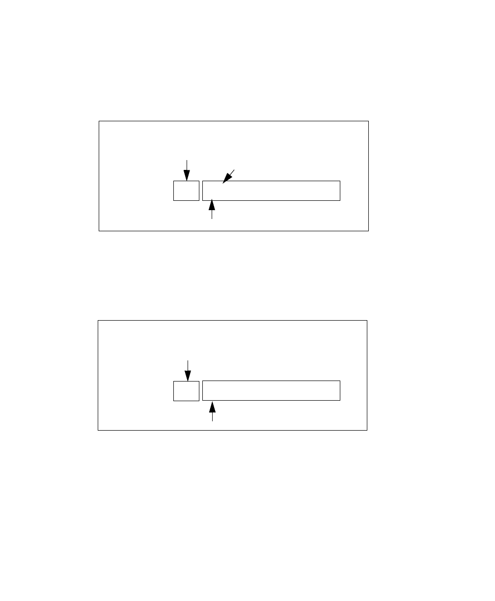
Preparing Host Screens for Pass-Through
On the screen to be sent through the terminal serial port, the word PASSTHRU (in
capital letters) must appear on the first line, starting on the second column. The
actual data to be sent to the terminal may start anywhere below the first line.
With 5250 or 3274 emulations, attributes occupy a position in the screen buffer. An
attribute placed between column 2 and the end of the word “PASSTHRU” will
‘push’ all following characters one position to the right. Therefore, any required
attributes should occupy column 1 of the first line (just preceding the word
“PASSTHRU”).
Example:
where @ is an attribute.
When the 9150 is finished sending the data to the terminal’s printer, it will send an
ENTER key to the host. The host must wait for the ENTER key before sending any
more screens (including other PASSTHRU screens) to this terminal.
Note: Refer to the Terminals User Manual for information about setting
parameters on the terminal for pass-through.
Procedures
If this parameter is enabled, the host may send TESS procedures through the 9150
to the terminals. A TESS procedure is a group of TESS commands that can be exe-
cuted by the TESS execute procedure command.
Local
If this parameter is enabled, the 9150 allows the host to provide pages to be loaded
as local TESS procedures in the terminals.
The local procedures are selected from a menu at the terminal. The terminals can
perform these procedures when they are offline. Later when the terminals are online,
they send the results of these functions to the host.
column: 1 2 3 4 5 6 7 8 9
line 1: @ P A S S T H R U @
line 2: @ P A R T : 1 2 3 4 5

Chapter 5: Mini-Controller Configuration
3274/Telnet
Emulation Options
88 Teklogix 9150 Wireless Gateway User Manual
Note: The Procedures parameter must also be enabled for Local to work.
Host Print
When this parameter is enabled, the host can send extra data to the terminal’s
screens, and instruct the terminal to print it. This is in contrast to the Local Print fea-
ture, where the terminal makes the initial print request.
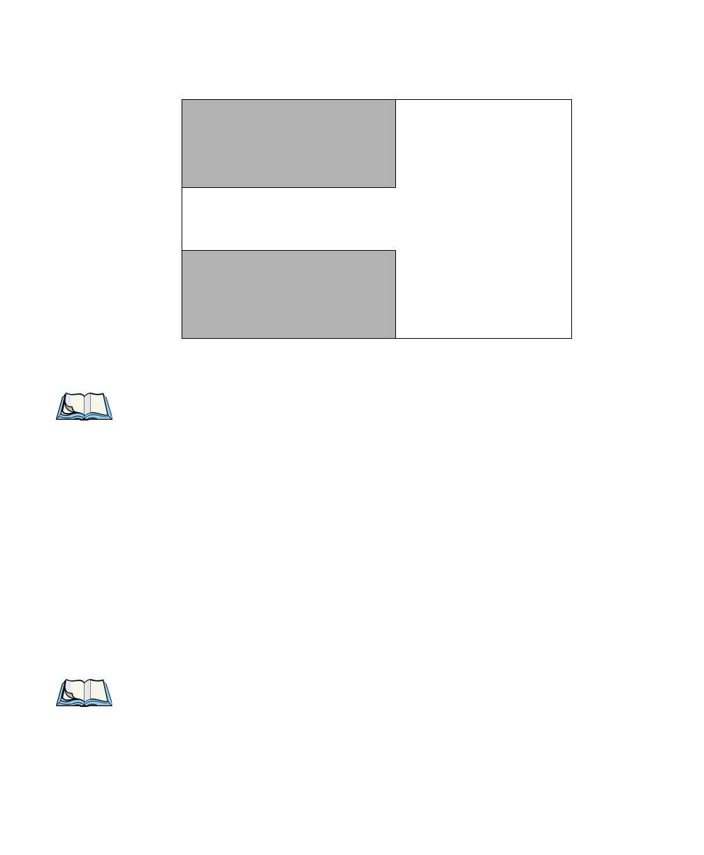
The text that is passed to the printer is formatted into the 24 x 80 application screen.
If the host can initiate the print operation, the text is printed. The 9150 identifies the
additional text as a print page by the presence of the word “PRINT” (in capital let-
ters) beginning in the 2nd column of line 13 on the 24 x 80 screen. The word
“PRINT” should be defined as display-only text.
The print page is positioned below the terminal’s display page (see the following
figure). The size of the print page is always the same as the terminal’s display page
(assuming that in the terminal’s configuration, the page length is less than 12 lines).
When Host Print is enabled, the 9150 passes the print page to the terminal after
receiving the application screen from the host.
Figure 5.3 Application Screen With Print Page
1
2
3
4
5
6
7
8
9
10
11
12
13
14
15
16
17
18
19
20
21
22
23
24
Display Page (8 x 40)
Print Page (8 x 40)
PRINT

Teklogix 9150 Wireless Gateway User Manual 89
Chapter 5: Mini-Controller Configuration
3274/Telnet
Emulation Options
Notes:
1. Unlike the Passthru option, when using Host Print no escape
commands can be sent to the printer.
2. Support for printing must be enabled at the terminal in its
Printer command under the TESS Features menu; refer to the
7030/8055/8060 Terminals User Manual for more information.
Remote Print
When this parameter is enabled, the 9150 sends the print page to a terminal when-
ever the terminal requests it (by sending the “F17” function key from the terminal,
or the “PRINT” key on older terminals). The 9150 sends the function response back
to the host.
This is in contrast to Host Print, where the host makes the initial print request.
Note: Support for printing must be enabled at the terminal. Refer to the
Terminals User Manual or the Parameter Guide for more information.
Pages
This parameter determines the number of host screens (or pages) stored at
the terminal, to a maximum of 16.
The 9150 reduces data transmitted to the terminals by using the terminal’s capability
to store a page of data for each screen it displays. The 9150 maintains an image of
each page stored at the terminal. After receiving an application screen, the 9150 tries
to match the screen with a stored page. If a similar page is already in the terminal’s
memory, the 9150 instructs the terminal to redisplay its copy of the page; only the
necessary changes are sent from the controller. If no match is found, the complete
page is sent to the terminal over the radio link.
Note: There is a corresponding parameter on the terminal itself, and the actual
number of saved pages will be the smaller of the two values.

Chapter 5: Mini-Controller Configuration
3274/Telnet
Emulation Options
90 Teklogix 9150 Wireless Gateway User Manual
Transmit Line
When this feature is enabled, all modified data at the terminal is automatically
transmitted when the operator enters data into a transmit-upon-entry field.
The value in this textbox specifies the line on the screen which is designated the
transmit line. The last entry field above or on the transmit line on the screen will be
identified as the transmit-upon-entry field. If any entry fields exist on lines below
the transmit line, no entry field will be designated as the transmit-upon-entry field.
A value of 0 (zero) disables this feature. A value of 24 designates the last entry field
on each application screen as transmit-upon-entry.
AIAG
This parameter provides auto-locate and fill for input coming from bar code readers.
When bar code data is entered at a terminal, the terminal searches for “AIAG” fields
on the current page that can accept the bar code data. The data preloaded into the
“AIAG” field by the application program determines whether or not the bar code
data is accepted.
At the 9150 mini-controller, a decimal value of an ASCII character from 0 to 127
is set to match the “AIAG Field Identifier” set at the host. A value of 0 disables
this feature.
The format of the preloaded data is as follows:
<mode> <AIAG prefix(data)>
The mode character used with the command allows for different operating modes to
suit various application operations. The automatic locate and fill operation applies
only to data received from a bar code reader. Descriptions of the modes and AIAG
prefix are listed in Table 5.1 on page 91. These modes are set at the host.
Teklogix 9150 Wireless Gateway User Manual 91
Chapter 5: Mini-Controller Configuration
3274/Telnet
Emulation Options
Table 5.1 Mode Functions And AIAG Prefix Description
Example:
The information in the sample screen below is defined at and sent from the host. It
includes the “AIAG Identifier” – the tag identifying this as an AIAG field – followed
by the mode, in this case Mode 0, and finally, the “AIAG Prefix” – I.
Figure 5.4 AIAG Field Sent From The Host
Mode Function
0Display prefix, send prefix to host.
1Do not display prefix, send prefix to host.
2Display prefix, do not send prefix to host.
3Do not display prefix, do not send prefix to host.
+4
Add 4 to above values to cause transmit to host when all AIAG fields with 4
set are filled. Function 0 is “pressed” if there are any fields
with this bit set, and all fields with this bit set have been filled by
operator input.
+8 Add 8 to above values to allow overwrite of previously entered data.
+16 Add 16 to above values to indicate cursor position priority for search and fill.
AIAG Prefix
(data) The text to be matched in the AIAG field.
Item No. @0
AIAG Information From Host
AIAG Prefix (data)
Mode
AIAG Field Identifier
I

Chapter 5: Mini-Controller Configuration
3274/Telnet
Emulation Options
92 Teklogix 9150 Wireless Gateway User Manual
When the information arrives at the terminal screen, the appropriate AIAG field for
the scanned information is located using the “AIAG Identifier”. Because Mode 0
was set at the host, the “AIAG Prefix” – I – is displayed on the terminal screen, and
when this screen is completed, the prefix will be sent back to the host.
Figure 5.5 AIAG Field Sent To The Terminal
Visible Match Character
By inserting a special ASCII character directly before an entry field, the application
program distinguishes a “match field” from an entry field. For example, suppose an
angle bracket “>” is defined for visible match fields. Inserting “>” immediately
preceding the entry field identifies it as a match field, as illustrated below.
Part #> ___________
The range for this parameter – 0 to 127 – represents the decimal values of
ASCII characters. A value of 0 disables this feature. The ASCII decimal value
entered at the 9150 must coincide with the value set by the application program.
To use the Visible Match feature, the host computer preloads data into a match
entry field; the data is visible on the terminal screen. The preloaded data sent to a
terminal can consist of exact characters, special match characters or a combination
of the two. Refer to Table 5.2 on page 93 for match characters recognized by
Teklogix terminals.
If an entry does not match the preloaded data, the entry is displayed, the terminal
beeps, and the cursor moves to the first position in the match field. The operator can
either make another entry in the match field, or move the cursor to a new field.
Item No. I
AIAG Information From Host To Terminal Screen
@
AIAG Prefix (data)
AIAG Field Identifier

Teklogix 9150 Wireless Gateway User Manual 93
Chapter 5: Mini-Controller Configuration
3274/Telnet
Emulation Options
When an entry (even one that doesn’t match the preloaded data) is made in a match
field, the entry is sent to the host as part of the terminal’s modified data during the
next transmission.
Table 5.2 Match Characters
Example:
Suppose you want to preload an entry field with a part number. If the part number is
known, you can preload the field with that part number. If more flexibility is needed,
and the part number always begins with two alphabetic characters followed by a
hyphen and four digits, the match string for the field would be: &&–#### .
Hidden Match Character
Unlike data in a “visible match” field, the preloaded data in a “hidden match” field
is not displayed at the terminal.
Note: Refer to “Visible Match Character” on page 92 for detailed information
about field matching.
The range for this parameter – 0 to 127 – represents the decimal values of ASCII
characters. A value of 0 disables this feature. The ASCII decimal value entered at
the 9150 must coincide with the value set by the application program.
Character Description
#Match a number.
&Match a letter (either case).
^Match an uppercase letter.
_Match a lowercase letter.
|Match an alphanumeric character.
"Match a letter, number or space.
?Match a punctuation character.
'Match any character.
:Match all character positions in the field with the preceding character.
;Match any remaining characters, but not necessarily the remainder of the field,
with the preceding character.

Chapter 5: Mini-Controller Configuration
3274/Telnet
Emulation Options
94 Teklogix 9150 Wireless Gateway User Manual
Serial I/O
Serial I/O fields are special entry and fixed fields that accept input from and output
to a serial port. The application program distinguishes this field as Serial I/O by pre-
ceding the field with a special character.
If this character precedes a fixed field, the data will be sent to the terminal’s serial
port. If it precedes an entry field, the field accepts data from the terminal’s
serial port.
The range for this parameter – 0 to 127 – represents the decimal values of ASCII
characters. A value of 0 (zero) disables this feature.
Print Line
This parameter allows you to enter the starting line number of the print page in the
application screen. A value of 1 causes the display page to be printed; a value of 0
(zero) disables this feature.
Print Form Length
This parameter sets the printer’s form length in lines. The range is 0 to 24.
Barcode
Barcode-input-only fields are special entry fields that only accept input from a bar
code reader. The application program distinguishes an entry field as barcode-input-
only by preceding the field with a special character.
The range for this parameter – 0 to 127 – represents the decimal values of ASCII
characters. A value of 0 (zero) disables this feature.
Entry Line
This parameter contains the number of the first line displayed if there is no entry
field in the upper-left portion of the screen, and if an entry field is at or below
this line.
The Entry Line parameter allows an automatic offset within the host screen, so that
the area displayed by the terminal includes an entry field that would normally be out
of bounds. Normally, Teklogix terminals only display the upper-left corner of the
application screen because of their smaller display size.

Teklogix 9150 Wireless Gateway User Manual 95
Chapter 5: Mini-Controller Configuration
3274/Telnet
Protocol Options
Field Overhead
This parameter contains the maximum number of characters allowed between two
fixed fields which still allows the 9150 to join them into one field.
Sometimes the 9150 will join two adjacent fixed fields and then send them as one
field. This reduces the overhead on the radio link.
For example, if two fields were 4 characters apart and this parameter was ‘5’, then
these fields would be joined into one.
Command Region
This parameter defines a region of the host screen which the 9150 will examine for
the presence of reserved commands.
The four numbers in the Command Region textboxes represent the row and column
addresses of the upper left corner and the lower right corner of the command region.
The first textbox of each pair contains the row number; the second contains the
column number. The range of row values is 0 to 24; column values are 0 to 80.
To define the last two lines of the host screen as the command region, for example,
enter the values 23, 1 and 24, 80.
Currently, the only command supported is ALARM (refer to page 86 for details on
this command). When the word “ALARM” is placed anywhere within the command
region, the 9150 will send a TESS beep command to the terminal.
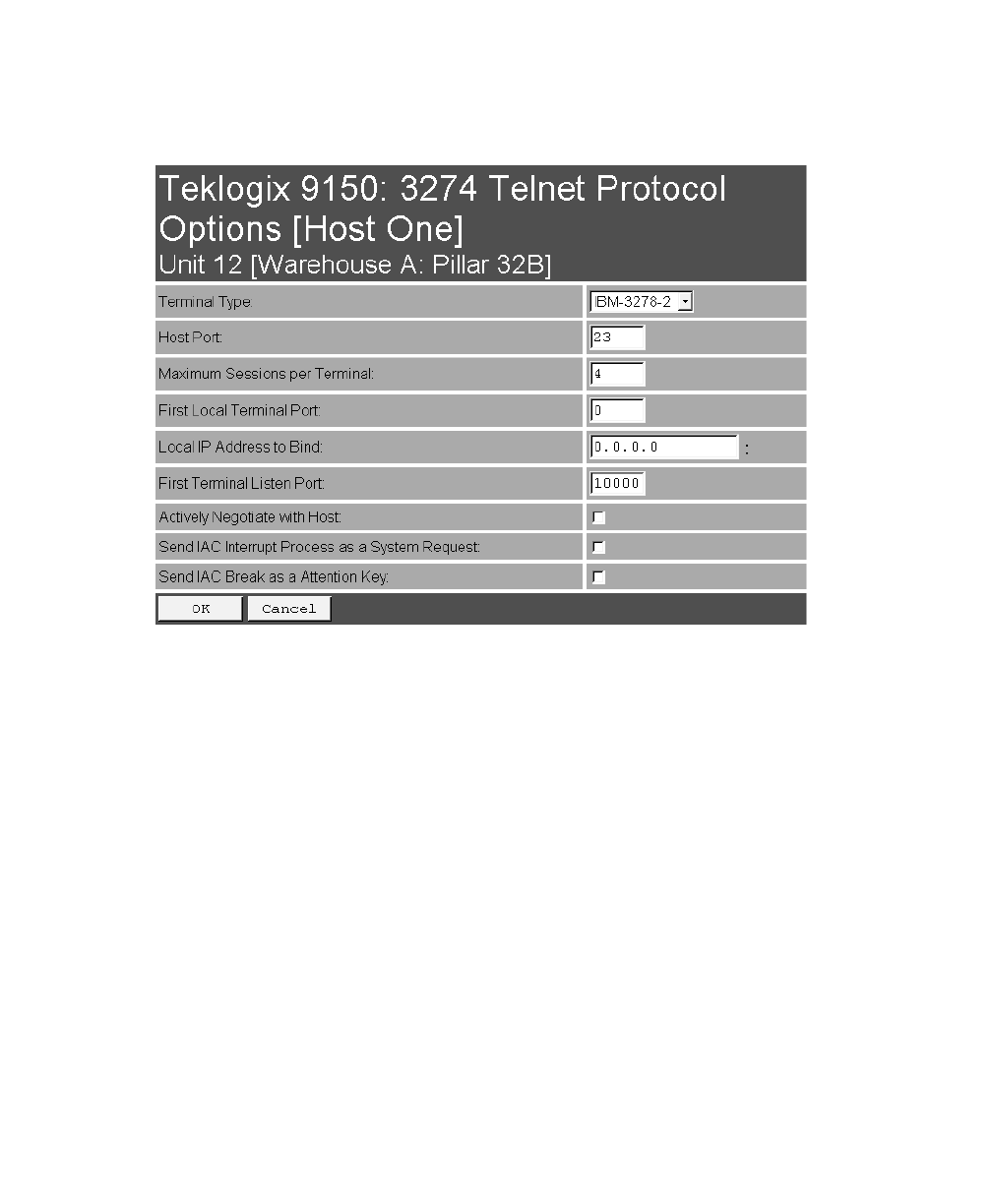
5.3.3.2 Protocol Options
This page differs depending on the type of emulation and protocol selected
in the General Host Options page. The 9150 displays this version of the Protocol
Options page when you select the emulation/protocol combination of 3274/Telnet
for this host.
Chapter 5: Mini-Controller Configuration
3274/Telnet
Protocol Options
96 Teklogix 9150 Wireless Gateway User Manual
Terminal Type
This parameter allows you to choose the type of terminal to be emulated by the 9150
for this host. At present there is only one choice of terminal for 3274/Telnet:
the IBM 3278-2.
Host Port
This parameter allows you to enter a host port value for the selected 3274/Telnet host
connection. The default value is 23.
Maximum Sessions per Terminal
This parameter contains the maximum number of telnet sessions which are allowed
to originate from each terminal. The range is 0 to 127, with a default value of 4.

Teklogix 9150 Wireless Gateway User Manual 97
Chapter 5: Mini-Controller Configuration
3274/Telnet
Protocol Options
First Local Terminal Port
This parameter contains the port number from which the first terminal will connect
on outbound telnet sessions. The default value is 0.
Local IP Address to Bind
This parameter contains the IP address of the network adaptor in the 9150 from
which the first terminal will connect on outbound telnet sessions.
First Terminal Listen Port
This parameter specifies the first port number at which the 9150 will listen for telnet
connection requests to the terminals. The default value is 10000.
Actively Negotiate with Host
If this parameter is enabled, the 9150 negotiates with the host during setup of the
telnet connection.
Send IAC Interrupt Process as a System Request
If this parameter is enabled, the 9150 sends the IAC Interrupt Process request to the
host as a 3274 System Request.
Send IAC Break as an Attention Key
If this parameter is enabled, the 9150 sends the IAC Break request to the host as a
3274 Attention key.
Chapter 5: Mini-Controller Configuration
3274/Telnet
Function Key Mappings
98 Teklogix 9150 Wireless Gateway User Manual
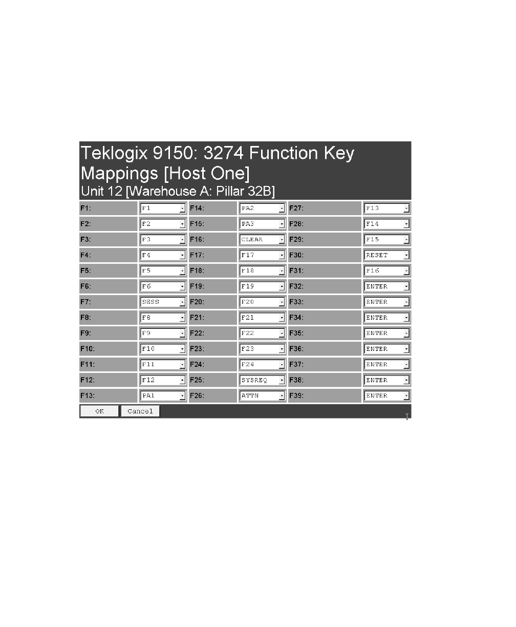
5.3.3.3 Function Key Mappings
This page differs depending on the type of emulation selected in the General Host
Options page. The 9150 displays this version of the Function Key Mapping page
when you select 3274 emulation for this host.
Function key n
The Function Key parameter allows you to select a code that will be sent to the host
when you press a function key on the terminal. Each function key may be chosen
from the same range of possible codes; however, each function key has a different
default code. The default values are shown on this page.
Teklogix 9150 Wireless Gateway User Manual 99
Chapter 5: Mini-Controller Configuration
5250/Telnet
Emulation Options
5.3.4 5250/Telnet
5.3.4.1 Emulation Options

Chapter 5: Mini-Controller Configuration
5250/Telnet
Emulation Options
100 Teklogix 9150 Wireless Gateway User Manual
The 9150 displays this version of the Emulation Options page after you have
selected the 5250/Telnet emulation/protocol combination for this host connection.
With IBM 5250, or IBM 3274 emulation, the 9150 mini-controller converts the
application data stream from the host to TESS (Teklogix Screen Subsystem)
commands. Some of the parameters in this page govern the conversion of the host
screens to TESS.
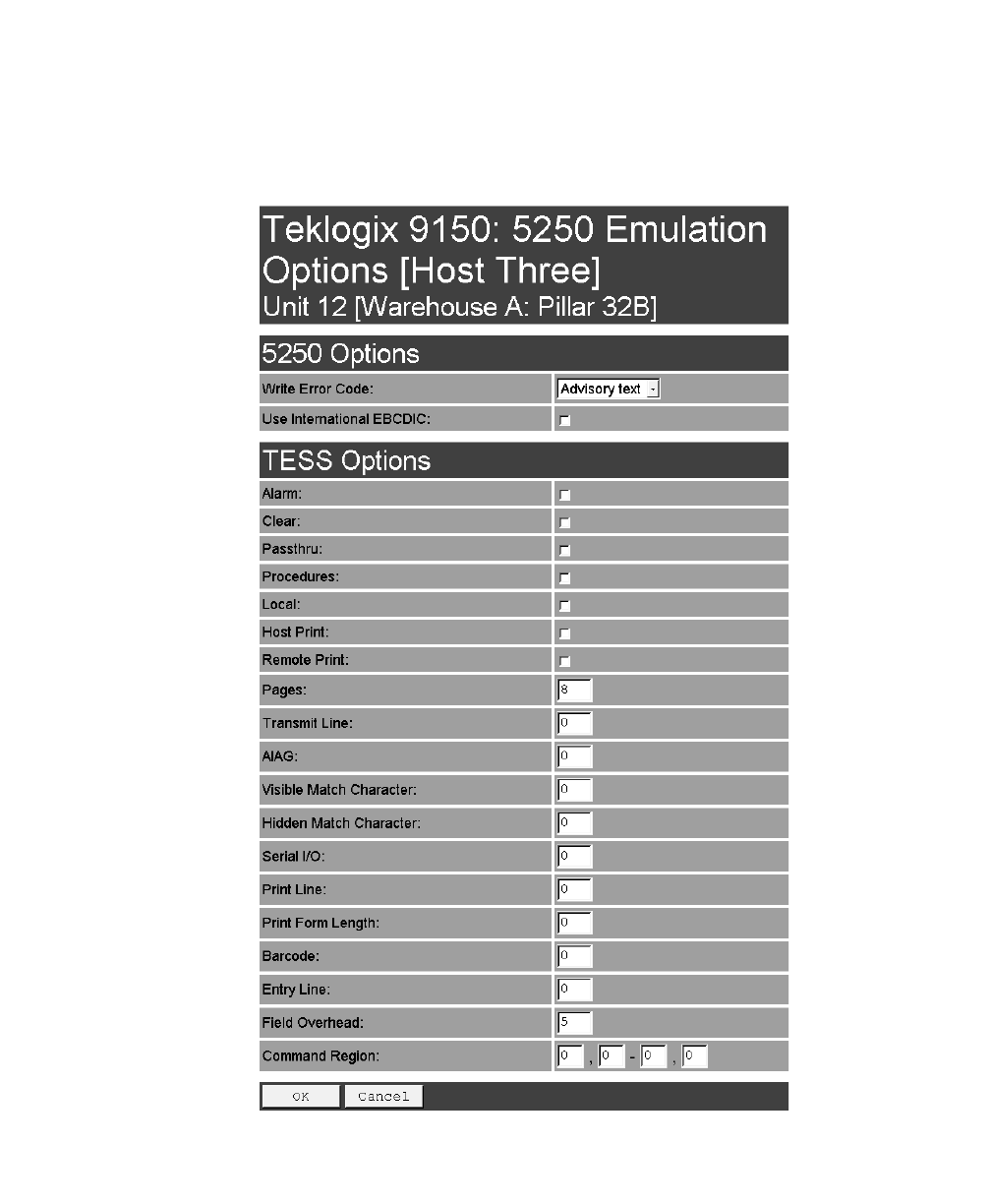
Write Error Code
If advisory text is selected here, the 9150 sends error codes to the terminal screen as
advisory text, which is written at the bottom of the screen. If screen text is chosen,
the 9150 sends the error codes as regular screen text.
Use International EBCDIC
If this parameter is enabled, the 9150 will swap the positions of the ! and ] charac-
ters in the EBCDIC character table.
Alarm
If this parameter is enabled, terminals will beep when the word “ALARM”
(in capital letters) appears on the application screen, in the location specified by the
Command Region parameter (see page 109). The word “ALARM” should be a
display-only field.
Note: The Command Region parameter must be enabled for this
parameter to work.
Clear
If this parameter is enabled, the 9150 mini-controller creates an empty entry field
for an entry field that is filled with spaces.
Some host applications rely on the video attributes of displayed characters to high-
light fields, particularly entry fields. For example, the application screen may define
all entry fields with reverse video and fill the field with spaces. This is effective on
terminals that support reverse video, but on terminals that do not, it can make the
field invisible since it is made up entirely of spaces.

Teklogix 9150 Wireless Gateway User Manual 101
Chapter 5: Mini-Controller Configuration
5250/Telnet
Emulation Options
By default, all empty entry fields displayed at the Teklogix terminal are highlighted
by the “entry character” chosen in the terminal’s configuration (not all Teklogix ter-
minals support video attributes). The Clear feature creates an empty entry field in
place of an entry field filled with spaces.
Note: This operation is only performed on screens received from the host. Data
sent to the host remains unaffected.
Passthru
If this parameter is enabled, the 9150 allows the host to send data directly to the RF
terminal’s serial port. This is most commonly used for printing.
Preparing Host Screens for Pass-Through
On the screen to be sent through the terminal serial port, the word “PASSTHRU”
(in capital letters) must appear on the first line, starting on the second column. The
actual data to be sent to the terminal may start anywhere below the first line.
With 5250 or 3274 emulations, attributes occupy a position in the screen buffer. An
attribute placed between column 2 and the end of the word “PASSTHRU” will push
all following characters one position to the right. Therefore, any required attributes
should occupy column 1 of the first line (just preceding the word “PASSTHRU”).
Example:
where @ is an attribute.
When the 9150 is finished sending the data to the terminal’s printer, it will send an
“ENTER” key to the host. The host must wait for the “ENTER” key before sending
any more screens (including other “PASSTHRU” screens) to this terminal.
Note: Refer to the 7030/8055/8060 Terminals User Manual for information
about setting parameters on the terminal for pass-through.
column: 1 2 3 4 5 6 7 8 9
line 1: @ P A S S T H R U @
line 2: @ P A R T : 1 2 3 4 5

Chapter 5: Mini-Controller Configuration
5250/Telnet
Emulation Options
102 Teklogix 9150 Wireless Gateway User Manual
Procedures
If this parameter is enabled, the host may send TESS procedures through the 9150
to the terminals. A TESS procedure is a group of TESS commands that can be exe-
cuted by the TESS execute procedure command.
Local
If this parameter is enabled, the 9150 allows the host to provide pages to be loaded
as local TESS procedures in the terminals.
The local procedures are selected from a menu at the terminal. The terminals can
perform these procedures when they are offline. Later when the terminals are online,
they send the results of these functions to the host.
Note: The Procedures parameter must also be enabled for Local to work.
Host Print
When this parameter is enabled, the host can send extra data to the terminal’s
screens, and instruct the terminal to print it. This is in contrast to the Local Print fea-
ture, where the terminal makes the initial print request.
The text that is passed to the printer is formatted into the 24 x 80 application screen.
If the host can initiate the print operation, the text is printed. The 9150 identifies the
additional text as a print page by the presence of the word “PRINT” (in capital let-
ters) beginning in the 2nd column of line 13 on the 24 x 80 screen. The word
“PRINT” should be defined as display-only text.
The print page is positioned below the terminal’s display page (see Figure 5.6 on
page 103). The size of the print page is always the same as the terminal’s display
page (assuming that in the terminal’s configuration, the page length is less than 12
lines).
When Host Print is enabled, the 9150 passes the print page to the terminal after
receiving the application screen from the host.
Teklogix 9150 Wireless Gateway User Manual 103
Chapter 5: Mini-Controller Configuration
5250/Telnet
Emulation Options
Figure 5.6 Application Screen With Print Page
Notes:
1. Unlike the Passthru option, when using Host Print no escape com-
mands can be sent to the printer.
2. Support for printing must be enabled at the terminal in its
Printer command under the TESS Features menu; refer to the
7030/8055/8060 Terminals User Manual for more information.
Remote Print
When this parameter is enabled, the 9150 sends the print page to a terminal when-
ever the terminal requests it (by sending the “F17” function key from the terminal,
or the “PRINT” key on older terminals). The 9150 sends the function response back
to the host.
This is in contrast to Host Print, where the host makes the initial print request.
Note: Support for printing must be enabled at the terminal level. Refer to the
7030/8055/8060 Terminals User Manual for more information.
1
2
3
4
5
6
7
8
9
10
11
12
13
14
15
16
17
18
19
20
21
22
23
24
Display Page (8 x 40)
Print Page (8 x 40)
PRINT

Chapter 5: Mini-Controller Configuration
5250/Telnet
Emulation Options
104 Teklogix 9150 Wireless Gateway User Manual
Pages
This parameter determines the number of host screens (or pages) stored at
the terminal, to a maximum of 16.
The 9150 reduces data transmitted to the terminals by using the terminal’s capability
to store a page of data for each screen it displays. The 9150 maintains an image of
each page stored at the terminal. After receiving an application screen, the 9150 tries
to match the screen with a stored page.
If a similar page is already in the terminal’s memory, the 9150 instructs the terminal
to re-display its copy of the page; only the necessary changes are sent from the con-
troller. If no match is found, the complete page is sent to the terminal over the
radio link.
Note: There is a corresponding parameter on the terminal itself, and the actual
number of saved pages will be the smaller of the two values.
Transmit Line
When this feature is enabled, all modified data at the terminal will be automatically
transmitted when the operator enters data into a transmit-upon-entry field.
The value in this textbox specifies the line on the screen which is designated the
transmit line. The last entry field above or on the transmit line on the screen will be
identified as the transmit-upon-entry field. If any entry fields exist on lines below
the transmit line, no entry field will be designated as the transmit-upon-entry field.
A value of 0 (zero) disables this feature. A value of 24 will cause the last entry field
on each application screen to be defined as transmit-upon-entry.
AIAG
This parameter provides auto-locate and fill for input coming from bar code readers.
When bar code data is entered at a terminal, the terminal searches for “AIAG” fields
on the current page that can accept the bar code data. The data preloaded into the
“AIAG” field by the application program determines whether or not the bar code
data is accepted.
At the 9150 mini-controller, a decimal value of an ASCII character from 0 to 127
is set to match the “AIAG Field Identifier” set at the host. A value of 0 disables
this feature.

Teklogix 9150 Wireless Gateway User Manual 105
Chapter 5: Mini-Controller Configuration
5250/Telnet
Emulation Options
The format of the preloaded data is as follows:
<mode> <AIAG prefix(data)>
The mode character used with the command allows for different operating modes to
suit various application operations. The automatic locate and fill operation applies
only to data received from a bar code reader. Descriptions of the modes and AIAG
prefix are listed in the table below. These modes are set at the host.
Table 5.3 Mode Functions And AIAG Prefix Description
Mode Function
0Display prefix, send prefix to host.
1Do not display prefix, send prefix to host.
2Display prefix, do not send prefix to host.
3Do not display prefix, do not send prefix to host.
+4
Add 4 to above values to cause transmit to host when all AIAG fields with 4
set are filled. Function 0 is “pressed” if there are any fields
with this bit set, and all fields with this bit set have been filled by
operator input.
+8 Add 8 to above values to allow overwrite of previously entered data.
+16 Add 16 to above values to indicate cursor position priority for search and fill.
AIAG Prefix
(data) The text to be matched in the AIAG field.
Chapter 5: Mini-Controller Configuration
5250/Telnet
Emulation Options
106 Teklogix 9150 Wireless Gateway User Manual
Example:
The information in the sample screen below is defined at and sent from the host. It
includes the “AIAG Identifier” – the tag identifying this as an AIAG field – followed
by the mode, in this case Mode 0, and finally, the “AIAG Prefix” – I.
Figure 5.7 AIAG Field Sent From The Host
When the information arrives at the terminal screen, the appropriate AIAG field for
the scanned information is located using the “AIAG Identifier”. Because Mode 0
was set at the host, the “AIAG Prefix” – I – is displayed on the terminal screen, and
when this screen is completed, the prefix will be sent back to the host.
Figure 5.8 AIAG Field Sent To The Terminal
Visible Match Character
By inserting a special ASCII character directly before an entry field, the application
program distinguishes a “match field” from an entry field. For example, suppose an
angle bracket “>” is defined for visible match fields. Inserting “>” immediately
preceding the entry field identifies it as a match field, as illustrated below.
Part #> ___________
Item No. @0
AIAG Information From Host
AIAG Prefix (data)
Mode
AIAG Field Identifier
I
Item No. I
AIAG Information From Host To Terminal Screen
@
AIAG Prefix (data)
AIAG Field Identifier

Teklogix 9150 Wireless Gateway User Manual 107
Chapter 5: Mini-Controller Configuration
5250/Telnet
Emulation Options
The range for this parameter – 0 to 127 – represents the decimal values of
ASCII characters. A value of 0 disables this feature. The ASCII decimal value
entered at the 9150 must coincide with the value set by the application program.
To use the Visible Match feature, the host computer preloads data into a match
entry field; the data is visible on the terminal screen. The preloaded data sent to a
terminal can consist of exact characters, special match characters or a combination
of the two. Refer to the table below for match characters recognized by
Teklogix terminals.
If an entry does not match the preloaded data, the entry is displayed, the terminal
beeps, and the cursor moves to the first position in the match field. The operator can
either make another entry in the match field, or move the cursor to a new field.
When an entry (even one that doesn’t match the preloaded data) is made in a match
field, the entry is sent to the host as part of the terminal’s modified data during the
next transmission.
Table 5.4 Match Characters
Character Description
#Match a number.
&Match a letter (either case).
^Match an uppercase letter.
_Match a lowercase letter.
|Match an alphanumeric character.
"Match a letter, number or space.
?Match a punctuation character.
'Match any character.
:Match all character positions in the field with the preceding character.
;Match any remaining characters, but not necessarily the remainder of the field,
with the preceding character.

Chapter 5: Mini-Controller Configuration
5250/Telnet
Emulation Options
108 Teklogix 9150 Wireless Gateway User Manual
Example:
Suppose you want to preload an entry field with a part number. If the part number is
known, you can preload the field with that part number. If more flexibility is needed,
and the part number always begins with two alphabetic characters followed by a
hyphen and four digits, the match string for the field would be: &&–#### .
Hidden Match Character
Unlike data in a “visible match” field, the preloaded data in a “hidden match” field
is not displayed at the terminal.
Note: Refer to “Visible Match Character” on page 106 for detailed information
about field matching.
The range for this parameter – 0 to 127 – represents the decimal values of ASCII
characters. A value of 0 disables this feature. The ASCII decimal value entered at
the 9150 must coincide with the value set by the application program.
Serial I/O
Serial I/O fields are special entry and fixed fields that accept input from and output
to a serial port. The application program distinguishes this field as Serial I/O by pre-
ceding the field with a special character.
If this character precedes a fixed field, the data will be sent to the terminal’s serial
port. If it precedes an entry field, the field accepts data from the terminal’s
serial port.
The range for this parameter – 0 to 127 – represents the decimal values of ASCII
characters. A value of 0 (zero) disables this feature.
Print Line
This parameter allows you to enter the starting line number of the print page in the
application screen. A value of 1 causes the display page to be printed; a value of 0
(zero) disables this feature.
Print Form Length
This parameter sets the printer’s form length in lines. The range is 0 to 24.

Teklogix 9150 Wireless Gateway User Manual 109
Chapter 5: Mini-Controller Configuration
5250/Telnet
Emulation Options
Barcode
Barcode-input-only fields are special entry fields that only accept input from a bar
code reader. The application program distinguishes an entry field as barcode-input-
only by preceding the field with a special character.
The range for this parameter – 0 to 127 – represents the decimal values of ASCII
characters. A value of 0 (zero) disables this feature.
Entry Line
This parameter contains the number of the first line displayed if there is no entry
field in the upper-left portion of the screen, and if an entry field is at or below
this line.
The Entry Line parameter allows an automatic offset within the host screen, so that
the area displayed by the terminal includes an entry field that would normally be out
of bounds. Normally, Teklogix terminals only display the upper-left corner of the
application screen because of their smaller display size.
Field Overhead
This parameter contains the maximum number of characters allowed between two
fixed fields which still allows the 9150 to join them into one field.
Sometimes the 9150 will join two adjacent fixed fields and then send them as one
field. This reduces the overhead on the radio link.
For example, if two fields were 4 characters apart and this parameter was ‘5’, then
these fields would be joined into one.
Command Region
This parameter defines a region of the host screen which the 9150 will examine for
the presence of reserved commands.
The four numbers in the Command Region textboxes represent the row and column
addresses of the upper left corner and the lower right corner of the command region.
The first textbox of each pair contains the row number; the second contains the
column number. The range of row values is 0 to 24; column values are 0 to 80.
To define the last two lines of the host screen as the command region, for example,
enter the values 23, 1 and 24, 80.
Chapter 5: Mini-Controller Configuration
5250/Telnet
Protocol Options
110 Teklogix 9150 Wireless Gateway User Manual
Currently, the only command supported is ALARM (refer to page 100 for details on
this command). When the word “ALARM” is placed anywhere within the command
region, the 9150 will send a TESS beep command to the terminal.
5.3.4.2 Protocol Options
This page differs depending on the type of emulation and protocol selected in the
General Host Options page. The 9150 displays this version of the Protocol Options
page when you select the emulation/protocol combination of 5250/Telnet for
this host.
Terminal Type
This parameter allows you to choose the type of terminal to be emulated by the 9150
for this host. At present there are two choices of terminal for 5250/Telnet:
the IBM 5251-11 and IBM 5555-B01.
Host Port
This parameter allows you to enter a host port value for the selected 5250/Telnet host
connection. The default value is 23.

Teklogix 9150 Wireless Gateway User Manual 111
Chapter 5: Mini-Controller Configuration
5250/Telnet
Protocol Options
Maximum Sessions per Terminal
This parameter contains the maximum number of telnet sessions which are allowed
to originate from each terminal. The range is 0 to 127, with a default value of 4.
First Local Terminal Port
This parameter contains the port number from which the first terminal will connect
on outbound telnet sessions. The default value is 0.
Local IP Address to Bind
This parameter contains the IP address of the network adaptor from which the first
terminal will connect on outbound telnet sessions.
First Terminal Listen Port
This parameter specifies the first port number at which the 9150 will listen for telnet
connection requests to the terminals. The default value is 0.
Actively Negotiate with Host
If this parameter is enabled, the 9150 negotiates with the host during setup of the
telnet connection.
Chapter 5: Mini-Controller Configuration
5250/Telnet
Function Key Mappings
112 Teklogix 9150 Wireless Gateway User Manual
5.3.4.3 Function Key Mappings
This page differs depending on the type of emulation selected in the General Host
Options page. The 9150 displays this version of the Function Key Mapping page
when you select 5250 emulation for this host.
Function key n
The Function Key parameter allows you to select a code that will be sent to the host
when you press a function key on the terminal. Each function key may be chosen
from the same range of possible codes; however, each function key has a different
default code. The default values are shown on this page.
Teklogix 9150 Wireless Gateway User Manual 113
Chapter 5: Mini-Controller Configuration
ANSI/Telnet
Emulation Options
5.3.5 ANSI/Telnet
5.3.5.1 Emulation Options
The 9150 displays this version of the Emulation Options page after you have
selected the ANSI/Telnet emulation/protocol combination for this host connection.
Host Timeout
The Host Timeout is the interval (in ticks, or 60ths of a second) between bursts of
data received from the host. The range is 0 to 255, with a default value of 15.
If the 9150 does not receive any characters from the host after this timeout has
elapsed, it assumes that the host has finished sending data and is waiting for user
input (in other words, it assumes that a screen of data has been completed).
Important: The Page parameter (page 115) must be enabled in order to change
the value in the Host Timeout parameter.
Chapter 5: Mini-Controller Configuration
ANSI/Telnet
Emulation Options
114 Teklogix 9150 Wireless Gateway User Manual
Escape Timeout
The Escape Timeout is the length of time (in ticks, or 60ths of a second) that the
9150 will hold an “ESC” received from the host, and consider the next received byte
to be part of an escape sequence. The range is 0 to 255, with a default value of 12.
When this timeout has elapsed, the host will have to send another “ESC” character
to start an escape sequence.
Note: This is especially important when an ESC is at the end of a data packet.
Threshold
The Threshold is the minimum number of bytes of update data for the terminal
screen which must be received from the host before the 9150 will store the screen as
a new “saved page”. The range is 0 to 999, with a default value of 200.
Important: The Page parameter (page 115) must be enabled in order to change
the value in the Threshold parameter.
Echo
If this parameter is enabled, the 9150 uses “Smart” Echo. This mode reduces the
amount of data sent to the terminal by decreasing the number of radio transmissions.
Ordinarily, when a character mode application is being used, each keystroke is sent
to the host in one transmission, and the character is echoed by the host in another
transmission. When “Smart” Echo is enabled, the 9150 will not send the host echo
to the terminals if it matches the data sent from the terminal. Thus, the number of
radio transmissions is reduced.
This mode also reduces or eliminates the delay between typing a character on the
keyboard and displaying the character echoed by the host. The maximum number of
characters waiting for echo is 25. Any additional characters will be sent to the host
but not displayed.
Notes:
1. This parameter also determines whether an ANSI parameter query is
sent to the terminal.
2. “Smart” Echo also needs to be enabled at the terminal (refer to the
7030/8055/8060 Terminals User Manual).

Teklogix 9150 Wireless Gateway User Manual 115
Chapter 5: Mini-Controller Configuration
ANSI/Telnet
Emulation Options
ANSI
If this parameter is enabled, the 9150 uses ANSI escape code filtering. When
escape-code filtering is enabled, ANSI escape codes not supported by the
terminals will be filtered out of the data stream to reduce radio traffic. The terminals
currently support most, if not all, standard ANSI escape sequences, so this parame-
ter should be disabled in most cases.
Function Key Remapping
If this parameter is enabled, the 9150 remaps the function keys for this host
connection as defined in the Function Key Remapping page (page 121).
Page
If this parameter is enabled, the 9150 uses page saving, reducing data
transmitted to the terminals.
The 9150 maintains an image of each page stored at the terminal. After receiving an
application screen, the 9150 tries to match the screen with a stored page. If the page
is already in the terminal, the 9150 instructs the terminal to redisplay its stored copy
of the page; no data need be sent across the radio link for that page. If the 9150 finds
no match for the page, the complete page is sent to the terminal.
Note: When page saving is enabled, the number of saved pages is that which is
set on the terminal. Refer to the 7030/8055/8060 Terminals User Manual
for details.
RLE
If this parameter is enabled, the 9150 uses run-length encoding (RLE) on the data it
sends across the radio link. RLE compresses repeated characters going from the host
to the terminal. If repeated characters are found in the data stream, the first one is
sent, followed by a short escape sequence (3 or 4 characters) which tells the terminal
how many times to repeat this character. In this way RLE compresses the data and
decreases the total amount of radio-link traffic.
Convert 7 to 8 Bits
If this parameter is enabled, the 9150 converts 7-bit control sequences to their 8-bit
equivalents in ANSI data streams going to the terminals. This replaces two-charac-
ter escape sequences with a single equivalent character, compressing the data.
Chapter 5: Mini-Controller Configuration
ANSI/Telnet
Protocol Options
116 Teklogix 9150 Wireless Gateway User Manual
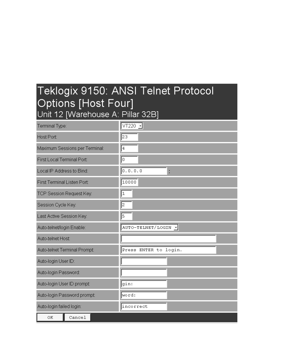
5.3.5.2 Protocol Options
This page differs depending on the type of emulation and protocol selected in the
General Host Options page. The 9150 displays this version of the Protocol Options
page when you select the emulation/protocol combination of ANSI/Telnet for
this host.

Teklogix 9150 Wireless Gateway User Manual 117
Chapter 5: Mini-Controller Configuration
ANSI/Telnet
Protocol Options
Terminal Type
This parameter specifies the type of terminal to be emulated by the 9150, either a
VT100 or VT200.
Host Port
This parameter specifies the value for the host port for the selected ANSI host con-
nection. The default value is 23.
Maximum Sessions per Terminal
This parameter contains the maximum number of telnet sessions which are allowed
to originate from each terminal. The range is 0 to 127, with a default value of 4.
First Local Terminal Port
This parameter specifies the port number from which the 9150 attempts a telnet con-
nection for the first terminal. The default value is 0.
Additional telnet sessions are assigned higher port numbers.
Local IP Address to Bind
This parameter specifies the IP address of the 9150 interface that connects to this
host. It is used along with the local port numbers to create a unique socket for each
terminal session.
First Terminal Listen Port
This parameter specifies the lowest port number at which the 9150 listens for telnet
connections initiated by the host. The default value is 10000.
TCP Session Request Key
This parameter contains the decimal ASCII character code of the character which
will prompt the terminal to request a new ANSI terminal session. The range is 0 to
255, with a default value of 1.

Chapter 5: Mini-Controller Configuration
ANSI/Telnet
Protocol Options
118 Teklogix 9150 Wireless Gateway User Manual
Session Cycle Key
This parameter contains the decimal ASCII character code of the character which
will prompt the terminal to display the next ANSI terminal session. The range is 0 to
255, with a default value of 2.
Last Active Session Key
This parameter contains the decimal ASCII character code of the character which
will prompt the terminal to display the last ANSI terminal session. The range is 0 to
255, with a default value of 5.
Auto-telnet/login Enable
This parameter enables you to disable or enable automatic connection of telnet ses-
sions from terminals to this host. The choices provided are: Disable; Enable Auto-
telnet; Enable Auto-telnet/login. The default value is Disable.
When Auto-telnet is disabled, telnet sessions from the terminals to the host must be
initiated manually from the terminals.
When Auto-telnet is enabled, the 9150 initiates one telnet session from each termi-
nal whose terminal number is mapped to this host. Additional telnet sessions may be
initiated from each terminal to the host, but they must be initiated manually.
Note: Auto-telnet sessions are only initiated for terminals which are “online”
(turned on and operating properly on the Teklogix RF network).
When Auto-telnet and Auto-login are enabled, the 9150 initiates one telnet session
from each terminal whose terminal number is mapped to this host. It then logs each
session in to the host using the User ID and Password provided in this page.
Note: The User ID and Password is identical for all Auto-telnet sessions
automatically logged in to this host.

Teklogix 9150 Wireless Gateway User Manual 119
Chapter 5: Mini-Controller Configuration
ANSI/Telnet
Protocol Options
Auto-telnet Host
This parameter contains the host name or IP address for the host to which the 9150
connects Auto-telnet sessions.
Note: A host name placed in this textbox must be “resolvable” by the 9150:
the 9150 must be able to obtain an IP address for it. For example, the host
name may correspond to an entry in the 9150’s host table, or the 9150
may be able to query a domain-name server.
Any host name which can be used at the terminal’s TCP> prompt may be
used here.
Auto-telnet Terminal Prompt
This parameter contains the text presented to the user to request a login. The charac-
ters can be any ASCII string, with a maximum of 32 characters. The default is no
text, just press <ENTER> to login.
Auto-login User ID
This parameter contains the user ID presented by the 9150 to the host for the
Auto-login sessions. The characters can be any ASCII string acceptable to the host,
with a maximum of 15 characters.
Auto-login Password
This parameter contains the password presented by the 9150 to the host for the
Auto-login sessions. The characters can be any ASCII string acceptable to the host,
with a maximum of 15 characters.
Auto-login User ID prompt
The 9150 compares the text in this textbox to the text presented to it by the host.
When they match, the 9150 assumes that the host has just sent its request for a user
name, and it sends the user ID specified in the Auto-Login User ID parameter to the
host. The characters can be any ASCII string, with a maximum of 15 characters.
The default text is gin: .
Note: The match string should be as short as possible, yet long enough to
uniquely identify the user-ID prompt. Do not include multi-part words
separated by space characters, since some hosts send out characters
other than space characters to present a space on the screen.

Chapter 5: Mini-Controller Configuration
ANSI/Telnet
Protocol Options
120 Teklogix 9150 Wireless Gateway User Manual
Auto-login Password prompt
The 9150 compares the text in this textbox to the text presented to it by the host.
When they match, the 9150 assumes that the host has just sent its request for a pass-
word, and it sends the password specified in the Auto-Login Password parameter to
the host. The characters can be any ASCII string, with a maximum of 15 characters.
The default text is word: .
Note: The match string should be as short as possible, yet long enough to
uniquely identify the password prompt. Do not include multi-part words
separated by space characters, since some hosts send out characters
other than space characters to present a space on the screen.
Auto-login failed login
The 9150 compares the text in this textbox to the text presented to it by the host.
When they match, the 9150 assumes that the host has just sent a string informing the
terminal of a failed login attempt. The 9150 then presents the Auto-telnet Terminal
Prompt on the terminal’s screen to request the user to login manually. The characters
can be any ASCII string, with a maximum of 15 characters. The default text
is incorrect .
Note: The match string should be as short as possible, yet long enough to
uniquely identify the failed-login prompt. Do not include multi-part words
separated by space characters, since some hosts send out characters
other than space characters to present a space on the screen.

Teklogix 9150 Wireless Gateway User Manual 121
Chapter 5: Mini-Controller Configuration
ANSI/Telnet
Function Key Mappings
5.3.5.3 Function Key Mappings
This page differs depending on the type of emulation selected in the General Host
Options page. The 9150 displays this version of the Function Key Mapping page
after you have selected the ANSI/Telnet emulation/protocol combination for this
host connection.

Chapter 5: Mini-Controller Configuration
ANSI/Telnet
Function Key Mappings
122 Teklogix 9150 Wireless Gateway User Manual
Function key n
The Function Key parameter allows you to select a code that will be sent to the host
when you press a function key on the terminal. Each function key may be chosen
from the same range of possible codes; however, each function key has a different
default code. The default values are shown on the screen on page 121.