Contents
- 1. TRX7431 User Manual
- 2. Teklogix 9150 Wireless Gateway User Manual
- 3. Teklogix 9150 Wireless Gateway User Manual Declaration of Conformity
- 4. Teklogix 9150 Wireless Gateway User Manual Cautions to Users
- 5. Teklogix 9150 Wireless Gateway User Manual Teklogix Offices
- 6. Teklogix 9150 Wireless Gateway User Manual Table of Contents
- 7. Teklogix 9150 Wireless Gateway User Manual Chapter 1 Introduction
- 8. Teklogix 9150 Wireless Gateway User Manual Chapter 2 Installation Requirements
- 9. Teklogix 9150 Wireless Gateway User Manual Chapter 3 9150 Main Configuration
- 10. Teklogix 9150 Wireless Gateway User Manual Chapter 4 Base Station Configuration
- 11. Teklogix 9150 Wireless Gateway User Manual Chapter 5 Mini Controller Configurati
- 12. Teklogix 9150 Wireless Gateway User Manual Chapter 6 Access Point Configuration
- 13. Teklogix 9150 Wireless Gateway User Manual Chapter 7 Specifications
- 14. Teklogix 9150 Wireless Gateway User Manual Appendix A
- 15. Teklogix 9150 Wireless Gateway User Manual Appendix B
- 16. Teklogix 9150 Wireless Gateway User Manual Index
- 17. Teklogix 9150 Wireless Gateway User Manual Appendix A
- 18. 7035 8255 8260 User Manual
- 19. 9150 User Manual
- 20. response to FCC correspondence 15472
Teklogix 9150 Wireless Gateway User Manual Chapter 3 9150 Main Configuration

Teklogix 9150 Wireless Gateway User Manual 23
9150 MAIN CONFIGURATION 3
3.1 Configuration Main Menu....................25
3.2 Configuring The IP Address...................25
3.3 Accessing The Menus ......................27
3.4 General Configuration Options.................29
3.4.1 Interfaces.......................30
3.4.1.1 Onboard Ethernet . . . . . . . . . . . . . . . 30
3.4.1.2 Slot n: Token-Ring. . . . . . . . . . . . . . . 32
3.4.1.3 Slot n: PC Card Radio . . . . . . . . . . . . . 34
3.4.2 Users.........................34
3.4.3 SNMP........................35
3.4.3.1 System Parameters. . . . . . . . . . . . . . . 36
3.4.3.2 SNMP Communities..............36
3.4.3.3 Trap Receivers.................36
3.4.4 TCP/IP Parameters..................36
3.4.4.1 Host Table...................37
3.4.4.2 Bootp .....................38
3.4.4.3 DNS......................39
3.4.5 Serial Ports Parameters................40
3.4.5.1 Console Port . . . . . . . . . . . . . . . . . . 40
3.4.5.2 Serial Port...................40
3.5 Access Point/Base Station Configurations. ...........41
3.6 Miscellaneous Commands . . ..................42
3.6.1 System Info .....................42
3.6.2 Reboot Unit . . . . . . . . . . . . . . . . . . . . . 43


Teklogix 9150 Wireless Gateway User Manual 25
Chapter 3: 9150 Main Configuration
Configuration Main Menu
3.1 Configuration Main Menu
The 9150 Flash memory can be reconfigured remotely via the network using a
standard HTML Web Browser such as Netscape Navigator (version 4.05 or later) or
MS Internet Explorer (version 4.0 or later). The 9150 Configuration program allows
various configuration parameter settings to be changed, added or deleted.
Important: The 9150 must be warm rebooted after parameter changes are made ,
including configuring the IP address (see below), in order for the
changes to take effect. For details, see “Reboot Unit” on page 43.
3.2 Configuring The IP Address
Before the configuration menus can be accessed using your Web Browser, the 9150
must be assigned an IP address using a PC console connection. Virtually any PC
can be connected to the console port of the 9150, provided that the PC has a
terminal communication program such as the Windows “HyperTerminal” utility or
“Procomm Plus” for Windows. These programs emulate an ANSI terminal such as
VT220 or higher. Cable no. 19387 should be used to connect the PC to the 9150.
Make sure the communications settings on your PC are set to 8 bits, 1 stop, no
parity, and that the baud rate of the serial port matches that of the 9150 console port
(19,200 baud).
After the PC is attached and turned on, press the <RETURN> key several times until
the “>” prompt appears. The commands used to configure IP addresses are
described here.
If your system uses a bootp server to assign IP addresses, make sure that “bootp” is
enabled. Once enabled, and the 9150 is rebooted, you will be able to access the
9150 configuration menus through the Web Browser, using the IP address identified
in the server's bootp table. If you do not use a bootp server, make sure that “bootp”
is disabled and continue with the configuration commands to manually assign an
IP address.
Important: When your configuration is completed, the changes should be
saved to flash by entering the following command (commands are
case-sensitive):
>cfg commitCache

Chapter 3: 9150 Main Configuration
Configuring The IP Address
26 Teklogix 9150 Wireless Gateway User Manual
To display the bootp setting:
>cfg get system.dobootp
To enable bootp:
>cfg put system.dobootp 1
To disable bootp:
>cfg put system.dobootp 0
To display the default IP address (xxx.xxx.xxx.xxx represents the IP address):
>cfg get interface.1.defaultipaddress
To configure the default IP address
>cfg put interface.1.defaultipaddress xxx.xxx.xxx.xxx
To display the default gateway:
>cfg get system.defaultgateway
To configure the default gateway:
>cfg put system.defaultgateway xxx.xxx.xxx.xxx
To display the default subnetmask:
>cfg get interface.1.defaultsubnetmask
To configure the default subnetmask:
>cfg put interface.1.defaultsubnetmask xxx.xxx.xxx.xxx

Teklogix 9150 Wireless Gateway User Manual 27
Chapter 3: 9150 Main Configuration
Accessing The Menus
3.3 Accessing The Menus
When the Web Browser is pointed to the 9150’s IP address, a name and password
dialog box appears. The password is comprised of alphanumeric characters and is
case-sensitive. If you change the password (see “Users” on page 34), set all 9150s to
the same password, and write it down in a secure place.
A default user name “user” and the password “123456” are created on 9150 system
startup if no users are already configured. You can use the default to enter the
Configuration Main Menu for the first time. For security, change this default name
and password immediately after entering the configuration menus. Should you acci-
dentally delete your user names, re-booting the 9150 will re-create the default name
and password so that you can get back in to the unit.
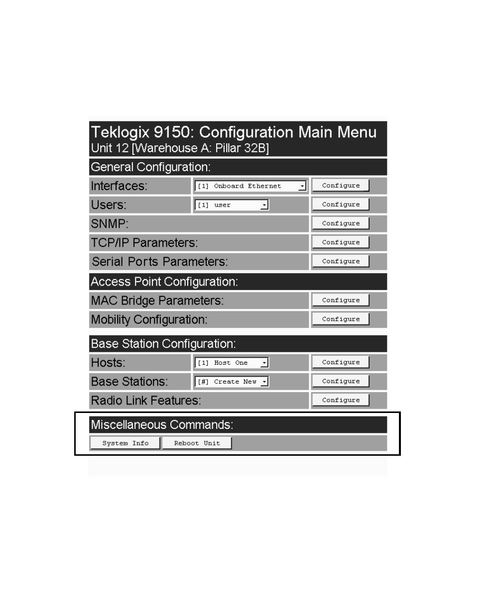
After the password is accepted, the Configuration Main Menu appears. The 9150
software automatically detects the system information of the unit, and most of the
parameters have already been properly configured for each site.
Warning: Parameters should not be altered without a clear understanding of
how they operate. Parameters that are incorrectly set can increase
response time or cause communication difficulties.
•To highlight and move through the different options, use the <TAB> key
or mouse pointer.
•To view and select the items in the listboxes, either press the <UP> or
<DOWN> arrow keys or click on the arrow at the side of the menu and
highlight the item.
•To enter the related configuration sub-menu dialog box, highlight
“Configure” and either press <ENTER> or click on the “Configure” button.
•Where string entry parameters are given in the menus, changes are keyed in.
Numerical parameters can be entered as hexadecimal values. Precede hexa-
decimal values with “0x”.
•To leave a menu page, select either the <OK> or <Cancel> button at
the bottom of the page. Selecting <OK> will save your changes and
exit the page, while selecting <Cancel> will exit the page without saving
the changes.
Important: Do not use the Web Browser’s <Back> button to leave a page.
Chapter 3: 9150 Main Configuration
Accessing The Menus
28 Teklogix 9150 Wireless Gateway User Manual
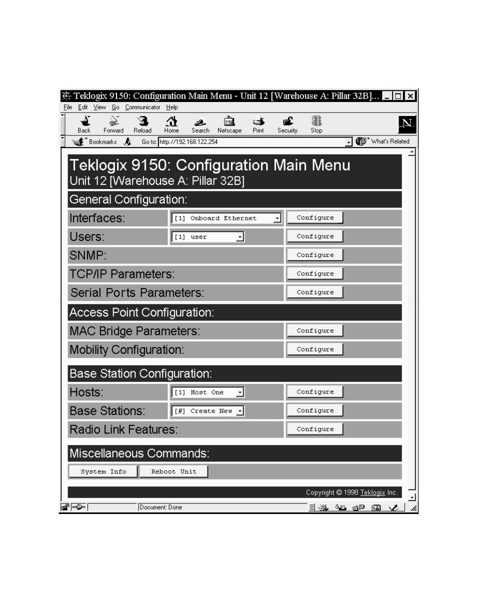
Figure 3.1 9150 Configuration Main Menu: View From Browser
Teklogix 9150 Wireless Gateway User Manual 29
Chapter 3: 9150 Main Configuration
General Configuration Options
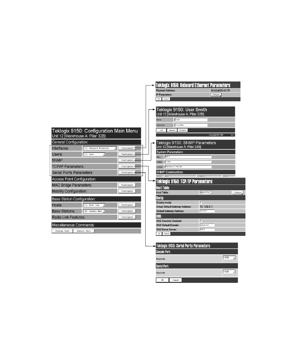
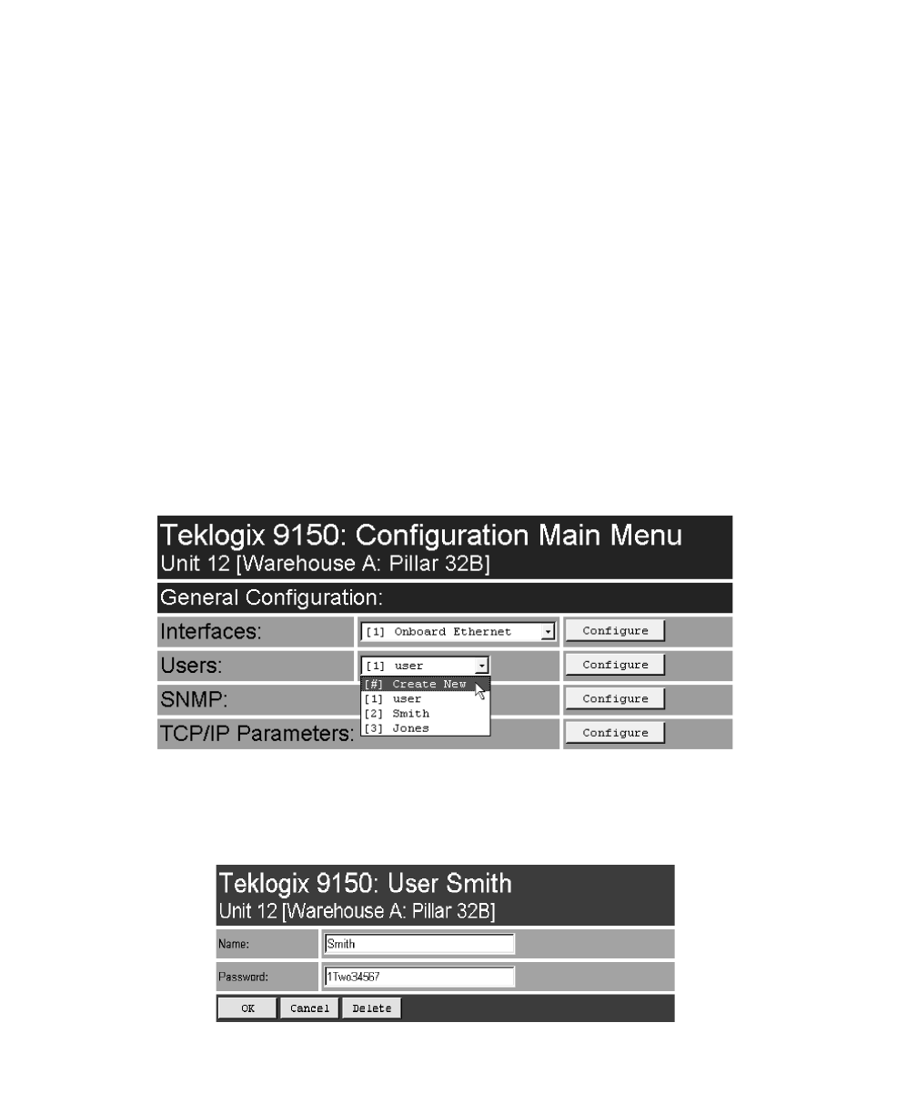
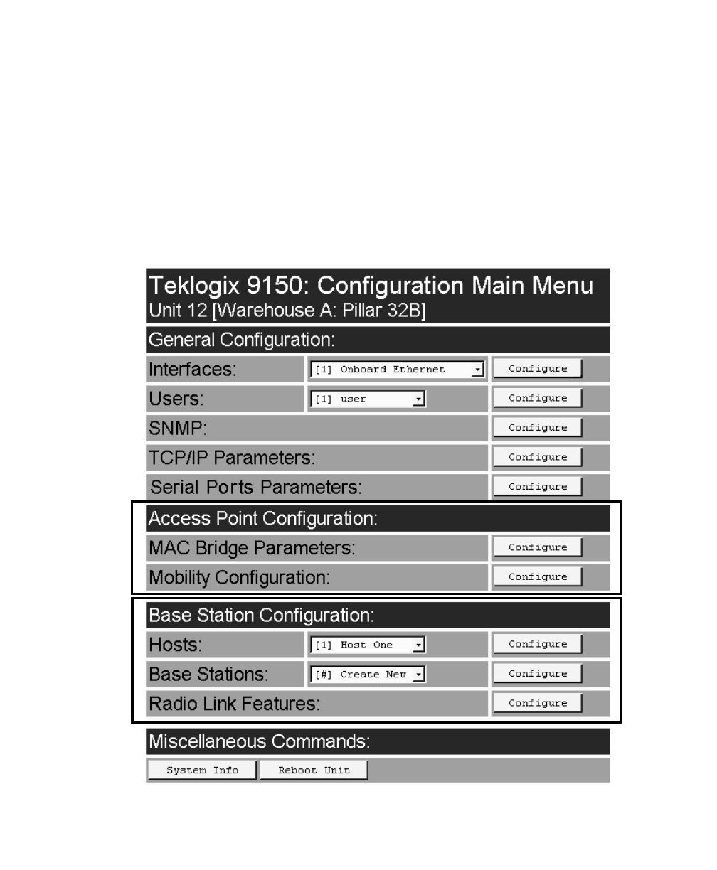
3.4 General Configuration Options
The General Configuration menu on the Configuration Main Menu page presents
five options of sub-menus: Interfaces , Users, SNMP, TCP/IP Parameters, and
Serial Ports Parameters.
Figure 3.2 Overview Of General Configuration Menus
Chapter 3: 9150 Main Configuration
Interfaces
30 Teklogix 9150 Wireless Gateway User Manual
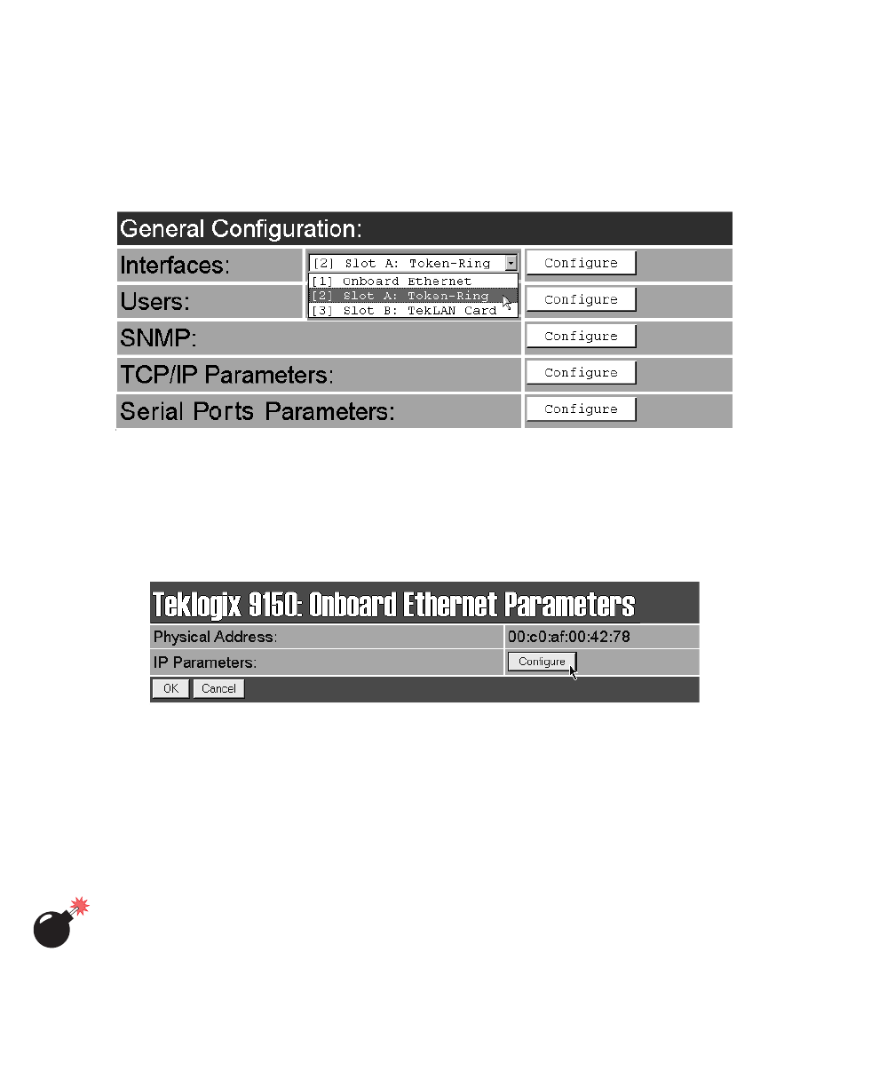
3.4.1 Interfaces
The pull-down menu shown for the Interfaces option indicates which interfaces have
been detected in use by the 9150.
3.4.1.1 Onboard Ethernet
For the selection Onboard Ethernet, entering the “Configure” dialog box will open
the parameters page for the Ethernet connection, which shows the 9150’s physical
(hardware) address and IP address parameters.
Physical Address
A unique Physical Address is assigned by Teklogix personnel for each 9150. The
values entered for this parameter are presented in hexadecimal in descending order
beginning with the MSB (Most Significant Byte), the highest value, and ending with
the LSB (Least Significant Byte), the lowest value. The allowable value for each
field ranges from 00 to FF.
Warning: It is not advisable to modify the Physical Address. However, if these
values are changed, the Network Administrator must assign a
unique address to each Ethernet station on the network, including
all 9150s.
Teklogix 9150 Wireless Gateway User Manual 31
Chapter 3: 9150 Main Configuration
Interfaces
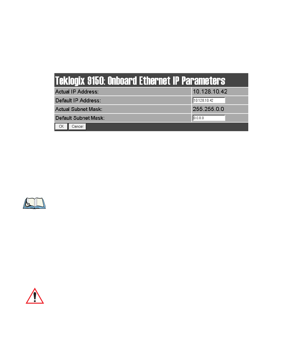
IP Parameters
Each 9150 that is connected to a local network has a unique IP address designated
for it. The IP Parameters used to assign the IP address are accessed by entering the
“Configure” dialog box.
Actual IP Address
The Actual IP Address is the IP address currently set on the 9150.
Default IP Address
This parameter allows you to change the value of the IP address. The IP
address must be a unique value on the network, including any Token Ring
IP addresses being used, so that each 9150 in your system can be identified.
The acceptable value ranges from 0.0.0.0 to 239.255.255.255.
Note: The value 255.255.255.255 is reserved for the broadcast address.
Actual Subnet Mask
The Actual Subnet Mask is the subnet mask currently set on the 9150.
Default Subnet Mask
This parameter allows you to change the value of the subnet mask. The 9150 uses
the Default Subnet Mask, its own IP address, and the destination IP address to deter-
mine if a packet should be sent on the local network or to a remote segment. If the
destination is found on the local network, the packet is sent directly to its destina-
tion. If the destination resides on a remote network, the packet is routed to the gate-
way. Enter your subnet mask in “xxx.xxx.xxx.xxx” notation.
Important: The maximum packet size supported is 1500 bytes. This parameter
is not set at the 9150, but should be set at the host.
Chapter 3: 9150 Main Configuration
Interfaces
32 Teklogix 9150 Wireless Gateway User Manual
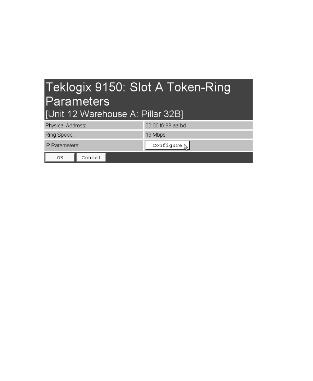
3.4.1.2 Slot n: Token-Ring
For the selection Slot n: Token-Ring, entering the “Configure” dialog box will open
the parameters page for the Token Ring connection, which shows the 9150’s physi-
cal (hardware) address, ring speed, and IP address parameters.
Physical Address
Each Madge Token Ring PC card has a unique MAC address (Physical Address),
which is displayed here in the 9150 parameters. The MAC address is presented in
standard hexadecimal format.
Ring Speed
This parameter indicates the Token Ring network speed. The ring speed must be set
through the console, prior to installation, using the configuration command line:
>cfg put interface.#.tokenring.datarate 16
(or 4 if the network is running at 4 Mbps)
The ‘#’ depends on which slot the PC card occupies. Usually this is slot B, inside the
9150, so the # would be 3. The default ring speed is 16 Mbps.
Teklogix 9150 Wireless Gateway User Manual 33
Chapter 3: 9150 Main Configuration
Interfaces
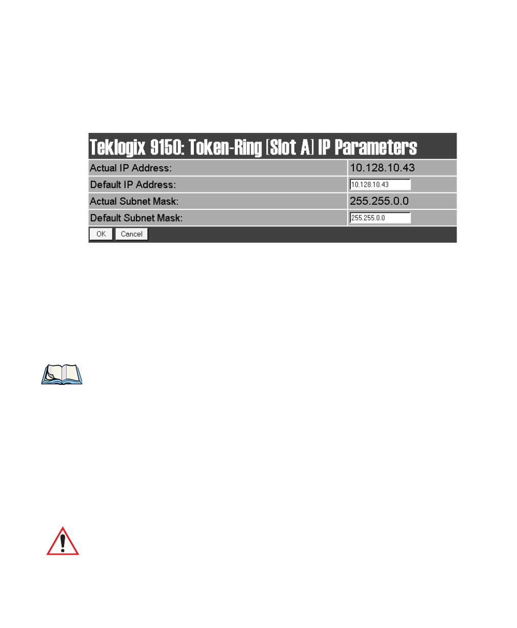
IP Parameters
Each 9150 that is connected to a local network has a unique IP address designated
for it. The IP Parameters used to assign the IP address are accessed by entering the
“Configure” dialog box.
Actual IP Address
The Actual IP Address is the IP address currently set on the 9150.
Default IP Address
This parameter allows you to change the value of the IP address. The IP address
must be a unique value on the network, including any Ethernet IP addresses being
used, so that each 9150 in your system can be identified. The acceptable value
ranges from 0.0.0.0 to 239.255.255.255.
Note: The value 255.255.255.255 is reserved for the broadcast address.
Actual Subnet Mask
The Actual Subnet Mask is the subnet mask currently set on the 9150.
Default Subnet Mask
This parameter allows you to change the value of the subnet mask. The 9150 uses
the Default Subnet Mask, its own IP address, and the destination IP address to deter-
mine if a packet should be sent on the local network or to a remote segment. If the
destination is found on the local network, the packet is sent directly to its destina-
tion. If the destination resides on a remote network, the packet is routed to the gate-
way. Enter your subnet mask in “xxx.xxx.xxx.xxx” notation.
Important: The maximum packet size supported is 1500 bytes. This parameter
is not set at the 9150, but should be set at the host.
Chapter 3: 9150 Main Configuration
Users
34 Teklogix 9150 Wireless Gateway User Manual
3.4.1.3 Slot n: PC Card Radio
Each PC (PCMCIA) card radio resident in the 9150 will be located in one of two
Slots: A or B. Selecting a PC card will open the sub-menu for that radio.
IEEE 802.11 FH or DS: See “IEEE 802.11 (Frequency Hopping Radio Parame-
ters)” on page 126, or “IEEE 802.11 (Direct Sequence Radio Parameters)” on page
128 for details on setting the radio parameters for the PC card.
TekLAN Card: See “TekLAN Parameters” on page 49 for details on setting the radio
and Wlan parameters.
Teklogix Narrowband: See “Narrow Band Radio Parameters” on page 53 for details
on setting the radio and polling parameters.
3.4.2 Users
The Users option provides security for access to the 9150 Configuration menus.
New individuals can be added by selecting “[#] Create New” in the listbox before
entering the “Configure” dialog box.
Individual names and their assigned passwords may be changed or deleted in the
“Configure” dialog box for this option by selecting the name in the listbox
and then opening the “Configure” dialog box. The password can be comprised of
alphanumeric characters and is case-sensitive.
Teklogix 9150 Wireless Gateway User Manual 35
Chapter 3: 9150 Main Configuration
SNMP
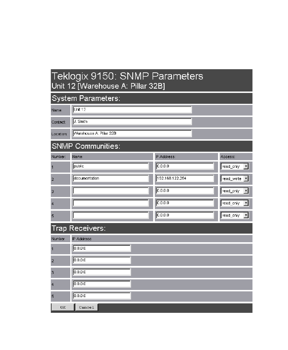
3.4.3 SNMP
The SNMP (Simple Network Management Protocol) “Configure” page allows
various network management parameters to be set or changed.

Chapter 3: 9150 Main Configuration
TCP/IP Parameters
36 Teklogix 9150 Wireless Gateway User Manual
3.4.3.1 System Parameters
The entries in these parameters set the name, contact and location identifiers for
this specific 9150 Wireless Gateway. The name and location are then shown as the
sub-heading of each Configuration page. In this example the identifier appears as
“Unit 12 [Warehouse A: Pillar 32B]”.
3.4.3.2 SNMP Communities
These parameter settings allow the network administrator to define the network
environment and determine the type of access allowed (read-only, or read-write) for
each area name and IP address.
3.4.3.3 Trap Receivers
These IP addresses determine which SNMP manager’s stations will receive SNMP
Traps from the 9150. The 9150 sends the “Cold Start” Trap on reboot or power up.
3.4.4 TCP/IP Parameters
The 9150 is situated on a wired network which uses TCP/IP. Both Bootp and DNS
options are available to resolve IP addressing issues.
Teklogix 9150 Wireless Gateway User Manual 37
Chapter 3: 9150 Main Configuration
TCP/IP Parameters
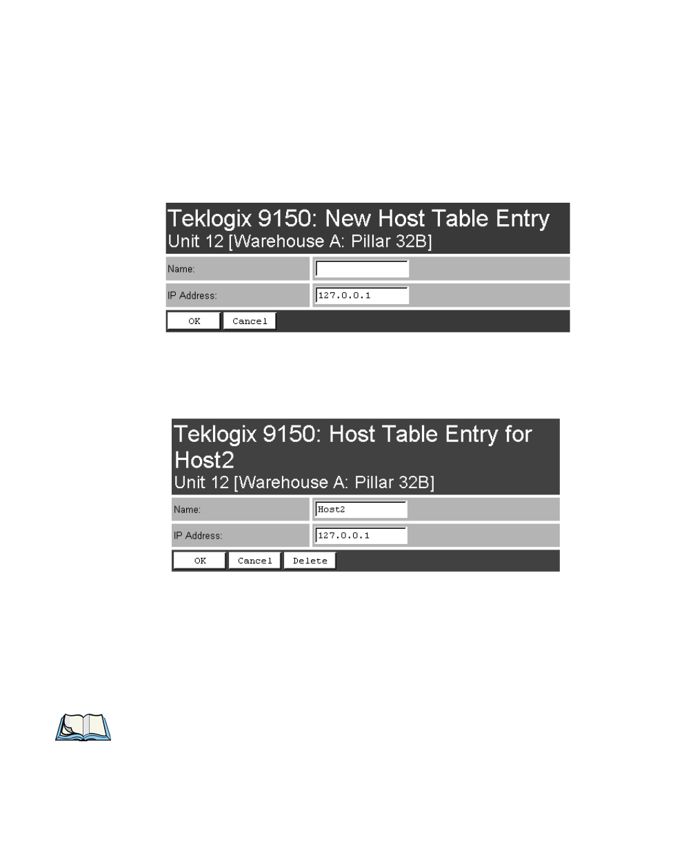
3.4.4.1 Host Table
If no external DNS server is available, the 9150 may resolve host names to IP
addresses using its internal host table. Hosts are added to the table by selecting
“Configure” beside “[#} Add Entry” in the listbox. This will open the New Host
Table Entry menu.
An existing host’s name and IP address may be edited in the Host Table Entry menu
by selecting “Configure” beside the host name in the listbox. The host may also be
deleted from the table.
Name
This is the designated name of the host.
IP Address
This is the assigned IP address for the host.
Note: The name must not contain space characters.
Chapter 3: 9150 Main Configuration
TCP/IP Parameters
38 Teklogix 9150 Wireless Gateway User Manual
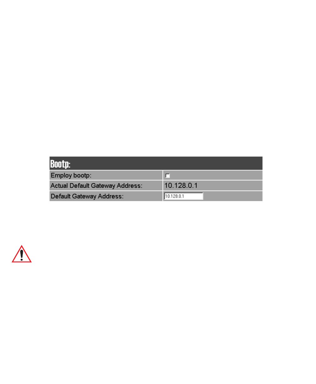
3.4.4.2 Bootp
The 9150 has designated default IP addresses for itself and the Gateway. Alterna-
tively, the IP address of the 9150 can be assigned using a BOOTP Server.
The primary purpose of the Bootstrap Protocol (BOOTP) is to assign a designated
IP address to the appropriate 9150 on the network. When Employ bootp is enabled,
a request for address is automatically broadcast to all hosts on the local network.
BOOTP Servers search the bootptab files for a hardware address which matches
that of the 9150 that initiated the request for address. (Bootptab files list each
hardware address with a corresponding IP address.) The host with a matching hard-
ware address in its bootp table replies to the request, sending the appropriate IP
address to the 9150.
Employ bootp
Enable Employ bootp (√), to automatically broadcast a request for address to all
hosts on the local network.
Important: Once the 9150 is configured and rebooted the first time, the Employ
bootp parameter should be disabled, unless the 9150 obtains its IP
address from a bootp server or the system administrator intends to
update the software through bootp.
Actual Default Gateway Address
This parameter shows the Default Gateway address currently set for the 9150.
Teklogix 9150 Wireless Gateway User Manual 39
Chapter 3: 9150 Main Configuration
TCP/IP Parameters
Default Gateway Address
The Default Gateway Address is assigned by the network administrator. This
address creates an identifiable communication link between the 9150 and a network
other than the one to which the 9150 is directly wired. The acceptable values for the
Gateway IP address range from 0.0.0.0 to 239.255.255.255.
Note: Setting the Gateway IP Address to 0.0.0.0 disables this feature.
A communication link will not exist between sub-networks.
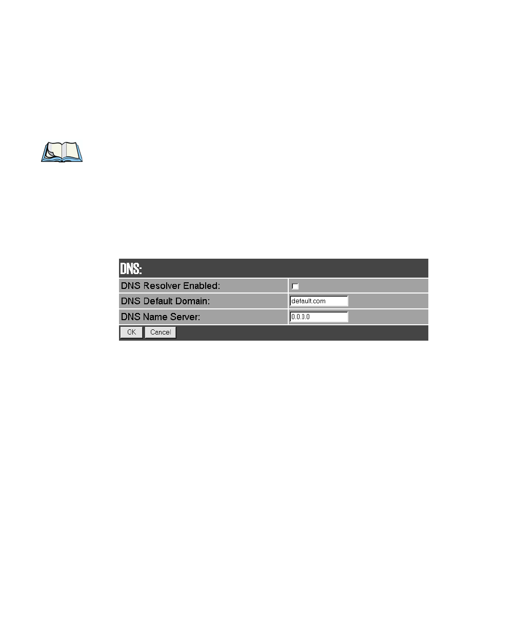
3.4.4.3 DNS
Domain Name System allows users to locate destinations on the TCP/IP network by
domain (host) name. The DNS server maintains a database of host names and their
corresponding IP addresses. For example, if the server was presented with the name
“www.teklogix.com”, it would return the IP address: “207.219.2.3”.
DNS Resolver Enabled
When this parameter is enabled (√), the 9150 will use the DNS Name Server identi-
fied by the IP address entered in the DNS Name Server parameter.
DNS Default Domain
This is the default domain name for this 9150.
DNS Name Server
This is the IP address of the designated DNS Name Server.

Chapter 3: 9150 Main Configuration
Serial Ports Parameters
40 Teklogix 9150 Wireless Gateway User Manual
3.4.5 Serial Ports Parameters
3.4.5.1 Console Port
The default baud rate for the console port is 19.2k.
3.4.5.2 Serial Port
The default baud rate for the serial port is 19.2k.
Teklogix 9150 Wireless Gateway User Manual 41
Chapter 3: 9150 Main Configuration
Access Point/Base Station Configurations
3.5 Access Point/Base Station Configurations
The 9150 is capable of operating as a transparent bridge (access point) between the
wireless and wired networks, and also as a mini-controller or base station. For these
operations, the parameters in these pages must be set appropriately. For detailed
information on the sub-menus and to set up the 9150 as a base station, see
Chapter 4: “Base Station Configuration”. To configure an access point device,
see Chapter 6: “Access Point Configuration”. To configure the 9150 as a mini-
controller, see Chapter 5: “Mini-Controller Configuration”.
.
Chapter 3: 9150 Main Configuration
Miscellaneous Commands
42 Teklogix 9150 Wireless Gateway User Manual
3.6 Miscellaneous Commands
There are two miscellaneous commands: System Info and Reboot Unit.
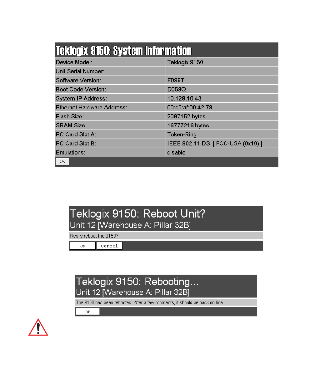
3.6.1 System Info
The System Information, hardware and software, for the 9150 Wireless Gateway
unit is detected automatically and summarized in this page. The screen is shown on
page 43.
Teklogix 9150 Wireless Gateway User Manual 43
Chapter 3: 9150 Main Configuration
Reboot Unit
3.6.2 Reboot Unit
This option opens a dialog box which allows you to remotely “warm” reboot
the 9150.
If the OK button is chosen, the 9150 will be rebooted, the LEDs will turn off
momentarily, and the following message will be received:
Important: If changing radio types in the 9150, and therefore changing the Radio
Type parameter (see page 50), the unit must be powered OFF and
ON again (“cold” rebooted). Rebooting with the Reboot Unit option
will not implement the radio parameter change.
