Contents
- 1. TRX7431 User Manual
- 2. Teklogix 9150 Wireless Gateway User Manual
- 3. Teklogix 9150 Wireless Gateway User Manual Declaration of Conformity
- 4. Teklogix 9150 Wireless Gateway User Manual Cautions to Users
- 5. Teklogix 9150 Wireless Gateway User Manual Teklogix Offices
- 6. Teklogix 9150 Wireless Gateway User Manual Table of Contents
- 7. Teklogix 9150 Wireless Gateway User Manual Chapter 1 Introduction
- 8. Teklogix 9150 Wireless Gateway User Manual Chapter 2 Installation Requirements
- 9. Teklogix 9150 Wireless Gateway User Manual Chapter 3 9150 Main Configuration
- 10. Teklogix 9150 Wireless Gateway User Manual Chapter 4 Base Station Configuration
- 11. Teklogix 9150 Wireless Gateway User Manual Chapter 5 Mini Controller Configurati
- 12. Teklogix 9150 Wireless Gateway User Manual Chapter 6 Access Point Configuration
- 13. Teklogix 9150 Wireless Gateway User Manual Chapter 7 Specifications
- 14. Teklogix 9150 Wireless Gateway User Manual Appendix A
- 15. Teklogix 9150 Wireless Gateway User Manual Appendix B
- 16. Teklogix 9150 Wireless Gateway User Manual Index
- 17. Teklogix 9150 Wireless Gateway User Manual Appendix A
- 18. 7035 8255 8260 User Manual
- 19. 9150 User Manual
- 20. response to FCC correspondence 15472
7035 8255 8260 User Manual

7035, 8255 & 8260
Terminals
User Manual
March 9, 2000 Part No. 80439.C
© Copyright 2000 by Teklogix Inc., Mississauga, Ontario
This document and the information it contains is the property of Teklogix Inc., is
issued in strict confidence, and is not to be reproduced or copied, in whole or in part,
except for the sole purpose of promoting the sale of Teklogix manufactured goods
and services. Furthermore, this document is not to be used as a basis for design,
manufacture, or sub-contract, or in any manner detrimental to the interests of
Teklogix Inc.
All trademarks are the property of their respective holders.
Return-To-Factory Warranty
Teklogix warrants a return-to-factory warranty for a period of 90 days from shipment
or 120 days from shipment where Teklogix installs the equipment. The warranty on
Teklogix manufactured equipment does not extend to any product that has been
tampered with, altered, or repaired by any person other than an employee of an
authorized Teklogix service organization. See Teklogix terms and conditions of sale
for full details.
Service
When requesting service, please provide information concerning the nature of the
failure and the manner in which the equipment was used when the failure occurred.
Type, model, and serial number should also be provided. Before returning any
products to the factory, call the Service Centre in your region for a Return
Authorization number. This will help us to service your product more efficiently.
Disclaimer
Every effort has been made to make this material complete, accurate and up-to-date.
Teklogix Inc. reserves the right to make changes without notice and shall not be
held responsible for damages resulting from reliance on the material presented
in this manual.

Declaration Of Conformity
Product: 7035 Hand-Held Terminal
Application of Council EMC Directive: 89/336/EEC
Directive(s):
Conformity Declared EN 55022: 1994; Class B; ETS 300 328: 1996
to Standards: EN 50082-1: 1997; ETS 300 683: 1997, ETS 300 826: 1997
EN 61000-4-2; ±4 kV CD; ±8 kV AD
EN 61000-4-3; 3 V/m, 80-1000 MHz
Manufacturer: Teklogix Incorporated
2100 Meadowvale Boulevard
Mississauga, Ontario
Canada
L5N 7J9
Year of Manufacture: 1999
Manufacturer’s Address Teklogix S.A.
in the European Parc Club Du Golf - Bat 1.
Community: 13856 Aix-En-Provence
Cedex 3; France
Type of Equipment: Information Technology Equipment
Equipment Class: Commercial and Light Industrial

Declaration Of Conformity
Product: 8255 Vehicle-Mount Terminal
Application of Council EMC Directive: 89/336/EEC
Directive(s): Low Voltage Directive: 73/23/EEC
Conformity Declared EN 55022: 1998; Class B; ETS 300 826: 1997
to Standards: EN 50082-1: 1997; ETS 300 683: 1997
EN 61000-4-2; ±4 kV CD; ±8 kV AD
EN 61000-4-3; 3 V/m, 80-1000 MHz
ISO 7637-1: 1990
ISO 7637-2: 1990
EN 60950: 1992 + A1 + A2 + A3 + A4 + A11
Manufacturer: Teklogix Incorporated
2100 Meadowvale Blvd.
Mississauga, Ontario
Canada
L5N 7J9
Year of Manufacture: 1999
Manufacturer’s Address Teklogix S.A.
in European Community: Parc Club Du Golf - Bat 1.
13856 Aix-En-Provence
Cedex 3; France
Type of Equipment: Information Technology
Equipment Class: Commercial and Light Industrial

Declaration Of Conformity
Product: 8255 LCD Vehicle-Mount Terminal
Application of Council EMC Directive: 89/336/EEC
Directive(s): Low Voltage Directive: 73/23/EEC
Conformity Declared EN 55022: 1998; Class B; ETS 300 826: 1997
to Standards: EN 50082-1: 1997; ETS 300 683: 1997
EN 61000-4-2; ±4 kV CD; ±8 kV AD
EN 61000-4-3; 3 V/m, 80-1000 MHz
ISO 7637-1: 1990
ISO 7637-2: 1990
EN 60950: 1992 + A1 + A2 + A3 + A4 + A11
Manufacturer: Teklogix Incorporated
2100 Meadowvale Blvd.
Mississauga, Ontario
Canada
L5N 7J9
Year of Manufacture: 1999
Manufacturer’s Address Teklogix S.A.
in European Community: Parc Club Du Golf - Bat 1.
13856 Aix-En-Provence
Cedex 3; France
Type of Equipment: Information Technology
Equipment Class: Commercial and Light Industrial

Declaration Of Conformity
Product: 8260 Vehicle-Mount Terminal
Application of Council EMC Directive: 89/336/EEC
Directive(s): Low Voltage Directive: 73/23/EEC
Conformity Declared EN 55022: 1998; Class B; ETS 300 826: 1997
to Standards: EN 50082-1: 1997; ETS 300 683: 1997
EN 61000-4-2; ±4 kV CD; ±8 kV AD
EN 61000-4-3; 3 V/m, 80-1000 MHz
ISO 7637-1: 1990
ISO 7637-2: 1990
EN 60950: 1992 + A1 + A2 + A3 + A4 + A11
Manufacturer: Teklogix Incorporated
2100 Meadowvale Blvd.
Mississauga, Ontario
Canada
L5N 7J9
Year of Manufacture: 1999
Manufacturer’s Address Teklogix S.A.
in European Community: Parc Club Du Golf - Bat 1.
13856 Aix-En-Provence
Cedex 3; France
Type of Equipment: Information Technology
Equipment Class: Commercial and Light Industrial

Teklogix 7035, 8255 & 8260 Terminals User Manual
i
T
ABLE
OF
C
ONTENTS
Program License Agreement
.............................ix
Safety Summary
.....................................xi
Chapter 1: Introduction
1.1 About This Manual ............................3
1.2 Text Conventions .............................4
1.3 About The Terminals ...........................5
1.3.1 Features ............................5
1.3.2 The 7035 Hand-Held Terminal ................7
1.3.3 7035 Integrated Scanner Patent Numbers ...........11
1.3.4 The 8255 Vehicle-Mount Terminal – LCD or VFD .....11
1.3.5 The 8260 Vehicle-Mount Terminal - LCD Only .......12
Chapter 2: Basic Assembly And Operation
2.1 Preparing The 7035 For Operation ....................17
2.1.1 Connecting The 7035 Whip Antenna .............17
2.1.2 The Battery Pack – Removing And Installing.........17
2.1.3 Attaching The 7035 Hand-Strap Or The Pistol Grip .....19
2.2 Installing 8255/8260 Vehicle-Mount Terminals..............20
2.2.1 Mounting The 8255 Vehicle-Mount Terminal ........20
2.2.2 Using The Cradle And Cradle Mounting Plate ........21
2.2.3 Mounting The 8260 Terminal .................23
2.2.4 Connecting The 8255/8260 Antenna .............24
2.2.5 Installing The Cables .....................24
2.2.6 Installing The Extension Power Cable ............25
2.3 Basic Operation Of The Terminals ....................26
2.3.1 Turning The Terminals On And Off .............26
2.3.2 Resetting Terminals ......................27
Contents
ii
Teklogix 7035, 8255 & 8260 Terminals User Manual
2.3.3 The Display Menu ......................28
2.3.4 The Keyboard ........................30
2.4 The Indicators ..............................39
2.4.1 LEDs .............................39
2.4.2 Onscreen Indicators – 7035 Only ..............40
2.4.3 Softkeys ...........................42
2.4.4 The Battery Gauge (7035 Only) ...............42
2.4.5 The Beeper ..........................42
2.5 The Display ...............................44
2.5.1 Adjusting The Display Contrast ...............44
2.5.2 Panning ............................45
2.6 The Integrated Scanner Option – 7035 Only ..............46
2.6.1 Warnings ...........................46
2.6.2 Operation Of The Integrated Scanner ............46
2.6.3 Scanning Techniques.....................48
2.7 Infrared (IrDA) Port – 7035 Only ....................48
2.8 Maintenance ...............................48
2.8.1 Cleaning All Terminals ...................48
2.8.2 7035 – Special Instructions..................49
2.8.3 Maintaining The 7035 Battery ................49
Chapter 3: Tekterm
3.1 Introduction ...............................53
3.2 Launching Tekterm ...........................53
3.3 Working With Application Session Windows ..............54
3.4 Radio Statistics Screens .........................54
3.4.1 Viewing A Radio Statistics Screen..............54
3.4.2 802.11 Radio Statistics Screen ................55
3.4.3 TRX7370 NB & 802.11 SS Radio Statistics Screen.....56
3.4.4 TRX7460 Mobitex WAN Radio Statistics Screen......57
3.5 Resetting Radio Statistics ........................60
3.6 Exiting Tekterm .............................60
Chapter 4: TESS Operations
4.1 Configuration ..............................63
4.2 Working With Multiple Sessions ....................63
Teklogix 7035, 8255 & 8260 Terminals User Manual
iii
Contents
4.3 The Field Types ..............................64
4.4 Data Entry .................................64
4.4.1 TESS Edit Modes And Cursor Movement ..........65
4.4.2 <CLR> Key Behaviour In TESS ...............66
4.4.3 <DEL> Key Behaviour In TESS ...............67
4.5 Lock Messages ..............................69
4.6 Control Commands ............................69
Chapter 5: ANSI Operations
5.1 Configuration ...............................73
5.2 Sending Data To The Host ........................73
5.3 Teklogix Keyboard And VT220 Equivalent Keys.............74
5.4 Working With Sessions ..........................75
5.4.1 Establishing A New Session..................75
5.4.2 Listing Sessions And Moving To Other Sessions.......75
5.4.3 Closing A Session .......................76
5.4.4 Printing A Screen .......................76
5.4.5 Smart Echo – Disabling ....................76
Chapter 6: Setting Parameters
6.1 Using The Parameter Manager ......................81
6.2 Exiting Tekterm And Accessing The Display Menu ...........81
6.3 Working With Menus ...........................83
6.3.1 Softkey Function Keys ....................83
6.3.2 Displaying Sub-Menus ....................84
6.3.3 Numeric Parameters ......................84
6.3.4 Y/N Parameters ........................85
6.3.5 Alpha Parameters .......................85
6.3.6 String Entry Parameters ....................85
6.3.7 Saving Changes To Parameters ................87
6.3.8 Resetting The Terminal ....................87
6.3.9 Resetting Parameters To Default Values ...........87
6.4 Terminal Parameters............................88
6.4.1 Displaying The Parameters Menu ...............88
6.5 System...................................90
6.5.1 Volume And Contrast .....................90
Contents
iv
Teklogix 7035, 8255 & 8260 Terminals User Manual
6.5.2 Key Click...........................91
6.5.3 Typematic Rpt ........................91
6.5.4 Panning ............................92
6.5.5 Backlight ...........................94
6.5.6 Code Page ..........................95
6.5.7 Font Size – North American And European .........96
6.5.8 Font Size – Chinese And Korean ..............97
6.5.9 Palette Remap ........................98
6.5.10 Watchdog Timer .......................99
6.5.11 Power – 7035 Only......................99
6.5.12 One-Shot Mode .......................100
6.6 Scanner..................................101
6.6.1 Type .............................101
6.6.2 Options ............................102
6.6.3 Barcode............................105
6.7 Applications ...............................115
6.7.1 ANSI Settings ........................116
6.7.2 Serial .............................126
6.7.3 TESS Settings ........................126
6.7.4 Features............................138
6.8 View Manager ..............................139
6.9 Ports– Serial 1 And Console 2 ......................141
6.9.1 Serial 1 And Console 2 Peripheral Options .........141
6.9.2 Serial 1 And Console 2 Parameter Settings .........142
6.9.3 Setting The Terminal Console Port For Nomad .......144
6.9.4 Setting The Terminal Console Port For Scan-See ......144
6.10 Global Macros ..............................150
6.10.1 Displaying The Global Macros Menu ............150
6.10.2 Displaying The Global Macros Table ............151
6.10.3 Choosing An ASCII Character................152
6.10.4 Adding Additional ASCII Characters ............152
6.10.5 Programming Special Keys Into Macros...........153
6.11 Network .................................153
6.12 Radio ...................................154
6.13 Sound ..................................154
Teklogix 7035, 8255 & 8260 Terminals User Manual
v
Contents
Chapter 7: Terminal Accessories
7.1 External Bar Code Readers .......................159
7.1.1 Entering Data With A Bar Code Reader ..........159
7.2 The 7035 Battery ............................160
7.2.1 Lithium-Ion Battery Safety Precautions...........161
7.2.2 Lithium-Ion Battery Pack Specifications ..........162
7.3 The 7942 In-Unit Charger........................163
7.3.1 Mounting Bracket ......................164
7.3.2 Connecting The Power Source ...............164
7.3.3 In-Unit Charger LED Indicators...............164
7.3.4 Inserting The 7035 With Battery In The Charger ......165
7.3.5 Charging The Battery ....................165
7.3.6 Battery Charge Fault Conditions ..............165
7.3.7 Charger Fault Conditions ..................166
7.3.8 Removing The Terminal From The In-Unit Charger ....166
7.3.9 7942 Charger Specifications.................166
7.4 The 7967 Gang Charger.........................167
7.4.1 Connecting The Power Source ...............167
7.4.2 Inserting And Charging The Battery ............167
7.4.3 Fault Conditions .......................168
7.4.4 7967 Charger Specifications.................169
7.5 Important Charger Safety Instructions .................169
7.6 Antenna Types..............................170
7.7 The 7035 Picker Cradle .........................171
7.7.1 Mounting Hardware .....................171
7.7.2 Installation ..........................171
7.7.3 Disassembling The Cradle Before Mounting ........172
7.7.4 Mounting The Cradle ....................173
7.7.5 Installing The Cables ....................173
7.7.6 Connecting A Cable .....................173
7.7.7 Connecting The Power Source ...............174
7.7.8 Attaching A Port Replicator .................174
7.7.9 Picker Cradle Maintenance .................174
7.7.10 Inserting And Removing The 7035 Terminal ........175
7.7.11 Picker Cradle LED Indicator ................176
Contents
vi
Teklogix 7035, 8255 & 8260 Terminals User Manual
7.7.12 Specifications.........................177
7.8 Accessories Part Number List ......................179
Chapter 8: Specifications
8.1 Radio Specifications ...........................183
8.2 7035 Hand-Held Terminal Specifications ................186
8.3 8255/8260 Vehicle-Mount Terminal Specifications ...........188
8.4 Peripheral Ports .............................191
8.4.1 Serial Port 1 (COM 1) ....................191
8.4.2 Serial Port 2 (COM 2) ....................191
8.5 Memory Expansion Board........................192
8.6 IrDA Port (7035 Only)..........................192
8.7 Wireless Communication Options ....................192
8.8 Bar Code Scanning............................193
8.8.1 Internal Scanners (7035 Only) ................193
8.8.2 External Scanners ......................193
8.8.3 Internal Scanner Port (7035 Only) ..............193
8.9 Internal Scanner Specifications (7035 Only) ..............194
8.10 Power Management (7035 Only) ....................197
8.10.1 Power Save States ......................197
8.11 Lithium-Ion Battery Pack (7035 Only) .................199
Appendices
Appendix A: Support Services And Worldwide Offices
A.1 Support Services .............................A-1
A.1.1 North American Helpdesk ..................A-1
A.1.2 International Support .....................A-1
Appendices
Appendix B: Port Pinouts And Cable Diagrams
B.1 7035 Peripheral Port I/O Connector
(28-Pin PCR)
...........B-1
B.2 8255/60 Peripheral Port I/O Connector
(28-Pin PCR)
..........B-2
B.3 8255/60 - Expansion Port I/O Connector (36-Pin PCR).........B-4
Teklogix 7035, 8255 & 8260 Terminals User Manual
vii
Contents
B.4 Internal Scanner Connector .......................B-6
B.5 Flash Serial Download Cable ......................B-6
B.6 28-Pin PCR To 8-Pin DIN Connector – P.N. 19726 ..........B-7
B.7 28-Pin PCR To 7-Pin DIN Connector – P.N. 19727 ..........B-7
B.8 Flash Serial Download Cable – P.N. 20075...............B-8
B.9 Scanner Wand Adaptor Cable – P.N. 30092...............B-8
Appendix C: ASCII Character Table
Appendix D: Radio Parameters
D.1 TRX7430 WaveLAN/IEEE 802.11 DS SS Radio Parameters .....D-1
D.2 TRX7440 RangeLAN 802.11 FH SS Radio Parameters ........D-4
D.3 TRX7370 Narrow Band Radio Parameters ...............D-6
D.3.1 Cellular ...........................D-6
D.3.2 Channel ...........................D-7
D.3.3 Poll Timing .........................D-9
D.3.4 Power Saving .......................D-11
D.3.5 CIS Data ..........................D-11
D.4 TRX7410/10A WLAN 902 Spread Spec Radio Parameters .....D-12
D.4.1 Channel ..........................D-12
D.4.2 WLAN Timing.......................D-14
D.4.3 Power Saving .......................D-14
D.4.4 CIS Data ..........................D-15
D.5 TRX7460 Mobitex Radio .......................D-15

Teklogix 7035, 8255 & 8260 Terminals User Manual
ix
P
ROGRAM
L
ICENSE
A
GREEMENT
These products contains proprietary information of Teklogix Inc. as well as the
following companies: International Business Machines Corporation, Phoenix
Technologies Limited, Datalight, Inc.
1
and Pacific Softworks Incorporated.
Software restrictions are as follows and shall be enforced to the fullest extent possi-
ble by applicable law:
i. copying and/or transfer of the software is prohibited; and
ii. reverse assembly, reverse compilation, or other translation of the
software is prohibited; and
iii. software is copyrighted and licensed (not sold) and that title to the
software is not transferred; and
iv. the owner of the software “DISCLAIMS ALL WARRANTIES
WITH RESPECT TO THE USE OF THE SOFTWARE
INCLUDING (WITHOUT LIMITATION) ANY WARRANTIES
OF MERCHANTABILITY OR FITNESS FOR A PARTICULAR
PURPOSE; and
v. liability is limited to the amount paid by the end user for the software;
and
vi. the use of the software is allowed only in conjunction with products
described herein.
1
Datalight is a registered trademark of Datalight, Inc. FlashFX™ is a trademark of Datalight,
Inc. Copyright 1993-1999 Datalight, Inc., All Rights Reserved.
Teklogix 7035, 8255 & 8260 Terminals User Manual
xi
S
AFETY
S
UMMARY
This safety information is for the protection of both operating and service personnel.
This equipment complies with Class B, Part 15 of the FCC rules. Operation is
subject to the following two conditions:
1) This device may not cause harmful interference, and
2) This device must accept any interference received, including interference that
may cause undesired operation.
Changes or modifications not expressly approved by the party responsible for
compliance could void the user’s authority to operate the equipment.
For sites in Canada, Teklogix TRX7430 and TRX7440 802.11 radios require a radio
licence unless they are installed totally within a building (user shall obtain licence
from Industry Canada).
Use only Teklogix approved peripheral devices and cables.
RF E
XPOSURE
R
EQUIREMENTS
To satisfy FCC RF exposure requirements for mobile transmitting devices,
a separation distance of 20 cm or more should be maintained between the
antenna of this device and persons during device operation. To ensure com-
pliance, operation at closer than this distance is not recommended.
D
O
N
OT
O
PERATE
I
N
A
N
E
XPLOSIVE
A
TMOSPHERE
Operating Teklogix equipment where explosive gas is present may result in
an explosion.
D
O NOT REMOVE COVERS OR OPEN ENCLOSURES
To avoid injury, the equipment covers and enclosures should only be
removed by qualified service personnel. Do not operate the equipment
without the covers and enclosures properly installed.

Safety Summary
xii Teklogix 7035, 8255 & 8260 Terminals User Manual
DO NOT HOLD ANTENNA
To avoid discomfort due to the local heating effect of Radio Frequency
energy, do not touch the antenna when a terminal is transmitting.
USE PROPER FUSE
For vehicle-mount terminals, use only the fuses specified. A replacement
fuse must meet the type, voltage rating and current rating for the fuse it
replaces or a fire may result.
CAUTION!
Danger of explosion if a 7035 battery is incorrectly handled, charged,
disposed of or replaced. Replace only with the same or equivalent type
recommended by the manufacturer. Dispose of used batteries according to
the instructions described in “Maintaining The 7035 Battery” on page 49.
Carefully review all battery safety issues listed in the section titled “Lith-
ium-Ion Battery Safety Precautions” on page 161 and page 162.
VORSICHT!
Explosiongefahr bei unsachgemäßem Austausch der Batterie Ersatz nur
durch denselben oder einen vom Hersteller empfohlenen gleichwertigen
Typ. Entsorgung gebrauchter Batterien nach Angaben des Herstellers.

Teklogix 7035, 8255 & 8260 Terminals User Manual 1
INTRODUCTION 1
1
1.1 About This Manual ...............................3
1.2 Text Conventions ................................4
1.3 About The Terminals ..............................5
1.3.1 Features .................................5
1.3.2 The 7035 Hand-Held Terminal .....................7
1.3.3 7035 Integrated Scanner Patent Numbers ................11
1.3.4 The 8255 Vehicle-Mount Terminal – LCD or VFD ...........11
1.3.5 The 8260 Vehicle-Mount Terminal - LCD Only.............12
Teklogix 7035, 8255 & 8260 Terminals User Manual 3
Chapter 1: Introduction
About This Manual
1.1 About This Manual
This manual describes how to operate the Teklogix 7035, 8255 and 8260 terminals.
Chapter 1: Introduction
provides a basic overview of the 7035 hand-held terminal and the 8255 and
8260 vehicle-mount terminals.
Chapter 2: Basic Assembly And Operation
explains how to attach an antenna, how to work with internal and external
power supplies and how to mount vehicle-mount terminals. It also describes the
LEDs, beeper and display.
Chapter 3: Tekterm
describes how to work with application sessions within the Tekterm program.
Chapter 4: TESS Operations
describes editing modes, status messages and control commands for
TESS operations.
Chapter 5: ANSI Operations
provides information about function key equivalents and data entry for
ANSI operations.
Chapter 6: Setting Parameters
lists and defines the terminal parameters.
Chapter 7: Terminal Accessories
provides information about using barcode readers and other accessories such as
the AC power adaptor, battery chargers, and so on.
Chapter 8: Specifications
contains the technical specifications for the terminal, the battery charger and the
COM ports.
Appendix B: Port Pinouts And Cable Diagrams
includes pinouts and diagrams of the ports and cables.
Appendix C: ASCII Character Table
provides a table of ASCII characters.
Appendix D: Radio Parameters
describes the parameters for the TRX7370 Narrowband radio, the TRX7430
Lucent WaveLAN II IEEE 802.11 PC Card and the TRX7440 Proxim
RangeLAN 802 8400 PC Card and the TRX7410/TRX7410A 902 SS PC card.

Chapter 1: Introduction
Text Conventions
4Teklogix 7035, 8255 & 8260 Terminals User Manual
1.2 Text Conventions
Note: Notes highlight additional helpful information.
Important: These statements provide particularly important instructions
or additional information that is critical to the operation of
the equipment.
Warning: These statements provide critical information that may prevent
physical injury, equipment damage or data loss.
Teklogix 7035, 8255 & 8260 Terminals User Manual 5
Chapter 1: Introduction
About The Terminals
1.3 About The Terminals
The 7035 hand-held terminal and the 8255 and 8260 vehicle-mount RF terminals all
run DOS and can operate in a Teklogix narrowband or 902 spread spectrum RF
system using the “cellular” or “new” protocol. They can also operated in a 2.4 GHz
802.11 system.
1.3.1 Features
Some features of these terminals include:
• 7035s are equipped with 33 MHz 486DX CPU with internal cache.
• 8255 and 8260 vehicle-mount terminals are equipped with 66 MHz 486DX
CPU with internal cache.
• 8 MB RAM – can be expanded to 16 MB.
• 4 MB of Flash ROM – can be expanded to 8 MB.
• RF connectivity options include:
- IEEE 802.11 2.4 GHz frequency hopping and direct sequence PC card
radios (1-2 Mbps) (TRX7430), (TRX7440).
- TRX7370 Narrowband PC card-based radios (403-512 MHz, 4800-
19200 bps).
- TRX7410 TekLan 902 MHz direct sequence spread spectrum radios.
• 7035 terminal can support a standard external or optional internal antenna.
(Note that the internal antenna is only available with certain 802.11 radios.)
• 8255 and 8260 vehicle-mount terminals are shipped with external antennas
that are compatible with the operating RF system.
• Rugged, sealed enclosure, suitable for industrial environments.
• Seamless operation on all Teklogix 32-bit narrowband RF backbones:
- ANSI, TESS (IBM 3270, IBM5250 and HP2392) emulation
application built in.
- uses high performance TRX7370 narrowband radio.
• Embedded DOS.
• Ergonomic design:
- 7035 offers one-handed “scan & confirm” design
- all terminals provide high visibility display fonts and low impact keys.
Chapter 1: Introduction
Features
6Teklogix 7035, 8255 & 8260 Terminals User Manual
- full alphanumeric keyboard.
- keyboard can be customized using overlays, soft-label function keys
and macro keys.
- vehicle-mount terminals can be ordered with a QWERTY, an ABC or
an AZERTY keyboard.
- autopanning in text mode.
- 7035 status screen area displays system information – battery gauge,
RF link status and shift indicators – as the application is running.
- vehicle-mounts are equipped with a special set of LEDs that act as
shift indicators, blinking when a key is active and staying on when a
key is locked “on”.
- softkey labels are displayed at the bottom of all terminal screens,
indicating the function of function keys <F1> to <F4> on the 7035 –
<F1> to <F6> on vehicle-mounts.
• Two internal PC Card Type II slots:
- one slot is reserved for the terminal radio.
- the extra slot can be used for any PC Card Type II Flash disk, adding
from 16 to 128 MB of additional mass storage that appears as an
additional drive. (Note that this slot is not available if the terminal is
operating with a TRX7370 narrowband or a TRX7410 TekLan 902
spread spectrum radio.)
• RS-232 peripheral port supports decoded and non-decoded scanners, serial
printers and COM devices.
• Macro keys to program special characters, keys and/or frequently-used
key strokes.

Teklogix 7035, 8255 & 8260 Terminals User Manual 7
Chapter 1: Introduction
The 7035 Hand-Held Terminal
1.3.2 The 7035 Hand-Held Terminal
Figure 1.1 The 7035 Hand-Held

Chapter 1: Introduction
The 7035 Hand-Held Terminal
8Teklogix 7035, 8255 & 8260 Terminals User Manual
Figure 1.2 7035-I With Optional Pistol Grip Handle

Teklogix 7035, 8255 & 8260 Terminals User Manual 9
Chapter 1: Introduction
The 7035 Hand-Held Terminal
Figure 1.3 7035 Peripheral Port
Figure 1.4 Infrared (IrDA) Port
Warning: Using controls or adjustments or performing procedures other than
those specified herein may result in hazardous radiation exposure.
IrDA Port
Integrated Scanner

Chapter 1: Introduction
The 7035 Hand-Held Terminal
10 Teklogix 7035, 8255 & 8260 Terminals User Manual
Figure 1.5 Safety Labels
LITHIUM-ION RECHARGEABLE
BATTERY 7.2 V, 1350mAh
ASSEMBLED IN JAPAN
BURN HAZARD, DO NOT INCINERATE
OR HEAT ABOVE 100˚C (212F)
DO NOT DISASSEMBLE
NOT FOR USE BELOW -20˚C (-4F)
RECYCLE OR DISPOSE OF
PROPERLY
WARNING!
20605
20597A
Mississauga, Ont.
Canada, L5N 7J9
U.S. PAT. 4,758,717
Model 7035 Handheld
Serial No.:
Manufactured:
Ref No.:
Made in
Canada
This device complies with 21 CFR 1040.10
This device complies with part 15 of the FCC Rules.
Operation is subject to the following two conditions:
(1) This device may not cause harmful interference, and
(2) this device must accept any interference received,in-
cluding interference that may cause undesired operation.
CANADA: XXX XXX XXX
FCC ID: XXXXXX - XX
This product contains
XXXXXX 2.4 GHz Radio
XXXXX XXX - XX
PN: XXX-XXXXXX-XX
CAUTION
DO NOT STARE INTO BEAM
630-680nm LASER DIODE
1.0 MILLIWATT MAX.OUTPUT
CLASS II LASER PRODUCT
LASER RADIATION
SEE BATTERY COMPARTMENT FOR MANUFACTURING DATA.
20599-001
A
C
B
of the battery.
This label is affixed to the underside
• Serial Number
• Reference Number. This field contains
• Manufactured. This field contains the terminal's
a numeric code used to identify the
date of manufacture.
country code, the temperature range
of the terminal, and so on.
This label lists the following:
B. Lithium-Ion Battery Warning Label
A. Laser Radiation Warning Label
C. Model/Serial Number Label
Teklogix 7035, 8255 & 8260 Terminals User Manual 11
Chapter 1: Introduction
7035 Integrated Scanner Patent Numbers
1.3.3 7035 Integrated Scanner Patent Numbers
The integrated scanner used in the 7035 may be covered by one or more of the
following U.S. patents:
4,360,798; 4,369,361; 4,387,297; 4,460,120; 4,496,831; 4,593,186; 4,603.262; 4,607,156; 4,652,750;
4,673,805; 4,736,095; 4,758,717; 4,816,660; 4,845,350; 4,896,026; 4,897,532; 4,923,281; 4,933,538;
4,992,717; 5,015,833; 5,017,765; 5,021,641; 5,029,183; 5,047, 617; 5,103,461; 5,113,445; 5,130,520;
5,140,144; 5,142,550; 5,149,950; 5,157,687; 5,168,148; 5,168,149; 5,180,904; 5,229,591; 5,230,088;
5,235,167; 5,243,655; 5,247,162; 5,250,791; 5,250,792; 5,262,627; 5,280,163; 5,280,164; 5,280,498;
5,304,786; 5,304,788; 5,321,246; 5,367,151; 5,373,148; 5,378.882; 5,377,361; 5,396,053; 5,396,055;
5,399,846; 5,408,081; 5,410,139; 5,410,140; 5,412,198; 5,418,812; 5,420,411; 5,436,440; 5,444,231;
5,449,891; 5,449,893; 5,468,949; 5,479,000; 5,479,002; 5,479,441; 5,504,322; 5,528,621; 5,532,469;
5,543,610; 5,545,889; 5,552,592; 5,578,810; 5,589,680;D305,885; D341,584; D344,501; D359,483;
D362,435; D363,700; D363,918; D370,478.
Invention No. 55,358; 62,539; 69,060; 69,187 (Taiwan); No: 1,601,796; 1,907,875; 1,955,269 (Japan).
European Patent 367,299; 414,281; 367,300; 367,298; UK 2,072,832; France 81/03938;
Italy 1,138,713.
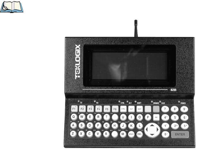
1.3.4 The 8255 Vehicle-Mount Terminal – LCD or VFD
Note: The 8255 terminal is available with a liquid crystal display (LCD) or a
vacuum fluorescent display (VFD).
Figure 1.6 The 8255 Vehicle-Mount
Chapter 1: Introduction
The 8260 Vehicle-Mount Terminal - LCD Only
12 Teklogix 7035, 8255 & 8260 Terminals User Manual
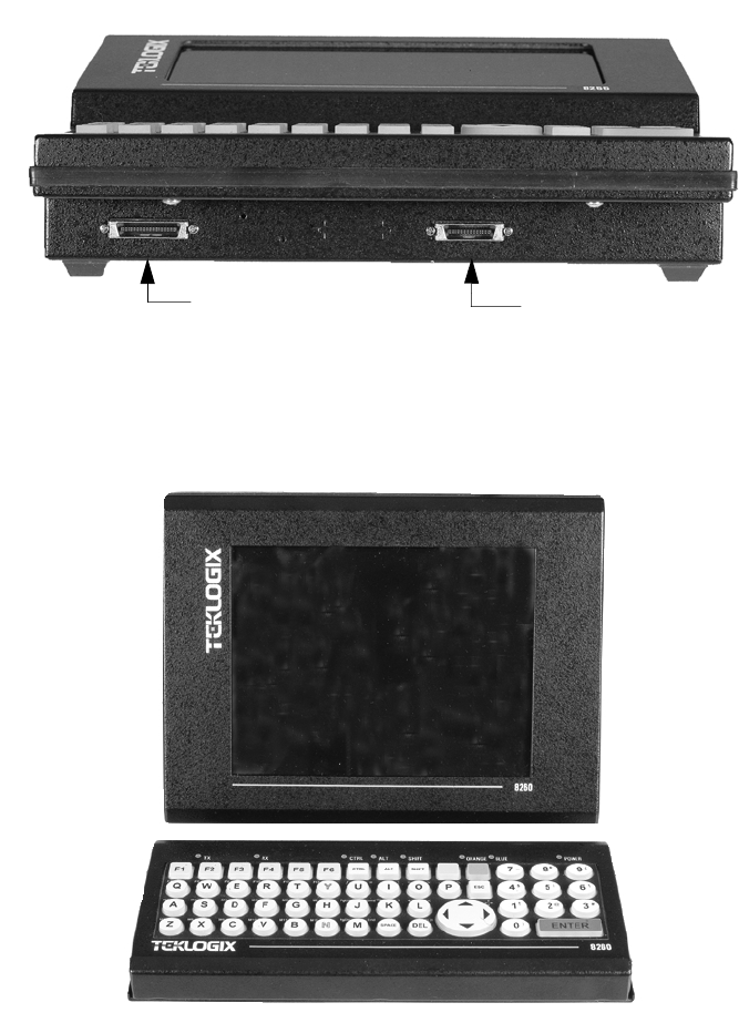
Figure 1.7 8255 Ports
1.3.5 The 8260 Vehicle-Mount Terminal - LCD Only
Figure 1.8 The 8260 Vehicle-Mount
Scanner Port
Expansion Port

Teklogix 7035, 8255 & 8260 Terminals User Manual 13
Chapter 1: Introduction
The 8260 Vehicle-Mount Terminal - LCD Only
Figure 1.9 8260 Ports
Expansion
Port
Keyboard
Connector
Scanner
Port

Teklogix 7035, 8255 & 8260 Terminals User Manual 15
BASIC ASSEMBLY AND OPERATION 2
2
2.1 Preparing The 7035 For Operation .......................17
2.1.1 Connecting The 7035 Whip Antenna ..................17
2.1.2 The Battery Pack – Removing And Installing ..............17
2.1.3 Attaching The 7035 Hand-Strap Or The Pistol Grip...........19
2.1.3.1 Attaching The Hand Strap ...................19
2.1.3.2 Attaching The Pistol Grip....................19
2.2 Installing 8255/8260 Vehicle-Mount Terminals ................20
2.2.1 Mounting The 8255 Vehicle-Mount Terminal ..............20
2.2.2 Using The Cradle And Cradle Mounting Plate .............21
2.2.3 Mounting The 8260 Terminal ......................23
2.2.4 Connecting The 8255/8260 Antenna...................24
2.2.5 Installing The Cables...........................24
2.2.6 Installing The Extension Power Cable..................25
2.3 Basic Operation Of The Terminals .......................26
2.3.1 Turning The Terminals On And Off ...................26
2.3.1.1 7035 Hand-Held ........................26
2.3.1.2 8255 And 8260 Vehicle-Mounts ................27
2.3.2 Resetting Terminals ...........................27
2.3.2.1 Resetting The 7035 .......................27
2.3.2.2 Resetting The 8255 And 8260 .................27
2.3.3 The Display Menu ............................28
2.3.3.1 Bypassing Tekterm At Terminal Bootup ............28
2.3.3.2 Launching And Exiting The Parameters Menu.........28
2.3.3.3 Launching And Exiting Tekterm ................29
2.3.3.4 Launching And Exiting DOS ..................29
2.3.4 The Keyboard ..............................30
2.3.4.1 The Status Area – 7035 Only ..................30
2.3.4.2 <ORANGE> And <BLUE> Keys ...............30
Chapter 2: Basic Assembly And Operation
16 Teklogix 7035, 8255 & 8260 Terminals User Manual
2.3.4.3 The Standard Keys.......................31
2.3.4.4 Key Lock Function ......................34
2.3.4.5 The Function Keys – Softkeys.................36
2.3.4.6 The 7035 Hand-Held – Accessing Function Keys ......36
2.3.4.7 The 8255/8260 Vehicle-Mounts – Accessing Function Keys . 37
2.3.4.8 The Macro Keys – Creating Macros .............39
2.4 The Indicators .................................39
2.4.1 LEDs ..................................39
2.4.2 Onscreen Indicators – 7035 Only....................40
2.4.3 Softkeys.................................42
2.4.5 The Beeper ...............................42
2.4.5.1 Beeper Volume – <BLUE> <F3> And <F4> .........43
2.4.5.2 Beeper Volume – The “Volume” Parameter..........43
2.5 The Display ..................................44
2.5.1 Adjusting The Display Contrast ....................44
2.5.1.1 Contrast Adjustment – <BLUE> <F1> And <F2> ......44
2.5.1.2 Contrast Adjustment Using The “Contrast” Parameter ....45
2.5.2 Panning .................................45
2.6 The Integrated Scanner Option – 7035 Only .................46
2.6.1 Warnings ................................46
2.6.2 Operation Of The Integrated Scanner .................46
2.6.3 Scanning Techniques ..........................48
2.7 Infrared (IrDA) Port – 7035 Only.......................48
2.8 Maintenance..................................48
2.8.1 Cleaning All Terminals .........................48
2.8.2 7035 – Special Instructions.......................49
2.8.3 Maintaining The 7035 Battery .....................49

Teklogix 7035, 8255 & 8260 Terminals User Manual 17
Chapter 2: Basic Assembly And Operation
Preparing The 7035 For Operation
2.1 Preparing The 7035 For Operation
Note: For vehicle-mount installation instructions, refer to “Installing
8255/8260 Vehicle-Mount Terminals” beginning on page 20.
Preparing the 7035 terminal for operation includes installing the battery pack, and if
an external antenna is required, connecting the antenna to the 7035.
Important: All battery packs must be charged before use. Refer to “The 7967
Gang Charger” on page 167 for battery charging details.
2.1.1 Connecting The 7035 Whip Antenna
To begin, if your 7035 has a plastic cap at the top of the unit, it uses an internal
antenna – a whip antenna is not required.
If a whip antenna was supplied with the 7035, it should be attached to the top of the
unit. Make certain that the antenna is securely attached to the terminal.
Important: If you are unsure if the antenna supplied is intended for your
terminal, refer to “Antenna Types” on page 170.
In addition, failure to securely attach the antenna to the terminal
can result in poor communication quality.
2.1.2 The Battery Pack – Removing And Installing
The 7035 hand-held terminal operates with a Lithium-Ion battery pack.
Important: Before attempting to install, use or charge the battery pack, it is
critical that you review and follow the important safety guidelines
listed on page 50 and also in the section titled “Lithium-Ion
Battery Safety Precautions” on page 161.

Chapter 2: Basic Assembly And Operation
The Battery Pack – Removing And Installing
18 Teklogix 7035, 8255 & 8260 Terminals User Manual
Warning: When a battery is removed from the terminal, a backup of the
system, application and any work in progress is maintained for
up to 10 minutes. A fresh battery must be installed within this 10
minute timeframe. THIS BACKUP WILL NOT FUNCTION
UNLESS THE TERMINAL IS TURNED OFF BEFORE THE
BATTERY IS REMOVED. Removing the battery while the unit is
operating will result in a full reboot.
Even after the system backup has expired, the date and time are
maintained for 100 hours without a battery.
To remove the battery pack:
•Turn the terminal upside down (antenna pointing down).
•Grasp the unit around the keypad area with your forefinger resting on
the battery release button.
The battery release button is located at the base of the terminal, just above the
28-pin port.
•Press the button until the battery unlatches.
Figure 2.1 Battery Compartment Of The 7035 Terminal
To install the battery pack:
•Insert the battery pack with the textured plastic facing you. Click the battery
into place.
Battery Release
Button

Teklogix 7035, 8255 & 8260 Terminals User Manual 19
Chapter 2: Basic Assembly And Operation
Attaching The 7035 Hand-Strap Or The Pistol Grip
2.1.3 Attaching The 7035 Hand-Strap Or The Pistol Grip
Note: For a list of additional accessories, refer to “Accessories Part Number
List” on page 179.
2.1.3.1 Attaching The Hand Strap
Note: A Phillips head screwdriver is required.
Teklogix recommends that the hand strap provided with your terminal always be
used. However, if your terminal has an internal scanner and you plan to use the
pistol grip accessory, a hand strap is not required.
Each end of the hand strap has two holes drilled in it. The holes nearest the outer
edges of the hand strap allow the hand strap to be installed more loosely while
the holes closer to the centre of the strap provide a tighter fit. The hand strap
can be secured either on the left or the right side of the terminal, depending on
operator preference.
Two black #4-40 Phillips head screws are provided with the hand strap for
attachment. Four threaded inserts are available on the back of the terminal. The hand
strap can be attached either to the upper- and lower-most inserts on the left side of
the terminal or to the upper- and lower-most inserts on the right side of the terminal.
To attach the hand strap, choose on which side of the terminal the hand strap is to be
attached and securely fasten the screws into the back of the terminal.
2.1.3.2 Attaching The Pistol Grip
Note: A Phillips head screwdriver is required.
The four threaded inserts in the upper part of the terminal casing are used to attach
the pistol grip. Four black #4-40 Phillips head screws are provided with this
accessory.
Note: Prior to installation, make sure the trigger mechanism has been securely
snapped into the pistol grip body and the trigger operates properly.
Position the pistol grip so that it fits snugly over the back of the terminal and the
holes on the terminal and pistol grip are aligned. Using a Phillips screw driver,
securely fasten the pistol grip to the back of the terminal.

Chapter 2: Basic Assembly And Operation
Installing 8255/8260 Vehicle-Mount Terminals
20 Teklogix 7035, 8255 & 8260 Terminals User Manual
2.2 Installing 8255/8260 Vehicle-Mount Terminals
The installation of the vehicle-mount terminal depends on the type of vehicle and
the application environment. A typical installation includes:
1. Mounting the terminal.
2. Connecting the antenna.
3. Installing the power extension
Note: Make certain that the unit is mounted inside the roll cage.
2.2.1 Mounting The 8255 Vehicle-Mount Terminal
There are two mounting options available:
1. Using the horizontal/vertical mounting cradle. (Refer to Figure 2.2.)
2. Using the cradle (P.N. 18457) and cradle mounting plate (P.N. 18197).
Note: The bolts used for all installations are SAE 1/4-20.
Figure 2.2 The Horizontal/Vertical Mounting Cradle
18452
Horizontal/vertical cradle
30º
30º
15º

Teklogix 7035, 8255 & 8260 Terminals User Manual 21
Chapter 2: Basic Assembly And Operation
Using The Cradle And Cradle Mounting Plate
2.2.2 Using The Cradle And Cradle Mounting Plate
Attaching The Terminal And Cradle
First, the terminal must be attached to the cradle (Figure 2.3). To do this:
•Place the terminal in the cradle so that the display side of the terminal is on
the same side as the quick release fasteners. The keyboard side of the termi-
nal should be on the same side as the tabs.
•Match the side screw holes on the terminal with the appropriate pairs
of holes on the cradle and screw them together. The choice of holes
determines the angle at which the terminal tilts.
Figure 2.3 The Terminal Cradle (P.N. 18457)
Screw Holes
Tabs
10.75 cm
4.25 in.
5.25 cm
2 in.
29.8 cm
11.45 in.
Front
Back
Quick Release
Fasteners

Chapter 2: Basic Assembly And Operation
Using The Cradle And Cradle Mounting Plate
22 Teklogix 7035, 8255 & 8260 Terminals User Manual
Installing The Cradle Mounting Plate
Next, the cradle mounting plate must be attached to the vehicle. The cradle
mounting plate shown in Figure 2.4 holds the terminal and cradle in place.
•Screw the cradle mounting plate onto the vehicle using the four 1/4" holes.
Note: The bolts used for all installations are SAE 1/4-20.
Figure 2.4 The Cradle Mounting Plate (P.N. 18197)
Attaching The Cradle To The Cradle Mounting Plate
Next, the terminal and cradle must be attached to the cradle mounting plate.
•Align the tabs on the rear of the cradle to the tab guides on the mounting
plate and push the cradle back and down.
•Slide the fasteners on the front of the cradle until they snap to the posts on
the mounting plate.
Warning: Never operate the vehicle if the quick release fasteners are
not locked.
Post
Tab
Guides
25.4 cm
10.0 in.
Front
Back
13 cm
5 in.

Teklogix 7035, 8255 & 8260 Terminals User Manual 23
Chapter 2: Basic Assembly And Operation
Mounting The 8260 Terminal
2.2.3 Mounting The 8260 Terminal
Figure 2.5 8260 Mounting Options
18452-001
Horizontal/vertical cradle
18451
Cradle support plate
18239
Keyboard cradle
19448
(6 foot cable)
19449
(10 inch cable)
15º
15º
15º
15º
20164
(15 foot cable)

Chapter 2: Basic Assembly And Operation
Connecting The 8255/8260 Antenna
24 Teklogix 7035, 8255 & 8260 Terminals User Manual
There are three mounting options available. Each possible option is listed below.
Figure 2.5 on page 23 provides a visual illustration of the mounting options.
1. The horizontal/vertical mounting cradle (P.N. 18452) and the keyboard
cradle (P.N. 18239).
2. The combined mounting option using the horizontal/vertical mounting
cradle (P.N. 18452-001), the keyboard cradle (P.N. 18239), and the
cradle support plate (P.N. 18451).
3. Using the terminal cradle (P.N. 18198) for the display, the cradle
mounting plate (P.N. 18197) and the keyboard cradle (P.N. 18239).
2.2.4 Connecting The 8255/8260 Antenna
Warning: Operating the terminal without an antenna may damage the radio.
The antenna consists of the antenna whip and a magnetic mount with cable.
•For narrow band radios, screw the antenna on in a clockwise direction.
•For spread spectrum radios, screw the antenna on in a counter-clockwise
direction.
The antenna works best when placed vertically and away from metal objects that
may interfere with the radio signal. The best location for the magnetic mount on a
fork lift truck is on the middle of the roof or cab cover, at least 20 centimeters away
from the operator.
Warning: As a safety precaution, USERS ARE NOT PERMITTED TO
CHANGE THE ANTENNA.
2.2.5 Installing The Cables
Note: Make sure the cables run inside the roll cage.
When installing the cables between the terminal and other devices, consider
the following:
•Ensure the drilling holes will not damage the vehicle or its wiring.
•Protect cable runs from pinching, overheating and physical damage.
•Protect cables by using grommets when cables pass through metal.
•Prevent cables and connectors from moving and loosening by using
plastic straps.
•Keep the cables away from heat sources, grease, battery acid, and other
potential hazards.

Teklogix 7035, 8255 & 8260 Terminals User Manual 25
Chapter 2: Basic Assembly And Operation
Installing The Extension Power Cable
•Keep the cables away from control pedals and other moving parts that
may pull on the cables or interfere with the operation of the vehicle.
•Leave enough slack on the cables so that the terminal can be removed
easily for maintenance.
2.2.6 Installing The Extension Power Cable
The terminal has a short power cord and connector. The extension power cable
(P.N. 13985) should be connected from the terminal’s power cord to a fused power
source capable of carrying the additional 3 Amps required by standard terminals or
5 Amps for freezer terminals.
Note: For vehicles operating on 24 Volts or above, connections must be made as
close to the vehicle battery as possible.
If an unfused power source must be used, install the fuse assembly (P.N. 19440)
provided with P.N. 13985. To connect the fuse assembly, push the male connector
of the fuse assembly into the female connector at the positive (red) lead of the
power cable. Connect the red lead to the positive side of the battery. Connect
the black lead to the negative side of the battery.
Warning: Do not reverse the polarity or connect to a voltage outside the
10-55 volt range.
Note: When installing terminals on vehicles operating on 24 Volts and above,
the diode assembly (supplied with the extension power cable 13985)
must be used to reduce the AC ripple produced by the SCR traction motor
controller on the vehicle. To connect the diode, push the male connector
on the diode assembly into the female connector on the positive (red) lead
of the power cable. If the fuse assembly is already installed, connect
the diode assembly to the fuse assembly as described in the previous
sentence. Connect the red wire from the diode assembly to a fused power
source on the vehicle.
It is recommended that all connections be secured with electrical tape or
heat shrink to prevent contaminants from degrading the connection.

Chapter 2: Basic Assembly And Operation
Basic Operation Of The Terminals
26 Teklogix 7035, 8255 & 8260 Terminals User Manual
2.3 Basic Operation Of The Terminals
Important: Any differences in operation between the 7035 hand-held and the
8255/8260 vehicle-mount terminals are explicitly indicated.
The Teklogix 7035, 8255 and 8260 terminals are fully functional personal
computers (PCs), compatible with the IBM AT (486) architecture. They normally
come pre-loaded with DOS. These terminals are intended to be used in terminal
emulation mode for real-time wireless data transaction processing. However, they
can also be used stand-alone in batch mode.
The remainder of this manual describes terminal operation as it applies to normal
terminal emulation mode, utilizing wireless communication to a host computer.
The operation of these terminals depends on the application software running on the
host computer. The terminals’ interaction with the application depends on both
the terminal operating system and the terminal hardware. This chapter outlines the
unique features of the hardware. For more information on the terminal operating
system, see Chapter 6: Setting Parameters.
2.3.1 Turning The Terminals On And Off
2.3.1.1 7035 Hand-Held
Turning On The 7035
The 7035 does not have a dedicated On/Off button.
To turn the 7035 on:
•Press and hold down the <ENTER/ON> key for at least one second.
Turning Off The 7035
Important: Turning the 7035 off does not result in a complete reboot; rather,
the terminal enters a power-saving, “suspend” mode (assuming
that a value other than ‘Disabled’ has been assigned to the
power-saving parameter, “Power Down” - see page 99). When the
terminal is turned on from suspend state, operation resumes
within a few seconds. The terminal will emit a few beep sequences
while it wakes from suspend state.

Teklogix 7035, 8255 & 8260 Terminals User Manual 27
Chapter 2: Basic Assembly And Operation
8255 And 8260 Vehicle-Mounts
To turn the 7035 off:
•Press the <BLUE> key, and then press the <ENTER/ON> key.
Important: If the <BLUE> key is locked “on”, the terminal will not turn
off. (Look for the word BLUE, displayed in uppercase characters
in the status area at the bottom of the screen.) If this key is locked
“on”, press it again to unlock it, and then press <BLUE>
<ENTER/ON> to turn the terminal off.
2.3.1.2 8255 And 8260 Vehicle-Mounts
Both types of vehicle-mount terminals have on/off switches at the back of the unit.
•Reach around to the back of the terminal toward your right, and press the
On/Off switch – I represents “on” and “O” represents off.
2.3.2 Resetting Terminals
Note: Regardless of which type of terminal you are using, a reset will result in a
complete reboot of the unit. When the terminal is reset, it reboots to the
Tekterm application.
2.3.2.1 Resetting The 7035
To reset the 7035:
•Press and hold down the <BLUE> key and the <ENTER/ON> key for a
minimum of six seconds.
A reset will result in a complete reboot of the unit. When the terminal is reset, it
reboots to the Tekterm application.
2.3.2.2 Resetting The 8255 And 8260
To reset the 8255 or 8260:
•Using the On/Off switch, turn the terminal off and back on again.

Chapter 2: Basic Assembly And Operation
The Display Menu
28 Teklogix 7035, 8255 & 8260 Terminals User Manual
2.3.3 The Display Menu
The start up, “Display Menu” is used to access the Parameters menu, the Tekterm
application and the DOS prompt.
2.3.3.1 Bypassing Tekterm At Terminal Bootup
Normally, the Tekterm application is launched automatically when the terminal is
rebooted. To bypass Tekterm and launch the “Display Menu”:
•As the terminal is rebooting, press the <ESC> key.
If you’re not quick enough with the <ESC> key and Tekterm is launched, press
<ALT> and type x to exit Tekterm and return to the “Display Menu”.
If you’re using a 7035 hand-held, press the <ORANGE> key, and then press
<ALT> and type x.
2.3.3.2 Launching And Exiting The Parameters Menu
To launch the “Parameters” menu from the startup “Display” menu:
•8255/8260: Type the letter a.
•7035: Press <ORANGE>, and then type the letter a.
At this point, you’ll be asked to enter a password – either a supervisory or Teklogix
level password.
Important: If you’re using a 7035 and your password consists of
numeric rather than alphabetic characters, remember to
press the <ORANGE> key to turn Alpha mode off before
typing your password. Check the status area at the bottom
of the screen to make sure the onscreen indicator “ORANGE”
is no longer displayed.
To exit the “Parameters” menu and return to the “Display menu”
•Press <F2> – the PREVIOUS key – until the “Display Menu” is visible.
A Parameters
B Emulations
C DOS Prompt
01 Display Menu

Teklogix 7035, 8255 & 8260 Terminals User Manual 29
Chapter 2: Basic Assembly And Operation
Launching And Exiting Tekterm
2.3.3.3 Launching And Exiting Tekterm
Normally, the Tekterm application – an emulation – is automatically launched when
the terminal is turned on. If the “Display Menu” is on your screen:
•8255/8260: Type the letter b to launch Tekterm.
•7035: Press the <ORANGE> key, and then type the letter b.
To exit Tekterm and return to the “Display Menu”:
•8255/8260: Press <ALT> and type the letter x.
•7035: Press <ORANGE> <ALT>, and type the letter x.
2.3.3.4 Launching And Exiting DOS
To launch DOS from the “Display Menu”:
•8255/8260: Type the letter c.
•7035: Press the <ORANGE> key, and then type the letter c.
At this point, you’ll be asked to enter a password – either a supervisory or Teklogix
level password.
Important: If you’re using a 7035 and your password consists of
numeric rather than alphabetic characters, remember to
press the <ORANGE> key to turn Alpha mode off before
typing your password. Check the status area at the bottom
of the screen to make sure the onscreen indicator “ORANGE”
is no longer displayed.
To exit DOS and return to the “Display Menu”:
•8255/8260: Type start at the DOS prompt, and press <ENTER>, and press
<ESC> immediately.
•7035: Press the <ORANGE> key before typing start, and press <ESC>
immediately.
To exit DOS and return to the “Emu.lations” screen:
•8255/8260: Type start at the DOS prompt, and press <ENTER>.
•7035: Press the <ORANGE> key before typing start.

Chapter 2: Basic Assembly And Operation
The Keyboard
30 Teklogix 7035, 8255 & 8260 Terminals User Manual
2.3.4 The Keyboard
Note: Where a key or key function is not consistent with the PC keyboard, the
differences are noted. Refer to Figure 1.1 on page 7 for key locations.
In addition, any differences in keyboard operation between the 7035
hand-held and the 8255/60 vehicle-mounts are explicitly indicated.
The 7035, 8255 and 8260 terminals are equipped with standard keyboard keys along
with two colour keys – an <ORANGE> key and a <BLUE> key – to allow access to
additional keys such as the extended function keys and the <CLR> key. Some of the
most frequently-used standard keyboard keys along with the keys accessed using the
<ORANGE> and <BLUE> keys are described in this section.
2.3.4.1 The Status Area – 7035 Only
The 7035 terminal has a status area at the bottom of the terminal screen that
indicates which mode keys are currently active. The key or keys pressed are
displayed in lowercase letters at the bottom of the screen. For example, if you press
the <CTRL> key, it is displayed as ctrl in the status area.
The status area also indicates whether or not the function of a mode key has been
locked “on”. Keys that have been locked “on” are displayed in the status area in
uppercase letters. For example, if you press the <CTRL> key twice to lock it “on”, it
is displayed as CTRL in the status area. Refer to “Onscreen Indicators – 7035 Only”
on page 40 and 41 for a description of all possible status area messages.
2.3.4.2 <ORANGE> And <BLUE> Keys
The <ORANGE> and <BLUE> keys provide a means of accessing additional
keyboard options such as the CLR function or the alpha keys. On 7035 hand-held
terminals, the <ORANGE> key is used primarily to access alphabetic characters,
and on 8255 and 8260 vehicle-mounts, the <ORANGE> key is used to access
function and macro keys. The <BLUE> key is used primarily for terminal control
keys such as LCD contrast and beeper volume control.

Teklogix 7035, 8255 & 8260 Terminals User Manual 31
Chapter 2: Basic Assembly And Operation
The Standard Keys
Important: When you press the <ORANGE> key only once, it is locked “on”
by default. You need to press the <ORANGE> key a second time to
unlock or turn it off. Refer to “Key Lock Function” on page 34
for a complete description of this function.
KEEP IN MIND that you can change the default key lock
function of the <ORANGE> key using the “One-Shot Mode”
parameter (see “One-Shot Mode” on page 100).
The functions that are accessed using the <ORANGE> or <BLUE> keys are colour
coded in orange or blue print above the standard keys, indicating whether you must
first press the <ORANGE> or the <BLUE> key before accessing a function.
As an example, to access the “CLR” function which is printed in blue characters
above the <DEL> key:
•Press the <BLUE> key and then, press the <DEL> key.
To access the alphabetic characters displayed in orange characters above the
standard keys on the 7035:
•Press the <ORANGE> key and then, press the appropriate alpha key.
2.3.4.3 The Standard Keys
The <SHIFT> Key
The <SHIFT> key is used to display uppercase letters and to access the punctuation
marks displayed on the numeric keys. When this key is pressed, it is only active until
the next alphanumeric key is pressed. For example, once you press <SHIFT>
and type the letter q, the letter is displayed in uppercase and the “shift” function
turns off.
Note: On 7035 hand-helds, press the <ORANGE> key to activate Alpha mode,
and then press the <SHIFT> key to display uppercase alpha characters.
Keep in mind that the <ORANGE> key is locked “on” after being pressed
only once.
To display all alpha characters in uppercase, lock the <SHIFT> key “on” by
pressing it twice. To unlock the <SHIFT> key, press it a third time. For more details
about the lock function, refer to “Key Lock Function” on page 34.

Chapter 2: Basic Assembly And Operation
The Standard Keys
32 Teklogix 7035, 8255 & 8260 Terminals User Manual
The Arrow Keys
The Arrow keys move the cursor around the screen in the direction of the arrow –
up, down, left and right. The cursor is the flashing box or underline character that
indicates where the next character you type will appear.
Manual Panning Keys (Arrow Keys)
If the content of a screen is too large to fit in the margins of the terminal window, the
contents can be “panned” or shifted to display information outside the margins. The
7035 and the 8255 and 8260 terminals allow both manual and automatic panning.
The “Panning” parameter specifies when and how the screen contents should be
shifted.
Note: For details about Auto Panning, refer to “Auto Pan, Left Margin, Right
Margin And Bottom Margin” on page 93.
Manual panning – shifting the contents of the screen using the <BLUE> key in
combination with the <LEFT>, <RIGHT>, <UP> and <DOWN> arrow keys –
relies on the values set in the “X Increment” and “Y Increment” parameters to
determine the number of columns (spaces) and rows (lines) to pan or shift.
To access the “X Increment” and “Y Increment” parameters:
•In the “Parameters” menu, position the cursor on the “System” option and
press <F1>.
•Move the cursor down to “Panning” and press <F1>.
Important: Only the “X Increment” and “Y Increment” parameters are used
for manual panning. The remaining parameters in the Panning
menu are used to specify auto panning margins.
“X Increment” determines the number of spaces the screen pans to the left or right
when the <BLUE> key is pressed followed by the <LEFT> or <RIGHT> arrow key.
“Y Increment” determines the number of lines the screen pans up or down when the
<BLUE> key is pressed followed by the <UP> or <DOWN> arrow key.
•Type a value in the “X Increment” and “Y Increment” parameters.

Teklogix 7035, 8255 & 8260 Terminals User Manual 33
Chapter 2: Basic Assembly And Operation
The Standard Keys
To pan the screen contents:
•Press the <BLUE> key followed by the <RIGHT>, <LEFT>, <UP> or
<DOWN> arrow key to pan the entire screen of information.
Note that pressing <BLUE> <LEFT> arrow pans the screen to the right, pressing
<BLUE> <RIGHT> arrow pans the screen to the left, and so on.
Note: To more efficiently pan the content of the screen, you may want to lock
the <BLUE> key “on” by pressing it twice. You can then press any
arrow key in any direction until the necessary information has been
brought into view.
When you have finished panning the information, press the <BLUE> key a
third time to unlock or turn it off.
The <DEL/CLR> Key
The <DEL> key (sometimes referred to as destructive backspace) moves the cursor
one character to the left, erasing the incorrectly entered key stroke. This key
operation is not consistent with the DELETE key on a PC keyboard. It is consistent
with the PC BACKSPACE key.
The CLR function clears the entire contents of the field in which the cursor resides.
To access the CLR function, press the <BLUE> key followed by the <DEL> key.
There is no PC keyboard equivalent for this key.
The <CTRL> Key
The <CTRL> key modifies the next key pressed and is application dependent.
For example, in a macro field, pressing <CTRL> l followed by the <ENTER>
key inserts the function of the <ENTER> key into the macro. In TESS and ANSI
applications, defined <CTRL> key combinations perform specific actions. <CTRL>
key functions for each application are described in the appropriate chapters of this
manual.

Chapter 2: Basic Assembly And Operation
Key Lock Function
34 Teklogix 7035, 8255 & 8260 Terminals User Manual
The <ALT> Key
This key provides access to alternate commands as defined by the application you
are using.
The <ESC> Key
While in the “Parameters” menu, pressing the <ESC> key closes the current menu
and displays the previous one. In an ANSI session, pressing this key sends an escape
character to the host. In a TESS session, the <ESC> key has no effect.
The <TAB> Key
In a TESS application, pressing the <TAB> key moves the cursor into the next field
to the right. In an ANSI application, pressing the <TAB> key transmits a “TAB”
character to the host.
The <SPACE> Key
Pressing this key inserts a blank space between characters.
The <SCAN> Key – 7035 Only
Pressing the <SCAN> key – the yellow key with the star-burst scan symbol on it –
activates the scanner beam. It is situated in the top-centre of the keyboard for easy
right- or left-handed access.
2.3.4.4 Key Lock Function
The <SHIFT>, <ALT>, <CTRL>, <ORANGE> and <BLUE> keys have a lock
function that allows the function of these keys to be locked “on” until you unlock or
turn them off.
Locking The <SHIFT>, <ALT>, <CTRL> Or <BLUE> Keys
To lock the function of any of these keys “on”:
•Press the appropriate key twice.
Important: The <ORANGE> key is the only key that locks “on” when pressed
only once.
KEEP IN MIND however that you can change the default key
lock function of the <ORANGE> key using the “One-Shot Mode”
parameter (see “One-Shot Mode” on page 100).
Teklogix 7035, 8255 & 8260 Terminals User Manual 35
Chapter 2: Basic Assembly And Operation
Key Lock Function
On 7035 hand-held terminals, an onscreen message is displayed in uppercase letters
in the status area at the bottom of the terminal screen to indicate that a key is locked
“on”. For example, when the <CTRL> key is locked “on”, the onscreen message –
CTRL – is displayed in uppercase letters in the status area. For more information
about status area indicators, refer to “Onscreen Indicators – 7035 Only” on page 40.
On 8255 and 8260 vehicle-mount terminals, LEDs are used to indicate the status of
a key. When a key is locked “on”, the corresponding LED stays on until the key is
unlocked. If you’ve only pressed a key once, the corresponding LED blinks until the
key is no longer active.
Unlocking The <SHIFT>, <ALT>, <CTRL> Or <BLUE> Keys
To unlock or turn off any of these keys:
•Press the locked key a third time.
On 7035s, the onscreen message indicating the locked key – e.g., SHIFT – is cleared
from the status area.
On 8255s and 8260s, the corresponding LED turns off.
Locking And Unlocking The <ORANGE> Key
To lock this key “on”:
•Press the <ORANGE> key once.
To unlock or turn off this key:
•Press the locked <ORANGE> key a second time.

Chapter 2: Basic Assembly And Operation
The Function Keys – Softkeys
36 Teklogix 7035, 8255 & 8260 Terminals User Manual
2.3.4.5 The Function Keys – Softkeys
The 7035, 8255 and 8260 all offer a total of 36 function keys. The function of each
of these keys is defined in the application software. The first four function keys –
<F1> to <F4> on a 7035 and the first six on a vehicle-mount – <F1> to <F6> – are
referred to as softkeys. They are preprogrammed to perform specific actions in
the menus.
You don’t need to memorize the table below. Softkey labels are displayed at the
bottom of the terminal screen to identify the function of each key.
Table 2.1 Softkeys
2.3.4.6 The 7035 Hand-Held – Accessing Function Keys
The 7035 has 36 function keys, the first 12 of which are directly accessible on the
keyboard. The remaining 24 require key combinations.
Accessing Function Keys <F1> To <F12>
Function keys <F1> to <F12> are directly accessible by pressing the appropriate
key on the keyboard – that is, a key combination is not required to access these
function keys.
Accessing “Ctrl” Function Keys <F13> To <F24>
Accessing <F13> to <F24> requires pressing <CTRL> and one of the function
keys, <F1> through <F12>.
To access function key <F13>:
•Press the <CTRL> key followed by <F1>.
To access function key <F14>:
•Press the <CTRL> key followed by <F2>, and so on.
Function Key Softkey Functions
<F1> NEXT – Displays the next sub-menu
<F2> PREVIOUS – Displays the previous menu.
<F3> DEFAULT – Restores all parameters to the factory settings –
even after <F4> has been pressed to save the changes made
to parameters.
<F4> SAVE – Saves a change to a parameter value.
Teklogix 7035, 8255 & 8260 Terminals User Manual 37
Chapter 2: Basic Assembly And Operation
The 8255/8260 Vehicle-Mounts – Accessing Function Keys
Accessing “Shift” Function Keys <F25> To <F36>
Accessing <F25> to <F36> requires pressing <SHIFT> and one of the function
keys, <F1> through <F12>.
To access function key <F25>:
•Press the <SHIFT> key followed by <F1>.
To access function key <F26>:
•Press the <SHIFT> key followed by <F2>, and so on.
2.3.4.7 The 8255/8260 Vehicle-Mounts – Accessing Function Keys
Vehicle-mount terminals have a total of 36 function keys, the first six of which are
directly accessible on the keyboard. The remaining 30 require key combinations.
Accessing Function Keys <F1> To <F6>
The first six function keys on vehicle-mounts are directly accessible from the
keyboard. That is, they are dedicated function keys; a key combination is not
required. <F1> to <F6> are the bright yellow keys located in the upper-left portion
of the keyboard.
Accessing Function Keys <F7> To <F12>
You’ll find these keys in orange print just above and to the left of the first six alpha
keys on the keyboard. The actual alpha key varies depending on the type of
keyboard you’re using – QWERTY, ABC or AZERTY. On a QWERTY keyboard,
<F7> is accessible from the Q key, <F8> from the W key, and so on. On an ABC
keyboard, <F7> is accessible from the A key, <F8> from the B key, and so on.
Accessing these function keys requires that you press the <ORANGE> followed by
the appropriate alpha key.
For example, on a QWERTY keyboard:
•To access <F7>, press the <ORANGE> key, and then type the letter q.
•To access <F8>, press the <ORANGE> key, and then type the letter w, and
so on.
Chapter 2: Basic Assembly And Operation
The 8255/8260 Vehicle-Mounts – Accessing Function Keys
38 Teklogix 7035, 8255 & 8260 Terminals User Manual
Accessing Function Keys <F13> To <F18>
To access these function keys, you’ll need to press the <CTRL> key in combination
with one of <F1> through <F6>.
For example:
•To access <F13>, press the <CTRL> key, and then press <F1>.
•To access <F14>, press <CTRL> <F2>, and so on.
Accessing Function Keys <F19> To <F24>
To access <F19> to <F24>, you’ll need to press the <CTRL> key, followed by the
<ORANGE> key and then, the appropriate alpha key.
For example, on an ABC keyboard:
•To access <F19> , press <CTRL> <ORANGE>, and then type the letter a.
•To access <F20>, press <CTRL><ORANGE> and type the letter b, and
so on.
Accessing Function Keys <F25> To <F30>
To access these function keys, you’ll need to press the <SHIFT> key in combination
with one of <F1> through <F6>.
To access <F25>:
•Press <SHIFT> <F1>
To access <F26>:
•Press <SHIFT> <F2>, and so on.
Accessing Function Keys <F31> To <F36>
Accessing these keys requires that you press the <SHIFT> key in combination with
the <ORANGE> key and the appropriate alpha key.
For example, on a QWERTY keyboard:
•To access <F31>, press <SHIFT> <ORANGE> and then type the letter q.
•To access <F32>, press <SHIFT> <ORANGE> and then type the letter w,
and so on.

Teklogix 7035, 8255 & 8260 Terminals User Manual 39
Chapter 2: Basic Assembly And Operation
The Macro Keys – Creating Macros
2.3.4.8 The Macro Keys – Creating Macros
Important: A step-by-step description of how to program macros keys is
detailed in “Global Macros” on page 150.
7035 hand-held terminals are equipped with four macro keys, and 8255/8260
vehicle-mounts with twelve. These keys can be programmed to insert a text string at
the cursor position and can also be programmed to execute the function of the
following keys: <ENTER>, <DEL>, <CLR> (<BLUE>-<DEL>), any function key
including the <CTRL> and <SHIFT> function keys, and the arrow keys.
A macro has 19 programmable characters (or “positions”). The macro keys can be
programmed to replace frequently-used keystrokes, including executable keys. They
may also be used to provide characters not normally accessed from the keyboard.
2.4 The Indicators
Teklogix terminals use LEDs (Light Emitting Diode), onscreen messages and
beepers as indicators.
2.4.1 LEDs
Transmit And Receive
Two LEDs indicate the transmit and receive status of data. On the 7035, they are
located on the left and right of the <SCAN> key. On the vehicle-mounts, the LEDs
are located to the left on the keyboard and are labelled TX and RX
•The amber TX (transmit) LED flashes when the terminal transmits data.
•The green RX (receive) LED flashes momentarily during the boot process.
After boot up, it flashes when the terminal receives data. (Note that if a
Mobitex WAN radio is installed in your terminal, the Receive LED may
occasionally blink even without a Mobitex network connection because the
radio modem sometimes generates a Mobitex packet MPAK on its own,)

Chapter 2: Basic Assembly And Operation
Onscreen Indicators – 7035 Only
40 Teklogix 7035, 8255 & 8260 Terminals User Manual
Key Shift LEDs – 8255 And 8260 Only
The 8255 and 8260 vehicle-mount terminals are equipped with additional LEDs that
indicate whether or not a mode key is locked “on”. Mode keys include – <CTRL>,
<ALT>, <SHIFT>, <ORANGE> and <BLUE>. When a key is locked “on”, the
corresponding LED stays on solidly. If a key has been activated but is not locked
“on”, the corresponding LED blinks.
2.4.2 Onscreen Indicators – 7035 Only
Onscreen indicators appear in the status area at the bottom of the terminal screen to
indicate a variety of terminal conditions.
Note: Only the 7035 hand-held terminal is equipped with a status area. The
vehicle-mount terminals use LEDs to indicate various terminal states.
Onscreen
Indicator Description
shift
A lowercase shift message indicates that the <SHIFT> key was pressed once.
The next numeric key from 0 to 9 that is pressed displays the punctuation mark
associated with that key.
If both the <SHIFT> and <ORANGE> keys are pressed, the next letter typed
appears in uppercase type. Subsequent alpha characters are presented in
lowercase type.
SHIFT
An uppercase SHIFT message indicates that the <SHIFT> key was pressed
twice to lock the key function “on”. Any numeric key from 0 to 9 that is
pressed produces the punctuation mark associated with that numeric key until
the <SHIFT> key is unlocked or turned “off” by pressing it a third time.
If the locked <SHIFT> key is used in conjunction with the <ORANGE> key,
all subsequent letters typed appear in uppercase until the <SHIFT> key is
unlocked by pressing it a third time.
ctrl A lowercase ctrl message indicates that the <CTRL> key was pressed once.
The next alphanumeric key pressed generates an ASCII control character. Sub-
sequent alphanumeric keys are presented as they appear on the keyboard.
CTRL
An uppercase CTRL message indicates that the <CTRL> key was pressed
twice to lock the key function “on”. All alphanumeric keys pressed generate
ASCII control characters until the <CTRL> key is pressed a third time to
unlock it.

Teklogix 7035, 8255 & 8260 Terminals User Manual 41
Chapter 2: Basic Assembly And Operation
Onscreen Indicators – 7035 Only
Table 2.2 7035 Onscreen Indicators
blue
A lowercase blue message indicates that the <BLUE> key was pressed once; it
remains active only until the next key is pressed. Any keyboard option coded in
blue typeface on the terminal plastic becomes available. (Note: The “One-Shot
Mode” parameter (see page 100) can be used to alter the behaviour of the
<BLUE> key so that it locks “on” after being pressed only once.)
BLUE
An uppercase BLUE message indicates that the <BLUE> key was pressed
twice to lock this key function “on”. Keyboard options coded in blue typeface
are available until the <BLUE> key is unlocked – pressed a third time. (Note:
The “One-Shot Mode” parameter (see page 100) can be used to alter the
behaviour of the <BLUE> key so that it locks “on” after being pressed only
once.)
ORANGE
An uppercase ORANGE message indicates that the <ORANGE> key was
pressed once to lock it “on”. The alpha characters printed in orange typeface on
the terminal plastic become available. Because it is assumed that the operator
will want to enter a string of alpha characters quickly, this is the only key that is
locked “on” by default after being pressed only once.
KEEP IN MIND that you can change the default key lock function of the
<ORANGE> key using the “One-Shot Mode” parameter (see page 100).
orange
A lowercase orange message indicates that the <ORANGE> key was pressed
once; it is active only until the next key is pressed. The alpha characters printed
in orange typeface on the terminal plastic become available. (Note that the
“One-Shot Mode” parameter (see page 100) can be used to alter the behav-
iour of the <ORANGE> key so that it locks “on” after being pressed only
once.)
Battery
Gauge This horizontal gauge indicates the charge level of the battery.
link
A lowercase link message indicates that a radio link has been established but
the link is currently in power-down mode, a mode that lowers the consumption
of battery power. Note that the absence of a link indicator message (either
uppercase or lowercase) indicates that a radio link has not been established.
LINK An uppercase LINK message indicates that the radio link is operational. Note
that the absence of a link indicator message (either uppercase or lowercase)
indicates that a radio link has not been established.

Chapter 2: Basic Assembly And Operation
Softkeys
42 Teklogix 7035, 8255 & 8260 Terminals User Manual
2.4.3 Softkeys
Softkeys are function keys that are programmed to execute specific actions when
pressed. Softkey labels are displayed on the terminal screens to identify the function
of the softkeys. Table 2.1 on page 36 lists the functions of these softkeys.
2.4.4 The Battery Gauge (7035 Only)
A horizontal bar graph, referred to as a battery gauge, is displayed in the status area
of the 7035 terminal screen. It keeps track of the percentage of remaining battery
power capacity – 0 to 100%, resolution 10% of nominal. The number on the
right-hand side of the bar graph indicates the maximum capacity of the battery (in
milliampere hours).
When the battery capacity is low, the battery gauge blinks and the terminal beeps.
Battery life is typically 8 hours minimum. Fast charge time for a Lithium-Ion
battery is generally 2.5 hours. Refer to “The 7967 Gang Charger” on page 167 for
battery charging details.
2.4.5 The Beeper
The terminal beeper sounds under a variety of conditions. Some examples include:
a key is pressed, a keyboard character is rejected, the terminal is unlocked, bar code
input is accepted or rejected, or an operator’s entry does not match in a match
field. The beeper also emulates the function of the “PC speaker” when running
DOS applications.
There are two ways to adjust the beeper volume – by pressing the <BLUE>
key in combination with <F3> and <F4> or by assigning a value in the
“Volume” parameter. Both are described in the sections directly following.
Note: For instructions on setting beeper duration and frequency, refer to the
section titled “Sound” on page 154.

Teklogix 7035, 8255 & 8260 Terminals User Manual 43
Chapter 2: Basic Assembly And Operation
Beeper Volume – <BLUE> <F3> And <F4>
2.4.5.1 Beeper Volume – <BLUE> <F3> And <F4>
Important: When you adjust the beeper volume using the <BLUE> <F3> and
<F4> key combination, the new setting is not saved to memory.
If the terminal is shut off and powered up again, the volume
adjustment is lost.
When you adjust the volume using the “Volume” parameter, the
change is saved to memory.
The beeper volume can be adjusted using the <BLUE> key in combination with
function keys <F3> and <F4>.
To increase the beeper volume:
•Press the <BLUE> key and then, press the <F3> key. Repeat this key
combination until the volume is sufficient for your needs. To work more
efficiently with these keys, refer to the note below.
To decrease the beeper volume:
•Press the <BLUE> key and then, press the <F4> key. Repeat this key
combination until the volume is low enough for your needs. To work more
efficiently with these keys, refer to the note below.
Note: To more efficiently adjust the beeper volume, lock the <BLUE> key “on”
by pressing it twice. You can then press the <F3> or <F4> function keys
until the beeper volume suits your needs.
When you have satisfactorily adjusted the beeper volume, press the
<BLUE> key a third time to unlock or turn it off.
2.4.5.2 Beeper Volume – The “Volume” Parameter
Important: When you adjust the volume using this parameter, the change is
saved to memory.
To access the “Volume” parameter:
•In the “Parameters” menu, position the cursor on the “System” option, and
press <F1>.
•Position the cursor on the “Volume” parameter, and enter a value from 0 to
15. The higher the value, the louder the volume.
•Press <F4> to save the change.

Chapter 2: Basic Assembly And Operation
The Display
44 Teklogix 7035, 8255 & 8260 Terminals User Manual
2.5 The Display
Terminals with liquid crystal displays (LCDs) are equipped with backlighting to
improve character visibility in low light conditions. The 7035 and 8260 terminals
have LCDs as a standard feature. The 8255 can be ordered with a vacuum
fluorescent display (VFD) or a LCD. If the ambient light is low, the backlight will
turn on after a key is pressed, after a scanner decode, or after data is received from
the host. The backlight will remain on for a configurable duration. Refer to
“Backlight” on page 94 for details about specifying how long the backlight will
remain on.
2.5.1 Adjusting The Display Contrast
Note: Contrast can only be adjusted on terminals with liquid crystal displays.
There are two ways to adjust the contrast – by pressing the <BLUE> key in
combination with <F1> and <F2> or by assigning a contrast value at the
“Contrast” parameter.
2.5.1.1 Contrast Adjustment – <BLUE> <F1> And <F2>
The LCD (liquid crystal display) contrast is adjustable using the <BLUE> key and
function keys <F1> and <F2>.
Important: When you adjust the screen contrast using the <BLUE> <F1>
and <F2> key combination, the new setting is not saved to
memory. If the terminal is shut off and powered up again, the
contrast adjustment is lost.
If you adjust the contrast using the “Contrast” parameter, the
change is saved to memory.
To darken the display:
•Press the <BLUE> key, and then press <F1>. Repeat this key combination
until the contrast suits your needs. To work more efficiently with these keys,
refer to the note below.

Teklogix 7035, 8255 & 8260 Terminals User Manual 45
Chapter 2: Basic Assembly And Operation
Contrast Adjustment Using The “Contrast” Parameter
To lighten the display:
•Press the <BLUE> key, and then press <F2>. Repeat this key combination
until the contrast suits your needs. To work more efficiently with these keys,
refer to the note below.
Note: To more efficiently adjust the display contrast, lock the <BLUE> key
“on” by pressing it twice. You can then press the <F1> and <F2>
function keys until you can easily read the contents of the terminal screen.
When you have satisfactorily adjusted the contrast, press the <BLUE> key
a third time to unlock or turn it off.
2.5.1.2 Contrast Adjustment Using The “Contrast” Parameter
To access the “Contrast” parameter:
•In the “Parameters” menu, position the cursor on the “System” option, and
press <F1>.
•Position the cursor on the “Contrast” parameter, and enter a value from
-10 to 10. The greater the value assigned, the darker the screen contrast –
that is, entering a value of 63 results in a very dark screen.
2.5.2 Panning
The 7035, 8255 and 8260 terminals support autopanning as a default mode. The
screen will pan as necessary to ensure the current cursor position is always visible.
Note: Refer to “Auto Pan, Left Margin, Right Margin And Bottom Margin” on
page 93 for a detailed description of setting parameters for autopanning.
The terminals also support manual panning. Refer to “Manual Panning Keys
(Arrow Keys)” on page 32 for a description of manual panning.

Chapter 2: Basic Assembly And Operation
The Integrated Scanner Option – 7035 Only
46 Teklogix 7035, 8255 & 8260 Terminals User Manual
2.6 The Integrated Scanner Option – 7035 Only
2.6.1 Warnings
For your own safety, it is critical that you comply with the following warnings:
1. Do not look into the laser beam.
2. CAUTION – Using controls or adjustments, or performing
procedures other than those specified herein may result in
hazardous radiation exposure.
3. CAUTION – The use of optical instruments with this product
will increase eye hazard.
4. This product contains a laser scanner that emits less than 1.0 mW
average radiant power at a wavelength of 650 or 680 nm. This
product complies with 21 CFR 1040.10, 1040.11 and DIN EN
60825: July 1993, and is classified as a Class 2 laser product.
2.6.2 Operation Of The Integrated Scanner
•Turn the terminal on.Wait until the unit has booted to Tekterm or a
DOS prompt.
•Test the scanner by pointing it at a light coloured surface and pressing the
scan key or the pistol grip trigger. The scanning beam should be energized
and the warning indicator (shown in Figure 2.6) should be displayed.
Important: If an aiming dot is available on the installed scanner, the dot will
be enabled for a configurable time period, after which normal
scanning begins. Refer to “Dot Time” on page 104 for details.
Double-clicking the trigger will override the aiming delay and
initiate an immediate scan. Note that the aiming dot is standard
on long-range internal scanners.
•Aim at the bar code and press the scan key or the trigger. A scan beam and a
warning indicator appear until a successful decode is achieved or two
seconds have elapsed. For terminals using external scanners, the warning
message can be turned off by setting the “Scan Indic” parameter to “N”.
Refer to “Scan Indic – 7035 Only” on page 104 for details.

Teklogix 7035, 8255 & 8260 Terminals User Manual 47
Chapter 2: Basic Assembly And Operation
Operation Of The Integrated Scanner
Note: 7035 terminals with internal scanners always display this warning
indicator, even if the “Scan Indic” parameter is set to “N”.
Figure 2.6 7035 Scanner Warning Indication
Successful Decode
If the scanner has successfully read the bar code:
•The terminal beeps.
•The warning indicator disappears.
Troubleshooting
If the scanner is not working, investigate the following:
•Is the terminal on?
•Check that the bar code symbology being scanned is enabled for the
terminal you are using. Check any other parameters that affect the scanning
procedure or the bar code.
•Check the bar code to make sure it is not damaged. Try scanning a different
bar code to verify that the problem is not with the bar code.
•Check that the bar code is within the proper range (see page 196).
•Does the terminal display the warning without scanning? This suggests a
hardware problem in the 7035.
The terminal can be configured to enable a function (such as <ENTER>) by
pressing the trigger twice within a time period which is measured in milliseconds.
See “Click Time” on page 103 for more details. This function is independent of the
aiming dot override described earlier in this section, under “Operation Of The
Integrated Scanner” on page 46 and only applies after a successful scan.

Chapter 2: Basic Assembly And Operation
Scanning Techniques
48 Teklogix 7035, 8255 & 8260 Terminals User Manual
2.6.3 Scanning Techniques
The Scanner Angle
•Hold the scanner at an angle. Do not hold it perpendicular to the bar code.
Do not hold the scanner directly over the bar code. In this position, light can reflect
back into the scanner’s exit window and prevent a successful decode.
Scan Symbol Variations
•Scan the entire symbol. The scan beam must cross every bar and space
on the bar code, including the margins on either end of the symbol.
•Hold the scanner farther away for larger bar codes.
•Hold the scanner closer for bar codes with bars that are close together.
2.7 Infrared (IrDA) Port – 7035 Only
The IrDA port is the small red window at the top of the 7035. This port transmits an
infrared signal to:
•A personal computer with an IrDA serial adaptor.
•A printer equipped with an IrDA adaptor.
•Any other IrDA compatible device.
Important: The IrDA port is connected to the COM1 serial port UART. A
serial peripheral connected to COM1 cannot be used while the
IrDA port is active.
2.8 Maintenance
This section describes the measures that should be added to your equipment
maintenance routine.
2.8.1 Cleaning All Terminals
Terminals can be cleaned with mild detergent and water. Ink marks on the
keyboard can be removed using a cotton ball moistened with isopropyl alcohol.
Warning: Do not immerse the unit in water. Never use strong cleansers.

Teklogix 7035, 8255 & 8260 Terminals User Manual 49
Chapter 2: Basic Assembly And Operation
7035 – Special Instructions
2.8.2 7035 – Special Instructions
•The 7035 terminal has a plastic case that is susceptible to certain chemicals.
It is partially soluble in aromatic or chlorinated hydrocarbons, and slowly
decomposes in strong alkaline solutions. Avoid these solvents. Do not use
Loctite brand or other adhesives to secure screws used to attach accessories to
the case of the 7035 since the adhesive may damage the plastic (unless the
adhesives are specifically formulated for plastics).
•The 7035 scanner, IrDA port and display window should be cleaned with a
mild detergent and water, as required. Never apply cleaners directly on
the terminal – use a cloth dampened with a mild detergent.
Warning: To avoid scratching the display and scan windows, do not use
abrasive cleansers.
2.8.3 Maintaining The 7035 Battery
Important: “Lithium-Ion Battery Safety Precautions” on page 161 outlines
additional safety precautions. For detailed battery specifications,
refer to “Lithium-Ion Battery Pack (7035 Only)” on page 199.
7035 terminals use Lithium-Ion batteries that do not require conditioning. Each
battery pack tracks its own capacity. A horizontal bar graph, referred to as a battery
gauge, is displayed in the status area of the terminal screen. It keeps track of the
percentage of remaining battery power capacity – 0 to 100%, resolution 10% of
nominal. The operator is notified when the battery capacity is low.
Battery life is typically 8 hours minimum. Fast charge time for a Lithium-Ion
battery is generally 2.5 hours. Refer to “The 7967 Gang Charger” on page 167 for
battery charging details.

Chapter 2: Basic Assembly And Operation
Maintaining The 7035 Battery
50 Teklogix 7035, 8255 & 8260 Terminals User Manual
Warning: BATTERIES ARE CONSIDERED HAZARDOUS WASTE and
must be returned to Teklogix for proper disposal. All used batteries
must be forwarded to one of the following Teklogix offices:
Teklogix Inc. Teklogix Corp.
2100 Meadowvale Blvd. 1810 Airport Exchange Blvd.
Mississauga, Ontario Suite 500
L5N 7J9 Erlanger, Kentucky
Canada USA 41018
Teklogix S.A.
Parc Club Du Golf-Bat 1.
13856 Aix-En-Provence
Cedex 3; France
DO NOT DISPOSE OF IN FIRE, mix with other battery types,
charge above specified rate, connect improperly, or short circuit
the battery. Any of these actions can result in overheating,
explosion or leakage of cell contents.
DO NOT INCINERATE or subject battery cells to temperatures
in excess of 100°C (212°F). Such treatment can vaporize the
liquid electrolyte causing cell rupture. Incineration may result
in harmful emissions or explosion.
DO NOT charge, use or store batteries below -30º C (-22˚ F).
Batteries must be handled in accordance with all applicable state
and federal laws and regulations.

Teklogix 7035, 8255 & 8260 Terminals User Manual 51
TEKTERM 3
3
3.1 Introduction...................................53
3.2 Launching Tekterm ...............................53
3.3 Working With Application Session Windows .................54
3.4 Radio Statistics Screens ............................54
3.4.1 Viewing A Radio Statistics Screen....................54
3.4.2 802.11 Radio Statistics Screen......................55
3.4.3 TRX7370 NB & 802.11 SS Radio Statistics Screen...........56
3.4.4 TRX7460 Mobitex WAN Radio Statistics Screen ............57
3.5 Resetting Radio Statistics ...........................60
3.6 Exiting Tekterm.................................60

Teklogix 7035, 8255 & 8260 Terminals User Manual 53
Chapter 3: Tekterm
Introduction
3.1 Introduction
Tekterm is a Teklogix DOS application resident on the 7035, 8255 and 8260
terminals. It provides real-time terminal emulations that are compatible with
Teklogix RF/DC systems.
The Tekterm application allows the terminal operator to run up to four TESS
and/or ANSI sessions. This application accepts input from the terminal keyboard
or from a serial device such as a scanner and provides output to a serial device
such as a printer.
3.2 Launching Tekterm
Note: Normally, the Tekterm application is automatically launched when the
terminal is turned on
If Tekterm is not already running on your terminal, you can launch it from the start-
up “Display Menu”.
Tekterm is launched through the “Emulations” menu. To launch Tekterm:
•8255/8260: Type the letter b.
•7035: Press the <ORANGE> key before typing the letter b.
A Parameters
B Emulations
C DOS Prompt
01 Display Menu
Chapter 3: Tekterm
Working With Application Session Windows
54 Teklogix 7035, 8255 & 8260 Terminals User Manual
3.3 Working With Application Session Windows
The window area in Tekterm contains the active application. It is possible to have
one or more application sessions – usually TESS or ANSI – running at the same
time. A TESS or ANSI session window occupies the entire terminal screen with
other sessions present in the background. Only one application session window can
be active at a time.
To cycle through the application session windows:
•Press <ALT> <F6>.
Each time this key combination is pressed, the next session window becomes active.
3.4 Radio Statistics Screens
A radio statistics screen is automatically created when TekTerm is started and
contains appropriate statistics for the installed radio. Depending on the type of radio
installed in your terminal, the radios statistics screen may vary.
3.4.1 Viewing A Radio Statistics Screen
As described in the previous section, "Working With Application Session
Windows", if you are working with multiple sessions, pressing <ALT> <F6> cycles
from session to session. The radio statistics screen is always treated as the first
session in your terminal. If you’re running only one application session, pressing
<ALT> <F6> toggles back and forth between the application session and the radio
statistics screen.
If you are running multiple sessions, pressing <ALT> <F6> cycles from session to
session; when you reach the last session you created, pressing <ALT> <F6>
displays the radio statistics screen. If you press <ALT> <F6> at the radio statistics
screen, the first application session becomes active once again.

Teklogix 7035, 8255 & 8260 Terminals User Manual 55
Chapter 3: Tekterm
802.11 Radio Statistics Screen
3.4.2 802.11 Radio Statistics Screen
The statistics represented in the sample screen above are defined as follows:
•CQ communication quality
•inpkts total number of received packets
•outpkts total number of sent packets
•inbyte total number of received bytes
•outbyte total number of sent bytes
•inerrs total number of received packets with errors
•outerrs total number of packet send errors
•droppkt total number of dropped packets
CQ 100
inpkts 1464
outpkts 62
inbyte 217590
outbyte 5204
inerrs 62
outerrs 1
droppkt 1
Statistics

Chapter 3: Tekterm
TRX7370 NB & 802.11 SS Radio Statistics Screen
56 Teklogix 7035, 8255 & 8260 Terminals User Manual
3.4.3 TRX7370 NB & 802.11 SS Radio Statistics Screen
The statistics represented in the sample screen above are defined as follows:
•cq communication quality
•ch operating channel
•sc scan state - indicates the current channel search state
•xm total number of transmitted messages
•xr total number of retransmissions
•xi total number of transmitted initialize messages
•xe total number of transmit failures (transmission late for response
window)
•rm total number of received messages
•ra total number of received radio link aborts
•rp total number of received polls
•pt total number of poll timeouts
cq 35 ch 20 sc 3
xm 17 xr 1
xi 4 xe 0
rm 21 ra 3
rp 106 pt 253
Statistics Connection

Teklogix 7035, 8255 & 8260 Terminals User Manual 57
Chapter 3: Tekterm
TRX7460 Mobitex WAN Radio Statistics Screen
3.4.4 TRX7460 Mobitex WAN Radio Statistics Screen
Mobitex Net
Example: Mobitex Net C4D7
The value indicated at the top of the radio statistics screen is the network identifier
of the Mobitex network for which the radio is configured. Possible values are:
3B48 MODATA Czech Republic
4321 Teklogix Mississauga private
4BCC Mobicom Turkey
4BCC Massinfo Indonesia
A2F7 RAM UK
A2F7 United Wireless Australia
B433 BellSouth Wireless Data US
C4D7 Cantel Canada
C4D7 SMTD Singapore
C4D7 Telcel Venezuela
EB90 RAM Netherlands
EB90 RAM Belgium
EB90 Telenor Norway
Mobitex Net C4D7
MAN 15100821
State LIVE/NO_TRANSFER (0:17)
Chan Ar Bs Rssi(dBm)
41 31 -58
3904 -96
Rx Tx
mpak 540 540
ok 865 403
disc 0 0
rejt 0 0
rack 0 0
Statistics
Chapter 3: Tekterm
TRX7460 Mobitex WAN Radio Statistics Screen
58 Teklogix 7035, 8255 & 8260 Terminals User Manual
MAN
Example: MAN 15100821
This number represents the “Mobitex Address Number” of the mobitex radio.
State
The values assigned here indicate the state of communication as follows:
Example: State LIVE/NO_TRANSFER (0:17)
LIVE/ communication between terminal and Mobitex network
is allowed
DIE/ terminal is not allowed to communicate with the
Mobitex network; contact the network operator
/OK communication between terminal and controller is OK
/NO_TRANSFER Teklogix Controller is not available (e.g. Controller is
down, X.25 connection to Controller is interrupted);
contact person responsible for the Controller if the
problem persists
/CONGEST the Mobitex network is congested; contact the network
operator if the problem persists
/ERROR technical error in the Mobitex network; contact the
network operator if the problem persists
/ILLEGAL configuration problem; verify the configuration of the
Terminal first (Controller MAN), if Terminal seems
properly configured contact the network operator
(minutes:seconds) This element is present only if element b is not /OK; it
indicates the remaining time until the terminal is /OK to
communicate again.
Chan Ar Bs Rssi (dBm)
This string lists the base stations that the terminal can receive currently along with
their signal strength; the first base station in the list is always the current base. (Keep
in mind that this entry may be blank if the terminal has no current base station.)
The current base is always identified by area and base numbers. Depending on the
Mobitex network configuration (frame mode or continuous mode), all other bases
are identified by their area and base numbers or by a channel number.
Teklogix 7035, 8255 & 8260 Terminals User Manual 59
Chapter 3: Tekterm
TRX7460 Mobitex WAN Radio Statistics Screen
Example: Chan Ar Bs Rssi(dBm)
Chan Channel number – base transmit, mobile receive – of a
particular base station; the channel number is related to
the actual frequency as follows:
•400 MHz networks: frequency = 380 MHz + channel number
* 0.0125 MHz
•900 MHz networks: frequency = 890 MHz + channel number
* 0.0125 MHz
Ar Area number. This value is used by network operators to help
identify base stations. A group of base stations share one area
number.
Bs Base station. This value identifies a unique base station in a
network.
Rssi (dBm) Received signal strength represented in dBm.
Receive (Rx) And Transmit (Tx)
The values that appear below “Rx” and “Tx” indicate the number bytes received and
transmitted in the data portion of an Mobitex packet (MPAK). This is an
approximation of the number of bytes for which the user will be charged by the
Mobitex network operator.
Other Communication Indicators
Transmit LED The amber Transmit LED to the left of the scan button
blinks when a Mobitex packet (MPAK) is successfully
transmitted over the radio link – that is, the Mobitex base
station has acknowledged the packet.
Receive LED The green Receive LED to the right blinks when a Mobitex
packet (MPAK) is received. (Note that the Receive LED
may occasionally blink even without a Mobitex network
connection because the radio modem sometimes generates
an MPAK on its own.
Link Indicator The “Link” indicator at the bottom-right corner of the
display has three states:
Chapter 3: Tekterm
Resetting Radio Statistics
60 Teklogix 7035, 8255 & 8260 Terminals User Manual
1. Blank – The link onscreen message does not appear.
The radio is outside the Mobitex network coverage
area.
2. Link (lowercase) – The radio is in the Mobitex network
coverage area but the Teklogix controller could not be
reached as yet; this may indicate problems with the
X.25 link to the controller, or there may be problems
with the controller itself (e.g., software malfunction).
3. LINK (uppercase) – The radio is in the Mobitex
network coverage area and the link to the Teklogix
controller is operating.
3.5 Resetting Radio Statistics
To reset the radio statistics to 0 (zero):
•8255/8260: Type z.
•7035: Press <ORANGE>, and type z.
3.6 Exiting Tekterm
To exit Tekterm:
•8255/8260: Press <ALT> and type x.
•7035: Press <ALT><ORANGE> x.
When you exit Tekterm, the “Display Menu” described in “Launching Tekterm” on
page 53 appears on the terminal screen.

Teklogix 7035, 8255 & 8260 Terminals User Manual 61
TESS OPERATIONS 4
4
4.1 Configuration ..................................63
4.2 Working With Multiple Sessions ........................63
4.3 The Field Types.................................64
4.4 Data Entry ...................................64
4.4.1 TESS Edit Modes And Cursor Movement................65
4.4.2 <CLR> Key Behaviour In TESS.....................66
4.4.3 <DEL> Key Behaviour In TESS.....................67
4.5 Lock Messages .................................69
4.6 Control Commands...............................69

Teklogix 7035, 8255 & 8260 Terminals User Manual 63
Chapter 4: TESS Operations
Configuration
TESS (Teklogix Screen Subsystem) is the normal operating mode of Teklogix
terminals. Teklogix protocol emulation software resident on network controllers or
a Teklogix Software Development Kit (SDK) installed in the host converts host
screens to TESS commands. The 9140 Wireless Gateway and the 9150 Access Point
are also equipped with protocol emulation software.
Note: If the message “RESET: Press Enter” flashes at the bottom of the TESS
screen when you turn on the terminal, press the <ENTER> key once.
4.1 Configuration
Note: Each TESS session must have a unique name assigned to it. Refer to
“Applications” on page 115 for more details.
The process of renaming an existing TESS session and adding a new session is
described in the section titled, “Applications” on page 115.
A unique terminal number must be assigned in the “Terminal #” parameter for each
TESS session. Refer to “Terminal #” in the section titled “TESS Settings” on
page 126 for details.
4.2 Working With Multiple Sessions
When Tekterm is launched, the first configured session will appear in the screen
area. To display the next session in Tekterm when multiple sessions
are running:
•Press <ALT> <F6>.
Each time this key combination is pressed, the next session window becomes active.
Chapter 4: TESS Operations
The Field Types
64 Teklogix 7035, 8255 & 8260 Terminals User Manual
4.3 The Field Types
Fixed Field – displays information that cannot be changed from the keyboard.
Entry Field – allows the operator to enter data. This type of field is usually shown
as: “........”
Match Field – the host computer loads data in the format of the expected entry. If
the entered data does not match the expected format, the terminal emits a long beep.
Auto-tab Field – automatically moves the cursor to the next field when the current
field is filled.
Bar code only Field – is filled with data from a bar code reader. Keyboard entries
are not accepted in this type of field.
Serial I/O Field – is filled with data coming from a serial port. Keyboard input is
not accepted in this type of field.
4.4 Data Entry
The terminal accepts data until the operator presses a key that sends a transmission
to the host computer. The following actions cause the terminal to transmit:
•Pressing a function key or the <ENTER> key (which is considered to be
<F0>) causes the terminal to transmit.
•Completing data entry into a “transmit on entry” field also causes the
terminal to transmit.
There are several ways to configure the terminal to complete a data field:
•Pressing <ENTER> after entering data.
•Pressing a function key after entering data.
•Pressing an arrow key after entering data.
•Filling an auto-tab field.

Teklogix 7035, 8255 & 8260 Terminals User Manual 65
Chapter 4: TESS Operations
TESS Edit Modes And Cursor Movement
4.4.1 TESS Edit Modes And Cursor Movement
The TESS editing modes and cursor movements in each type of mode are described
in Table 4.1.
Table 4.1 Edit Modes
Note: When the “Enter on Arr” parameter is disabled (set to “N”), the <UP>
and <DOWN> arrow keys do not complete an entry field. See page 136
for details about this parameter.
Field mode
Press <CTRL> fto enter field mode. In this mode, once data entry
into a field has been completed, the entry cannot be changed without
retyping the entire field.
In field mode, the <RIGHT> and <LEFT> arrow keys do not perform
any functions. Pressing the <UP> or <DOWN> arrow key completes
the entry field and then, moves the cursor to the previous or next field.
Fcursor mode
Press <CTRL> uto enter fcursor mode. In this mode, once data
entry into a field has been completed, the entry cannot be changed
without retyping the entire field.
In fcursor mode, the <UP>, <DOWN>, <LEFT> and <RIGHT>
arrow keys move the cursor between fields.
Insert mode
Press <CTRL> ito enter insert mode. In this mode, data can be
entered between two characters that have been previously entered.
In insert mode, the <RIGHT> and <LEFT> arrow keys move the
cursor right and left within a field. The <UP> and <DOWN> arrow
keys complete the entry field and move the cursor to the previous or
next field.
Replace mode
Press <CTRL> rto enter replace mode. In this mode, data can be
entered over previously entered characters.
In replace mode, the <RIGHT> and <LEFT> arrow keys move the
cursor to the right and left within a field. The <UP> and <DOWN>
arrow keys complete the entry field and move the cursor to the previ-
ous or next field.

Chapter 4: TESS Operations
<CLR> Key Behaviour In TESS
66 Teklogix 7035, 8255 & 8260 Terminals User Manual
4.4.2 <CLR> Key Behaviour In TESS
Field mode
•In a left justified field, the <CLR> key erases all characters in the
field and places the cursor in the left most position of that field.
•In a right justified field, the <CLR> key erases all characters in the
field and places the cursor in the right most position of that field.
•If the <CLR> key is used to clear data in a field that has been
pre-filled by the host application, the field is flagged as modified
and the updated information is sent to the host in the next response
message.
Replace mode
•In both left and right justified fields, the <CLR> key erases charac-
ters beginning from the current cursor position to the end of the
field. The cursor remains in the same position in the field.
•If the <CLR> key is pressed while cursor is in the right most
position in the field, the terminal emits a keyboard error beep.
•If the <CLR> key is used to clear data in a field that has been
pre-filled by the host application, the field is flagged as modified
and the updated information is sent to the host in the next response
message.
Insert mode
•In both left and right justified fields, the <CLR> key erases the
characters from one character position to right of the cursor to
the end of the field.
•If the <CLR> key is pressed while cursor is in the right most
position in the field, the terminal emits a keyboard error beep.
•If the <CLR> key is used to clear data in a field that has been
pre-filled by the host application, the field is flagged as modified
and the updated information is sent to the host in the next response
message.
Fcursor mode •Refer to “Field Mode” at the beginning of this table. The <CLR>
key operates in the same manner in “Fcursor mode” as it does in
“Field mode”.

Teklogix 7035, 8255 & 8260 Terminals User Manual 67
Chapter 4: TESS Operations
<DEL> Key Behaviour In TESS
4.4.3 <DEL> Key Behaviour In TESS
Field mode
•In a left justified field, the <DEL> key erases the character directly to
the left of the cursor and then moves the cursor on position to the left.
When the last character in the field is deleted, the field displays the
value that it contained before it was modified, and the field is opened.
•In a right justified field, the <DEL> key erases the character on which
the cursor is positioned and shifts the remaining characters to the right
by one position. When the last character in the field is deleted, the
field displays the value that it contained before it was modified, and
the field is opened.
•If the <DEL> key is pressed when the field is empty, the terminal
emits a keyboard error beep.
•The <DEL> key does not delete data pre-filled by the host applica-
tion.
•If the <DEL> key is pressed in a field that has not been modified, the
terminal emits a keyboard error beep.
•If data is entered into a field, and it is then deleted before the field is
completed, the field remains unmodified when the cursor leaves the
field or when the screen is transmitted.
Replace mode
•In a left justified field, the <DEL> key erases the character on which
the cursor is positioned unless it is one position to the right of the last
character in the string; in this case, the <DEL> key erases the charac-
ter to the left of the cursor.
•In a right justified field, the <DEL> key erases the character on which
the cursor is positioned. The remaining characters are then shifted to
the left of the cursor, and the cursor is shifted to the right by one posi-
tion.
•If the <DEL> key is pressed while the cursor is in the right-most
character position of the field, the cursor does not shift to the left
when that character is erased; it remains in the right most position in
the field.
•When the last character in a field is erased, the field remains empty –
that is, any pre-filled data is not displayed. Pressing the <DEL> key in
the empty field results in a keyboard error beep.
•The <DEL> key can delete data pre-filled by the host application.
•If data is entered in a field and is then deleted before the field is com-
pleted, the field remains unmodified when the cursor leaves the field
or when the screen is transmitted.

Chapter 4: TESS Operations
<DEL> Key Behaviour In TESS
68 Teklogix 7035, 8255 & 8260 Terminals User Manual
Insert mode
•In a left justified field, the <DEL> function erases the character on
which the cursor is positioned, unless it is at the right end of the char-
acter string; in this case, it erases the character to the left of the cursor.
When the last character in a field is erased, the field remains empty,
and any further <DEL> functions in the empty field result in a key-
board error beep.
•In a right justified field, the <DEL> function erases the character that
is to the right of the cursor and then shifts the data remaining to the
right one position.
•If the <DEL> key is pressed while the cursor is in the right-most
character position of that field, the cursor does not shift to the left
when that character is erased; it remains in the right-most position
in the field.
•When the last character in a field is erased, the field remains empty –
i.e. any pre-filled data is not displayed. Pressing the DEL key in the
empty field sounds a keyboard error beep.
•The <DEL> key can delete data pre-filled by the host application.
•If data is entered into a field and then deleted before the field is com-
pleted, the field remains unmodified when the cursor leaves the field
or when the screen is transmitted.
Fcursor mode •Refer to “Field Mode” at the beginning of this table. The <DEL> key
operates in exactly the same manner in “Fcursor mode” as it does in
“Field mode”.
Teklogix 7035, 8255 & 8260 Terminals User Manual 69
Chapter 4: TESS Operations
Lock Messages
4.5 Lock Messages
When information is transmitted to the host computer, the keyboard locks to
prevent further data entry until the terminal receives a reply. A locked state is
indicated by either “LOCK-B” (base) or “LOCK-H” (host) in the lower left
corner of the display.
When the reply is received by the terminal, the lock message disappears and the
keyboard can be used again.
4.6 Control Commands
A group of <CTRL> key commands can be used within TESS to dictate how the
terminal will operate under a variety of conditions.
•<CTRL> p – Reprints the last print page sent from the host. This key
combination will not print anything if a print page from the host was not
previously received at the terminal.
•<CTRL> s – Displays the terminal status continuously. Below is a sample
status line as it might appear at the bottom of your terminals screen:
Lock-B/Lock-H fld enh “application name”
•<CTRL> w – Displays the terminal when the terminal is in “Lock B” or
“Lock H” mode. The status line would be similar to the sample above.
•<CTRL> t – Displays the terminal status with the terminal number instead
of the name.
Lock-B/Lock-H rep “terminal nn”
•<CTRL> h – Displays a menu of available hosts.

Teklogix 7035, 8255 & 8260 Terminals User Manual 71
ANSI OPERATIONS 5
5
5.1 Configuration ..................................73
5.2 Sending Data To The Host ...........................73
5.3 Teklogix Keyboard And VT220 Equivalent Keys ...............74
5.4 Working With Sessions .............................75
5.4.1 Establishing A New Session .......................75
5.4.2 Listing Sessions And Moving To Other Sessions ............75
5.4.3 Closing A Session ............................76
5.4.4 Printing A Screen ............................76
5.4.5 Smart Echo – Disabling .........................76

Teklogix 7035, 8255 & 8260 Terminals User Manual 73
Chapter 5: ANSI Operations
Configuration
The Teklogix terminal in ANSI mode operates like most other ANSI terminals.
This means software that supports ANSI terminals requires little or no changes.
5.1 Configuration
To configure the terminal for ANSI mode, the “Name” and “Type” of session – in
this case, ANSI – must be specified in the Applications menu. This menu is
described in the section titled, “Applications” on page 115.
Next, a unique terminal number must be assigned using the “Terminal #” parameter.
This number should be unique across the entire system – that is, each terminal and
each application session in each terminal across your system must have a unique
number assigned. This parameter is described in the section titled “ANSI Settings”
on page 116.
When Tekterm is launched, the first configured session will appear in the
application. To display the next session in Tekterm when multiple sessions
are running:
•Press <ALT> <F6>.
Each time this key combination is pressed, the next session window becomes active.
5.2 Sending Data To The Host
Teklogix terminals running ANSI transmit characters to the host as soon as they
are typed.
The terminal also responds immediately to the device attribute requests “CSIc”,
“CSI0c” and “ESCZ”.
Note: For a more detailed description of the parameter settings for ANSI,
refer to “ANSI Settings” on page 116.

Chapter 5: ANSI Operations
Teklogix Keyboard And VT220 Equivalent Keys
74 Teklogix 7035, 8255 & 8260 Terminals User Manual
5.3 Teklogix Keyboard And VT220 Equivalent Keys
The Teklogix keyboard differs from most ANSI terminals. Table 5.1 maps the
equivalent VT220 keys.
Table 5.1 Teklogix Terminal Keyboard And VT220 Equivalent Keys
Teklogix Key Equivalent VT220 Key
<UP> arrow Up arrow
<DOWN> arrow Down arrow
<RIGHT> arrow Right arrow
<LEFT> arrow Left arrow
<F1>-<F4> PF1-PF4
<F5> None
<F6>-<F10> F6-F10
<F11> F11 (ESC)
<F12> F12 (BS)
<F13> F13 (LF)
<F14> F14
<F15> Help
<F16> Do
<F17>-<F20> F17-F20
<F21> Find
<F22> Insert Here
<F23> Remove
<F24> Select
<F25> Previous Screen
<F26> Next Screen
<F27>-<F36> None

Teklogix 7035, 8255 & 8260 Terminals User Manual 75
Chapter 5: ANSI Operations
Working With Sessions
5.4 Working With Sessions
Important: Use only lowercase letters when entering commands
at the “TCP >” prompt.
5.4.1 Establishing A New Session
•8255/8260: Press <CTRL>, and type a lowercase a.
•7035: Press <CTRL> <ORANGE>, and type a lowercase a.
At the TCP> prompt:
•Type tel in lowercase letters followed by the Host Name or IP address.
•Press <ENTER>.
•Log in as usual to begin working with the new session.
5.4.2 Listing Sessions And Moving To Other Sessions
To list the current sessions:
•8255/8260: Press <CTRL>, and type a lowercase a.
•7035: Press <CTRL><ORANGE>, and type a lowercase a.
At the TCP> prompt:
•Type sess in lowercase letters, and press <ENTER>.
To move to another session:
•At the TCP> prompt, type sess in lowercase letters followed by the session
number to which you want to move.
e.g., Type sess 2 to move to session 2.
•Press <ENTER>.
Chapter 5: ANSI Operations
Closing A Session
76 Teklogix 7035, 8255 & 8260 Terminals User Manual
5.4.3 Closing A Session
To close a session:
•8255/8260: Press <CTRL>, and type a lowercase a.
•At the TCP> prompt, type cl in lowercase letters followed by the session
number you want to close.
e.g., Type cl 2 to close session 2.
•Press <ENTER>.
•7035: Press <CTRL><ORANGE>, and type a lowercase a.
•At the TCP> prompt, type cl in lowercase letters.
•Press <ORANGE> again to turn Alpha mode off, and then type the session
number you want to close.
e.g., Press <ORANGE>, type cl , press <ORANGE> again, and type 2 to
close session 2.
•Press <ENTER>.
5.4.4 Printing A Screen
To print each line of a screen with a CR/LF between each line:
•8255/8260: Press <CTRL>, and type p.
•7035: Press <CTRL> <ORANGE>, and type p.
The screen will be printed using the port configured as “Print”.
5.4.5 Smart Echo – Disabling
In some circumstances – like entering a password – you many want to temporarily
disable “smart echo”, disguising the characters you type with ‘.’ (periods).
•8255/8260: Press <ALT> <ORANGE>, and type a ‘.’ (period).
•Type the necessary information using the terminal keyboard, and then press
<ENTER> to return to “smart echo mode.
•7035: Press <ALT>, and then type a ‘.’ (period).
•Type the necessary information, and then press <ENTER> to return to
“smart echo mode.

Teklogix 7035, 8255 & 8260 Terminals User Manual 77
SETTING PARAMETERS 6
6
6.1 Using The Parameter Manager .........................81
6.2 Exiting Tekterm And Accessing The Display Menu ..............81
6.3 Working With Menus..............................83
6.3.1 Softkey Function Keys ..........................83
6.3.2 Displaying Sub-Menus..........................84
6.3.3 Numeric Parameters ...........................84
6.3.4 Y/N Parameters..............................85
6.3.5 Alpha Parameters.............................85
6.3.6 String Entry Parameters .........................85
6.3.6.1 Choosing An ASCII Character With The Arrow Keys .....86
6.3.6.2 Adding Additional ASCII Characters .............86
6.3.6.3 Entering Information In A String Entry Field .........86
6.3.7 Saving Changes To Parameters .....................87
6.3.8 Resetting The Terminal .........................87
6.3.8.1 Resetting The 7035.......................87
6.3.8.2 Resetting The 8255 And 8260 .................87
6.3.9 Resetting Parameters To Default Values .................87
6.4 Terminal Parameters ..............................88
6.4.1 Displaying The Parameters Menu ....................88
6.5 System .....................................90
6.5.1 Volume And Contrast ..........................90
6.5.2 Key Click.................................91
6.5.3 Typematic Rpt ..............................91
6.5.4 Panning..................................92
6.5.5 Backlight .................................94
6.5.5.1 7035 Backlight Parameters...................94
6.5.5.2 8255 And 8260 Backlight Parameters .............95
6.5.6 Code Page ................................95
6.5.7 Font Size – North American And European ...............96
6.5.8 Font Size – Chinese And Korean ....................97
78 Teklogix 7035, 8255 & 8260 Terminals User Manual
6.5.9 Palette Remap..............................98
6.5.10 Watchdog Timer ............................99
6.5.11 Power – 7035 Only ..........................99
6.5.12 One-Shot Mode ............................100
6.6 Scanner ....................................101
6.6.1 Type...................................101
6.6.2 Options .................................102
6.6.2.1 Translate............................102
6.6.2.2 Other Options .........................103
6.6.3 Barcode .................................105
6.6.3.1 Code 39 ............................105
6.6.3.2 Code 128 ...........................107
6.6.3.3 EAN 13 ............................108
6.6.3.4 EAN 8 .............................110
6.6.3.5 UPC A.............................111
6.6.3.6 UPC E .............................112
6.6.3.7 Codabar ............................113
6.6.3.8 Code 93 ............................113
6.6.3.9 Code 11 ............................113
6.6.3.10 I 2 of 5 ............................114
6.6.3.11 MSI/PLESSY ........................114
6.6.3.12 D 2 of 5 ...........................115
6.7 Applications ..................................115
6.7.1 ANSI Settings..............................116
6.7.1.1 Host Conn ...........................117
6.7.1.2 Screen .............................117
6.7.1.3 Char Set – North American And European ..........119
6.7.1.4 Char Set – Chinese And Korean ...............121
6.7.1.5 Video .............................122
6.7.1.6 Transmit............................123
6.7.1.7 Keyboard ...........................124
6.7.2 Serial ..................................126
6.7.3 TESS Settings..............................126
6.7.3.1 Host Conn ...........................127
6.7.3.2 Screen .............................127
6.7.3.3 Characters ...........................129
6.7.3.4 Char Set ............................130
79 Teklogix 7035, 8255 & 8260 Terminals User Manual
6.7.3.5 Serial .............................133
6.7.3.6 Tests ..............................134
6.7.3.7 Scanner ............................134
6.7.3.8 Fields .............................136
6.7.4 Features .................................138
6.8 View Manager.................................139
6.9 Ports– Serial 1 And Console 2 ........................141
6.9.1 Serial 1 And Console 2 Peripheral Options ..............141
6.9.2 Serial 1 And Console 2 Parameter Settings...............142
6.9.3 Setting The Terminal Console Port For Nomad ............144
6.9.4 Setting The Terminal Console Port For Scan-See ...........144
6.9.4.1 Scan-See Parameters .....................144
6.9.4.4 Scan-See Display – Mapping The "Viewport" ........145
6.10 Global Macros ................................150
6.10.1 Displaying The Global Macros Menu.................150
6.10.2 Displaying The Global Macros Table .................151
6.10.3 Choosing An ASCII Character ....................152
6.10.4 Adding Additional ASCII Characters .................152
6.10.5 Programming Special Keys Into Macros ...............153
6.11 Network ...................................153
6.12 Radio.....................................154
6.13 Sound ....................................154

Teklogix 7035, 8255 & 8260 Terminals User Manual 81
Chapter 6: Setting Parameters
Using The Parameter Manager
6.1 Using The Parameter Manager
Warning: Parameters should not be altered without a clear understanding of
how they operate. Parameters that are incorrectly set can increase
response time or cause communication difficulties. Generally,
parameters are configured for each site during installation.
The Parameter Manager provides access to the parameter menus. The values
assigned to the parameters can be viewed and adjusted to optimize communication
at the site in which a terminal is operating.
6.2 Exiting Tekterm And Accessing The Display Menu
Normally, the Tekterm application is automatically launched when the terminal is
turned on. To launch the Parameters menu, you first need to exit the Tekterm
application:
•8255/8260: Press <ALT>, and type the letter x.
•7035: Press <ALT> <ORANGE>, and type the letter x.
The start up “Display Menu” appears on the terminal screen. From this menu, you
can launch the “Parameters” menu, relaunch the Tekterm application, or go to the
DOS prompt.
To access any of these options, type the letter corresponding to the item you want
to access.
To launch the “Parameters” menu:
•8255/8260: Type the letter a.
•7035: Press the <ORANGE> key before typing a.
A Parameters
B Emulations
C DOS Prompt
01 Display Menu

Chapter 6: Setting Parameters
Exiting Tekterm And Accessing The Display Menu
82 Teklogix 7035, 8255 & 8260 Terminals User Manual
A Password screen is displayed.
Note: A password is not requested when the terminal emulation application
is launched.
A supervisory or a Teklogix level password is required to display the complete
“Parameters” menu or to go to the DOS prompt.
Important: If you’re using a 7035 hand-held and your password consists
of numeric rather than alphabetic characters, remember to
press the <ORANGE> key a second time to turn it off before
entering your numeric password. Check the status area at the
bottom of the screen to make sure the onscreen indicator
“ORANGE” is no longer displayed.
•Type your password, and press <ENTER>.
When the correct password is entered, a Change screen is displayed.
Do not enter a value in the Change screen if you do not want to change your
password. To display the “Parameters” menu without changing your password:
•Press <ENTER> at the Change screen.
. . . . . .
Password
. . . . . .
Change

Teklogix 7035, 8255 & 8260 Terminals User Manual 83
Chapter 6: Setting Parameters
Working With Menus
Changing A Password
When you type your password correctly in the Password screen, the Change screen
is displayed. A password can have up to six alphanumeric characters and is case
sensitive. It is set at the factory to “123456”.
To change your password:
•Type the new password in the Change screen, and press <ENTER>.
If you change your password, set all the terminals to the same password, write it
down, and keep it in a secure place. If the password is lost, the parameters can only
be changed by Teklogix personnel.
6.3 Working With Menus
All parameters are listed in menus. The <UP> and <DOWN> arrow keys are used to
move the cursor up and down the current menu. The currently selected parameter
name is displayed in reverse video. To help you work with the parameters and
menus, a set of pre-programmed function keys – <F1> through <F4> – can be used
to move back and forth between menus and save changes made to any parameters.
There are four types of parameters: numeric, Y/N, alpha and string entry.
In addition, some menus have sub-menus attached to them. This section of the
manual describes how to work with all types of parameters and sub-menus.
6.3.1 Softkey Function Keys
To speed the process of moving through menus and changing parameters, function
keys <F1> to <F4> have been programmed to perform specific actions. Table 6.1
describes these function keys.
Table 6.1 Softkeys
Function Key Softkey Function
<F1> NEXT – Displays the next sub-menu
<F2> PREV – Displays the previous menu.
<F3> DEFLT – Restores parameters to default settings –
even after pressing <F4> to save the changes.
<F4 SAVE – Saves a change to a parameter value.
Chapter 6: Setting Parameters
Displaying Sub-Menus
84 Teklogix 7035, 8255 & 8260 Terminals User Manual
6.3.2 Displaying Sub-Menus
The “»” character appearing to the right of the menu item indicates that it has
a sub-menu.
Displaying Sub-Menus
To display a sub-menu:
•Use the <UP> and <DOWN> arrow keys to position the cursor on the
menu item with the sub-menu you want to display.
•Press <F1> – the “NEXT” menu function key.
Returning To The Previous Menu
•Press <F2> – the “PREV” function key, or
•Press <ESC>.
6.3.3 Numeric Parameters
Numeric parameters are displayed in reverse video. To increment or decrement
a number:
•Press the <RIGHT> or <LEFT> arrow keys, or
•Type the desired number in the field. Negative values are entered by typing
a “-” (minus) sign and then the number.
•Press <ENTER>.
Each numeric parameter has a preset range of numbers assigned to it – for example,
a preset range of 1 through 10. If you attempt to enter a number which either
exceeds 10 or falls below 1, the incorrect value will be rejected – the original value
for this parameter, if any, will be displayed.

Teklogix 7035, 8255 & 8260 Terminals User Manual 85
Chapter 6: Setting Parameters
Y/N Parameters
6.3.4 Y/N Parameters
Y/N parameters can only be enabled (Y) or disabled (N). To enable or disable
a Y/N parameter:
•Press the <RIGHT> or <LEFT> arrow key once, or
•Type y to enable or n to disable the parameter. If you’re using a 7035,
remember to press the <ORANGE> key before typing y or n.
Some Y/N parameters have sub-menus. For these parameters, a double right
arrow (») appears next to the “Y” or “N”.
6.3.5 Alpha Parameters
Alpha characters appear in reverse video in this type of parameter. The allowable
values for this type of parameter consist of a predetermined set of acceptable letters
or words. To cycle through the set:
•Press the <RIGHT> or <LEFT> arrow keys.
6.3.6 String Entry Parameters
Important: For detailed information about using string entry fields to
program macro keys, refer to “Global Macros” on page 150.
A sequence or string of characters can be entered in this type of parameter. When a
string entry parameter contains data, it is displayed in reverse video. (Empty fields
are not displayed in reverse video.) The methods that can be used to enter
information in string entry parameters are described in this section.
In string entry parameters, the <UP> arrow, <DOWN> arrow, <ENTER> and
<DEL> keys have the following functions:
•The <UP> and <DOWN> arrow keys move the cursor between entry fields
in the direction of the arrow.
•<ENTER> completes the entry field.
•<DEL> deletes the character to the left of the cursor.
•<CLR> (key combination <BLUE> <DEL>) clears the entire field.

Chapter 6: Setting Parameters
Choosing An ASCII Character With The Arrow Keys
86 Teklogix 7035, 8255 & 8260 Terminals User Manual
6.3.6.1 Choosing An ASCII Character With The Arrow Keys
Important: Make sure the <CTRL> and <SHIFT> keys are turned off!
By pressing either the <RIGHT> or <LEFT> arrow key, you can cycle through
a set of printable characters not directly accessible from the keyboard. The ASCII
sets differ slightly depending on the type of terminal you’re using.
7035: / < > % ^ & ` ~ | [ ] { } " ' ? = + ;
8255/8260: ^ & ‘ ~ | [ ] { } ’ "
•Press the <RIGHT> arrow to display the next character in this sequence,
and the <LEFT> arrow to display the previous one.
6.3.6.2 Adding Additional ASCII Characters
When you’ve chosen an ASCII character and want to add another one in the same
field, the cursor must be moved to the right of the existing character. Normally,
pressing the <RIGHT> arrow key moves the cursor to the right, but in a string entry
field, pressing the <RIGHT> arrow key cycles through the available ASCII
characters instead. If you’ve already chosen an ASCII character and want to
add another one in the field, you need to take a few extra steps to move the cursor
to the right.
To add another ASCII character in the string entry field, next to the one you’ve
already chosen:
•Type a numeric character – for example, type the number 7.
•Next, press the <DEL> key
The cursor is now positioned to the right of the previously selected ASCII character.
•Press the <RIGHT> or <LEFT> arrow key to scroll through the ASCII
characters, and select another character.
6.3.6.3 Entering Information In A String Entry Field
In addition to using the fixed set of ASCII values assigned to this type of parameter,
you can also type text in a string entry field.
•Type the required text in the string entry field – including letters, numbers
and symbols.
•Press <ENTER> to save the text.

Teklogix 7035, 8255 & 8260 Terminals User Manual 87
Chapter 6: Setting Parameters
Saving Changes To Parameters
6.3.7 Saving Changes To Parameters
Whenever a parameter value is altered, the new value must be saved. To do this:
•Press <F4> – the “SAVE” function key.
If a parameter value is changed and the menu exited before the change is saved, a
dialog box appears asking whether or not the operator wants to save the changes.
6.3.8 Resetting The Terminal
Note: Regardless of the type of terminal you are using, a reset will result in a
complete reboot of the unit. When the terminal is reset, it reboots to the
Tekterm application and parameter changes take effect.
6.3.8.1 Resetting The 7035
To reset a 7035:
•Press and hold down the <BLUE> key and the <ENTER/ON> key for a
minimum of six seconds.
6.3.8.2 Resetting The 8255 And 8260
To reset an 8255 or 8260:
•Using the On/Off switch, turn the terminal off and back on again.
6.3.9 Resetting Parameters To Default Values
Important: When <F3> – the DEFAULT key – is pressed, all parameter
values revert to the factory defaults, including those values that
you’ve changed and saved.
•Press <F3> – the “DEFAULT” function key – to reinstate the default
parameter values.
•Press <F4> – the “SAVE” function key – to save the changes.
•Reset the terminal. See "Resetting The Terminal" above.

Chapter 6: Setting Parameters
Terminal Parameters
88 Teklogix 7035, 8255 & 8260 Terminals User Manual
6.4 Terminal Parameters
Warning: Parameters should not be altered without a clear understanding of
how they operate. Parameters that are incorrectly set can increase
response time or cause communication difficulties. Generally,
parameters are configured for each site during installation.
The “Parameters” menus can only be accessed by individuals with the proper
security password. Security is divided into two levels: Supervisory and Teklogix
Personnel passwords.
Important: Only individuals with a supervisory or Teklogix personnel level
password can access and change these parameters.
6.4.1 Displaying The Parameters Menu
The “Parameters” application is launched from the start up “Display Menu”. If your
terminal is currently in the Tekterm application:
•8255/8260: Press <ALT>, and type the letter x.
•7035: Press <ALT><ORANGE>, and type the letter x to exit Tekterm.
The “Display Menu” appears on your screen.
A Parameters
B Emulations
C DOS Prompt
01 Display Menu

Teklogix 7035, 8255 & 8260 Terminals User Manual 89
Chapter 6: Setting Parameters
Displaying The Parameters Menu
To display the “Parameters” menu from the startup “Display” menu:
•8255/8260: Type the letter a.
•7035: Press the <ORANGE> key before typing a.
The Parameters menu is a first level menu that contains parameters for the
configuration and customization of a terminal. To access sub-menus attached to
these parameters:
•Use the <UP> and <DOWN> arrow keys to position the cursor on the
appropriate menu item.
•Press <F1> – the “NEXT” key – to display the sub-menu.
To display the previous menu:
•Press <F2> – the “PREVIOUS” key, or
•Press the <ESC> key.
System »
Scanner »
Applications »
View Manager »
Ports »
Global Macros »
Network »
Radio »
Sound »
Parameters

Chapter 6: Setting Parameters
System
90 Teklogix 7035, 8255 & 8260 Terminals User Manual
6.5 System
The parameters listed under the “System” menu allow you to customize terminal
attributes such as volume, contrast and font size.
Note: The “Code Page” parameter is not available in the Chinese and Korean
versions of this software.
6.5.1 Volume And Contrast
Both the terminal beeper volume and the screen contrast can be adjusted using the
<BLUE> key in combination with function keys <F1> to <F4>. However, these
changes are not saved to memory – that is, when the terminal is reset, any volume
and contrast adjustments are lost. For information on manual beeper volume
adjustments, refer to “Beeper Volume – <BLUE> <F3> And <F4>” on page 43.
For details on manual contrast adjustments, refer to “Contrast Adjustment –
<BLUE> <F1> And <F2>” on page 44.
Adjustments made to the terminal beeper and the display using the “Volume” and
“Contrast” parameters are saved to memory so that if the terminal is turned off or
reset, the adjustments are saved.
Volume
The “Volume” parameter is used to adjust the beeper volume of the terminal beeper.
The higher the value entered, the louder the beeper volume of the terminal. When a
volume adjustment is made using this parameter, it is saved to memory.
Volume 9 0..15
Contrast -5 -10..10
Key Click Y » see text
Typematic Rpt Y » see text
Panning » see text
Backlight » see text
Code Page 850 437-850
Font Size » see text
Palette Remap » see text
Watchdog timer 0 0..30
Power » see text
One-Shot Mode » see text
Range
System

Teklogix 7035, 8255 & 8260 Terminals User Manual 91
Chapter 6: Setting Parameters
Key Click
Contrast
Note: The “Contrast” parameter is not available for 8255 terminals equipped
with vacuum fluorescent displays.
This parameter is used to adjust the terminal screen contrast. The higher the value
assigned, the darker the screen contrast.
6.5.2 Key Click
The parameters provided in the Key Click sub-menu are used to adjust the sound
emitted from the terminal when a key is pressed. When “Key Click” is set to Y, an
audible sound is emitted from the terminal with each key pressed. Setting this
parameter to “N” disables the key click sound.
Tone
The value entered in the “Tone” parameter determines the frequency of the key
clicks and is measured in Hz. The higher the value, the higher the pitch.
Duration
The value entered in the “Duration” parameter measures the length of time a sound
is emitted when a key is pressed and is measured in milliseconds.
6.5.3 Typematic Rpt
When this parameter is enabled (set to “Y”), pressing and holding down an
alphanumeric key will cause that character to repeat until the key is released.
Tone 2675 200-5000
Duration 75 25-150
Range
Key click
Delay 500 ms see text
Rate 5 cps 1 cps..10 cps
Test see text
Range
Typematic rpt

Chapter 6: Setting Parameters
Panning
92 Teklogix 7035, 8255 & 8260 Terminals User Manual
Delay
The value assigned for this parameter determines the delay in milliseconds between
repeat characters. The allowable values are: 150 ms, 200 ms, 250 ms, 300
ms, 350 ms, 400 ms, 450 ms and 500 ms.
Rate
The value assigned for the “Rate” parameter determines how quickly the key you
press repeats and is measured in characters per second (cps). The allowable values
range from 1 cps to 10 cps.
Test
This parameter is provided as a test field. Once you’ve enabled (set to “Y”) the
“Typematic rpt” parameter and assigned a “Delay” and “Rate” value, position your
cursor in this field, press and hold down an alphanumeric key to test the rate of
character repeats.
6.5.4 Panning
Important: The “Auto Pan” feature that is tailored by these parameters is
used by the DOS command line or by applications that do not
provide auto panning (e.g., the Parameters menus).
Tekterm is equipped with it’s own panning capabilities and does
not execute panning as described in this section.
Auto pan y Y/N
Left margin 5 0-25
Right margin 1 0-25
Bottom margin 1 0-20
X increment 1 1-40
Y increment 1 1-12
Range
Panning

Teklogix 7035, 8255 & 8260 Terminals User Manual 93
Chapter 6: Setting Parameters
Panning
Auto Pan, Left Margin, Right Margin And Bottom Margin
Note: The “X increment” and “Y increment” parameters are used for manual
panning only. Auto panning relies on the values set in the “Left margin”,
“Right margin” and “Bottom margin” parameters.
“Auto Pan” is used to enable and disable auto panning. When it is enabled
(set to “Y”), the values set in the “Left Margin”, “Right Margin” and “Bottom
Margin” are used to determine the number of characters that will always be
visible to the left and right of the cursor and the number of lines that will always
be visible below the cursor. If the cursor moves beyond the value specified, the
entire contents of the screen are panned or shifted to comply with the values set in
the margin parameters.
Example: The value set in the “Left Margin” and “Right Margin” is 2. The
value set in the “Bottom Margin” is 3. This specifies that 2 characters must
always be displayed to the left and right of the cursor, and 3 lines must
always be displayed below the cursor (Bottom Margin).
The contents of the screen will not auto pan or shift until the cursor is
moved past the minimum specified in a margin parameter. If the cursor is
moved past the “Left Margin” setting, the screen pans to the right. If the
cursor moves past the “Right Margin” setting, the screen pans to the left.
If the cursor is moved beyond the “Bottom Margin” setting, the screen
contents pan up.
X Increment And Y Increment
Manual panning – shifting the contents of the screen using the <BLUE> key in
combination with the <LEFT>, <RIGHT>, <UP> and <DOWN> arrow keys –
relies on the values set in “X Increment” and “Y Increment” to determine the
number of columns (spaces) and rows (lines) to pan or shift.
“X Increment” determines the number of spaces the screen pans to the left or right
when the <BLUE> key is pressed followed by the <LEFT> or <RIGHT> arrow key.
“Y Increment” determines the number of lines the screen pans up or down when the
<BLUE> key is pressed followed by the <UP> or <DOWN> arrow key.

Chapter 6: Setting Parameters
Backlight
94 Teklogix 7035, 8255 & 8260 Terminals User Manual
6.5.5 Backlight
Backlight parameters vary depending on the type of terminal used – 7035 hand-held
8255 or 8260 vehicle-mount.
6.5.5.1 7035 Backlight Parameters
Threshold
The 7035 is equipped with automatic light sensing. The value entered in this
parameter determines how dark the ambient light needs to be before the backlight
turns on. The higher the value, the darker the ambient light must be before the
backlight turns on.
On Time
The value entered in this parameter determines how long the backlight will stay
on after a key is pressed, a scan is completed or data is received. “On Time” is
measured in seconds.
The allowable values are: Disabled, 5 secs, 10 secs, 15 secs,
20 secs, 30 secs, 60 secs and Always On. Choosing Disabled
turns the backlight feature off. Choosing Always On sets the backlight to
stay on constantly, whether or not a key is pressed or data is received.
Intensity
This parameter is used to adjust the light intensity of the 7035 terminal screen. The
higher the value, the greater the screen light intensity.
Threshold 192 0..255
On Time 60 sec see text
Intensity 0 -5..5
Range
Backlight

Teklogix 7035, 8255 & 8260 Terminals User Manual 95
Chapter 6: Setting Parameters
8255 And 8260 Backlight Parameters
6.5.5.2 8255 And 8260 Backlight Parameters
Screen
Important: 8255 terminals with vacuum fluorescent displays do not require a
“Screen” backlighting option. They offer only the “Keyboard”
backlighting option.
The value assigned for the “Screen” parameter determines how long the backlight
will stay on after a key is pressed, a scan is completed or data is received. This
parameter is measured in minutes.
The allowable values are: 10 mins, 15 mins, 20 mins, 30 mins, 60
mins and Always On. Choosing Always On sets the backlight to stay on
constantly, whether or not a key is pressed or data is received.
Keyboard
This parameter determines how long the keyboard backlight stays on after a key is
pressed. The “Keyboard” parameter is measured in seconds and minutes.
The allowable values are: Disabled, 5 secs, 10 secs, 20 secs, 30
secs, 1 min, 2 mins, 4 mins and Always On. As you may have guessed,
Disabled turns off the keyboard backlight while Always On sets the backlight to stay
on at all times.
6.5.6 Code Page
The code page files accessible from this parameter contain the entire font library
supported by your terminal. It is set to code page 850 by default as this page
supports a large variety of characters useful in Canada, the U.S. and Europe. The
U.S. code page is 437. Refer to a Microsoft Windows and MS DOS or an IBM DOS
code page reference book for code page details.
Screen Always On see text
Keyboard 10 secs see text
Range
Backlight

Chapter 6: Setting Parameters
Font Size – North American And European
96 Teklogix 7035, 8255 & 8260 Terminals User Manual
6.5.7 Font Size – North American And European
Important: Because the 8260 vehicle-mount terminal is equipped with a full
size, 25 x 80 display, full screens can easily be displayed without
reducing the font size. For this reason, the 8260 does not provide
a Font menu .
This parameter is used to change the font size displayed on the 7035 hand-held
terminal and the 8255 vehicle-mount terminals. Font sizes are represented as lines x
characters. Font availability varies depending on the type of terminal in use. Each
terminal type offers only those font sizes that it supports.
•Press the <LEFT> or <RIGHT> arrow keys to scroll through the available
fonts sizes.
8255 Vacuum Fluorescent Display Fonts
8255 Liquid Crystal Display Fonts
8255 Vacuum Fluorescent
Display (VFD)
10x51
10x42
10x32
5x42
5x32
8255 Liquid Crystal Display
(LCD)
25x80
14x80
12x80

Teklogix 7035, 8255 & 8260 Terminals User Manual 97
Chapter 6: Setting Parameters
Font Size – Chinese And Korean
7035 Fonts
6.5.8 Font Size – Chinese And Korean
Important: Chinese and Korean characters are double-byte characters –
one double-byte character occupies two single-width character
positions. The font sizes available for the Chinese and Korean
character sets are measured in single-width characters.
8255 Vacuum Fluorescent Display (VFD) Fonts
8255 Liquid Crystal Display (LCD) Fonts
8260 Liquid Crystal Display (LCD) Fonts
7035 Display
18x32
18x26
18x20
10x26
10x20
9x20
Chinese Font Sizes
8255 VFD Korean Font Sizes
8255 VFD
4x32 5x32
Chinese Font Sizes
8255 LCD Korean Font Sizes
8255 LCD
11x80 12x80
Chinese Font Sizes
8260 LCD Korean Font Sizes
8260 LCD
25x80 25x80

Chapter 6: Setting Parameters
Palette Remap
98 Teklogix 7035, 8255 & 8260 Terminals User Manual
7035 Fonts
6.5.9 Palette Remap
A DOS-based application generally uses a VGA colour palette. On Teklogix
terminals, these colours are converted to grey scale with varying degrees of success.
While grey scale displays well on a 7035 hand-held terminal, it does not display as
well on an 8255 LCD or an 8260 vehicle-mount terminal. The “Palette Remap”
parameter allows you to substitute default application colours with colours that will
display well on your Teklogix terminal.
Note: All built-in Teklogix software uses only intense white (VGA index 15) and
black (VGA index 0), both of which display well on Teklogix terminals.
The values on the left-hand side of the “Palette Remap” screen represent the original
VGA palette; these values cannot be changed. The values on the right-hand side of
this screen can be altered to remap colours as they reach your Teklogix terminal
display. For example, suppose that you want your terminal to always replace the
colour red with the colour black. You need to change the red colour value of 4 to
the black colour value of 0.
Chinese Font Sizes
7035 Korean Font Sizes
7035
8x20 9x20
[0] Black [0]
[1] Blue [1]
[2] Green [2]
[3] Cyan [3]
[4] Red [4]
[5] Magenta [5]
[6] Brown [6]
[7] Lt Grey [7]
[8] Dark Grey [8]
[9] Lt Blue [9]
[a] Lt Green [a]
[b] Lt Cyan [b]
[c] Lt Red [c]
[d] Lt Magenta [d]
[e] Yellow [e]
[f] White [f]
Palette Remap

Teklogix 7035, 8255 & 8260 Terminals User Manual 99
Chapter 6: Setting Parameters
Watchdog Timer
To remap a colour:
•Highlight the colour you want to remap, and press the <RIGHT> or
<LEFT> arrow key until the colour value you want is displayed.
•Press <F4> to save your changes, and reset the terminal. (See page 87 for
terminal reset information.)
6.5.10 Watchdog Timer
Setting this parameter to Enabled signals the terminal to reboot automatically
whenever control of the terminal is not periodically returned to a system monitor
program (running in the background). This allows for recovery from programs that
“crash” or “hang” the terminal.
If “Watchdog Timer” is set to Disabled, the terminal will not reboot
automatically under the circumstances described above.
6.5.11 Power – 7035 Only
Power Down
When the amount of time specified in the “Power Down” parameter expires without
any activity, the terminal goes into suspend mode, a power-saving mode. Pressing
any key reinstates full power mode.
The possible values for this parameter are: Disabled, 1 min, 2 mins,
4 mins, 8 mins, 16 mins, 32 mins and 60 mins.
Power down 4 mins see text
Power off 1 hour see text
Range
Power

Chapter 6: Setting Parameters
One-Shot Mode
100 Teklogix 7035, 8255 & 8260 Terminals User Manual
Power Off
Important: The value assigned for this parameter is not recognized until the
value in the “Power Down” parameter has expired.
When the time specified for the “Power Off” parameter has expired, the terminal
turns off. A full reboot is required to return the terminal to full operating mode.
The allowable values for this parameter are: Disabled, 1 min, 8 mins, 16
mins, 32 mins, 1 hour, 2 hours and 4 hours.
This parameter timeout occurs whether the terminal is turned on or off. That is, even
if the terminal is switched off, it will return to its last operating state when switched
on. If it is left ‘off’ for the time period specified by this parameter, a full reboot will
occur when switched back on.
6.5.12 One-Shot Mode
In “One Shot” mode, a key is only active until the next key is pressed. To lock a key
“ON”, it must be pressed twice. When a key is locked on, it remains active until it is
pressed a third time to deactivate it.
The “One Shot” menu allows you to configure the <BLUE> and <ORANGE> keys
to operate in one shot mode or to lock “ON” automatically after being pressed only
once.
Orange Key
By default, the <ORANGE> key automatically locks” ON” after being pressed
once. If you prefer that this key only remain active until the next key is pressed (one
shot mode):
•Set the “Orange Key” parameter to “Y”.
To set this key to lock “ON” automatically after being pressed only once:
•Set the “Orange Key parameter to “N”.
Orange Key N Y/N
Blue Key Y Y/N
Range
One Shot Mode

Teklogix 7035, 8255 & 8260 Terminals User Manual 101
Chapter 6: Setting Parameters
Scanner
Blue Key
The <BLUE> key is set to one shot mode by default – it is only active until the next
key is pressed.
To set this key to lock “ON” automatically after being pressed only once:
•Set the “Blue Key” parameter to “N”.
To set the <BLUE> key to one shot mode:
•Set the “Blue Key” parameter to “Y”.
6.6 Scanner
6.6.1 Type
The Type sub-menu allows the user to identify the type of internal and/or external
scanner being used. The 7035 hand-held terminal can support both an internal and
an external scanner at the same time.
Int – 7035 Only
The “Int” (internal) parameter identifies the type of internal scanner installed in the
7035 – Long Range, High Visibility or Standard range. If an internal
scanner has not been installed, set this parameter to None.
Ext
The “Ext” (external) parameter identifies the type of external scanner attached to the
terminal – Wand or Non-Decoded. If an external scanner is not being used, set
this parameter to None.
Type »
Options »
Barcode »
Scanner
Int none None, Long Range, High Vis, Standard
Ext none None, Wand, Non-Decoded
Range
Type

Chapter 6: Setting Parameters
Options
102 Teklogix 7035, 8255 & 8260 Terminals User Manual
6.6.2 Options
6.6.2.1 Translate
Important: For detailed instructions on inserting characters or special keys
(e.g., <ENTER>, <DEL>, etc.) in these fields, refer to "Global
Macros" on page 150 to page 153.
In #n
This string entry parameter is compared with the decoded bar code reading.
If there is a match, the “Out” string is translated into the decoded bar code.
The first character of the “In” string specifies where the rest of the string can
occur within the decoded bar code reading.
The possible values for this character include:
bCompare with the beginning of decoded bar code.
eCompare with the end of decoded bar code.
xCompare with the entire decoded bar code.
aCompare anywhere within the decoded bar code (default).
Note: Translation of the decoded bar code occurs after all other modifications
Translate » see text
Verify 0 0..15
Security 0 0..99
Short Code N Y/N
Click Time 250 0..1000
Click Data 0..255
Scan Result Y Y/N
Scan Indic Y Y/N
Dot Time 2.0 sec 0..3.0 Sec
Options Range
In #1
Out #1
.
.
.
In #8
Out #8
Translate

Teklogix 7035, 8255 & 8260 Terminals User Manual 103
Chapter 6: Setting Parameters
Other Options
to the bar code have been done (e.g., prefix char, suffix char, strip, etc.).
Out #n
If there is a match between the decoded bar code and the corresponding “In” string,
the decoded bar code will be translated into the “Out” string. This string entry
parameter can be null, or it may contain any combination of standard and special
characters (e.g., function keys, <ENTER>, etc.).
6.6.2.2 Other Options
Verify
The value entered for this parameter determines the number of correct additional
decodes required after the initial decode before a bar code is accepted. Higher
values significantly increase the time it takes to decode a bar code.
Security
This parameter controls the tolerance for decoding edge-to-edge bar codes
(Code 93, Code 128, UPC/EAN). Lower values have a lower tolerance for
misreads, but they also increase the time it takes to decode the bar code.
Short Code
When enabled (set to “Y”), this parameter allows scanning of short I 2 of 5 bar
codes (2 characters). When “Short Code” is disabled (set to “N”), these short bar
codes are rejected.
Setting this parameter to “Y” may reduce the robustness of the decoding since the
terminal must decode more potential bar codes. For this reason, it is not
recommended that “Short Code” be enabled for general-purpose bar codes with 4 or
more characters.
Click Time
Note: This parameter only effects terminals using long-range scanners.
This parameter controls the maximum gap time (in milliseconds) for a double-click.
If the time between the first and second clicks of the scanner trigger is within this
time, it is considered a double-click. A value of zero disables this feature.

Chapter 6: Setting Parameters
Other Options
104 Teklogix 7035, 8255 & 8260 Terminals User Manual
A double-click produces different results depending on whether or not a value is
assigned in the “Click Data” parameter (see page 104). When a value is not assigned
for the “Click Data”, double-clicking the scanner trigger overrides the target dot
delay set in the “Dot Time” parameter and initiates a normal scan sweep. If a value
is assigned for the “Click Data” parameter, double-clicking the scanner trigger
inserts the “Click Data” value rather than initiating a scan.
Click Data
For both integrated and external scanners, this parameter determines which
character is sent to TESS or ANSI following a double-click. Enter the ASCII
value of the character desired. You can also press the <LEFT> and <RIGHT>
arrow keys to scroll through a set of ASCII characters not available from the
keyboard.
Scan Result – 7035 Only
When this parameter is enabled (set to “Y”), the type of bar code and the result of
the scan appear on the terminal screen. Note that this information is only displayed
after a successful decode and only as long as the scanner trigger is pressed. When
the trigger is released, this information is cleared from the screen.
Scan Indic – 7035 Only
When this parameter is enabled (set to “Y”), the laser warning logo appears on the
display whenever the scanner is activated. For the Teklogix 7035-I integrated
terminal, this message is mandatory and appears even if this parameter is disabled
(set to “N”).
Dot Time – 7035 Only
Important: “Dot Time” appears in this menu only when “Long Range”
is selected as the internal scanner option. Internal scanner
options are described on page 101 under the heading “Int”.
The value selected for “Dot Time” determines how long the targeting dot remains on
before the scanner switches to a normal scan sweep. This value is measure in 0.5
second intervals from 0 (zero) to 3.0 seconds.

Teklogix 7035, 8255 & 8260 Terminals User Manual 105
Chapter 6: Setting Parameters
Barcode
6.6.3 Barcode
All the available bar code symbologies can be selected from this menu. For
each symbology, there are options in a sub-menu. The terminal automatically
discriminates between the selected codes. Some restrictions may apply.
Important: To improve the decode speed and performance, enable (set to “Y”)
only those codes that are required by the application.
6.6.3.1 Code 39
Full Ascii
If this parameter is enabled (set to “Y”), the characters +, %, and / are used as escape
characters. The combination of an escape character and the next character
is converted to an equivalent ASCII character.
Code 39 Y »
Code 128 Y »
EAN 13 Y »
EAN 8 Y »
UPC A Y »
UPC E Y »
Codabar N »
Code 93 N »
Code 11 N »
I 2 of 5 N »
MSI/PLESSY N »
D 2 of 5 N »
Barcode
Full Ascii N
Mod 43 Chk N
Mod 10 Chk N
Include Chk N
AIAG Strip N
Err Accept N
Size/Chars »
Code 39

Chapter 6: Setting Parameters
Code 39
106 Teklogix 7035, 8255 & 8260 Terminals User Manual
Mod 43 Chk
If this parameter is enabled (set to “Y”), the Mod 43 check digit is calculated.
Mod 10 Chk
If this parameter is enabled (set to “Y”), the Mod 10 check digit is calculated.
Include Chk
If this parameter is enabled (set to “Y”), the check digit is included with the decoded
bar code data.
AIAG Strip
If this parameter is enabled (set to “Y”), the AIAG data identifier is removed from
each decoded Code 39 label. The data identifier occurs in the first position next to
the Code 39 start character. It can be a single alphabetic character or some numeric
digits followed by an alphabetic character. This identifier defines the general
category or specific use of the data contained in the rest of the bar code.
Err Accept
If the “Err Accept” and “AIAG Strip” parameters are enabled (set to “Y”), all
label data without an AIAG identifier character is accepted. If the “Err Accept”
parameter is disabled (set to “N”) and the “AIAG Strip” parameter is enabled
(set to “Y”), the label data is not accepted.
Size/Chars
Field Size
The field size is the length of the field after the first character is stripped and
the prefix and suffix characters are added. If the field size is non-zero, only
bar codes of that length are passed through.
Field Size 0 0-99
Prefix Char 0 0-127
Suffix Char 0 0-127
Strip Leading 0 0-127
Strip Trailing 0 0-127
Size/Chars Range

Teklogix 7035, 8255 & 8260 Terminals User Manual 107
Chapter 6: Setting Parameters
Code 128
Prefix Char
This character, if non-zero, is added before a successfully decoded bar code.
Enter the ASCII decimal equivalent of this character. Enter a value of “0” (zero) if
no prefix is to be added.
Suffix Char
This character, if non-zero, is added after a successfully decoded bar code.
Enter the ASCII decimal equivalent of this character. Enter a value of “0” (zero) if
no suffix is to be added.
Strip Leading
This parameter determines the number of characters that will be removed from the
beginning of the bar code before the prefix character is added.
Notes: 1. The appended character is treated as any other keyboard character.
For example, if <F1> is entered, the usual action for that function
key is performed. With ANSI emulation, the terminal transmits the
escape sequence associated with the function immediately after the
bar code data.
2. For Code 39 bar codes, the “AIAG Strip” is performed before the
“Strip Leading”.
Strip Trailing
The value entered in this parameter determines the number of characters that will be
removed from the end of the bar code before the suffix character is added.
6.6.3.2 Code 128
Standard
Set “Standard” to “Y” if Code 128 is desired.
Standard Y
UCC 128 N
EAN/UCC 128 N»
Size/Chars »
Code 128

Chapter 6: Setting Parameters
EAN 13
108 Teklogix 7035, 8255 & 8260 Terminals User Manual
UCC 128
UCC 128 is a variation of Code 128.
EAN/UCC 128
Set “EAN/UCC 128” to “Y” to enable this type of bar code. “EAN/UCC 128”
bar codes include group separators and start codes. This type of bar code has a
sub-menu attached to it – “Include Sym”.
Enabling (setting to “Y”) “Include Sym” causes the group separator(s) and start
code contained in this type of bar code to be displayed on the terminal screen.
Size/Chars
See “Size/Chars” on page 106.
6.6.3.3 EAN 13
Inc Country
If this parameter is enabled (set to “Y”), the country code is included with the
decoded bar code data.
Include Chk
If this parameter is enabled (set to “Y”), the check digit is included with the decoded
bar code data.
Size/Chars
Include Sym N
Inc Country Y
Include Chk Y
Size/Chars »
Addendum Disabled
EAN 13
Prefix Char 0 0-127
Suffix Char 0 0-127
Strip Leading 0 0-127
Strip Trailing 0 0-127
Size/Chars Range

Teklogix 7035, 8255 & 8260 Terminals User Manual 109
Chapter 6: Setting Parameters
EAN 13
Prefix Char
This character, if non-zero, is added before a successfully decoded bar code.
Enter the ASCII decimal equivalent of this character. Enter a value of “0” (zero) if
no prefix is to be added.
Suffix Char
This character, if non-zero, is added after a successfully decoded bar code.
Enter the ASCII decimal equivalent of this character. Enter a value of “0” (zero) if
no suffix is to be added.
Strip Leading
This parameter determines the number of characters that will be removed from the
beginning of the bar code before the prefix character is added.
Notes: 1. The appended character is treated as any other keyboard character.
For example, if <F1> is entered, the usual action for that Function
key is performed. With ANSI emulation, the terminal transmits the
escape sequence associated with the function immediately after the
bar code data.
2. For Code 39 bar codes, the “AIAG Strip” is performed before the
“Strip Leading”.
Strip Trailing
The value entered in this parameter determines the number of characters that will be
removed from the end of the bar code before the suffix character is added.
Addendum
Important: Before “Addendum” can take effect, the “Short Code” parameter
in the Options menu (see page 103) must be set to “Y”.
An addendum is a separate bar code, supplementary to the main bar code.
This parameter provides three options: Disabled, Options and Required.
Depending on the value chosen for this parameter, an addendum is recognized
or ignored.
When “Addendum” is set to Disabled, the scanner does not recognize an
addendum. If this parameter is set to Optional, the scanner searches for
an addendum and if one exists, appends it to the main bar code. When the
parameter is set to Required, the scanner does not accept the main bar code
without an addendum.

Chapter 6: Setting Parameters
EAN 8
110 Teklogix 7035, 8255 & 8260 Terminals User Manual
6.6.3.4 EAN 8
Include Chk
If this parameter is enabled (set to “Y”), the check digit is included with the decoded
bar code data.
Size/Chars
See “Size/Chars” beginning on page 108.
Addendum
Important: Before “Addendum” can take effect, the “Short Code” parameter
in the Options menu (see page 103) must be set to “Y”.
An addendum is a separate bar code, supplementary to the main bar code.
This parameter provides three options: Disabled, Options and Required.
Depending on the value chosen for this parameter, an addendum is recognized
or ignored.
When “Addendum” is set to Disabled, the scanner does not recognize an
addendum. If this parameter is set to Optional, the scanner searches for
an addendum and if one exists, appends it to the main bar code. When the
parameter is set to Required, the scanner does not accept the main bar code
without an addendum.
Include Chk Y
Size/Chars »
Addendum Disable
EAN 8

Teklogix 7035, 8255 & 8260 Terminals User Manual 111
Chapter 6: Setting Parameters
UPC A
6.6.3.5 UPC A
Inc Num Sys
If this parameter is enabled (set to “Y”), the number system digit is included with
the decoded bar code data.
Include Chk
If this parameter is enabled (set to “Y”), the check digit will be included with the
decoded bar code data.
Size/Chars
See “Size/Chars” beginning on page 108.
Addendum
Important: Before “Addendum” can take effect, the “Short Code” parameter
in the Options menu (see page 103) must be set to “Y”.
An addendum is a separate bar code, supplementary to the main bar code.
This parameter provides three options: Disabled, Options and Required.
Depending on the value chosen for this parameter, an addendum is recognized
or ignored.
When “Addendum” is set to Disabled, the scanner does not recognize an
addendum. If this parameter is set to Optional, the scanner searches for
an addendum and if one exists, appends it to the main bar code. When the
parameter is set to Required, the scanner does not accept the main bar code
without an addendum.
Inc Num Sys N
Include Chk N
Size/Chars »
Addendum Disabled
UPC A

Chapter 6: Setting Parameters
UPC E
112 Teklogix 7035, 8255 & 8260 Terminals User Manual
6.6.3.6 UPC E
Exp to UPC A
Setting this parameter to “Y” enables a non-standard decoding that returns 12 digits
from the 6 digit UPC E bar code.
Inc Num Sys
If this parameter is enabled (set to “Y”), the number system digit is included with
the decoded bar code data.
Include Chk
When enabled, the check digit is included with the decoded bar code data.
Size/Chars
See “Size/Chars” beginning on page 108.
Addendum
Important: Before “Addendum” can take effect, the “Short Code” parameter
in the Options menu (see page 103) must be set to “Y”.
An addendum is a separate bar code, supplementary to the main bar code.
This parameter provides three options: Disabled, Options and Required.
Depending on the value chosen for this parameter, an addendum is recognized
or ignored.
When “Addendum” is set to Disabled, the scanner does not recognize an
addendum. If this parameter is set to Optional, the scanner searches for
an addendum and if one exists, appends it to the main bar code. When the
parameter is set to Required, the scanner does not accept the main bar code
without an addendum.
Exp to UPC A Y
Inc Num Sys Y
Include Chk Y
Size/Chars »
Addendum Disable
UPC E

Teklogix 7035, 8255 & 8260 Terminals User Manual 113
Chapter 6: Setting Parameters
Codabar
6.6.3.7 Codabar
Size/Chars
See “Size/Chars” beginning on page 106.
6.6.3.8 Code 93
Size/Chars
See “Size/Chars” beginning on page 106.
6.6.3.9 Code 11
1 Chk Digit
If this parameter is enabled (set to “Y”), it is assumed that the last digit is a
check digit.
2 Chk Digits
If this parameter is enabled (set to “Y”), it is assumed that the last two digits are
check digits.
Include Chk
If “Include Chk” is enabled (set to “Y”), the check digit is included with the
decoded bar code data.
Size/Chars
See “Size/Chars” beginning on page 106.
Size/Chars »
Codabar
Size/Chars »
Code 93
1 Chk Digit N
2 Chk Digits Y
Include Chk N
Size/Chars »
Code 11

Chapter 6: Setting Parameters
I 2 of 5
114 Teklogix 7035, 8255 & 8260 Terminals User Manual
6.6.3.10 I 2 of 5
Mod 10 Chk
If this parameter is enabled (set to “Y”), the Mod 10 check digit is calculated.
This calculation is the same as the Code 39 Mod 10 check digit.
ITF Chk
If this parameter is enabled (set to “Y”), the ITF-14/16 Mod10 check digit
is calculated.
Include Chk
If this parameter is enabled (set to “Y”), the check digit is included with the decoded
bar code data.
Size/Chars
See “Size/Chars” beginning on page 106.
6.6.3.11 MSI/PLESSY
1 Chk Digit
If this parameter is enabled (set to “Y”), it is assumed that the last digit is a
check digit.
Include Chk
If this parameter is enabled (set to “Y”), the check digit is included with the decoded
bar code data.
Size/Chars
See “Size/Chars” beginning on page 106.
Mod 10 Chk N
ITF Chk N
Include Chk N
Size/Chars »
I 2 of 5
1 Chk Digit Y
Include Chk N
Size/Chars »
MSI/PLESSY

Teklogix 7035, 8255 & 8260 Terminals User Manual 115
Chapter 6: Setting Parameters
D 2 of 5
6.6.3.12 D 2 of 5
Mod 10 Chk
If this parameter is enabled (set to “Y”), the Mod 10 check digit is calculated.
This calculation is the same as the Code 39 Mod 10 check digit.
Include Chk
If this parameter is enabled (set to “Y”), the check digit is included with the decoded
bar code data.
Size/Chars
See “Size/Chars” beginning on page 106.
6.7 Applications
“TESS” and “ANSI” applications require unique names so that several different
sessions of “TESS” and “ANSI” can operate simultaneously. The 7035, 8255 and
8260 terminals can support up to 4 sessions at one time.
Important: These applications will become active only after the changes
made in the Application screen are saved by pressing <F4> –
the SAVE key.
Mod 10 Chk N
Include Chk N
Size/Chars »
D 2 of 5
Name #1 Widget see text
Type #1 ANSI TESS/ANSI
Settings #1 » see text
.
.
.
Name #4
Type #4
Settings #4
Applications Range

Chapter 6: Setting Parameters
ANSI Settings
116 Teklogix 7035, 8255 & 8260 Terminals User Manual
Name And Type
Up to four applications can be entered in this parameter. The “Name #” parameter
must be completed with a name that is meaningful to the operator. The “Type #”
field indicates the type of session you will be running.
•In a “Name #” field, type a name that is meaningful to the operator.
•The available options for the “Type #” field are TESS and ANSI.
Type the appropriate application type in this field using either
uppercase, lowercase or a combination.
•To display the “Settings” menu for your application , position the cursor
on “Settings”, and press <F1> – the NEXT key.
Note: Before you can access the “Settings” menu, you must first complete the
“Name” and “Type” fields.
6.7.1 ANSI Settings
Each session you create has its own “Settings” parameters. Additional ANSI
information is documented in Chapter 5: ANSI Operations.
Terminal #
For every application session you create, the terminal number assigned in the
“Terminal #” parameter must be non-zero and unique. This parameter defines the
terminal number for the ANSI session and uniquely identifies all transmissions to
and from the terminal.
Other applications running in the terminal, such as a TESS session or another ANSI
session must each have a different terminal number. In addition, each Teklogix
terminal using the radio link must have a unique terminal number.
Terminal # 1 1-1024
Host Conn » see text
Screen » see text
Char Set » see text
Video » see text
Transmit » see text
Keyboard » see text
Serial » see text
Ansi Range
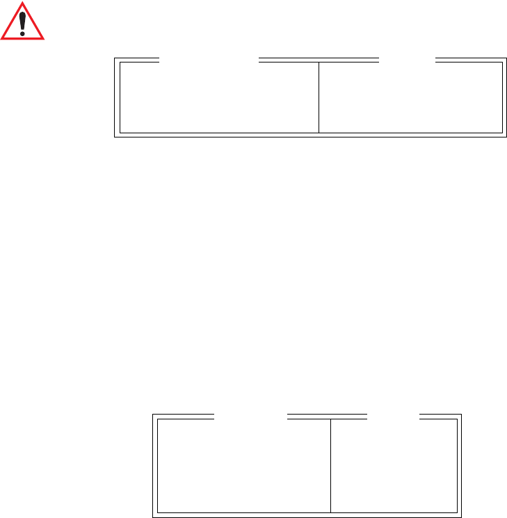
Teklogix 7035, 8255 & 8260 Terminals User Manual 117
Chapter 6: Setting Parameters
Host Conn
6.7.1.1 Host Conn
Important: This parameter is not available when the terminal is operating
with a narrow band radio.
Conn Type
This parameter allows the operator to choose one of the following types of
connections: TCP Direct if the terminal is communicating through a controller or
an SDK, or Telnet if the terminal is communicating directly to the host.
Host
This parameter is used to assign a host IP address using the format ###.###.###.###
Port
“Port” specifies the TCP Direct or Telnet port number. By default, the Telnet port is
assigned port number 23. The TCP Direct port is assigned the value 9999.
6.7.1.2 Screen
Pages
This parameter defines how many pages are accessible to application programs. The
ANSI control functions, Next Page (NP) and Previous page (PP), are used to select
another page. These pages are independent of each other, so that if lines of text
scroll off a page, the other pages are unaffected.
There is no error indication from the terminal if the memory required by the selected
number and size of pages exceeds the memory available in the terminal.
Conn Type Telnet TCP Direct/Telnet
Host see text
Port 23 0-9999
Range
Host Conn
Pages 4 0-16
Columns 80 80 or 132
Rows 24 4-60
Auto Wrap Y Y/N
Softkeys » see text
RangeScreen

Chapter 6: Setting Parameters
Screen
118 Teklogix 7035, 8255 & 8260 Terminals User Manual
Columns
This parameter defines the logical page width (in characters) used by the host
computer application. Emulator systems trim the host application screens to this
width. This page width cannot be smaller than the width of the terminal display.
Display panning is used if the page is wider than the display.
Note: The value in this parameter must be an even number.
Rows
This parameter defines the logical page length (in lines) used by the host computer
application. Emulator systems trim the host application screens to this length. This
page length cannot be smaller than the length of the terminal’s display. Display
panning is used if the page is longer than the display.
Note: The value in this parameter must be an even number.
Auto Wrap
If “Auto Wrap” is disabled (set to “N”), characters received when the cursor is at the
right edge of the screen replace the previously displayed characters. If “Auto Wrap”
is enabled (set to “Y”), the cursor wraps to the next line when the current line is
filled. The display scrolls up if the cursor is at the bottom margin.
Softkeys
Note: This menu uses string entry fields. For detailed information about com-
pleting this type of field, refer to “String Entry Parameters” on page 85.
Important: The sample menu above reflects the 7035 hand-held softkey
options. The Softkey menu in the 8255 and 8260 vehicle-mount
terminals provides six softkeys – <F1> to <F6>.
F1
F2
F3
F4
Softkeys

Teklogix 7035, 8255 & 8260 Terminals User Manual 119
Chapter 6: Setting Parameters
Char Set – North American And European
Softkeys are function keys that have been programmed to perform specific actions
in your application. These keys are identified through softkey labels, reverse video
labels that are displayed at the bottom of the terminal screen. These softkey labels
can be reconfigured using the menu attached to this parameter.
To edit a label:
•Position the cursor in the appropriate function key field within the
Softkey menu, and type a new name – preferably one that describes
the corresponding key’s function.
Note: Although you can enter up to 8 characters for each softkey label, the text
will be shortened to better fit in the available space on your display.
6.7.1.3 Char Set – North American And European
Important: When a character sent from the host cannot be displayed, a
right arrow character is used as a substitute.
Note: For details on Chinese and Korean character sets, refer to “Char Set –
Chinese And Korean” on page 121 for details.
This menu contains all the character sets available with your Teklogix terminal.
To choose a character set:
•Position the cursor on the character set you want to use, and press the
<RIGHT> or <LEFT> arrow key to set it to “Y”.
Once you’ve chosen and enabled (set to “Y”) a particular character set, you’ll need
to choose from the sub-menu attached to that character set.
•Press <F1> to display the character set options.
•To enable a character set option, press the <RIGHT> or <LEFT> arrow key
to set it to “Y”
ISO N »
IBM Y »
DEC N »
Char Set

Chapter 6: Setting Parameters
Char Set – North American And European
120 Teklogix 7035, 8255 & 8260 Terminals User Manual
ISO Options
IBM Options
ISO 8859-1 N
ISO 646 ASCII N
ISO
EBCDIC N »
Other Y »
IBM
5250 Multin’l N
IBM 037 N
IBM 256 N
IBM 237 N
IBM 871 N
IBM 875 N
Belgium N
Brazil N
British N
Danish/Norway N
Finnish/Swed. N
French N
French Cdn. N
Italian N
Portugal N
Spain N
Spanish N
EBCDIC
IBM PC 437 N
IBM PC 850 Y
Other

Teklogix 7035, 8255 & 8260 Terminals User Manual 121
Chapter 6: Setting Parameters
Char Set – Chinese And Korean
DEC Options
6.7.1.4 Char Set – Chinese And Korean
Important: If you are using a Chinese character set and a character sent
from the host cannot be displayed on the terminal screen, a
shaded box character is used as a substitute.
If you are using a Korean character set, a right arrow character is
used as a substitute.
Note: Refer to "Char Set – North American And European" beginning on
page 119 for details about selecting character sets.
Chinese Character Sets
VT220 British N
VT220 Danish N
VT220 Finnish N
VT220 French N
VT220 Fr. Cdn. N
VT220 German N
VT220 Italian N
VT330 Portugal N
VT330 Spanish N
VT220 Swedish N
Graphical N
Multinational N
DEC
ISO N »
IBM Y »
Misc N »
Char Set
ISO 646 ASCII
ISO
Chinese
IBM
Big 5
Misc

Chapter 6: Setting Parameters
Video
122 Teklogix 7035, 8255 & 8260 Terminals User Manual
Korean Character Sets
6.7.1.5 Video
Bold
The value assigned to this parameter specifies the actual video attributes to be
assigned to fields created with the “Bold” ANSI attribute – that is, “BLNK” (blink),
“ULIN” (underline), “REV” (reverse) or “NONE” (normal).
Blink
The value assigned to this parameter specifies the actual video attributes to be
assigned to fields created with the “Blink” ANSI attribute – that is, “BLNK” (blink),
“ULIN” (underline), “REV” (reverse) or “NONE” (normal).
Reverse
The value assigned to the “Reverse” parameter specifies the actual video attributes
to be assigned to fields created with the “Reverse” ANSI attribute – that is, “BLNK”
(blink), “ULIN” (underline), “REV” (reverse) or “NONE” (normal).
Underline
The value assigned to this parameter specifies the actual video attributes to be
assigned to fields created with the “Underline” ANSI attribute – that is, “BLNK”
(blink), “ULIN” (underline), “REV” (reverse) or “NONE” (normal).
ISO N »
IBM Y »
Misc N »
Char Set
ISO 646 ASCII
ISO
Korean
Korean Int
IBM Misc
Fujitsu Korean
KSC 5601
Bold NONE see text
Blink BLNK see text
Reverse REV see text
Underline ULIN see text
Video Range

Teklogix 7035, 8255 & 8260 Terminals User Manual 123
Chapter 6: Setting Parameters
Transmit
6.7.1.6 Transmit
Xmit Count
This parameter determines how many characters from the keyboard or scanner are
buffered by the terminal before being transmitted to the host. If 0 (zero) is selected,
the terminal transmits only according to the “Xmit Wait” parameter. If the ANSI
block mode features are used, this parameter should be set to 99.
Note: If the terminal is not in local edit mode, the <ENTER>, arrow, <CTRL>,
and function keys cause an immediate radio transmission regardless of
the “Xmit Count” parameter setting.
Xmit Wait
This parameter determines the length of time the terminal collects keystrokes before
transmitting them to the host. This value is specified in increments of one 10th of a
second (i.e., a value of 10 represents 1 second). If 0 (zero) is selected, the terminal
transmits only according to the “Xmit Count” parameter.
Note: If the terminal is not in local edit mode, the <ENTER>, arrow, <CTRL>,
and function keys cause an immediate radio transmission regardless of
the “Xmit Wait” parameter setting.
Dev Attr
This parameter specifies a device attribute string. This string can be up to 39
characters long. The terminal sends this string to the host when it receives a DA or
DECID control. Whether or not this parameter is set is dependent on the
requirements of the host computer.
Xmit Count 0-99
Xmit Wait 0-999
Dev Attr see text
Auto-Ans see text
Range
Transmit

Chapter 6: Setting Parameters
Keyboard
124 Teklogix 7035, 8255 & 8260 Terminals User Manual
Auto-Ans
This string can be up to 39 characters long and is sent by the terminal as a reply to
an “ENQ” character from the host. The “Auto-Answer” string is programmable in
the same manner as the keyboard macros. For example, this string can be used to
automatically send the user name and password when logging into the host. Refer to
"String Entry Parameters" on page 85 to 86 for detailed information.
6.7.1.7 Keyboard
Newline
When this parameter is disabled (set to “N”), a LF character received from the host
causes the cursor to move down one line in the same column. In addition, the
<ENTER> key transmits a CR. When enabled (set to “Y”), an LF character received
from the host causes the cursor to move to the first column of the next line. The
<ENTER> key transmits both a CR and an LF.
Echo Mode
The available echo modes are:
Smart: This mode reduces or eliminates the delay between typing a character on
the keyboard and displaying the character echoed by the host computer.
The terminal displays all printable characters on the screen before sending
them to the host. The terminal compares the characters echoed by the host
to the characters placed on the page and alters the display if the host
echoes are different.
The maximum number of characters waiting for echo is 25. Any addi-
tional characters are sent to the host but are not displayed. When the
terminal is in insert mode, smart echo is disabled.
Important: To suspend Smart echo mode if, for example, you are
entering a password, press <ALT> and type ‘.’ (period).
Characters will be replaced with a series of periods until
you press the <ENTER> key.
Newline N Y/N
Echo Mode Smart Smart, Local, Host
DEL Key BS BS, DEL
Keyboard Range

Teklogix 7035, 8255 & 8260 Terminals User Manual 125
Chapter 6: Setting Parameters
Keyboard
Local: In this mode, any character entered using the keyboard is displayed before
being sent to the host. Certain keys cause additional action at the terminal,
as shown in Table 6.2 on page 125.
Host: In this mode, the terminal sends all keyboard entries to the host and
displays only data received from the host.
Table 6.2 Function Of Special Keys In Local Echo Mode
DEL Key
This parameter determines which character is sent to the host – DEL (delete) or BS
(backspace). The host interprets how it will respond to the code. The selection made
at this parameter does not affect how the <DEL> key operates at the terminal.
Key Function
ENTER In Newline mode, this key moves the cursor to the first
column of the next line. In line feed mode, this key
moves the cursor to column one of the current line.
CTRL-G (Bell) The terminal beeps.
CTRL-H (Backspace) The cursor moves back one space.
CTRL-I (Tab) The cursor moves to the next horizontal tab stop.
CTRL-J (Line Feed)
CTRL-L (Form Feed) The cursor moves down one line in the same column.
CTRL-K (Vertical Tab) The cursor moves down to the next line with a vertical
tab set.
DEL This key deletes the character to the left of the cursor and
moves the cursor to the left by one position.

Chapter 6: Setting Parameters
Serial
126 Teklogix 7035, 8255 & 8260 Terminals User Manual
6.7.2 Serial
Async In
When this parameter is enabled (set to “Y”), the serial (async) port is ready to
receive input at all times.
Start/End
The start character is added to the beginning of the data received from the serial
(asynch) port. The end character is added to the end of the data received.
6.7.3 TESS Settings
Each session you create has its own “Settings” parameters. Additional ANSI
information is documented in Chapter 4: TESS Operations.
Terminal #
For every application session you create, the terminal number assigned in the
“Terminal #” parameter must be non-zero and unique. This parameter defines the
terminal number for the TESS session and uniquely identifies all transmissions to
and from the terminal.
Other applications running in the terminal, such as an ANSI session or another
TESS session must each have a different terminal number. In addition, each
Teklogix terminal using the radio link must have a unique terminal number.
Async In N Y/N
Start 0 0-255
End 0 0-255
Serial Range
Terminal # 1 see text
Host Conn » see text
Screen » see text
Characters » see text
Serial » see text
Tests » see text
Scanner » see text
Fields » see text
Features » see text
TESS Range

Teklogix 7035, 8255 & 8260 Terminals User Manual 127
Chapter 6: Setting Parameters
Host Conn
6.7.3.1 Host Conn
Important: This parameter is not available when the terminal is operating
with a narrow band radio.
Host
This parameter is used to assign a host IP address using the format ###.###.###.###
Port
“Port” specifies the TCP Direct port number. By default, the TCP Direct port is
assigned the value 9999.
6.7.3.2 Screen
Columns
This parameter defines the logical page width (in characters) used by the host
computer application. Emulator systems trim the host application screens to this
width. This page width cannot be smaller than the width of the terminal display.
Display panning is used if the page is wider than the display.
Note: The value in this parameter must be an even number.
Host see text
Port 23 0-9999
Range
Host Conn
Columns 80 20..132
Rows 24 4..100
Origin Scroll N Y/N
Field Scroll N Y/N
Pages Saved 16 1..16
App. Parameter -1 -1..79
Softkeys » see text
Range
Screen

Chapter 6: Setting Parameters
Screen
128 Teklogix 7035, 8255 & 8260 Terminals User Manual
Rows
This parameter defines the logical page length (in lines) used by the host computer
application. Emulator systems trim the host application screens to this length. This
page length cannot be smaller than the length of the terminal’s display. Display
panning is used if the page is longer than the display.
Note: The value in this parameter must be an even number.
Origin Scroll
When enabled (set to “Y”), the display window moves to the origin (upper-left
corner) after “LOCK-H” or “LOCK-B” messages.
Field Scroll
When enabled (set to “Y”), the display window moves to the left after entering a
new entry field.
Pages Saved
This parameter determines the number of pages that can be stored and recalled at
the terminal. Storing frequently used page data at the terminal reduces the need
for the host to retransmit complete page data over the radio link. Retransmitting data
can reduce the system response time. Increasing the number of saved pages
decreases the available memory for other functions.
App. Parameter
The “Application” parameter is sent to the host system as part of the response to
the TESS query command. Enter zero if this parameter is not used.

Teklogix 7035, 8255 & 8260 Terminals User Manual 129
Chapter 6: Setting Parameters
Characters
Softkeys
Note: This menu uses string entry fields. For detailed information about com-
pleting this type of field, refer to “String Entry Parameters” on page 85.
Important: The sample menu above reflects the 7035 hand-held softkey
options. The Softkey menu in the 8255 and 8260 vehicle-mount
terminals provides six softkeys – <F1> to <F6>.
Softkeys are function keys that have been programmed to perform specific actions
in your application. These keys are identified through softkey labels, reverse video
labels that are displayed at the bottom of the terminal screen. These softkey labels
can be reconfigured using the menu attached to this parameter.
To edit a label:
•Position the cursor in the appropriate function key field within the
Softkey menu, and type a new name – preferably one that describes
the corresponding key’s function.
Note: Although you can enter up to 8 characters for each softkey label, the text
will be shortened to better fit in the available space on your display.
6.7.3.3 Characters
F1
F2
F3
F4
Softkeys
Invis. 42 0-255
NULL 46 0-255
Char Set » see text
Err Func Key 0 0-255
V Match Char 0 0-255
H Match Char 0 0-255
Upper Case N Y/N
Range
Characters

Chapter 6: Setting Parameters
Char Set
130 Teklogix 7035, 8255 & 8260 Terminals User Manual
Invis
In TESS applications, some fields may be set as “invisible” or “non-display” fields.
This parameter determines the character that will mask the actual text typed. For
example, this feature is often used in password entry fields where the actual text
typed is replaced by asterisks.
* (asterisk) The ASCII equivalent for this character is 42.
NULL
This parameter specifies the character that identifies empty entry fields. (Note that
positions containing spaces are not considered empty.) Enter the ASCII equivalent
of this character. The most commonly used characters are:
_ (underline) The ASCII equivalent for this character is 95.
. (period) The ASCII equivalent for this character is 46.
6.7.3.4 Char Set
This menu contains all the character sets available within TESS:
•Position the cursor on the character set you want to use, and press the
<RIGHT> or <LEFT> arrow key to set it to “Y”.
•Once you’ve enabled (set to “Y”) a particular character set, you’ll need to
choose from the sub-menu attached to that character set.
•Press <F1> to display the character set options.
•To enable a character set option, press the <RIGHT> or <LEFT> arrow key
to set it to “Y”
ISO Options
ISO N »
IBM Y »
DEC N »
Char
ISO 8859-1 N
ISO 646 ASCII N
ISO

Teklogix 7035, 8255 & 8260 Terminals User Manual 131
Chapter 6: Setting Parameters
Char Set
IBM Options
DEC Options
EBCDIC N »
Other Y »
IBM
5250 Multin’l N
IBM 037 N
IBM 256 N
IBM 237 N
IBM 871 N
IBM 875 N
Belgium N
Brazil N
British N
Danish/Norway N
Finnish/Swed. N
French N
French Cdn. N
Italian N
Portugal N
Spain N
Spanish N
EBCDIC
IBM PC 437 N
IBM PC 850 Y
Other
VT220 British N
VT220 Danish N
VT220 Finnish N
VT220 French N
VT220 Fr. Cdn. N
VT220 German N
VT220 Italian N
VT330 Portugal N
VT330 Spanish N
VT220 Swedish N
Graphical N
Multinational N
DEC

Chapter 6: Setting Parameters
Char Set
132 Teklogix 7035, 8255 & 8260 Terminals User Manual
Err Func key
This parameter defines the function key that interrupts the normal sequence of
a terminal and causes an Error Reply message to be returned to the host. Enter
the number of the function key to be used as the Error function key (e.g., “1” for
function key 1).
This parameter should be set to zero unless there is a system requirement for Error
Reply messages. When the Error function key is entered, the terminal abandons all
queued procedures and TESS commands and returns an Error Reply message, with
a milestone, to the host. The host must respond with a milestone acknowledge
before the terminal accepts further TESS commands.
V Match Chr
This parameter enables visible field matching and defines the character that identifies
visible field match data from the host. Field matching allows the host to pre-load
data into an entry field that is compared with the user’s input. The terminal beeps if
the entered data does not match. Visible field matching means that the data to be
matched is displayed in the entry field.
Enter the decimal value for the ASCII character that will be used by the host to
identify visible match field data. Enter 0 (zero) to disable this feature.
Note: Another method of field matching is available directly through the
TESS data stream.
H Match Chr
This parameter enables hidden field matching and defines the character that identifies
hidden field match data from the host. Field matching allows the host to pre-load
data into an entry field that is compared with the user’s input. The terminal beeps
if the entered data does not match. Hidden field matching means that the data to be
matched is not displayed in the entry field.
Enter the decimal value for the ASCII character that will be used by the host to
identify hidden match field data. Enter 0 (zero) to disable this feature.
Note: Another method of field matching is available directly through the
TESS data stream.
Upper Case
When this parameter is set to “Y”, lowercase input is converted to uppercase.

Teklogix 7035, 8255 & 8260 Terminals User Manual 133
Chapter 6: Setting Parameters
Serial
6.7.3.5 Serial
Note: This menu uses “string entry” parameters. For detailed information
about entering data in this type of parameter, refer to “String Entry
Parameters” on page 85.
In
This parameter enables the serial port input fields. If enabled (set to “Y”), the TESS
application has exclusive use of the serial port. Data entered in these fields must
begin with a line feed and end with a carriage return.
Prefix
This parameter determines the start-of-message character on serial input. A value
of “0” (zero) indicates no prefix. Enter an ASCII numeric equivalent to represent the
start character.
Suffix
This parameter determines the end-of-message character on serial input. A
value of “0” (zero) indicates no suffix. Enter an ASCII numeric equivalent to
represent the end character.
Out
This parameter enables serial port output fields.
Prefix
This parameter determines the start-of-message character on serial output. A value
of “0” (zero) indicates no prefix. Enter an ASCII numeric equivalent to represent the
start character.
In N Y/N
Prefix 10 0-255
Suffix 13 0-255
Out Y Y/N
Prefix 10 0-255
Suffix 13 0-255
Serial Range

Chapter 6: Setting Parameters
Tests
134 Teklogix 7035, 8255 & 8260 Terminals User Manual
Suffix
This parameter determines the end-of-message character on serial output. A value of
“0” (zero) indicates no suffix. Enter an ASCII numeric equivalent to represent the
end character.
6.7.3.6 Tests
AutoRep Fn
This parameter determines which function key is sent to the host in auto reply mode.
The value represents the number of the function key – not the ASCII decimal
equivalent. After sending this key, the terminal locks and waits for the host to unlock
the terminal. To disable “AutoRep Fn”, set the “AutoRep T/O” parameter to zero.
AutoRep T/O
This parameter determines the time (in seconds) between the terminal unlocking
and the next transmission of the function key specified by the “AutoRep Fn”
parameter. A value of zero disables auto reply mode.
6.7.3.7 Scanner
ContNxtField
This parameter only applies to string entry data. When enabled (set to “Y”), this
parameter allows bar codes that are longer than the field length to continue in the
next field.
If “ContNxtField” is disabled (set to “N”) OFF data will flow into the next field.
AutoRep Fn 11-36
AutoRep T/O 0 0-255
Range
Tests
ContNxtField YY/N
Append Enter Y Y/N
Append F0 Y Y/N
Mixed AIAG N Y/N
Rjct if Alpha N Y/N
Beam Lockout N Y/N
Range
Scanner
Teklogix 7035, 8255 & 8260 Terminals User Manual 135
Chapter 6: Setting Parameters
Scanner
Append Enter
When enabled (set to “Y”), “Append Enter” causes an <ENTER> code to be
appended to the bar code. The <ENTER> code completes the entry of the bar code
and moves the cursor to the next field.
Append F0
When enabled (set to “Y”), this parameter causes an <F0> code to be appended to
the bar code. The <F0> code completes the entry of the bar code data in the field.
Mixed AIAG
When this parameter is enabled (set to “Y”), AIAG labels are always accepted and
processed – even if mixed with keyboard input. The AIAG label can replace the
partially entered keyboard data. If this parameter is disabled, AIAG labels are
rejected if field entry is in progress.
Rjct if Alpha
When the cursor is in a numeric field and “Rjct if Alpha” is enabled (set to “Y”),
bar codes containing alphabetic characters are rejected.
Beam Lockout
When enabled (set to “Y”), this parameter disallows scanner use when the current
session is in “LOCK-H” mode.

Chapter 6: Setting Parameters
Fields
136 Teklogix 7035, 8255 & 8260 Terminals User Manual
6.7.3.8 Fields
Field Order
This parameter determines the mode of cursor movement between fields. The next
field can be defined by location on the screen or by the assignment of field numbers.
When enabled (set to “Y”), the cursor moves according to field location. If disabled
(set to “N”), the cursor moves according to the numeric order of the fields.
Enter To F0
The <ENTER> key normally enters data into a field and moves the cursor to the
next field. However, some applications require that the <ENTER> key start a
transmission from the terminal. When enabled (set to “Y”), this parameter causes
the <ENTER> key to be interpreted as <F0> which starts a transmission.
Enter On Arr
When this parameter is enabled (set to “Y”), the arrow keys can be used to complete
data entry into a field.
Entry Mode
“Entry Mode” parameters allow you to select a data entry mode. The modes are:
insert, replace, field and fcursor. “TESS Edit Modes And Cursor Movement” on
page 65 describes these modes in detail.
Open Fky Only
When this parameter is enabled (set to “Y”), the screen is open for function keys
only, and the cursor is not positioned. When this parameter is disabled, the screen is
open for data entry, and the cursor is placed in the first field (if it exists).
Field Order YY/N
Enter To F0 Y Y/N
Enter On Arr Y Y/N
Entry Mode field see text
Open Fky Only N Y/N
Video » see text
All Fld Video Y Y/N
Ign Bcode_fld N Y/N
Enh Edit Mode N Y/N
Range
Fields

Teklogix 7035, 8255 & 8260 Terminals User Manual 137
Chapter 6: Setting Parameters
Fields
Video
Bold
The value assigned to this parameter specifies the actual video attributes to be
assigned to fields created with the “Bold” ANSI attribute – that is, “BLNK” (blink),
“ULIN” (underline), “REV” (reverse) or “NONE” (normal).
Blink
The value assigned to this parameter specifies the actual video attributes to be
assigned to fields created with the “Blink” ANSI attribute – that is, “BLNK” (blink),
“ULIN” (underline), “REV” (reverse) or “NONE” (normal).
Reverse
The value assigned to the “Reverse” parameter specifies the actual video attributes
to be assigned to fields created with the “Reverse” ANSI attribute – that is, “BLNK”
(blink), “ULIN” (underline), “REV” (reverse) or “NONE” (normal).
All Fld Video
Usually, the video attributes apply only to the text that is in an entry field. When this
parameter is enabled (set to “Y”), the entire field (including blanks) takes on the
video attributes. Some systems use this option to identify empty entry fields with
reverse video.
Ign Bcode_fld
When this parameter is enabled (set to “Y”), fields that were defined as “bar code
only” accept data from the keyboard as well as the bar code reader. In effect, they
behave as data entry fields.
Bold NONE see text
Blink BLNK see text
Reverse REV see text
Video Range

Chapter 6: Setting Parameters
Features
138 Teklogix 7035, 8255 & 8260 Terminals User Manual
Enh Edit Mode
This mode provides extended (enhanced) functionality to users of Teklogix’ IBM
5250 terminal emulation. When this parameter is enabled (set to “Y”), the arrow
keys move the cursor anywhere on the screen, unrestricted by fixed or entry fields.
Table 6.3 describes the cursor movement when an arrow key is pressed in
conjunction with the <SHIFT> key.
Table 6.3 Enhanced Edit Mode Cursor Key Operation
6.7.4 Features
Kbd Locked
This parameter allows you to lock (set to “Y”) or unlock (set to “N”) the keyboard
for all alphanumeric input in TESS. When the keyboard is locked, the Function
keys, arrow keys and the <ENTER> key are still functional. The terminal emits
an error beep if a character is rejected because the keyboard is locked. Changes to
this parameter take effect only after the terminal is reset.
Key Function Key Sequence Cursor Movement
Field Advance
or Tab <SHIFT> <RIGHT>
arrow key
Cursor moves to the first position in
the next input field. If already in the
last field, the cursor moves to the first
input field on the screen.
Field Backspace <SHIFT> <LEFT>
arrow key
Cursor moves to the beginning of
the current field. If already in the first
position, the cursor moves to beginning
of the previous field.
Field Exit <SHIFT> <DOWN>
arrow key
Current field is cleared, and the cursor
moves to the next input field.
Home <SHIFT> <UP>
arrow key
Cursor moves to the first input field on
the screen.
Kbd Locked N Y/N
Features Range

Teklogix 7035, 8255 & 8260 Terminals User Manual 139
Chapter 6: Setting Parameters
View Manager
6.8 View Manager
Anchor View
When enabled (set to “Y”), this parameter locks the display at a defined location on
the screen, preventing it from shifting when the cursor is moved. The “X-origin” and
“Y-origin” coordinates specify where the screen origin, the upper-left corner of the
screen, will be fixed.
X-origin And Y-origin
The “X-origin” parameter is used to specify the column to which the upper left
corner of the screen will be anchored. The “Y-origin” parameter is used to specify
the row coordinate to which the screen will be anchored.
Use increment
When “Use increment” is enabled (set to “Y”) and the cursor is moved off the
display, the screen contents shift by the values specified in the “X-increment” and
“Y-increment” parameters.
X-increment
This parameter determines the number of spaces the screen shifts once the cursor
moves out of view. The value assigned here doesn’t take effect until “Use
Increment” is set to “Y”.
Y-increment
This parameter determines the number of spaces the screen shifts once the cursor
moves out of view. The value assigned here doesn’t take effect until “Use
Increment” is set to “Y”.
Anchor View NY/N
X-origin 1 1-80
Y-origin 1 1-24
Use Increment N Y/N
X-increment 5 1-40
Y-increment 5 1-12
Display Shift Y Y/N
Custom Chars » see text
Range
View Manager

Chapter 6: Setting Parameters
View Manager
140 Teklogix 7035, 8255 & 8260 Terminals User Manual
Display Shift
If this parameter is enabled (set to “Y”), the display in application screens shifts so
that there are no blank columns on the left-most side of the display.
Custom Chars
This parameter is used to create a list of characters (to a maximum of 20 characters)
that are not normally available directly from the keyboard.
To create a character:
•Type the decimal equivalent of the character you want to create. You can
look up the decimal value in the code page you selected using the "Code
Page" parameter (see page 95).
Note: If the character you select does not exist in the host character set, it
cannot be sent to the host application.
Once you’ve created this list of characters, you can access the list from within a
TESS or ANSI session as follows:
•Press <ALT> a to display your list of custom characters.
•Use the <RIGHT> or <LEFT> arrow key to highlight the character you
require, and press <ENTER> to select it.
Char nn 0-255
•
•
•
Char nn 0-255
Range
Custom Chars

Teklogix 7035, 8255 & 8260 Terminals User Manual 141
Chapter 6: Setting Parameters
Ports– Serial 1 And Console 2
6.9 Ports– Serial 1 And Console 2
6.9.1 Serial 1 And Console 2 Peripheral Options
The “Serial 1” (COM1) and “Console 2” (COM2) options allow you to enable,
disable and specify the accessories attached to these ports. For the “Serial 1” port,
the possible values are: Disable Enable Print Scanner and Output. For
the “Console 2” port, the possible values for this parameter are: Disable Enable
Print Scanner and Scan-See and Nomad.
To scroll through the options for each port:
•Press the <RIGHT> or <LEFT> arrow key.
Important: If you choose Disable, the corresponding port parameters will not
take effect.
These ports operate differently depending on the accessories selected.
•“Print” – all TESS print operations are directed to the port. All ANSI media
copy operations to the “primary port” are directed to this port.
•“Scanner” – TESS and ANSI accept scanner input from the port.
•“Scan-See” – TESS and ANSI accepts input from the Scan-See through the
Console 2 port. (This option is not available for the Serial 1 port.)
•“Nomad” – TESS and ANSI accepts input from the Nomad scanner through
the Console 2 port. (This option is not available for the Serial 1 port.)
•“Output” – the TESS pass-through operations and serial output fields
are directed to the Serial 1 port. (This option is not available for the
Console 2 port.)
Serial 1 Print
Parameters »
Console 2 Disable
Parameters »
Ports

Chapter 6: Setting Parameters
Serial 1 And Console 2 Parameter Settings
142 Teklogix 7035, 8255 & 8260 Terminals User Manual
6.9.2 Serial 1 And Console 2 Parameter Settings
Since the parameters for the “Serial 1” and “Console 2” ports are identical in most
cases, they are discussed in one section. Any differences are clearly indicated.
Important: The most significant difference between the “Serial 1” and “Con-
sole 2” port parameters is that the ScanSee menu is only available
in the Console 2 “Parameters” menu.
Speed
This parameter determines the bit rate of the port.
Data Bits
This parameter determines the number of bits for the data going through this port.
Parity
This parameter determines the type of parity checking used on the data going
through the port. The options are Odd, Even and None.
Stop Bits
This parameter specifies the number of stop bits – 1 or 2 – used for asynchronous
communication.
Speed 9600 1200 2400 4800 9600
Data Bits 8 7-8
Parity None None Odd Even
Stop Bits 1 1-2
Flow Control None None CTS/RTS XON/XOFF
Buffer 512 32-2048
Retries 3 1-100
Input Tmo 2 0-100
Test Y Y/N
ScanSee » see text
Console 2 Range

Teklogix 7035, 8255 & 8260 Terminals User Manual 143
Chapter 6: Setting Parameters
Serial 1 And Console 2 Parameter Settings
Flow Control
Important: Flow Control is not available for Console 2.
This parameter selects the type of flow control used in your terminal. The 7035 can
perform XON/XOFF and/or CTS/RTS handshaking. Note that RTS/CTS hardware
flow control generally results in faster data throughput.
The function of each mode is as follows:
Enable: Used to input and output data.
Supports XON/XOFF and/or CTS/RTS or no handshaking
Print: Used to output data only. All input characters except XON and
XOFF are ignored.
Supports XON/XOFF and/or CTS/RTS or no handshaking.
Output: Used to output data only. All input characters are ignored.
Supports CTS/RTS or no handshaking
Note: To enable the input and/or output, ‘serial in’ and/or ‘serial out’ must be
enabled in the TESS menu.
Buffer
The value assigned to this parameter determines the size of the serial buffer used by
the application for both input and output. The buffer controls how much data the
application can send to or receive from a serial device.
Retries
Note: “Retries” is not available if “Nomad” is chosen as the peripheral device.
This parameter determines the number of times the terminal attempts to transmit a
byte from the serial port. If the count specified in this parameter is exceeded, the
transmission fails.
Input Tmo
This parameter sets the time in tenths of a second that the terminal waits before
passing received data to the TESS or ANSI tasks.

Chapter 6: Setting Parameters
Setting The Terminal Console Port For Nomad
144 Teklogix 7035, 8255 & 8260 Terminals User Manual
Test
When this parameter is enabled (set to “Y”), data is output through the serial port to
make certain that it is operating appropriately.
6.9.3 Setting The Terminal Console Port For Nomad
To interface the terminal to the Nomad scanner, “Console 2” must be configured for
Nomad. For detailed information about configuring the Nomad scanner, refer to the
“LS3070™ Wireless Scanner User Manual” – P.N. 80416.A
6.9.4 Setting The Terminal Console Port For Scan-See
Warning: ALWAYS DISCONNECT THE SCAN-SEE FROM THE
TERMINAL BEFORE A TERMINAL RESET! Resetting
the terminal with the Scan-See connected to it may cause it
to “hang” and boot up improperly.
In order for the terminal to interface to the Scan-See, the console port should be
set as follows:
Speed = 9600 baud
# of bits = 7
Parity = none
2stop bits = Y
Test = N
Note: In order for the terminal to interface to Scan-See units with older
firmware (serial numbers lower than 1594120224), set “Parity=space”;
all other parameters are identical to the newer firmware.
6.9.4.1 Scan-See Parameters
Note: Scan-Sees equipped with an LED screen have 10 column displays. The
newer Scan-Sees with LCDs have 20 column displays.
Teklogix 7035, 8255 & 8260 Terminals User Manual 145
Chapter 6: Setting Parameters
Model 7000 Settings – Defaults & Allowable Ranges
6.9.4.2 Model 7000 Settings – Defaults & Allowable Ranges
6.9.4.3 Model 7000M Settings – Defaults & Allowable Ranges
6.9.4.4 Scan-See Display – Mapping The "Viewport"
The Scan-See display is mapped to a specific area on the terminal screen called
the “Scan-See viewport” and is continuously updated to reflect that portion
of the screen. The Scan-See viewport is defined as follows:
Anchor Line 1 0...1
Anchor Column 9 0...19
Follow Cursor Y Y/N
Line Offset 0 -25...25
Column Offset -1 -80...80
Wraparound N Y/N
Panning Y Y/N
Line Scrolling N Y/N
Brightness 3 0 to 5
Arrows Bright Bright Horz Vert
Version 0 or 10...3 (see pg 149 for details)
XON/XOFF Y Y/N
04 Scan-See 30106-001
Default Setting
Model 7000 Range
Anchor Line 1 0...1
Anchor Column 19 0...19
Follow Cursor Y Y/N
Line Offset 0 -25...25
Column Offset -1 -80...80
Wraparound N Y/N
Panning Y Y/N
Line Scrolling N Y/N
Brightness n/a 0 to 5
Arrows Vert Bright Horz Vert
Version 2 or 30...3 (see pg 149 for details)
XON/XOFF Y Y/N
04 Scan-See
30107-001
Default Setting
Model 7000M Range

Chapter 6: Setting Parameters
Scan-See Display – Mapping The "Viewport"
146 Teklogix 7035, 8255 & 8260 Terminals User Manual
Anchor Line/Anchor Column
A location on the Scan-See display – the anchor – is chosen as a reference point.
Important: The range for this parameter varies depending on the type of
Scan-See you are using.
If you are using a Scan-See with a 10 column LED , the range for this parameter is 0
to 9. If you are using a Scan-See equipped with a 20 column LCD, the range for this
parameter is 0 to 19.
Line Offset/Column Offset
A predefined displacement – the offset – is added to the location of the terminal
cursor to give us a point – the pivot. This pivot is mapped to the anchor , and
whatever is displayed in its vicinity is also displayed on the Scan-See. For example:
•The anchor is chosen as (9,0) where “9” is the column and “0” is the line
(on the Scan-See display).
•The offset is chosen as (4,2).
•The cursor on the terminal is currently located at (7,5).
•The pivot would thus be located at (7+4, 5+2) or (11,7).
•The area displayed on the Scan-See will be:
(11–9,7–0) to (11–9+9,7–0+1) or (2,7) to (11,8).1
1These computations assume “Wraparound” (see page 148) is disabled, and
“Follow Cursor” is enabled.

Teklogix 7035, 8255 & 8260 Terminals User Manual 147
Chapter 6: Setting Parameters
Scan-See Display – Mapping The "Viewport"
Figure 6.1 Scan-See Viewport
Note: To enter negative values, press the “-” (minus) key, and then the number
you want to use.
The <LEFT> arrow key can also be used to decrement the value in
the parameter. Each time the <LEFT> arrow is pressed, the number is
decremented by one. For example, to enter a value of “–5”, start from
zero, and press the <LEFT> arrow five times.
(9,0)
anchor
Scan-See Display Terminal Display
superimposing
the anchor on the pivot
anchor
pivot
(11,8)
(11,7)
Scan-See Viewport
(2,7)
(11,7)
offset
+4
+2
(4,2)
offset
+4
+2
terminal
cursor
pivot = +
offset
(7,5)
terminal cursor
(0,0)
0123456789101112131415161718192021 . . .
(0,0)
0
1
2
3
4
5
6
7
8
9
10
11
. . .
0123456789101112131415161718192021 . . .
0
1
2
3
4
5
6
7
8
9
10
11
. . .
0123456789
0
1
(0,0)

Chapter 6: Setting Parameters
Scan-See Display – Mapping The "Viewport"
148 Teklogix 7035, 8255 & 8260 Terminals User Manual
Follow Cursor
When the “Follow Cursor” parameter is disabled (set to “N”), it is always assumed
that the cursor is located at the origin.
Using the previous example:
•the area displayed will be (4–9,2–0) to (4–9+9, 2–0+1), or, after clipping
values that are negative or higher than 80: (0,2) to (4,3).
Wraparound
When “Wraparound” is enabled (set to “Y”), the Scan-See display is treated as a
1 line by 20 column display rather than a 2 line by 10 column display. Keep in mind
that new Scan-Sees equipped with LCDs have 20 column displays.
Panning
If “Panning” is disabled (set to “N”), when the cursor moves one position to the
right and the pivot is still inside the Scan-See display, the Scan-See viewport
does not move. The Scan-See display is updated to reflect the changes within that
viewport. If the pivot goes outside the viewport, or if the terminal display changes
without the cursor being moved, the viewport is re-synchronized to coincide
the pivot with the anchor.
Line Scrolling
When “Line Scrolling” is enabled (set to “Y”), the Scan-See display is treated as
two separate 1 line by 10 column displays. The top line always displays the
previous value of the bottom line, so in an application where the cursor skips
from one entry field to another, the field that was just entered is shown on the top
line, and the field to be entered is shown at the bottom.
Note: When this feature is enabled (set to “Y”), the “Panning” option should be
disabled to prevent updates to both lines after every keystroke
Brightness
The “Brightness” parameter controls the backlight brightness of the display. It only
has an effect on Model 7000 Scan-Sees – scanners equipped with LED (light
emitting diode) displays.

Teklogix 7035, 8255 & 8260 Terminals User Manual 149
Chapter 6: Setting Parameters
Scan-See Display – Mapping The "Viewport"
Arrows
The “Arrows” parameter assigns one of three possible functions to the two arrow
keys on the Scan-See keyboard:
Table 6.4 Functions Of The Arrows Parameter
Note: For “Horiz” and “Vert,” changing the offset takes effect only after
the terminal display has been updated.
Version
Scan-See units with serial numbers that read 1594120224 or higher contain
firmware that implements a different communication protocol with the terminal
than older units. The “Version” numbers represent the following unit versions:
Table 6.5 Scan-See Versions
Note: To interface the terminal to the Scan-See units with older firmware
(serial number lower than 1594120224), set “Parity = space”;
all other parameters are identical to the newer firmware.
Refer to the Scan-See User Manual (P.N. 80408.C) for more information about
installing and using the Scan-See.
Value Function
“Bright”Arrow keys control Scan-See display brightness
“Horiz”Arrow keys control “Column Offset”
“Vert”Arrow keys control “Line Offset”
Value Scan-See Version
0First LED version – up to serial number 1594080275. These are
encased in grey plastic.
1Corresponds to Model 7000 LED units – versions after the serial
number above. These are also encased in grey plastic.
2Corresponds to the Metrologic 7000M LCD units. These are encased
in grey plastic.
3Corresponds to the current 7000M LCD units all of which are
encased in black plastic.

Chapter 6: Setting Parameters
Global Macros
150 Teklogix 7035, 8255 & 8260 Terminals User Manual
XON/XOFF
Important: IF YOU ARE USING TRANSCEIVERS WITH YOUR
SCAN-SEE, this parameter must be set to “Y”.
When set to “Y”, the XON and XOFF characters are not passed to the TESS or
ANSI tasks. A received XOFF character stops the serial port from transmitting. A
received XON character starts the serial port transmissions again.
6.10 Global Macros
A macro has 19 programmable characters (or “positions”). The macro keys can be
programmed to replace frequently used keystrokes, along with the function of
executable keys like <ENTER>, <DEL>, function keys and arrow keys. They may
also be used to provide characters not normally accessed from the keyboard.
The methods used to create macros are described in this section.
6.10.1 Displaying The Global Macros Menu
Macros are programmed from within the “Global Macros” menu. If the Tekterm
application is currently active:
•8255/8260: – Press <ALT> and type x to exit the Tekterm application.
•7035: Press <ORANGE> <ALT> before typing x.
The “Display Menu” appears on the terminal screen.
To display the “Parameters” menu:
•8255/8260: –Type the letter a.
•7035: Press <ORANGE> before typing a.
A Parameters
B Emulations
C DOS Prompt
01 Display Menu

Teklogix 7035, 8255 & 8260 Terminals User Manual 151
Chapter 6: Setting Parameters
Displaying The Global Macros Table
•Type your password in the Password window, and press <ENTER>.
6.10.2 Displaying The Global Macros Table
To display the “Global Macros” table:
•From the “Parameters” menu, position the cursor on the “Global Macros”
option, and press <F1> to display the macro table.
Note: This is a sample 7035 macro table. Vehicle-mount terminals displays 12
macro fields rather than 4.
•Position the cursor in the macro field corresponding to the macro key to
which you want to assign macros – #1 corresponds to macro key <M1>,
#2 corresponds to macro key <M2>, and so on.
Once the cursor is in a macro field, you have a number of options when creating a
macro. You can type text and numbers, choose from a set of ASCII characters and
program the function of special keys into a macro.
System »
Scanner »
Applications »
View Manager »
Ports »
Global Macros »
Network »
Radio »
Sound »
Parameters
#1
#2
#3
#4
Global Macros

Chapter 6: Setting Parameters
Choosing An ASCII Character
152 Teklogix 7035, 8255 & 8260 Terminals User Manual
In macros, the <UP> arrow, <DOWN> arrow, <ENTER> and <DEL> keys have the
following functions:
•Pressing the <UP> and <DOWN> arrow keys move the cursor between
entry fields.
•Pressing the <ENTER> key once moves the cursor to the first position in
the entry field; pressing <ENTER> a second time completes the entry field,
exits the sub-menu and returns the cursor to the “parent” or previous menu.
•The <DEL> key deletes the character to the left of the cursor.
•The <CLR> key – <BLUE> <DEL> – clears the entire field. If the last
character in a field is deleted, the previous contents, if any, reappear.
6.10.3 Choosing An ASCII Character
Important: Make sure the <CTRL> and <SHIFT> keys are turned off!
By pressing either the <RIGHT> or <LEFT> arrow key, you can cycle through a set
of printable characters not available on the keyboard. The sample below is a set of
ASCII characters not accessible from the keyboard.
7035: / < > % ^ & ` ~ | [ ] { } " ' ? = + ;
8255/8260: ^ & ‘ ~ | [ ] { } ’ "
•Press the <RIGHT> arrow to display the next character in this sequence,
and the <LEFT> arrow to display the previous one.
6.10.4 Adding Additional ASCII Characters
When you’ve chosen an ASCII character and want to add another one in the same
field, the cursor must be moved to the right of the existing character. Normally,
pressing the <RIGHT> arrow key moves the cursor to the right, but in a string entry
field, pressing the <RIGHT> arrow key cycles through the available ASCII
characters instead. If you’ve already chosen an ASCII character and want to
add another one in the field, you need to take a few extra steps to move the cursor
to the right.
To add another ASCII character in the string entry field, next to the one you’ve
already chosen:
•Type a numeric character – for example, type the number 7.
•Next, press the <DEL> key
The cursor is now positioned to the right of the previously selected ASCII character.
•Press the <RIGHT> or <LEFT> arrow key to scroll through the ASCII
characters, and select another character.

Teklogix 7035, 8255 & 8260 Terminals User Manual 153
Chapter 6: Setting Parameters
Programming Special Keys Into Macros
6.10.5 Programming Special Keys Into Macros
Macros can contain the function of a subset of terminal keys. The keys that can be
programmed into macros include: <ENTER>, <DEL> and <CLR> (<BLUE>-
<DEL>), function keys and arrow keys. To program the function of a key:
•With the cursor in the “Global Macros” table, use the arrow keys to position
the cursor in the macro field corresponding to the macro key you want to
program – the field labelled #1 represents <M1>, and so on.
•Press <CTRL> and then, type the letter l (el) (l represents “literal”).
•Press the key you wish to add to the macro.
For example: To execute the function of the <ENTER> key in a macro,
type <CTRL> l <ENTER>.
6.11 Network
Note: This menu is not displayed when a Mobitex TRX7460 radio is installed in
the terminal.
Local IP
This parameter is used to assign a unique terminal IP address so that the terminal
can be identified on the network. The format is ###.###.###.###
Net Mask
A subnet mask is assigned at this parameter. The 7035 uses the subnet mask, it’s
own IP address and the destination IP address to determine if a packet should be sent
on the local network or a remote subnet. If the destination is found to reside on the
local network, the packet is sent directly to its destination. If the destination resides
on a remote subnet, the packet is routed to the appropriate gateway. The accepted
values for “Net Mask” range from 0.0.0.0 to 255.255.255.255.
Local IP see text
Net Mask see text
Default Gateway see text
Employ bootp N Y/N
Network Range

Chapter 6: Setting Parameters
Radio
154 Teklogix 7035, 8255 & 8260 Terminals User Manual
Default Gateway
The “Default Gateway” IP address assigned at this parameter creates an identifiable
communication link between the terminal and a remote sub-network – that is, a
network other than the one in which the terminal is currently operating. The
acceptable values for this parameter range from 0.0.0.0 to 255.255.255.255.
Note: Setting the “Default Gateway” to 0.0.0.0 disables this feature.
A communication link will not exist between sub-networks.
Employ Bootp
When this parameter is set to “Y”, a request for an IP address is automatically
directed to the “BOOTP Server”. If after 5 attempts, an IP address is not transmitted,
the terminal uses the IP address assigned in the “Local IP” parameter.
6.12 Radio
Refer to Appendix D: Radio Parameters for a detailed description of the parameters
used to adjust radio communications.
6.13 Sound
Beep Tone And Beep Time
These parameters regulate the frequency and duration of beeps emitted in a TESS or
ANSI session when one of the following is received at the terminal: an advisory, a
hey you or a bell character. Tone is measured in hertz and time in milliseconds.
Beep tone 2300 500-5000
Beep time 600 0-2000
Error tone 800 500-5000
Error time 600 0-2000
Scan tone 1 1250 500-5000
Scan time 1 150 0-2000
Scan tone 2 2300 500-5000
Scan time 2 150 0-2000
Scan tone 3 3750 500-5000
Scan time 3 150 0-2000
Sound Range
Teklogix 7035, 8255 & 8260 Terminals User Manual 155
Chapter 6: Setting Parameters
Sound
Error Tone And Error Time
These parameters determine the frequency and duration of each error tone. Tone is
measured in hertz and time in milliseconds.
Scan Tone 1 And Scan Time 1
“Scan tone 1” and “Scan time 1” determine the frequency and duration of the first
beep of a multiple beep. Tone is measured in hertz and time in milliseconds.
Scan Tone 2 And Scan Time 2
“Scan tone 2” and “Scan time 2” determine the frequency and duration of the
second beep of a multiple beep. Tone is measured in hertz and time in milliseconds.
Scan Tone 3 And Scan Time 3
“Scan tone 3” and “Scan time 3” determine the frequency and duration of the third
beep of a multiple beep. Tone is measured in hertz and time in milliseconds.

Teklogix 7035, 8255 & 8260 Terminals User Manual 157
TERMINAL ACCESSORIES 7
7
7.1 External Bar Code Readers..........................159
7.1.1 Entering Data With A Bar Code Reader ................159
7.2 The 7035 Battery ...............................160
7.2.1 Lithium-Ion Battery Safety Precautions ................161
7.2.2 Lithium-Ion Battery Pack Specifications ...............162
7.3 The 7942 In-Unit Charger ..........................163
7.3.1 Mounting Bracket ...........................164
7.3.2 Connecting The Power Source.....................164
7.3.3 In-Unit Charger LED Indicators ....................164
7.3.4 Inserting The 7035 With Battery In The Charger ...........165
7.3.5 Charging The Battery .........................165
7.3.6 Battery Charge Fault Conditions....................165
7.3.7 Charger Fault Conditions .......................166
7.3.8 Removing The Terminal From The In-Unit Charger .........166
7.3.9 7942 Charger Specifications ......................166
7.4 The 7967 Gang Charger ...........................167
7.4.1 Connecting The Power Source.....................167
7.4.2 Inserting And Charging The Battery..................167
7.4.3 Fault Conditions ............................168
7.4.3.1 Fault LED Turns On During A Charge .............168
7.4.3.2 Fault LED Turns On At Insertion ................168
7.4.4 7967 Charger Specifications ......................169
7.5 Important Charger Safety Instructions ....................169
7.6 Antenna Types ................................170
7.7 The 7035 Picker Cradle............................171
7.7.1 Mounting Hardware ..........................171
7.7.2 Installation ...............................171
Chapter 7: Terminal Accessories
158 Teklogix 7035, 8255 & 8260 Terminals User Manual
7.7.3 Disassembling The Cradle Before Mounting..............172
7.7.4 Mounting The Cradle..........................173
7.7.5 Installing The Cables ..........................173
7.7.6 Connecting A Cable ..........................173
7.7.7 Connecting The Power Source .....................174
7.7.8 Attaching A Port Replicator ......................174
7.7.9 Picker Cradle Maintenance .......................174
7.7.10 Inserting And Removing The 7035 Terminal .............175
7.7.11 Picker Cradle LED Indicator .....................176
7.7.12 Specifications .............................177
7.7.12.1 Physical ............................177
7.7.12.2 Environmental ........................177
7.7.12.3 Battery Pack .........................177
7.7.12.4 Agency Approvals ......................178
7.8 Accessories Part Number List.........................179

Teklogix 7035, 8255 & 8260 Terminals User Manual 159
Chapter 7: Terminal Accessories
External Bar Code Readers
7.1 External Bar Code Readers
Warning: ALWAYS TURN THE TERMINAL OFF before connecting or
disconnecting any bar code reader.
To connect a bar code reader (either a scanner or a contact wand) to the terminal,
attach the device to the 28-pin peripheral port at the bottom of the unit.
Before using the bar code reader, you may need to change some parameters.
For details, review “Barcode” on page 105.
7.1.1 Entering Data With A Bar Code Reader
The terminal supports two types of bar code readers: contact wands or scanners.
To use a scanner, follow the manufacturer’s instructions. Use the wand as follows:
•Hold the wand at less than 30° from the vertical.
•If there is a switch on the wand, turn it on before starting the scan.
•Keep the tip in contact with the entire label.
•Move the wand across the label at a steady rate.
•Begin the scan on an area of the label with a light background, and move
the wand as if drawing a straight line across the label.
Figure 7.1 Using A Wand Bar Code Reader
If the label is scanned successfully, the scanned data appears on the display.
The terminal will also beep if configured appropriately.
Occasionally, the bar code labels are poorly printed or damaged and cannot be read
with the wand. In this case, use the keyboard to enter data from the label.
0 00 75328 43815 0
Centre Line
of Wand
Vertical
Centre
Bar Code
Surface
30
Centre Line
of Wand
Centre Line
of Wand
30

Chapter 7: Terminal Accessories
The 7035 Battery
160 Teklogix 7035, 8255 & 8260 Terminals User Manual
7.2 The 7035 Battery
Warning: When a battery is removed from the terminal, a backup of the
system, application and any work in progress is maintained for
up to 10 minutes. A fresh battery must be installed within this
10 minute time frame. THIS BACKUP WILL NOT FUNCTION
UNLESS THE TERMINAL IS TURNED OFF BEFORE THE
BATTERY IS REMOVED. Removing the battery while the unit is
operating will result in a full reboot.
Even after the system backup has expired, the date and time are
maintained for at least 72 hours without a battery.
7035 Lithium-Ion batteries operate for a minimum of eight hours1 after a charge.
These batteries do not require conditioning. Each battery pack tracks its own
capacity using an onscreen horizontal bar graph, referred to as the “battery gauge”.
The battery gauge displays the percentage of remaining battery power capacity –
0 to 100%, resolution 10% of nominal capacity. The operator is notified when the
battery capacity is low.
Typical battery life is 750 cycles or 3 years average use. A fast charge is completed
in 2.5 hours. The 7035 terminal will notify the user when the battery performance
has degraded to the point that it should be discarded.
1Times are approximate and may vary depending on operating conditions.

Teklogix 7035, 8255 & 8260 Terminals User Manual 161
Chapter 7: Terminal Accessories
Lithium-Ion Battery Safety Precautions
7.2.1 Lithium-Ion Battery Safety Precautions
Important: It is critical that this safety information be reviewed and that all
warnings be strictly followed.
Warning: BATTERIES ARE CONSIDERED HAZARDOUS WASTE and
must be returned to Teklogix for proper disposal. All used batteries
must be forwarded to one of the following Teklogix offices:
Teklogix Inc. Teklogix Corp.
2100 Meadowvale Blvd. 1810 Airport Exchange Blvd.
Mississauga, Ontario Suite 500
Canada Erlanger, Kentucky
L5N 7J9 USA 41018
Teklogix S.A.
Parc Club Du Golf-Bat 1.
13856 Aix-En-Provence
Cedex 3; France
Warning: TO PREVENT the battery from leaking acid, generating heat or
exploding, adhere to precautions listed below.
•The battery incorporates built-in safety devices. To ensure
their proper function, do not disassemble or alter any parts
of the battery.
•Do not short-circuit the battery by directly connecting any of the exposed
terminals with metal objects such as wire. Do not transport or store the
battery together with metal objects such as necklaces, hair pins, etc.
•Do not dispose of batteries in fire.
•Do not use or leave the battery near a heat source such as a fire
or heater.
•Do not immerse the battery in water.
•When charging, use the battery charger specifically designed for
the battery.
•Do not pierce, strike, throw or step on the battery.
•Do not directly solder the battery.
•Do not connect the battery to an electrical outlet, vehicle
cigarette lighter, etc.
•Do not put battery into a microwave oven or pressurized container.
•Do not use the battery in combination with primary batteries (such as
dry-cell batteries) or batteries of different capacities or brands.
Chapter 7: Terminal Accessories
Lithium-Ion Battery Pack Specifications
162 Teklogix 7035, 8255 & 8260 Terminals User Manual
•Immediately remove the battery from the device or battery charger
and stop use if the battery gives off an odor, generates heat, becomes
discoloured or deformed, or in any way appears abnormal during use.
•Do not continue charging the battery if it does not recharge within the
specified charge time.
•The battery may burst or ignite if the battery leaks. Always ensure that it
is away from any exposed flames.
•If leaking electrolyte sprays into your eyes, rinse them with clean
running water, and immediately seek medical attention.
•Do not store the battery in extremely high temperatures (e.g., a vehicle,
strong direct sunlight, etc.). This may cause the battery to overheat
or ignite, and it may also reduce the performance and service life of
the battery.
•Do not use in areas where static electricity is greater than what the
manufacturer guarantees.
•Keep batteries out of reach of children.
7.2.2 Lithium-Ion Battery Pack Specifications
Battery Pack
Technology Lithium-Ion (Li-Ion)
Supported packs P.N. 20605
P.N. 20605-001
P.N. 20605-002
Battery pack P.N. 20605
Charge temperature 0˚ C to 45˚ C (32˚ F to 113˚ F).
Discharge temperature -20˚ C to 60˚ C (-4˚ F to 140˚ F).
Battery pack P.N. 20605-001
Charge temperature 10˚ C to 45˚ C (50˚ F to 113˚ F).
Discharge temperature -20˚ C to 60˚ C (-4˚ F to 140˚ F).
Battery pack P.N. 20605-002
Charge temperature 10˚ C to 45˚ C (50˚ F to 113 ˚ F).
Discharge temperature -20˚ C to 60˚ C (-4˚ F to 140˚ F).
Life span Pack performance does not degrade below 70%
of nominal under typical daily use over 2 years.
(Based on 3 charge/discharge cycles every 2 days
and 250 working days/year.)

Teklogix 7035, 8255 & 8260 Terminals User Manual 163
Chapter 7: Terminal Accessories
The 7942 In-Unit Charger
Charge Cycles Minimum of 750 charge cycles.
Charge Time Fast charge typically in 2.5 hours.
Performance Monitor Identifies the need for pack replacement.
Voltage 7.2 V nominal (6.0 V to 8.4 V maximum)
Capacity 1350 mAh at 7.2 V nominal
Weight 115 g nominal
Battery Life 8 hours minimum at 23˚ C (73.4˚ F) with back-
light on 5%, 5 scan transactions per minute,
TESS emulation, TRX7370 radio. Based on
typical 1 year cell degradation.
Supported Chargers Model #7967 – 6-gang custom charger
Model #7942 – In-unit charger
Memory No memory effect.
Battery Gauge Indicates remaining capacity, 0 to 100%,
resolution 10%. Nominal capacity of battery
pack is displayed as a reference.
Graceful Power Fail Operator is notified when battery capacity is low.
7.3 The 7942 In-Unit Charger
Important: The 7035 cannot be switched on while it is inserted in the 7942 in-
unit charger. In fact, if the terminal is “on” when it is inserted in
the charger, it is automatically switched off.
The 7942 In-Unit Charger is a single site, fast charger. This unit can charge Lithium-
Ion or Nickel-Metal Hydride batteries.
Note: To ensure that air flow through the base of the charger is unimpeded,
the charger should be placed on a hard, flat surface, free of possible
obstructions.

Chapter 7: Terminal Accessories
Mounting Bracket
164 Teklogix 7035, 8255 & 8260 Terminals User Manual
7.3.1 Mounting Bracket
The optional mounting bracket allows the 7942 charger to be permanently secured
to a table or bench, permitting “one-handed” removal of the 7035 terminal from the
unit. Charging temperature is restricted to from 10° to 30° C (50° to 86° F).
To attach the mounting bracket:
•Remove the two rubber feet closest to the front of the charger. Retain
the screws.
•Secure the mounting bracket to the charger using the screws removed
from the rubber feet.
•Use two #8 wood screws to secure the bracket to the appropriate surface
7.3.2 Connecting The Power Source
•Plug the female end of the AC line cord into the IEC connector at the back
of the charger.
•Plug the other end of the AC line cord into an appropriate power source.
When the charger is plugged in, all the LEDs turn on for a few seconds during a
self-test. The “Power” LED then remains on, indicating a power connection.
7.3.3 In-Unit Charger LED Indicators
Table 7.1 Charger LEDs
LED Indicator Definition
Power – Green •Always on when the charger is plugged in.
Charge – Yellow •On during charge process.
•Off once battery is fully charged.
Fault – Red
•Blinking if a battery charge fails.
•On solid when battery is rejected.
(See “Battery Charge Fault Conditions” on page 165 and
“Charger Fault Conditions” on page 166 for details.)
Ready – Green •On when charge is completed successfully.

Teklogix 7035, 8255 & 8260 Terminals User Manual 165
Chapter 7: Terminal Accessories
Inserting The 7035 With Battery In The Charger
7.3.4 Inserting The 7035 With Battery In The Charger
The 7942 Charger has a “Power” LED along with three additional LEDs – Ready,
Charge and Fault. Ensure that the green “Power” LED at the front of the charger is
“on”. The in-unit battery charge pocket is moulded, making it easy to slide the
terminal into the charger well.
•Grasp the terminal just below the display with the keyboard facing you, and
slide the lower portion of the terminal with battery into the charger.
•Apply steady, gentle downward pressure to properly mate the charger
connector with the battery in the terminal.
7.3.5 Charging The Battery
When the terminal with battery is inserted in the charger, all LEDs light up. After a
few seconds, the “Ready” and “Fault” LEDs turn off. The “Charge” LED remains
on, indicating the fast charge is in progress. The “Power” LED should always be on.
Note: If the 7035 is powered up when it is inserted in the charger, it will be
turned off automatically.
Battery Charged And Ready
Typically, a fast charge takes 2.5 to 3.5 hours. When the “Charge” LED turns off and
the green “Ready” LED turns on, the fast charge cycle is complete and the terminal
is ready for use.
7.3.6 Battery Charge Fault Conditions
The “Fault” LED remains on under one of the following circumstances:
•The charger cannot read valid data from the battery pack.
•The battery is not compatible with the 7942 charger.
•The battery pack is set to “inhibit charge”.
•The battery is defective (cell damage).
•The battery temperature is outside the acceptable charge range.
Chapter 7: Terminal Accessories
Charger Fault Conditions
166 Teklogix 7035, 8255 & 8260 Terminals User Manual
The “Fault” LED blinks when a charge process has failed. Some possible causes are
listed below:
•The battery temperature has gone outside of the acceptable charge range.
•The charger cannot communicate with the battery pack.
•The battery is defective.
•The battery did not complete the charge cycle within the maximum timeout
period.
When the terminal is removed from the charger, the “Fault” LED should turn off. If
this LED remains on after the terminal is removed, refer to “Charger Fault
Conditions” on page 166.
7.3.7 Charger Fault Conditions
An internal charger fault is indicated if:
•The “Fault” LED remains illuminated after the terminal is removed.
•All LEDs turn on and remain illuminated when the charger is powered up.
•All LEDs turn on during normal operation.
Power should be cycled to the charger to correct these problems. If any of these
symptoms occur persistently, the charger unit should be repaired by a qualified
service technician.
7.3.8 Removing The Terminal From The In-Unit Charger
To remove the terminal from the charger:
•Apply steady downward pressure to the front of the charger with one hand
while pulling up on the terminal. If necessary, you may need to use a gentle,
side-to-side rocking motion to slide the terminal out of the charger well.
7.3.9 7942 Charger Specifications
Charge Sites 1 dedicated for in-unit charging
Charge Time 2.5 to 3.5 hours
Compatibility Lithium-Ion (Li-Ion), Nickel-Metal Hydride (NiMH).
Connection Via contacts at base of battery pack (battery must be
installed in terminal).
Teklogix 7035, 8255 & 8260 Terminals User Manual 167
Chapter 7: Terminal Accessories
The 7967 Gang Charger
Charge Operation Charging occurs automatically upon insertion without
user intervention. Indicators display charge status.
Lifetime: Minimum 5000 pack insertions, typical 10,000
insertions.
Reliability Self-cleaning contacts.
Power Supply Autoranging (100-240 VAC ± 10%, 50/60 Hz
7.4 The 7967 Gang Charger
The 7967 Gang Charger can charge up to six Lithium-Ion batteries at one time.
7.4.1 Connecting The Power Source
The 7967 Gang Charger is powered using a universal AC input. It accepts voltages
ranging from 100-230 volts AC, 50/60 Hz. The AC receptacle, an IEC 320 type
connector, is located at the back of the charger.
•Plug the female end of the AC line cord into the IEC connector at the back
of the charger.
•Plug the other end of the AC line cord into an appropriate power source.
All front panel LEDs turn on for a few seconds during a self-test mode. The “Power
On” LED then remains on, indicating a power connection.
•Check to make sure that the fan is running.
7.4.2 Inserting And Charging The Battery
The 7967 Gang Charger has a “Power On” LED and each charge pocket has three
LEDs – Charge, Fault and Ready. Ensure that the green “Power On” LED at the
front left side of the charger is “on”. The battery charge pockets are moulded,
making it easy to snap the batteries into the pockets.
•With the four electrical contacts facing down and textured plastic battery
surface facing the front of the charger, insert the battery into a charger
pocket. It should click into place.
Charging will begin immediately.
Chapter 7: Terminal Accessories
Fault Conditions
168 Teklogix 7035, 8255 & 8260 Terminals User Manual
Battery Charged And Ready
When the “Charge” LED turns off and the green “Ready” LED turns on, the fast
charge cycle is complete, and the battery is ready for use.
Typically, a fast charge takes 2.5 hours. Note that for Lithium-Ion batteries, 70% of
the charge occurs within the first hour.
7.4.3 Fault Conditions
The red “Fault” LED turns on to indicate that the battery pack has been rejected
or the charge process has failed.
7.4.3.1 Fault LED Turns On During A Charge
•The battery temperature has changed such that it is outside of the
acceptable range and the fast charge is halted. Remove the battery and
permit it to warm or cool to room temperature before reinserting and
restarting the charge.
•The battery is defective – for example, the battery may have a weak cell, an
open cell or a short.
•The battery did not complete the charge cycle within the maximum
timeout period. Clean the battery contacts and try inserting the battery
for charging. Check the battery parameter performance using the utility
provided in the 7035. Try another recharge cycle.
7.4.3.2 Fault LED Turns On At Insertion
•The charger cannot read valid data from the battery. Clean the battery
contacts and try charging the battery again.
•In some cases, foreign matter may block the battery receptacle interface.
Check the charger receptacle for debris and clear if required.
•The hand-held terminal has set the pack to inhibit the charge. In this
case, the battery is no longer useful and the battery should be returned
to Teklogix Inc. for proper disposal. Return addresses are listed on
page 161.
•The battery is not compatible with this charger.
•The battery temperature is outside of the acceptable range and the fast
charge is inhibited. Remove the battery and permit it to warm or cool to
room temperature before reinserting and restarting the charge.

Teklogix 7035, 8255 & 8260 Terminals User Manual 169
Chapter 7: Terminal Accessories
7967 Charger Specifications
7.4.4 7967 Charger Specifications
Charge Sites 6
Compatibility Lithium-Ion batteries only.
Connection Via contacts at top of battery pack.
Charge Operation Charging occurs automatically upon insertion without
user intervention. Indicators display charge status.
Limitations Will not charge NiMH batteries. However, if a NiMH
battery is inserted in this charger, neither the battery nor
the charger will be damaged.
7.5 Important Charger Safety Instructions
•SAVE THESE INSTRUCTIONS – This manual contains important safety
and operating instructions for battery charger Model 7967 and 7942.
•Before using the battery charger, read all instructions and cautionary
markings on (1) battery charger, (2) battery, and (3) product using battery.
•Use of an attachment not recommended or sold by the battery charger
manufacturer may result in fire, electric shock, or personal injury.
•To reduce risk of damage to the electric plug and cord when unplugging the
charger, pull the plug rather than the cord.
•Make sure the cord is positioned so that it is not stepped on, tripped over,
or otherwise subjected to damage or stress.
•Do not operate the charger with a damaged cord or plug.
Replace immediately.
•Do not operate the charger if it has received a sharp blow, been dropped,
or otherwise damaged in any way; it should be inspected by qualified
service personnel.
•Do not disassemble the charger; it should be repaired by qualified service
personnel. Incorrect reassembly may result in electric shock or fire.
•To reduce risk of electric shock, unplug the charger from the outlet before
attempting any maintenance or cleaning.

Chapter 7: Terminal Accessories
Antenna Types
170 Teklogix 7035, 8255 & 8260 Terminals User Manual
•An extension cord should not be used unless absolutely necessary. Use of
an improper extension cord could result in fire or electric shock.
If an extension cord must be used, make sure:
•The plug pins on the extension cord are the same number, size,
and shape as those on the charger.
•The extension cord is properly wired and in good electrical
condition and that the wire size is larger than 16 AWG.
•Do not expose the charger to rain or snow.
•Do not place batteries in the charger if they are cold from extended
exposure to a freezer or outside temperatures below 10°C (50°F). Allow
them to warm up to room temperature for at least two hours.
•Do not use the charger if, after an overnight charge, any of the batteries feel
warmer than the charger housing. The charger should be inspected by
qualified service personnel.
•Do not use the charger if any of the batteries or the charger get more than
lukewarm. The equipment should be inspected by qualified personnel.
7.6 Antenna Types
Available external whip antennas include a 3 inch 2.4 GHz dipole whip and a
4 inch VHF whip.
Table 7.2 7035 Antennas
Antenna
Type Connector Type Antenna Whip Model
Description
Internal Plastic Cap N/A N/A
External Reverse gender
SMA 2.4 GHz Dipole
P.N. 20667
7035-SS
(Spread Spectrum)
External Standard SMA VHF Whip
P.N. 20668
7035-NB
(Narrowband)

Teklogix 7035, 8255 & 8260 Terminals User Manual 171
Chapter 7: Terminal Accessories
The 7035 Picker Cradle
7.7 The 7035 Picker Cradle
Picker cradles provide physical support for terminals, allowing “hands-free”
operation. Teklogix offers three types of picker cradles:
•Model number 7937A – an unpowered picker cradle.
•Model number 7937B – a powered picker cradle with 11-16VDC input.
•Model number 7937C – a powered picker cradle with 10-55 VDC input.
7.7.1 Mounting Hardware
The 7035 Picker Cradle can be mounted on its own or with one of the following:
•Heavy-duty pedestal mount (PN 30082)
•Pedestal mount with locking joint (PN 18447-001)
•Vertical mounting plate (PN 18440-001)
•Horizontal mount plate (PN 18448-001)
•Scanner mounting plate (PN 18449-001)
•Scanner holder (PN 92892)
•Port replicator (PN 21658)
7.7.2 Installation
Note: Where applicable, the unit should be mounted inside the roll cage.
Installation requirements vary depending on the type of application used – mobile
(e.g., a fork lift truck) or fixed (e.g., a work table). For a typical installation:
1. Choose a suitable mounting location.
2. If necessary, connect the pass-through cable to an accessory.
3. Connect the power source.

Chapter 7: Terminal Accessories
Disassembling The Cradle Before Mounting
172 Teklogix 7035, 8255 & 8260 Terminals User Manual
7.7.3 Disassembling The Cradle Before Mounting
Note: If the cradle is attached from behind to a plate or pedestal mount using
the four threaded holes (#8-32) in the rear bracket, it does not need to be
disassembled. Ensure that the screws used are the correct length.
The rear bracket of the cradle also has four ‘through’ holes that allow the cradle
to be attached directly to a surface. Prior to mounting, the plastic cradle must
be removed.
To disassemble the cradle:
•Unscrew the two hex bolts (one per side), and pull away the plastic cradle.
The diagram below includes the disassembly of the pedestal mount.
Figure 7.2 Disassembling The Cradle For Mounting

Teklogix 7035, 8255 & 8260 Terminals User Manual 173
Chapter 7: Terminal Accessories
Mounting The Cradle
7.7.4 Mounting The Cradle
•Mount the main chassis using four #8-32 machine screws and four #8-32
KEPS nuts.
Note: If mounting directly to wood, use four #8 wood screws.
•Replace the plastic cradle, securing it with two hex bolts (one per side).
•If a pedestal mount is used, adjust the angle of the cradle to the optimum
viewing angle, and securely tighten the hex and wing screws.
7.7.5 Installing The Cables
Before installing the cables between the cradle and other devices, consider
the following:
•Ensure that drilling holes will not damage the vehicle or its wiring.
•Protect cable runs from pinching, overheating, and physical damage.
•Use grommets to protect cables that pass through metal.
•Use plastic straps to prevent cables and connectors from loosening.
•Keep cables away from heat sources, grease, battery acid, and
other potential hazards.
•Keep cables away from control pedals and other moving parts that may
damage the cables or interfere with the operation of the vehicle.
•Leave enough extra cable so that the terminal can be easily removed.
Note: Where applicable, ensure that the unit is mounted inside the roll cage.
7.7.6 Connecting A Cable
When a picker cradle is ordered with a peripheral cable:
•Connect one end of the cable to the accessory.
•Connect the other end to the 7035 itself.
•Secure the cable to avoid physical injury or damage to the cable.

Chapter 7: Terminal Accessories
Connecting The Power Source
174 Teklogix 7035, 8255 & 8260 Terminals User Manual
7.7.7 Connecting The Power Source
Model 7937A does not require a power connection. Model 7937B and 7937C have
short power cords and connectors. The extension power cable (P.N. 13985) joins the
cradles to a power source.
If an unfused power source must be used, install the fuse assembly (P.N. 19440)
provided with P.N. 13985. To connect the fuse assembly,
•Push the male connector of the fuse assembly into the female connector at
the positive (red) lead of the power cable.
•Connect the red lead to the positive side of the battery. Connect the black
lead to the negative side of the battery.
Warning: Do not reverse the polarity or connect to a voltage outside
the specified range.
Note also that the fuse should be UL approved.
7.7.8 Attaching A Port Replicator
A port replicator, P.N. 21658, is an accessory which extends the 28-pin peripheral
port connection for the 7035 terminal to an identical 28-pin fixed connector. The
port replicator mounts on the underside of any of the 7035 picker cradles with 2
screws. A dsub9 COM port is also included. It is equipped with transmit, receive,
ground, CTS and RTS signals.
When a port replicator is attached to a cradle, you can, for example, attach a scanner
to the 28-pin connector and a serial printer to the dsub9 connector.
7.7.9 Picker Cradle Maintenance
Picker cradles requires little maintenance.
•Ensure that the inside of the plastic cradle is clear of any debris.
•Avoid using strong solvents.

Teklogix 7035, 8255 & 8260 Terminals User Manual 175
Chapter 7: Terminal Accessories
Inserting And Removing The 7035 Terminal
7.7.10 Inserting And Removing The 7035 Terminal
The picker cradle is comprised of two parts – a fixed outer metal chassis that is
secured to the vehicle or work surface, and a moveable plastic cradle in which the
7035 terminal is placed. The plastic cradle tilts forward so that the terminal can be
inserted or removed, and it tilts back to lock the terminal.
Figure 7.3 Unpowered Picker Cradle 7937A
To insert the 7035 in the plastic cradle,
•Using your thumb and first finger, depress the two raised plastic buttons
located on the top of the cradle.
•Pull the plastic carrier forward until a stop is felt to ensure that the locking
tabs are fully withdrawn from the plastic cradle.
•Push the 7035 terminal into the plastic cradle.
•Push the plastic cradle back, snapping it into place.
To remove the 7035 from the plastic cradle,
•Reverse the above procedure.

Chapter 7: Terminal Accessories
Picker Cradle LED Indicator
176 Teklogix 7035, 8255 & 8260 Terminals User Manual
7.7.11 Picker Cradle LED Indicator
Table 7.3 Charger Indicators
LED Colour Conditions
Green/Orange •Cradle is unlocked.
Green
•Cradle is locked.
•Terminal is ON, and battery pack PN 20605-002 is installed.
•Battery cells are disconnected within the battery pack, and the
terminal is powered from cradle (indefinite usage).
Orange
•Cradle is locked.
•Terminal is OFF.
•Battery pack PN 20605 or 20605-001 or 20605-002 is installed.
•Battery is charging and capacity is less than 80% charged.
Red
•Cradle is locked.
•Terminal is OFF, and battery pack PN 20605, 20605-001 or
20605-002 is installed. Battery not charging because of incorrect
data (charge fault).
•Terminal is not inserted in cradle.
Flashing Green
•Cradle is locked.
•Terminal is OFF.
•Battery pack PN 20605 or 20605-001 or 20605-002 is installed.
•Battery is charging and capacity is more than 80% charged. The
unit is ready for mobile use.
Note: If the terminal is turned “on” while charging, the terminal
will signal the cradle to immediately stop the charge process.
Flashing Orange
•Cradle is locked.
•Terminal is OFF.
•Battery pack PN 20605 or 20605-001 or 20605-002 is installed.
•Battery temperature is lower than 10˚ C or higher than 45˚ C.
Charging will begin when battery within correct temperature range.
Flashing Red •Cradle is locked.
•Terminal is ON and 20605 or 20605-001 battery is installed.
•Terminal running off battery pack, not cradle.
Teklogix 7035, 8255 & 8260 Terminals User Manual 177
Chapter 7: Terminal Accessories
Specifications
7.7.12 Specifications
7.7.12.1 Physical
Dimensions (W x H x D) 115 x 203 x 115 mm (4.5" x 8.0" x 4.5")
Plastic cradle Jet Black, Bayer Makroblend EL-700
Metal chassis 16 AWG cold rolled steel – black enamel
over yellow chromate plate
Weight 1.4 kg (3.09 lbs.)
7.7.12.2 Environmental
Operating temperature -20˚ C to 45˚ C (-4˚ F to 113˚ F)
Storage temperature -40˚ C to 60˚ C (-40˚ F to 140˚ F)
Charge mode 10˚ C to 45˚ C (50˚ F to 113˚ F)
Charge pump mode 10˚ C to 45˚ C (50˚ F to 113˚ F)
Discharge mode -20˚ C to 60˚ C (-4˚ F to 140˚ F)
Relative humidity 10 to 90% (non-condensing)
Shock 25 G with an 11 ms rise-time on all axes
Vibration Random, 3-axis, 1.5g RMS, 4-500 Hz, 60
minutes.
7.7.12.3 Battery Pack
Supported chemistry Lithium-Ion special version with internal
cell disconnect.
Supported cell type 4.1V or 4.2V (Varta LGR 18650P)
Supported packs P.N. 20605
P.N. 20605-001
P.N. 20605-002
Battery pack P.N. 20605
Charge temperature 0˚ C to 45˚ C (32˚ F to 113˚ F).
Discharge temperature -20˚ C to 60˚ C (-4˚ F to 140˚ F).
Battery pack P.N. 20605-001
Charge temperature 10˚ C to 45˚ C (50˚ F to 113˚ F).
Discharge temperature -20˚ C to 60˚ C (-4˚ F to 140˚ F).
Battery pack P.N. 20605-002
Chapter 7: Terminal Accessories
Agency Approvals
178 Teklogix 7035, 8255 & 8260 Terminals User Manual
Charge temperature 10˚ C to 45˚ C (50˚ F to 113 ˚ F).
Discharge temperature -20˚ C to 60˚ C (-4˚ F to 140˚ F).
Target pack types Proprietary, 2S, 7.2V 1600 mAh (Li-Ion)
Charge sites 1 site for in-unit charging.
Charge mode Fast charge CCCV
Operation under charge Not permitted. Charging will stop when
terminal is turned ON.
Input power Model 7937B – 11 - 16 VDC 36 W max.
Model 7937C – 10 - 55 VDC 36 W max.
Input connector AMP type CPC #206153-1 on flying lead.
Electrical interface 4 spring-loaded heavy-duty ‘pogo type’
pins in base of unit.
Pin-out +BAT, -BAT. TEMP, DATA
7.7.12.4 Agency Approvals
USA FCC Part 15 (EMI)
UL 1950 (electrical safety) or CSA/NRTL
equivalent
Canada ICES-003/CSA C108.8-M1983 (EMI)
CSA - C22.2 No. 950-M89 (electrical
safety)
Europe European “CE” mark: 72/73/EEC Low
Voltage Directive
89/336/EEC EMC Directive

Teklogix 7035, 8255 & 8260 Terminals User Manual 179
Chapter 7: Terminal Accessories
Accessories Part Number List
7.8 Accessories Part Number List
Table 7.4 Accessory Part Numbers
Accessory Part #/Model #
Pistol Grip Kit 20639
Holster 30584
Hand Strap Kit 20610-001
Wrist Strap 30020
Belt &
Belt Loop 30138
20636
Shoulder Strap 30585
Protective Case 30586
Cradle 30600

Teklogix 7035, 8255 & 8260 Terminals User Manual 181
SPECIFICATIONS 8
8
8.1 Radio Specifications .............................183
8.2 7035 Hand-Held Terminal Specifications ..................186
8.3 8255/8260 Vehicle-Mount Terminal Specifications .............188
8.4 Peripheral Ports................................191
8.4.1 Serial Port 1 (COM 1) .........................191
8.4.2 Serial Port 2 (COM 2) .........................191
8.5 Memory Expansion Board ..........................192
8.6 IrDA Port (7035 Only) ............................192
8.7 Wireless Communication Options ......................192
8.8 Bar Code Scanning ..............................193
8.8.1 Internal Scanners (7035 Only) .....................193
8.8.2 External Scanners ...........................193
8.8.3 Internal Scanner Port (7035 Only) ...................193
8.9 Internal Scanner Specifications (7035 Only).................194
8.10 Power Management (7035 Only) ......................197
8.10.1 Power Save States...........................197
8.11 Lithium-Ion Battery Pack (7035 Only) ...................199

Teklogix 7035, 8255 & 8260 Terminals User Manual 183
Chapter 8: Specifications
Radio Specifications
Note: Performance specifications are nominal and subject to change
without notice.
8.1 Radio Specifications
Important: Sites in Canada using Teklogix TRX7430 and TRX7440 802.11
radios require a radio licence unless they are installed totally within a
building (user must obtain licence from Industry Canada).
TRX7370 Narrow Band
Transmit Power 0.5, 1.0, 2.0 Watts
Frequency Range 403-512 MHz
Channels 20
Data Rates 4800, 9600, 19.2 kbps
TRX7440 (RangeLAN 802 8400) PC Card IEEE 802.11 Frequency Hopping
Spread Spectrum
Transmit Power 100mW (ETSI), 400mW (FCC/IC)
Frequency Range 2.4 GHz - 2.5 GHz
Channels 79 (FCC, ETSI)
35 (FR)
23 (JP)
27 (SP)
Data Rates 1, 2 Mbps
TRX7410 & TRX7410A TekLan 902 MHz Direct Sequence Spread Spectrum
Transmit Power TRX7410=1 Watt, TRX7410A=250 mW
Frequency Range 902-928 MHz
Channels 7
Data Rates 121 kbps
Chapter 8: Specifications
Radio Specifications
184 Teklogix 7035, 8255 & 8260 Terminals User Manual
*TRX7430 (WaveLAN/IEEE) PC Card IEEE 802.11 Direct Sequence
Spread Spectrum
Transmit Power 32 mW
Frequency Range 2.4 GHz - 2.5 GHz
Channels 11 (FCC)
13 (ETSI)
4 (FR)
1 (JP)
2 (SP)
Data Rates 1, 2 Mbps
* Refer to “Regulatory Information – TRX7430/31 WaveLAN/IEEE PC Card 802.11 DS SS”
on page 185 for installation and usage information.
*TRX7431 (WaveLAN/IEEE) PC Card IEEE 802.11 Direct Sequence
Spread Spectrum
Transmit Power 32 mW
Frequency Range 2.4 GHz - 2.5 GHz
Channels 11 (FCC)
13 (ETSI)
4 (FR)
1 (JP)
2 (SP)
Data Rates 1, 2, 5.5, 11 Mbps
* Refer to “Regulatory Information – TRX7430/31 WaveLAN/IEEE PC Card 802.11 DS SS”
on page 185 for installation and usage information.
Teklogix 7035, 8255 & 8260 Terminals User Manual 185
Chapter 8: Specifications
Radio Specifications
Regulatory Information – TRX7430/31 WaveLAN/IEEE PC Card 802.11 DS SS
The IEEE 802.11 WaveLAN PC Card must be installed and used in strict accordance with the manufacturer’s
instructions. This device complies with the following radio frequency and safety standards.
Canada – Industry Canada (IC)
This device complies with RSS 210 of Industry Canada.
Europe – EU Declaration of Conformity
This device complies with the specifications listed below, following the provisions of the EMC Directive
89/336/EEC:
• ETS 300-826 General EMC requirements for Radio equipment.
• ETS 300-328 Technical requirements for Radio equipment.
USA – Federal Communications Commission (FCC)
This device complies with Part 15 of FCC Rules. Operation of the devices in a WaveLAN System is subject
to the following two conditions:
• This device may not cause harmful interference.
• This device must accept any interference that may cause undesired operation.
Exposure to Radio Frequency Radiation.
The radiated output power of the IEEE 802.11 WaveLAN PC Card is far below the FCC radio frequency
exposure limits. Nevertheless, the WaveLAN PC Card shall be used in such a manner that the potential for
human contact during normal operation is minimized. When using this device in combination with WaveLAN
Outdoor Antenna products, a certain separation distance between antenna and nearby persons has to be
kept to ensure RF exposure compliance. Refer to the Regulatory Statements as identified in the
documentation that comes with those products for additional information.
Interference Statement
This equipment has been tested and found to comply with the limits for a Class B digital device, pursuant to
Part 15 of the FCC Rules. These limits are designed to provide reasonable protection against harmful
interference in a residential installation.
This equipment generates, uses and can radiate radio frequency energy. If not installed and used in
accordance with the instructions, it may cause harmful interference to radio communications. However, there
is no guarantee that interference will not occur in a particular installation.
If this equipment does cause harmful interference to radio or television reception, which can be determined
by turning the equipment off and on, the user is encouraged to try and correct the interference by one or
more of the following measures:
• Reorient or relocate the receiving antenna.
• Increase the distance between the equipment and the receiver.
• Connect the equipment to an outlet on a circuit different from that to which the receiver is connected.
• Consult the dealer or an experienced radio/TV technician for help.
Lucent Technologies is not responsible for any radio or television interference caused by unauthorized
modification of the devices included with this IEEE 802.11 WaveLAN Kit, or the substitution or attachment of
connecting cables and equipment other than specified by Lucent Technologies.
The correction of interference caused by such unauthorized modification, substitution or attachment will be
the responsibility of the user. For country-specific approvals, please consult “Radio Certification Sheet –
Lucent WaveLAN/IEEE PC Card Radio” – part number 80450.

Chapter 8: Specifications
7035 Hand-Held Terminal Specifications
186 Teklogix 7035, 8255 & 8260 Terminals User Manual
TRX7460 Mobitex Radio
Transmit Power 2 Watt max
Frequency Range & Channels Frequency range and number of channels
is dependent on the radio module. Refer to
the table below:
Data Rates 8 kbps
8.2 7035 Hand-Held Terminal Specifications
Physical Size
69 mm (2.73") W x 40 mm (1.60") D, 203 mm (8") – circumference, at
keyboard
93 mm (3.68") W x 63 mm (2.50") D x 241 mm (9.5") H (max. overall) –
without integrated scanner
93 mm (3.68") W x 73 mm (2.90") D x 241 mm (9.5") H (max. overall) – with
integrated scanner
Weight
7035 – Spread Spectrum 633 g (22.3 oz.) including battery and radio
7035 – Narrow Band 763 g (26.9 oz.) including battery and radio
With integrated scanner, add 48 g (1.7 oz.)
With pistol grip, add 110 g (3.9 oz.)
With hand strap, add 17 g (0.6 oz.)
Radio Type Transmitter
Frequencies Receiver
Frequencies Number of
Channels
M2150
(Two RX & TX bands)
425.5 - 426.1 MHz 440.0 - 440.6 MHz 48
459.6 - 459.9 MHz 453.1 - 453.4 MHz 24
M2160 410.0 - 420.0 MHz 420.0 - 430.0 MHz 800
M2190 896.0 - 902.0 MHz 935.0 - 941.0 MHz 480

Teklogix 7035, 8255 & 8260 Terminals User Manual 187
Chapter 8: Specifications
7035 Hand-Held Terminal Specifications
Environmental
Operating temperature 0° to 50°C (32° to 122°F)
Storage temperature -20° to 60°C (-4° to 140°F)
Relative humidity 10 to 90% (RH non-condensing)
Rain/Dust IEC 529, classification IP54
Shock 5 ft. drop to concrete (5 times)
Warning: The battery electrolyte freezes below -30˚ C (-22 F).
Frozen electrolyte will damage the battery life and capacity.
CPUAm486 DX-33 derivative with 8k cache
4 MB Flash ROM (BIOS, DOS, applications)
8 MB RAM.
Memory Expansion
Proprietary plug-in card 4 MB Flash ROM, expandable to 8 MB
8 MB RAM, expandable to 16 MB RAM,
depot upgradeable.
Electrical
Configuration (battery pack) 1P2S
Power supply (battery pack) 7.2 V nominal (6.0 V to 8.4 V maximum)
Charge time Fast charge typically 2.5 hours.
Capacity 1350 mAh @ 0.2C discharge to 5.5V
terminal
Charge temperature 0˚ C to 40˚ C (32˚ F to 104˚ F)
Discharge temperature -20˚ C to 60˚ C (-4˚ F to 140˚ F)
Battery storage temperature -20˚ C to 60˚ C (-4˚ F to 140˚ F)
Battery life 8 hours minimum at 23˚ C (73.4˚ F) with
backlight on 5%, 5 scan transactions per
minute, TESS emulation, TRX7370 radio.
Based on typical 1 year cell degradation.
Charge cycles Minimum of 750 charge cycles.
Performance monitor Identifies the need for pack replacement.

Chapter 8: Specifications
8255/8260 Vehicle-Mount Terminal Specifications
188 Teklogix 7035, 8255 & 8260 Terminals User Manual
Display
Active Area 62 x 62 mm (2.44" x 2.44"), 0.38 mm
dot pitch.
Backlight Control Automated function.
Text Mode Screen Formats:
Approvals
Safety (applies to chargers) UL 1950, CSA C22.2 No950, LVD
EN 60950
EMC FCC Part 15 Class B, EMC Directive Class B
Laser CDRH/IEC Class II
8.3 8255/8260 Vehicle-Mount Terminal Specifications
8255 – Physical Size And Weight
Enclosure: 16 gauge steel – 1.5 mm (0.060") with baked enamel finish
Size: 287 mm (11.3") W x 102 mm (4.0") D x 229 mm (9.0") H
Weight: 3.8 kg (8.4 lbs)
8260 Display – Physical Size And Weight
Enclosure: 16 gauge steel – 1.5 mm (0.060") with baked enamel finish
Size: 287 mm (11.3") W x 64 mm (2.5") D x 229 mm (9.0") H
Weight: 3.4 kg (7.5 lbs)
8260 Keyboard – Physical Size And Weight
Enclosure: 16 gauge steel – 1.5 mm (0.060") with baked enamel finish
Size: 287 mm (11.3") W x 64 mm (2.5") D x 229 mm (9.0") H
Weight: 1.1 kg (2.4 lbs)
Character Cell Character
Height (mm) Lines x Column
6x8 3.04 18x26
8 x 8 3.04 18x20
8 x 14 5.32 10x20
8 x 16 6.08 9x20
Teklogix 7035, 8255 & 8260 Terminals User Manual 189
Chapter 8: Specifications
8255/8260 Vehicle-Mount Terminal Specifications
8255 VFD – Environmental
Operating temperature -10° to 50° C (-14° to 122° F)
Storage Temperature -40° to 60° C (-40° to 140° F)
Relative Humidity 10 to 90% (RH non-condensing)
Shock 30 g peak sawtooth shock pulse, 11 ms
duration on each axis
Random Vibration 1.5 g RMS, 4 Hz to 500 Hz, 60 min duration
on each axis
Rain/Dust IEC 529, IP66 rating
8255 LCD And 8260 LCD – Environmental
Operating temperature 0° to 50° C (32° to 122° F)
Storage Temperature -20° to 60° C (-4° to 140° F)
Relative Humidity 10 to 90% (RH non-condensing)
Shock 30 g peak sawtooth shock pulse, 11 ms
duration on each axis
Random Vibration 1.5 g RMS, 4 Hz to 500 Hz, 60 min duration
on each axis
Rain/Dust IEC 529, IP66 rating
Memory Expansion
Proprietary plug-in card 8 MB RAM, expandable to 16 MB.
4 MB Flash ROM, expandable to 8 MB.
Display – 8255 Vacuum Fluorescent
Active Area 52 x 166 mm (2.0" x 6.5")
Backlight Control Not required
Font Sizes (line x character) 5x32, 10x32
Resolution 256 W x 80 H
Attributes Normal, reverse video, blink and underline.
Chapter 8: Specifications
8255/8260 Vehicle-Mount Terminal Specifications
190 Teklogix 7035, 8255 & 8260 Terminals User Manual
Display – 8255 Liquid Crystal
Active Area 68 x 175 mm (2.7" x 6.9")
Backlight Control Cold cathode fluorescent tube with
programmable auto shutoff.
Font Sizes (line x character) 12x80, 14x80, 25x80
Resolution 640 W x 200 H
Attributes Normal, reverse video, blink and underline.
Display – 8260 Liquid Crystal
Active Area 148 x 196 mm (5.8" x 7.7")
Backlight Control Cold cathode fluorescent tube with
programmable auto shutoff.
Font Sizes (line x character) 25x80
Resolution 640 W x 480 H
Attributes Normal, reverse video, blink and underline.
Approvals
EMC FCC Part 15 Class B, CE mark for Europe
•Conforms with Council Directive
89/336/EEC
•Complies with standards EN 55022 class B
and EN 50082.1
Teklogix 7035, 8255 & 8260 Terminals User Manual 191
Chapter 8: Specifications
Peripheral Ports
8.4 Peripheral Ports
Type External 28-pin PCR male connector
Type (8255/8260 Only) External 36-pin PCR male connector
8.4.1 Serial Port 1 (COM 1)
Type DTE, 16550A equivalent (with 16 byte data FIFO)
Electrical RS-232D signalling, maximum cable length – 50 ft.
(typical – 6 ft.)
Signal Lines RTS, CTS, TxD, RxD
Supported Modes Standard UART with RTS/CTS handshaking
Application Interface Via standard 16550 h/w registers or BIOS serial device
Transfer Rates 2400 - 115,000 bps
Compatibility User assigned.
Protocols Application dependent.
Limitations For the 7035 only, COM1 is shared with the IrDA
port; only one peripheral can be active at one time.
No hardware handshake support for DTR, DSR,
DCD, RI.
8.4.2 Serial Port 2 (COM 2)
Type DTE, proprietary double-buffered (similar to 8251A)
Electrical RS-232D signalling, maximum cable length – 50 ft.
(typical – 6 ft.)
Signal Lines TxD, RxD
Supported Modes Basic UART (no hardware handshaking)
Application Interface Only through BIOS serial device.
Transfer Rates 2400 - 57,600 bps
Compatibility Decoded Scanners, Scan-See, download cable
(serves as the “monitor” port).
Protocols Application dependent.
Limitations Not intended for general use with user applications.
No hardware handshake support.
Chapter 8: Specifications
Memory Expansion Board
192 Teklogix 7035, 8255 & 8260 Terminals User Manual
8.5 Memory Expansion Board
Type Internal, plug-in printed circuit module
Access Not customer upgradeable.
Compatibility Proprietary
DRAM 8 MB
Flash ROM 4 MB
8.6 IrDA Port (7035 Only)
Function Intended for application download and
possible batch data transfer.
Compatibility IrDA Specification Version 1.1 (physical and
link layer)
Supported Transfer Rates All UART rates (2400 bps – 115,000 bps)
Supported Modes UART (Async)
Limitations Shared with serial port COM 1. Only one
peripheral active at a time.
8.7 Wireless Communication Options
Refer to “Radio Specifications” on page 183 for a description of the radio types
available for Teklogix 7035, 8255 and 8260 terminals. Descriptions also include
transmission power, data rates and channel information for each radio.
Teklogix 7035, 8255 & 8260 Terminals User Manual 193
Chapter 8: Specifications
Bar Code Scanning
8.8 Bar Code Scanning
Scanner Types Decoded and non-decoded.
Non-Decoded Codes Supported Code 39, code 128, EAN 13, EAN 8,
EAN 128, UPC-A, UPC-E, Codabar,
Code 93, Code 11, Interleaved 2-of-5,
MSI/PLESSY, Discrete 2-of-5.
Decoded Codes Supported Dependent on external scanner choice.
Code Discrimination Automatic for all selected codes, Non-
Decoded input. Decoded input is external
scanner dependent.
8.8.1 Internal Scanners (7035 Only)
Base Options Standard, Standard High Visibility or Long
Range, factory installed.
Scan Triggering If an aiming dot is available on the installed
scanner, the aiming dot will be enabled for
a configurable time period after which
normal scanning begins. Double-clicking
trigger will override aiming delay and initiate
immediate scan.
8.8.2 External Scanners
Supported Types Decoded and Non-Decoded 5V only.
Interface Via peripheral port. Pinout compatible with
all 7030 and 8055 scanners.
8.8.3 Internal Scanner Port (7035 Only)
Refer to Table B.4 “Internal Scanner Connector,” in Appendix B: Port Pinouts
And Cable Diagrams for a detailed connector table.
Compatibility Symbol SE1200, SE1200LR, SE1200HV

Chapter 8: Specifications
Internal Scanner Specifications (7035 Only)
194 Teklogix 7035, 8255 & 8260 Terminals User Manual
8.9 Internal Scanner Specifications (7035 Only)
Table 8.1 Scanner Specifications
Parameter 7035 Standard Range
(SE 1200) 7035 Long Range
(SE 1200LR)
Light Source Visible Laser Diode,
675nm ± 5nm Visible Laser Diode,
650nm ± 5nm
Laser Class CDRH Class II
DIN EN 60825: July
1993, Class 2
CDRH Class II
DIN EN 60825: July
1993, Class 2
Laser Power 1.0 mW Max. Average Radiant
Power 1.0 mW Max. Average
Radiant Power
Pulse Power Duration Continuous Continuous
Scan Angle 42˚ ± 2˚23˚ ± 2˚
Scan Repetition 36 ± 3 scans/second
(bidirectional) 36 ± 3 scans/second
(bidirectional)
Skew Tolerance ± 65˚ from normal ± 60˚ from normal
Pitch Angle ± 55˚ from normal ± 65˚ from normal
Roll Tolerance ± 20˚ from vertical ± 10˚ from vertical
Specular Dead Zone ± 2˚ from normal ± 2˚ from normal
Decode Depth of Field See Figure 8.2 on page 196.
Minimum bar width is 5.0 mil
(0.127 mm)
See Figure 8.3 on page 197.
Minimum bar width is 10.0
mil (0.254 mm)
Print Contrast
Minimum 20% absolute dark/light reflec-
tive measured at 675 nm. 40% absolute dark/light reflec-
tance measured at 675 nm.
Ambient Light
Immunity Sunlight: 8000 ft. candles
Artificial Light: 450 ft. candles Sunlight: 8000 ft. candles
Artificial Light: 450 ft. candles

Teklogix 7035, 8255 & 8260 Terminals User Manual 195
Chapter 8: Specifications
Internal Scanner Specifications (7035 Only)
Figure 8.1 Pitch, Skew And Specular Dead Zone
Pitch Pitch Angle
Scan Beam
Scan Beam
Scan Pattern
Skew Angle
Barcode Surface
Barcode Surface
Barcode Surface
Scanner
Side View
Top View
Side View
Scanner
Scanner
Skew
Specular Dead Zone < 2º
Scan Beam Barcode Surface
Side View
Scanner
Roll

Chapter 8: Specifications
Internal Scanner Specifications (7035 Only)
196 Teklogix 7035, 8255 & 8260 Terminals User Manual
Figure 8.2 Decode Zone, Standard Range
SE 1200
Front of terminal 5 mil
3.0 4.5
3.0 8
3.0 12
18
20
29
0
05
12.7 10
25.4 15
38.1 20
50.8 25
63.5 30
76.2 35
88.9
15.59 39.6
10 25.4
5 12.7
00
5 12.7
10 25.4
15.59 39.6
Depth Of Field
Width Of Field
* Minimum distance determined by symbol length and scan angle.
35
7.5 mil
10 mil
15 mil
20 mil
40 mil
55 mil
*
In.
cm.
In. cm.
Note: Typical performance at 20˚ C (68˚ F) on high quality symbols.

Teklogix 7035, 8255 & 8260 Terminals User Manual 197
Chapter 8: Specifications
Power Management (7035 Only)
Figure 8.3 Decode Zone, Long Range
8.10 Power Management (7035 Only)
BIOS Compatibility Advanced Power Management (APM) BIOS Interface
Specification, Rev 1.2.
8.10.1 Power Save States
System power states are based on the APM definitions.
APM Enabled The terminal is in full power state. All functions
are active and system power is managed. The “link”
indicator is displayed in uppercase letters, showing
that the radio is running at full power.
SE 1200LR
Front of terminal 10 mil
12 17
9
10
10
33
38
79
0 20 40 60 80 100 120 140 160 180 200 220
43.2 109.7
30 76.2
20 50.8
10 25.4
00
10 25.4
20 50.8
30 76.2
43.2 109.7
89
15 mil
20 mil
40 mil
55 mil
70 161
84 209
70 mil reflective
100 mil reflective
Depth Of Field
Note: Typical performance at 20ºC (68˚ F) on high quality symbols.
Width Of Field
In. cm.
0 50.8 101.6 152.4 203.2 254 304.8 355.6 406.4 457.2 558.8508
In.
cm.
Chapter 8: Specifications
Power Save States
198 Teklogix 7035, 8255 & 8260 Terminals User Manual
APM Standby The terminal is in low power state with most devices in
low power mode. The “link” indicator is displayed in
lowercase letters, showing that the radio is in low
power state. The CPU clock is slowed or stopped.
The system state is fully retained, and the terminal
returns to APM Enabled (full power) state quickly
when, for example, the operator presses a key or scans a
bar code. This state is not evident to the operator.
APM Suspend The terminal enters Suspend state from APM Standby
state after a configurable period of inactivity. The
terminal also enters Suspend state when the <BLUE>
<ENTER> key combination is pressed to turn the
terminal off. In this state, the 7035 appears to be off.
While the system context and memory are saved, the
communication link is down and the terminal display
is blank. To return to APM Enable state, the
<ENTER/ON> key must be pressed. Returning to
full power state takes approximately 4 seconds.
Off The terminal enters the Off state from APM Suspend
state after a configurable timeout. The terminal is
completely powered off with no CPU context or
memory contents saved. Only the real-time clock is
maintained. To return to the APM Enabled state, the
<ENTER/ON> key must be pressed. The system runs
through a complete reset/reboot sequence.
Teklogix 7035, 8255 & 8260 Terminals User Manual 199
Chapter 8: Specifications
Lithium-Ion Battery Pack (7035 Only)
8.11 Lithium-Ion Battery Pack (7035 Only)
Technology Lithium-Ion (Li-Ion)
Supported packs P.N. 20605
P.N. 20605-001
P.N. 20605-002
Battery pack P.N. 20605
Charge temperature 0˚ C to 45˚ C (32˚ F to 113˚ F).
Discharge temperature -20˚ C to 60˚ C (-4˚ F to 140˚ F).
Battery pack P.N. 20605-001
Charge temperature 10˚ C to 45˚ C (50˚ F to 113˚ F).
Discharge temperature -20˚ C to 60˚ C (-4˚ F to 140˚ F).
Battery pack P.N. 20605-002
Charge temperature 10˚ C to 45˚ C (50˚ F to 113 ˚ F).
Discharge temperature -20˚ C to 60˚ C (-4˚ F to 140˚ F).
Lifespan Pack performance does not degrade below 70%
of nominal under typical daily use over 2 years.
(Based on 3 charge/discharge cycles every 2 days
and 250 working days/year.)
Charge Cycles Minimum of 750 charge cycles.
Charge Time Fast charge typically in 2.5 hours.
Performance Monitor Identifies the need for pack replacement.
Voltage 7.2 V nominal (6.0 V to 8.4 V maximum)
Capacity 1350 mAh at 7.2 V nominal
Weight 115 g nominal
Temperature Range -20˚ C to 60˚ C (-4˚ F to 140˚ F)
Battery Life 8 hours minimum at 23˚ C (73.4˚ F) with back-
light on 5%, 5 scan transactions per minute,
TESS emulation, TRX7370 radio. Based on
typical 1 year cell degradation.
Supported Chargers Model #7967 – 6-gang custom charger
Model #7942 – In-unit charger
Chapter 8: Specifications
Lithium-Ion Battery Pack (7035 Only)
200 Teklogix 7035, 8255 & 8260 Terminals User Manual
Memory No memory effect.
Battery Gauge Indicates remaining capacity, 0 to 100%,
resolution 10%. Nominal capacity of battery
pack is displayed as a reference.
Graceful Power Fail Operator is notified when battery capacity is low.

Teklogix 7035, 8255 & 8260 Terminals User Manual A-1
APPENDIX A
A
SUPPORT SERVICES AND WORLDWIDE OFFICES
A.1 Support Services
Teklogix provides a complete range of product support services to its customers. In
North America, these services can be accessed through the Teklogix Helpdesk. The
Helpdesk coordinates repairs and training, helps you to troubleshoot problems over
the phone and arranges for technicians or engineers to come to your site. These ser-
vices are also available through our Worldwide Offices.
A.1.1 North American Helpdesk
Technical Support
Voice: 1 800 387-8898
Fax: 1 905 812-6304
E-mail: helpdesk@teklogix.com
Repair Services
Voice: 1 800 387-8898
Fax: 1 905 812-6304
E-mail: rma@teklogix.com
Web Site: http://service.teklogix.com
A.1.2 International Support
For support outside of North America, please contact your local Teklogix office.
See page 3 for a current listing of worldwide Teklogix offices.

Teklogix 7035, 8255 & 8260 Terminals User Manual A-3
A.2 WORLDWIDE OFFICES
WORLD HEADQUARTERS
AND CANADIAN SERVICE CENTRE
Teklogix Inc.
2100 Meadowvale Boulevard
Mississauga
Ontario
Canada L5N 7J9
Tel: +1 905 813 9900
Fax: +1 905 812 6300
Email: salescdn@teklogix.com
INTERNATIONAL SUBSIDIARIES
Teklogix GmbH
Jakob Kaiser Straße 3
D-47877 Willich Münchheide
Deutschland
Tel: +49 2154 9282 0
Fax: +49 2154 9282 59
Email: info@teklogix.de
Teklogix S.A.
Parc Club Du Golf Bâtiment 1
13856 Aix-en-Provence
Cedex 3, France
Tel: +33 4 4224 5740
Fax: +33 4 4239 4632
Email: tekeuro@teklogix.com
Teklogix LTD.
3, Lancaster Court
Coronation Road High Wycombe
Bucks HP123TD
England
Tel: +44 1494 450666
Fax: +44 1494 450155
WWW: www.teklogix.co.uk
Email: tekuk@teklogix.com
Teklogix AB
Stora Badhusgatan 18-20
411 21 Göthenburg
Sweden
Tel: +46 31 13 15 50
Fax: +46 31 13 57 80
Email: info@teklogix.se
NORTH AMERICAN HEADQUARTERS
AND U.S. SERVICE CENTRE
Teklogix Corp.
1810 Airport Exchange Boulevard
Suite 500
Erlanger, Kentucky
USA 41018
Tel: +1 606 371 6006
Fax: +1 606 371 6422
Email: salesusa@teklogix.com
Teklogix Finland
Metsänneidonkuja 8
02130 Espoo
Finland
Tel: +358 9 4307 8390
Fax: +358 9 4307 8395
Email: tekeuro@teklogix.com
Teklogix Danmark
Vesterballevej 4-6
7000 Fredericia
Danmark
Tel: +45 76 24 0133
Fax: +45 75 94 4679
Email: tedk@teklogix.com
Teklogix Italia S.r.I
Via Galilei, 47
20092 Cinisello Balsamo
Milan, Italy
Tel: +39 2 6604 5410
Fax: +39 2 6604 5412
Email: tkxitalia@teklogix.com
Teklogix Inc. (Singapore)
583 Orchard Road
# 15-01 Forum
Singapore 238884
Tel: +65 735 8108
Fax: +65 733 5990
Email: intl@teklogix.com
Teklogix de Mexico, S.A. de C.V.
Sierra Mojada 626, 2º Piso
Col. Lomas Barrilaco, C.P. 11010
Mexico, D.F., Mexico
Tel: +52 5 327 1124
Fax: +52 5 327 1123
Email: salesusa@teklogix.com
Teklogix do Brasil, Ltda.
Al. Casa Branca, 851 - conj. 101 e 102
São Paulo - SP - 01408-001
Brasil
Tel: +55 11 3064 0868
Fax: +55 11 3068 8198
WWW: www.teklogixbrasil.com.br
Email: tekbr@teklogix.com
Chile Teklogix International Inc.
Avenida Vitacura 2909, Oficina 703
Las Condes
Santiago, Chile
Tel: +56 2 334 9344
Fax: +56 2 233 3868
Email: ventas@teklogix.com
Teklogix de Argentina, S.A.
Avenida Morceau de Justo 1180
Piso 1, Oficina C-105
Buenos Aires 1107
Argentina
Tel: +54 11 4343 0193
Fax: +54 11 4343 6310
Email: tekar@teklogix.com
A-4 Teklogix 7035, 8255 & 8260 Terminals User Manual
Teklogix España, S.L.
Cityparc Ronda de Dalt
Ctra. Hospitalet 147-149
Edificio Atenas 2˚ 3ª
08940 Cornellà de Llobregat (Barcelona)
España
Tel: +34 9 3475 0220
Fax: +34 9 3475 0230
Email: teklogix@apdo.com
Teklogix Systems India Pvt. Ltd.
M-74, 1st Floor, “M” Block Market
Greater Kailash-Il
New Delhi - 110048
India
Tel: +91 11 621 9257
Fax: +91 11 621 9076
Email: tekind@teklogix.com
A.3 WORLD WIDE WEB
www.teklogix.com

Teklogix 7035, 8255 & 8260 Terminals User Manual B-1
APPENDIX B
B
PORT PINOUTS AND CABLE DIAGRAMS
B.1 7035 Peripheral Port I/O Connector (28-Pin PCR)
Function Pin Signal Name Description
Ground 1 GND Digital ground.
2 GND Digital ground.
Audio 3 MIC Microphone input.
4 LINE_OUT Line level audio output
Alarm 5 BEEP External beeper output.
EMI
Shield 6 SHIELD Digital ground.
Diagnos-
tic Mode 7 DIAG
Input. If grounded at power up, causes
terminal to enter diagnostic mode. Menu
allows flash-ROM upgrade and other test
modes.
Non-
Decoded
Scanner
8 SCNR_ENABLE Output enable to initiate external scan
engine.
9 SCNR_ACK Output scan acknowledge. Currently
drives decode LED on external scanner.
10 SCNR_TRIG Scanner trigger input.
11 SCNR_DATA Scanner undecoded serial data input.
12 SCNR_SOS Not used
Serial
Port 2
COM 2
13 SERIAL2_RXD Serial data input RS-232D.
14 SERIAL2_TXD Serial data output RS-232D.
Power 15 P7_2V Switched +7.2V battery power.
16 P7_2V Switched +7.2V battery power.

Appendix B: Port Pinouts And Cable Diagrams
8255/60 Peripheral Port I/O Connector
(28-Pin PCR)
B-2 Teklogix 7035, 8255 & 8260 Terminals User Manual
A.1 7035 Peripheral Port I/O Connector (28-pin PCR)
B.2 8255/60 Peripheral Port I/O Connector (28-Pin PCR)
Scanner
Power
17 5V_SCAN_PWR 5 V scanner power (duplicate of pin 18).
18 5V_SCAN_PWR/TX_KEY 5 V scanner power/transmit monitor
signal for radio test.
19 EXP0 Expansion 0.
20 CV_OUT Control voltage output.
Radio
Test
21 EXP1 Expansion 1.
22 EXP2 Expansion 2.
23 EXP3 Expansion 3.
24 EXP4 Expansion 4.
Serial
Port 1
(COM1)
25 RTS1 Request-to-send (output) RS-232D.
26 CTS1 Clear-to-send (input) RS-232D.
27 SERIAL1_TX Serial transmit data RS-232D.
28 SERIAL1_RX Serial receive data RS-232D.
Function Pin Signal Name Description
Ground 1 GND Digital ground.
2 GND Digital ground.
Audio 3 MIC Microphone input.
4 LINE_OUT Line level audio output
Alarm 5 BEEP External beeper output.
EMI
Shield 6 SHIELD Digital ground.
Diagnos-
tic Mode 7 DIAG
Input. If grounded at power up, causes
terminal to enter diagnostic mode. Menu
allows flash-ROM upgrade and other test
modes.
Function Pin Signal Name Description

Teklogix 7035, 8255 & 8260 Terminals User Manual B-3
Appendix B: Port Pinouts And Cable Diagrams
8255/60 Peripheral Port I/O Connector
(28-Pin PCR)
A.2 8255/8260 Peripheral Port I/O Connector (28-Pin PCR)
Non-
Decoded
Scanner
8 SCNR_ENABLE Output enable to initiate external scan
engine.
9 SCNR_ACK Output scan acknowledge. Currently
drives decode LED on external scanner.
10 SCNR_TRIG Scanner trigger input.
11 SCNR_DATA Scanner undecoded serial data input.
12 SCNR_SOS Not used
Serial
Port 2
COM 2
13 SERIAL2_RXD Serial data input RS-232D.
14 SERIAL2_TXD Serial data output RS-232D.
Power 15 12V Unswitched 12VDC, 500 mA fuse.
16 12V Unswitched 12VDC ,500 mA fuse.
Scanner
Power
17 12V_SCAN_PWR 12 V switched scanner power.
18 5V_SCAN_PWR 5 V switched scanner power.
19 NC NC
20 CV_OUT Control voltage output.
21 5V_Ext 5V unswitched, 500 mA fuse.
22 BXT_Data For Teklogix use only.
23 NC NC
24 BXT_CLK For Teklogix use only.
Serial
Port 1
(COM1)
25 RTS1 Request-to-send (output) RS-232D.
26 CTS1 Clear-to-send (input) RS-232D.
27 SERIAL1_TX Serial transmit data RS-232D.
28 SERIAL1_RX Serial receive data RS-232D.
Function Pin Signal Name Description

Appendix B: Port Pinouts And Cable Diagrams
8255/60 - Expansion Port I/O Connector (36-Pin PCR)
B-4 Teklogix 7035, 8255 & 8260 Terminals User Manual
B.3 8255/60 - Expansion Port I/O Connector (36-Pin PCR)
Function Pin Signal Name Description
Battery 1 GND System ground.
2 GND System ground.
Voice 3 MIC Microphone input.
4 SPKR Speaker output.
Ground 5 SHIELD System ground.
6 EXP_PORT 0 Reserved for future expansion.
Ground 7 GND System ground.
8 EXP_PORT 1 Reserved for future expansion.
Ground 9 GND System ground.
10 EXP_PORT 2 Reserved for future expansion.
Ground 11 GND System ground.
12 EXP_PORT 3 Reserved for future expansion.
Ground 13 GND System ground.
14 EXP_PORT 4 Reserved for future expansion.
15 EXP_PORT 5 Reserved for future expansion.
Ground 16 GND System ground.
17 EXP_PORT 6 Reserved for future expansion.
18 RTS_2 EXP_PORT_COM1
–19 CTS_2 EXP_PORT_COM1
–20 TXD_2 EXP_PORT_COM1
–21 RXD_2 EXP_PORT_COM1
Power 22 8.0V 8V output. 500 mA fuse.
23 8.0V 8V output. 500 mA fuse.
Alarm 24 BEEP External beeper output.

Teklogix 7035, 8255 & 8260 Terminals User Manual B-5
Appendix B: Port Pinouts And Cable Diagrams
8255/60 - Expansion Port I/O Connector (36-Pin PCR)
A.3 8255/8260 Expansion Port I/O Connector (36-Pin PCR)
EMI
Shield 25 SHIELD System ground.
26 EXP_PORT 7 Reserved for future expansion.
27 EXP_PORT 8 Reserved for future expansion.
28 EXP_PORT 9 Reserved for future expansion.
29 Keyboard GND For Teklogix use only.
30 Keyboard 5 V For Teklogix use only.
31 Keyboard CLK For Teklogix use only.
32 Keyboard Data For Teklogix use only.
RS-232
Port 1
33 RTS_B Output handshake signal for RS-232 port 1 to
processor.
34 CTS_B Input handshake signal for RS-232 port 1 to
processor.
35 TX_DATA_B Output data for RS-232 port 1 to processor.
36 RX_DATA_B Input data for RS-232 port 1 to processor.
Function Pin Signal Name Description

Appendix B: Port Pinouts And Cable Diagrams
Internal Scanner Connector
B-6 Teklogix 7035, 8255 & 8260 Terminals User Manual
B.4 Internal Scanner Connector
A.4 Internal Scanner Connector
B.5 Flash Serial Download Cable
A.5 Download Cable
Pin Signal Name Description
1 SHIELD Chassis ground.
2 5V_SCAN_PWR 5 V scanner power, software switched.
3RANGE_LIMIT/TARGET
DOT
Enables range limiter function to improve bar
code discrimination at short distances (out-
put, active low) for standard range 7035.
Enables aim dot for 7035 LR (long range).
4 LASER_ENABLE Enables scanner laser (output, active low) –
generates aim dot.
5 SCAN_ENABLE Scanner enable (output, active low) – enables
scan motor.
6 SCAN_DATA Scanner data (input).
7 SCAN_SOS Start-of-Scan (input).
8 GROUND Digital ground.
9 GROUND Digital ground.
10 SHIELD Chassis ground.
Pin Signal Name Description
1 GND System ground.
2 KEY_CONFIG. 0 System ground.
6 SHIELD Shield ground.
7 BOOT_MON_EXT If held low at Power ON, terminal enters
BOOT menu.
13 SCNR_SERIAL_IN Serial data receive signal.
14 SCNR_SERIAL_OUT Serial data transmit signal.
Teklogix 7035, 8255 & 8260 Terminals User Manual B-7
Appendix B: Port Pinouts And Cable Diagrams
28-Pin PCR To 8-Pin DIN Connector – P.N. 19726
B.6 28-Pin PCR To 8-Pin DIN Connector – P.N. 19726
B.7 28-Pin PCR To 7-Pin DIN Connector – P.N. 19727
Ground 1
6
8
9
10
11
13
14
18
3
TAB
6
5
4
2
1
8
7
28-Pin PCR 8-Pin DIN
Shield (CASE)
Enable
Ack 5V
Trigger
Scanner Data
Serial In
Serial Out
Scanner Power 5V
Ground
Shield
Enable
Ack
Trigger
Scanner Data
Serial In
Serial Out
5V Output
Female Female
TERMINAL SCANNER CABLE
Ground 1
6
8
9
10
11
18
17
3
TAB
6
5
4
2
1
8
X
7
Female
TERMINAL
28-Pin PCR
Female
SCANNER CABLE
7-Pin DIN
Shield (CASE)
Enable
Ack 5V
Trigger
Scanner Data
Scanner Power to 5V
Scanner Power*
Ground
Shield
Enable
Ack
Trigger
Scanner Data
+5V Output
Power Output*
*
7.2V for 7030
12V for 8055/8060

Appendix B: Port Pinouts And Cable Diagrams
Flash Serial Download Cable – P.N. 20075
B-8 Teklogix 7035, 8255 & 8260 Terminals User Manual
B.8 Flash Serial Download Cable – P.N. 20075
B.9 Scanner Wand Adaptor Cable – P.N. 30092
Ground 1
2
6
7
13
14
5
3
2
Female Female
28-Pin PCR DE9
Ground
Shield
BOOT_MON_EXT
Scanner Serial In
Scanner Serial Out
Ground
Transmit
Receive
7030/8055/8060 TERMINAL PC SERIAL PORT
X
Ground 1
6
11
18
2
10
3
TAB
2
1
7
Female
TERMINAL
Honda 28-Pin PCR
Female
SCANNER CABLE
8-Pin DIN
Shield (CASE)
Scanner Data
5V Scanner Power
Ground
Ground
Shield
Scanner Data
+5V
Ground

Teklogix 7035, 8255 & 8260 Terminals User Manual C-1
APPENDIX C
C
ASCII CHARACTER TABLE
BINARY DEC ASCII HEX
0000 0000 0 NUL 00
0000 0001 1 SOH 01
0000 0010 2 STX 02
0000 0011 3 ETX 03
0000 0100 4 EOT 04
0000 0101 5 ENQ 05
0000 0110 6 ACK 06
0000 0111 7 BELL 07
0000 1000 8 BS 08
0000 1001 9 TAB 09
0000 1010 10 LF 0A
0000 1011 11 VT 0B
0000 1100 12 FF 0C
0000 1101 13 CR 0D
0000 1110 14 SO 0E
0000 1111 15 SI 0F
0001 0000 16 DLE 10
0001 0001 17 DC1 11
0001 0010 18 DC2 12
0001 0011 19 DC3 13
0001 0100 20 DC4 14
0001 0101 21 NAK 15
0001 0110 22 SYN 16
0001 0111 23 ETB 17
0001 1000 24 CAN 18
0001 1001 25 EM 19
0001 1010 26 SUB 1A
0001 1011 27 ESC 1B
0001 1100 28 FS 1C
0001 1101 29 GS 1D
0001 1110 30 RS 1E
0001 1111 31 US 1F
0010 0000 32 Space 20
0010 0001 33 ! 21
0010 0010 34 “ 22
0010 0011 35 # 23
0010 0100 36 $ 24
0010 0101 37 % 25
0010 0110 38 & 26
0010 0111 39 ‘ 27
0010 1000 40 ( 28
0010 1001 41 ) 29
0010 1010 42 * 2A
0010 1011 43 + 2B
0010 1100 44 , 2C
0010 1101 45 - 2D
0010 1110 46 . 2E
0010 1111 47 / 2F
0011 0000 48 0 30
0011 0001 49 1 31
0011 0010 50 2 32
0011 0011 51 3 33
0011 0100 52 4 34
0011 0101 53 5 35
0011 0110 54 6 36
0011 0111 55 7 37
0011 1000 56 8 38
0011 1001 57 9 39
0011 1010 58 : 3A
0011 1011 59 ; 3B
BINARY DEC ASCII HEX

Appendix C: ASCII Character Table
C-2 Teklogix 7035, 8255 & 8260 Terminals User Manual
0011 1100 60 < 3C
0011 1101 61 = 3D
0011 1110 62 > 3E
0011 1111 63 ? 3F
0101 0000 64 @ 40
0101 0001 65 A 41
0101 0010 66 B 42
0101 0011 67 C 43
0101 0100 68 D 44
0101 0101 69 E 45
0101 0110 70 F 46
0101 0111 71 G 47
0101 1000 72 H 48
0101 1001 73 I 49
0101 1010 74 J 4A
0101 1011 75 K 4B
0101 1100 76 L 4C
0101 1101 77 M 4D
0101 1110 78 N 4E
0101 1111 79 O 4F
0101 0000 80 P 50
0101 0001 81 Q 51
0101 0010 82 R 52
0101 0011 83 S 53
0101 0100 84 T 54
0101 0101 85 U 55
0101 0110 86 V 56
0101 0111 87 W 57
0101 1000 88 X 58
0101 1001 89 Y 59
0101 1010 90 Z 5A
0101 1011 91 [ 5B
0101 1100 92 \ 5C
0101 1101 93 ] 5D
0101 1110 94 ^ 5E
0101 1111 95 _ 5F
0110 0000 96 ‘ 60
0110 0001 97 a 61
0110 0010 98 b 62
BINARY DEC ASCII HEX
0110 0011 99 c 63
0110 0100 100 d 64
0110 0101 101 e 65
0110 0110 102 f 66
0110 0111 103 g 67
0110 1000 104 h 68
0110 1001 105 i 69
0110 1010 106 j 6A
0110 1011 107 k 6B
0110 1100 108 l 6C
0110 1101 109 m 6D
0110 1110 110 n 6E
0110 1111 111 o 6F
0111 0000 112 p 70
0111 0001 113 q 71
0111 0010 114 r 72
0111 0011 115 s 73
0111 0100 116 t 74
0111 0101 117 u 75
0111 0111 118 v 76
0111 0111 119 w 77
0111 1000 120 x 78
0111 1001 121 y 79
0111 1010 122 z 7A
0111 1011 123 { 7B
0111 1100 124 | 7C
0111 1101 125 } 7D
0111 1110 126 ~ 7E
0111 1111 127 7F
1000 0000 128 Ç 80
1000 0001 129 ü 81
1000 0010 130 é 82
1000 0011 131 â 83
1000 0100 132 ä 84
1000 0101 133 à 85
1000 0110 134 å 86
1000 0111 135 ç 87
1000 1000 136 ê 88
1000 1001 137 ë 89
BINARY DEC ASCII HEX

Teklogix 7035, 8255 & 8260 Terminals User Manual C-3
Appendix C: ASCII Character Table
1000 1010 138 è 8A
1000 1011 139 ï 8B
1000 1100 140 å 8C
1000 1101 141 ì 8D
1000 1110 142 Ä 8E
1000 1111 143 Å 8F
1001 0000 144 É 90
1001 0001 145 æ 91
1001 0010 146 Æ 92
1001 0011 147 ô 93
1001 0100 148 ö 94
1001 0101 149 ò 95
1001 0110 150 û 96
1001 0111 151 ù 97
1001 1000 152 ÿ 98
1001 1001 153 Ö 99
1001 1010 154 Ü 9A
1001 1011 155 ¢ 9B
1001 1100 156 £ 9C
1001 1101 157 ¥ 9D
1001 1110 158 P 9E
1001 1111 159 ƒ 9F
1010 0000 160 á A0
1010 0001 161 í A1
1010 0010 162 ó A2
1010 0011 163 ú A3
1010 0100 164 ñ A4
1010 0101 165 Ñ A5
1010 0110 166 ª A6
1010 0111 167 º A7
1010 1000 168 ¿ A8
1010 1010 169 _ A9
1010 1010 170 AA
1010 1011 171 ∫AB
1010 1100 172 πAC
1010 1101 173 ¡ AD
1010 1110 174 « AE
1010 1111 175 » AF
1011 0000 176 B0
BINARY DEC ASCII HEX
1011 0001 177 B1
1011 0010 178 B2
1011 0011 179 B3
1011 0100 180 B4
1011 0101 181 B5
1011 0110 182 B6
1011 0111 183 B7
1011 1000 184 B8
1011 1001 185 B9
1011 1010 186 BA
1011 1011 187 BB
1011 1100 188 BC
1011 1101 189 BD
1011 1110 190 BE
1011 1111 191 BF
1100 0000 192 C0
1100 0001 193 C1
1100 0010 194 C2
1100 0011 195 C3
1100 0100 196 C4
1100 0101 197 C5
1100 0110 198 C6
1100 0111 199 C7
1100 1000 200 C8
1100 1001 201 C9
1100 1010 202 CA
1100 1011 203 CB
1100 1100 204 CC
1100 1101 205 CD
1100 1110 206 CE
1100 1111 207 CF
1101 0000 208 D0
1101 0001 209 D1
1101 0010 210 D2
1101 0011 211 D3
1101 0100 212 D4
1101 0101 213 D5
1101 0110 214 D6
1101 0111 215 D7
BINARY DEC ASCII HEX

Appendix C: ASCII Character Table
C-4 Teklogix 7035, 8255 & 8260 Terminals User Manual
BINARY: 128 | 64 | 32 | 16 | 8 | 4 | 2 | 1
OCTAL: 512 | 64 | 8 | 1
HEX: 256 | 16 | 1
1101 1000 216 D8
1101 1001 217 D9
1101 1010 218 DA
1101 1011 219 DB
1101 1100 220 DC
1101 1101 221 DD
1101 1110 222 DE
1101 1111 223 DF
1110 0000 224 E0
1110 0001 225 ß E1
1110 0010 226 E2
1110 0011 227 E3
1110 0100 228 E4
1110 0101 229 E5
1110 0110 230 µ E6
1110 0111 231 E7
1110 1000 232 E8
1110 1001 233 E9
1110 1010 234 EA
1110 1011 235 EB
1110 1100 236 EC
1110 1101 237 ED
1110 1110 238 EE
1110 1111 239 EF
1111 0000 240 F0
1111 0001 241 F1
1111 0010 242 F2
1111 0011 243 F3
1111 0100 244 F4
1111 0101 245 F5
1111 0110 246 F6
1111 0111 247 F7
1111 1000 248 F8
1111 1001 249 F9
1111 1010 250 FA
1111 1011 251 FB
1111 1100 252 FC
1111 1101 253 FD
1111 1110 254 FE
1111 1111 255 FF
BINARY DEC ASCII HEX

Teklogix 7035, 8255 & 8260 Terminals User Manual D-1
APPENDIX D
D
RADIO PARAMETERS
Important: Radio parameters should not be changed from their factory
settings without a clear understanding of your system.
D.1 TRX7430 WaveLAN/IEEE 802.11 DS SS Radio Parameters
Important: Changes to these parameters will not take effect until the terminal
is reset by pressing and holding down the <BLUE> key and the
<ENTER/ON> key for a minimum of six seconds.
ESSID
The ESSID (Extended Service Set Identifier) is a string of characters, to a maximum
of 32, that the terminal uses to determine with which access points it can communi-
cate. The terminal will only communicate with access points configured with the
same ESSID. If a value is not assigned for this parameter or if “ANY” is entered, the
terminal will communicate with any available access point.
ESSID TEKLOGIX see text
Station see text
AP Density Low see text
Data Rate Auto see text
Reservation 2347 0-2347
Pwr Saving Y» see text
Network Infra Infra, Adhoc
Channel 1 1-14
CIS Data » see text
Range
802.11 DS SS

Appendix D: Radio Parameters
TRX7430 WaveLAN/IEEE 802.11 DS SS Radio Parameters
D-2 Teklogix 7035, 8255 & 8260 Terminals User Manual
Station
The value entered in this parameter, to a maximum of 32 characters, is used to
identify the terminal (an 802.11 station) for diagnostic purposes.
AP Density
This parameter determines the density of access points in a network. The density
can be set to one of the following: Low, Medium or High.
Data Rate
The value entered in this parameter specifies the data rate to be used for message
transmission. The data rate can be set to one of the following: 1Mbit, 2Mbit or Auto.
Reservation
“Reservation” specifies the medium reservation setting to be used. The medium
reservation specifies the number of octets in a message or fragment above which
a RTS/CTS handshake is performed to reserve the medium for the message or
fragment transmission. Setting this parameter to the maximum allowable value,
2347, disables medium reservation.
Pwr Saving
When this parameter is enabled (set to “Y”), the radio operates in power saving
mode, utilizing the parameters listed in this sub-menu.
Rx Multicasts
When this parameter is set to “Y”, the terminal wakes from a sleep or suspend state
each time a multicast – a broadcast sent to multiple recipients from a single packet –
is sent over the network. “Rx Multicast” should be left disabled (set to “N”).
RX Multicasts N Y/N
Sleep Duration 100 1-65535
Range
Pwr Saving

Teklogix 7035, 8255 & 8260 Terminals User Manual D-3
Appendix D: Radio Parameters
TRX7430 WaveLAN/IEEE 802.11 DS SS Radio Parameters
Sleep Duration
The value assigned for this parameter determines how many milliseconds must pass
before the terminal enters a full power state from a suspend state in order to check
for messages. If none exist, the terminal returns to suspend state.
Important: If this parameter is set at too high a value, you risk missing mes-
sages sent over the network.
Network
The value assigned for this parameter – Infra or Adhoc – configures the radio to
operate in either an Ad Hoc (“Adhoc”) or Infrastructure (“Infra”) network. In an Ad
Hoc network, terminals pass data directly to other terminals – an access point is not
required. In an Infrastructure network, terminals must pass data through an access
point – terminals cannot communicate directly with other terminals in the network.
Channel
Important: The “Channel” parameter takes effect only when the “Network”
parameter is set to Adhoc.
The channel number you choose must be the same for all terminals on the network
that are set to Adhoc.
CIS Data
This sub-menu displays Card Information Structure (CIS) data, manufacturer
information describing the radio installed in your terminal.
Lucent Technologies
WaveLAN/IEEE
Version 01.01
00:60:1D:03:79:E5
10 - FCC-USA
20 - Industry Canada
CIS Data

Appendix D: Radio Parameters
TRX7440 RangeLAN 802.11 FH SS Radio Parameters
D-4 Teklogix 7035, 8255 & 8260 Terminals User Manual
D.2 TRX7440 RangeLAN 802.11 FH SS Radio Parameters
Important: Changes to these parameters will not take effect until the terminal
is reset by pressing and holding down the <BLUE> key and the
<ENTER/ON> key for a minimum of six seconds.
ESSID
The ESSID (Extended Service Set Identifier) is a string of characters, to a maximum
of 32, that the terminal uses to determine with which access points it can communi-
cate. The terminal will only communicate with access points configured with the
same ESSID. If a value is not assigned for this parameter or if “ANY” is entered, the
terminal will communicate with any available access point.
Hop Set
This parameter only takes effect when the terminal is configured for “Adhoc”
operation. The “Hop Set” value must be consistent for all stations in the
Ad Hoc network.
Hop Pattern
Like the “Hop Set” parameter, this parameter only takes effect when the terminal is
configured for “Adhoc” operation. The value assigned for this parameter must be
consistent for all stations in the Ad Hoc network.
ESSID TEKLOGIX see text
Hop Set 1 1-3
Hop Pattern 1 1-26
Pwr Saving Y Y/N
Network Infra Infra, Adhoc
Roaming Y Y/N
CIS Data » see text
Range
802.11 FH SS

Teklogix 7035, 8255 & 8260 Terminals User Manual D-5
Appendix D: Radio Parameters
TRX7440 RangeLAN 802.11 FH SS Radio Parameters
Pwr Saving
When this parameter is enabled (set to “Y”), the radio operates in power saving
mode by default.
Network
The value assigned for this parameter – Infra or Adhoc – configures the radio to
operate in either an Ad Hoc (“Adhoc”) or Infrastructure (“Infra”) network. In an Ad
Hoc network, terminals pass data directly to other terminals – an access point is not
required. In an Infrastructure network, terminals must pass data through an access
point – terminals cannot communicate directly with other terminals in the network.
Roaming
When “Roaming” is set to “Y”, the terminal (802.11 station) can roam from one
access point to another. This parameter should only be enabled (set to “Y”) when the
radio is configured for Infrastructure network operation.
CIS Data
This sub-menu displays Card Information Structure (CIS) data, manufacturer
information describing the radio installed in your terminal.
PROXIM
802.11 PC CARD
RANGELAN802
STATION
CIS Data

Appendix D: Radio Parameters
TRX7370 Narrow Band Radio Parameters
D-6 Teklogix 7035, 8255 & 8260 Terminals User Manual
D.3 TRX7370 Narrow Band Radio Parameters
Important: Changes to these parameters will not take effect until the terminal
is reset by pressing and holding down the <BLUE> key and the
<ENTER/ON> key for a minimum of six seconds.
D.3.1 Cellular
Radio Address
Important: “Radio Address” only takes effect when “Cellular” is
enabled (set to “Y”).
The value entered in the “Radio address” parameter is used to identify the
terminal over the radio link. A unique value from 1 to 3840 must be assigned
for each terminal.
Cellular Y » see text
Channel » see text
Poll Timing » see text
Power Saving Y » see text
CIS Data »
TRX7370 Range
Radio Address 0 0-3840
Cellular Range

Teklogix 7035, 8255 & 8260 Terminals User Manual D-7
Appendix D: Radio Parameters
Channel
D.3.2 Channel
Channel #
This parameter determines the operating radio channel of the terminal. The channel
selected must be an enabled channel. Refer to “Channel Enable” on page C-7 for
details about enabling channels.
Power-Up Chan
If this parameter is enabled (set to “Y”), the terminal will start communicating on
the channel specified in the “Channel #” parameter when the terminal is powered
up. This setting may prevent the migration of terminals to the same channel due to
uneven coverage in some sites. If this parameter is disabled (set to “N”), the terminal
will continue communicating on the same channel that it was on before it was
turned off.
Channel Enable
These parameters are used to enable (Y) or disable (N) up to 20 channels – the
maximum number of channels supported by the TRX7370 radio. Enabling a
channel allows the channel to be set to an operating channel (“Channel #”) and also
makes the channel available for channel searching. If, for example, the operating
channel is 1 and all other channels are enabled, the terminal may roam through all
20 channels. Note that the “Channel Enable” menu only displays channels that have
been configured with frequencies.
Channel # 1 1-20
Power-up chan Y Y/N
Channel Enable » see text
Switch speed Slow Fast/Slow
Manual table N» see text
Channel Range
CH 1 enable Y Y/N
•
•
•
CH 20 enable Y Y/N
Range
Chan enable

Appendix D: Radio Parameters
Channel
D-8 Teklogix 7035, 8255 & 8260 Terminals User Manual
Switch Speed
This parameter changes the threshold the terminal uses to determine when commu-
nication quality with a base station is unacceptable. When this threshold is
exceeded, the terminal starts channel searching for a new base station.
Setting this parameter to “Slow” means a higher threshold – the terminal is more tol-
erant of poor communication quality. When the communication quality of the termi-
nal radio drops below 46%, the terminal monitors the channel quality for 15 time-
out periods before searching for a new channel.
If “Switch speed” is set to “Fast”, the current channel is monitored for only up to
2 time-out periods before channel switching begins.
Important: “Fast Switch” is most effective where coverage areas are largely
overlapping. If the coverage areas barely overlap, have dead
spots, or if the terminal frequently operates on the fringe of cover-
age, this parameter should be set to “Slow”.
Manual Table
This parameter can be used to set the channel search order the terminal will use if
communication quality drops and channel switching is required. If this parameter is
left at the default setting of “N”, the terminal uses a standard algorithm to decide
which channel it should switch to in the event of poor channel quality.
If “Manual Table” is set to “Y”, the terminal uses the channel switching lists
specified in the Manual Table. Each channel list consists of up to 8 channels,
with all channels enabled before they are entered into the “Manual Table”. If
communication quality falls below 46%, only the channels entered in the
“Manual Table” are considered for channel switching. The channel search is
carried out in the order in which the channels were entered in the table.
CH 1 list 0 0 0 0 0 0 0 0
•
•
•
CH 20 list 0 0 0 0 0 0 0 0
Manual Table
Teklogix 7035, 8255 & 8260 Terminals User Manual D-9
Appendix D: Radio Parameters
Poll Timing
To move the cursor to the right to the next channel in a channel list:
•Press the <TAB> key.
To move the cursor to the left in a channel list:
•Press <SHIFT><TAB>.
Warning: It is not recommended that the “Manual table” parameter be used
without a clear understanding of how to order the channel
sequences for optimum performance.
D.3.3 Poll Timing
Sync Delay
Important: This parameter should not be changed from its factory setting
without a clear understanding of radio protocol timing.
“Sync delay” specifies the delay between the time of the base station transmission
and the first response window, measured in milliseconds. The value assigned to this
parameter must be compatible with other terminals and base stations in the system.
The default setting of 17 is based on the requirements of a 2 level modulation
narrow band radio, operating at 9600 baud.
Sync Delay 17 1-40
Window Delay 19 1-40
Poll Timeout 20 1-40
Late Tx Limit 2 1-10
Poll Timing Range

Appendix D: Radio Parameters
Poll Timing
D-10 Teklogix 7035, 8255 & 8260 Terminals User Manual
Window Delay
Important: The value assigned to this parameter should not be changed from
the factory setting without a clear understanding of the timing of
the radio protocol.
This parameter specifies the amount of time (in milliseconds) the terminal should
add to each response window in order to accommodate the receive/transmit
switching characteristics of the radio. The value assigned must be compatible with
other terminals and base stations in the system. The default setting of 19 is based on
the requirements of a 2 level modulation narrow band radio, operating at 9600 baud.
Poll Timeout
This parameter (in units of 16.6 ms) sets the time-out value used for automatic
channel switching. “Poll Timeout” is the time during which the terminal should hear
at least one poll from a base station. As each “Poll Timeout” passes without a
successful poll from the base station, the terminal channel quality decreases. If the
channel quality falls to below 46%, the terminal begins searching for a new channel.
Late Tx Limit
The value entered for this parameter (measured in milliseconds) sets the maximum
allowable deviation time from the start of a response window during which a
terminal can make a transmission. After this threshold, the transmission will
not be attempted and the terminal will try again at the next opportunity. For
example, suppose this parameter is set to 5. From the beginning of the response
window, the terminal can be up to 5 milliseconds late sending a transmission.
Beyond this threshold, the transmission is not attempted. The terminal waits for
the next opportunity.

Teklogix 7035, 8255 & 8260 Terminals User Manual D-11
Appendix D: Radio Parameters
Power Saving
D.3.4 Power Saving
Idle Poll Limit
This parameter determines how many transmit opportunities – base station polls
with available response windows – must be consecutively skipped for the
terminal to put the radio into power-down mode for power saving. Lower values
cause the terminal to go into power saving mode quickly, extending battery life
but reducing terminal responsiveness. Higher values increase responsiveness but
decrease battery life. “Idle Poll Limit” is only used when “Power Saving” is enabled
(set to “Y”).
Pwr Off Time
This parameter determines the amount of time (in seconds) the terminal will keep
the radio in power-down mode when a power down period has been initiated.
“Pwr Off Time” is only used when “Power Saving” is enabled (set to “Y”).
D.3.5 CIS Data
This sub-menu displays Card Information Structure (CIS) data, manufacturer
information describing the radio installed in the terminal.
Idle Poll Limit 10 1-200
Pwr Off Time 10 1-60
Range
Power Saving
Appendix D: Radio Parameters
TRX7410/10A WLAN 902 Spread Spec Radio Parameters
D-12 Teklogix 7035, 8255 & 8260 Terminals User Manual
D.4 TRX7410/10A WLAN 902 Spread Spec Radio Parameters
Radio Address
The value entered in the “Radio address” parameter is used to identify the
terminal over the radio link. A unique value from 0 to 3840 must be assigned
for each terminal.
D.4.1 Channel
Channel #
This parameter determines the operating radio channel of the terminal. The channel
selected must be an enabled channel. Refer to “Channel Enable” on page D-7 for
details about enabling channels.
Power-Up Chan
If this parameter is enabled (set to “Y”), the terminal will start communicating on
the channel specified in the “Channel #” parameter when the terminal is powered
up. This setting may prevent the migration of terminals to the same channel due to
uneven coverage in some sites. If this parameter is disabled (set to “N”), the terminal
will continue communicating on the same channel that it was on before it was
turned off.
Radio Address 0 0-3840
Channel » see text
Wlan Timing » see text
Power Saving Y » see text
CIS Data »
WLAN 902 SS Range
Channel # 1 1-7
Power-up chan Y Y/N
Channel Enable » see text
Channel Auto » see text
Channel Range

Teklogix 7035, 8255 & 8260 Terminals User Manual D-13
Appendix D: Radio Parameters
Channel
Channel Enable
These parameters are used to enable (Y) or disable (N) up to 7 channels – the
maximum number of channels supported by the 902 spread spectrum radio.
Enabling a channel allows the channel to be set to an operating channel
(“Channel #”) and also makes the channel available for channel searching.
If, for example, the operating channel is 1 and all other channels are enabled,
the terminal may roam through all 7 channels. Note that the “Channel Enable”
menu only displays channels that have been configured with frequencies.
Channel Auto
These parameters are available in the “Chan-auto” sub-menu. “Next ch-auto”
determines the order of the auto-switched channels. In the first “Next ch-auto”
parameter, enter the number of the first channel to which you want the terminal
to consider switching. In the next parameter, enter the next channel, and so on.
Enter “0” (zero) for no channel.
CH 1 enable Y Y/N
•
•
•
CH 7 enable Y Y/N
Range
Chan enable
Next ch-auto 1 0-7
•
•
•
Next ch-auto 7 0-7
Range
Chan Auto
Appendix D: Radio Parameters
WLAN Timing
D-14 Teklogix 7035, 8255 & 8260 Terminals User Manual
D.4.2 WLAN Timing
Reinit tmo
“Reinit tmo” controls how soon a terminal sends a warm initialize message to the
controller when a cellular acknowledgement is not received for a previously sent
message. This parameter operates in units of seconds and is set to 10 by default.
D.4.3 Power Saving
PwrON time
This parameter is used in conjunction with “PwrOFF time” to control the duration
of time the radio stays on after a message is sent (twice this period if application
data is sent). “PwrON time” is in units of 1/2 seconds. The range is 0 to 20 and
increases the radio on time in increments of 0.5 seconds. “PwrON time” should be
set from 8 to 20 for 902 MHz radios.
Important: Using power saving in Wireless LAN will affect system perfor-
mance since terminals cannot receive routing information when
the radio is turned off, and will thus be slower to hop to new
routes. Therefore, the “PwrON time” parameter should not be set
lower than 5.
Reinit tmo 10 5-20
Range
WLAN Timing
PwrON time 0 0-20
PwrOFF time 0 0-20
PwrON xmit 0 1-20
Power Saving Range

Teklogix 7035, 8255 & 8260 Terminals User Manual D-15
Appendix D: Radio Parameters
CIS Data
PwrOFF time
This parameter is used in conjunction with “PwrON time” to reduce the power
consumption of the radio. The terminal turns off for this period of time, and
following the power off time, turns on for a very short period of time to determine
if the terminal is still on-line. If the terminal is on-line, it is turned off for the
“PwrOFF time”. If the terminal is off-line, it is re-initialized and stays on for
the “PwrON time”.
In cellular mode, the radio turns off for twice this period after all channels have been
checked and no suitable channel is found. This parameter is in units of 1/2 seconds.
To disable this parameter, set it to zero.
PwrON xmit
This parameter determines the amount of time the radio stays on after a
transmission, waiting for a response from the base station.
Important: If the value in the “PwrON Xmit” is set too low, the terminal may
miss the response from the base station, resulting in a lock-up for
the user. This parameter needs to be set between 2 and 20 depend-
ing on the response time of the system. For example, if the host
responds slowly, the value in this parameter should be set to a
higher value.
D.4.4 CIS Data
This sub-menu displays Card Information Structure (CIS) data – that is manufac-
turer information describing the radio installed in your terminal.
D.5 TRX7460 Mobitex Radio
Controller MAN (Mobitex Subscription Number)
This is the “Mobitex Subscription Number” (MAN) – the address of the 9450
Network Controller with which your terminal communicates. It is a factory assigned
value.
Controller MAN 5000735 see text
CIS Data » see text
Radio Mode Normal see text
Mobitex Range

Appendix D: Radio Parameters
TRX7460 Mobitex Radio
D-16 Teklogix 7035, 8255 & 8260 Terminals User Manual
CIS Data
This sub-menu displays Card Information Structure (CIS) data, manufacturer
information describing the radio installed in your terminal.
Radio Mode
This parameter offers two options – Normal and Battery Saving. When “Normal”
is selected, Power Saving is turned off. When “Battery Saving” is selected, the
terminal radio is powered down while not in use to slow battery consumption. It will
periodically “wake up” to check for incoming information. Keep in mind, however,
that choosing this option results in slower response times.
ERICSSON
Mobidem
MASC/4
R6A
CIS Data

Teklogix 7035, 8255 & 8260 Terminals User Manual I
INDEX
Boldface indicates a parameter name, as it appears on the terminal
A
aborts, radio link (ra) 56
accessories
antenna types 170
bar code readers, connecting 159
part numbers 179
picker cradle (7035) 171
7942 in-unit charger 163
7967 battery pack charger 167
Addendum 109, 110, 111, 112
addresses, network See also Network
addresses 153
Adhoc and Infra networks D-3, D-5
AIAG
Mixed AIAG 135
AIAG Strip 106
All Fld Video 137
Alpha parameters 85
Anchor Column 146
Anchor Line 146
Anchor View
x origin 139
y origin 139
ANSI
Applications menu 115
Auto Wrap 118
Auto-Answer 124
Columns 118
configuration 73
Conn Type (connection type) 117
CR character 124
Dev Attr 123
device attribute requests 73
Echo Mode 124
ENTER key 125
Function key equivalents 74
Host (Connection Type) 117
LF character 124
multiple sessions 115
Newline 124
Pages 117
Port 117
Rows 118
sessions, closing 76
sessions, establishing new 75
sessions, listing 75
sessions, moving between 75
settings 116–125
TCP Direct connection 117
Telnet connection 117
Terminal # 116
transmitting data 107, 109
ANSI Settings
Async In (Serial) 126
character sets, choosing 119
Connection Type - Telnet & TCP
Direct 117
keyboard settings 124
Screen settings 117
Start and End (Serial) 126
transmission strings, settings 123
Transmit parameters 123
antenna
installing on 8255 or 8260 24
installing 7035 17
AP Density D-2
App. parameter 128
Append Enter 135
Append F0 135
appending to bar codes
characters 104, 107, 109
Applications
ANSI Settings 116–125
Async In (ANSI) 126
character attributes (TESS) 129
Character Sets (ANSI) 119
Character Sets (TESS) 130

Index
II Teklogix 7035, 8255 & 8260 Terminals User Manual
Boldface indicates a parameter name, as it appears on the terminal
Features parameters (TESS) 138
Fields parameters (TESS) 136
Host Conn (ANSI) 117
Host Conn (TESS) 127
Keyboard parameters (ANSI) 124
menu (Applications) 115
Name and Type 116
Scanner parameters (TESS) 134
Screen parameters (ANSI) 117
Screen parameters (TESS) 127
Serial parameters (TESS) 133
Start and End (ANSI) 126
TESS Settings 126–134
Test parameters (TESS) 134
Transmit parameters (ANSI) 123
approvals
7035 (including scanner) 188
8255 190
8260 190
Ar (area number-Wan) 58
arrow keys
completing a data field 64, 136
cycling through special
characters 86, 152
Enh Mode, using 138
in macros 153
moving the cursor 32
Arrows (Scan-See) 149
ASCII
Full Ascii 105
matching fields 132
table C-1
Async In 126
attributes, video 122, 137
Auto Pan 93
auto tab fields 64
Auto Wrap 118
Auto-Answer 124
AutoRep Fn 134
AutoRep T/O 134
B
Backlight settings
7035 hand-held 94
8255 & 8260 LCD vehicle-mounts 95
backspace (CTRL H) 125
bar code
AIAG 135
appending to 104, 107, 109
comparing entry string with decoded
bar code 102
connecting bar code reader 159
decodes required 103
decoding edge-to-edge 103
displaying type of bar code 104
I 2 of 5 decodes 103
parameters 105–115
prefix character 107, 109
scanner port 159
Security 103
Short Code 103
stripping characters 107, 109
suffix character 107, 109
symbologies
Codabar 113
Code 11 113
Code 128 107
Code 39 105–106
Code 93 113
D 2 of 5 115
EAN 13 108
EAN 8 110
I 2 of 5 114
MSI/Plessy 114
UPC A 111
UPC E 112
translating 102
bar code reader
external (specs) 193
external scanner, operation of 159
integrated scanner, operation of 46
internal or integrated (specs) 193
bar-code-only fields 64
battery charger 163–170
fault charge indicator (7942) 165
fault charge indicator (7967) 168
mounting bracket (7942) 164
safety instructions (7967 & 7942)
169–170
specifications for 7942 166
specifications for 7967 169

Teklogix 7035, 8255 & 8260 Terminals User Manual III
Index
Boldface indicates a parameter name, as it appears on the terminal
7942 in-unit charger 163–167
7967 gang charger 167–169
battery charger (7967)
charge complete indicators 165
battery pack 160–163
a description of 160
bar graph (indicating capacity) 42, 49
battery specs 162
battery specs (specific to picker cradle)
177
capacity of 42, 49
charge time 165, 166
charging 165
conditioning 49
description of 50
full recharge 166
gauge (bar graph) 42, 49
installing 18
Lithium-Ion safety precautions 160
maintaining 49
removing 17
safety precautions (Lithium-Ion) 161
time (full charge) 166
battery See also battery pack. 160
Beam Lockout 135
Beep Tone and Beep Time 154
beeper
adjusting volume 43
adjusting volume using Volume
parameter 43
description of beep conditions 42
volume adjustment using the BLUE
key 43
bell (CTRL G) 125
blinking video attribute 122, 137
BLUE and ORANGE keys, how to use 30
bold video attribute 122, 137
Bootp, request for See Employ Bootp 153
bootp, request for See Employ Bootp 154
Bottom Margin (auto panning) 93
Brightness (Scan-See) 148
Bs (base identifier) 58
Buffer 143
bytes received (inbyte) 55
bytes sent (outbyte) 55
C
cables
extension power cables, installing 25
installing for 8255 and 8260 24
capacity of battery 42, 49
Card Information Structure - CIS D-3,
D-5, D-11, D-15, D-16
Cellular (NB Radio Address) D-6
cellular mode D-15
ch (operating channel) 56
Chan (channel number-WAN) 58
changing softkey labels 118, 129
Channel # D-7, D-12
Channel (802.11 DS radio) D-3
Channel Auto (Next ch-auto) D-13
Channel Enable D-7, D-13
channel quality (cq), displaying 55
channel quality, displaying 54, 56
channels (Narrow Band)
Channel # D-7
Channel Enable D-7, D-13
Manual Table D-8
Power-up chan D-7
Switch Speed D-8
switching using Manual Table D-8
channels (902 spread spectrum)
Channel # D-12
Channel Auto (Next ch-auto) D-13
Channel Enable D-13
Next ch-auto (Channel Auto) D-13
Power-up chan D-12
Char Set (ANSI) 119
Char Set (TESS) 130
Character parameters (TESS) 129
character sets
Chinese Options 121
choosing in ANSI 119
choosing in TESS 130
Code Page 95
DEC Options 121, 131
IBM Options 120, 131
ISO Options 120, 130
Korean Options 122
characters

Index
IV Teklogix 7035, 8255 & 8260 Terminals User Manual
Boldface indicates a parameter name, as it appears on the terminal
appending to bar codes 107, 109
ASCII table C-1
Char Set, choosing (ANSI) 119
Char Set, choosing (TESS) 130
Chinese options 121
Code Page 95
Custom Chars (ASCII
characters-TESS) 140
cycling through 86, 152
DEC options, choosing 121, 131
IBM options, choosing 120, 131
Invis (TESS) 130
ISO options, choosing 120, 130
Korean options 122
NULL (TESS) 130
prefix 107, 109
stripping 107, 109
suffix 107, 109
charge time required 166
charger
charge ready indicator 165
charge time 165
failed charge (7942) 165
failed charge (7967) 168
full recharge 165
gang charger (7967) 167–169
in-unit charger (7942) 163–167
mounting bracket (7942) 164
safety instructions (7967 & 7942)
169–170
specifications for 7942 166
specifications for 7967 169
time (full charge) 165
charging batteries 165
check digit 108, 112, 113, 114, 115
Chinese char sets 121
Chinese font sizes 97
Chk Digit, 1 113, 114
Chk Digit, 2 113
CIS Data (Card Information Structure)
D-3, D-5, D-11, D-15, D-16
Click Data (scanner double-click) 104
Click Time (scanner double-click) 103
CLR/DEL Key
description of 33
in Local Echo mode (ANSI) 125
TESS sessions, CLR key behaviour in
66
Codabar 113
Code Page 95
Code 11 113
Code 128 107
Code 39 105–106
Code 93 113
colours, remapping 98
Column Offset 146
columns
Column Offset 146
number of in ANSI screen 118
number of in TESS screen 127
Columns (ANSI) 118
Columns (TESS) 127
configuring softkey labels 118, 129
Conn Type (connection type) 117
connection, host 117, 127
console port
Scan-See settings 144
console port settings 142
Console Settings 141–150
Console 2 Port Settings
Buffer 143
Data Bits 142
disabling 141
enabling 141
Input Tmo 143
Nomad option 141
Parity 142
peripheral devices 141
Print option 141
Retries 143
Scanner option 141
Scan-See option 141
Speed 142
Stop Bits 142
Test 144
ContNxtField 134
contrast, adjusting 44, 90
Controller MAN (Mobitex) D-15
country code 108
cq (channel quality), displaying 54, 55, 56

Teklogix 7035, 8255 & 8260 Terminals User Manual V
Index
Boldface indicates a parameter name, as it appears on the terminal
CR/LF
LF character 124
Line Offset 146
Line Scrolling 148
Newline 124
CR/LF, CTRL J 125
cradle See also Picker cradle 171–177
CTRL commands
CTRL a 75
CTRL f 65
CTRL G (Bell) 125
CTRL H (Backspace) 125
CTRL h (host select) 69
CTRL i 65
CTRL I (Tab) 125
CTRL J (Line Feed) 125
CTRL K (Vertical Tab) 125
CTRL L 153
CTRL L (Form Feed) 125
CTRL p (reprint) 69
CTRL r 65
CTRL s (status,displaying
continuously) 69
CTRL t (status, display with terminal
#) 69
CTRL u 65
CTRL w (status, display in Lock B & H
mode) 69
CTRL Key 33
cursor
Anchor Column (Scan-See) 146
Arrows (Scan-See) 149
Brightness (Scan-See) 148
Column Offset (Scan-See) 146
Enh Edit mode 138
Field Order 136
Follow Cursor (Scan-See) 148
Line Offset (Scan-See) 146
Line Scrolling (Scan-See) 148
linefeed mode (ANSI) 125
moving between fields 136
Newline mode (ANSI) 125
Panning (Scan-See) 148
Custom Chars (ASCII characters-TESS)
140
D
D 2 of 5 115
data
entering 64, 136
Ign Bcode_fld 137
with a bar code reader 159
transmitting from the terminal 64, 123,
136
Data Bits 142
Data Rate D-2
dead zone 195
DEC char sets 121, 131
decoding bar codes
comparing entry string 102
decode zone 197
decodes required 103
Security 103
Short Code 103
decrementing parameters 84
Default Gateway 154
Default Gateway (Gateway IP address)
154
DEFAULT key (F4) 83
DEFLT key (F4) 87
DEL Key (ANSI parameter) 125
DEL/CLR Key
description of 33
in Local Echo mode (ANSI) 125
TESS sessions, DEL key behaviour in
67
Dev Attri 123
device attribute requests 73
digit
check digit 108, 112, 113, 114, 115
number system 111, 112
disabling/enabling Y/N parameters 85
display
Anchor View 139
Display ShiftDisplay Shift 140
Field Scroll 128
font sizes, Chinese and Korean 97
font sizes, North American and
European 96
moving 139

Index
VI Teklogix 7035, 8255 & 8260 Terminals User Manual
Boldface indicates a parameter name, as it appears on the terminal
Origin Scroll 128
positioning 128
Use Increment 139
video attributes 122, 137
X-Increment 139
X-origin 139
Y-Increment 139
Y-origin 139
display contrast, adjusting 44
Display menu 81
Display Menu, accessing and using 28
DOS, launching and exiting 29
Dot Time 104
double-click
appending characters to a decoded
bar code 104
scanner trigger 103
dropped packets (drppkt) 55
drppkt (dropped packets) 55
Duration (key click) 91
E
EAN 13 108
EAN 8 110
EAN/UCC 128 108
Echo Mode
Host echo 125
Local echo 125
Smart echo 124
edit modes, TESS 65
Employ Bootp 154
enabling/disabling Y/N parameters 85
End (ANSI) 126
Enh Edit Mode (TESS) 138
ENTER key
completing a data field 64
CR/LF character 124
Enter on Arrows 136
Local Echo mode (ANSI) 125
Newline mode (ANSI) 125
Enter On Arr 136
Enter To F0 136
entry fields 64
Function keys 136
hidden match 132
Ign Bcode_fld 137
video attributes 122, 137
visible match 132
entry mode 136
Err Accept 106
Err Func key 132
error reply message in TESS 132
Error Tone and Error Time 155
ESC Key 34
ESSID D-1, D-4
European font sizes 96
Exp to UPC A 112
Ext (external scanner types) 101
F
failed battery charge (7942) 165
failed battery charge (7967) 168
Fast Switch, using Switch Speed
parameter D-8
fault condition (battery charging with
7942) 165
fault condition (battery charging with
7967) 168
Fcursor mode 65
Features parameters (for TESS Settings)
138
Field mode 65
Field Order 136
fields
auto-tab fields 64
bar-code-only fields 64
completing a data field 64, 136
Enh Edit mode 138
entry fields 64
Field Order 136
Field Scroll 128
Field Size 106
fixed fields 64
hidden match 132
Ign Bcode_fld 137
“insert” mode 136
match fields 64
“replace” mode 136
serial I/O fields 64
size 106

Teklogix 7035, 8255 & 8260 Terminals User Manual VII
Index
Boldface indicates a parameter name, as it appears on the terminal
“transmit on” 64
video attributes 122, 137
visible match 132
Fields parameters (for TESS Settings) 136
fixed fields 64
Flow Control 143
Follow Cursor 148
Font Size, changing 96
Font Size, Chinese and Korean 97
fonts
Chinese 97
European 96
Korean 97
North American 96
form feed (CTRL L) 125
Full Ascii 105
Function keys 36
accessing F1 to F12 36
accessing F13 to F24 36
accessing F25 to F36 37
ANSI equivalents 74
completing a data field 64
entering data 136
error reply 132
Open Fky Only 136
softkey labels, changing 118, 129
softkeys 36
G
gang charger (7967) 167–169
Gateway See Default Gateway 154
Gateway, Default 154
gauge, battery 42, 49
Global Macros 150–153
adding special characters 152
displaying special characters (ASCII)
152
programming special keys 153
grey scale, adusting 98
H
H Match Chr 132
handstrap, installing on 7035 19
helpdesk A-1
hidden fields match 132
Hop Pattern D-4
Hop Set D-4
Host (ANSI Connection Type) 117
Host (TESS Connection Type) 127
Host Connection
ANSI 117
TESS 127
Host Echo 125
host select (CTRL h) 69
I
I 2 of 5 114
I/O fields 64
IBM char sets 120, 131
Idle Poll Limit D-11
Ign Bcode_fld 137
In #n 102
In (Serial In) 133
inbyte (received bytes) 55
Inc Country 108
Inc Num Sys 111, 112
Include Chk 106, 108, 110, 111, 112,
113, 114
Include Chk (D 2 of 5 symbology) 115
Include Chk (I 2 of 5 symbology) 114
incrementing parameters 84
indicators 40
LED functions 39
onscreen messages 40
scanner message 46
inerrs (received packets w errors) 55
Infra and Adhoc networks D-3, D-5
Infrared (IrDA) port, using 48
initialized messages, transmitted (xi) 56
inpkts (received packets) 55
input
bar code reader 159
bar-code-only fields 64
Input tmo 143
“insert” mode 136
Open Fky Only 136
“replace” mode 136
serial I/O fields 64

Index
VIII Teklogix 7035, 8255 & 8260 Terminals User Manual
Boldface indicates a parameter name, as it appears on the terminal
Input Tmo 143
Insert mode 65
“insert” mode 136
installation
antenna, 7035 17
antenna, 8255 and 8260 24
battery pack 17–18
handstrap 19
pistol grip 19
8255 and 8260 vehicle-mounts 20
Int (internal scanner types) 101
integrated scanner option 46
Intensity (7035 backlighting) 94
in-unit charger (7942) 163–167
Invis characters (TESS) 130
IP addresses
bootp, requesting 153, 154
Default Gateway (Gateway IP
address) 154
Employ Bootp (bootp request) 154
Local IP (terminal IP address) 153
Net Mask (subnet mask) 153
IrDA (Infrared) port, using 48
ISO char sets 120, 130
ITF Chk (I 2 of 5 symbology) 114
K
Kbd Locked 138
Key Click, adjusting Tone and Duration 91
key lock function
locking and unlocking 34
One Shot Mode 34
keyboard
compatibility with VT220 ANSI
terminal keyboard 74
lock 138
lock messages 69
locking and unlocking keys 34
One Shot Mode 34
Keyboard (vehicle-mounts) 95
Keyboard mode
Host Echo 125
Local Echo 125
Newline 124
Smart Echo 124
Keyboard parameters (ANSI) 124
keys
error reply 132
keys, locking and unlocking 34
Korean char sets 122
Korean font sizes 97
L
labels, softkey 118, 129
laser beam 46
launching
DOS 81
Parameters menu 81
Tekterm 81
LCD Scan-See
parameter settings, default 145
LED
link indicator 59
picker cradle indicators 176
receive 39, 59
transmit 39, 59
7035 indicators 59
7967 Gang Charger 167
LED Scan-See
parameter settings (default) 145
Left Margin (auto panning) 93
LF/CR
LF character 124
Line Offset 146
Line Scrolling 148
Newline 124
LF/CR, CTRL J 125
Line Offset 146
Line Scrolling 148
Lithium-Ion batteries
charging 165
description of 160
installing 18
maintaining 49
removing 17
safety precautions 50, 160
Local Echo 125
Local Echo See Echo Mode 124
Local IP 153
“LOCK–B” message 69, 128

Teklogix 7035, 8255 & 8260 Terminals User Manual IX
Index
Boldface indicates a parameter name, as it appears on the terminal
locked keyboard 138
“LOCK–H” message 69, 128
locking and unlocking keys 34, 100
Lucent WaveLAN 802.11
PC card (TRX7430)
parameters (radio) D-1
specs 184
Lucent WaveLAN 802.11
PC card (TRX7431)
specs 184
M
Macro keys See also Global Macros 39
maintenance See terminal maintenance 48
Manual Table D-8
match fields 64
memory, resetting 87
messages
error reply in TESS 132
“LOCK–B” 69, 128
“LOCK–H” 69, 128
onscreen indicators 40
“RESET: Press Enter” 63
Scan Indication 104
Scan Result 104
scanner warning message 47, 104
messages received (rm) 56
Mixed AIAG 135
Mobitex WAN radio (TRX7460) D-15
Address (Subscription) Number
(MAN) 58
Ar (Area number) 58
Bs (base identifier) 58
Chan (channel number) 58
MAN (Mobitex Subscription Number)
58
Mobitex Net 57
parameters D-15–D-16
Rssi (received signal strength) 58
Rx (Receive radio stats) 59
specs 186
State 58
statistics 57
Subscription Number (MAN) 58
Tx (transmit radio stats) 59
Mod 10 Chk 106
Mod 10 Chk (D 2 of 5 symbology) 115
Mod 10 Chk (I 2 of 5 symbology) 114
Mod 43 Chk 106
Model 7000
parameter settings, default 145
Model 7000M
parameter settings, default 145
mounting cradle
for 8255 terminal 20–22
for 8260 terminal 23–24
moving the display 128, 139
MSI/Plessy 114
multiple
ANSI sessions 115
applications 115
TESS sessions 63, 115
N
narrow band (TRX7370) radio parameters
D-6–D-11
narrow band radio (TRX7370) 183, D-6
Net Mask 153
Network (Adhoc or Infra) D-3, D-5
Network addresses 153
bootp, requesting 153, 154
Default Gateway (Gateway IP
address) 154
Employ Bootp 153
Employ Bootp (bootp request) 154
Local IP (terminal IP address) 153
Net Mask (subnet mask) 153
Newline 124
Newline 124
Next ch-auto (Channel Auto) D-13
NEXT key (F1) 83
Nomad
console port settings 141, 144
North American font sizes 96
NULL characters (TESS) 130
number
of columns (ANSI) 118
of columns (TESS) 127

Index
XTeklogix 7035, 8255 & 8260 Terminals User Manual
Boldface indicates a parameter name, as it appears on the terminal
of pages (ANSI) 117
of rows (ANSI) 118
of rows (TESS) 128
Terminal # (ANSI) 73, 116
Terminal # (TESS) 63
number system digit 111, 112
numeric fields (Rjct if Alpha) 135
numeric parameters 84
numeric parameters, minimum/maximum
limits to 84
O
offices list A-3
off-line terminal
Power Off Time D-11
PwrOFF time D-15
On Time (7035 backlight) 94
On/Off button 26
onscreen indicators 40–41
Open Fky Only 136
Options parameters (for scanning) 102
ORANGE and BLUE keys, how to use 30
order of fields in TESS screen 136
Origin Scroll 128
Out #n 103
Out (Serial Out) 133
outbyte (sent bytes) 55
outerrs (packet send errors) 55
outpkts (sent packets) 55
P
Pack 177
packet errors, send (outerrs) 55
packet send errors (outerrs) 55
packets dropped (drppkt) 55
packets received (inpkts) 55
packets sent (outpkts) 55
packets w errors, received (inerrs) 55
pages
Columns (ANSI) 118
Columns (TESS) 127
Pages (ANSI) 117
positioning 128
reprinting 69
Rows (ANSI) 118
Rows (TESS) 128
size/shape 118
Pages (ANSI) 117
Pages Saved (TESS) 128
Palette Remap 98
Panning (Scan-See) 148
panning, auto and manual parameters
92–93
parameters
Alpha parameters 85
main menu, displaying 88
numeric 84
saving changes to 87
string entry 85, 86, 152
Y/N (boolean) 85
Parameters menu, launching and exiting
28
Parity 142
parity (Scan-See) 144
“PASSTHRU” command 141
PC card, specifications for 183, 184
peripheral (serial) port 9
peripheral port I/O connector 159
peripherals, defining serial connections
141
picker cradle 171
cable, connecting 173
disassembling before mounting 172
installation 171
installing cable 173
LED indicators 176
maintenance 174
mounting 173
port replicator, attaching 174
power source, connecting 174
powered 10-55 VDC (model #7937C)
171
powered 11-16 VDC (model # 7937B)
171
specifications 177
unpowered (model # 7937A) 171
pistol grip, installing on 7035 19
pitch, scanning 195
pmenu, displaying 88

Teklogix 7035, 8255 & 8260 Terminals User Manual XI
Index
Boldface indicates a parameter name, as it appears on the terminal
Poll Timeout D-10
poll timeouts (pt) 56
Poll Timing parameters D-9–D-10
polls received (rp) 56
Port (ANSI Connection Type) 117
Port (TESS Connection Type) 127
port replicator (picker cradle) 174
ports
ANSI Connection Type 117
Buffer 143
console settings 141
Console 2 settings 141
Data Bits 142
Flow Control 143
Input tmo 143
Parity 142
Retries 143
Scan-See settings 144
serial settings 141
Serial 1 settings 141
settings 141
Speed 142
Stop Bits 142
TESS Connection Type 127
Test 144
XON & XOFF (Scan-See) 150
7035 terminal 9
position
of screen 128
power
Idle Poll Limit D-11
Power Down 99
Power Off 100
Power Off Time D-11
power save states 197
Pwr Saving D-5
PwrOFF time D-15
PwrOFF Xmit D-15
PwrON time D-14
Rx Multicasts D-2
Sleep Duration D-3
Watchdog Timer 99
Power Down (7035) 99
Power Off (7035) 100
Power Off Time D-11
power saving parameters
narrow band D-11
Power Down (7035) 99
Power Off (7035) 100
spread spectrum 902 MHz D-12
Watchdog Timer 99
802.11 direct sequence D-2
802.11 frequency hopping D-5
Power-up chan D-7, D-12
Prefix (Serial In) 133
Prefix (Serial Out) 133
Prefix Char 107, 109
PREV key (F2) 84
PREVIOUS key (F2) 83
printing
pages 69
pass-through 141
Proxim RangeLAN 802 FHSS 2.4GHz
PC card
parameters (radio) D-4
specs 183
pt (poll timeouts) 56
punctuation marks, accessing (SHIFT
Key) 31
Pwr Saving D-5
Pwr Saving (802.11 DS) D-2
PwrOFF time D-15
PwrOFF Xmit D-15
PwrON time D-14
R
ra (received radio link aborts) 56
radio
Address (Subscription) Number
(MAN) 58
AP Density D-2
Ar (Area number) 58
Bs (base identifier) 58
cellular mode D-15
Chan (channel number) 58
Channel (802.11 DS radio) D-3
CIS Data (Card Information
Structure) D-3, D-5, D-11, D-15,
D-16

Index
XII Teklogix 7035, 8255 & 8260 Terminals User Manual
Boldface indicates a parameter name, as it appears on the terminal
Controller MAN (Mobitex) D-15
Data Rate D-2
ESSID D-1, D-4
Hop Pattern D-4
Hop Set D-4
MAN (Mobitex Address Number) 58
MAN (Mobitex Subscription Number)
58
Mobitex Net 57
Mobitex statistics screen 57
Network (Adhoc or Infra) D-3, D-5
parameters D-1–D-16
power saving parameters D-14–D-15
Pwr Saving D-5
Pwr Saving (802.11 DS) D-2
Radio Mode (Mobitex) D-16
Reservation D-2
resetting statistics 60
Roaming D-5
Rssi (received signal strength) 58
Rx (Receive radio stats) 59
spread spectrum (902) D-12
State 58
Station D-2
statistics screen (Mobitex) 57
statistics screen (narrow band) 56
statistics screen (802.11 SS) 56
statistics screen (802.11) 55
statistics screen, resetting 60
statistics screen, viewing 54
statistics, resetting 60
TRX7370 narrow band 183
TRX7370 statistics screen 56
TRX7410 TekLan DS SS 902 MHz
radio 183, D-12
TRX7410A TekLan DS SS 902 MHz
radio 183, D-12
TRX7440 Proxim RangeLAN 802
FHSS 2.4GHz PC card 183
TRX7460 Mobitex WAN radio D-15
Tx (transmit radio stats) 59
WLAN 902 spread spectrum D-12
802.11 SS statistics screen 56
802.11 statistics screen 55
Radio Address (narrow band) D-6
Radio Address (902 spread spectrum)
D-12
radio link aborts received (ra) 56
Radio Mode (WAN) D-16
radio statistics screen 54
Address Number (MAN) 58
Ar (Area number) 58
Bs (base identifier) 58
Chan (channel number) 58
MAN (Mobitex Address Number) 58
Mobitex 57
Mobitex Net 57
Rssi (received signal strength) 58
Rx (Receive radio stats) 59
State 58
TRX7370 56
Tx (transmit radio stats) 59
802.11 55
802.11 SS 56
radio statistics screen, resetting 60
RangeLAN 802 PC card (TRX7440
Proxim)
parameters D-4
specs 183
received bytes (inbyte) 55
received messages (rm) 56
received packets (inpkts) 55
received packets w errors (inerrs) 55
received polls (rp) 56
received radio link aborts (ra) 56
Reinit tmo (902 wireless LAN) D-14
Replace mode 65
“replace” mode 136
replicator, port (picker cradle) 174
reprinting a page 69
Reservation D-2
“RESET: Press Enter” message 63
resetting
default parameter values 87
terminal memory 87
retransmissions (xr) 56
Retries 143
reverse video attribute 122, 137
Right Margin (auto panning) 93
Rjct if Alpha 135

Teklogix 7035, 8255 & 8260 Terminals User Manual XIII
Index
Boldface indicates a parameter name, as it appears on the terminal
rm (received messages) 56
Roaming D-5
rows
number of in ANSI screen 118
number of in TESS screen 128
Rows (ANSI) 118
Rows (TESS) 128
rp (received polls) 56
Rssi (received signal strength) 58
RS-232 port 6
Rx (Receive radio stats-Wan) 59
Rx Multicasts (Pwr Saving) D-2
S
safety instructions
battery charger (7967 & 7942)
169–170
general xi
scanner 46
safety warning, scanner 46
SAVE key (F3) 83
Save key (F3) 36
sc (scan state) 56
SCAN Key 34
scan state (sc) 56
Scan Tone and Scan Time 155
scanner
Append Enter 135
Append F0 135
appending data 104
bar code, appending data to 104
Click Data (appending data) 104
Click Time (double-click) 103
ContNxtField 134
Dot Time 104
double-click 103
laser beam 46
operating 46
parameters (for TESS Settings) 134
safety warnings 46
Scan-See 144
specifications 194
target dot duration 104
TESS Scanner parameters 134
Type (of scanner) 101
warning message 47, 104
scanning
AIAG 135
Append Enter 135
Append F0 135
appending characters 104, 107, 109
check digit 108, 112, 113, 114, 115
Click Data (appending data) 104
Click Time 103
console port labelling 141
ContNxtField 134
country code 108
decode zone 197
Dot Time 104
double-click 103
Ext (external)scanner
Ext (external scanner types) 101
identifying the type of scanner used
101
In (translate) 102
Int (internal)scanner
Int (internal scanner types) 101
locked terminal 135
Nomad 141, 144
number system digit 111, 112
operating the scanner 46
Out (translate) 103
pitch 195
prefix character 107, 109
removing characters 107, 109
Rjct if Alpha 135
safety instructions 46
Scan Indication 104
Scan Result 104
Scan-See 141, 144–149
Scan-See, configuring port for 144
Security 103
serial port labelling 141
Short Code 103
skew 195
specular dead zone 195
suffix character 107, 109
symbologies 105
target dot duration 104

Index
XIV Teklogix 7035, 8255 & 8260 Terminals User Manual
Boldface indicates a parameter name, as it appears on the terminal
techniques 46, 48
TESS Scanner parameters 134
Translate bar code 102
trouble-shooting tips 47
Type (of scanner) 101
Verify 103
warning message 46
Scan-See
configuring port for 144
console port settings 141, 144
display, mapping to viewport 145
parameters 144–149
port, configuring 144
serial number 144, 149
version 144
viewport, mapping display to 145
Screen (8255 & 8260 LCD backlighting)
95
Screen parameters
ANSI 117
TESS 127
screens
Anchor View 139
Columns (ANSI) 118
Columns (TESS) 127
Display Shift 140
Field Scroll 128
moving between fields 136
Origin Scroll 128
page size/shape 118, 127
positioning 128
Rows (ANSI) 118
Rows (TESS) 128
Use Increment 139
X- and Y-origin 139
X-Increment 139
Y-Increment 139
scrolling
Field Scroll 128
Origin Scroll 128
Scan-See 148
Security 103
select host (CTRL h) 69
sent bytes (outbytes) 55
sent packets (outpkts) 55
serial (peripheral) port 9
serial I/O fields 64
serial number (Scan-See) 144, 149
Serial parameters (for TESS Settings) 133
serial port 6
In (Serial In) 133
Out (Serial Out) 133
pass-through 141
Prefix (Serial In) 133
Prefix (Serial Out) 133
Suffix (Serial In) 133
Suffix (Serial Out) 134
serial port settings 142
Serial Settings 141–150
Serial 1 Port Settings
Buffer 143
Data Bits 142
disabling 141
enabling 141
Flow Control 143
Input Tmo 143
Output option 141
Parity 142
peripheral devices 141
Print option 141
Retries 143
Scanner option 141
Speed 142
Stop Bits 142
Test 144
service information A-1
sessions
windows, cycling through 54
setting the terminal number 63
SHIFT Key 31
Short Code (bar code option) 103
sizeof fields 106
Size/Chars (bar code scanning) 106
skew, scanning 195
Sled See picker cradle. 171
Sleep Duration (Pwr Saving) D-3
Smart Echo 124
softkeys (Function keys) 83
F1 - Next key 36

Teklogix 7035, 8255 & 8260 Terminals User Manual XV
Index
Boldface indicates a parameter name, as it appears on the terminal
F2 - Previous key 36
F3 - Save key 36
F4 - Default key 36
softkey labels, changing 118, 129
Sound parameters (error and scan beeps)
154
SPACE Key 34
special keys, programming into macros
153
specifications
battery 187, 199
battery pack (Li-Ion) 162
battery pack (specific to picker cradle)
177
COM 1 191
COM 2 191
CPU 187
cradle, picker 177
for 7035 terminal 186
memory expansion 187, 189, 192
picker cradle 177
radio specs 183–186
scanner 194
specular dead zone 195
Speed 142
spread spectrum (902) radio parameters
D-12–D-15
spread spectrum radio (902) D-12
Standard 107
Start and End (ANSI) 126
start up menu 81
State (Wan) 58
Station D-2
statistics (radio) 54
statistics (radio), resetting 60
statistics screen
Address Number (MAN) 58
Ar (Area number) 58
Bs (base identifier) 58
Chan (channel number) 58
MAN (Mobitex Address Number) 58
Mobitex Net 57
Mobitex radio 57
Mobitex WAN radio (TRX7460) 57
narrow band radio (TRX7370) 56
Rssi (received signal strength) 58
Rx (Receive radio stats) 59
spread spectrum radio (TRX7370) 56
State 58
TRX7370 narrow band radio 56
TRX7370 radio 56
TRX7370 spread spectrum radio 56
TRX7460 Mobitex WAN radio 57
Tx (transmit radio stats) 59
802.11 radio 55
802.11 SS radio 56
status, displaying continuously 69
status, displaying in Lock B & Lock H
mode 69
status, displaying terminal # 69
Stop Bits 142
string entry parameters 85, 86, 152
adding special characters to 86
cycling through special characters 86
key function description 85
Strip Leading 107, 109
Strip Trailing 107, 109
sub-menus, accessing 84
subnet mask (Net Mask) 153
Suffix (Serial In) 133
Suffix (Serial Out) 134
Suffix Char 107, 109
support services A-1
Switch Speed D-8
symbologies, bar code 105
displaying type of bar code 104
Sync Delay D-9
System menu 90
T
tab (CTRL I) 125
TAB Key 34
tab, vertical (CTRL K) 125
TCP Direct connection 117, 127
TekLan (TRX7410) 183, D-12
TekLan (TRX7410A) 183, D-12
TekLan 902 MHz DS SS (TRX7410) 183,
D-12

Index
XVI Teklogix 7035, 8255 & 8260 Terminals User Manual
Boldface indicates a parameter name, as it appears on the terminal
TekLan 902 MHz DS SS (TRX7410A)
183, D-12
Tekterm
exiting 60
launching 53
radio statistics screen, displaying 54
radio statistics, resetting 60
statistics (radio) 54
statistics (radio), resetting 60
working with application session
windows 54
Tekterm, bypassing to Display Menu 28
Tekterm, launching and exiting 29
Telnet connection 117, 127
terminal
off-line terminal D-15
Terminal # (ANSI) 116
Terminal # (ANSI) 116
Terminal # (TESS) 126
terminal maintenance
battery (7035) 49
cleaning 48
7035 (special instructions) 49
TESS
All Fld Video 137
Append Enter 135
Append F0 135
Applications menu 115
AutoRep Fn 134
AutoRep T/O 134
Blink (video attrib.) 137
Bold (video attrib.) 137
CLR key behaviour 66
Columns 127
configuration 63
ContNxtField 134
CTRL commands 65
cursor movement (in edit modes) 65
Custom Chars (ASCII characters)
140
DEL key behaviour 67
edit modes 65
Enh Edit Mode 138
Enter On Arr 136
Enter To F0 136
Entry ModeEntry Mode 136
error reply message 132
Fcursor mode 65
Features parameters 138
Field mode 65
Field Order 136
Field parameters 136
Host (Connection Type) 127
Ign Bcode_fld 137
In (Serial In) 133
Insert mode 65
Invis characters 130
Kbd Locked 138
keyboard lock 138
matching fields via data stream 132
modes (edit) 65
multiple sessions 115
NULL characters 130
number of columns in screen 127
number of rows in screen 128
Out (Serial Out) 133
Pages Saved 128
pass-through 141
Port 127
Prefix (Serial In) 133
Prefix (Serial Out) 133
query command 128
Replace mode 65
Reverse (video attrib.) 137
Rows 128
running multiple sessions 63
selecting a session 63
settings 126–134
Suffix (Serial In) 133
Suffix (Serial Out) 134
Terminal # 126
video attributes 137
TESS Settings
character attributes 129
character sets, choosing 130
Connection Type - Telnet & TCP
Direct 127
Features parameters 138
Fields parameters 136
Scanner parameters 134

Teklogix 7035, 8255 & 8260 Terminals User Manual XVII
Index
Boldface indicates a parameter name, as it appears on the terminal
screen settings 127
serial parameters 133
test parameters 134
Test 144
Test parameters (for TESS Settings) 134
Threshold (7035 backlight) 94
timeout (902 Wlan) D-14
timeouts, poll (pt) 56
Timing parameters D-9–D-10
Tone (key click) 91
Translate, bar code 102
transmit failures (xe) 56
Transmit parameters (ANSI) 123
transmitted messages (xm) 56
transmitting data 123, 136
“transmit on” entry field 64
trigger, double-click 103
trouble-shooting tips (scanning) 47
TRX7370 narrow band radio
parameters D-6
specs 183
TRX7410/10A TekLan 902 DS SS radio
parameters D-12
specs 183
TRX7430 Lucent 802.11 DS SS radio
parameters D-1
specs 184
TRX7431 Lucent 802.11 DS SS radio
specs 184
TRX7440 Proxim RangeLAN 802.11
FH SS radio
parameters D-4
specs 183
TRX7460 Mobitex radio
specs 186
Tx (transmit radio stats-Wan) 59
Type (of scanner) 101
typing in upper case 132
U
UCC 128 108
underline
video attribute 122
unlocking keys 34, 100
UPC A 111
UPC E 112
Upper Case 132
Use Increment
X-Increment 139
Y-Increment 139
Use increment 139
V
V Match Chr 132
Verify 103
Version (Scan-See) 144, 149
vertical tab (CTRL K) 125
VGA palette, remapping 98
video attributes 122, 137
All Fld Video 137
Blink 122, 137
Bold 122, 137
Reverse 122, 137
Underline 122
viewport (Scan-See display), mapping 145
visible fields match 132
Volume 43
volume, adjusting 90
VT220 Function keys – equivalent Teklogix
keyboard Function keys 74
W
WAN
Address (Subscription) Number
(MAN) 58
Ar (Area number) 58
Bs (base identifier) 58
Chan (channel number) 58
MAN (Mobitex Subscription Number)
58
Mobitex Net 57
Mobitex radio parameters D-15
Mobitex radio statistics screen 57
Rssi (received signal strength) 58
Rx (Receive radio stats) 59
State 58
Tx (transmit radio stats) 59

Index
XVIII Teklogix 7035, 8255 & 8260 Terminals User Manual
Boldface indicates a parameter name, as it appears on the terminal
WAN radio (Mobitex) parameters
D-15–D-16
warnings 104
Watchdog Timer 99
WaveLAN 802 PC card (Lucent TRX7430)
parameters D-1
specs 184
WaveLAN 802 PC card (Lucent TRX7431)
specs 184
website address A-4
Wide Area Network
Ar (Area number) 58
Bs (base identifier) 58
Chan (channel number) 58
MAN (Mobitex Subscription Number)
58
Mobitex Net 57
radio parameters D-15
radio statistics screen 57
Rssi (received signal strength) 58
Rx (Receive radio stats) 59
State 58
Subscription (Address) Number
(MAN) 58
Tx (transmit radio stats) 59
Window Delay D-10
wireless LAN (Wlan)
timeout D-14
WLAN Timing (Reinit Tmo or 902) D-14
WLAN 902 spread spectrum radio D-12
Working 54
worldwide offices A-3
Wraparound 148
wrapping characters, automatically 118
X
X Increment (manual panning) 93
x origin 139
xe (transmit failures) 56
xi (transmitted initialize messages) 56
X-Increment 139
xm (transmitted messages) 56
Xmit Count 123
Xmit Wait 123
XON/XOFF (Scan-See) 150
X-origin 139
xr (retransmissions) 56
Y
Y Increment (manual panning) 93
y origin 139
Y/N parameters, enabling and disabling 85
Y-Increment 139
Y-origin 139
1 Chk Digit 113, 114
2 Chk Digit 113
7035 picker cradle See also Picker Cradle
171–177
7035 terminal
antenna, attaching 17
approvals 188
battery, installing 17
display 188
font sizes (LCD), Chinese and Korean
98
font sizes, North American and
European 97
hand-strap, attaching 19
pistol grip, attaching 19
ports 9
specifications 186
7937A, unpowered picker cradle 171
7937B, powered picker cradle
(11-16 VDC) 171
7937C, powered picker cradle
(10-55 VDC) 171
7942 in-unit charger 163–167
7967 battery charger 167–169
8255
antenna, attaching 24
approvals 190
cables, installing 24
display 189, 190
extension power cables, installing 25
font sizes (LCD), Chinese and Korean
97

Teklogix 7035, 8255 & 8260 Terminals User Manual XIX
Index
Boldface indicates a parameter name, as it appears on the terminal
font sizes (LCD), North American and
European 96
font sizes (VFD), Chinese and Korean
97
font sizes (VFD), North American and
European 96
mounting cradle, attaching terminal to
20–22
8260
antenna, attaching 24
approvals 190
cables, installing 24
extension power cables, installing 25
font size (for all 8260 terminals) 97
mounting cradle, attaching terminal to
23
902 spread spectrum radio parameters
D-12–D-15