Contents
- 1. TRX7431 User Manual
- 2. Teklogix 9150 Wireless Gateway User Manual
- 3. Teklogix 9150 Wireless Gateway User Manual Declaration of Conformity
- 4. Teklogix 9150 Wireless Gateway User Manual Cautions to Users
- 5. Teklogix 9150 Wireless Gateway User Manual Teklogix Offices
- 6. Teklogix 9150 Wireless Gateway User Manual Table of Contents
- 7. Teklogix 9150 Wireless Gateway User Manual Chapter 1 Introduction
- 8. Teklogix 9150 Wireless Gateway User Manual Chapter 2 Installation Requirements
- 9. Teklogix 9150 Wireless Gateway User Manual Chapter 3 9150 Main Configuration
- 10. Teklogix 9150 Wireless Gateway User Manual Chapter 4 Base Station Configuration
- 11. Teklogix 9150 Wireless Gateway User Manual Chapter 5 Mini Controller Configurati
- 12. Teklogix 9150 Wireless Gateway User Manual Chapter 6 Access Point Configuration
- 13. Teklogix 9150 Wireless Gateway User Manual Chapter 7 Specifications
- 14. Teklogix 9150 Wireless Gateway User Manual Appendix A
- 15. Teklogix 9150 Wireless Gateway User Manual Appendix B
- 16. Teklogix 9150 Wireless Gateway User Manual Index
- 17. Teklogix 9150 Wireless Gateway User Manual Appendix A
- 18. 7035 8255 8260 User Manual
- 19. 9150 User Manual
- 20. response to FCC correspondence 15472
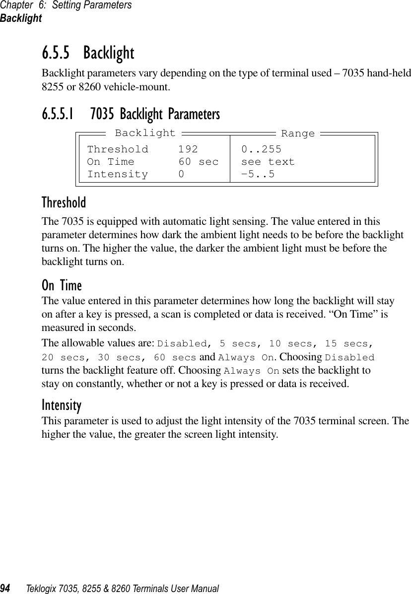
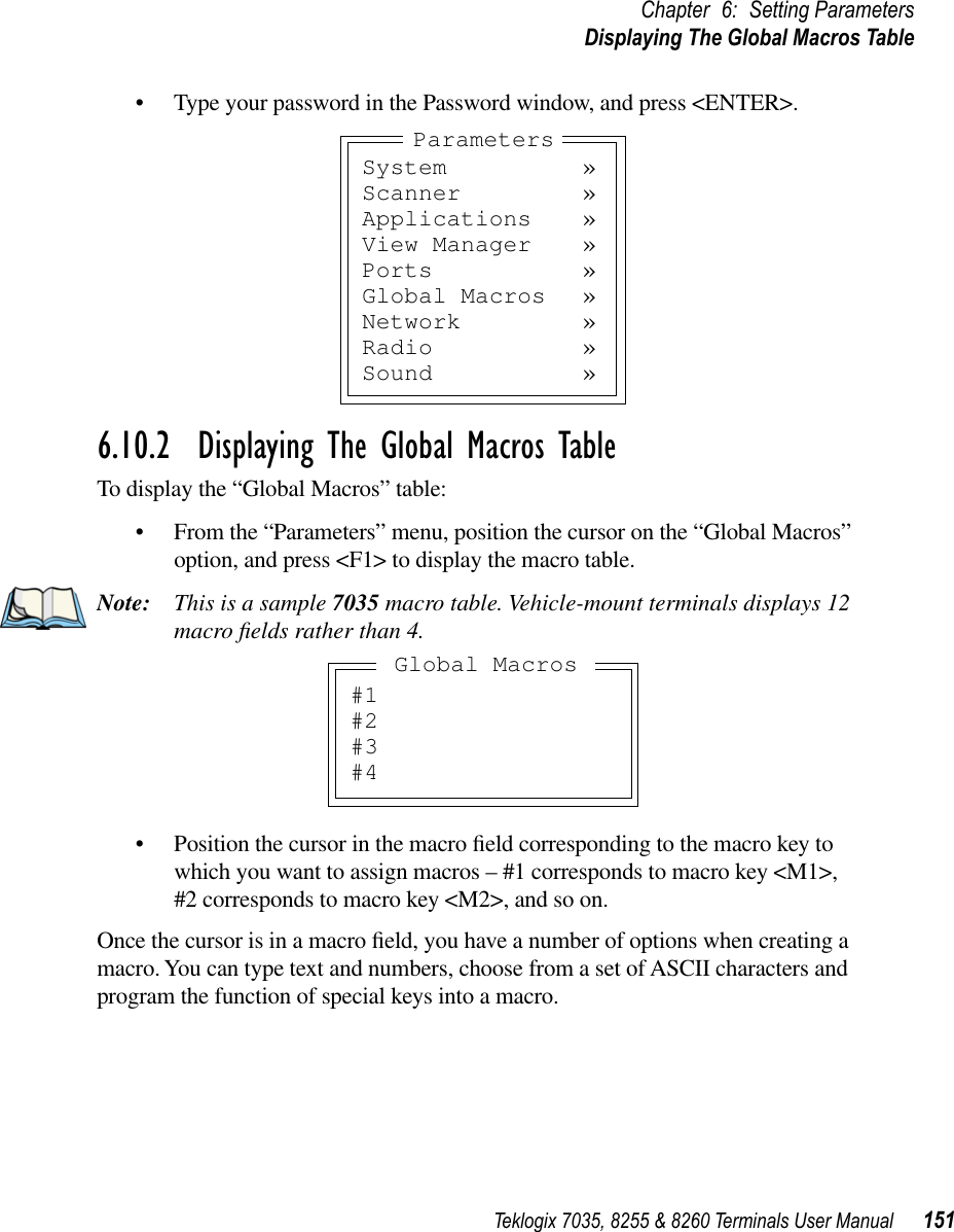
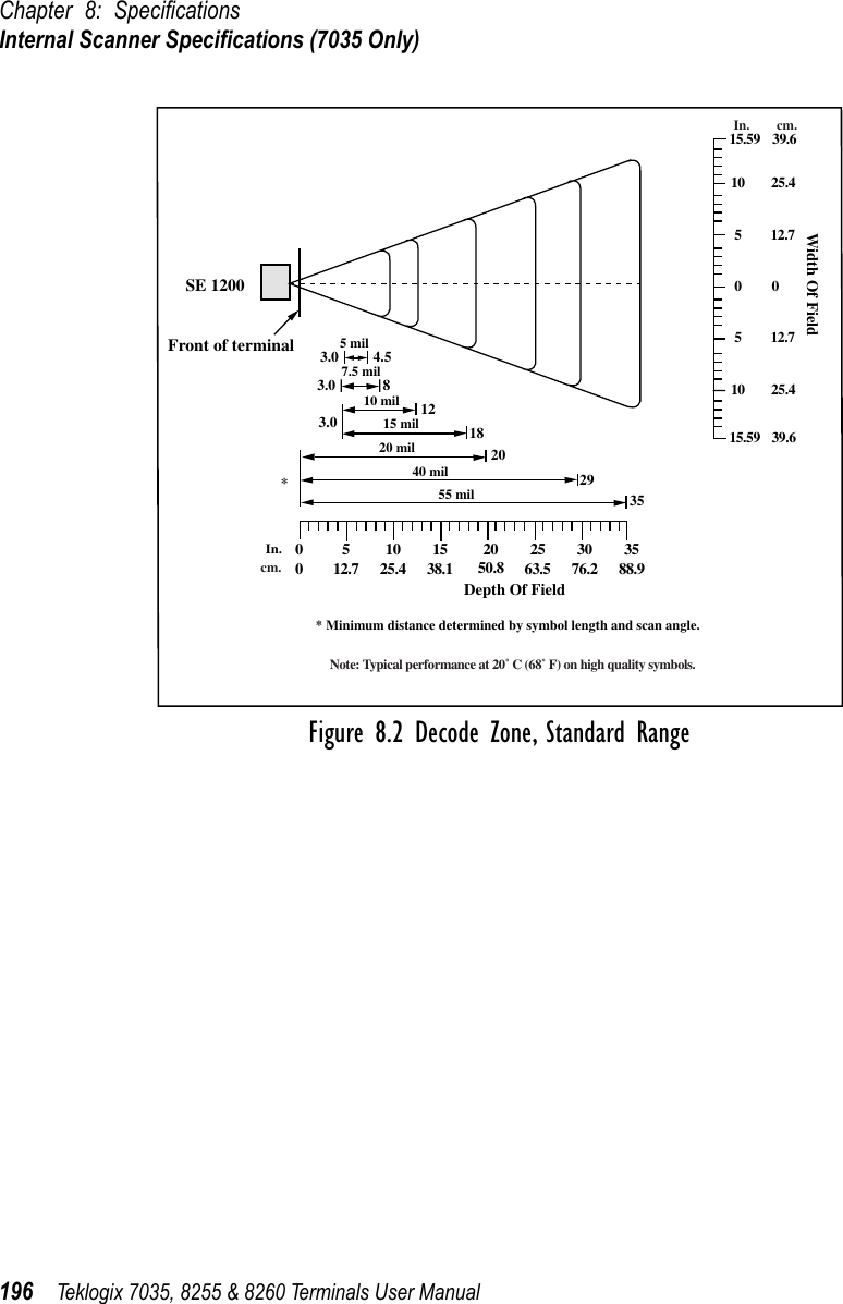
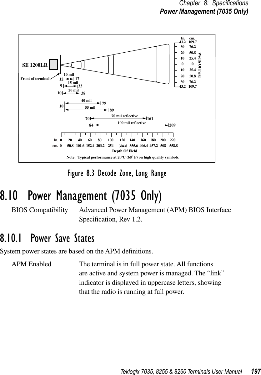
7035 8255 8260 User Manual

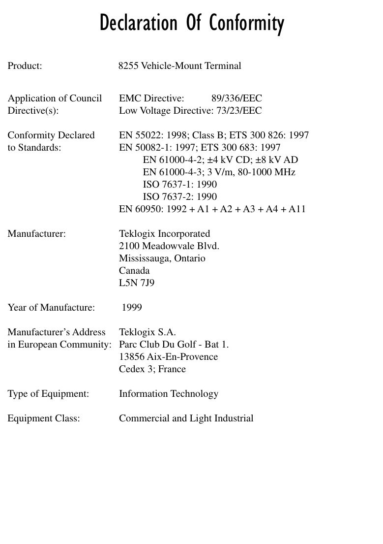

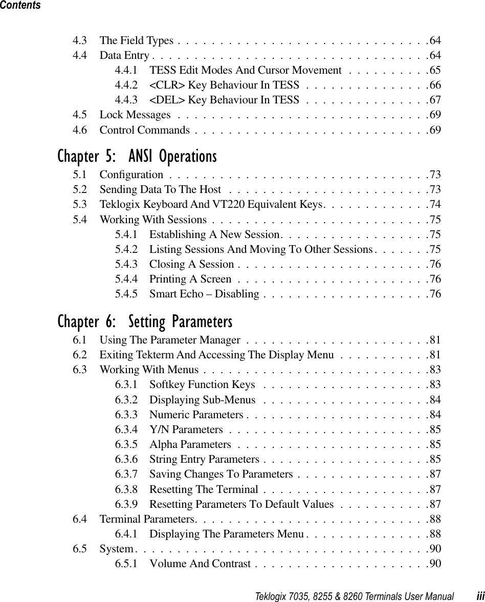
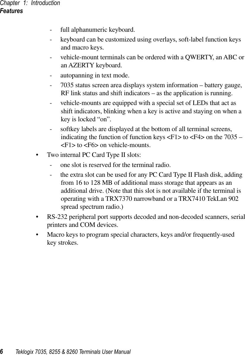
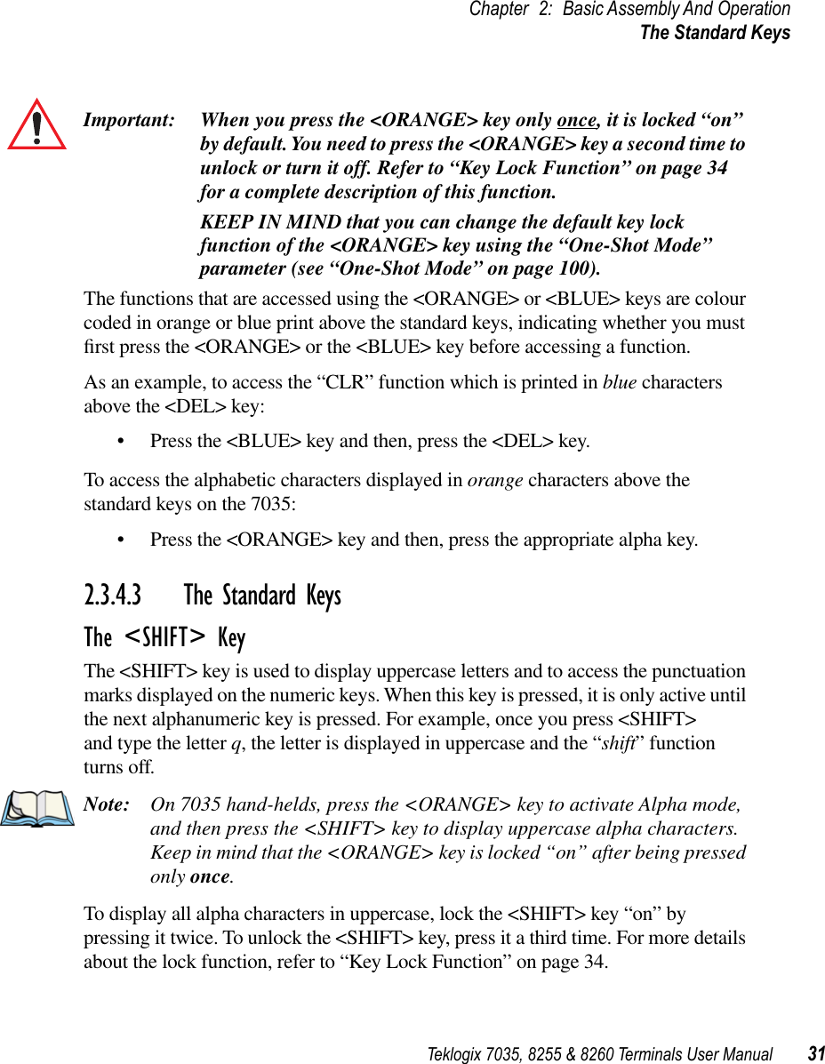
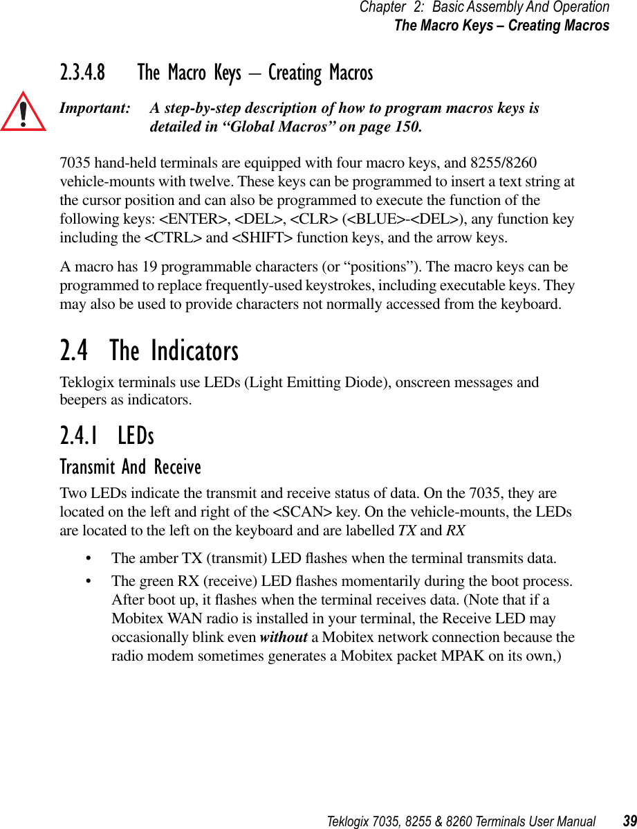

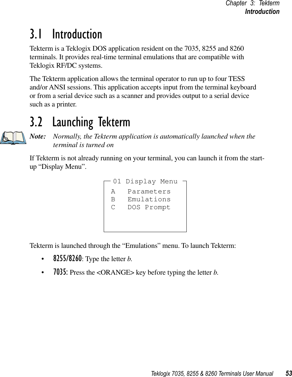
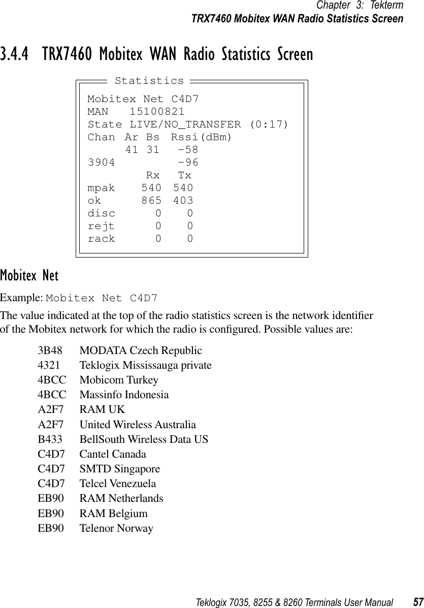
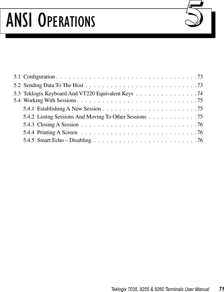
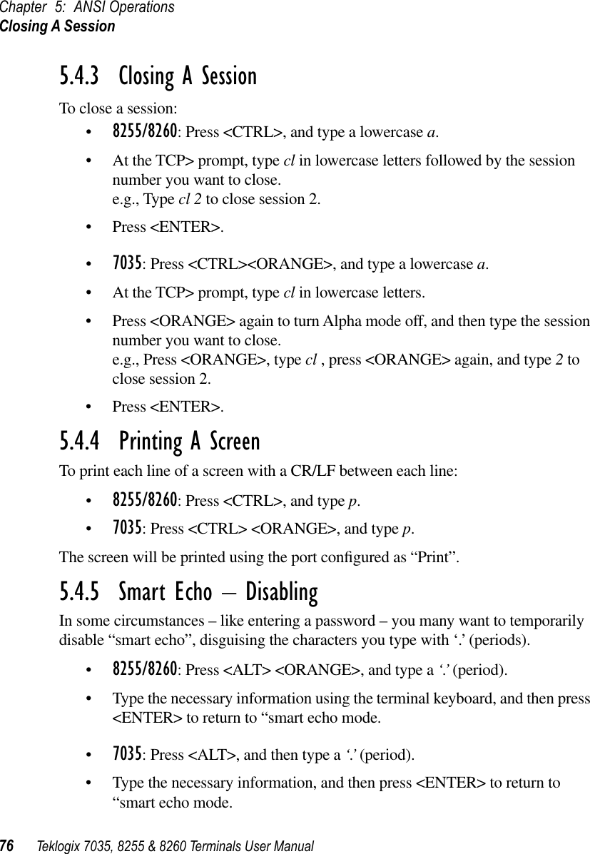
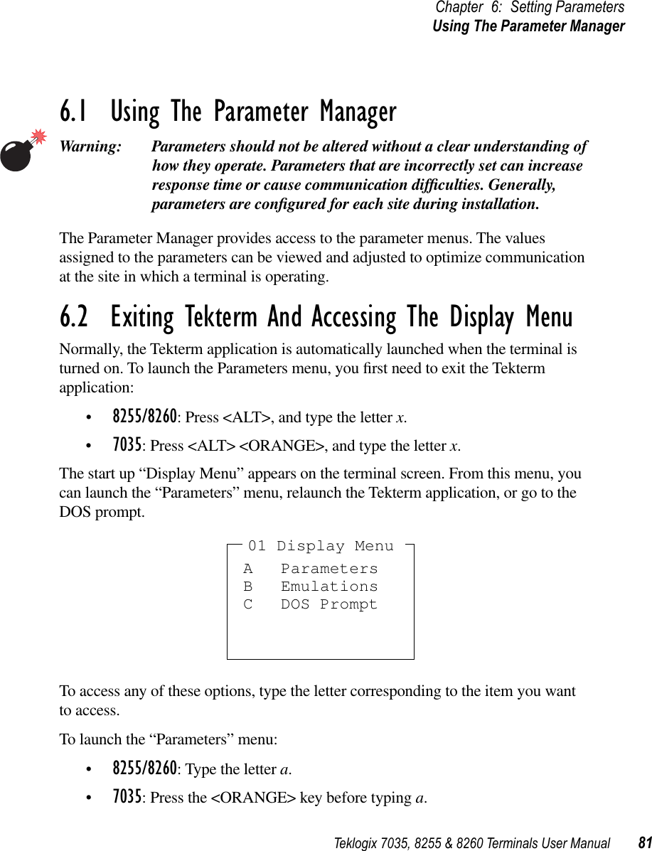
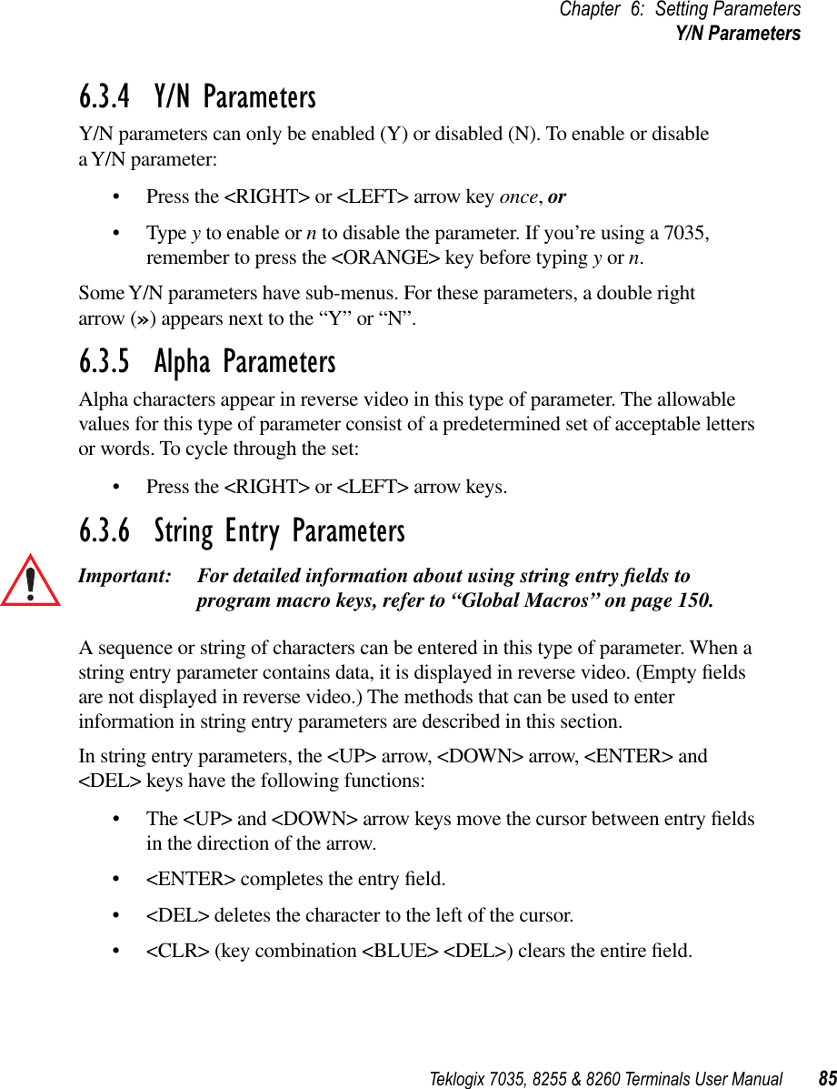
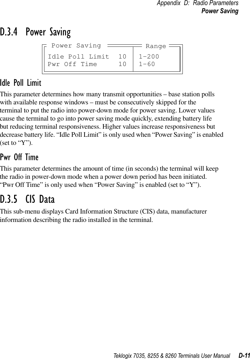
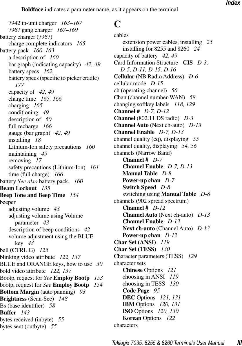
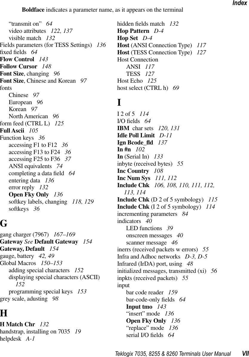
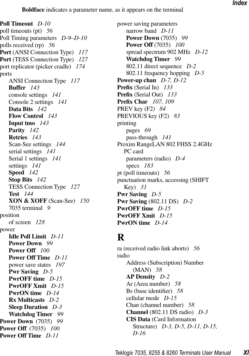
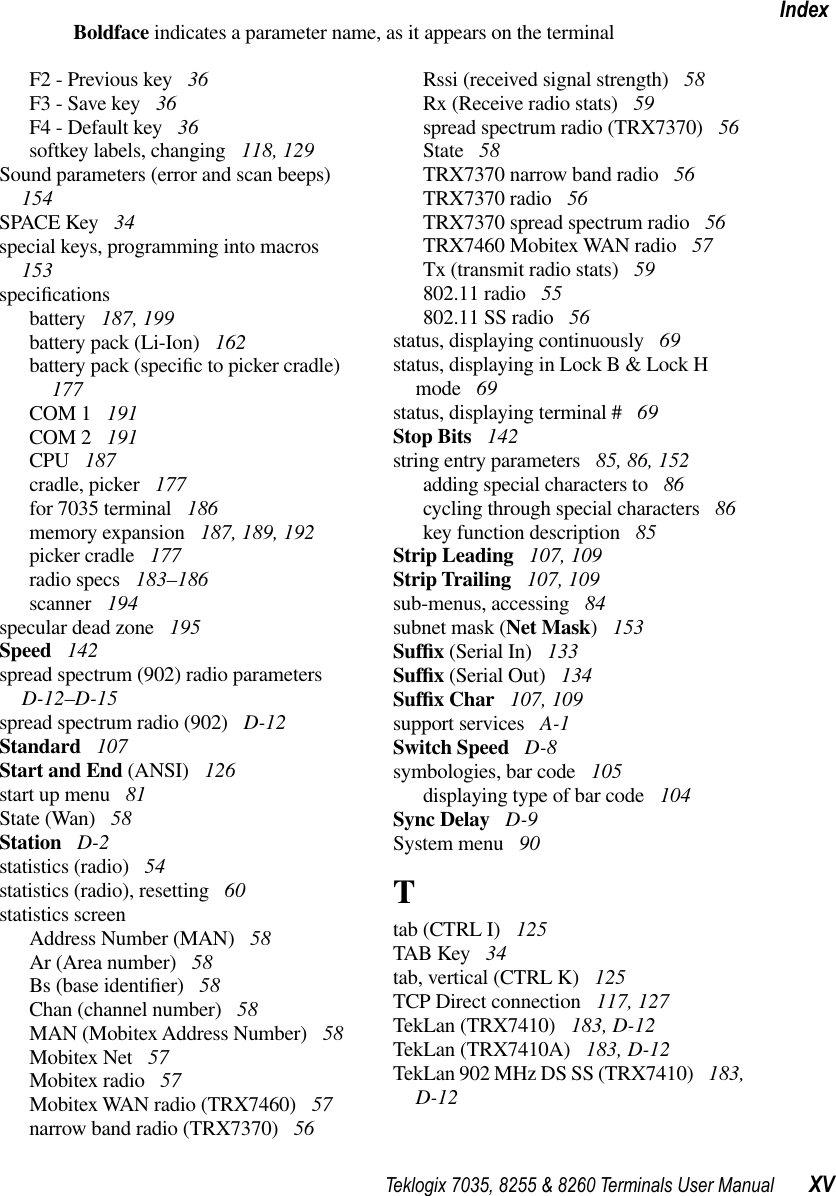
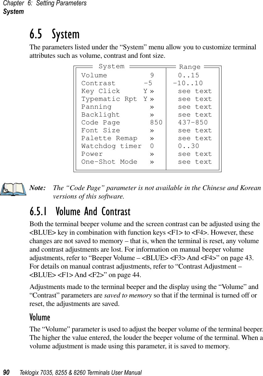
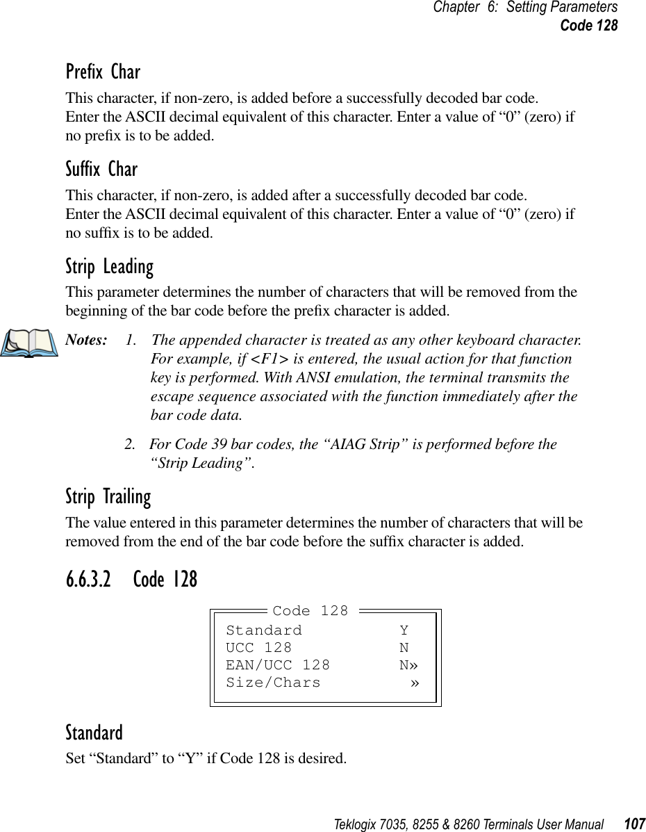
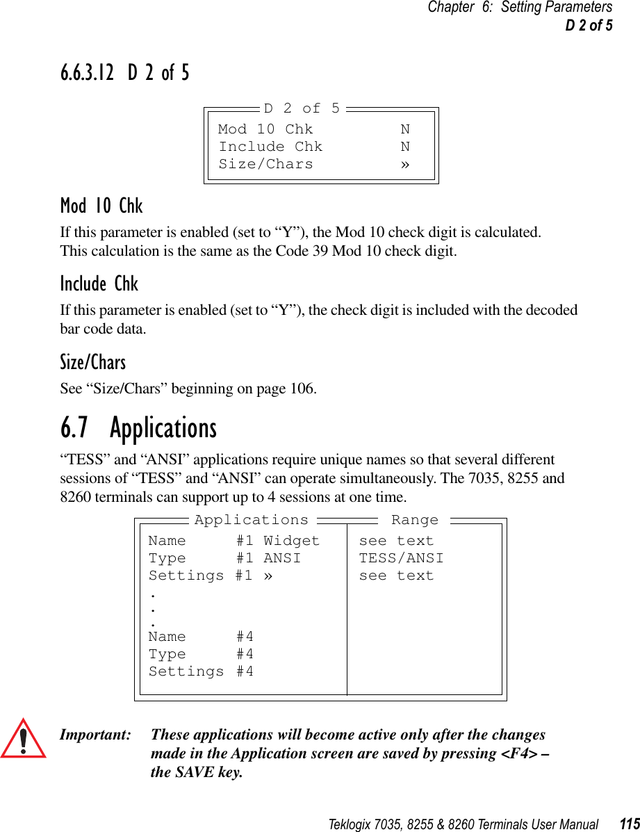
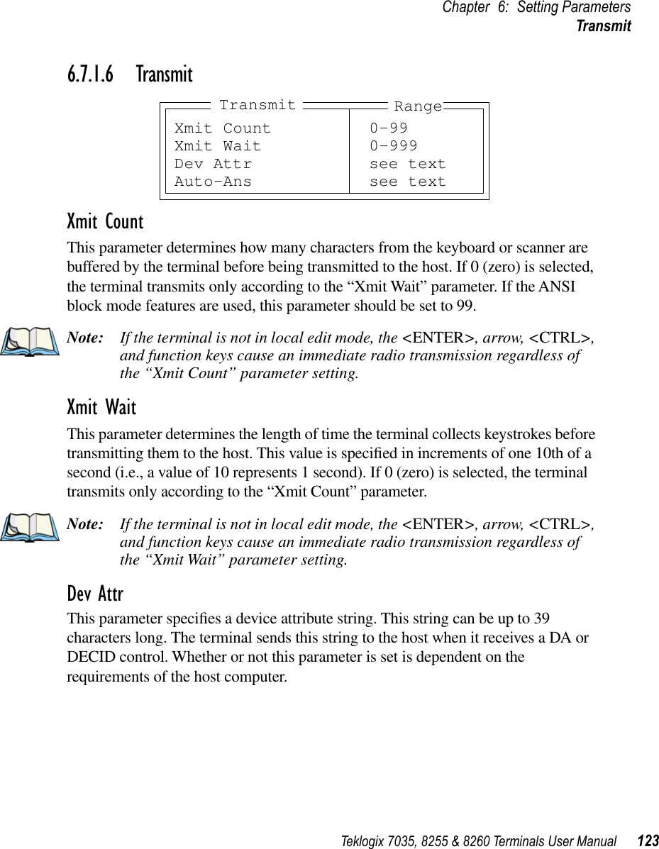
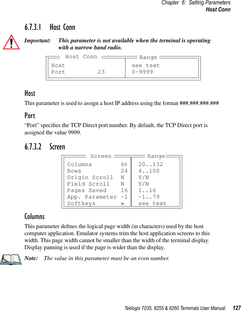
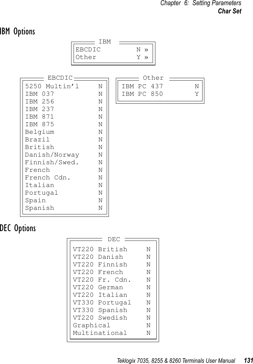
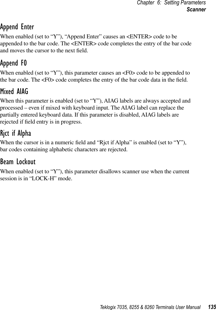
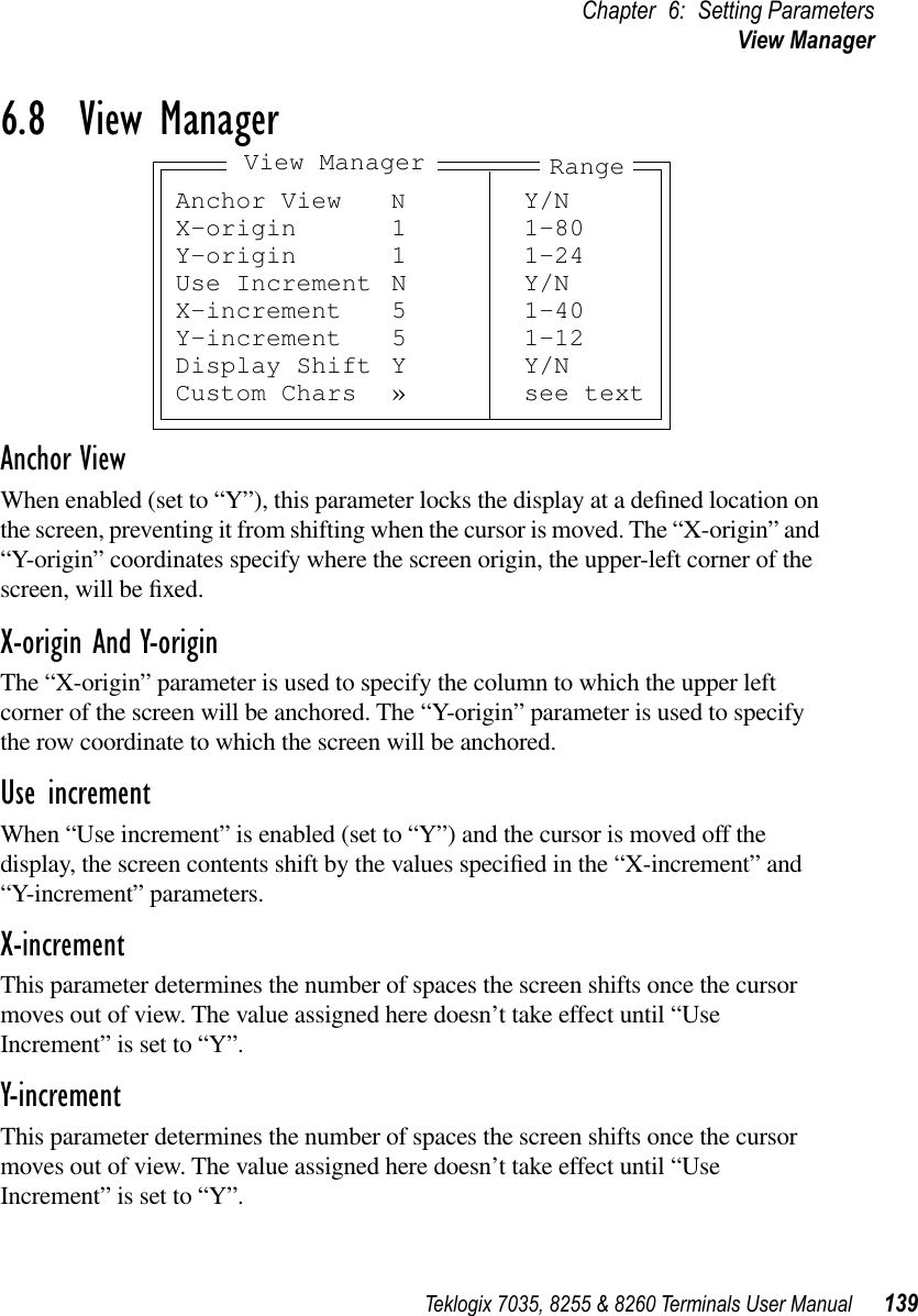
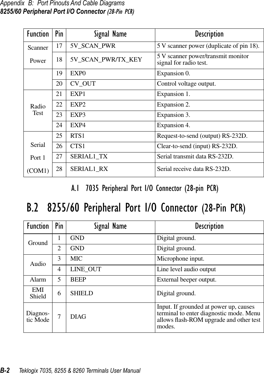
![Chapter 6: Setting ParametersChoosing An ASCII Character With The Arrow Keys86 Teklogix 7035, 8255 & 8260 Terminals User Manual6.3.6.1 Choosing An ASCII Character With The Arrow KeysImportant: Make sure the <CTRL> and <SHIFT> keys are turned off! By pressing either the <RIGHT> or <LEFT> arrow key, you can cycle through a set of printable characters not directly accessible from the keyboard. The ASCII sets differ slightly depending on the type of terminal you’re using.7035: / < > % ^ & ` ~ | [ ] { } " ' ? = + ;8255/8260: ^ & ‘ ~ | [ ] { } ’ " •Press the <RIGHT> arrow to display the next character in this sequence, and the <LEFT> arrow to display the previous one.6.3.6.2 Adding Additional ASCII CharactersWhen you’ve chosen an ASCII character and want to add another one in the same field, the cursor must be moved to the right of the existing character. Normally, pressing the <RIGHT> arrow key moves the cursor to the right, but in a string entry field, pressing the <RIGHT> arrow key cycles through the available ASCII characters instead. If you’ve already chosen an ASCII character and want to add another one in the field, you need to take a few extra steps to move the cursor to the right.To add another ASCII character in the string entry field, next to the one you’ve already chosen:•Type a numeric character – for example, type the number 7.•Next, press the <DEL> keyThe cursor is now positioned to the right of the previously selected ASCII character.•Press the <RIGHT> or <LEFT> arrow key to scroll through the ASCII characters, and select another character.6.3.6.3 Entering Information In A String Entry FieldIn addition to using the fixed set of ASCII values assigned to this type of parameter, you can also type text in a string entry field.•Type the required text in the string entry field – including letters, numbers and symbols.•Press <ENTER> to save the text.](https://usermanual.wiki/Psion/WLPC24H.7035-8255-8260-User-Manual/User-Guide-92261-Page-106.png)
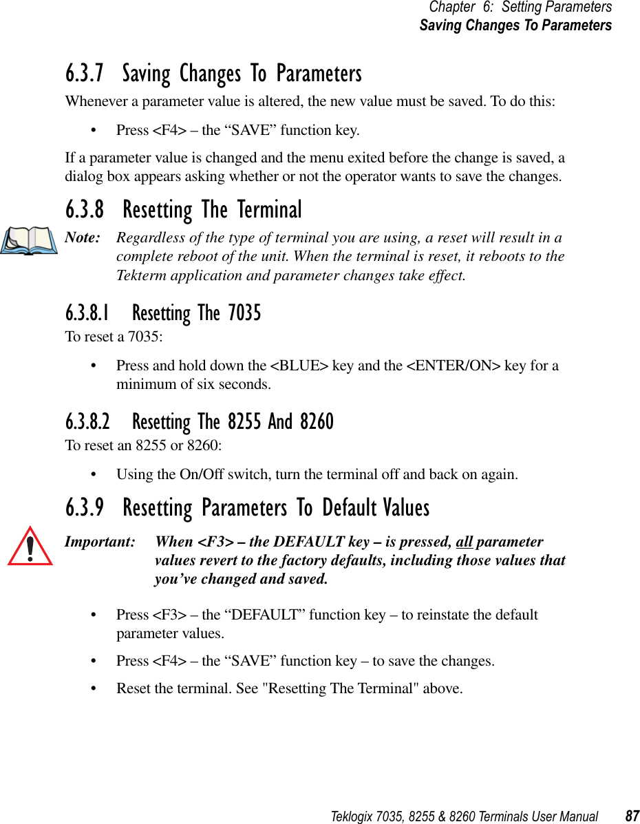
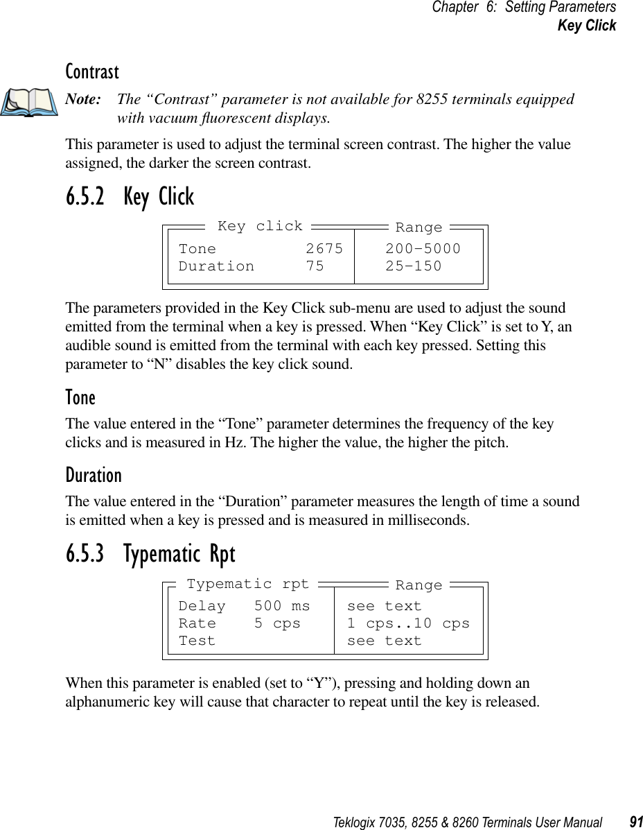
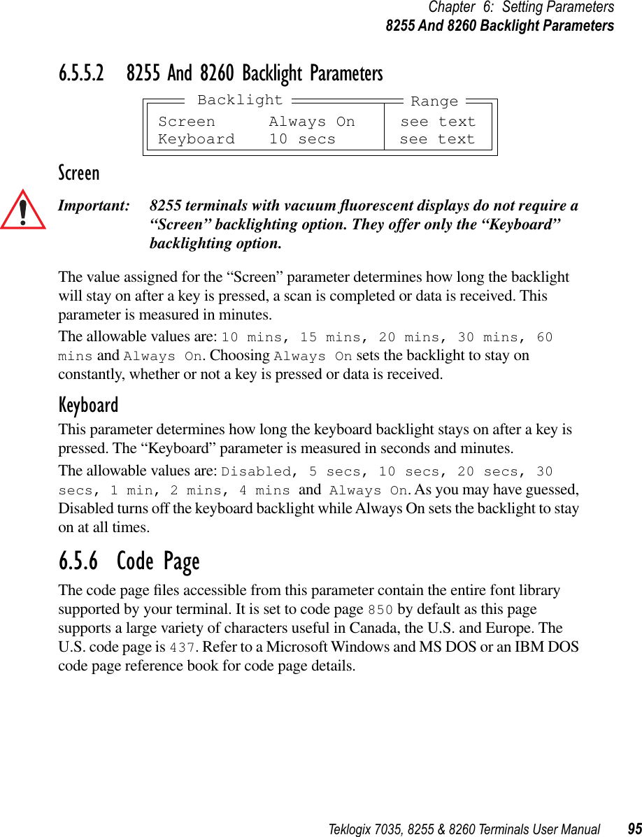
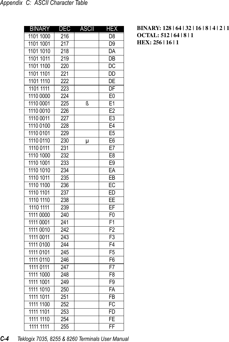
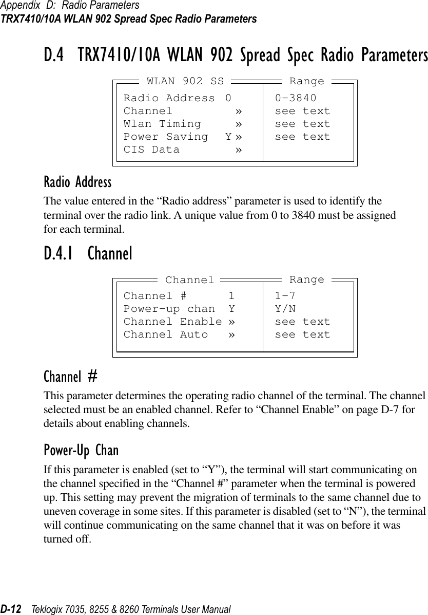
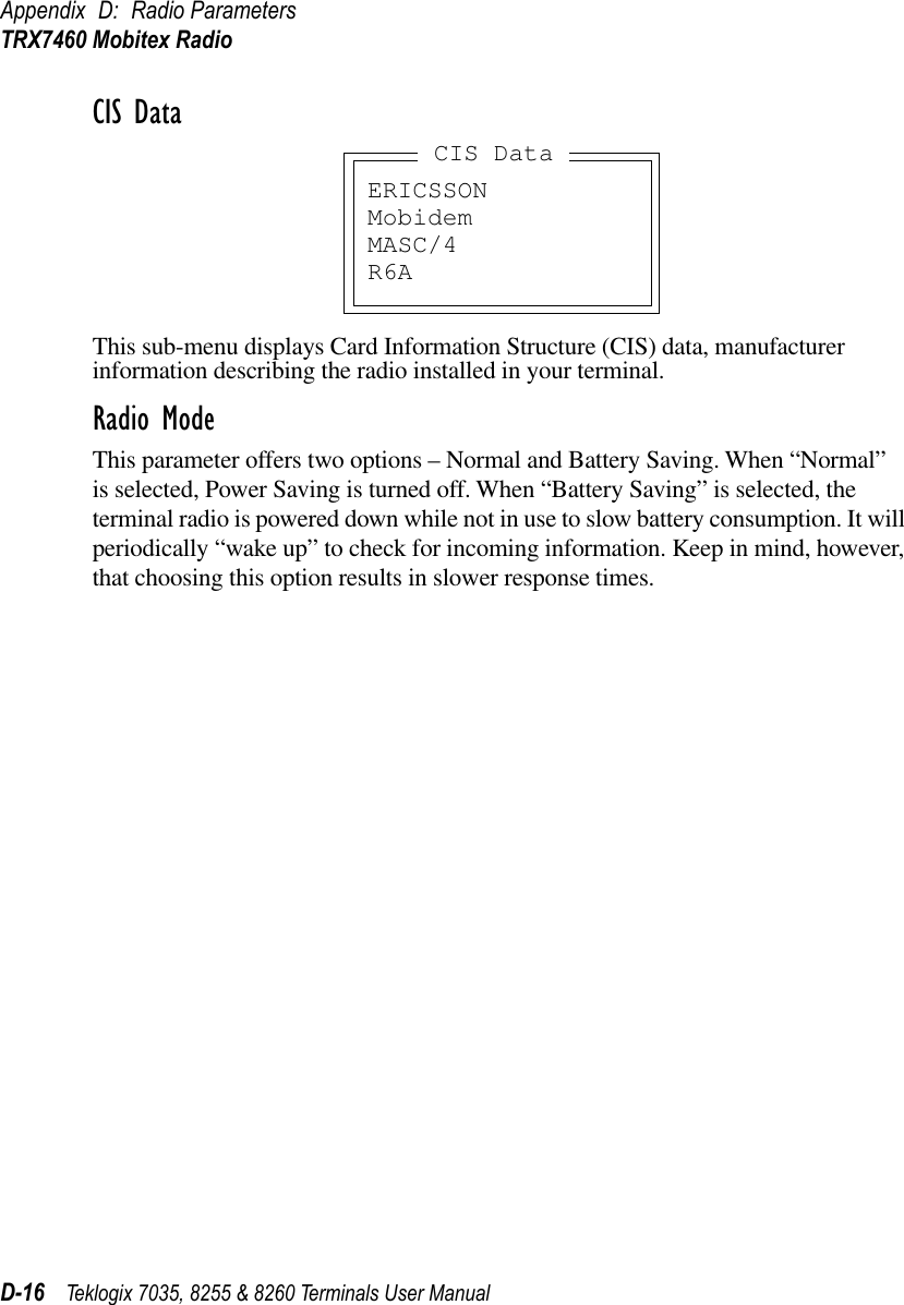
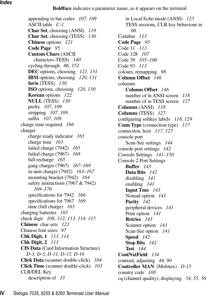
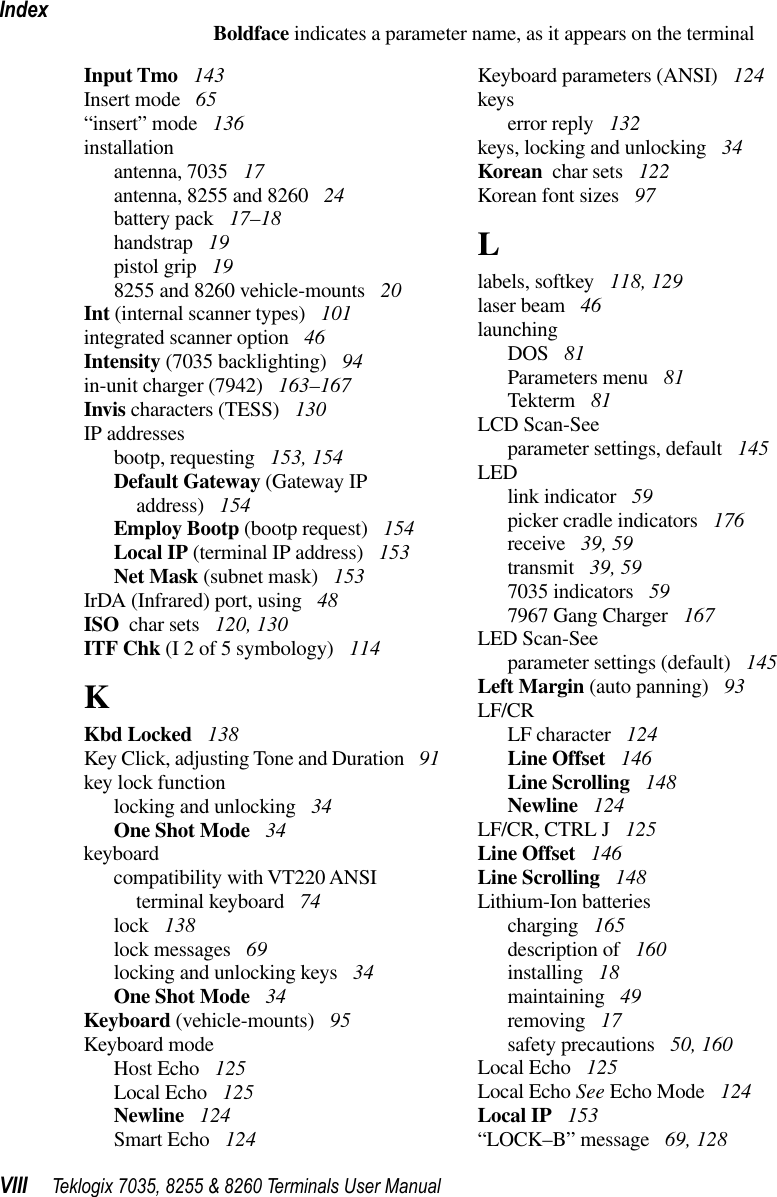
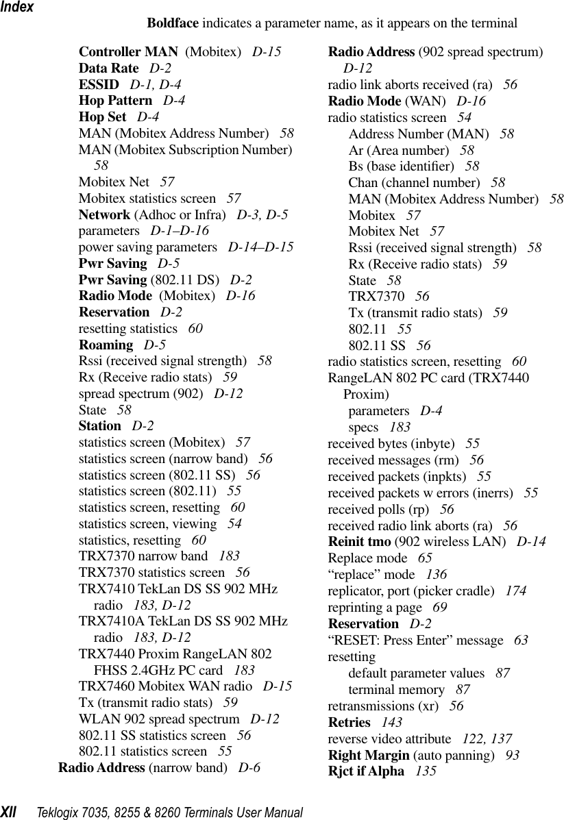
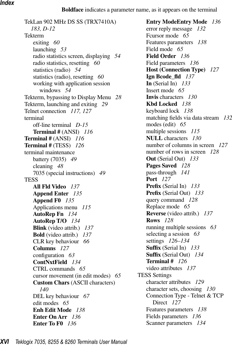
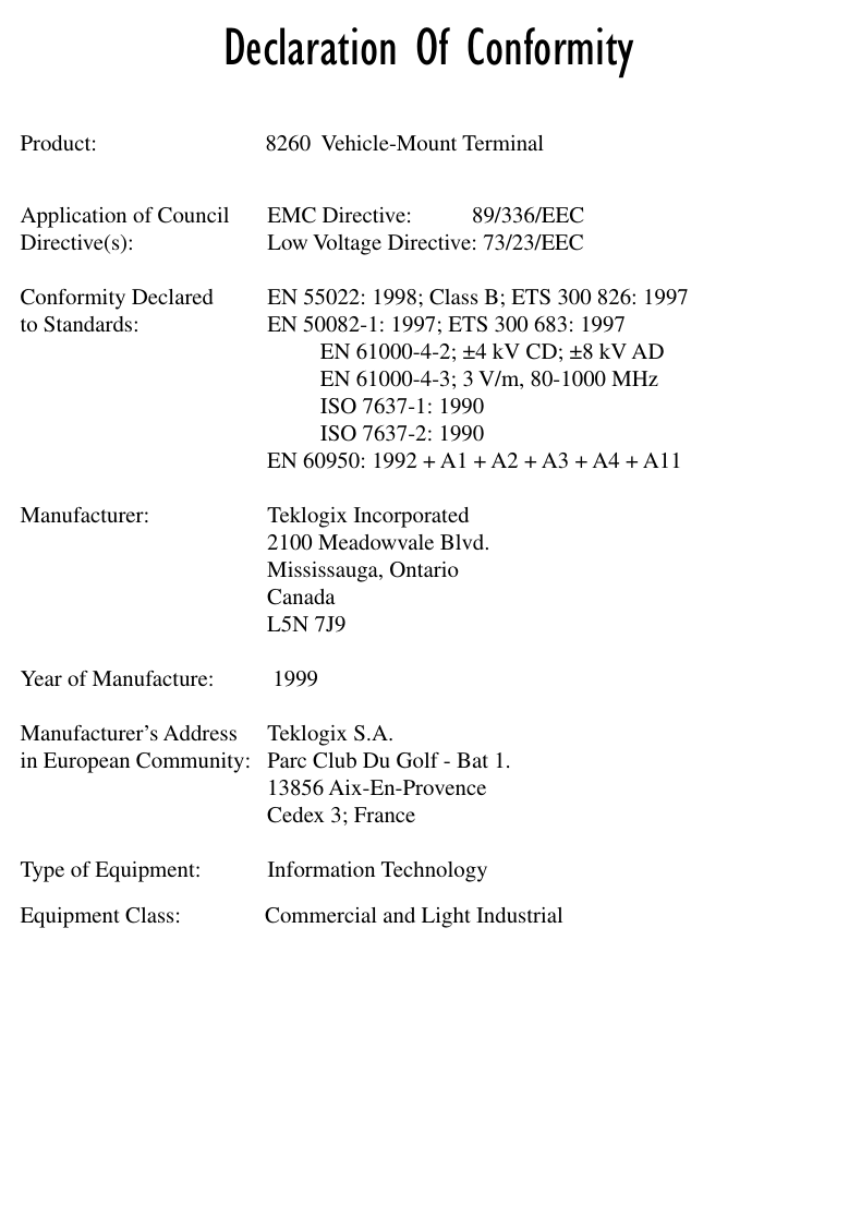
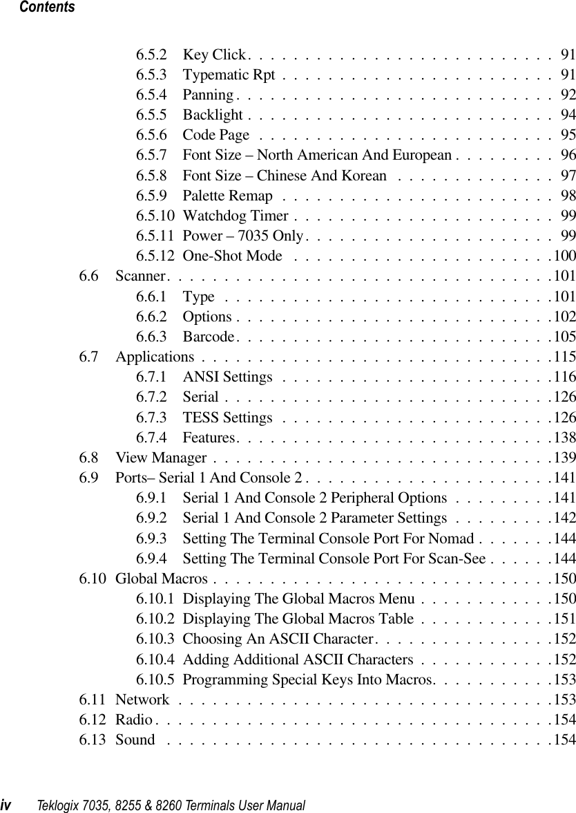
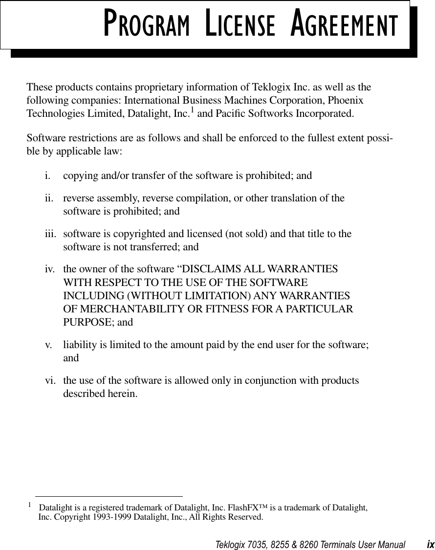
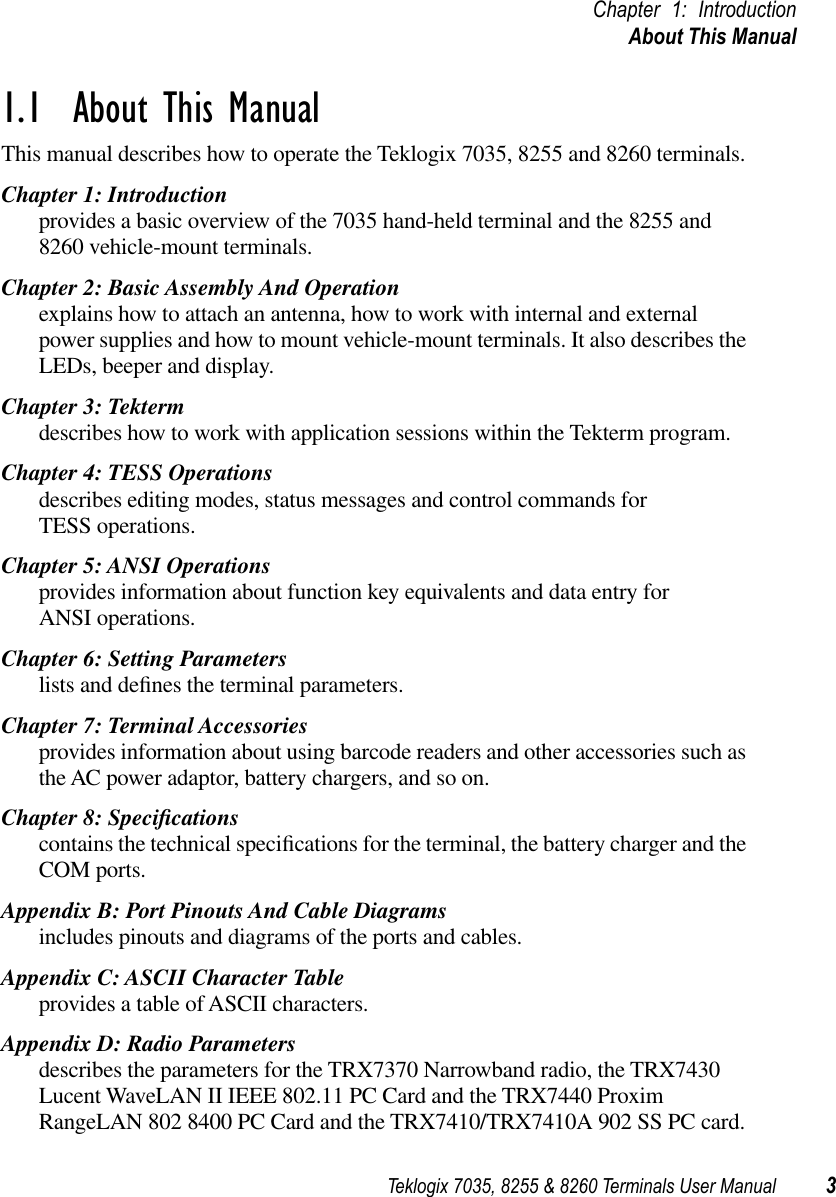
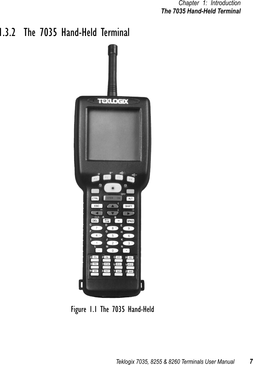
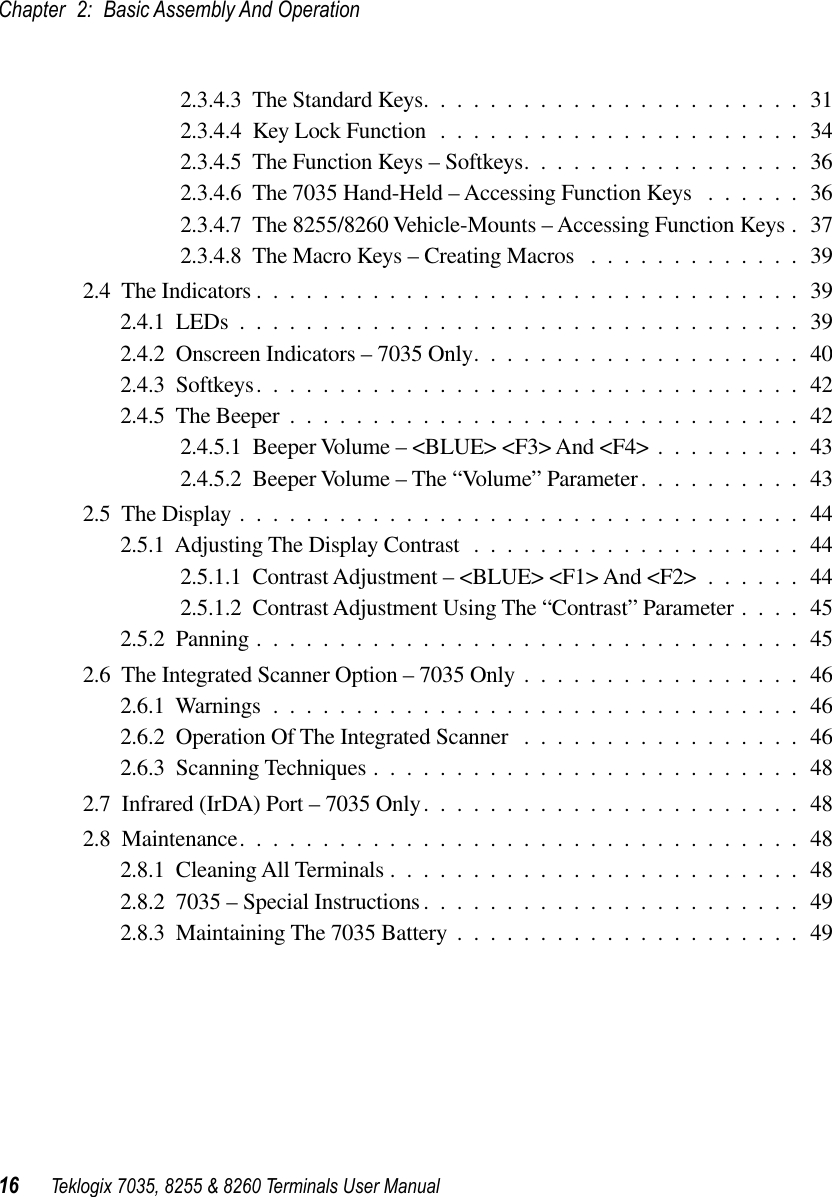
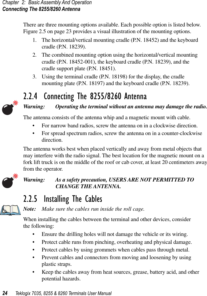
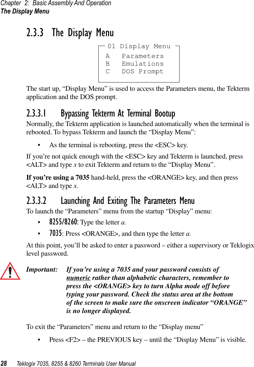
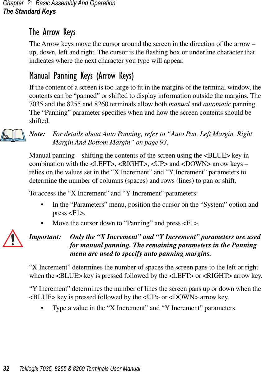
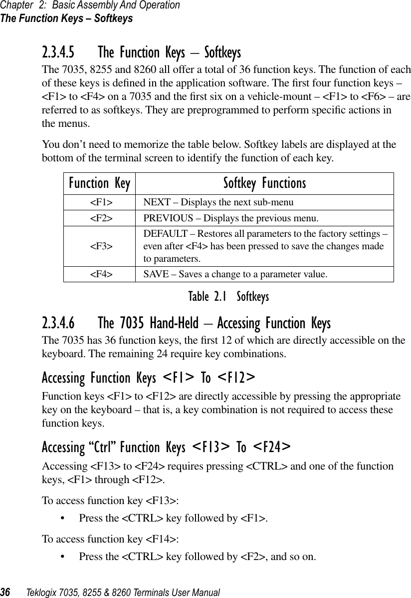
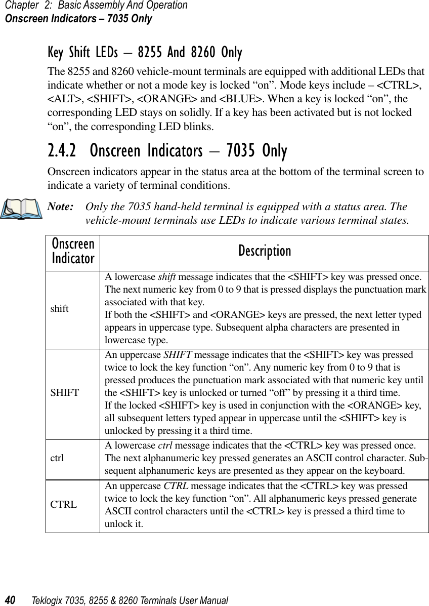
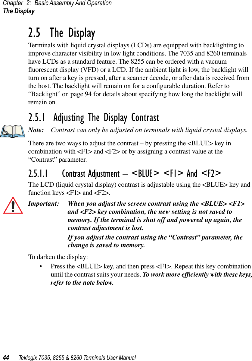
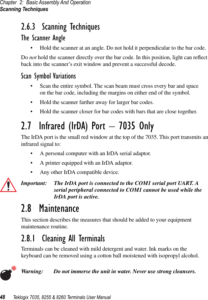
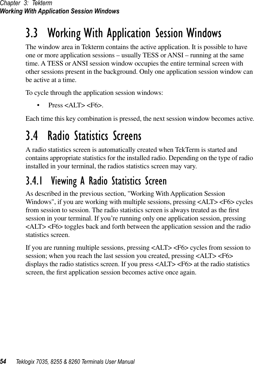
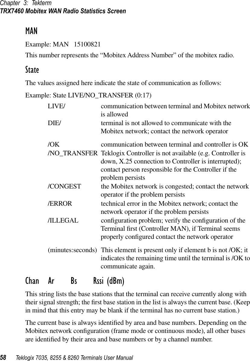
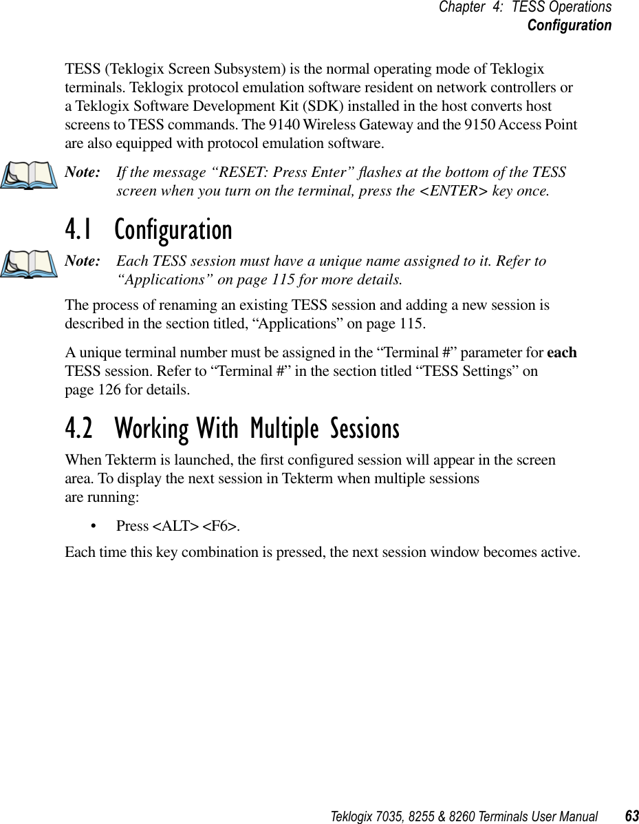
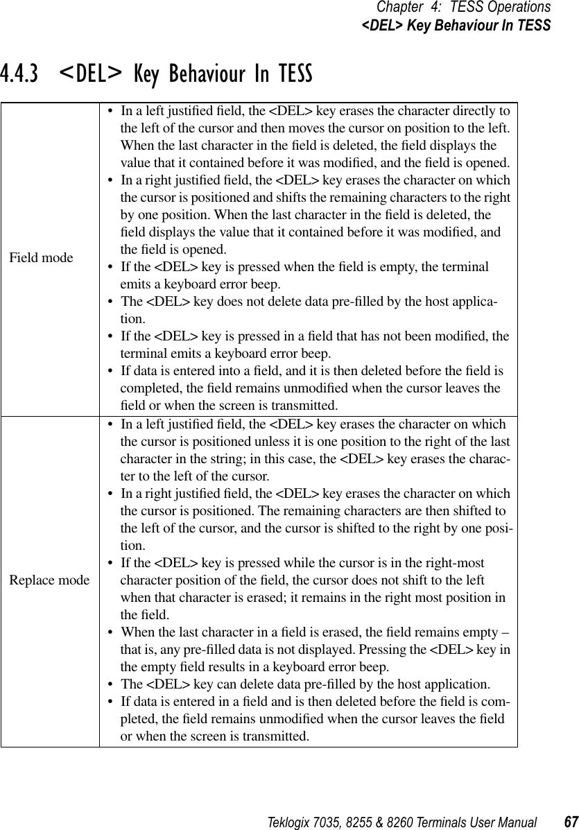
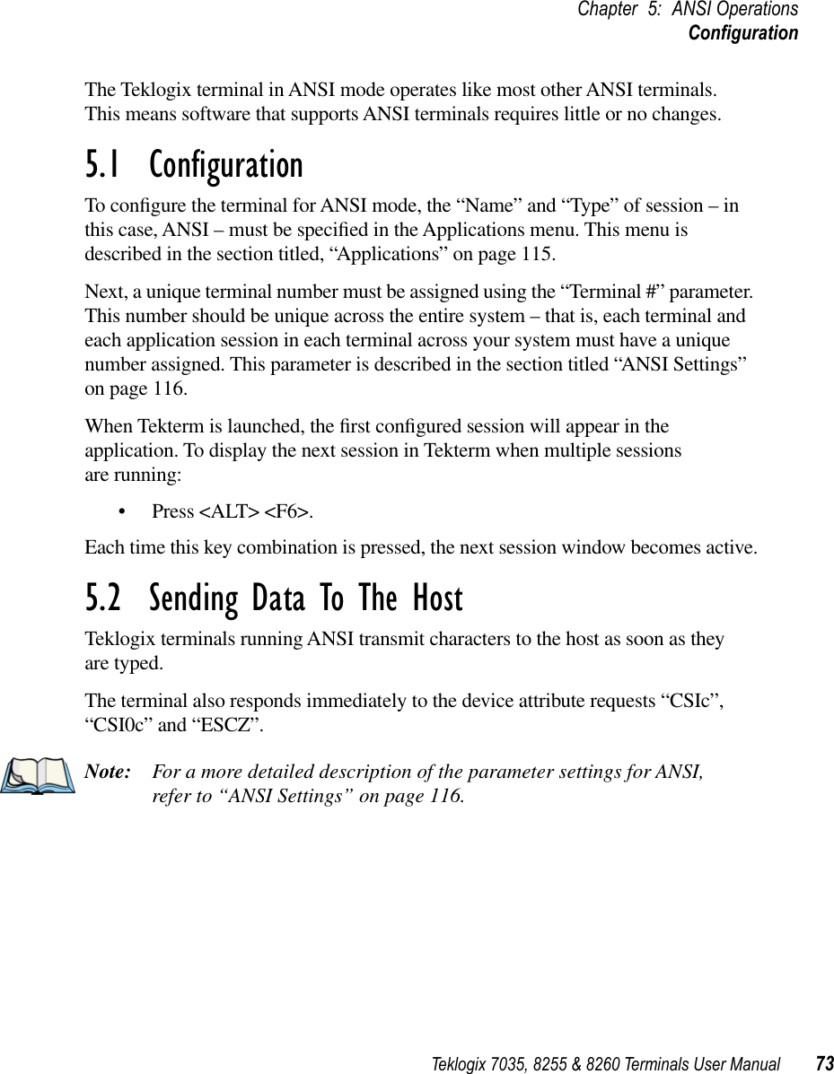
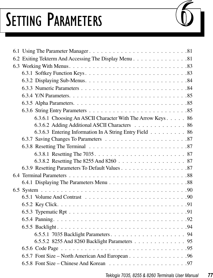
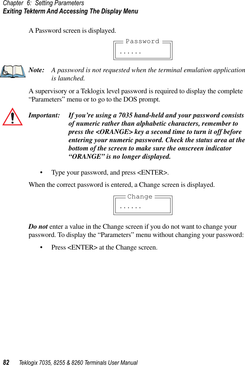
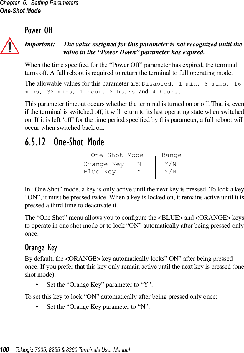
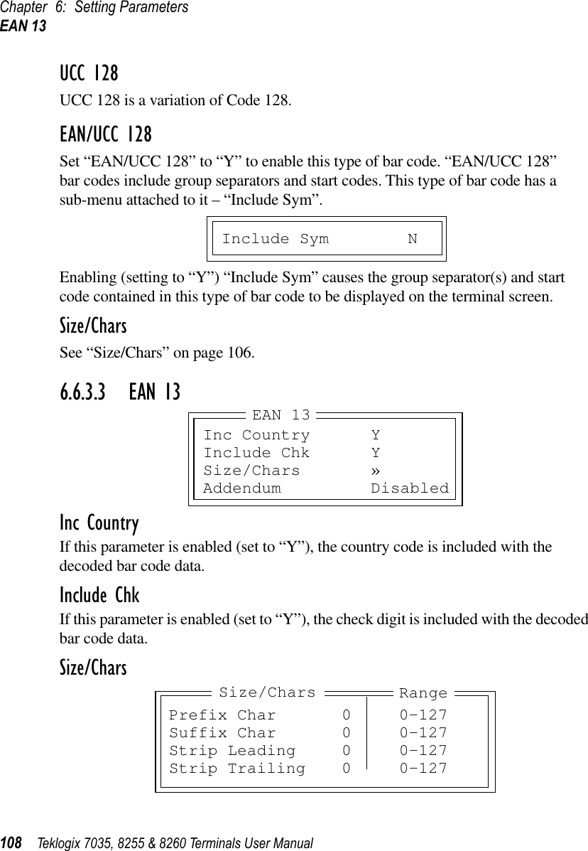
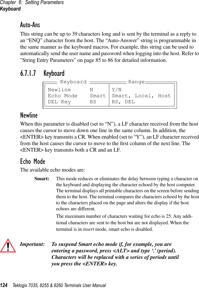
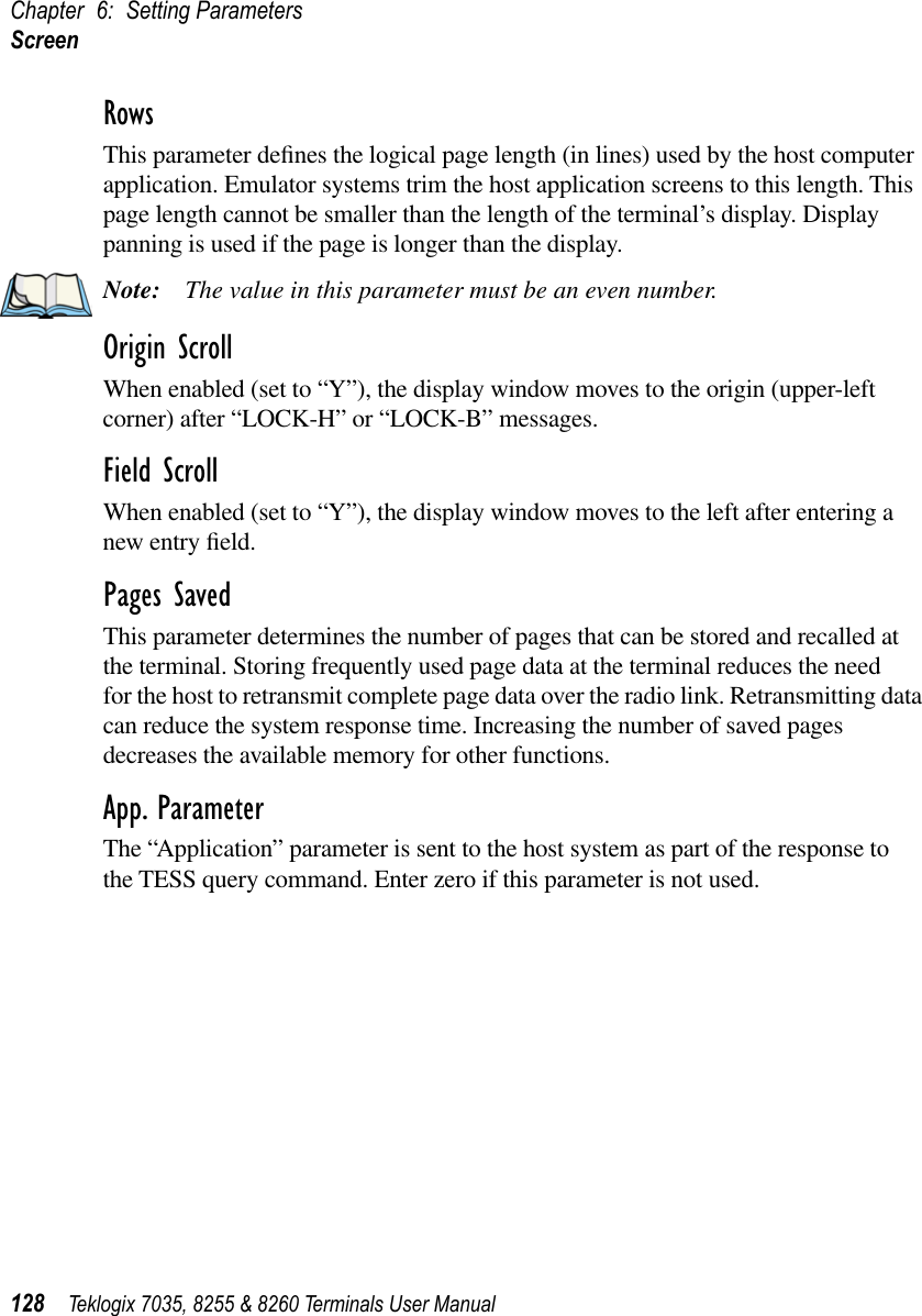
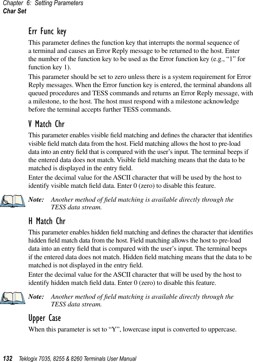
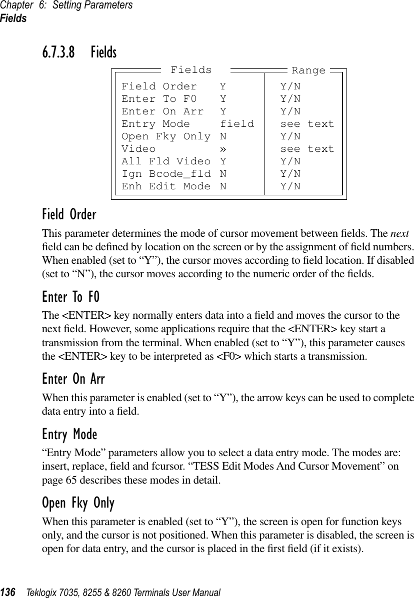
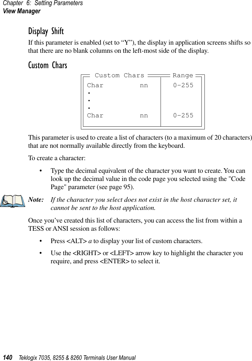
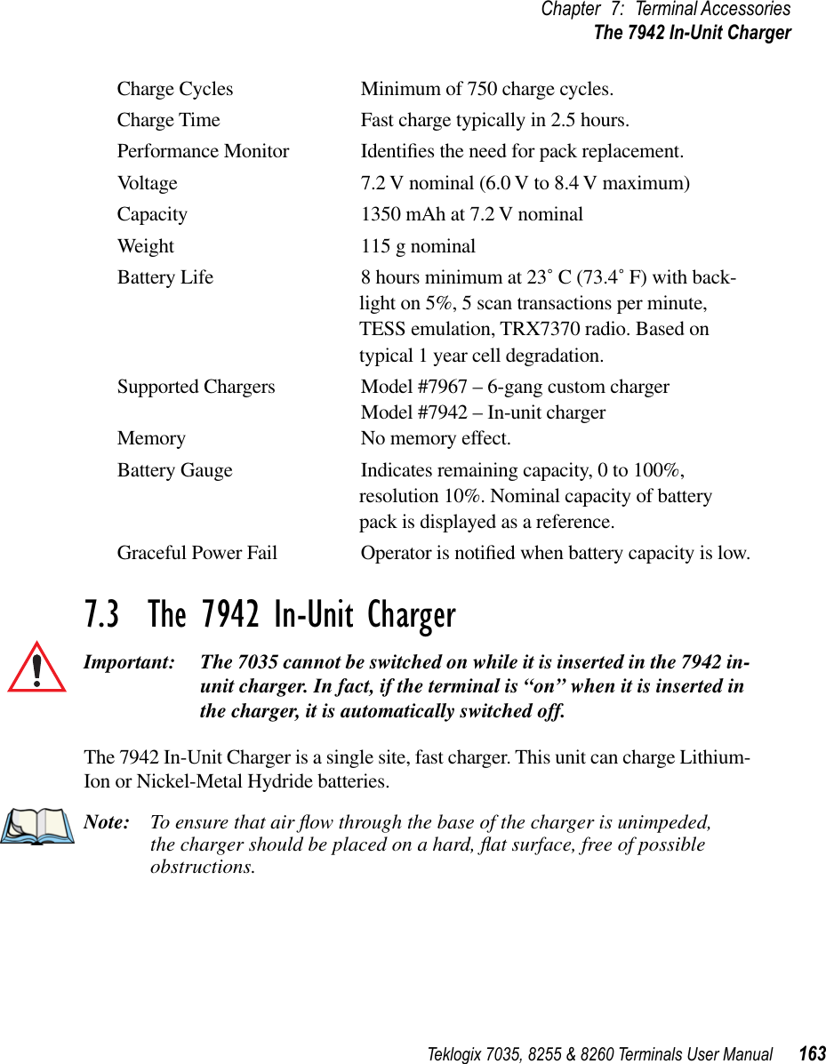
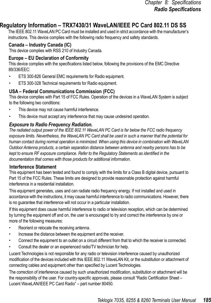
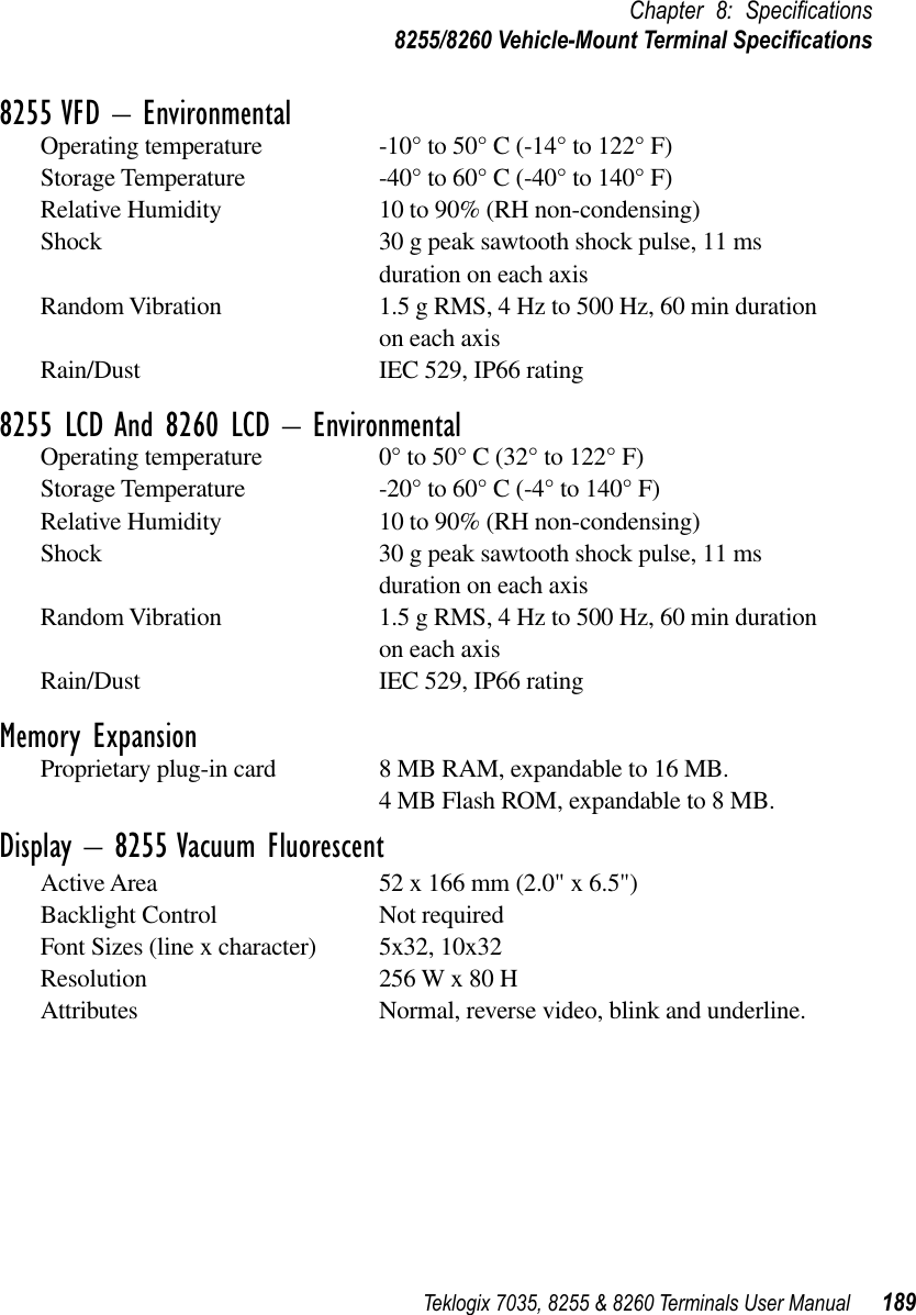
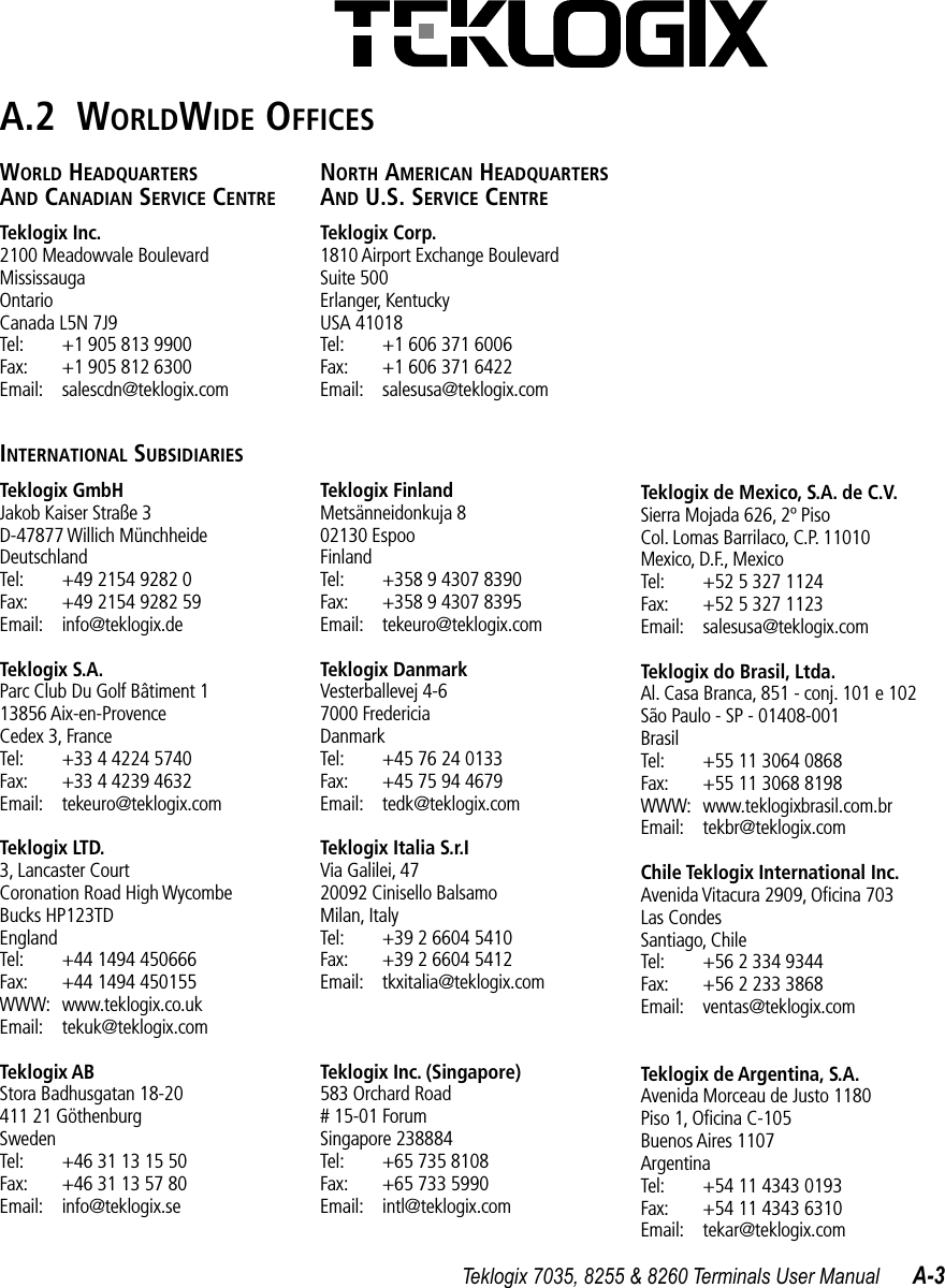
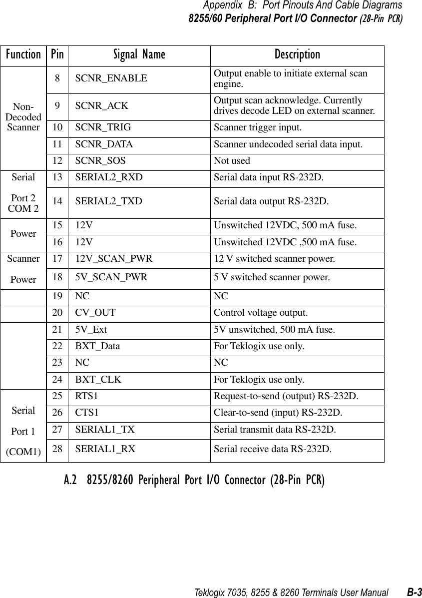
![Chapter 6: Setting ParametersPalette Remap98 Teklogix 7035, 8255 & 8260 Terminals User Manual7035 Fonts6.5.9 Palette RemapA DOS-based application generally uses a VGA colour palette. On Teklogix terminals, these colours are converted to grey scale with varying degrees of success. While grey scale displays well on a 7035 hand-held terminal, it does not display as well on an 8255 LCD or an 8260 vehicle-mount terminal. The “Palette Remap” parameter allows you to substitute default application colours with colours that will display well on your Teklogix terminal.Note: All built-in Teklogix software uses only intense white (VGA index 15) and black (VGA index 0), both of which display well on Teklogix terminals.The values on the left-hand side of the “Palette Remap” screen represent the original VGA palette; these values cannot be changed. The values on the right-hand side of this screen can be altered to remap colours as they reach your Teklogix terminal display. For example, suppose that you want your terminal to always replace the colour red with the colour black. You need to change the red colour value of 4 to the black colour value of 0.Chinese Font Sizes7035 Korean Font Sizes70358x20 9x20[0] Black [0][1] Blue [1][2] Green [2][3] Cyan [3][4] Red [4][5] Magenta [5][6] Brown [6][7] Lt Grey [7][8] Dark Grey [8][9] Lt Blue [9][a] Lt Green [a][b] Lt Cyan [b][c] Lt Red [c][d] Lt Magenta [d][e] Yellow [e][f] White [f]Palette Remap](https://usermanual.wiki/Psion/WLPC24H.7035-8255-8260-User-Manual/User-Guide-92261-Page-118.png)
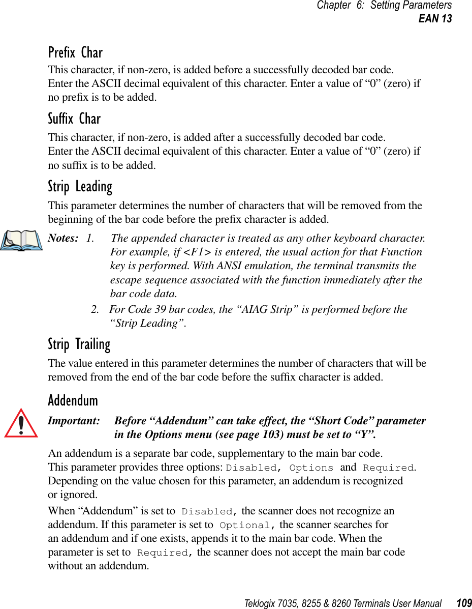
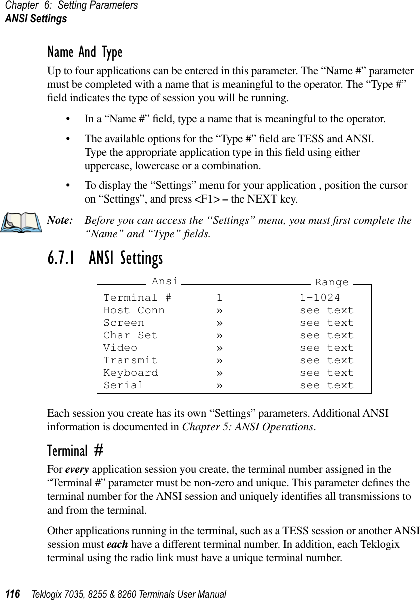
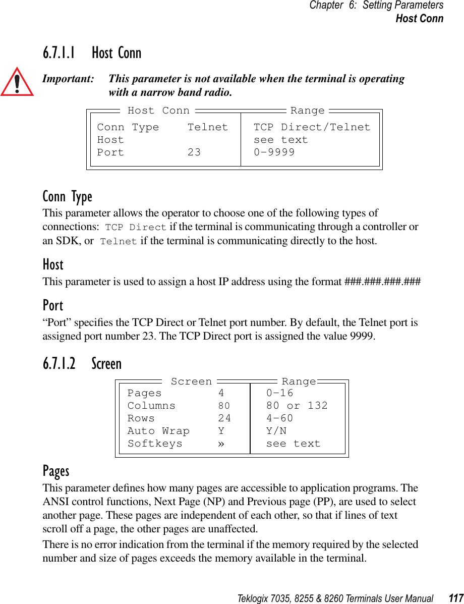
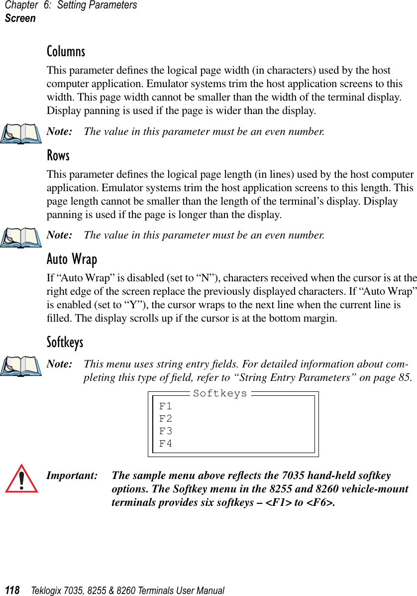
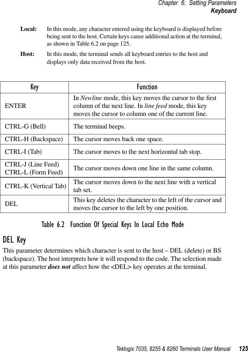
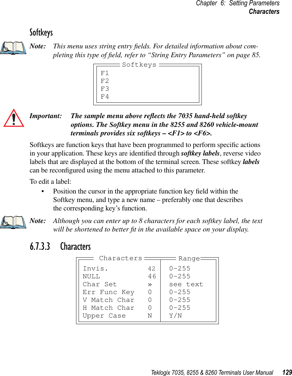
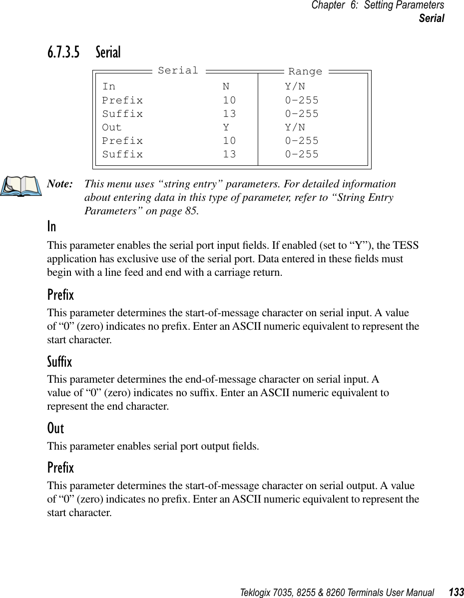
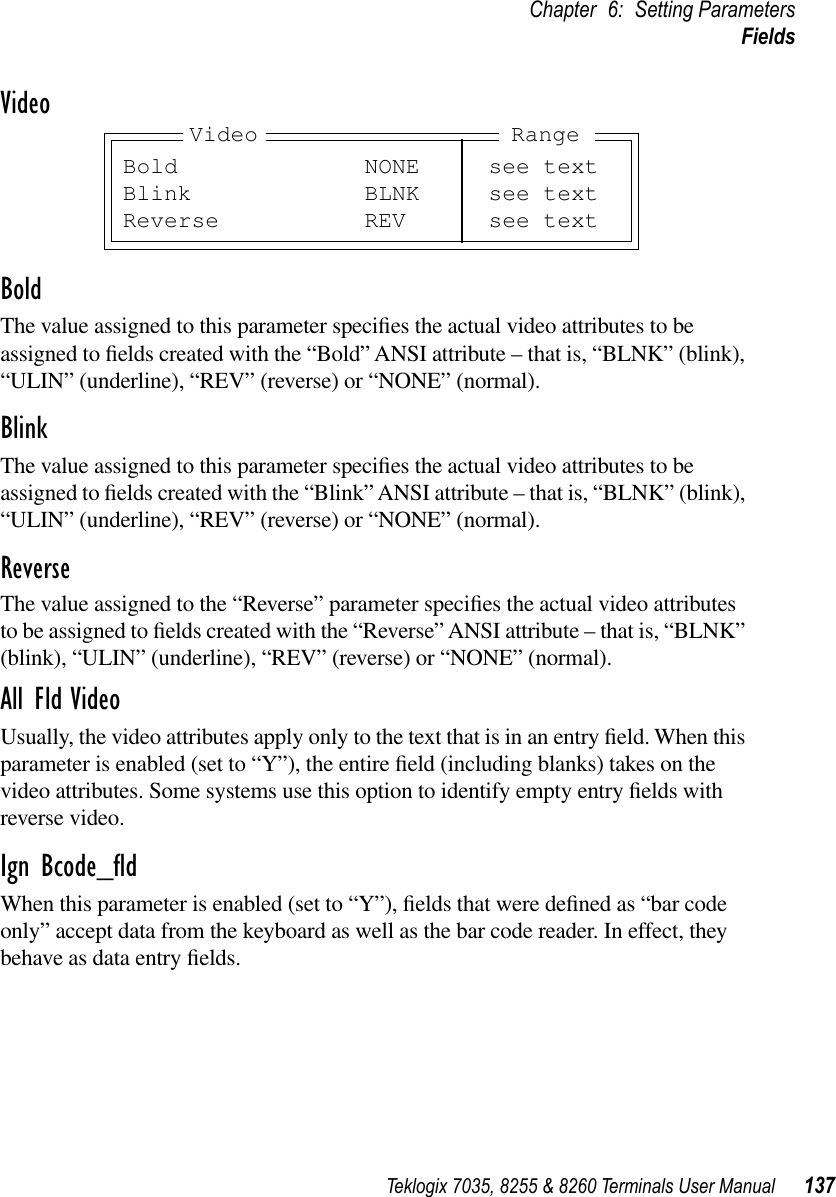
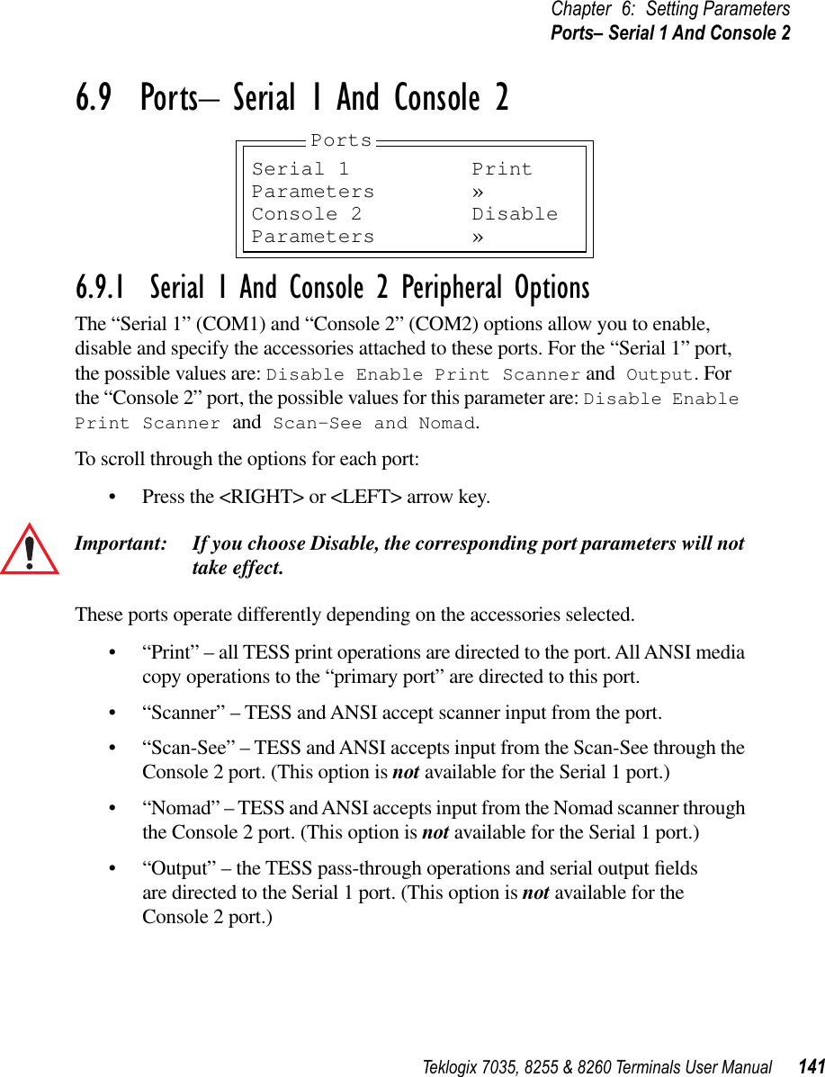
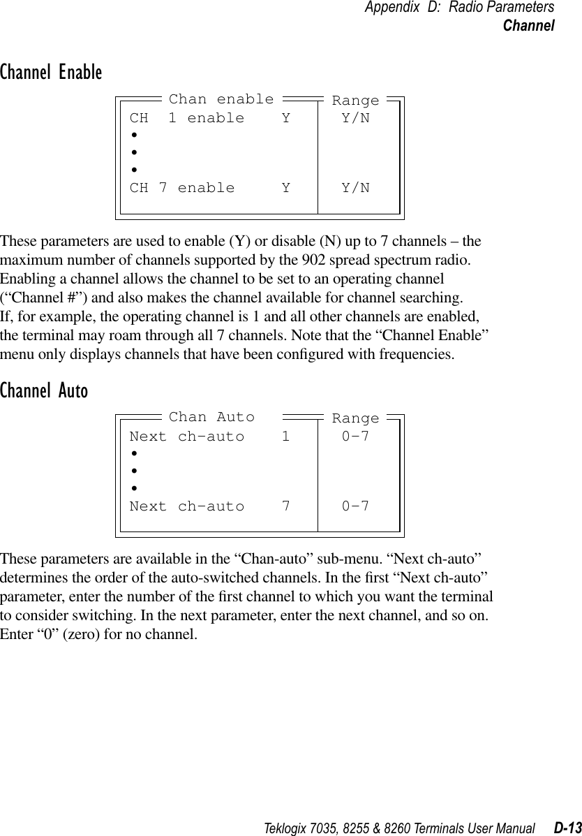
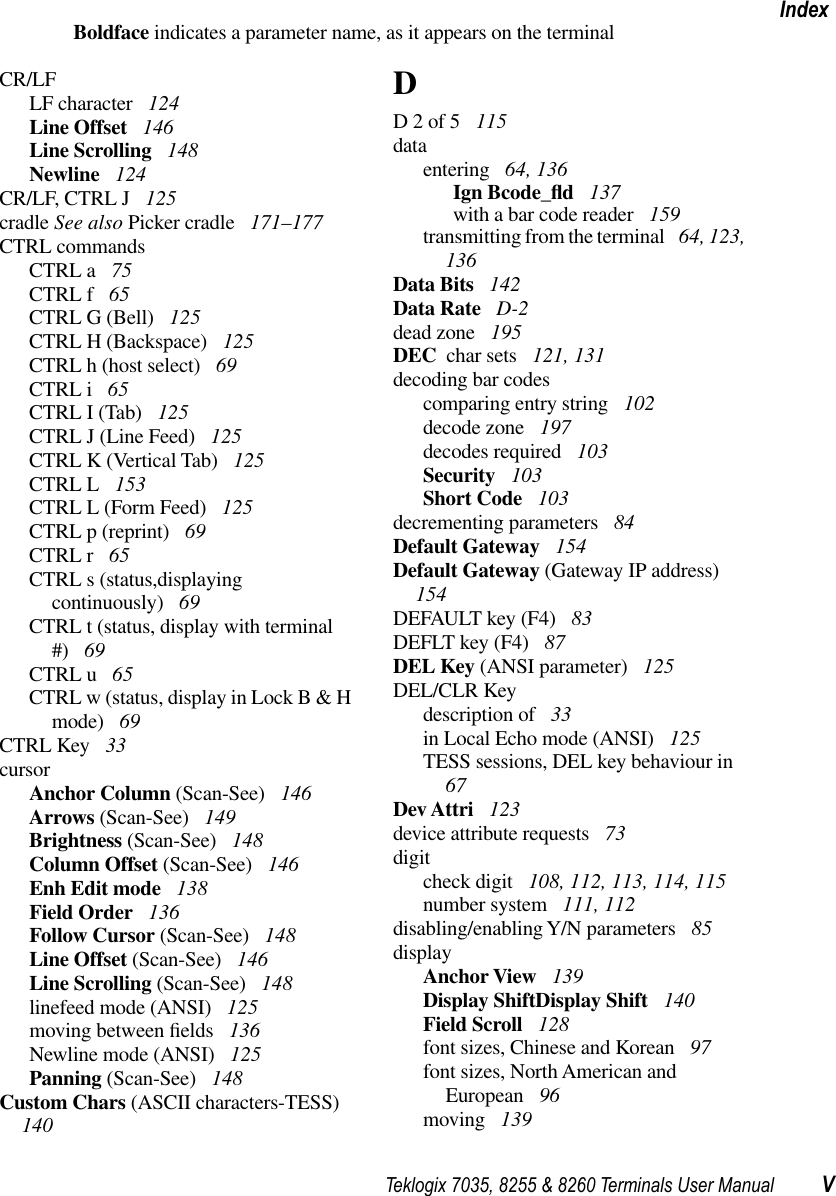
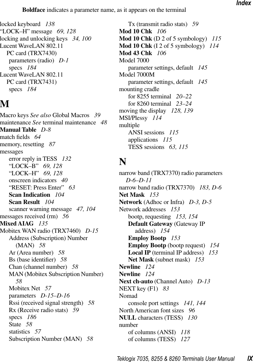
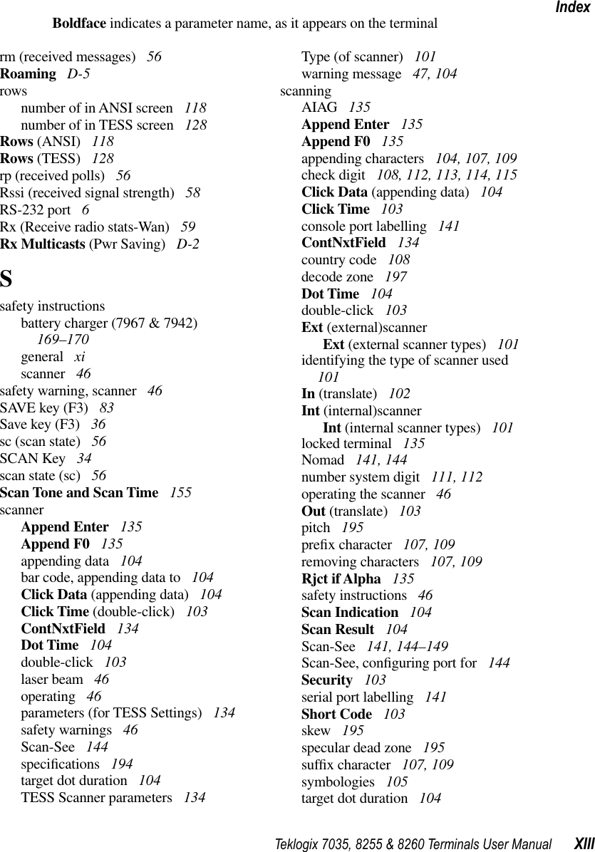
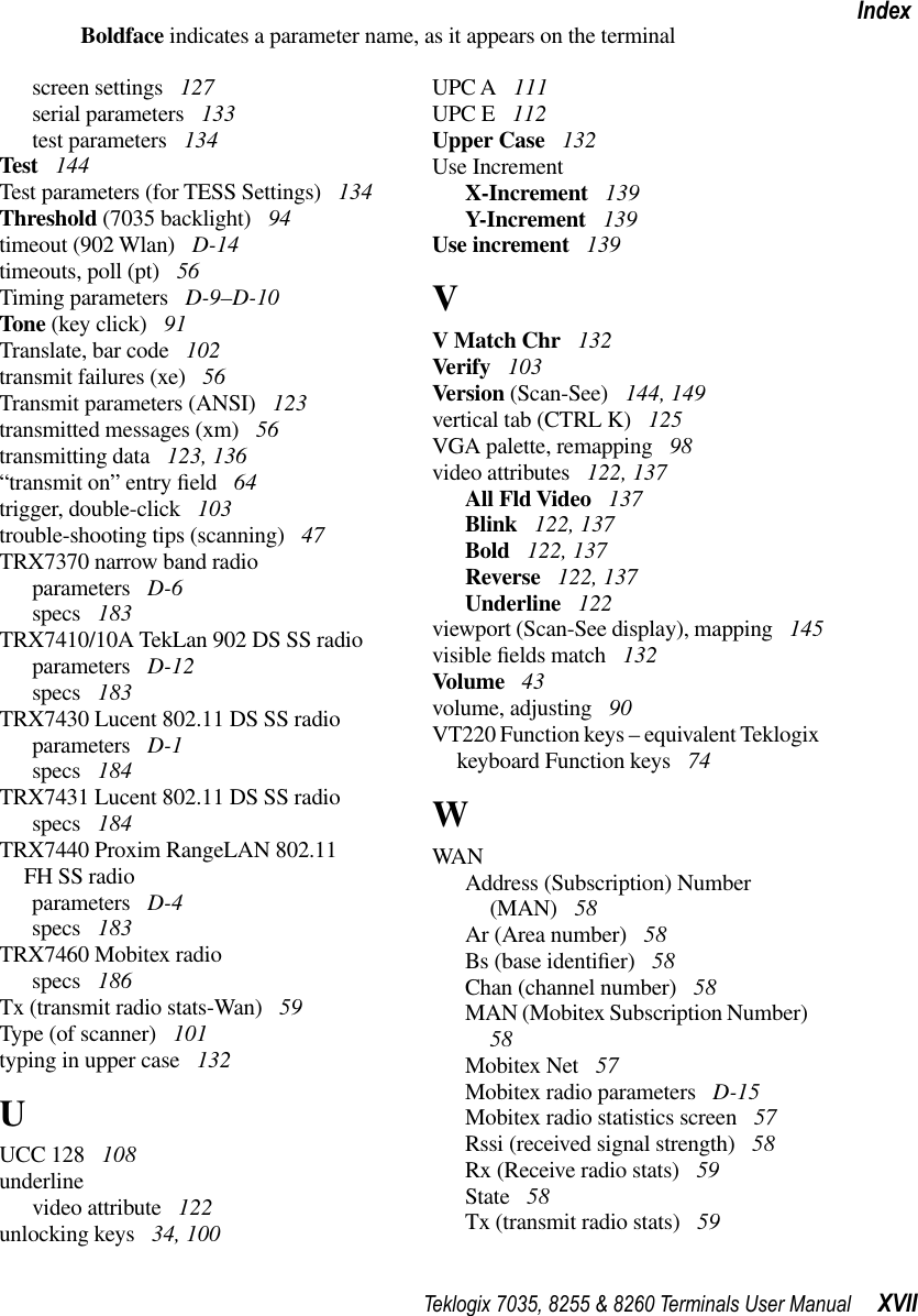
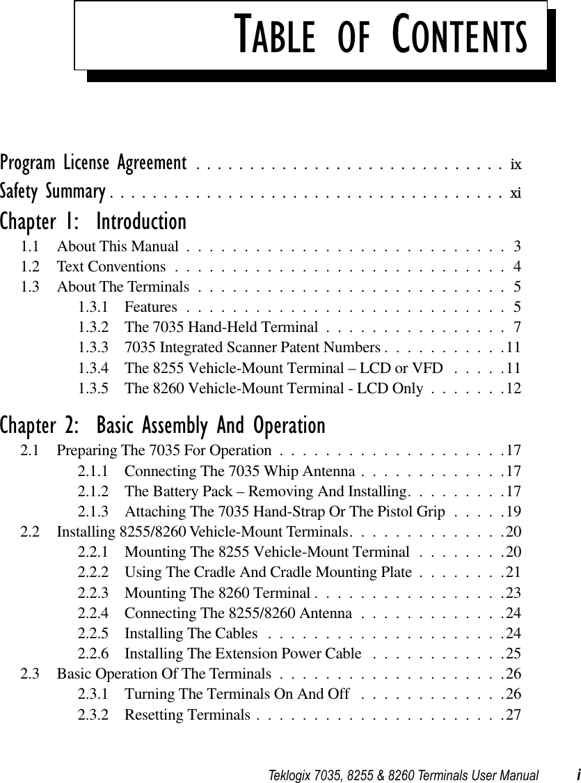
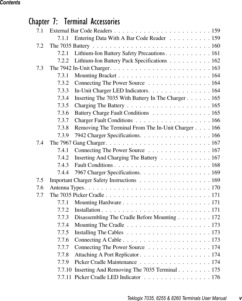
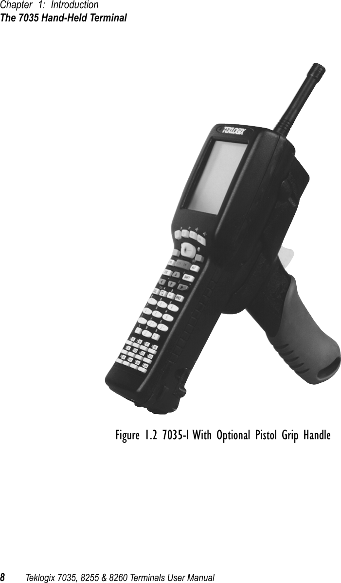
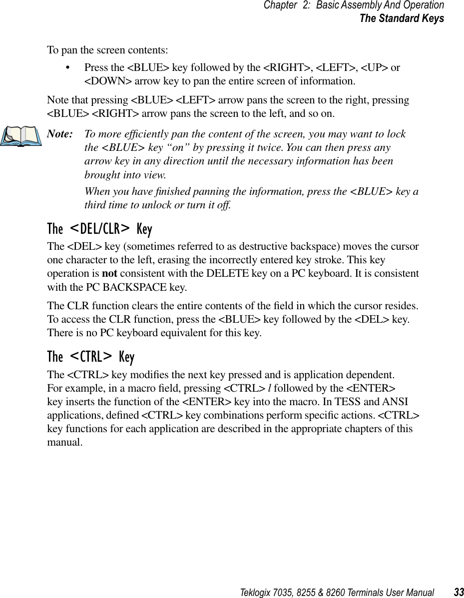
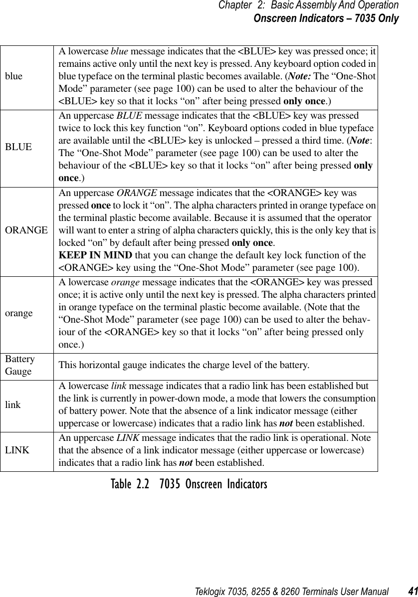
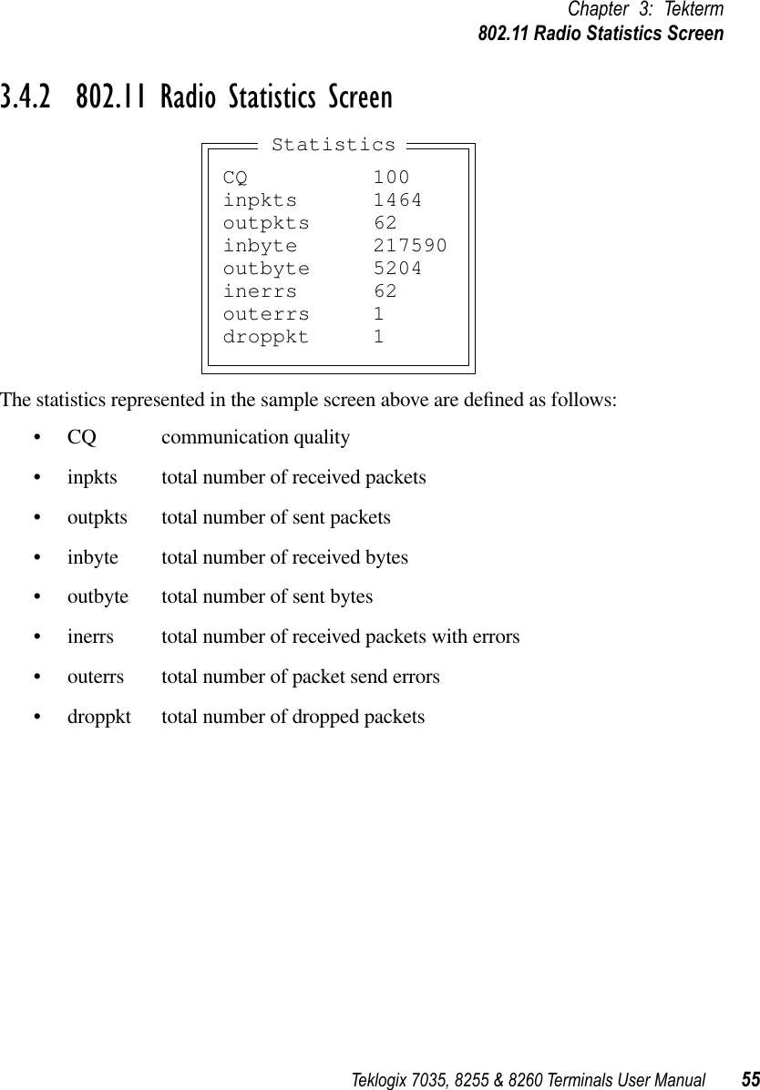
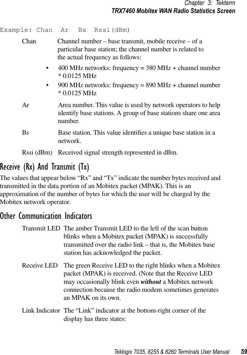
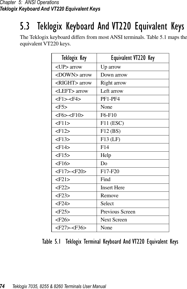
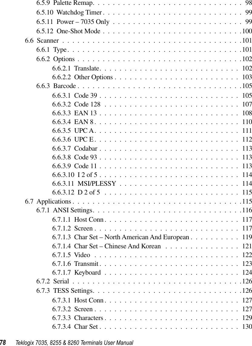
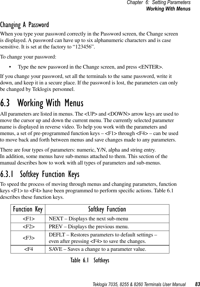
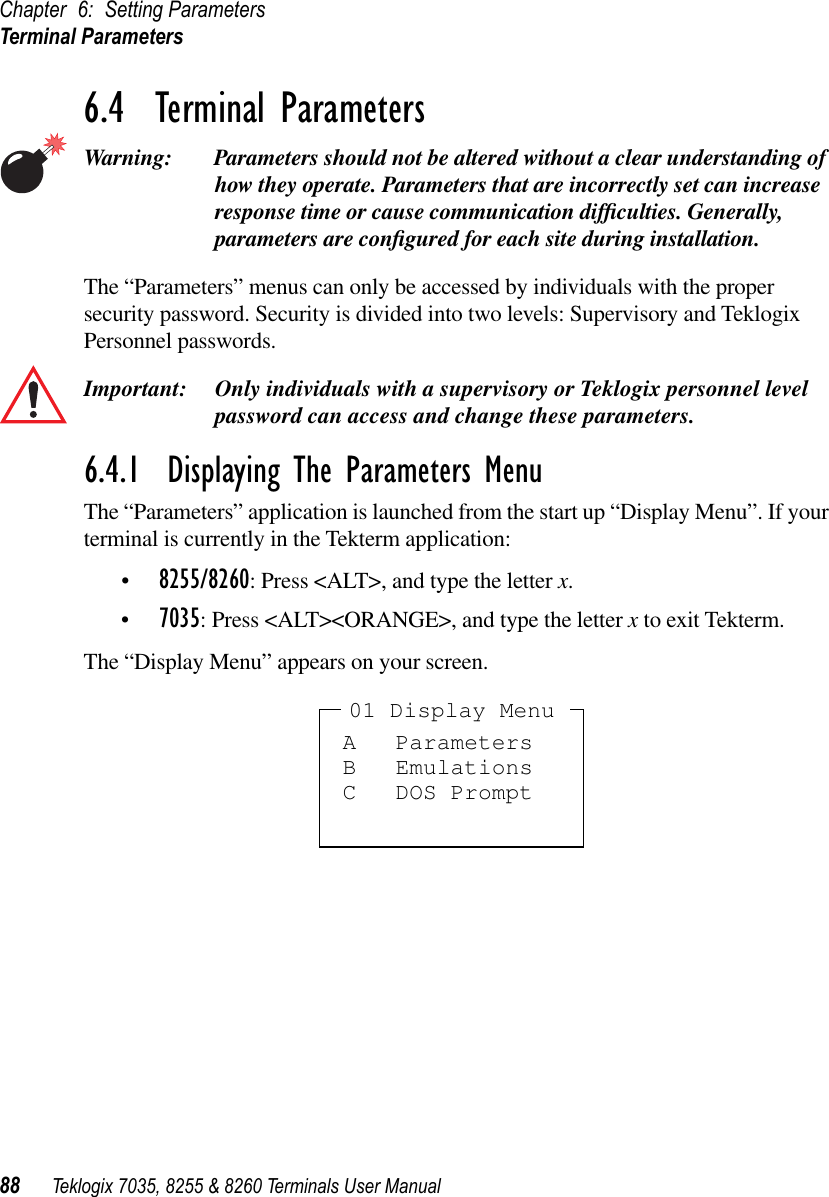
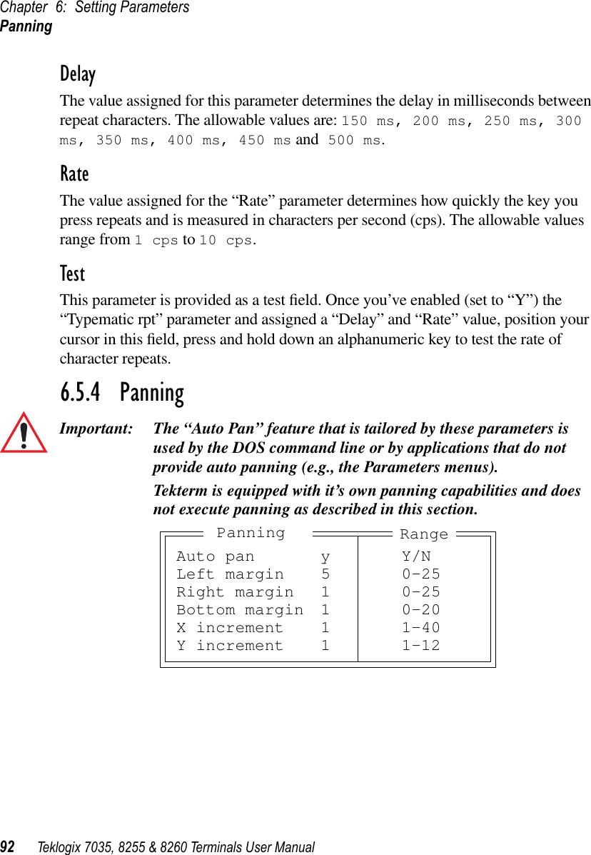
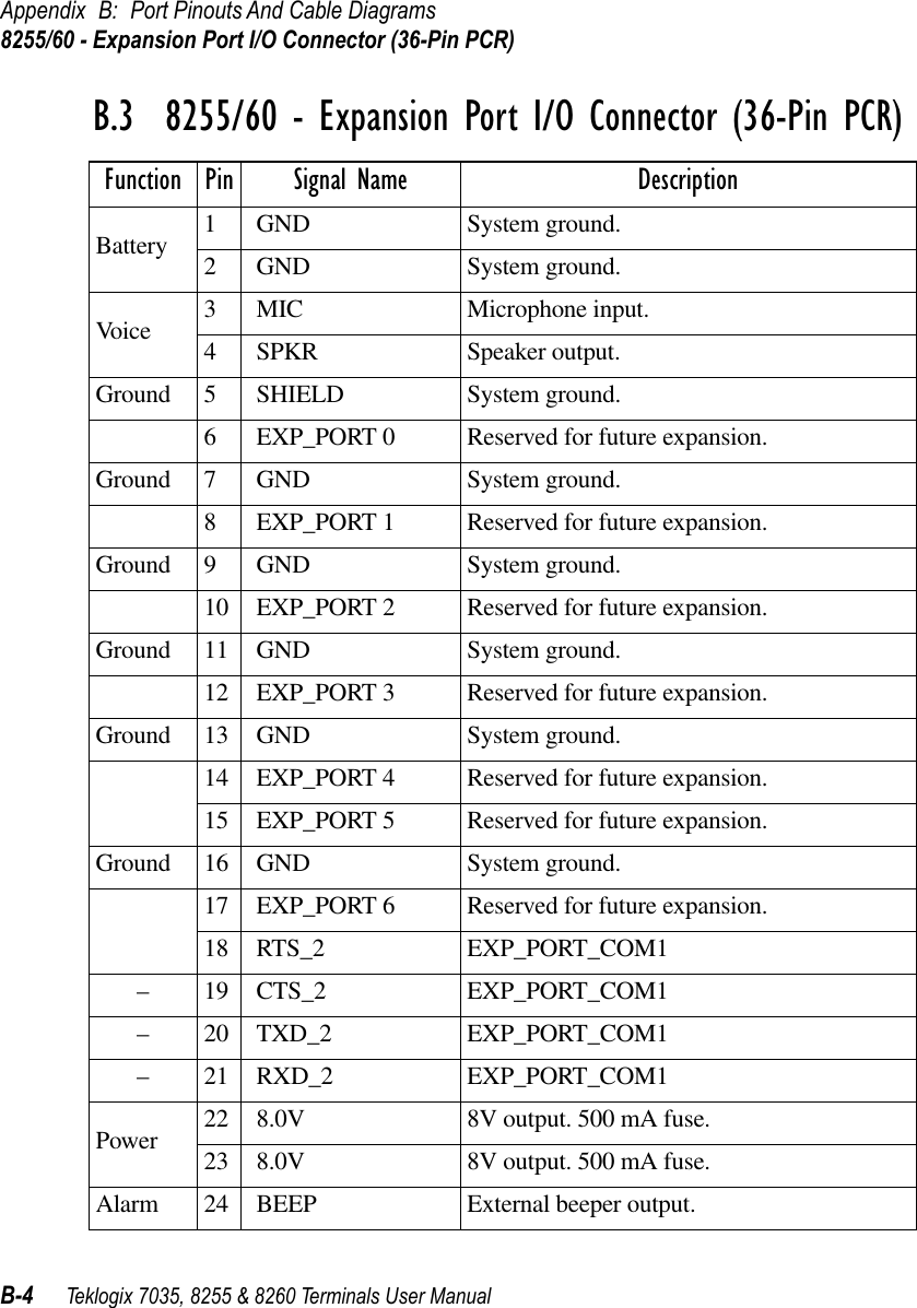
![Chapter 6: Setting ParametersChoosing An ASCII Character152 Teklogix 7035, 8255 & 8260 Terminals User ManualIn macros, the <UP> arrow, <DOWN> arrow, <ENTER> and <DEL> keys have the following functions:•Pressing the <UP> and <DOWN> arrow keys move the cursor between entry fields.•Pressing the <ENTER> key once moves the cursor to the first position in the entry field; pressing <ENTER> a second time completes the entry field, exits the sub-menu and returns the cursor to the “parent” or previous menu.•The <DEL> key deletes the character to the left of the cursor.•The <CLR> key – <BLUE> <DEL> – clears the entire field. If the last character in a field is deleted, the previous contents, if any, reappear.6.10.3 Choosing An ASCII CharacterImportant: Make sure the <CTRL> and <SHIFT> keys are turned off! By pressing either the <RIGHT> or <LEFT> arrow key, you can cycle through a set of printable characters not available on the keyboard. The sample below is a set of ASCII characters not accessible from the keyboard.7035: / < > % ^ & ` ~ | [ ] { } " ' ? = + ;8255/8260: ^ & ‘ ~ | [ ] { } ’ " •Press the <RIGHT> arrow to display the next character in this sequence, and the <LEFT> arrow to display the previous one.6.10.4 Adding Additional ASCII CharactersWhen you’ve chosen an ASCII character and want to add another one in the same field, the cursor must be moved to the right of the existing character. Normally, pressing the <RIGHT> arrow key moves the cursor to the right, but in a string entry field, pressing the <RIGHT> arrow key cycles through the available ASCII characters instead. If you’ve already chosen an ASCII character and want to add another one in the field, you need to take a few extra steps to move the cursor to the right.To add another ASCII character in the string entry field, next to the one you’ve already chosen:•Type a numeric character – for example, type the number 7.•Next, press the <DEL> keyThe cursor is now positioned to the right of the previously selected ASCII character.•Press the <RIGHT> or <LEFT> arrow key to scroll through the ASCII characters, and select another character.](https://usermanual.wiki/Psion/WLPC24H.7035-8255-8260-User-Manual/User-Guide-92261-Page-172.png)

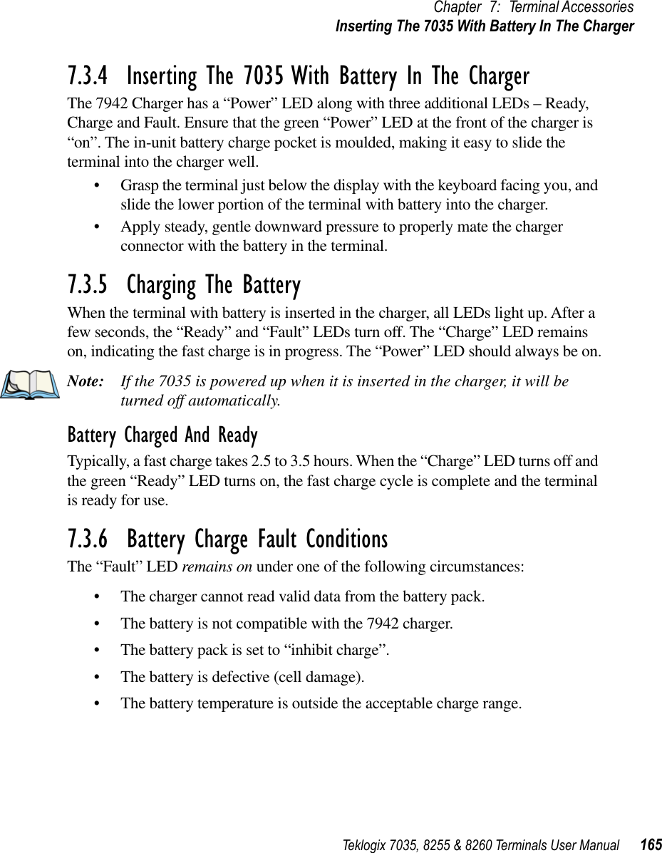
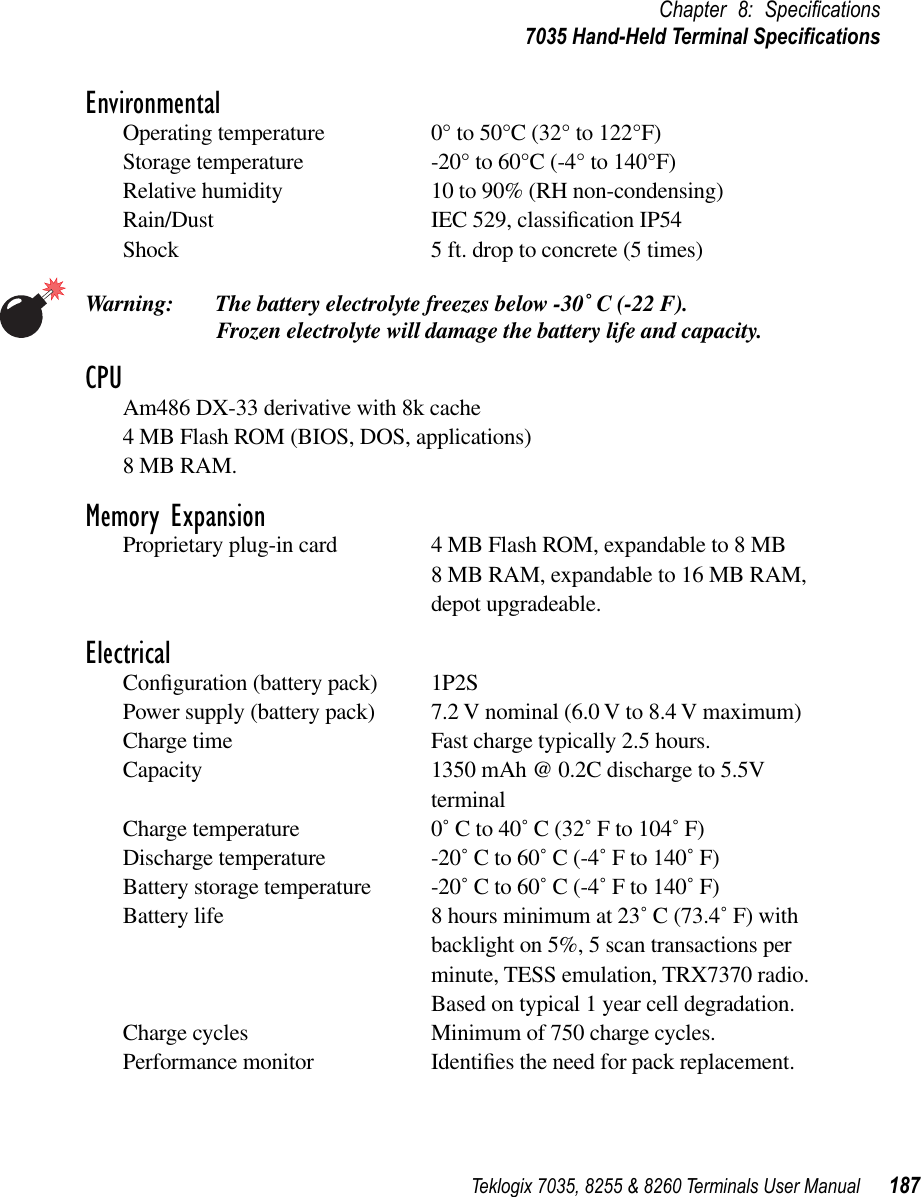
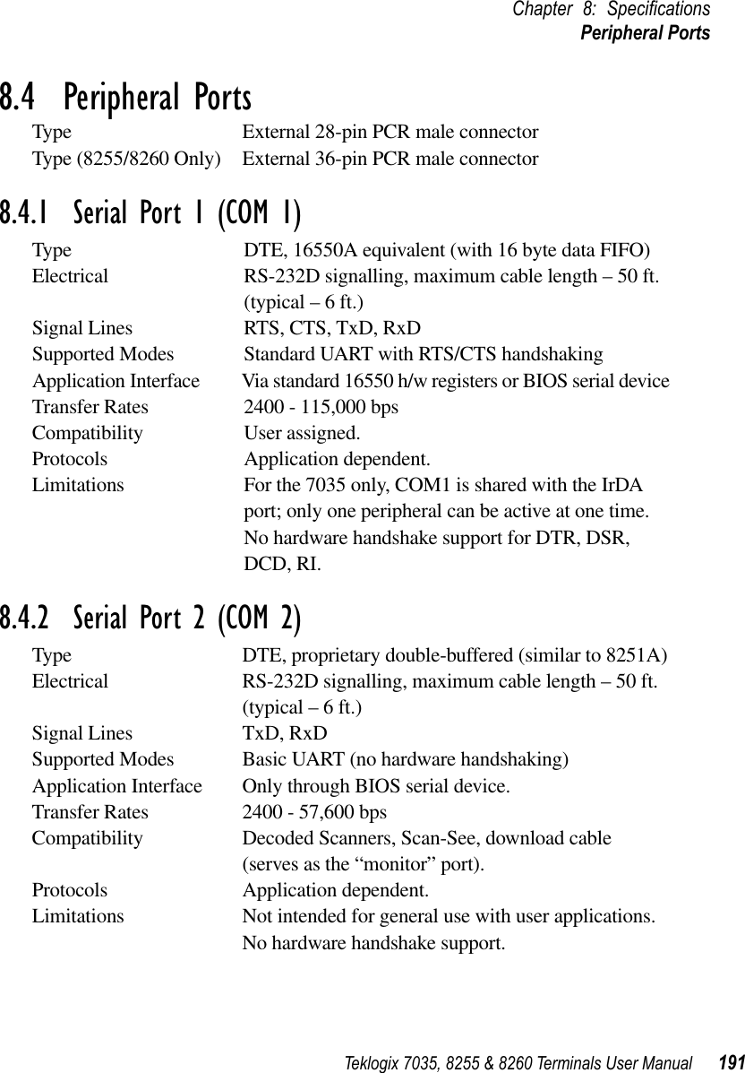

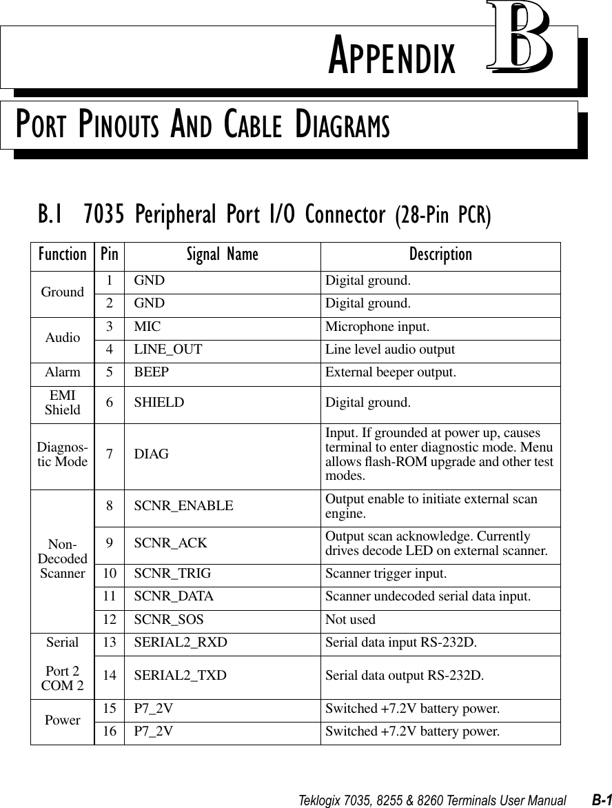
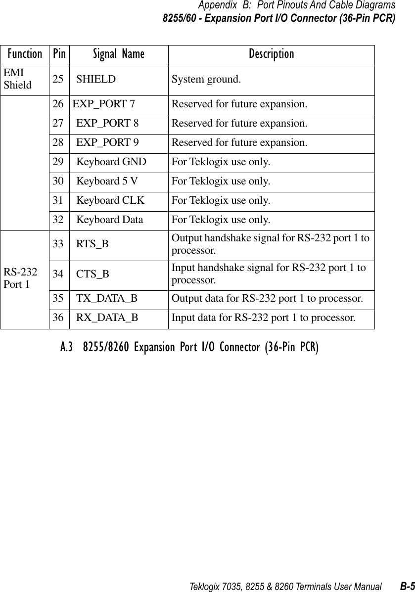
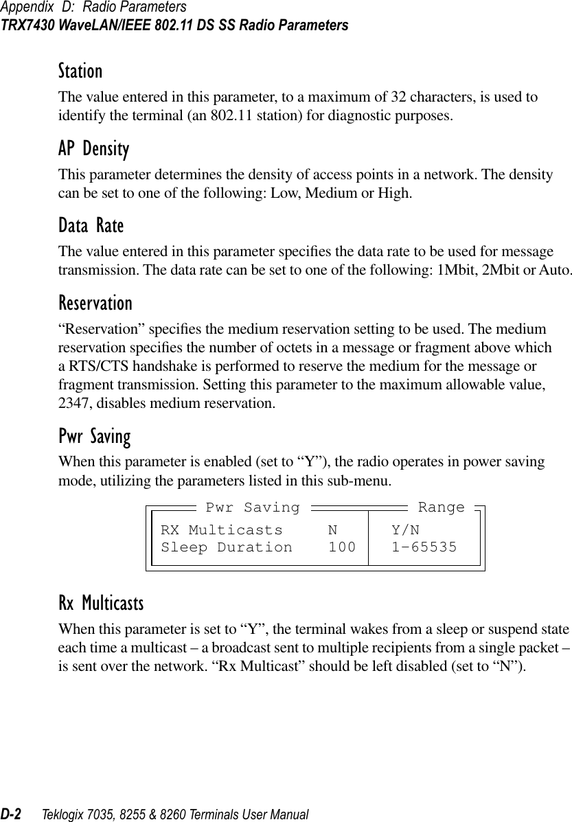
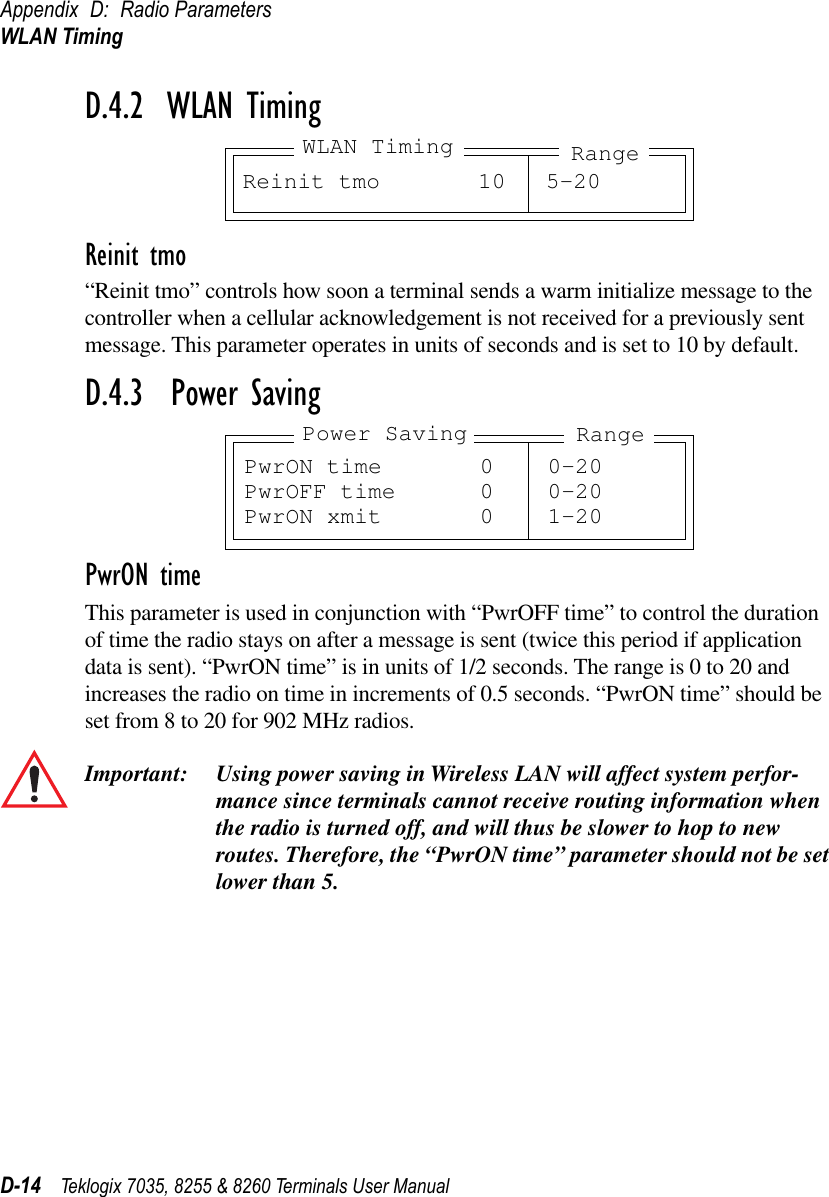
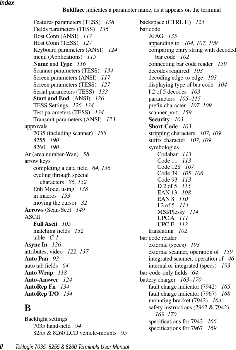
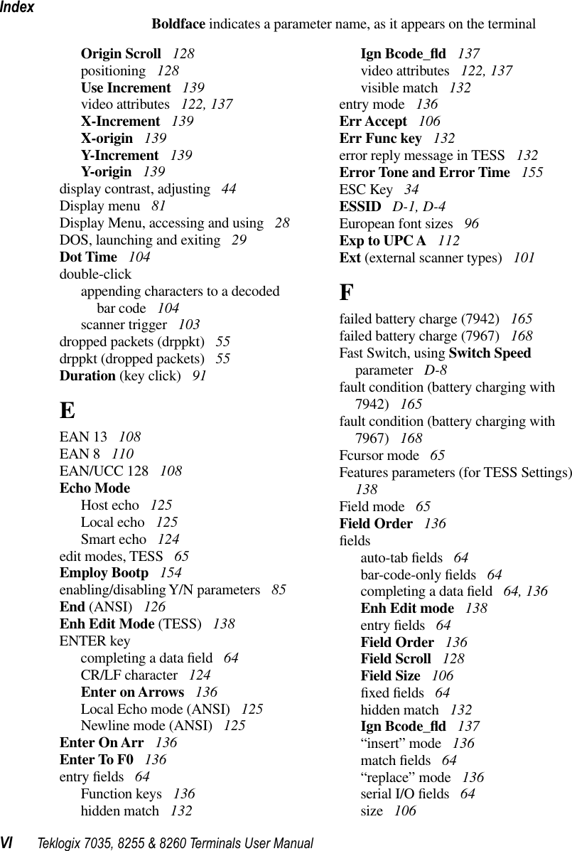
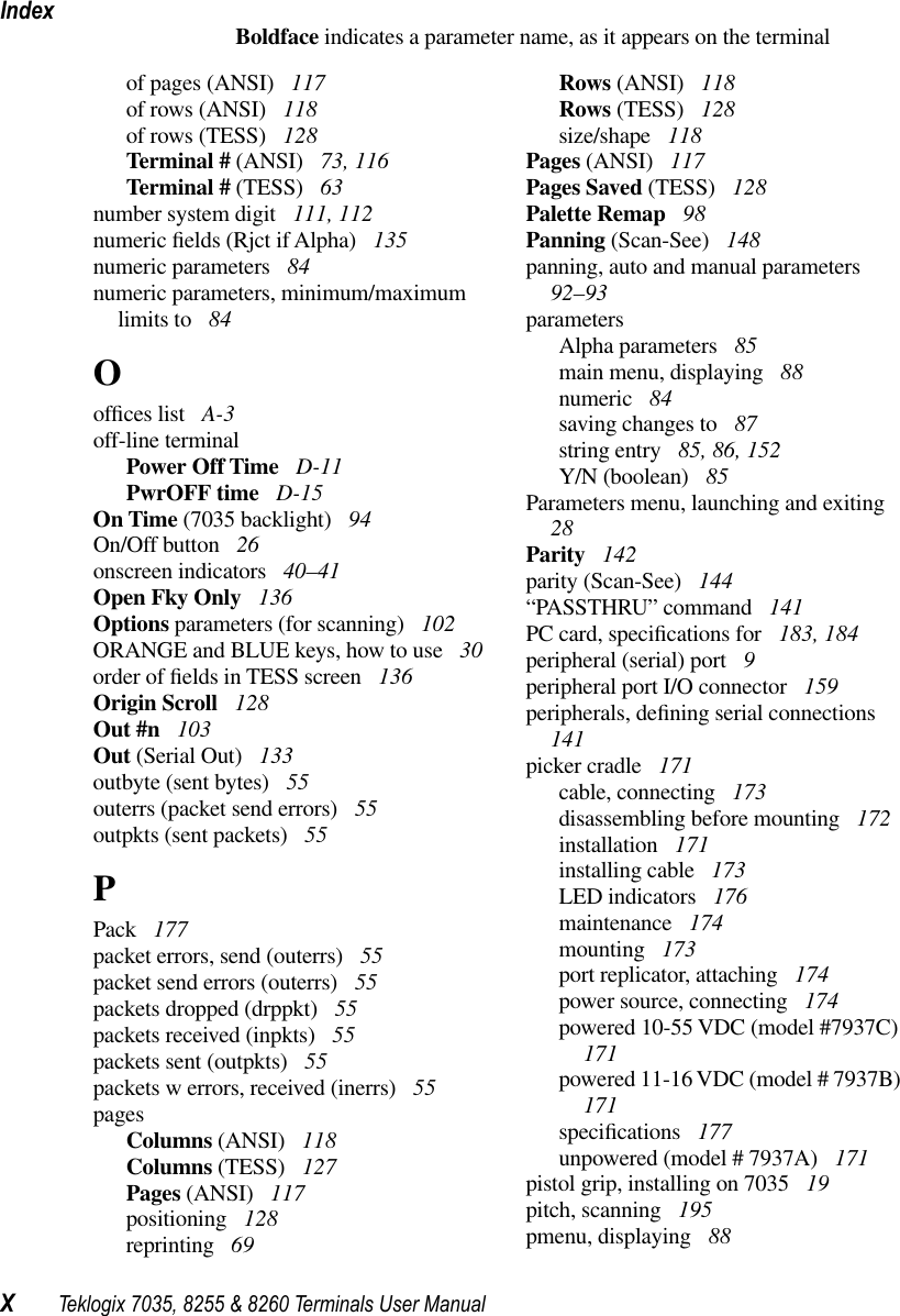
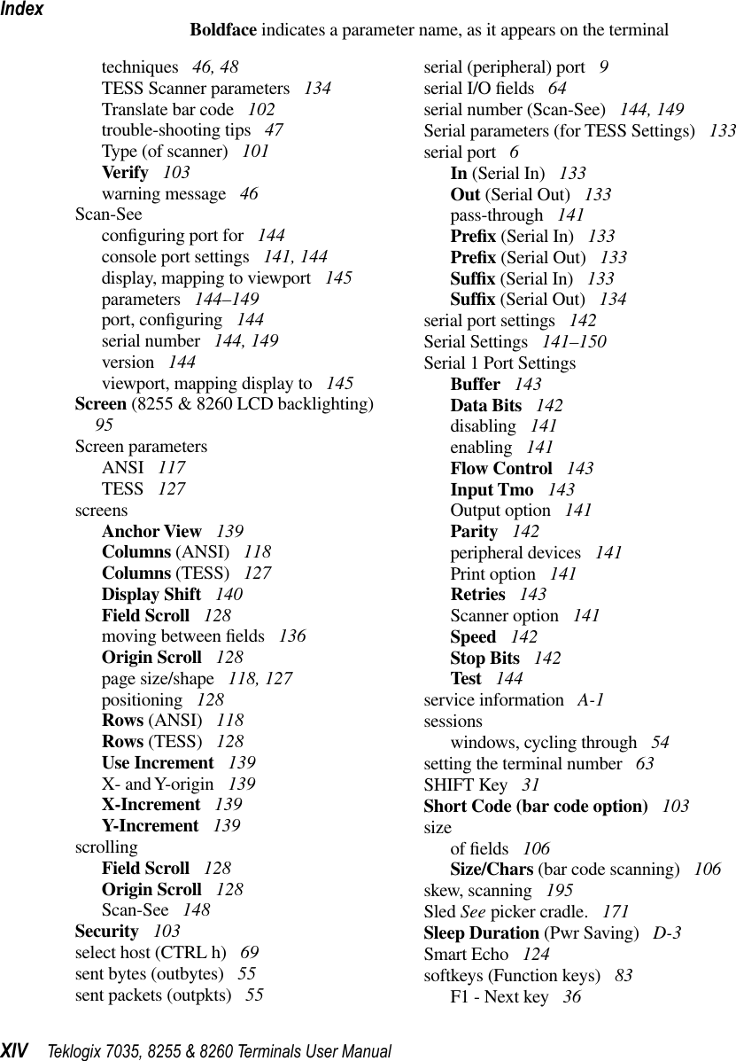
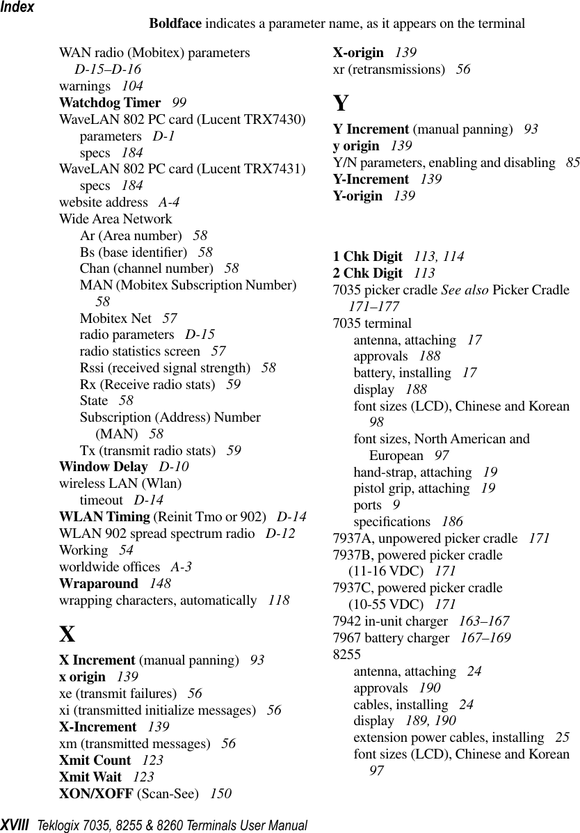
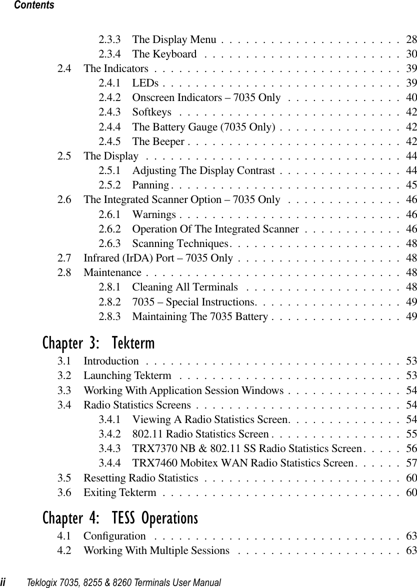
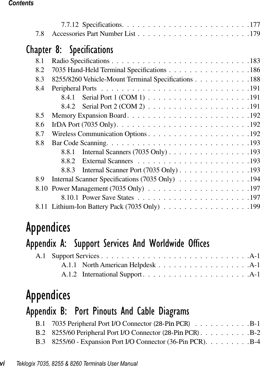
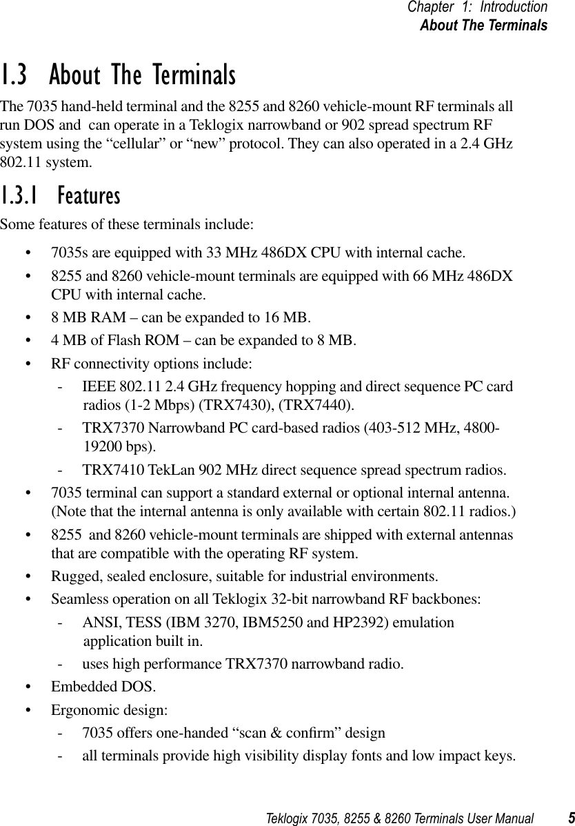
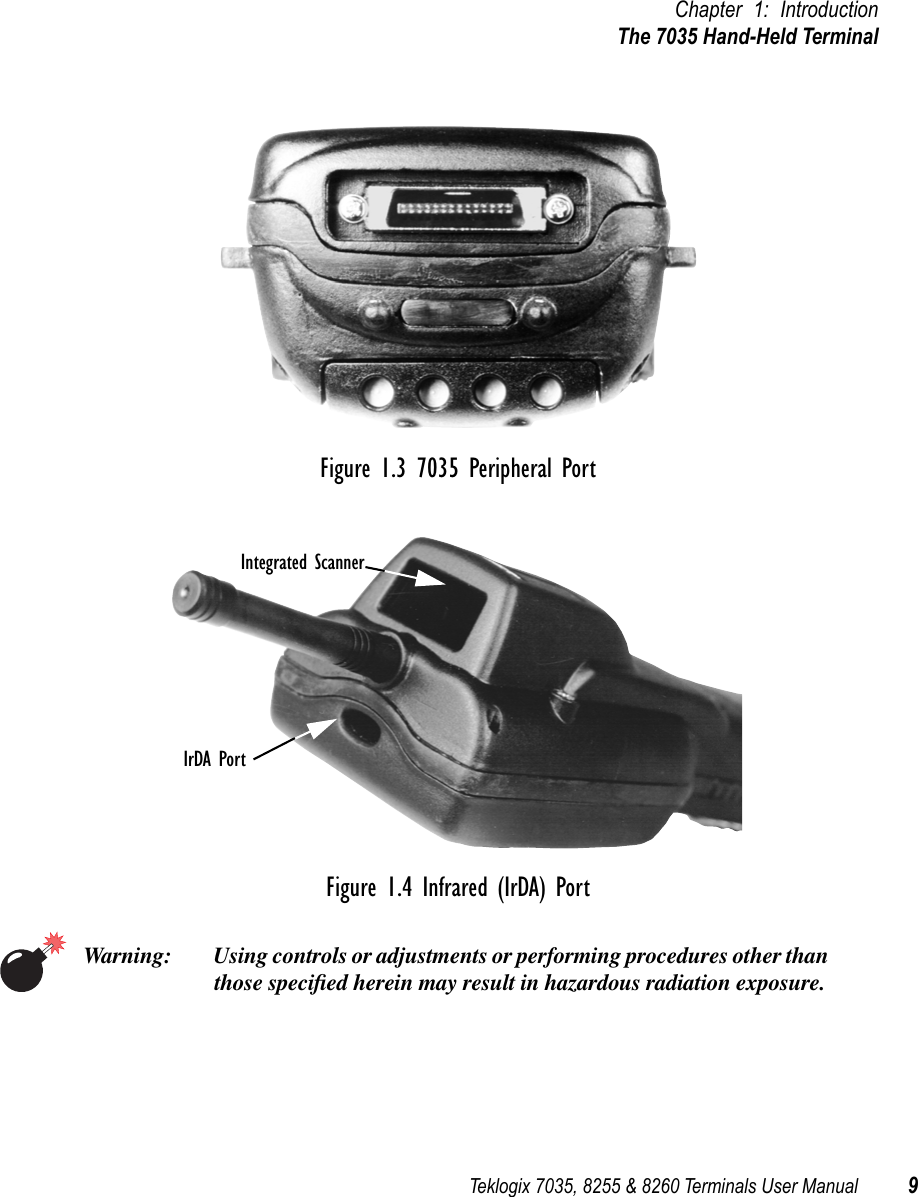
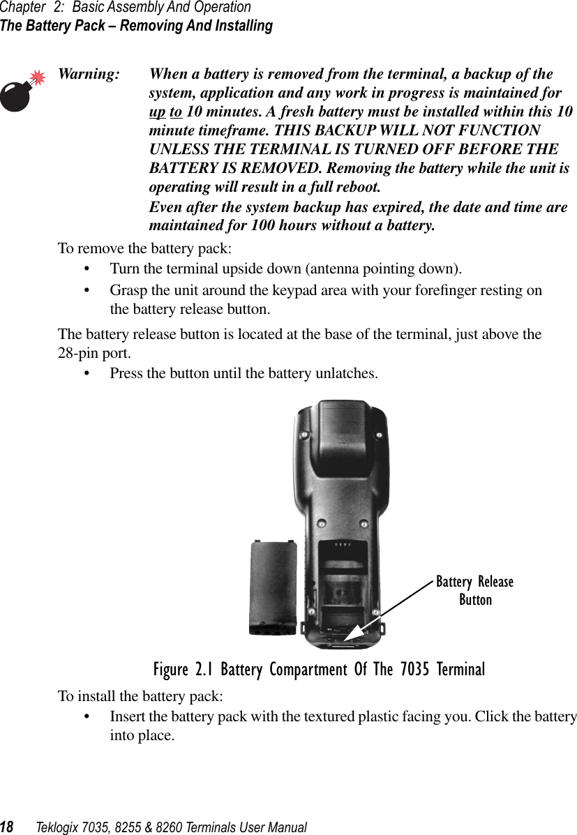
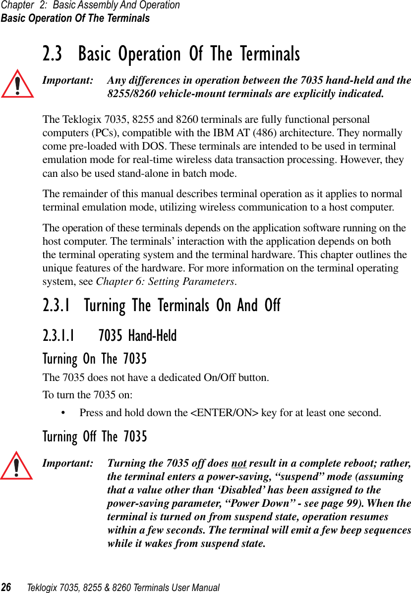
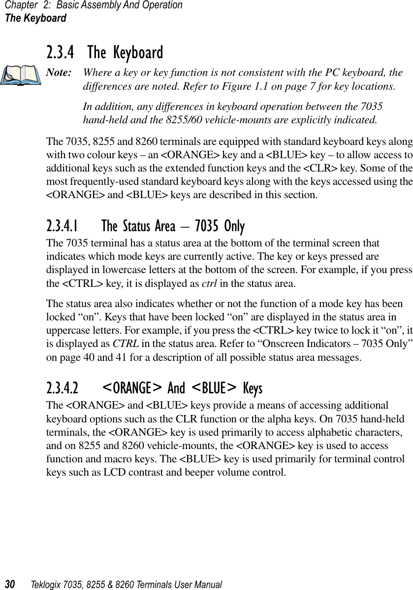
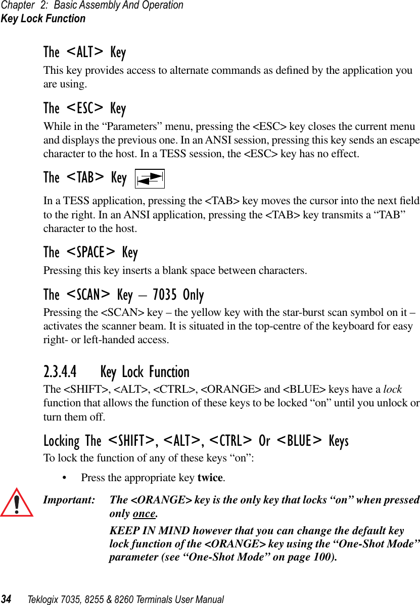
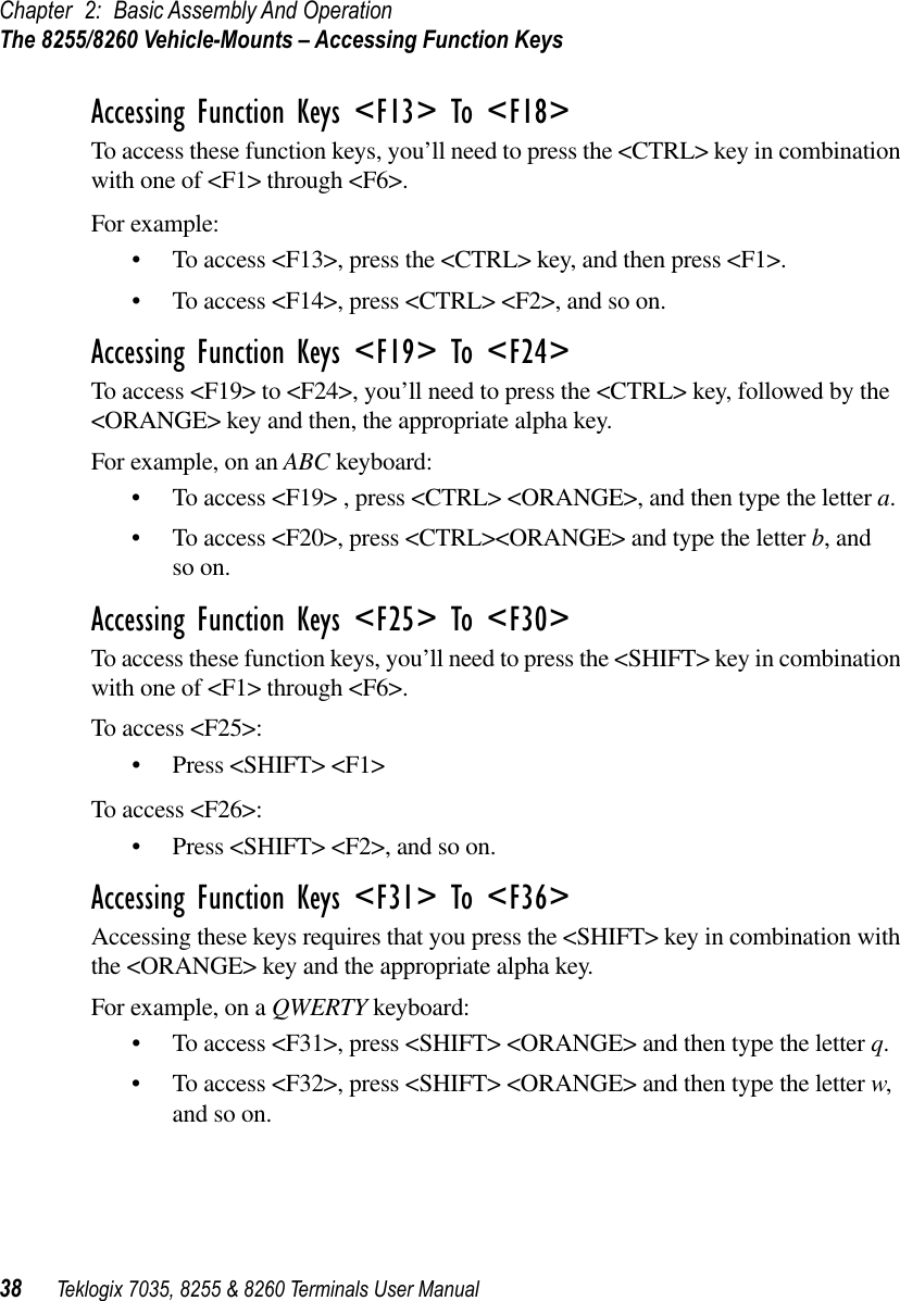
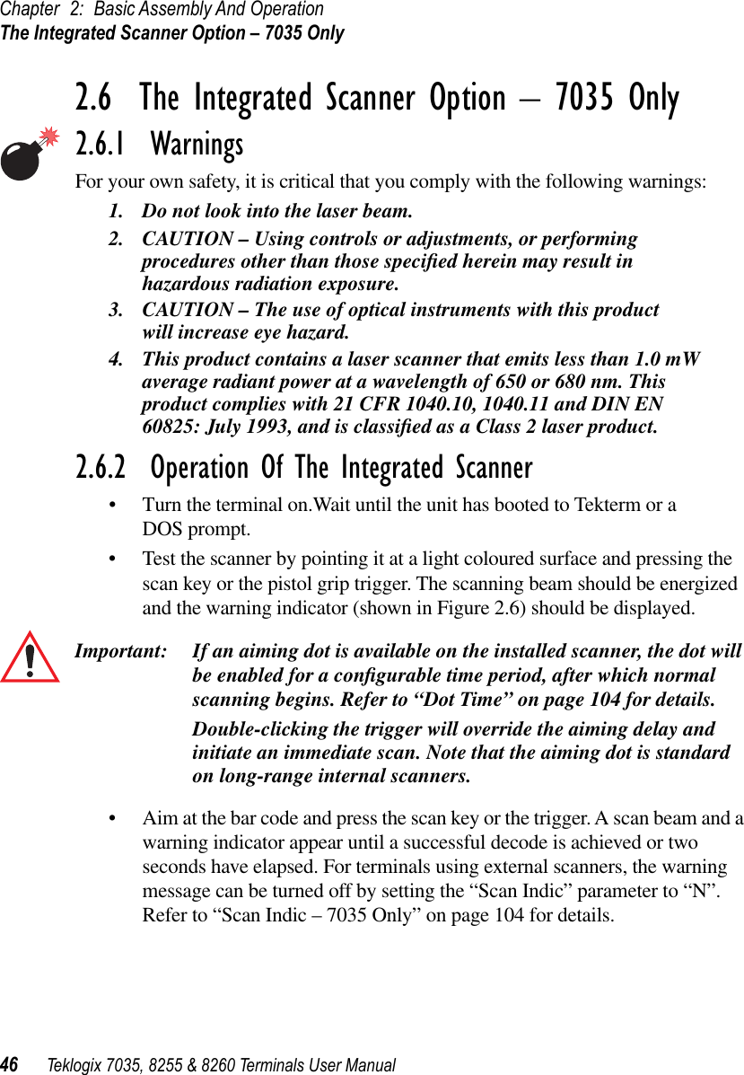
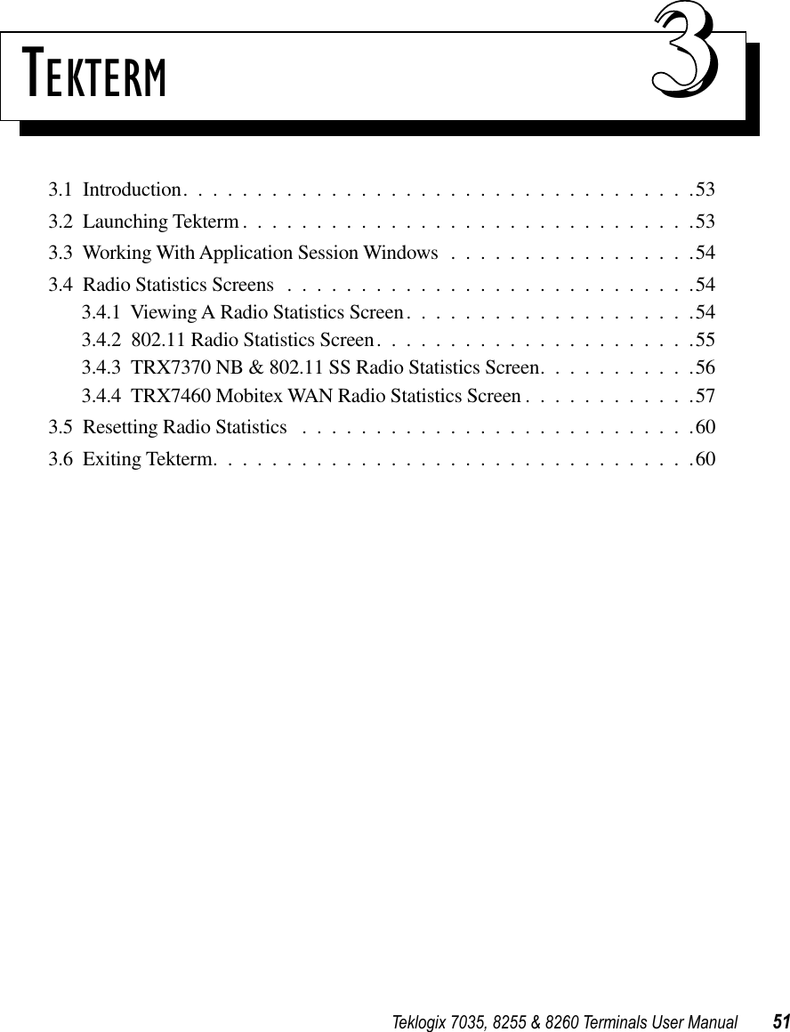
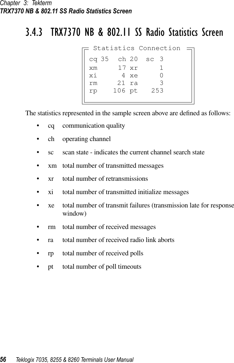
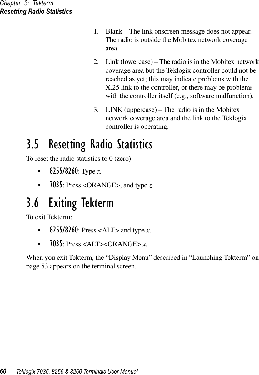
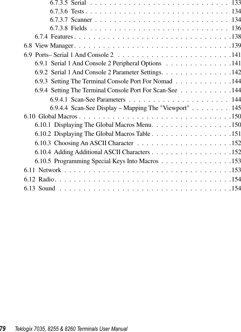
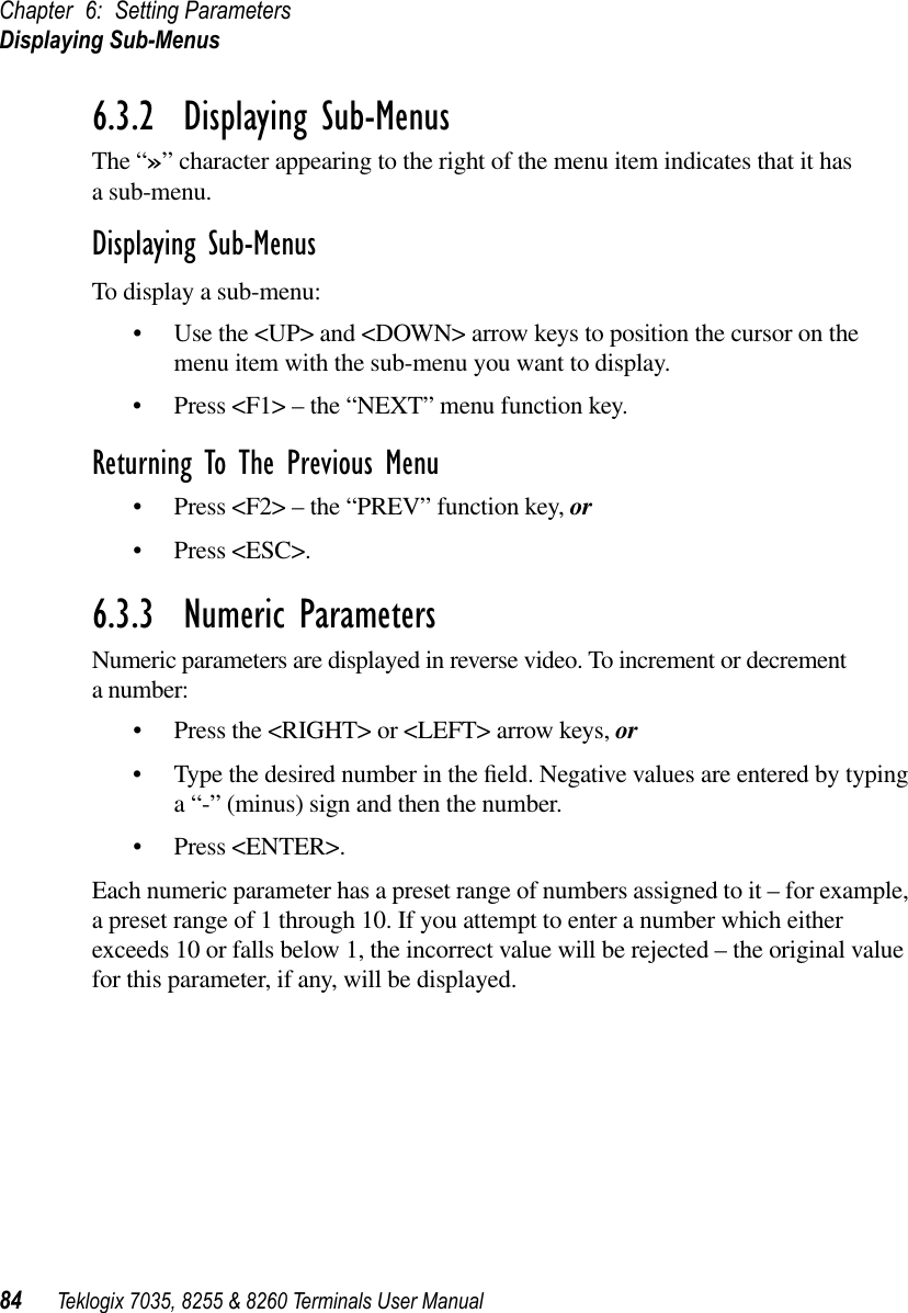
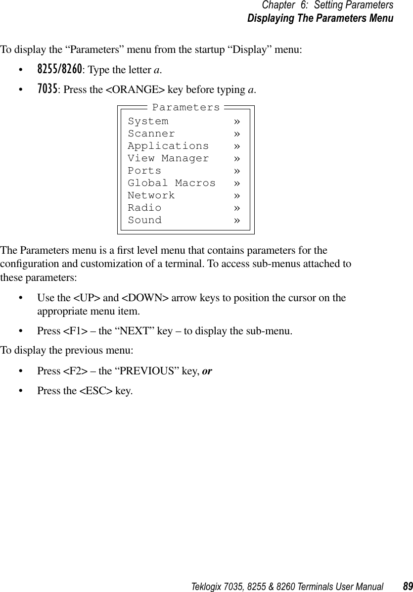
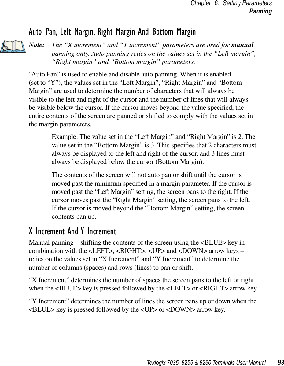
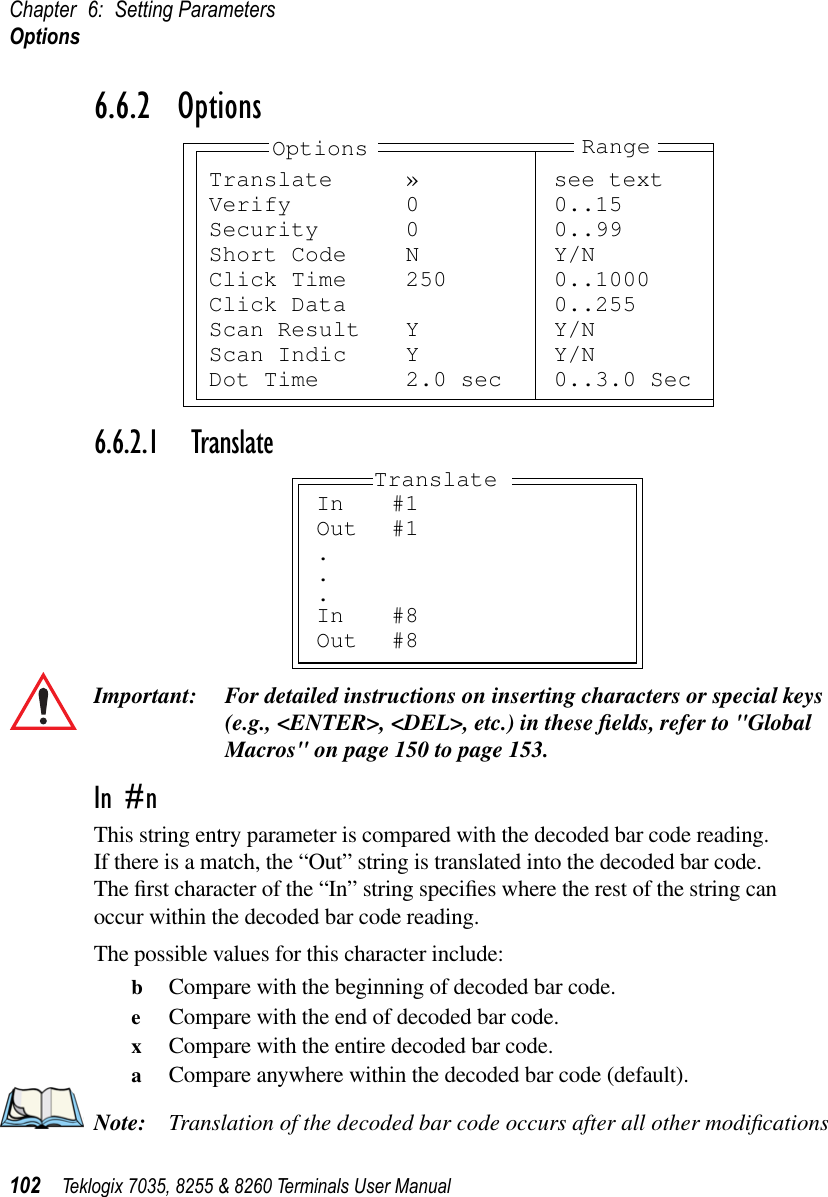
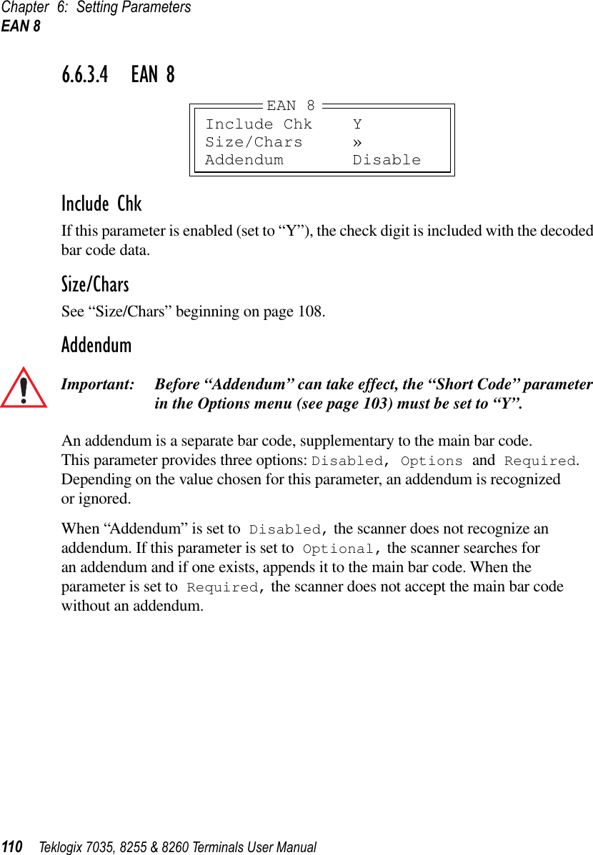
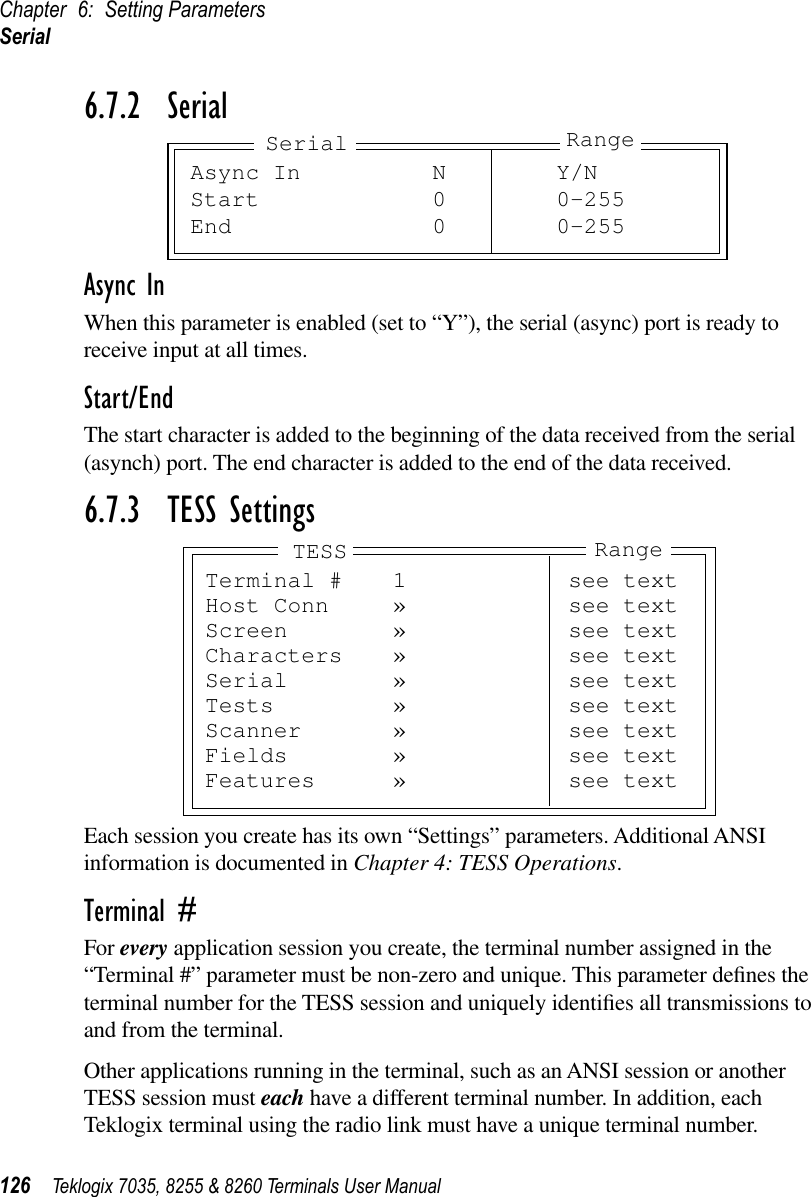
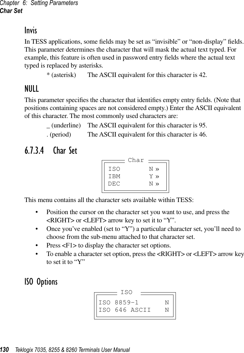
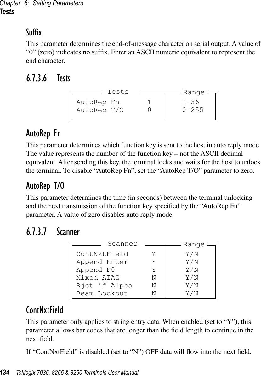
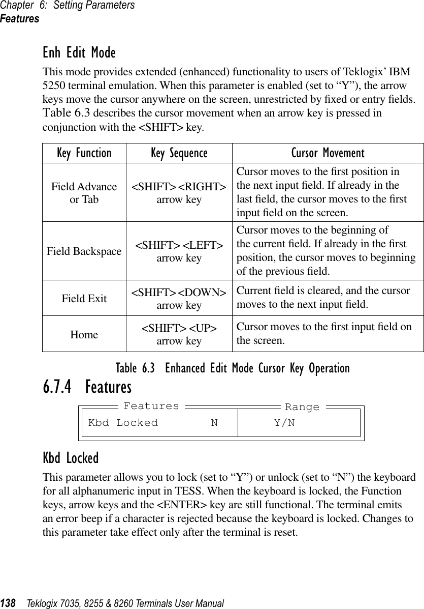
![Appendix C: ASCII Character TableC-2 Teklogix 7035, 8255 & 8260 Terminals User Manual0011 1100 60 < 3C0011 1101 61 = 3D0011 1110 62 > 3E0011 1111 63 ? 3F0101 0000 64 @ 400101 0001 65 A 410101 0010 66 B 420101 0011 67 C 430101 0100 68 D 440101 0101 69 E 450101 0110 70 F 460101 0111 71 G 470101 1000 72 H 480101 1001 73 I 490101 1010 74 J 4A0101 1011 75 K 4B0101 1100 76 L 4C0101 1101 77 M 4D0101 1110 78 N 4E0101 1111 79 O 4F0101 0000 80 P 500101 0001 81 Q 510101 0010 82 R 520101 0011 83 S 530101 0100 84 T 540101 0101 85 U 550101 0110 86 V 560101 0111 87 W 570101 1000 88 X 580101 1001 89 Y 590101 1010 90 Z 5A0101 1011 91 [ 5B0101 1100 92 \ 5C0101 1101 93 ] 5D0101 1110 94 ^ 5E0101 1111 95 _ 5F0110 0000 96 ‘ 600110 0001 97 a 610110 0010 98 b 62BINARY DEC ASCII HEX0110 0011 99 c 630110 0100 100 d 640110 0101 101 e 650110 0110 102 f 660110 0111 103 g 670110 1000 104 h 680110 1001 105 i 690110 1010 106 j 6A0110 1011 107 k 6B0110 1100 108 l 6C0110 1101 109 m 6D0110 1110 110 n 6E0110 1111 111 o 6F0111 0000 112 p 700111 0001 113 q 710111 0010 114 r 720111 0011 115 s 730111 0100 116 t 740111 0101 117 u 750111 0111 118 v 760111 0111 119 w 770111 1000 120 x 780111 1001 121 y 790111 1010 122 z 7A0111 1011 123 { 7B0111 1100 124 | 7C0111 1101 125 } 7D0111 1110 126 ~ 7E0111 1111 127 7F1000 0000 128 Ç 801000 0001 129 ü 811000 0010 130 é 821000 0011 131 â 831000 0100 132 ä 841000 0101 133 à 851000 0110 134 å 861000 0111 135 ç 871000 1000 136 ê 881000 1001 137 ë 89BINARY DEC ASCII HEX](https://usermanual.wiki/Psion/WLPC24H.7035-8255-8260-User-Manual/User-Guide-92261-Page-234.png)