Contents
- 1. TRX7431 User Manual
- 2. Teklogix 9150 Wireless Gateway User Manual
- 3. Teklogix 9150 Wireless Gateway User Manual Declaration of Conformity
- 4. Teklogix 9150 Wireless Gateway User Manual Cautions to Users
- 5. Teklogix 9150 Wireless Gateway User Manual Teklogix Offices
- 6. Teklogix 9150 Wireless Gateway User Manual Table of Contents
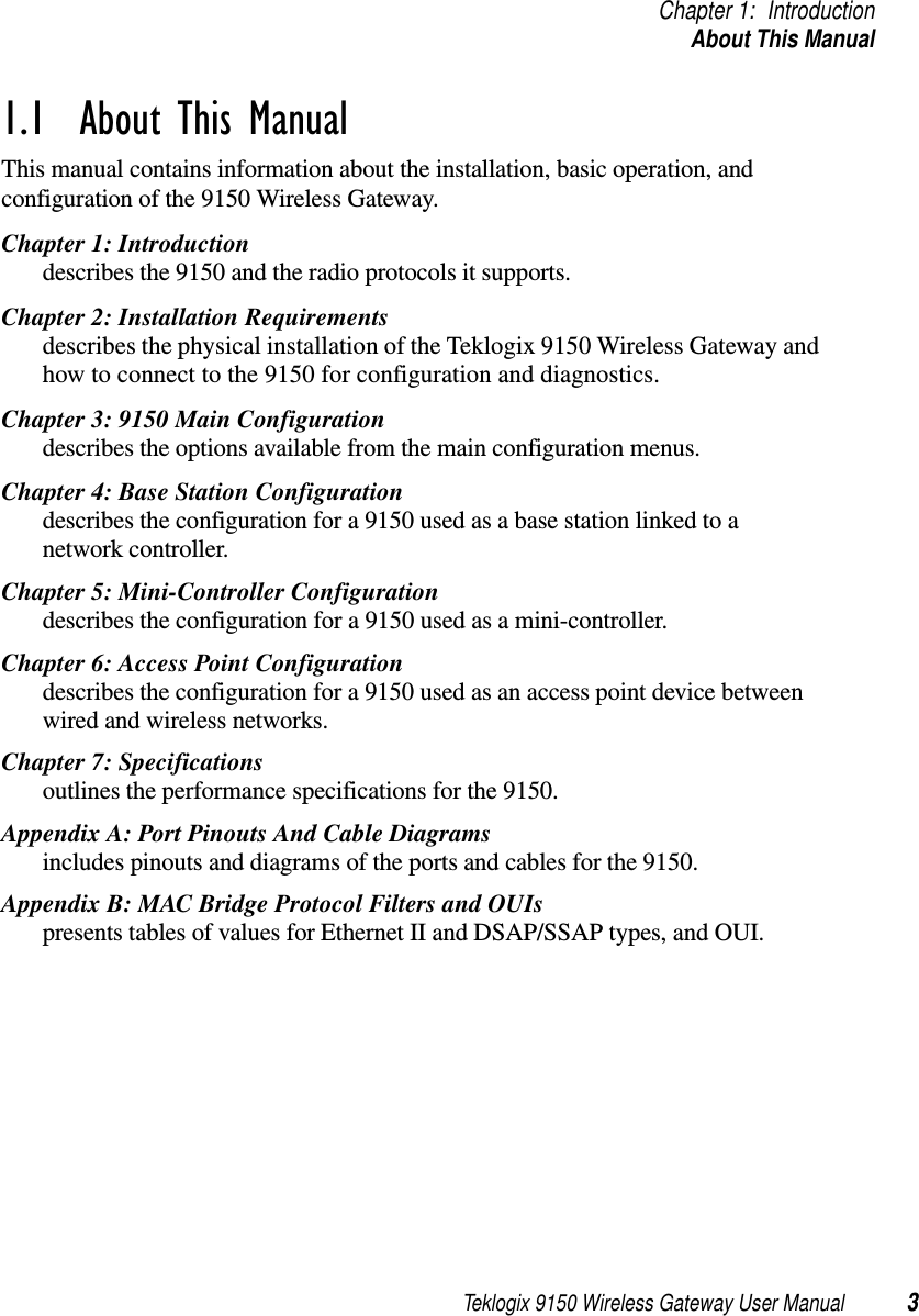
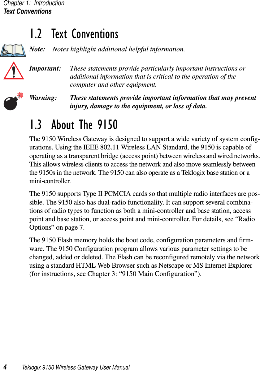
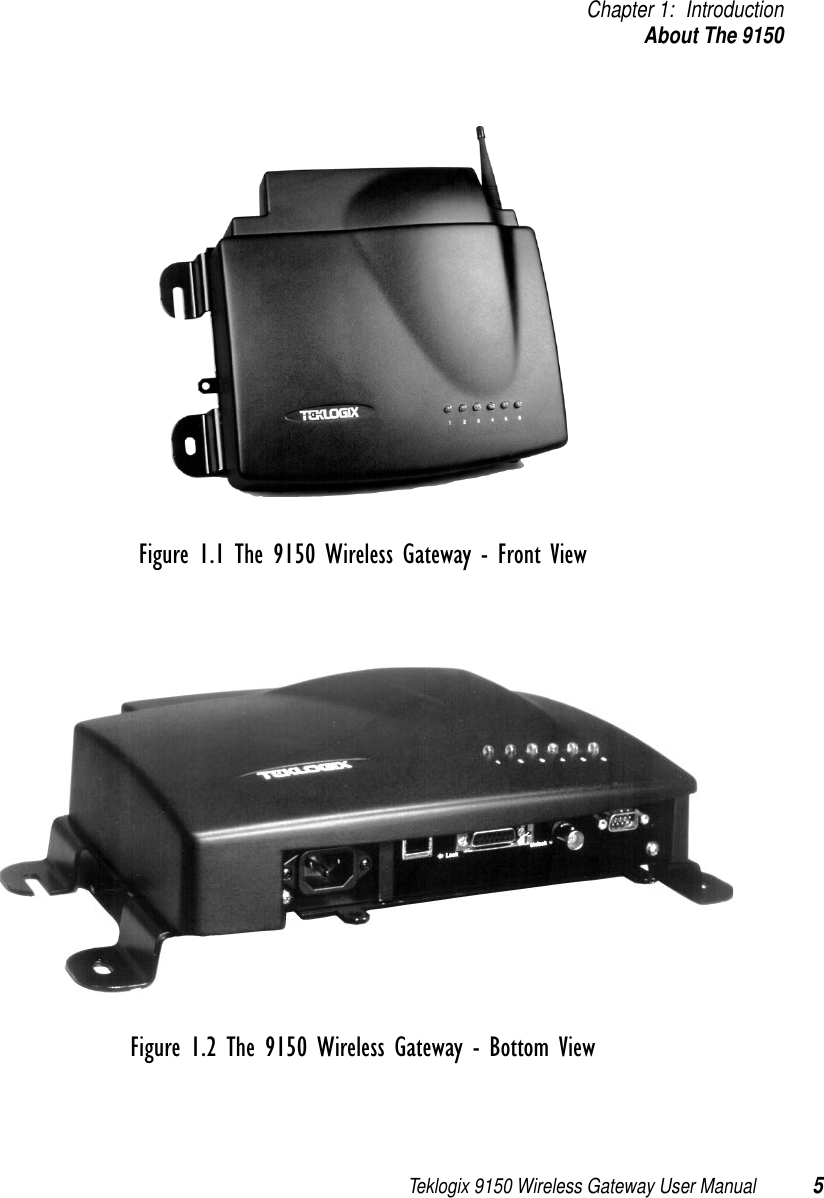
- 7. Teklogix 9150 Wireless Gateway User Manual Chapter 1 Introduction
- 8. Teklogix 9150 Wireless Gateway User Manual Chapter 2 Installation Requirements
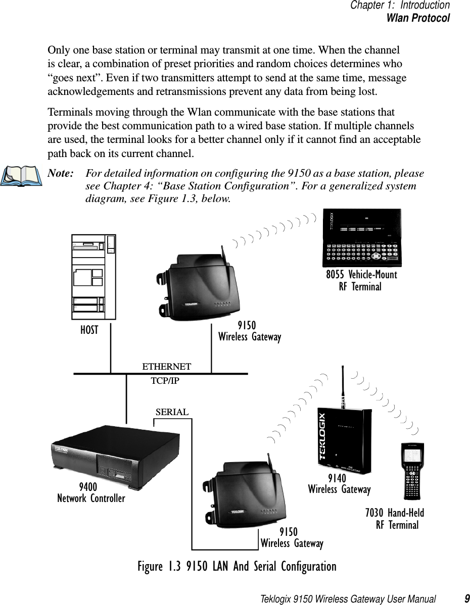
- 9. Teklogix 9150 Wireless Gateway User Manual Chapter 3 9150 Main Configuration
- 10. Teklogix 9150 Wireless Gateway User Manual Chapter 4 Base Station Configuration
- 11. Teklogix 9150 Wireless Gateway User Manual Chapter 5 Mini Controller Configurati
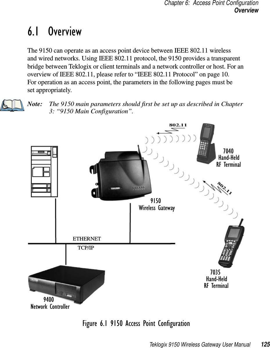
- 12. Teklogix 9150 Wireless Gateway User Manual Chapter 6 Access Point Configuration
- 13. Teklogix 9150 Wireless Gateway User Manual Chapter 7 Specifications
- 14. Teklogix 9150 Wireless Gateway User Manual Appendix A
- 15. Teklogix 9150 Wireless Gateway User Manual Appendix B
- 16. Teklogix 9150 Wireless Gateway User Manual Index
- 17. Teklogix 9150 Wireless Gateway User Manual Appendix A
- 18. 7035 8255 8260 User Manual
- 19. 9150 User Manual
- 20. response to FCC correspondence 15472
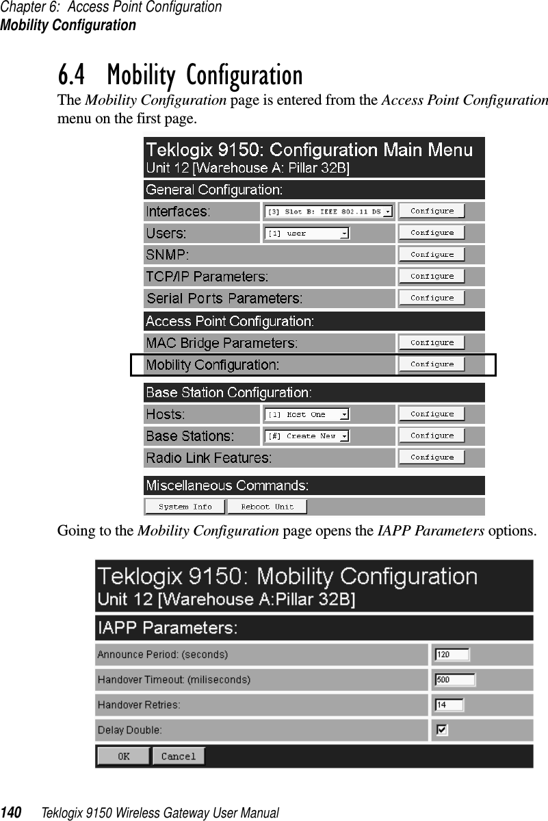
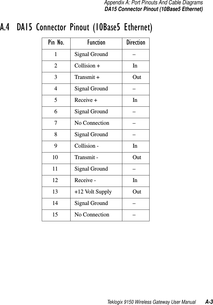
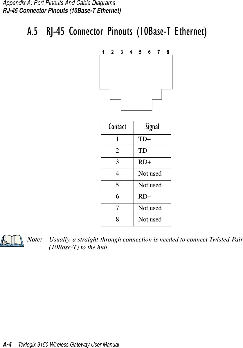
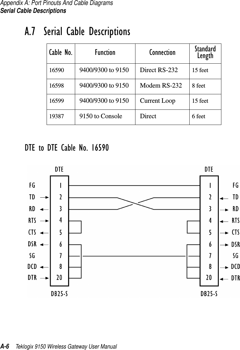
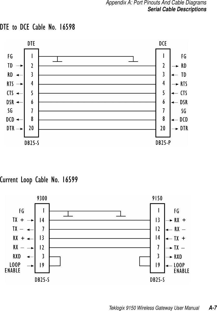
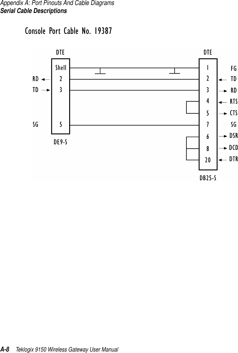
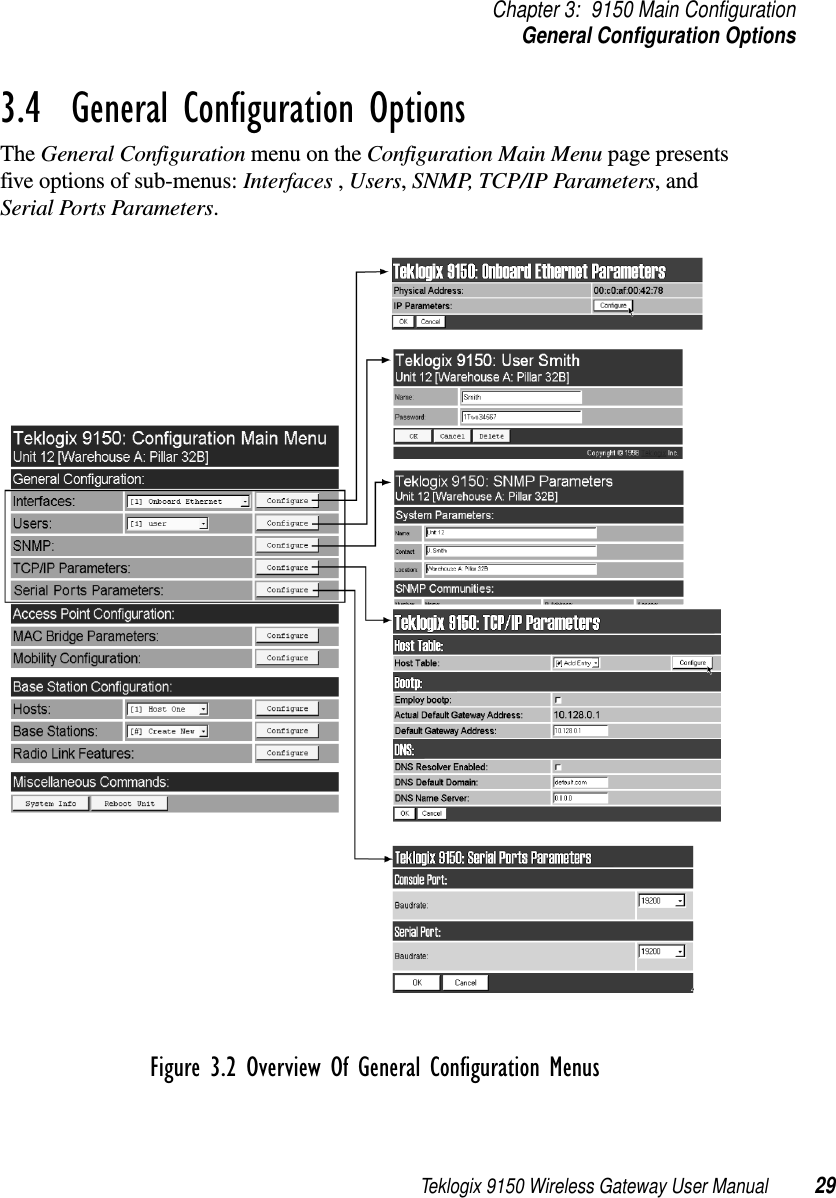
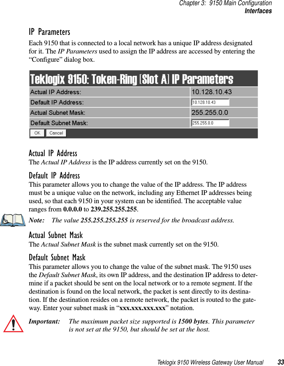
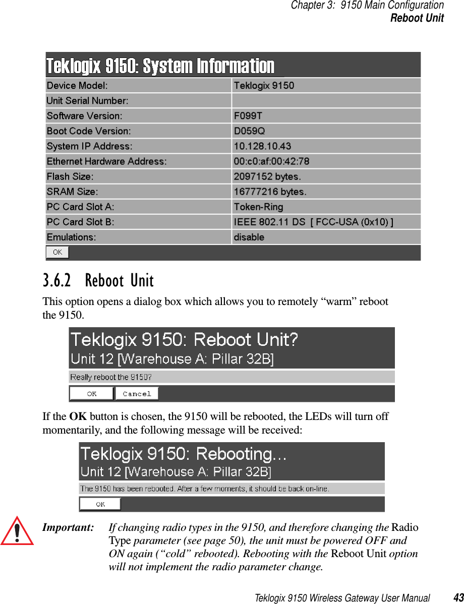
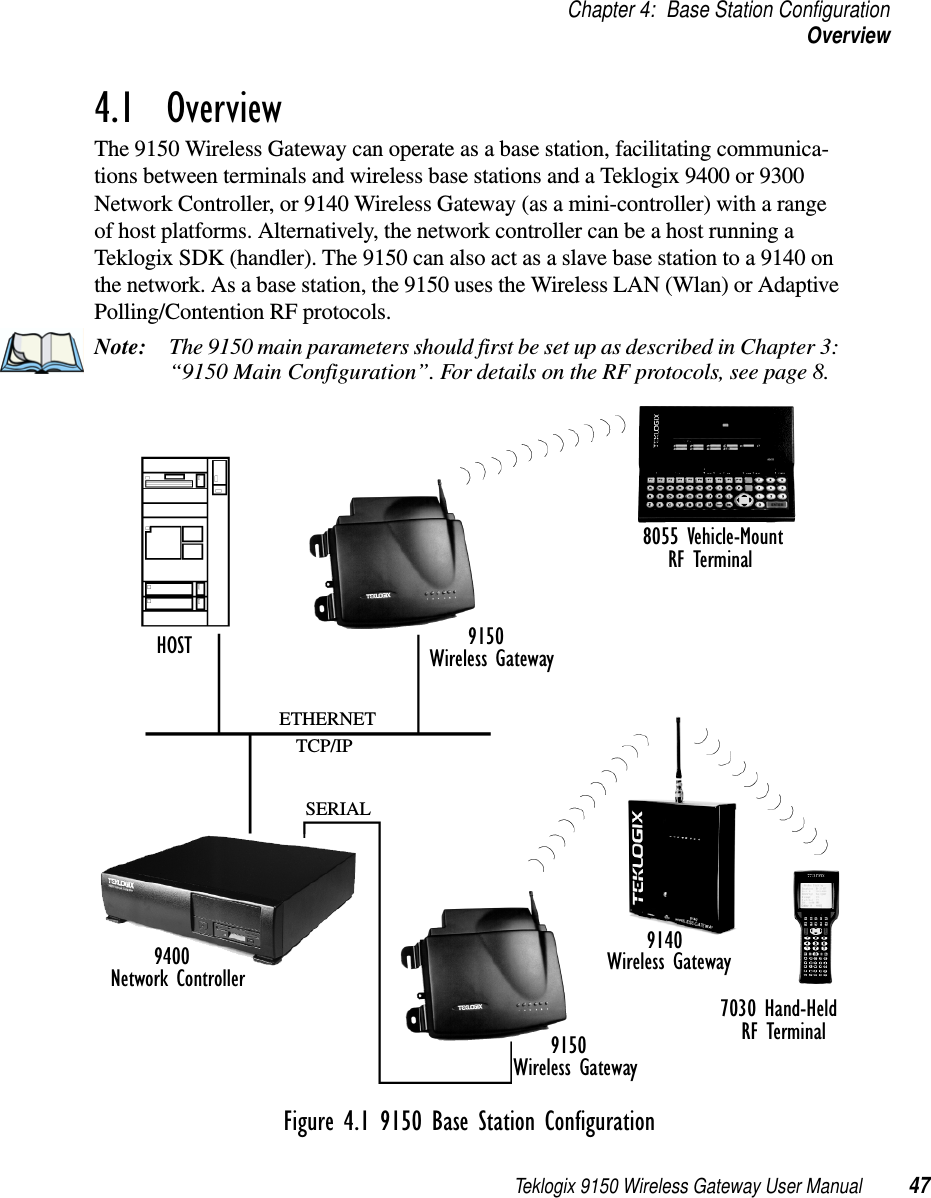
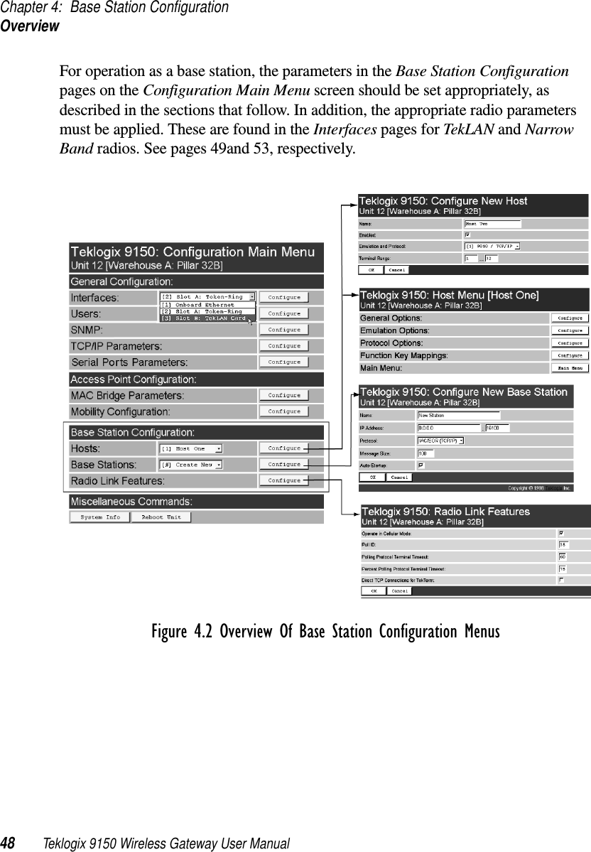
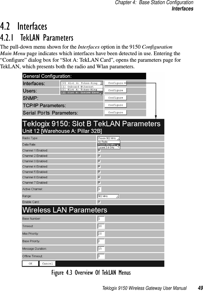
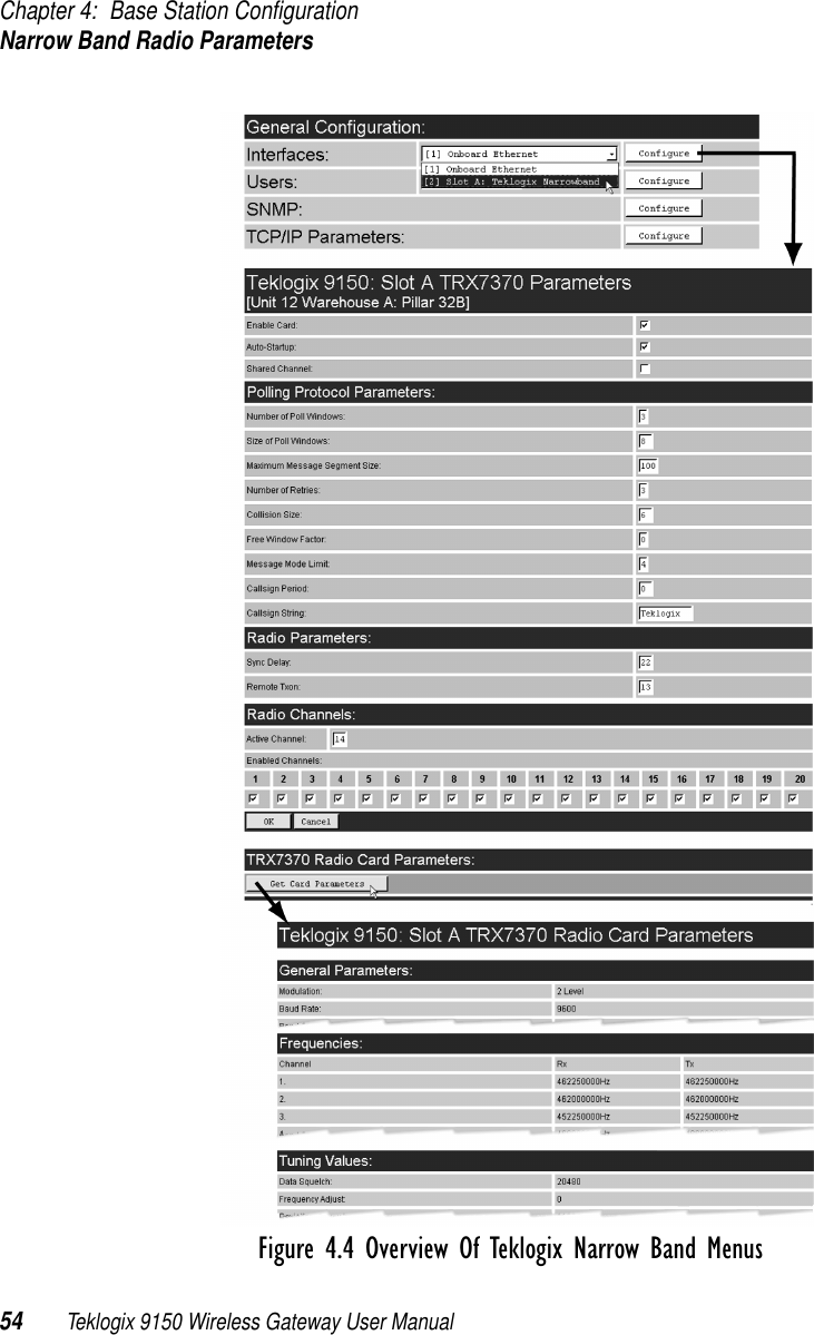
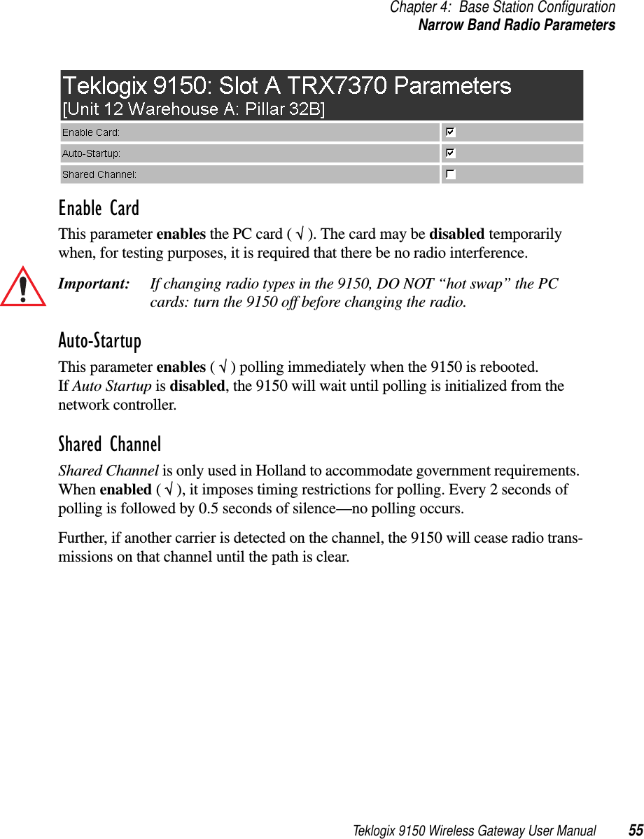
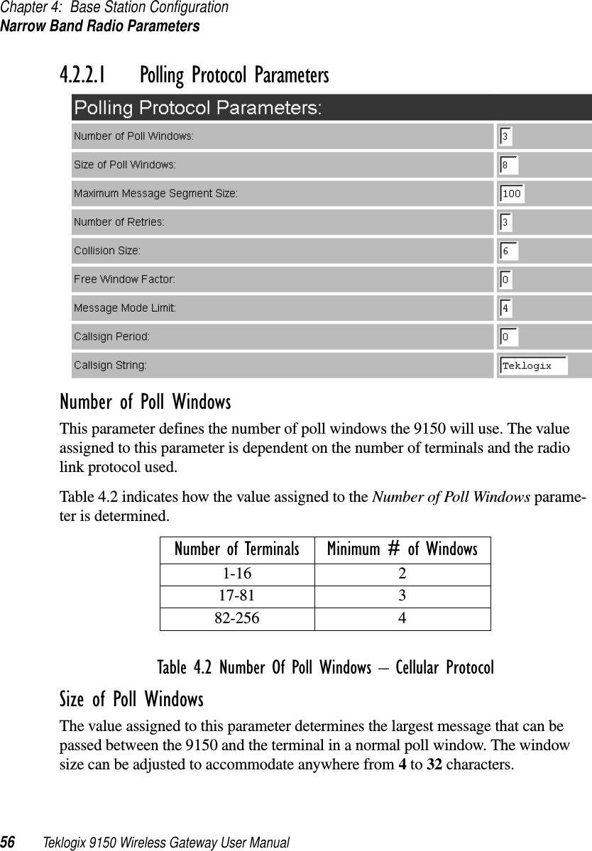
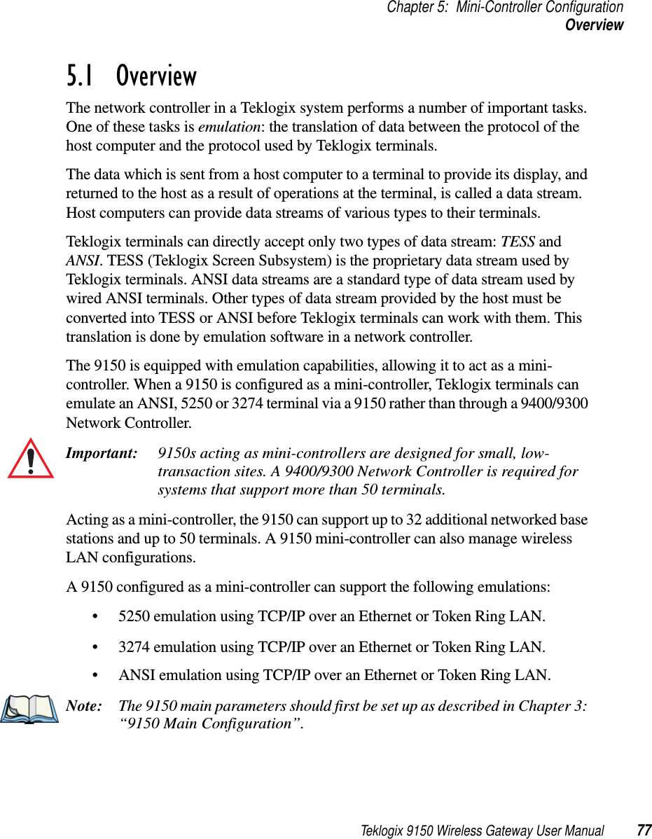
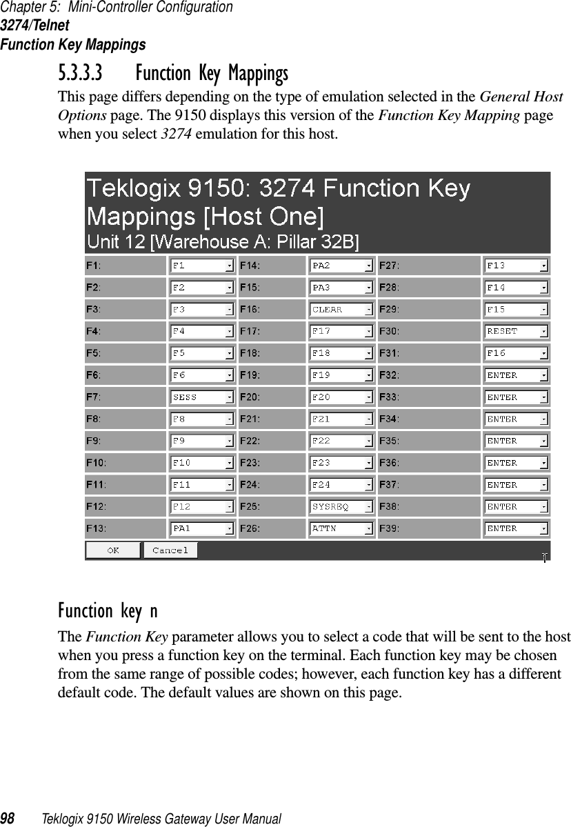
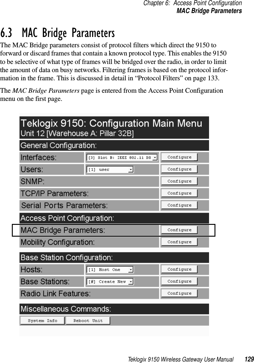
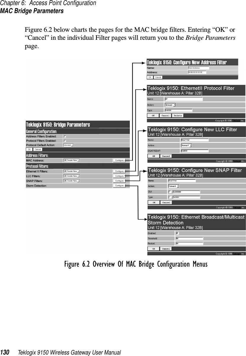
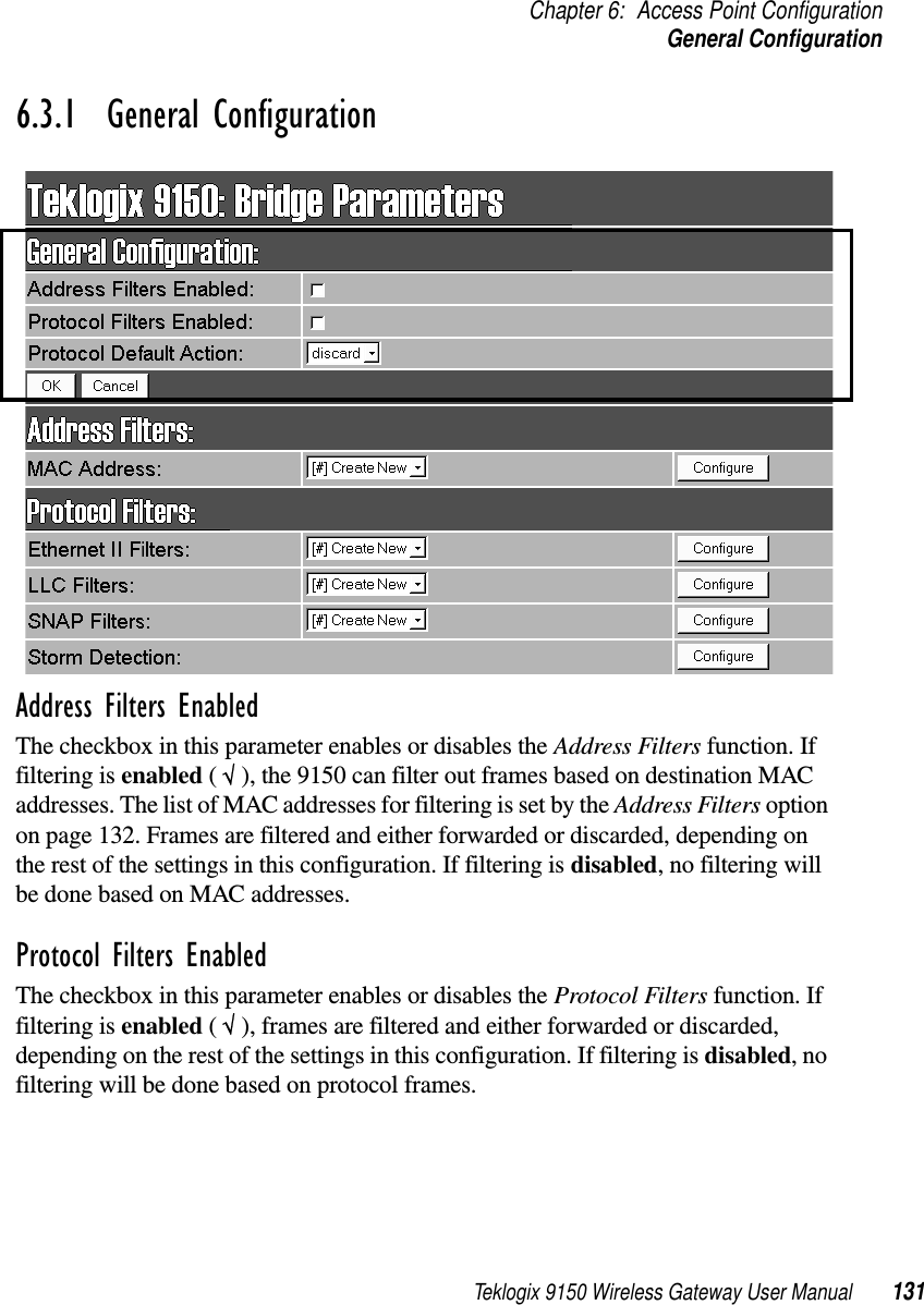
9150 User Manual
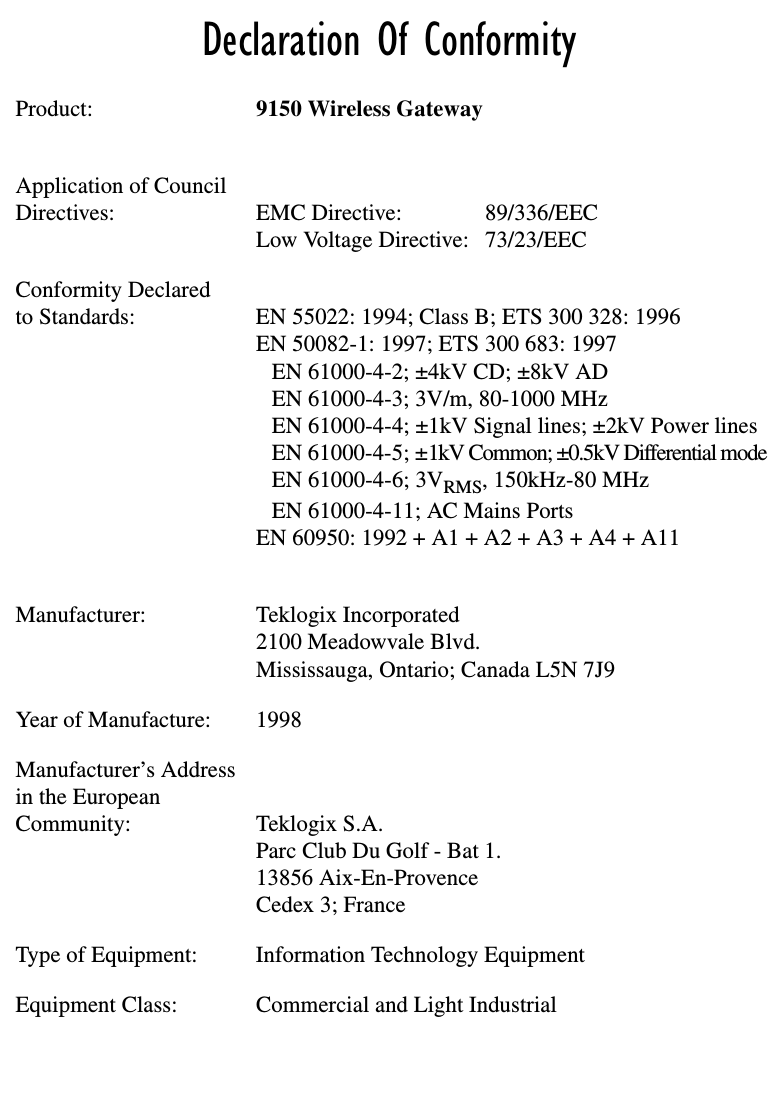
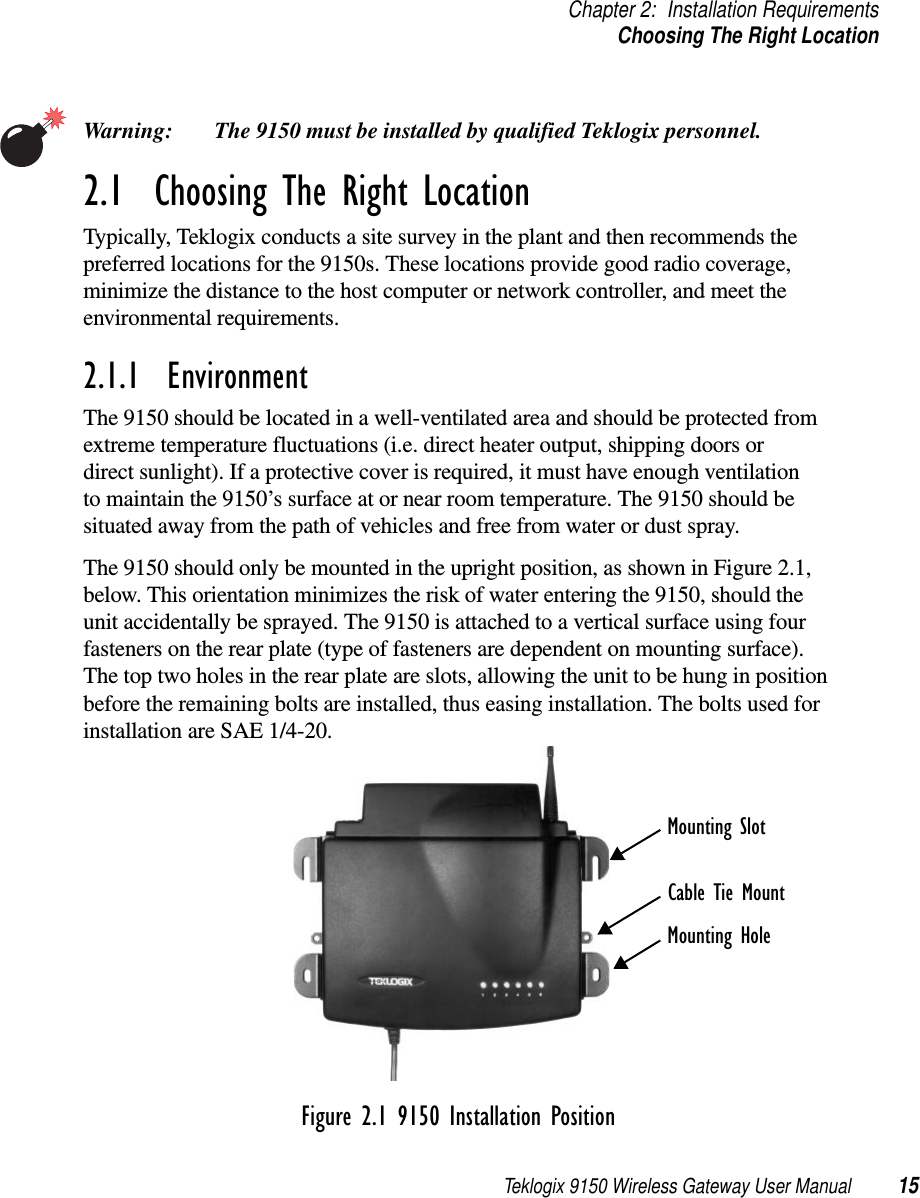
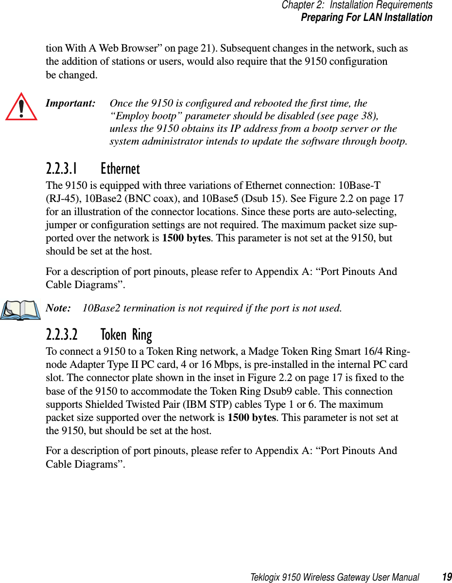
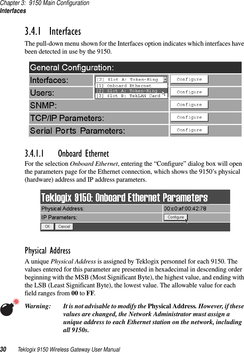
![Chapter 3: 9150 Main ConfigurationUsers34 Teklogix 9150 Wireless Gateway User Manual3.4.1.3 Slot n: PC Card RadioEach PC (PCMCIA) card radio resident in the 9150 will be located in one of two Slots: A or B. Selecting a PC card will open the sub-menu for that radio.IEEE 802.11 FH or DS: See “IEEE 802.11 (Frequency Hopping Radio Parame-ters)” on page 126, or “IEEE 802.11 (Direct Sequence Radio Parameters)” on page 128 for details on setting the radio parameters for the PC card.TekLAN Card: See “TekLAN Parameters” on page 49 for details on setting the radio and Wlan parameters.Teklogix Narrowband: See “Narrow Band Radio Parameters” on page 53 for details on setting the radio and polling parameters.3.4.2 UsersThe Users option provides security for access to the 9150 Configuration menus. New individuals can be added by selecting “[#] Create New” in the listbox before entering the “Configure” dialog box.Individual names and their assigned passwords may be changed or deleted in the “Configure” dialog box for this option by selecting the name in the listbox and then opening the “Configure” dialog box. The password can be comprised of alphanumeric characters and is case-sensitive.](https://usermanual.wiki/Psion/WLPC24H.9150-User-Manual/User-Guide-92264-Page-48.png)
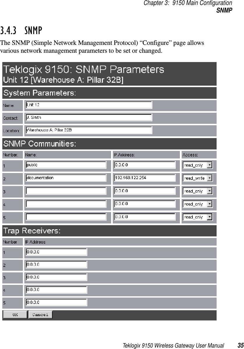
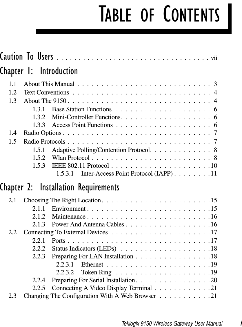
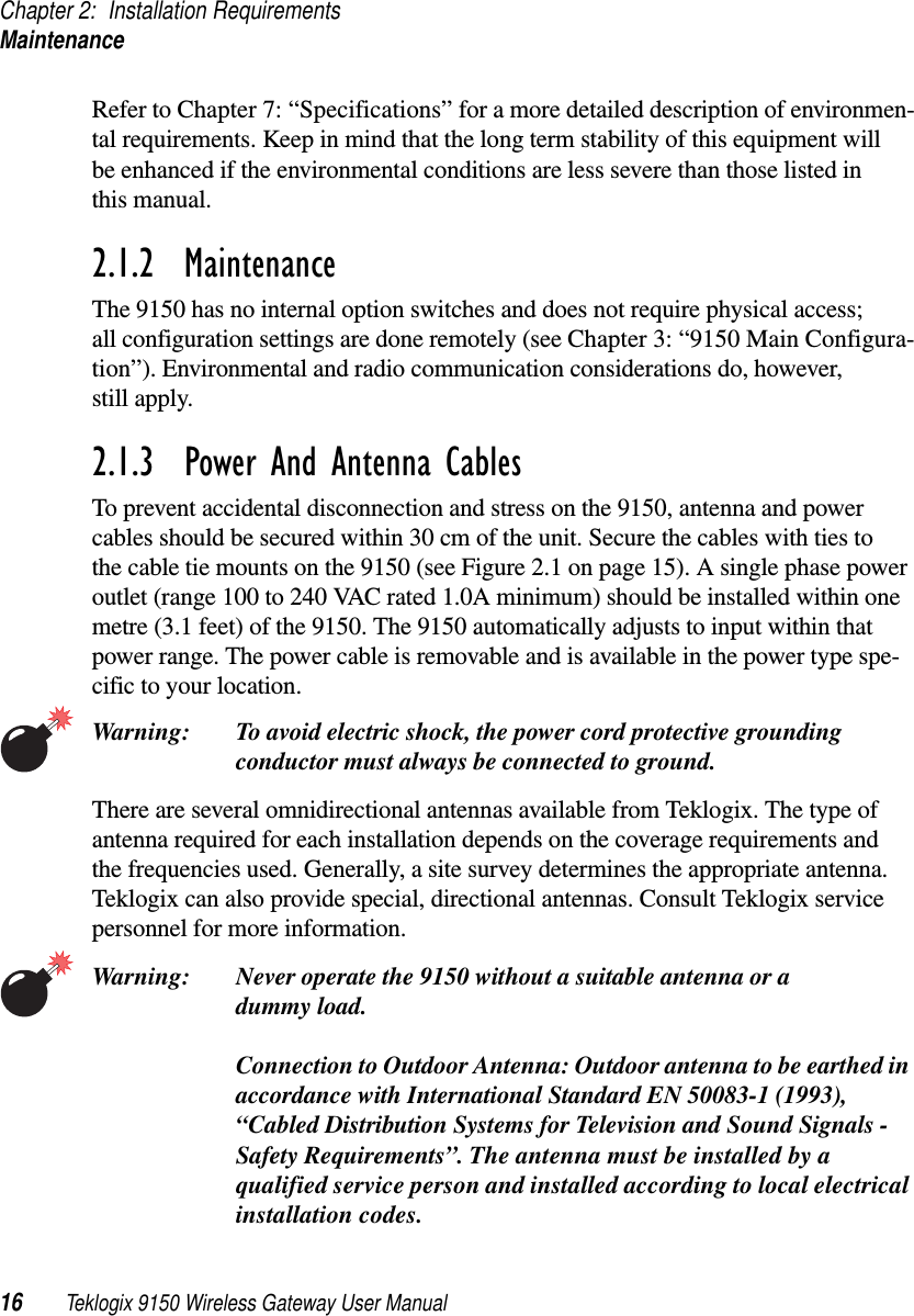
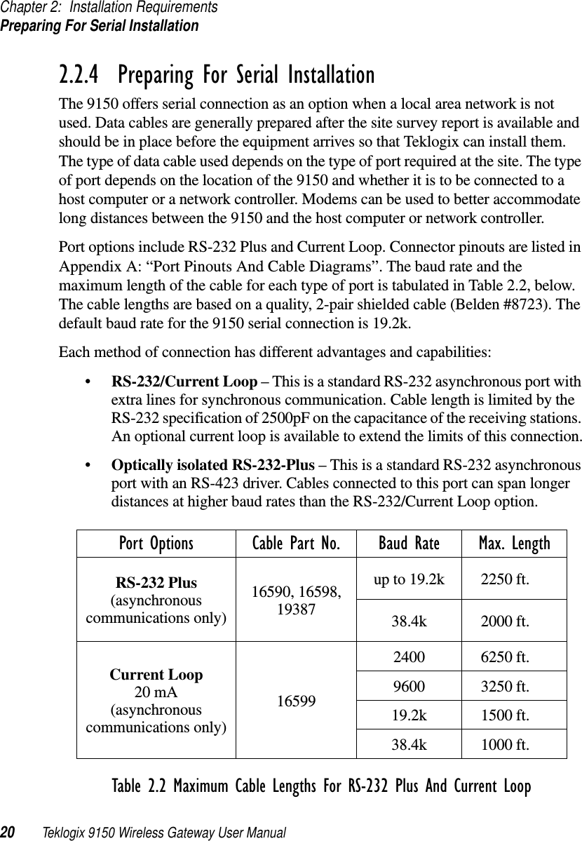
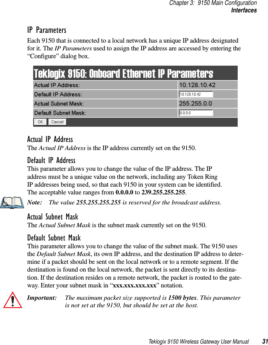
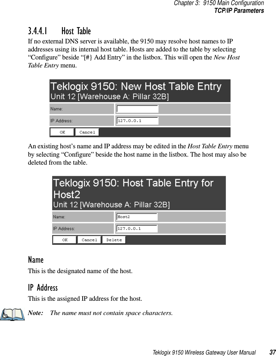
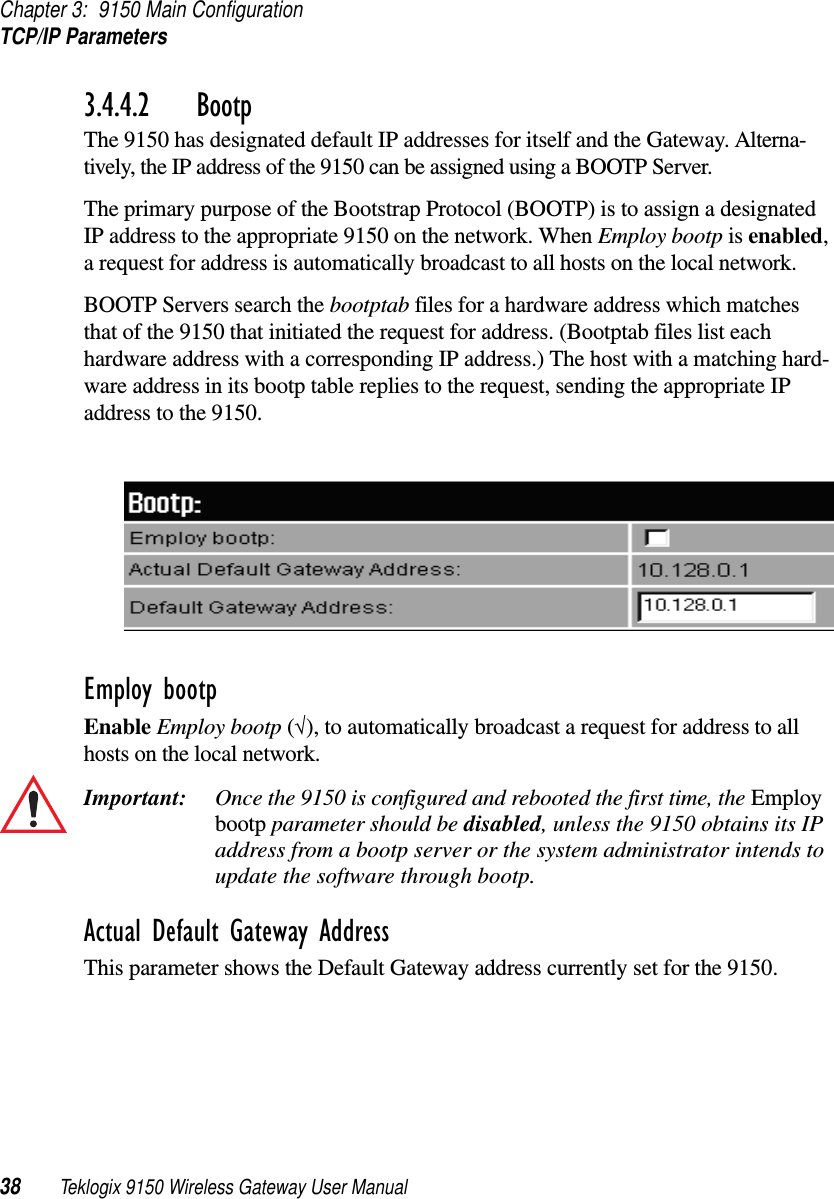
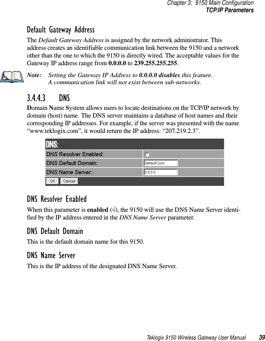
![Chapter 3: 9150 Main ConfigurationTCP/IP Parameters36 Teklogix 9150 Wireless Gateway User Manual3.4.3.1 System ParametersThe entries in these parameters set the name, contact and location identifiers for this specific 9150 Wireless Gateway. The name and location are then shown as the sub-heading of each Configuration page. In this example the identifier appears as “Unit 12 [Warehouse A: Pillar 32B]”.3.4.3.2 SNMP CommunitiesThese parameter settings allow the network administrator to define the network environment and determine the type of access allowed (read-only, or read-write) for each area name and IP address.3.4.3.3 Trap ReceiversThese IP addresses determine which SNMP manager’s stations will receive SNMP Traps from the 9150. The 9150 sends the “Cold Start” Trap on reboot or power up.3.4.4 TCP/IP ParametersThe 9150 is situated on a wired network which uses TCP/IP. Both Bootp and DNS options are available to resolve IP addressing issues.](https://usermanual.wiki/Psion/WLPC24H.9150-User-Manual/User-Guide-92264-Page-50.png)
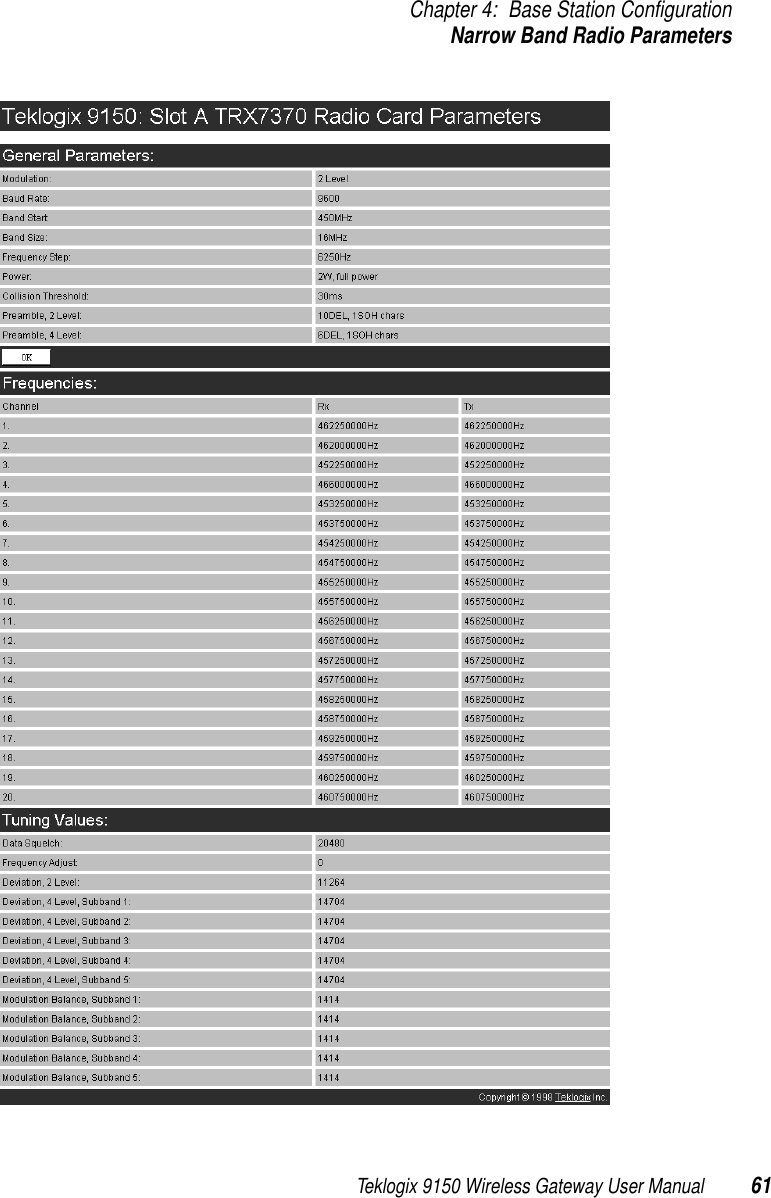
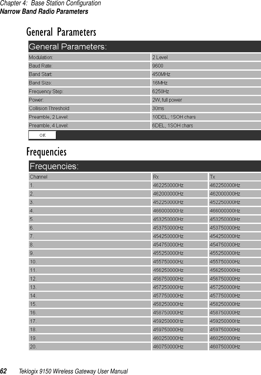
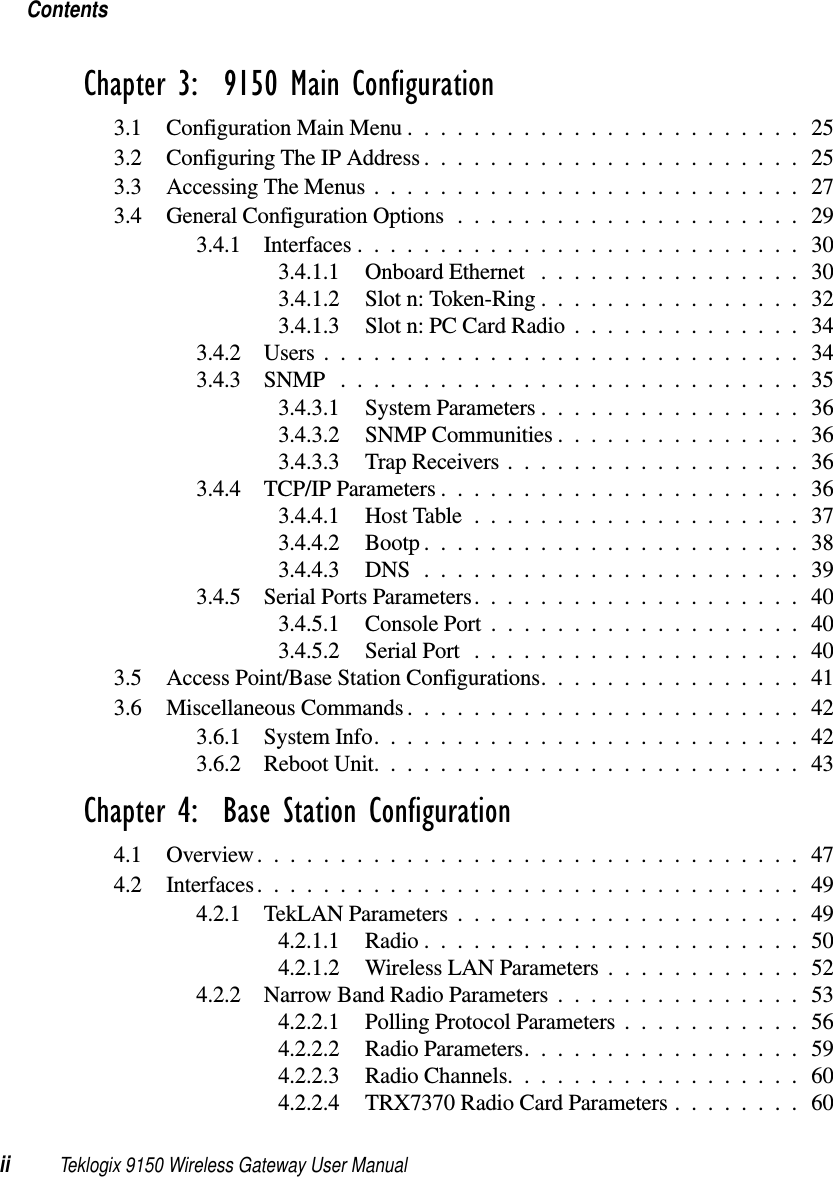
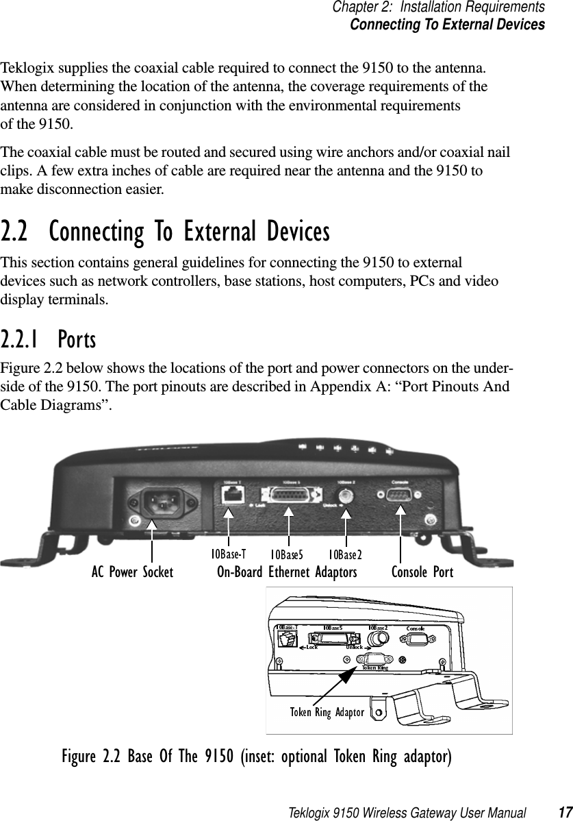
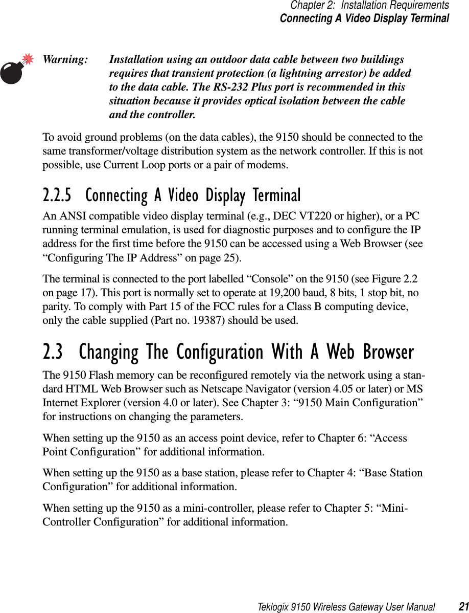
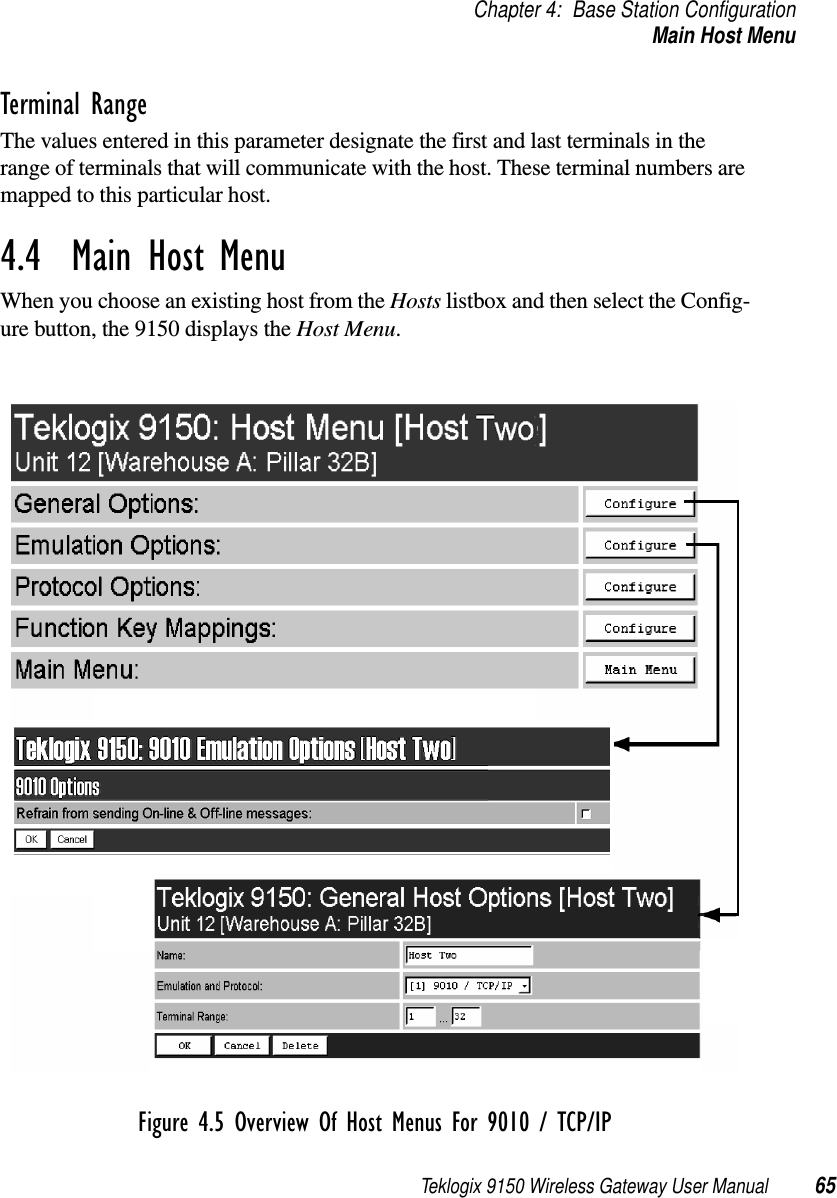
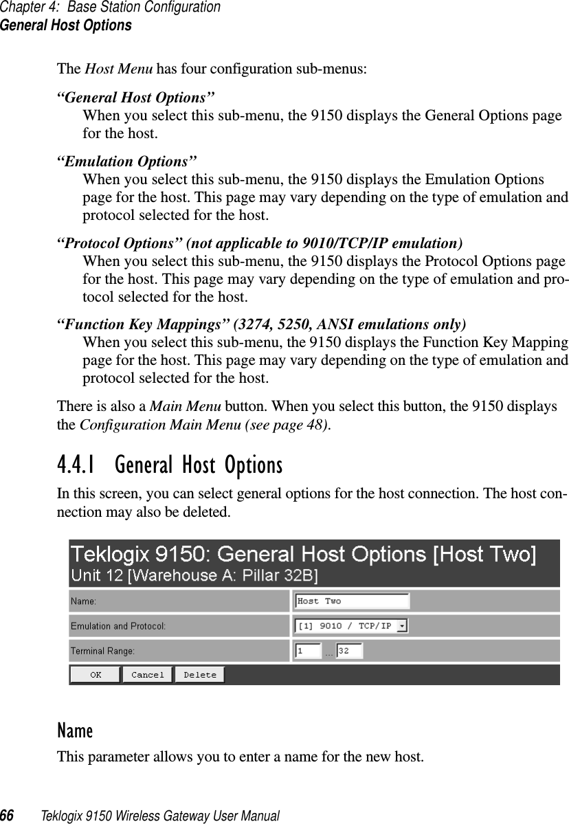
![Teklogix 9150 Wireless Gateway User Manual 63Chapter 4: Base Station ConfigurationHostsTuning Values4.3 HostsThe drop-down menu in this option shows the host names present on the system. Up to six hosts can be supported. A “host” must be configured for each master network controller, TSDK host, or master base station that communicates with the 9150. Opening the “Configure” dialog box for a selected host lists the parameters that can be modified or deleted for that host. New hosts can be added by selecting “[#] Create New” in the drop-down menu before entering the “Configure” dialog box.](https://usermanual.wiki/Psion/WLPC24H.9150-User-Manual/User-Guide-92264-Page-77.png)
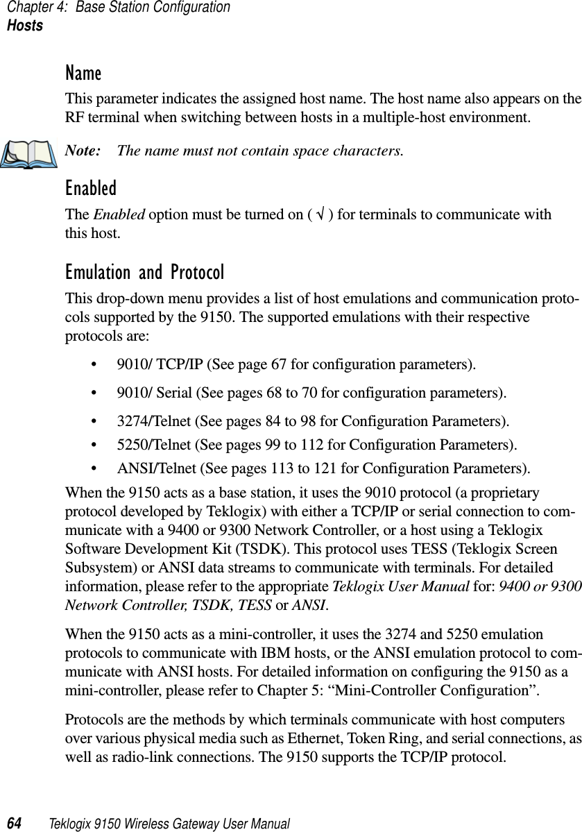
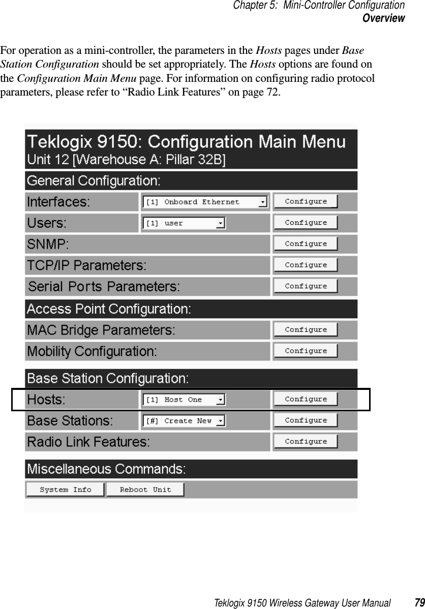
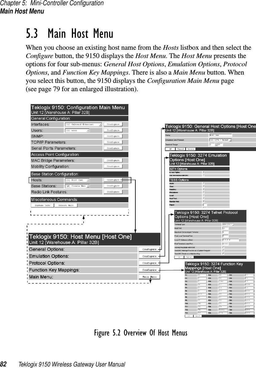
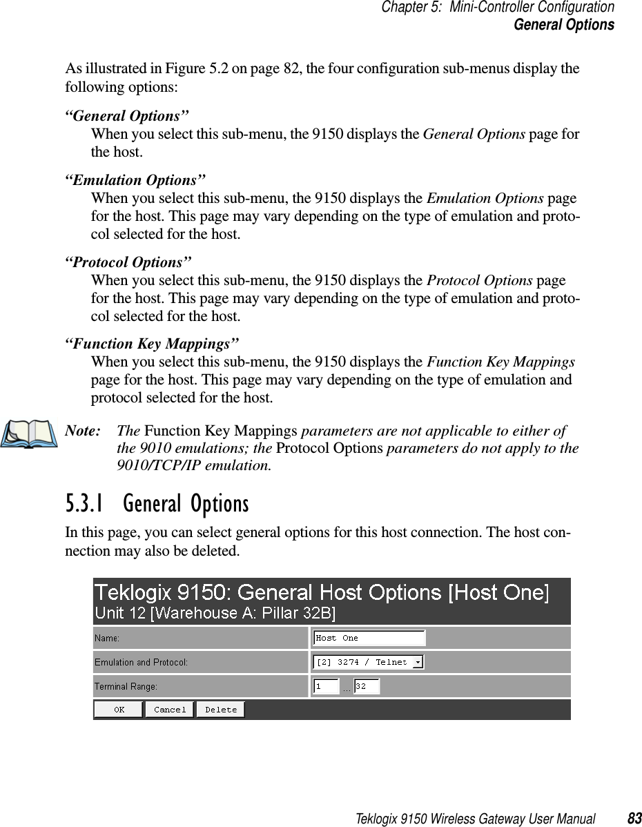
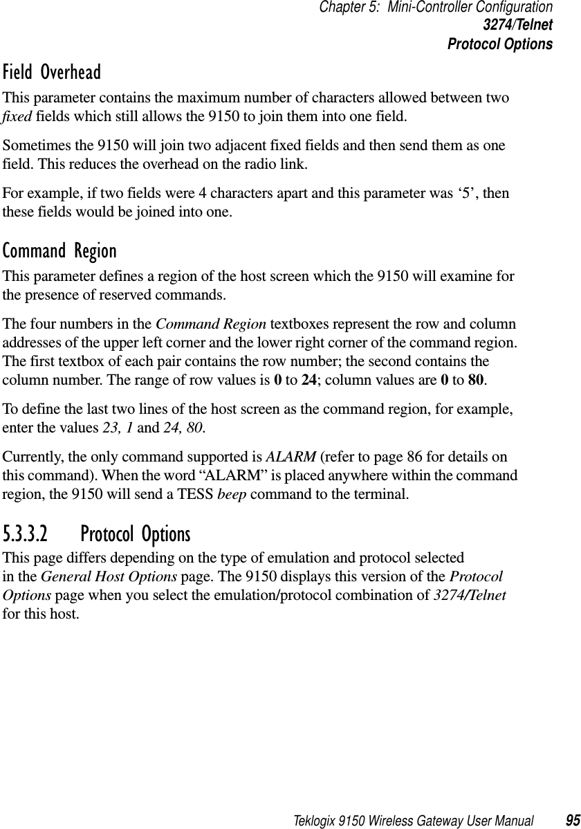
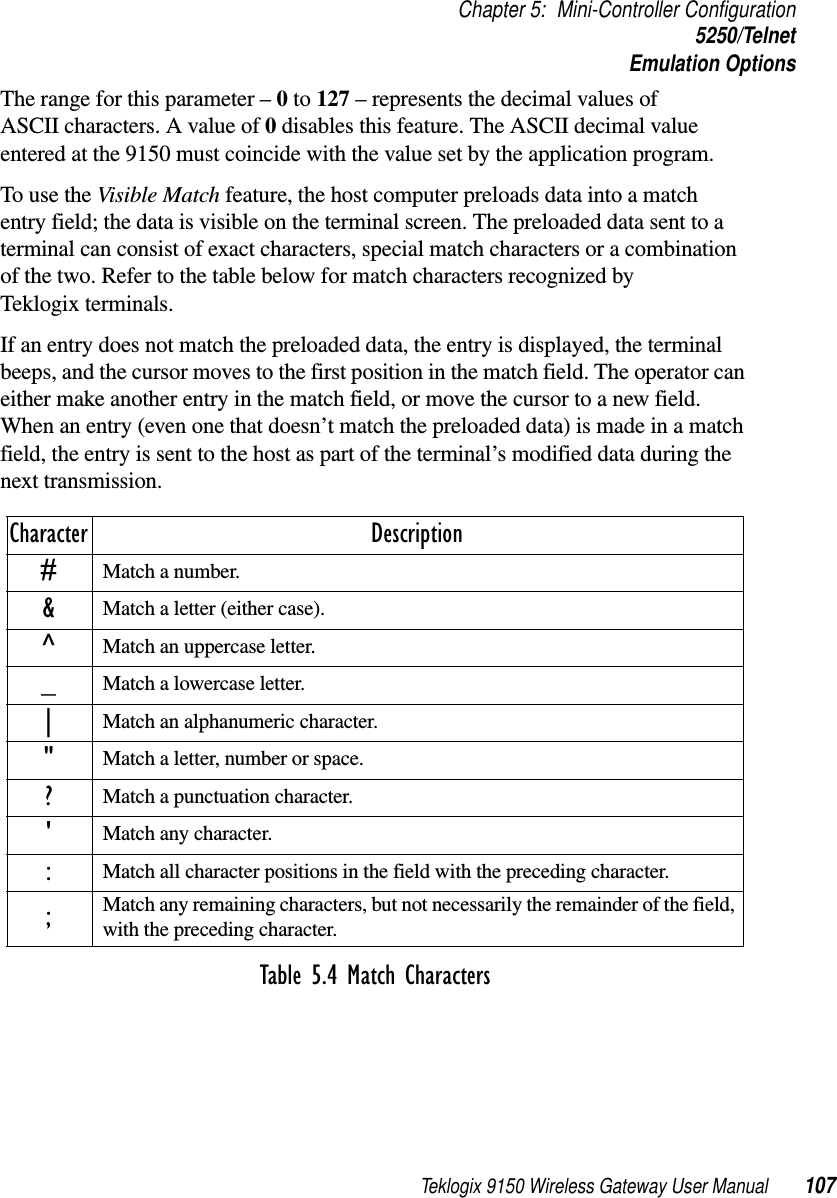
![Chapter 5: Mini-Controller ConfigurationHosts80 Teklogix 9150 Wireless Gateway User Manual5.2 HostsThe drop-down menu in this option shows the host names present on the system. Up to six hosts can be supported. A “host” must be configured for each host that com-municates with the 9150 mini-controller. Opening the Configure dialog box for a selected host lists the parameters that can be modified or deleted for that host. New hosts can be added by selecting “[#] Create New” in the drop-down menu before entering the Configure dialog box.NameThis parameter indicates the assigned host name. The host name also appears on the RF terminal when switching between hosts in a multiple-host environment.EnabledThe Enabled option must be turned on ( √ ) for terminals to communicate with this host.Emulation and ProtocolThis drop-down menu provides a list of host emulations and communication proto-cols supported by the 9150. Working with Teklogix terminals and base stations, the 9150 can emulate IBM 3278-2, 5251-11, and 5555-B01 terminals, as well as ANSI terminals.Protocols are the methods by which terminals communicate with host computers over various physical media such as Ethernet, Token Ring, and serial connections, as well as radio-link connections. The 9150 supports the TCP/IP protocol.](https://usermanual.wiki/Psion/WLPC24H.9150-User-Manual/User-Guide-92264-Page-94.png)
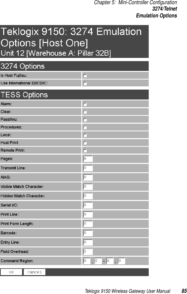
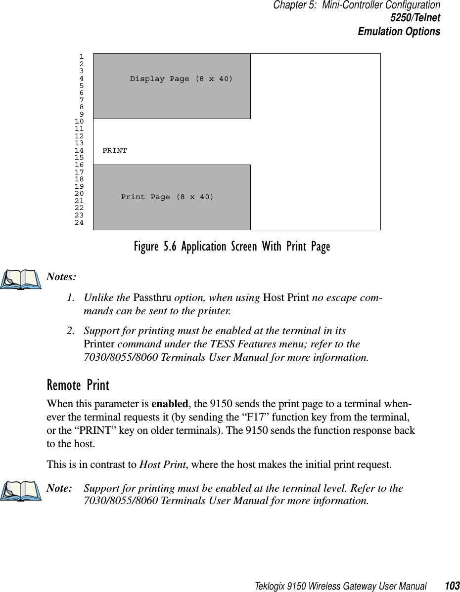
![Chapter 5: Mini-Controller Configuration3274/TelnetEmulation Options86 Teklogix 9150 Wireless Gateway User ManualIs Host Fujitsu If this parameter is enabled, the 9150 mini-controller sends its data in Fujitsu format. Enabling this parameter causes the standard IBM formatting codes (for start of field, setting buffers, etc.) to be replaced by the codes used by Fujitsu host computers.Use International EBCDIC If this parameter is enabled, the 9150 mini-controller uses the International EBCDIC character set, swapping the positions of the ! and ] characters. Alarm When this parameter is enabled, terminals beep when the word “ALARM” appears on the application screen in the location specified by the Command Region parame-ter (see page 95). The word “ALARM” should be a display-only field.Note: The Command Region parameter must be enabled for this parameter to work.Clear If this parameter is enabled, the 9150 mini-controller creates an empty entry field for an entry field that is filled with spaces.Some host applications rely on the video attributes of displayed characters to high-light fields, particularly entry fields. For example, the application screen may define all entry fields with reverse video and fill the field with spaces. This is effective on terminals that support reverse video, but on terminals that do not, it can make the field invisible since it is made up entirely of spaces.By default, all empty entry fields displayed at the Teklogix terminal are highlighted by the “entry character” chosen in the terminal’s configuration (not all Teklogix ter-minals support video attributes). Note: This operation is only performed on screens received from the host. Data sent to the host remains unaffected.Passthru If this parameter is enabled, the 9150 allows the host to send data directly to the RF terminal’s serial port. This is most commonly used for printing.](https://usermanual.wiki/Psion/WLPC24H.9150-User-Manual/User-Guide-92264-Page-100.png)
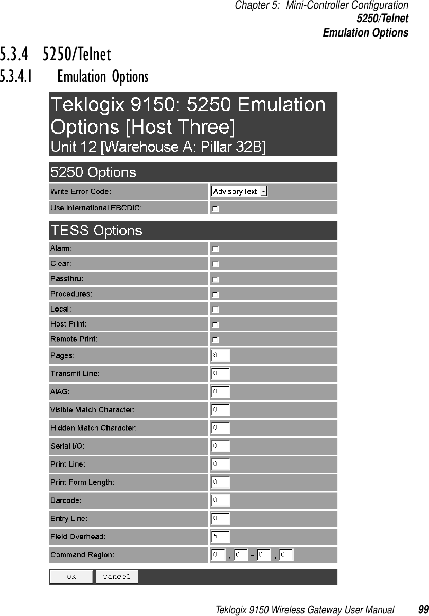
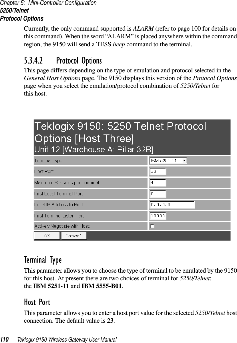
![Chapter 5: Mini-Controller Configuration5250/TelnetEmulation Options100 Teklogix 9150 Wireless Gateway User ManualThe 9150 displays this version of the Emulation Options page after you have selected the 5250/Telnet emulation/protocol combination for this host connection.With IBM 5250, or IBM 3274 emulation, the 9150 mini-controller converts the application data stream from the host to TESS (Teklogix Screen Subsystem) commands. Some of the parameters in this page govern the conversion of the host screens to TESS.Write Error Code If advisory text is selected here, the 9150 sends error codes to the terminal screen as advisory text, which is written at the bottom of the screen. If screen text is chosen, the 9150 sends the error codes as regular screen text.Use International EBCDIC If this parameter is enabled, the 9150 will swap the positions of the ! and ] charac-ters in the EBCDIC character table.Alarm If this parameter is enabled, terminals will beep when the word “ALARM” (in capital letters) appears on the application screen, in the location specified by the Command Region parameter (see page 109). The word “ALARM” should be a display-only field.Note: The Command Region parameter must be enabled for this parameter to work.Clear If this parameter is enabled, the 9150 mini-controller creates an empty entry field for an entry field that is filled with spaces.Some host applications rely on the video attributes of displayed characters to high-light fields, particularly entry fields. For example, the application screen may define all entry fields with reverse video and fill the field with spaces. This is effective on terminals that support reverse video, but on terminals that do not, it can make the field invisible since it is made up entirely of spaces.](https://usermanual.wiki/Psion/WLPC24H.9150-User-Manual/User-Guide-92264-Page-114.png)

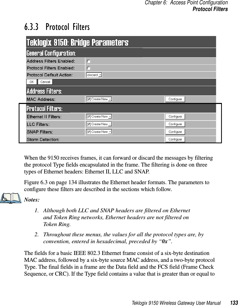
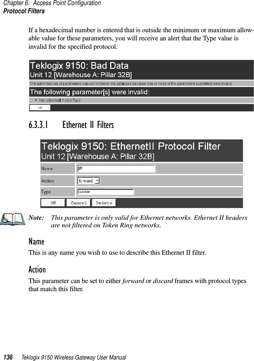
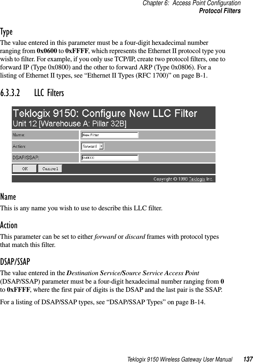
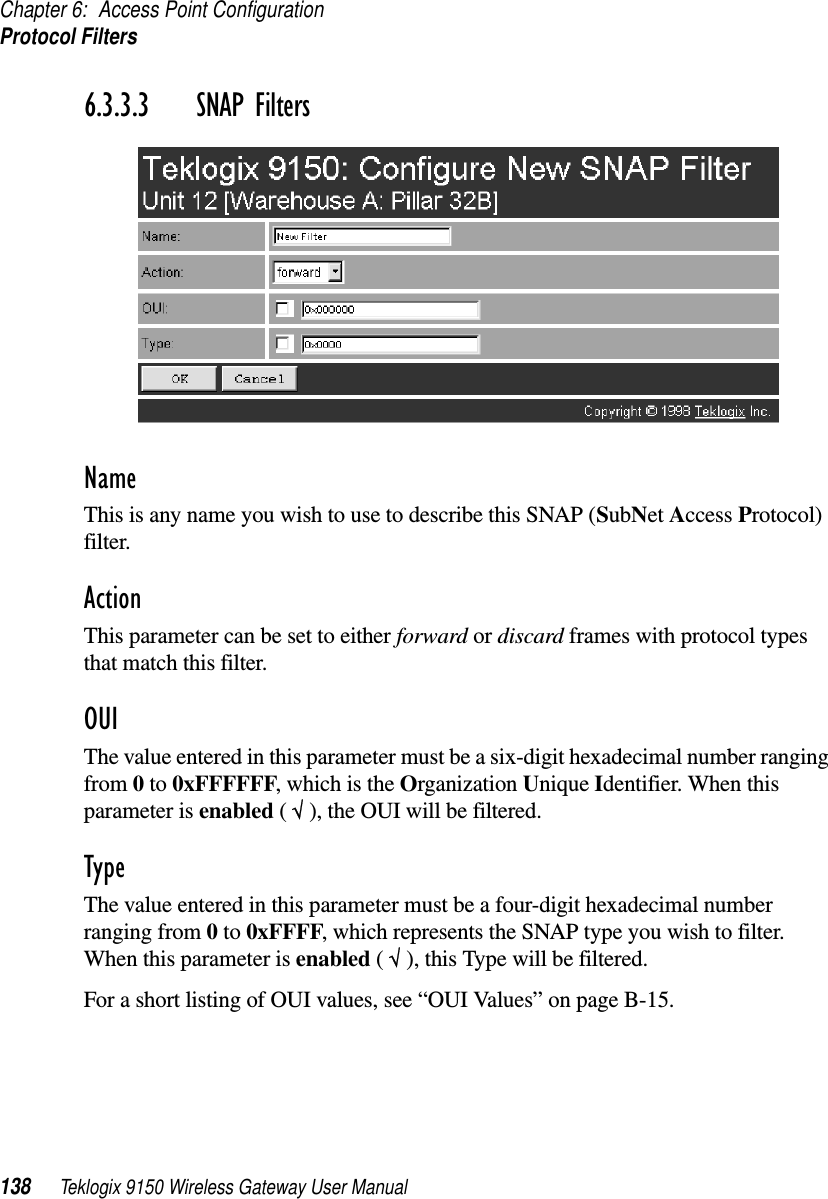
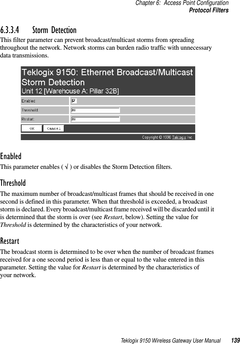
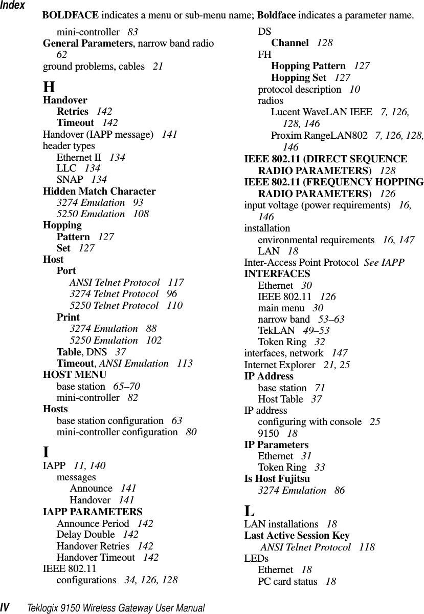
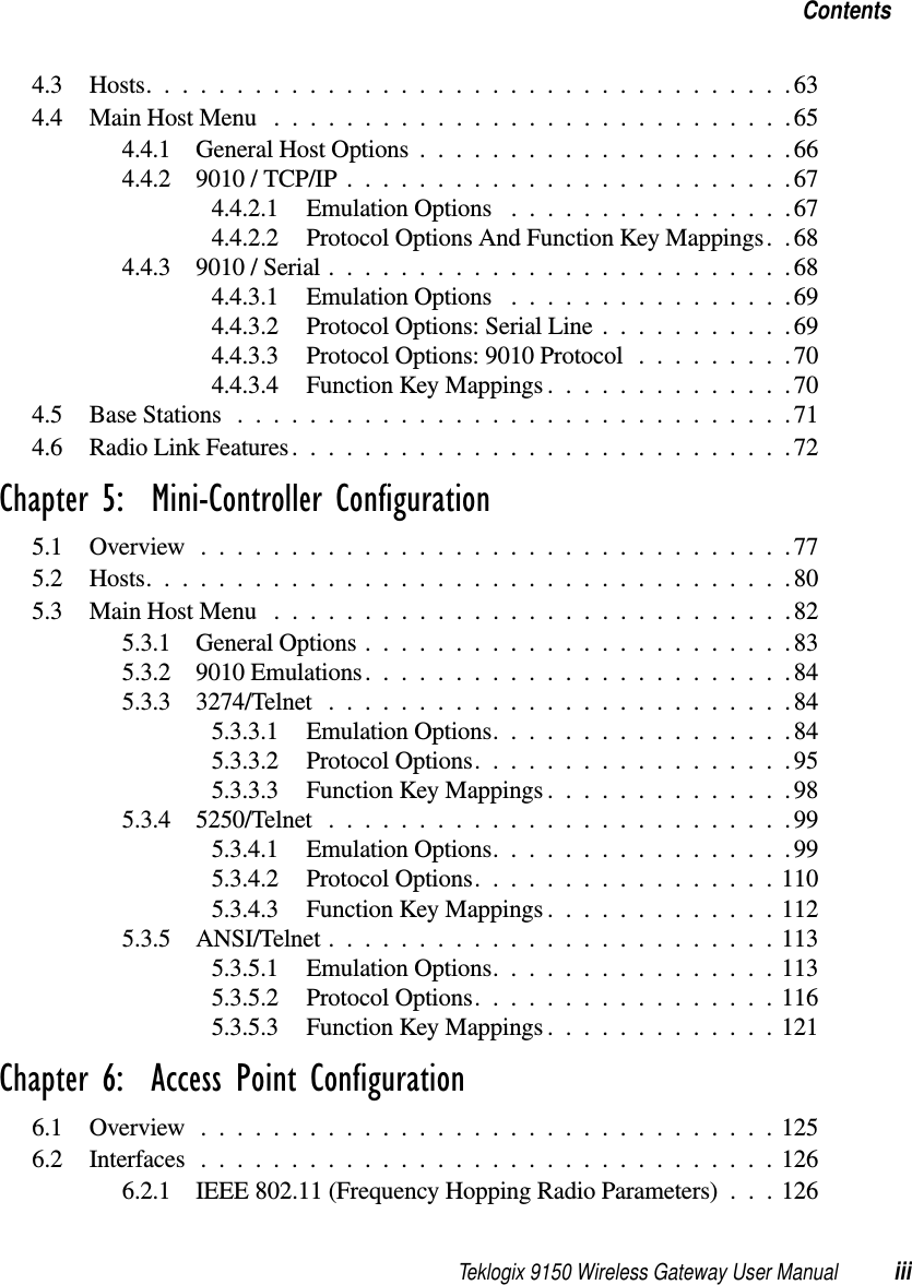
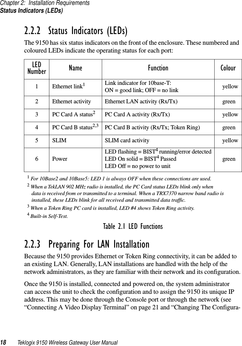
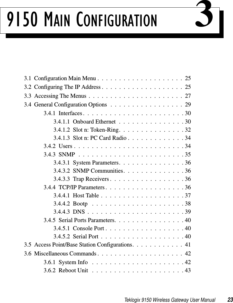
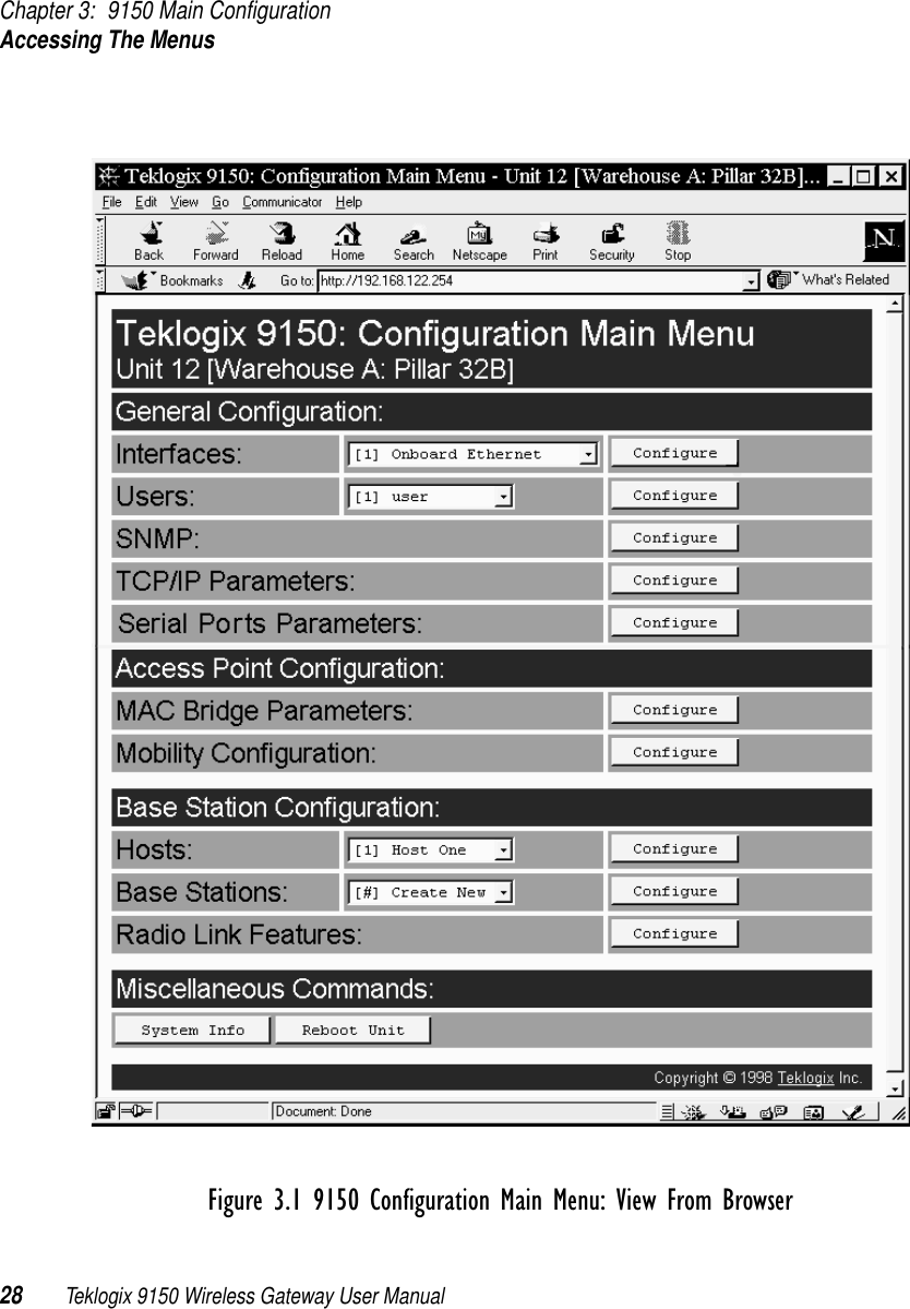
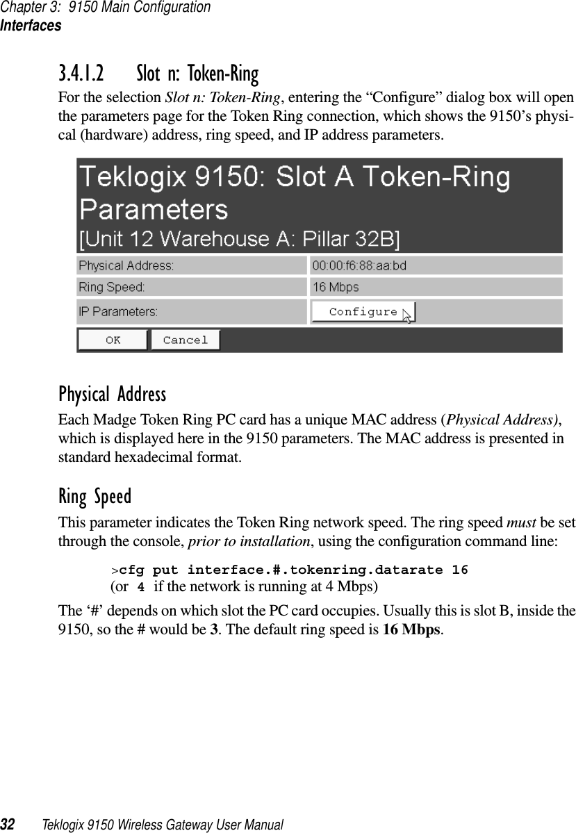
![Teklogix 9150 Wireless Gateway User Manual 135Chapter 6: Access Point ConfigurationProtocol FiltersFigure 6.4 Protocol Filters Main Menu And Sub-menusNew filters can be added by selecting “[#] Create New” in the listbox before enter-ing the “Configure” dialog box.](https://usermanual.wiki/Psion/WLPC24H.9150-User-Manual/User-Guide-92264-Page-149.png)