Psion WLPC24H User Manual 80440 6 access

Psion Inc 80440 6 access

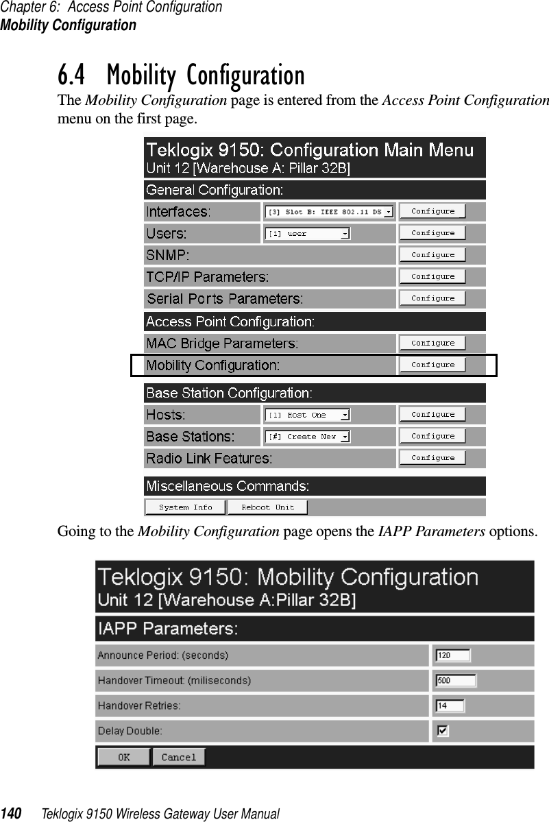
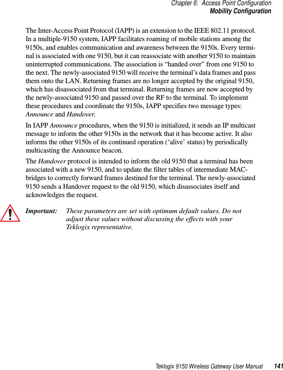
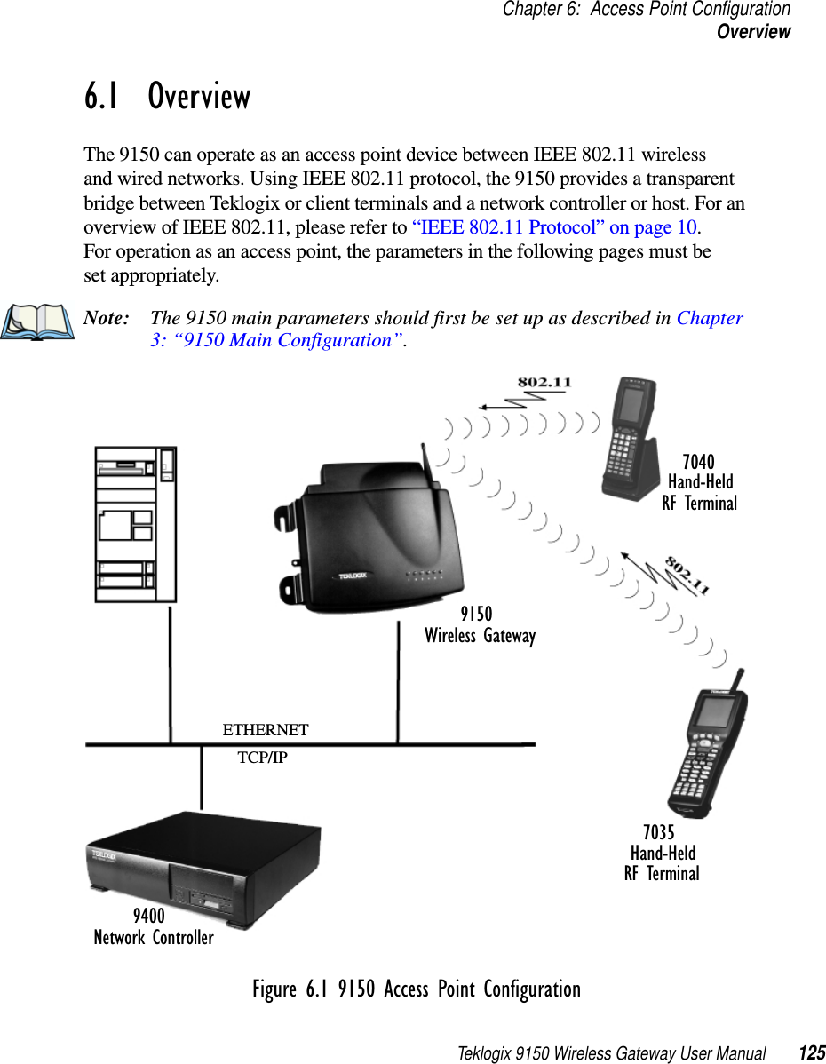
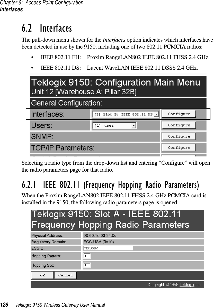
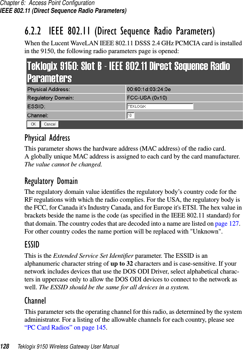
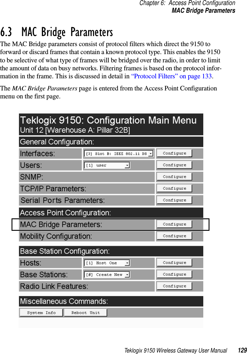
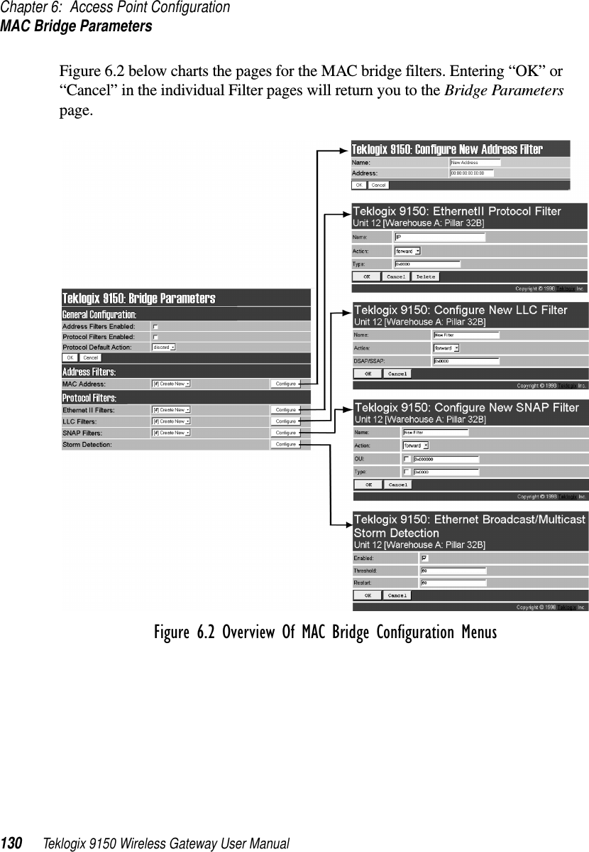
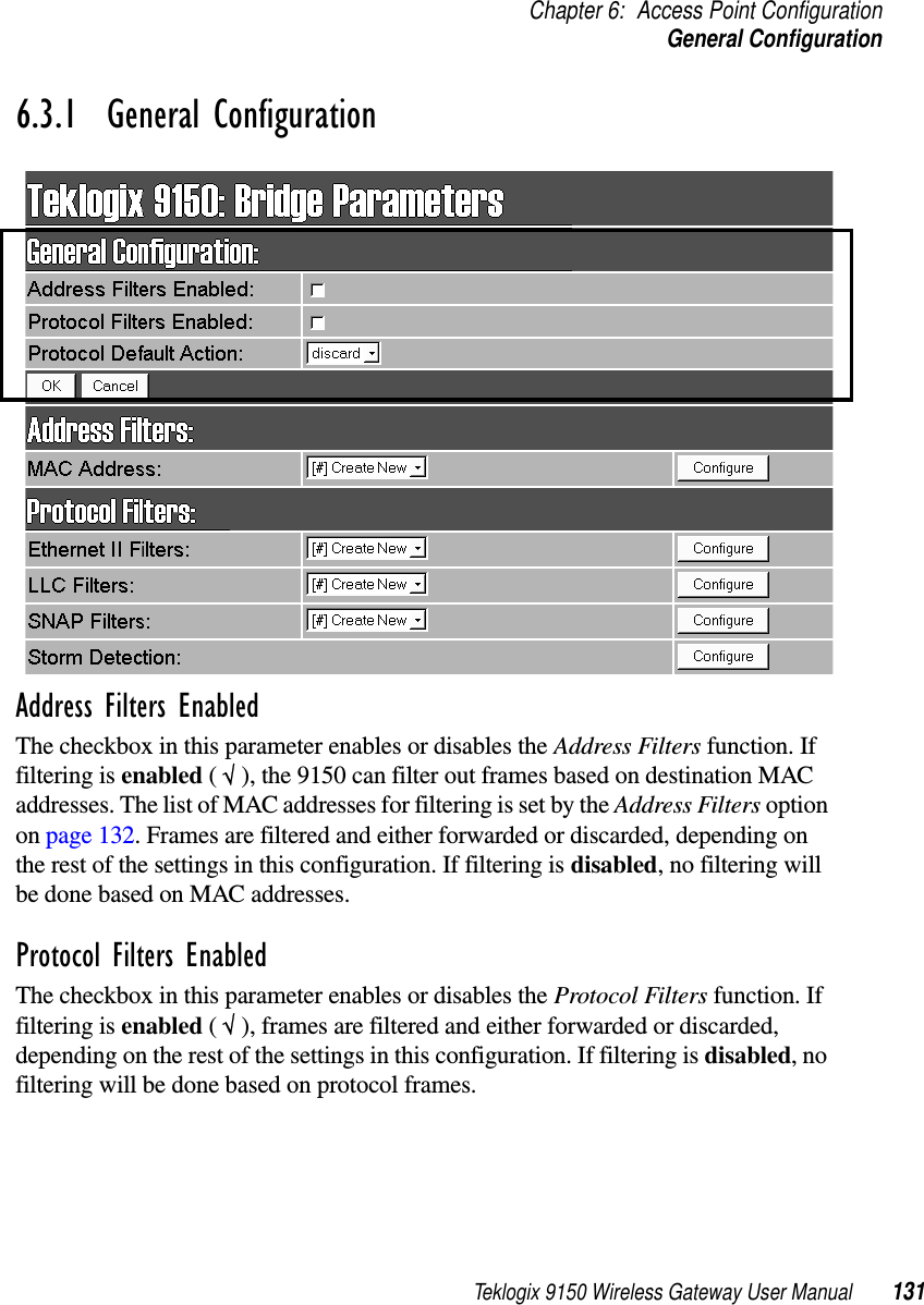
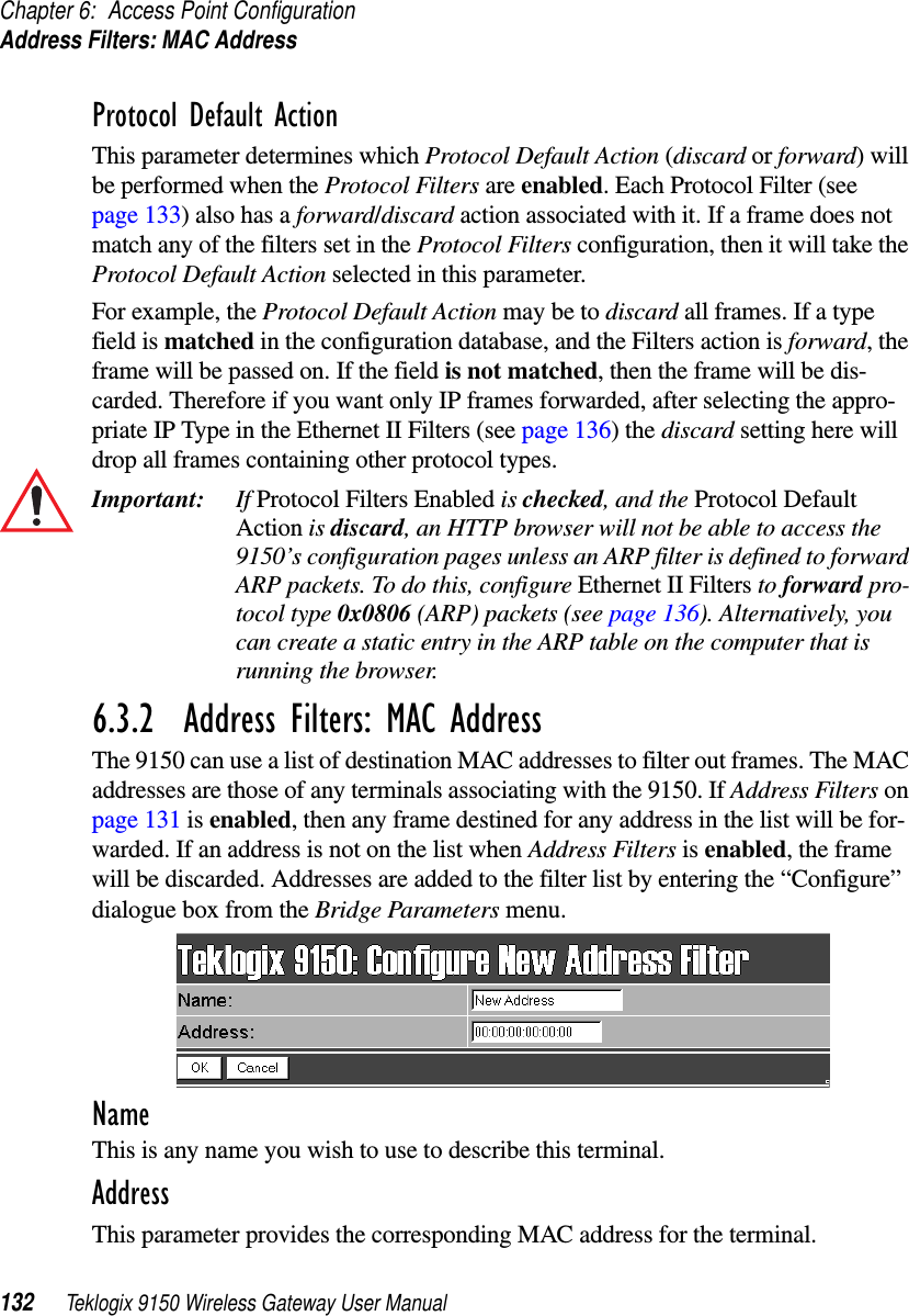
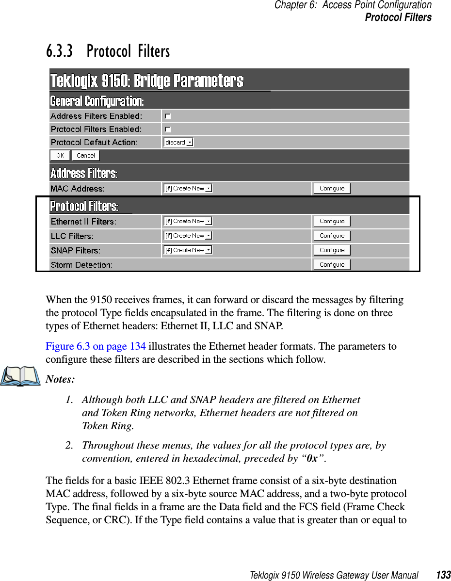
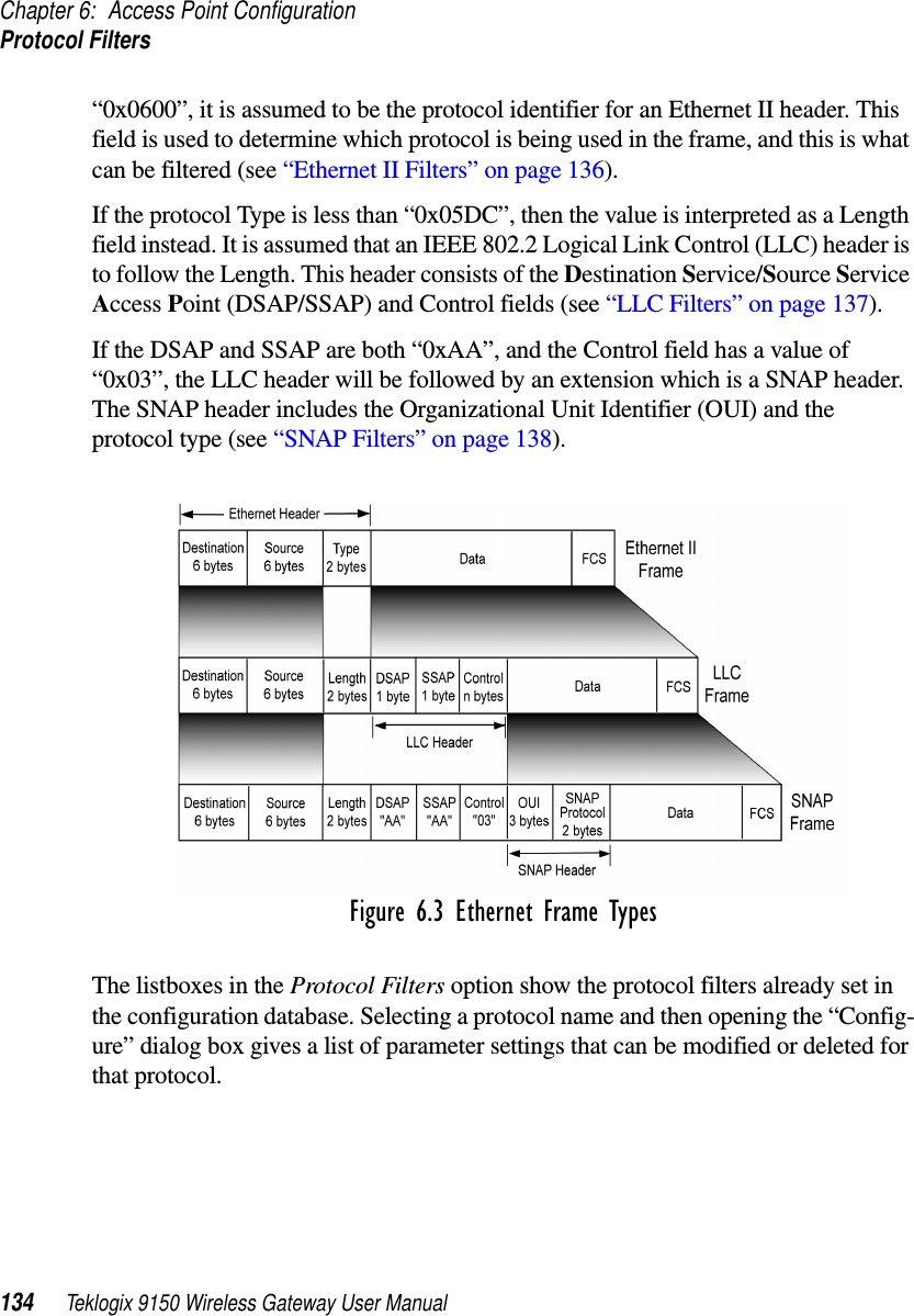
Teklogix 9150 Wireless Gateway User Manual Chapter 6 Access Point Configuration

Teklogix 9150 Wireless Gateway User Manual 123ACCESS POINT CONFIGURATION 66.1  Overview..............................1256.2  Interfaces..............................1266.2.1  IEEE 802.11 (Frequency Hopping Radio Parameters) . . 1266.2.2  IEEE 802.11 (Direct Sequence Radio Parameters) . . . . 1286.3  MAC Bridge Parameters......................1296.3.1  General Configuration . . . . . . . . . . . . . . . . . 1316.3.2  Address Filters: MAC Address . . . . . . . . . . . . 1326.3.3  Protocol Filters.....................1336.3.3.1  Ethernet II Filters . . . . . . . . . . . . . . . . 1366.3.3.2  LLC Filters ...................1376.3.3.3  SNAP Filters...................1386.3.3.4  Storm Detection.................1396.4  Mobility Configuration ......................1406.4.1  IAPP Parameters....................142
Teklogix 9150 Wireless Gateway User Manual 125Chapter 6: Access Point ConfigurationOverview6.1  OverviewThe 9150 can operate as an access point device between IEEE 802.11 wireless and wired networks. Using IEEE 802.11 protocol, the 9150 provides a transparent bridge between Teklogix or client terminals and a network controller or host. For an overview of IEEE 802.11, please refer to “IEEE 802.11 Protocol” on page 10. For operation as an access point, the parameters in the following pages must be set appropriately.Note: The 9150 main parameters should first be set up as described in Chapter 3: “9150 Main Configuration”.Figure 6.1 9150 Access Point ConfigurationETHERNETTCP/IP9150Wireless GatewayRF Terminal7040Network ControllerRF Terminal70359400Hand-HeldHand-Held
Chapter 6: Access Point ConfigurationInterfaces126 Teklogix 9150 Wireless Gateway User Manual6.2  InterfacesThe pull-down menu shown for the Interfaces option indicates which interfaces have been detected in use by the 9150, including one of two 802.11 PCMCIA radios:•IEEE 802.11 FH: Proxim RangeLAN802 IEEE 802.11 FHSS 2.4 GHz.•IEEE 802.11 DS: Lucent WaveLAN IEEE 802.11 DSSS 2.4 GHz.Selecting a radio type from the drop-down list and entering “Configure” will open the radio parameters page for that radio.6.2.1  IEEE 802.11 (Frequency Hopping Radio Parameters)When the Proxim RangeLAN802 IEEE 802.11 FHSS 2.4 GHz PCMCIA card is installed in the 9150, the following radio parameters page is opened:
Teklogix 9150 Wireless Gateway User Manual 127Chapter 6: Access Point ConfigurationIEEE 802.11 (Frequency Hopping Radio Parameters)Physical AddressThis parameter shows the hardware address (MAC address) of the radio card. A globally unique MAC address is assigned to each card by the card manufacturer. The value cannot be changed.Regulatory DomainThe regulatory domain value identifies the regulatory body’s country code for the RF regulations with which the radio complies. For the USA, the regulatory body is the FCC, for Canada it's Industry Canada, and for Europe it's ETSI. The hex value in brackets beside the name is the code (as specified in the IEEE 802.11 standard) for that domain. The country codes that are decoded into a name are listed below.  For other country codes the name portion will be replaced with "Unknown". ESSIDThis is the Extended Service Set Identifier parameter. The ESSID is an alphanumeric character string of up to 32 characters and is case-sensitive. If your network includes devices that use the DOS ODI Driver, select alphabetical charac-ters in uppercase only to allow the DOS ODI devices to connect to the network as well. The ESSID should be the same for all devices in a system. Hopping PatternThe combined settings for the Hopping Pattern and Hopping Set parameters deter-mine the operating channel for a radio using frequency hopping. Please refer to your network administrator for details.Hopping SetThe combined settings for the Hopping Set and Hopping Pattern parameters deter-mine the operating channel for a radio using frequency hopping. Please refer to your system administrator for details.Regulatory Body Domain Code CountryFCC-USA 0x10 USA (for DS radios this is also the code used for Canada) Industry Canada  0x20 Canada (currently only for FH radios, this may change in the future) ETSI-Europe  0x30 Most of Europe Spain 0x31 SpainFrance 0x32 FranceMKK-Japan 0x40 Japan
Chapter 6: Access Point ConfigurationIEEE 802.11 (Direct Sequence Radio Parameters)128 Teklogix 9150 Wireless Gateway User Manual6.2.2  IEEE 802.11 (Direct Sequence Radio Parameters)When the Lucent WaveLAN IEEE 802.11 DSSS 2.4 GHz PCMCIA card is installed in the 9150, the following radio parameters page is opened:Physical AddressThis parameter shows the hardware address (MAC address) of the radio card. A globally unique MAC address is assigned to each card by the card manufacturer. The value cannot be changed.Regulatory DomainThe regulatory domain value identifies the regulatory body’s country code for the RF regulations with which the radio complies. For the USA, the regulatory body is the FCC, for Canada it's Industry Canada, and for Europe it's ETSI. The hex value in brackets beside the name is the code (as specified in the IEEE 802.11 standard) for that domain. The country codes that are decoded into a name are listed on page 127.  For other country codes the name portion will be replaced with "Unknown".ESSIDThis is the Extended Service Set Identifier parameter. The ESSID is an alphanumeric character string of up to 32 characters and is case-sensitive. If your network includes devices that use the DOS ODI Driver, select alphabetical charac-ters in uppercase only to allow the DOS ODI devices to connect to the network as well. The ESSID should be the same for all devices in a system. ChannelThis parameter sets the operating channel for this radio, as determined by the system administrator. For a listing of the allowable channels for each country, please see “PC Card Radios” on page 145.
Teklogix 9150 Wireless Gateway User Manual 129Chapter 6: Access Point ConfigurationMAC Bridge Parameters6.3  MAC Bridge ParametersThe MAC Bridge parameters consist of protocol filters which direct the 9150 to forward or discard frames that contain a known protocol type. This enables the 9150 to be selective of what type of frames will be bridged over the radio, in order to limit the amount of data on busy networks. Filtering frames is based on the protocol infor-mation in the frame. This is discussed in detail in “Protocol Filters” on page 133.The MAC Bridge Parameters page is entered from the Access Point Configuration menu on the first page.
Chapter 6: Access Point ConfigurationMAC Bridge Parameters130 Teklogix 9150 Wireless Gateway User ManualFigure 6.2 below charts the pages for the MAC bridge filters. Entering “OK” or “Cancel” in the individual Filter pages will return you to the Bridge Parameters page.Figure 6.2 Overview Of MAC Bridge Configuration Menus
Teklogix 9150 Wireless Gateway User Manual 131Chapter 6: Access Point ConfigurationGeneral Configuration6.3.1  General ConfigurationAddress Filters EnabledThe checkbox in this parameter enables or disables the Address Filters function. If filtering is enabled ( √ ), the 9150 can filter out frames based on destination MAC addresses. The list of MAC addresses for filtering is set by the Address Filters option on page 132. Frames are filtered and either forwarded or discarded, depending on the rest of the settings in this configuration. If filtering is disabled, no filtering will be done based on MAC addresses.Protocol Filters EnabledThe checkbox in this parameter enables or disables the Protocol Filters function. If filtering is enabled ( √ ), frames are filtered and either forwarded or discarded, depending on the rest of the settings in this configuration. If filtering is disabled, no filtering will be done based on protocol frames.
Chapter 6: Access Point ConfigurationAddress Filters: MAC Address132 Teklogix 9150 Wireless Gateway User ManualProtocol Default ActionThis parameter determines which Protocol Default Action (discard or forward) will be performed when the Protocol Filters are enabled. Each Protocol Filter (see page 133) also has a forward/discard action associated with it. If a frame does not match any of the filters set in the Protocol Filters configuration, then it will take the Protocol Default Action selected in this parameter. For example, the Protocol Default Action may be to discard all frames. If a type field is matched in the configuration database, and the Filters action is forward, the frame will be passed on. If the field is not matched, then the frame will be dis-carded. Therefore if you want only IP frames forwarded, after selecting the appro-priate IP Type in the Ethernet II Filters (see page 136) the discard setting here will drop all frames containing other protocol types.Important: If Protocol Filters Enabled is checked, and the Protocol Default Action is discard, an HTTP browser will not be able to access the 9150’s configuration pages unless an ARP filter is defined to forward ARP packets. To do this, configure Ethernet II Filters to forward pro-tocol type 0x0806 (ARP) packets (see page 136). Alternatively, you can create a static entry in the ARP table on the computer that is running the browser.6.3.2  Address Filters: MAC AddressThe 9150 can use a list of destination MAC addresses to filter out frames. The MAC addresses are those of any terminals associating with the 9150. If Address Filters on page 131 is enabled, then any frame destined for any address in the list will be for-warded. If an address is not on the list when Address Filters is enabled, the frame will be discarded. Addresses are added to the filter list by entering the “Configure” dialogue box from the Bridge Parameters menu. NameThis is any name you wish to use to describe this terminal.AddressThis parameter provides the corresponding MAC address for the terminal.
Teklogix 9150 Wireless Gateway User Manual 133Chapter 6: Access Point ConfigurationProtocol Filters6.3.3  Protocol FiltersWhen the 9150 receives frames, it can forward or discard the messages by filtering the protocol Type fields encapsulated in the frame. The filtering is done on three types of Ethernet headers: Ethernet II, LLC and SNAP. Figure 6.3 on page 134 illustrates the Ethernet header formats. The parameters to configure these filters are described in the sections which follow. Notes:1. Although both LLC and SNAP headers are filtered on Ethernet and Token Ring networks, Ethernet headers are not filtered on Token Ring.2. Throughout these menus, the values for all the protocol types are, by convention, entered in hexadecimal, preceded by “0x”. The fields for a basic IEEE 802.3 Ethernet frame consist of a six-byte destination MAC address, followed by a six-byte source MAC address, and a two-byte protocol Type. The final fields in a frame are the Data field and the FCS field (Frame Check Sequence, or CRC). If the Type field contains a value that is greater than or equal to
Chapter 6: Access Point ConfigurationProtocol Filters134 Teklogix 9150 Wireless Gateway User Manual“0x0600”, it is assumed to be the protocol identifier for an Ethernet II header. This field is used to determine which protocol is being used in the frame, and this is what can be filtered (see “Ethernet II Filters” on page 136).If the protocol Type is less than “0x05DC”, then the value is interpreted as a Length field instead. It is assumed that an IEEE 802.2 Logical Link Control (LLC) header is to follow the Length. This header consists of the Destination Service/Source Service Access Point (DSAP/SSAP) and Control fields (see “LLC Filters” on page 137).If the DSAP and SSAP are both “0xAA”, and the Control field has a value of “0x03”, the LLC header will be followed by an extension which is a SNAP header. The SNAP header includes the Organizational Unit Identifier (OUI) and the protocol type (see “SNAP Filters” on page 138).Figure 6.3 Ethernet Frame TypesThe listboxes in the Protocol Filters option show the protocol filters already set in the configuration database. Selecting a protocol name and then opening the “Config-ure” dialog box gives a list of parameter settings that can be modified or deleted for that protocol.
Teklogix 9150 Wireless Gateway User Manual 135Chapter 6: Access Point ConfigurationProtocol FiltersFigure 6.4 Protocol Filters Main Menu And Sub-menusNew filters can be added by selecting “[#] Create New” in the listbox before enter-ing the “Configure” dialog box.
Chapter 6: Access Point ConfigurationProtocol Filters136 Teklogix 9150 Wireless Gateway User ManualIf a hexadecimal number is entered that is outside the minimum or maximum allow-able value for these parameters, you will receive an alert that the Type value is invalid for the specified protocol.6.3.3.1 Ethernet II FiltersNote: This parameter is only valid for Ethernet networks. Ethernet II headers are not filtered on Token Ring networks.NameThis is any name you wish to use to describe this Ethernet II filter.ActionThis parameter can be set to either forward or discard frames with protocol types that match this filter.
Teklogix 9150 Wireless Gateway User Manual 137Chapter 6: Access Point ConfigurationProtocol FiltersTypeThe value entered in this parameter must be a four-digit hexadecimal number ranging from 0x0600 to 0xFFFF, which represents the Ethernet II protocol type you wish to filter. For example, if you only use TCP/IP, create two protocol filters, one to forward IP (Type 0x0800) and the other to forward ARP (Type 0x0806). For a listing of Ethernet II types, see “Ethernet II Types (RFC 1700)” on page B-1.6.3.3.2 LLC FiltersNameThis is any name you wish to use to describe this LLC filter.ActionThis parameter can be set to either forward or discard frames with protocol types that match this filter. DSAP/SSAPThe value entered in the Destination Service/Source Service Access Point (DSAP/SSAP) parameter must be a four-digit hexadecimal number ranging from 0 to 0xFFFF, where the first pair of digits is the DSAP and the last pair is the SSAP. For a listing of DSAP/SSAP types, see “DSAP/SSAP Types” on page B-14.
Chapter 6: Access Point ConfigurationProtocol Filters138 Teklogix 9150 Wireless Gateway User Manual6.3.3.3 SNAP FiltersNameThis is any name you wish to use to describe this SNAP (SubNet Access Protocol) filter.ActionThis parameter can be set to either forward or discard frames with protocol types that match this filter. OUIThe value entered in this parameter must be a six-digit hexadecimal number ranging from 0 to 0xFFFFFF, which is the Organization Unique Identifier. When this parameter is enabled ( √ ), the OUI will be filtered.TypeThe value entered in this parameter must be a four-digit hexadecimal number ranging from 0 to 0xFFFF, which represents the SNAP type you wish to filter. When this parameter is enabled ( √ ), this Type will be filtered.For a short listing of OUI values, see “OUI Values” on page B-15.
Teklogix 9150 Wireless Gateway User Manual 139Chapter 6: Access Point ConfigurationProtocol Filters6.3.3.4 Storm DetectionThis filter parameter can prevent broadcast/multicast storms from spreading throughout the network. Network storms can burden radio traffic with unnecessary data transmissions.EnabledThis parameter enables ( √ ) or disables the Storm Detection filters.ThresholdThe maximum number of broadcast/multicast frames that should be received in one second is defined in this parameter. When that threshold is exceeded, a broadcast storm is declared. Every broadcast/multicast frame received will be discarded until it is determined that the storm is over (see Restart, below). Setting the value for Threshold is determined by the characteristics of your network. RestartThe broadcast storm is determined to be over when the number of broadcast frames received for a one second period is less than or equal to the value entered in this parameter. Setting the value for Restart is determined by the characteristics of your network.
Chapter 6: Access Point ConfigurationMobility Configuration140 Teklogix 9150 Wireless Gateway User Manual6.4  Mobility ConfigurationThe Mobility Configuration page is entered from the Access Point Configuration menu on the first page. Going to the Mobility Configuration page opens the IAPP Parameters options.
Teklogix 9150 Wireless Gateway User Manual 141Chapter 6: Access Point ConfigurationMobility ConfigurationThe Inter-Access Point Protocol (IAPP) is an extension to the IEEE 802.11 protocol. In a multiple-9150 system, IAPP facilitates roaming of mobile stations among the 9150s, and enables communication and awareness between the 9150s. Every termi-nal is associated with one 9150, but it can reassociate with another 9150 to maintain uninterrupted communications. The association is “handed over” from one 9150 to the next. The newly-associated 9150 will receive the terminal’s data frames and pass them onto the LAN. Returning frames are no longer accepted by the original 9150, which has disassociated from that terminal. Returning frames are now accepted by the newly-associated 9150 and passed over the RF to the terminal. To implement these procedures and coordinate the 9150s, IAPP specifies two message types: Announce and Handover. In IAPP Announce procedures, when the 9150 is initialized, it sends an IP multicast message to inform the other 9150s in the network that it has become active. It also informs the other 9150s of its continued operation (‘alive’ status) by periodically multicasting the Announce beacon. The Handover protocol is intended to inform the old 9150 that a terminal has been associated with a new 9150, and to update the filter tables of intermediate MAC-bridges to correctly forward frames destined for the terminal. The newly-associated 9150 sends a Handover request to the old 9150, which disassociates itself and acknowledges the request.Important: These parameters are set with optimum default values. Do not adjust these values without discussing the effects with your Teklogix representative.
Chapter 6: Access Point ConfigurationIAPP Parameters142 Teklogix 9150 Wireless Gateway User Manual6.4.1  IAPP ParametersAnnounce PeriodThe Announce Period parameter indicates the number of seconds between Announce broadcasts. For further information, see “Mobility Configuration” on page 140.Handover TimeoutIf there is no response to the Handover request by the 9150 within the time specified in the Handover Timeout parameter, the request is retransmitted. If no response is received after a number of retries (set in the Handover Retries parameter, below), the 9150 will complete the reassociation procedure itself. For further information, see “Mobility Configuration” on page 140.Handover RetriesThis parameter sets the number of times the 9150 will transmit a Handover request to the disassociated 9150, before it completes the association transfer itself. See also Handover Timeout, above.Delay DoubleThe Delay Double parameter doubles the amount of Handover Timeout between Handover Retries. For example, if the first retry is after 500 milliseconds, the next Handover request is sent after 1 second, followed by a retry after 2 seconds, etc.

Navigation menu